
RI6 4C 61 B X - Cooker LA GERMANIA - Free user manual and instructions
Find the device manual for free RI6 4C 61 B X LA GERMANIA in PDF.


| Product Type | Freestanding Cooker |
| Brand | La Germania |
| Model | RI6 4C 61 B X |
| Energy Source | Electric |
| Oven Type | Multifunction Electric Oven |
| Oven Capacity | 61 liters |
| Number of Cooking Zones | 4 |
| Hob Type | Ceramic Glass Hob |
| Grill Function | Yes |
| Convection Fan | Yes |
| Electronic Timer | Yes |
| Energy Efficiency Class | A (Oven) |
| Cleaning System | Catalytic Self-Cleaning |
| Safety Features | Child Lock, Automatic Shut-off, Cool Door |
| Dimensions (HxWxD) | 85 x 60 x 60 cm |
| Net Weight | 48 kg |
| Power Supply | 220-240 V, 50/60 Hz |
Frequently Asked Questions - RI6 4C 61 B X LA GERMANIA
User questions about RI6 4C 61 B X LA GERMANIA
0 question about this device. Answer the ones you know or ask your own.
Ask a new question about this device
Download the instructions for your Cooker in PDF format for free! Find your manual RI6 4C 61 B X - LA GERMANIA and take your electronic device back in hand. On this page are published all the documents necessary for the use of your device. RI6 4C 61 B X by LA GERMANIA.
USER MANUAL RI6 4C 61 B X LA GERMANIA
INSTALLATION, MAINTENANCE AND USE INSTRUCTIONS FOR FREE-STANDING COOKERS
90x60 cm (TYPE M9/M9V)
PLEASE READ THE INSTRUCTIONS BOOKLET BEFORE INSTALLING AND USING THE APPLIANCE.
These instructions are only for those countries whose symbols appear on the front of the booklet and on the serial no. plate of the appliance.
The manufacturer may not be held liable for any damage to objects or people, resulting from the improper or erroneous installation of the appliance.
The manufacturer is not responsible for any inaccuracies, due to printing or typing errors, in this booklet. The drawings (in the figures) are indicative only.
The manufacturer may make product modifications when considered necessary and useful, without this changing essential safety and operating characteristics.
code 310373
HEIGHT-ADJUSTABLE FEET (figure) 1)
The feet are packed in the top box.
The feet should be installed with the cooker close to its final installation position; the feet are not safe to move the cooker long distances.
After unpacking the cooker, lift it with your foot, to fit the cooker feet in the bases at the bottom. Slowly lower the cooker so its weight is resting on the feet and on the assembly fixings. We recommend using a lifting device or pallet instead of tilting the cooker.
INSTALLING THE TOEKICK PANEL (only available for some models)
After installing the feet, install the cooker skirt as shown in the pictures in Figure 2.2
INSTALLING THE (UPSTAND) RISER
Remove the 2 screws securing the hob at the rear, as shown in (figure 3)
Put the upstand in place and secure at the bottom with the two screws, as shown in (figure 3)
Secure the middle of the upstand using the screws provided with the upstand (figure 3)
INSTALLING THE HOB RAIL AND OVEN HANDLE
The rail and handle are packed with the upstand.
The rail is only available on some models.
Assemble the hob rail and oven handle as shown in the pictures (figures 4A - 4B- 4C)
INSTALLING THE SYSTEM TO PREVENT OVERTURNING
To prevent the appliance from accidentally overturning, the system provided must be installed. Install the system as shown in the figures. Figures 5 – 5A
CONNECTING THE APPLIANCE TO THE GAS MAINS
Before connecting the appliance to the gas mains, make sure the data on the rating plate affixed inside the warming drawer or at the rear of the oven correspond to those of the gas mains.
A label on the last page of this booklet and inside the warming drawer (or at the rear) of the appliance gives information for adjusting the appliance: type of gas and operating pressure.
IMPORTANT: this appliance must be installed in compliance with current national standards in force and used only in a well-ventilated room.
NOTE: The gas union of the appliance has a 1/2 cylindrical male gas thread, conforming to UNI-ISO 228-1 standards.
To connect the appliance to the gas mains using a flexible rubber pipe, an additional rubber union is required (Figure 6) supplied with the appliance, conforming to the UNI 7141 standard.
ADJUSTMENT FOR DIFFERENT TYPES OF GAS
BEFORE CARRYING OUT ANY MAINTENANCE, UNPLUG THE APPLIANCE FROM THE GAS AND ELECTRICITY MAINS
REPLACING NOZZLES FOR OPERATION WITH ANOTHER TYPE OF GAS:
To change the hob burner nozzles, proceed as follows:
-
Unplug the appliance from the mains, to avoid all electrical contact.
-
Remove the pan supports from the hob (Figure 7).
-
Remove the burner heads (Figure 7).
-
Use a 7 mm tubular hex wrench to loosen the nozzles and replace them with those suitable for the new type of gas (Figure 8) as indicated in table no. 1.
To change the oven burner nozzle proceed as follows:
- Remove the hob by removing screws G (Figure 9) and then the hob.
- Loosen screw V and remove the burner from its housing, taking care to avoid damaging the spark ignition and thermocouple (Figure 10).
- Use a 7 mm tubular hex wrench to replace nozzle R with a nozzle suitable for the new type of gas as indicated in table no. 1.
To change the grill burner nozzle proceed as follows:
- Loosen the grill screw and remove the burner from its housing, taking care to avoid damaging the spark ignition and thermocouple (Figure 11).
- Use a 7m tubular hex wrench to replace nozzle R with a nozzle suitable for the new type of gas as indicated in table no. 1.
NOTE: After replacing the nozzles, the installer shall adjust the burners as described below, seal any regulation and pre-regulation devices, and affix the new gas regulation label, to replace the existing one.
This new label is in the bag with the spare nozzles.
TABLE NO. 1
| Burner Gas type Pressur | e | Nozzle diameter | Nominal flow rate | ||||
| mbar | 1/100 mm | g/h | l/h | ||||
| Natural Gas Auxiliary | G20 20 72 | - | 95 | 1 | 860 | ||
| Butane G30 | 30 | 50 | 73 | - | 1 | 860 | |
| Propane G31 | 37 | 50 | 71 | - | 1 | 860 | |
| Semirapid | Natural Gas G20 | 20 | 97 | - | 167 | 1,75 | 1505 |
| Butane G30 | 30 | 65 | 127 | - | 1,75 | 1505 | |
| Propane G31 | 37 | 65 | 125 | - | 1,75 | 1505 | |
| Natural Gas Rapid | G20 20 115 | - | 286 | 3 | 2580 | ||
| Butane G30 | 30 | 85 | 218 | - | 3 | 2580 | |
| Propane G31 | 37 | 85 | 214 | - | 3 | 2580 | |
| Fish burner | Natural Gas G20 | 20 | 120 | - | 276 | 2,9 | 2494 |
| Butane G30 | 30 | 85 | 211 | - | 2,9 | 2494 | |
| Propane G31 | 37 | 85 | 207 | - | 2,9 | 2494 | |
| Ultra Rapid | Natural Gas G20 | 20 | 131 | - | 334 | 3,5 | 3010 |
| Butane G30 | 30 | 95 | 254 | - | 3,5 | 3010 | |
| Propane G31 | 37 | 95 | 250 | - | 3,5 | 3010 | |
(model with gas oven and gas grill with double controls)
| Oven | Natural Gas G20 | 20 | 135 | - | 352 | 3,7 | 3182 |
| Butane G30 | 30 | 90 | 269 | - | 3,7 | 3182 | |
| Propane G31 | 37 | 90 | 264 | - | 3,7 | 3182 | |
| Grill | Natural Gas G20 | 20 | 115 | - | 191 | 2 | 1720 |
| Butane G30 | 30 | 68 | 145 | - | 2 | 1720 | |
| Propane G31 | 37 | 68 | 143 | - | 2 | 1720 |
(model with gas oven and gas grill with single control, or gas oven and electric grill)
| Oven | Natural Gas G20 | 20 | 150 | - | 429 | 4,5 | 3870 |
| Butane G30 | 30 | 90 | 327 | - | 4,5 | 3870 | |
| Propane G31 | 37 | 90 | 321 | - | 4,5 | 3870 | |
| Grill | Natural Gas G20 | 20 | 115 | - | 191 | 2 | 1720 |
| Butane G30 | 30 | 68 | 145 | - | 2 | 1720 | |
| Propane G31 | 37 | 68 | 143 | - | 2 | 1720 |
Adjusting the "MINIMUM" of the burners:
Hob burner adjustment: follow the instructions below to adjust the minimum of the hob burners:
-
Light the burner setting the knob to the MINIMUM position (small flame).
-
Turn the knob of the tap, secured by simple pressure on the rod.
-
If the cooker does not have safety valves on the hob burners, insert a small slotted screwdriver in the hole of the tap rod (Figure 12) and turn the choke screw to the right or left, until the burner flame is at the minimum; if the cooker has safety valves, the choke screw is not situated on the rod hole, but on the body of the tap (Figure 13).
-
Make sure the flame does not go out, when switching quickly from the MAXIMUM to the MINIMUM position.
Oven burner adjustment: follow the instructions below to adjust the minimum of the burners:
-
Unplug the appliance before making the adjustment
-
Remove the knobs
-
Remove the control panel by removing the screws from the below the panel
-
Insert the thermostat knob
-
Light the burner setting the knob to the MAXIMUM position (manual lighting with a match)
-
Close the oven door and operate the oven for at least 10 minutes.
-
Set the knob to the MINIMUM position (120°) and then remove it.
-
Use a slotted screwdriver on the choke screw (Figure
-
14) and, while observing the flame at the same time through the cooker porthole, evaluate the consistency of the flame so it remains on when switching quickly from the MINIMUM to the MAXIMUM position.
-
Reassemble the front panel, proceeding as above in point 3, in reverse
Grill burner adjustment: follow the instructions below to adjust the minimum:
1) Light the burner setting the knob to the MAXIMUM position.
2) Close the oven door and operate the oven for at least 10 minutes.
3) Set the knob to the MINIMUM position (small flame) and then remove it.
4) The cooker is equipped with safety valves, use a small slotted screwdriver on the valve body (see fig. 13) and turn the choke screw to the right or left, while observing the flame at the same time through the cooker porthole, evaluate the consistency of the flame so it remains on when switching quickly from the MINIMUM to the MAXIMUM position.
WARNING: The above-mentioned adjustment should be made only with natural gas burners, while for those operating with liquid gas the screw must be locked at the end in a clockwise direction.
WARNING: For the model with single grill burner, the grill burner always operates at maximum and therefore no minimum adjustment is required.
NOTE: The above-mentioned adjustment should be made only with natural gas burners, while for those operating with liquid gas the screw must be locked at the end in a clockwise direction. The grill burner always operates at maximum, therefore no minimum adjustment is required.
CONNECTING THE APPLIANCE TO THE ELECTRIC POWER SUPPLY
Connection to the electric power supply must conform to laws and regulations in force. Before making the connection make sure:
- The electric wiring and sockets are suitable for the maximum rating of the appliance (see the serial no. plate on the lower part of the cooker body).
- The socket or wiring is effectively earthed in accordance with laws and regulations in force. The manufacturer shall not be held liable for failure to observe these provisions.
When the appliance is connected to the electric power supply by a socket:
- Make sure the lead has a normalised plug suitable for the rating indicated on the serial no. plate. Connect the wires according to the diagram in FIGURE 15, observing the following:
letter L (live) = brown wire;
letter N (neutral) = blue wire;
symbol 1/2 (earth) = green-yellow wire;
- The lead must be positioned so no part of it exceeds a temperature of 75 K .
- Do not use reductions, adaptors or shunts for the connection, as these could generate false contacts and cause hazardous over-heating.
When the appliance in connected directly to the electric power supply:
- Make sure there is a device to disconnect the appliance from the mains, with a contact opening distance sufficient for complete disconnection in category III excess voltage conditions.
- The earthing wire must not be interrupted by the switch.
• Alternatively, a high-sensitivity residual current device can be used to protect the electrical connection.
We strongly recommend securing the green-yellow earthing wire to an efficient earthing system.
WARNING: If the power lead is replaced, the earthing wire (yellow-green) connected to the terminal board should be 2 cm longer than the other wires.
CARING FOR YOUR APPLIANCE
NOTE: IMPORTANT INFORMATION
For cookers resting on a base
NOTE: If the appliance rests on a base, take precautions to prevent the appliance sliding off the base.
For cookers with an electric oven
The appliance heats up during use. Do not touch the heating elements inside the oven.
For cookers with an electric oven
NOTE: Accessible parts may heat up during use. Keep children away from the cooker.
For glass oven doors
Do not use abrasive cleaning products or metal spatulas with sharp edges to clean the glass oven door, as this could scratch the surface and the glass could break.
Do not use steam cleaners to clean the appliance
NOTE: various parts of the cooker heat up reaching temperatures which seem very high but which are actually fully within safety limits. According to these limits:
1) With the oven on at 200° C for 1 hour, front accessible parts which cannot be grasped, can reach the following temperatures:
- Control panel: Tmax = Room Temperature +60°C
- Glass of the oven door: Tmax = Room temperature+60°C
- Metal part of the oven door: Tmax = Room temperature+45°C
2) With the oven on at 230°C for 1 hour, the parts which can be grasped, can reach the following temperatures:
- Plastic knobs: Tmax = Room temperature+60°C
- Metal oven door handle: Tmax = Room temperature+35°C
where the room temperature is the temperature in ° C of the place where the appliance is installed.
REPLACING COMPONENTS
Before carrying out any maintenance, unplug the appliance from the gas and electricity mains.
To replace components such as knobs and burner heads, simply remove from their housing without disassembling any part of the cooker.
To replace components such as burner holders, taps and electrical components, proceed as described in the section on adjusting burners. If replacing the gas tap or thermostat, the two rear ramp brackets need to be disassembled by removing the 4 screws (2 screws per bracket), which secure it to the rest of the cooker; remove the 2 screws securing the bracket of the taps to the control panel support, after removing the knobs. If the gas or electric thermostat is to be replaced, the rear cooker protection also needs to be removed. Remove the screws, to take out and put back the thermostat bulb.
To replace the oven light, unscrew the light cover inside the oven (Figure 16).
NOTE: Before replacing the light, unplug the appliance from the mains.
NOTE: If replacing the power supply lead, the installer should keep the earthing wire longer than the live wires and follow instructions for electrical connections.
USE AND MAINTENANCE MANUAL
DESCRIPTION OF HOB PARTS
Size of gas burners Table 3
| BURNER SIZE (mm) | |
| 1 Auxiliary | 50 |
| 2 Semirapid | 70 |
| 3 Rapid | -\\ - 95 |
| 4 Triple ring | 130 |
CONTROL PANEL
On the control panel, a symbol is displayed for each knob or switch, to indicate the function, as described below:


The symbols , o show the position of the burners on the hob and the square/circle shows the burner in question (in this case the front left burner)


The symbol ____ or shows the oven is being used (gas oven electric grill – change-over switch with 9 settings)


the symbol of indicates the electric thermostat for electric fan ovens
USING THE BURNERS
The symbols printed on the control panel above each knob indicate which knob corresponds with which burner. The burners can be lit differently, depending on the type of appliance and its specific characteristics:
- Manual ignition (always possible even in the event of a power failure): Push down and turn the knob corresponding to the selected burner counter clockwise, to the MAXIMUM position (large flame Figure 17) and put a lit match to the burner.
- Electric ignition: Push down and turn the knob corresponding to the selected burner counter clockwise, to the MAXIMUM position (large flame Figure 17), hold the knob so it is aligned with the ignition symbol (a star) and release as soon as the burner is lit.
- Lighting burners with a safety device (thermocouple figure 18): Push down and turn the knob corresponding to the selected burner counter clockwise, to the MAXIMUM position (large flame Figure 17), push down the knob and use one of the above ignition methods. After ignition, hold the knob down for about 10 seconds, so the flame can heat the thermocouple. If the burner goes out after releasing the knob, repeat the entire operation.
N.B.: Do not try to light a burner if the flame spreader is not in the right position.
Recommendations for an optimal use of the burners:
- Use suitable pans for each burner (see table no. 4 and Figure 19).
- When a pan starts to boil, turn the knob to the MINIMUM position (small flame Figure 17).
- Always use lids with pans.
TABLE NO. 4
| BURNER Recommended PAN DIAMETERS (cm) | |
| Auxiliary | 12 - 14 |
| Semirapid 14 - 26 | |
| Rapid 18 - 26 | |
NOTE: Use flat-bottomed pans
NOTE: after cleaning the burners, make sure the caps "A" and flame spreader heads "B" are positioned properly as shown in figure 20A and are not positioned as shown in figure 20B.
NOTE: If there is no electric power supply, the burners can be lit with matches. When cooking foods with oil and grease, which are easily inflammable, do not leave the appliance unattended.
If the appliance is fitted with a glass lid, this may shatter when heated. Turn off all burners before lowering the lid. Do not use sprays near the appliance when in use. When using the burners, make sure pan handles are positioned properly. Keep children away. If the oven has a lid, clean the oven top of any food deposits before lowering the lid.
NOTE: The use of a gas cooking appliance produces heat and humidity in the room where it is installed. Therefore, proper aeration in the room is needed while ensuring that natural ventilation openings remain unobstructed.
Intensive and continuous use of the appliance may require additional aeration, for example by opening a window, or more efficient aeration by increasing the power of the mechanical exhauster, if installed.
USING THE GAS OVEN
All gas oven cookers are equipped with a safety thermostat to adjust the cooking temperature. To set the oven temperature, turn the knob (Figure 21) counter clockwise so the indicator is aligned with the temperature selected. The gas oven can be operated with the electric grill (figure 21).
The gas oven can also be used with the fan, operating the oven fan from the change-over switch on the control panel. The circulation of hot air ensures that heat is evenly distributed. It is not necessary to preheat the oven, however in the case of delicate baking, the oven should be preheated before putting in baking trays. The convection fan cooking system changes to some extent concepts about traditional cooking. Meat does not have to be turned during cooking and a spit does not have to be used for rotisserie roasting. The meat can be simply put on the rack.
Cooking temperatures with a gas fan oven are slightly lower, by about 10-15°C, than a traditional gas oven.
WARNING: If the burner flame accidentally goes out, turn off the control knob and wait for at least 1 minute before lighting the burner again.
Table no. 5
| THERMOSTAT KNOB POSITION | TEMPERATURE IN °C |
| 1 | 120 |
| 2 | 140 |
| 3 | 160 |
| 4 | 180 |
| 5 | 200 |
| 6 | 225 |
| 7 | 245 |
| 8 | 270 |
The oven burner can be lit in different ways:
- Manual ignition: (always possible even in the event of a power failure):
To turn on the oven open the oven door and turn the knob to 260° C. At the same time put a lit match to the ignition tube at the bottom of the oven (Figure 22). Then push down the thermostat knob (gas will start to flow), and hold it down for 10 seconds, after the burner has been completely lit. Release the knob and make sure the burner stays lighted, otherwise repeat the operation.
- Electric ignition (only for models fitted with this device):
In this case, open the oven door beforehand, push down and turn the knob to the maximum temperature 260° C. Then push the thermostat knob (versions with ignition through knob). Wait about 10 seconds after the burner has been completely lit, then release the knob. Make sure the burner stays lighted, otherwise repeat the operation. For cookers without ignition through knob, push down the thermostat knob and switch with the symbol of a spark on, wait about 10 seconds after the burner has been completely lit, then release the knob. Make sure the burner stays lighted, otherwise repeat the operation.
The ignition device must not be operated for more than 15 seconds. If the burner does not light after 15 seconds, stop, open the oven door and wait for at least 60 seconds before trying again.
NOTE: always light the oven with the oven door open. When using the oven, leave the cooker lid up, to prevent it overheating.
WARNING: when using the oven for the first time, leave it on for 15 – 30 minutes at a temperature of about 250° before cooking anything, to eliminate moisture and odour from the internal seals.
During normal use of the oven, wait approximately 15 minutes after lighting the oven so that it preheats before putting food in.
The oven has 5 grooves at different heights (Figure 23), to fit the racks or tray alike. To prevent getting the oven too dirty, meat should be cooked on a tray or rack placed in the tray. Table 6 shows indicative cooking times and the position of the tray for different types of foods. Personal experience will help in making any subsequent changes to information in the table. In any case, we recommended following the recipe.
USING THE GAS OVEN FOR MODEL WITH DOUBLE CONTROLS
GAS OVEN:
All the gas oven cookers are equipped with a thermostat and safety device to adjust the cooking temperature. The oven temperature is set by turning the knob counter clockwise to match the indicator with the temperature selected. The gas oven can be combined with a gas grill or an electric grill. See the specific pages for use information.
When the cooker model allows the combined use of gas oven and gas grill, the oven inner temperature is adjustable within the limit indicated in TABLE 6.
FAN GAS OVEN:
Operating the fan of the oven by means of the appropriate switch situated on the control panel, the circulation of warm air guarantees a uniform heat distribution. The preheating of the oven can be avoided. However for delicate baking, it is preferable to warm the oven before introducing the baking-pan. The baking system with the fan convection changes in part the various traditional baking notions. When roasting meat it is not necessary to turn the meat any more and for a roast on the spit, it is not indispensable to use the spit-roaster, but is sufficient to put the meat directly on the grate.
With the use of the fan gas oven, the baking temperatures are slightly lower of about 10-15°C compared to those in use with the traditional gas oven. The fan operation of the oven prevents the operation of the grill, which therefore cannot be used with the fan in action.
The oven can also be used in a traditional way, (by not activating the fan) for foods requiring heat from the bottom, e.g. pizza.
WARNING: If the burner flames are extinguished accidentally, turn off the control knob and do not try to relight the oven until after at least 1 minute.
TABLE n° 4
| POSITION OF OVEN KNOB ONLY OVEN BURNER OVEN BURNER+GRILL BURNER | ||
| 1=MINIMUM | 140°C | 220°C |
| 8=MAXIMUM | 230°C | 270°C |
The oven burner can be ignited in different ways:
- Manual lighting (it is always possible even when the power is cut off):
To light the oven, open the oven door and turn the knob so the no. 8 on the scale matches the indicator (fig.21A). At the same time put a lit match next to the ignition tube that is visible on the oven level (fig.22). Then press the thermostat knob (this makes the gas start to flow) and keep it pressed, after the burner has been completely lit, for 10 seconds. Release the knob and make sure that the burner remains on, otherwise repeat the operation.
- Electric ignition (only for the models equipped with this device):
In this case, first open the oven door, then press and turn the knob to the maximum temperature setting (number 8). Then press the thermostat knob (models with ignition trough knob). Wait about 10 seconds after the burner has been completely lit and then release the knob. Make sure that the burner remains on, otherwise repeat the operation. As for cookers without ignition trough knob, press the thermostat knob and the key with the spark symbol, wait about 10 seconds after the burner has been completely lit and then release the knob. Make sure that the burner remains on, otherwise repeat the operation.
The ignition device should not be used for more than 15 seconds. If after that period the burner still has not been lit, do not use the device and open the door of the room or wait at least 60 seconds before trying to light the oven again.
WARNING: after lighting the oven and grill burners, please wait for 2 or 3 minutes before closing the oven door, in order to allow the burners flames to become stable
WARNING: when trying to light the oven, the door must always be open. When using the oven, leave the cooker cover open to prevent it from overheating.
NOTICE: when using the oven for the first time it should be operated for 15-30 minutes at a temperature of about 250° without cooking anything inside in order to eliminate any moisture and odours from the internal insulation.
During normal oven use, after lighting the burner and setting the desired temperature, wait about 15 minutes before putting in any food to preheat the oven. The oven is equipped with 5 guides at different heights (fig.23) which can be used to insert shelves or the tray. To keep the oven as clean as possible it is recommended to cook meat on the tray or on the shelf that has been inserted inside the tray.
Table no. 6
TABLE OF COOKING TIMES FOR GAS OVENS
The temperatures in brackets refer to gas fan ovens
| TEMP °C | HEIGHT | MINUTES | |
| MEAT | |||
| ROAST PORK 220 (210) 3 60-70 | |||
| ROAST STEER | 250 (240) | 3 | 50-60 |
| ROAST OX | 240 (230) | 3 | 60-70 |
| ROAST VEAL | 220 (210) | 3 | 60-70 |
| ROAST LAMB | 220 (210) | 3 | 45-55 |
| ROAST BEEF | 230 (230) | 3 | 55-65 |
| ROAST HARE | 235 (225) | 3 | 40-50 |
| ROAST RABBIT | 220 (210) | 3 | 50-60 |
| ROAST TURKEY | 235 (225) | 3 | 50-60 |
| ROAST GOOSE | 225 (215) | 3 | 60-70 |
| ROAST DUCK 235 (225) 3 45-60 | |||
| ROAST CHICKEN | 235 (225) | 3 | 40-45 |
| FISH | 200-225 (190-215) | 2 | 15-25 |
| CAKES AND PASTRIES | |||
| FRUIT CAKE | 220 (210) | 2 | 35-40 |
| SANDWICH CAKE | 190 (180) | 2 | 50-55 |
| BRIOCHES | 175 (165) 2 25-30 | ||
| SPONGE CAKE | 235 (225) | 2 | 20 |
| DOUGHNUTS | 190 (180) | 2 | 30-40 |
| PUFF PASTRY | 220 (210) | 2 | 20 |
| GRAPE TART | 220 (210) | 2 | 15-20 |
| STRUDEL | 180 (170) | 2 | 15-20 |
| SAVOYARD BISCUITS | 190 (180) 2 | 15 | |
| APPLE FRITTERS | 220 (210) 2 | 20 | |
| PUDDING WITH SAVOYARD BISCUITS | 220 (210) 2 20-30 | ||
| TOASTED SANDWICH | 250 (240) 3 | 5 | |
| BREAD | 220 (210) 2 | 30 | |
| PIZZA | 220 (210) 2 | 20 | |
USING THE GAS GRILL (SINGLE CONTROL)
The gas grill can be combined only with the gas oven. It is controlled with the same gas oven knob, but turning it clockwise instead of counter clockwise (see the gas oven use instructions), matching the symbol with the indicator. The grill burner always operates at maximum and therefore there is no minimum position. In addition, it is equipped with a safety device to prevent the flame from going out. The gas grill can also be ignited in different ways:
- Manual lighting: Just completely open the oven door, turn the knob so that the relative symbol matches the indicator, while pressing the knob, and, at the same time, put a lit match next to the burner. Make sure that the burner is completely lit and after about 10 seconds release the knob. Make sure that the burner remains on, otherwise repeat the operation.
- Electric ignition: In this case, completely open the oven door, press and turn the knob so that the relative symbol matches the indicator, then press the thermostat knob (models with ignition trough knob). Wait about 10 seconds after the burner has been completely lit and then release the knob. Make sure that the burner remains on, otherwise repeat the operation. As for cookers without ignition trough knob, press the thermostat knob and the key with the spark symbol, wait about 10 seconds after the burner has been completely lit and then release the knob. Make sure that the burner remains on, otherwise repeat the operation.
WARNING: As with the oven, the grill must be lit with the door completely open.
The gas grill can be used to grill foods on the oven shelf or using the rotisserie.
Grilling on the shelf: In this case, the shelf supplied is placed on level 1 or 2 and the foods to be grilled are placed on top, while the tray is inserted on the lower levels to collect the cooking juices.
Then light the grill burner according to the instructions described above.
IMPORTANT: grill foods on the shelf always with the door close.
WARNING: the accessible parts may become very hot while grilling. Keep children away from the appliance while cooking.
WARNING: the accessible parts may become very hot while grilling. Keep children away from the appliance while cooking.
USING THE GAS OVEN FOR MODEL WITH DOUBLE CONTROLS
The gas grill can be combined only with the gas oven.
A diagram is etched on the control panel above each knob which indicates which burner corresponds to that knob. The gas grill can be ignited in different ways depending on the type of appliance and its specific characteristics:
- Manual lighting (it is always possible even when the power is cut off): Just completely open the oven door, turn the knob counter clockwise that corresponds to the gas grill, setting it to the MAXIMUM position at the etched star (large flame Fig. 17) while keeping the knob pressed and place a lit match up to the burner. Make sure that the burner is completely lit and after about 10 seconds release the knob. Make sure that the burner remains on, otherwise repeat the operation.
- Electric ignition: In this case, completely open the oven door, press and turn the knob so that the relative symbol matches the indicator, then press the thermostat knob (models with ignition trough knob). Wait about 10 seconds after the burner has been completely lit and then release the knob. Make sure that the burner remains on, otherwise repeat the operation. As for cookers without ignition trough knob, press the thermostat knob and the key with the spark symbol, wait about 10 seconds after the burner has been completely lit and then release the knob. Make sure that the burner remains on, otherwise repeat the operation.
WARNING: after lighting the oven and grill burners, please wait for 2 or 3 minutes before closing the oven door, in order to allow the burners flames to become stable
WARNING: As with the oven, the grill must be lit with the door completely open.
The gas grill can be used to grill foods on the oven shelf or using the rotisserie.
Grilling on the shelf: In this case, the shelf supplied is placed on level 1 or 2 and the foods to be grilled are placed on top, while the tray is inserted on the lower levels to collect the cooking juices.
Then light the grill burner according to the instructions described above.
IMPORTANT: grill foods on the shelf always with the door close.
WARNING: the accessible parts may become very hot while grilling. Keep children away from the appliance while cooking.
USING THE 2+0 CHANGE-OVER SWITCH (figure 24)
(only for gas ovens with electric grill)
The 2+0 change-over switch used for gas oven models with electric grill


the symbol with fan.
the symbol

or

turning on the oven light
USING THE ELECTRIC THERMOSTAT FOR MULTI-FUNCTION COOKERS
The thermostat provided in every model keeps the temperature inside the oven constant at a temperature range from 50° C to 250° C.
Turn the knob clockwise (Figure 25), to align the selected temperature on the metal ring with the indicator printed on the front panel. An orange light shows the thermostat is working and goes off when the oven temperature has exceeded the selected temperature by 10° C and comes on when the selected temperatures drops below 10° C. The thermostat can operate the oven heating elements only if the switch is in one of the heating element operating modes. If the switch is set to 0, the thermostat will not operate the heating elements.
USING THE 9-SETTING MULTI-FUNCTION OVEN SELECTOR
The 9+0 setting change-over switch for multi-function ovens is used to control, along with the thermostat, the fan motor and heating elements. To turn on the elements, both the knob on the 9+0 switch and thermostat need to be turned; if only one knob is turned, the oven will not work and only the light or fan motor will come on. The electric oven has 4 heating elements: a bottom element, two top elements and a round element; turn the change-over switch knob (Figure 26) to enable the heating element matching the symbol on the metal ring. However to operate this element, you need to turn the thermostat knob until the orange light shows the element has come on. If you position the change-over switch to any one of the nine operating modes, the relative heating element is enabled as well as the oven light. After the temperature and heating elements to operate have been selected, the oven heating elements are operated by the thermostat, so it is normal for the orange light to come on and off during operation.
To turn off the electric oven, set the change-over switch knob to 0 to prevent the thermostat operating the heating elements. The heating elements will be disabled, but the fan motor and oven light can be turned on from the change-over switch.
The switch has 9 settings, for 9 different types of oven operation:
- the symbol 🧿 or 🧿 indicates that only the oven light is on;
- the symbol ☐ or ☐ indicates that the 1800W bottom heating element and external 1200W top heating element are on;
- the symbol ☐ or ☐ indicates that only the external 1200 W top heating element is on;
- the symbol ☐ or □ indicates that only the 1800W bottom heating element is on;
- the symbol 📌 or 📌 indicates that only the 1800 grill heating element is on (see specific section);
- the symbol 📁 or 📁 indicates that the external 1200W top heating element and 1800W grill heating element are on (see specific section);
- the symbol or indicates that the external 1200W top heating element, the 1800W grill heating element and fan motor are on (see specific section);
- the symbol 📋 or 🌐 indicates that the 3000W round heating element and fan motor are on;
- the symbol 🐘 or 🐘 indicates that only the fan motor is on.
When the knob is turned to one of these nine positions, the oven light is always on, to indicate tension inside the oven.
USING THE ELECTRIC OVEN WITH NATURAL CONVECTION
When using the oven for the first time, leave it on for maximum 30 minutes at a temperature of 250° , to eliminate smell from the internal seals.
During normal use, select the cooking temperature using the thermostat knob, then wait for the orange light to go off before putting foods in.
The oven has 5 grooves at different heights (Figure 23) for fitting racks or trays. To prevent getting the oven too dirty, meat should be cooked on a tray or rack placed in the tray.
TABLE OF COOKING TIMES FOR ELECTRIC OVENS WITH NATURAL CONVECTION
| TEMP °C HEIGHT MINUTES | |||
| MEAT | |||
| ROAST PORK 225 3/4 60-80 | |||
| ROAST STEER 225 3/4 60-80 | |||
| ROAST OX 250 3/4 50-60 | |||
| ROAST VEAL 225 3/4 60-80 | |||
| ROAST LAMB 225 3 40-50 | |||
| ROAST BEEF | 230 3/4 50-60 | ||
| ROAST HARE | 250 3/4 40-50 | ||
| ROAST RABBIT | 250 3 60-80 | ||
| ROAST TURKEY | 250 3 50-60 | ||
| ROAST GOOSE | 225 3 60-70 | ||
| ROAST DUCK 250 3/4 45-60 | |||
| ROAST CHICKEN | 250 3/4 40-45 | ||
| FISH | 200-225 | 2 15-25 | |
| CAKES AND PASTRIES | |||
| FRUIT CAKE | 225 2 35-40 | ||
| SANDWICH CAKE | 175-200 | 2 50-55 | |
| BRIOCHES | 175-200 | 2 | 25-30 |
| SPONGE CAKE 220-250 | 2 20-30 | ||
| DOUGHNUTS | 180-200 | 2 | 30-40 |
| PUFF PASTRY | 200-220 | 2 15-20 | |
| GRAPE TART | 250 2 25-35 | ||
| STRUDEL | 180 | 2 | 20-30 |
| SAVOYARD BISCUITS | 180-200 | 2 40-50 | |
| APPLE FRITTERS | 200-220 | 2 15-20 | |
| PUDDING WITH SAVOYARD BISCUITS | 200-220 | 2 | 20-30 |
| TOASTED SANDWICH 250 3 | 5 | ||
| BREAD | 220 | 3 | 30 |
| PIZZA | 220 | 2 | 20 |
USING THE ELECTRIC OVEN WITH FAN


When using the oven for the first time, leave it on for maximum 30 minutes at a temperature of 250° , to eliminate smell from the internal seals.
Before cooking foods, make sure the oven reaches the selected temperature and the orange light is off. This type of oven has a round heating element inside, where the fan for forced air circulation in a horizontal direction is positioned. Based on this operating principle, a fan oven can be used for different kinds of cooking at the same time, without changing the taste of the food. A few models are fitted at the rear with a removable metal filter that retains grease when cooking roasts. This filter should be cleaned regularly with soapy water to remove the grease and rinsed thoroughly. To remove the metal filter, apply gentle pressure upwards on the tab, indicated by the arrow. The circulation of hot air ensures that heat is evenly distributed. It is not necessary to preheat the oven, however in the case of delicate baking, the oven should be preheated before putting in baking trays. The convection fan cooking system changes to some extent concepts about traditional cooking. Meat does not have to be turned during cooking and a spit does not have to be used for rotisserie roasting. The meat can be simply put on the rack.
COOKING TIMES FOR ELECTRIC FAN OVENS
| TEMP °C HEIGHT MINUTES | |||
| MEAT | |||
| ROAST PORK 160-170 2 70-100 | |||
| ROAST STEER 170-180 2 65-90 | |||
| ROAST OX 170-190 2 40-60 | |||
| ROAST VEAL 160-180 2 65-90 | |||
| ROAST LAMB 140-160 2 100-130 | |||
| ROAST BEEF 180-190 2 40-45 | |||
| ROAST HARE | 170-180 2 30-50 | ||
| ROAST RABBIT | 160-170 3 80-100 | ||
| ROAST TURKEY | 160-170 3 160-240 | ||
| ROAST GOOSE | 160-180 3 120-160 | ||
| ROAST DUCK 170-180 2 100-160 | |||
| ROAST CHICKEN | 180 | 2 70-90 | |
| FISH | 160-180 2-3 | ||
| CAKES AND PASTRIES | |||
| FRUIT CAKE | 180-200 2 40-50 | ||
| SANDWICH CAKE | 200-220 2 40-45 | ||
| BRIOCHES | 170-180 | 2 | 40-60 |
| SPONGE CAKE 200-230 2 25-35 | |||
| DOUGHNUTS | 160-180 | 2 | 35-45 |
| PUFF PASTRY | 180-200 2 20-30 | ||
| GRAPE TART | 230-250 2 30-40 | ||
| STRUDEL | 160 | 2 | 25-35 |
| SAVOYARD BISCUITS | 150-180 2 50-60 | ||
| APPLE FRITTERS | 180-200 2 18-25 | ||
| PUDDING WITH SAVOYARD BISCUITS | 170-180 | 2 | 30-40 |
| TOASTED SANDWICH | 230-250 3 | 7 | |
| BREAD | 200-220 | 3 | 40 |
| PIZZA | 200-220 | 2 | 20 |


USING THE STATIC ELECTRIC GRILL
The electric grill can be combined with the gas or electric oven.
With a gas oven + electric grill combination, the grill is operated from the oven thermostat knob.
The electric grill for gas oven cookers has a 2500W rating.
IMPORTANT: When using the electric grill in electric oven cookers, do not turn the thermostat knob to more than 150° C to prevent overheating the oven front; the oven has been designed for closed-door grilling.
Grilling on the rack: In this case, the rack should be put at level 1 or 2, placing foods on top of the rack and a drip tray below. Turn on the grill heating element, setting the thermostat to the relative position.
IMPORTANT NOTE: the oven door must be kept closed when grilling using the static electric grill.
WARNING: during use the appliance gets very hot. Do not touch the heating elements inside the oven.
NOTE: accessible parts may heat up during use. Keep children away.
USING THE ELECTRIC GRILL WITH FAN


The electric grill with fan is a special function for optimal grilling, with the oven rack at an intermediate position and the drip tray below.
With gas oven cookers with electric grills, set the thermostat to the grill symbol and the 2+0 change-over switch to the position to turn on the 2500W grill heating element and fan motor.
With cookers with a 9-setting change-over switch, set the 9+0 switch to the relative position and the electric thermostat to the temperature required, to turn on the grill heating element and fan motor.
IMPORTANT: When using the electric grill with fan, do not turn the thermostat knob to not more than 175° C (between 150° and 200° C) to prevent overheating the oven front; the oven has been designed for closed-door fan grilling.
USING THE THERMOMETER Figure 27
The cooker is fitted with a device to measure the temperature in the middle of the oven.
This lets you check the temperature inside the oven and adjust food cooking temperatures more accurately.
ELECTRIC OVEN
When you turn on the oven, the orange light comes on to indicate that the heating elements are working: The thermometer dial will start to move towards the set temperature.
The orange light will keeping coming on and off, indicating that the heating elements are working to maintain the temperature inside the oven.
The light may go off for a few minutes before the thermometer has reached the temperature required. This is normal, because operation of the heating elements is regulated so that heat is distributed properly inside the oven. Heat is optimally distributed inside the oven when the thermometer dial has stopped.
If the oven temperature drops or goes up, the thermometer dial will follow these variations in the same way.
When the oven is turned off, the temperature on the thermometer will slowly drop until it reaches room temperature.
NOTE: The temperatures on the knob are indicative. Follow the thermometer temperature for cooking.
GAS OVEN
When the oven is turned on, the burner will start working at the maximum and the thermometer dial will start to move towards the set temperature.
The flame may die down before the thermometer has reached the temperature required. This is because burner power is reduced so that heat can be evenly distributed inside the oven.
Heat is optimally distributed inside the oven when the thermometer dial has stopped.
When the oven is turned off, the temperature on the thermometer will slowly drop until it reaches room temperature.
NOTE: The Thermostat Position and Oven Temperature correspondence in table no. 6 is indicative and depends on various factors such as the type of gas and supply pressure.
Follow the thermometer temperature for cooking.
NOTE: it is normal to record different temperatures from those indicated on the panel thermometer, when you measure the temperature in the middle of the oven using a different thermometer.
The temperature indicated by the thermometer is the mean temperature inside the oven and does not indicate the temperature of any single point.
USING THE SELF-CLEANING OVEN
On models which have this device, the self-cleaning oven differs from normal ovens because the inner surfaces are coated with a special micro-porous enamel that absorbs and eliminates grease residues during cooking. If liquid grease is released, self-cleaning is not sufficient, so wipe the grease stains with a damp sponge and then heat the oven to the maximum temperature, wait for it to cool down and wipe again with a damp sponge.
CLEANING THE APPLIANCE
Before any cleaning, unplug the appliance and turn off the gas tap.
Do not use steam cleaners to clean the appliance
Cleaning the hob:
Clean the burner heads, enamelled steel pan supports, enamelled caps and flame spreaders regularly using warm soapy water. Rinse and dry well.
Use a cloth to wipe away any liquids spilt from pans.
If the gas tap does not open or close easily, do not force it, but seek technical assistance immediately.
Cleaning enamelled parts:
Clean enamelled parts frequently with soapy water, to keep their characteristics unaltered. Never use abrasive powders. Do not leave acid or alkaline substances (vinegar, lemon juice, salt, tomato juice, etc.) on enamelled parts, and clean the parts when still warm.
Cleaning stainless steel parts:
Clean with soapy water then dry with a soft cloth. Use special stainless steel cleaning products regularly to maintain the shine. Never use abrasive powders.
Cleaning the flame spreaders:
As the flame spreaders rest on the hob surface, to clean them, remove and wash with soapy water. Dry well and make sure the holes are not obstructed, before putting them back in position.
Cleaning the oven glass panel:
The oven glass panel can be removed. After opening the doors and blocking the hinges (figure 28) remove the glass panel (figure 29) and clean. Clean the panel when the oven is cold, using a damp cloth. Do not use abrasive
products. Put the glass panel back, making sure the smooth part is on the outside and the printed part inside the oven door. Then release the hinges.
Note: do not release the hinges if the glass panel is not fitted on the door.
Cleaning inside the oven:
To make heavy-duty cleaning easier, the door can be removed as follows. After opening the door and blocking the hinges (figure 28), put the door in a semi-open position and pull towards yourselves until it is released. To reassemble, proceed as above in reverse. The side racks can also be removed, by removing the nuts securing them to the oven.
Cast iron or aluminium strip racks:
Soft aluminium-bottomed pans are not recommended, to prevent leaving permanent marks on the rack surface which cannot be removed with normal washing.

Figure 1
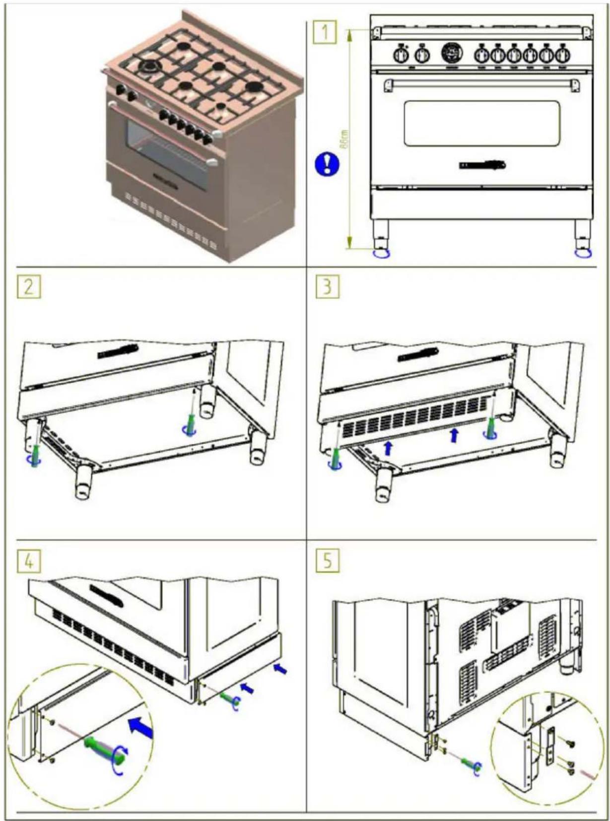
Figure 2
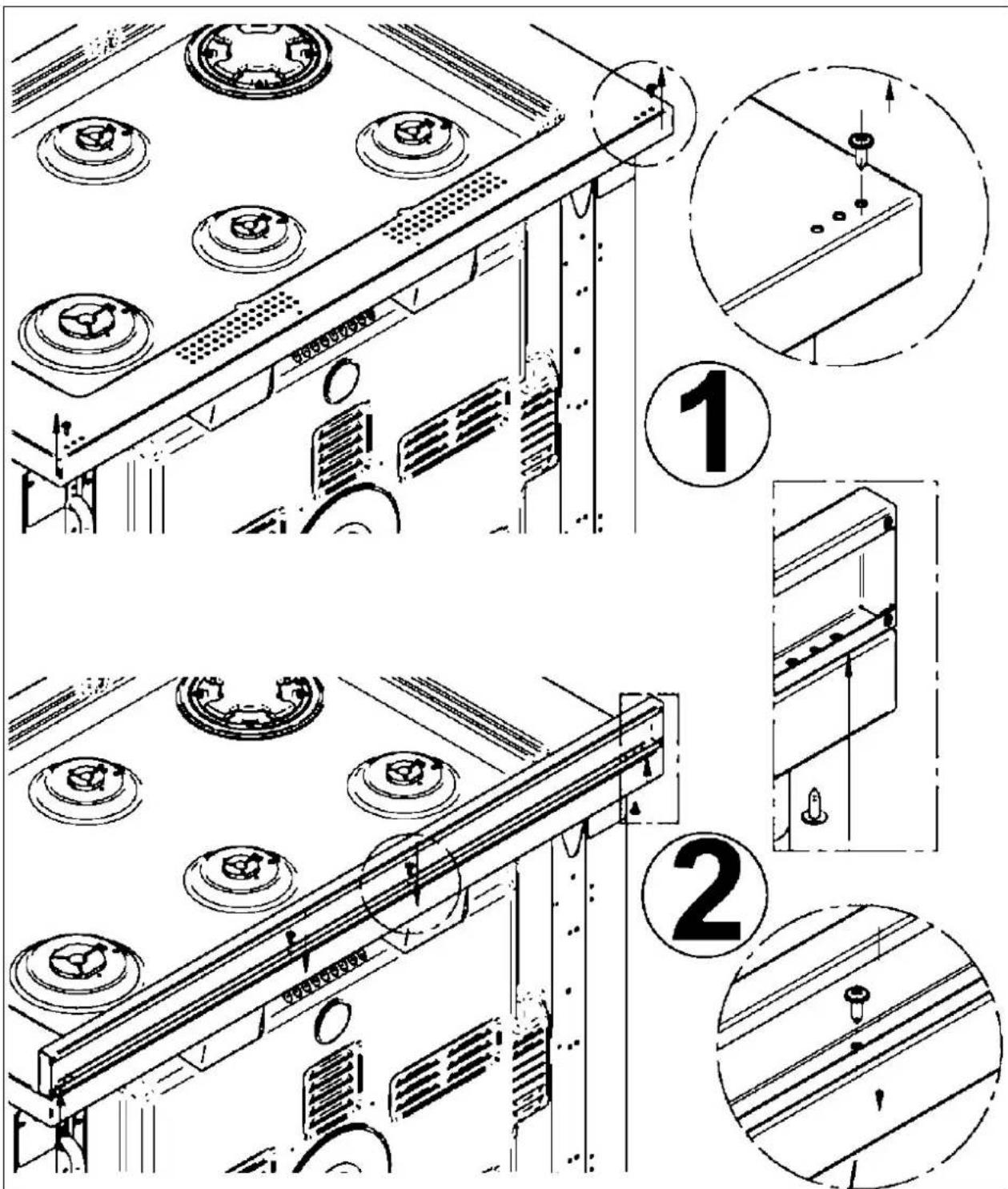
Figure 3

Figure 4A

Figure 4B

Figure 4C

Figure 5

Figure 5A

Figure 6
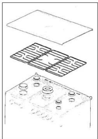
Figure 7

Figure 8
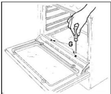
Figure 9 Figure 10

Figure 11


Figure 12

Figure 13

Figure 14
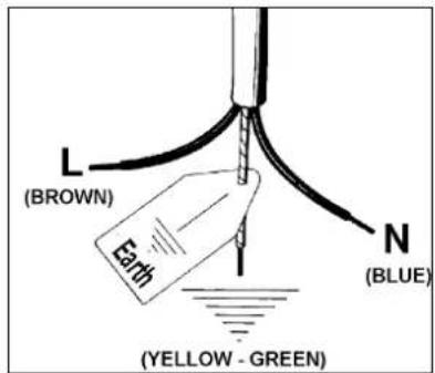
Figure 15

Figure 16

Figure 17
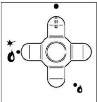
Figure 17

Figure 18
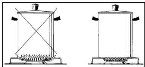
Figure 19


Figure 21

Figure 21

Figure 21A
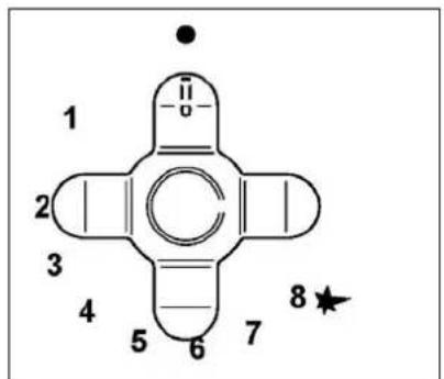
Figure 21A

Figure 22

Figure 23

Figure 24

Figure 24

Figure 25

Figure 25

Figure 26

Figure 26
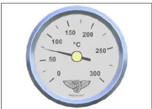
Figure 27

Figure

Figure
29


- INSTALLATION, MAINTENANCE AND USE INSTRUCTIONS FOR FREE-STANDING COOKERS
- HEIGHT-ADJUSTABLE FEET (FIGURE) 1)
- INSTALLING THE TOEKICK PANEL (ONLY AVAILABLE FOR SOME MODELS)
- INSTALLING THE (UPSTAND) RISER
- INSTALLING THE HOB RAIL AND OVEN HANDLE
- INSTALLING THE SYSTEM TO PREVENT OVERTURNING
- CONNECTING THE APPLIANCE TO THE GAS MAINS
- ADJUSTMENT FOR DIFFERENT TYPES OF GAS
- BEFORE CARRYING OUT ANY MAINTENANCE, UNPLUG THE APPLIANCE FROM THE GAS AND ELECTRICITY MAINS
- REPLACING NOZZLES FOR OPERATION WITH ANOTHER TYPE OF GAS
- ADJUSTING THE "MINIMUM" OF THE BURNERS
- CONNECTING THE APPLIANCE TO THE ELECTRIC POWER SUPPLY
- CARING FOR YOUR APPLIANCE
- NOTE: IMPORTANT INFORMATION
- REPLACING COMPONENTS
- USE AND MAINTENANCE MANUAL
- DESCRIPTION OF HOB PARTS
- CONTROL PANEL
- USING THE BURNERS
- RECOMMENDATIONS FOR AN OPTIMAL USE OF THE BURNERS
- NOTE: USE FLAT-BOTTOMED PANS
- USING THE GAS OVEN
- USING THE GAS OVEN FOR MODEL WITH DOUBLE CONTROLS
- GAS OVEN
- FAN GAS OVEN
- USING THE GAS GRILL (SINGLE CONTROL)
- USING THE 2+0 CHANGE-OVER SWITCH (FIGURE 24)
- USING THE ELECTRIC THERMOSTAT FOR MULTI-FUNCTION COOKERS
- USING THE 9-SETTING MULTI-FUNCTION OVEN SELECTOR
- USING THE ELECTRIC OVEN WITH NATURAL CONVECTION
- USING THE ELECTRIC OVEN WITH FAN
- USING THE STATIC ELECTRIC GRILL
- USING THE ELECTRIC GRILL WITH FAN
- USING THE THERMOMETER FIGURE 27
- ELECTRIC OVEN
- USING THE SELF-CLEANING OVEN
- CLEANING THE APPLIANCE
- CLEANING THE HOB
- CLEANING ENAMELLED PARTS
- CLEANING STAINLESS STEEL PARTS
- CLEANING THE FLAME SPREADERS
- CLEANING THE OVEN GLASS PANEL
- CLEANING INSIDE THE OVEN
- CAST IRON OR ALUMINIUM STRIP RACKS
Brand : LA GERMANIA
Model : RI6 4C 61 B X
Category : Cooker