SF40 - Deep fryer Saturn - Free user manual and instructions
Find the device manual for free SF40 Saturn in PDF.


| Product Type | Gas Deep Fryer |
| Model | SF40 |
| Dimensions (W x D x H) | 394 mm x 769 mm x 1196 mm (15.5" x 30.3" x 47.1") |
| Gas Types | Natural Gas or Propane (LPG) |
| BTU Rating | 90,000 BTU/hr |
| Shortening Capacity | 35-40 lbs (16-18 kg) |
| Number of Heat Tubes | 3 |
| Orifice Size (NG / Propane) | 2.5 mm (NG) / 1.6 mm (Propane) |
| Gas Inlet Pressure (NG / Propane) | 4" WC (1.016 kPa) / 10" WC (2.54 kPa) |
| Included Accessories | Crumb rack, basket hanger, adjustable legs (4), drain pipe extension, twin fry baskets (2), manual & warranty |
| Control Type | Thermostat with pilot ignition |
| Temperature Range | Adjustable thermostat (typical frying temps 250°F-350°F) |
| Safety Features | Over-temperature shutoff, high-limit device, gas shutoff valve, cable restraint for casters |
| Construction | Stainless steel exterior |
| Warranty | Refer to manual for details |
| Weight | Approximately 100-120 lbs (45-54 kg) estimated |
| Daily Maintenance | Filter shortening at least daily; clean exterior with mild soap and water; weekly boil-out procedure |
| Spare Parts Availability | Contact authorized service center with model and serial number |
Frequently Asked Questions - SF40 Saturn
User questions about SF40 Saturn
0 question about this device. Answer the ones you know or ask your own.
Ask a new question about this device
Download the instructions for your Deep fryer in PDF format for free! Find your manual SF40 - Saturn and take your electronic device back in hand. On this page are published all the documents necessary for the use of your device. SF40 by Saturn.
USER MANUAL SF40 Saturn
SF SERIES GAS FRYERS
USER'S MANUAL
MODELS:
SF40
SF40
SF70

Intertek
Conforms to ANSI STD Z83.11b -2009
Certified to CSA STD 1.8b -2009

Intertek

natural_image
Technical line drawing of a multi-level kitchen appliance with a basket and door (no text or symbols)(PLEASE RETAIN THIS MANUAL FOR FUTURE REFERENCE)
Post in a prominent location. Instructions to be followed in the event the user smells gas.
Saturn Equipment Primoris Inc., □□□□ Greenwood Plaza%0YG, Suite □□□ Greenwood Village, CO, 80111-2409
Phone: (303) 801-0680
| Model | Dimensions (mm) |
| SF40 | 394×769×1196 |
| SF50 | 394×769×1196 |
| SF70 | 533×769×1196 |
TABLE OF CONTENTS
IMPORTANT FOR YOUR SAFETY 3
INTRODUCTION 4
ORDERING PARTS 4
FRYER CAPACITIES 4
UNPACKING 4
INSTALLATION 5
CLEARANCE 5
LOCATION 5
CODES AND STANDARDS 6
ASSEMBLY 6
FLUE CONNECTION 7
GAS CONNECTION 8
GAS PRESSURE 9
TEST GAS SUPPLY 9
FRYERS WITH CASTERS 9
LEVELING THE FRYER 10
OPERATION 11
OVER-TEMPERATURE SHUTDOWN 11
BEFORE FIRST USE 11
FILLING TANK WITH SHORTENING 12
LIGHTING THE PILOT 13
TURNING ON THE FRYER 14
TROUBLESHOOTING CHART 19
EXPLODED VIEW 20
PART LIST 20
IMPORTANT FOR YOUR SAFETY
THIS MANUAL HAS BEEN PREPARED FOR PERSONNEL QUALIFIED TO INSTALL GAS EQUIPMENT, WHO SHOULD PREFORM THE INITIAL FIELD START-UP AND ADJUSTMENTS OF THE EQUIPMENT COVERED BY THIS MANUAL.
POST IN A PROMINENT LOCATION. THE INSTRUCTIONS TO BE FOLLOWED IN THE EVENT THE SMELL OF GAS IS DETECTED. THIS INFORMATION CAN BE OBTAINED FROM THE LOCAL GAS SUPPLIER.
IMPORTANT
IN THE EVENT A GAS O' 285 IS DETECTED, SHUT DOWN UNITS AT THE MAIN SHUTOFF VALVE AND CONTACT THE LOCAL GAS COMPANY OR GAS SUPPLIER FOR SERVICE.
FOR YOUR SAFETY
DO NOT STORE OR USE GASOLINE OR OTHER FLAMMABLE VAPORS OR LIQUIDS IN THE VICINITY OF THIS OR ANY OTHER APPLIANCE.
Improper installation, adjustment, alteration, service or maintenance may cause property damage, injury or death.
Read the installation, operating and maintenance instructions thoroughly before installing or servicing this equipment.
INTRODUCTION
GENERAL
Saturn Fryers are produced with quality workmanship and materials.
Proper installation, usage and maintenance will result in years of satisfactory performance.
Before installing the fryer, thoroughly read this manual and carefully follow all instruction.
This manual is applicable to model listed on the cover page.
Procedures in this manual will apply to all models unless specified. Pictures and illustrations can be of any model unless the picture or illustration needs to be model specific.
ORDERING PARTS
Customers may order parts directly from their local authorized service center.
If not known, call Saturn Equipment, Primoris Inc. Customer Service at 1-□□□□□□□□□□□□□□□□□□□□□□□□□□□□□□□□□□□□□□□□□□□□□□□□□□□□□□□□□□□□□□□□□□□□□□□□□□□□□□□□□□□□□□□□□□□□□□□□□□□□
620 Greenwood Plaza Blvd. Suite 501. Greenwood Village, Colorado 80111-2409 USA.
To speed up your order, provide the model number, serial number, gas type, item part number and quantity required.
FRYER CAPACITY
| Model | #of Heat Tubes | Orifice (mm) | BTU/hr. Width (cm) Shortening lbs. (kg) | |
| SF40 | NG 3 39 | (2.5) 90,000 | 15.5 (39) 35-40 | (16-18) |
| Propane | 3 43 (1.6) 90,000 15.5 (39) 35-40 | (16-18) | ||
| SF50 | NG 4 39 | (2.5) 120,000 15.5 (39) 45-50 | (21-23) | |
| Propane | 4 43 (1.6) 120,000 15.5 (39) 45-50 | (21-23) | ||
| SF70 | NG 5 39 | (2.5) 150,000 21.0 (53) 65-70 | (29-32) | |
| Propane | 5 43 (1.6) 150,000 21.0 (53) 65-70 | (29-32) | ||
UNPACKING
This fryer was carefully inspected before leaving the factory. Upon acceptance of the shipment, the transportation company assumes full responsibility for safe delivery.
Immediately after unpacking the fryer, check for possible shipping damage. If the fryer is damaged, save the packaging material and contact the carrier within 15 days of delivery.
Check that the following have been included:
Crumb Rack
Basket Hanger
Adjustable Legs (4)
Drain Pipe Extension
Twin Fry Baskets (2)
Manual and Warranty
INSTALLATION
Before installing the fryer, verify that the type of gas (natural or propane) agrees with the specifications on the fryer data plate, which is located on the inside of the door panel. Make sure the fryer is configured for the proper elevation.
Record your fryer model, device, and serial numbers for future reference in the space provided below. This information can be found on the fryer data plate.
Fryer Model No: ____
Device:
Serial No: ____
Clearances
Minimum clearance from combustible construction:
6" (15 cm) from the sides of the fryer
6" (15 cm) from the back of the fryer
The fryer may be installed on combustible floors
Minimum clearance from noncombustible construction:
6" from the sides of the fryer
6" from the back of the fryer
Between the fryer and any open-top flame units:
16" (41 cm)
Allow space for servicing and operation.
Location
Install fryer in an area with sufficient air supply for gas combustion at fryer burners.
Do not obstruct the flow of combustion and ventilation air.
Provide adequate clearance for air openings into the combustion chamber.
Do not permit fans to blow directly onto fryer.
Avoid wall-type fans, which create cross-currents within a room.
Avoid open windows next to sides or back.
CODES AND STANDARDS
The fryer must be installed in accordance with:
In the United States:
State and local codes, or in the absence of local codes, with:
National Fuel Gas Code, ANSI-Z223.1/NFPA #54 (latest edition).
Copies may be obtained from The American Gas Association Accredited Standards
Committee Z223, @ 400 N. Capital St. NW, Washington, DC 20001
& Secretary Standards Council, NFPA,
1 Batterymarch Park Quincy, MA 02169-7471.
NFPA Standard #96 Vapor Removal from Cooking Equipment, latest edition, available from the National Fire Protection Association, Batterymarch Park, Quincy, MA.
In the commonwealth of Massachusetts all gas appliances vented through a ventilation hood or exhaust system with a damper or with a power means of exhaust shall comply with 248 CMR.
In Canada:
Local codes
CAN/CSA-B149.1 Natural Gas Installation (latest edition).
CAN/CSA-B149.2 Propane Installation Code (latest edition), available from the Canadian Gas Association
178 Rexdale Blvd, Etobicoke, Ontario Canada M9W 1R3.
ASSEMBLY
The fryer must be restrained to prevent tipping and the splashing of hot liquid. The means of restraint may be the manner of installation, such as connection to a battery of appliances, installing the fryer in an alcove, or by separate means such as adequate ties.
Note: The gas supply pressure at gas inlet should be less than 3.5 kPa.
FLUE CONNECTION
Make the flue connection as follows:
Comply with Vapor Removal from Cooking Equipment, ANSI-NFPA Standard #96 (latest edition), available from the National Fire Protection Association Batterymarch Park, Quincy, MA 02269
Locate the fryer under a hood with adequate connection to an exhaust duct. The hood must extend 6" (15 cm) beyond fryer on both sides.
Clearance above the fryer should be adequate for combustion byproducts to be removed efficiently.
An 18" (46 cm) minimum clearance should be maintained between the flue vent and the filters of the hood venting system.
Never make flue connections directly to the fryer.
Do not obstruct the flow of the gases from the appliance. Proper air balance should be maintained in the room.
GAS CONNECTION
All gas supply connections and any pipe joint compound must be resistant to the action of propane gases
The gas inlet is located on the lower rear of the fryer. Codes require that a gas shutoff valve be installed in the gas line ahead of the fryer.
The gas supply line must be at least the equivalent of 12 " X (12.7 mm) iron pipe for single units and 1-1/4" (31.75 mm) for batteries. If using the optional quick-disconnect flex hose, 34 " X (19 mm) iron pipe for single units and 1-1/4" (31.75 cm) iron pipe for batteries.
Make sure the pipes are clean and free of obstructions, dirt, and piping compound. A battery requires one or two connections of appropriate size for the gas requirement.
Prior to lighting, check all joints in the gas supply line for leaks. Use soap and water solution. Do not use an open flame.
After piping has been checked for leaks, fully purge gas pipes to remove air.
GAS PRESSURES (ALL MODELS):
The gas pressure should be set at 4" W.C. (Water Column) (1.016 kPa) of pressure for natural gas and 10" W.C. (2.54kPa) of pressure for propane gas. If incoming pressure exceeds 12 PSI (3.5 kPa), an additional pressure regulator must be installed.
TESTING THE GAS SUPPLY PIPING SYSTEM:
When test pressures exceed 12 PSI (3.5 kPa), the fryer and its individual shutoff valve must be disconnected from the gas supply piping system.
When test pressures are 12 PSI (3.5 kPa) or less, the fryer must be isolated from the gas supply piping system by closing its individual shutoff valve.
Fryers with Casters:
Separate instructions for installing casters are included in with the casters:
The installation shall be made with a connector that complies with the Standard for Connectors for Movable Gas Appliances, ANSI Z21.69 or Connectors for Moveable Gas Appliances, CAN/CGA-6.16, and a quick-disconnect device that complies with the Standard for Quick-Disconnect Devices for Use with Gas Fuel, ANSI z21.41 or Quick-Disconnect Devices for Use with Gas Fuel, CANI-6.9.
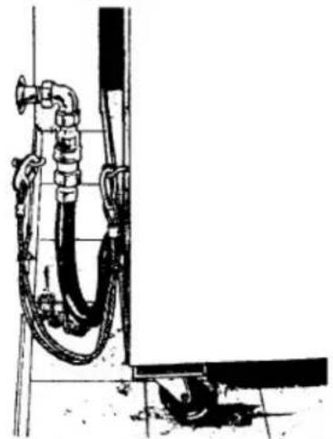
When installing a quick disconnect, you must also install a means for limiting the movement of the fryer. This device will prevent the gas line or quick disconnect from being pulled apart.
The restraining device can be attached to the cutout on the back panel.
See illustration for location
In Australia, use only the caster supplied by the manufacturer for the fryer device.
The fryer must be installed using a hose assembly restraining device
to limit the movement of the appliance in accordance with AS1869.
The fryer must be installed with a connector complying with the above codes.
The fryer gas line must be installed with restraining cable to guard against of strain to the connector.
See illustration(Below Picture)
The fryer must be installed with the casters provided.
If the gas cable restraint is ever to be disconnected, first turn the gas supply off
CABLE RESTRAINT
Please refer to the illustration below when installing cable restraint on all moveable gas fryers.
natural_image
Technical line drawing of a pipe system with hoses and fittings, no visible text or symbolsI-bolt is to be secured to the building using acceptable building construction practices.
CAUTION
DRY WALL CONSTRUCTION
Secure I-bolt to a building stud. Do not attach to dry wall only. Also, locate the I-bolt at the same height as the gas service. Preferred installation is approximately six inches to either side of service. Cable restraint must be at least six inches shorter than flexible gas line.
LEVELING THE FRYER
Check the level of the fryer by placing a level on top of the fryer after gas connections have been made.
Ensure that the fryer is level front-to-back and side-to-side in the final installed position.
If using casters, lock the casters after unit is level.
OPERATION
WARNING
Hot oil and parts can cause burns. Use care when operating, cleaning and servicing the fryer.
WARNING
Spilling hot frying compound can cause severe burns. Do not move fryer without draining all frying compound from the tank.
If the shortening becomes overheated, a high-temperature shutoff device will turn the gas valve off and extinguish the pilot.
If the fryer shuts down due to overheating, DO NOT relights the pilot until the shortening temperature is below 300 F (149 C).
If an overheating situation persists, contact your local Saturn authorized service office.
BEFORE FIRST USE
Cleaning
New units are wiped down at the factory to remove any visible signs of dirt, oil, grease, etc. remaining from the manufacturing process.
Before any food preparation, thoroughly wipe protective oil from all surface parts and the tank interior with hot soapy water to remove any film residue and dust or debris.
NOTICE
Do not use chlorine or sulfate/sulfide cleaners.
Wash any accessories shipped with unit.
Rinse fryer and accessories thoroughly and drain the fryer.
Wipe tank completely dry with a soft, clean cloth.
FILLING TANK WITH SHORTENING
NOTICE
Solid shortening should NOT be used with fryers.
Melting solid shortening will damage the tank and void your warranty.

A Fryer Tank
B MIN and MAX Fill Level Lines
C Heat Pipes
D Cold Zone
E Drain Pipe
Close the drain valve.
Fill the fryer tank with liquid shortening.
Shortening level should be between the min and max lines in the fryer tank.
Shortening will expand when heated. Do not fill the fryer tank past the MAX line.
Add fresh shortening as needed to maintain oil level.
LIGHTING THE PILOT

A Gas Valve Knob
B Gas Supply
C ThermostatKnob
- Open the door.
- Tur n the thermostat OFF (see figure below, view A). The thermostat is located behind the door.
- Push the gas control valve knob and turn to OFF. Wait 5 minutes for unburned gas to vent away.
- Push and turn gas control valve knob to the "L" in PILOT (see figure below, view B).
- While still holding the knob in, light the pilot with a lit flame. Continue to depress the knob until pilot remains lit when knob is released. If the pilot does not remain lit, repeat step 3 through 5.
- Depress and turn gas control knob to ON (See figure below, view C).
- If gas supply is interrupted, repeat steps 2 through 6.
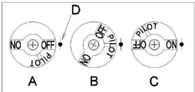
A Gas Valve Knob, View A
B Gas Valve Knob, View B
C Gas Valve Knob, View C
D Indicator Point, All Views
TURNING ON THE FRYER
☐ Set the temperature knob to desired temperature.
☐ After the set temperature has been reached, the thermostat shuts off the gas flow to burners.
☐ The pilot remains lit. The burners will cycle on and off, maintaining the set temperature.
- Turn the thermostat OFF.
- To keep the pilot lit, turn the gas valve to "L" in Pilot.
- To shut off all gas to the system, including the pilot, turn the gas valve knob to OFF.
EXTENDED SHUTDOWN
- Turn the thermostat knob to OFF.
- Push in the pilot knob and turn to OFF.
- Thoroughly drain the fryer. Refer to DRAINING THE FRYER.
- Clean the fryer according to CLEANING.
- Turn off the main gas shutoff valve.
BASIC FRYING INSTRUCTION
☐ Set the desired temperature and allow shortening to heat up to that temperature.
Fry items that are about the same size together to ensure equal cooking
Drain or wipe dry raw or wet foods to minimize splatter when lowering into hot shortening.
☐ Add fresh shortening as needed.
Fry Basket Guidelines
☐ Do not overfill baskets. (See table for recommended basket capacities below) Carefully lower basket into oil.
☐ When frying doughnuts and fritters, turn food only once during frying.
When cooking French fries or onion rings, shake the basket several times in a way that does not splatter the shortening.
☐ Batter-covered foods should be dropped carefully, one by one, into shortening or basket. If you use the basket, first dip the basket into the shortening to reduce batter-build up on basket surfaces.
When frying is completed, remove basket or product.
Hang basket on rear hanger.
Fry Basket Capacity:
SF40, SF50: Recommended pounds per basket are 1.5 lbs. (0.7 kg).
EXTENDING SHORTENING LIFE
Shortening life can be extended by the following guidelines:
Do not salt foods over the fryer.
Use good-quality shortening.
Filter shortening daily (at a minimum).
Replace shortening if it becomes poorly flavored.
Keep equipment and surrounding clean.
Set thermostat correctly.
Remove excess moisture and particles from food products before placing on fryer.
DRAINING THE TANK
- Turn the thermostat to OFF.
- To keep the pilot lit, turn the gas valve to PILOT.
- Direct the drain spout into the container that you want to drain the shortening into.
- Open the drain valve. The oil will drain into the container.
When the container is full or the fryer tank is empty, close the drain valve.
Repeat this step until the fryer is empty.
-
If desired, perform the weekly clean-out as described under CLEANING.
-
Once tank is completely empty, add new shortening and set thermostat to desired temperature.
WARNING
DAILY FILTERING
Hot oil and hot parts can cause burns. Use care when operating, cleaning, and servicing the fryer.
☐ Filter shortening at least once a day. Refer to the instructions provided with your filtering equipment.
☐ A cold fryer will not drain properly.
Always filter shortening between 250F and 350F.
The shortening in the cold zone area will remain hard if the heat is only on for a few minutes.
If necessary, use the clean-out rod to carefully stir the hard shortening to an area above the cold zone where it will melt.
Use the tank brush to help clear sides and tubes of debris.

A Fryer Tank
B MIN and MAX Fill Level Lines
C Heat Pipes
D Cold Zone
E Drain Pipe
CLEANING
WARNING
Hot oil and hot parts can cause burns. Use care when operating, cleaning, and servicing the fryer.
Daily
Clean your fryer regularly with the tank brush along with a damp cloth, and polish with a soft dry cloth. If regular cleaning is neglected, grease will be burned on and discolorations may form.
Fingerprints are sometimes a problem on highly polished surfaces of stainless steel. They can be minimized by applying a cleaner that will leave a thin oily or waxy film.
Clean all exterior surfaces of your fryer at least once daily.
Use a damp cloth with warm water and a mild soap or detergent.
NOTICE
Do not use chlorine or sulfate/sulfide cleaners.
Rinse thoroughly, and then polish with a soft dry cloth.
Keep the fryer exterior clean and free of accumulated grease to prevent heavy stains from forming. If regular cleaning is neglected, grease will be burned on and discolorations may form.
Remove discolorations by washing with any detergent or soap and water.
Use a self-soaping, non-metallic scouring pad for particularly stubborn discolorations.
Always rub with the grain of the stainless steel.
Do not use a metallic scoring pad or harsh cleaners.
BOIL OUT PROCEDURE
Weekly or as required:
- Drain the tank as described under DRAINING THE TANK.
- Once the shortening has been drained, flush out scraps and sediment with a small amount of warm shortening, using tank brush. Allow the tank to drain thoroughly.
- Close the drain valve and fill tank with non-corrosive, grease-dissolving commercial cleaner. Follow the manufacture's instructions.
Do not use chlorine or sulfate/sulfide cleaners.
-
Add commercial boil-out solution.
Solution level must be between the MIN and MAX levels on the fryer tank. -
Set thermostat to the temperature recommended for the solution being used. Allow solution to simmer for about 15 to 20 minutes.
-
Drain the cleaning solution from the tank.
-
Close the drain valve and refill the tank with water. Add 1 cup (1/4 L) of vinegar to neutralize alkaline left by the cleaner. Solution level must be between the MIN and MAX level on the fryer tank.
-
Bring the solution to a simmer only, turn the thermostat off. Allow to stand for a few minutes.
-
Drain the tank according to DRAINING THE TANK. Rinse thoroughly with clear, hot water. All traces of cleaner must be removed. Dry the tank thoroughly.
-
Close the drain valve and add shortening. Follow the FILLING TANK WITH SHORTENING procedure in this manual. The fryer is now ready for use.
MAINTENANCE
Hot oil and hot parts can cause burns.
Use carefully when operating, cleaning, and servicing the fryer.
Spilling hot fryer compound can cause severe burns.
Do not move fryer without draining all frying compound from the tank.
The fryer should be restrained to prevent tipping when installed in order to avoid the splashing of hot liquid.
The means of restraint may be the manner of installation, such as connection to a battery of appliances or installing the fryer in an alcove, or by separate means, such as adequate ties.
FLUE VENT INSPECTION
When the fryer is cool, inspect annually. Check the flue and clear any obstructions.
Service in the US and Canada
Contact you local Saturn Service office or address on the front of this manual.
Troubleshooting Chart:
Problem:
Probable Cause:
No Heat:
Thermostat dial not turned on.
Pilot not lit.
Gas supply not turned on.
Wire connections loose (call service)
Wires connections need cleaning (call service)
Thermopile (call service technician)
Insufficient or too much heat:
Thermostat dial not set to desired temperature.
High limit tripped (call service technician)
Temperature probe (call service technician)
Tank will not drain:
Shortening too cold.
Drain pipe clogged with debris.
Exploded View

Part List
| NUMBER | DESCRIPTION NUMB | ER DESCRIPTION | |
| 1 Plate | for hanging basket 20 Thermostat knob | ||
| 2 Tank | assembly 21 Holder | ||
| 3 Clamp | for probe 2 22 Temperature | ||
| 4 Clamp | for probe 1 23 Thermostat | ||
| 5 Fire damper plate | 24 | Test plug screw | |
| 6 | Rear board of body | 25 | Gas-distributing pipe |
| 7 | Lower rear cross beam | 26 | Injector pipe |
| 8 | Side board of body | 27 | Injector |
| 9 Nut | 28 Burner | ||
| 10 | Adjustable foot | 29 | Connecting plate for pilot |
| 11 | Inlet pipe | 30 | Fixing plate for pilot |
| 12 | Elbow pipe | 31 | Upper front cross beam |
| 13 | Valve | 32 | Exterior door plate |
| 14 | Inside connector | 33 | Supporting grid |
| 15 | Outside connector | 34 Front decoration board | |
| 16 | Inlet pipe connector | 35 | Mounting of distributing pipe |
| 17 Oil drainage valve | 36 | Fixing plate for probe | |
| 18 | Oil drainage pipe | 37 | Hanging basket |
| 19 | Supporting plate for door shaft | ||
- SF SERIES GAS FRYERS
- USER'S MANUAL
- (PLEASE RETAIN THIS MANUAL FOR FUTURE REFERENCE)
- IMPORTANT FOR YOUR SAFETY
- IMPORTANT
- FOR YOUR SAFETY
- INTRODUCTION
- GENERAL
- ORDERING PARTS
- FRYER CAPACITY
- UNPACKING
- INSTALLATION
- Clearances
- Location
- CODES AND STANDARDS
- In the United States:
- In Canada:
- ASSEMBLY
- Note: The gas supply pressure at gas inlet should be less than 3.5 kPa.
- FLUE CONNECTION
- GAS CONNECTION
- GAS PRESSURES (ALL MODELS):
- TESTING THE GAS SUPPLY PIPING SYSTEM:
- Fryers with Casters:
- CABLE RESTRAINT
- CAUTION
- LEVELING THE FRYER
- OPERATION
- BEFORE FIRST USE
- Cleaning
- NOTICE
- FILLING TANK WITH SHORTENING
- LIGHTING THE PILOT
- TURNING ON THE FRYER
- EXTENDED SHUTDOWN
- BASIC FRYING INSTRUCTION
- Fry Basket Guidelines
- Fry Basket Capacity:
- EXTENDING SHORTENING LIFE
- DRAINING THE TANK
- WARNING
- DAILY FILTERING
- Hot oil and hot parts can cause burns. Use care when operating, cleaning, and servicing the fryer.
- Daily
- BOIL OUT PROCEDURE
- Weekly or as required:
- MAINTENANCE
- FLUE VENT INSPECTION
- Troubleshooting Chart:
- Exploded View
Brand : Saturn
Model : SF40
Category : Deep fryer