
LPAUS - Media card Chief - Free user manual and instructions
Find the device manual for free LPAUS Chief in PDF.


| Product Type | Multimedia Card |
| Brand | Chief |
| Model | LPAUS |
| Interface | PCI Express x1 |
| Dimensions (L x W x H) | 120 x 80 x 20 mm |
| Weight | 50 g |
| Power Consumption | 5 W |
| Input Voltage | 3.3V / 12V (from PCIe slot) |
| Operating Temperature | 0°C to 40°C |
| Storage Temperature | -20°C to 60°C |
| Supported OS | Windows 10/11, Linux |
| Video Input | HDMI |
| Audio Input | 3.5 mm stereo jack |
| Maximum Resolution | 1920 x 1080 (1080p) |
| Functions | Video capture, audio recording, live streaming |
| Package Contents | LPAUS card, low-profile bracket, driver CD, user manual |
| Maintenance | Clean with a soft dry cloth; avoid liquids |
| Safety Precautions | Install in a well-ventilated slot; use anti-static wrist strap |
| Spare Parts & Repairability | No user-serviceable parts; contact support for repairs |
Frequently Asked Questions - LPAUS Chief
User questions about LPAUS Chief
0 question about this device. Answer the ones you know or ask your own.
Ask a new question about this device
Download the instructions for your Media card in PDF format for free! Find your manual LPAUS - Chief and take your electronic device back in hand. On this page are published all the documents necessary for the use of your device. LPAUS by Chief.
USER MANUAL LPAUS Chief
INSTALLATION INSTRUCTIONS

natural_image
Technical line drawing of a mechanical support structure with three legs and a vertical column (no text or symbols)Height Adjustable Video Cart
DISCLAIMER
Milestone AV Technologies and its affiliated corporations and subsidiaries (collectively "Milestone"), intend to make this manual accurate and complete. However, Milestone makes no claim that the information contained herein covers all details, conditions or variations, nor does it provide for every possible contingency in connection with the installation or use of this product. The information contained in this document is subject to change without notice or obligation of any kind. Milestone makes no representation of warranty, expressed or implied, regarding the information contained herein. Milestone assumes no responsibility for accuracy, completeness or sufficiency of the information contained in this document.
Chief® is a registered trademark of Milestone AV Technologies. All rights reserved.
Chief® is a registered trademark of Milestone AV Technologies. All rights reserved.
DEFINITIONS
MOUNTING SYSTEM: A MOUNTING SYSTEM is the primary Chief product to which an accessory and/or component is attached.
ACCESSORY: AN ACCESSORY is the secondary Chief product which is attached to a primary Chief product, and may have a component attached or setting on it.
COMPONENT: A COMPONENT is an audiovisual item designed to be attached or resting on an accessory or mounting system such as a video camera, CPU, screen, display, projector, etc.

WARNING: A WARNING alerts you to the possibility of serious injury or death if you do not follow the instructions.

CAUTION: A CAUTION alerts you to the possibility of damage or destruction of equipment if you do not follow the corresponding instructions.

IMPORTANT SAFETY INSTRUCTIONS

WARNING: Failure to read, thoroughly understand, and follow all instructions can result in serious personal injury, damage to equipment, or voiding of factory warranty! It is the installer's responsibility to make sure all mounting systems are properly assembled and installed using the instructions provided.

WARNING: Failure to provide adequate structural strength for this mounting system can result in serious personal injury or damage to equipment! It is the installer's responsibility to make sure the structure to which this component is attached can support five times the combined weight of all equipment. Reinforce the structure as required before installing the mounting system.

WARNING: Exceeding the weight capacity can result in serious personal injury or damage to equipment! It is the installer's responsibility to make sure the combined weight of all components attached to the LPAU up to (and including) the display does not exceed 200 lbs (90.7 kg). Use with heavier televisions may result in instability causing tip over resulting in death or serious injury!

WARNING: Use this mounting system only for its intended use as described in these instructions. Do not use attachments not recommended by the manufacturer.

WARNING: Never operate this mounting system if it is damaged. Return the mounting system to a service center for examination and repair.

WARNING: Do not use this product outdoors.

WARNING: RISK OF INJURY TO PERSONS! Do not place video equipment such as televisions or computer monitors on cart legs.

WARNING: RISK OF SERIOUS INJURY OR DEATH!
Placing a remote control or toy on the cart may encourage a child to climb onto the cart causing the cart to tip over onto the child. DO NOT place remote controls or toys on the cart!

WARNING: RISK OF SERIOUS INJURY OR DEATH! Relocating audio and/or video equipment to the cart may result in the cart collapsing or overturning onto a child. DO NOT relocate audio and/or video equipment to the cart!
NOTE: The LPAU cart has no user serviceable parts.
NOTE: The LPAU cart can support screen sizes up to a maximum of 90" wide.
--SAVE THESE INSTRUCTIONS--
DIMENSIONS
![CABLE CORD WRAP HOOKS +/-2° ROLL ADJUSTMENT +/-5° TILT ADJUSTMENT 34.86 [885.5] 15.75 [400.0] 7.87 [200] MIN 31.50 [800] MAX CABLE MANAGEMENT COVERS 70.09 [1780.3] MAX HEIGHT TO CENTER OF DISPLAY 50.09 [1272.3] MIN HEIGHT TO CENTER OF DISPLAY CABLE MANAGEMENT COVERS 47.74 [1212.5] 7.46 [189.4] 36.99 [939.5]](/content/2026/05/1030729/images/664ab059059e8cc5cb8f2c4f0ea91b35c4c9ef31b253f5f10a9a22214d6a32db.jpg)
LEGEND
 | Tighten Fastener |  | Pencil Mark |
| Apretar elemento de fijación | Marcar con lápiz | ||
| Befestigungsteil festziehen | Stiftmarkierung | ||
| Apertar fixador | Marcar com lápis | ||
| Serrare il fissaggio | Segno a matita | ||
| Bevestiging vastdraaien | Potloodmerkteken | ||
| Serrez les fixations | Marquage au crayon | ||
 | Loosen Fastener |  | Drill Hole |
| Aflojar elemento de fijación | Perforar | ||
| Befestigungsteil lösen | Bohrloch | ||
| Desapertar fixador | Fazer furo | ||
| Allentare il fissaggio | Praticare un foro | ||
| Bevestiging losdraaien | Gat boren | ||
| Desserrez les fixations | Percez un trou | ||
 | Phillips Screwdriver |  | Adjust |
| Destornillador Phillips | Ajustar | ||
| Kreuzschlitzschraubendreher | Einstellen | ||
| Chave de fendas Phillips | Ajustar | ||
| Cacciavite a stella | Regolare | ||
| Kruiskopschroevendraaier | Afstellen | ||
| Tournevis à pointe cruciforme | Ajuster | ||
 | Open-Ended Wrench |  | Remove |
| Llave de boca | Quitar | ||
| Gabelschlüssel | Entfernen | ||
| Chave de bocas | Remover | ||
| Chiave a punte aperte | Rimuovere | ||
| Steeksleutel | Verwijderen | ||
| Clé à fourche | Retirez | ||
 | By Hand |  | Optional |
| A mano | Opcional | ||
| Von Hand | Optional | ||
| Com a mão | Opcional | ||
| A mano | Opzionale | ||
| Met de hand | Optie | ||
| À la main | En option | ||
 | Hex-Head Wrench |  | Security Wrench |
| Llave de cabeza hexagonal | Llave de seguridad | ||
| Sechskantschlüssel | Sicherheitsschlüssel | ||
| Chave de cabeça sextavada | Chave de segurança | ||
| Chiave esagonale | Chiave di sicurezza | ||
| Zeskantsleutel | Veiligheidssleutel | ||
| Clé à tête hexagonale | Clé de sécurité |
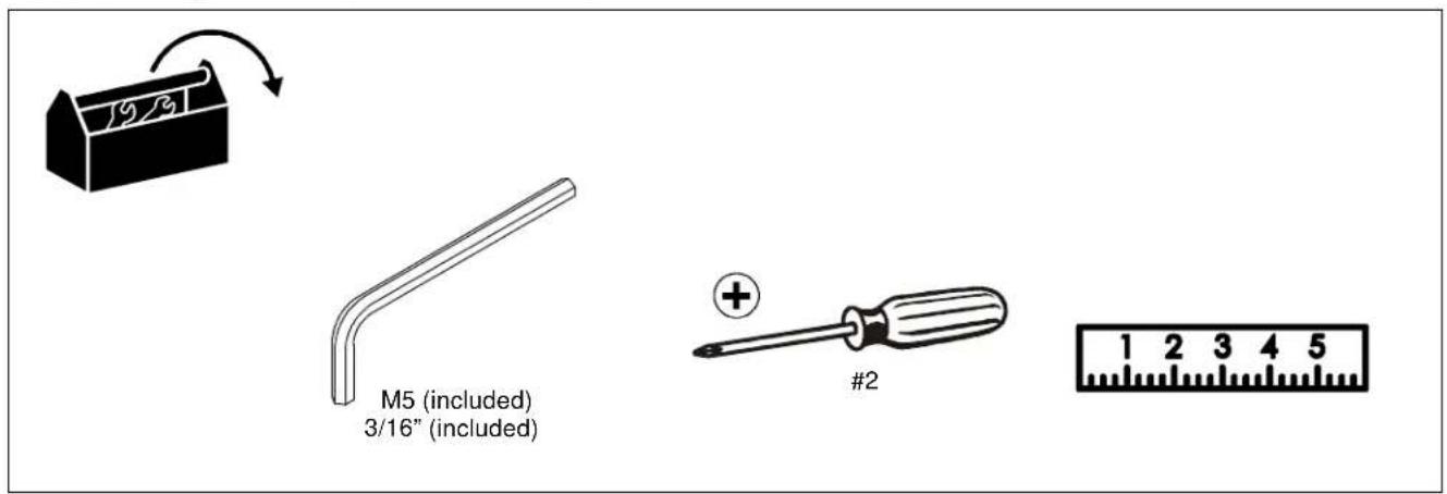
TOOLS REQUIRED FOR INSTALLATION
PARTS
![A (4) (upright cover) B (2) (interface upright] C (1) (column upper cover) D (1) (column inner cover) E (1) (interface head assembly) F (1) (column assembly) G (1) [back cover] T (1) [Hardware bag] TA (4) M4x12mm TB (4) M4x20mm TC (4) M4x25mm TD (4) M5x12mm TE (4) M5x20mm TF (4) M5x25mm TG (4) M6x12mm TH (4) M6x20mm TI (4) M6x25mm TJ (4) M8x12mm TK (4) M8x20mm TL (4) M8x30mm TM (8) [Nesting spacer] TN (4) [Universal washer] N (5) 5/16-18 x 3/4" P (4) 5/16-18 x 3 3/4" Q (2) 1/4-20 x 1/2" R (1) 3/16" U (10) [FCA clip] V (10) [cable tie] W (1) 3/16"](/content/2026/05/1030729/images/0cc679ae90bf4466fdb00140dd3b52554a58f3e2373c808ed56ecbc7df7ee450.jpg)
Assembly And Installation

CAUTION: Attachment holes may be damaged if a power drill is used to insert button head cap screws. Screws should first be inserted and turned BY HAND with the hex key or with a hand-held screwdriver BEFORE using the hex head drill bit and power drill to complete the attachment.
Cart Assembly
- Carefully set column assembly (F) on its left side. (See Figure 1)
- Place right transition cover (M) on right cart leg (J), lining up the holes on the cover with the holes on the leg and column assembly base. (See Figure 1)
- Use two 5/16-18 x 3 3/4" button head cap screws (P) to secure leg (J) and cover (M) to column assembly (F). (See Figure 1)

Figure 1
- Turn column assembly (F) onto its right side. (See Figure 2)
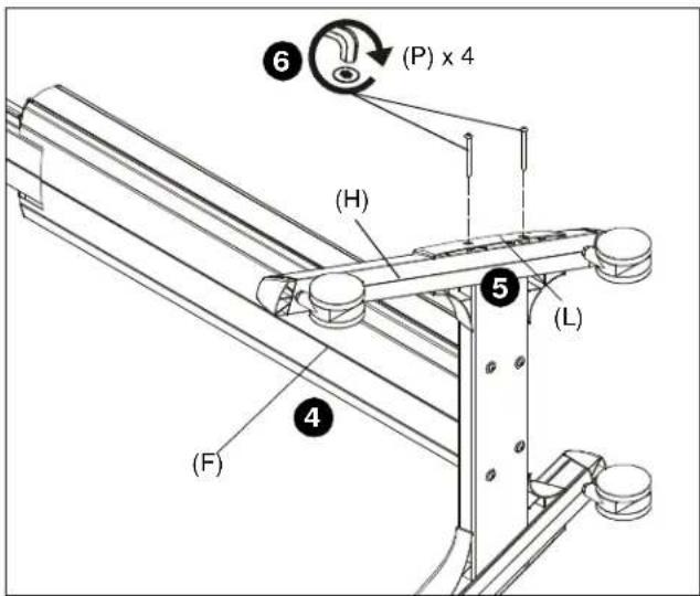
Figure 2
- Place left transition cover (L) on left cart leg (H), lining up the holes on the cover with the holes on the leg and column assembly base. (See Figure 2)
- Use two 5/16-18 x 3 3/4" button head cap screws (P) to secure leg (H) and cover (L) to column assembly (F). (See Figure 2)
- Slide interface head assembly (E) into column assembly (F). (See Figure 3)
- Use four 5/16-18 x 3/4" button head cap screws (N) to secure interface head assembly (E) to column assembly (F). (See Figure 3)

Figure 3
-
Use remaining 5/16-18 x 3/4" button head cap screw (N) to secure column upper cover (C) to interface head assembly (E). (See Figure 4)
-
Snap column inner cover (D) onto column assembly (F). (See Figure 4)

Figure 4
Display Installation

WARNING: Exceeding the weight capacity can result in serious personal injury or damage to equipment! It is the installer's responsibility to make sure the combined weight of all components attached to the LPAU up to (and including) the display does not exceed 200 lbs (90.7 kg). Use with heavier televisions may result in instability causing tip over resulting in death or serious injury!
- Lay display face down on protective surface.

CAUTION: Using screws of improper diameter may damage your display! Proper screws will easily thread into display mounting holes.
- Select screw diameter by examining hardware (TA-TL) (4mm, 5mm, 6mm or 8mm) and comparing with mounting holes on display. (See Figure 6)
- Select spacers: (See Figure 6)
- If mounting holes are not recessed and both uprights (B) can lay flat against display, then no spacers are required.
- If mounting holes are recessed, or if protrusions prevent uprights (B) from laying flat, then spacers (TL or TM) must be used.

CAUTION: Using screws of improper length may damage your display! Proper screws will have adequate thread engagement without contacting bottom of display mounting holes.
- Select screw length: (See Figure 6)
- Using your hand, insert SHORTEST length screw of selected diameter (TA, TD, TG or TJ) through universal washer (TN), uprights (B), nesting spacer (TM), into display mounting hole. Do NOT thread screw into hole at this time.
NOTE: Universal washers (TN) are not needed if using M8 button head cap screws (TJ, TK or TL).
- Proper screw length requires base of screw head to protrude above flat washer a distance equal to or greater than the screw diameter. If screw length is inadequate, select longer screw. Select shortest screw which will protrude the required distance.
- Place uprights (B) on display, ensuring: (See Figure 6)
- Center of uprights (B) are as close to the center of the back of display as possible after being installed. Center of bracket is indicated by the diamond-shaped hole.
- Use selected screws and spacers to install two interface uprights (B) to back of display. (See Figure 6)
IMPORTANT ! : The M8 screws do NOT require a washer. Use the universal washer (TN) only with M4, M5 and M6 screws.
NOTE: The nesting spacers (TM) may be used separately, or put two together in different configurations to create different size spacers. (See Figure 5)
![(Single) (Nested) (Stacked) 0.375 [9.5] 0.563 [14.3] 0.750 [19.1]](/content/2026/05/1030729/images/b2cad3398b9436605b461655209ca8a1c0b199d58aef4a4fc1f7e43247b888fb.jpg)
Figure 5

Figure 6

WARNING: Display may be very heavy! Ensure display may be safely lifted and maneuvered as required to install on cart. Failure to take adequate precautions can result in serious personal injury or damage to equipment!
- Position latches on interface uprights so that they are in the "open" position. (See Figure 7)
- Hang interface uprights (B) on interface head assembly (E). (See Figure 7)
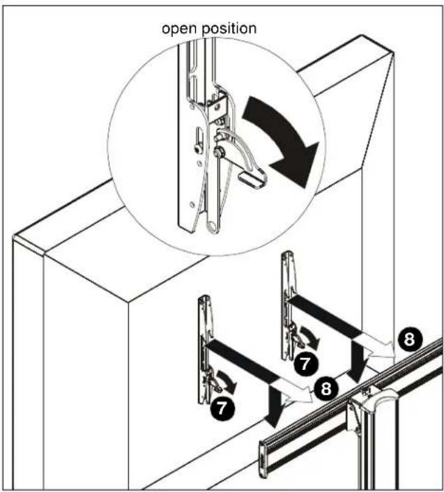
Figure 7
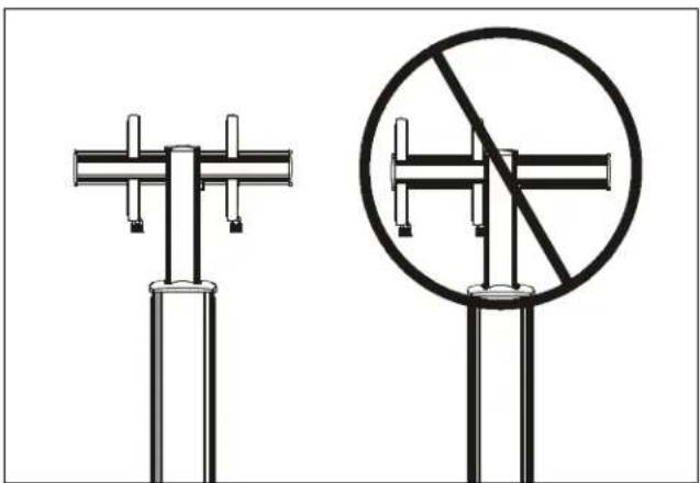
IMPORTANT ! : In order to ensure an even mount, install uprights to be centered over column assembly. Do NOT install both uprights to the same side of column assembly! (See Figure 8)
natural_image
Two types of street traffic light fixtures: a vertical pole with cross-shaped supports and a circular cross-section with diagonal lines (no text or symbols)Figure 8
- Move latches on interface uprights to the "closed" position to secure display to head assembly. (See Figure 9)

Figure 9
- Snap four upright covers (A) onto uprights. (See Figure 10)
NOTE: Tabs on inside of covers (A) will snap directly into holes on uprights to ensure a secure connection.

Figure 10
- (Optional) Use padlocks (not provided) to secure uprights to head assembly. (See Figure 10)
Cable Management
NOTE: The following cable management options may vary based on type of display being mounted and user preference.
- Use two 1/4-20 x 1/2" Phillips pan machine screws (Q) to attach two cable hooks (K) to bottom of column assembly (F). (See Figure 11)

Figure 11
- Place FCA clip (U) into groove on back of Fusion mount with clip handle in a vertical position. (See Figure 12)
- Rotate FCA clip (U) 90° in either direction until clip handle is in a horizontal position. (See Figure 12)
- Repeat Steps 1-2 for all clips to be installed.
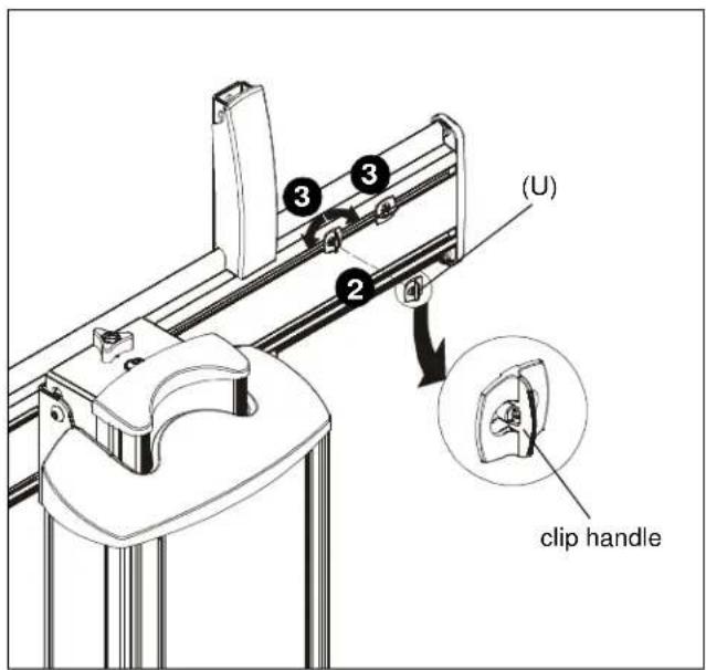
Figure 12
- Route cables along FCA clips to be used for cable management. (See Figure 13)
- Use cable ties (V) to secure cables to FCA clips. (See Figure 13)
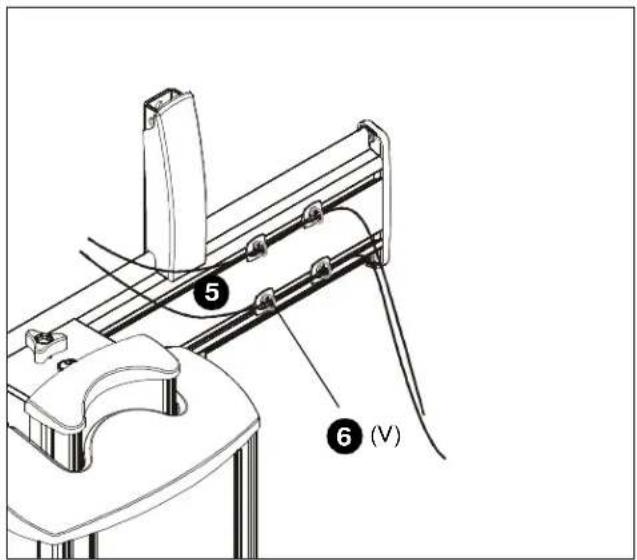
Figure 13
- Route cables from display through front channel of column assembly. (See Figure 14)

Figure 14
- Route cables down column channel, tucking them behind height-adjustment carriage and underneath bracket holding height-adjustment shaft. (See Figure 15)
- Wrap cables around cable hooks as desired. (See Figure 15)
- Snap back cover (G) onto back of column assembly making sure cables fit through opening at bottom of cover. (See Figure 15)

Figure 15
Adjustments
Height Adjustment
- Remove cable cover (G) to expose height adjustment knob.
- Turn height adjustment knob clockwise to raise display. (See Figure 16)
- Turn height adjustment knob counterclockwise to lower display. (See Figure 16)

WARNING: Do not attempt to raise or lower the adjustment carriage beyond its upper or lower limit. High and low points are shown in Figures 15 and 16.
NOTE: A 1/2" socket wrench may also be used to adjust height by turning bolt just above height adjustment knob.
- Reinstall cable cover (G) to column assembly.
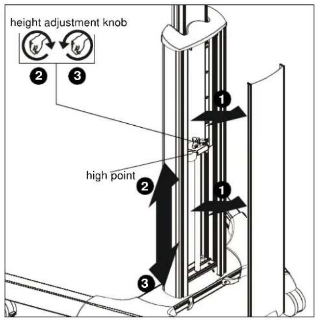
Figure 16

Figure 17
Pitch Adjustment
- Turn pitch adjustment knob clockwise to tilt display forward. (See Figure 18)
- Turn pitch adjustment knob counterclockwise to tilt display back. (See Figure 18)
Roll Adjustment
-
Turn roll adjustment knob clockwise to adjust roll to the left. (See Figure 18)
-
Turn roll adjustment knob counterclockwise to adjust roll to the right. (See Figure 18)

Figure 18
Cart Use and Maintenance

WARNING: Exceeding the weight capacity can result in serious personal injury or damage to equipment! It is the installer's responsibility to make sure the combined weight of all components located between the LPAU up to (and including) the display does not exceed 200 lbs (90.7 kg).

WARNING: RISK OF SERIOUS INJURY OR DEATH!
Placing a remote control or toy on the cart may encourage a child to climb onto the cart causing the cart to tip over onto the child. DO NOT place remote controls or toys on the cart!

WARNING: RISK OF SERIOUS INJURY OR DEATH!
Relocating audio and/or video equipment to the cart may result in the cart collapsing or overturning onto a child. DO NOT relocate audio and/or video equipment to the cart!

WARNING: CART CAN TIP OVER RESULTING IN INJURY! Do not allow children under 16 to move cart. Only adults should move this cart. Move cart slowly. Apply moving force on narrow dimension. Never apply force at top - always push toward the middle. Push, don't pull cart. (See Figure 19)
NOTE: The LPAU cart has no user serviceable parts.
NOTE: The LPAU cart can support screen sizes up to a maximum of 90" wide.
- Always place cart on a level surface.
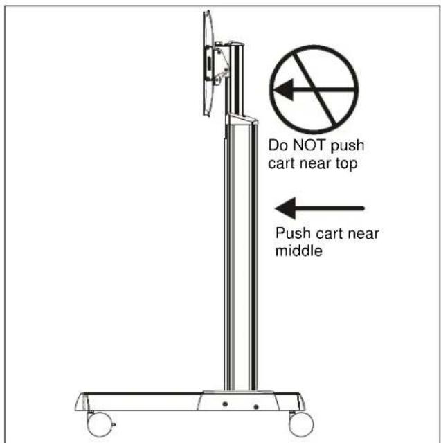
Figure 19
- Always lock the wheels when the cart is not moving.
- Check and tighten the hex nuts on the casters occasionally. (See Figure 20) These should be checked especially after use on uneven ground.

natural_image
Technical diagram of a mechanical component with a magnified inset showing a circular feature labeled 'x 4' (no text or symbols present)Figure 20
Removing Display from Cart
- Remove any padlocks from interface uprights if installed.
- Position latches on interface uprights so that they are in the "open" position. (See Figure 21)

WARNING: DISPLAYS MAY WEIGHT IN EXCESS OF 40 LBS! Always use two people and proper lifting techniques when installing or positioning display on cart.
- Carefully lift display from cart. (See Figure 21)

Figure 21
Brand : Chief
Model : LPAUS
Category : Media card