32 Express - Boat Regal - Free user manual and instructions
Find the device manual for free 32 Express Regal in PDF.


| Product Type | Express Cruiser Boat |
| Length Overall (LOA) | 32 ft (9.75 m) |
| Beam | 10.5 ft (3.20 m) |
| Draft (drives up/down) | 3 ft (0.91 m) |
| Dry Weight | 12,000 lbs (5,443 kg) |
| Fuel Capacity | 150 gal (568 L) |
| Water Capacity | 30 gal (114 L) |
| Holding Tank Capacity | 20 gal (76 L) |
| Engine Options | Twin MerCruiser or Volvo Penta gasoline sterndrives |
| Maximum Speed | 40 mph (35 knots) |
| Cruising Speed | 25 mph (22 knots) |
| Fuel Consumption (cruise) | 20 GPH (75.7 L/h) |
| Hull Material | Fiberglass |
| Accommodations | Sleeps 4-6 in V-berth and mid-cabin |
| Head | Enclosed with marine toilet and shower |
| Galley | Stainless steel sink, refrigerator, stove |
| Safety Equipment | Fire extinguisher, bilge pump, life jackets, throwable device |
| Maintenance | Regular engine oil changes, hull cleaning, winterization |
| Cleaning | Mild soap and water for gelcoat; avoid abrasives |
| Repairability | Common parts available through Regal dealers |
Frequently Asked Questions - 32 Express Regal
User questions about 32 Express Regal
0 question about this device. Answer the ones you know or ask your own.
Ask a new question about this device
Download the instructions for your Boat in PDF format for free! Find your manual 32 Express - Regal and take your electronic device back in hand. On this page are published all the documents necessary for the use of your device. 32 Express by Regal.
USER MANUAL 32 Express Regal
32 EXPRESS
OWNER'S MANUAL

Note
The information found in this owner's manual may change at any time.
Designated items referred to may not be installed on your vessel. In keeping with its commitment to continued product improvement Regal Marine Industries, Inc. reserves the right to modify the vessel at any time without notice including changes in specifications, colors, fabrics, materials and equipment or to discontinue a model. Regal is not obligated to make similar changes or modifications to models sold prior to the date of such changes.
All specifications are approximate including weights, fuel figures and speeds. Speeds are calculated at sea level with a temperature of 70 to 85 degrees. Increases in altitude and/or temperature will reduce horsepower and thereby reduce the speed of the vessel.
All information is for reference only and should be used as a guideline. Consult local and state guidelines as they may differ in your area. Any decisions relating to safe operation of the vessel are the responsibility of the operator.
REGAL®
Follow no one.
OWNER'S MANUAL
32 EXPRESS
1 INTRODUCTION
Regal Owner's Manual 1-4
Owner's Information Packet 1-4
General Information 1-5
Regal Marine Warranty 1-12
2 SAFETY ON BOARD
Safety Labels 2-1
General Boating Safety 2-2
Required Safety Equipment 2-4
Fire Extinguishers 2-6
Visual Distress Signals 2-7
Sound Protecting Devices 2-10
Radio Communications 2-10
Navigation Lights 2-10
Marine Sanitation Devices 2-10
Pollution Regulations 2-12
Garbage Discharge 2-13
Life Rafts 2-14
U.S.C.G Minimum Equipment Requirements 2-14
Exhaust & Carbon Dioxide 2-15
Boating & Alcohol 2-19
Boating Accidents/Federal Security Regulation 2-20
Water Sports 2-22
Weather & Water Conditions 2-23
3 RULES OF THE ROAD
Navigation Rules Defined 3-1
Navigation Rules 3-1
Bridge Clearance 3-8
4 SYSTEMS
Fuc1 4-2
Electrical 4-16
Generator 4-60
Air Conditioning 4-65
Fresh Water/Waste 4-69
Trim Tabs 4-83
Windlass 4-85
Entertainment 4-90
Electronics 4-106
5 ENGINE/CONTROLS
Break-In 5-2
Ventilation 5-3
Switches 5-4
Instrumentation 5-7
Starting- Before & After 5-9
Controls 5-11
6 VESSEL OPERATION
Getting Underway 6-1
Starting & Stopping 6-4
Fenders 6-5
Dock Line Basics 6-6
Knots 6-8
Docking 6-8
Anchoring 6-9
Towing/Admiralty Law 6-10
Emergencies 6-11
Environmental Awareness 6-14
Door-Cabin Entry 7-4
Gray Water 7-4
Hatches 7-5
Lighting 7-6
Monitor- Water/Waste 7-9
Port-Starboard Windows 7-10
Range 7-11
Refrigerator 7-12
Salon Table 7-15
Seat-Helm 7-16
Television 7-17
Vacuum Cleaner
EXTERIOR EQUIPMENT
Antennac 7-21
Bilge Pump/Float 7-22
Door-Transom 7-23
Electronics 7-24
Fire Extinguisher- Automatic 7-25
Generator 7-27
Hatch-Engine 7-28
Heater-Hot Water 7-29
High Water Alarm 7-30
Markers- For Slings 7-31
Overboard Discharge Pump 7-32
Power Tower 7-33
Pump-Fresh Water 7-35
Satellite Radio 7-36
Shower-Transom 7-37
Spotlight 7-38
Sunpad Lounge- Fwd. Deck 7-39
Swim Ladder 7-40
Swim Platform 7-41
Thruster 7-42
Ultra Sun Lounge- Aft 7-44
Underwater Lighting 7-45
8 COSMETIC CARE & MAINTENANCE
Cosmetic Care 8-1
Maintenance 8-20
9 TROUBLESHOOTING
Diagnostic Charts 9-1
10 STORAGE & WINTERIZATION
Checklists 10-2
11 GLOSSARY & INDEX 11-1
12 TECHNICAL
Technical Information 12-1
Technical Drawings 12-6
Introduction

Your Regal dealer can provide information regarding national training organizations such as the U.S. Power Squadron and United States Coast Guard Auxiliary. Along with other organizations and literature, they can help build your “boating savvy” by developing the necessary skills and awareness to be a safe and confident skipper.
Also, your local library can assist in providing recommended boating literature such as Chapman Piloting Seamanship & Boat Handling by Elbert S. Maloney.
Also, boating information is available on the internet. Remember, waterway conditions can change in a heartbeat. Knowing how to react quickly comes from experience and knowledge which can be gained through boating education. Welcome aboard!
Boating is becoming more popular each and every year. There are numerous types of recreational vessels on our waterways today involved in an every growing number of activities. Therefore, as a Regal boat owner it is of the highest priority to learn about general boating practices before operating your vessel.
Your Regal dealer will answer many questions and provide valuable “hands on” information during the completion of the new boat delivery process. In addition, your dealer has received special factory training on the product line and his services should be employed to solve any technical problems and periodic maintenance beyond the scope of this manual. Your Regal dealer carries a line of factory approved parts and accessories.
It is important that you read the engine operator's manual carefully and become completely familiar with the operation as well as required maintenance procedures on the engines and related propulsion systems. Also, read the auxiliary equipment manuals found in the owner's information packet.
WELCOME TO REGAL
I know I speak for everyone at Regal when I welcome you to the ever-growing family of Regal boat owners. You've chosen a boat that is recognized worldwide for its standard of excellence. Each step in construction has been carefully scrutinized to assure safety, performance, reliability and comfort for both your passengers and yourself.
Your yacht is certified by the National Marine Manufacturers Association. It also complies with the applicable standards set by the United States Coast Guard, American Boat and Yacht Council and the International Marine Certification Institute. Your Regal boat was built with the same attention to detail and quality of construction that we would expect in a craft we would purchase ourselves.
Whether you're a veteran boater or a newcomer, we strongly urge you to read this owner's manual thoroughly. Familiarize yourself with the various components of your vessel, and heed the safety precautions noted herein.
If you have questions that are not covered in this manual, please consult your authorized Regal dealer for assistance, phone the Regal factory at 407-851-4360 or E-mail us at www.regalboats.com.
Thank you, and welcome to the "World of Regal!"
Duane Kuck
President & CEO
REGAL MARINE INDUSTRIES, INC. MISSION STATEMENT
With God's help
and a steadfast commitment to integrity,
we will develop a team
of exceptional people and relationships
to provide exceptional customer satisfaction.
OWNER'S PACKETREGAL OWNER'S
Your Regal owner's manual has been compiled with information to assist you in operating your craft with safety and pleasure. This manual targets specific details of Regal related systems and components along with their location, operation and maintenance that normally is not found in the vendor information. In addition, supplier related equipment information is located within the owner's information package.
An owner's information packet (black satchel) is located on the vessel. Read and become familiar with the materials. This packet contains valuable literature on your propulsion package, standard and optional equipment, systems, various care and cleaning instructions along with component warranty and instructional information.
Store the information packet in a clean, dry location.

The Regal owner's manual is not to be thought of as a complete shop technical document. Beside the system chapters, there is troubleshooting information devoted to select current standard and optional equipment. In addition, refer to the engine and generator (if installed) operator's manuals. More detailed information may exist in the owner's packet associated with that component.
Remember that your Regal dealer has received special factory training and his services should be employed to solve more technical problems. Call 407-851-4360 or go to the internet at www.RegalBoats.com to find the closest Regal dealership.
In keeping with its commitment to improvement Regal Marine Industries, Inc. is continually upgrading the product line. Regal notes that all dimensions, specifications, models, standard and optional equipment is subject to change without notice at any time.
GENERAL INFORMATION
HULL IDENTIFICATION NUMBER (HIN)
The United States Coast Guard has established a universal system of numerically recognizing vessels by using a hull identification number or “HIN.” This number identifies your Regal yachts’ model, hull number, month and year of manufacture. The HIN is normally found on your boat’s transom, on the starboard side, just below the rub rail on the transom vertical surface. The HIN is stamped on a pla and reinforced with a special adhesive. The HIN consists of 12 alpha or numeric characters.
It is recommended that you locate and write down the HIN for future reference. It can be especially useful when ordering parts from your Regal dealer. A second HIN number is found in a hidden location. This second HIN is useful to authorities if the vessel is stolen and/or the original transom HIN is modified or eliminated.
VESSEL INFORMATION SHEET
It is recommended that you fill out the information on the following page. It will supply vital statistics on your vessel. Make a copy of the data for safe keeping at home.
VESSEL FLOAT PLAN
Formulate the float plan on the following page before departing. Leave it with a responsible person who will notify the United States Coast Guard or local law enforcement authorities if you do not return as planned. If you change your plans be sure to notify this person. Make copies of the float plan and use one each time you go boating. This will help people know where to find you should you not return on schedule. Do not file the float plan with the United States Coast Guard.
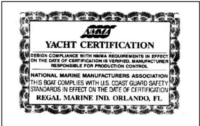
NMMA YACHT CERTIFICATION PLATE
HULL IDENTIFICATION NUMBER

At the helm (dash) area you will notice a metal plate which recognizes that your vessel was built to design compliance in effect on the date the certification was verified. The plate also states that your vessel complies with U. S. Coast Guard safety system standards in effect on the date of certification. Vessels 26' and longer are candidates for the NMMA Yacht Certification Plate.
VESSEL INFORMATION
Owner:
Address:
City & State:
Home Phone: ____ Business Phone: ____
In Case Of Emergency Notify:
Address
City State
Phone
Insurance Agent's Name: ____
Policy#:
USCG Phone: ____ Local Police: ____
Marina Phone: ____ Slip (Dock#): ____
Hull Serial #: RGM____
Key #:____ Port Engine:____ Stbd Engine:____
Key #:____ Cabin Door: ____
Selling Dealer:
Address:
City & State:
Phone: ____ Fax: ____
Servicing Dealer:
Address:
City & State:
Phone:____ Fax:____
VESSEL FLOAT PLAN
Fill out this form before departure. Leave it with a responsible person who will notify the Coast Guard or police if you don't return as planned. If you change your plans be sure to notify this person. Make copies of the float plan and use one each time you go on a trip. This will help people know where to find you should you not return on schedule. Do not file this plan with the Coast Guard.
Owner:
Address:
City & State: ____
Telephone#: ____ ____
Person Filing Report: ____
Name ____
Telephone ____ ____ ____
Make Of Craft:
Length____Boat Name____
Color____ Trim____ Hp____
Inboard ____ Stern Drive ____
Hull I.D.#
Documented Vessel # ____ ____
Other Information ____ ____________ ____________
Safety Equipment Aboard:
Life Jackets First Aid Kit
Flares Flash Light VHF Radio Cell Phone #_ Computer _Desk Top _Lap Top_ E-mail address_ Food Water_
State Registration#
Destination: Leave From ____ Time Left ____ Going To ____
Fuel Capacity ____
Est. Day Of Arrival ____ ____
Est. Time Of Arrival ____ If Not Back By ____ o'clock Call Authorities
Persons Aboard:
Name Age Address
Phone
See Other Side For Additional Persons
VESSEL CRUISE CHECKLIST
☐ Obtain a current w eather update.
☐ Periodically hoist the boat & inspect the hull bottom and propellers for damage. Marine growth such as barnacles will affect performance and fuel efficiency. Check sacrificial anodes located on the propulsion unit, transom and engine. Replace anode if less than 2/3 remaining.
☐ Check the electrical system and all safety related equipment. Carry extra fuses. Ensure they are of the proper capacity and type.
☐ If your boat has been in the water, run the bilge pump until the flow of water stops.
☐ If your boat has been out of the water, check to see that all bilge water has drained.
☐ Check that all required safety equipment is on board and in good working condition. Examples include personal flotation devices (PFD's), horn, bell, hand held fire extinguishers, and visual distress signals.
☐ Check fuel level. Fuel tanks should be filled to slightly less than capacity. Allow for fuel expansion. Remember the “one third rule”.
☐ Open engine compartment. Inspect for fuel odors and visible leaks in the fuel, oil, coolant, exhaust and power steering systems.
☐ Check the fuel filters for the presence of water.
☐ Check fluid levels of engines, drives and generator.
□ Visually inspect engine for cracked hoses, worn or loose belts, and loose hardware.
RECOMMENDED ON BOARD EQUIPMENT
TOOLS
SPARE PARTS
Allen Wrenches Fuel Filters-Engines & Generator
Jack Knife Poly V-Belt (See Engine Manual)
Phillips Screwdriver Coolant For Engine Freshwater
System Extra Light Bulbs
Regular & Needle Nose Pliers Seawater Filter
Combination Box & End Wrench Set Fuses
Screwdriver Set (One With Various Tips) Propeller Set (See Dealer)
Side Cutters Propeller Hardware
Ratchet & Socket Set Flashlight Batteries
Electrical Crimper, Cutter, Stripper Combo Engine Spare Parts
Hammer Generator Spare Parts
VOA Electrical Tester Air Filters-Engine & Generator
Water Pump Pliers Oil Filters-Engine, Generator
Vise Grip Pliers Drive Oil Filters
Floating Flashlight/Lantern
Oil/Fuel Filter Wrench
Tape Rule
BASIC GEAR & SUPPLIES
BASIC GEAR & SUPPLIES
Tow Line Lubricating Oil, Liquid Wrench
Mooring Lines Duct & Electricians Tape
Dock Fenders Coolant (Engine Freshwater Side)
Distress Signals Engine, Drive, Power Steering Oil
First Aid Kit Boat Soap (Not Dish Soap)
Boat Hook Woody Wax
Charts & Plotting Instruments/Back-up Use Vinyl Cleaner
Emergency Food & Water
EPIRB Life Raft
Bailer or Hand Pump Rust Stain Remover (Starbrite)
Extra Hand Held Fire Extinguishers Corrosion Block
Personal Floatation Devices Bilge Cleaner
Clean Rags, Diapers (For Under Engine-Oil Leaks)
Sunscreen (SPF 30+) Shop Vac (1 Gal. Cap. Wet-Dry)
Bucket/Pans w/Lids-Draining/Storing Used Fluids Squeegee
Mirror (For Inspection & Emergency Signaling)
Funnel
Hydrogen Peroxide (AC Pans)
Nylon Windbreaker Suit
Binoculars
Owner's Registration & Systems Dealer's Responsibility Checklist
Please note that your boat requires the proper registration by Your vessel has undergone rigid quality assurance your authorized Regal dealer. To initiate the vessel warranty inspections before leaving the factory. In addition, your your dealer must complete the owner's registration form dealer has been trained to perform final pre-delivery checks and systems checklist at the time of delivery. The owner and to service your Regal boat.
has reviewed the boat systems and warranty provisions withYour dealer's responsibilities include:
the owner. The owner should keep the original paperwork that features a temporary warranty registration. A warranty certifi cate will be sent approximately 6 weeks after receipt of the paperwork at Regal World Headquarters.
-
An orientation in the operation of your Regal boat including matters relating to the safe operation of the vessel.
-
Completion and mailing of your boat registration warranty form to Regal.
-
Location of vendor warranties, registration materials, owner's manual, operation, installation and maintenance instructions for auxiliary equipment supplied with or installed on your Regal boat.
Owner's Responsibility
You are entitled to all the benefits and services outlined in your Regal warranty. However, you have certain responsibilities to ensure warranty satisfaction.
These are:
To read the warranty materials and understand them fully.
To examine the vessel in detail at the time of delivery.
Apply the following: boating rules and regulations, safety equipment, environmental regulations, accident reports and warranty regulations terms and conditions.
To read thoroughly all literature supplied with your boat including this owner's manual and to follow the recommendations in the literature.
To provide proper maintenance and periodic servicing of your boat and equipment as set forth in the various manuals supplied.
Customer Service
Take the time to write down your Regal dealer's phone number and E-mail address for future reference. Along with your Regal dealer information is a listing below of other phone numbers and web addresses which may prove useful.
Regal Dealer:
Phone:
E-mail:
Regal Marine Customer Service:
1-800-US REGAL (1-800-877-3425)
regal@regalboats.com
customer.service@regalboats.com
Volvo Penta Of America (24-Hour Hotline Support):
1-800-522-1959
vpa.consumerrelations@volvo.com
REGAL MARINE INDUSTRIES, INC. LIMITED WARRANTY
Welcome to the Worldwide Family of Regal Owners! We are very pleased that you have chosen a Regal Powerboat!
This document is your Warranty Registration Certificate and Statement of Warranty. Please check the registration information section for accuracy. If this information is not correct or if you change your address at some future date, please notify us at the following address: Regal Marine Industries, Inc. Attention: Warranty Registrations, 2300 Jetport Drive, Orlando, Florida 32809; or E-mail at customer.service@regalboats.com.
Please read the warranty carefully. It contains important information on Regal's claims procedures and your rights and obligations under this warranty.
WHAT IS COVERED: This Limited Warranty applies only to Regal boats beginning with model year 2008.
LIFETIME LIMITED STRUCTURAL HULL WARRANTY: Regal Marine Industries, Inc. warrants to the original retail purchaser of this boat if purchased from an authorized Regal dealer that the selling dealer or Regal will repair or replace the fiberglass hull if it is found to be structurally defective in material or workmanship for as long as the original retail purchaser owns the boat. For purposes of this warranty, the hull is defined as the single fiberglass casting which rests on the water. This limited warranty is subject to all limitations and conditions explained below.
FIVE-YEAR TRANSFERABLE LIMITED STRUCTURAL HULL WARRANTY: In addition to the Lifetime Limited Structural Hull Warranty, Regal offers a Transferable Five-Year Limited Structural Hull Warranty. Under the Five-Year Transferable Limited Structural Hull Warranty, Regal will repair or replace the fiberglass hull if it is found to be structurally defective in material or workmanship within the first (5) years after the date of delivery to the original retail purchaser. Any remaining term of this Five-Year Limited Hull Warranty may be transferred to a second owner if within 60 days of purchase, the new owner registers the transfer with Regal and pays the established warranty transfer fee. Contact Regal Customer Service at the above address for details.
FIVE-YEAR LIMITED HULL BLISTER WARRANTY: Regal warrants that the selling dealer or Regal will repair any underwater gelcoated surfaces of the hull against laminate blisters which occur as a result of defects in material or workmanship within (5) years of the date of delivery, provided that the original factory gecoat surface has not been altered. Alternation would include but is not limited to damage repair; excessive sanding, scraping, sandblasting; or from improper surface preparation for application of a marine barrier coating or bottom paint, any of which shall void this Five-Year Limited Hull Blister Warranty. Proper preparation must be applied to the hull bottom if the boat is to be moored in the water for periods in excess of sixty (60) days. Regal Marine shall repair or cause to be repaired any covered laminate blisters based on the following prorated schedule.
Less than two (2) years from delivery date - 100%, Two (2) to three (3) years from delivery date - 75%, Three (3) to four (4) years from delivery date - 50%, Four (4) to five (5) years from delivery date - 25%. Reimbursement shall be limited to one repair, not to exceed one hundred (\$100.00) dollars per foot of boat length prior to prorating. Regals prior authorization for the method and cost of repair, must be obtained before repairs are commenced. All costs to transport the boat for repairs are the responsibility of the owner.
LIMITED GENERAL WARRANTY: In addition to above hull warranties, Regal warrants to the original purchaser of this boat if purchased from an authorized Regal dealer that the dealer or Regal will repair or replace any parts found to be defective in materials or workmanship for a period of one (1) year from the date of delivery, subject to all exceptions, limitations and conditions contained herein.
LIMITED EXTERIOR FINISH WARRANTY: Regal warrants that the selling dealer or Regal will repair cosmetic defects in the exterior gelcoated finish including cracks or crazing reported to Regal within 90 days from the date of delivery to the original retail purchaser, subject to all limitations and conditions contained herein. All warranty work is to be performed at a Regal dealership or other location authorized by a Regal Customer Service Manager after it is established to Regal's satisfaction that there is a defect in material or workmanship.
REGISTRATION INFORMATION:
CUSTOMER OBLIGATIONS: The following are conditions precedent to the availability of any benefits under these limited warranties:
(a) The purchaser must sign and the dealer must submit to Regal the "NEW BOAT DELIVERY CHECKLIST" within ten (10) days of the date of delivery and such information must be on file at Regal.
(b) The purchaser must first notify the dealer from whom the boat was purchased of any claim under this warranty within the applicable warranty period and within a reasonable period of time (not to exceed thirty (30) days) after the defect is or should have been discovered; and (2) if such continued use causes other or additional damage to the boat or component parts of the boat.
(c) Regal will not be responsible to repair any condition or replace any part, (1) if the use of the boat is continued after the defect is or should have been discovered; and (2) if such continued use causes other or additional damage to the boat or component parts of the boat.
(d) Based on the dealer's knowledge of Regal's warranty policy and/or consultations with Regal, the dealer will accept the claim and arrange for appropriate repairs to be performed, or deny the claim if it is not within the warranty.
(e) The dealer will contact the Regal boat owner regarding instructions for delivery of boat or part for warranty repair if it is covered by the limited warranty.
ALL COSTS TO TRANSPORT THE BOAT FOR REPAIRS ARE THE RESPONSIBILITY OF THE OWNER;
(f) If the Regal boat owner believes a claim has been denied in error or the dealer has performed the warranty work in an unsatisfactory manner, the owner must notify Regal's Customer Service Department in writing at the address listed for further consideration. Regal will then review the claim and take appropriate follow-up action.
WARRANTY EXCEPTIONS: THIS LIMITED WARRANTY does not cover and the following are not warranted:
(a) Engines, metal plating or finishes, windshield breakage, leakage, fading and deterioration of paints, canvas, vinyl, upholstery and fabrics;
(b) Gelcoat surfaces including, but not limited to, cracking, crazing, discoloration or blistering except as noted above;
(c) Accessories and items which were not part of the boat when shipped from the Regal factory, and/or any damage caused thereby;
(d) Damage caused by misuse, accident, galvanic corrosion, negligence, lack of proper maintenance, or improper trailering;
(e) Any boat used for racing, or used for rental or commercial purposes;
(f) Any boat operated contrary to any instructions furnished by Regal, or operated in violation of any federal, state, Coast Guard or other governmental agency laws, rules, or regulations;
(g) The limited warranty is void if alterations have been made to the boat;
(h) Transportation of boat or parts to and/or from the REGAL factory or service location;
(i) Travel time or haul outs, loss of time or inconvenience;
(j) Any published or announced catalog performance characteristics of speed, fuel and oil consumption, and static or dynamic transportation in the water;
(k) Any boat that has been repowered beyond Regal's power recommendations;
(1) Boats damaged by accident and boats damaged while being loaded onto, transported upon or unloaded from trailers, cradles, or other devices used to place boats in water, remove boats from water or store or transport boats on or over land;
(m) Water damage to, dry rot to, condensation to, or absorption by interior surfaces, wood structures or polyurethane foam;
interior wood including, but not limited to, bleeding and/or discoloration as a result of condensation or moisture or water continually contacting the plywood causing staining to upholstery, carpet or other interior surfaces;
(n) Costs or charges derived from inconveniences or loss of use, commercial or monetary loss due to time loss, and any other special, incidental or consequential damage of any kind or nature whatsoever.
NO WAVIER OF THESE ITEMS: The terms, conditions, limitations and disclaimers contained herein cannot be wavered except by the Customer Service Manager of Regal. Any such wavier must be in writing. Neither the dealer, nor the customer, nor any service, sales and/or warranty representative of Regal is authorized to waive and/or modify these conditions, limitations and/or disclaimers.
GENERAL PROVISIONS:
ALL GENERAL, SPECIAL, INDIRECT, INCIDENTAL AND/OR CONSEQUENTIAL DAMAGES ARE EXCLUDED FROM THIS WARRANTY AND ARE TOTALLY DISCLAIMED BY REGAL. IT IS THE INTEREST OF THE PARTIES THAT THE OWNER'S SOLE AND EXCLUSIVE REMEDY IS THE REPAIR OR REPLACEMENT OF THE VESSEL OR ITS ALLEGEDLY DEFECTIVE COMPONENT PARTS AND THAT NO OTHER LEGAL OR EQUITABLE REMEDIES SHALL BE AVAILABLE TO SAID OWNER. SOME STATES DO NOT ALLOW THE EXCLUSION OF INCIDENTAL OR CONSEQUENTIAL DAMAGES SO THE FOREGOING MAY NOT APPLY TO YOU. THIS IS A LIMITED WARRANTY; REGAL MAKES NO WARRANTY, OTHER THAN CONTAINED HEREIN;
TO THE EXTENT ALLOWED BY LAW ANY WARRANTIES OF MERCHANTABILITY OR FITNESS FOR A PARTICULAR PURPOSE ARISING IN STATE LAW ARE EXPRESSLY EXCLUDED TO THE EXTENT ALLOWED BY LAW. ANY IMPLIED WARRANTY OF MERCHANTABILITY IS LIMITED TO THE PERIOD OF THIS LIMITED WARRANTY. ALL OBLIGATIONS OF REGAL ARE SPECIFICALLY SET FORTH HEREIN. REGAL DOES NOT AUTHORIZE ANY PERSON OR DEALER TO ASSUME ANY LIABILITY IN CONNECTION WITH REGAL BOATS. Some states do not allow limitations on how long an implied warranty lasts, so the above limitation may not apply to you. Regal's obligation with respect to this warranty is limited to making repairs to or replacing the defective parts and no claim for breach of warranty shall be cause for cancellation or rescission of the contract or sale for any boat manufactured by REGAL MARINE INDUSTRIES, INC.
Regal will discharge its obligations under this warranty as rapidly as possible, but cannot guarantee any specific completion date due to the different nature of claims which may be made and services which may be required. Regal reserves the right to change or improve the design of its boats without obligation to modify any boat previously manufactured. This limited warranty gives you specific legal rights, and you may also have other rights which may vary from state to state. Regal shall in no way be responsible for any repairs not PRE-AUTHORIZED by a Regal Customer Service Manager or repairs performed by a repair shop not PRE- AUTHORIZED by a Regal Customer Service Manager.
Safety On Board

Safety awareness can not be over emphasized. Safety on board needs to be the skippers number one priority. In this manual you will find many safety precautions and symbols to identify safety related items. Heed all safety precaution information. Remember, the skipper is responsible for the safety of his passengers and crew.
SAFETY LABELS
SAFETY PRECAUTION DEFINITION
Safety precautions are stated as caution, warning and danger signal words. They are highlighted in this manual by font design and symbol usage. Also, a notice heading is included which provides operation and maintenance information but is not hazard-related. An information label provides tips on a variety of topics. Become familiar and understand all safety precaution labels!

WARNING
Potentially hazardous situation that, if not avoided, could result in death or serious injury.
CAUTION
Indicates a potentially hazardous situation or unsafe practice that, if not avoided, may result in injury, property or product damage.
NOTICE
General or specific information which is important to correct operation or maintenance, but is not hazard related.

DANGER
Immediate hazardous situation that, if not avoided, will result in death or serious injury.

INFORMATION
Educational tips for the skipper and crew.
PRECAUTIONARY LABELS
Read and understand all safety labels affi xed to your Regal boat or found in this manual and the vendor literature.
Many of the safety labels are posted close to the helm, aft cockpit, cabin and swim platform. The location of the labels may vary.
Review the helm safety labels with passengers before disembarking.
Use common sense to analyze the result of an action on board your vessel. Always think safety first!
NOTICE
DO NOT REMOVE OR COVER ANY PRECAUTIONARY LABELS.
KEEP HARSH CHEMICALS AWAY FROM LABELS.
IF A LABEL BECOMES ILLEGIBLE, CONTACT YOUR REGAL DEALER FOR ORDERING REPLACEMENTS.
GENERAL BOATING SAFETY
We understand that you are eager to go boating. However, we strongly suggest that you thoroughly familiarize yourself and friends or members of your family with safe boating practices before setting out.
Remember, that along with the freedom and exhilaration of boating comes the responsibility that you have for the safety of your passengers and other boaters who share the water with you.
Boating regulations vary from state to state. Check with your local state and local authorities for the regulations pertaining to your area.
Check with local FM weather stations, U. S. Coast Guard, or on-line for the latest weather conditions. Remember getting caught in severe weather is hazardous. Check weather conditions periodically while you are boating. If you are forced to operate your boat in a storm condition, take common sense precautions; wear PFD's, store gear, reduce speed and if possible head for safe refuge.
It is best to avoid operating your boat in foggy weather. When fog sets in, take bearings, log courses and speeds.
You are required to emit a fi ve second blast from your horn or whistle once every minute. Also, have your passengers wear PFD's and observe for oncoming vessels.
Operation in shallow water presents a number of hazards including sand bars and water levels influenced by tides. If the vessel strikes an underwater hazard, check for boat and engine damage. If the engine vibrates excessively after striking an underwater obstruction, it may indicate a damaged propeller. If you run aground, seek help by radio or flares.
Make sure your boat and equipment are in top condition. Do this by frequently inspecting the hull, engine and propulsion components.
You must provide a Coast Guard approved personal fl otation device (PFD) for every person on board. These PFD's should be in good condition and easily accessible.
Insist that non-swimmers and children on board wear a PFD at all times. If you encounter rough weather conditions, make sure everyone on board is wearing a PFD, including yourself. Instruct your passengers in how to put on their PFDs and be sure they know their storage location on the boat. Remember, in an emergency, a PFD that cannot be quickly located and worn is useless.
Never allow anyone to sit anywhere on the boat not specifi cally designed as seating. While underway, ALWAYS insist passengers sit in a seat and set an example by doing this yourself.

Never drink and drive! As captain, you are responsible for the safety of your passengers. Alcohol and boating can be a dangerous combination. DO NOT mix them. Alcohol impairs the boat operators ability to make conscious decisions and react
to emergency situations quickly.
Never overload your boat! An overloaded boat, or one with uneven weight distribution can be difficult to steer.
Use maximum caution when fueling. Never allow any smoke or flame nearby while you are fueling. ALWAYS check for fuel leaks and fumes when fueling is completed.
Be certain there is enough fuel aboard for your cruising needs. Include any reserve that might be needed should you change your plans due to weather or an emergency. Practice the “one-third rule: Use one-third of your fuel going out, one-third to
return and retain one-third as a reserve.
Always check the weather before departure. Be particularly cautious of forecasted electrical storms and high winds.
Always have up-to-date charts aboard as a back-up to your plotter and auto pilot option. Charts can be obtained at your closet marina, on-line store or by contacting one of three federal government agencies.
Always file a float plan. Leave details of your trip with someone responsible who will be remaining on shore. Include expected return, plus name and phone number of a contact person in case of emergency.
Use care, courtesy and common sense when launching, docking or operating your boat.
Learn and obey the “Rules of the Road”. A weather resistant placard copy of the “Rules of the Road” is included in the on board Regal information packet. Additional information can be obtained from the U.S. Coast Guard Auxiliary or your local Power Squadron organization. In case of emergency know the international distress signals for your VHF radio. The spoken word “MAYDAY” is the international signal of distress and is for emergency use only. Under no circumstances should this word be used, unless there is danger at hand.
Posted speed limits, swimming areas, “no wake” zones and other restrictions should be red-fl agged. They are so noted for a reason. Sensible boat use, plus courtesy, equals enjoyable and safe boating.
It is your responsibility to stay abreast of all federal, state and local rules, as some laws or regulations may change or be different from state to state. Contact your local boating agencies for updated information.
We can not stress safety enough! Remember, there are no brakes on your boat, and the water current and wind velocity both affect your ability to respond. The operator must use caution at all times to maintain control of his vessel and especially to keep a safe distance from other boats and obstacles.
Always keep all safety gear in optimum condition. Pay special attention to attached tags and plates indicating expiration dates on equipment such as fire extinguishers, and personal flotation devices. Encourage a periodic maintenance check on all safety equipment. Contact your Regal dealer or marine professional for more information. Again, remember that the captain is responsible for his crew, passengers and vessel.
REQUIRED SAFETY EQUIPMENT
PERSONAL FLOTATION DEVICES
All personal flotation devices (PFD's) must be Coast Guard approved, in good working condition, and must be the correct size for the wearer. All PFD's must be readily accessible. This means being able to wear them in a reasonable amount of time in case of an emergency (fi re, boat sinking, etc.). They should not be stored or locked in closed areas. Also, make sure that all coverings are removed such as plastic from any PFD's. Throwable devices such as a ring buoy need to be available for immediate deployment. A PFD should be worn at all times when your boat is operating on the water. A PFD may save your life, but it must be worn to do so.
As a minimum U. S. Coast Guard requirement all recreational boats must carry one type I, II, III, or V PFD (wearable) for each person aboard. See the explanation following for each type. For type V to be counted they must be used according to the label instructions. In addition, all boats over 16' must carry one Type IV (throwable) PFD.
Some states require that PFD's be worn by children of specific ages at all times. Check with local and state boating agencies for particular requirements in your state before taking children on the water. Child life jackets are classified by the child's weight and should like all life jackets be sized before being purchased.
Remember PFD's will not necessarily keep you from drowning, even though they are designed to keep a person from sinking. When purchasing PFD's make sure it safely fi ts the person wearing it. It is a good idea to test PFD's in a lifeguarded shallow pool before venturing on the water.
Refer to the USCG minimum equipment requirements at the end of this chapter. It is meant to be a guide only. Contact state and local agencies for additional equipment requirements. Remember as the captain of your vessel you are responsible for its safe operation.

TYPE I- Also known as an offshore jacket, it provides the most buoyancy. It is a PFD for all waters and is especially useful in rough waters where rescue may encompass additional time. It is designed to turn most unconscious users in the water to a true face-up position. Type I PFD is available in adult & child sizes Buoyancy minimum poundages are 15.5 adult, 11 medium child, and 7 for small child and infants.

TYPE II PDFL
BUOYANT VEST
TYPE II- Also known as near-shore buoyant vest, it is recommended for calm, inland water where rescue time will be minimal. It will turn some unconscious people face-up in the water but not as numerous as Type I. They use the same buoyancy minimum poundages as the type I PFD's.

TYPE III- Known as a fl otation aid it is good for calm, inland water or where there is a chance for quick rescue. It is designed so wearers can place themselves in a face-up position in the water. The wearer may have to tilt their head back to avoid face-down positions.
Type III offer the same buoyancy minimum poundages as the Type II. They are generally the most comfortable for continuous wear. Float coats, fi shing vests, and vests featuring designs for various sport activities are examples of Type III.
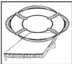
TYPE IV- Intended for calm, inland water with heavy vessel traffic, where help is constantly present. It is designed to be thrown into the water for someone to grab on to and held until rescued. It is not designed to be worn. Type IV includes ring buoys, buoyant cushions, and horseshoe buoys.

TYPE V- Also known as a special use device this is the least bulky of all PFD's. It contains a small amount of inherent buoyancy, and an inflatable chamber. It is rated even to a Type I, II, or III PFD (as noted on the jacket label) when inflated. Some Type V devices provide significant hypothermia protection. Varieties include deck suits, work vests, board sailing vests and Hybrid PFD's. Remember that this Type V type PFD may be carried instead of another PFD only if used according to the approval condition on the label.
Note: A water skier or wakeboarder is considered on board the vessel and a PFD is required for the purposes of compliance with the PFD carriage requirements. It is advisable and recommended for a skier or wakeboarder to wear a PFD designed to withstand the impact of hitting the water at a high speed. "Impact Class" marking on the label refers to PDF strength, not personal protection. Some state laws require a skier or wakeboarder to wear a PFD.
PFD'S FOR PETS
If you are a skipper who needs to have his pet dog or cat on board or dockside then a PFD is recommended. The PFD
will aid you in finding the pet if it should fall overboard. The device must fit the pet properly. Also, it may take a bit of training before the pet is comfortable wearing the PFD. Normally, dogs are easier to train wearing a life vest than a cat.
Marine type retail stores will fit a pet to a PFD by body weight.
MAINTAINING YOUR PFD'S
A PFD is only useful if it is well maintained. Always be aware of PDF age since it has a life expectancy like any other piece of equipment.
√ Check periodically for broken zippers, frayed webbing, water soaked kapok bags, missing straps, and sewing that has become undone.
√ Clean each PFD with mild soap and water only. Again, let dry sufficiently before storing.
√ Keep PFD's out of grease and oil since they can deteriorate the jacket inner and outer materials.
√ Check any kapok-bagged jackets by squeezing. If you hear air escaping the bag is defective and the PFD should be thrown away.
√ Grab the cover with the fingers. If the cover material rips, the PFD is rotted and should be thrown away.
√ If the kapok bag is hard the PFD should be discarded.
FIRE EXTINGUISHERS
GENERAL INFORMATION
Fire extinguishers are classified by a letter and numeric symbol. The letter references the type of fire the unit is designed to extinguish.
For example, type B extinguishers commonly used on boats are designed to put out fl ammable liquids such as grease, oil and gasoline.
The number indicates the general size of the extinguisher (minimum extinguishing agent weight).
Coast Guard Approved extinguishers are identified by the following marking on the label:
"Marine Type USCG Approved, Size..., Type..., 162.028/.../", etc.
| FIRE EXTINGUISHER CONTENTS | ||||
| CLASS | FOAM IN GALS. | C02 IN LBS. | DRY CHEM IN LBS. | HALON IN LBS. |
| B-I | 1.25 | 4 | 2 | 2.5 |
| B-II | 2.5 | 15 | 10 | 10 |
| MINIMUM PORTABLE FIRE EXTINGUISHERS REQUIRED | |||
| VESSEL NO | FIXED | WITH | FIXED |
| LENGTH | SYSTEM | SYSTEM | |
| LESS THAN 26' | 1 B-1 | 0 |
| 26' TO LESS THAN 40' | 2 B-1 OR 1 B-II | 1 B-1 |
| 40' TO 65' | 3 B-1 OR 1 B-1 & 1 B-II | 2 B-1 |
| OR 1 B-2 |
U. S. Coast Guard approved fire extinguishers are needed on all Regal boats. Besides the minimum Coast Guard requirements always check state and local agencies for additional requirements and equipment.
Coast Guard approved extinguishers are hand-portable, either B-I or B-II classification. U. S. Coast Guard approved hand-portable and semi-portable extinguishers contain a metal plate that shows the manufacturers name and extinguisher type, capacity and operating instructions. They have a special marine type mounting bracket which keeps the extinguisher solidly mounted until needed. The extinguisher needs to be mounted in a readily accessible location but one that will not be bumped by people while underway. All approved extinguishers shall have an indication gauge.
U.S.C.G APPROVED FIRE EXTINGUISHER TYPES & FEATURES
■ The carbon dioxide unit uses CO2 gas under high pressure, with a funnel discharge hose usually swivel mounted. This extinguisher leaves no residue and does not cause interior engine harm. To ensure workability, weigh the unit annually. A 10% maximum weight variance
is allowed.
Another type of liquifi ed gas used today is FE-241. This gas is colorless and odorless, heavier than air and sinks to the lower bilge to extinguish fi res. Since the year 2000 ingredients have changed to a more environmental friendly formula (Chlorotetrafl uoroethane or FE-241). FE-241 is used in portable-hand units along with making up the majority of boat automatic fi re extinguishing systems. The canister needs to be weighed once a year. These clean agent units feature a dash mount indicator.
Refer to the information regarding fi re prevention in this manual.

VISUAL DISTRESS SIGNALS
The dry chemical agent is widely used because of its convenience and low cost. The extinguisher canister is filled with a white dry chemical powder along with a pressurized gas. It is a good idea to shake this type periodically because they tend to "pack" on the canister bottom.
All vessels used on coastal waters, any of the GreItakes, territorial seas, and those waters connected directly to them up to a point where a body of water is less than two miles wide, must be equipped with Coast Guard approved visual distress signals.
Vessels owned in the United States operating on the high seas must be equipped with U.S.C.G. approved visual distress signals.

■ The foam type uses a chemical foaming agent plus water and is best when used for fi res involving fi ammable liquids- solvents, gasoline, oil, grease and various paints. It will work on fi res involving rubber, plastics, cloth, wood, and paper. It
leaves a messy residue. Do not use this extinguisher for electric fi res.
VISUAL DISTRESS SIGNALS
PYROTECHNIC DEVICES
Pyrotechnic visual distress signals must be Coast Guard approved, be ready for service and must be readily accessible. They all display a marking which is the service life, which must not have expired. A minimum of 3 devices are required for the day and 3 devices for night.
Some devices meet both day and night requirements. Pyrotechnic devices should be stored in a cool, dry location. Most of these devices can be purchased in an highly visible (orange) watertight container. Types of Coast Guard approved pyrotechnic distress signals and associated devices are:
■ Pyrotechnic red fl ares, hand-held or aerial type.
■ Pyrotechnic orange smoke, hand-held or floating type.
■ Launchers for parachute fl ares or aerial red meteors.
All in all, each distress signal has certain advantages and disadvantages.
There is no distress signal that is best under all situations.
Pyrotechnics are recognized world-wide as superior distress signals. A downfall is they emit a very hot fl ame that can cause burns and or ignite fl ammable materials. Pistol launched and hand-held parachute fl ares operate consistent with fi rearms and therefore must be carefully handled. Check with local and state regulations since some of these device are considered fi rearms and are prohibited.
It is best to carry red aerial fl ares which are visible from a greater distance. Also, the red parachute fl ares burn for longer periods and therefore are more likely to be seen by another vessel.
NON-PYROTECHNIC DEVICES
Non-pyrotechnic devices must all be in serviceable condition, readily accessible, and must be certified by the manufacturer to comply with U.S.C.G standards. They include:
■ Orange distress fl ag.
■ Electric distress light.
The distress fl ag is for day use only. It must be 3 x 3 or larger with a black square and ball on an orange background. It can be spotted when attached to a boat hook, long fi shing rod, or paddle with the person waving the fl ag back and forth overhead.
The electric distress light is for night use only flashing the international SOS distress signal (..._ _ _ ...).
Under Inland Navigation Rules, a high intensity white light that fl ashes at regular intervals from 50-70 times per minute is considered a distress signal.
Remember that regulations prohibit the display of visual distress signals on the water under any circumstances except when assistance is required to prevent immediate or potential danger to passengers on a vessel.
INTERNATIONAL DISTRESS SIGNALS

CODE FLAGS NOVEMBER & CHARLIE

SQUARE FLAG & BALL.

PERSON WAVING HANDS

MORSE CODE S.O.S.

"MAYDAY" BY RADIO

ENSIGN
UPSIDE
DOWN

PARACHUTE RED FLARE

RED METEOR FLARES

SMOKE

FOG HORN
SOUNDED
CONTINUOSLY
GUN FIRED AT
1-MINUTE
INTERVALS

POSITION INDICATING RADIO BEACON

DYE MARKER (ANY COLOR)

HAND-HELD FLARI
SOUND PRODUCING DEVICES
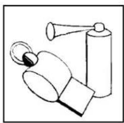
According to both Inland and International Rules, all boats must carry a way of producing an efficient sound signal. If your vessel is 12 meters (39' 4") or longer, a power whistle or power horn and bell must be carried. Bell mouth must be at least 7 7/8"
diameter.
The sound signal made in all cases must be capable of a four or six second blast audible for one half mile. See the section discussing bridge and whistle signals for more information.
RADIO COMMUNICATIONS
VHF radios are used for distress and ship to shore and ship to ship communications today. Learn the specialized messages such as Mayday, Mayday, Mayday. It is only used when life or vessel is in imminent danger.
Many of the more recent VHF's feature DSC capability which offers the ability to place and receive digital calls directly with vessels and shore stations including USA and Canadian Coast Guards. Channel 70 is reserved exclusively for DSC calls. Refer to the VHF owner's information since you need to establish a Mobile Maritime Safety Identity (MMSI) number before using the DSC feature. A MMSI number identifies each DSC radio, like a telephone number. The FCC requires a ship station license for all vessels equipped with a marine VHF radio.
NAVIGATION LIGHTS
The U. S. Coast Guard requires recreational boats operating at night to display navigation lights between sunset and sunrise along with other periods of reduced visibility. Navigation lights help avoid collisions by improving the night visibility of vessels. Red and green directional lights, white stern lights, white masthead lights and white all-around lights must be displayed in specified positions, depending on boat size, and mode of operation.
The configuration of visible lights tells an operator the size, direction of travel and means of propulsion (sail, power, rowing or at anchor) of another vessel. This helps both operators determine who has the right of way. Larger boats are required to carry bigger, brighter lights that are visible over longer distances. See the light requirement chart for pleasure craft.
MARINE SANITATION DEVICES
Recreational vessels under 65' with installed toilet facilities must have an operable marine sanitation device (MSD) on board. Vessels 65' and under may use Type I, II, or III MSD's. All installed MSD's must be U.S. Coast Guard certifi ed. The MSD's are labeled to show conformity to the regulations.
NAVIGATION RULES
The navigation rules establish actions to be taken by vessels to avoid collision. They are divided into Inland/International. Operators of vessels 39.4' or more shall have on board and maintain a copy of the Inland navigation rules.
NAVIGATION LIGHT RULES


| figure 7 a b c Figure 7 | Sailboat using sail alone, less than 7 meters in length: If impractical to display lights in figure 4,5 or 6, a single white light may be displayed in time to prevent a collision (figure 7c). Row Boats or Paddle Boats One all-round white light ready to display in time to prevent a collision (figure 7 a or b). | Great Lakes figure 7d Motorboat or sailboat using power on Great Lakes: The lighting arrangements in figure 7d may be used instead of the arrangements in figures 1 and 2. |
| Location of lights on vessel | Visible Range | Degrees of arc lights | |
| Less than 12 m. | 12 m. but less than 20 m. | ||
| in miles | |||
| Masthead | 2 | 3 | 225° |
| All-round | 2 | 2 | 360° |
| Side lights | 1 | 2 | 112.5° each color |
| Stern light | 2 | 2 | 135° |
Boats less than 12 meters in length
Motorboats or sailboats using power: The lighting arrangements to figure 1, 2 or 3 may be used.
Sailboat using sails alone: The lighting arrangements in figure 4, 5 or 6 may be used.
Boats 12 meters but less than 20 meters in length
Motorboats or sailboats using power: The lighting arrangements to figure 1 or 2 may be used.
Sailboat using sails alone: The lighting arrangements in figure 4, 5 or 6 may be used.
Location of lights
Lights should be located as shown in the drawings.
The masthead light (forward white light in figures 1, 2 and 7d) must be at least one meter higher than the colored lights on a boat less than 12 meters in length and at least 2.5 meters above the gunwale on a boat 12 meters but less than 20 meters in length.
Exceptions
Motorboat or sailboat using power, built before December 24, 1980: The lighting arrangement in figure 1, 2 or 3 may be used. However, the arrangement in figure 3 is not acceptable on a boat that is 12 meters or longer on international waters.
POLLUTION REGULATIONS
NOTICE
DISCHARGE OF OIL PROHIBITED
THE FEDERAL WATER POLLUTION CONTROL
ACT PROHIBITS THE DISCHARGE
OF OIL OR OILY WASTE
INTO OR UPON THE NAVIGABLE WATERS
AND CONTIGUOUS ZONE
OF THE UNITED STATES IF SUCH DISCHARGE
CAUSES A FILM OR SHEEN UPON,
OR DISCOLORATION OF THE SURFACE
OF THE WATER, OR CAUSES A SLUDGE
OR EMULSION BENEATH THE SURFACE
OF THE WATER.
VIOLATORS ARE SUBJECT TO
A PENALTY OF \$5,000
MARPOL TREATY
The USCG now enforces the International Convention for the Prevention of Pollution from ships, referred to commonly as the MARPOL TREATY (marine pollution).
This international treaty prohibits the overboard dumping of all oil, garbage, ship-generated plastic and chemicals.
There is a placard on board your boat (typical example shown below) that explains the garbage and plastic dumping laws in detail.
Immediately notify the USCG if your vessel discharges oil or hazardous substances in the water. Call toll free 1-800-424-8802. Report the following information: location, source, size, color, substances and time observed.
No vessel may intentionally drain oil or oily waste from any source into the bilge of any vessel. A bucket or bailer is suitable as a portable means of discharging oily waste.
The placard noted above is normally located in the engine or may be attached to the engine hatch.
GARBAGE DISCHARGE
The act to prevent pollution from ships places limitations on the discharge of garbage from vessels. It is illegal to dump plastic trash anywhere in the ocean or navigable waters of the United States. Also, it is illegal to discharge garbage in the navigable waters of the United States, including the Great Lakes. The discharge of other types of garbage is allowed outside certain specified distances from shore as determined by the nature of that garbage. United States vessels of 26 feet or longer must display in a prominent location, a durable placard at least 4" x 9" notifying crew and passengers of discharge restrictions. USA vessels of 26' or longer equipped with a galley and berthing must have a written Management Plan describing the plan for collecting, processing, storing and discharging garbage, and designate the person charged with carrying out the plan.
The placard noted below is usually found under the galley or the cockpit refreshment center.
| THE DISCHARGE OF PLASTIC OR GARBAGE WITH PLASTIC INTO ANY WATERS IS PROHIBITED. THE DISCHARGE OF ALL GARBAGE IS PROHIBITED IN THE NAVIGABLE WATERS OF THE UNITED STATES AND IN ALL OTHER WATERS. WITHIN THREE NAUTICAL MILES OF THE NEAREST LAND. | ||
| THE DISCHARGE OF DUNNAGE, LINING, AND PACKING MATERIALS THAT FLOAT IS PROHIBITED WITHIN 25 NAUTICAL MILES FROM THE NEAREST LAND. | OTHER UNGROUND GARBAGE MAY BE DISCHARGED BEYOND 12 NAUTICAL MILES FROM THE NEAREST LAND. | OTHER GARBAGE GROUND TO LESS THAN ONE INCH MAY BE DISCHARGED BEYOND THREE NAUTICAL MILES FROM THE NEAREST LAND. |
| A PERSON WHO VIOLATES THE ABOVE REQUIREMENTS IS LIABLE FOR A CIVIL PENALTY OF UP TO 25,000, A FINE OF UP TO50,000, AND IMPRISONMENT FOR UP TO FIVE YEARS FOR EACH VIOLATION, REGIONAL, STATE, AND LOCAL RESTRICTIONS ON GARBAGE DISCHARGES MAY ALSO APPLY. | ||
LIFE RAFTS
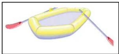
Inflatable life rafts are recommended for ocean going and vessels operating in a large body of water like the Great Lakes. They provide a shelter for extended periods. If used, make sure it is large enough for all aboard and contains the proper emergency equipment pack. Also, periodically have the unit professionally serviced. Make sure the life raft is Coast Guard approved since it would require meeting a number of stringent material and performance standards.
USCG MINIMUM EQUIPMENT REQUIREMENTS
Use the chart below as a guideline for assuring your vessel is outfitted to meet USCG standards. Remember to check with local and state authorities for additional equipment requirements. Make sure your vessel certifi cate of numbers are on the boat, updated and displayed properly according to state requirements. Keep the paperwork on board in a watertight and safe environment. Make sure it is quickly accessible.
On documented vessels keep both the original and current certifi cate on board stored in a safe, dry, and accessible location. Also, on documented vessels make sure the vessel name/hailing port are marked on the hull exterior with letters not less than 4" in height. In addition, the Offi cial Number must be permanently affi xed on a clearly visible interior structure part of the boat-block type Arabic numbers not less than 3" in height.
USCG Minimum Equipment Requirements for Recreational Vessels
| Boat Size in Feet | 16' | 26' | 40' | 65' | 165' |
| Personal Flotation Devices1 | One Type I, II, III, or V per person | One Type I, II, III, or V per person plus one Type IV throwable | |||
| Fire Extinguishers2 | One B-I, any type | One B-II or Two B-I | One B-II and one B-I, or three B-I | One or more B-II (vessels 0-50 tons gross)Two or more B-II (vessels 50-100 tons gross) | |
| No Fixed System | |||||
| With Fixed System | No Portables Required | One B-I | Two B-I or one Class B-II | ||
| Visual Distress | Night signals required | Minimum of three day-use and three night-use (or three day/night combination) pyrotechnic devices5 | |||
| Signals | when operating at night | ||||
| Sound Producing | Horn or whistle recommended to signal intentions or signal position | One bell, and one whistle or horn required to signal intentions or position | |||
| Devices | |||||
| Backfire Flame | One CG-approved device on each carburetor of all gasoline-powered engines built after April 1940, except outboard motors | ||||
| Arrestor | |||||
| Ventilation | CG standard system required on gasoline powered vessels with enclosed engine compartments built after August 1980 | ||||
| Navigation Lights | Sidelights, Stern Light and Masthead6,7 | ||||
| Under Power3,4 | |||||
| Under Sail | Sidelights and Stern Light6,8 | ||||
| Rowing | Same as "Under Sail" | ||||
| At Anchor | All-round light, 2nm (at night) or black anchoring ball (during the day) when outside a designated anchorage | ||||
| Visibility Range | 1nm Sidelights, 2nm all others | 3nm Masthead, 2nm all others | 5nm Masthead, 2nm all others | ||
| Pollution | "Honor system" (no plaques required) | 5" x 8" Oil Discharge placard and 4" x 9" Waste Discharge placardVessels over 40' with a galley must have a Waste Management Plan | |||
| Regulations | |||||
| Marine Sanitation | Vessels with installed toilet facilities must have an operable, | Type II or III MSD only | |||
| Devices | CG-certified Type I, II or III Marine Sanitation Device (MSD). Subject to local laws! | ||||
| Navigation Rules | Familiarity with the Inland Navigation Rules required | The Inland Navigation Rules ("Rules of the Road") must be kept on board | |||
| 1. Pfd's must be CG approved, wearable by the intended user and readily accessible.2. Fire extinguishers required on boats with enclosed engine compartments (not outboards), enclosed living spaces or permanent fuel tanks.3. Sailboats operating under engine power are considered power driven and must follow the "Under Power" rules. During the day, motorsailing vessels are required to fly a motoring cone.4. Power-driven vessels under 23' and under 7 knots can substitute a white lantern or torch in place of the required lights.Additions to theses requirements are prescribed by some individual state laws. Check your state's Boating Safety Handbook for a complete list. | 5. Non-pyrotechnic substitutes: 1 orange distress flag (day-use) and 1 electric SOS signal light (night-use).6. All boats under 65' can substitute a single bi-color light for sidelights.7. Boats under power under 40' can substitute a single all-round light for separate stern and masthead lights.8. Boats under sail under 40' can substitute a tri-color light for separate sidelights and stern light. | ||||
EXHAUST & CARBON MONOXIDE
Carbon monoxide (CO) in exhaust can be hazardous. especially from gasoline engines, gasoline generators, grills, stoves, space heaters and on a much smaller degree diesel engines.
CO is a natural by-product of the gasoline engine using an artificial spark. Diesels on the other hand detonate fuel using pressure and temperature. Looking at the two engine another way, gasoline engines use much more oxygen up in the combustion process which contributes to a much higher CO build-up. Although diesels do produce a small amount of CO the combustion process operates with much greater amounts of oxygen which the end result is a much lower CO level.
Ensure that you read the information and follow all the recommendations regarding CO.
Familiarize your crew, passengers and yourself with the sources, symptoms and possible effects of carbon monoxide poisoning. Remember that boats in the same general vicinity can cause your vessel to accumulate dangerous CO levels in the cabin and or in the cockpit.
For safety sake avoid the following:
- Do not park by other boats with their engine idling or generator cycling for an extended period of time.
- Do not disable the carbon monoxide alarms that come with your Regal boat. Test the units in accordance with the alarm manufacturers instructions.
- Do not operate an engine for extended periods of time while in a confined area or where exhaust outlets face a sea wall or bulkhead.
- Do not operate the engine for an extended period of time with the canvas in the upright and installed position.
- Have the engine exhaust system inspected when the boat is in for service.
- Persons sleeping can easily be overcome by carbon monoxide without realizing it. Do not sleep on board while an engine or generator is running close-by.
- Do not operate your vessel for extended periods with the bow up in slow cruise conditions especially close behind a vessel being towed or one operating at slow speeds.
- When underway open all hatches, windshield vents, and main cabin entry door to allow proper airflow from bow to stern.
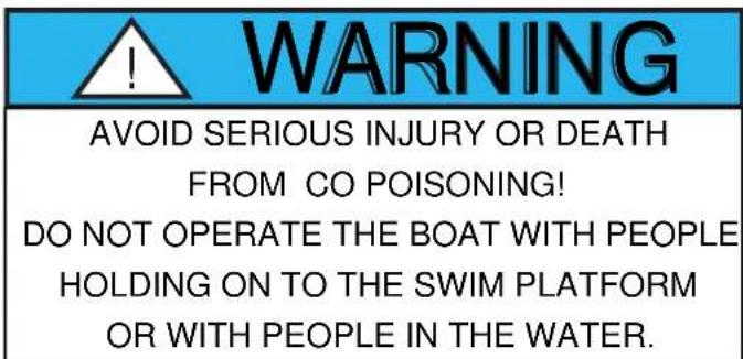

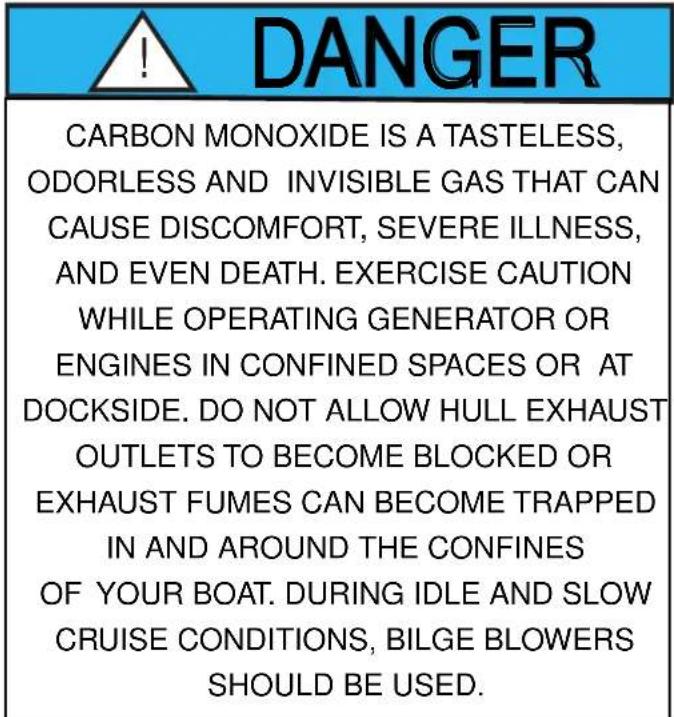
Blockage of exhaust outlets can cause carbon monoxide to accumulate in the cabin and cockpit area even when the hatches, windows, portholes and doors are open. Sea walls and other confined spaces can cause CO levels to be dangerously elevated.

Exhaust from another vessel alongside your boat, while docked or anchored, can emit poisonous CO gas inside the cabin and cockpit areas of your boat.
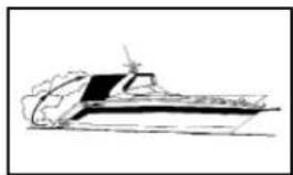
The “station wagon effect” or backdrafting can cause CO gas to accumulate inside the cabin, cockpit/hardtop or bridge areas when the boat is under-way, using protective weather coverings (canvas), high bow angle, improper or heavy loading, slow speeds, or at rest. This can occur when traveling behind another boat.
How does CO affect us?
In high concentrations, CO can be fatal in minutes. However, the effects of lower concentrations over a extended period of time can be just as lethal. Our blood uses hemoglobin to carry the oxygen we breath to different body parts. Unfortunately, hemoglobin carries CO more readily than it does oxygen. The result is when we breathe in CO it replaces oxygen in our blood and we begin to suffocate. Also, when we are removed from the CO source it remains in our blood for hours causing long term effects. People have been known to become sick and even lose consciousness hours after exposure.
Carbon monoxide accumulation requires immediate attention! Thoroughly ventilate cabin and cockpit areas. Determine the probable source of the carbon monoxide and correct the condition immediately. Anyone with symptoms of CO poisoning should be placed in a fresh air environment and medical attention found immediately. Regal has installed CO detectors on your boat. Have these detectors professionally calibrated at regular intervals according to the equipment manufacturer's recommendations.
A Few Notes About Diesel/CO Poisoning
The diesel engine under normal combustion produces much smaller amounts of CO. Therefore, it is far less likely to be fatal to a healthy person. Other factors including weather, temperature and engine condition can greatly affect the unsafe build-up of CO. The best approach is to respect and treat the engine, generator and other vessel components the same way you would a gasoline propulsion system giving particular attention to the sources and possible effects of CO poisoning!
Diesel exhaust in the combustion process produces various components and the captain must be aware that the build-up of these select components over a period of time can cause CO or seasickness like symptoms.
These include carbon dioxide, carbon monoxide (CO), Nitrogen dioxide, nitric oxide, sulfur dioxide and others.
A healthy person breathing in sulfur dioxide over a period of time through a diesel engine or generator exhaust can develop nausea. This condition is not life threatening but the person may exhibit CO poisoning or seasickness symptoms. Just never rule out that it could be CO poisoning! Immediately find the source of the problem and move the individual to a fresh air environment!
Symptoms of excessive exposure to carbon monoxide (CO) are:
• Dizziness
- Watering, itchy eyes
• Drowsiness
- Flushed appearance
• Nausca
- Inattentiveness
- Headache
- Incoherence
- Ringing in the cars
• Fatigue or vomiting
- Throbbing temples
- Convulsions

To help prevent carbon monoxide accumulation, ventilate your cabin and cockpit while underway. Open a forward hatch, porthole or window to allow air to travel through the boat's interior and
cockpit. See the illustration for desired airflow.
NOTE: Never occupy moored boat with engines running and/or canvas completely covering vessel.

INSPECT THE EXHAUST SYSTEM. IMMEDIATELY REPAIR OR REPLACE LEAK- ING, CRACKED AND CORRODED, OR MISSING EXHAUST COMPONENTS.
■ Before each trip inspect engine and generator.
■ Make sure all exhaust hose clamps are in place and secure.
■ Look for exhaust leaking from the exhaust system components, indicated by rust and or black streaking, water leaks, or corroded or cracked fittings.
■ Inspect all rubber exhaust hoses for burned or cracked areas. All rubber hoses should feel soft and and be free of kinks.
■ Visually verify that water exits at the engine exhaust outlet.
- Keep an ear tuned for any change in exhaust sound that could indicate an exhaust component malfunction.
DO NOT OPERATE THE VESSEL IF ANY OF THE ABOVE CONDITIONS EXIST. CONTACT A MARINE PROFESSIONAL!
NOTICE
CARBON MONOXIDE PRECAUTIONARY LABELS ARE LOCATED AT THE HELM, TRANSOM AND CABIN.
ENSURE THAT ALL ABOARD READ AND UNDERSTAND THE SIGNS AND EFFECTS OF CARBON MONOXIDE (CO).
CARBON MONOXIDE DETECTORS
At Least Annually
Your Regal boat features designated sleeping accomodationsTo be performed by a marine professional:
along with galley sink and head compartments. Working CO detectors must be utilized. They are standard equipment on your Regal boat. Mooring by boats running gasoline generators along with vessels using gas cooking/grilling/heating devices could lead to dangerous levels of carbon monoxide on your boat. Always be aware of other vessels mooring close to you especially if you are staying on board overnight. Read the owner's manual and vendor information regarding the CO detectors installed on your vessel.
Follow the periodical service recommendations per the vendor regarding recalibration of the carbon monoxide detector.
Never attempt to repair a CO detector yourself.
Get to know the signs of carbon monoxide poisoning.
Remember that carbon monoxide (CO) is known as the silent killer.
√ Replace exhaust hoses or mufflers if any evidence of cracking, charring or deterioration is found.
√ Replace the engine water pump impeller along with the plate and housing if necessary. This will help prevent cooling system and exhaust system overheating.
☑ Inspect each of the metallic exhaust components for cracking, rusting, leaking or looseness. Pay detailed attention to the exhaust manifold, cylinder head, water injection elbows.
BOATING & ALCOHOL
! WARNING
FEDERAL LAWS PROHIBIT OPERATING A VESSEL UNDER THE INFLUENCE OF ALCOHOL OR DRUGS. THESE LAWS ARE VIGOROUSLY ENFORCED BY ALL ENFORCEMENT AGENCIES.

Operating a vessel while intoxicated became a specific federal offense effective in 1988. The ruling set federal standards for determining when an individual is intoxicated. If the blood alcohol content (BAC) is .10% (.08 in some states) or higher for operators of recreational vessels being used only for pleasure are subject to a civil penalty up to \1,000 or criminal penalty up to \5,000, one year imprisonment or both. In some states the fi nes and imprisonment may increase signifi cantly.
The effects of alcohol and drugs account for the highest single cause of marine accidents and deaths. Most deaths in boating accidents occur when someone falls into the water. Balance is one of the first things you lose when drinking alcohol or under the influence of drugs. The problem arises out of not knowing your balance is restricted.
Overall vision is reduced by alcohol especially at night, along with double or blurred vision. Peripheral vision is lessened which restricts seeing vessels or objects on the side. Also, color awareness decreases especially with red and green which happen to be the colors of boa navigation lights, buoys, and channel markers.
Alcohol will greatly increase your heat loss so it increases the effects of hypothermia. Finally, your ability to make correct judgements in emergency situations is greatly reduced. Alcohol takes away the brains ability to process information quickly and delays a persons reaction time.
Don't drink and drive!
ALCOHOL MYTHS AND FACTS
Myth: Beer is less intoxicating than other alcoholic beverages.
Fact: One 12 oz. can of beer has about the same amount of alcohol as a 5oz. glass of wine or a shot of liquor.
Myth: Black coffee, fresh air, and a shower will sober the effects of alcohol.
Fact: After consuming alcohol time is the only thing that will sober you up. Our bodies average burning 1 oz. of alcohol every hour. If a person is drunk, it will take a person seven or more hours to sober up.
Myth: Telling if a person is too drunk to operate a vessel is easy.
Fact: Many experienced drinkers have learned to compensate for the visual effects of alcohol and can disguise their drunk condition.
Myth: You can judge if you are fi t to operate a boat. Fact: Judgement is one of the first elements you lose when drinking.
BOATING ACCIDENTS

The following is a list of common causes of boating accidents. Be aware of them and take the necessary steps to ensure that yourself and crew are educated and prepared to act in an emergency.
-
Mixing boating and alcohol. Remember, the skipper is responsible for his crew, passengers and vessel.
-
Trying to reach the bow by the deck walk-around at unsafe speeds. Use the center walk-through.
-
Someone sitting on the bow, deck, or swim platform while underway.
-
Choosing a boating outing day with inclement weather, especially in high winds and thunderstorms in the forecast or staying out when bad weather is approaching.
-
Disembarking without checking all the fluids or systems; and especially fuel system components.
-
Not monitoring the boating traffic or possible obstructions around you.
-
Emergency communications equipment, signaling devices, and navigation lights not working.
-
Improper boat handling especially high speed turns in rough water. Using trim improperly.
-
Being too far from shore with inadequate fuel supply or navigational aids.
-
Passengers, especially children that are not wearing the proper life saving devices.
-
Skipper or passengers not seated in the boat.
REPORTING BOATING ACCIDENTS

According to the Federal Boat Safety Act of 1971 involving collision, accident or other casualty, the operator must make a formal report within 48 hours to the nearest state
boating authority when the incident involves:
-
Death
-
Injury requiring treatment other than first aid
-
The disappearance of someone from a boat under death or injury circumstances.
A formal report must be made within 10 days for accidents involving more than \$2000 damage or complete loss of vessel.
For information regarding accident reporting, plaease call the Boating
Safety Hotline at 800-368-5647.
If there is no state provision for reporting boating accidents a report must be made to the Coast Guard offi cier in charge, Marine Inspection Unit nearest to the accident site or USCG station.
RENDERING ASSISTANCE
The operator of a vessel is obligated by law to provide assistance that can be provided safely to any individuals in a dangerous situation on the waterway. The operator is subject to fine and or imprisonment for failure to do so.
! DANGER
AVOID BODILY INJURY OR DEATH FROM FALLING OVERBOARD! ALL OCCUPANTS SHALL STAY SEATED IN THE COCKPIT WHILE THE BOAT IS RUNNING.
FEDERAL REGULATIONS RE- GARDING VESSEL SECURITY
Federal maritime regulations contain specific information when operating near naval vessels, oil tankers and cruise ships.
- You may not approach within 100 yards of any U.S. naval vessel, oil tanker, or cruise ship. When this is impossible to avoid, you must contact either the vessel or the Coast Guard escort vessel on channel 16 of the VHF radio.
- Also, you must operate at minimum speed within 500 yards of these vessels.
! WARNING
Do not approach within 100 yards of any U.S. naval vessel. If you need to pass within 100 yards of a U.S. naval vessel in order to ensure a safe passage in accordance with the Navigation Rules, you must contact the U.S. naval vessel or the Coast Guard escort vessel on VHF-FM channel 16.

You must operate at minimum speed within 500 yards of any U.S. naval vessel and proceed as directed by the Commanding Officer or the official patrol
Violations of the Naval Vessel Protection Zone are a felony offense, punishable by up to 6 years in prison and/or up to \$250,000 in fines
WATER SPORTS
Besides learning the safety precautions for safe boating, as well as understanding and knowing required rules and regulations, you are obligated to be particularly careful around other water sportsman, such as scuba divers, water skiers, wake boarders, and fi sherman.

WARNING
AVOID SERIOUS INJURY OR DEATH! DO NOT OPERATE THE BOAT WITH PEOPLE IN THE WATER ON TOP OR HOLDING ON TO THE SWIM PLATFORM STRUCTURE.
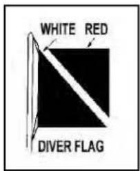
Whenever you see a "Diver Down" flag, maintain a distance of at least 100 feet on inland waters. In bays and open waters stay 300 feet away. The flag indicates a diver in the water. If a diver is operating from your boat, be certain to use this flag and post a lookout on board to observe the diver's air bubbles.
SWIM PLATFORM
On integrated or extended swim platforms you should make periodic inspections of the swim ladder and hardware
that supports the platform to ensure that all connections and fittings are tight and in good condition.
Use heed when operating the boat in reverse to insure that water does not accumulate excessively on the platform or transom, especially in rough seas or strong currents.
Do not exceed the platform recommended maximum capacity label! Typical label shown.
Read and understand the warning label above regarding "teak surfi ng."
FISHING

Most boaters fi sh from time to time. With the propulsion systems of today it is possible to fi sh in out-of-the-way places. When crusing, stay clear of fi sherman. They may have lines or nets out which might be cut or get caught in your propeller if you come too close. Slow down when approaching fi shing boats. Do not return to cruising speed until the boats have been passed. If a fi shing boat should be anchored, a large wake could fl ip or swamp the boat, upset fi shing gear, pull the anchor loose from the bottom or worse yet cause someone to fall overboard.
When fi shing from your boat, never anchor in a shipping channel or tie up to any navigational aid. These must be kept clear of at all times.
Be sure to carry a local chart of the area to back up your plotter and be on the lookout for shallow water and hidden obstructions. Many times local conditions change and there is a time lag on the plotter chip until the next revision.
Pick up a tidal chart if appropriate so you do not end up grounded.
WARNING! MAXIMUM CAPACITY OF SWIM PLATFORM 500 POUNDS 226 KG
WEATHER/WATER CONDITIONS WAVES & FOG
Before a boating outing check the weather conditions. As we all know the weather can change rapidly in many parts of the country. It does so sometimes without being predicted. NOAA weather radio reports are continuously available on designated frequencies installed on VHF radios and various handhelds. Also, many local radio stations carry weather reports along with on-line information.
CLOUD FORMATIONS
Clouds indicate the type of current weather and upcoming changes in the weather. Knowing the type of cloud formation can assist you in understanding current weather. Flat clouds (stratus) normally indicate stable air. Cumulus clouds indicate unstable air. Many times a “cottonball” or cumulus cloud builds vertical height in the afternoon and the result is a thunderstorm with increased winds and waves; sometimes these storms are quite violent. Also, watch spouts with high vortex winds can develop over water. You can find additional weather information (meteorology) at your local library or on the internet.
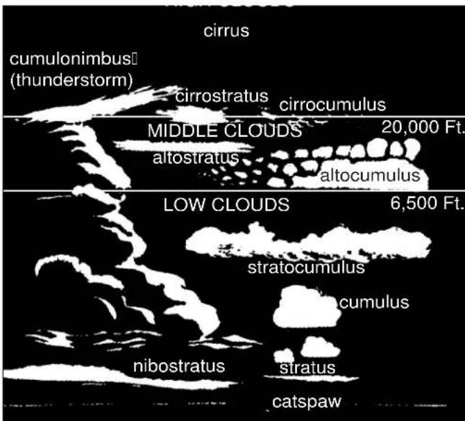

As the wind blows across water waves are created. The stronger the wind and increased distance across the water enlarges the wave action.
Other factors that can cause problem situations for vessels are fog, currents, and tidal changes.
Fog can develop inland on clear, calm mornings. Coastal areas see large
“blankets” of fog roll in and stay for extended time periods sometimes causing hazardous navigation conditions. If you are caught in the fog, do not panic. Think of the best plan of action and proceed carefully. If you are limited in navigation equipment at the first sign of fog proceed to the nearest shoreline and wait until the fog lifts.
Boats equipped with navigation equipment, local waterway experience and charts should proceed to a safe harbor. Use extreme caution, signal as needed, and reduce to a speed where you can stop within half of your forward vision range.
If foul weather catches you at sea do the following:
- Slow down. Proceed with caution and put on your life vests.
- Try to reach the nearest safe shoreline.
- Navigate your vessel slowly into the waves at a 45 degree angle.
- Passengers should sit low in the center of the vessel.
- Monitor your bilge pump. Make sure sump stays free of water.
- Secure loose gear. Make ready emergency equipment.
- If the engine stops, throw the anchor over the bow. If needed use a sea anchor. Never anchor off the stern.
Rules Of The Road
NAVIGATION RULES DEFINED

The Navigation Rules set forth actions to be followed by boats to avoid collision. They are referred to as the "Rules of the Road". There are two main parts referred to as the You can order the Inland & International Navigation Rules from:
Superintendent of Documents
U. S. Government Printing Office
Washington, DC 20402
Tel: (202-512-1800) Fax:(202-512-2250
NAVIGATION RULES
RIGHT OF WAY
inland and international rules. The inland rules apply to vessels operating inside the boundaries of the United States.
The international rules (referred to as 72 COLREGS) apply1. Cross waves at right angles.
to vessels operating on the high seas and all connected waters outside the established demarcation boundaries. Most navigational charts show the demarcation lines by red dotted lines and are published in the navigation rules. Remember to consult state and local agencies since areas such as “no wake zones,” swimming beaches, “diver down flag” and inland landlocked lakes fall under their jurisdiction. This section is only an introduction to the “rules of the road”. We strongly recommend additional training before getting behind the “wheel” of your boat.
-
When caught in heavy water or squalls, head either directly into the waves or at a slight angle. Reduce speed, but maintain enough power to maneuver your boat safely.
-
Keep your speed under control. Respect the rights of other boaters engaged in all water sports. Give them plenty of operating room.
-
Whenever meeting a boat head on, keep to the right where possible.
-
When two boats cross, the boat to the right (starboard) has the right of way.
! WARNING
TO AVOID INJURY AND DEATH FOLLOW THE NAVIGATION "RULES OF THE ROAD" TO PREVENT COLLISIONS.
- When overtaking or passing, the boat being passed has the right of way.
In general, boats with less maneuverability have right-of-way over more agile craft. The skipper must keep his craft clear of the following vessels:
- A vessel not under command or aground; due to their circumstances, these vessels have no maneuverability.
- A vessel restricted in its maneuverability; these vessels usually are performing work which limits their maneuverability. Examples are boats surveying, dredging, laying pipe or cable, or servicing navigational markers.
- A vessel engaged in fi shing; these include boats fi shing with lines, trawls or nets, but not trolling lines.
- Sailboats; they have the right-of-way over powerboats. However, if a sailboat is using a prop to move forward, it is considered a powerboat even if the sails are up.
- Remember the unwritten “rule of tonnage”. Basically a smaller tonnage vessel should take every effort to avoid close quarters with a larger tonnage vessel. One way to accomplish this is to have a designated human lookout to “eyeball” the horizon for any developing collision course.
- Use defensive driving skills on the waterway just as you do on the roadway. The other vessel may not know the "rules of the road". Be alert and ready to take immediate action.
- If a collision course is unavoidable neither boat has the right of way. Both boats must react to avoid an accident according to the rules of the road.
LOOKOUTS
International and Inland navigation rules spellout the specifics of establishing a lookout. A lookout is legally defined by the court system as a person who has specifically charged duties on board such as observing sounds, echoes, lights and any inhibitors to navigation with complete throughness as permitted by the circumstances.
The term “specifi cally charged” means that the lookout has no other duties at that time that could prevent him from keeping a proper watch.
Of course the skipper must delagate the lookout duties to a seasoned crew member who can react to events quickly and communicate effectively with the captain with little notice.
As captain of your yacht you are responsible for the vessel and the crew. Choose an experienced individual as lookout and review the navigation rules with this person so he can make the right call quickly as situations develop.
WHISTLE SIGNALS
ONE LONG BLAST: Warning signal
(Coming out of slip)
ONE SHORT BLAST: Pass on my port side
TWO SHORT BLASTS: Pass on my starboard side
THREE SHORT BLASTS: Engine(s) in reverse
FOUR OR MORE BLASTS: Danger signal
BRIDGE SIGNALS

NAVIGATION RULES
The Navigation Rules set forth 3 types of crossing situations- crossing, meeting, and overtaking. In each case, both boats are governed by special procedures.
In a head-on meeting, both vessels must sound a single blast to give way toward starboard and pass to port.
These rules appear when there is a risk of collision. In a crossing situation be aware of the other craft's position. For safety, there should be a noticeable change in the angle, bow or stern; a gradual change in position indicates possible danger.
![graph TD A["Top Row: Boat"] --> B["Top Row: Ship"] B --> C["Top Row: Boat"] C --> D["Top Row: Ship"] D --> E["Top Row: Boat"] E --> F["Top Row: Ship"] F --> G["Top Row: Boat"]](/content/2026/05/1030542/images/594c6e355a4131a59369bf8df3303e5b44ca50fb94ece3e113c905fe2d313582.jpg)
![graph TD A["Top Ship"] --> B["Left Arrow"] A --> C["Right Arrow"] A --> D["Bottom Ship"] style A fill:#f9f,stroke:#333 style B fill:#ccf,stroke:#333 style C fill:#cfc,stroke:#333 style D fill:#fcc,stroke:#333](/content/2026/05/1030542/images/7e01b5a10bbb934c98df1c66264a609a91656a11f81b6f5518a1287585aeee95.jpg)
![graph TD A["Top: Boat Section"] --> B["Bottom: Boat Section"] B --> C["Top: Boat Section"] C --> D["Bottom: Boat Section"] D --> E["Bottom: Boat Section"]](/content/2026/05/1030542/images/76c0953ae2bd396ae313995481c3366e3bca1558b6ff5a99b4767f43a46207b6.jpg)
NAVIGATION RULES
An overtaking boat is burdened, and is not the priveleged craft, even though it approaches the danger zone of the overtaken boat.
The overtaking boat first signals with a single blast if that boat desires to pass on the starboard side of the boat ahead, or a double blast if passing to port. The overtaken craft responds with the same signal if safe, or with the danger signal (5 short blasts or more) if unsafe. The boat overtaking must not pass unless the appropriate signals are sounded.
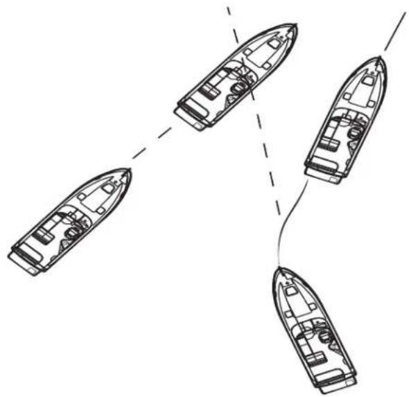
![graph TD A["Initial State"] --> B["Arrow to Next State"] B --> C["Final State"] style A fill:#f9f,stroke:#333 style B fill:#bbf,stroke:#333 style C fill:#f9f,stroke:#333](/content/2026/05/1030542/images/73b2fbf816278e7d866c55fd56157101622b60c871070a1519c836fba0d57f0d.jpg)
NAVIGATION AIDS
Navigation aids are placed along coasts and navigable waters as a guide for mariners in determining their position in reference to land and hidden danger. Each aid provides specific information. They form a continuous system of charted markers for monitoring on the plotter or providing accurate piloting on paper as a backup.
Your on board plotter provides up to date navigation aids. Besides coastal maps a complete domestic interior waterway grid is featured on the plotter.
If desired, there are hand-held GPS devices that are available as back-up devices. In addition, nautical charts are provided by the National Ocean Service (NOS) and are distributed nationwide through marinas and outlet stores.
These charts show the geography of the coast, water depth, landmarks, navigation aids (buoys and markers), marine hazards, and port facilities. Use only up-to-date charts for navigation. We recommend when purchasing a chart to look for the weather resistant ones.
Buoys provide a roadmap to keep the skipper on course and to avoid hazards. Buoys are identified by light, shape, color and in severe weather conditions by sound.
Buoys or beacons called lateral markers indicate the port and starboard sides of the waterway to be followed. U. S markers follow the buoyage system known as Red Right Returning. When returning from sea or traveling upstream, the green markers are to port (on your left) and the red markers are to the starboard side (on your right). When traveling downstream or out to sea the marker color would be reversed.
Before operating your vessel, learn to identify the various navigational aids such as lateral aids, mid-channel markers, information and regulatory markers.
NOTICE
SKIPPERS MUST NOT RELY ON BUOYS
ALONE TO MARK THEIR POSITION.
SEVERE WEATHER CONDITIONS
AND WAVE ACTION CAN ALTER
A BUOYS POSITION.
NEVER TIE UP TO A BUOY.
REGULATORY MARKERS
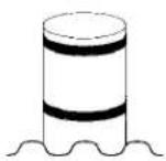

Diamond Shape
Warns Of Danger

Diamond Shape With Cross-Boats Keep Out

Circle Marks Area Controlled As Indicated

For showing information such as locations, distances and directions
NIGHT RUNNING
Boats operating between sunset and sunrise (hours vary by state), or in conditions of reduced visibility, must use navigation lights. Night time operation, especially during bad weather and fog, can be dangerous. All Rules of the Road apply at night, but it is best to slow down and stay clear of all boats regardless of who has the right-of-way. To see more easily at night, avoid bright lights when possible. Also, it is helpful to have a passenger (appoint as lookout) keep watch for other boats, water hazards and navigational aids.
To determine the size, speed and direction of other vessel at night, you should use the running lights. A green light indicates starboard side, and a red light indicates port side. Generally, if you see a green light, you have the right-of-way. If you see a red light, give way to the other vessel.

BRIDGE CLEARANCE
Be aware that your vessel requires a specified bridge clearance height. This height is a measured estimate from the waterline to the top of the highest equipment height. The estimated height can change because of variances in the loaded condition of the vessel and equipment variances. Consult the bridge clearance specifications located in Chapter 12 (Technical Information section).
Some bridges are tendered. Know and use the proper bridge signals when approaching these bridges (see bridge signals in this chapter). You can also monitor and communicate on channel 13 of a VHF radio for bridge information in most domestic locals. Other bridges are marked with a clearance measurement and you are on your own. It is recommended that you have a look out posted for additional visual assistance when entering a bridge zone.
After determining your vessel will clear the bridge proceed with caution at a safe idle speed. Keep your eye on vessel traffic at all times in order to react quickly. Keep both hands on the helm since you may need to change course because of current and wind conditions. Resume a safe speed once clear of the bridge structure and acknowledgment of clear visibility.
Just use common sense around any type of bridge structure!
BRIDGE LIGHTING
Bridge lighting is maintained by the Department of Homeland Security. On the following pages are 2 typical examples of night-time bridge lighting. As the skipper approaches bascule and fixed bridges light position (arc of visibility) and color will indicate the safe channel through the bridge. Notice green denotes the “safe” entry location on single-span bridges and green or white on multiple-span bridges designates the main channel. In addition, green denotes the “up” position for single and double lift bridges.
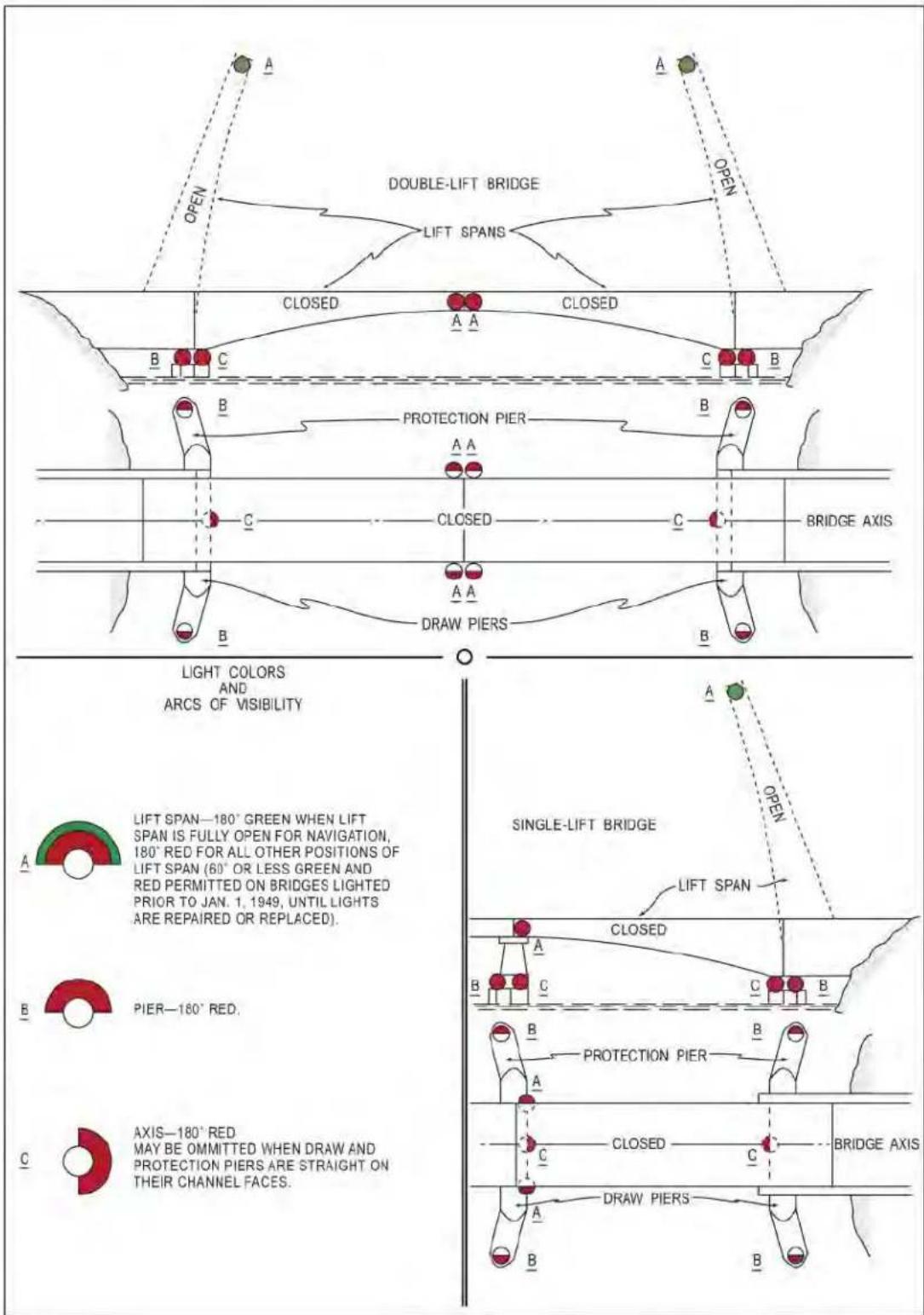

Systems
OVERVIEW

In this chapter Regal on board systems are introduced. Information includes several main systems including fuel, electrical, air conditioning

(AC), windlass, water, waste, electronics, entertainment and trim tabs.
This is the “meat and potato” section for equipment operation.
A system description, location of components, operational information along with common problems and solutions are covered with each of the system components. Enhanced vendor component details can be found in the owner's information packet.
Be sure to read and follow any danger, warning, or caution labels in reference to boat systems or individual equipment components.
Your Regal boat may not contain all of the equipment or systems shown. Regal has the right to modify, update or delete equipment and/or systems at anytime.
Refer to the vendor documentation located in the owner's information packet for more detailed information of individual system components.
TYPICAL GASOLINE FUEL SYSTEM
In this section, a typical EPA approved domestic gasoline fuel system with components is introduced. The fuel system includes the fuel tank, fuel feed lines, fi ll and vent fi ttings along with fuel fi lters, emission devices natural ar powered ventilation systems.
Gasoline today is processed in a different manner than it was a few years ago. As a result it has become more unstable and the product shelf life has been shortened. As part of the Volvo product features the gasoline engine EVC system and transmissions are all protected by a fault handling system should a malfunction develop. A portion of this fault system is used to monitor the gasoline fuel system. Mercruiser propulsion systems offer “Smartcraft” technology which delivers key engine functions.
Select codes warn the captain with a “buzzer” sound while others will display on the helm tachometer, display, or alarm panel. The “pop-up” will alternate between the cause of the fault and a task to perform to aid in eliminating the situation.
It is important to read and understand your Volvo or MecCruiser propulsion owner's manual in order to react to a fault code should a malfunction display on the instrumentation or an alarm sound.
GASOLINE SPECIFICATIONS
Gasoline Requirements- Use nonleaded gasoline with the following minimum octane rating:
Inside United States-(R+M)2 (AK)- 87
• Outside United States- (RON) -90
The use of leaded fuels will damage the catalysts and can not be used with catalytic converters.
Gasoline in the United States and other areas is blended with 10% ethanol and is known as E-10 at the pumps. Marine engines used in your Regal boat may be operated with gasoline blended with no more than 10% ethanol and that meets the minimum octane specification.
Do not use ethanol blends greater than 10% such as a newer blend for select motor vehicles called E-15. Your marine engine may be damaged by more than 10% ethanol. A loss of performance may occur and the engine will not be covered by the engine manufacturer's warranty.

FUEL FEED FUEL
HOSE SENDER
(1 PER ENGINE)
FUEL FILL HOSE GENERATORFENT HOSE
FUEL TANK
Boats manufactured for domestic use are now required to be outfitted with an EPA compliant fuel system using an aluminum tank. This system uses parts such as special valving located inside the fuel tank. Also, there is a carbon canister which functions much like the one in an automobile. This component is located between the fuel tank and hull side vent. The carbon canister never needs to be replaced and is not a servicable item.
Tanks are initially outfitted to work with gasoline and diesel systems.
These tanks are tested and inspected along with the complete fuel system several times for safety requirements and quality by the fuel tank supplier, in house personnel and independent inspections by National Marine Manufacturers Association personnel.
FUEL FILL FITTING
The fuel fill tting is labeled "gas" and in addition displays the international symbol (See the next page). When fueling the boat keep the fill nozzle in contact with the fuel fill pipe since it decreases static electricity. Always use the recommended fuel octane rating as specified in your engine owner's manual.
Extinguish all fl ame producing agents before fueling!
FUEL VENT FITTING

COMBO FUEL FILL W/ INTERNAL VENT
Currently, domestic EPA compliant fuel tanks vent fumes back into the fuel tank system. While the tank is filled, air displaced by the incoming fuel is vented through the fuel system charcoal canister.
Your vessel uses a combo type (internal vented) fuel fi ll. Both the fuel fi ll and vent occupy the same cavity under a protective cover. If fuel overflows through the vent the design forces it back into the fuel fi ll hose and tank.
A seasoned skipper will hear a distinct sound as the tank nears the "top out" or full mode and may see fuel overfl owing back into the fuel hose through the vent. DO NOT OVERFILL THE TANK.
This helps avoid any overboard spills which harm the environment.
Note: On select vessels there is a key that fi ts into the fuel fi ll cap. Use it to secure the fi tting from leaking fuel. Stor the key in a safe place so it can be easily found for fueling. Check the vent fi ll screen periodically for debris.
ANTI-SIPHON VALVE

The gasoline fuel tank feed lines that run from the fuel tank to the engine fuel components each use an anti-siphon valve. The valve is threaded into each fuel tank fi tting at the feed line. The valve is pulled off its seat by fuel pump pressure as the engine is cranking or running. There is a ball and spring assembly inside the valve that is activated by fuel pump impulses. It allows a one-way fuel roadway to the engine fuel system. It prevents fuel from siphoning out of the tank in the event of a fuel line rupture or disconnected fuel feed hose. When the engine fuel components stop the fuel from cycling the spring forces the ball against the valve opening to stop fuel flow.
Note that vessels with generators will feature an anti-siphon valve at the generator fuel feed location.
Never remove an anti-siphon valve as it is a fuel system safety component. Also, never remove the ball and spring from the valve assembly. The anti-siphon valve requires no normal maintenance. Symptoms indicating possible valve problems may be fuel starvation at intermediate or high rpm or in extreme cases an engine that will not start. Contact your Regal dealer for further information.
FUEL GAUGE/SENDER

The dash fuel gauge is only an indication of the on board fuel supply. They are not exact reading instruments. Therefore, use the one third rule discussed earlier for monitoring your fuel supply. There are not many fi lling stations on the open waterways!
The gas sender located in the fuel tank uses a float system which sends a signal to the dash fuel gauge as to the estimated fuel tank level.
The new sending units feature a removable tube (B) which inserts inside the stainless steel sender (A) without having to remove the entire unit found in earlier units. The unit requires as little as 3" height to remove the tube. Also, a liquid-tite strain relief connector protects the harness.
A buna-N type fl oat travels the length of the sender tube (A) as the fuel level changes. The resistors inside the tubing read the fl oat level and send a signal to the dash gauge.
As an emergency tip in the event the fuel gauge shows no gauge activity or reads improperly:
Check the sender by disconnecting the 2 sender leads at the fuel tank and connecting an ohm meter between them. Make sure you zero out the meter by first connecting both red and black leads together and then adjusting the meter knob to zero. This needs to be performed to obtain a correct ohm reading. 'The actual resistance between the sender leads should be between 30 and 240 ohms.
FUEL FILTERS
Fuel filters are installed on your marine engines. They are of the spin on type similar to an automobile oil filter. Their main purpose is to trap dirt particles and condensation in the fuel system before it reaches the injectors. Impurities can clog up the injection system It is a good idea to keep an extra set of fuel filters on board along with a filiter wrench, catch container and clean rags for emergencies. Never use automotive style fuel filters on your vessel. Dispose of all fuel residue materials in an environmentally safe fashion.
CARBON CANISTER

The domestic EPA compliant fuel tank system contains a carbon canister. It is located at the starboard firewall bulkhead area in the engine room (bilge or sump). It's environmental mission is to catch and filter any contaminants that are attempting to exit the fuel system via the fuel tank vent hose. This component should last the life of the fuel system and requires no periodic maintenance other than checking the hose clamps for tightness.
GASOLINE VENTILATION SYSTEM
Gasoline propelled engines require a continuous supply of fresh air in order to generate peak horsepower and rpm. To deliver fresh air for the twin engines a dual set of permanently mounted vents are integrated into the boat's deck on both port and starboard sides. This is called the natural ventilation system.
When the engines are started fresh air is drawn through the vent system. As the demand for air increases in relationship to the engine revolutions per minute (rpm's) the engine induction system supplies the required additional air supply by inhaling more air.

As part of the gasoline combustion process fuel vapors can accumulate in the bilge and cause a possible explosion or fire. To offset the possibility of this happening a powered venti-
lation system exits fuel vapors and possible CO through a system of blowers with hoses that are stragedically placed in the lower third of the engine compartment. Gasoline vapors naturally seek the bilge bottom and the blowers evacuate any fuel vapors out the exhaust side of the ventilation system. This is known as the powered ventilation system. If you are working in the sump make sure you do not step on the black 4" blower hoses.
Check the vents periodically for any obstructions or foreign objects such as nests or spider webs. If the propulsion system is running at a lower than normal cruising rpm or seems to lack power or the vessel is slow to plane check the fresh air supply to the engines including the engine air filters.
Note that proper amounts of natural ventilation is even more important with diesel installations.
GASOLINE FUEL SYSTEM-GENERAL
WARNING
GASOLINE VAPORS CAN EXPLODE! BEFORE STARTING ENGINES OPERATE BLOWERS 4 MINUTES AND CHECK ENGINE COMPARTMENT FOR GASOLINE LEAKS AND VAPORS. RUN BLOWERS BELOW CRUSING SPEED.
! WARNING
AVOID SERIOUS INJURY OR DEATH FROM EXPLOSION OR FIRE RESULTING FROM LEAKING FUEL. INSPECT ENTIRE FUEL SYSTEM AT LEAST ONCE A YEAR.
NOTICE
SINCE GASOLINE IS AVAILABLE IN VARIOUS OCTANE LEVELS, REFER TO THE ENGINE MANUFACTURER'S OWNER'S MANUAL FOR THE CORRECT ONE FOR YOUR ENGINE. USING IMPROPER OCTANE FUEL CAN CAUSE ENGINE DAMAGE AND VOID THE WARRANTY.
WARNING
AVOID SERIOUS INJURY OR DEATH FROM EXPLOSION OR FIRE! NEVER STORE FUEL OR FLAMMABLE LIQUIDS ON BOARD.
! DANGER
AVOID PERSONAL INJURY OR DEATH! GASOLINE IS A HIGHLY FLAMMABLE AND EXPLOSIVE MATERIAL. PRACTICE "NO SMOKING" AND EXTINGUISH ALL FLAMMABLE MATERIALS WITHIN 75 FEET OF THE FUEL DOCK.
POSSIBLE GASOLINE FUEL PROBLEMS/SOLUTIONS

- Engines are hard to start or idle rough- This problem can be caused by foreign particles or water in the fuel system or a blockage in the fuel supply which causes a lean condition.
Check all fuel system lines, clamps, fi ttings and fi lters for tightness. Check the entire system for fuel leaks.
-
The engines hesitate at intermediate speeds or fail to obtain top rpm- Check the fuel system for possible leaks, clogged fuel filters and/or malfunctioning antisiphon valve.
-
The fuel tank reads low and the engines are running rough. The pick-up tube has possibly picked up some residual water from the bottom of the fuel tank. Pour dry gas into the fuel fill filling and fill the gas tank with fresh fuel. Test run the engines to purge impurities from the fuel system.
-
Fuel tank gauge not reading correctly/or not at all-If you disconnect the fuel tank sending wire leading to the dash gauge at the sending unit and ground it momentarily with the key on the dash guage should show full. Release the wire from the ground position and the gauge should show empty. Normally this would indicate the dash gauge is working properly. The next item to check would be the fuel sender ohms reading which is explained earlier in this section. Also, make sure the sender wires and ground are securely fastened and the ground wire is tight. Many times a loose ground wire will cause a malfunctioning dash gas gauge or the gauge needle moves irratically.
DIESEL FUEL SYSTEM- GENERAL
In this section, the basic diesel fuel system components are introduced. The fuel system includes the fuel tank, fuel supply and return lines, fi ll and vent fi ttings along with fuel fi lters and the ventilation system.
Diesel fuel today is processed in a different manner than it was a few years ago. As a result it has become more unstable and the product shelf life has been shortened.
A summary of so called diesel fuel “algae” along with its causes and effects will be outlined in this chapter.
As part of the product features the diesel engines, EVC system and the transmissions are all protected by a fault handling system should a malfunction develop. A portion of this fault system is used to monitor the diesel fuel system.
Select codes warn the captain with a “buzzer” sound while others will display on the helm tachometer, display, or alarm panel. The “pop-up” will alternate between the cause of the fault and a task to perform to aid in eliminating the situation.
It is important to read and understand your propulsion owner's manual in order to react to a fault code should a malfunction display on the instrumentation or an alarm sound.
DIESEL FUEL BASICS
Diesel fuel properties have changed in recent years due to the way the product is processed today at the refineries. A couple of decades ago diesel fuel, gasoline, home heating oil among other distillation products were processed by heating the crude oil. At different boiling temperatures, various parts of the crude oil were evaporated then condensed sending the final products to storage tanks for distribution. The distillation process generally produced stable diesel fuel with a storage life of several month
Around 50% of the oil left over from the distillation process was designated as heavy fuel oil being used for ship's, power plants, and industrial products such as nylon, plastics, and asphalt.
Refining crude oil today has changed dramatically due to increased demand for the product. A process called “chemical cracking” has allowed the refiner to extract more of the lighter distillates from the crude oil leaving about 16% of the residual as heavy fuel oils. Lowering the diesel fuel sulphur levels due to environmental concerns has led to further fuel instability. Due to these newer methods of refining diesel fuel is far less stable than the older distillation process.
There are different theorems on defi ning fuel system “algae” and how it develops in the vessel’s fuel tank. Algae is slang for the fungus that grows in fuel tanks.
One school of thought isolates two of the key fuel components. Asphaltenes and paraffins in this premise begin to oxidize and re-polymerize forming clusters resulting in fuel tank “algac”. As these clusters “grow” in size they cling themselves to tank walls and baffles.
Others state that “algae” is formed when water condenses in the boat’s fuel tank. Water can enter the vessel’s fuel tank through the fuel pumping process at the fuel dock since their tank may already be contaminated with algae-micro organisms. Once inside the tank these algae-microscopic organisms from the plant kingdom are able to combine with water and diesel to form tank sludge.
Keeping tanks free from water, dirt and micro organisms is almost impossible, but luckily you can eliminate them before they reach the engine and fuel injectors through the use of primary and secondary fuel filters. Algae ends up in the fuel system once the boat is running which breaks up the tank “algae” and/or sludge into mini clusters. 10
When this condition is present in the marine diesel fuel system the fuel does not combust rapidly as it should resulting in a loss of engine efficiency.
Basically, with either school of thought this “algae” or fuel tank sludge is the result of aging diesel fuel. It can occur in as little as 60-90 days depending on the condition of the tanks and environment where the diesel fuel is stored.
Using diesel fuel in this condition may cause the follow-
- Fuel tank sludge-remove manually or by chemicals
- Dirty engine oil
- Shortened engine component life
• Smoke emitting from the engine exhaust system
Carbon deposits in the engine
• Incomplete combustion - Loss of power and performance
• Clogged primary and secondary fuel filters - Malfunctioning fuel injectors
SOLUTIONS FOR RECOVERING DIESEL FUEL QUALITY
As a Regal boat owner you have a huge investment in your diesel propulsion system. Being the engines are a key component in the system, keeping the fuel system clean is a high priority.
Following are some solutions to help clean up a diesel fuel "algae" problem:
Periodically use a biocide to control microbial activity which can lead to more rapid formation or clustering of solids such as wax and asphalt. Remember that bio-
cides do not prevent microbes from forming but aid in breaking up the clusters. If the vessel is to be stored for over 2 months pour biocide in the semi empty vessel fuel tank or tanks. Fill the fuel tank with fresh diesel fuel to prevent condensation build up. Run the boat for a short run to better mix the biocide inside the fuel tank and fuel system before storing the vessel.
-
Always make sure the fuel tank fill cap is securely tightened to prevent any water infusion.
-
Always buy diesel fuel from a marina or fuel dock that moves a large amount of fuel through the pumps. Ask how often the fuel dock pump filters are changed and if their diesel fuel is blended with a biocide. Always carry a couple of extra primary and secondary diesel fuel filters. Use exact replacements in order to match micron filtering capacity.
-
Figure on changing both primary and secondary fuel system filters more often due to today's diesel fuel shorter storage life.
-
Make sure to drain the 10 micron Racor water separator fuel fi liter and the engine secondary fuel fi liter before each outing. Look for sludge/water. Dispose of contaminated diesel fuel properly in approved containers. Do not drain diesel fuel in the bilge.
-
Never let diesel fuel remain in the boat's fuel tank for more than six months. The cetane value will drop which is its ability to ignite easily. Good grades of diesel support a cetane rating around 50. When the cetane level drops the engine is more difficult to start. The combustion process moves from a controlled burn to an explosion. Pump out the old diesel and replace with a fresh supply.
Old diesel fuel creates more stress on engine parts and produces more noise than normal resulting in the trademark diesel clatter.
Pour a cetane booster and conditioner in the fuel tank with the new batch of diesel fuel.
Note: In severe cases of “algae” the fuel tank may need to be pumped out. To remove the ability to generate new algae, the tank should be pressure washed which removes small deposits of “algae” from the baffle system and hard to reach areas. Add a biocide (not a conditioner) and then top off the tank.
Remember: LESS AIR MEANS LESS WATER AND LESS GROWTH!
DIESEL VENTILATION SYSTEM
Diesel engines require a continuous supply of fresh air in order to generate peak horsepower and rpm. Because diesel fuel is far less likely to explode it does not require a blower system like gasoline powered vessels to evacuate dangerous fumes.
To deliver fresh air for the diesel engines a dual set of permanently mounted vents are integrated into the boat's deck on both port and starboard sides.
When the engines are started fresh air is drawn through the vent system. As the demand for air increases in relationship to the engine revolutions per minute (rpm's) the engine induction system supplies the required additional air supply by inhaling more air through the vents.
Check the vents periodically for any obstructions or foreign objects such as nests or spider webs. If the propulsion system is running at a lower than normal cruising rpm or seems to lack power or the vessel is slow to plane check the fresh air supply to the engines including the engine air fl iters.
TYPICAL DIESEL FUEL SENDER
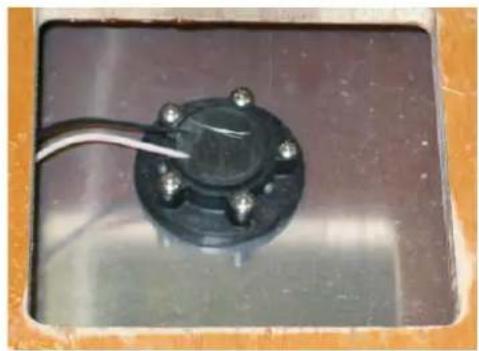
Placed at the top of the fuel tank is an electronic fuel sender. This device reads the amount of fuel remaining in the fuel tank and sends a signal to various displays including the fuel gauge located at the helm (dash). Always use the one-third rule with diesel fuel. One-third for outbound cruising, one-third for inbound cruising, and the remaining one-third fuel supply for reserve.
TYPICAL DIESEL FUEL TANK FILL/VENT

Fuel tank fill fittings are normally located on the deck. They are marked diesel. Never pump gasoline in a fuel tank designated for diesel fuel. After fueling use the fitting key tool to close the fitting tightly. Failure to secure the fuel fi tting tightly may allow water to enter the fuel tank and eventually the engine fuel system. Periodically lubricate the fuel fi tting O-ring by coating with clean diesel fuel. This will help keep the O-ring pliable and retain its scaling properties.
The fuel vent serves as a pressure relief for the diesel tank and is a safety overfl ow device. The vent is found below the fuel fi ll fi tting at the starboard hull side. It has a screen inside which needs to be periodically cleaned. Insects can cause the vent to clog resulting in increased pressure in the fuel system especially noticeable when fi lling the fuel tank. In extreme clogging cases the fuel will emerge from the fi ll because the vent is not able to relieve the air in the fuel tank that is being replaced with diesel fuel.

WARNING
PREVENT INJURY, DEATH, OR PROPERTY DAMAGE! INSPECT THE FUEL SYSTEM PERIODICALLY FOR LEAKS, OOSE CLAMPS OR FASTENERS.
TYPICAL DIESEL FUEL SYSTEM FILTERS
Diesel engines feature a primary and secondary fuel fi liter system to provide maximum engine protection. An in-line 10 micron water separator fi liter is the fi rst line of defense. In addition, Volvo provides a secondary fi liter mounted on the engine for enhanced protection from water, dirt and “algae” micro organisms/clusters.
Examine the diesel fuel in the drain container. Water is heavier than diesel fuel and will be noticed as a different color on the bottom. If water is present tilt the pan and any water will move on the bottom. In extremely humid conditions, the fuel system may require daily checks and draining of water.
ALWAYS CARRY EXTRA FUEL FILTERS AS EVEN ONE TANK OF CONTAMINATED FUEL CAN PLUG A FUEL FILTER. USE EXACT REPLACEMENTS ONLY.

TYPICAL WATER SEPARATOR DIESEL FILTER
To Drain Racor Water Separator Filter
The diesel fuel filter should be drained frequently and checked for water and other contaminants as needed:
- Place filter fuel valve in the "off" position which is perpendicular (90) degrees to the fuel lines. Failure to turn valve off may allow a continuous flow of fuel due to siphoning.
- Place a suitable container below the filter bowl assembly to catch the contaminants.
- Remove drain plug at the bottom of the filter bowl assembly. Drain the contaminants. Replace the drain plug.
- Replace the drain plug. See section on "priming."
To Prime Racor Water Separator Filter
- Loosen the air vent plug on the top right side of the fuel filter.
- Operate the primer valve until diesel fuel emerges from the air vent plug free of air. In some cases, multiple pumping is required depending on the amount of air in the fuel system. Also, it is a good idea to prime the engine secondary filter as air could be trapped in the lines.
- Close the air vent plug and tighten securely.
- Start the engine and check for leaks. If the engine is difficult to start or is rough running check to see that all connections are tight and there are no kinked fuel lines.
To Replace Water Separator Filter Element
- Place a suitable container under the bowl to collect the contaminated material.
- Turn off the fuel valve.
- Spin the element and bowl off in a counterclockwise direction using the correct filter removal tool. You can purchase these at retail auto or marine outlets.
- Remove the bowl from the element.
- Clean the bowl O-ring gland and bowl sealing surface of dirt, debris or "algae".
- Lubricate a new O-ring and the element seal with fresh diesel fuel.
- Place the new element seal into the element top with the bevel side up and the new O-ring into the bowl gland.
- Firmly hand tighten the bowl onto the element. Now attach both onto the head by hand. DO NOT USE TOOLS TO TIGHTEN!
- Prime the fuel system. Refer to the previous information.
- Start the engine and check for leaks.
Notes-Element Replacement
Contamination level varies in fuels. As the fuel system slowly plugs the element fuel flow to the engine becomes increasingly restricted.
Replace the element every 500 hours, annually, or at the first sign of power loss or hard starting which ever comes first.
Typical Secondary Engine Mounted Diesel Fuel Filter
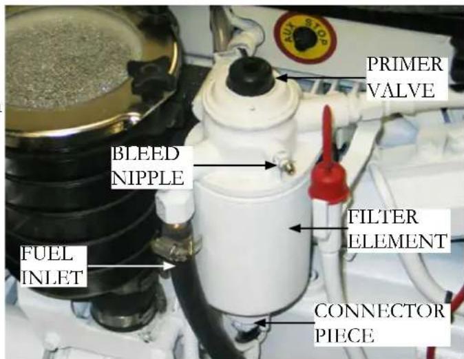
To Drain, Prime Or Replace Secondary Fuel Filter Element
Refer to the Volvo Penta operator manual for specific information. Read and understand the procedures before attempting to service the secondary engine mounted fuel filter. Follow all safety requirements and environmental regulations when servicing the fuel system.
POSSIBLE FUEL PROBLEMS/SOLUTIONS

- Engines are hard to start or rough running- This problem can be caused by air in the fuel system or a restriction in the fuel supply which causes a lean condition.
Check all fuel system lines, clamps, fittings and filters for tightness. Prime and bleed the fuel filters if necessary.
2. Fuel filter elements contain "algae" or exhibit a brown or black color and/or show water in the fuel system.
Check fuel tank for “algae” clusters. Fuel tank may require pumping out and a cleaning with a pressure washer or a biocide being added to “kill” existing organisms which may be caused by water in the fuel system and fuel tank. Replace all filter elements and top the tank with fresh diesel fuel. Prime and bleed the system. Run the engines and check for fuel leaks and restrictions along with the possibility of further contamination moving within the fuel system lines and/or components. It may be necessary to replace diesel fuel system filter elements several times to rid the system of contaminants.
- The fuel tank reads low and the engines are running rough. The pick-up tubes in the diesel fuel tank have sucked up air instead of fuel. The air has meandered through the fuel lines, filters and is effecting the engine performance. Top off the fuel tank as soon as possible. Also, the fuel system must be bled and primed.
Another possible result of running with a near empty fuel tank is the same pick-up tubes sucking water into the fuel system. Remember water is heavier than diesel fuel and will hug the tank bottom or baffle areas. Take a sampling of diesel fuel to identify water in the fuel system.
- Recommissioning after 6 months of winter storage with a full diesel fuel tank the engines are hard to start and exhibit a diesel clatter noise.
The diesel fuel in the tank may have deteriorated due to its age. The cetane value may have decreased causing more of an explosion inside the cylinder verses a controlled burn.
To start with add a cetane booster and conditioner. If this fails take a sampling of diesel system fuel at the filters.
The diesel fuel in the tank may have deteriorated due to its age. The cetane value might of decreased causing more of an explosion inside the cylinder verses a controlled burn.
To start with add a cetane booster and conditioner. If this fails take a sampling of diesel system fuel at the filters to determine contamination levels.
As a last resort pump out the fuel tank and replace with fresh, clean diesel fuel.
ELECTRICAL INTRODUCTION
In this section, basic DC (direct current) and AC (alternating current) electrical systems are introduced. Each primary electrical component is reviewed along with its location and function within the Regal electrical system. For more complicated issues outside the scope of this manual contact your closet Regal dealer. They have undergone extensive training on the Regal boat systems. Be sure to read and follow any danger, warning, or caution labels in reference to the boat's electrical system or individual equipment components.

WARNING
PREVENT SEVERE INJURY OR DEATH! DISCONNECT ALL ELECTRICAL POWER SOURCES BEFORE ATTEMPTING TO REPAIR OR REPLACE ANY ELECTRICAL COMPONENTS.
DIRECT CURRENT (12 VOLTS)
Your Regal boat uses 12 volt DC electricity otherwise known as direct current. It is called DC because it flows only one way in a circuit. Specifically to name a few, helm gauges, batteries, battery cables, engine electrical components, engine wiring harnesses, dash switches, selected lighting, shower sump, bilge pumps, and vacuum toilets are all components using a 12 volt DC system.
In the DC system used in the United States the red wire is designated as the “hot” or conductor wire and the black wire is referred to as the ground wire. At times other current carrying wires are color coded such as blue to identify their use as a low voltage conductor. This is especially helpful in troubleshooting and adding additional equipment. Be sure to review the wiring schematics in the drawing section of the technical chapter.
Direct current is stored in the ship's batteries and produced through the engine alternators while the engines are running or by the battery charger at dockside.
The alternators charge the batteries by sending current through the main distribution panel relays, battery switches and harnesses to the appropriate battery. Normal DC voltage is between 12 and 15 volts. Lower or higher readings could indicate a charging malfunction or a weak battery.
The engine alternators used on your boat are internally self “excited” and produce DC current at idle. Normal altenator output would be around 65 amps.
Typical battery circuitry includes:
The port cranking battery controls the port engine and windlass.
The starboard battery controls the starboard engine and generator.
The house battery controls a variety of onboard equipment.
BATTERY (12 VOLTS) DESCRIPTION
On board the boat's direct current (DC) is stored in the ship's "wet cell" batteries. There are 2 engine starting batteries (one for each engine) and a "house" battery. The batteries may look identical but their functions are specified and unique.
| BATTERY SPECIFICATIONS | |||
| Battery Type | Group | CCA @32 Degrees F. | Reserve Capacity |
| Engine Cranking | 31A 1190 | 0 195 min. | |
| House 31 | A 1190 | not available | |

PORT ENGINE STARTING BATTERY
STARBOARD
ENGINE STARTING BATTERY
HOUSE BATTERY
BATTERY TERMINOLOGY
Group- Batteries are divided into groups which identify the height, length, and width of the battery. This is useful information should a replacement battery become necessary.
Cold Cranking Amps (CCA)- This rating measures the cranking power a full charged marine battery has available to start at 32 degrees F. Basically, the higher the rating the greater starting power of the battery.
Reserve Capacity (RC)- As usage on the boat increases so does the need for more reserve capacity. The reserve capacity represents the length of time in minutes a new fully charged battery can maintain the boat's electrical needs without the engine running or in the event the alternator fails.
POSSIBLE PROBLEMS/SOLUTIONS

- Weak battery- This battery problem can be caused by low electrolyte cell levels.
Warm engine compartment temperatures will deteriorate a battery's life quicker by evaporating the water from the electrolyte,
thus corroding and weakening the positive grids inside the battery.
With the house battery low electrolyte levels can be monitored by periodic inspection and filling as needed with distilled water. Boaters in higher climate areas with longer stretches of hot weather will need to check their batteries more often.
If installed “maintenance free” engine cranking batteries require no water. They do feature a different chemistry that does consume less water. Inside the cells as gases are released condensation is formed which aids in maintaining the cell electrolyte level. These batteries incorporate a deeper layer of electrolyte over the plates, but eventually it can run dry.
- Dead Battery- Either the battery will not accept a charge, hold a charge or the charging system is not supplying a charging current through the battery charging system and/or engine alternators.
The battery charger output can be checked by monitoring the lights on the charger front face.
To begin with check the battery post connections for tightness and corrosion.
With the engines running the displayed voltage of the port or starboard engine battery and house battery should be between 12.5 up to 14.6 volts. If less than 12 volts check for voltage across the battery terminals.
Batteries should be removed from the vessel if necessary and trickle charged. If readings after charging are still low replace the battery.
TYPICAL BATTERY MANAGEMENT SYSTEM COMPONENTS
![graph TD A["RELAY DETAIL"] --> B["BATTERY MANAGEMENT PANEL"] B --> C["150 AMP BREAKER"] B --> D["BATTERY PARALLEL SOLENOID"] B --> E["STRO ENGINE BATTERY"] C --> F["HOUSE BATTERY"] D --> G["PORT ENGINE BATTERY"] E --> H["GENERATOR"] F --> I["150 AMP BREAKER"] G --> J["150 AMP BREAKER"] H --> K["14GA…](/content/2026/05/1030542/images/2a075918934cf3d4517e9fd8871c56942e215eb09e526e7bebc9820aae0283a1.jpg)
DVSR RELAY=DIGITAL VOLTAGE SENSE RELAY
TYPICAL REMOTE BATTERY SWITCH REMOTE BATTERY SWITCH OPERATION
As part of the battery management system remote battery switches are located in the engine room.
A remote battery switch is wired between each engine and the “on-off” universal battery switches located at the battery management system panel. See the illustration.
Their purpose is to break up the long battery cable runs from the batteries to the management center panel. Also, they offer a shorter run from the battery to the starter motor. In addition, the remote battery switch from the bilge (sump) provides an avenue to shut down the battery system during engine or sump routine maintenance functions. Remote battery circuits feature 120 volt breaker protection.

If the remote battery system fails the skipper can energize the remote battery switch manually through the magnetic latch which is located on top of the manual override switch Presently the latch features a yellow color. The energized latch permits power for engine starting.
Each remote battery switch provides a continuous rating of 300 amps DC and a cranking rating of 1250 amps DC. Normally remote battery switches are “in line” between each battery and the engine they serve.
Under normal conditions with the vessel charging system working properly each remote battery switch should show a lighted LED on the faceplate. When the remote battery switch is in the “LOCK/OFF” position the LED is not lighted.
NOTICE
IF THE REMOTE BATTERY SWITCH IS TURNED TO THE "OFF" POSITION THE ENGINE WILL NOT CRANK. TURN THE REMOTE BATTERY SWITCH TO THE "ON" POSITION FOR THE ENGINE TO CRANK. NEVER TURN THE REMOTE BATTERY SWITCH OFF WHEN THE ENGINE IS RUNNING!
- Normal operation of the remote battery switch is completely to the left in the auto or "remote" position. Notice latch position is up (disengaged).

-
To enable or connect the manual control override position of the remote battery switch turn the switch to the remote position and push the magnetic latch down until locked.
-
To disconnect the manual control override position of the remote battery switch first rotate the switch to right to release button from latch on mode (button pops up). Next, rotate switch knob to left (remote position).


- To disconnect the remote battery switch in the "Lock" position turn the switch to the right. With the magnetic latch disengaged or up the battery circuit is now off and service work on that circuit can be performed.
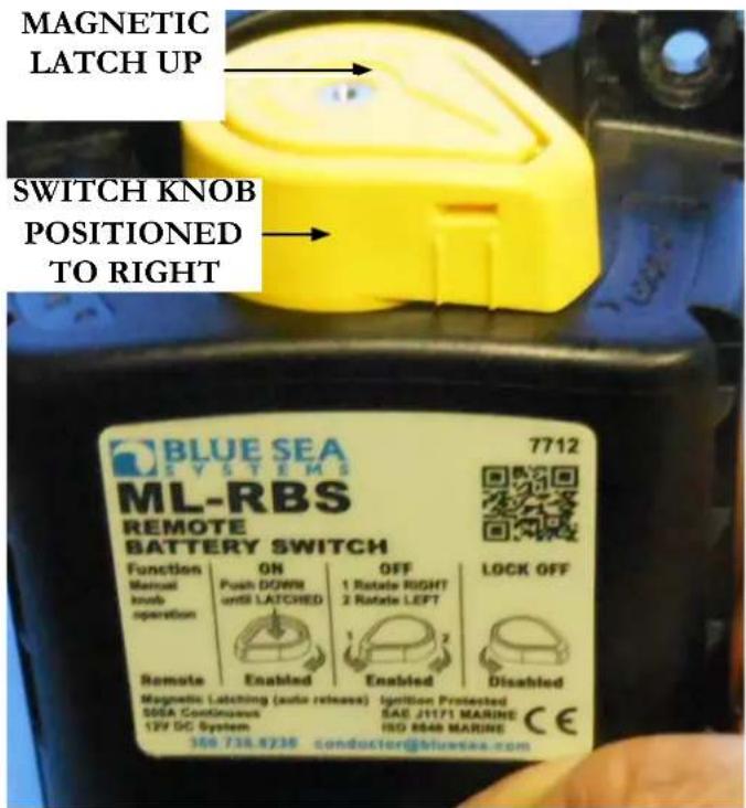
POSSIBLE PROBLEMS/SOLUTIONS
Some of the more common problems with the remote-battery switch could be:

- Engine will not crank over- The remote battery switch is in the "off" position. Reposition the remote battery selector switch to the "on" position. Make sure the magnetic latch is depressed to activate
the remote position.
- Remote battery switch in remote “on” position but engine will not crank over- Make sure the universal battery switch on the battery management panel is “on” to provide power to the helm. Check the appropriate battery connections for corrosion and tightness.
Check battery with volt meter as described earlier and a hydrometer if needed. If battery is determined to be weak press the battery parallel switch to crank the engine over or start the generator which will initiate charging of the weak battery.
TYPICAL BREAKER
As part of the battery circuit protection from the battery to the battery management system panel a 120 amp breaker is installed within 40" of the battery. These breakers are located in the bilge.
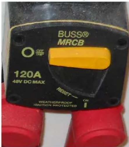
If the breaker would draw excessive amperage it is possible it could "blow". At this point it would need to be reset.
Always deter- mine the reason why the breaker blew before resetting the breaker. To reset the
breaker move the lever from the "off" position to the "on" position. These breakers are ignition protected.
POSSIBLE PROBLEMS/SOLUTIONS

-
One of the three universal battery switches and breakers at the battery management panel do not function- The breaker is blown. Reset the 120 amp breaker after determining the cause of the problem.
-
One of the 120 amp breakers has blown- it is possible that the circuit has drawn excessive amperage or there is a short circuit. Check the circuit components and wiring before resetting the breaker.
TYPICAL BATTERY CHARGER
The battery charger features 40 amp output and universal voltage for 3 battery circuits. This means that the battery charger will operate from 95 volts through 277 volts either at 50 or 60 Hz. This is helpful on docks that carry lower voltage. The new electronic battery chargers are “smart”. They will charge the batteries in 3 stages; bulk, absorption, and float formats. The charger is designated to get the maximum life out of your batteries, using micro computer controlled charging.
It is recommended to keep the battery charger “on” at all times when AC power is available for maximum battery life. We recommend checking the battery water level weekly. Fill batteries to specified levels using only distilled water. The charger is factory set to charge fl ooded lead acid batteries which are the most common type available. The charger can be reprogrammed to take gel cell or AGM batteries.
In the event the boat is switched over to different battery designs, it is important that all batteries are of the same type.
Remember, changing to a different battery type requires re-programming the charger. Do not mix different designed batteries because they need different charging rates and voltages.
During bulk charge the battery charger brings up the battery charge state quickly, as the battery nears fully charged, it switches over to absorption charge. Absorption charges at a lower rate than bulk, until the battery is just a few % away from full charge.
The battery charger display includes functional LED information for charge current, charge voltage, charge phase (bulk, absorption, float), battery content measurement and/or battery condition measurement as a % of Ah capacity.
It is recommended that an ABYC certified electrical technician perform any repairs or service. Do not attempt to open the battery charger casing.
Refer to the vendor information for more detailed instructions.
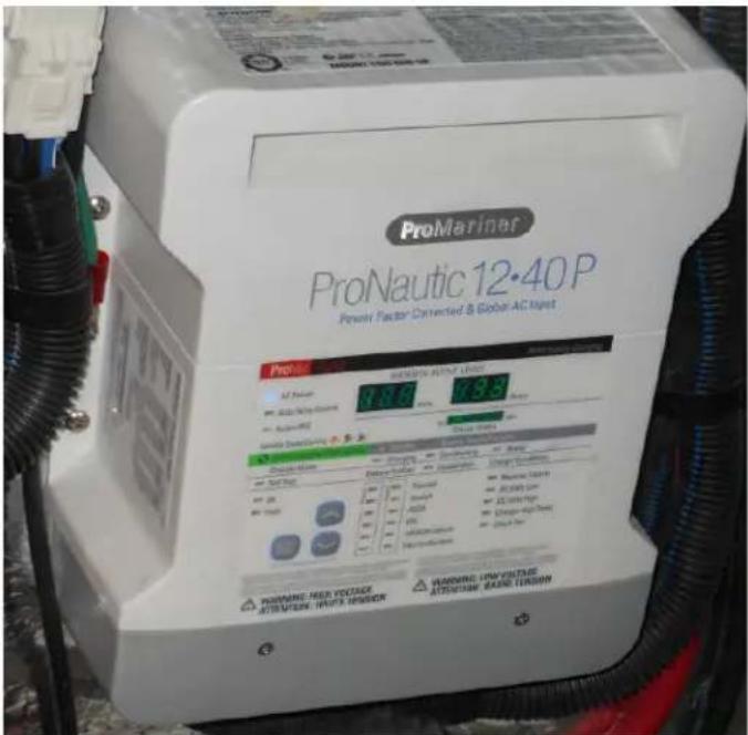
! WARNING
PREVENT INJURY, DEATH, OR PROPERTY DAMAGE FROM HIGH VOLTAGE! DISCONNECT THE AC POWER SUPPLY BEFORE ATTEMPTING TO BEGIN ANY BATTERY CHARGER SERVICE WORK.
TYPICAL CHARGING SYSTEM- SUMMARY NOTES
Following are a few notes regarding the charging system or specific charging system components.
-
With the battery charger unplugged from shore power the battery charger is not generating any DC power. However, the battery charger is connected to the batteries through the battery switches and charger breakers which are located on the battery management panel. The charger breakers would stop any short in the wires that run s directly to the battery charger. Remember that the charger is connected to the battery side of the switch and is continuously "hot".
-
There is a breaker protecting the battery charger circuit. A primary cause of the breaker to "trip" would be if the positive and negative battery cables were crossed. The above situation could easily happen if someone was trying to start a battery with "jumper cables." To a lesser degree should a wire delivering current from the battery charger chafe a fuse may "blow" and the battery charger would cease its charging operation. See your Regal dealer for ordering extra fuses for your charger.
-
If one of the cranking batteries is weak or "dead" first start the generator up and let it run awhile as it will send an initial charge to the weak battery. Then engage the battery parallel switch to start the engine.
-
Always turn the universal battery switches on the battery management panel to the "off" position when leaving the vessel for extended periods. Select breakers that control specific safety functions of the boat will operate as normal even with the battery switches off as displayed by lights engaged on the management panel.
-
When leaving the vessel after connecting your dock-side power cord turn the battery charger breaker at the management panel to the "on" position. This will permit the battery charging system to energize the appropriate batteries as needed.
-
The Bosch relay located inside the battery management panel is connected to the remote battery switch. It closes when the universal battery switch is activated at the battery management panel.
-
Remember the appropriate engine will not crank over with the universal battery switch in the "off" position.
-
An internal battery charger fuse protects the entire circuitry from reverse connections. For example, if someone was attempting to "jump" start an engine and had the polarity reversed on the jumper cables this action may cause the internal fuse to "blow" thus making the charger inoperative.
Bottom line- always remove a battery if using a trickle charger. It is not recommended to jump start using booster cables.
BATTERY E-Z CHARGE SYSTEM
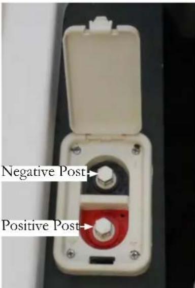
If the vessels batteries are discharged the engine hatch will not open. An E-Z charge system enables the batteries to be charged or the system can be used for attaching jumper cables to lift the hatch should the batteries be weak. The box is located inside the aft cockpit seat. To use simply follow the color coding on the
studs.
Connect a jumper cable to the positive stud and to a jumper battery (make sure you remove the red rubber cover from the positive stud). Connect a jumper cable to the negative stud and to a jumper battery. Make sure the cables do not touch and correct polarity is observed.
Follow the same procedure to hook up a trickle charger to the system.
TYPICAL BATTERY MANAGEMENT SYSTEM-PARTS DESCRIPTION

COMBINE BATTERIES (AT ARROW) FOR EMERGENCY STARTS
TYPICAL BATTERY MANAGEMENT SYSTEM-GENERAL INFORMATION
The battery management system is an important ingredient of the 12 volt direct current (DC) system. The battery management panel consists of 2 universal battery switches along with relays, DVSR's and 3 banks of DC breakers plus the wiring itself. Refer to the battery management information in this section and the technical chapter for a breaker amperage listing. Be aware that in some cases the breaker protects a component; in other cases it may control a sub-panel or parts of a sub-panel.
The universal battery switch marked port/starboard controls the engine cranking (starting) circuits.
Likewise, the battery switch marked house is part of the "house" battery circuit. The port DVSR on the panel is connected to the house circuit and the starboard DVSR is integrated into the port and starboard engine cranking circuits.
Remember that the remote battery switches and their breakers also play a role in the battery circuitry. See the earlier section regarding these components.
At this point let's look at each of the components that make up the battery management system and how the entire system fi ts together and functions as a unit.
MANAGEMENT PANEL MAIN CIRCUIT DC BREAKER CLUSTER
Port Cranking Battery- Controls Windlass Breaker
House Battery- Controls Cabin Main, Dash Main, and Electronics Breakers
DVSR (DIGITAL VOLTAGE SENSITIVE RELAY)

Located on the battery management panel are 2 DVSR's (digital voltage sensitive relays).
The purpose of the DVSR is to protect the engine batteries from being discharged. Also, when the engine batteries are fully
charged it sends current to charge the house battery.
When the cranking battery(ies) DC voltage rises above 13.4 the DVSR switches to charge (cranking and house) both batteries in parallel simultaneously. When the battery voltage drops to 12.8 volts DC the DVSR disengages.
This DVSR capability is referred to as “dual sense”. This permits the DVSR to sense the voltage of both batteries that it is connected between. If one of the batteries is receiving a charge the DVSR will close by paralleling both battery banks to charge the house battery along with the 2 engine cranking batteries.
Notice the illustration shows a LED light which indicates when lite that the DVSR is closed and is sending a charging current to a battery(ies).
If the DVCR senses the engine batteries are being discharged at a fast rate it will open and will not allow those batteries to be overly discharged to the point that the engines will not crank over.
An example of the above situation would be if the vessel was stationary at sea for an extended period with various electronic and entertainment equipment energized along with the engines and generator off the batteries would normally discharge.
POSSIBLE PROBLEMS/SOLUTIONS (DVSR)

-
Red LED light not visible at DVSR- One cause could be the remote battery switch is not energized.
-
Red LED light stays on after the engine is turned off- This is a normal
condition. The residual battery voltage because of battery charging has not yet dropped below 12.8 volts for the DVSR to cut out.
TYPICAL BATTERY MANAGEMENT SYSTEM-BREAKER SIZE/DESCRIPTION
Port Management Panel Breaker Cluster
BATTERY CHARGER- (40 AMP) This breaker protects the port battery charger circuitry.
STEREO MEMORY- (10 AMP) protects the stereo system memory circuit and the stereo unit itself.
SHOWER PUMP- (3 AMP) protects the aft/forward shower sump pump circuitry.
CO MONITOR- (3 AMP) Protects the carbon monoxide detector circuit.
COCKPIT REFRIGERATOR- (15 AMP) If installed, protects the DC refrigerator located in the refreshment center.
ACC (ACCESSORY)-(10) protects any add-on equipment components. If adding components ensure that the amperage does not exceed the safe limits of the breaker.
Starboard Management Panel Breaker Cluster
AXIUS- (20) If installed it protects the MerCruiser maneuvering system components.
AMPLIFIER- (40 AMP) protects the stereo system amp component.
FWD. BILGE PUMP- (5 AMP) protects the forward most bilge pump.
AFT BILGE PUMP- (5 AMP) protects the aft bilge pump located in the engine room floor section between the engines.
BATTERY CHARGER- (40 AMP) This breaker protects the battery charger circuitry.
Main Circuit Breaker Cluster
CABIN MAIN- (60 AMP) protects the cabin main DC panel which controls direct current switch functions throughout the vessel.
DASH MAIN- (60 AMP) protects dash operation switch functions, engine hatch panel. In addition, it controls components located on the helm breaker panel. Note that engine functions are not controlled by the dash main breaker.
ELECTRONICS- (40 AMP) protects all electronic dash equipment components along with all on board electronics.
WINDLASS- (90 AMP) protects the deck mounted anchor windlass circuitry.
POSSIBLE PROBLEMS/SOLUTIONS

- It is possible that one of the battery management system main circuit breakers may trip from long-term arcing and heat. The breaker may need to be reset- This might happen occasionally with one of the battery charger breakers.
To trip and reset this style of breaker do the following:
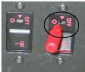
A. Take a small slotted screw-driver from your on-board tool kit and insert it in the breaker slot until it trips. You will hear a snapping type noise. See the illustration.

B. Notice that the breaker has pushed outward from its original flush position indicating the breaker has been tripped. See the illustration.
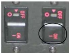
C. To reset the breaker use your finger to press the breaker down until it locks in the "on" position. You may hear a slight noise. This is normal. The icon light should be lighted after this procedure. See the illustration.
-
Breaker will not reset- Replace the breaker. Contact the nearest Regal dealer for replacement parts.
-
Breaker continues to "trip". Check the affected equipment to determine if it is responsible for the excessive draw to trip the breaker. If the equipment is determined to be within specifications check for a "short" in the wiring circuit. Also, the breaker may be faulty. Contact the nearest Regal dealer.
The battery management system panel breaker circuitry employs a lighted icon for each breaker. When lighted that circuit is energized and protected.
With both master battery switches in the “off” position the following common breaker circuits are considered “on” and should show a lighted icon above the breaker name. Below are the common breakers that will be “on” or still activated when you leave the vessel for extended periods of time with both master battery switches off at the management panel.
BOTH UNIVERSAL BATTERY SWITCHES "OFF"
- Battery charger
- Forward bilge pump
- Aft bilge pump
- Shower pump
- Stereo memory
NOTICE
AS A SAFETY FEATURE THE FORWARD/AFT BILGE PUMP CIRCUITS ARE CONTINUOUSLY "ON" EVEN WITH THE MASTER BATTERY SWITCHES IN THE "OFF" POSITION.
! WARNING
PREVENT POSSIBLE FIRE/EQUIPMENT DAMAGE! NEVER TURN A MASTER BATTERY SWITCH TO THE "OFF" POSITION WHILE THE ENGINES ARE RUNNING.
Note: As stated above the engine alternators or electronics may be damaged from the current spike created by turning off a master battery switch with the engine running.
TYPICAL MAIN DC PANEL METER/SWITCH FUNCTIONS

The typical main DC control panel is located in the aft starboard salon behind the overhead cabinet doors. This panel is protected by the cabin main breaker at the battery management center. The panel features an analog 12 volt DC volt meter and amp meter to monitor electrical voltage and load. These 2 instruments can be valuable aids in basic electrical troubleshooting.
A triple generator switch cluster facilitates gen-set operations.
A 3 amp in-line fuse located on the rear side of the panel protecting the soft indicator breaker icons.
TYPICAL 12 VOLT MAIN DC PANEL METER/BREAKER SWITCH FUNCTIONS
FWD. CABIN LIGHTS- (15 AMP) protects the overhead and reading lights.
TELEVISION- Protects cockpit television circuit.
REFRIGERATOR- (15 AMP) protects the 12 volt side
AFT CABIN LIGHTS- (15 AMP) protects overhead of the refrigerator. and reading lights.
ELECTRIC HEAD- (30 AMP) protects the salon head electrical circuit.
TV ANTENNA- (3 AMP) protects the antenna mounted on the arch.
MACERATOR- (10 AMP) protects the overboard discharge pump which when allowed pumps waste overboard. To activate first pull the cover up and then turn on the breaker.
HEAD VENT- (5 AMP) protects the head vent fan motor.
FRESH WATER- (15 AMP) protects fresh water system pump.
STEREO- (10 AMP) protects the stereo circuitry.
LEVEL MONITOR- (3 AMP) protects the fresh water and waste tank monitor located near the salon main AC panel.
BUNK ACTUATOR- (15 AMP) protects the V-berth conversion hardware that forms the forward berth bed.
BLOWER- (15 AMP) protects the engine related powered ventilation blower system (one for each engine-generator uses same blower system, activate before starting generator).
TYPICAL 12 VOLT HELM BREAKER PANEL
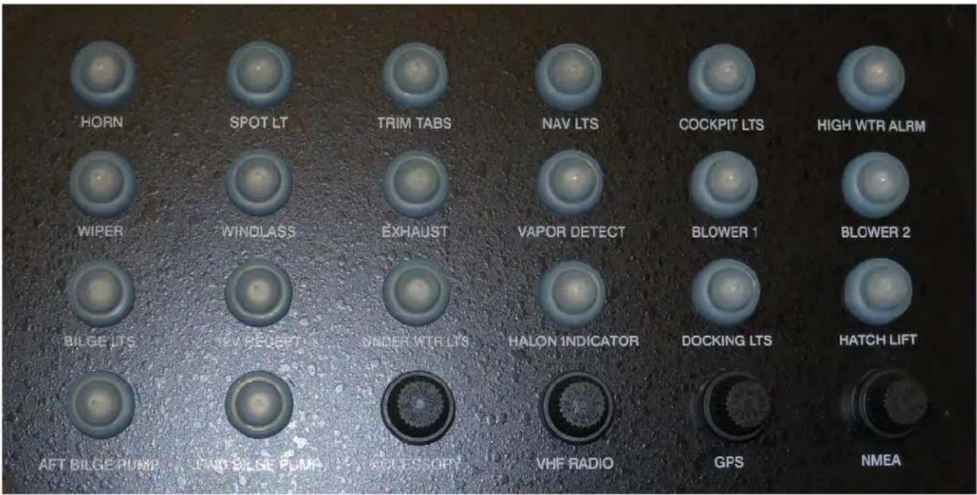
The helm breaker sub-panel protects various components located in the vicinity of the helm area. The sub-panel is controlled by the dash main breaker located on the battery management center panel.
The sub panel is located at the helm. In addition, various electronic controllers are found here.
The skipper should learn the location of all DC breakers on the vessel and the equipment they protect. For example, a breaker may trip on the sub-panel but may not trip the breaker on the battery management panel. Knowing his breaker location will aid the skipper in troubleshooting problems faster.
Remember, always find why a breaker "blows" before resetting it. Refer to the technical drawing section for additional information.
TYPICAL 12 VOLT HELM BREAKER PANEL DESCRIPTION
HORN- protects the horn circuitry.
SPOT LT- protects the deck mounted spot/search light.
TRIM TABS- protects the transom mounted electric-hydraulic trim tab circuit.
NAV LTS- protects the port and starboard deck navigation for night cruising.
COCKPIT LTS.- protects the cockpit installed light circuit.
HIGH WATER ALARM- protects the helm mounted alarm. Part of the system including the sensor float is located in the engine room.
WIPER- protects windshield wiper circuit.
WINDLASS- protects the deck mounted foot petals.
EXHAUST- protects the head exhaust blower.
VAPOR DETECT- If installed protects the gas vapor detector circuitry on gasoline powered propulsion.
BLOWER 1- protects the port powered engine ventilation circuitry.
BLOWER 2- protects the starboard powered engine ventilation circuitry.
BILGE LTS.- protects the lights in the engine room.
12 VOLT RECEPTACLE- protects the helm mounted equipment outlet.
UNDERWATER LTS.- protects the transom mounted light (under platform) circuit.
HALON INDICATOR.- protects the halon fire extinguisher system.
DOCKING LTS- protects the docking light circuitry.
HATCH LIFT- protects the hatch actuator component circuitry.
AFT BILGE PUMP- protects the bilge pump located aft in the engine room.
FWD. BILGE PUMP- protects the forward bilge pump circuitry.
ACCESSORY (FUSE)- protects the optional hydraulic swim platform circuit.
VHF RADIO (FUSE)- protects the marine radio circuitry.
GPS (FUSE)- protects the GPS chartplotter circuitry.
NMEA (FUSE)- protects NMEA 2000 network.
TYPICAL 12 VOLT HELM SWITCH PANEL

TYPICAL 12 VOLT HELM SWITCH PANEL DESCRIPTION
ARCH- activates the radar arch dual actuator system which drives the hydraulic rams to raise and lower arch.
ELECTRONICS- controls any electronics installed including chartplotter and radar.
UNDER WATER LTS- energizes the optional transom mounted under water lighting system.
EXHAUST- activates the optional Corsia engine exhaust sytem.
ACC- controls the optional hydraulic swim platform.
HORN- this toggle switch signals the bow integrated horn system blasts as needed.
NAV/ANC- energizes the bow navigation lights and the all around light.
WIPER- activates the windshield wiper on the driver's side.
DOCK LIGHTS- controls the optional hull docking lights used for night maneuvering and docking.
COCKPIT LTS- activates the LED cockpit lights installed on the deck.
| TYPICAL DC (12 VOLT) WIRING COLOR CODE & SIZES | ||
| BLACK 16,14,12,10,8,6,4,2,2/0,40 GROUNDS | ||
| BLACK/WHITE 16 HALON INDICATOR | ||
| BLACK/YELLOW 10,16 | GRD. DIESEL TRANSFER PUMP, MERC DIESEL STOP CIRCUIT | |
| BLACK/WHITE 10 HALON MAIN GRD. FEED | ||
| BROWN/BLACK 10 MACERATOR, SUN ROOF | ||
| BROWN 10 SUN ROOF | ||
| BROWN 14 AFT BILGE PUMP-MANUAL | ||
| BROWN/WHITE 14 AFT BILGE PUMP-AUTO | ||
| BROWN/RED 14 FWD. BILGE PUMP-AUTO | ||
| BROWN/BLUE 14 FWD. BILGE PUMP-MANUAL | ||
| BROWN/PINK 16 CO DETECTOR | ||
| BROWN/BLACK 16 SHOWER SUMP PUMP | ||
| YELLOW 12,10 | BLOWER | |
| YELLOW/WHITE | 16 HEAD VENT FAN MOTOR | |
| YELLOW/BLACK | 16 STEREO MEMORY | |
| YELLOW/RED 14 ENGINE START CIRCUIT | ||
Note: The list above applies to a number of vessels. Vessel components/wiring specifications may vary depending on the model.
| TYPICAL DC (12 VOLT) WIRING COLOR CODE & SIZES (CONTINUED) | ||
| ORANGE 10,12 | VACUUM TOILET,REFRIGERATOR,HATCH RAM | |
| ORANGE 16 WIPER RUN | ||
| ORANGE/WHITE 16 WIPER PARK | ||
| ORANGE/BLACK 10,12,16 HORN, HATCH RAM | ||
| BLUE 14 | INTERIOR LIGHTS, SWITCHEDCIRCUIT | |
| BLUE/RED 14 | INTERIOR LIGHTS, CONSTANTHOT CIRCUIT | |
| BLUE/BLACK 16 COCKPIT SOFT LIGHTS | ||
| BLUE/GREEN 16 INTERIOR SOFT LIGHTS | ||
| BLUE 10 | CABIN LIGHT MAIN CIRCUITFEED | |
| GRAY 14 | NAVIGATION LIGHTS, RUNNING, BOW, TRANSOM LIGHTS | |
| GRAY/BLACK | 14 | NAVIGATION LIGHTS, AFT AN-CHOR, MASTHEAD |
| GRAY/WHITE | 14 | NAVIGATION LIGHTS, MAST-HEAD, FWD. RUNNINGLIGHTS |
| RED | 16 | POSITIVE FEED- ELECTRON-ICS, GAS VAPOR DETECTOR,BREAKER TO DASH SWITCHFEEDS |
Note: The list above applies to a number of vessels. Vessel components/wiring may vary depending on the model.
| TYPICAL DC (12 VOLT) WIRING COLOR CODE & SIZES (CONTINUED) | ||
| RED/WHITE 16 WINDLASS CONTROL-DOWN | ||
| RED/BLACK 16 WINDLASS CONTROL-UP | ||
| RED/WHITE 14 BATTERY PARALLEL-LOAD | ||
| RED 14 POSITIVE FEED-ELECTRONICS | ||
| RED 12 POSITIVE FEED-ELECTRONICS | ||
| RED 10 POSITIVE FEED-AUTO PILOT | ||
| RED/VIOLET 10 | FUEL TANK TRANSFER PUMP AMPLIFIER POWER | |
| RED 8 | POSITIVE FEED- MAIN ALTERNATOR CHARGE | |
| RED 6 | POSITIVE FEED- MAIN ALTERNATOR CHARGE | |
| RED 4 POSITIVE FEED-MAIN | ||
| RED 2 | POSITIVE FEED- MAIN STARTER, BATTERY, GENERATOR | |
| RED 2/0 | POSITIVE FEED- MAIN, STARTER, BATTERY | |
| PURPLE 16 | STBD.IGNITION, HOUR METER-WINDSHIELD VENT | |
| PURPLE/WHITE 16 | PORT IGNITION, HOUR METER, WINDSHIELD VENT | |
| PINK | 16 STBD. FUEL TANK SENDER | |
| PINK/BLACK | 16 PORT FUEL TANK SENDER | |
| TAN/BLUE | 16 ENGINE ALARM CIRCUIT | |
| GREEN | 16 | TANK LEVEL MONITOR, SPOT-LIGHT |
| GREEN | 10 SPOTLIGHT | |
| GREEN | 8 BONDING | |
Note: The list above applies to a number of vessels. Vessel components/wiring may vary depending on the model.
(AC) ALTERNATING CURRENT-GENERAL INFORMATION
OVERVIEW
Alternating current sometimes called AC current is brought on board through the use of a dockside shore-power) cord or produced on board through the generator. Just as a residential home uses 120/240 volts to run various household appliances and equipment the same holds true on your cruiser.
With AC current, electrons “cycle” in one direction a short distance and reverse themselves traveling in the opposite direction. This is how AC became known as alternating current.
The rate that the current reverses itself is referred to as frequency. In the United States the alternating current frequency is 60 cycles per second. Overseas a 50 cycle frequency per second is standard. Component specifications must match the country's frequency.
BASIC ELECTRICAL TERMS
Voltage is a measurement of the electrical potential that an electrical power source contains for doing some type of work for us. Think of it as electrical pressure. An example might be your boat's battery.
Amperage is a particular amount of electricity flowing through some part of a circuit. Think of amperage as the rate of electrical flow through your boat's wiring.
Resistance inhibits the electrical flow through a circuit and is measured in ohms. An example would possibly be an incandescent light bulb. The resistance in the light bulb element allows it to glow and brighten the cabin along with giving off heat.
It is important that you understand and respect the alternating current system used on board. Be sure to read and follow any danger, warning, or caution labels in reference to the boat's electrical system or individual equipment components. Read all vendor supplied literature in the owner's information packet. Most of all, use common sense!
ALTERNATING CURRENT LOAD MANAGEMENT
Boat alternating current brought aboard through the shore power cords dockside and/or produced at sea through an onboard generator must be managed to achieve the most from the limited power available. It is completely opposite from our homes where available voltage, numerous breakers and an abundance of circuits serve an almost unlimited supply of appliances, lights and other components.
As you activate sub breakers at the main ship's panel either on shore power or generator power some desecration must be used. Monitor the load current (amperage) meter at the top right side of the main ship's panel. Note that the load current meter serves shore power 1 and 2 separately depending on the position of the on-off-on center located switch. As you activate more equipment breakers the amperage use will advance (travel to the right) at the load current meter. As you position the switch for shore 1 or 2 make sure the amperage does not exceed 30 on either circuit.
If you are using generator power do not exceed 40 amps as shown on the load current meter.
Note: The air conditioner is part of the shore 2 circuitry. In some cases it may be necessary after running the air conditioner awhile to turn the thermostat to the “fan” position before attempting to activate other breakers on the same shore 2 circuit. This will shutdown the compressor motor but the system will still circulate cooled cabin air for a temporary period. This procedure will provide more available amperage for other selected components while the air conditioner system is in the “fan” mode.
DOCKSIDE (SHORE POWER) CORD SYSTEM
The dockside cord is the basic component used to deliver 30 amps of electricity from the marina dock power box to the boat itself.
Before plugging in the dockside power cord check to see that all vessel AC breakers are off. This includes the incoming as well as both the main and equipment breakers at the AC ship's control panel. See the AC panel illustration later in this chapter.

TYPICAL 30 AMP CORD
When connecting the shore power cord be sure to twist the cord into the boat inlet plug first. The inlet plug is located on the port deck. The cord installs one way only. Align the 2 pins with the 90 degree shape, (or use the imprinted arrows and detentes located on the inlet plug) insert the cord end straight into the inlet plug and twist in a clockwise direction to lock in place. Screw the threaded sealing ring into the shore power inlet until tight. This protects the inlet and cord pins from moisture and possible corrosion build-up.
Shown below are the ship's dual 30 amp shore power inlet

plugs. The top plug is shore power line 1 and the bottom plug is shore power line 2. When not in use close and turn the covers until tight to prevent moisture from entering the plug.
TIPS-MARINA SHORE POWER STATIONS
As you become a more experienced boater you may engage in longer cruises with over night stays. It is most frustrating after a day of hard boating to pull into a marina and find your shore power cord does not adapt to the marina shore power station. This may be especially true stopping at older marinas built before the 1978 National Electric Code was enacted for these facilities. Therefore, it is recommended that you purchase several shore power adapter cords to meet various marina plug footprints.
Carry a couple extra 125 volt/15 amp adapters with a female twist 3 prong plug to a straight blade male plug with a locking screw..
Also, purchase two reverse "Y" adapter cords, one being a 50 amp, 125/250 volt straight blade crowfoot type with a grounding clip and the other being the 50 amp 125/250 volt with a locking ring.
A point to remember is that sometimes a chartplotter will provide local cruising information including marinas and facilities they offer but normally they do not provide the power voltage available at dockside.

TYPICAL MARINA SHORE POWER STATION

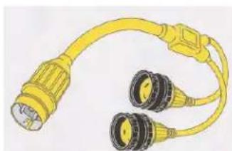
TYPICAL SHORE POWER "Y" ADAPTER CORD
Remember that your boat's main ship's panel features a reverse polarity indicator. Be sure to read that section in this owner's manual chapter since plugging into a marina distribution system is where you can find some strange wiring especially at older facilities.
Your boat shore power cord may utilize a LED light system located at the male plug end. When you plug the cord into the dock receptacle the LED light should show green indicating the current is “on”. If the LED light shows red there is incorrect wiring at the power site. Contact marina personnel immediately.
Plug the shore power cord into the marina dock power box last. This reduces the possibility of a shock hazard. Be aware there may be several types of inlet plugs located at a marina dock power center and you must be able to figure out which ones are adaptable to your vessel.
When running the shore power cord use stand-offs such as clips or velcro straps to hold the cord from touching the water. These clips or straps can be fastened to a rail or other components. In tidal zones provide for low and high tide swings. Always review the power cord layout to provide a safety zone from the water.
Also, marina dock power centers normally have breakers that must be activated after installing the dockside cord. Check with the marina dockmaster for more information on their shore power operation and requirements.
Before attempting to disconnect the shore power cord turn off all equipment and main AC breakers on the ship's main control panel to prevent any component damage.
When disconnecting the shore power cord first turn the breaker to the "off" position at the marina dock power center. Then remove the dockside cord from the marina outlet. Always remove the cord from the boat's power inlet last. Roll the cord neatly and store it in a dry environment.
Note that normally it is more likely to find a wiring problem at older facilities usually located off the main waterways where grounding problems exist or where hot wires/neutrals and even grounds are reversed although it can happen at any facility. Any of the above situations may result in your boat shore power system going from polarized to unpolarized with a potential for a fire and personal injury. Know the warning signs such as reverse polarity indicators, main power inlets or if installed ELCI breakers tripping. Contact marina personnel immediately should dock receptacles/plugs trip your on board shore power system or as explained above the red LED light shows on the shore power cord when plugged into the marina plug.
Typical domestic 30 amp dockside cords (sometimes called the shore power cord) usually contain three wires;
Black-ungrounded conductor containing 120 volts
White-neutral ungrounded conductor
Green-grounding conductor

DANGER
PREVENT BODILY INJURY, DEATH OR FIRE! NEVER USE EXTENSION CORDS OR IMPROVISED CORDS IN SHORE POWER/MARINA INLETS. USE ONLY APPROVED MARINE SHORE POWER CORDS MATCHING THE ORIGINAL WIRE GAUGE AND AMPACITY.

WARNING
PREVENT SEVERE INJURY OR DEATH!
ALTERNATING CURRENT (AC) CAN KILL YOU DISCONNECT
ALL ELECTRICAL POWER SOURCES BEFORE ATTEMPTING TO REPAIR OR REPLACE ANY ELECTRICAL COMPONENTS.
POSSIBLE PROBLEMS/SOLUTIONS

- After the dockside cord is hooked up to the boat and the marina dock power center and the AC ship's panel main breaker for shorepower 1 or 2 is activated no voltage is shown on the main panel AC volt meter.
Check the breaker on the marina dock power center to ensure it is activated.
Check the ELCI main breaker/voltage sensing device. The “power” icon should show green. If a leakage fault exists a “red” icon will light indicating the breaker is “tripped”. Use the test button to reset the breaker after the condition has been rectified.
Check the shore power cord for corrosion, faulty wiring usually at the plugs or broken twist connectors.
Notify marina personnel to verify power at the dock distribution center.
ELCI SYSTEM
TYPICAL ELCI SYSTEM OVERVIEW
The shore power terminates at the power inlet. At this point electricity when energized travels through a main ELCI breaker with leakage fault technology to the ship's main AC control panel with shore power main and auxiliary equipment breakers. The ELCI is located between the shore power inlet and the ship's main AC panel breakers.
After the shorepower inlet AC electricity travels to each of the ELCI breakers. The ELCI single pole breaker is set up to trip should an overload or fault occur between the breaker itself and the main AC control panel. If the 30 amp ELCI breaker “trips” find the cause of the problem before resetting the breaker.
The ELCI stands for “Equipment Leakage Circuit Interrupter”. There are two potential failures in a boat’s electrical system that can put people on or around a vessel at risk of lethal electrical shock. In a properly functioning marine electrical system, the same amount of AC current flows in the hot and neutral wires.
However, should electricity “leak” from this intended path in these two wires to ground, this condition is referred to as a “ground fault”. An example of this is an insulation failure in the wiring of an appliance.
Furthermore, a “faulty ground” can occur when the grounding path is broken through a loose connection or broken wire. As an example a shore power cord ground wire may fail due to fatigue caused by constant motion and stress. Faulty grounds can go undetectable; a simple continuity test may not reveal problems.
When these 2 conditions occur at the same time, it may produce tragic results. The combination of a ground fault and a faulty ground could result in the metal parts of the vessel and underwater gear to become energized. If this condition exists, besides being a hazard to personnel on board there is increased danger to swimmers near the boat. The result could be shocking people on board and swimmers could receive a paralyzing dose of electricity and drown due to a loss of muscle control.
An ELCI provides protection for the entire boat and features a trip threshold of 30mA which provides ground fault protection for the entire shore power system beyond the ELCI.
The ELCI protection on individual shore power lines combined with GFCI's will reduce the risk to those on the boat, dock, and in the water surrounding the vessel.
Notice that one ELCI breaker is marked shore power 1 and the other ELCI breaker shore power 2.
Another feature of the ELCI is a “leakage fault” detector located on the side of the ELCI breaker itself. The leakage fault feature detects a change in the neutral wire current. Should the current change more than 30 milli-amps or about 1/3 of an amp the unit senses the difference and will “trip” the breaker causing the leakage fault LED to illuminate red. This clearly indicates that the trip occurred as a result of leakage. Before resetting the ELCI breaker determine the cause of the leakage fault.
A proper operating AC system will display a green illuminated LED at the "power" marked area of the ELCI.
Periodically test the ELCI by depressing the “test” button. The breaker should “trip” indicating the system is functioning properly. Simply reset the breaker. The leakage hazard helps prevent serious equipment damage and possible fire.
After the neutral and the 2-120 volt conductors exit the ELCI they run directly to the ship's main AC control panel.
The ELCI can at times undergo a process called “nuisance tripping” which can cause a tripped breaker. This can be caused by overloads in the electrical draw or sometimes from unbalanced loads. One way to minimize the situation should it occur is to monitor closer the energized devices on the boat which will assist in keeping the total amperage used to a minimum and the loads more balanced.

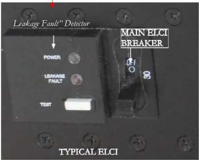
ELCI LEAKAGE FAULT DETECTOR LED INFORMATION
As an integrated part of the ELCI system there are two LED lights with a "test" button located on at the shore power inlet. With the breaker in the "on" position and the shore power cord hooked up these LED lights may show variations in color to provide system conditions. They are:
1. Green LED On- Red LED Off
Line voltage is present, the breaker is closed, and the device is protecting the circuits against over current and leakage current.
2. Green LED Off, Red LED On
The device has detected leakage current and has opened the circuit breaker.
3. Green LED Flashing, Red LED Off
The circuit breaker has opened due to overcurrent or has been manually turned to the "off" position.
4. Green LED Off, Red LED Off
Line voltage is not present. Check cord connections and marina breaker for "on" position.
5. Green LED Flashing, Red LED Off, Amber LED On
Indicates hot and neutral are reversed and the circuit breaker is open.
Note: Check circuit at least monthly by pushing in the white switch marked TEST. When depressed the breaker should return to the reset position indicating the ELCI circuit is operating properly.
For further information on the ELCI PC-S refer to the Carling web-site.
Note that both shore power 1 and 2 use the same testing procedure along with the LED detector fault system.
TYPICAL ELCI AC CIRCUIT FLOW CHART
![graph TD A["ELCI SINGLE POLE BREAKER"] -->|BLUE=NEUTRAL BROWN=120 VOLTS RED=120 VOLTS| B["SHORE POWER INLET"] A -->|GREEN/YELLOW=GRD.| C["GALVANIC ISOLATOR"] C -->|GREEN=GRD.| D["MAIN AC CONTROL PANEL LINE 1 & 2 BREAKERS"] D -->|AC BRANCH CIRCUITS.| E A -->|BLUE=NEUTRAL BROWN=120 VOLTS RED=120 VOLTS…](/content/2026/05/1030542/images/2f937c09cfed97b6d00450abc0828a52fc64146d91b85b736be58c5730f2fabd.jpg)
TYPICAL GALVANIC ISOLATOR
As part of the AC boat circuitry the green ground wire takes a different path. It enters via the boat's shore power inlet and travels to a galvanic isolator. See the illustration.
A 60 amp (60 hertz) galvanic isolator for domestic use is connected in series with the AC grounding “green” wire. Overseas boats use a 30 amp (50 hertz) galvanic isolator. The purpose of the galvanic isolator is to isolate the boat's grounding system electrically from the dock and other vessels below 1.4 volts but to maintain a connection to the shore green ground at high voltage potentials. The

low voltage isolation will prevent the vessel's zinc from protecting the underwater metal hardware on another vessel sharing the same AC common green ground wire. This eliminates the possibility of galvanic interaction from other boats on the same dock circuit and permits your anodes to protect your boat. The green ground or "bonding wire" runs from the boat's shore power inlet to a galvanic isolator stud. From the other stud of the galvanic isolator it runs to the AC ground buss located behind the AC main ship's control panel in the salon. Note that the stud nuts must be torqued and maintained at 8.8 inch pounds.
Since the galvanic isolator is not polarized either terminal can be used for the inlet or outlet side for the green grounding wire. See the illustration.
![graph LR A["30 amp"] --> B["Shore Cable"] C["30 amp"] --> D["Main Breaker #1"] E["FS60"] --> F["AC Ground Bus"] G["Line N Main breaker #1"] --> H["Line N Main breaker #2"] I["Line N"] --> J["Line N"] K["Green"] --> L["FS60"] M[" typical Isolator Wiring "] --> N[" AC Ground Bus "]](/content/2026/05/1030542/images/23006f845d141ffba9fcf2ffe4ec1022dcded9799649a8d371dc5d86e1a5e67e.jpg)
Precautions/Galvanic Isolator Warnings
Warning- It is extremely dangerous to swim or be in the marina water due to potential AC current that may be present in the water. Take all necessary precautions as this may be life threatening.
Caution- This device does not provide a status monitor. Following a lightning strike this unit may not continue to provide galvanic isolation protection.
Warning: The fan will operate only when there is a fault to ground and the isolator is conducting current. If you notice the fan running immediately disconnect the shore power and contact a qualified marine electrician to isolate and repair the problem with the boat or the shore power connection. Remember, never cover the fan holes.
Caution: Never test the isolator. Troubleshooting the gal-There is a fan located at the right side of the isolatorvanic isolator shall be done by qualified personnel only. identified by an array of ventilation holes. If you ever
hear the fan running the isolator has failed. Disconnect the shore power from the boat and check the system. Call your closest Regal dealer for more information.
Do not store objects close to the isolator that might inhibit air flow to the fan.
Note that the galvanic isolator system is also used in boats using the 50 amp main breaker (no ELCI). Normally the galvanic isolator is found in the engine room sometimes called the bilge or sump.
TYPICAL MAIN AC PANEL METER/SWITCH FUNCTIONS
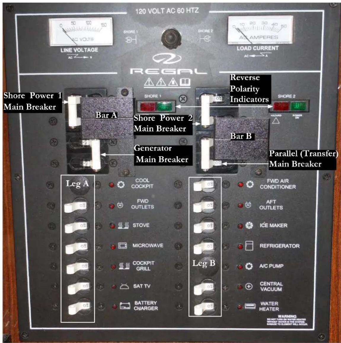
The typical main AC 120 volt control panel is located at the starboard aft salon. Lift the overhead cabinet door to gain access to the panel. The main call outs on the panel will be addressed. This panel serves as the main distribution for the incoming shore power from the marine power center or from the ship's generator when at cruise. The ship's main DC panel is located along side of the AC panel. Information on the DC panel is found earlier in this chapter.
SHOREPOWER PANEL DISTRIBUTION
As noted earlier the shore power cord delivers AC electricity through the boat's shore power inlet. The AC current travels through the vessel's electrical system to the main AC 120 volt control panel. The AC electricity is now ready to be distributed to the various equipment components.
TYPICAL AC MAIN AC CONTROL PANEL
REVERSE POLARITY INDICATOR
Before activating the panel main breaker visually check for a green light at the reverse polarity indicator. The green light indicates there is no reverse polarity. If the red light appears on the reverse polarity indicator a hot wire and ground may be reversed somewhere in the circuit from the dock to the main panel or there may be an overcurrent condition. Check the ELCI breaker as it will “trip” if a reversed polarity situation develops.
In all cases do not activate the main panel breaker. Take immediate corrective action to find the cause of the reverse polarity situation. At this point, disconnect the shorepower cord from the marina power center and call for professional assistance.
PANEL MAIN BREAKERS
The main panel breakers for Leg A and Leg B also called shore power 1 and shore power 2 deliver electricity through a system of sub breakers to the entire boat. Turn any sub breakers found “on” to the “off” position. This prevents any excessive equipment motor draws and may eliminate any system arcing.
With the reverse polarity indicator showing the green icon, activate the main breaker by pushing the single throw arm to the on position. Notice that each breaker is marked with the on and off terminology, AC electricity now is distributed to the 120 volt leg B of the panel. Follow the same procedure for the main breaker for leg A.
Turn on sub breakers as needed always being conscious of the load current meters..
50 AMP AC GENERATOR BREAKER
When the boat is under generator power AC electricity is distributed through the 50 amp main generator breaker located on the AC main ship's panel under the main breaker. See the previous illustration and the generator section for further information.
Before activating the generator AC breaker it is recommended to make sure all the equipment breakers are “off.” Next, make sure the generator is started. Slide Bar B up and activate the parallel (transfer) breaker. Move Bar A up and activate the generator breaker. The panel should now be controlled by the generator. Switch on sub panel breakers as needed.
LINE VOLTAGE/CURRENT METERS
After the shore power 30 amp main breaker or generator 50 amp breaker is activated line voltage will display on the line voltage meter of the main panel. As Leg A and Leg B volt equipment breakers are activated the load current meter (extreme right side of panel) will show an amperage draw. Normally the amperage will ascend as more equipment breakers are activated and will descend as equipment breakers are deactivated.
After the 30 amp main panel breaker or generator breaker has been activated no voltage will appear on the 120 line voltage meter at the extreme left side of the main control panel with the 120 shore power switch in the “off or center” position. This is normal. See the illustration.
The 120 volt shore power switch is located between the line voltage and load current meters. See the illustration.
As stated above with the shore power switch in the “center” position it is off. When the shore power switch is moved to the left the line voltage meter will display up to 120 volts available at leg A. As equipment breakers are activated the load current (amperage) meter will ascend and descend as equipment breakers are deactivated.
When the shore power switch is moved to the right the line voltage meter will display up to 120 volts available at leg B. As equipment breakers are activated the load current (amperage) meter will ascend and descend as equipment breakers are deactivated.
As a general note on equipment breakers when leaving the boat it is recommended that most breakers be turned off.
It may be necessary to leave the battery charger on during extended periods and the salon refrigerator. Since the refrigerator is dual voltage (12 and 120) make sure the DC refrigerator breaker is activated and the AC refrigerator breaker is deactivated upon leaving the vessel.
120 VOLT MAIN PANEL BREAKER DESCRIPTION (TYPICAL)
Leg A
Fwd. Outlets- This 15 amp breaker controls the 120 volt GFCI and outlets downstream. and the salon television.
Stove- This 20 amp breaker controls the galley stove.
Microwave- This 15 amp breaker controls the galley overhead microwave.
Cockpit Grill- This 30 amp breaker controls the salon (main stateroom) entertainment center.
Sat TV Antenna- This option is currently unavailable on this model..
Battery Charger- This 30 amp breaker controls the battery charger located in the engine room (bilge). It is recommended that when leaving the boat for extended periods this breaker be left energized in order to keep the ship's batteries in a charged condition.
Leg B
Fwd. Air Cond- This 30 amp breaker controls the forward air conditioning unit.
Aft Outlets- This 15 amp breaker controls the 120 volt GFCI and outlets downstream and the optional mid-cabin television.
Icemaker- This 15 amp breaker controls the cockpit ice-maker unit.
Refrigerator- This 15 amp breaker controls the galley refrigerator. This unit is dual voltage which means it can run on 120 volts AC or 12 volts DC electricity. See the note on the previous page regarding leaving the yacht with the refrigerator in the operational mode.
A/C Pump- This 15 amp breaker controls the air conditioning pump located in the engine room (bilge). This pump supplies water to the forward air conditioning unit.
Central Vacuum- This 15 amp breaker controls the vacuum system.
Water Heater- This 15 amp breaker protects the hot water heater installed in the engine room.
| TYPICAL AC WIRE USAGE | |
| GAUGE FUNCTION | |
| 6/4 Romex Boat Cable Generator Output | |
| 6/4 Romex Boat Cable | 50 Amp Service |
| 10/3 Romex Boat Cable 30 | Amp Service |
| 10/3 Romex Boat Cable A | /C Main Power Supply |
| 10/3 Romex Boat Cable S | love Power Supply |
| 14/3 Romex Boat Cable A | /C Pump, Power Pump Relay |
| 14/3 Romex Boat Cable R | Receptacles, Microwave, Water Heater, Refrigerator, Ice maker, Central Vacuum System |

WARNING
TO PREVENT POSSIBLE ELECTRICAL SYSTEM DAMAGE OR FIRE DO NOT TRY TO ACTIVATE SHORE POWER MAIN BREAKERS IF REVERSE POLARITY LIGHT IS DISPLAYED.
GFCI Outlet
Sometimes current in a circuit escapes its normal route and finds a “ground fault”. If that vehicle ends up to be your body and the current passes through your heart the results could be deadly.
A ground fault interrupter or GFCI senses the difference between the hot and neutral wire current before a fatal dose can be conducted and in a fraction of a second cuts the current.
The GFCI devices used in homes are normally not ignition protected. All of the Regal boat's GFCI's are ignition protected.
Your boat uses 120 volt receptacles. By using a GFCI as the first receptacle in the circuit all the receptacles down stream on the same circuit are protected by the initial GFCI. This is accomplished by attaching the hot wire to the line terminal of the GFCI receptacle and the out-going hot wire to the load terminal. The neutral wires also use line and load terminals on the opposite side of the GFCI receptacle.
You can identify the GFCI primary receptacle by the test and reset breaker in the center of the device. Check the GFCI protection monthly. If a problem develops with the GFCI circuitry call a marine electrician to access the situation.
The GFCI outlets are especially useful when electrical equipment is employed such as a drill or in the head with the use of personal devices such as curlers and hair dryers. Never use any electrical devices when puddling water is present to prevent a possible shock hazard.
GFCI'S (GROUND FAULT CIRCUIT INTERRUPTER
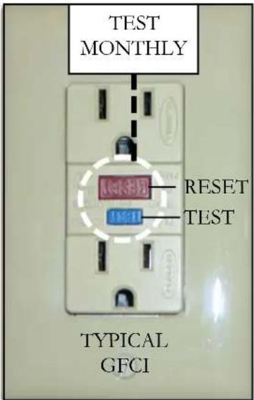
The GFCI is pro- gramed to protect a person from line to ground shock hazards which could occur from various electrical devices operating off of the device or re- ceptacles downstream. It does not prevent line to ground electric shock, but does cut down the exposure time to a fraction of a second before the de- vice trips. It does not protect people against
line to line or line to neutral faults. Also, it does not protect against short circuits or overloads; this is the circuit breakers job.
All GFCT's should be tested monthly to make sure they and the receptacles they protect "downstream" are protecting against ground-faults.
Testing GFCI'S
To test a GFCI find a 120 volt night light or small lamp to plug into the GFCI outlet. Try it in another circuit first to make sure it lights.
After the lamp is plugged into the GFCI outlet the lamp should light. Now press the “test” button at the GFCI receptacle center. The GFCI’s “reset” button should pop out and the lamp should go out. This means the GFCI itself is functioning properly. Press the “reset” button to restore power to the outlet. Test each GFCI circuit monthly. You can use the lamp to check receptacles downstream from the GFCI. All receptacles should light the lamp and should go out when the “test” button is pressed.

Also, GFCI downstream receptacles can be tested with a plug-in type GFCI tester. This tester contains a GFCI test buton which accomplishes the same thing as the GFCI receptacle built-in test button. This tester can be purchased at electrical supply houses or marine retailers.
Ignition Protected Devices
Many electrical devices in everyday use tend to “arc” or spark when being used. These include motors, fans, switches, relays, etc.
Boats in general use many of these same devices but they are protected from any sparking that may cause the device to ignite with any vapors that are typically found in the engine room and/or fuel tank compartments.
When replacing any electrical device especially in the bilge or engine room make sure it is ignition protected.
This means it has been tested and normally the device is stamped with a marking making it safe to use. Most automotive type devices are not ignition protected especially engine starters and alternators.
Note smaller hose barb for generator feed and return.
POSSIBLE PROBLEMS/SOLUTIONS (GFCI'S)

-
If the "reset" button does not pop out, the GFCI is probably defective and should be replaced.
-
If the "reset" button pops out one time but tends to stick the next the GFCI should be replaced.
-
The GFCI "reset" button pops out when something is turned on. This may indicate an internal wiring problem with the GFCI or there may be a ground-fault down stream.
-
The GFCI “reset” button is in the pressed position and nothing works. Check the appropriate breaker at the main ship’s AC control panel to make sure it has not “tripped” or as been deactivated.
TYPICAL AC GENERATOR (GEN-SET)
OVERVIEW
The generator (gen-set) is used to provide on board alternating current (AC) when the vessel is unplugged from the dockside cord or at sea. Generator frequency known as hertz is domestically set at 60 while overseas countries normally require a setting of 50. As the generator reaches full rated no load output (amps) at 60 hertz it should display est.120 volts. At 50 hertz it should display est. 230 volts at full output. The generator option is located in the engine room.
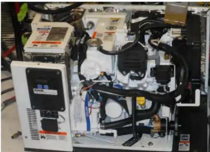
TYPICAL GEN-SET W/O SOUND ENCLOSURE
Typical Generator Fuel System
The generator is supplied by the same fuel tanks as the engines. The generator feed valve is normally marked for identification purposes. Familiarize yourself with the location of all equipment land valves.
Note: Normally the generator feed and return use a 1/4"inch barb ft tting located on the fuel tank. The feed portion will use a anti-siphon valve.
The fuel system features an in-line fuel filter located close to the generator. It's job is to keep fine particles and water out of the generator fuel system. Refer to the vendor information for periodic maintenance schedules. Clean fuel is the life line of generator performance.
The generator features a sound enclosure which reduces noise and enables quick access for most inspections, troubleshooting and routine maintenance. See the illustration below.

60
Generator In-Line Fuel Filter

Since water is heavier than fuel it will settle at the bottom of the water separator filter. Periodically check the filter for foreign debris and water in the fuel supply. To check the filter unscrew the filter using an oil filter type wrench that fits on the bottom. Do not use a strap type wrench since it may distort or damage the filter housing. Use an environmentally safe container to catch any contaminated fuel. Dispose of according to local, or state regulations.
Carry extra water separator filters on board.
When you turn the filter upside down note that any water in the gasoline will gather at the bottom of the container since it is heavier than gasoline and will appear as a different color and consistency and normally will move back and forth independently from the gasoline mixture in the container.
After inspection spin on the filter by hand until tight. Start the engine and check for fuel or air leaks.
Typical Electrical System
The generator (gen-set) starting system uses the starboard cranking battery. The generator is normally started at the 12 volt ship's control panel located in the salon but it can also be started using the remote instrument panel located at the generator itself as needed. The latter is especially useful while maintenance is being conducted..
See illustration for typical parts descriptions. Read and understand the generator operator's manual before attempting to use the generator.
NOTICE
TO PREVENT POSSIBLE GENERATOR DAMAGE ALL SHORE POWER BREAKERS AND AC SWITCHES NEED TO BE DEACTIVATED BEFORE STARTING OR STOPPING GENERATOR.
On gasoline generators start blowers and let run at least 4 minutes before attempting to start the generator. Run blowers continuously while generator is running.
Notice the power button on the "touch" control panel. Press the power button which delivers current to the start- stop button.
Press the upper portion of the start button on the "touch" control panel until the unit begins to run. Release the button. The generator circuitry allows 3-7 second cranking periods to start the unit before going into an overcrank mode.
To stop the generator run the unit at at a "no load" condition for at least 2 minutes. Next, press and hold the stop portion of the button.
Typical Generator Remote Panel (Engine Room)
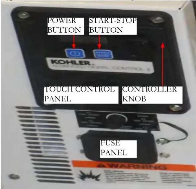
Notice the fuse panel at the bottom of the illustration. It contains 5 system component fuses ranging from 10 to 25 amps. If one of these fuses “blows” find the cause of the problem before replacing the fuse.
Note that it is a good idea to carry a set of extra fuses on board.
Typical Exhaust System
The generator exhaust system features a dual tier operation. The following items should be checked each time before As the water and exhaust exit the generator they travel to starting the generator. This covers the basic system the muffler. The muffler discharges the heavier water out components.
the muffler bottom and through the hull. The exhaust
itself is exited out the muffl er top and through the hull.
The benefits of the system are two-fold. First, the actual decibel or sound level is decreased. In addition, the lower resonating sound is more pleasing to the ear. For colder climates, a drain plug is installed in the muffler.
TYPICAL GENERATOR MUFFLER
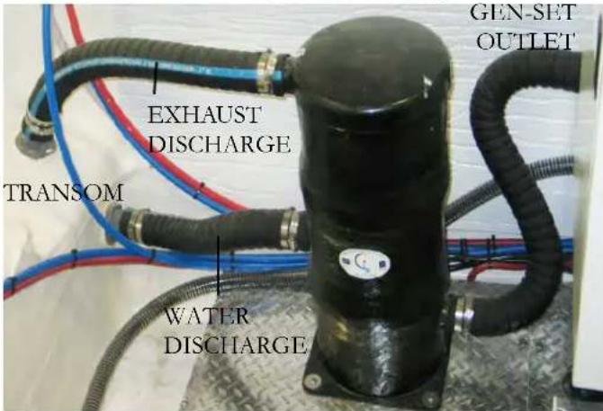
Before departure always check the hose connections for signs of water and air leaks. Tighten hose clamps as needed.
Before Starting Generator
√ Turn generator seacock off. Check strainer for debris. Turn generator seacock on before starting generator.
√ Ensure that all main panel and equipment breakers are off.
√ Inspect the generator for fuel, oil, exhaust or water leaks.
√ Check generator engine oil level. Top off with correct viscosity as required.
√ Check coolant for proper level at recovery tank. Add as needed.
√ Check the main fuel tank to ensure there is adequate gasoline for both the generator and the engines. Apply the one-third rule.
√ Check for loose wires at the alternator.
√ Check the port side cranking battery (weekly).
√ Check drive belts for wear and proper tension (weekly).
√ Record the hour meter reading to meet maintenance scheduling.
☑ Check the blowers for proper operation. Start blowers and let run at least 4 minutes before attempting to start the generator. Run blowers continuously while generator is running.
Starting Generator-Typical

The following generator starting in formation is specified for use at the ship's main control panel located in the salon. It also assumes that the
Stopping Generator
To stop the generator follow these steps at the ship's main control panel;
- Deactivate all AC equipment breakers.
checklist on the last page has been completed and all system components. Turn to the "off" position the 50 amp AC generator are in good running condition. For further information, contact breaker on the ship's AC main panel. At this point, no AC your closest Regal dealer or refer to the generator operationline voltage will be displayed at the AC volt meter. Let the manual. generator run for 3-5 minutes without a load to cool down.
-
Turn "on" the generator seacock in the engine room.
-
Stop the generator by activating the "stop" portion of the switch at the ship's main panel Hold it down until the
-
Check the ship's main control panel to ensure shore maigenerator stops running and all equipment breakers are deactivated.
-
At the lower ship's main control panel find the generator
switch. Energize the "on-off" switch and hold until the unit starts.
-
Once the generator starts, release the switch.
-
Let the generator run without a load for several minutes.
-
At the ship's main control panel slide the starboard parallel (transfer) bar up. Activate the breaker.
-
Push the port bar up. Activate the generator breaker. At this point AC voltage should display on the AC line voltage meter.

-
With generator main control panel activated there is no voltage at the AC line voltage meter. Check AC output breaker on the generator. It may of tripped due to an overload.
-
The generator quit do to overheating. Check the generator strainer for obstructions such as seaweed, plastic, or shellfish. Be sure to turn off seacock before removing the strainer basket.
-
Now it is safe to activate the desired AC equipment. The generator will not start from the main ship's panel breakers. after being serviced. Make sure the generator mounted
Note: As you are holding the switch until the unit starts it is automatically receiving the enriched fuel it needs to start.4. The generator will not crank over to start. Check the This procedure works on both Westerbeke and Kohler port cranking battery by starting the port engine. If it units at the main ship's panel. starts battery is up. Then check all generator battery con-
TYPICAL AIR CONDITIONING SYSTEM
Overview
The current optional air conditioning dual zone system is rated at 16 KW featuring a total output of 54,000 BTU's/hour (British Thermal Units) at 120 volts domestically and 240 volts internationally. The system utilizes a single 230 volt pump which delivers cooler seawater to the evaporator/condenser. Warmer seawater exits the boat through a manifold and various thru-hull fittings.
The evaporator/condenser unit incorporates a compressor located under the forward berth bunk to compact the R-22 refrigerant.
The Elite control panel (thermostat) for the forward air conditioning system is located in the main cabin (salon).
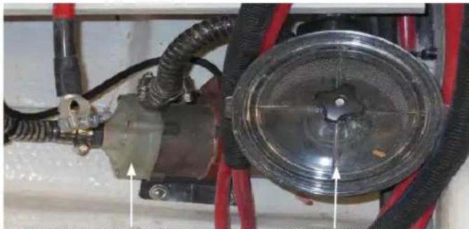
TYPICAL A/C PUMP
STRAINER
NOTE:
If the vessel is hoisted out of the water (except for winterization) make sure the A/C seacock is turned to the "off" position before lifting the vessel. Failure to do so may cause the air conditioner to loose its prime and the A/C pump may quit on start-up do to a lack of water or cause pump failure. Remember to turn the seacock "on" before re-starting the A/C unit.
TYPICAL
AIR CONDITIONING EVAPORATOR/CONDENSER UNIT

Reverse Heat
Optional air conditioning systems feature a reverse heat cycle. This can be extremely valuable to boaters in colder climates especially for early spring and late fall cruising. To accomplish reverse cycle heating, the R-22 refrigerant flows in the opposite direction through a reversing valve located on the evaporator/condenser unit. Heat is transferred from the seawater in the coil of the condenser to the R-22 refrigerant and then to the air as it is blown through the evaporator to the cabin.
Obviously, the temperature of the seawater will effect the air conditioner efficiency.
The temperature variance for cooling efficiency is:
Up to 90 Degrees F. (32.2 Degrees C.)
The temperature variance for heating efficiency is:
Down to 40 Degrees F. (4.4 Degrees C.)
Typical Air Conditioning System Operation
Below is a basic quick start-up checklist for the air conditioning system. For more in depth information, refer to the vendor operation manual.
Operations Quick Start-Up Checklist:
-
Check the AC seawater strainer for debris.
-
Make sure the AC seawater pump seacock located in the engine room is opened completely (handle should be in-line with the hose).
-
Activate the forward air conditioner breaker on the boat's main AC control panel located in the starboard aft salon overhead cabinet.
-
Check the hull side for a steady stream of seawater. Seeing water here is normal when the AC pump is running. If stream is diminished or no water emits from the fi tting immediately turn the AC pump off and investigate the cause of the problem.
-
Press the Elite thermostat Power button once to activate the air conditioning system. A blank screen displays when system is off and indicates present cabin temperature.
-
For cooling or heating press and release the Mode button until the desired LED is illuminated ie; automatic mode.
-
Press the Up or Down button to set the desired cabin temperature. To view the set point, momentarily press and release the Up or Down button.
-
Auto fan LED lights when Auto fan speed is selected.
TYPICAL ELITE AC CONTROL DIAGRAM
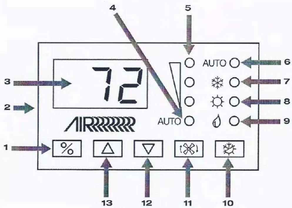
Elite Display - Diagram Legend
| 1 | Power button | 8 | Heat Mode indicator |
| 2 | Temperature sensor | 9 | Moisture Mode indicator |
| 3 | Digital display | 10 | Mode button |
| 4 | Auto Fan indicator | 11 | Fan button |
| 5 | Manual Fan indicator (high, medium, low) | 12 | Down button - Lower temperature set point |
| 6 | Auto Mode indicator | 13 | Up button - Raise temperature set point |
| 7 | Cool Mode indicator |
Note: The Elite display continually monitors the system components. Should a problem develop it sends a diagnostic code to the control (thermostaat) display. Refer to the vendor air conditioning manual (troubleshooting section) to assist in identifying the problem.
TYPICAL A/C INSPECTION TIPS
Seawater Strainer

TYPICAL A/C SEAWATER STRAINER/BASKET
The air conditioner seawater strainer located in the engine room should be cleaned periodically of debris which can inhibit or stop the fresh sea water supply.
Always turn the sea-cock handle to the off position (90 degrees to the hose fitting) before cleaning a seawater strainer.
Remove the basket by turning the plastic cap in a counterclockwise direction. Set the cap and the O ring aside.
Pull the basket from the unit, rinse with water, air dry and reinstall. Sediment at the bottom can be removed by just turning the plug in a counterclockwise direction. Place a container under the strainer to catch the sediment. Coat the O rings with waterproof grease containing a silicone or tefl on base. Reinstall O rings along with the plug and plastic cap. Turn on the seacock and check for leaks.
Return Air Filters
Once a month check the return air filter located on the face of the evaporator. To clean rinse with fresh water, air dry and reinstall.

WARNING
PREVENT SEVERE INJURY OR DEATH! DISCONNECT
ALL ELECTRICAL POWER SOURCES BEFORE ATTEMPTING
TO OPEN, REPAIR OR REPLACE ANY AIR CONDITIONING COMPONENTS.
Drain Pans
As noted on an earlier page the AC evaporator/condenser features a 2" deep drain pan connected by a hose that runs to a sump pump and eventually exits overboard. Periodically just like your home AC, the pan needs to be rinsed clean of debris and possible mold.
You can use a purchased product made specifically for cleaning AC units. Disconnect the outlet hose from the AC pan and install a made up hose (5/8") that will catch the used solution to fill a small container. Dispose of the container in accordance with federal, state and local regulations. Pour the solution into the pan and allow time for it to drain. Reconnect the original drain pan hose when finished.
Condenser Coil Cleaning
Periodically the condenser coils are recommended to be cleaned. This procedure should be done by a professional since an acid solution must be used.
POSSIBLE PROBLEMS/SOLUTIONS (A/C)

- No or little water is noticed at the thru-hull fi ttings and a HPF fault code shows on the display which means the high pressure switch is open.
The strainer or intake hose may be clogged, seacock may be closed a hose may be collapsed or the AC pump may be defective. Check AC pump breaker to verify pump is energized.
-
Air conditioner will not start. Ensure the proper AC breaker is activated on the ship's main control panel.
-
No cooling or heating. Lower or raise set point on thermostat control to offset set point being satisfied. Check for obstructed seawater flow. Remove discharge side of pump hose to purge air (air-lock). Seawater temperature too high for cooling and too low for heating.
-
Fan coil is iced. Raise or lower control set point. Clean return air filter. Switch AC to heat until ice melts or as a last resort use a hair dryer to melt ice as needed.
TYPICAL FRESH (POTABLE) WATER SYSTEM
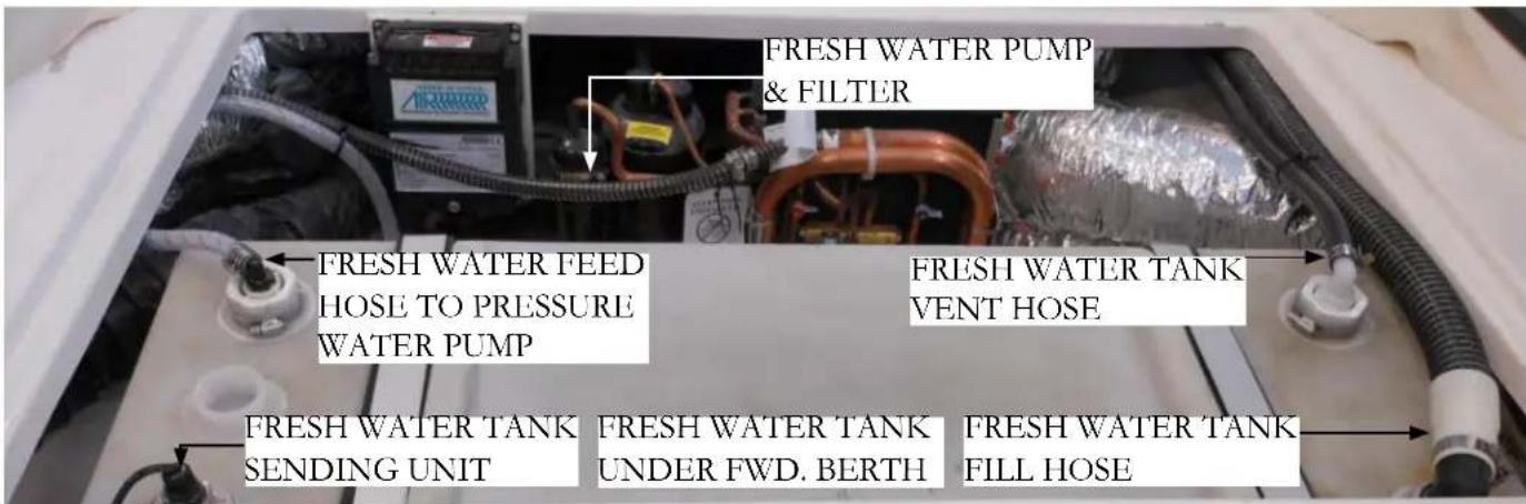
Your vessel is equipped with a fresh water supply system. It consists of a fresh water tank, deck fi ll/vent fi ttings,
monitor panel, pressure water pump with filter, distributionFill until you see water emerging from the deck vent. system, manifolds, wash down spigots and hot water heaterReinstall the fill cap and use the designed "key" to tighten As needed the pressure demand type pump is energized, or it.
the dockside system distributes water through the vessel.
The system is normally winterized from the factory utilizing a product called "Freeze Ban". It is best to completely drain the Freeze Ban before adding any water to the tank in order to minimize the taste of Freeze Ban. Freeze Ban will not harm you but it does have a peculiar taste.
The system requires little maintenance except occasional flushing and disinfecting of the tank, cleaning of the water filter and winterizing in cold weather climates.
For more specific information on the water system contact your closest Regal dealer.
The fresh water system, also known as the potable water system uses a tank to distribute water on board.
Note: There are two ways to fill the potable water system. can be filled using the fill at the forward deck. Also, locat
on the aft cockpit is a dockside water valve which connect to a hose from the marina silcock. There are special white hoses for potable water system filling that are odorless.
Before filling potable water tank disinfect entire fresh water system. Use the Public Health Service Publication information outlined in Chapter 10.
Filling Water Tank At the Deck Fill
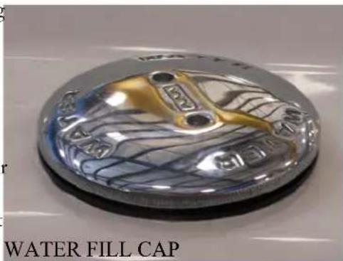
Periodically check the water fill cap for tightness. On the underside of the water fill cap is an “O ring” which aids the water fill cap to scal properly. The "O ring" should fit tightly around the leap. If it is loose, cracked or damaged replace it since it helps to keep debris out of the water system.
For general knowledge all red water lines carry the “hot” water on board your vessel. Likewise, all blue water lines carry the “cold” water.
A special reinforced fabricated hose is used to feed the water pressure pump. The design prevents kinks.
Using Fresh Water (Potable) System
-
Fill the fresh water tank(s) until water is seen at the water fill vent.
-
At the ship's main service panel activate the fresh water system breaker. This will energize the water pressure pump to send fresh water from the potable water tank through the cold water lines terminating at the various faucets and related components.
-
Open a faucet. Water pressure should be present. Opening each faucet for a few seconds will purge any air in the system especially in cases where the fresh water tank has run out of water. When water is running at a particular faucet it is not unusual to hear the water pump activate as it is trying to build up the pressure required in the system. Soon after the faucet is turned off the fresh water pump sound will end indicating the fresh water system is now up to specified system pressure.
Note: If the fresh water pressure pump continues to run long after the faucets are deactivated check for fresh water system leaks.
Note: Related to the above periodically check the fresh water monitor for fresh water tank levels. Do not run pressure water pump with system dry as water pump component damage will occur.

Fresh Water Pressure Pump
In theory the fresh water pump system provides water pressure when dockside water is not available or used. Once energized the pump is automatic. It will shut down once system pressure has built up and will automatically start after a faucet is opened. The fresh water pump and fi liter are normally located under the forward berth.
The fresh water pressure pump features a removable strainer basket filter which collects any debris which has entered the fresh water system. The clear strainer cover highlights any debris.
To clean the basket make sure the pressure water pump is off at the ship's DC control panel. Unscrew the clear cover to access the strainer basket. Remove the strainer basket, clean, rinse with fresh water and reinstall basket and cover. Do not overtighten or use tools. Turn on the pressure pump breaker and check for leaks.
Note: It is recommended that the fresh water pressure pump breaker be fl ipped to the "off" position when leaving your boat to help prevent damage should a leak develop in the hot or cold water system.

Note: In freezing climates make sure the fresh water system is winterized to prevent damage to hoses and components. Contact your Regal dealer since only special alcohol based products like "Winterban" are to be used in the system. Never use automotive type antifreeze since it is poisonous to the human body.
Operating Typical Standard Dockside Water System
At Mooring-Using Standard Dockside Water Inlet
-
Verify that the dockside water is pure and safe to use.
-
Locate the dockside inlet valve at the port aft deck. Unscrew the cap. Connect a clean hose to the boat's dockside water inlet fi tting and the marina dockside water supply. A 50 foot white hose (safe for carrying drinking water) should reach most dockside faucets.
Note: The dockside water inlet valve uses a system in-line valve that keeps the water traveling in one direction only.
-
Open the marina water supply faucet (spigot) which at this point will distribute dockside water to your boat.
-
It may be helpful to open an on board faucet to help eliminate any air in the lines.
Note that the pressure pump system is not activated using the dockside water inlet system.
At Sea-Using Fresh Water Pressure Pump System
- Energize the fresh water system breaker at the ship's main DC panel. This will permit water to flow to the appropriate faucet or component.
Note: Remember that all fresh water at sea is being delivered through the on board potable water tank. Therefore, it is important to periodically check the fresh water monitor for remaining on board quantities.
Conserve as much potable water as possible when crusing by taking shorter showers and save rinising off deck and hull if possible until you retrun to port.
! WARNING
PREVENT PROPERTY DAMAGE! DEACTIVATE THE FRESH WATER PRESSURE PUMP BREAKER AND DOCKSIDE WATER INLET HOSE BEFORE LEAVING THE VESSEL.

TYPICAL DOCKSIDE WATER INLET
Typical Monitor Panel
Sanitizing Water System
The water system features a water/waste system monitor panel which senses the amount of water left in the potable water tank system. It is located at the ship's main electrical
If the vessel has been in an extended storage condition or you suspect the water system may be contaminated, then the system should be sanitized.
control panel in the aft starboard salon.
You can purchase a water treatment kit with ingredients
To use the panel, press the switch in toward the freshwater that will sanitize the system. Follow the directions with tank position and hold. The amount of potable tank water the treatment kit. If a water treatment kit is not available will be displayed. The sender for the fresh water monitor is follow these steps to sanitize the water system.
located on the top of the starboard fresh water tank which
is located in the engine room. The key switch is used for the optional overboard discharge. Read and understand the section on using the macerator in the waste system before
- Make sure the water tank is pumped until empty. Shut off the water pressure breaker at the 12 volt ship's panel. Do not run the fresh water pump dry.
attempting to operate the overboard discharge system. Laws in many locals prevent the use of overboard discharge. A person could be severely fined so know the restrictions before using the macerator pump-out.
- Locate the potable water system disinfection information and chart located in Chapter 10 of this manual.
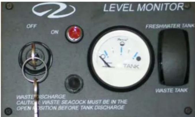
- Follow the step by step procedure outlined there using the supplementary chart as needed to mix the ingredients.
TYPICAL WATER/WASTE MONITOR PANEL
NOTICE
Do Not Use Waste/Pump-Out Before Knowing Laws/Regulations Regarding Dumping Waste.
Transom Shower
Your boat offers a hot and cold transom shower located near the swim platform. To use make sure the fresh water pressure pump breaker is activated at the ship's AC/DC control panel. Transom shower facet knobs are marked red for hot water and blue for cold water. Open the hot and cold sides and regulate the temperature. Always test the water temperature before using the shower nozzle.

Typical Hot Water Heater
Your vessel offers a hot water heater which is controlled by the generator at sea or shore power while at dockside. Like home water heaters the unit uses a T and P valve which protects the hot water tank from excessive pressure due to the water overheating. Should this occur the valve would open and direct steam overboard via the thru-hull. Also, there is a one-way valve that keeps the hot water from back flushing into the cold water supply. The hot water heater incorporates a drain valve to purge the system of mineral deposits. A reset button is found at the aft end of the component. The hot water heater may be located under the fwd. berth or the engine room.
Typical Shower Sump Pump System
Your boat features a head with a shower. As part of the drainage system a self-contained shower sump pump collects all water and debris. After the water reaches a predetermined level the float switch permits the pump to send the used shower water to an overboard thru-hull fitting or into a tank depending on the systems onboard. After showering, always let about one gallon of water settle through the shower drain to help rid the shower, drain, lines, and shower sump pump of possible debris, hair, and mineral deposits.
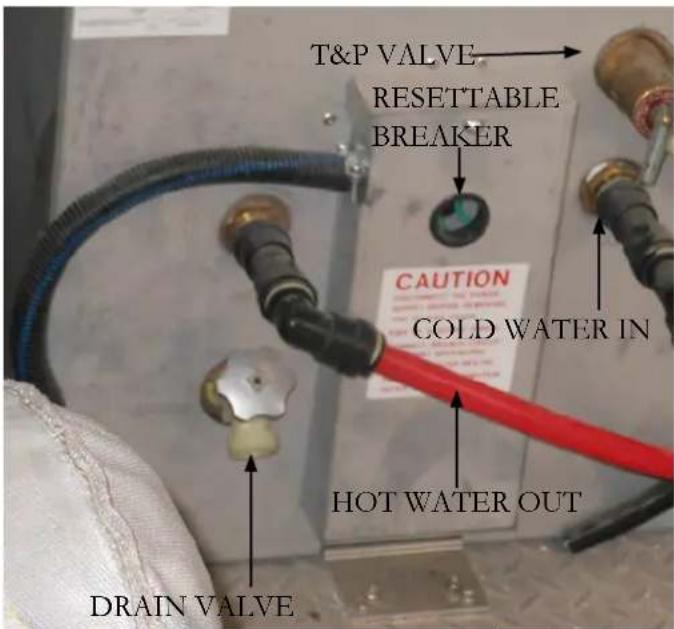
HOT WATER HEATER

TYPICAL SHOWER SUMP PUMP
Refer to the sump shower hose identification diagram for specific hose routes found earlier in the air conditioner section.
WARNING
TO PREVENT HOT WATER HEATER DAMAGE NEVER ACTIVATE THE BREAKER WHEN THE HOT WATER HEATER IS NOT COMPLETELY FULL OR THE ELEMENT WILL BE DAMAGED!
POSSIBLE PROBLEMS/SOLUTIONS-FRESH WATER SYSTEM

-
Fresh water pressure pump cycles on and off. Normally this type of action indicates a water leak in the system. Check all fresh water system related equipment on the deck, cabin, and engine compartment for leaks. Do not forget wash down equipment including spigots. Look for puddled or dripping water.
-
Using potable water system the water pressure is weak. Check the fresh water pressure pump filter for debris. Also, make sure the potable water tank level is sufficient at the monitor panel.
-
Water at sink or shower is hammering and has air bubbles in it. Check for air leaks in the system along with low water levels in the potable water tank.
-
Water is backing up in the shower. Find the shower sump pump. If it is full of water even when running there normally is a clog at the pump screen. Clean as needed.
-
There is no water at any of the fresh water related equipment such as faucets, showers and wash downs. Check to make sure the fresh water pressure pump breaker is on. Also, check the fresh water monitor for tank levels at the salon monitor panel.
-
The water system has a bad odor. Use the fresh water pressure pump to drain the fresh water system. Do not drink the water as it may be contaminated. Sanitize the water system as explained in Chapter 10.
-
There is no hot water. Turn the hot water heater breaker to the off position. Remove the back cover on the water heater and check the reset button. Push to reset. Also, the heating element may of malfunctioned. At this point, call a service technician.
TYPICAL WASTE WATER SYSTEM
Overview
The waste water system on your boat includes a waste tank located in the engine room. Besides the tank the system features a vacuum style toilet and waste pump-out ft tting mounted at the port aft deck. A monitor panel shared with the fresh water system displays the waste tank level when activated.
If installed, a macerator (overboard discharge pump) diverts waste through a hull bottom seacock (where dumping laws permit).
Gray Water System
If installed, the gray water system is used in areas where dumping fresh water waste products overboard is prohibited. Gray water originates from on board sinks and showers. With this system all the gray water is pumped into the waste holding tank via the shower sump pump system verses directly overboard. The holding tank periodically needs be to be pumped out by a marina pump out station through the “waste” fitting on the deck. Use the waste water portion of the monitoring panel at the ship’s main control panel to check waste water levels.
| WASTE TANK HOSE FUNCTIONS | |
| EQUIPMENT FUNCTION | |
| Pump Out To Pump Out Deck Fitting | |
| Vent To In-Line Vent Filter | |
| Waste-In From Forward (Salon) Head | |
| Overboard Discharge | To Macerator (Overboard Discharge Pump) Located In Engine Room |
TYPICAL WASTE WATER SYSTEM DESCRIPTION (BILGE LOCATION)

Head (Toilet) System

The onboard head system features a toilet taking advantage of minimal water usage. The system features vitreo us chi na bowl, minimal maintenance, easy cleaning and a wall switch keyboard.
The toilet is powered by 12 volt DC electricity and is controlled by a 30 amp breaker located at the ship's main DC control panel. Under normal conditions,
the head system operates from the onboard fresh water tank. If dockside water is being used the toilets still draw water from the freshwater tank.
Using Vacuum Style Toilet
To use the on board toilet first make sure the 12 volt head system breaker is activated at the main control panel. If using dockside water make sure water is connected from the marina spigot (faucet).
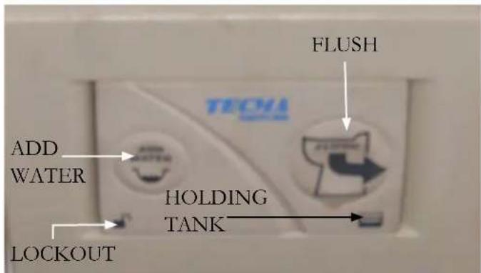
TYPICAL WALL SWITCH
A Few Notations About The Head System:
- Only human waste and toilet paper should be put in the toilet. Never fl ush foreign materials such as paper towels, pre-moistened wipes, condoms, feminine hygiene products, dental fl oss or household garbage down the toilet.
• Always disconnect the dockside water system if boat is left unattended to avoid property damage due to leakage.
- Refi ll the toilet as soon as possible after emptying the bowl to prevent objectionable odors.
- Use only RV-Marine toilet tissues that disintegrate rapidly. Do not use household type tissues.
- If repairs are needed, use only a trained and qualified marine technician or electrician.
The wall control switch is used to add water to the bowl and to flush the toilet. Select cycle information is noted below. For more complete information, refer to the toilet vendor information located in the information packet.
-
To add water (est. 17 ounces each cycle) to the bowl press the add water button momentarily and release. The system prevents overfilling the bowl.
-
To fl ush the bowl press the fl ush button momentarily and release. The attached bowl motor will macerate the waste and fl ush it. The cycle ends with a small amount of water being added to the bowl to help prevent odors. This completes the minimal water usage fl ush cycle.
Wall Control Panel Blue Backlighting Description:
- The holding tank icon in the lower right hand corner of the control panel is not lighted. Toilet system is off or not receiving power.
- The holding tank icon is normally green. This means the holding tank is less than full.
- The holding tank icon is red. The holding tank is full or near full with the flush lockout (prevents Flux operation when holding tank is full) activated.
- Tank icon fl ashes
- Sleep mode (non-use for 8 hours) causes the lights to go out. Pushing the fill or fill ush button momentarily will return lighting cycle.
Single Flush Override of Flush Lockout
-
If the holding tank is full the fl ush lockout cycle will not allow the bowl to be fl ushed and the fl ush button will be lighted red.
-
For emergency use only the flush button can be held for 8 seconds and a flush will occur. This can be accomplished objectionable odors to a minimum from the waste tank. because the full sensor connected to the holding tank. It is recommended that the filter be changed yearly. It can is usually placed a bit below the actual full capacity of the tank. Flushing more than 5 times using the override feature may force waste into plumbing system. Regal is not responsible for damage to equipment, or injury or death due to overflow of waste due when flush lockout is overridden. Again, refer to toilet vendor information in the owner's information packet.
Typical Dockside Pump-Out

There is a fi tting located on the deck labeled "waste." This fi tting is used to pump out the waste tank. Normally a pump out station is found at most marinas. After removing the fi tting cover a special hose is inserted into the fi tting and the machine then removes the waste. Normally there is a charge for the service. Make sure they connect the hose to the “waste” fi tting. Of course when cruising in international waters the overboard discharge pump may be used. See the section on using the macerator.
Typical In-Line Vent Filter
As stated earlier there is a waste filter installed in the vent line between the waste tank and the port thru-hull fitting. The filter's purpose is to keep
It is recommended that the fi lter be changed yearly. It can be ordered from your Regal dealer or from marine supply stores. The waste fi lter is mounted in the sump (engine compartment) near the waste tank.
CAUTION
POSSIBLE OVERFLOWING OF THE WASTE HOLDING TANK CAN OCCUR DUE TO USING THE SINGLE FLUSH OVER-RIDE FUNCTION. FOR EMERGENCY USE ONLY.
Typical Macerator (Overboard Discharge Pump)


The macerator (overboard discharge pump) option is located in the engine room. It is connected to a normally closed seacock. In locals where it is approved the seacock is opened and the macerator is activated through a key switch and button located at the ship's main salon control panel (shown above). At that point waste travels from the waste holding tank through the macerator pump where it is ground up and then exits through the hull bottom at the open seacool. See the photo.
To Use Macerator (If Installed):
Make sure it is legal to pump waste overboard before starting the operation.
Locate the overboard discharge seacock in the engine room. Usually this seacock can be identified by the stack of tie wraps next to it. Also, look for the incoming hose that runs from the output side of the macerator to the seacock. It is normally a 1 1/2" diameter white hose. Since the seacock by law must be have another means besides the handle to keep it closed the tie wrap serves that need. Cut the tie wrap to access the seacock handle.

Turn the seacock handle to the "open" position. It should be positioned in line as shown in the photo.
☑ Activate the macerator breaker at the 12 volt salon main DC control panel.
At the level monitor panel shown above turn the key to the "on" position. With the key switch being held in the "on" position push in on the macerator button to start the overboard discharge. Continue to discharge the waste until the monitor panel shows empty for the waste tank. At this point, shut off the macerator switch, deactivate key switch and turn macerator breaker to the "off" position.
√Close the seacock handle. It should now be at a 90 degree angle to the seacock.
√se a tie wrap and refasten the seacock handle tightly so it can not be moved.
√At this point you may desire to add an approved holding tank deodorant by flushing the correct amount down the toilet.
POSSIBLE PROBLEMS/SOLUTIONS-WASTE SYSTEM-LATER MODELS

-
Toilet does not flush or flushing performance is poor. The holding tank indicator is lighted red at the toilet control panel wall switch. The holding tank is full and needs to be pumped out. Also, there could be a clog at the water pump inlet.
-
No water in bowl during fl ush or add water cycle. Check to make sure the main water supply has not been turned off along with the fresh water pressure pump.
-
There is no light on the toilet wall control panel or it does not stay lighted. Check the head breaker on the main ship's control panel. Also, the wall panel could of entered the Sleep mode cycle after 8 hours of inactivity.
-
There is an odor of sewage onboard. Check the vent filter. It should be replaced annually at the beginning of the boating season. Also, check the waste tank, fi ttings, and related hoses throughout the vessel.
-
When running the overboard discharge pump it is not pumping out the waste. Check to make sure the deck waste cap is securely fastened and O ring is not missing (Air in system).
TYPICAL WASTE SYSTEM-VACUUM STYLE MODELS
![graph LR A["1: Fresh Water Tank"] --> B["2: System Vent"] B --> C["3: Fresh water tank"] D["4: Tolerance Pump"] --> E["5: Hold tank"] F["Solenoid Valve"] --> G["6: Fresh water tank"] H["Fresh Water Pressure Pump"] --> I["7: System can also run from dockside water supply"]](/content/2026/05/1030542/images/d325d67234dcfea46b40b4b2901b631ab252b3ca8bd1d68766a721c267506b1c.jpg)
- Toilet Bowl
- Solenoid Valve
- Fresh Water Pressure Pump
- System Vent
- Holding Tank
- Fresh Water Tank (System can also run from dockside water supply)
TRIM TABS
Trim tabs are installed on the lower hull at the transom area. Water is deflected and redirected as the trim tabs are raised and lowered from the dash switches. This change in water flow creates upper pressure under the tabs, and raises the stern. When the stern rises, the bow is lowered. Lowering the port tab will cause the port stern to rise, making the starboard bow lower. Lowering the starboard tab will cause the starboard stern to rise, making the port bow lower.
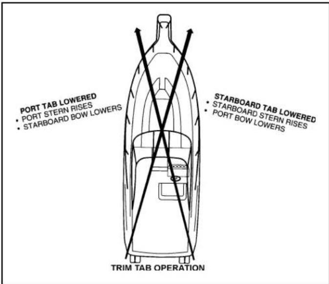
Using trim tabs will compensate for uneven weight distribution, listing, water conditions, wind velocity and other factors that cause inefficiient operation.


TRIM TAB DASH SWITCH

Obtaining A Trimmed Position
Your boat reaches a planing position at a designated speed. This speed is determined by bottom design, weight distribution, water conditions, and on board equipment. As the throttle is advanced the stern squats and the bow rises initially. The trim tabs allow your boat to plane at a slower speed than natural conditions allow.
In short bursts both trim tab rocker switches are pushed simultaneously in the “bow down” position which causes the trim tabs to move down. As the boat breaks over the bow high attitude the boat speed accelerates and visibility increases.
If the boat is over trimmed, it will plow the bow and the boat will lose maneuverability. If this occurs, simply short burst the “bow up” trim tab rocker switches simultaneously.
In the “learning curve” process, press the tab switches in half second bursts. You will notice a slight delay from the time the switches are pushed until the boat reacts depending on vessel speed. You will know after awhile the optimum planing angle and speed.
When running in heavy seas press the “bow down” position which will assist the vessel to cut through the waves. This will produce a drier and more comfortable ride.
When trimmed or in the bow down position, the bow spray is farther forward, the wake is smaller, and positioned further behind the vessel. Also, when trimmed you will notice that the tachometers show an increase in rpm's.
Rectifying A List

lowered.
Your vessel can use the trim tabs to rectify a list. The trim tabs adjust the boat's attitude in the direction the helm rocker switch is pushed.
If the port bow is high, push the left-hand "bow down" direction on the dash rocker and the port bow will lower. If the starboard bow is high, push the right-hand "bow down" direction and the starboard bow is
Trim Tab Pump
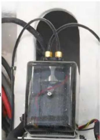
The trim tab pump is located in the aft bilge near the floor. It supplies a special hydraulic fluid to the transom based trim tab cylinders which move up and down with the rocker switches to operate the actual trim tab plates attached to the cylinders at the transom.
Periodically check the pump level. Fill with specified fluids as notated in the vendor trim tab
information. Never use the top as a step when entering the bilge from the swim platform. Also, check hose for leaks and ensure all connections are tight.
Porpoising
Porpoising is a running condition where the bow “bounces” up and down similar to a porpoise motion. Press “bow down” in one-half second bursts. As the trim tabs turn, the porpoising should recede and the vessel speed should increase. Only a small amount of “bow down” is normally necessary to make this change.
TYPICAL WINDLASS
INTRODUCTION
Using the anchor windlass requires knowledge of the anchoring process to understand the correct amount of rode and scope required. Read the section on anchoring, the windlass operation manual and understand all safety information before attempting to run the windlass. Also, since anchoring is one of the skills the skipper should master for cruising “peace of mind” visit your local library or “surf” the internet to locate further information regarding anchoring techniques.
WINDLASS SAFETY TIPS & WARNINGS
- Never use the windlass to tow or pull a boat.
- Never use the windlass for securing the anchor line. Instead use a deck cleat.
- Never drop anchor in the vicinity of divers or swimmers.
• Never wrap chain around the drum.
- Never use the windlass to pull up a person.
- Never use windlass to break anchor loose.
• Always strive under normal conditions for a 7:1scope ratio on the anchor line.
• Always remove the handle from the gipsy when operating windlass from the foot controls.
- Always turn the windlass deck switch to the "off" position when not in use.
- Always secure the anchor chain lock in "locked" position in foul weather.
• Always keep an eye on the rope/chain locker to avoid rope buiding up under the hatch.
• Always manage the retrieval process carefully to prevent the anchor from hitting the boat.


WINDLASS ANCHOR LINE
Although several variations exist the windlass is normally outfitted with 3/4 “twisted nylon line and 7/16” chain. With this combination the vessel meets normal working load conditions and the rope/chain combination protects the rode. The heavier chain lowers the angle of pull and helps bury the plow anchor which increases the holding power.
When the plow anchor is buried the chain is protected from bottom chafing as the vessel is moved around due to current, waves and wind conditions.
Several methods of securing the anchor to rode are used today including eye splices, thimbles and shackles. Regal uses a set of hexagon threaded pins which are lock tightened in place. This method provides a clean fi nish and prevents loosening due to vibration. The bolts may be removed when necessary by using a hex fi tting on a ratchet wrench.
The plow anchor featured on your vessel has demonstrated to be efficient in a variety of sea bottoms. Experts say the verdict is still out on a grassy bottom but unfortunately some grasses or weeds resist penetration by any anchor.
TYPICAL WINDLASS HARDWARE

WINDLASS COMPONENTS

SWITCH SHOWN IN "ON" POSITION
The windlass is used to automatically raise and lower the anchor. Before attempting to lower the rope/chain rode check the rope locker for tangled rope or chain. As seen in the illustration above open the deck locker to gain access to the wind-
lass switch. The switch "off" position is at 12 o'clock. With the switch "on" position (shown above) at 3 o'clock the foot switches are energized. If the foot switches have no power check the breaker located at the battery management panel.
The chain lock (stopper) is used to hold the chain portion of the anchor line assembly and does not effect the nylon anchor line. Before using the windlass make sure the chain lock (stopper) is positioned with the lever pointing toward the stern.
The chain lock “dances” or ratchets over the chain while the process of retrieving the anchor rode is underway. The chain stopper will lock the chain once the anchor is completely retrieved into the bow pulpit chute.
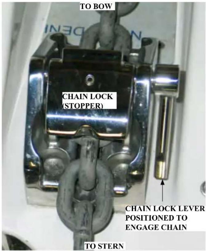
Note: Make sure the chain lock (stopper) is positioned to engage the chain once the anchor is retrieved. This prevents the chain from paying out under abnormal conditions or when a weakened gipsy clutch condition exists.

On select models bow foot switches are used to control the windlass. To use the foot switches remove the protective caps. When you energize the up foot switch the anchor is retrieved. When you energize the down foot switch the anchor is payed out. After the anchoring process is completed close the protective caps.
- Ensure both the battery switch at the battery management panel and deck foot switch are energized.
- Check the anchor rope locker for proper anchor line alignment. Untangle any crossed lines.
- Check the proposed anchoring area for swimmers or divers.
- Position vessel at proposed anchor drop site.
- Check that pawl is in disengaged position.
- Make sure chain stopper is in a released position.
- Step on the down foot switch to pay out the chain and anchor line. When the anchor hits the sea bottom disengage the foot switch.
- While the captain "bumps" the vessel in slow speed reverse pay out the anchor line until the correct scope is reached.
- When scope is reached secure the anchor line around a cleat. Never use the windlass as the sole means of holding the anchor.
- Check the anchor position by checking the postion using the GPS. The GPS features an anchor alarm. Refer to the GPS owner's manual for further information.
Retrieving Anchor
-
Check the anchor locker for any tangled lines.
-
Ensure both the battery switch at the battery management panel and deck foot switch are energized.
-
Undo the anchor line at the cleat.
-
Step on the up foot switch to retrieve anchor line as the captain "bumps" the vessel toward the anchor while maintaining a relatively straight anchor line position. Note: Breaker may blow if the captain does not bump the engines in gear due to the pressure on the windlass.
-
Once the vessel is over the anchor and it is broke free continue to retrieve the anchor. Check the anchor locker for tangled line and sweep the looped line out of the way if locker is filling up with line.
-
Once the anchor is approaching the bow slow down the windlass to ensure proper entrance at the chute and to avoid hitting the bow.
-
Once the anchor is completely retrieved "bump" the down foot switch to lock the chain.
-
As soon as possible after the cruise use the bow lock-er washdown to rinse off the anchor, chain and line. Coil the line on deck to air dry. This will aid in preventing mildew and salt deposit build-up.
Independent Warping
Once the primary rode is secure the drum can be used for docking or an additional rope only rode. To use this feature:

• Make sure the chain lock is secured.
- Pawl to be in disengaged position.
- Disengage clutch by inserting the winch handle (mounted in deck locker) in top nut and turn counter-clockwise 1/2 a turn.
- Remove handle and store in its designated location.
• The drum will operate independently from the gipsy.
- When finished using drum, insert winch handle in top nut and turn clockwise 1/2 turn to re-engage clutch.
Manual Free Fall
The anchor can be dropped without the use of battery power with this feature.
To use:
- Check that pawl is in disengaged position.
- Release the chain stopper.
- Insert winch handle in top nut. Loosen top nut by turning counter-clockwise until anchor drops.
• Control the rate of fall with handle.
• Once paid out fully tighten top nut.
To avoid possible bodily injury and/or property damage read and understand the windlass operation manual before attempting to use the windlass or anchor components.
◆ Ensure that limbs, fingers, hair and clothing are kept clear of the windlass and anchor during operation.
◆ Check to see that there are no swimmers or divers nearby before dropping the anchor.
♦ Remove the handle from the gipsy when operating the windlass from the foot controls or helm switch power.
◆ Always turn the windlass power supply to the “off” position when not in use.
◆ While at anchor, the load on the chain/rope must be transferred to a cleat.
♦ Do not use a windlass as a holding device for towing.
♦ Never use a windlass to lift a person, boat, etc.
◆ Check to make sure the permit switch is locked when the windlass is not in use.
◆ Remove the anchor safety lanyard before powering up the windlass.
♦ Fasten the anchor safety lanyard immediately after the anchor is positioned at the bow.
Do not attempt to pull a load greater than the rated load of the windlass.
◆ Always use the vessel's engines to aid anchor recovery.
♦ Refer the the windlass manufacturer's owner manual for more detailed operating and maintenance information.
TYPICAL ENTERTAINMENT SYSTEM
Antenna Switch
OVERVIEW
The antenna switch features 2 buttons labeled A and B to choose the desired antenna signal source. It is located in-Your vessel features a variety of standard components that provide both visual and audio entertainment. In addition, there are optional systems noted in the follow-
ing pages. Regal reserves the right to delete, add, or change both standard and optional components at anytime without notice.
Note: The information found in the following pages is for current models only.
Please refer to the individual owner's manuals and the technical section (schematics) for further entertainment system information along with the internet where further technical data and updates are available.
Preparing To Use Entertainment System Components
Before using any portion of the entertainment system it is necessary to activate the 12 volt "house" battery switch located at the battery management panel. In addition, the generator (at sea) or the dockside cord (at mooring) must be activated to supply AC voltage for the TV monitors.
Also, depending on the entertainment component desired the following breakers may need to be activated:
12 Volt- TV Antenna, Dash Main-Stereo (Fusion System), Television
120 Volt- Fwd. Outlets-Salon TV, Aft Outlets-Mid Cabin TV, Cockpit TV
Note: Activate the TV antenna breaker. Follow the instructions below.

At Dockside- After the television coaxial cable is plugged into the vessel coaxial receptacle located at the aft deck and the marina dock box press the A antenna switch button completely in until it catches. At this point the marina TV signal is available for onboard televisions.
At Sea- Press the B antenna switch button completely in until it catches to activate the saucer-shaped television antenna mounted on the hardtop.
To deactivate either antenna switch, push the switch completely in; then release.
When cruising you may encounter a marina without a working shore signal so your backup is to use the ship's antenna. This is more common with older marinas located off the more traveled waterways.

DVD PLAYER

TYPICAL SALON DVD PLAYER
A DVD player is found in the salon above the main ship's panel. It controls the salon fl at screen television set.
To view the salon television activate the Fwd. outlet breaker at the main ship's AC panel.
The mid-cabin television option features a flat at screen television and a DVD player. To view the mid-cabin television energize the aft cabin breaker at the main ship's AC panel.
The cockpit television option features a fl at screen television and its own DVD player. To view the optional cockpit television activate the television breaker on the main ship's DC panel.
Also, for all televisions make sure the antenna switch is positioned properly.
For more detailed operating information refer to the vendor operator's manual for each of the TV sets.
Note it is a good idea to keep extra batteries aboard for the remote controls. The batteries seem to malfunction when you need them most.
DVD-CD
Checking For Disc Compatibility
If you encounter a problem when attempting to play a disc, check to make sure it is one of the compatible types as shown below.
• Video DVD DVD
• Video CD VIDEO CD
- DVD-R, DVD-RW
• Audio CD
COMPACT
disc
DIGITAL AUDIO
- CD-R
• SACDs (CD-compatible content only)
- MP3 CDs:
— burned in a single closed session
— in disc format ISO9660
— with .mp3 as the extension and no other periods in the file name.
Disc Care
Dirt or scratches on a disc can prevent it from playing properly.
You can avoid this problem by:
- Handling all discs by their edges to prevent fingerprints and scratches. Return them to their cases after use.
- Avoiding exposing discs to chemical products that can cause damage
- Writing directly on a disc or on a label attached to the disc.
- Direct sunlight, high temperatures, and humidity.
- Always use a soft, dry and lint-free cloth to clean the disc. Wipe straight out from the center to the edge.
WIPE STRAIGHT OUT
DO NOT USE A CIRCULAR MOTION


TYPICAL STEREO

The stereo is located at the helm. The unit features an iPOD inside the waterproof cover. The newer units are bluetooth compatible for several smartphones. See photo above.
An i-POD features several adapters to cover an array of earlier and later vintage i-PODS currently in the marketplace.
The stereo breaker located at the main ship's DC panel must be activated to activate the dash stereo unit.
For more information refer to the vendor operator's manual located in the owners information packet or search the internet.
Note: Most modern electronic devices such as smartphones and tablets have a limited operating temperature range and smartphones are optimized to operate in a narrower temperature range than MP3 devices. All electronic devices generate heat during normal day-to-day use and to reduce temperature while they are being used may stop charging, the device may display a temperature warning, and eventually may shutdown if the operating temperature exceeds its specified limits.
If you are in an environment where there is a high ambient temperature and the device shuts down while inside the unit, remove it and let it cool down.
700 SERIES
iPod and iPhone Compatibility
MS-IP700 (sleeve)
MS-AV700 (cable)
MS-IP700
Before inserting your iPod or iPhone into the MS-IP700 you must first insert the correct sleeves to match the iPod or iPhone model. For the iPod nano (6th gen), the iPod must be placed inside the adaptor sleeve, and then placed inside Dock sleeve combination A + B
MS-AV700
Connect your iPod or iPhone via the standard Apple sync cable at the rear of the unit for connectivity. MS-DKIPUSB Portable Media Device Dock will connect to the MS-AV700 stereo and provide iPod or iPhone integration (Refer to the MS-DKIPUSB user manual for iPod/iPhone sleeve combinations and compatibility).
BEFORE INSERTING iPod or iPhone:
- Please ensure iPod dock connector is clean, dry & free from damage.
- Check that unit iPod dock is free from obstructions.
- Insert correct sleeve combination to match your iPod or iPhone
- Never insert an iPod or iPhone without the correct sleeve.
- Ensure your iPod or iPhone is inserted with display facing upwards, Never force your iPod or iPhone into the dock, if the unit does not mate with reasonable ease the sleeve/iPod combination is most likely incorrect.
SELECTING THE CORRECT iPod SLEEVE
(MS-IP700) A different set of sleeves is used for each iPod or iPhone model. The different sleeve combinations are outlined in the chart below:
| iPod Model | Top Sleeve | Bottom Sleeve |
| iPod touch 2nd gen | D | D |
| iPod touch 3nd gen | D | A |
| iPod touch 4th gen | D | D |
| iPod nano 4th gen | E | D |
| iPod nano 5th gen | G | G |
| iPod nano 6th gen | A | B + Adaptor |
| iPod classic, 80GB | B | A |
| iPod classic, 160GB (2007) | B | B |
| iPod classic, 120GB | B | A |
| iPod classic, 160GB (2009) | B | A |
| iPhone Model | ||
| iPhone 4 | A | D |
| iPhone 3GS | F | F |
| iPhone 3G | F | F |
USER INTERFACE AND CONTROLS
CONTROL PANEL LAYOUT
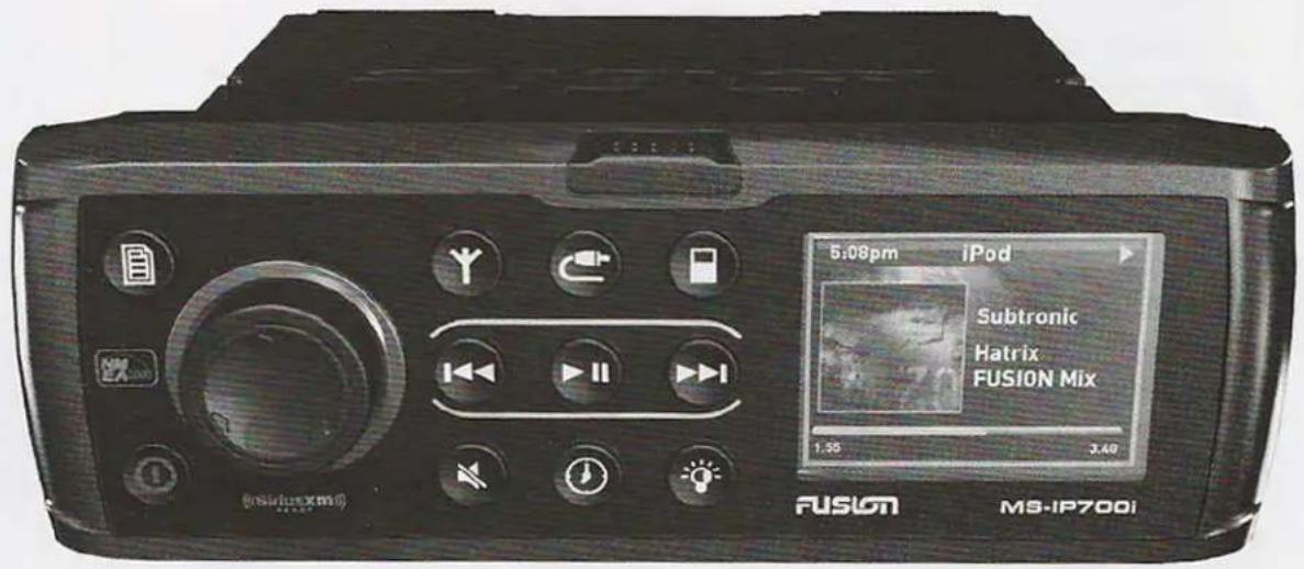
BUTTON DESCRIPTION

Menu


Power

Tuner
source

Rewind

Auxiliary

Play/Pause
PRIMARY SOURCE
MS-IP700i MS-AV700i

iPod
DVD

Mute

Clock

Forward

Brightness
ROTARY ENCODER AND MENU KEY
Although the controls of the 700 Series are designed to be intuitive to use, we recommend that you familiarize yourself with the operation of the Encoder and Menu key before using the unit.
ROTARY ENCODER OPERATION
The Encoder can be used in three ways to control the operation of the 700
Series:
| 1 |  | Rotary Encoder turn |
| 2 |  | Encoder press |
| 3 |  | Encoder press and hold down for at least one second |
MENU KEY OPERATION
You can use the Menu key to open or to exit from menus:
 | Menu key | Press the Menu key to open a menu. |
 | Menu exit | In an open menu you can use the Menu key at any time to save changes and exit:Press the Menu to exit from the current menu level or control screen.Press and hold down the Menu key to exit from the menu completely. Or press any other key.Time out feature: After 10 seconds of inactivity, the menu exits and any changes are saved automatically. |
USING THE ROTARY ENCODER AND MENU KEY
You can use the Rotary Encoder and Menu key to adjust levels, access menus and open control screens.
Adjusting levels
Use the Encoder and Menu key to adjust levels on the 700 Series.
For example, to adjust the volume level:


Turn Encoder to open the Volume screen
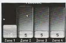


Turn Encoder to adjust the level. Press Encoder to move highlight.
Menu exit. See "Menu Key Operation" on page 6.
Accessing Menus
Use the Menu key and Encoder to access menus to change settings.
For example, to access the Settings menu:


Press Menu key


Turn Encoder to scroll the highlight. Press Encoder to select Settings menu.


Menu exit. See "Menu Key Operation" on page 6.
Highlight
Opening Control Screens
Use the Encoder to open the Sub Level and Tone control screens to adjust levels:

Press and hold Encoder for at least 1 second



Turn Encoder to adjust level. Press Encoder to move highlight.

GETTING STARTED
POWERING THE UNIT ON OR OFF
When you power on the 700 Series it will automatically start playing music from the most recently selected input source.
To power the unit on or off.

Power
- Momentarily press the Power key to power on the unit. As the unit starts up, a splash screen is displayed for several seconds, followed by the current input source.
- When the unit is on, momentarily press the Power key to power off the unit.
INPUT SOURCE SCREENS
The 700 Series supports a wide range of input source types, depending on model:
- MS-IP700i AM/FM/VHF/SiriusXM; iPod/iPhone via internal dock; USB and iPod/iPhone via external dock or cable; auxiliary.
- MS-AV700i AM/FM/VHF/SiriusXM; CD/DVD; USB and iPod/iPhone via external dock or cable; auxiliary.
Both models are also SiriusXM-Ready (USA only) requires optional SiriusXM Connect Vehicle Tuner. For further details of setting up SiriusXM options see "SiriusXM Satellite Radio" on page 49.
When you select one of these sources, the 700 Series displays a source screen, similar to the AM source screen shown in Figure 1 below. The title bar always shows the current time and source name. Other information varies depending on the source type you have selected.
Figure 1 – Example source screen (AM input selected)
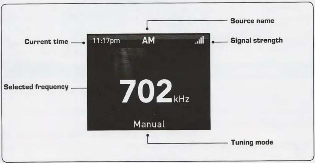
ADJUSTING VOLUME LEVEL
The 700 Series allows you to control speaker output volume level in up to four named areas called Zones. Note: Zone 3 and 4 require additional amplification.
If you wish, you can customize the settings for each Zone by defining a volume limit, a balance setting, a sub-woofer level and a personalized name (such as "Saloon" or "Galley"). For further details see "Zones" on page 40.
To adjust the volume level:
1. Turn the Encoder.
- The Volume screen is displayed with the Current Zone Selection Highlighted (remembered from previous use).
• The volume is adjusted in the highlighted Zone (or Zones) only.

- If required, press the Encoder to highlight the next Zone to adjust its volume level.
While the Volume screen is displayed, each press of the Encoder will highlight available Zones in the following order:
![graph LR A["Zone 1"] --> B["Zone 2"] B --> C["Zone 3"] C --> D["Zone 4"] D --> E["All Zones"]](/content/2026/05/1030542/images/8e09b8f233826f78733f40401bb05add07f279b5fd4df325141d77794d6e835b.jpg)
- When finished, press the Menu key (or leave to time out) to save the current volume level and exit.
MUTING OUTPUT
To mute and unmute the volume:

Mute
- Press the Mute key to mute the audio output. The Mute icon is displayed over the top of the current input source screen.
- Press the Mute key again to unmute the audio output. The volume continues at the previously set level.
iPod
PLAYING CONTENT
Before you can use your iPod as an input source you must first connect the device to the 700 Series. For further details, see "Preparing for iPod or USB Input" on page 43.
To listen to input from your iPod:
| MS-IP700i |  iPod iPod | • Press the iPod key. The iPod input source screen is displayed. The most recently selected track starts playing at the current play point.• To appear on the iPod source screen the iPod may either be inserted into the internal dock or connected to the external USB connector. |
| MS-AV700i |  Auxiliary Auxiliary | • Press the Auxiliary key. Keep pressing the key until the iPod source screen is displayed. |
iPod SOURCE SCREEN
An example of a typical iPod input source screen is shown in Figure 4 below.
Figure 4 - Example iPod input source screen

Selecting tracks from a playlist
There can be thousands of tracks stored on an iPod, so you need to select the tracks you wish to play from one of the groupings available (such as Playlists, Artists, Albums). For example, to select tracks by artist:
![graph LR A["File"] --> B["Movie"] B --> C["Albums"] C --> D["Songs"] D --> E["Podcasts"] E --> F["Genres"] F --> G["Menu"] G --> H["Menu"] H --> I["Document Icon"]](/content/2026/05/1030542/images/4a9a96361baf9933ca4d47f66613aa922b82f73b06fd85997d54ec429cf95e5f.jpg)
Press
Menu key
Turn Rotary
Encoder to scroll
the highlight.
Press Rotary
Encoder to select
Artist.
Turn Rotary Encoder to scroll the highlight. Press Rotary Encoder to select the artist or track.
Note: Additional "A, B, C..." menu may appear if FAST is enabled. See "Searching" on page 23).
Menu exit. See "Menu Key Operation" on page 6.
Controlling Playback
You can control iPod playback with the Play / Pause, Forward and Rewind keys. The selected track starts playing automatically.
| If you want to: | Use: | Notes: |
| Play / Pause a track |  Play / Pause Play / Pause | Press the key to pause the current track. The pause icon ( ) is displayed top right in the input source screen.Press the key again to resume play. The play ( ▶ ) icon is displayed in the input source screen. |
| Skip to next track |  Forward Forward | Press the key to skip to the start of the next track. |
 Rewind Rewind | Press the key to skip to the start of the current track.Press the key twice to skip to the start of the previous track. | |
| Fast forward / rewind |   Forward, or Rewind Forward, or Rewind | Press and hold down the key to fast forward (or Rewind) the playback. The fast forward ( ▶ ) (or Rewind) icon is displayed in the input source screen. |
Subtitles
- Off. Subtitles are not displayed when the iPod is playing video
- Subtitles. Subtitles are displayed
- Closed caption. Provides additional information about the track (if available)
Album artwork
Display album artwork if available
Do not display album artwork
MS-IP700i MODEL
Note: If you select iPod or USB input without first connecting the device, the message "Not connected" is displayed on the screen. Important Note: Connecting Supported iPods and iPhones to a MS-IP700i Stereo
The MS-IP700i provides two connection options for iPod and iPhone users. Supported devices may be either inserted into the internal dock or connected to the external USB connector.
The MS-IP700i Stereo does NOT support multiple iPod or iPhone devices connected simultaneously. Correct operation is only guaranteed with a single iPod/iPhone device connected.
Note; For connection to the external USB connector a Apple sync cable or external FUSION MS-DKIPUSB dock is required.
Before connecting iPod
To avoid damage and ensure safe operation, please read the following information before using your iPod.
- Please ensure iPod dock connector is clean, dry and free from damage.
- Check that the unit's iPod dock is free from obstructions.
- Insert correct sleeve combination to match your iPod (never insert iPod without the correct sleeve).
- Ensure iPod is inserted with display facing upwards.
- Never force your iPod into the dock, if the iPod does not mate with reasonable ease, the sleeve/iPod combination is most likely incorrect.
• Take care when removing iPod from unit as surfaces may be warm.
To insert your iPod:
- Press the door catch and open the control panel door.
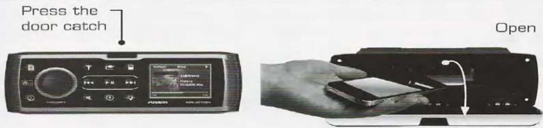
- Insert your iPod in its sleeve (see iPod compatibility sheet supplied separately). Make sure that the device is firmly pushed onto the connector socket.
- Close the control panel door firmly.
- Select input from the device, as required.
MS-AV700i and MS-IP700i Models
The 700 Series stereos provide an external USB connector (rear cable assembly) for connection to external iPods, iPhones, USB storage devices or FUSION MS-DKIPUSB dock.
To connect your iPod, you will need:
- Portable media device dock (MS-DKIPUSB), or
- Apple Sync Cable.
To connect your USB flash drive, you will need:
- Portable media device dock (MS-DKIPUSB), or
- Connect your USB flash drive directly to the external USB cable.
Note: If you select iPod or USB input without first connecting the device, the message "Not connected" is displayed on the screen.
ELECTRONICS-TYPICAL
Your boat features several electronic options. If installed, they may include a chartplotter, radar, VHF radio with DSC capability and XM satellite weather radio. Operating information for electronics can be found in the owner's information packet.
Please refer to each vendors owner's manual for in-depth information regarding individual electronic components.
Regal reserves the right to upgrade, change, modify, or eliminate any system or component at anytime.
System Operation Overview
To operate dash electronics the following switches need to be energized:
- Make sure the battery switch is activated. To perform this function turn the "house" battery switch to the "on" position as shown by the arrow in the illustration.
- Activate the "electronics" switch at the helm panel which controls power to the GPS antenna.
- At this point each individual component can be activated.

Notice the electronics breaker as shown above by the white outlined rectangle. If the electronics components do not power up, check to ensure this breaker is activated. Always find the source of a tripped breaker problem before reactivating it. Press the breaker in to reset it.

Electronics: Helm Switch
Chartplotter
The unit features a touchscreen, NMEA 2000 compatible, multifunction display, pre-loaded with U. S. coastal maps and interfaces with other electronic components It displays graphics with crisp, video-quality resolution.
Chartplotter Operation
Before operating the chartplotter read and understand the vendor supplied owner's manual including all the warning information.
These chartplotters feature “touch” screens. When you see information groups on the screen use your finger to touch the format desired. With some information in particular it is required that you actually drag an object by using your finger and keeping it on the screen as you move the object.
A. To power the system the “house” battery needs to be activated by the battery switch at the battery management panel.
B. Next, turn the helm electronics switch to the “on” position. This powers up the GPS antenna and the auto pilot. The chartplotter is now ready to power up.
C. Press and release the chartplotter power key. When the warning screen appears, touch I agree. At this point you will be taken to the home page screen.
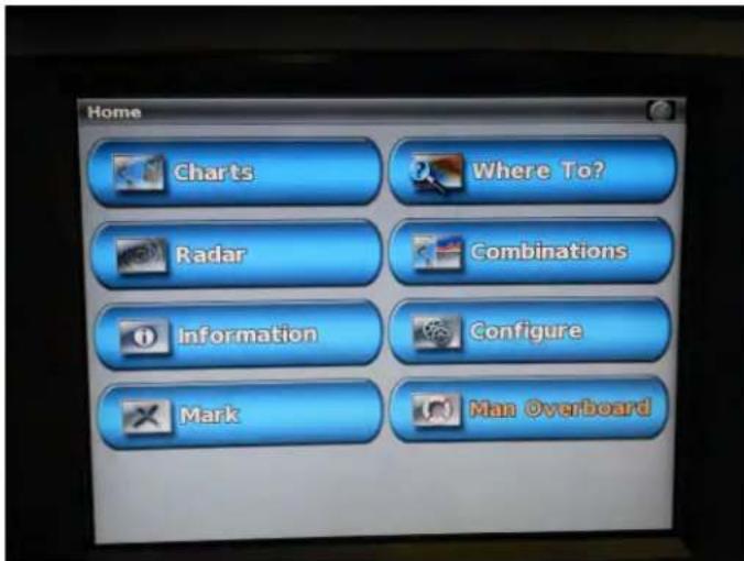
Home Screen
Charts- Selects navigational charts and radar overlay functions.
Radar- Sets up and provides sonar information through the optional transducer.
Information- Shows tide conditions, currents, celestial data, information about other vessels, your yacht's instrumentation, and video.
Mark-Marks, edits, or deletes your current location as a waypoint or Man Overboard
Where To?- Searches and navigates to service areas, routes and waypoints.
Combinations- formats screen to view a chart, sonar, radar, and video cameras (2 cameras on each chartplotter; requires the extra chartplotter option).
Confi gure-Permits the editing of chartplotter system settings (Can set a simulator mode where you can practice using most of the chartplotter functions).
Man Overboard-Marks your current position as a waypoint, and sets a course back to the marked location.
Once you are able to navigate to the home screen each of the electronic onboard components can be formatted and adjusted to meet individual needs and the finer points of cruising requirements. Continue to read the electronic owner's manuals for adjusting the finer settings on the chartplotter(s).
Typical Radar
Since the optional radar unit is part of the vessel electronic marine network you will be able to use the chartplotter as your network screen and have the capability to overlay the radar image on the chartplotter map page. The closed array radar unit is normally mounted on the power tower along with the TV antenna.
Radar Operation
Read the radar operator's manual for learning all the features of the radar component. It is a good idea to use the manual along side the chartplotter to learn the basic radar operation. At that point you can branch out with the manual on the secondary functions of the radar. Pay special attention to all safety and warning labels in the operator's manual.
! WARNING
RADAR PRODUCES ELECTROMAGNETIC ENERGY WHICH IS HARMFUL. TURN THE RADAR OFF WHEN PERSONNEL ARE SERVICING THE UNIT OR EQUIPMENT CLOSE BY.
! CAUTION
AVOID POSSIBLE DAMAGE TO THE EYES DUE TO ELECTROMAGNETIC ENERGY. WHEN RADAR IS TRANSMITTING DO NOT LOOK DIRECTLY AT THE ANTENNA AT CLOSE RANGE.

Typical Engine Management System
Read and understand the chartplotter owner's manual before setting the engine management function to gain in-
If installed, the digital gauges can be displayed on theight into the engine gauge screen selection process. chartplotter(s) through the home screen. Touch information, helm gauges and engine menu.
Also, at the home screen helm gauges can be accessed by touching combinations. From the next screen, pick the desired combo. Go to menu, change combination and choose the desired function 1-4.
By using the > and < symbols you can access the different gauge combinations and choose the one gauge screen or multiple gauge screens for that function.
Read and understand the chartplotter owner's manual before attempting to operate the vessel using these chart-plotter functions.

Typical VHF Marine Radio
The optional VHF marine radio features up to 25 watts of transmitting power and DSC capability. There are dedicated soft keys linked to a screen to select and view the information the yachtsman needs.
The radio is interfaced to the chartplotter which permits you to obtain mayday signaling and a digital broadcast of your boat's position. The unit offers premium sound quality so each message is loud and clear. Also, the VHF receives NOAA weather alert information.
Read and understand the vendor supplied information on the operation of the unit. Be sure to train a crew member on how to use the VHF marine radio should the captain become unable to carry out his duties.

Engines & Controls
OVERVIEW- FUNDAMENTALS

This chapter introduces the propulsion system-engine and drive. This is not to be thought of as a complete workshop manual. This manual will highlight a portion of the engine and drive information Read the
Volvo or MercCruiser engine manual carefully and understand the operation as well as the necessary maintenance requirements of the engines and related drive system components before operating the vessel. Contact your closest Regal dealer or repair facility for maintenance or parts needs.
Always begin maneuvering in a controlled environment where you can practice shifting and docking operations at your own pace. Learn how the vessel's engines and propulsion systems behave at different speeds, in varied sea conditions, and under light and heavy loads. Always keep the safety of others in mind as you practice docking.
Learn to monitor the helm gauges, electronic equipment, and warning systems as they are your on board friends. Read all safety labels and practices. Review with a crew member all the component operations in case the captain would become unable to carry out his duties as skipper.
Note: Your Regal dealer has been factory trained on the various vessel systems. Consult your Regal dealer for further information regarding technical support and parts.
! WARNING
AVOID SERIOUS INJURY OR DEATH! READ ALL MANUFACTURER'S ENGINE AND PROPULSION MANUALS BEFORE STARTING OR OPERATING THE VESSEL.
! CAUTION
NEVER RUN ENGINES WITHOUT WATER. DAMAGE TO THE WATER PUMP, IMPELLER, AND OTHER ENGINE PARTS WILL OCCUR.
ENGINE BREAK-IN: ALL MODELS
All propulsion systems require a pre-determined “break in” period. During this time the engine should not be run at a full load condition for extended periods. Various engine load and speed conditions assist the internal engine parts such as bearings, valves and piston rings to “seat” properly which will help ensure a longer engine life. See operator’s manual for further information.
During the “break in” period it is necessary to check the engine oil more frequently since it is normal that the engine will use more oil. If engine oil is required be sure to check the engine manual for proper grade and viscosity. Check the maintenance schedule in your engine owner’s manual and contact your Regal dealer to set up the first maintenance inspection. Normally the engine oil, fl liters, and drive oil inspections and maintenance are performed during this inspection along with other items.
Never exceed a 12 month period between oil changes especially with diesel power since sulfur tends to enter the lubrication system through the fuel combustion process over a period of time.
OIL CHANGES (ENGINE & DRIVE)
Be sure to read the owner's manual regarding engine oil change recommendations along with stern drive oil. Be sure to follow the engine manufacturer's recommended oil type and viscosity. The engine oil change is an important factor in obtaining engine longevity since impurities enter the crankcase through the combustion process and build up in the engine oil.
Be sure to check the drive oil on a periodic basis and change it using the recommended type per the engine owner's manual.
VENTILATION SYSTEMS
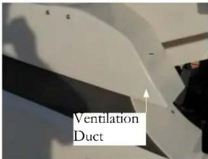
With marine engines select amounts of air are required to perform the combustion process. The higher the revolutions per minute of the engine the more air is required to meet the demand. A natural and powered ventilation system are incorporated with gasoline powered engines.
Unlike gas engines diesel engines exhaust large amounts of incoming air by mixing it through the combustion process and forcing the air through the engine exhaust system into the water. The same deck cowlings are used to funnel incoming air for combustion. The remaining air exits through the cowlings into the atmosphere.
This “breathing cycle” occurs naturally within the diesel with more oxygen being required as the throttle speeds are increased.
As part of periodic maintenance, ensure the cowlings are free of debris including animal nests such as wasps and birds. Check and replace the engine air filters as required. See your nearest Regal dealer for filter parts.
Also, it is recommended that after a cruise you let the engines and generator idle under a 'no load' condition for several minutes. Perform a visual check for exhaust and fluid leaks in the bilge. Since there is a light gelcoat color in the bilge bottom it will be easier to spot any fluid leaks.


IGNITION SWITCH PANEL
Ignition key switches normally feature the following positions to identify key operating areas.
S= Stop
I= Operating Position (Ignition On)
II-III=Start (Spring Loaded)
NOTE: Turn the ignition key to the right “OPERATING” position and then to the spring loaded “START” position. At this point the key can be released and the engine will crank until it starts. To stop the engine, return the key to the “off” position. On select engines the stop position is straight up and down; others the stop
Notice the areas above outlined in red as they refer to function is at a 180 degree position.
important safety information. Read and understand the blower information before attempting to start the engines.
The blower switch above is used on all gasoline engines.
Before turning on the blower switch do a snife test by opening the engine hatch. At the same time check fuel tank components. When assured the bilge is clear of any fumes turn on the blower switch for at least 4 minutes before attempting to start the engines. This will vacate any gasoline fumes that are in the engine room (bilge or sump). Continue to run the powered blower system below cruising speeds after starting the engines.
Diesel engines on the other hand relay on natural ventilation as the soul ingredient to develop engine horsepower and to purge the bilge area.
The areas in yellow represent 20 amp ignition system breakers. There is one breaker per key switch. These breakers protect the ignition switch circuitry. Should a breker “pop” find the cause of the malfunction before attempting to restart the engine.
VOLVO AUX. STOP SWITCH
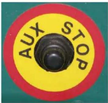
On diesel power only should the key switch fail to shut down the engine there is an auxiliary stop switch located in the sump on the side of each engine. Depress the button until the engine completely stops. See the illustration.
Newer Volvo propulsion packages feature the advanced E-key technology. This system consists of two main components; the key panel and the key fob. The key panel used is engineered for both engines to be started independently after one swap of the key fob. The same key fob motion is used to stop the engines.
If a key gets lost you can easily remove that key from the approved key listing and approve another one as a replacement. If all keys get lost the VODIA tool must be used to add new keys to the system.
This system supplies a high level of theft protection.
NOTICE
TO PREVENT ELECTRICAL SYSTEM DAMAGE, NEVER TURN "OFF" THE BATTERY SWITCHES BEFORE IGNITION KEY IS REMOVED OR IN THE "O" POSITION.
NOTICE
WITH THE ELECTRIC BATTERY SWITCHES IN THE "OFF" POSITION THERE IS NO POWER TO THE DASH KEY SWITCHES.


There is a start-stop switch for each engine. Refer to the Volvo operator's manual for more information on the E-key system.
32 EXPRESS HELM OVERVIEW (TYPICAL)

Note: Various components above are optional. Location and equipment shown may change at any time.
INSTRUMENTATION (TYPICAL)
The helm station (dash) is equipped with a set of instruments (called gauges) specifically designed to monitor the condition of the propulsion components and other onboard equipment. Close observation of the gauges is the responsibility of the captain while cruising. Periodically scan the gauges for the appropriate meter level deflections. Other instruments called displays present digital information verses needle deflection. Become familiar with all the gauge functions and their normal operating specifications as outlined in this manual and your engine operation manual. Gauge deflection (movement) on boats is very similar to automobiles. After educating yourself in the functionality of the instruments be sure to train another person as the skipper's backup. This person should know how to read the gauges and how to respond to system "fault" codes should they occur.
The digital tachometer (tach) indicates the speed of the engine in revolutions per minute (rpm). Marine engines feature rev limiters to keep the engine rpm's within safe limits. Select tachometers display the engine running hours.

Fuel Gauge
The fuel gauge indicates the level of fuel inside the fuel tank. It is a good idea to keep the fuel tank “topped off” when possible to reduce condensation inside the tank. Do not run the fuel level close to empty. Figure
in an adequate “safety” factor (1/3 rule) when monitoring fuel gauges since they are not entirely accurate.
EVC Helm Display Panel

Select dashes feature EVC-D dual top mount multi-functional display gauges. These 2.5" gauges display detailed engine information and settings along with diagnostic codes and warnings. Also, trip computer information can be displayed. The port gauge displays port engine related data as programmed and the starboard gauge displays the starboard engine information. The information works alone or in combination with other helm related gauges. See illustration for location. Engine information displayed includes engine speed, oil pressure, coolant temperature, and battery voltage. Note: If a fault message appears it must be acknowledged by pressing the display button. If the fault sounds an alarm both will cease
Note that engine hours is the gauge for marine maintenance to exist when the button is pressed.
schedules. Pay close attention to the hours of runningWhen a fault message appears, use the display panel to displayed on the tachometer and the recommended system gather additional information on the fault. The engine maintenance as found in your engine operator's manual. operator's manual offers detailed fault diagnosis.
Depth Gauge
The depth gauge displays bottom depth signals as read through an in hull transducer. Information can be shown as meters or feet. Read the depth gauge literature found in the owner's information packet for in-depth settings and operational tips.
NOTICE
FOR BEST USAGE OF THE EVC DISPLAY ALWAYS PRESS THE BUTTONS FIRMLY, AND FOR AT LEAST 1 SECOND EACH TIME.
Oil Pressure Readout-Display Panel
The oil pressure display indicates the pressure of the oil inside the engine lubrication system. A drop in oil pressure may be an indication of a low oil situation or a leak. Operation of the engines with low oil pressure could lead to engine damage. Should a low oil pressure situation develop shut down the engine immediately and investigate the problem. Refer to the Volvo engine operation manual for more information or contact your closest Regal yacht dealer.
Temperature Readout-Display Panel
The temperature display monitors the cooling system of the engine. A sudden increase in the temperature could be sign that the engine cooling system is malfunctioning. Shut down the engine immediately and investigate the problem. Consult your engine manual for allowable limits.
Speed Readout-Display Panel
The speed display indicates kilometers per hour. Remember that there is a slight amount of error in speed readings.
Voltage Readout-Display Panel
The voltage display indicates the battery condition as well as the alternator performance. Normal voltage is between 12.0 and 15.0 volts. Readings outside of this range may indicate a charging system or battery problem.
NOTICE
BECOME FAMILIAR WITH THE ENGINE FAULT CODE SYSTEM. SHOULD A ENGINE MALFUNCTION DEVELOP THE OPERATOR WILL BE ABLE TO REACT FASTER TO THE SITUATION.

Automatic Fire Ext. System
Utilizes an instrument display unit light that provides the operator with a system status of a charged or uncharged condition by an audible alarm. With the ignition switch on and a no light condition indicates that
the system has been discharged.
If the system should discharge the ignition system will be instantaneously interrupted. Should this occur shut down the engine and any electrical system components along with closing any open hatches.
If a fi re has started in the engine compartment fi nd the system manual cable assembly located in the cockpit. Remove the safety pin from the "Fire T Handle" and pull firmly on the "Fire" handle which will activate the fire extinguisher unit in the engine compartment. A loud "rushing air" sound may be heard. Complete discharge will take several seconds. Keep the compartment closed for a period of time sufficient to permit the agent to soak all areas of the protected space. This allows hot
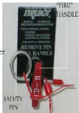
metals and fuel time to cool. Refer to the manufacturer's owner's manual for additional information.
High Water Alarm
Using a bilge float sensor this component determines a high water bilge situation and sends a signal to the dash alarm. This may indicate that a large amount of water has entered the hull or there is a leak in the engine water circulation system and the bilge pump cannot evacuate water overboard fast enough or has failed to operate. Periodically, activate the bilge pump manually to check operation.
BEFORE STARTING ENGINES
It is important that you read the engine operator's manual carefully and become completely familiar with the operation as well as required maintenance procedures on the engines and related propulsion systems.
Before starting the engines check the guidelines below:
-
Open the engine hatch and sniff for fuel smells and visually check for fuel leaks. If gasoline vapors are sensed or leaks seen be sure to determine the cause and repair the source before starting the engines. If you can not locate a fuel leak contact a marine professional immediately or your closest Regal dealer.
-
Remove any loose canvas and store in a dry location.
-
Shut and secure all hatches and doors.
-
Remove any debris from the engine water strainers before turning on the seacock handle.
-
Ensure both engine seacocks are in the "open" position. In the open position the handle is in line with the incoming hose not perpendicular to it.
-
Make sure the swim ladder is secured in its folded position and that the cover is in place.
-
Check fuel supply levels. Use the fuel "1/3" rule.
-
Turn all battery switches to the "on" position at the battery management panel.
-
Activate the VHF and listen for the latest weather conditions.
-
Activate the plotter and radar checking their functions.
-
Make sure all passengers are accounted for, seated and their life jackets are properly fitted.
-
Check for a balanced load.
-
Before disembarking make sure a person is aboard who knows how to operate the vessel and is trained in emergency procedures in case the captain would not be able to carry out his duties.
-
Inspect the engine and drive oil levels. Add specified oil as required.
-
Check engine coolant levels. Add specified coolant as required.
AFTER STARTING ENGINES
-
Allow the engines to idle for a short period and warm up. Never race a cold engine!
-
Check gauges for proper operation. Pay particular attention to volts, oil pressure and temperature display panel functions as they are key indicators of a proper performing engine. Also, check that no alarms are displayed and no warning lights are flashing.
-
Open the engine compartment and listen to each engine for unusual sounds.
-
Inspect the fuel, exhaust, and engine circulation system for leaks.
-
Visually check the entire sump (bilge) for any unusual conditions.
-
Visually check the through hull fittings located on the outside hull for the proper water output from components such as the air conditioner pump and generator.
TYPICAL ENGINE ROOM OVERVIEW
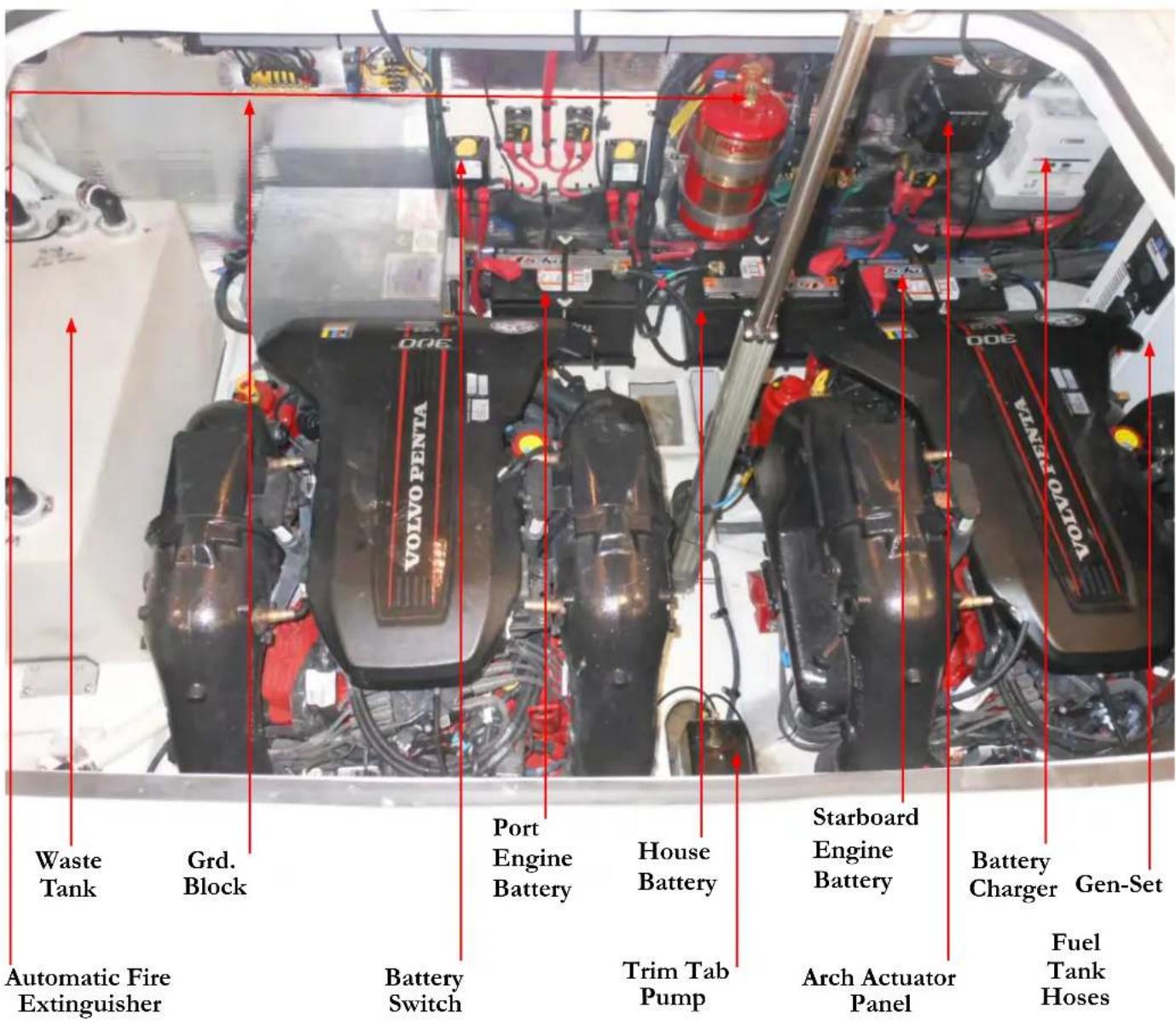
Note: Equipment shown may be optional. Components, systems and locations are subject to change at any time.
ELECTRONIC CONTROLS/STEERING
Electronic remote controls and related joysticks are available on both Volvo and MercCruiser engines as optional equipment. Also, as part of the Volvo EVC and MercCruiser DTS Axius technology electronic steering enhances both these options.
Standard engines use binnacle controls and mechanical helm steering cables along with engine power steering units.
Read your Volvo or MercCruiser operator's manual for more detailed information. The following pages offer an introduction to these units.
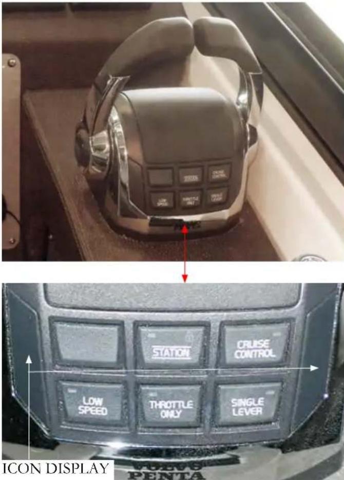
Station button- featured for multi-station boats. Since Regal cruisers feature one helm the station button lights up "green" when the control is activated This function can't be configured.
Throttle Only button- when pressed it disconnects the shift function. At this point the control lever only effects the engine speed.
Low Speed- This function reduces the low speed engine capability. Refer to the IPS operator's manual.
Cruise Control button- when pressed it permits the operator to fine tune by increasing or decreasing engine rpm with the button on the forward side of the control. Use the arrows on the button to increase or decrease engine rpm.
Other indicators- On the port and starboard sides of the control various icons are displayed including the following:
Neutral position- This symbol shows that the engine and drive are disengaged.
Warning triangle- This symbol lights up when a system fault is recognized. It will project on the side where the driveline with the problem exists.
The Volvo control offers several button options which can be added through the retail dealer who orders the needed software from Volvo.
For more detailed information refer to the Volvo IPS operator's manual or contact your closest Regal dealer.
MerCruiser- General Button Functions
MERCRIJSER DTS CONTROL SHOWN

Throttle Only- When the button throttle only button is depressed, put both throttles in neutral and push the handles forward as desired for throttle only positions.
Dock Mode- When activated the system cuts power by 50% for docking situations. Basically it provides “room for error” assisting in tight maneuvering.
Transfer- This button is used on vessels with more than 1 helm station. It is currently not being used in the Regal model line-up.
NOTICE
PRACTICE YOUR REMOTE CONTROL SHIFTING AT AN ON THE WATER ENVIRONMENT WITHOUT HEAVY BOAT TRAFFIC.
Below is a general description of the MerCruiser electronic control functions. Consult you engine operator's manual for more in-depth information.
The Axius electronic control system converts manual control movements to digital readings which tell the engines how to maneuver.
Trim button- The port handle offers power trim with 3 functions available: port engine trim, starboard engine trim, and a button that synchronizes both trim systems.
Syn- Allows the use of one control handle to throttle both engines. With both engines running over 1500 rpm's when the syn button is pressed you put the port handle in the neutral position and press the lever button. Now the port handle controls both engine throttle functions and you can put the stbd. handle in an out of the way position.
TYPICAL MERCRIJSER DTS CONTROL PAD
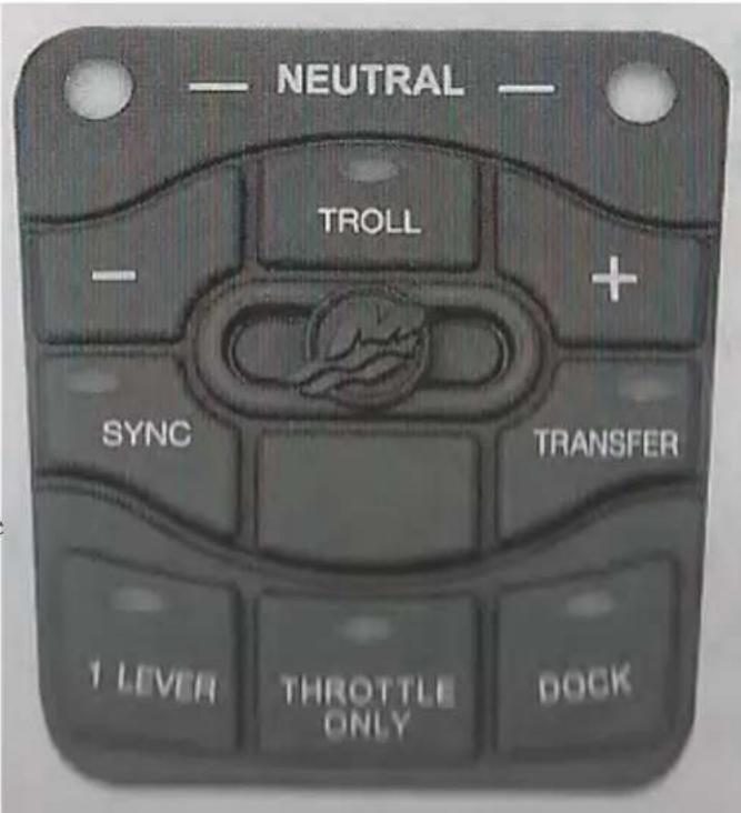
JOYSTICK CONTROL-VOLVO
Using Joystick Control Docking Mode Function
When using the joystick for docking the engine rpm scale is limited and the boat can only be steered with the joystick.
For the docking mode to be activated the engines must be running, the remote control levers must be in the neutral position, with an active helm station, and the joystick handle must be centered.
First, activate the docking mode on the joystick by depressing the "docking" button (A). You will hear an audible signal confi rming the docking function is activated along with a button lamp being energized. The joystick is now the control for docking and low speed maneuvering.
Next, to deactivate the docking mode depress the docking button on the joystick. Again, an audible signal will sound twice to confirm that the joystick docking mode is now deactivated and the docking button light will go out.
Note: If the remote controls are moved from the neutral position the docking function will deactivate.
Using Joystick Control High Mode Function
Sometimes a strong wind or current will need to be offset by engaging the high mode function at the joystick control. Once activated the engine idle will increase. This feature can be especially useful when trying to dock or maneuver in tight areas.
To use the High Mode Function;
- Activate the high mode by pressing button (B) on the joystick (see the illustration).
- You will hear an audible signal indicating the docking mode is activated and the docking lamp above the high mode button will light (see illustration).
- At this point the vessel can be maneuvered by moving the joystick fore and aft, sideways, or rotating the vessel by twisting the joystick top. See the illustration on the following page.
- Leave the high mode function by pressing button (B). An audible signal will sound twice to confirm that the high mode function is deactivated and the light will go out.
- The system is now in normal docking mode not connected to the joystick control.
NOTICE
USE THE JOYSTICK ONLY IN DOCKING SITUATIONS. USE THE STEERING WHEEL AND CONTROLS IN ALL OTHER APPLICATIONS.

Read and understand the Volvo joystick before attempting to use the component. Practice maneuvering in an open area until you become acquainted with the device.
The Volvo joystick features a DPS (dynamic positioning system) button option which can be activated through the retail dealer who can order the needed software from Volvo.
The DPS feature assists in retaining a selected position and compass heading from the vessel's GPS signal. This can be beneficial while waiting for a dock or a bridge to open or to remain over a favorite fi shing or diving location.
When employing this feature the operator must maintain helm control since legally the vessel is considered to be under way. Also, keep several boat lengths away from swimmers, other vessels and objects.
NOTICE
PRACTICE YOUR REMOTE CONTROL SHIFTING AT AN ON THE WATER ENVIRONMENT WITHOUT HEAVY BOAT TRAFFIC.
JOYSTICK FUNCTIONS
![graph TD A["FORWARD"] --> B["AFT"] B --> C["SIDEWAYS"] C --> D["DIAGONALLY"] D --> E["ROTATE"]](/content/2026/05/1030542/images/4278ab463fb86cc868b24b45fca2b101f4c01edc4e23832ee6dcc1ceed8e55cc.jpg)
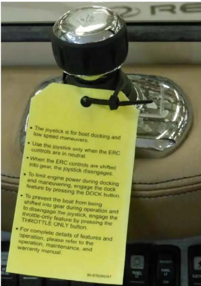
Using MerCruiser Basic Axius System-Joystick Control
Read and understand the Axius joystick before attempting to use the component. Practice maneuvering in an open area until you become acquainted with the device.
Pressure on the joystick control determines the speed of the vessel. With the DTS remote control in neutral the joystick can be activated.
It functions with 360 degree control of the vessel maneuvering forward and aft, diagonally, or side to side. Be sure to read and understand the yellow tag above.
The Axius joystick system features your ability to control low speed maneuvering power and location of the vessel with your fingertips. Allows docking of your boat in a safe and relaxed manor regardless of close quarters, cross currents, or side winds.
Need to go to starboard? Push the joystick to the right. Need to power fast to the port? Push the joystick further to the left. The Axius system uses thrust proportional to the amount of joystick movement- the more you push the joystick in one direction the more thrust is applied. This is especially useful in slow speed maneuvering/docking situations.
Simply twist the Axius joystick to turn the boat around.
Move the joystick to the right, left or at any angle to move the boat exactly where you want it.
Move the joystick toward the bow or stern of the boat to move directly forward or backward.
Note: With the Axius Premier system option additional features are available such as auto pilot and auto heading.
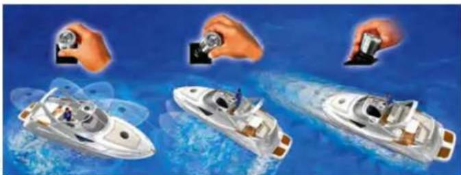
For more detailed functions read the engine operation manual.
Vessel Operation

This chapter explores select parts of running your vessel from casting off to docking and handling emergencies. We recommend further reading to enhance your information on the chapter topics. Also, become familiar with your engine owner's manual since many of the items noted here are found there in further detail.
GETTING UNDERWAY
■ Have all fluid levels been topped off?
■ Is the fuel tank full?
■ Are the propellers in good condition?
■ Is the drain plug in place (dry stored vessels)?
■ Have all passengers been briefed on all emergency procedures and seated for departure? Is the boat load balanced?
■ Is all safety equipment accounted for and easily accessible?
■ Are navigation lights and sound signals in good working condition?
Is the bilge free of water and do the bilge pumps operate?
■ Is the operator sober, alert and ready to skipper the vessel?
■ Have all passengers been fitted for the proper size life jackets?
■ Has a fl oat plan been fl led and left with a competent person?
■ Has the bilge been sniffed and the fuel system leak checked?
■ Are the appropriate sea cocks open?
■ Is all communication equipment in good operating condition?
■ Has a second person been briefed on operational, emergency, and VHF procedures should the skipper become disabled?
■ Are all gauges and electrical switches functioning properly?
■ Has weather information been gathered and analyzed?
UNDERWAY QUESTIONNAIRE
■ After casting off have all dock lines and fenders been stowed?
■ Are all passengers seated?
As skipper are you monitoring the dash gauges and chart plotter for changes?
■ As skipper are you on the lookout for changing weather?
As skipper are you checking for abnormal vibration or steering?
DISEMBARKING QUESTIONNAIRE
■ Have you removed the keys from the ignition and secured them?
■ Have all systems been checked for leaks?
■ Have the battery switches been turned to the "off" position?
■ Are all storage compartments and seacocks closed?
■ Has the fuel tank been filled enough to assist in preventing condensation?
■ Is the vessel properly tied and covered with equipment stored?
! WARNING
PRACTICE "NO SMOKING" AND EXTINGUISH ALL FLAMMABLE MATERIALS WITHIN 75 FEET OF ANY FUEL DOCK.
! WARNING
PREVENT INJURY OR DEATH FROM FIRE CAUSED BY LEAKING DIESEL FUEL. INSPECT ENTIRE FUEL SYSTEM AT LEAST ONCE A YEAR.
! WARNING
TO PREVENT INJURY OR DEATH USE ONLY GENUINE MARINE ENGINE/DRIVE REPLACEMENT PARTS
NOTICE
SINCE DIESEL IS AVAILABLE IN VARIOUS SEASONAL BLENDS, REFER TO THE ENGINE MANUFACTURER'S OPERATION MANUAL FOR ACCEPTABLE TYPES.
BEFORE FUELING
Note: To be extra safe the skipper should follow the procedures below for fueling diesel that are normally defined for petrol. Gasoline exhibits much greater flammable/explosive characteristics but diesel can ignite and burn under the right conditions.
■ Make sure a working fire extinguisher is at close expansion. hand.
■ Stop engines while fueling.
■ Disembark all passengers and crew not needed for fueling.
■ Fuel if possible during the daylight hours.
- Check to ensure nobody is smoking in the boat or near the fueling dock.
■ Close all enclosures to keep vapors from blowing aboard and settling in the bilge.
■ Tie up your boat securely at the fuel dock.
■ Identify the fuel fi ll.
■ Visually inspect all fuel system components before each filling.
DURING FUELING
- Keep the fuel nozzle in contact with the fuel fill to guard against static sparks. The fuel fill pipe is grounded through the fuel system wiring to protect against static electricity.
■ Avoid overfilling the fuel tank. Leave room for
■ Avoid spilling any fuel. Clean up any fuel accidentally spilled with a clean rag and dispose of it on shore.
AFTER FUELING
■ Close all fuel fill openings tightly.
■ Open all hatches.
■ Sniff in the lower bilge and engine compartment for diesel fumes. If fumes are detected find the cause of the diesel odor until the odor is gone. Look for any traces of fuel droplets or spillage.
Do not start the engines, smoke or run any electrical components until the fumes can no longer be detected.
STARTING & STOPPING

The following general information covers starting and stopping your engines. Read and understand all previous information on remote controls, fueling and operational procedures. Pay particular attention to all labels. Refer to the engine operation manual for in-depth propulsion system information.
Review all pre-departure information. Before starting your engines make sure all canvas is removed and stored. Start engines only in a well ventilated location to avoid diesel exhaust buildup. Make sure all battery switches are activated. Close and lock the center windshield section.

WARNING
AVOID PERSONAL INJURY OR DEATH! WHEN ENGINE IS RUNNING TRANSOM DOOR MUST BE CLOSED AND LOCKED. SWIM PLATFORM AND LADDER MUST NOT BE IN USE.

WARNING
AVOID SERIOUS INJURY OR DEATH! THE OPERATOR OF THE CRAFT MUST HAVE COMPLETE CONTROL OF THE HELM STEERING STATION WHILE THE VESSEL IS MOVING. NEVER LEAVE THE HELM STEERING STATION UNATTENDED WHILE THE VESSEL IS MOVING.
STARTING GUIDELINES
Position the remote control handles in the neutral position. Keep passengers seated and away from controls.
Note: With earlier models the Volvo EVC-D control station will be activated once the ignition key is in the "ON" position (key position l) At this point the neutral "N" icon will display a green light.
Next, turn the key to the start position (key position lll).
You will hear the starter cranking over the engine. When the engine starts release the key switch. If additional cranking attempts are needed, the key must be returned to the 0 position first.
If the engine does not start, refrain from cranking the engine over 10-12 seconds. Allow the starter and battery a chance to recover. Advance the remote control in the neutral throttle position only as recommended in the engine manual. Do not race the remote control in the neutral position.
On later EVC-D systems, turn the key to the "ON" position and then to the start position. Release the key. The starter will continue to crank until the engine starts.
With this system once the keys are engaged in the automatic start position they are disengaged if you try to turn them again to the start position.
On the newest Volvo engines a key fob system is used to start the engines. The system uses two main parts; the key panel and the key fob. Two key fobs come with dual engine installation along with a 2.5" key panel. The key panel uses lighted icons to show active ignition and start/stop positions. Theft protection is vastly improved with the E-key system.
If the starter stays engaged for more than 30 seconds the circuit is automatically cut to protect the starter from overheating. If this happens, let the starter cool for several minutes before attempting to restart the engine.
Note: With all the above systems, refer to the Volvo operator's manual for further information.
SHIFTING GUIDELINES
Before shifting into reverse or forward make sure the coast ] is clear. When shifting to either gear from neutral make sure the throttle is in the idle position. Do not pause but engage the shifter quickly into the desired gear. Allow your vessel to lose all headway before shifting into reverse or forward gear. Practice shifting! You will become more familiar with the procedure and self-confidence will build especially in tight docking situations. Most importantly, stay alert! When maneuvering into a tight slip or pier be sure to use the IPS joystick "docking" button. If the current or wind is strong use the joystick "high" button which will supply increased idling speeds.
STOPPING GUIDELINES
Before stopping the engines make sure they are in neutral and at idle speed. After an outing let the engines cool down by idling for a few minutes before turning the ignition off. Glance at the gauges one last time to monitor their readings. Never turn the engine off while in forward or reverse gear or back up in excessive speeds since water could enter the engine through the exhaust system and cause extensive damage. Above all, use common sense.
CAUTION
AVOID ENGINE DAMAGE! CHECK THE OIL GAUGE IMMEDIATELY AFTER STARTING ENGINE. IF LOW OR NO READING SHUT DOWN ENGINE IMMEDIATELY AND INVESTIGATE THE PROBLEM.
CAUTION
TO PREVENT INJURY DUE TO FALLING DO NOT OCCUPY SUNPADS WHILE VESSEL IS MOVING!
FENDERS
FENDER USAGE
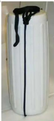
Fenders are normally made of a rubberized plastic and are usually filled with air. Most have a tting like a basketball so they can be inflated or deflated. Fenders are available in a wide range of sizes and shapes to fit both small and large vessels. Fenders are normally designated in inches. They are used for protection between piers, docks, sea walls and the vessel. They protect the topsides of the boat from rubbing against rough objects. Most fenders have attachment eyes which allow a line to be inserted vertically or horizontally. This will permit the fender to be tied off to fit individual dock and tidal situations. Be sure the fender is correct for the vessel size. The standard fenders specified for your Regal yacht are 10" in diameter and 26" long. It is a good idea to carry extra fenders but half a dozen is normally an acceptable number. Remember to store fenders on board so they can be easily accessed. The forward stairway locker stores 2 fenders. Sometimes people call fenders "bumpers" but this is not correct nautical terminology.
FENDER TYPES

Additional yacht fenders can be ordered through your Regal yacht dealer. Explain how you moor and use your vessel so your dealer can recommend the best fender type for you. We suggest the type with a fi ll plug so you can infl ate them with a hand pump like the ones used for bicycles or a 12 volt compressor (plugged into the 12 volt vessel accessory plug).
DOCK LINE BASICS

Most skippers use dock line terminology fairly loose but there is more to the basics than just bow or stern lines. There are several lines that can be secured to the bow and stern and depending on their direction and use, can be called other names. Remember that “forward” and “aft” refer to the direction that a spring line runs from the vessel, and not where it is secured on board.
BOW AND STERN LINES
There is only one true bow line. It is secured to the forward cleat and run forward along the dock to prevent the vessel from moving to the stern. The stern line leads from a rear cleat to a piling or cleat on the dock astern of the vessel. This line keeps the boat from moving ahead. For small vessels these are the only lines needed for normal wind and current conditions. If located in a tidal environment, keep slack in the lines.
BREAST LINES
These lines are attached to the bow and stern that lead to nearly right angles from the center of the vessel to the dock. They help keep larger vessels from moving away from the dock, or are pulled in to help people board the vessel. Bigger vessels may use bow or quarter breast lines.
SPRING LINES
Most boats use two spring lines although it is possible to have four. They are called the after bow spring and forward quarter spring.
Bow springs are secured at the vessel's bow area. Forward spring lines lead forward from the boat to the dock and control movement stern ward. After springs stem aft from the vessel, and stop movement ahead. Spring lines are used to prevent movement in a berth, ahead or astern. They are really useful in controlling the effects of a real active tidal surge. Spring lines are useful where fenders need to be kept in place against piles.


BOAT MOORING
Most boats can be secured to a dock using four lines. The after bow spring is crossed with the forward quarter spring and secured to individual dock cleats or pilings. This ensures longer springs and can be snugged up tighter for more efficient tidal control. Remember, if you only have one piling available, position the vessel so this point is opposite amidships. Run both spring lines to it. These lines will be shorter but still useful.
The bow and stern lines should be relatively at a 45 degree. Secure a little slack in the other dock line, then slip your angle with the dock. The stern line can be attached to the eye up through its loop and over the top of the pile. Your near-shore quarter cleat, but will work more efficiently line can be dropped through the other eye.
to the offshore quarter cleat. The longer line will allow
the boat flow with the tide with less time checking the vessel.
Note: Never use the swim platform cleats for permanent mooring cleats.
DOCK LINE SIZING
Most dock lines today are made of nylon, either of twisted rope or braided core and cover. The most often used material is nylon because of its stretching abilities absorbing shock loads. It is chafe resistant for extended life and is easier on bare hands.
The line's size varies with the vessel. Normally, a vessel in the 50' range will use 5/8" diameter nylon lines.
Dock lines need to have the strength to hold the vessel and up on the splice.
have enough density to resist chafing. They shouldn't be too heavy that they lose their shock-absorbing capabilities.
Use the right size line for the vessel since a line too large for the boat will pull hard against the vessel since it won't be forced to stretch. If the line is too small for the vessel, there is no margin for wear and chafe when under strain.
DISEMBARKING-LEAVING THE DOCK
When debarking from a dock, it is easier to release the line from a cleat or piling, from on board the boat, as soon as you leave the dock. Loop a long line around the cleat or pier and leading both ends on board you can release the line easily. Slip one end around the cleat or pile, the pull it back on board. Release the line without the eye splice, so it will run freely from around the pile without hanging
SECURING LINES
When mooring your boat, make sure the dock lines are secured at both ends. Depending on your situation you may need to loop the eye splice of the dock line around a piling. Sometimes the mooring line will lead down sharply from the piling to the deck cleat. Loop the eye splice around the piling twice to keep it from being pulled up off the pile. Pull the line through the looped eye if the mooring line is too small to go around the piling twice or too small to fit over once.
If you must drop a line over a piling that already holds another boat's line, run the eye of the line up through the first eye from below, then loop it over the pile. This will allow either line to be removed without disturbing the other. If another line is dropped over yours, simply reverse the process.
KNOTS
Knots are useful in docking, towing and other emergency situations. Learning to tie knots requires practice. As they say “Practice makes perfect”. Some of the knots used in boating are the square, bowline, anchor bend, clove hitch, figure eight and half hitch. There are several periodicals available that explain various knots and how to tie them effectively. An experienced skipper will know the basic nautical knots and will use them when on the water. Take the time to know the basic knots.
Figure 8 Knot
Tied To Cleat
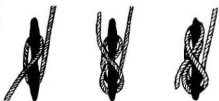
A useful knot to learn for general docking is the figure eight with one end reversed. By turning the free end of the line back under, the knot can be released without disturbing the boat. After some practice one person can secure a vessel easily to a dock or pier in a variety of weather conditions. This knot normally is used to tie the bow and stern. Then the vessel can further be fastened by tying the spring lines in the figure eight knot. Wrap it around the cleat 2 or 3 times.
DOCKING-GENERAL
As a general note docking and slow speed maneuvering can be one of those operations many skippers dread. The IPS joysick with a little practice makes you look like a pro while docking your vessel in wind, current, and tight mooring situations.
Read your engine manual to become familiar with the joystick and remote control components. It is a good idea to practice your beginning docking techniques in an open area. Remember practice makes perfect!
Helpful hints using the joystick;
-
For better control hold the joystick knob lightly almost like you would a delicate object. Push the joystick to the port or starboard, forward or aft and the rig instantaneously follows the fi ne fi nger movements on the joystick knob. Twist the knob and the boat spins on its own axis.
-
There are 2 buttons on the joystick. Use the gentler left one for most docking (Max. RPM's 1200). The right boost button is most useful in high wind/current situations (Max. RPM's 2000). This mode shows a marked increase in joystick power.
-
Remember that both engines need to be in neutral before activating the joystick buttons or it will not work.
-
To disengage the joystick press the left joystick button again or engage one of the engine controls into gear.
-
The joystick brain responds to the turns not the position of the wheel. So whatever position you have the wheel facing when you disengage the stern drive joystick that is your new straight ahead position. Most seasoned skippers would position the wheel straight before disengaging the system.
-
You do not have to worry about disengaging the joystick and shifting the control into the drive mode at too high an rpm as the EVC system prevents any shifting above 750 rpm's.
ANCHORING

Your Reg a l y a c h t features a stainless steel plow type anchor. The anchor will set quickly in a variety of bottoms because of its unique shank profile and ballasted tip. It is a high holding type anchor made from high grade manganese steel and stainless steel for maximum tensile strength. The anchor weight is 55 pound or (25) kg. Anchoring is easier with another person on board. First be certain that the line for the anchor is properly attached, to avoid losing the anchor and anchor line overboard.
For more efficiency, a 25' length of galvanized chain has been added to the rode length. The chain will stand up to the abrasion of sand, rock, or mud on the bottom much better than a nylon line. Being galvanized the chain will resist corrosion. Approximately 175' of 3 strand nylon line has been added to ensure a adequate scope in different depths and weather situations. The nylon will stretch under a heavy strain cushioning the impact of waves or wind on both the boat and the anchor.
To anchor, select an area preferably with a fl at bottom. Mud, sandy clay and fi rm stand afford the best bottoms for anchoring. Grassy bottoms often resist the anchor taking hold and end up pulling out grass and roots. Contrary to modern belief, you do not anchor while the boat is making headway, or moving forward. In fact, the bow of the boat should be brought slowly backward, while releasing the anchor until it hits the bottom. To “snub the line” means to stop its outward “pay” or movement.
Usually the length of anchor line used should be 5 t 10 times the depth of the water depending on weather conditions. This ratio is called the "scope"; the minimum scope under average conditions is 7 or 8:1. If the scope is too short the anchor's efficiency is diminished. A longer scope cushions the shock load on the entire system.
Once a scope is determined sometimes it is diffi cult to know how much line to let out to reach the desired scope especially at night. One way to mark an anchor line that will identify the amount of line is to paint wide and narrow bands from about 50' to 150' in 10' intervals. The wide bands equal 50' and each narrow band would equal 10'. Distinguish each 50' band with a different color paint. This can be done with "see in the dark" paint. Simply tape each length for the appropriate band before painting it.
After you have anchored, check your position with landmarks if possible. You need to continue to monitor these landmarks to make sure you are not drifting. Since anchoring can also be an emergency procedure, the anchor and line should be readily accessible. Check anchor locker to ensure an untangled anchor line.
Once anchored the anchor line must be secured to a strong tie such as a cleat.
Do not rely on the windlass brake to carry the anchor rode load. Use a series of full turns and half-hitches around the cleat horn to prevent any line slippage or jamming. This is important as the scope may need to be adjusted over a period of time and you need swift access to the line.
For increased holding power in windy conditions, two anchors are sometimes set. If your primary anchor drags, you can run out your secondary anchor without picking up the primary one. The important thing is to lay them out at an angle. When setting two anchors, make sure they are fastened to separate strong ties such as cleats. This is done in case you need to adjust one later so the line must be accessible.
Note: In times of high waves a buoy on the rode works as a shock absorber and allows the vessel's bow to ride the wave crests without large strains being transmitted to the set anchor. These plastic foam buoys can be purchased at boating retail outlets.
TOWING
ADMIRALTY LAW
In case you find yourself aground or in need of a tow, or should you want to tow another vessel, keep in mind that you never use deck hardware or cleats to secure lines for towing!
The Admiralty law sometimes referred to as the salvage law was founded primarily on English law fundamentals and basically says that a vessel distressed, in danger of flounder, if rendered assistance from a towing company
Deck hardware is intended for mooring and anchoring, and/or private agency, can be forced to relinquish a portion of is not designed to withstand the strain and pull of towing. the vessels' worth for the assistance received.
Rather than tie the line to your cleats on deck, it is suggested
that you tie a bridle by passing a line completely around the hull of your boat to avoid structural damage.
When towing, always stand clear of a taut line, as any type of line breaking under stress can be extremely dangerous.
The preferred line for towing is double-braided nylon, as it has sufficient elasticity to cushion shock loads. Move slowly and cautiously.

DANGER
AVOID DEATH OR SERIOUS BODILY INJURY! DO NOT USE DECK HARDWARE INCLUDING CLEATS FOR TOWING OR LIFTING PURPOSES.
NOTICE
IN THE EVENT YOUR VESSEL IS IN DISTRESS
PRIOR TO ALLOWING
ANY TOWING COMPANY
OR PRIVATE AGENCY THE RIGHT
TO PASS A LINE TO YOUR VESSEL,
BE SURE TO ESTABLISH THAT YOU
DO NOT AGREE TO ANY SALVAGE RIGHTS.
ESTABLISH WITH THE CAPTAIN
OR OPERATOR
THAT YOU WISH TO BE ASSISTED
IN A CONTRACT BASIS
AND ESTABLISH A PRICE.
OF COURSE IN CERTAIN SITUATIONS,
YOU MAY NOT HAVE THIS OPTION.
USE YOUR BEST JUDGEMENT!
EMERGENCIES
Always be ready to help others on the water if possible, but do not take any unnecessary risks. Use equipment to save a life, but do not risk a life to save equipment. Consult earlier information in this manual concerning accidents, etc. Also, read other literature concerning on the water emergencies. Be alert and prepared!
FIRE
Fire aboard a vessel can spread quickly and can cause tremendous alarm among everyone. Most fires can be prevented by keeping the bilge free from oil and debris.
Keep all equipment stowed and maintained in working order. Carry backup fire extinguishers on board. If something becomes a possible fire hazard, remove that possibility at once.
Never use water on gasoline, oil or electrical fi res. When you dump water on an electrical fi re you can be shocked since water conducts electricity.
Follow these instructions if a fi re breaks out:
- Fit everyone aboard with a life jacket. Turn off the ignition switch.
- Try to keep the fire downwind. If the fire is to the stern, head the bow toward the wind. If forward, put the stern to the wind.
- If the engine should catch fire, shut off the fuel supply. Usually there is a fuel tank access that you can crimp the fuel feed line.
- Use a hand fire extinguisher. Make sure to point it at the base of the flames. Use short bursts and sweep the extinguisher side to side. Remember: (A 4 pound extinguisher discharges in approximately 20
seconds)
These actions help prevent the fire from spreading to other parts of the boat. You can extinguish fires quickly if you act swiftly. Have a plan of action in motion in case a fire breaks out.
FIRST AID
Knowing first aid can save lives. A first aid kit and the ability to use it are important ingredients for the safety of a skippers' passengers, crew and vessel. Having confidence and competence in handling medical emergencies on board is a must for the skipper. Invest your time in a first aid course available at the American Red Cross.
CPR (BASIC LIFE SUPPORT)
If someone is seriously injured have someone call for help, while the injured person is being attended.
Check for possible danger signs; loss of breathing, unconsciousness, severe bleeding and heartbeat. If you determine the individual is not breathing or unconscious place the victim on their back on a hard surface and do the following:
- If unconscious, open the airway. Neck lift, head lift or chin head lift.
- If not breathing, begin artificial breathing. Pinch the nose. Give 4 quick breaths. If airway is blocked, try back blows, abdominal or chest thrusts and finger probe until airway is open.
- Check for pulse. Begin artificial circulation. Depress sternum. Fifteen compressions rate 80 per minute. 2 quick breaths. Continue uninterrupted until advanced medical support is available.
HYPOTHERMIA
Hypothermia is a condition where the body temperature decreases because the body can't generate enough heat to maintain its normal temperature. It can be serious and usually occurs where victims have been immersed in water (under 68 degrees) for periods of time. If you encounter a possible hypothermia victim call for help on the radio and get the person out of the water.
Symptoms are:
- Shivering that if condition is advanced may stop.
- Confusion, clumsiness or slurred speech.
- Rigid muscles.
- Semiconscious to unconscious.
Treat hypothermia by the following:
■ Remove wet clothing.
■ Monitor the victim's pulse and breathing.
■ Rapidly apply heat to the body core by using blankets, naked bodies or warm water.
■ Do not give the person any food or drink.
■ Do not warm the arms and legs. Warming of these extremities can be fatal.
Follow up immediately with medical authorities!
CALIFORNIA AIR RESOURCE BOARD (CARB) LABEL
Your Regal boat may have a star shaped label affi xed to the bow port hullside. It is located at the front of the state registration numbers. This label is part of the California Air Resource Board (Carb) SD/I rule. If your boat is operated in the state of California and/or bordering waters, this label MUST remain intact. The label shows that the engine installed as original equipment meets a currently approved California state regulatory emission level. See the example below which shows the current California ultra low 3 star label.

CARB LABEL
CALIFORNIA PROP 65
Proposition 65 relates to the state of California and is an additional requirement added to their Safe Drinking & Toxic Enforcement Act of 1986. Prop 65 basically summarized states that: “No person in the course of doing business shall knowingly discharge or release a chemical known to the state to cause cancer or reproductive toxicity into water or onto land where such chemical passes or probably will pass into any source of drinking water ....” and it goes on to say “no person in the course of doing business shall knowingly and intentionally expose any individual to a chemical known to the state to cause cancer or reproductive toxicity without first giving clear and reasonable warning to such individual .....”
For more information, contact the California Office of Environmental Health Hazard Assessment at 916-445-6900 or http://www.oehha.ca.gov/prop65.html.
! WARNING
A wide variety of components used on this vessel contain or emit chemicals known to the State of California to cause cancer and birth defects and other reproductive harm.
EXAMPLES INCLUDE:
* Engine and generator exhaust
* Engine and generator fuel, and other liquids such as coolants and oil, especially used motor oil
* Cooking fuels
*Cleaners, paints, substances used for vessel repair
* Waste materials that result from wear of vessel components
* Lead from battery terminals and from other sources such as ballast or fi shing sinkers
TO AVOID HARM:
* Keep away from engine, generator, and cooking fuel exhaust fumes
* Wash areas thoroughly with soap & water after handling the substances above
FUEL SPILLAGE
The federal water pollution control act prohibits the discharge of oil or oil waste (such as from the sump bilge pump) into or upon the navigable waters of the United States or the waters of the contiguous zone. Violators are subject to substantial civil fines and criminal sanctions. A placard is normally found inside the engine hatch area or in the sump warning of overboard discharge of oil or oily waste.
ENVIRONMENTAL AWARENESS
There are numerous vessels operating on our waterways on a daily basis. Each boat has as impact on our environment. Boat operation habits, marine sanitation, and maintenance all play a role in a delicate battle to keep the ecosystem clean. Each of us has a role in doing our part as a environmentally conscious skipper to conserve our waterways.
The National Marine Manufacturer's Association lists their top ten of Eco-Boating Practices as follows:
- Observe all regulatory agency policies regarding marine toilets.
- If equipped with a holding tank, use marina pump-out facilities.
- If used, make sure bottom paints are legal and ecosystem friendly.
- Use only biodegradable cleaning agents.
- Dispose of all garbage and liter on shore properly, not on the water.
- Don't top off fuel tanks. Leave expansion room. Clean up spills.
- Watch your wake and propeller wash.
- Make sure your engines are well tuned and maintained.
- Control your bilge water.
- When fishing, practice the “catch and release” principle.
Auxiliary Equipment Operation
AUXILIARY COMPONENTS

OVERVIEW
In addition to the main components and systems reviewed in Chapter 4 there are other auxiliary equipment components outlined here. To locate more detailed information for the auxiliary components refer to the appropriate manufacturers owner's manual found in the owner's information packet. Also, further updated information may be available on the internet by using the proper name of the component and the Goggle® search vehicle.
Note: Equipment or vendors may change during a boat's life cycle as we are constantly upgrading our product line. Regal Marine Industries, Inc. retains the right to change vendors, equipment, specifications, component location, and other technical data at any time.
Interior Equipment Component Page
| Carbon Monoxide Detector | 3 | |
| Door-Companionway | 4 | |
| Fwd. Berth- Sleeper Conversion | 4 | |
| Grey Water System | 4 | |
| Hatches | 5 | |
| Lighting-Cabin | 6 | |
| Monitor-Water/Waste | 9 | |
| Port/Starboard Windows | 10 | |
| Range/Stove | 11 | |
| Refrigerator | 12 | |
| Salon- Dinette Table | 15 | |
| Seat-Helm | 16 | |
| TV-LED Monitor Precautions | ||
| Vacuum Cleaner System | 19 |
Exterior Equipment Component Page
| Antennae | 21 | ||
| Bilge Pump/Float Switch | 22 | ||
| Door-Transom | 23 | ||
| Electronics-General | 24 | ||
| Fire Extinguisher-Automatic | 25 | ||
| Generator | 27 | ||
| Hatch-Engine | 28 | ||
| Heater-Hot Water | 29 | ||
| High Water Alarm | 30 | ||
| Markers-For Slings | 31 | ||
| In-Line Waste Filter | 32 | ||
| Overboard Discharge Pump | 32 | ||
| 18 | Power Tower | 33 | |
| Pump-Fresh Water Pressure | 35 | ||
| Satellite Radio | 36 | ||
| Shower-Transom | 37 | ||
| Spotlight | 38 | ||
| Sun Lounge-Fwd. Deck | 39 | ||
| Swim Ladder | 40 | ||
| Swim Platform | 41 | ||
| Thruster-Bow | 43 | ||
| Ultra Sun Lounge-Aft | 44 | ||
| Underwater Lighting | 45 | ||
INTERIOR EQUIPMENT
CARBON MONOXIDE DETECTORS
Carbon monoxide known as CO is indeed the silent killer. It is a by-product of combustion. CO is invisible, tasteless, odorless and is produced by all internal combustion engines, heating and cooking appliances.
The most common forms of CO on board vessels are petrol engines/generators and if applicable, propane heating and cooking devices. Note: Even though your vessels propulsion system is diesel based follow the CO precautions. Also, remember that a vessel moored next to you may be a CO poison contributor.
Never operate these devices when people are sleeping. A slight amount of CO in the human body over several hours causes headaches, nausea and symptoms close to food poisoning, motion sickness or flu. High concentrations can be fatal within minutes.
The CO detector uses a mini computer to measure and a cumulate CO levels. Using the principle of “time weighted averaging” the detector monitors CO concentrations, temperature, humidity and time to calculate COHb levels. To explain COHb, our bodies prefer to absorb CO to oxygen and COHb is the absorbed ratio stated in a percent. If the detector senses high levels of CO the alarm will sound in a few minutes. If lower levels are sensed, the detector will accumulate the data and sound an alarm when the appropriate level is reached. Read and understand the CO owner's manual in the information pouch.
To turn the CO detector system on:
-
There is a breaker switch located at the main DC panel. The CO circuitry works to its best performance when continually activated plus it accords advanced warning when entering an area high in CO.
-
When power is applied to the detector, the power indicator (top) will flash on and off, followed by the (red) lower alarm indicator flashing off and on as part of a 8-14 minute warm-up period. The green (top) power indicator will indicate a solid green when the unit has reached correct operating temperature. Never operate a cooking device with the canvas up or the cabin door completely closed to prevent CO concentration build-up
CO DETECTOR

- The test cycle should be activated frequently. Simply press the button. When it is released, the (top) power indicator will flash off and the lower indicator light will flash on. Then, the lower indicator will flash off and the upper indicator light will come back on.
The top indicator light being on solid green indicates normal operation. Refer to
the CO detectors owner's manual for an explanation of the test cycle indicators.
- When an alarm sounds take action immediately. The danger alarm indicator fl ashes red and the horn beeps 4 times, pauses and repeats the cycle. This indicates a rate of 10% COHb has been reached.
a. Operate reset/silence button.
b. Call your emergency services (911)
c. Immediately move to fresh air. Do not re-enter the vessel, until emergency personnel have arrived, aired the vessel out and the alarm is in a normal condition.
d. After following steps a-c and your alarm reactivates within a 24-hour period call a qualified technician to inspect the vessel. Note that the CO detector will clear when the CO concentration has dropped below 70 ppm.
DOOR-COMPANIONWAY-TYPICAL

Keep the cab- in door closed when the boat is mov- ing. When at mooring, the cabin entry door can be held open by sliding th door and se- curing it open with the door stop. This will prohibit the door from accidentally closing.
With the optional screen door closed and the hatch screens in place cross ventilation can be achieved along with the ability to keep insects out of the cabin.
Periodically, remove any accumulated door track debris and lubricate the tracks lightly with silicone lube to keep the door sliding freely.
GRAY WATER SYSTEM
If installed, the gray water system equipment collects all used water exiting from the shower sump pumps along with the galley and head sinks. The used water is stored in the ship's holding (waste) tank. This option is used in various locals where it is illegal to pump "gray" shower and sink water overboard. The automatic float switch pumps gray water to the holding tank.
Normally it would not require any special service unless there was blockage somewhere in the system or a hose leak developed in the system. Since more liquid in the form of gray water is being returned to the holding tank pay closer attention to the waste monitor panel. The holding (waste) tank may need to be pumped out more frequently.
FWD. BERTH-SLEEPER CONVERSION

A unique feature of the cabin forward seating is its ability to convert to a full queen berth. To convert to a berth make sure the seat cushions are clear of objects and the cushions are in place.
Locate the arrowed berth conversion switch along the starboard coaming area. Depress the forward side of the switch and the hydraulic lift will raise the seats to form the queen sized berth.
To return to the seat position simply press the aft side of the switch until the assembly assumes its original seat position. See the illustrations below.


HATCH-TYPICAL
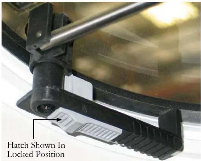
Select deck hatches feature dual lockable positions. To lock the hatch first grab the handle and turn it so it engages the side of the seal ring as shown. Push the lock mechanism to engage the handle in the locked position.
To unlock the hatch pull the handle away from the scal ring (in line with adjuster) or 90 degrees from the locked position.
To open the hatch make sure the hatch is unlocked. Then push the rod up and lock at desired angle by turning the adjuster.
A screen is provided for cross ventilation and to protect against insects. Secure the screen by turning the tabs at a 90 degree angle to the screen framework.
Note: While underway close and lock all hatches securely.

LIGHTING-GENERAL
Your vessel features various styles of lighting such as overhead, hanging locker, reading and fl orescent types. Each lighting fi xture requires specifi c bulb types and replacement procedures. Read and understand the following warning.
To change the earlier halogen overhead light bulb follow these steps:
Using a sharp object such as a small slotted screwdriver, slide it between the lens cover and the light base.
Pull down on the lens cover to access the bulb.

WARNING
AVOID SERIOUS INJURY! EARLIER HALOGEN & XENON LIGHT BULBS DEVELOP EXTREMELY HOT TEMPERATURES. NEVER REMOVE A HOT LIGHT BULB SINCE IT COULD CAUSE SKIN BURNS. WAIT FOR THE BULB TO COOL BEFORE ATTEMPTING TO REMOVE IT.
Note: The bulbs listed in the following pages can be ordered through a Regal dealer or may be available at speciality lighting or box stores. When changing the earlier halogen light bulbs never touch the bulb surface with your fingers as premature burn out can occur due to oil on the skin touching the bulb surface. Handle bulbs only from the ends.

Remove the defective bulb.
Replace the bulb with a 12 volt, #10WXM halogen type.
Line up the space in the lens cover/body with the notched area of the light base.
Push the prongs on the lens cover/body upward until they seat into the light base.

Later overhead lights use LED technology which is known for clear visibility, long service life, and energy savings. Note: These later LED lights will feel much cooler than the previous halogen type.
HANGING LOCKER LIGHTS-TYPICAL
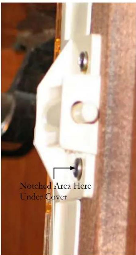
Lens Cover Removed
To change a hanging locker light bulb follow these steps:
■ Remove the lens cover from the lamp base. There is a tab on the bottom of the lens cover. Push the lens cover at this point to remove it.
■ Remove the defective bulb.
■ Replace the bulb with a 12 volt halogen bulb type # 563.
■ Reinstall the lens cover by snapping it in place.
READING LIGHTS-TYPICAL

The reading lights use a marine type bulb that allows for rough service. To change the bulb turn the fixture and grasp the old bulb and pull it straight out. Replace with the same wattage bulb. Reinstall the bulb in the lamp socket using a tissue to hold it. This procedure
will help extend the bulb service life.
FLORESCENT LIGHTS

To change a fluorescent light bulb follow these steps:
■ Remove the lens cover from the lamp base by grasping the lens on the far side. With both hands pull up on the lens to detach it. Do not force the lens as it may break.
■ Turn the bulb until both tabs on the bulb line up vertically. Pull down on the bulb to release it from the lamp body at both ends.
■ Replace the bulb with a Thin Lite Cool White #F8T5-CW-HG.
MONITOR-WATER/WASTE

To read either the fresh water or waste water monitor panel the breaker on the main DC panel must be activated.
The monitor is normally located inside the ship's AC/DC cabinet or may be located behind the starboard picture window on a trim panel.
The fresh water monitor displays the amount of potable water in the system. There are sensors located in the water tank that send a signal to the display panel when activated. Press the top portion of the toggle switch and read the gauge display.
The waste portion of the display shows the amount of waste water in the holding tank. There are sensors located in the waste tank that send a signal to the display panel when activated. Press the bottom portion of the toggle switch and read the gauge display.
This portion of the system needs to be monitored periodically to prevent the system from being over full which could cause equipment damage and/or a possible leak in the vessel.
If the waste system is determined to be full it can be emptied by connecting a marina pump-out hose to the waste fitting located on the deck. The pump out device will actually remove the waste much like a vacuum cleaner. This is the easiest way to eliminate the vessel's waste and be environmentally friendly while performing the task.
An alternative method which can be used in International waters only is to pump the waste overboard using the waste seacock.
Notice the key switch portion of the monitor. The key switch controls an overboard discharge pump (macerator) which grinds up the waste and sends it through the hull bottom. Make sure the waste seacock is open and you are legal to pump overboard. Turn the macerator breaker on and then energize the monitor panel key switch by turning it to the “on” position and holding it while you press the red button to activate the pump.
Be sure to turn the seacock off and secure it with a tie wrap after the pump-out cycle is completed as you can be fi ned if authorities fi nd the seacock in an unlocked position.
PORT/STBD WINDOWS

Port and starboard windows provide natural cabin lighting. The windows are tinted, safety glass components. They are trimmed with curtains. Windows are installed with an adhesive that is flexible and still provides an encapsulated product with waterproof protection. Do not use ammonia products on the windows. Other less chemically harsh cleaning products are available.
RANGE/STOVE-TYPICAL
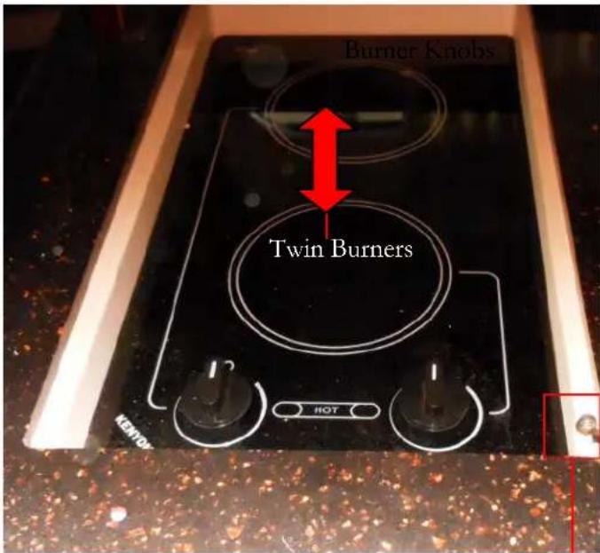
RANGE TOP CUT-OUT SWITCH
A cut-out switch shuts the power "off" to the stove burners should a cooking fire develop. When the stove cover is installed over the stove the burner power is then interrupted. At that point the stove breaker on the main AC panel should be turned to the "off" position.
Always have the correct type portable fire extinguisher ready when cooking aboard the vessel.
Note: Stove cut-out switch type and location may vary. Refer to the stove operation manual in your owner's information packet for more information.
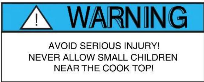

REFRIGERATOR-TYPICAL
OVERVIEW

Your refrigerator is designed to operate in the tough marine environment. It can withstand a heel angle up to 30 degrees for a short time which makes it very adaptable for marine use. A few tips on the refrigerator:

Some refrigerators and icemakers open by simply pushing the latch down and then pulling the door open. When you close the door the handle automatically will assume the closed position.
- The refrigerator uses AC/DC current switching automatically as needed as it is dual voltage.. Turn on the breaker at the ship's AC/DC service panel before activating the refrigerator.
- Unnecessary opening of the refrigerator door will increase power consumption.
- Keep the inside of the unit clean and dry.
- Remove any water that may collect on the shelf under the freezer compartment.
- When leaving the vessel for extended periods of time turn the breaker off at the ship's service panel. Remove any food from the unit. Prop the door open slightly before leaving the vessel. This helps air out the refrigerator.
- Note: The unit will keep food cold 5-6 hours without any DC power providing the food is chilled already.
- It is important that the refrigerator compressor/condenser be well ventilated so cooler air can enter from the bottom and warm air can exit the top of the unit. Never block any of the ventilation grilles.
TEMPERATURE SETTING-TYPICAL
Your refrigerator is equipped with a manually controlled infi nitely-variable thermostat.
Turn the thermostat clockwise to lower the temperature and counterclockwise to raise the temperature and to activate the on-off switch. A slight spring resistance is noticeable at the on-off switch.
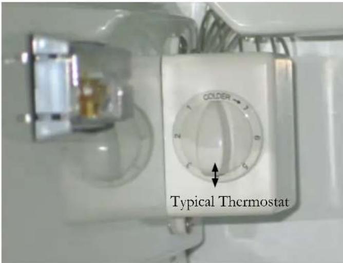
DEFROSTING
The refrigerator requires defrosting when the frost layer is around 1/8".
To defrost do the following:
- Turn the thermostat off.
- Store the food and beverages from the refrigerator in an iced down cooler.
- Do not use sharp metal objects to remove the accumulated ice. Let the refrigerator deice under normal cabin temperatures.
- Restart the refrigerator after it is completely defrosted. Be sure to clean and dry the unit.
- Empty the drip tray below the freezer compartment as often as needed in the defrosting cycle.
Normal Refrigerator Operating Sounds
Your refrigerator/icemaker combo features rigid foam insulated cabinets to provide high thermal efficiency and maximum sound reduction for its internal working components. In spite of this, the unit still may make some unfamiliar sounds.
Normal operating sounds may be more noticeable because of the unit's environment. Hard surfaces such as fi berglass floors have a tendency to reflect normal appliance operating noises.
Common refrigeration components, and a brief description of the normal operating sounds they make, are listed below.
Note: Your unit may not contain all of the components listed.
Compressor- The compressor makes a humming or pulsing sound during normal operation.
Evaporator- Refrigerant flowing through this unit may sound like boiling water.
Condenser Fan- May hear air moving through it.
Water Valve- At each cycle, a buzzing is heard.
Periods Of Non-Use
During extended periods of non-use take the following precautions.
- Turn off the icemaker breaker at the ship's AC distribution panel.
- Turn the unit to the "OFF" position at the power valve.
- Raise the bin arm to turn the icemaker off.
- Empty the refrigerator of all items. Clean the interior of the unit with a mild non-abrasive detergent and warm water solution applied with a soft sponge or soft cloth. Rinse with warm water and a soft sponge. For rust spots use Bon-Ami® or Barkeepers Friend Cleanser®
- Prop the door open. The unit will manually defrost.
SALON TABLE-TYPICAL


SALON-DINETTE TABLE SET-UP
The salon dinette table is located to provide easy access for dining needs. It is hinged to accommodate additional personnel. To use the table:
-
Unsnap the strap holding the table behind the salon sofa center backrest. Pull out the table. See illustration A.
-
For ease of installation set the table on the sofa with the table support facing up.
-
Locate the table leg. Normally it is stored in the center floor hatch opposite the salon sofa.
-
Install the table leg in the angled table receiver on the sofa riser surface. Pull the spring latch pin and hold until the leg bottoms out. Release the pin to lock the table leg. See illustration B.
-
Install the table onto the top table support until it bottoms out. Flip the hinges back to provide larger dining surface. See illustration B.
SEAT-HELM (TYPICAL)

Flip Front Cushion Up For Increased Standing Room
The helm seat features a leaning post to gain extra height or additional standing room at the helm when maneuvering in close quarters. To add seat height using the leaning bolster lift the front of the helm seat upward. This permits the leaning bolster to rotate upward until fully extended. See the illustration.
SOFA-CONVERSION TO SLEEPER
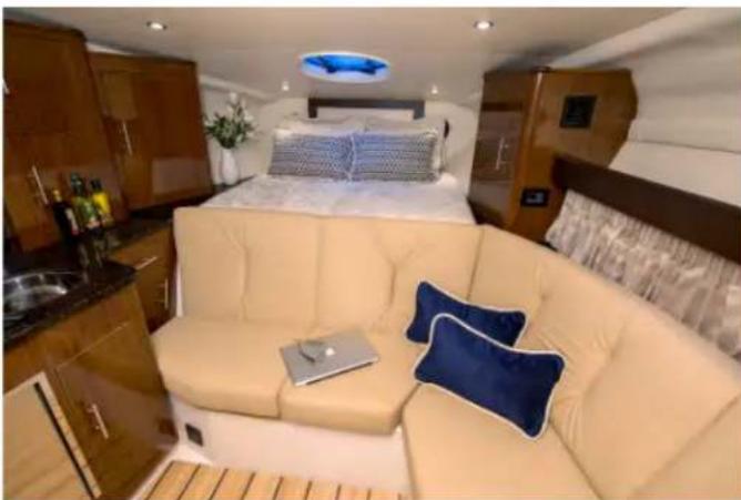
The salon sofa can serve a dual purpose as a sleeping berth. To make up the berth do the following:
- Remove all the starboard side sofa cushions (not the backrests). See the illustration below.

- Next pull up all the berth legs. Do not force the legs. There is a round leg release pin at the base of each leg that must be pushed in to release each leg from the locked position. Hold the pin in with your finger and pull the leg slowly until it passes without catching. Now the leg can be positioned vertically. See the illustrations.
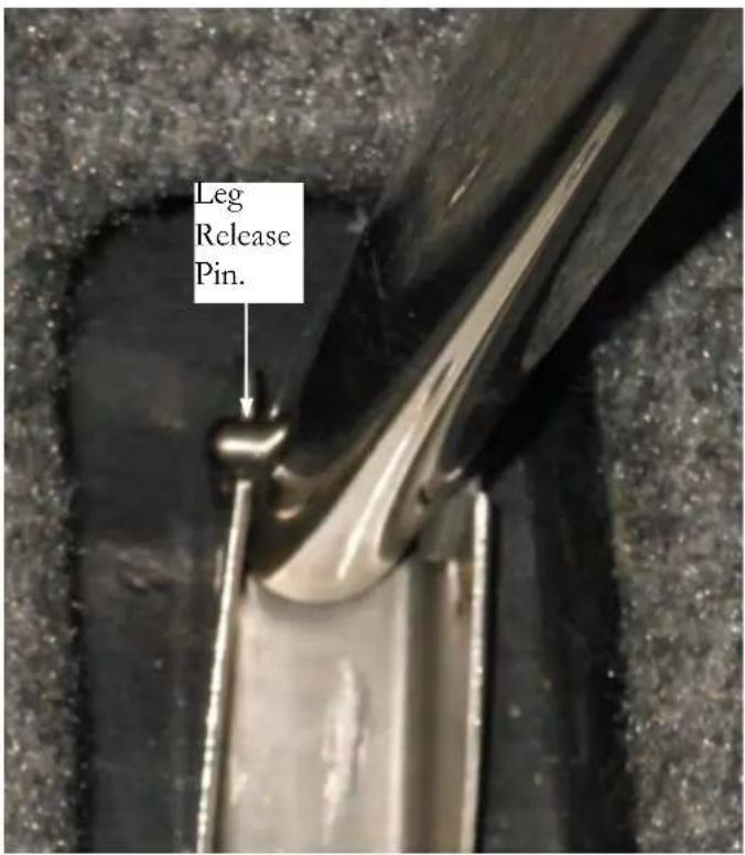

- Insert each of the sofa cushions in place. The conversion is now complete.

- Rotate each section over. This forms extra berth space. Make sure all legs are setting fl at on the salon floor.
TV (LED) MONITOR PRECAUTIONS
The following safety information applies to all LED fl at screen television monitors. Refer to the antenna switch information in Chapter 4 for the proper connection depending where the vessel is moored.
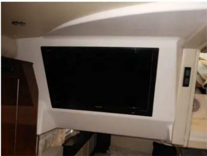
SAFETY INSTRUCTIONS

CAUTION
RISK OF EQUIPMENT DAMAGE! IN FREEZING CLIMATES REMOVE THE TELEVISION SET FROM THE VESSEL.
NOTICE
WHEN LEFT FOR EXTENDED PERIODS TURN THE TELEVISION BREAKER TO THE OFF POSITION TO HELP PREVENT POWER SURGES OR LIGHTNING DAMAGE.
NOTICE
IF TV FEELS COLD TO THE TOUCH THERE MAY BE A SMALL FLICKER WHEN IT IS ACTIVATED. THIS IS NORMAL.
NOTICE
THE FLUORESCENT LAMP USED IN THIS TELEVISION CONTAINS A SMALL AMOUNT OF MERCURY. DISPOSE OF THIS PRODUCT IN AN ENVIRONMENTAL FRIENDLY MANNER USING LOCAL GUIDELINES.

CAUTION
RISK OF ELECTRICAL SHOCK! DO NOT REMOVE COVER AT TELEVISION REAR. NO USER-SERVICEABLE PARTS INSIDE. REFER SERVICING TO QUALIFIED PERSONNEL ONLY.
VACUUM CLEANER SYSTEM-TYPICAL
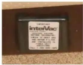
The vacuum system is located in the salon at the port forward berth bulkhead. Included with the vacuum is a netted bag of hoses and various vacuum attachments.
SAFETY WARNINGS
- This is a dry vacuum system. Do not use on wet surfaces.
- Never operate the vacuum without filters and bags in place.
- Use careful monitoring when children are around. Do not let the vacuum cleaner be used as a toy.
-
Do not try to repair the vacuum as the unit is sealed. Return the unit to InterVac or an authorized repair center for proper repairs.
-
Use only as described in this manual. Use only factory attachments and bags.
-
Do not use with any blocked openings. When the secondary filter becomes dirty, rinse in warm water or replace the filter. Filters must be completely dry before using.
-
Never drop or put any object into any opening.
-
Turn off the accessory breaker at the ship's C panel to deactivate the vacuum cleaner.
-
Keep all body parts and clothing away from all moving parts.
-
Do not pick up anything that is burning or smoking such as cigarettes, matches, hot ashes or sharp objects. Do not use without dust bag or filters in place.
-
Do not attempt to operate the unit with a wet hose.
- Do not store objects close to the vacuum unit.
- Do not pick up fl ammable or combustible liquids such as gasoline, or use in areas where they might be present such as the bilge.
- Do not step on the hose, nozzles or pull hard on the hose.
OPERATION
- To operate the vacuum, the accessory breaker at the main ship's main AC panel must be turned to the "ON" position.
- Lift the inlet cover on the vacuum unit.
- Insert the hose cuff (one with the metal band) with a slight twist and the vacuum cleaner should start.
- To remove, turn hose in either direction while pulling the hose toward you and the vacuum cleaner will stop.

Note:
If the motor stops the thermal protector on the unit will reset automatically after about 1/2 hour. This is normal for the vacuum cleaner.

Insert Hose Cuff Here
If The Motor Stops Suddenly:
-
The most common cause is a clogged hose. Try to unclog the hose with a long object or by shaking the hose until the debris falls out.
-
The bag is overfilled and fine dust has clogged the bag.
-
The vacuum cleaning tools are clogged.
-
The motor (exhaust) filter is dirty and should be cleaned or replaced.
-
While the vacuum cleaner is being used keep the cushion up to provide additional air to the unit. This will help the unit from shutting down.

Replacing Exhaust Filter
EXTERIOR EQUIPMENT
ANTENNAE
The electronics installed on your boat are NEMA 2000
compatible which permits system components to share information with other marine-network compatible devices.
Refer to your GPS/plotter owner's manual for further information.
Be aware of the vessel's bridge clearance specifications to
The GPS/plotter antenna includes a built-in position fi xingavoid equipment/vessel damage due to impacting a bridge receiver. The GPS plotter features a filter that compensates structure since a great portion of the antenna/receiving
for the rolling motion of your boat for clearer course and speed information. The antenna is protected by a plotter breakers.
The antenna receiver is located under the forward deck rope locker. Plexius is used as the attaching compound.
equipment is mounted on the hard top. Remember that the masthead light on the hardtop can be lowered if needed.
The VHF radio uses a whip style fi berglass antenna which is “trimmed” to provide the best output and reception.
The TV antenna mounted on the hard top is shaped liked a saucer.
For further information on antennas refer to each vendor's owners manual.
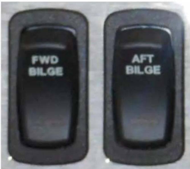
Illustration shows a typical bilge pump monitor panel helm mounted.
Your Regal boat features bilge pumps and fl oat switches in the sump (bilge) and salon (selected models). They are operated through the helm switches. There are separate switches marked forward and aft bilge pumps.
In the “off” position both switches are connected into the automatic float switch. In this “auto” position if the boat takes on water, the bilge pumps will activate and pump excess water overboard. The switch will light up when activated.
Periodically check the grates for debris and spray the units down with water. Make sure a steady stream of water exits the through hull ft tting indicating the entire output hose system from the bilge pump itself is debris free.
Monitor your helm bilge pump switch lights periodically during your cruise. If one of the lights is on that means that bilge pump circuit is energied. Stop the vessel and find the cause of the problem.
DOOR-TRANSOM-TYPICAL

To open the transom door (gate style) pull_up on the framework until the door hinge releases and swivels to an open detented position.
To close the door pull-up on the framework until the door hinge releases and swivels to a closed detented position.
WARNING
PREVENT SERIOUS INJURY OR DEATH FROM FALLING OVERBOARD! KEEP THE TRANSOM GATE (DOOR) IN THE LOCKED POSITION AT ALL TIMES.
ELECTRONICS-GENERAL

Your boat features several electronic components maked for compatibility. Manuals for each of the electronic components should be referenced for specific detailed operations. These manuals are part of the owner's information packet.
Going through each piece of electronics while at the helm with the manual will greatly decrease the learning curve time. Select electronic components are mounted on the aluminum power tower including optional radar, VHF antenna and television antenna.
Note: As an integral part of upgrading our product line Regal reserves the right to change specifications, components, locations, and suppliers at any time.
FIRE EXTINGUISHER- AUTOMATIC
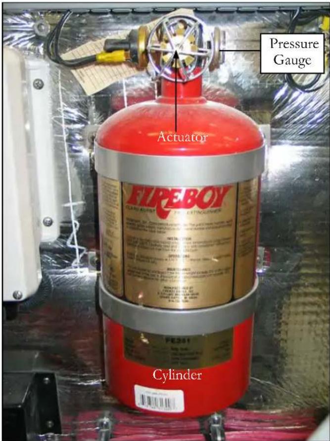
OVERVIEW
The Fireboy automatic fi re extinguishing system is located in the bilge at the forward engine bulkhead. See the illustration. The system uses a environmentally friendly agent FE-241 which has been approved by the EPA to replace the old Halon agent. This system is formulated only for use in the engine space or bilge of your vessel. FE-241 is to be used with gasoline fuel systems only since the agent will not “stall” diesel engines. This could cause a fi re to re-fl ash.
OPERATION-AUTOMATIC
Fireboy systems are not nor are they intended to be explosion suppression devices. Boat owner's still need to take normal precautions for checking fumes and using blowers.
Read the information in chapter 4 regarding the dash installed portion of the fi re extinguisher system. When the system actuation starts you may hear a loud sound simiar to that of small arms fi re, followed by a rushing air sound. The system will show actuation whenever the ignition key is ON and the indicator light is OFF. The actual actuation time when a fi re occurs is dependent on the severity of the fi re.
When the automatic fi re extinguisher activates IMMEDIATELY SHUT DOWN ALL ENGINES, POWERED VENTILATION (BLOWER), ELECTRICAL SYSTEMS AND EXTINGUISH ALL SMOKING MATERIALS. DO NOT OPEN THE ENGINE COMPARTMENT IMMEDIATELY!
Allow the agent to “soak” the compartment for a period of time and wait for hot metals and any fuels to cool before inspecting for the fi re cause. Premature opening of the engine compartment allows an in-rushing of oxygen and could result in a fl ash-back. When the engine compartment is opened have approved portable fi re extinguishers ready to use.
OPERATION-MANUAL
If a fire has started in the engine compartment where the Fireboy is located, DO NOT WAIT FOR AUTOMATIC ACTIVATION. Release the system manually. Close any opened hatches leading to the engine compartment, shut down all forced ventilation devices, engines, generators and electrical components. Remove the safety pin from the "Fire" T-handle, and pull T-handle firmly and release. A loud "rushing" or air" sound will be heard. Complete discharge will take several seconds. DO NOT OPEN THE COMPARTMENT IMMEDIATELY! Keep the compartment closed for a period of time sufficient to allow the agent to soak all areas of the protected space. This allows hot metals to cool.
Premature opening of the compartment could cause a re-fl ash. When opening the engine compartment for inspection have hand held portable extinguishers ready.
Inspect the pressure gauge and system before and after each outing. Refer to the maintenance chapter for caring for your fire extinguisher system.
The illustration opposite shows the actuator not discharged at the top and one which has been discharged at the bottom. Manual pull is located starboard of the helm seat.

Typical Portable Fire
Extinguisher


Portable fire extinguishers may be found in various cabin and cockpit lockers. On select vessels a label may be present on the exterior cabinet doors identifying portable fire extinguisher locations. Know the location of portable fire extinguishers and perform periodic inspections.
ACTUATOR
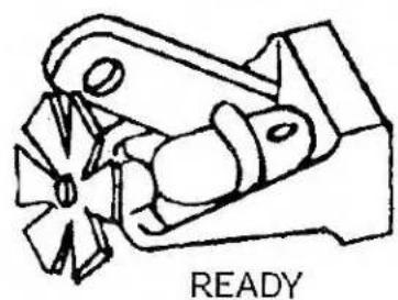
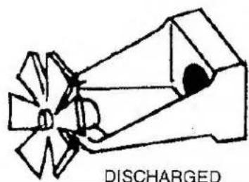
! WARNING
AVOID SERIOUS INJURY OR DEATH! DO NOT BREATH FUMES OR VAPORS CAUSED BY A FIRE AS THEY ARE HAZARDOUS AND TOXIC.
! WARNING
AVOID SERIOUS INJURY OR DEATH! ACCIDENTAL DISCHARGE COULD OCCUR DURING HANDLING, INSPECTION, OR WORKING IN THE ENGINE COMPARTMENT. WEAR EYE PROTECTION AT ALL TIMES!
GENERATOR-TYPICAL
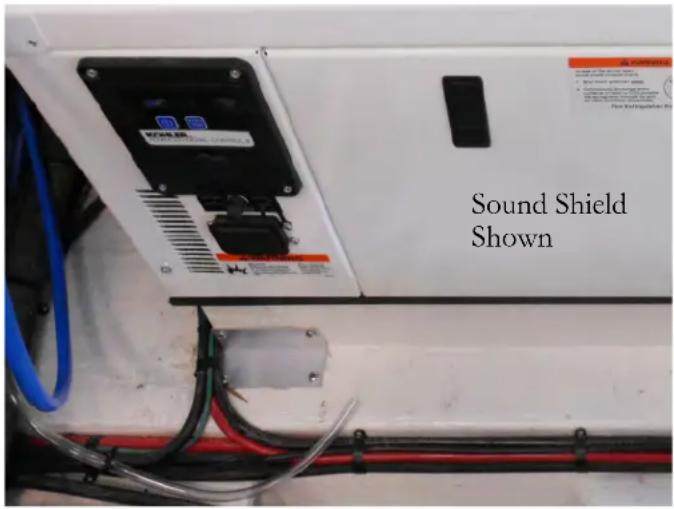
OVERVIEW
As optional equipment a gasoline or diesel generator is available on your boat depending on engine option chosen.
Current generators are more powerful yet more compact in size. They run at a slower rpm for longer life. Today domestic gas generators are rated at 5 kw (120-240 volts, 60 hertz) and diesel units rated at 6 kw (240 volts, 50 hertz). Both meet current EPA, CARB and CE emission requirements.
Detailed maintenance information can be found in the generator operating manual.
For general generator information see chapter 4 of this manual.
OPERATION
Perform the following inspections and checks before each startup, as designated, and at regular intervals as noted in the service schedule.
- Air Inlets- Check for clean and unclogged air inlets.
- Air Shrouding- Ensure the sound shield enclosure is securely fastened and positioned correctly.
- Battery- Check for proper electrolyte level. Make sure all battery connections are secure.
-
Coolant Level- Check the reservoir for proper levels.
-
Exhaust System- Check for exhaust leaks and blockages. Check the silencer and piping condition and check for tight exhaust component connections.
Inspect the exhaust parts (exhaust manifold, catalyst, exhaust hose, hose clamps, silencer and outlet fl apper) for cracks, leaks and corrosion.
Check hoses for cracks, softness, dents, or leaks. Replace as necessary.
Check for corroded or broken metal parts. Replace as necessary.
Check for loose, missing or corroded hose clamps. Replace or tighten the hose clamps and hangers as needed.
Check that the exhaust outlet is unobstructed.
Visually inspect for exhaust leaks (blow-by). Check for carbon or soot residue on exhaust parts which indicate an exhaust leak. Seal leaks as needed.
HATCH-ENGINE

The engine hatch provides easy access for periodic bilge and equipment inspections. The engine compartment (bilge) lights can be accessed at the aft port exterior lighting panel.
The engine hatch lift switch is also found on this panel. Since the hatch is electric and forward facing it is easiest to access the engine compartment from the aft to check engines, drive units and generator fluids.
The engine hatch uses a single heavy duty electric-hydraulic ram to operate up and down. Should the need arise there is a top pin which can be pulled to permit the hatch to be lifted manually in case of emergencies.
Note: Manually lifting the engine hatch requires additional manpower and the proper blocking to hold the hatch up. Do not attempt this procedure alone.

Typical Hatch
HEATER-HOT WATER
The hot water heater features a 6 gallon capacity and has recirculating ability to keep water warm during cruising. This is accomplished by a set of hoses connected between the hot water tank and the circulating engine water pump. Engine coolant runs through a heat exchanger which keeps the tank water warm when the engines are running. To initially fill the hot water heater, ensure the boat's fresh water tank is full. When the tank is full water will be seen at the deck vent. At the DC side of the main ship's AC/DC panel, turn the fresh water pump to the "on" position.
Make sure the water heater is full of water by opening a hot water faucet until a steady stream flows out. With the generator running or the shore power connected, switch on the hot water heater at the AC side of the ship's service panel. The heating element will now begin to heat the hot water tank.
Should the hot water heater reset button need to be activated turn off the hot water breaker at the AC side of the main control panel. Then remove the panel cover to expose the reset button. Press the red reset button. On newer models there is a round access port on the rear panel to reach and reset the breaker.
Should the need arise there is a drain valve located at the rear of the heater. Always turn the hot water breaker to the "off" position before opening the drain valve. Make sure the water is cold before attempting to open the valve. The valve runs through the shower sump pump and then overboard. Never try to adjust the thermostat or open the drain valve before turning off the AC breaker. Contact a marine professional for further information.
! CAUTION
TO AVOID POSSIBLE BODILY INJURY DUE TO ELECTRICAL SHOCK DO NOT TRY TO OPEN UP THE HOT WATER TANK COMPONENTS WHILE THE AC POWER IS ACTIVATED. TURN HOT WATER BREAKER OFF AT THE MAIN AC PANEL.

HOT WATER HEATER
! CAUTION
TO AVOID POSSIBLE BODILY INJURY DUE TO HOT WATER, BE SURE TO CHECK THE WATER TEMPERATURE BEFORE USING IT. THIS IS ESPECIALLY TRUE AFTER CRUISING WHEN THE WATER HAS BEEN TRAVELING THROUGH THE HEAT EXCHANGER HOSES.
NOTICE
TO AVOID EQUIPMENT DAMAGE DO NOT TURN ON THE HOT WATER BREAKER WITHOUT THE WATER HEATER BEING FULL. DAMAGE TO THE HEATER ELEMENT WILL OCCUR.
Note that the hot water heater utilizes a safety device called a T & P valve (See the illustration on previous page). Just as a home unit the valve provides relief should the hot water heater overheats. In an emergency the valve will open and hot water will exit into the bilge.
This situation will cause the bilge pump system to operate until the water supply is disconnected.
As a safety precaution always disconnect the hose from the marina water supply to the water dockside inlet valve on the boat when leaving the vessel for extended periods.
On select newer models there may be a piping connected to a thru-hull from the T & P valve on the hot water heater. In this case a blown relief valve will exit water overboard verses the bilge.
HIGH WATER ALARM-BILGE

The high-water alarm warns the skipper of a possible emergency in the bilge area. There is an automatic float switch installed in the center bilge. If the water rises over a predetermined level the bilge switch sends a signal to the helm mounted alarm. This sump float switch normally is elevated from the position of the automatic bilge pump switches.
If the alarm sounds bring the vessel back to an idled position in neutral and turn off the engines. Open the engine hatch and find the cause of the problem.
Possible causes are:
- Engine or generator hose leak.
- Mufflers or exhaust hose leak.
- Hull leak due to striking an object.
- Water or waste tank leak.
- Plumbing feed hose leak.
- Seacock leak.
- Heat exchanger leak.
-
Transducer or underwater light leak.
-
Water heater tank or heat exchanger hose leak.

Helm High Water Alarm
MARKERS-FOR SLINGS-TYPICAL
Sling markers are located on the forward and aft deck near the rub rail. These markers provide a safe location to locate straps to lift the boat. Failure to use marked sling marker locations could cause damage to the boat structure. When lifting the vessel close all doors, hatches and portlights. Make sure the spreader bars are adjustable enough to be wider than the sling beam area. This will allow the slings to hold the weight of the boat properly without forcing the boat structure inward. Make sure there is no pressure on the rub rail or swim platform wings. Always use a fl at wide belt-style straps as they distribute and hold the boat weight in a more supported fashion. Do not use the cable-style straps since they may cause hull or rub rail damage. See the notice below and the information in the technical drawing section.
NOTICE
BOAT OWNER-LIFT OPERATOR
Before lifting boat place a fendor or block between strap and hull just under the swim platform side wing (Both port and starboard) to relieve strap pressure on wing when lifting boat. When fender or blocking is positioned correctly strap will not put pressure on side wing when full weight is applied.
FAILURE TO FOLLOW THE ABOVE INSTRUCTIONS MAY CAUSE FIBERGLASS DAMAGE WHICH IS NOT COVERED UNDER THE REGAL LIMITED WARRANTY.
REFER TO THE DRAWING IN THE TECHNICAL SECTION FOR FURTHER INFORMATION ON BLOCKING.
NOTICE
AS A SAFETY PRECAUTION, WHEN THE BOAT IS LIFTED, TIE A LINE BETWEEN BOTH STRAPS TO PREVENT THE STRAPS FROM MOVING FORWARD OR AFT.
NOTICE
TO AVOID POSSIBLE FIBERGLASS DAMAGE, SET VESSEL FOR EXTENDED STORAGE ON A FACTORY APPROVED AND ADJUSTED STEEL CRADLE. NEVER USE BLOCKING TO SUPPORT THE VESSEL'S HULL BOTTOM.
TYPICAL AFT SECTION

TYPICAL FORWARD SECTION

OVERBOARD DISCHARGE PUMP (MACERATOR) TYPICAL
The overboard discharge pump (macerator)) can be used to pump out the holding tank in international waters. When the monitor panel key is energized to the full start position, the macerator engages to pump the tank waste overboard. Again, make sure it is legal to pump the waste overboard before you start the operation. Also, open the waste seacock located in the sump. The pump can be disconnected from the 2 union fittings that hold it for maintenance purposes. The pump is rated for 40 minutes continuous operation. Do not flush paper or feminine hygiene products into the waste system. Keep toilet tissue usage to a minimum. Do not use bleach or toilet cleaners in the waste system. Use only marine approved products. Rinse and flush the holding tank after each pump out. This will dilute any residual waste, and help prevent blockage and reduce odors.
IN-LINE WASTE VENT FILTER
Located in the bilge near the through hull fi tting is a long cartridge style fi lter installed in-line at the waste tank vent hose. This fi lter removes waste odor from the system while still permitting methane fumes to escape via the hull side.
The waste fi lter is not seviceable. The manufacturer recommends that it be replaced each year. See the systems chapter for additional information. Note that there are union connectors on each end of the fi lter to aid in removal.

FRESH WATER & WASTE MONITOR WITH OVERBOARD DISCHARGE


TYPICAL OVERBOARD DISCHARGE PUMP
The impeller grinds up the waste as it passes through the macerator. On the macerator shown above the system is protected by a 10 amp breaker located at the salon main DC distribution panel.
POWER TOWER-TYPICAL
As part of the innovative design the power tower hinges forward for tight overhead clearances such as bridges and restricted storage situations.
The power tower features an aluminum framework and a multi-layered finishing process along with the ability to anchor
major electronic equipment such as radar domes and various antennae.

TYPICAL POWER TOWER- SUNSHADES IN CRUISE POSITION
The power tower can be hinged forward for clearance purposes. Use the switch marked “arch” found on the stdd. switch panel to energize the power tower. It connects to a lift actuator motor and a set of hydraulic rams that raise or lower the power tower through the switch.
If towing vessel as part of a wide-load permit make sure arch is completely up. DO NOT TRAVEL OVER THE ROAD WITH THE ARCH IN THE FORWARD POSITION.
Make sure the opeartor and all aboard read and understand the above warning.
Before energizing the arch switch explain to all passengers that they maintain a safe distance from the tower hinge mechanisms located at the base of the power tower on the deck. As the operator energizes the switch to hinge the tower forward visually monitor the port and starboard deck to ensure all passengers are clear of the hinge mechanism. This same procedure applies for lowering the mechanism to the cruise position.

TYPICAL POWER TOWER IN FWD. POSITION


TYPICAL POWER TOWER SHOWN IN FULL FWD. TILTED POSITION
NOTICE
Remember that the width (beam) of this vessel is normally too wide for highway towing. Check your state laws and regulations before attempting to tow this vessel. Special permits and equipment may be needed.
For highway towing the power tower shall be in the complete forward position and all canvas shall be in their dedicated boots. All attached canvas bow hardware shall be checked for tightness before and after towing. Cockpit carpet shall be rolled up and stored in a dedicated cockpit locker.
Located at the starboard fi rewall bulkhead (bow end of bilge) is the power tower actuator control box. The purpose of this device is to provide overload protection for the port and starboard actuators that move the power tower forward and aft (see the illustration).
In addition, the control breaker protects the up and down wiring circuit to the dash for the power tower circuit.
If a breaker "pops" be sure to determine the cause of the malfunction before resetting the device.
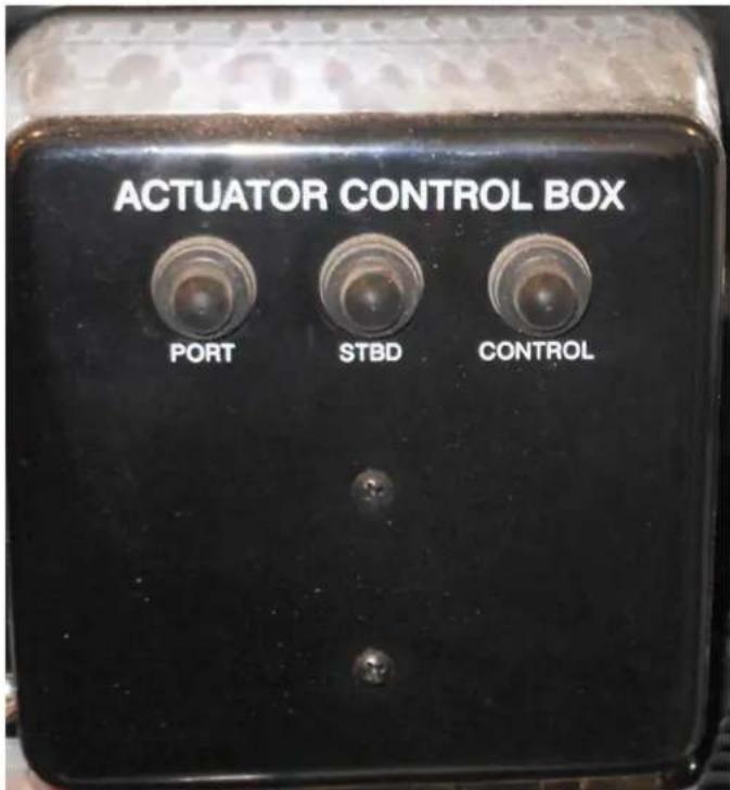
PRESSURE PUMP-FRESH WATER
Your vessel features a variable speed fresh water pressure pump. The variable speed allows for additional water flow at peak times such as using the forward and aft showers at one time. It is important not to operate the pump unless there is water in the fresh water tank. The pump is controlled by a breaker on the main DC control panel. Energizing the switch allows the pump to build the water pressure in the distribution lines to 35 psi's.
When the pump reaches a level of 35 psi the pump should automatically shut off. If the system drops below a certain pressure then the variable speed pump will restart. If the pump cycles on and off with no water being used, a leak in the water system is likely.
Periodically remove the water inlet filter and clean it. Additional filters can be ordered through your Regal yacht dealer or marine outlets.
Be sure to turn the fresh water pump at the main salon DC panel off before performing any type of maintenance.
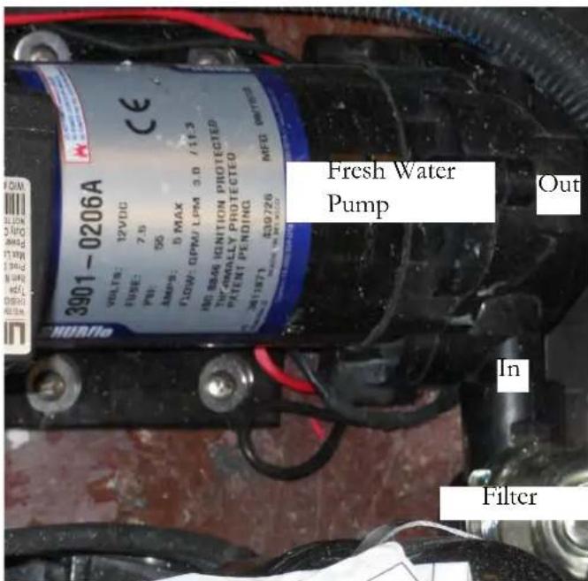
TYPICAL FRESH WATER PUMP
SATELLITE RADIO
This option is currently available on all Regal models. Sirius satellite radio features over 120 channels of music entertainment completely commercial-free along with sports and news channels. Sirius emphasizes the music and entertainment you want. Channels use the most updated digital flitering available for the clearest sound. Sirius uses three satellites flying over the United States for coast to coast coverage with high elevation angles. The result is a clearer line of sight and less signal blocking.
The system consists of the stereo receiver (sometimes called the head unit), radio tuner and antenna. With these components and an active account initialized by the customer on delivery your Sirius system should be ready to operate.
Following are the activation steps to be taken:
A. Unit must be completely installed and the antenna must have a clear view of the sky.
B. Turn on the radio and go to satellite mode.
C. Confirm reception by tuning to SIRIUS WEATHER & EMERGENCY//CHANNEL 184. If you are not receiving Channel 184, please refer to the radio manufacturer owner's manual.
D. Call SIRIUS sales support 1-888-465-8516 or customer care 1-888-539-7474.
E. Please have your name, address, phone number and the SIRIUS ID#ESN available for the agent.
SHOWER-TRANSOM TYPICAL

The transom shower is located at the aft starboard @pit. The shower head features a fl exible extended hose with hot and cold water. Like residential plumbing, the red knob denotes hot water and the blue knob cold water. When using this feature balance the hot and cold knobs to achieve a desired operating temperature. Turn the knobs to the "off" position when not using the unit.
SPOTLIGHT-TYPICAL

The optional "5" spot-light/fl oodlight uses a high-powered, dual focus sealed beam bulb. With an output of 72,000 candlepower, the unit can illuminate objects up to 1/4 mile away. Notwithstanding, the 30,000 candle power spotlight is perfect for docking or mooring.
The unit rotates up to 350 degrees and includes a vertical arc of 70 degrees and an easy to use "joystick" style remote control. The spotlight uses a 12 volt operating system and is constructed of stainless steel or chrome brass for years of carefree service.
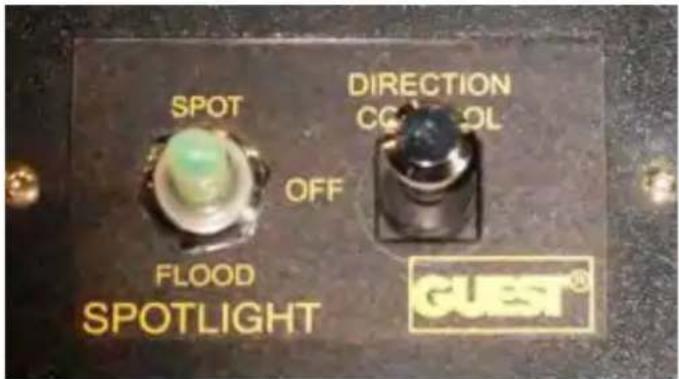
The spotlight control panel uses a 2 way switch to control the type of light output. To control the direction a 4 position joystick style switch is used.
The 2 way switch in the center position is "off". In the "up" position the light output is a spotlight. In the "down" position the light output is a floodlight.
To move the light upward press and hold the joystick "up". To move the light downward press and hold the joystick "down".
To move the light counterclockwise press and hold the joystick to port until the desired directional movement is achieved.
To move the light clockwise press and hold the joystick to starboard until the desired directional movement is achieved.
If storing the vessel outside in colder climates turn the spotlight so the lens faces the stern of the boat to help prevent a broken lens due to unidentified flying debris. Of course another option would be to cover the lens face.
SUN LOUNGE-FWD. DECK
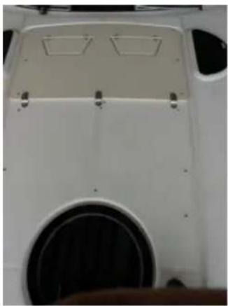
The forward deck features a sunpad. The 2-piece sun-pad cushion is lightweight making it easier to transport to the deck and easier to store. The backrest shown can be individually adjusted to several postions. The foredeck sunpad must be used only when the boat is stopped to avoid anyone falling overboard.
Make sure the cushions are
snapped down securely. It is a good idea to store the sunpad cushions when not in use to prevent them being blown overboard should the vessel encounter inclement weather conditions.
! WARNING
AVOID SERIOUS INJURY OR DEATH DUE TO FALLING OVERBOARD! DO NOT USE THE DECK SUNPAD WHILE BOAT IS MOVING.
SWIM (BOARDING) LADDER-TYPICAL
When using the swim (boarding) ladder open the hatch and slide the ladder out to the end of the travel. Then flip the ladder over and let it down gently. Make sure you keep your hands and fingers clear of any moving ladder parts especially the hinged top.
When not using the swim ladder be sure to keep the ladder cover over the ladder to prevent tripping and falling accidents.
Insist that only one person use the ladder at a time. When fi nished with the ladder fl ip up the lower section of the ladder and slide the ladder assembly in as far as possible. Lower the fi berglass ladder cover to secure it.
Periodically check the ladder hardware for tightness and corrosion. Replace fasteners and lubricate hinges as needed. Read and understand all warning and information labels found on the swim platform and ladder cover. Never exceed the maximum poundage recommended for the swim platform as noted on the label.
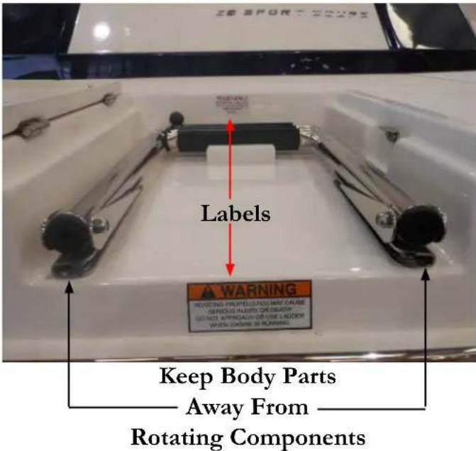
! WARNING
TO AVOID BODILY INJURY TURN THE ENGINES AND GENERATOR OFF AND REMOVE THE IGNITION KEYS WHILE PEOPLE ARE SWIMMING NEAR THE VESSEL AND/OR USING THE SWIM PLATFORM OR LADDER.
SWIM PLATFORM
The swim platform is used with the boarding ladder to enter and exit the water. Never dive from the swim platform or swim under it. The swim platform is not intended to be used for storing heavy objects. Keep the platform surface free of objects to prevent bodily injury due to falling. Periodically inspect all swim platform fasteners and stanchions under the platform for tightness and corrosion. Replace parts as needed.
Do not exceed the swim platform recommended pound-age capacity.
Use the swim platform cleats for temporary tying only such as stopping at an on-the-water restaurant or fuel dock. Use the other deck cleats for permanent moorings. When securing lines leave enough slack for local tidal changes.
Never use the swim platform cleats for towing! Never attempt to lift the boat using the swim platform cleats or any other cleats on the vessel! See the section on sling markers. Never swim around or under the swim platform while the engines are running due to the effects of carbon monoxide poisoning. Read and understand all CO labels in the safety on board chapter.
! WARNING
TO AVOID BODILY INJURY TURN THE ENGINES AND GENERATOR OFF AND REMOVE THE IGNITION KEYS WHILE PEOPLE ARE SWIMMING NEAR THE VESSEL, USING THE SWIM PLATFORM OR LADDER.
! WARNING
AVOID SERIOUS INJURY OR DEATH! NEVER OPERATE THE VESSEL WITH PEOPLE ON TOP OR HOLDING ON TO THE SWIM PLATFORM STRUCTURE OR HARDWARE.
THRUSTER-BOW (TYPICAL)
General Safety Notices:
- Be sure to read and understand the safety information and all thruster operation information before attempting to use the thruster system.
- Do not operate the bow thruster system close to swimmers as a high powered suction is produced at the propellers.
- Make sure the propeller lock nut is torqued to the required foot pound specification.
- When servicing the unit be sure to turn the thruster designated battery switch to the service position (to far-right) and insert a tie wrap in the selector slot for back-up protection. See the typical set-up below.
Below is a typical wiring layout (sump) for optional thruster (note that this one also includes the optional hyd. swim platform).
Using Thruster:

To use the thruster first make sure the house battery switch is activated. Next, energize the accessory switch on the helm starboard switch panel. This switch also controls the optional hydraulic swim platform should it be installed.
There is a joystick on the helm and it can assist in slow speed maneuvering especially around a dock or close mooring situations. It operates similar to the engine joysticks.
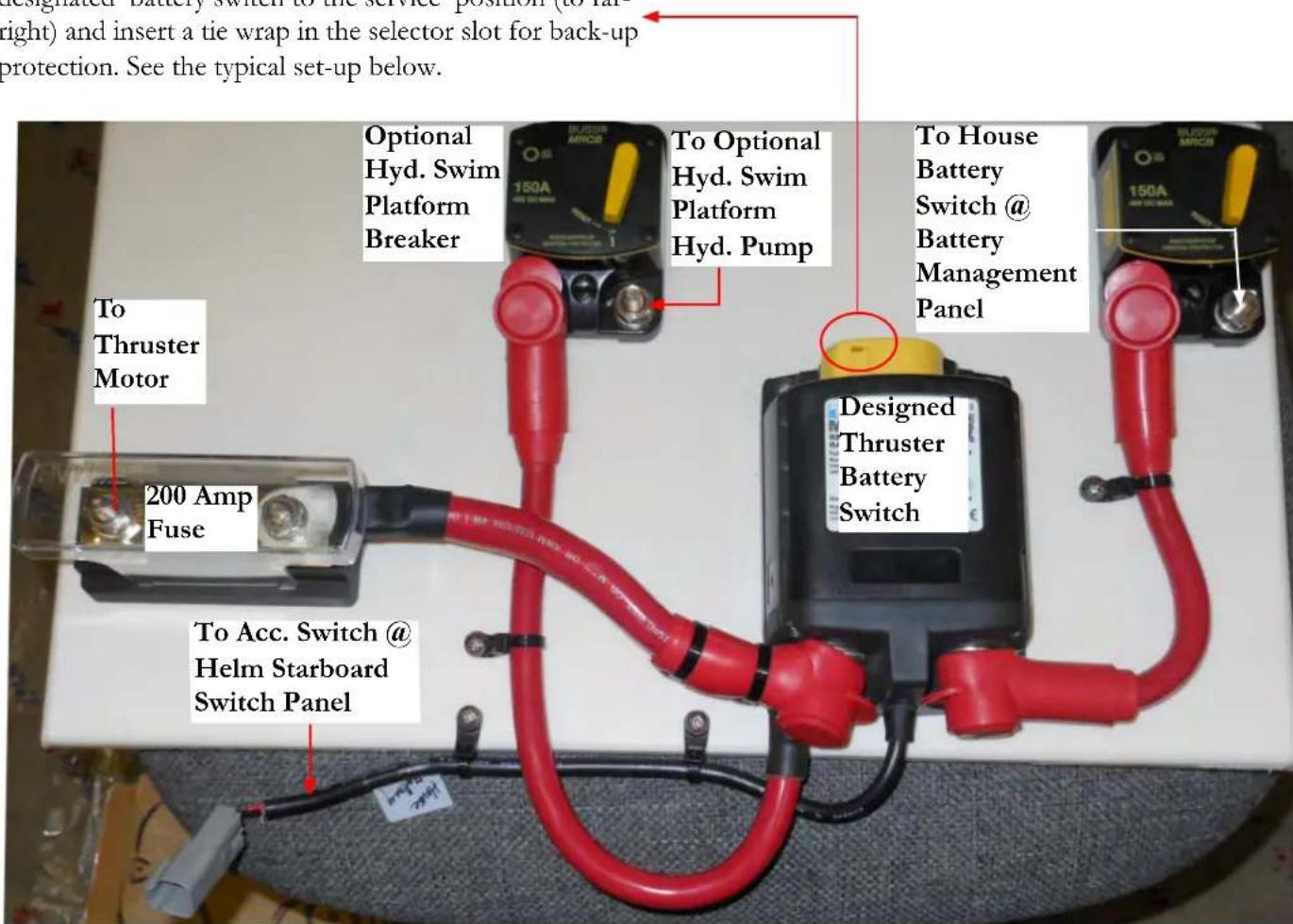
Never run the thruster dry; it will weld the relay contacts as it becomes a generator in spool down.
Do not make quick changes from one direction to the other direction, or it will damage the unit.
The minimum running voltage for the thruster is 10.5 volts; therefore the main engines should be running to maintain this voltage requirement.
ULTRA SUN LOUNGE-AFT

FORWARD FACING BENCH SEAT
The sun lounge features a forward facing aft bench seat with a four position backrest that features an aft facing sun lounge, a forward facing sun lounge, forward facing seating, and when the backrest is fl ipped all the way forward it becomes fl ush with the seat cushion and adds length to the sunpad. See the illustrations. The positioning handle is located at the port forward bench seat.
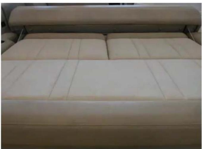
AFT OR FWD. FACING SUN LOUNGE
The oversized aft sun lounge maximizes the cockpit space. Also, by activating the arrowed switch at the port aft cockpit the bench seating can be slid 12" aft to add extra cockpit space for dockside entertaining. Before operating the boat be sure to move the engine hatch forward to eliminate any possible running problems due to having excessive weight too far aft on the vessel.
WARNING DO NOT OPERATE BOAT WITH ENGINE HATCH IN AFT POSITION!
UNDERWATER LIGHTING
OVERVIEW
The underwater light option provides high output, long life and low heat emission. The lights are made from a high impact resistant polycarbonate housing. The lights are installed under the transom for maximum efficiency. Their beam is blue for increased underwater penetration.
These lights are based on LED technology which stands for light emitting diode which can produce various colors depending on the electron line-up inside the semiconductor body of the device.
OPERATION
The underwater lights are energized through the accessory switch located at the starboard helm switch panel. The lights are protected by a breaker located at the helm under the steering wheel on the lower breaker panel.


Underwater Lights Shown
Cosmetic Care & Maintenance
COSMETIC CARE
This chapter covers the general care of your Regal boat. Be sure to read and understand all vendor supplied information on cosmetic care. Many cosmetic care topics are described and expanded in the following pages. For selected items there may not be specific vendor information available in the owner's information packet. Therefore, we have provided customer cleaning information as needed on each of these topics.
Where cleaning methods are suggested try them on a small area before applying to the entire surface. Never use toxic or caustic chemicals on your yacht. Read and understand each cleaning agent before using it. The labels will alert you to limitations and safety information for each cleaner.
Never mix cleaning agents since this may produce an unsafe chemical reaction which could be toxic, produce fire or explosion and/or effects that may be harmful to the human body.
Provide fresh air while using cleaning agents to reduce any effects of chemical inhalation by opening hatches, portlights and the main companionway door. It is recommended to vacate the area until any chemical odors are diminished.
Most of all, use common sense!
TABLE OF CONTENTS
COSMETIC CARE
| Bilge-Engine Compartment | 3 |
| Cabinets | 4 |
| Sunbrella Canvas Cleaning Instructions | 5 |
| Clear Vinyl, Zipper & Snap Care | 5 |
| Carpet | 6 |
| Countertops | 8 |
| Electric BBQ | 9 |
| Fabrics-Interior | 9 |
| Fiberglass & Gelcoat | 10 |
| Flooring | 12 |
| Gauges/Switch Panels | 13 |
| Hull/Deck | 14 |
| Microwave Oven | 14 |
| Plastics | 15 |
| Range | 15 |
| Spotlight | 16 |
| Stainless Steel | 16 |
| Stains | 17 |
| Upholstery | 18 |
MAINTENANCE
| Air Conditioner | 21 | |
| Batteries | 24 | |
| Battery Switch Management Panel | 28 | |
| Bilge Pump/Float Switch | 29 | |
| Carbon Monoxide Detector | 30 | |
| Door-Cabin Entry | 31 | |
| Electronics-General | 31 | |
| Electronics-VHF Marine Radio | 32 | |
| Fire Extinguishing System | 33 | |
| Fuel System | 34 | |
| Generator | 35 | |
| Ground Fault Outlet | 37 | |
| Heater-Hot Water | 38 | |
| High Water Alarm | 39 | |
| Horn | 40 | |
| Plumbing Connections | 41 | |
| Pump-Fresh Water | 42 | |
| Pump-Overboard Discharge | 43 | |
| Shower Sump Pump | 44 | |
| Stereo/DVD/TV | 45 | |
| Television Flat Screen Monitor | 46 | |
| Trim Tabs | 47 | |
| Underwater Hardware (Seacocks) | 48 | |
| Vacuum Style Toilet | 49 | |
| Vacuum Cleaner | 50 | |
| Windlass | 51 |
BILGE/ENGINE COMPARTMENT
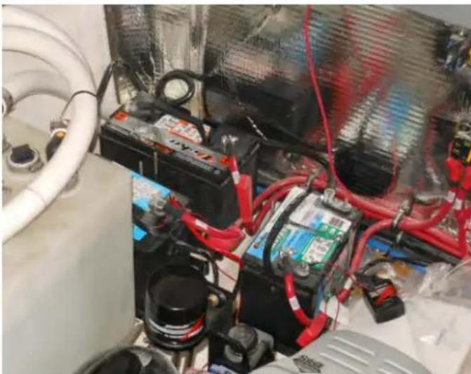
Always keep the bilge pumped out and free of accumulated debris. If oil accumulates on the engine compartment floor becomes it is usually related to engine oil lines, a loose component such as an oil filter, oil pan drain bolt or a leaky gasket/O-ring. Always find the cause of smaller problems before they become larger more expensive ones.
The engine compartment, bilge or sometimes called the sump features a light colored gel fi nish that will be beneficial in fi nding leak sources.
A periodic bilge cleaning with a brush and bilge cleaner (purchase at a marina or supplier) will be helpful in maintaining an orderly and safe bilge since accumulated dirt and fluids could cause someone to fall. Do not pump bilge contaminated oil overboard but deploy it to a waste receptacle for recycling. Check the fuel system including all hoses, tanks and connectors for possible leaks and deterioration. A stained area normally could suggest a hose or connection leak.
Inspect all wiring including connectors and hangers for tightness. Clean fuel filters as suggested by the engine manufacturer.
Check all engine and water/waste hoses for tightness and deterioration. Tighten all hose clamps as needed.
Check all battery hardware and terminal connections. Fill the battery cells with distilled water (wet-cell type only) to the battery manufacturer's suggested level.
Check the transom area for loose hardware. With IPS systems refer to the vendor owner's manual for any engine room maintenance on the stern drive system.
Do not use any flammable products in the bilge. Use environmentally approved procedures to dispose of oily or soiled cloths.
CABINETS
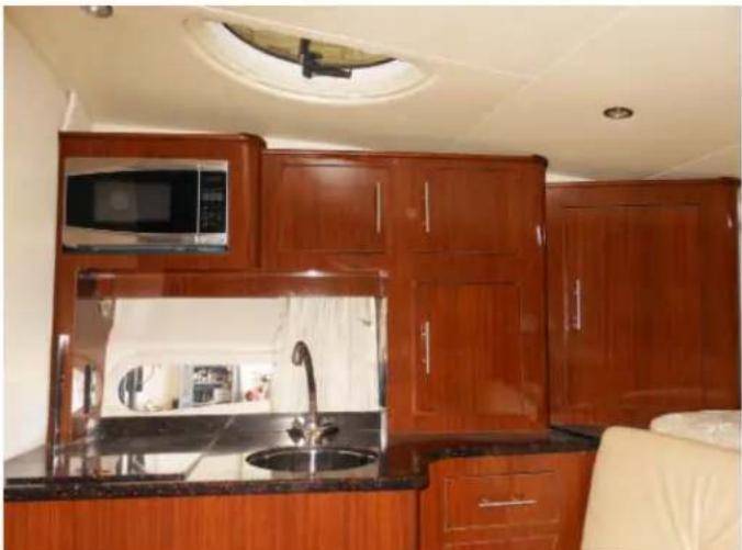
The handcrafted interior cherry cabinets feature a sprayed clear coat fi nish. This clear coat produces a hard fi nish which is baked on and is very resilient. Use a warm solution of water and mild detergent to keep the cabinet surfaces looking new. Wipe the surface with the solution using a soft damp cloth, and dry with a soft clean towel. This procedure should eliminate most stains and oily fi nger marks. Stay away from heavy scrubbers and compounds which may harm the surface. Avoid polishes containing silicones.
Use the specifications below as a guide for any cabinet repairs or interior refurbishing needs.
| APPLICATION ADHESIVE | |
| WOOD TOWOOD | WOODGLUE |
| WOOD TOFORMICA | CLEARSILICONE |
| FORMICA TOFORMICA | CLEARSILICONE |
| SINK INSTALL | CLEARSILICONE |
| CORIAN TRIM | SIKA FLEX291 |
| MIRROR TOFORMICA | MIRRORMASTIC |
| GRANITE TO WOOD | SIKA FLEX291 |
CANVAS CLEANING INSTRUCTIONS
Sunbrella type canvas should be cleaned regularly before substances such as dirt, roof particles, etc., are allowed to accumulate on and become embedded in the fabric. The fabric can be cleaned without being removed from the boat. Simply brush off any loose dirt, hose down, and clean with a mild solution of natural soap in lukewarm water. Rinse thoroughly to remove soap. DO NOT USE DETERGENTS! Allow to air dry.
For heavily soiled fabric, remove the top from the frame. Soak the fabric in a solution that has been mixed to the following proportions: 1/2 cup of Clorox bleach and 1/4 cup of Ivory or Lux soap (liquid or soap) per each gal lon of lukewarm water. Allow the fabric to soak until the bleach has killed the mildew and the stains can be brushed out with a common kitchen scrub brush. Rinse the fabric thoroughly in cold water to remove all the soap. This may require several rinsings. Incomplete rinsing can cause deterioration of sewing threads and prohibit the fabric from being properly retreated. Allow the fabric to dry completel Do not steam press or dry in a gas or electric dryer.
Excessive heat can damage and shrink the fabric since it is heat sensitive.
This method of cleaning may remove part of the water and stain repellents that was applied to the fabric during its manufacture. It is recommended to retreat with such water repellency products as Apseal and Uniseal. We do noenvironments. recommend any wax based treatments such as Thompson's Water Seal or any of the silicone products such as SC-15 or Aqua-Tite. Wax based products prevent the fabric from breathing, and encourage mildew growth while the silicone products interact with the original fluorocarbon fi nish and seem to cause a rapid loss of water repellency. Scotchguard has not been found to be very effective for restoring water repellents to Sunbrella. It seems to work well in the short run, but not long term.
CLEAR VINYL, ZIPPER & SNAP CARE
Never store canvas wet or in an unventilated, moist area. Always roll the canvas instead of folding. This is of particular importance on side curtains or any other part with the clear vinyl “glass”. Roll the top carefully around the bows and cover with the storage boot provided.
The clear vinyl “glass” used in side curtains, aft curtains, visors, and camper enclosures is very susceptible to heat and cold. Keep vinyl curtains from touching metal tubing to minimize burning the vinyl.
If the boat is stored with top, side curtains and aft curtain in place, heat build up inside the boat may discolor the vinyl.
To clean the clear “vinyl” glass, use a solution of Ivory or Lux soap, liquid or flakes, and lukewarm water. Allow to air dry. Never use any type of abrasive cleaner as it will scratch the “vinyl” glass. There are many cleaners and -scratch removers on the market specifi cally for clear vinyl. Handle the clear curtains carefully. They are soft and prone to scratching.
Canvas parts are designed with zippers. When zippers are new they can be a little difficult to use. Zip carefully without forcing the zipper or the material. They will loosen with use. A zipper lubricant may be used to help new zippers as well as maintaining used ones. The most vulnerable part of the zipper is the starts. Use care when starting the zipper.
Canvas snap fasteners should be unsnapped as close to the button as possible. Never remove canvas by pulling roughly on the edge of the material. This can damage the canvas as well as the fasteners. Use petroleum jelly on snaps to keep them from developing corrosion especially in harsh
CARPET-INTERIOR
The interior cabin carpet is produced from 100% BCF nylon. The nylon is treated tropically with an anti-soil chemical that will assist in keeping your carpet looking beautiful longer.
General Care and Maintenance
Your carpet is a high luster nylon that can look great for years to come provided you follow some basic care and maintenance. Nylon is the highest performing synthetic fi ber in the market and has dense pile that will give a long wear cycle and high performance.
The following will help maintain your carpet:
Regular Vacuuming
This is the most important single factor in keeping carpet beautiful is to vacuum it on a regular basis. Sand and dirt particles will abrade the carpet fi bers in a faster manner. This abrasion will cause non-repairable damage to the fi ber that will reduce the carpet's life expectancy. Use a vacuum with a beater bar verses a vacuum alone as it will lift the fi ber and help open the carpet to allow the vacuum to remove grit.
Professional Cleaning
Interior carpet is the same as high-end residential carpet and the carpet should be treated accordingly. Periodic professional carpet cleaning using either the hot water extraction or dry cleaning powder method will help manintain the beauty of your carpet. This will remove the ground in soil.
Spills
At some point in the life of the carpet, there is always the potential for a spill. Remove the spill immediately. The quicker the spill is removed, the easier it is to clean up. The longer a spill stays on the carpet, the more likely it is to stain the fibers, regardless of the cleaning treatment used. When a spill occurs, always blot the area being cleaned. Do not rub or scrub. Follow the cleaning instructions.
Cabin Door/Cockpit Entrance Mats
Entrance mats on a boat are very important to help reduce the dirt and sand that is brought on to the carpet. Also, entrance mats reduce the amount of moisture being tracked on to the carpet, which will cause matting of the fibers. Mats can be ordered from your Regal dealer. These mats fit the nautical decor and provide the best surface to catch dirt and sand particles. Also, entrance mats can be obtained from local sources. Look for mats with a non-skid backing.
CARPET-COCKPIT TYPICAL
Regal cockpit carpets feature an aqua tread backing which permits the carpet to weep moisture and still retain steadfast non-slip characteristics. Also, this backing permits the cockpit carpet to lay fl at on the fi berglass deck surface without buckling.
Also, your cockpit carpet is produced with 100% ultraviolet resistant fi bers. The carpet boasts a special blend of resilient fi bers to withstand traffic and retain its beauty. Cockpit carpet is designed to take a lot of abuse from the sun and sea but it periodically needs to be cleaned which is a different procedure from household types.
To clean cockpit carpet follow these steps:
-
Scrub the soiled areas with a stiff nylon or soft bristle brush to loosen the dirt and grime.
-
Vacuum the carpet thoroughly using a wet-dry type of cleaner.
-
Pour one cup white vinegar into a 1-quart spray bottle; fill with water.
-
Spray the soiled areas with the vinegar solution until saturated; let stand 15 minutes.
-
Brush the soiled areas once more; the dirt and grime will be released from the carpet fibers.
-
Rinse the carpet, with a garden hose at low pressure.
-
Remove any remaining water with a wet-dry vacuum. Allow the carpet to dry completely.
-
Fluff up the clean, dry carpet with the brush or a carpet rake. If applicable, apply vaseline to the snaps.
Stain Removal
Olefii fi ber used in the cockpit carpet is very resistant to stain. However, when a stain does occur, follow the stain removal chart on the following page. Remember, remove a stain as soon as possible, as this enhances the ability to remove it.
Most stains should easily be removed from olefin fibers. If the stain persists, the cleaning procedure should be repeated to ensure stain removal. Again, the sooner the stain removal process is started, the easier the stain will be to remove.
Under no circumstances should any solvents normally associated with the dry cleaning of apparel (perchlorethylene, carbon tetrachloride, etc,) be utilized, as permanent damage to the fi ber will result.
Cockpit Carpet Stain Removal Chart
| Miscellaneous Stains | Removal Process |
| Coffee, Tea, Coke, Fruit Juice, Ice Cream, Motor Oil, Egg, Grease, Catsup, Chocolate, Milk, Rust, Latex Paint, Water Colors, Berry Stains, Blood, Salad Dressing, Furniture Polish, Clay, Wine, Dye, Mayonnaise, Fish Formula or Urine | Apply warm water and household detergent in minimal amounts to the stained area. Sponge or scrape the stain until it is removed. Then wash thoroughly with clean water. |
| Persistent Stains Removal Process | |
| Chewing Gum, Crayon, Ink, Wax, Lipstick, Tar, Polish, Oil Paint | Apply warm water and household detergent. Work mixture well into the stained area, and then flush with warm water. |

To store cockpit carpet, roll it tightly. This will keep the carpet from developing wrinkles which result from folding the carpet.
COUNTERTOPS
Solid surface countertops feature elegance and durability. Periodic maintenance will ensure its beauty. It withstands heat much better than ordinary countertop materials but you must still use a hot pad or trivet when taking materials directly out of the oven or stove top to protect from damaging the surface. Avoid cutting directly on the surface.
Another feature of solid surface countertops is that they are non-porous. Therefore, dirt and germs do not penetrate it. Also, it will not support the growth of germs and mildew. To disinfect or clean see the table. You can use a green Scotch-brite pad along with the table solutions to remove stubborn stains.
Darker colors tend to require more frequent cleaning to maintain a uniform fi nish. Also, darker colors tend to show fi ne scratches more easily and require more attention than lighter colors.
The material is a matte or satin fi nish. To remove scratches and nicks, sand the surface with 180-220 grit sandpaper until the nick is gone. To restore the fi nish use an abrasive cleanser and a green Scotch-Brite pad. Wrap the sandpaper around a block of wood. The block will sand the areas fl at instead of creating hills and valleys.

| PROBLEM SOLUTION | |
| Dirt and Residue Use soapy | water, ammonia based cleaner (not window cleaner), rinse and wipe completely dry.Commercially available solid surface cleaners such as Clean Encounters® will work well too. |
| Preventing Hard Water Marks | Rinse & wipe completely dry after cleaning; clean up spills before they dry. |
| Removing Hard Water Marks | Use a cleaner formulated for removing hard water marks such as CLR or Lime-A-Way |
| Difficult Residue Spray residue with Deep Cleaner for DuPont Corian from Stone Care International. Follow instructions on the bottle. Wash area with soapy water, rinse and wipe completely dry. | |
| Disinfecting | Occasionally, wipe surface with diluted household bleach (1 part water/1 part bleach). Rinse top thoroughly with water and wipe completely dry. |
ELECTRIC BBQ
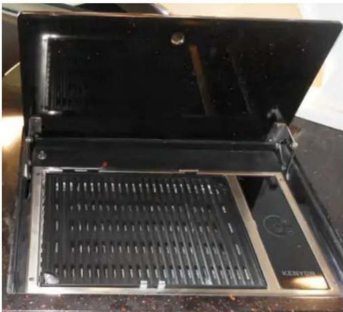
STAINLESS STEEL SURFACES
The best way to clean metal surfaces on your BBQ is to wipe them down with a damp cloth and then thoroughly dry. Stubborn spots caused by spillage and discoloration from heat may be removed by lemon juice, vinegar, or chrome polish. Keep these cleaning products away from porcelain enamel surfaces. Never use coarse cleaners, steel wool scouring pads or metal brushes to clean stainless steel. These methods will allow deep scratches to develop on the stainless steel that cannot be removed.
PORCELAIN ENAMEL
Porcelain enamel is glass fused on steel at very high temperatures. It is not overly delicate but must be treated like glass. Sharp blows, radical changes in temperatures, etc; will cause the enamel to crack or chip. Some foods contain acids which will dull the finish of the enamel.
FABRICS-INTERIOR
Clean flat at good interior fabrics with dry cleaning fluid style cleaners approved for use with soft fabrics. Allow adequate ventilation and follow the label instructions carefully. Use protective eye wear and gloves. Do not inhale the chemicals.
Use a soft cleanser with feldspar to clean stubborn marks or stains on wallpaper.
Normal interior vinyl such as the headliner need a mild soap and water solution. Rinse immediately with clean water and wipe dry. Always test a small area with a cleaner before applying it to a larger area.
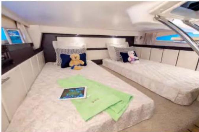
FIBERGLASS & GELCOAT

Routine maintenance is the only practical way to keep the surface of your boat looking shiny and new. Most objects left outdoors will gradually deteriorate from exposure to the sun, water, dust and pollution. Such outdoor exposure can cause your boat's gelcoated surface to change or fade. Darker colors tend to fade more rapidly than lighter colors because they absorb more of the sun's rays (ultraviolet and infrared).
Basic maintenance includes monthly washing of the boat's surface to remove normal accumulation of soil and stain. Use a mild detergent such as dishwasher powder or liquid. Do not use automatic dishwasher detergent. Avoid any kind of alkaline cleaners such as tri-sodium phosphate (TSP), abrasives, bleaches and ammonia. For best results use cleaners that are recommended for fi berglass.
It is recommended that you wax the gelcoat surface twice yearly to prevent loss of gloss and to protect the fi nish. Use only waxes for fi berglass and follow the label instructions. Apply a 3' x 3' section at a time using clean applicator cloths or a buffi ng bonnet. When a haze develops, use a power buffer at low speeds (1200-2000 rpm) to remove the haze. Keep the buffer moving to avoid heat build-up. Never wax gelcoat in direct sun.
When the washing and waxing as recommended does not restore the shine it may be necessary to use a fine rubbing compound. Do not apply rubbing compound in direct sunlight. A power buffer at lower speeds does an excellent job to remove impurities from the gel coat that cause dulling. Use light pressure and keep the buffer moving. Re-wax after compounding to buff the surface.
"Hairline cracks" or "spider webbing" could develop in the gelcoat surface of a hull or deck. This can be caused by impact or other factors. Small air pockets or gouges may also occur through normal wear. These do not affect the strength of the hull or deck and can be repaired by yourself, a marine professional or a Regal dealer.
The affected area should be chipped or sanded away and a thin layer of color matched gelcoat applied. This layer is then sanded smooth and buffed to its original luster. Most minor scratches, nicks, and dents can be removed by compounding the surface. Marine type compounds can be found at most auto body supply stores.
Specify a number 25 which is a coarser compound up to a number 55 being less coarse. Various glazes and polishes are available as needed. Ask your marine professional or Regal dealer for more information. Fiberglass hulls are strong but they can be damaged. A fi berglass hull has virtually no internal stresses. Thus when a part is broken or punctured, the rest of the hull retains its original shape. A severe blow will either be absorbed or result in a definite localized break. A break of this nature should be checked and repaired by a marine professional or a Regal dealer.
MINOR REPAIRS
You will need the following materials for minor repairs:
• Gelcoat
- Clear Liquid Catalyst
• Putty Knife
- Razor Blade
• Fine Sandpaper (400,600,1000)
• Wax Paper (to cover repair area)
WARNING
AVOID BODILY INJURY! GELCOAT & FIBERGLASS RESIN ARE FLAMMABLE. WORK IN A WELL VENTILATED AREA FREE FROM OPEN FLAMES. DO NOT SMOKE!
For minor repairs refer to the following procedure:
- Clean the area to be repaired and get rid of any wax or grease residues.
- Clean out scratches, chips, and nicks.
- Sand area to be repaired so gelcoat will bond.
CAUTION
AVOID BODILY INJURY! WAXED GELCOAT SURFACES CAN BE VERY SLIPPERY. DO NOT WAX NORMALLY USED AREAS OF THE DECK, LINER, OR GUN- WHALES. DO NOT WAX ANY TEXTURED OR NON-SKID SURFACES SUCH AS FLOORS, WALKWAYS, STEPS, LADDERS OR SWIM PLATFORMS. ALWAYS WEAR NON-SLIP FOOTWEAR WHILE ON BOARD THE VESSEL.
- In a separate container, measure only the amount of gelcoat you will need. Mix a ratio of 2% ratio of catalyst to the amount of gelcoat being used (a spoonful of gelcoat will require only a drop or two of catalyst). Do not pour any unused portions of the gelcoat/catalyst mixture back into either original container.
- Apply gelcoat to area leaving a slight lift above the surface.
- Cover the area with wax paper. It will help the mixture to set up faster.
- Remove wax paper and shave off any extra gelcoat with a razor blade.
- After the area is shaved smooth, start with the 400, 600, and finally 1000 grit sand papers.
- Buff the area with compound, polish and a fi nish wax. You may notice a difference between the repaired area and the original fi nish due to the natural weathering process.
FLOORING-HARDWOOD

Your vessel may have engineered hardwood floors highlighting the interior. Your flooring was chosen because of its beauty, durability and care-free maintenance. Several types have or are being used including light maple, walnut, cherry, cherry-holly, and bamboo.
Here are some do's and don'ts to follow in keeping your marine flooring looking new:
First, do remember that if you have been cleaning residential floors with vinegar and water, oil soap, furniture polish or window cleaner, you may be ruining your costly investment. These cleaners are a big no with hardwood floors.
Excessive wet mopping with water and vinegar can cause wood to expand, possibly permanently damaging the floor in addition to dulling the finish. Other cleaners that have silicone, wax or oil soaps can leave a residue on the finish and may cause the floor to be slippery which is what you do not need with a boat.
One residue-free, proven hardwood floor cleaner formulated specifically for polyurethane-finished hardwood floors is BonaKemi's Swedish Formula® Hardwood Floor Cleaner. This environmentally friendly, non-toxic, ph-neutral cleaner effectively cleans dirt, grease and sticky spills without leaving any dulling residue. Apply per container directions.
Preventative care of your floors is also extremely important for keeping hardwood floors looking like new. Vacuuming or sweeping floors regularly, promptly removing spills, and placing mats at cabin door and cabin stairway landing can be effective in trapping damaging sand and dirt particles before they can damage the floor. Avoid walking on floors with high heel shoes. Walking or tennis shoes with soft soles are better and safer to help prevent falls while on the vessel. The harder heels especially black ones tend to leave scuff marks on the floor surface. It is a good idea to keep the nails of pets trimmed, too.
Note: Use a soft application pad inserted in a long handle to apply product. Rinse often in a clean bucket with warm water which are available at most "box" stores.
GAUGES/SWITCH PANELS
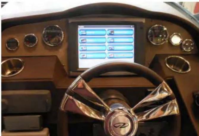
For normal dirt and dust accumulation clean with soft cloth and warm water. Dry with a soft cloth or chamois.
Near salt water environments deposits can build up on the instrument bezels and faces. Use a soft damp cloth to remove the deposits. Do not use abrasives or rough, dirty cloths to wipe instruments.
Follow the same procedure for all switch panels. Do not use any of the following on panels:
- Lacquer Thinner
- Dry Cleaning Fluid
- Acetone
- Carbon Tetrachloride
- Benzine
- Silicone Spray
- Gasoline

Sometimes gauges develop condensation inside their faces. in high humidity envi ro nm en ts. To el im in at e the condensation droplets, energize the instrument lighting and the heat over a short period of time This process will evaporate the gauge condensation.
HULL/DECK
HULL BOTTOM
Never use wire brushes or highly abrasive scouring pads on your hull bottom. It could damage the gelcoat surface or the bottom paint. The bottom of your boat needs to be clean since the build up of natural coatings from water or marine life can potentially create drag and affect boat performance. Use a turkish towel or for heavier build-up a piece of rug to clean the bottom.
HULL/DECK
MICROWAVE OVEN

- Turn off the oven.
- Keep the inside of the microwave clean. When food splatters or spilled liquids adhere to oven walls, wipe with a damp cloth.
A mild detergent may be used on extremely dirty surfaces. Avoid the use of sprays and other harsh cleaners as they may stain, streak, or dull the door surface.
For normal dirt and insect residue find a soft bristle brush on a long telescopic handle at an automotive store. A good brush is designed with a curved soft base to protect objects it comes in contact with while scrubbing. Rinse down the hull with a hose to loosen up the dirt. Use a mild soap solution in a bucket. Use up and down strokes to clean the hull sides. Rinse off until all residue is removed.
-
The outside surfaces should be wiped with a damp cloth. To prevent damage to the operating parts inside the oven, water must not enter the ventilation openings.
-
Wipe the door and window on both sides, along with the door seals and related parts frequently with a damp cloth to remove any spills and splatters. Do not use any abrasive cleaner.
-
Do not allow the control panel to become wet. Clean with a damp cloth. When cleaning the control panel leave oven door open to prevent the oven from accidentally turning on.
-
If steam accumulates inside or outside of the oven door, wipe with a soft cloth. This may occur when the microwave is used in high humidity conditions and this is normal.
-
It is occasionally necessary to remove the glass tray for cleaning. Wash the tray in warm sudsy water or in a dishwasher.
-
Remove odors from your oven by combining a cup of water with the juice and skin of one lemon in a deep microwaveable bowl, microwave for 5 minutes. Wipe thoroughly and dry with a soft cloth.
CAUTION
AVOID BODILY INJURY! GELCOAT SURFACES CAN BE VERY SLIPPERY.
ALWAYS WEAR NON-SLIP FOOTWEAR WHILE ON BOARD THE VESSEL.
ALWAYS RINSE SURFACES ADEQUATELY TO AVOID SLIPPING ON SOAPY SURFACES!
PLASTICS
There are different types of plastic aboard your vessel. Use plastic cleaners and polishes recommended for marine use only. Use proper applicators. Read all instructions carefully. Test the product in a small area fi rst. Use a soft rag and always rinse the surface with water. Ammonia based cleaners will damage plastic parts.
One of the basic rules to cleaning plastic is never used abrasive cleaning products. Even hard plastic surfaces are easily scratched. Stay away from steel wool pads, powdered cleaners with abrasive qualities, or harsh detergents.
Instead use sponges, soft cloths, and mild detergents when cleaning plastic.
While cleaners in aerosol cans are convenient they may not be the best for certain types of plastic. Glass cleaner in a can or a spray bottle is not safe to use on your marine toilet fixture or toilet seat. Many times pits will develop over time and the toilet/seat will appear mottled and will not appear clean no matter how hard you scrub.
Refer to a marine store which possesses the expertise and experience to assist the boat owner in selecting the right cleaner for his marine plastic onboard needs.
NOTICE
NEVER CLEAN PLASTIC SURFACES WITH A DRY CLOTH OR GLASS CLEANING SOLUTIONS CONTAINING AMMONIA. NEVER USE SOLVENTS OR WIPE WITH ABRASIVES.
RANGE/STOVE

Clean the cook top before you use it for the first time. A thorough cleaning with a recommended product such as Cerama-Brite Cook Top Cleaner will put a clean shiny coating on the cook top before its initial use.
Always remove food spills, grease splatters, and metal rub-off from utensils. First, use a razor blade scraper to remove all spillovers. Then clean the cook top with a paper towel or a clean soft cloth and a recommended cleaner.
After using any cleaner always wipe the cook top with a clean, damp cloth (to avoid burned-on cleanser residue) and wipe dry.
Do not use your dish towel or sponge to wipe off the cook top. This may leave a film of detergent of other matter that can cause discoloration the next time the cook top is heated.
Avoid abrasive scouring powders of any kind. Also, avoid using plastic, nylon or metal cleaning pads. They may scratch or melt onto the cook top. Avoid chemical cleaners such as chlorine bleach, ammonia, hydrofl uoric acid or chemical oven cleaners. They may etch or discolor the surface.
Do not let anything that melts such as plastics, aluminum foil, or sugar to come in contact with your cook top surface when it is hot. Should something melt onto the surface, immediately move it to a cool area of your cook top with a razor blade scraper, and then remove it from the cook top as soon as possible.
SPOTLIGHT
The spotlight lens should be wiped with a clean, dry soft cloth to remove any debris such as bugs, salt spray or general dirt. Read the manufacturer's literature for more information.
STAINLESS STEEL

Stainless steel is an alloy made from nickel, chromin and iron. It has been very successful in marine environments due to its ability to resist rusting. If the stainless steel product such as a bow rail is exposed to elements such as ocean spray it will begin to rust over time. If your stainless steel shows signs of rusting:
- Wash with fresh water.
- Clean with a good quality chrome polish periodically but no less than annually. "Brasso" is another product that works well.
- Also, using a good quality car wax will provide extra stainless steel protection.
- For polished fi nishes that show grit lines an abrasive such as “Scotch Brite” or sand paper can be used. Always test a spot fi rst and “go with the grain”.
Do not use harsh solvents or cleaners on stainless steel. Do not use steel wool or wire brushes. They will damage the finish. Do not use any type of acids.
STAINS
Below is a listing of normal stains and clean-up methods.
The sooner the stain is removed there is less chance of permanent residue on the surface.
Do not use wire brushes, solvents or harsh chemicals on any stain. Damage to the surface will occur.
FREQUENT STAINS CLEAN-UP STEPS
1 2 3
Coffee, Tea, Chocolate...... B
Permanent Marker*...... E B C
Household Dirt...... A B
Grease...... D B
Ketchup, Tomato Products...... A B
Latex Paint.... A B
Oil Base Paint.... D B
Mustard.... A B C
Suntan Oil.... A B
Asphalt/Road Tar...... D B
Crayon...... D B
Engine Oil...... B
Spray Paint...... B
Chewing Gum...... D A
Shoc Polish*...... D B
Ballpoint Pen*...... E B A
Lipstick...... A B
Eye Shadow.... E B
Mildew * C B A
Wet Leaves *...... C B A
A= Soft brush; warm soapy water/rinse/ dry
B= Fantastik cleaner
C= One tablespoon ammonia, 1/4 cup of hydrogen
peroxide, 3/4 cup of warm water/ rinse/dry
D= Scrape off residue ( use ice to lift gum)
E= Denatured alcohol/rinse/dry
* These products contain dyes which leave permanent stains.
UPHOLSTERY
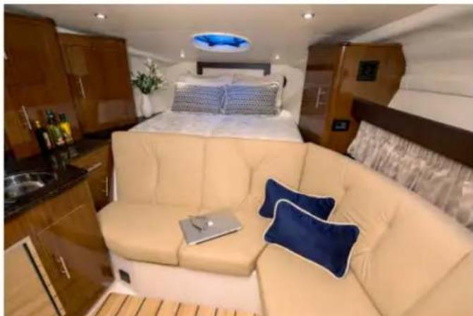
Powdered abrasives, steel wool, or industrial strength cleaners are not recommended for cleaning our vinyl. Lacquer solvents will cause immediate damage. Dilute chlorine bleach before using. Do not wax the vinyl as it may cause cracking. Always wear protective gloves and make sure there is sufficient ventilation when cleaning vinyl. Wear eye protection.
Remember that suntan oil will damage vinyl. Use suntan lotion instead of suntan oil. Exposure to the sun is a natural enemy of vinyl upholstery. For maximum life, use a cockpit cover when the vessel is moored, docked or stored.
Cockpit vinyl requires periodic cleaning to maintain a neat appearance and to prevent the build up of dirt and contaminants that may stain and reduce the vinyl life if they are not removed. The frequency of cleaning depends on the amount of use and conditions to which the vinyl is subjected.
Most common stains can be cleaned using warm, soapy water and clear rinses. Scrubbing with a soft bristle brush will help loosen soiled material from embossed surfaces and under welting. If the stains are not removed with the above method use a mild cleaner such as Fantastic. This cleaner should be used only as needed and not the normal means.
With more stubborn stains, rubbing alcohol or mineral spirits may be tried cautiously. Widespread solvent use can severely damage or discolor vinyl.
Try to remove stains immediately before they have a chance to penetrate the surface of the vinyl.
Ballpoint Pen Removal Instructions
- Wipe the stain off with ethanol (rubbing alcohol).
- Prepare a solution of 50% non-chlorinated bleach, 50% water.
- Place a thin line of tissue over the ink stain.
- Apply the non-chlorinated bleach solution to the tissue. Be sure not to saturate the tissue.
- Cover tissue with polyethylene film (plastic wrap) to prevent the non-chlorinated bleach solution from drying.
- Check on stain repeatedly.
- Do not leave the non-chlorinated beach solution on for more than 1 hour.
When the stain looks almost gone, remove the tissue and wash the stain with water. - To neutralize the bleached area, place tissues on the bleached area and apply 15% hydrogen peroxide solution.
- Leave on for 30 minutes, & then remove the tissues.
- Remove the peroxide residue with water.
MAINTENANCE

This section covers maintenance procedures on selected standard and optional Regal installed and/or related equipment. Engine and propulsion equipment, electronic and specific entertainment components are found by referring individual vendor information located in the owner's information packet. The engine/propulsion and generator owner's manual are quite detailed and should be read and understood before attempting to undertake any maintenance issues. Heed special attention to all caution, warning and danger labels found in the engine/propulsion and generator manual. Also, the major electronic and entertainment components are outfitted with detailed system descriptions, wiring schematics, and contact information. The internet can be helpful for select maintenance issues. Numerous web-sites are currently available from vendors on their particular product maintenance procedures and schedules.
AIR CONDITIONER:
Before each outing inspect the thru-hull fitting for leaks. Make sure the seacock is open. Also, the sea water strainers located under the engine room center walk-thru should be checked periodically for foreign objects and accumulated debris. To clean the strainer, first position the seacock handle to the "off" position. Unscrew the strainer fasteners by turning counterclockwise, remove the wire strainer, and blow it out if possible with compressed air. Reinstall the strainer, make sure the gasket on the top of the seacock is centered, and tighten the fasteners. Check for leaks since sucking air into the system could cause the seawater pump to malfunction. See the illustration.
Inspect the air filter monthly. The air conditioner filter is located at the condensation unit at both forward and aft A C units. To clean the filter remove it and rinse with plenty of fresh water. Blow with compressed air as needed.
Check the AC hose output located on the hull side for a full discharge when the AC pump is running. If there is little or no discharge shut down the unit and immediately find the cause of the problem.
Periodically check the drain located at the compressor to make sure the entrance to the hose at the AC pan is not clogged with foreign matter.
If clogging occurs, blow out the hose with compressed air and pour in a bleach/water solution at 5/1 parts water to bleach.
Be sure to read and understand the A/C owner's manual before attempting any maintenance. It covers the operating system and equipment more thoroughly than can be done here. Pay close attention to all safety labels since both high-pressure and high voltage are part of the A/C system.
WARNING
TO PREVENT BODILY INJURY OR DEATH! DUE TO THE HIGHLY PRESSURIZED REFRIGERANT FOUND IN THE AIR CONDITIONER UNIT, DO NOT LOOSEN OR REMOVE ANY FITTINGS.

TYPICAL COMPONENTS SHOWN
WARNING
TO PREVENT BODILY INJURY OR DEATH! DISCONNECT THE A/C BREAKER AT THE MAIN A/C PANEL BEFORE OPENING ANY COVER ON THE A/C UNIT.
REVERSING VALVES
All reverse cycle units use a reversing valve: the valve must be energized periodically to keep the internal parts moving freely. To do this, switch the AC unit into heat for a few seconds once a month.
SEAWATER STRAINER
Check the AC pump for proper seawater flow by cleaning the seacock strainer basket. Check the overboard discharge for proper water flow. Check seawater intake speed scoop for obstructions. Make sure hoses are not looped, kinked or crushed.
TYPICAL VECTOR COMPACT AC SYSTEM

CONDENSER COIL CLEANING
Note: It is best to get an air conditioning expert familiar with marine a/c to do the periodic maintenance mentioned below. The information will assist the technician.
- With the system turned off at the ship's AC electrical panel, disconnect the inlet and outlet connections of the condenser coil.
- Use chemical resistant hoses (MAS white PVC 5/8" I.D. etc.) to connect the inlet of the condenser coil to the outlet of a chemical resistant, submersible pump (MAS P-500 pump, etc.) and let the hose connected to the coil outlet flow freely into the container mentioned below.
- Place a strainer or piece of screen over the inlet of the pump and submerse the pump into a container filled with a 5% solution of muriatic or hydrochloric acid and fresh water or use a premixed over-the-counter solution. Use as large a container as possible to hold the solution (2 to 5 gallons).
CAUTION
AVOID BODILY INJURY! AVOID SPILLING OR SPLASHING THE SOLUTION. FOLLOW THE WARNINGS AND RECOMMENDATIONS GIVEN BY THE MANUFACTURER OF ANY ACIDS OR PREMIXED SOLUTIONS.
- Circulate fresh water through the coil to flush any residual acid from the system.
- Restart the system and check operational parameters to ensure thorough cleaning has taken place. Additional cleaning may be necessary with extreme contamination.
NOTICE
FOR THE PURPOSE OF PROTECTING THE ENVIRONMENT, DISPOSE OF ANY CONTAMINATED ACID SOLUTIONS IN ACCORDANCE WITH FEDERAL, STATE AND/OR LOCAL REGULATIONS
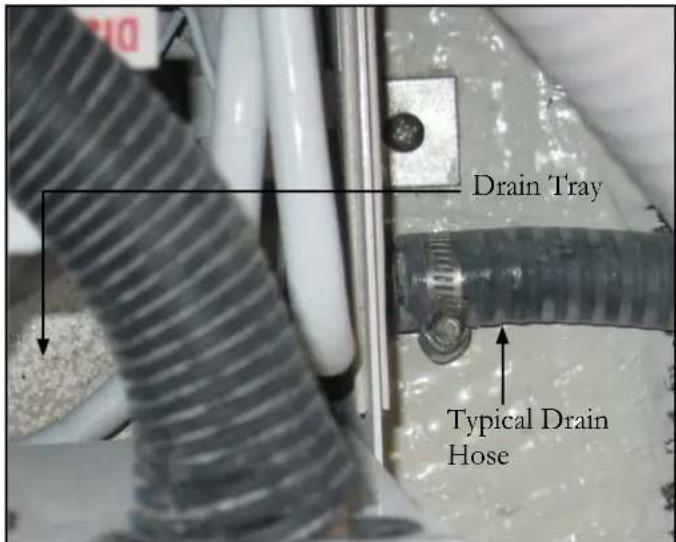
AIR FILTERS
- Power the pump and circulate the solution through the condensor coil for 15-45 minutes depending on the size of the coils and the extent of the contamination. Visual inspection of the solution in the container should indicate when the contamination removal has stopped.
Check the air filter located at both A/C condensation units monthly and clean as necessary. To clean the filter, remove it from the unit, rinse with water, air dry and reinstall. Blow with compressed air as needed. See the illustration on the preceding page.
BATTERIES
Periodically check your battery terminals for corrosion build-up. If you find a greenish, powdery substance, remove the cable connections and clean both the terminals and the connectors with a wire brush. When the cleaning is finished reconnect the battery cables and coat the terminal with an approved grease or petroleum jelly to help prevent further corrosion. Check the electrolyte level at least every 30 days, more often in hot weather. The level should be maintained between the top of the battery plates and the bottom of the fill cap opening. Add distilled water as needed after charging the batteries. Do not overfill because sulfuric acid could run over and cause burns or an explosion. Check specific gravity levels with a hydrometer which can be purchased at auto retail stores.

WARNING
TO PREVENT BODILY INJURY! WEAR GOGGLES, RUBBER GLOVES AND A PROTECTIVE APRON WHEN WORKING WITH A BATTERY. BATTERY ELECTROLYTE CAUSES SEVERE EYE DAMAGE AND SKIN BURNS. IN CASE OF SPILLAGE, WASH AREA WITH A SOLUTION OF BAKING SODA AND WATER.
Batteries should be charged outside the boat. Do not smoke or bring flames near a battery that is being or has recently been charged. The hydrogen gas generated by battery charging is highly explosive.
Set the batteries on a block of wood not concrete since the batteries will lose their charge if left on a cement surface.
Do not allow a metal object or loose wires to spark across battery posts while working close to the battery. Contact across terminals will cause a short circuit and possible electrical burns, fire, explosion or personal injury.

Tighten all battery connectors securely. Check their tightness by pulling on the connectors. They should not move from their tightened position. Be sure to reinstall the positive boot over the battery terminal after tightening the battery post connection. While using the boat, keep an eye on the volt meters to monitor the charge level of each battery bank. Monitor the charge with the engines turned off (static condition).
The engine alternators recharge the batteries. A fully charged battery will indicate between 12 and 14 volts on the voltmeter. Readings below this could indicate a dead battery cell or a charging system malfunction which should be checked by a marine professional.

WARNING
TO PREVENT BODILY INJURY! BATTERIES CONTAIN SULFURIC ACID (POISON)
WHICH ALSO CAN CAUSE BURNS.
AVOID CONTACT WITH THE SKIN, EYES & CLOTHING.
IF CONTACTED, FLUSH WITH WATER AT LEAST 15 MINUTES. IF SWALLOWED, DRINK LARGE AMOUNTS OF WATER OR MILK.
FOLLOW UP WITH MILK OF MAGNESIA, BEATEN EGG OR VEGETABLE OIL. GET MEDICAL ATTENTION IMMEDIATELY!
BATTERY MAINTENANCE
Maintenance Free Type
The Group 31 “maintenance free” engine cranking batteries are not all together maintenance free. Unlike regular batteries there are no fluid levels to maintain on this style battery but several other items need to be monitored periodically.
-
Check both positive and negative terminal hardware for tightness. Loose connections are known to discharge a battery very quickly.
-
Make sure all terminals are clean. If not a battery cleaner tool (available at car parts stores) or old toothbrush should be used to clean both the positive and negative terminals. Use a small amount of baking soda and water. Remove any residue from the terminal area with a disposable damp cloth.
Install corrosion protection to the posts before reinstalling the terminals. Refer to the illustration.
- After all preventative maintenance is completed slide the red boot back over the positive terminal. This will prevent any object from arcing across the positive terminal to ground possibly causing a fire.
House
The house battery needs periodic post cleaning maintenance for optimum performance. Again, check all fasteners and cable clamps for tightness
To do a general check on the condition of a battery:
-
Test for an open-cell voltage. Use a dedicated battery tester or a voltmeter. With the battery fully charged with no circuits energized the voltage across the terminals should be 12.5 to 12.6 volts. If the battery is not completely charged, but still adequate to crank the engine over, you may see a reading closer to 12 volts.
-
If the battery shows less voltage or will not charge up completely it may be time to replace the battery.
-
The maximum voltage you should see across the battery terminals with the engine running as read by a voltmeter well above idle is 14.6 volts. If the reading is over this amount the charging circuit may be supplying too much voltage to the battery reducing the acid levels inside the battery.
-
Check both positive and negative terminal hardware for tightness. Loose connections are known to discharge a battery very quickly.
-
Make sure all terminals are clean. As discussed earlier, a battery cleaner tool along with a toothbrush should be used to clean both the positive and negative terminals. Use a small amount of baking soda and water. Remove any acid residue from the terminal area and battery top with a damp cloth. Be sure to wear plastic gloves and eye protection. See the illustration.
Install an anti-corrosion lubricant to the posts before reinstalling the terminals. This lubricant is available as a paste or spray type and can be found at most marina or auto supply stores.


Be sure to reinstall any red (+) battery (anti-short) boots.
CAUTION
AVOID EYE DAMAGE/SKIN BURNS!
WEAR GOGGLES & RUBBER GLOVES
WHEN WORKING WITH BATTERIES.
AVOID CONTACT WITH SKIN,
CLOTHING OR EYES.
IN CASE OF CONTACT,
FLUSH WITH WATER
FOR AT LEAST 15 MINUTES.
IF SWALLOWED,
DRINK LARGE QUANTITIES
OF WATER OR MILK.
FOLLOW WITH MILK OF MAGNESIA,
BEATEN EGG OR VEGETABLE OIL.
GET MEDICAL ATTENTION IMMEDIATELY.
CAUTION
TO PREVENT BATTERY ARCING
FIRST REMOVE THE NEGATIVE BATTERY
CABLE FROM THE BATTERY.
BATTERY SWITCH MANAGEMENT PANEL
If the battery switch (DC distribution panel) should lose power to one of the batteries, check the breakers close to that battery switch. Look for a “popped breaker. The above problem could be recognized by the appropriate icon not being lighted at the DC distribution panel. These breakers protect the charging/battery circuitry. Always find the cause of the overload before resetting the circuit breaker.

TYPICAL BILGE PUMP/FLOAT SWITCH

Your vessel offers as standard equipment bilge pump service. Periodically check the grates for debris and test spray the units down with water. Make sure that a steady stream of water exits the through hull fitting indicating the hose from the bilge pump itself is clear.
Periodically check all hoses, clamps and electrical connections for tightness.
CARBON MONOXIDE DETECTOR
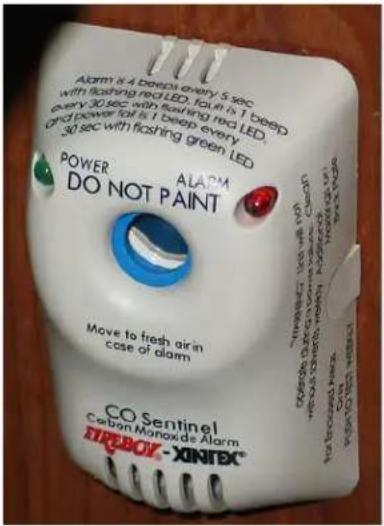
Use the following procedure monthly or when leaving the vessel for extended periods. Nor mal maintenance should include fre equent checking for the green power light glowing with the warning indicator and audible horn off. The detector should be returned to the manufacturer for recertification each year.
CO Sentinel Carbon Monoxide Alarm
TO REMOVE CIRCUIT BOARD FROM BASE PLATE
FOLLOW THESE TWO STEPS:
-
Push "locking pins" outward and lift bottom portion of board toward you.
-
Holding the board with one hand, pull to remove the connector(s).
TO RE-INSTALL: Reverse this procedure.
TO INSTALL CIRCUIT BOARD INTO BASE PLATE, FOLLOW THESE TWO STEPS:
-
Insert top of board (with 45° angles) under holding tabs on base plate.
-
Gently lower bottom until board "snaps" into locking pins.


DOOR-CABIN ENTRY
Periodically clean the lower door tracks since debris can clog the track resulting in a door that may jerk instead of slide to open or close. Use a vacuum or a soft damp cloth.
Lubicate the latch and lock mechanism sparingly with a powdered graphite available at the big box stores. Stick the tube in the key hole and squirt in the graphite. Wipe off any excess with a soft cloth.
ELECTRONICS-GARMIN
General Maintenance
Since there are no user-serviceable parts on electronic products they should be serviced only by specific marine electronic certified factory technicians.
Some products generate high voltages, and so never handle the cables/connectors when power is being applied to the equipment.
When powered up, all electrical equipment produces electromagnetic fields. These can cause adjacent pieces of equipment to interact with one another, with a consequent adverse effect on operation. In order to minimize these effects and enable you to get the best possible performance from your electronic equipment, guidelines are given in the installation instructions, to enable you to ensure minimum interaction between different items of equipment, i.e. ensure optimum Electromagnetic Compatibility (EMC).
In some installations, it may not be possible to prevent the equipment from being affected by external influences. In general this will not damage the equipment but it can lead to spurious resetting action, or momentarily may result in faulty operation.
Certain atmospheric conditions may cause condensation to form on the instrument window. This will not harm the instrument and can be cleared up by increasing the illumination setting.
Periodically clean any electronic display screens with a soft damp cloth. Do not use any harsh chemicals, solvents or abrasive materials to clean the instrument.
Note: For detailed information on each component refer to your electronics owner's manuals in the owner's information packet. Also, the vendor can be found on-line or phone your closest Regal yacht dealer.
ELECTRONICS-VHF RADIO

If installed the VHF marine radio has been constructed to be virtually maintenance free. With a little attention to a few basic care points, the unit should provide years of service.
- Although the unit is waterproof by design, keep it as dry as possible. When cleaning the cockpit, never use a direct water nozzle on the unit.
- Clean the exterior with a soft, non-abrasive cloth.
- Do not use any solvents or other chemicals for cleaning the VHF radio.
- Periodically inspect the radio case, electrical wiring and antenna for physical damage.
Note: For further information refer to your electronics owner's manuals in the owner's information packet. Also, the vendor can be contacted on-line or phone your closest Regal dealer.
FIRE EXTINGUISHING SYSTEM-AUTOMATIC

Inspect the pressure gauge before each outing. The illustration shows the ready and discharge condition of the actuator. Remove and weigh the unit (minus brackets) every 6 months on an accurate scale (Do
not use any hand held scales). If weight is below that shown on the unit nameplate, it must be removed from service immediately. If leakage is suspected, brush liquid soap on all points of possible leaks, or submerge entire unit in clear fresh water and watch carefully for 5 or 10 minutes.
Leaks will appear as tiny bubbles. If leakage is found return to the factory immediately for repair or replacement. Remember the two most important requirements to assure full charge and reliability of your Fireboy system are:
- Visual inspection of the gauge and the actuator to determine if it has actuated.
- Weighing to determine the true contents of the agent in the system.
All models from 75 cubic feet are rechargable. Recharging is possible only if the unit has leaked out verses losing agent due to a fire.
Should the indicator light fail to come ON when the ignition key is ON, first check the pressure gauge and actuator to see if the unit has discharged. If not check the breaker.
Next, using a continuity tester, check the electrical pressure switch on the system bottle itself. Pull the molded rubber connector off by pulling straight away from the manifold, and place the probes of the continuity tester directly on the spade connectors. This pressure switch should show a closed circuit.

Next, check the continuity of the entire wiring circuit. The indicator lamp is an LED (light emitting diode) and cannot be tested with a continuity tester.
A simple method to test LED'S is to remove the lamp and touch the red wire to the + terminal and the black wire to the - terminal of an ordinary 9 volt battery. Should the indicator lamp be faulty, replacement lamps are available from Fireboy.
Should the continuity of the pressure switch indicate an open circuit, the system will have to be returned to the factory for either replacement or repair.
FUEL SYSTEM
Periodically (at least twice annually) inspect the fuel tank components for loose clamps at the vent, fill, return and feed locations. Examine each hose for signs of deterioration and leakage. Check the fuel sender for loose fasteners and leaks at all areas of contact. Also, inspect the fuel tank for signs of leakage or abrasion. Tighten all components as needed.
Note: Do a visual inspection before each cruise. Again, include the high pressure diesel engine fuel hose components along with the diesel fuel fl iters both in-line and connected to the engine. Also, with dual fuel tanks check the diesel fuel transfer pump connections.
GENERATOR OPTION-TYPICAL

Read and become familiar with the generator owner's manual. It provides a variety of operational, safety and troubleshooting information. The output voltage under a full load can be easily periodically checked by observing the AC voltage meter found on the AC/DC panel. The output voltage should be between 110 -120 volts AC (60 hertz-US), and 220- 240 volts AC at (50 hertz- International). Voltages outside these specifications could indicate a generator malfunction. Make sure all fluid levels are checked before starting the generator. The generator seacock handle must be in-line with the seacock and the sea water strainer must be free from debris.
The generator features an automatic shut down system of sensors controlling high exhaust temperature, high water, low oil pressure, and high RPM. If one of these sensors engages, the generator will shut down. The source of the problem then needs to be determined. Use the owner's manual troubleshooting section as a reference.
There is a fuel fi lter in the system that periodically needs checking and cleaning. Refer to the owner's manual. Disconnect the battery cables before doing any generator maintenance. Inspect and clean the flame arrestor/air intake periodically by blowing off with compressed air. Inspect all fuel system fittings for leakage periodically. Be sure proper ventilation is present when servicing the fuel system components. Inspect all water and heat exchanger fittings periodically for leaks. Repair or replace components as needed. Be sure the generator is completely cold before performing any maintenance on the water system due to possible hot water and or antifreeze filled components. Be sure to catch and dispose of any antifreeze coolant properly. Refer to the generator owner's manual regarding antifreeze recommendations for type and mixture concentrations.
There is a zinc anode located in the raw water part of the heat exchanger. Replace if 50% erroded. It is self-sacrificing thereby reducing the effects of electrolysis to the generator water system.
At the longest span, push down at the center. You should generate a movement of 3/8 to 1/2 inch. Refer to the generator manual for more information.
When refilling the crankcase with oil follow the specifications given in the owner's manual. Dispose of used oil in an environmentally friendly manner. Following are selected detailed maintenance functions on the diesel generator. Refer to the generator owner's manual for more information.
Note: Read and understand the following safety warnings before performing any maintenance procedures.

WARNING
AVOID SERIOUS INJURY FROM ACCIDENTAL GENERATOR STARTING! DISCONNECT THE BATTERY CABLES BEFORE WORKING ON THE GENERATOR.

WARNING
AVOID SERIOUS INJURY FROM A HOT GENERATOR AND EXHAUST SYSTEM. DO NOT WORK ON GENERATOR UNTIL THE UNIT COOLS.

WARNING
AVOID SERIOUS INJURY FROM ROTATING PARTS! OPERATE THE GENERATOR ONLY WHEN ALL SCREENS, COVERS & GUARDS ARE IN PLACE.
| DATE RUN | OPERATING HOURS | SERVICE RECORD | ||
| HOURS RUN | TOTAL HOURS | SERVICE DATE | SERVICE | |
GROUND FAULT OUTLET:
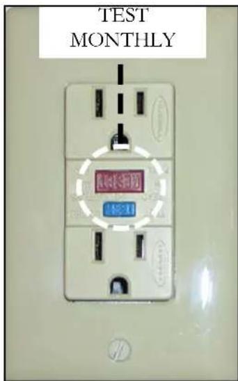
The GFIC (Ground Fault Interrupter Circuit, GFIC abbreviated) outlets should be tested monthly. To test the unit, depress the reset button. Then press the test button. The reset button should pop out.
If it does not, contact a qualified electrician or marine professional to replace the device.
Refer to Chapter 4 where it explains the system operation and shows the circuitry throughout the vessel. The GFIC is
normally located at the beginning of a circuit so that all receptacles further down the circuit are protected. That could be a reason why several components plugged into outlets will not work when a GFIC is not functioning. The device trips between 4 and 6 mA's.
HEATER-HOT WATER
A. The most important maintenance factor with the hot water heater is that it is winterized with Winterban (RV anti-freeze; alcohol style) in freezing climates. Use the water heater drain valve to vacate water from the tank. The water will automatically drain into the shower sump pump and then will be sent overboard. Make sure the water heater breaker is turned off before any winterization is started to prevent the element from being burned out.
B. If the system is constantly being used in warmer climates it is a good idea to periodically drain the hot water valve for 30 seconds or so to eliminate any scale that has built up inside the hot water heater. Turn the breaker off just as a precaution.
C. The hot water heater and heat exchanger parts are made of aluminum. If engine flushing is required by the manufacturer be sure to disconnect the heat exchanger from the system temporarily.. The caustic chemicals will damage the hot water heater aluminum parts. Re-plumb the heat exchanger back after engine flushing.
D. Test the T& P valve periodically to make sure it works properly. Its purpose is to let off excess water vapor (steam) if the thermostat should stick and a critical temperature situation develops within the tank. Pull on the valve to test it. The water will vacate to the shower sump pump and then overboard.
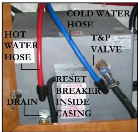
HIGH WATER ALARM
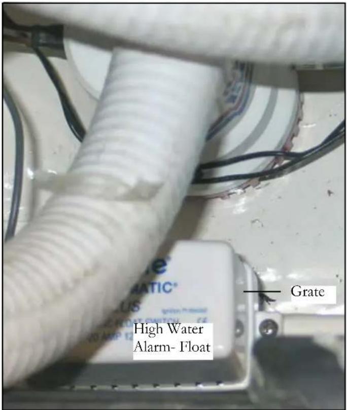
The high water alarm float is located in the engine room. Periodic maintenance consists of visually inspecting the float grate cover for debris and removing any accumulation.

WARNING
TO PREVENT BODILY INJURY OR DEATH NEVER USE AUTO ANTIFREEZE IN A MARINE WATER SYSTEM OR ANY OF ITS PARTS. AUTO ANTI-FREEZE IS HIGHLY TOXIC AND POISONOUS TO THE HUMAN BODY.
HORN (TYPICAL AIR OPERATED)
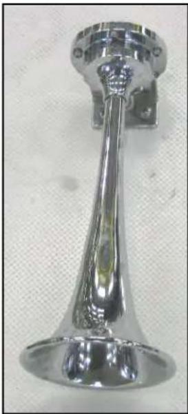
coverage.
The typical air horn features an air pump. The horn emits a sound that can be heard much louder than the typical electrical horn. This extra distance capability can be useful in ship to ship crossings especially when foul weather is present.
Check the horn assembly for debris and insect nests periodically. Use an auto grade chrome cleaner on the horn assembly at least annually. After each cruise, rinse the horn assembly with fresh water.
Check the fasteners for tightness annually along with the deck sealant for complete sealing
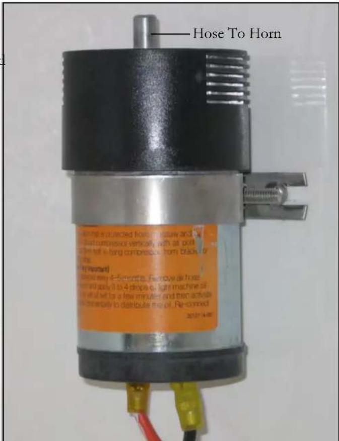
Typical Air Horn Pump
Normally the air horn pump requires no maintenance. If problems exist contact your closest Regal dealer.
PLUMBING CONNECTORS
Plumbing connections to the red and blue fresh water lines require special instructions when they are to be removed or replaced. Be sure to turn off the water for that circuit at the manifold before starting any plumbing repairs.
To reinstall a plumbing connection to a water line make sure the line is cut off square and the end is smooth. This will aid in ensuring a leakproof connection.
-
To remove a tee, 90 degree, or straight connector fi tting fi rst remove the cap on the end of the fi tting by using a slotted screwdriver. Insert the screwdriver in the cap slot and turn 90 degrees. Cap will release from the fi tting.
-
Install the cap on the supply line. You may need to use a slotted screwdriver to remove the cap from a new fl tting.
-
Simply push the fi tting on to the supply line until pressure is felt. This ensures it is completely in the fi tting.
-
Push the cap on the collar until it snaps in place. Turn on the water pressure and check for leaks.
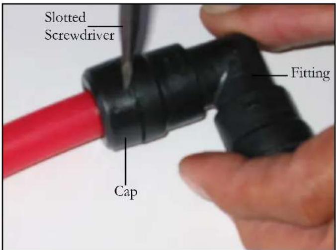
Note: With the connector in place, a movement between the line and connector is normal.
- Push the connector and collar together. Hold the collar next to the connector with your finger. Pull and the connector/collar will release itself from the water line.

PRESSURE PUMP-FRESH WATER
The fresh water system in general requires very little maintenance.
- See the equipment operation chapter defining the recommended seasonal disinfection procedure.
- The fresh water filter needs to be cleaned periodically. Simply remove the hose clamp and unscrew the fresh water filter to access the screen. Rinse the screen off to remove any foreign debris. Be sure to use tefl on tape on the pump fitting threads before installing the filter. Reinstall the components and check for leaks.
- Periodically check all fittings for leaks.
- In colder climates, use Winterban or its equivalent in all the fresh water system components after draining the system.
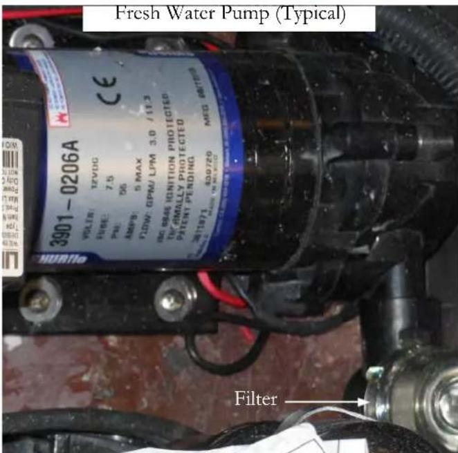
PUMP-OVERBOARD DISCHARGE

If your boat is equipped with an overboard discharge pump pay close attention to what materials are flushed through the waste system as it could become clogged. Do not pump garbage, rags, or sanitary napkins through the overboard discharge pump (macerator). Flush the waste tank and pump with fresh water with each pump out. Do not run the pump dry or for extended periods of time since the impeller can be damaged.
Pump the waste system out at decommissioning time and rinse fresh water through the entire system periodically to keep the hoses clean of debris especially the pump out hose.
SHOWER SUMP PUMP-TYPICAL
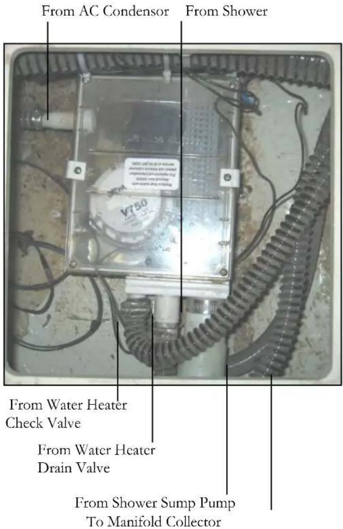
The shower sump pump shown above is used to collect gray water waste from the sinks or the shower itself. After the liquid reaches a designated height, the sump pump energizes through a fl oat switch and exits waste to a manifold then overboard. This system helps to protect our water supply by not dumping used water overboard. Periodically check the sump pump grate for debris such as hair and soap build up. Check to make sure the automatic fl oat operates freely at all times. Also, clean out the box with a bleach/water solution as needed to kill bacteria. You can back flush using the bleach/water procedure.
STEREO/DVD PLAYER/TELEVISION
Since most of the same cleaning and maintenance tips overlap on these entertainment components, they will be grouped together.
-
To clean the CD slots in stereos, DVD players use a dry or slightly water moistened swab to remove any buildup of debris. This monthly procedure will assist in preventing the CD discs from being scratched.
-
To clean the faceplates of the various units use a dry soft cloth. If the faceplate is stained badly, use a moist cloth with a neutral cleaner. Do not use harsh, caustic or alcohol based chemicals to keep the letters from coming off the faceplate. Do not use silicone spray or WD-40 since they could damage mechanical parts.
-
If these units will not play CD's properly it they may have developed condensation. Wait 1 hour and retry.
-
Keep all remote controls out of extreme heat and high moisture environments. Change batteries often for best operation.
-
Periodically check CD discs for scratched and dirty ones. Clean the dirty ones with a cleaning kit which can be purchased at most electronic stores.
-
With fl at screen televisions, do not attempt to service the unit yourself since high voltage exists.
-
To clean the fl at screen display, dampen a soft cloth with water or a mild detergent. The best cleaner is a screen cleaning tissue specifically designed for antistatic coating. Never use fl ammable cleaning materials or glass cleaners with ammonia since they attack the television screen surface.
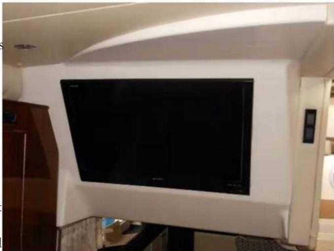
TELEVISION FLAT SCREEN MONITOR
These cleaning recommendations cover LED TV's that may be installed in the main cabin, forward and master staterooms and cockpit. Regular cleaning of the these units will help extend their life. Turn the power off at the breaker before you begin any cleaning procedure.
Cleaning The Screen
Wet a soft cloth in a mixture of warm water and fabric softener or dish washing detergent. Wring out the cloth until it is almost dry. Wipe the screen to remove dust and debris.
Remove any excess water from the screen and let the screen air-dry before you activate the television breaker and turn the unit on.
Cleaning The Cabinet
Use a soft, lint-free cloth to clean the cabinet off. Again, do not use a wet cloth.
NOTICE
WHEN LEFT FOR EXTENDED PERIODS TURN THE TELEVISION BREAKER TO THE OFF POSITION TO HELP PREVENT POWER SURGES OR LIGHTNING DAMAGE.
NOTICE
TO PROTECT THE INTERNAL TELEVISION COMPONENTS OF THE TELEVISION REMOVE THE TELEVISION FROM THE VESSEL IN FREEZING CLIMATES. CONTACT YOUR REGAL DEALER FOR TECHNICAL SERVICE.
TRIM TABS
Trim tabs are located on the outer edges of your yacht transom below the swim platform. All mechanical and electrical connections should be periodically checked for tightness, corrosion, and chafing. If a malfunctioning tab is suspected, run each tab in and out while someone looks at each tab to make sure it is moving up and down the proper distance. Replace any zinc anodes mounted on trib tabs when at one half their life as determined by size. Check anodes twice a month.
Check the hydraulic power unit fluid (HPU) level. The pump is located in the bilge (sump) close to the transom. To refi ll, remove the lexan cover and fi ller plug. Fill with any type automatic transmission fluid (ATF). The fluid level should be 2" from the reservoir bottom.
The trim tabs may be painted for corrosion protection.
Do not paint the anodes as they protect the tabs from galvanic corrosion.

UNDERWATER HARDWARE-SEACOCKS & STRAINERS
Inspect the thru-hull seacocks before each outing. Make sure the connections between the output hose and the valve are tight. Look for water leaks around the area where the valve and hull meet.
Every 30 days open and close each thru-hull valve several times. This will guard against the valve seizing in the open or closed position. Also, make sure the valve handle is tightly fastened. Secure any loose valve handles.

Before servicing the sea water strainer make sure the appropriate seacock has been closed to prevent water from entering the boat. If possible blow out the strainer basket with compressed air or use a metal type brush to remove any accumulated material from the screening material. Check all parts for wear and possible leaks including any O ring surfaces. Lubricate O ring with waterproof product available at many box or pool stores. Do not overtighten the strainer hold down fastener which could cause strainer body damage especially on the newer plastic versions. Use original replacement marine parts only. After all parts are reassembled open the seacock and check for leaks.
Notice there is a drain hole in the bottom of the strainer body.
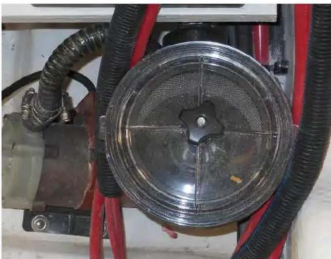
TYPICAL STRAINER
TOILET-VACUUM DESIGN
Vacuum style toilet systems need to be cleaned periodically for maximum sanitation and operational efficiency. Clean the bowl with a cleaner such as Bon Ami which will not abrade the toilet bowl lining. Do not use chlorine solvents or caustic chemicals such as drain openers because the various system seals may be damaged. Use the following procedure monthly or when leaving the vessel for extended periods.
-
Fill bowl with water.
-
Add 1 cup of biodegradable powdered laundry detergent.
-
Flush toilet by pressing the pedal for about 2 minutes. Release foot pedal to close flush ball.
-
Most marinas offer a service that uses a vacuum hose connected to the deck waste fi tting that pulls the waste from the tank. We suggest using a hose after the process and shoot a few bursts of fresh water down the waste fi tting at the deck. This helps the residue left from the pump-out process from building up in the waste hose.
If an odor is apparent from the system try the following:
-
Clean the system out using the above procedure.
-
Check to see that the vent from the holding tank to thru-hull fi tting is not clogged.
-
Periodically add the correct holding tank deodorant either Secure or Sealand liquid.
-
Annually replace the in-line vent wase fi lter normally located in the bilge. This fi lter can be ordered from a Regal dealer or your local marine supply store.
-
Refer to the toilet manual for further information.
THRUSTER-BOW
Refer to your thruster operator's manual for more detailed information on maintenance schedules and procedures.
Galvanic Test: Ohm readings with battery disconnected between the positive stud, and the motor case must show no continuity or the unit will experience galvanic corrosion.
Periodically check the propeller hardware paying close attention to the anode. If anode is 50% erroded replace it. Assemble propeller in this order; large washer, propeller, anode, small washer and nyloc nut. Torque propeller nut to 7.4 ft. lbs. Make sure the propeller does not touch tunnel.
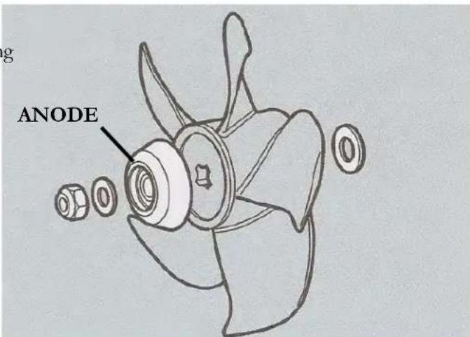
CLEANING STRETCH HOSE
The stretch hose on occasion has a tendency to get clogged especially if you have pets on board. To clean the hose:
-
Lift the hose up at both ends and dispense some liquid detergent into both ends.
-
With a garden hose, holding both ends still up, fill 3/4 with water.
-
Shake hose up and down, let detergent loosen the dirt and clogged debris.
-
Stretch the hose as far as you can (2 people required) and wash the dirt out with the full pressure of a garden hose. Repeat as necessary.
-
Hang hose up on one end. Let hose drain and dry completely.
WINDLASS
The typical windlass needs periodic maintenance to keep it in top running condition. Every 6 months the manufacturer recommends that the unit be disassembled and all the above deck parts be washed down with fresh water. Lightly oil (SAE 10) the seal, shaft, cone clutch and spline. Ensure that the base, below the gipsy, is cleaned well and the sealing ring is checked. Grease the threads on the chain pipe cover and stripper screws before re-assembly. The bearing is self lubricating and should not require servicing.
Below the deck check regularly the condition of the motor/gear box and terminals and re-apply grease when necessary. The motor/gear box is two part epoxy painted to protect it against corrosion as it is constructed of steel and lives in the harshest environment on your craft. If corrosion on the motor is evident, clean and repaint with marine grade oil based enamel paint.
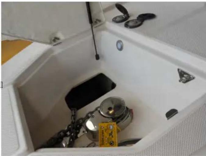
Note: Refer to the windlass operator's manual for additional and more detailed maintenance information.

WARNING
TO PREVENT BODILY INJURY REMOVE THE CHAIN FROM WINDLASS BEFORE PERFORMING MAINTENANCE.
Troubleshooting
DIAGNOSTIC CHARTS
The following diagnostic charts will assist you in identifying minor electrical, electronic, fuel, and mechanical problems. associated with selected standard and/or optional components. A portion of the items listed require technical training and tools. Additional up-to-date information is available in the various operation manuals as select items and their troubleshooting techniques may change since the printing of this manual and/or are too numerous to cover in this manual such as electronic components.
Contact your closest Regal dealer, marine professional or internet for further information.
Note: Many times the root cause of a problem can be found using a step by step process of elimination.

WARNING
AVOID BODILY INJURY AND DEATH! BEFORE PERFORMING ANY MAINTENANCE WORK TURN OFF THE BATTERY SWITCH AND REMOVE THE KEYS FROM THE IGNITION SWITCH.

CAUTION
TO AVOID BODILY INJURY! USE ONLY APPROVED MARINE REPLACEMENT PARTS.

CAUTION
TO AVOID BODILY INJURY! SOME EQUIPMENT CONTAINS HIGH VOLTAGE. USE CAUTION WHEN SERVICING ELECTRICAL COMPONENTS.
ELECTRICAL DIAGNOSTICS (AC)
| PROBLEM POSSIBLE | CAUSE POSSIBLE FIX | |
| No AC power Main shore power breakers tripped or in “off” position | Energize shore power inlet breakers | |
| Dock power in “off” position Activate dockside power | ||
| Shore power cord not connected Plug in shore power cord; twist to lock | ||
| Faulty connection Repair as needed | ||
| Main ELCI breaker tripped Repair as needed. Reset breaker. | ||
| Nusiance Tripping- Main ELCI Component causing excessive draw Repair/Replace part. Reset ELCI | ||
| No power to AC outlets and/or equipment | Main AC ship’s panel breakers tripped or in “off” position | Reset or activate main breakers |
| Shore power cord not connected Plug in shore power cord | ||
| GFCI tripped | Find cause of trip. Reset GFIC | |
| Main ship’s breaker continues to trip | Faulty main breaker | Contact yacht authorized dealer |
| Inadequate AC power with gen-set running | Electrical demand greater than electrical output | Turn off appropriate equipment breakers to lessen load |
| ELECTRICAL DIAGNOSTICS (DC) | ||
| PROBLEM POSSIBLE | CAUSE POSSIBLE FIX | |
| No DC (12 volt) power Battery switch | in “off” position Turn selector switch to “on” position, | |
| Weak or dead battery Charge or replace battery | ||
| Battery not charging (engine running) | Loose belt Tighten belt | |
| Faulty alternator Repair/replace alternator | ||
| Faulty volt meter Replace volt meter | ||
| Battery will not hold charge | Faulty or old battery | Replace battery; use exact replacement |
| 12 volt equipment not working | Equipment switch in “off” position | Switch to “on”position |
| Circuit breaker/fuse blown | Reset breaker. Replace fuse. | |
| Weak or dead battery Replace battery | ||
| Corroded connection | Eliminate corrosion | |
| Loose wire | Tighten connection | |
| Internal equipment short | Replace equipment component | |
ELECTRONICS-GENERAL
The Garmin electronic packages installed on your boat are very system specific when troubleshooting. Each package is very unique and we could not cover all the systems here. Therefore, refer to the vendor supplied operator's manual for specific troubleshooting information related to an individual electronic component.
In addition, helpful information is readily available on the internet at each vendor site. Information can be downloaded as needed with additional on-line contact and tech services available.
Also, contact your closest Regal dealer where you will find factory trained professionals to assist you in solving more technical electronic component issues.
| FRESH WATER DIAGNOSTIC CHART | ||
| PROBLEM POSSIBLE | CAUSE POSSIBLE FIX | |
| Air in water system Water tank empty | Fill water tank. With pump “on” | bleed air from lines until water flows without air. |
| Fresh water pump cycles on and off | Water system leak Locate & repair water leak. | |
| No water at sink faucet Breaker blown | n Reset breaker | |
| Water tank empty Refi ll water tank | ||
| Switch turned off Turn switch to “on” position | ||
| Blocked water filter; pinched line | Clear obstruction or straighten line; clean water filter | |
| Manifold valve turned off | Turn on manifold valve | |
| Loose or disconnected wire | Check wire connections | |
| Low water pressure | Defective fresh water pump | Replace water pump |
| Weak pressure at transom shower | Line pinched | Find/Repair pinched line |
| Water to pump. No output. | Faulty fresh water pump/pressure switch | Replace fresh water pump or pressure switch |
| Fresh water pump continues to cycle | Defective pump pressure switch | Replace pressure switch |
| INSTRUMENT DIAGNOSTIC CHART | ||
| PROBLEM POSSIBLE | CAUSE POSSIBLE FIX | |
| No reading on gauge or gauge reads wrong | Faulty gauge Replace gauge | |
| Wiring to gauge faulty Inspect/repair | wiring | |
| Faulty sender Replace sender | ||
| Gauge reads erratic Loose ground or | hot wire Repair/replace wire and/or connection | |
| PERFORMANCE DIAGNOSTICS | ||
| PROBLEM POSSIBLE | CAUSE POSSIBLE FIX | |
| Excessive vibration Material obstructing propeller Reverse engines to remove material | ||
| Poor performance Trim incorrect Adjust trim | ||
| Engine problem Call authorized Regal dealer | ||
| Engine speed/rpm is low Growth on | hull Hoist vessel; clean bottom | |
| Poor quality fuel | Call authorized Regal dealer | |
| Accumulation of bilge water | Check for leaks | |
| Trim tab in “up” position | Check trim tab functions/pump fluid levels | |
| REFRIGERATOR DIAGNOSTIC CHART | ||
| PROBLEM POSSIBLE | CAUSE POSSIBLE FIX | |
| Refrigerator not cold Compressor will | not start Turn breaker on at the main ship's service panel | |
| Thermostat set too high or on/off switch is in the off position | Reset thermostat or activate on-off switch | |
| Compressor starts but does not cool fridge | Contact repair professional | |
| Door latch not closing or door seal not seated | Adjust latch or replace seal | |
| Condensor dirty Remove fridge/clean coils with brush or vacuum | ||
| Not running on DC Check for defective thermostat or converter, low battery | Relace thermostat, converter or battery | |
| Not running on AC | Inadequate input voltage | Make sure proper voltage exists on ship's main AC panel. |
STEREO DIAGNOSTIC CHART
TROUBLESHOOTING
| Problem | Solution |
| General | |
| The unit does not respond to key presses. | Reset the unit by pressing the Reset button inside the control panel door.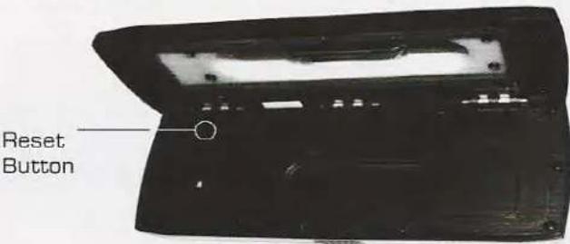 |
| What is the best way to prevent corrosion on my 700 Series chrome finish? | As with all products exposed to the harsh marine environment, a little care will help to preserve the finish. FUSION recommends that you clean any salt water and/or salt residue from the front panel with a damp cloth soaked in fresh water. |
| Problem | Solution |
| SiriusXM | |
| When I press the tuner source button the SiriusXM screen is not displayed. | Ensure you have the MS700i Tuner region set to 'USA'. Press Menu > Settings > Tuner region > and select 'USA'.• Ensure the SiriusXM module is plugged into the MS700i.• Unplug the SiriusXM module and check the pins in the SiriusXM plug are not damaged. |
| SiriusXM message: 'Check Tuner' | • Ensure the SiriusXM module is plugged into the MS700i.• Ensure the SiriusXM cable has not been damaged. |
| SiriusXM message: 'Check Antenna' | • Ensure the antenna is plugged into the SiriusXM Tuner module.• Ensure the antenna is not damaged.• Ensure the antenna cable has not been damaged |
| SiriusXM message: 'No Signal'. | • Ensure the antenna is not damaged.• Ensure the antenna has a clear view of the sky and is not obscured.• Ensure the antenna cable has not been damaged |
| SiriusXM message: 'Channel xx Not Available' | A SiriusXM message informing you that the current channel is unavailable. Possible causes are SiriusXM has removed the channel or your SiriusXM subscription has changed.• Contact SiriusXM to update your subscription.• Online: Go to www.siriusxm.com/subscriptions• Phone: Call 1-866-635-2349 |
STEREO DIAGNOSTIC CHART
| SiriusXMmessage:'Channel xxUnsubscribed' | Contact SiriusXM to update your subscription.Online: Go to www.siriusxm.com/subscriptionsPhone: Call 1-866-635-2349 |
| SiriusXMmessage:'SubscriptionUpdated' | A SiriusXM message informing you that you have either been granted access to or unsubscribed from various channels.For more information about your subscription:Online: Go to www.siriusxm.com/subscriptionsPhone: Call 1-866-635-2349 |
| Problem | Solution |
| iPod | |
| Why does my FUSION Head unit keep locking up when connected to my iPod/iPhone? | If you are experiencing software lock-ups or your unit freezes:Reset the Head unit by pressing the reset button inside the face plate.Reset your iPod/iPhone (see Apple website from model-specific information). This should resume normal operation.Make sure you have the latest version of iTunes and the latest operating software in your iPod/iPhone. It is important to update software when Apple releases new versions. If you are connected via a dock, ensure you are using the correct sleeve and the connection to the Head unit is secure. |
| Will my iPod/iPhone connect to my FUSION product if the battery is flat? | No. It will take a number of minutes for the Apple product to get a minimum level of charge before it can connect and become operational. Please connect and wait for the unit to initialise. |
| My Apple Device has gone into thermal protection | Caution: The internal dock temperature of the MS-IP700i will be slightly higher than the ambient temperature outside the head unit. Should your Apple iPhone or iTouch shut down due to exceeding the operating temperature please carefully remove it from the MS-IP700i and allow it to cool down before using again. Using your Apple device in a low charged state will increase the heat generated whilst it is charging. For more information relating to this please follow the Apple support web site link below.http://support.apple.com/kb/ht2101 |
STEREO DIAGNOSTIC CHART
| My iPod/iPhone will not connect to the Head unit while in the dock. | If your Head unit displays "Not Connected" while using iPod as input source:Check that you are using the correct sleeve combination. If you have the incorrect sleeve combination this could prevent the iPod connector from mating correctly. It could also damage the connector in the dock or your iPod/iPhone itself. If you are uncertain which iPod model you have, go to http://www.apple.com/support/ to get the correct model information for your iPod and sleeve.If you are still unable to connect once you know for certain you have the correct iPod/iPhone-sleeve combination:Ensure that you have the latest version of operating software installed in your iPod/iPhone and the latest iTunes version. To do this, connect your iPod/iPhone to iTunes and it will check and, if necessary, prompt you to download the latest version.If you are still unable to connect once you have confirmed that you have the latest software or you have updated your iPod/iPhone:Reset the iPod/iPhone (see the user manual for your Apple product) and also reset the Head unit (see FUSION user manual).If you are still unable to connect:Contact your FUSION dealer or contact FUSION via the tech email on the FUSION website. |
| Problem | Solution |
| Wireless Remote App for iPad and iPhone | |
| My FUSION-Link Wireless application displays "No stereo available" | The first thing to check is that you are connected to the correct wireless network for the 700 Series.Once you have confirmed this close the App on the device and restart it (consult the manufacturers website for instructions on restarting). If this fails check that you have a valid IP address on the 700 Series and follow the instructions in the below tech support item |
| My FUSION-Link Wireless remote application will not connect to my 700 Series stereo | The first thing to check is that the 700 Series is displaying a valid IP address on the about screen. Select the settings menu then about to confirm. If the display is "IPNone" the router is either not a compatible DHCP product or not configured correctly. If the IP address starts with the prefix 169, it is not valid, this is a default address when the router is not sending a DHCP generated IP address or is configured incorrectly. Please review the Router's instruction manual or contact the manufacturers website for technical help. |
TACHOMETER-ELECTRONIC DIESEL
Troubleshooting
Symptom recognition is the first step in effective instrumentation troubleshooting. Tachometers usually exhibit the following symptoms: a) dead, b) pegged, c) erratic, d) reading high, e) reading low, and f) sticky. More thorough tests of all tach's can be conducted using the Faria® Instrumentation Tester. (See Appendix III).
Symptom:
A. Dead - This is usually caused by: a) No power applied, b) No signal supplied, or c) Tach damaged by electrical transients caused by disconnecting the battery with the engine running.
-
Check to see if power is applied to tach by switching the instrument power supply switch on and off. As power is applied, the pointer should jump slightly. If it does not, check to see that the wires are installed on the correct terminals and that 12 volts are actually applied to the terminals themselves.
-
If tach indicates that power is applied, check for the presence of a signal on the signal terminal. Measure the signal between the signal and ground terminals. This should read in excess of 2 volts DC.
-
If power and signal are present, then it is possible that the tach has been damaged by electrical transients. See the enclosed technical bulletin for details.
B. Pegged - This condition occurs on tach's with internal mechanical pointer stops. It is caused by removing power from the tach while it is running in excess of mid-scale RPM's or by the switch on back of the tach being in between positions. When power is re-applied, the tach pointer attempts to go clockwise to zero but cannot because the internal stop is in the way. Read "Marine Instrumentation Facts" for details on how to correct this condition.
C. Erratic - This symptom is caused 99% of the time by an intermittent connection between the wire and the ring or spade connector. Often the wire's insulation is pushed into the crimp area and crimped. The center conductor casually touches the connector allowing the tach to work most of the time but causing a nightmare for the technician. Electrical noise also can cause erratic readings. See "Reading High" for further information.
D. Reading High - This is usually caused by the switch on the back of the tach being in the wrong position. If the number of cylinders or alternator poles selected by the switch is too low, the tach will read high. If a variable alternator or mag pick-up tach is being used, then further calibration may be necessary, as this calibration is done by the end user. See 'Calibration'. Excessive electrical noise may also cause the tach to read high. These noise spikes are counted by the tach as engine RPM's. The wire affected by the noise can be identified by connecting one wire at a time to the tachometer directly from the battery or the signal source on the engine.
E. Reading Low - If the number of cylinders or alternator poles selected by the switch is too high, then the tach will read low. If a variable ratio or mag pick-up tachometer is being used, further calibration by the end user may be necessary. See 'Calibration'.
F. Sticky - If the tach appears to "stick" during operation, slightly loosen nuts holding backclamp and check operation. If tach now operates properly and is not loose in panel, tach now should provide suitable service. If tach continues to stick during operation -- replace tach.
TACHOMETER-ELECTRONIC DIESEL
Calibration
Set up a calibrated “shop tach” or “strobe tach” to monitor the engine’s true RPM. Start the engine and (after an appropriate warm-up period and with the shift in neutral) increase it’s speed to the boat’s normal cruising RPM read on the shop tach. Set the coarse adjustment switch to the proper position described on it’s label. Remove the stop-plug or paper label corner (at the 8-o’clock position on the rear of the case for most) and insert a 5/64” Allen wrench into the “fine adjustment” trimpot, rotating it CW or CCW as necessary to indicate the true RPM.
| TELEVISION DIAGNOSTIC CHART | ||
| PROBLEM POSSIBLE | CAUSE POSSIBLE FIX | |
| Screen is black. Power indicator is off. | TV breaker not activated Activate TV | breaker on ship's main service AC panel. |
| TV and/or DVD not turned on. Activate TV or DVD player. | ||
| TV signal weak. TV antenna breaker | not activated or wrong antenna breaker in use. | Activate TV antenna breaker. Check antenna switch for proper signal button. |
| Image too light or dark. Brightness or contrast improperly adjusted. | Readjust brightness or contrast to owner's manual specifi cations. | |
| Horizontal bars appear to flicker, jitter, or shimmer on the image. | Fine function not adjusted properly. | Adjust fine function to owners manual specifi cations. |
| Vertical bars appear to flicker, jitter or shimmer on the image. | Coarse function not adjusted properly. | Adjust coarse function. Then adjust fine function. |
| Screen is blank and power indicator light is steady amber or blinks every 1/2 or 1 second. | Power management system being used. | See power saver in owner's manual. |
| Image not centered on screen | Horizontal or vertical adjustments off. | Readjust horizontal or vertical controls. |
TOILET (TECHMA) DIAGNOSTIC CHART
| PROBLEM CAUSE ACTION/SOLUTION | ||
| Toilet does not flush or flush performance is poor | Waste tank is full (tank indicator light on wall switch is RED)Clog at pump inletSolid object in maceratorLow voltage | Empty waste tank before continuing to use toilet. Override full tank lock-out may cause waste tank to overflowClear clogCall Tecma at (800-521-3032)Check for no more than 10% decrease in voltage when macerator is running. If voltage decreases more than this there may be wiring problem |
| Water does not enter bowl during flush or water add cycle | Water supply line kinked or not connectedNo power to water pumpWater supply has been truned offElectronic control problem | Check that supply line is properly connected to fresh water supply.Check for kinks in water supply lineCheck that circuit breaker has not tripped, check all pump electrical connectorsCheck water supply valve at manifoldCall Tecma at (800-521-3032) |
| Water livel in bowl has changed after flush | Flush refill mode has been changed | Reprogram flush refill mode; see Techma owner's manual |
| Water continues dripping briefly into bowl after flush cycle is complete | Toilet is installed below water line with vacuum breaker in water supply line | Normal operation; if only a small amount drips from the nozzle |
| Bowl drains dry after flush | Water is siphoning out of the bowl | Discharge hose from macerator pump bent. Straighten hose |
| Wall switch does not appear to light up or does not stay lit | No power to toiletWall switch not properly connected to toiletWall switch has entered sleep mode | Check that breaker is not tripped.Check electrical connectors are matchedEnsure wall switch electrical connector is fully engaged at controllerWall switch enters sleep mode after 8 hours of continuous inactivity but remains functional. No action needed |
| Wall switch electronics problem | Call Tecma at (800-521-3032) | |
| Toilet is inoperative and there is no lighting in the wall switch | No power to toilet | Check that breaker is not tripped.Ensure all electrical connectors are matched. Call Tecma. |
THRUSTER-BOW
| Fault • Thrust in wrong direction? | Action • Change contactor wires on motor solenoid (See section 2.1). |
| Fault • Fuse keeps blowing? | Action • Wrong fuse fitted - check rating and replace. • Propeller restricted or jammed causing excessive load on motor - check and clear. Check that propeller washer is fitted see Section 6. |
| Fault • Control Panel does not illuminate? | Check • Power - Hold for 1 second. • Battery is connected. • Main switch ON, check fuse. • Control loom connections. • Long operation has tripped thermal switch. Wait 20 minutes for motor to cool and reset. DO NOT attempt to cool motor by any other means. |
| Fault • Control panel illuminates but no thrust? | Action • Are batteries charged? • Check main motor connections are tight. |
| Fault • Poor thrust or thrust in one direction only?? | Action • Batteries not large enough or charged, cables not recommended size. Voltage at motor when running should be a minimum 10 V for 12 V and 21 V for 24 V units. • Blockage in tunnel/propeller jammed with debris, switch off main power, inspect and clear. • Propeller washers fitted wrong. See Sec.1.6 • Check motor brush springs are located properly, brushes should have good contact with the commutator. |
| Fault • 140TT and 185TT ONLY - Motor turns but no drive? | Action • DO NOT continue to run thruster. • Shear pin broken, remove 4 motor bolts, see Sec. 4.2, drive out old pin and replace with new pin. • Propeller blades broken. Replace with new. |
| Fault • Thruster noisy and vibrating? | Action • Check propeller is not touching the tunnel wall. • 140 - 185 models: Check hub height is correct, see section 7. |
VACUUM CLEANING SYSTEM
If The Motor Stops Suddenly:
-
The most common cause is a clogged hose. Try to unclog the hose with a long stick or by shaking the hose until the clogged debris clears.
-
The bag is overfilled and fine dust has clogged the bag.
-
The vacuum cleaning tools are clogged.
-
The motor (exhaust) filter is dirty and should be cleaned or replaced.
-
Ensure that the area around the main unit is free of clutter to provide proper amount air to the unit. This will help prevent the unit from shutting down.
TYPICAL WINDLASS
![graph TD Q1["Does the windlass motor operate?"] --> Q2["Does the gypsy rotate?"] Q2 --> Q3["Safety switch on? (If fitted)"] Q3 --> Q5["Circuit breaker reset?"] Q5 --> Q7["Check 3 Amp switch protection fuse OK (If fitted)"] Q7 --> Q8["Switch connections correctly fitted"] Q8 --> Q9["Battery power OK"…](/content/2026/05/1030542/images/4a1a70594d630a0ceb3f3df3f36c32622561543f41cdb9ce18cf05d549de28ff.jpg)
Storage & Winterization
NOTICE
YOUR WARRANTY DOES NOT COVER DAMAGE TO YOUR BOAT IF IT IS NOT PROPERLY STORED AND WINTERIZED. CHECK WITH A REGAL DEALER OR MARINE PROFESSIONAL ABOUT WINTERIZATION PROCEDURES.
INTRODUCTION
Storage procedures are outlined in this chapter. These are general guidelines to follow in colder climates. Be sure to familiarize yourself with all relevant information in the owner's packet.
NOTICE
REMOVE ALL BATTERIES WHEN VESSEL IS STORED FOR EXTENDED PERIODS.
Special winterization procedures are necessary for the boat equipment and systems. Use the enclosed checklists to help you identify areas of concern and maintenance. These lists cover land stored boats either inside or outside.
All in all, it is best to contact your closest Regal dealer or marine professional for winterization information. They possess the advanced service know how needed to tackle the more complex yacht systems.
WARNING
EXPLOSION, FIRE & POLLUTION HAZARD! DO NOT FILL FUEL TANK TO RATED CAPACITY. LEAVE ROOM FOR EXPANSION.
DECOMMISSIONING CHECKLIST
BOAT
☐ Check hull bottom for any fi berglass damage. Repair as needed.
□Apply a coat of wax to hull and deck surfaces.
☐ Pour a pint of 50/50 antifreeze into bilge pump.
☐ Remove batteries. Trickle charge over extended periods. Do not set batteries on cement. Use wood blocks.
□Remove all loose gear from boat such as life jackets, etc. Inspect and store in cool, dry environment.
☐Remove drain plug. Clean drain plug hole of debris as needed. Enclose drain plug in plastic bag and tie to steering wheel.
☐ Drain the waste system per instructions in this chapter. Make sure bow is higher than stern to permit proper drainage.
□ Clean all upholstery and store so it breathes.
☐ Conduct a visual inspection to ensure boat is balanced properly. Bow should sit slightly up especially if outside.
☐ Cover boat with tarp. Tie down for wind protection if outside. Prop tarp up as needed to provide proper ventilation. Be sure not to cover up the fuel vents.
□ Drain the fresh water system per instructions in this chapter. (Ensure that the system has been disinfected)
☐ Send in appropriate equipment for calibration such as the automatic fire extinguisher canister or COdetectors.
□ Never use blocking to support the hull bottom as structural hull damage may occur to the vessel which is not covered under the warranty.
ENGINES
The propulsion systems on your boat are complex in scope. In colder climates, it is recommended that your Regal dealer winterize your boat's engines. Regal dealers have undergone extensive factory training covering the Regal product line. Also, the dealer is equipped with the parts and tools to perform a care free winterization procedure.
☐ Run engine. Pour a fuel stabilizer/conditioner in the fuel tank. Allow time for it to circulate through the fuel system. Top off fuel tanks to help prevent condensation.
Change all engine fluids as referenced in the engine manufacturer's owners manual.
Drain cooling and exhaust system or have a marine professional "pickle" the engine with antifreeze and rust preventative.
□ Spray all exterior parts with a rust preventative.
GENERAL NOTES ON ANTIFREEZE
Engine cooling fluids must be replaced with a marine antifreeze solution; mix antifreeze according to directions for the lowest expected temperature. The above method is much more reliable than just draining the engines and manifolds because sometimes pockets of water can form which can freeze in cold temperatures and cause engine damage. Draining the system fosters rust in engine parts. Historically, antifreeze was originally made with methanol. It was because of its chemical nature to escape into the atmosphere and a high corrosion factor on engine metals that it was replaced.
Today, ethylene glycol is used in auto and marine engine applications because of its positive thermal properties. On the downside ethylene glycol contains silicate rust inhibitors that can clog up marine heat exchanger surfaces. This is why it is so important to follow the engine manufacturer maintenance schedules which include changing the antifreeze periodically. In addition, the unpleasant odor of antifreeze is caused by tolytriazole which also contributes to it being environmentally hazardous. Notwithstanding, ethylene glycol is poisonous to the human body along with animals. Therefore, it cannot be used in potable marine water systems.
Propulene glycol is considerably less toxic and retail products are labeled as “non-toxic antifreeze”. It is the product of choice for marine water and waste tanks in freezing climates. It is available at marinas, RV dealerships, and retail marine outlets.
NOTICE
USE A SPECIAL NON-TOXIC ANTIFREEZE
IN THE FRESH WATER & WASTE SYSTEM
WHICH IS AVAILABLE AT RV AND
MARINE DEALERS.
DO NOT USE AN AUTOMOTIVE
TYPE ANTIFREEZE.
IT CAN BE HIGHLY
POISONOUS AND CORROSIVE.
AIR CONDITIONING:
There are several methods of winterization; some work better than others. The various methods employed using a 50/50 biodegradable antifreeze/water solution are:
- Pumping of antifreeze solution into the overboard thru-hull fi tting, and discharging through the intake thru-hull fi tting.
- Use of the seawater pump to move antifreeze solution through the system and discharging through the overboard thru-hull fitting. Close the seacock, remove the hose for the strainer outlet, raise the hose above the AC pump (to prevent lose of prime) and pour in antifreeze solution. Pump solution through system. The strainer and hose to seacock will also need to be drained.
- Use of pressurized air to force water from the intake through the overboard discharge.
Note 1: Any method that causes the antifreeze solution to flow downward is the method of choice. By this means, the antifreeze solution will displace any water trapped and eliminate the possibility of freezing in hidden areas. In addition, since the seawater pump utilizes a magnetically driven impeller, the impeller would be removed from the wet end assembly, wiped with an alcohol solution, and stored in a warm, dry area until commissioning takes place.
Note 2: Close the AC pump seacock before lifting the vessel from the water. Failure to do so may result in a no prime condition when restarting the air conditioning system. This condition could cause pump failure.
BATTERIES:
Remove the batteries and check the electrolyte level. Store in a cool, dry place. Add distilled water as necessary to top off the battery.
Monthly recharging or continuous trickle charging should be done to insure the battery life during storage. Do not store a battery on cement as it may discharge.
FUEL TANK
Fill the fuel tank to minimize condensation but do not overfi ll. Leave enough space for fuel to expand and add a fuel stabilizer to fuel tank prior to storage following the manufacturer's recommended procedures.
NOTICE
FOR THE PURPOSE OF PROTECTING
THE ENVIRONMENT,
DISPOSE OF ANY CONTAMINATED
ACID SOLUTIONS
IN ACCORDANCE WITH
The television manufacturer recommends that the unit be removed from the vessel in freezing climates. To remove the fl at screen do the following:
- Pull out the power plug from the rear of the television.
- Unscrew the antenna cable.
- While someone holds the fl at screen, remove the screws that hold the television to the bracket.
- Do not touch the fl at screen or push in on it while trying to remove the unit as component damage may result.
- Remove the television and store at room temperature.
WASTE/TOILET SYSTEM:
- Pump out waste holding tank, flush the tank with fresh water and pump out again.
- With non-toxic propylene glycol antifreeze in the fresh water tank, operate head until antifreeze flows into bowl of each head. Allow time between fl ushes for the vacuum to build up.
- Operate macerator until antifreeze has a steady flow coming from the discharge fitting. Pour non-toxic propylene glycol antifreeze solution in head and flush head as needed to produce enough flow to winterize the macerator.
- Leave at least 2 gallons of non-toxic propylene glycol antifreeze solution in the holding tank during storage.
NOTICE
USE A SPECIAL NON-TOXIC ANTIFREEZE IN THE FRESH WATER & WASTE SYSTEM
WHICH IS AVAILABLE AT RV AND MARINE DEALERS.
DO NOT USE AN AUTOMOTIVE
TYPE ANTIFREEZE.
IT CAN BE HIGHLY
POISONOUS AND CORROSIVE.
WATER SYSTEM-FRESH
- Turn on the fresh water pump switch.
- Open all faucets including transom shower and allow tank to empty.
- Drain the water heater; shut off water pump switch.
- Mix nontoxic antifreeze with water in accordance with the manufacturer's recommendations.
- Pour solution into the fresh water tank.
- Turn on fresh water pump switch.
- Open each cold water faucet one by one beginning with the one furthest away from the tank and purge the system until a steady stream flows from the faucet. Then close the faucet.
- Repeat step 7 for hot water faucets.
- Shut off water pump switch.
- Pour a quart of non-toxic antifreeze into shower drain. Run the shower pump until a steady stream flows from the discharge fi tting.
- Leave at least 2 gallons of non-toxic antifreeze solution in the holding tank during storage.
DISENFECTION OF POTABLE WATER SYSTEM
The following information is taken from the Handbook on Sanitation of Vessel Water Points and is available from the public health service publication #274.
It is a good idea to disenfect the potable water system when entering long periods of storage or at the beginning of your boating season.
Following is a suggested method in proper order to accomplish system disinfection:
-
Flush entire system completely by permitting potable water to flow through it.
-
Drain system completely.
-
Fill entire system with a chlorine solution having a strength of 100 parts per million, and allow to sit for one hour. Shorter time frames will require more concentrations of chlorine solution. See the chart.
-
Drain chlorine solution from entire system.
-
Flush whole system thoroughly with fresh potable water.
-
Fill system with fresh potable water.
The chart below indicates how much disinfecting agent is needed to make up various quantities of 100 parts per million chlorine solution.
| CHLORINE COMPOUND AMOUNTS REQUIRED FOR 100 PPM SOLUTION | |||
| SOLUTION (GALLONS) | CHLORINATED LIME 25% (OUNCES) | HIGH TESTCALCIUM HYPOCHLORITE 70% | LIQUID SODIUM HYPOCHLORITE 1% (QUARTS) |
| 5 0.3 0.1 0.2 | |||
| 10 0.6 0.2 0.4 | |||
| 15 0.9 0.3 0.6 | |||
| 20 1.2 0.4 0.8 | |||
| 30 1.8 0.6 1.2 | |||
| 50 3.0 1.0 2.0 | |||
| 100 6.0 2.0 4.0 | |||
| NOTE: Information from this chart taken from Handbook on Sanitation of Vessel Water Points- US Public Health Service Publication No.274 reprinted June 1963 | |||
Glossary & Index
Following is a brief list of nautical terms useful in everyday Bitter end: the end of a line also the end of an anchor boating experiences and communications. For more line detailed glossaries of nautical terminology we recommend you check your local library, the internet or a marine store Bow: the front, or forward part of the boat for boating books.
GLOSSARY
Abeam: at right angles to the fore and aft line and off the boat
Aboard: on or in the boat
Above: the part of the boat on a bavin vessel which is above the interior of the boat
Aft, After: aft is the boat section toward the stern or back of the boat
Admidships: toward the center of the boat from either side to side or rear to front
Beam: the width of a boat at its widest part
Bilge: the lower interior of the hull of the boat
Bulkhead: the vertical partition or wall of a boat
Cast off: to let go or release
Chine: the line fore and aft formed by the intersection of the side and bottom of the boat
Chock: deck fitting used to secure or guide anchor or tie lines
Cleat: deck fi tting with protruding arms around which lines are secured
Cockpit: the seating space used to accommodate passengers
Cuddy: a small cabin in the fore part of the boat
Deck: the open flooring surface on which crew and passengers walk
Draft: the depth from the waterline of the boat to the lowest part of the boat, which indicates how much water is required to float the boat
Leeward: the direction toward which the wind is blowing
PFD: personal floatation device; required for each person
Fathom: a measurement of depth; one fathom equalsaboard six feet
Port: the left side of the boat when facing forward (an
Fender: a cushion hung from the side of a boat to prevent easy way to remember the difference between “port” it from rubbing against a dock or against other boats and “starboard” is that both “port” and “left” have four letters)
Fend off: to push off to avoid sharp contact with dock or other vessel
Shank: the main body of an anchor
Fore: the part of the boat toward the bow or front
Sheer: the curve of the boat's deck from fore to aft when seen from the side
Freeboard: the height of the top side from the waterline to the deck at its shortest point. (The distance from the sheer or gunwale to the water)
Starboard: the right side of the boat when facing forward
Galley: cooking area
Stern: the aft end of the boat
Gunwale: rail or upper edge of the side of the boat
Stern drive: an inboard/outboard (IO)unit
Hatch: an opening in the deck to provide access below
Stringer: strengthening integral unit fastened from fore to aft inside the hull and fi berglass encapsulated for added strength: much like the skeleton system of our body
Head: toilet
Top off: to fill up a tank
Hull: the part of the hull from the deck down
Transom: the vertical part of the stern.
Keel: the lowest point of a boat
Trim: the boat's balance when properly loaded
Knots: a measurement of speed indicating nautical miles per hour
Wake: the path of a boat left astern in the water
Lee: the side opposite that from which the wind is blowing: the side sheltered from the wind
A
AC Current 4-45
AC Current Load Management 4-45 9-3
AC Panel 4-54
Accidents 2-20
Air Conditioning 4-65
8-21
10-4
Alcohol Myths & Facts 2-19
Antenna-GPS 7-20
Antenna Switch 4-90
Anti-Freeze 10-3
Anchoring 6-9
B
Barbecque 8-9
Battercics 4-18
8-24
Battery Charger 4-26
Battery (E-Z Charge System) 4-28
Battery Management Panel 4-29
8-28
Battery Switches 4-20
Battery System Breaker 4-25
Berth Fwd.- Sleeper Conversion 7-4
Bilge-Engine Compartment 8-3
Bilgc Pump 7-21
8-29
Blowers 4-6
Breaker Panel- Helm 4-38
Breast Lines 6-6
Bridge Clearance 3-8
C
Cabinet Care 8-4
Canvas 8-5
Carbon Canister- EPA Fuel System) 4-6
Carbon Monoxide 2-15
Carbon Monoxide Detector 2-18
7-3
8-30
Cardiopulmonary Resuscitation 6-11
Carpet-Cockpit 8-7
Interior 8-6
9-13
Countertops 8-8
D
DVSR 4-31
Dealer Responsibilities 1-10
Decommissioning 10-2
Depth Gauge 5-7
Diagnostic Charts (Troubleshooting) 9-1
Diesel Fuel Filter 4-12
Diesel Stop Switch 5-5
Direct Current (DC) 4-17
DC Panel 4-36
9-3
Distress Signals 2-7
Diver's Flag 2-22
Docking 6-8
Dock Lines 6-6
Dockside Power Cords 4-46
Dockside Water Inlet 4-71
Dockside Pump-Out 4-80
Door (Companionway) 8-31
Door (Transom) 7-22
Drain Plug 6-1
Drawings Technical
E
ELCI System 4-50
Electrical 4-16
Technical
Electronics: 4-16
7-23
8-31
9-4
Depth Gauge 5-7
Plotter 4-107
Radar 4-109
Sirius Satellite Radio 7-23
VHF Marine Radio 4-111
Engine 5-2
5-9
Entertainment System 4-90
Environmental Awareness 6-14
Exhaust 2-15
F
Fabrics-Interior 8-9
Fenders 6-5
Fiberglass Maintenance 8-10
Fire Extinguishers 2-6
7-24
8-33
Fircs 6-11
First Aid 6-11
Flooring 8-12
Float Plan 1-7
Fresh Water System 4-69
9-5
10-7
Fuel System- Gas 4-2
6-3
8-34
10-4
Fuel System- Diesel 4-9
G
GFIC 4-58
8-37
Galvanic Isolator 4-53
Gauges/Switch Panels 8-13
Gelcoat Maintenance 8-10
General Boating Safety 2-2
Generator 4-60
7-26
Generator Maintenance 8-35
Getting Underway 6-1
Glossary 11-1
Gray Water System 4-76
7-4
H
Hatch-Engine 7-27
Hatches 7-5
Heater-Hot Water 4-74
7-28
8-38
Helm-Overview 5-6
High Water Alarm 5-8
7-29
8-39
HIN 1-5
Horn 2-10
8-40
Hull/Deck 8-14
Hypothermia 6-12
I
Ignition Switch 5-4
Index 11-3
In-Line Waste Vent Filter 4-79
7-31
Instruments (Gauges) 9-6
8-13
9-8
International Distress Signals 2-9
J
Joystick 5-13
6-8
K
Knots 6-8
L
Lights 2-10 7-6
M
Maintaining PFD'S 2-6
Markers-For Slings 7-30
Mayday 2-10
Microwave 8-14
Minimum Required Equipment 2-14
Monitor Panel 7-9
N
Navigation Aids 3-5
Navigation Light Rules 2-11
Navigation Rules 3-1
O
Oil Spills 2-12
Overboard Discharge Pump (Macerator) 4-80
7-31
8-43
Overloading 2-3
Owner's Information Packet 1-4
Owner Responsibilities 1-11
P
Performance Diagnosis 9-7
Personal Flotation Devices 2-4
Plastics 8-15
Plumbing Connectors 8-41
Pollution Regulations 2-12
Power Tower 7-32
Pre-departure Questionnaire 6-1
Propellers 9-7
Pressure Pump-Fresh Water 7-34
8-42
R
Range/Stove 7-11 8-15
7-12
Refrigerator 9-8
Registration Information 1-10
Remote Control 5-11
5-12
Right-Of-Way 3-1
Rules Of The Road 3-1
S
Safety Labels 2-1
Scacocks 4-80
8-48
Seat- Helm 7-16
Shorepower Stations 4-47
Shower-Transom
7-34
Shower Sump Pump 4-74 8-44
Sound Producing Devices 2-10
Specifications
Spotlight 7-55 8-16
Spring Line 6-6
Stainless Steel 8-16
Stains 8-17
Stern Line 6-6
Steering 5-12
Sterco/CD/DVD Player 4-93 8-45 9-9
Storage 10-1
Sunbrella Canvas Cleaning 8-5
Sun Lounge- Fwd. Deck 7-36
Swim Ladder 7-37
Swim Platform 2-59 7-38
Switch Panel- Helm 4-40
4-73
Technical
U
Underwater Lighting 7-45
Ultra Sun Lounge- Aft 7-44
Upholstery 8-18
V
VHF 2-10
4-111
Vacuum Cleaner System 7-18 8-50 9-17
Ventilation System 4-6 5-3
Vessel Information Sheet 1-6
Visual Distress Signals 2-7
W
Waste System 4-76 10-6
Windlass 4-85 8-51 9-18
Winterization 10-1
Windows-Hull 7-10
Z
Zipper Care 8-5
T
Table- Dinette 7-15
Tachometer 9-12
Technical Drawings Technical
Technical Information 12-1
Television 7-17 8-46 9-14 10-5
Toilet 4-78 8-49 9-15
Thruster 7-42 9-16
Towing 6-10 Trim Tabs 4-83 8-47
Troubleshooting 9-1
Technical

TECHNICAL INFORMATION
Note that all product specifications models, standard, optional equipment, systems, along with the technical information is subject to change without notice.
For more information contact your nearest authorized Regal dealer. For the location of your nearest authorized dealer call 407-851-4360
A portion of the technical drawings found in this chapter are actual product drawings from the Regal factory. These, drawings should be of special interest in mechanical and electrical troubleshooting. The equipment in the drawings is discussed in the various sections of this manual. Understanding specific systems and related drawings will go a long ways in solving problems.
or you can contact Regal through the internet at: www.regalboats.com. Your Regal dealer has received special factory training on the entire product line and his services should be employed to solve more technical problems.
TYPICAL LABEL LOCATIONS

| 32 EX SPECIFICATIONS | ||
| LENGTH OVERALL | USA32' 0" | CEN/A |
| CENTERLINE LENGTH | N/A | 9.8 M |
| BEAM 10' 4" 3.15 M | ||
| DEADRISE 21 DEGREES | ||
| APPROXIMATE DRYWEIGHT W/ TW8.2 L 13,166 LBS. 5971.9 KG | ||
| APPROXIMATEBRIDGE CLEARANCETO TOP OF MAST-HEAD LIGHT | 13' 11.75" 3.93 M | |
| COCKPIT DEPTH @ HELM SEAT | 30.5" 0.77 M | |
| APPROXIMATEDRAFT 37.5" 0.95 M | ||
| APPROXIMATEFUEL CAPACITY | 150 GALS 568 L | |
| APPROXIMATEWATER CAPACITY | 36 GALS 136 L | |
| APPROXIMATEWASTE CAPACITY | 29 GALS 109 L | |
| PERSONSCAPACITY YACHT CERTIFIED 11 | ||
| MAXIMUM LOADRECOMMENDED;PERSONS & GEAR | YACHT CERTIFIED TBD | |
Note-All measurements above are estimated and subject to change at any time during the product life cycle.
32 EXPRESS CABIN FEATURES
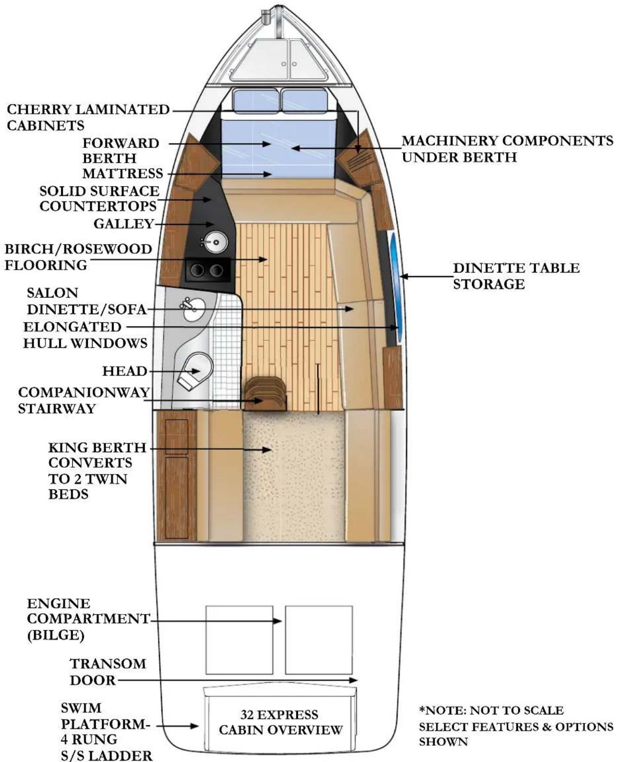
32 EXPRESS DECK FEATURES

*NOTE: NOT TO SCALE SELECT FEATURES & OPTIONS SHOWN
TECHNICAL DRAWINGS
Technical Information
![graph LR A["30 amp"] --> B["Shore Cable"] C["30 amp"] --> D["Main breaker #2"] B --> E["FS60"] D --> E E --> F["AC Ground Bus"] G["Line N Main breaker #1"] --> H["Line"] I["Line N Main breaker #2"] --> J["Line"] K["Line N Main breaker #1"] --> L["Line"] M["Line N Main breaker #2"] --> N["Line"]](/content/2026/05/1030542/images/03f84ecbe205df1235d811ce9e523edd6c337aca1b438a95e9f949bd80563592.jpg)
32 EXPRESS GALVANIC ISOLATOR WIRING
Technical Information
![graph TD A["Trunk Termination Resistor"] --> B["NMEA 2000 to/from USB Gateway"] B --> C["Laptop"] C --> D["Display"] D --> E["Compass"] E --> F["Battery"] F --> G["Engine Monitor"] G --> H["Trunk Termination Resistor"] H --> I["NMEA 0183 Instrument"] J["Drop Line"] --> K["Tee Connector"] L["Speed Tr…](/content/2026/05/1030542/images/cb8c21d911ba391ab9c6edf5d35ae864eb5bd3f3599db79d01e4b058f9e9eec6.jpg)
TYPICAL NMEA 2000 NETWORK COMPONENTS
Technical Information
![graph TD A["ELCI SINGLE POLE BREAKER"] -->|BLUE=NEUTRAL BROWN=120 VOLTS RED=120 VOLTS| B["SHORE POWER INLET"] B -->|GREEN=GRD.| C["GALVANIC ISOLATOR"] C -->|GREEN=GRD.| D["MAIN AC CONTROL PANEL LINE 1 & 2 BREAKERS"] D -->|AC BRANCH CIRCUITS.| E D -->|GREEN/YELLOW=| F F -->|GREEN=GRD.| C style A fill…](/content/2026/05/1030542/images/acda747159af8962e0e4c927b6fa6ba82772fe570974aa1edbad8d5d1b883d46.jpg)
32 EXPRESS ELCI AC CIRCUIT FLOW CHART (TYPICAL)
Technical Information

32 EXPRESS MAIN AC SHIP'S PANEL (FRONT VIEW)
Technical Information
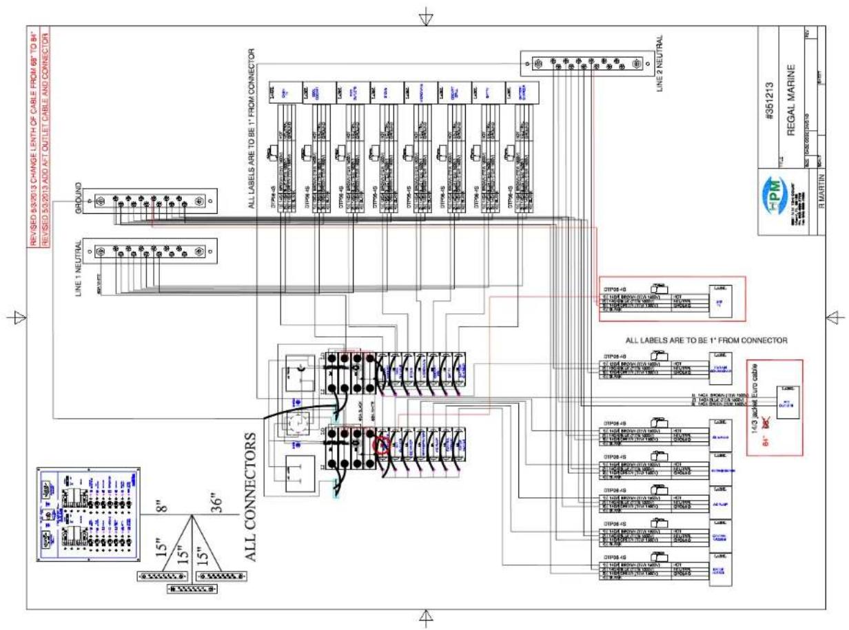
32 EXPRESS MAIN AC SHIP'S PANEL (REAR VIEW)
Technical Information
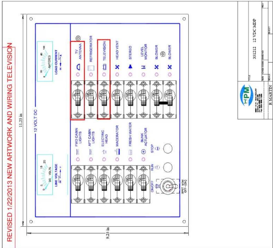
32 EXPRESS MAIN DC SHIP'S PANEL (FRONT VIEW)
Technical Information

32 EXPRESS MAIN 12 VOLT DC SHIP'S PANEL WITH BREAKER SIZES (REAR VIEW)
Technical Information

32 EXPRESS COCKPIT SWITCH PANEL
Technical Information
![graph TD A["House"] --> B["VSR"] B --> C["Engine"] C --> D["Engine"] D --> E["Main DC GROUND BUSS"] style A fill:#f9f,stroke:#333 style B fill:#ccf,stroke:#333 style C fill:#cfc,stroke:#333 style D fill:#fcc,stroke:#333 style E fill:#ffc,stroke:#333](/content/2026/05/1030542/images/c8df90706ade6f193ced66eb8031081d4950926dc3a999596523acfd06bb0a94.jpg)
32 EXPRESS BATTERY VSR CIRCUITRY
Technical Information
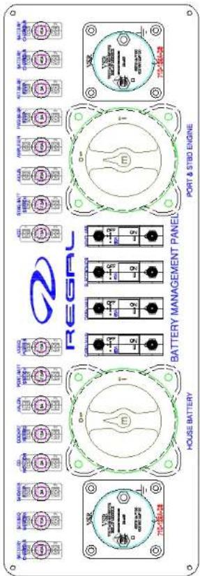

32 EXPRESS BATTERY MANAGEMENT PANEL
Technical Information


32 EXPRESS HELM SWITCH PANEL
Technical Information
REGAL 3200 BOW RIDER
HELM BREAKER PANEL
REGAL # 321357

32 EXPRESS HELM BREAKER PANEL
Technical Information

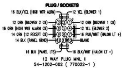
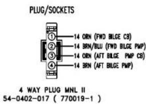
32 EXPRESS DECK HARNESS ROUTING-FORWARD
Technical Information

32 EXPRESS DECK HARNESS ROUTING-AFT
Technical Information

32 EXPRESS HULL HARNESS ROUTING
Technical Information

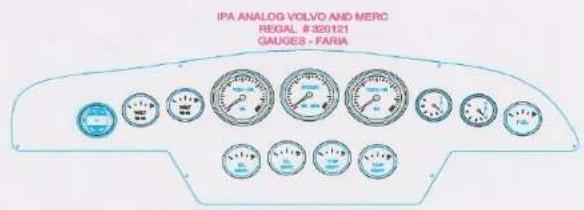

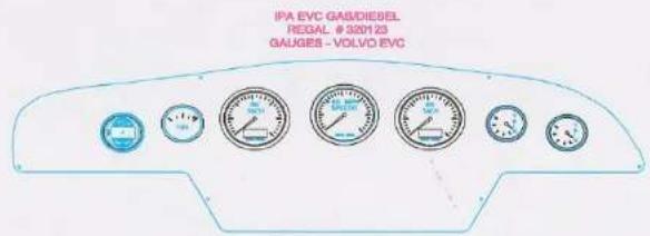

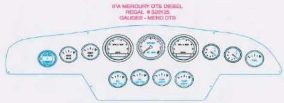
32 EXPRESS GAUGE PANEL CONFIGURATIONS
Technical Information
![graph TD A["MAIN-DISTRIBUTION PANELS"] --> B["STOCK"] B --> C["12 VDC"] B --> D["110 VAC"] B --> E["BATTERY CHARGER"] B --> F["STBD ENG"] B --> G["STBD ENG BATTERY"] B --> H["PORT ENG BATTERY"] B --> I["HOUSE BATTERY"] B --> J["FUEL LEVEL SENDER"] B --> K["GROUNDING TAB"] B --> L["NEUTRAL LINE 1"] B…](/content/2026/05/1030542/images/c31622d56f6024e4d9f1a3c8770550293bd8bf39bb06ccb31d238bcdee55689e.jpg)
32 EXPRESS TYPICAL DC GROUND CIRCUITRY
Technical Information
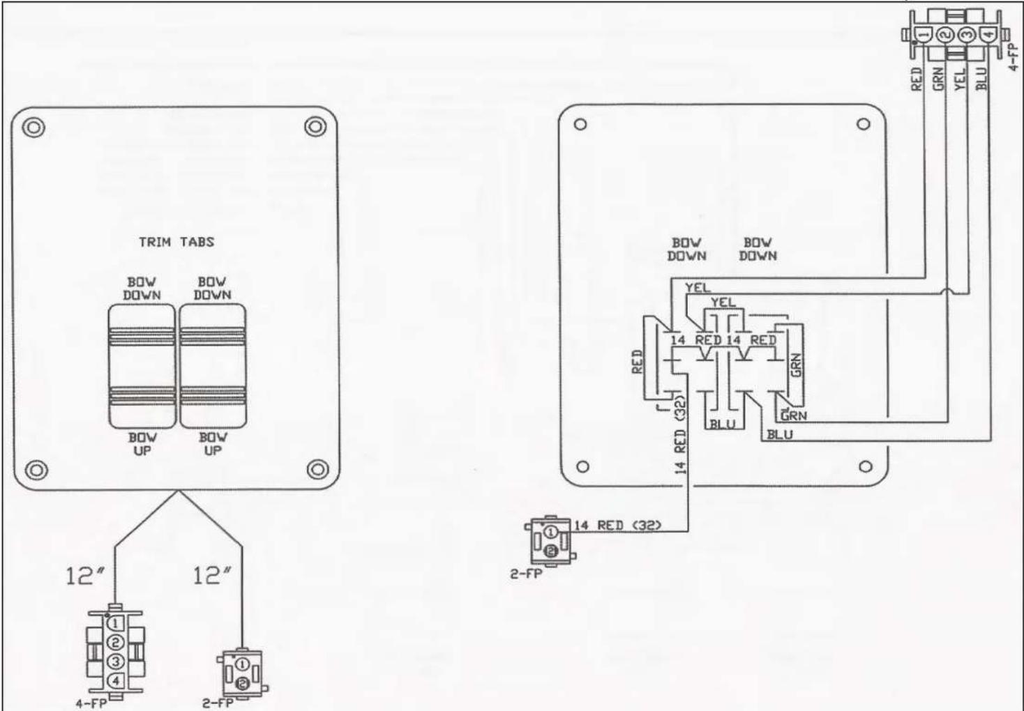
32 EXPRESS TYPICAL TRIM TAB SWITCH CIRCUITRY
Technical Information
![graph TD A["PORT (#31) BATTERY"] --> B["+"] C["HOUSE (#8d) BATTERY"] --> D["+"] E["STBD (#31) BATTERY"] --> F["+"] G["BATTERY SWITCHES"] --> H["HOUS"] I["D.C DISTRIBUTION CENTER (BREAKER BOX)"] --> J["+"] K["SOLENOID"] --> L["+"] M["HIGH WATER BILGE ALARM"] --> N["+"] O["WINDLASS"] --> P["+"] Q["STE…](/content/2026/05/1030542/images/06a8e4b0250e1c4354800c06bd3c5bb8ef4de162d00d2cb734c8f34d0eadeff9.jpg)
32 EXPRESS TYPICAL BATTERY MANAGEMENT PANEL CIRCUITRY
Technical Information
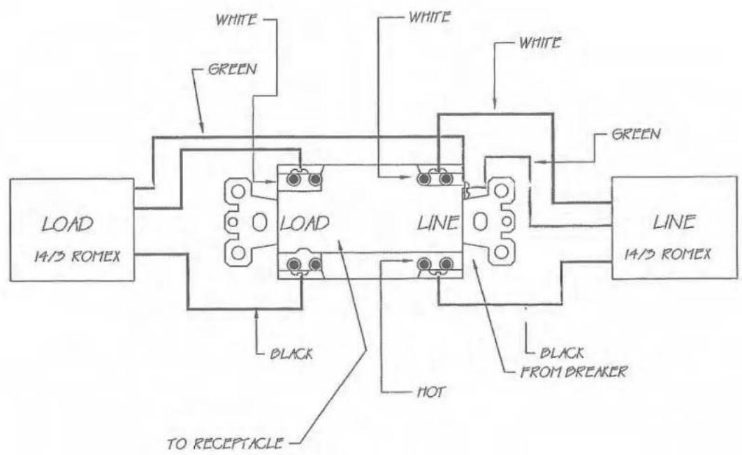
| REVISION DESCRIPTION | DR. BY: | APP. BY: | REV. DATE: | |
| REGAL BOATS | REGAL NAME INDUSTRIES3320 JEWEST DRIVECOLLABOR FUNDAY 22008-7005TELEPHONE (401) 881-4300 | |||
| DRAWING TITLE:1.10 VOLT GROUND FAULT CIRCUIT INTERUPTER | ||||
| DATE: | LATEST REV LET: | SCALE: | ||
| DR. BY: | APP. BY: | DWG. NO.: | ||
32 EXPRESS TYPICAL GFCI CIRCUITRY
Technical Information

NOTES:
1. FAILURE TO ISOLATE THIS GROUND WILL RESULT IN AN UNDESIRABLE OPERATION OF THE HALON EXTINGUISHER INDICATOR LIGHT.
2. FAILURE TO ISOLATE THIS GROUND WILL RESULT IN AN UNDESIRABLE OPERATION OF THE DIESEL SHUTDOWN SYSTEM.
| REVISION DESCRIPTION | DR. BY: | APP. BY: | REV. DATE: |
| REGN. MAPRE INDUSTRIES2001-800PRT DMCORANGE FLOOR 3000-THESTELEPHONE (407) 831-4300 | |||
| DRAWING TITLE:FIRE EXTINGUISHER SYSTEM GROUND | |||
| DATE: | LATEST REV NUMBER: | ### | |
| DR. BY: | DWG. NO.: | ||
32 EXPRESS TYPICAL FIRE EXTINGUISHER GROUND CIRCUITRY
Technical Information
MS-BT100 INSTALLATION DIAGRAM

NOTE: MS-BT100 is compatible with any stereo with an AUX IN. In instances where the AMPLIFIER ON cable is not provided, simply wire the POWER +12V cable of the MS-BT100 to the POWER +12V of the connecting stereo.
32 EXPRESS STEREO BLUETOOTH WIRING
Note: Before lifting vessel ensure that all straps are located at the sling marker positions as found on the deck. Measure for the above strap width positions before lifting the vessel. Tie a line between front and rear straps on both sides to prevent the vessel straps from moving during the lift operation.
Technical Information
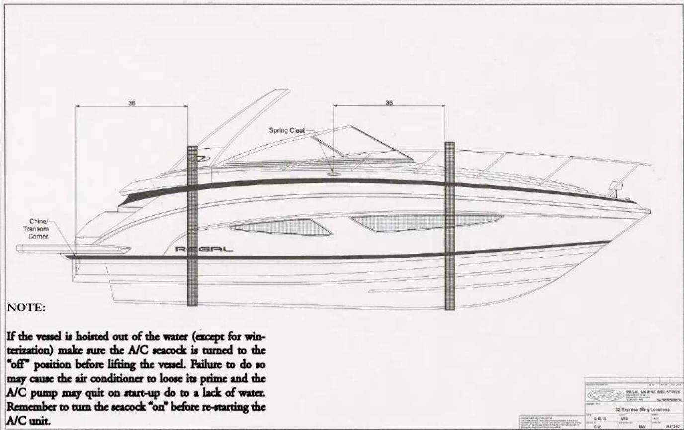
32 EXPRESS ESTIMATED DIMENSIONS W/ SLING LOCATIONS
Technical Information
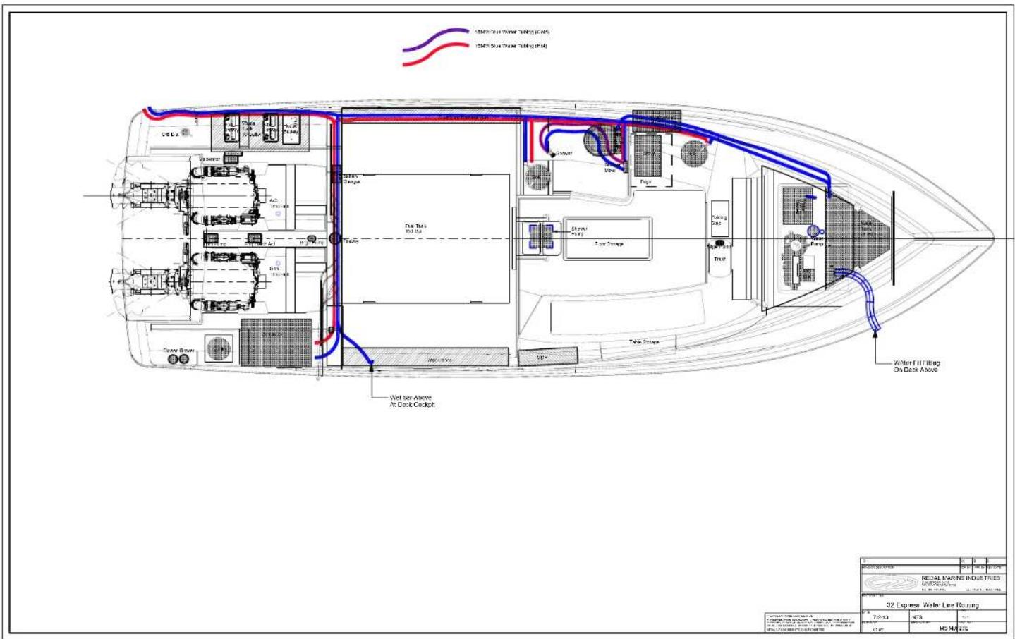
32 EXPRESS PLUMBING RUNS
TYPICAL VACUUM TYPE PLUMBING LAYOUT
WASTE SYSTEM-LATER MODELS
![graph TD A["Toilet Bowl"] --> B["1"] C["Solenoid Valve"] --> D["2"] E["Fresh Water Pressure Pump"] --> F["3"] G["System Vent"] --> H["4"] I["Holding Tank"] --> J["5"] K["Fresh Water Tank (System can also run from dockside water supply)"] --> L["6"] M["Forward Head"] --> N["3"] O["Aft Head"] --> P["3…](/content/2026/05/1030542/images/17f849baf568e42f39e4449c312cc61a8d743146677c2f8af2e8c9e2260c9877.jpg)
Technical Information
Technical Information

32 EXPRESS MACHINERY LAYOUT
Technical Information
PORT DETAIL


REGAL # 320114
FMT-150A-RMB
EPA COMPLIANT
182 LBS


NOTES:
PICK UP TUBES = 3/8' MPT W ALUM ASV 3/8' BARB
ASV IS 15' VERSION < LOW RESTRICTION
RETURN LINES DO NOT HAVE PICK UP TUBES
LIFT EYES - AT DESECRATION OF TANK MAKER
6 HOLD DOWN BRACKETS TOTAL
2012 EPA TANK DESIGN-CONFIRM 2 DEG +/- PORT/STBD
4 DEGREE +/- FORE/AFT NON TRAILERABLE BOAT
INCLUDE BACK FLOW PROTECTION - CERAMIC COAT TANK
| REVISION DESCRIPTION X | DR. BY: X | APP. BY: X |
| MUST COMPLY WITH APPLICABLE ARIC & NAMA SPECIFICATIONS | ||
| REGAL BOATS REINAL ITEMS INSTRUCTIONS 2001-DEC-2014 GENERAL FLOWER (2001-DEC-2015) TAPLINES (2014) 861-090 | ||
| DRAWING TITLE: FUEL TANK "JP" | ||
| DATE: 09/4/12 | LATEST REV LE: C. | SCALE: |
| DR. BY: R. OILS | APP. BY: | DWG. NO.: |
32 EXPRESS FUEL TANK EPA COMPLIANT
Technical Information
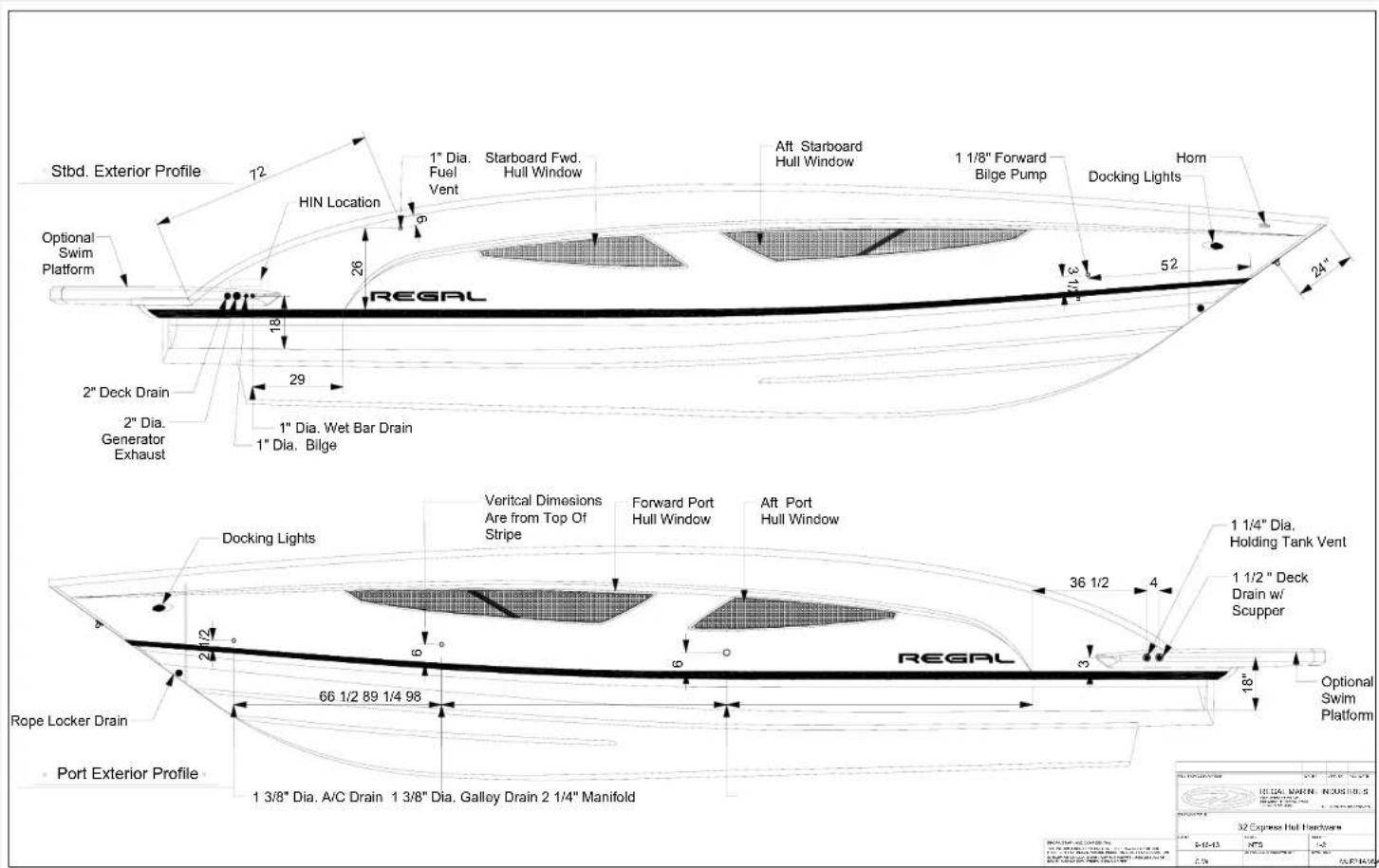
32 EXPRESS HULL HARDWARE
Technical Information
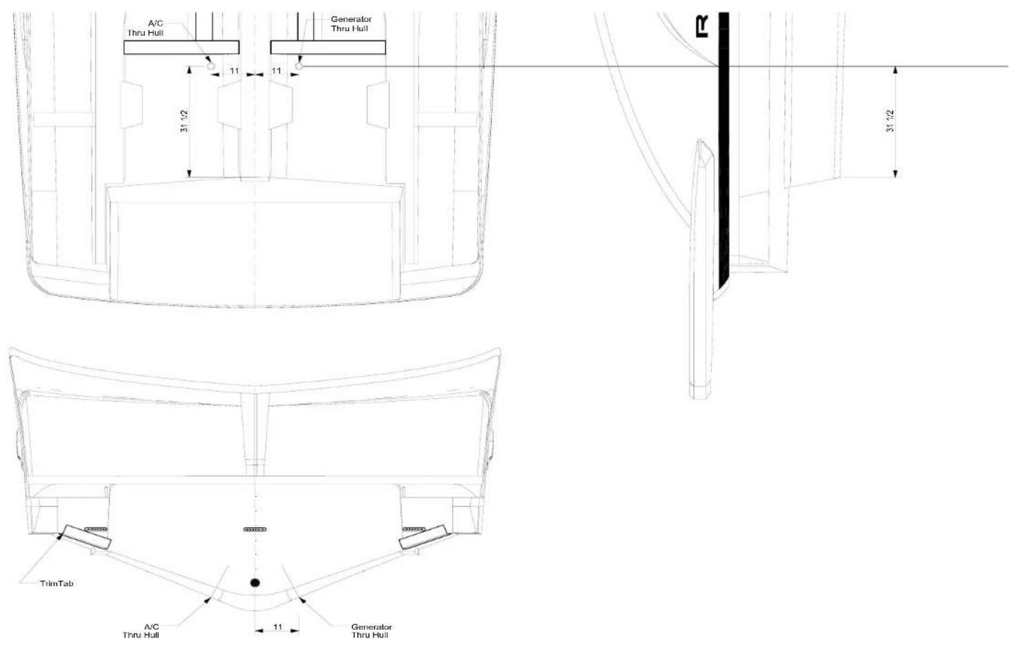
32 EXPRESS GENERATOR & AC THRU-HULLS
Technical Information

32 EXPRESS COCKPIT SEATING POSITION PLAN
Technical Information

32 EXPRESS RANGE OF VISIBILITY
Technical Information
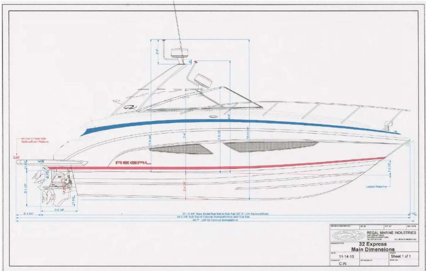
32 EXPRESS DIMENSIONS (APPROXIMATE)
Technical Information

Deck Bow Plan

32 EXPRESS BOW PLAN-WINDLASS
- 32 EXPRESS
- OWNER'S MANUAL
- NOTE
- REGAL®
- 1 INTRODUCTION
- 2 SAFETY ON BOARD
- 3 RULES OF THE ROAD
- 4 SYSTEMS
- 5 ENGINE/CONTROLS
- 6 VESSEL OPERATION
- EXTERIOR EQUIPMENT
- 8 COSMETIC CARE & MAINTENANCE
- 9 TROUBLESHOOTING
- 10 STORAGE & WINTERIZATION
- 11 GLOSSARY & INDEX 11-1
- 12 TECHNICAL
- INTRODUCTION
- WELCOME TO REGAL
- REGAL MARINE INDUSTRIES, INC. MISSION STATEMENT
- OWNER'S PACKETREGAL OWNER'S
- GENERAL INFORMATION
- HULL IDENTIFICATION NUMBER (HIN)
- VESSEL INFORMATION SHEET
- VESSEL FLOAT PLAN
- NMMA YACHT CERTIFICATION PLATE
- VESSEL INFORMATION
- VESSEL CRUISE CHECKLIST
- RECOMMENDED ON BOARD EQUIPMENT
- TOOLS
- SPARE PARTS
- BASIC GEAR & SUPPLIES
- OWNER'S REGISTRATION & SYSTEMS DEALER'S RESPONSIBILITY CHECKLIST
- OWNER'S RESPONSIBILITY
- CUSTOMER SERVICE
- REGAL MARINE INDUSTRIES, INC. LIMITED WARRANTY
- REGISTRATION INFORMATION
- GENERAL PROVISIONS
- SAFETY ON BOARD
- SAFETY LABELS
- SAFETY PRECAUTION DEFINITION
- WARNING
- CAUTION
- NOTICE
- DANGER
- INFORMATION
- PRECAUTIONARY LABELS
- GENERAL BOATING SAFETY
- REQUIRED SAFETY EQUIPMENT
- PERSONAL FLOTATION DEVICES
- PFD'S FOR PETS
- MAINTAINING YOUR PFD'S
- FIRE EXTINGUISHERS
- U.S.C.G APPROVED FIRE EXTINGUISHER TYPES & FEATURES
- VISUAL DISTRESS SIGNALS
- PYROTECHNIC DEVICES
- NON-PYROTECHNIC DEVICES
- INTERNATIONAL DISTRESS SIGNALS
- SOUND PRODUCING DEVICES
- RADIO COMMUNICATIONS
- NAVIGATION LIGHTS
- MARINE SANITATION DEVICES
- NAVIGATION RULES
- NAVIGATION LIGHT RULES
- BOATS LESS THAN 12 METERS IN LENGTH
- BOATS 12 METERS BUT LESS THAN 20 METERS IN LENGTH
- LOCATION OF LIGHTS
- EXCEPTIONS
- POLLUTION REGULATIONS
- DISCHARGE OF OIL PROHIBITED
- MARPOL TREATY
- GARBAGE DISCHARGE
- LIFE RAFTS
- USCG MINIMUM EQUIPMENT REQUIREMENTS
- EXHAUST & CARBON MONOXIDE
- HOW DOES CO AFFECT US
- A FEW NOTES ABOUT DIESEL/CO POISONING
- CARBON MONOXIDE DETECTORS
- AT LEAST ANNUALLY
- BOATING & ALCOHOL
- ALCOHOL MYTHS AND FACTS
- BOATING ACCIDENTS
- REPORTING BOATING ACCIDENTS
- RENDERING ASSISTANCE
- FEDERAL REGULATIONS RE- GARDING VESSEL SECURITY
- WATER SPORTS
- SWIM PLATFORM
- FISHING
- WEATHER/WATER CONDITIONS WAVES & FOG
- CLOUD FORMATIONS
- RULES OF THE ROAD
- NAVIGATION RULES DEFINED
- RIGHT OF WAY
- LOOKOUTS
- WHISTLE SIGNALS
- NAVIGATION AIDS
- REGULATORY MARKERS
- NIGHT RUNNING
- BRIDGE CLEARANCE
- BRIDGE LIGHTING
- SYSTEMS
- OVERVIEW
- TYPICAL GASOLINE FUEL SYSTEM
- GASOLINE SPECIFICATIONS
- FUEL TANK
- FUEL FILL FITTING
- FUEL VENT FITTING
- ANTI-SIPHON VALVE
- FUEL GAUGE/SENDER
- FUEL FILTERS
- CARBON CANISTER
- GASOLINE VENTILATION SYSTEM
- GASOLINE FUEL SYSTEM-GENERAL
- POSSIBLE GASOLINE FUEL PROBLEMS/SOLUTIONS
- DIESEL FUEL SYSTEM- GENERAL
- DIESEL FUEL BASICS
- SOLUTIONS FOR RECOVERING DIESEL FUEL QUALITY
- DIESEL VENTILATION SYSTEM
- TYPICAL DIESEL FUEL SENDER
- TYPICAL DIESEL FUEL TANK FILL/VENT
- TYPICAL DIESEL FUEL SYSTEM FILTERS
- TO DRAIN RACOR WATER SEPARATOR FILTER
- TO PRIME RACOR WATER SEPARATOR FILTER
- TO REPLACE WATER SEPARATOR FILTER ELEMENT
- NOTES-ELEMENT REPLACEMENT
- TYPICAL SECONDARY ENGINE MOUNTED DIESEL FUEL FILTER
- TO DRAIN, PRIME OR REPLACE SECONDARY FUEL FILTER ELEMENT
- POSSIBLE FUEL PROBLEMS/SOLUTIONS
- FUEL FILTER ELEMENTS CONTAIN "ALGAE" OR EXHIBIT A BROWN OR BLACK COLOR AND/OR SHOW WATER IN THE FUEL SYSTEM
- ELECTRICAL INTRODUCTION
- DIRECT CURRENT (12 VOLTS)
- BATTERY (12 VOLTS) DESCRIPTION
- BATTERY TERMINOLOGY
- POSSIBLE PROBLEMS/SOLUTIONS
- TYPICAL BATTERY MANAGEMENT SYSTEM COMPONENTS
- TYPICAL REMOTE BATTERY SWITCH REMOTE BATTERY SWITCH OPERATION
- TYPICAL BREAKER
- TYPICAL BATTERY CHARGER
- TYPICAL CHARGING SYSTEM- SUMMARY NOTES
- BATTERY E-Z CHARGE SYSTEM
- TYPICAL BATTERY MANAGEMENT SYSTEM-GENERAL INFORMATION
- MANAGEMENT PANEL MAIN CIRCUIT DC BREAKER CLUSTER
- DVSR (DIGITAL VOLTAGE SENSITIVE RELAY)
- POSSIBLE PROBLEMS/SOLUTIONS (DVSR)
- TYPICAL BATTERY MANAGEMENT SYSTEM-BREAKER SIZE/DESCRIPTION
- PORT MANAGEMENT PANEL BREAKER CLUSTER
- STARBOARD MANAGEMENT PANEL BREAKER CLUSTER
- MAIN CIRCUIT BREAKER CLUSTER
- TYPICAL 12 VOLT MAIN DC PANEL METER/BREAKER SWITCH FUNCTIONS
- TYPICAL 12 VOLT HELM BREAKER PANEL
- TYPICAL 12 VOLT HELM BREAKER PANEL DESCRIPTION
- TYPICAL 12 VOLT HELM SWITCH PANEL
- TYPICAL 12 VOLT HELM SWITCH PANEL DESCRIPTION
- (AC) ALTERNATING CURRENT-GENERAL INFORMATION
- BASIC ELECTRICAL TERMS
- ALTERNATING CURRENT LOAD MANAGEMENT
- DOCKSIDE (SHORE POWER) CORD SYSTEM
- TIPS-MARINA SHORE POWER STATIONS
- ELCI SYSTEM
- TYPICAL ELCI SYSTEM OVERVIEW
- ELCI LEAKAGE FAULT DETECTOR LED INFORMATION
- GREEN LED ON- RED LED OFF
- GREEN LED OFF, RED LED ON
- GREEN LED FLASHING, RED LED OFF
- GREEN LED OFF, RED LED OFF
- GREEN LED FLASHING, RED LED OFF, AMBER LED ON
- TYPICAL ELCI AC CIRCUIT FLOW CHART
- TYPICAL GALVANIC ISOLATOR
- PRECAUTIONS/GALVANIC ISOLATOR WARNINGS
- SHOREPOWER PANEL DISTRIBUTION
- TYPICAL AC MAIN AC CONTROL PANEL
- REVERSE POLARITY INDICATOR
- PANEL MAIN BREAKERS
- 50 AMP AC GENERATOR BREAKER
- LINE VOLTAGE/CURRENT METERS
- 120 VOLT MAIN PANEL BREAKER DESCRIPTION (TYPICAL)
- LEG A
- LEG B
- GFCI OUTLET
- GFCI'S (GROUND FAULT CIRCUIT INTERRUPTER
- TESTING GFCI'S
- IGNITION PROTECTED DEVICES
- POSSIBLE PROBLEMS/SOLUTIONS (GFCI'S)
- TYPICAL AC GENERATOR (GEN-SET)
- TYPICAL GENERATOR FUEL SYSTEM
- GENERATOR IN-LINE FUEL FILTER
- TYPICAL ELECTRICAL SYSTEM
- TYPICAL EXHAUST SYSTEM
- BEFORE STARTING GENERATOR
- STARTING GENERATOR-TYPICAL
- STOPPING GENERATOR
- TYPICAL AIR CONDITIONING SYSTEM
- REVERSE HEAT
- TYPICAL AIR CONDITIONING SYSTEM OPERATION
- TYPICAL ELITE AC CONTROL DIAGRAM
- TYPICAL A/C INSPECTION TIPS
- POSSIBLE PROBLEMS/SOLUTIONS (A/C)
- TYPICAL FRESH (POTABLE) WATER SYSTEM
- FILLING WATER TANK AT THE DECK FILL
- USING FRESH WATER (POTABLE) SYSTEM
- FRESH WATER PRESSURE PUMP
- OPERATING TYPICAL STANDARD DOCKSIDE WATER SYSTEM
- TYPICAL MONITOR PANEL
- SANITIZING WATER SYSTEM
- TRANSOM SHOWER
- TYPICAL HOT WATER HEATER
- TYPICAL SHOWER SUMP PUMP SYSTEM
- POSSIBLE PROBLEMS/SOLUTIONS-FRESH WATER SYSTEM
- TYPICAL WASTE WATER SYSTEM
- GRAY WATER SYSTEM
- TYPICAL WASTE WATER SYSTEM DESCRIPTION (BILGE LOCATION)
- HEAD (TOILET) SYSTEM
- USING VACUUM STYLE TOILET
- TYPICAL MACERATOR (OVERBOARD DISCHARGE PUMP)
- POSSIBLE PROBLEMS/SOLUTIONS-WASTE SYSTEM-LATER MODELS
- TYPICAL WASTE SYSTEM-VACUUM STYLE MODELS
- TRIM TABS
- RECTIFYING A LIST
- TRIM TAB PUMP
- PORPOISING
- TYPICAL WINDLASS
- WINDLASS SAFETY TIPS & WARNINGS
- WINDLASS ANCHOR LINE
- TYPICAL WINDLASS HARDWARE
- WINDLASS COMPONENTS
- RETRIEVING ANCHOR
- INDEPENDENT WARPING
- MANUAL FREE FALL
- TYPICAL ENTERTAINMENT SYSTEM
- ANTENNA SWITCH
- PREPARING TO USE ENTERTAINMENT SYSTEM COMPONENTS
- DVD PLAYER
- TYPICAL SALON DVD PLAYER
- DVD-CD
- CHECKING FOR DISC COMPATIBILITY
- DISC CARE
- WIPE STRAIGHT OUT
- DO NOT USE A CIRCULAR MOTION
- TYPICAL STEREO
- 700 SERIES
- IPOD AND IPHONE COMPATIBILITY
- MS-IP700
- MS-AV700
- BEFORE INSERTING IPOD OR IPHONE
- SELECTING THE CORRECT IPOD SLEEVE
- USER INTERFACE AND CONTROLS
- PRIMARY SOURCE
- ROTARY ENCODER AND MENU KEY
- ROTARY ENCODER OPERATION
- MENU KEY OPERATION
- ADJUSTING LEVELS
- ACCESSING MENUS
- OPENING CONTROL SCREENS
- GETTING STARTED
- POWERING THE UNIT ON OR OFF
- TO POWER THE UNIT ON OR OFF
- INPUT SOURCE SCREENS
- ADJUSTING VOLUME LEVEL
- TO ADJUST THE VOLUME LEVEL
- TURN THE ENCODER
- MUTING OUTPUT
- TO MUTE AND UNMUTE THE VOLUME
- IPOD
- PLAYING CONTENT
- TO LISTEN TO INPUT FROM YOUR IPOD
- IPOD SOURCE SCREEN
- SELECTING TRACKS FROM A PLAYLIST
- CONTROLLING PLAYBACK
- SUBTITLES
- ALBUM ARTWORK
- BEFORE CONNECTING IPOD
- TO INSERT YOUR IPOD
- MS-AV700I AND MS-IP700I MODELS
- TO CONNECT YOUR IPOD, YOU WILL NEED
- TO CONNECT YOUR USB FLASH DRIVE, YOU WILL NEED
- ELECTRONICS-TYPICAL
- SYSTEM OPERATION OVERVIEW
- CHARTPLOTTER
- TYPICAL RADAR
- RADAR OPERATION
- TYPICAL ENGINE MANAGEMENT SYSTEM
- TYPICAL VHF MARINE RADIO
- ENGINES & CONTROLS
- OVERVIEW- FUNDAMENTALS
- ENGINE BREAK-IN: ALL MODELS
- OIL CHANGES (ENGINE & DRIVE)
- VENTILATION SYSTEMS
- IGNITION SWITCH PANEL
- VOLVO AUX. STOP SWITCH
- INSTRUMENTATION (TYPICAL)
- FUEL GAUGE
- EVC HELM DISPLAY PANEL
- DEPTH GAUGE
- OIL PRESSURE READOUT-DISPLAY PANEL
- TEMPERATURE READOUT-DISPLAY PANEL
- SPEED READOUT-DISPLAY PANEL
- VOLTAGE READOUT-DISPLAY PANEL
- AUTOMATIC FIRE EXT. SYSTEM
- HIGH WATER ALARM
- BEFORE STARTING ENGINES
- AFTER STARTING ENGINES
- ELECTRONIC CONTROLS/STEERING
- MERCRUISER- GENERAL BUTTON FUNCTIONS
- JOYSTICK CONTROL-VOLVO
- VESSEL OPERATION
- GETTING UNDERWAY
- UNDERWAY QUESTIONNAIRE
- DISEMBARKING QUESTIONNAIRE
- BEFORE FUELING
- DURING FUELING
- AFTER FUELING
- STARTING & STOPPING
- STARTING GUIDELINES
- SHIFTING GUIDELINES
- STOPPING GUIDELINES
- FENDERS
- FENDER USAGE
- FENDER TYPES
- DOCK LINE BASICS
- BOW AND STERN LINES
- BREAST LINES
- SPRING LINES
- BOAT MOORING
- DOCK LINE SIZING
- DISEMBARKING-LEAVING THE DOCK
- SECURING LINES
- KNOTS
- DOCKING-GENERAL
- ANCHORING
- TOWING
- ADMIRALTY LAW
- EMERGENCIES
- FIRE
- SECONDS)
- FIRST AID
- CPR (BASIC LIFE SUPPORT)
- HYPOTHERMIA
- TREAT HYPOTHERMIA BY THE FOLLOWING
- CALIFORNIA AIR RESOURCE BOARD (CARB) LABEL
- CALIFORNIA PROP 65
- EXAMPLES INCLUDE
- TO AVOID HARM
- FUEL SPILLAGE
- ENVIRONMENTAL AWARENESS
- AUXILIARY EQUIPMENT OPERATION
- AUXILIARY COMPONENTS
- INTERIOR EQUIPMENT
- CO DETECTOR
- DOOR-COMPANIONWAY-TYPICAL
- FWD. BERTH-SLEEPER CONVERSION
- HATCH-TYPICAL
- LIGHTING-GENERAL
- HANGING LOCKER LIGHTS-TYPICAL
- READING LIGHTS-TYPICAL
- FLORESCENT LIGHTS
- MONITOR-WATER/WASTE
- PORT/STBD WINDOWS
- RANGE/STOVE-TYPICAL
- RANGE TOP CUT-OUT SWITCH
- REFRIGERATOR-TYPICAL
- TEMPERATURE SETTING-TYPICAL
- DEFROSTING
- NORMAL REFRIGERATOR OPERATING SOUNDS
- PERIODS OF NON-USE
- SALON TABLE-TYPICAL
- SALON-DINETTE TABLE SET-UP
- SEAT-HELM (TYPICAL)
- SOFA-CONVERSION TO SLEEPER
- TV (LED) MONITOR PRECAUTIONS
- VACUUM CLEANER SYSTEM-TYPICAL
- SAFETY WARNINGS
- OPERATION
- ANTENNAE
- DOOR-TRANSOM-TYPICAL
- ELECTRONICS-GENERAL
- FIRE EXTINGUISHER- AUTOMATIC
- OPERATION-AUTOMATIC
- OPERATION-MANUAL
- GENERATOR-TYPICAL
- HATCH-ENGINE
- HEATER-HOT WATER
- HIGH WATER ALARM-BILGE
- POSSIBLE CAUSES ARE
- MARKERS-FOR SLINGS-TYPICAL
- BOAT OWNER-LIFT OPERATOR
- OVERBOARD DISCHARGE PUMP (MACERATOR) TYPICAL
- IN-LINE WASTE VENT FILTER
- TYPICAL OVERBOARD DISCHARGE PUMP
- POWER TOWER-TYPICAL
- PRESSURE PUMP-FRESH WATER
- SATELLITE RADIO
- SHOWER-TRANSOM TYPICAL
- SPOTLIGHT-TYPICAL
- SUN LOUNGE-FWD. DECK
- SWIM (BOARDING) LADDER-TYPICAL
- THRUSTER-BOW (TYPICAL)
- GENERAL SAFETY NOTICES
- USING THRUSTER
- ULTRA SUN LOUNGE-AFT
- WARNING DO NOT OPERATE BOAT WITH ENGINE HATCH IN AFT POSITION
- UNDERWATER LIGHTING
- COSMETIC CARE & MAINTENANCE
- COSMETIC CARE
- BILGE/ENGINE COMPARTMENT
- CABINETS
- CANVAS CLEANING INSTRUCTIONS
- CLEAR VINYL, ZIPPER & SNAP CARE
- CARPET-INTERIOR
- GENERAL CARE AND MAINTENANCE
- REGULAR VACUUMING
- PROFESSIONAL CLEANING
- SPILLS
- CABIN DOOR/COCKPIT ENTRANCE MATS
- CARPET-COCKPIT TYPICAL
- STAIN REMOVAL
- COUNTERTOPS
- ELECTRIC BBQ
- STAINLESS STEEL SURFACES
- PORCELAIN ENAMEL
- FABRICS-INTERIOR
- FIBERGLASS & GELCOAT
- MINOR REPAIRS
- FLOORING-HARDWOOD
- GAUGES/SWITCH PANELS
- HULL/DECK
- HULL BOTTOM
- MICROWAVE OVEN
- PLASTICS
- RANGE/STOVE
- SPOTLIGHT
- STAINLESS STEEL
- STAINS
- FREQUENT STAINS CLEAN-UP STEPS
- 1 2 3
- UPHOLSTERY
- BALLPOINT PEN REMOVAL INSTRUCTIONS
- MAINTENANCE
- AIR CONDITIONER
- REVERSING VALVES
- SEAWATER STRAINER
- TYPICAL VECTOR COMPACT AC SYSTEM
- CONDENSER COIL CLEANING
- AIR FILTERS
- BATTERIES
- BATTERY MAINTENANCE
- BATTERY SWITCH MANAGEMENT PANEL
- TYPICAL BILGE PUMP/FLOAT SWITCH
- CARBON MONOXIDE DETECTOR
- CO SENTINEL CARBON MONOXIDE ALARM
- TO REMOVE CIRCUIT BOARD FROM BASE PLATE
- FOLLOW THESE TWO STEPS
- TO INSTALL CIRCUIT BOARD INTO BASE PLATE, FOLLOW THESE TWO STEPS
- DOOR-CABIN ENTRY
- ELECTRONICS-GARMIN
- ELECTRONICS-VHF RADIO
- FIRE EXTINGUISHING SYSTEM-AUTOMATIC
- FUEL SYSTEM
- GENERATOR OPTION-TYPICAL
- GROUND FAULT OUTLET
- HORN (TYPICAL AIR OPERATED)
- PLUMBING CONNECTORS
- PUMP-OVERBOARD DISCHARGE
- SHOWER SUMP PUMP-TYPICAL
- STEREO/DVD PLAYER/TELEVISION
- TELEVISION FLAT SCREEN MONITOR
- UNDERWATER HARDWARE-SEACOCKS & STRAINERS
- TOILET-VACUUM DESIGN
- THRUSTER-BOW
- CLEANING STRETCH HOSE
- WINDLASS
- TROUBLESHOOTING
- DIAGNOSTIC CHARTS
- STEREO DIAGNOSTIC CHART
- TACHOMETER-ELECTRONIC DIESEL
- SYMPTOM
- CALIBRATION
- VACUUM CLEANING SYSTEM
- IF THE MOTOR STOPS SUDDENLY
- STORAGE & WINTERIZATION
- DECOMMISSIONING CHECKLIST
- BOAT
- ENGINES
- GENERAL NOTES ON ANTIFREEZE
- AIR CONDITIONING
- WASTE/TOILET SYSTEM
- WATER SYSTEM-FRESH
- DISENFECTION OF POTABLE WATER SYSTEM
- GLOSSARY & INDEX
- GLOSSARY
- A
- B
- C
- D
- E
- F
- G
- H
- I
- J
- K
- L
- M
- N
- O
- P
- R
- S
- U
- V
- W
- Z
- T
- TECHNICAL
- TECHNICAL INFORMATION
- TECHNICAL DRAWINGS
- 32 EXPRESS GAUGE PANEL CONFIGURATIONS
- 32 EXPRESS TYPICAL FIRE EXTINGUISHER GROUND CIRCUITRY
- 32 EXPRESS STEREO BLUETOOTH WIRING
- TYPICAL VACUUM TYPE PLUMBING LAYOUT
- 32 EXPRESS FUEL TANK EPA COMPLIANT
Brand : Regal
Model : 32 Express
Category : Boat