
Wireless HD Sender - Audio/Video Transmitter MEGASAT - Free user manual and instructions
Find the device manual for free Wireless HD Sender MEGASAT in PDF.


| Product Type | Wireless HD Video/Audio Transmitter |
| Transmission Technology | 5.8 GHz (may vary by region) |
| Max Transmission Range | Up to 30 meters (98 feet) indoors (walls reduce range) |
| Number of Channels | 4 selectable channels to avoid interference |
| Video Input/Output | HDMI (cables included) |
| Max Video Resolution | 1080p Full HD |
| Audio Support | Stereo audio via HDMI |
| Power Supply | 5V DC, 1A (adapter included) |
| Power Consumption | Transmitter: < 2W; Receiver: < 2W |
| Dimensions (Transmitter) | Approx. 80 x 50 x 20 mm |
| Dimensions (Receiver) | Approx. 80 x 50 x 20 mm |
| Weight (per unit) | Approx. 50 g (without cables) |
| Operating Temperature | 0°C to 40°C |
| Storage Temperature | -10°C to 50°C |
| Key Features | Plug-and-play, no software required; supports IR remote extension |
| Cleaning Instructions | Wipe with a dry, soft cloth; do not use liquid or aerosol cleaners |
| Safety Precaution | Do not expose to moisture; keep away from heat sources |
| Spare Parts / Repair | Contact manufacturer for replacement adapters or cables |
| General Info | Brand: Megasat; Model: Wireless HD Sender |
Frequently Asked Questions - Wireless HD Sender MEGASAT
User questions about Wireless HD Sender MEGASAT
0 question about this device. Answer the ones you know or ask your own.
Ask a new question about this device
Download the instructions for your Audio/Video Transmitter in PDF format for free! Find your manual Wireless HD Sender - MEGASAT and take your electronic device back in hand. On this page are published all the documents necessary for the use of your device. Wireless HD Sender by MEGASAT.
USER MANUAL Wireless HD Sender MEGASAT
natural_image
Abstract blue curved lines on white background (no text or symbols)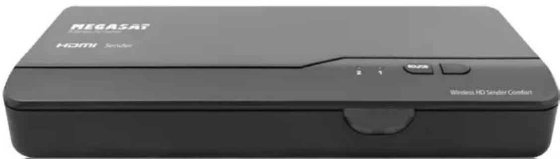
natural_image
Exterior view of a black MEGASAT HDMI Sender device with control buttons and ventilation slots (no readable text beyond branding)natural_image
Black rectangular device with three blue dots and three connected points, no visible text or symbolsnatural_image
Back view of a black electronic device with control buttons and indicator lights (no text or symbols visible)Installation Installation
Installation Installation
natural_image
Diagram showing two batteries with different internal structures, one open and one closed, both with arrows indicating direction (no text or symbols present)natural_image
Two black electronic devices with labeled ports and connectors, one showing internal components and the other a connected port (no visible text or symbols)natural_image
Two black electronic devices with circular buttons and a finger pointing at them, connected by wireless signals (no text or symbols visible)Installation Installation
natural_image
Diagram showing three devices with sound waves, one emitting a stopwatch (no text or symbols present)Installation Installation
natural_image
Line drawing of a device rear panel with ports and buttons (no text or symbols)natural_image
Line drawing of a rectangular electronic device with labeled ports and buttons (no text or symbols)natural_image
Exterior view of a black NEGAAT home audio amplifier device (no visible text or symbols on body)
natural_image
Exterior view of a black NEGRSAT HATHI Wireless HD Limley Comfort device (no visible text or symbols on body)


Table of Contents Safety Instructions
-
Safety Instructions....03
-
Introduction 04
-
Packing content 04
-
Overview
Transmitter 05
Receiver 06
Remote control....07
- Installation
Step 1: Setup the Transmitter ....08
Step 2: Setup the Receiver....09
Step 3: Setup the Blaster and IR Sensor....10
Step 4: Boot up the Transmitter and Receiver.....11
Step 5: Mounting the devices to the wall.....15
-
Troubleshooting 16
-
Supported Resolution 17
-
Audio Bitrate Resolution 18
-
Specifications 18
This device has been designed and manufactured to satisfy the international safety standards. Please read the following safety precautions carefully before operating this device.
Main Supply:
Before operating, please check the units operating voltage is 100\~240V AC 50/60Hz.
Overload:
Do not overload a wall outlet, extension cord or adapter, neither use damaged power cord or touch it with wet hand as this may result in electric shock.
Liquid:
The receiver shall not be exposed to dripping or splashing water, and that no objects filled with liquids, such as base, shall be placed on the apparatus.
Ventilation:
Keep the slots on top of the receiver uncover to allow sufficient airflow to the unit. Do not put the device on soft furnishings or carpets. Do not expose the receiver to direct light or do not place it near a heater or in humid conditions. Do not stack other electronic equipments on top of the device.
Risk of suffocation:
Do not let children play with films or other packaging components, there is a risk of suffocation.
Cleaning:
Plug out the receiver from the wall outlet before cleaning. Clean the receiver by a soft cloth or mild solution of washing-up liquid (no solvents).
Location:
Put the device indoor in order to avoid lightening, raining or sunlight.
Uncover:
Do not remove the cover, to reduce the risk of electric shock. Contact qualified and licensed service personnel to repair the device, or contact your dealer.
Introduction Overview
The Wireless HD Sender Comfort is a Full HD wireless transmission device.
This solution delivers uncompressed 1080p Full HD video and audio content to your existing HDTV set wirelessly. It operates the transmission in 4.9 GHz \~ 5.9 GHz frequencies and it can adjust its communication frequency automatically in case of interference from another RF system. With built-in Omni-directional antennas, it can transmit uncompressed video content to 20 meters (66 feet) LOS (Line of sight) with no latency.
Both IR Sensor Extender Cable and IR Blaster Extender Cable are included in the package so users can point their remote control of the AV source at the receiver directly for device operation.
Packing content
- Transmitter
- Receiver
• Power supply (Transmitter)
• Power supply (Receiver) - IR Sensor
- Remote control
• HDMI Cable - Quick installation guide
- 2x Anchors
• 2x Screws
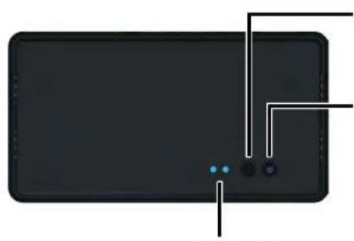
Transmitter top view
natural_image
Front view of a black rectangular device with three blue dots and connecting lines, no visible text or symbolsSource Selection Button
Press to switch Source inputs of the transmitter.
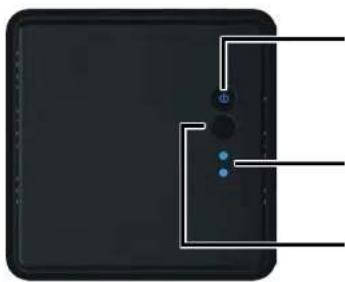
Press to turn the transmitter on and off. The indicator in the power button is lit in solid blue when the power is on, and turns red in standby mode.
These two LED indicators are lit insolid blue to show current input you switch.
Power Button with LED Indicator
Source LEDs
Transmitter rear view
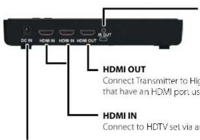
IR OUT Blaster Extender Jack
Press to switch Source inputs of the transmitter.
Connect Transmitter to High-definition audio/video devices that have an HDMI port using a provided HDMI cable.
Connect to HDTV set via an HDMI cable.
For connecting the SWW1810T power adapter.
DC IN
Overview Overview
Receiver top view
natural_image
Top-down view of a black electronic device with three blue indicator lights and a control panel (no text or symbols visible)Power Button with LED indicator
Press to turn the receiver on and off. The indicator in the power button lights up in blue when the power is on, and turns red in standby mode.
Source LEDs
For HDMI1 and HDMI2 selected indication.
Source Button
Press this button for Source input selection.
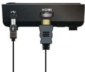
Receiver rear view
natural_image
Close-up of a black HDMI cable connector with two connected cables (no visible text or symbols)HDMI OUT
Connect to HDTV set via an HDMI cable
DC IN
Connect to receiver's power adapter.
Remote control
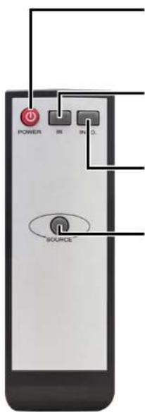
POWER Button
Press to turn the Transmitter & Receiver on/off. When both of TX & RX Power LEDs are red, press Power button either TX OR RX, it can wake up each other automatically.
IR Button
Press to switch the IR Blaster frequency to meet Source device's requirement. It can switch IR Blaster frequency 47K to 56K to 36K recurring.
INFO Button
Press this button to display OSD for system related information on HDTV connected on receiver.
SOURCE Button
Press to switch the audio/video sources input connected to transmitter directly.
Installation Installation
Step 1: Setup the Transmitter
Connect two High-Definition Audio/Video Sources to the transmitter HDTV set Connection with RECEIVER
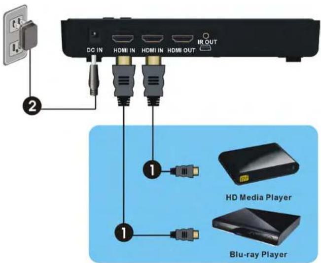
- Connect the transmitter's "HDMI IN" to the High-Definition AV sources' "HDMI OUT" through by HDMI cable. The transmitter has two HDMI inputs for the High-Definition source device, like PS3, Blu-ray Player.
- Connect the supplied power adapter to the DC IN jack of the transmitter and a wall socket. The LED indicator in the POWER button lights up in blue when the TRANSMITTER is connected to the power mains.
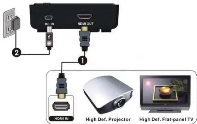
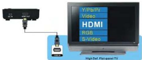
- Connect the HDMI cable to the HDMI OUT jack of the receiver and to your HDTV set (or an HD projector). Press the Source / Input button of your TV's remote to select the appropriate "HDMI" video input.
- Connect the supplied power adapter to the DC IN jack of the receiver and a wall socket. The POWER LED indicator lights up in blue when the receiver is connected to the power mains.
Installation Installation
Step 3: Setup the Blaster and IR Sensor S
If necessary, connect the Infrared (IR) blaster (or sensor) Extender cable. Users can point hand-held remote control of your High Definition AV equipment at the receiver or the HDTV set to operate the source devices, not exceeding the distance of 66 feet at Line-of-sight.
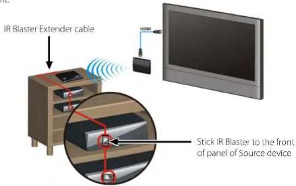
- Plug the IR blaster cable into the IR OUT jack of the transmitter.
- Please try to manually move the IR blaster in the front of the front panel of your HD device and then press the key of remote control to search a good position of IR response. Paste the IR blaster head near the front of IR sensor of your High-Definition audio/video devices.
- When the IR blaster cable is connected, it relays infrared command from your remote control to the device. Users can control their AV devices by pointing their remote control to the receiver instead of to their AV equipment.
NOTE:
- The IR sensor supports 36KI lz \~ 56KI lz (NLC, RC5, RC6) remote's signal protocol. Therefore, it is possible that some devices may not be supported.
-
The IR blaster supports 47KHz remote signal protocol.
-
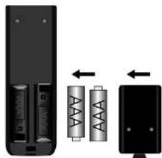
Place the two AAA batteries into the remote control.
natural_image
Diagram showing battery charging process with two batteries and one battery, no text or symbols present- After the power cord is plugged into the electrical outlet, the device will be turned on automatically.

natural_image
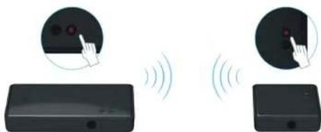
Two black electronic devices with labeled ports and connectors, shown from different angles (no text or symbols visible)- If it is in Standby mode (Both POWER LED of transmitter and receiver are lit in red), press the POWER button on both transmitter and receiver to turn on the transmitter and the receiver.
natural_image
Illustration of two electronic devices with circular indicators and a hand pointing to their screen (no text or symbols present)- If transmitter's HDMI out display is on (Transmitter POWER LED is lit in blue) and receiver stay in Standby mode (Receiver POWER LED is lit in red), press the POWER button of receiver ONLY to wake up and make connection between transmitter and the receiver for enable display out on receiver side.
NOTE:
User can press POWER button of transmitter to turn off both transmitter & receiver simultaneously any time.
Installation Installation
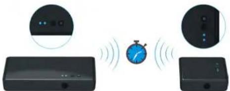
- During the warm-up, the POWER LED will blink in blue until the signal link between the TRANSMITTER and the RECEIVER is established. It will take 15 \~ 20 seconds for system boot up successfully.
natural_image
Diagram showing three devices connected via a stopwatch with signal waves, no text or symbols present- Ensure your TV set or projector is in "HDMI input" mode, and is already powered on.
- Press the Source button on the RCU or on the top of receiver / transmitter for Source input switch until you see the video being broadcasted from your device.
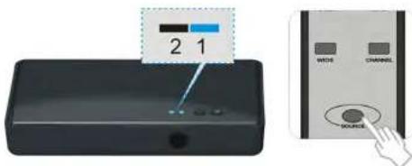
- If all operation is normal, the POWER LED and INFO./CHANNEL LED will glow in solid blue. Please refer to the below form containing detailed LED indicator and OSD description of transmitter / receiver:
| Item / Mode | Status Description | Power LED | Status LED OSD | Display |
| Standby | For power saving mode. | Static Red Off | ||
| Initial Boot up / Warm up | It will spend 15 ~ 20 seconds for system boot up. | Blinking Blue Blinking | ||
| Searching available channels | Continuing search available channels if system can't establish link over 80s after initialization. | Blinking Blue Blinking | ||
| Wireless linked Mode | No input from selected source | Static Blue | Blinking (quickly) | |
| Video format not recognized | Static Blue | Blinking (slowly) | ||
| Video format is recognized | Static Blue | Static Blue --- | ||
NOTE:
- If the RF connection over 80sec and still not established, it might link lost or the transmitter is most likely out of range. You may have to verify the range and adjust or shorten the distance between your HDTV set with the transmitter and the receiver. The maximum video transmission range for 1080p content is up to 66 feet in line of sight (LOS). The minimum range should be 2 meters.
- Please make sure the computer have been power on and switched the signal output to HDMI out; also try to re-plug the HDMI cable to make sure the HDMI connector had settled well.
- If there is no video displayed and OSD displayed "Not Supported Format", this is an indication that the video frame rate from the computer is not supported, please refer chapter 5 to switch a supported video timing.
Installation Installation
- If you have more than one pair of WHDI DEVICE, each transmitter and receiver should be at least 6.5 feet away from one another. If both the transmitter and the receiver exist in the same room, the suggested the distance between the two is 6.5 feet minimum.
- On Screen Display (OSD) vs. RCU Instruction
- On Active mode, Press the POWER button on the top of Receiver or press RCU Power button point to receiver, receiver enter Standby mode and transmitter's HDMI out is on. OSD displayed (3 sec. and then enter Standby mode).


- On Active mode, Press the POWER button on the top of Transmitter or press RCU Power button point to transmitter, both transmitter and receiver will enter Standby mode. OSD displayed (3 sec. and then enter Standby mode).


- Press the INFO button on the RCU, and Signal Quality, Source, Channel and resolution will be displayed for user reference. OSD displayed (Press again for exit.)

HDMI CH10 1280x1024


- Press the SOURCE button on the RCU or on the top of transmitter (or receiver) for audio/video source input selection. OSD displayed

HDMI CH10 1280x1024

HDMI2 CH10 1280×1024
- Press the IR button of RCU for change IR Blaster frequency, enable to switch IR Blaster frequency 47K to 56K to 36K recurring. (Note: IR blaster frequency default setting is 47KHz). Press once for current IR frequency status display. The OSD shows:

HDMI CI10 1280x1024


Press IR key again to switch IR blaster frequency. The OSD shows

HDMI CH10 1280x1024


NOTE:
Only the status of the RECEIVER (receiver) connected to the HDTV can be displayed on the OSD. The status of the TRANSMITTER (transmitter) HDMI out cannot be displayed.
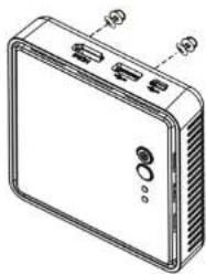
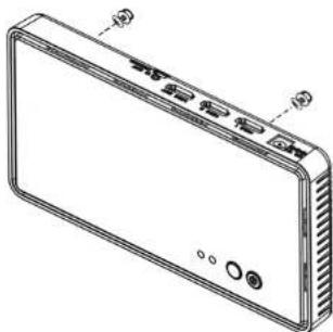
Step 5: Mounting the devices to the wall
-
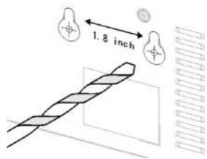
Refer the drawing of the bottom page that have relative position of the main holes and attach this paper on wall.
-
Place WHDI DEVICE main holes over the protruding screws and slide down into position.
natural_image
Line drawing of a rectangular electronic device with ports and ventilation slots (no text or symbols)-
Drill pilot holes.
-
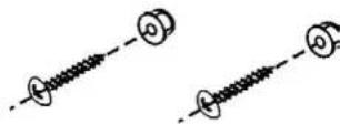
Insert the supplied two Anchors into the wall.

- Insert two screws into the anchors. Leave 1/8" length for mounting the Transmitter or receiver.
Supported Resolution Troubleshooting
| Problem Solution | |
| The device power indicator LED doesn't light up. | ·Check if the power plugs of TRANSMITTER/RECEIVER are properly inserted into a functioning power outlet. |
| No video is displayed on your TV screen. | ·Verify that the proper cables have been selected and installed between the Transmitter input and your High Definition device output.·On your TV side (connected to the RICO-VIR), select the HDMI as input source.·Verify the POWER LED and SOURCE LED indicator of device.Power LED Flashing in BlueOSD displayed: 📄 Ensure the transmission range between the transmitter and the receiver is NOT over 66 feet ( OS-line of sight) transmission distance.- Try to move the transmitter closer to the receiver.POWER LED in Solid Blue + Slow and Flashing SOURCE LEDOSD displayed: 📄 Ensure your video resolution and frame rate is recognized/ supported and within the transmission range.- Connect the source device to your TV to check and modify the video format compatibility.- Check if your video resolution with HDMI input from your device is set among 1080p, 1080i, /20p, 5/6p, or 480p. Please refer Chapter 5 for the detail supported Resolution.POWER LED in Solid Blue STATUS LED Flash QuicklyOSD displayed: 📄 Ensure the proper cables are connected between the transmitter and your AV source devices.- Ensure your source devices connected to the device transmitter are powered on.- Ensure the proper cables are connected between the receiver and your 2nd HIDTV near the receiver. |
| Poor picture quality or intermittent video. | ·Check if your video resolution with HDMI input from your device is either 1080o, 1080i, /20o, 5/6p, or 480o. Please refer to the "Supported Resolution" chapter where the video frame rate from your HD AV device device can support is defined.·Ensure the transmission distance is less than 66 feet ( OS). |
| No audio. | ·Check your TV's volume is properly set and not set in ,MUTE* mode.·Check if your source player's audio volume has been turned up..·Ensure the bit rate of audio from the source device can be supported by device. Please refer to the details in Chapter 6, Audio Bit Rate Support. |
| IR Blaster can't control Source device. | ·Check where is IR sensor of Source device. Make sure IR Blaster sensor is close and straight to Source device's IR sensor. Please refer Chapter 3, step 3 for reference setup.·Change IR Blaster frequency to meet Source device's requirement. See the page 20 for the IR blaster frequency switch. |
If the SOURCE LED continues to blink in blue (slower than "no signal" mode); OSD display: , and there is no video displayed or the video quality suffers, it indicates that the video frame rate from your A/V source device is not supported. Ensure that the consumer timing of your HD device is compliant with the standard listed below:
| Video Format Timings Resolution Support | ||
| Primary CFA Video Timing | ||
| 640x480p @ 59.94 / 60Hz | 480p | YHS |
| 720x480p @ 59.94Hz YES | ||
| 720x480p @ 60Hz YES | ||
| 720x576p @ 50Hz 576p YES | ||
| 1280x770p @ 50Hz | 720p | YHS |
| 1280x720p @ 59.94 / 60Hz YES | ||
| 1920x1080i @ 50Hz | 1080i | YES |
| 1920x1080i @ 59.94 / 60Hz | YES | |
| 1920x1080p @ 50Hz | 1080p / 60 | YES |
| 1920x1080p @ 59.94 / 60Hz | YES | |
| Secondary CFA Video Timing | ||
| 1920x1080p @ 23.98 / 24Hz | 1080p / 24 | YES |
| 1920x1080p @ 25Hz | YES | |
| 1970x1080p @ 79.97 / 30Hz | YES | |
| VESA Timing (DVI only) | ||
| 640x480 @ 59.94 / 72.80Hz/ | VGA | YES |
| 800x600 @ 60.317 / 72.188Hz | SVGA | YES |
| 1024x768 @ 60 / 70.069Hz | XGA | YES |
| 1280x768 @ 60 Hz | WXGA | YES |
| 1280x1024 @ 60 Hz | SXGA | YES |
| 1600x1200 @ 60 Hz | UXGA | YES |
Audio Bitrate Support Declaration of Conformity
• Digital Audio from HDMI inputs: Up to 6Mbit/s bit-rate support.
• Support AC3 and DTS.
- 2-channel PCM: 16\~24 bits audio sample with 32\~96KHz sampling rate as below:
| 2 Channel PCM 32KHz 44.1KHz 48KHz 96KHz | |||
| 16 bits YES YES YES YES | |||
| 74 bits Y=5 YES YES Y=5 |
Specifications
General data:
• Supported video resolution:
480p / 5/6p //20p / 1080i / 1080p
• Supported audio resolution:
up to 6 Mbps AC3 and DTS
• Max. transmission distance to 20 meters
• Integrated high performance antenna
- Latenz < 1 ms
• Frequency band 4.5 - 5.9 GHz
(including non-DFS and DFS frequency band)
• Power supply 100\~240 V AC / 5 V DC
- Operating temperature 0^ - 40^
Transmitter:
- 2x HDMI input
- 1x HDMI output
- 1x Infrared sensor
- Standby switch
- Source switch
• Dimensions: 182 x 96.5 x 31.5 mm - Weight:204g
Receiver:
- 1x HDMI output
- 1x Infrared sensor
- Standby switch
- Source switch
• Dimensions: 95 x 95 x 37.2 mm - Weigh: 176g
Note:
Weight and dimensions are not absolutely exact values.
Technical details can be changed at any time
(according to manufacturer) without prior notice.
This complies with the following directives / standards is confirmed:
Electromagnetic Compatibility Directive 2004/108/EG
EN 55013:2001+A1:2003+A2:2006
EN 55020:2007
EN 61000-3-2:2006 + A1:2009 + A2:2009
EN 61000-3-3:2008
Low Voltage Directive 2006/95/EG
EN 60065:2002+A1:2006+A11:2008
Notes
- Installation Installation
- Table of Contents Safety Instructions
- Introduction Overview
- Packing content
- Overview Overview
- Power Button with LED indicator
- Source LEDs
- Source Button
- DC IN
- POWER Button
- IR Button
- INFO Button
- Step 1: Setup the Transmitter
- Step 3: Setup the Blaster and IR Sensor S
- NOTE:
- Step 5: Mounting the devices to the wall
- Supported Resolution Troubleshooting
- Audio Bitrate Support Declaration of Conformity
- Specifications
- General data:
- Transmitter:
- Receiver:
- Notes
Brand : MEGASAT
Model : Wireless HD Sender
Category : Audio/Video Transmitter