GV‐SNVR0400F - Dictaphone Geovision - Free user manual and instructions
Find the device manual for free GV‐SNVR0400F Geovision in PDF.


| Product Type | Standalone Network Video Recorder (NVR) / Digital Dictaphone |
| Brand | Geovision |
| Model | GV-SNVR0400F |
| Video Channels | 4 channels |
| Video Compression | H.264 |
| Max. Recording Resolution | 1920 x 1080 per channel |
| Hard Drive Support | 1 SATA 3.5" HDD, up to 4 TB |
| Video Output | HDMI (up to 1080p) |
| Audio Output | 1 x Audio Out (speaker) |
| Network Interface | 1 x Gigabit Ethernet |
| USB Ports | 2 x USB 2.0 (1 front, 1 rear) |
| Power Supply | DC 19V, 3.42A, 65W |
| Power Consumption | 65 W (typical) |
| Dimensions (approx.) | 220 x 180 x 40 mm (8.7 x 7.1 x 1.6 in) |
| Weight (approx.) | 1.5 kg (3.3 lbs) without HDD |
| Operating Temperature | 0°C to 40°C (32°F to 104°F) |
| Key Features | Automatic camera setup, motion detection, PTZ control, remote access via web/mobile, email alerts, timeline playback, recording export to USB |
| Included Accessories | AC power cord, AC/DC adapter, screws for HDD, SATA cable, firmware CD, software CD, quick start guide, warranty card |
| Warranty | 1 year (standard, may vary by region) |
| Manufacturer | GeoVision, Inc., Taipei, Taiwan |
Frequently Asked Questions - GV‐SNVR0400F Geovision
User questions about GV‐SNVR0400F Geovision
0 question about this device. Answer the ones you know or ask your own.
Ask a new question about this device
Download the instructions for your Dictaphone in PDF format for free! Find your manual GV‐SNVR0400F - Geovision and take your electronic device back in hand. On this page are published all the documents necessary for the use of your device. GV‐SNVR0400F by Geovision.
USER MANUAL GV‐SNVR0400F Geovision
natural_image
Exterior view of two black GEUs (HDMI) networking equipment with ventilation grilles and ports, no visible text or symbols on the device surfaces.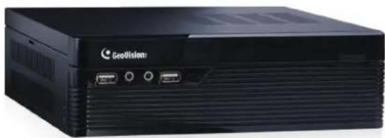
natural_image
Front view of a black GeoVision computer chassis with ports and ventilation slots (no visible text or symbols beyond branding)
natural_image
Abstract graphic of a blue eye with radiating light patterns, surrounded by concentric gray rings and striped background (no text or symbols)
GeoVision Inc
© 2016 GeoVision, Inc. All rights reserved.
Under the copyright laws, this manual may not be copied, in whole or in part, without the written consent of GeoVision.
Every effort has been made to ensure that the information in this manual is accurate. GeoVision, Inc. makes no expressed or implied warranty of any kind and assumes no responsibility for errors or omissions. No liability is assumed for incidental or consequential damages arising from the use of the information or products contained herein. Features and specifications are subject to change without notice.
Note: No memory card slot or local storage function for Argentina.
GeoVision, Inc.
9F, No. 246, Sec. 1, Neihu Rd.,
Neihu District, Taipei, Taiwan
Trademarks used in this manual: GeoVision, the GeoVision logo and GV series products are trademarks of GeoVision, Inc. Windows is the registered trademarks of Microsoft Corporation.
December 2016
Preface
Welcome to the GV-SNVR System User's Manual.
The GV-SNVR System has a series of models designed to meet different needs. This manual is designed for the following models and firmware versions:
| Models Firmware Version | |
| GV-SNVR0411 V2.10 | |
| GV-SNVR0400F V1.11 | |
| GV-SNVR1600 V1.21 |
Caution
● The GV-SNVR System is designed only for indoor usage.
Contents
Chapter 1 Introduction.... 1
1.1 Features....2
1.2 Models 3
1.3 Packing List and Package....3
1.3.1 GV-SNVR Single Package 3
1.3.2 GV-SNVR Bundled Package 5
GV-SNVR0400F 5
1.4 Compatible Products and System Requirements....6
1.4.1 Supported GV-IP Cameras....6
1.4.2 Supported GeoVision Applications 7
1.4.3 System Requirements 8
1.5 Options 9
1.6 Overview....10
1.6.1 Front View 10
1.6.2 Rear View....13
Chapter 2 Getting Started.... 16
2.1 Installation....16
2.1.1 GV-SNVR0411 16
2.1.2 GV-SNVR0400F 18
2.1.3 GV-SNVR1600 20
2.2 Connecting the GV-SNVR....23
2.2.1 Network Connection for GV-SNVR1600 25
2.3 Setting Up GV-IP Camera....26
2.3.1 Automatically Setting Up GV-IP Camera 26
2.3.2 Manually Connecting GV-IP Cameras....28
2.3.3 Manually Connecting Third-Party IP Camera....29
2.3.4 Changing Camera IP Address and Assigning Channels....31
2.4 Formatting the Hard Drive....32
2.5 Main Screen....34
2.6 Enabling Recording....36
2.7 Playing Back Video 36
2.8 Live Monitoring....37
2.8.1 Snapshot 37
2.8.2 Audio 38
2.8.3 PTZ Control 38
Chapter 3 System Configuration 41
3.1 Camera....41
3.2 Recording....43
3.3 Network....44
3.4 Storage 48
3.5 Display 49
3.6 Service....51
3.6.1 Connecting GV-SNVR with GV-Center V2 and GV-Vital Sign Monitor. 51
3.6.2 Connecting GV-Eye to GV-SNVR....53
3.7 System....55
Chapter 4 Video Playback 59
4.1 Timeline Player ....59
4.2 recording Backup 61
Chapter 5 Remote Access to the GV-SNVR 62
5.1 Accessing through Web browser 63
5.1.1 Live View Screen 64
5.1.2 Snapshot of Live Video....66
5.1.3 Picture-in-Picture View 67
5.1.4 Picture-and-Picture View 68
5.1.5 Digital PTZ Control 69
5.1.6 Fisheye View 70
5.2 Accessing through Mobile Device 73
5.3 Accessing through GV-Edge Recording Manager....73
5.4 Accessing through GV-Control Center 74
Chapter 6 Advanced Applications....75
6.1 Upgrading System Firmware 75
6.2 Using the GV-IP Device Utility....76
6.2.1 Looking up the IP Address....76
6.2.2 Accessing the Live View....76
6.2.3 Upgrading System Firmware 77
6.2.4 Backing up and Restoring Settings 78
Appendix....80
Chapter 1 Introduction
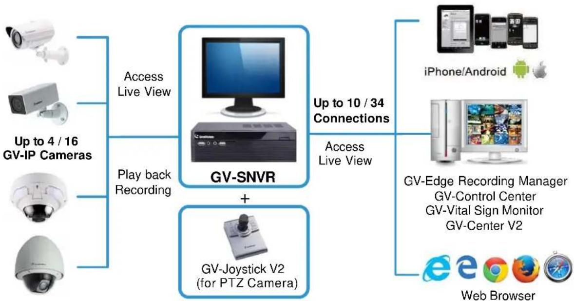
GV-SNVR is an H.264/H.265 linux-embedded Standalone Network Video Recorder which records video files directly to the internal hard drive, supporting up to 4 / 16 channels of GV-IP Cameras for network surveillance. With the feature of a Full HD HDMI video output, the GV-SNVR eliminates the need for a separate PC to view and play back video from the unit. Its USB ports allow you to connect a USB flash drive to import or export system settings, update firmware, save snapshot files and back up video in AVI format.
Optionally, you can connect a GV-Joystick V2 to control PTZ cameras. Moreover, you can remotely access the live view through mobile devices or Web browsers with advanced video features.
flowchart
graph TD
    A["Camera"] --> B["GV-SNVR"]
    C["Camera"] --> B
    D["Camera"] --> B
    E["Camera"] --> B
    F["Up to 4 / 16 GV-IP Cameras"] --> B
    G["Play back Recording"] --> B
    H["GV-Joystick V2 (for PTZ Camera)"] --> B
    I["Up to 10 / 34 Connections"] --> B
    J["Access Live View"] --> B
    K["Access Live View"] --> B
    L["iPhone/Android"] --> M["Mobile Device"]
    N["Android"] --> O["Mobile Device"]
    P["Mobile Device"] --> Q["Mobile Device"]
    R["Mobile Device"] --> S["Mobile Device"]
    T["Mobile Device"] --> U["Mobile Device"]
    V["Mobile Device"] --> W["Mobile Device"]
    X["Mobile Device"] --> Y["Mobile Device"]
    Z["Mobile Device"] --> AA["Mobile Device"]
    AB["Mobile Device"] --> AC["Mobile Device"]
    AD["Mobile Device"] --> AE["Mobile Device"]
    AF["Mobile Device"] --> AG["Mobile Device"]
    AH["Mobile Device"] --> AI["Mobile Device"]
    AJ["Mobile Device"] --> AK["Mobile Device"]
    AL["Mobile Device"] --> AM["Mobile Device"]
    AN["Mobile Device"] --> AO["Mobile Device"]
    AP["Mobile Device"] --> AQ["Mobile Device"]
    AR["Mobile Device"] --> AS["Mobile Device"]
    AT["Mobile Device"] --> AU["Mobile Device"]
    AV["Mobile Device"] --> AW["Mobile Device"]
    AX["Mobile Device"] --> AY["Mobile Device"]
    AZ["Mobile Device"] --> BA["Mobile Device"]
    BB["Mobile Device"] --> BC["Mobile Device"]
    BD["Mobile Device"] --> BE["Mobile Device"]
    BF["Mobile Device"] --> BG["Mobile Device"]
    BH["Mobile Device"] --> BI["Mobile Device"]
    BJ["Mobile Device"] --> BK["Mobile Device"]
    BL["Mobile Device"] --> BM["Mobile Device"]
    BN["Mobile Device"] --> BO["Mobile Device"]
    BP["Mobile Device"] --> BQ["Mobile Device"]
    BR["Mobile Device"] --> BS["Mobile Device"]
    BT["Mobile Device"] --> BU["Mobile Device"]
    BV["Mobile Device"] --> BW["Mobile Device"]
    BX["Mobile Device"] --> BY["Mobile Device"]
    BZ["GV-Edge Recording Manager\nGV-Control Center\nGV-Vital Sign Monitor\nGV-Center V2"] --> BX
    CA["e"] --> PX["e"]
    CB["b"][b] --> DX["b"]
    DB["d"] --> DX["d"]
    DB["D"] --> DX["D"]
    DB["E"] --> DX["E"]
    DB["F"] --> DX["F"]
    DB["G"] --> DX["G"]
    DB["H"] --> DX["H"]
    DB["I"] --> DX["I"]
    DB["U"] --> DX["U"]
    DB["V"] --> DX["V"]
    DB["W"] --> DX["W"]
    DB["X"] --> DX["X"]
    DB["Y"] --> DX["Y"]
    DB["Z"] --> DX["Z"]
    DB["W"] --> DX["W"]
Figure 1-1
Note: H.265 video compression is only supported by GV-SNVR0411.
1.1 Features
• 4-Channel video recording (for GV-SNVR0411 / 0400F)
• 16-Channel video recording (for GV-SNVR1600)
• Automatic search and set-up for GV-IP Cameras
• Support for third-party IP cameras through ONVIF and RTSP (for GV-SNVR0411)
• 4-Port PoE (IEEE 802.3af) for camera connection (for GV-SNVR0411)
- Video Resolution
| Model | Resolution |
| GV-SNVR0411 | Up to 3840 x 2160 per channel * |
| GV-SNVR0400F | Up to 1920 x 1080 per channel * |
| GV-SNVR1600 | Up to 2592 x 1944 for the first channel *Up to 1920 x 1080 per channel * |
- Dual streams support
• Continuous, motion and scheduled recordings - Timeline playback
• Multi-channel playback
• Display of HDD status and system temperature
• DST (Daylight Saving Time) support
• NTP (Network Time Protocol) support
• GeoVision DDNS server support
• E-mail notification for recording error and password retrieval - Recording export
- Remote live view through Web browser
• PTZ control using GV-Joystick V2 or on-screen panel - HDD Storage
| Model | Storage |
| GV-SNVR0411 | 1 SATA HDD drawer (3.5") for up to 8 TB storage |
| GV-SNVR0400F | 1 SATA HDD drawer (3.5") for up to 4 TB storage |
| GV-SNVR1600 | 4 SATA HDD drawer (3.5") for up to 16 TB storage |
• Smart device access (iOS and Android)
• Support for 13 languages
*The resolutions of stream 1 and 2 both must meet the requirements noted in Appendix C.
1.2 Models
The GV-SNVR has the following models:
| GV-SNVR0411GV-SNVR0400F | - Supports 1 SATA HDD (3.5")- Records up to 4 IP channels |
| GV-SNVR1600 | - Supports 4 SATA HDD (3.5")- Records up to 16 IP channels |
1.3 Packing List and Package
You can choose to purchase a GV-SNVR0411 / 0400F / 1600 package or a GV-SNVR0400F bundled package which includes 4 GV-Target IP Camera of your choice, and with or without a GV-PoE switch.
1.3.1 GV-SNVR Single Package
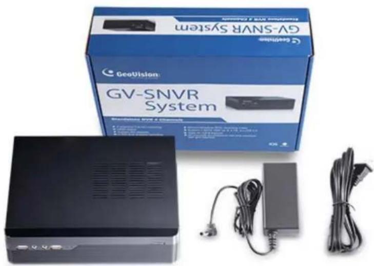
GV-SNVR0411
natural_image
Exterior view of a black Gaming PC with attached hardware components including a charger, mouse, and cable (no visible text or symbols)- GV-SNVR0411
- AC Power Cord
- AC/DC Adapter (DC 52V, 1.38 A, 72 W)
- SATA Cable
- HDD Power Cable
- Screw x 4 (for HDD)
- Rubber Foot x 4 (for HDD)
- USB Mouse
- Firmware CD/DVD
- Software CD/DVD
- Warranty Card
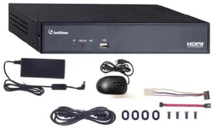
GV-SNVR0400F
- GV-SNVR0400F
- AC Power Cord
- AC/DC Adapter (DC 19V, 3.42A, 65 W)
- Screw x 6 (for HDD)
- SATA Cable
- Firmware CD/DVD
- Software CD/DVD
- Quick Start Guide
- Warranty Card
GV-SNVR1600
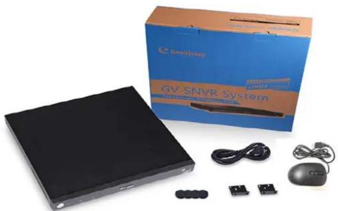
natural_image
Product photo of a device labeled 'GV SNVR System' with a blue box, mouse, and small electronic components (no visible text beyond branding)- GV-SNVR1600
- AC Power Cord
- SATA Cable x 4
- HDD Mounting Bracket Kit (4 pairs and 32 screws included)
- Rack Mount Kit (2 L-shaped brackets and 6 screws included)
- Rubber Foot x 4
- USB Mouse
- Firmware CD/DVD
- Software CD/DVD
- Quick Start Guide
- Warranty Card
1.3.2 GV-SNVR Bundled Package
GV-SNVR0400F
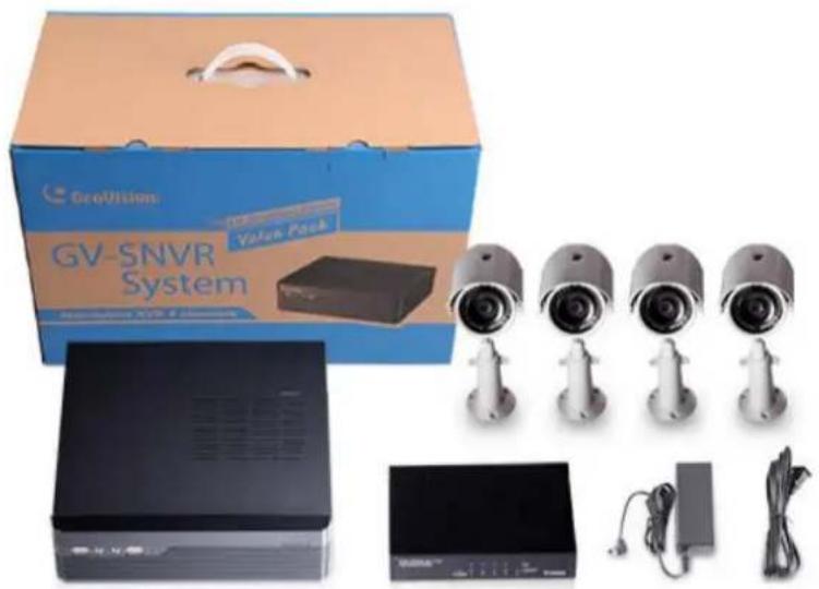
natural_image
Product photo of a GV-SNVR System with multiple security camera modules and a branded box (no visible text or symbols on main components)- GV-SNVR0400F Package x 1
- Target IP Camera x 4
- GV-POE0400 x 1
Note: For the Target IP Camera, select any 4 models from GV-EBL1100 / 2100, GV-EBX1100 / 2100, GV-EDR1100 / 2100, GV-EFD1100 / 2100. For more information, contact our sales representatives.
1.4 Compatible Products and System Requirements
1.4.1 Supported GV-IP Cameras
7KH□* 9□6195 □LV□FRP SDNLEOH□Z LINK□WKH□IRCORZLQJ□* 9□,3□&DP HUDV□□
• * 9□7DUJHW□6HULHV□,3□&DP HUDV□) LUP Z DUH□9□□□□RU□CDNHU□
• * 9□6' □□□□□□□□6□□) LUP ZDUH□9 □□□□□RU□CDWHU□□
• \$000WKH□RWKHU□* 9□,3 □&DP HUDV□□) LUP ZDUH□9 □□□□RUVODWHU□EXCEPT□WKH□P RGHCV□EHORZ□
1.4.2 Supported GeoVision Applications
7KH□* 9□6195 □LV□FRP SDWLECH□Z LWK□WKH□IRCCRZ LQJ □DSSQLFDNLRQV□□
For GV-SNVR0411
• * 9□(GJH□5 HFRUGLQJ□0 DQDJHU□: LQGRZV□9HUVLRQ□9 □□□□□□□□RUDNHU□
• * 9□&RQWUR□&HQWHU□□9 □□□□□□□□RU□ODNHU□□ □
• * 9□&HQWHU□9□□9□□□□□□RU□○DWHU□□
• * 9□9LWD□6LJQ□0 RQLWRU□9 □□□□□□RU□0DNHU□□
• * 9□( \H□□9□□□□RU□CDWHU□□
□
Note□+ □□□□□YLGHR□FRP SUHVV□RQ□LV□RQ□ VXSSRU□HG□E□* 9□( \ H□9 □□□□□RU□D□VH□□□ □
For GV-SNVR0400F / 1600
• * 9□(GJH□5 HFRUGLQJ□0 DQDJHU□□: LQGRZV□9HUVLRQ□9□□□□□□□□□RUDDHNHU□□
• * 9□&RQWUR□&HQNHU□9 □□□□□□□□RU□D NHU□□ □
• * 9□&HQWHU□9□□□9□□□□□□RU□□DVHU□□
• * 9□9LWD□6LJQ□0 RQLNRU□□9 □□□□□□RU□CDNHU□□
• * 9□( \ H□□9 □□□□RU□0DWHU□□
1.4.3 System Requirements
Recommended Hard Disks
GV-SNVR0411 supports 1 SATA HDD (3.5") with up to 8 TB capacities, GV-SNVR0400F supports 1 SATA HDD (3.5") with up to 4 TB capacities, and GV-SNVR1600 supports 4 SATA HDD (3.5") with total up to 16 TB capacities. For system efficiency, it is recommended to use the enterprise-level hard disk drives instead of desktop-level or green HDD. For tested hard disk drives, see Appendix.
Note: The GV-SNVR does not support the 2.5" SATA HDD.
Supported Web Browsers
- Internet Explorer 8 or later
- Google Chrome
- Mozilla Firefox
• Safari (Only supported by GV-SNVR0411)
• Microsoft Edge (Only supported by GV-SNVR0411)
1.5 Options
Optional devices can expand your GV-SNVR's capabilities and versatility. Contact your dealer for more information.
| GV-Joystick V2 | The GV-Joystick V2 facilitates the PTZ camera control. It can be plugged into the GV-SNVR for independent use to empower the operation of PTZ cameras. |
| GV-POE Switch | The GV-POE Switch is designed to provide power along with network connection for IP devices. The GV-POE Switch is available in various models with different numbers and types of ports. |
| Slide Rail Kit | The Slide Rail Kit is used to mount a rail for the GV-SNVR1600 in a 19" cabinet. |
1.6 Overview
1.6.1 Front View
1.6.1.1 GV-SNVR0411
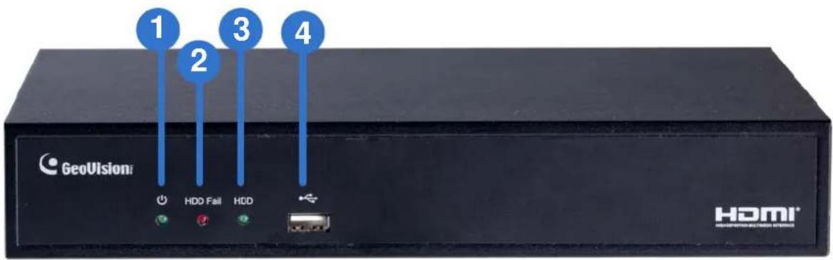
Figure 1-1
| No. | Name Function | |
| 1 | Power LED | Shows constant Green when the power is supplied for the device. |
| 2 | HDD Fail LED | Shows constant red when the following situations occur:No hard drive is installed.The hard drive is not formatted.The hard drive fails. |
| 3 | HDD LED | Blinks Green when the HDD is writing or reading data. |
| 4 | USB 2.0 Port | Connects to a keyboard, mouse, USB flash drive or GV-Joystick V2. |
1.6.1.2 GV-SNVR0400F
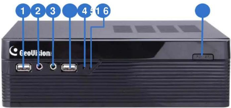
Figure 1-2
| No. | Name Function | |
| 1 | USB 2.0 Port | Connects to a keyboard, mouse, USB flash drive or GV-Joystick V2. |
| 2 | Audio In Not functional. | |
| 3 | Audio Out | Connects to a speaker. |
| 4 | Power LED | Shows constant blue when the power is supplied for the device. |
| 5 | HDD Error LED | Shows constant red when the following situations occur:No hard drive is installed.The hard drive is not formatted.The hard drive fails. |
| 6 | Power Button | Turns on/off the power. |
1.6.1.3 GV-SNVR1600
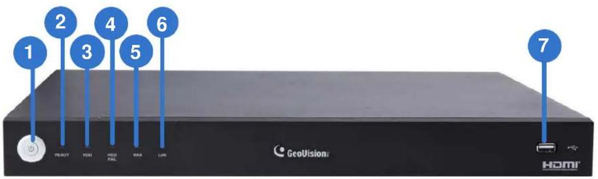
Figure 1-3
| No. | Name Function | |
| 1 | Power Button Turns on/off the power. | |
| 2 | Power LED | Shows constant blue when the power is supplied for the device. |
| 3 | HDD Status LED | Flashes blue when the hard drive is writing or reading data. |
| 4 | HDD Error LED | Shows constant red when the following situations occur:No hard drive is installed.The hard drive is not formatted.The hard drive fails. |
| 5 | WAN LED | Flashes blue when the WAN port is receiving activity. |
| 6 | LAN LED | Flashes blue when the LAN port is receiving activity. |
| 7 | USB 2.0 Port | Connects to a keyboard, mouse, USB flash drive or GV-Joystick V2. |
1.6.2 Rear View
1.6.2.1 GV-SNVR0411
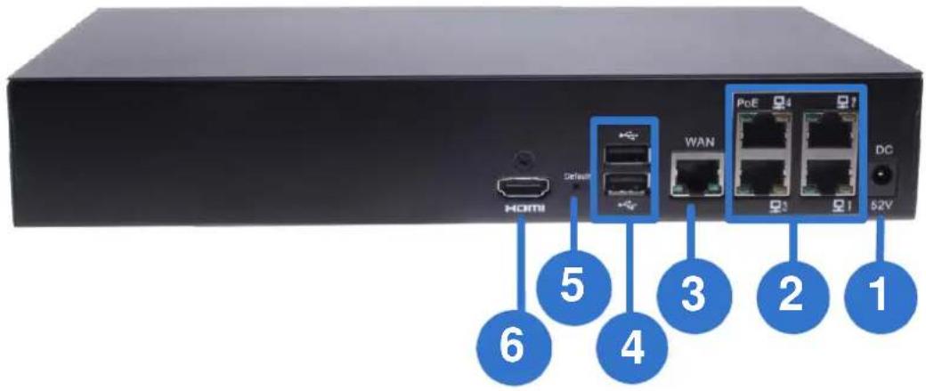
Figure 1-4
| No. | Name Function | |
| 1 | DC 52 V (Power Input) | Connects to power supply. |
| 2 | Megabit PoE Ports | Connects to cameras, delivering power and network connection to the cameras. |
| 3 | WAN | Connects to the network. |
| 4 | USB 2.0 Port | Connects to a keyboard, mouse, USB flash drive or GV-Joystick V2. |
| 5 | Default Button | Restores the device to default settings. Press the button for 15 seconds to load default. |
| 6 | HDMI Output | Connects to a HD TV. |
1.6.2.2 GV-SNVR0400F
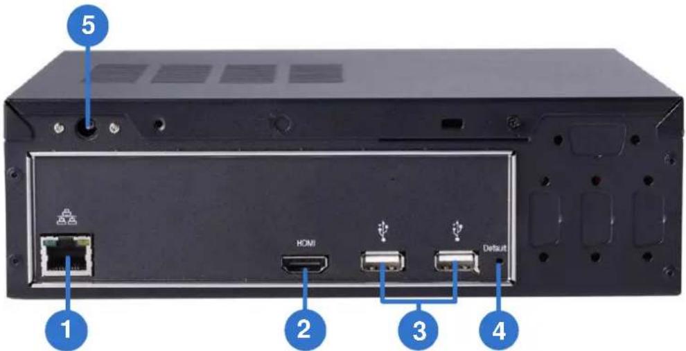
Figure 1-5
| No. | Name Function | |
| 1 | Gigabit Ethernet Port | Connects to the network. |
| 2 | HDMI Output | Connects to a HD TV. |
| 3 | USB 2.0 Port | Connects to a keyboard, mouse, USB flash drive or GV-Joystick V2. |
| 4 | Default Button | Restores the device to default settings. Press the button for 15 seconds to load default. |
| 5 | Power Input Connects | to power supply. |
1.6.2.3 GV-SNVR1600
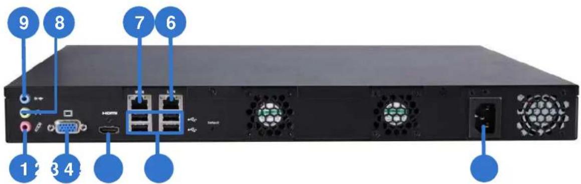
Figure 1-6
| No. | Name Function | |
| 1 | Audio Microphone In Port | Not functional. |
| 2 | VGA Monitor Output | Connects to a VGA monitor. |
| 3 | HDMI Port | Connects to a HD TV. |
| 4 | USB 2.0 Port x 4 | Connects to a keyboard, mouse, USB flash drive or GV-Joystick V2. |
| 5 | Power Input | Connects to power supply. |
| 6 | Gigabit Ethernet Port (LAN) | Connects to the network. |
| 7 | Gigabit Ethernet Port (WAN) | Connects to the network. |
| 8 | Audio Line Out Port | Connects to a headphone. |
| 9 | Audio Line Out Port | Connects to a speaker. |
| Note: When the two Ethernet ports (No. 6 and No. 7) are used together, one is LAN port and the other is WAN port. | ||
Chapter 2 Getting Started
2.1 Installation
The GV-SNVR uses SATA hard drive for video data storage. Before recording, be sure to install the hard drive.
2.1.1 GV-SNVR0411
Installing the Hard Drive
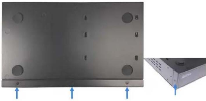
Follow the steps below to install the hard drive to GV-SNVR0411.
- Unscrew three screws on the bottom and two screws on the sides; then remove the cover.
natural_image
Exterior view of a black metal enclosure with circular holes and mounting points, shown from two angles (no text or symbols)Figure 2-1
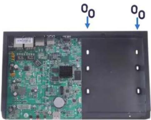
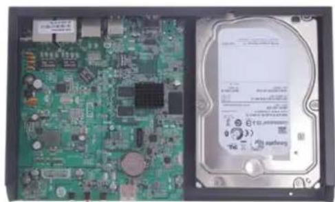
- Place the supplied rubber foots on four of the six oval holes and place the hard drive in the drive drawer as below by aligning the four holes.
natural_image
Interior view of an electronic device showing a green circuit board with multiple components and two blue arrows pointing to the top panel (no text or symbols on the board itself)Figure 2-2
natural_image
Interior view of a hard disk drive showing internal circuit board and rear hard drive (no text or symbols visible)Figure 2-3
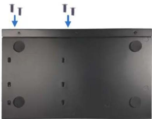
- Secure the hard drive from the back of the drawer using the supplied 4 screws.
natural_image
Metal plate with circular holes and two downward arrows indicating force or displacement (no text or symbols)Figure 2-4
- Connect the SATA Power Cable and Data Cable to the hard drive.
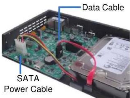
Figure 2-5
- Assemble the cover with the device by tightening the screws on the bottom and sides. panel (Figure 2-1).
The hard drive is now ready to use.
2.1.2 GV-SNVR0400F
Installing the Hard Drive
Follow the steps below to install the hard drive to GV-SNVR0400F.
- Unscrew the two screws on the rear panel and remove the cover.
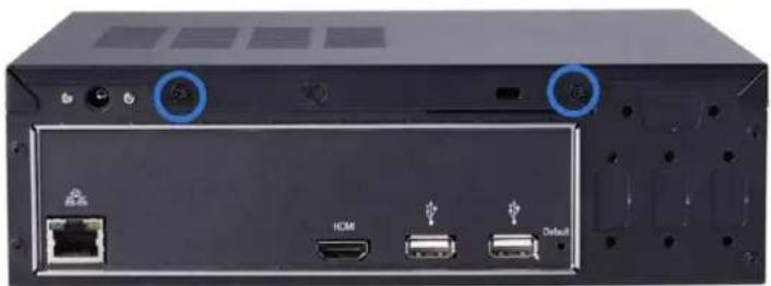
natural_image
Back panel of a computer drive showing ports and connectors (no readable text or symbols)Figure 2-6
- Unscrew the drive drawer and take it out from the device.
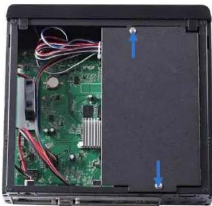
natural_image
Interior view of an electronic device showing a green circuit board, power cord, and cable (no text or symbols visible)Figure 2-7
- Place the hard drive in the drive drawer as below by aligning the three holes.
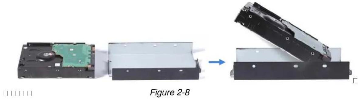
natural_image
Diagram showing a device being processed into a hard drive, with no visible text or symbols on the components.- Secure the hard drive with the drive drawer using the supplied 6 screws (3 screws on each side).
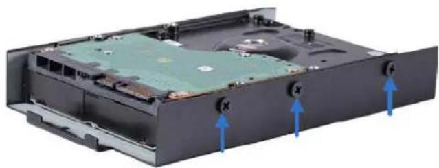
natural_image
Interior view of a computer drive chassis showing internal components and mounting holes (no text or symbols visible)Figure 2-9
- Connect the SATA Power Cable and Data Cable to the hard drive.
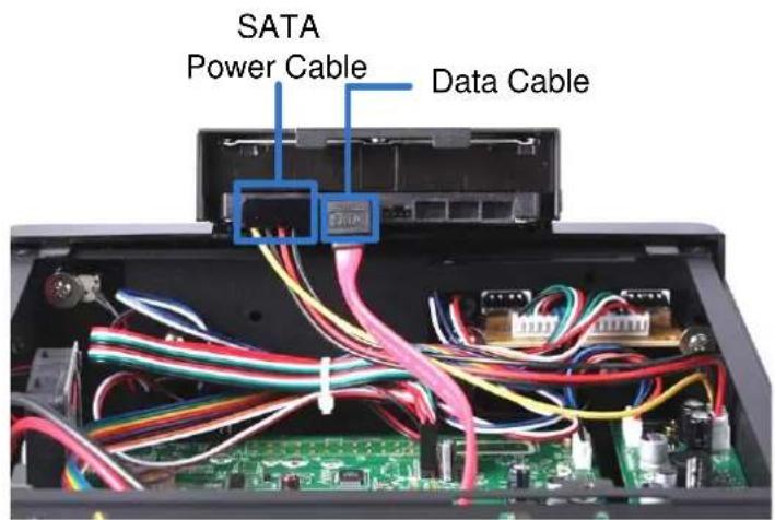
Figure 2-10
- Put the drive drawer back in the device and secure the two screws on the drive drawer (Figure 2-7).
- Assemble the cover with the device by tightening the screws on rear panel (Figure 2-6).
The hard drive is now ready to use.
2.1.3 GV-SNVR1600
Installing the Hard Drive
Follow the steps below to install the hard drive to the GV-SNVR1600.
- Loosen the 6 screws and remove the cover.

natural_image
Back panel of a black server rack with ports, switches, and ventilation fans (no visible text or labels)Figure 2-11
- Assemble the mounting brackets with the hard drive and tighten the screws on both sides.
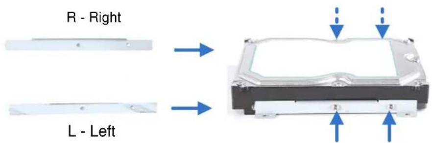
Figure 2-12
Note: Each mounting bracket is labeled L or R for recognition. Align the mounting bracket with the holes on the hard drive and make sure it is secured to the correct side.
- Align the mounting bracket with the holes inside the unit.
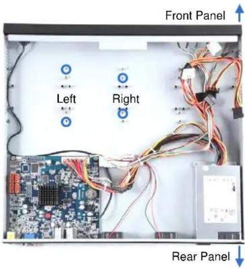
Figure 2-13
- Tighten the 4 screws on the side of the hard drive.
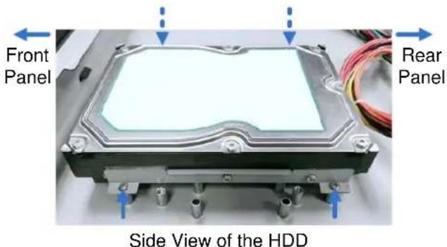
Figure 2-14
- Connect the SATA Power Cable and Data Cable to the hard drive.
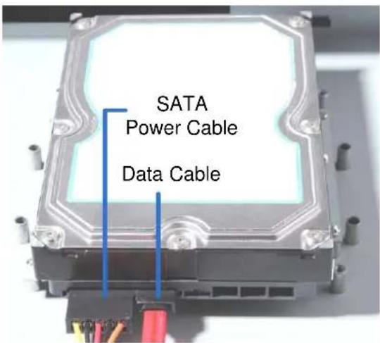
Figure 2-15
- To install more HDDs, repeat the steps above.
- Place the cover back and tighten the screws.
The hard drive is now ready for use.
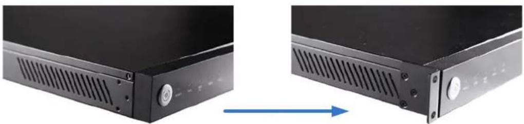
Installing the L-Shaped Brackets
Tighten the 6 screws to secure and attach the 2 L-shaped brackets to each side of GV-SNVR1600.
natural_image
Two black server rack components with ventilation slots, one showing a blue arrow indicating direction (no text or symbols)Figure 2-16
2.2 Connecting the GV-SNVR
Follow the steps below to connect the GV-SNVR.
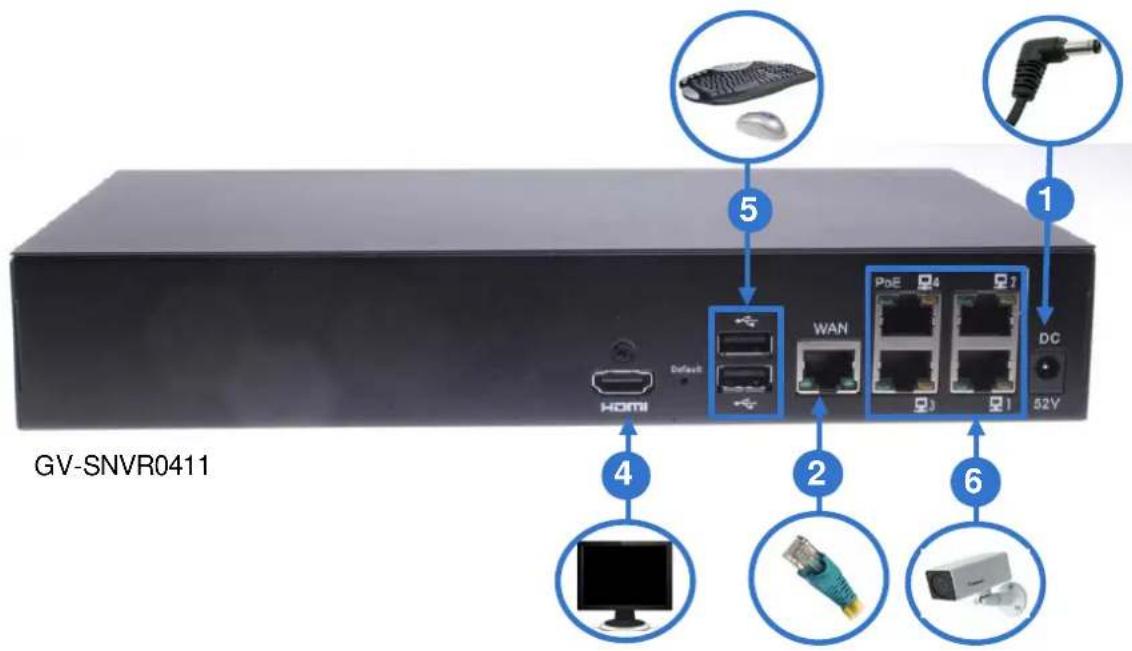
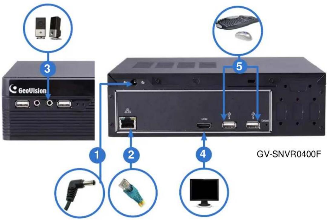
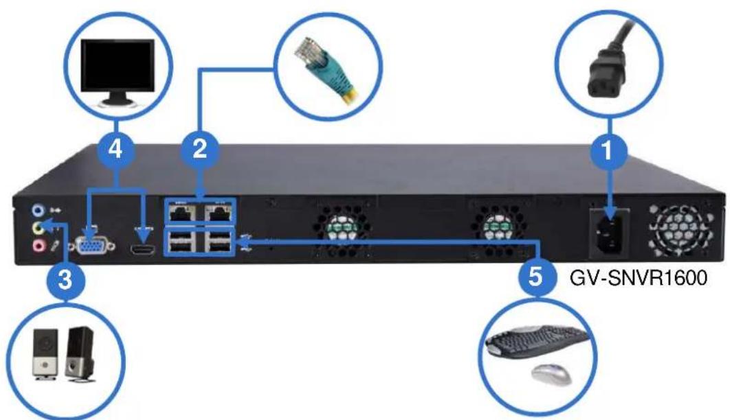
Figure 2-17
- Connect the GV-SNVR to power.
- Connect the GV-SNVR to the LAN port using the Ethernet cable.
- Connect a speaker to the Audio Line Out port.
- Connect a HDTV to HDMI connector for video/audio output. For GV-SNVR1600, optionally connect t a VGA monitor to the D-Sub connector for dual-monitor display.
-
Connect the mouse and the keyboard to the USB ports.
-
Only for GV-SNVR0411, connect cameras to the GV-SNVR using Ethernet cables. Press the power button to turn on the GV-SNVR.
Note:
- The GV-SNVR is DHCP enabled. When it is connected to the network, it will be automatically assinged an IP address.
- For GV-SNVR1600, the monitor used for VGA output must be capable of having a screen resolution of 1080p. For GV-SNVR0411, when you configure the camera's video resolution to 4K, be sure your monitor is a 4K-capable monitor.
- The audio line out port is not supported by GV-SNVR0411.
2.2.1 Network Connection for GV-SNVR1600
There are two network ports, LAN and WAN, for the GV-SNVR1600. If both network ports are used simultaneously, only the WAN port can be connected to the Internet. Therefore, it is recommended to connect the devices as below.
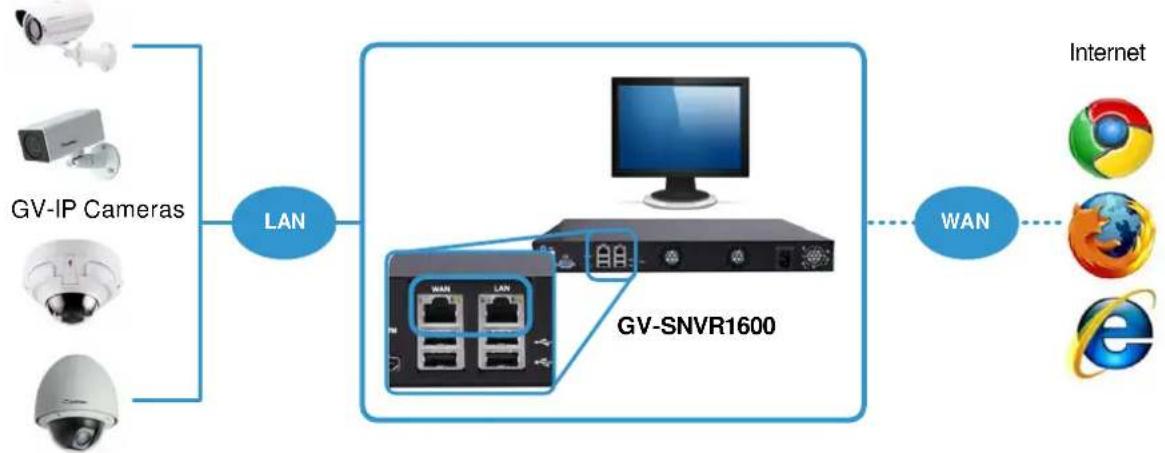
flowchart
graph LR
    A["GV-IP Cameras"] -->|LAN| B["GV-SNVR1600"]
    C["Internet"] -->|WAN| D["e"]
    E["Internet"] -->|WAN| F["Internet"]
    G["Internet"] -->|WAN| H["Internet"]
Figure 2-18
- Connect GV-IP Cameras to the GV-SNVR1600 through the LAN port.
- Connect GV-SNVR1600 to the Internet through the WAN port.
Note: When the LAN and WAN ports are used together, the Auto Search function is only supported by the LAN port. To connect to GV-IP Cameras under the WAN, you can add the cameras manually.
IMPORTANT: It is required to divide LAN and WAN networks into different subnets or segments; otherwise, your network will fail. For details, see 3.3 Network.
2.3 Setting Up GV-IP Camera
After installing the IP cameras under the same LAN with the GV-SNVR, you can now add the cameras to GV-SNVR.
2.3.1 Automatically Setting Up GV-IP Camera
To automatically set up the IP cameras, follow the steps below.
- Power on the GV-SNVR. It automatically searches and lists the IP cameras under the same LAN.
- You are prompted with a dialog box asking if you want to automatically assign IP address. The automatic assignment will only apply on the cameras with IP address 192.168.0.10.
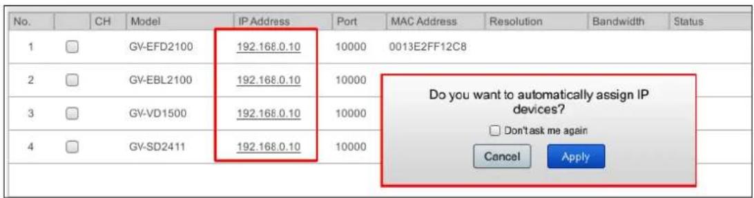
Figure 2-19
- Click Apply. The GV-SNVR assigns unused IP addresses to the cameras in an ascending numerical order and enables the connection.
| No. | CH | Model | IP Address | Port | MAC Address | Resolution | Bandwidth | Status | |
| 1 | ✓ | 01 | GV-EFD2100 | 192.168.0.2 | 10000 | 0013E2FF12C8 | H264:1280x1024 H264:320x256 | 0.7Mbps | Connected |
| 2 | ✓ | 02 | GV-EBL2100 | 192.168.0.3 | 10000 | 0013E2FF143D | H264:1920x1080 H264:448x252 | 5.0Mbps | Connected |
| 3 | ✓ | 03 | GV-VD1500 | 192.168.0.4 | 10000 | 0013E2FF0E87 | H264:1280x1024 H264:320x256 | 6.2Mbps | Connected |
| 4 | ✓ | 04 | GV-SD2411 | 192.168.0.5 | 10000 | 0013E2FF1B3F | H264:1920x1080 H264:448x252 | 2.7Mbps | Connected |
Figure 2-20
Upon successful connection, the status displays “Connected”, with the resolution and bandwidth being displayed in the correspondent columns. Close the Camera page to access the live view.
IMPORTANT:
- By default, GV-IP Cameras use the IP address 192.168.0.10. The GV-SNVR will automatically assign unused IP addresses to these cameras to avoid IP address conflict with others under the same LAN.
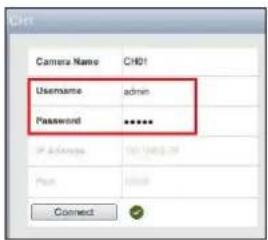
- The GV-SNVR connects to the IP cameras with the default ID and password admin. If the IP camera uses a different ID and password, click the Edit icon ✗ and type the correct login information.
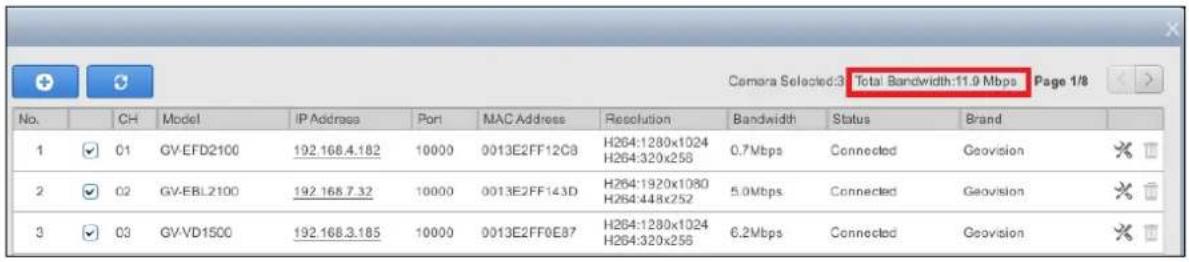
- The GV-SNVR supports a total bandwidth of up to 40 Mbps for GV-SNVR0411, up to 50Mbps for GV-SNVR0400F, and up to 100 Mbps for GV-SNVR1600. The total bandwidth can be found in the top-right corner of the camera list.
2.3.2 Manually Connecting GV-IP Cameras
You can manually add the GV- IP cameras to the camera list.
- On the Camera page, click the Add Cameras button.
- Type the IP Address, Username and Password of the desired IP camera. Keep the default Port 10000 or modify if necessary.
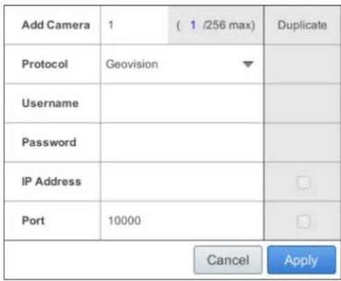
Figure 2-21
-
Click Apply to add the IP camera.
-
To add multiple cameras, repeat step 2. Type the number of cameras you want to create in the Add Camera column.
-
To duplicate camera with same IP address but different ports, type the IP address and click the Duplicate column of Port.
-
To duplicate camera with same port number but different IP addresses, type the port number and click the Duplicate column of IP Address.
-
To connect the GV-SNVR with the added cameras, click the box next to the CH column on the Camera page.
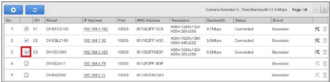
Figure 2-21-1
- To delete the added IP camera, click the Delete button ☐ of the camera on the Camera page.
2.3.3 Manually Connecting Third-Party IP Camera
The information in this section only applies to GV-SNVR0411. You can connect the third-party cameras through ONVIF and RTSP protocols.
Note:
- Exceptionally, GV-EBD4700 is an H.265 IP camera using ONVIF protocol for connection.
- ONVIF Protocol is only supported by H.264 third-party IP cameras.
-
RTSP Protocol is supported by H.264 / H.265 third-party IP cameras.
-
On the Camera page, click the Add Cameras button.
- Select the type of Protocol that is supported by your IP camera, ONVIF, or RTSP.
- Type the necessary infomation of the desired IP camera according to the protocol.
For ONVIF Protocol
A. Type the IP address, Username, and Password of the desired IP camera.
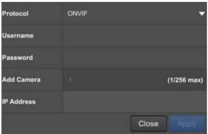
Figure 2-22
For RTSP Protocol
A. Type the Username and Password of the desired IP camera.
B. Select TCP or UDP under Type of Connection.
C. Type the RTSP URL to enable Stream1 and Stream2. For the RTSP command, consult the documentation of the third-party IP camera.
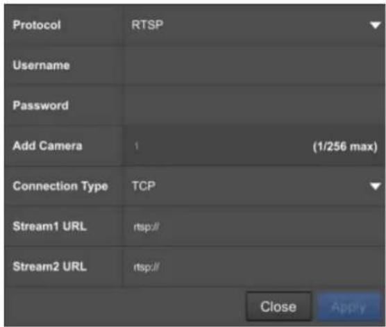
Figure 2-22-1
- Click Apply to add the IP camera.
- To connect the GV-SNVR with the added cameras, click the box next to the CH column on the Camera page.
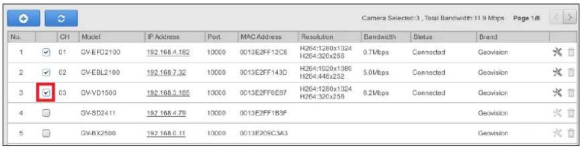
Figure 2-22-2
- To delete the added IP camera, click the Delete button ☐ of the camera on the Camera page.
2.3.4 Changing Camera IP Address and Assigning Channels
On the Camera page, you can change the IP address of the connected cameras by clicking on the IP address.
You can also re-assign the camera to another channel. For example, to change the camera on Channel 1, deselect the connected camera on Channel 1 and select another camera for connection. The selected camera is now assigned to Channel 1.
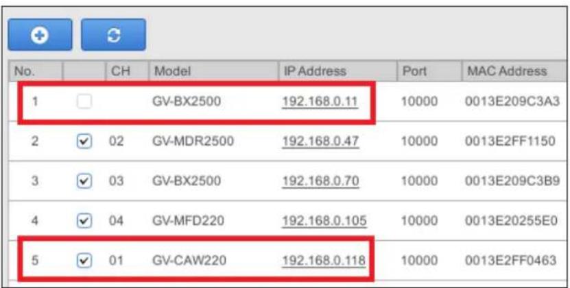
Figure 2-23
2.4 Formatting the Hard Drive
After installing the hard drive to GV-SNVR, you need to format the hard drive before enabling the monitoring.
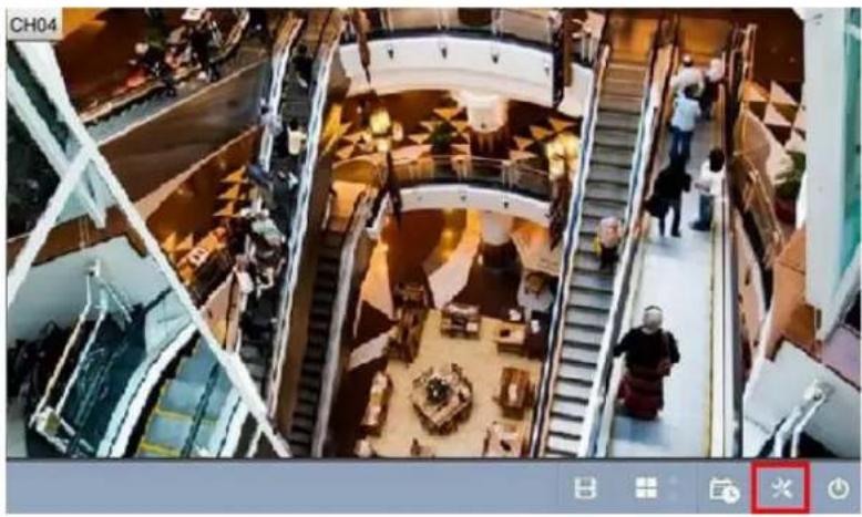
- On the main screen, click the Setting button.
natural_image
Aerial view of a multi-level shopping mall with escalators and shoppers (no visible text or signage)Figure 2-24
- Select Storage.
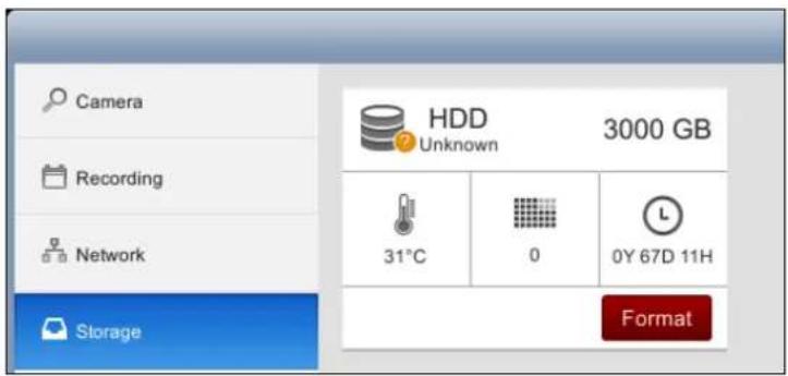
Figure 2-25
- Click Format. This dialog box appears.
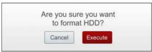
Figure 2-26
- Click Execute to format the hard drive.
When the hard drive is successfully formatted, its icon should be marked with a green tick, and the "Normal" message appears. The information of operating temperature, hard drive status and total time in use is also displayed.
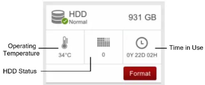
Figure 2-27
Note: When the hard drive status displays other value instead of 0, replace the hard drive with a new one to ensure proper video recording.
2.5 Main Screen
Close the Camera page to see the connected channels on the main screen. Here we use GV-SNVR0400F for illustration.
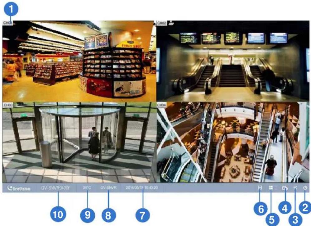
Figure 2-28
No. Name Description
| 1 | Camera Name | Indicates the camera name. The column changes from gray to red when the recording is enabled. See Camera Name in 3.1 Camera. |
| 2 | System | Brings up the options: Log Out and Shutdown. |
| 3 | Setting | Accesses the following setting pages:• Camera (see 3.1 Camera)• Recording (see 3.2 Recording)• Network (see 3.3 Network)• Storage (see Chapter 2.4 Formatting the Hard Drive)• Display (see 3.5 Display)• Service (see 3.6 Service)• System (see 3.7 System) |
| 4 | Record | Starts/Stops monitoring. |
| 5 | Division & Page Up / Down | Selects screen divisions and switch between cameras in single division. |
| 6 | Playback | Displays the playback panel. |
| 7 | Date / Time | Displays the current date and time. |
| 8 | Device Name | Displays the device name of GV-SNVR. See Device Name in 3.7 System. |
| 9 | Temperature | Displays the current temperature. |
| 10 | Model Name | Displays the model name of GV-SNVR. |
2.6 Enabling Recording
To start recording, click the Record button (No. 4, Figure 2-28) and select a camera. To enable recording for all the connected cameras, select Start All Monitoring.
By default, the GV-SNVR records with the Round-the-clock mode. The default recording resolution and codec depend on the settings of each camera.
• To change recording mode, see 3.2 Recording.
• To change video resolution, see 3.1 Camera.
2.7 Playing Back Video
You can instantly play back the recorded video without interrupting the monitoring and recording.
- To instantly play back the recording of one single channel, click the Camera Name (No. 1, Figure 2-28), select Instant Playback.
- To instantly play back the recording of all channels, click the Playback button (No. 6, Figure 2-28).
Note: For details on playing back the recording, see Chapter 4 Video Playback.
2.8 Live Monitoring
GV-SNVR0411 / GV-SNVR0400F
On the main screen, the live view of connected cameras is displayed in 4 divisions by default. You can click the Division button (No. 5, Figure 2-28) and select 1 or 4 Division. Optionally, click on the live view of desired camera to switch to full screen.
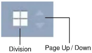
Figure 2-29
GV-SNVR1600
On the main screen, the live view of connected cameras is displayed in 16 divisions by default. You can click the Division button and select 1, 4 or 9 Division. Optionally, click on the live view of desired camera to switch to full screen.
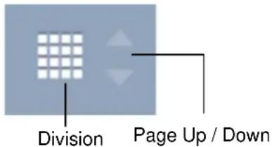
Figure 2-30
2.8.1 Snapshot
To take a snapshot of live or playback video, follow the steps below.
- Connect an USB USB flash drive of FAT32 format to the GV-SNVR.
- Click the camera name of desired camera and select Snapshot. The message "Snapshot Success" pops up when the captured image is successfully saved to the USB USB flash drive.
Each image is automatically saved in JPEG format with a file name indicating the date and time of snapshot.
2.8.2 Audio
To enable the audio function on live video, follow the steps below.
Note: To listen to the audio, make sure the Enable Audio function is applied for the camera. For details, see 3.1 Camera.
- Click the live view of the desired camera to switch to full screen.
- Click the camera name and select Speaker. The audio icon 📋 appears beside the camera name, and the audio is now accessible.
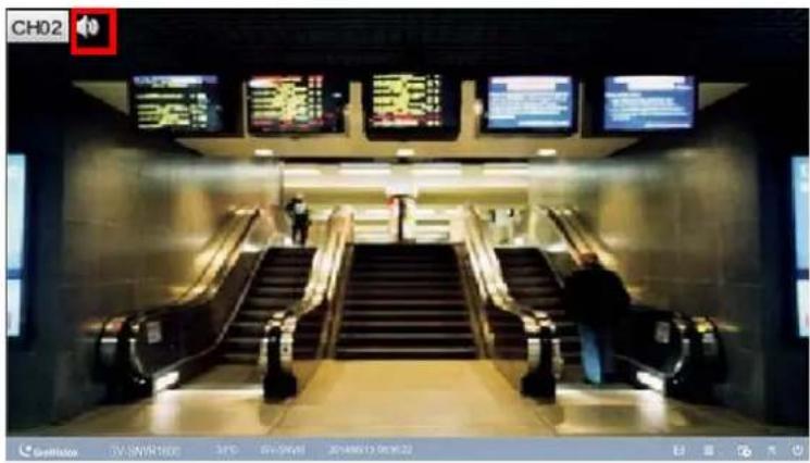
Figure 2-31
2.8.3 PTZ Control
To enable the PTZ function on live video, click the camera name of desired camera and select Enable PTZ. The PTZ control panel appears at the lower-right corner of the live view.
Note: The option is only available for the cameras supporting PTZ functions.
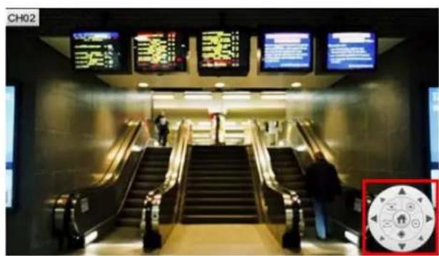
Figure 2-32
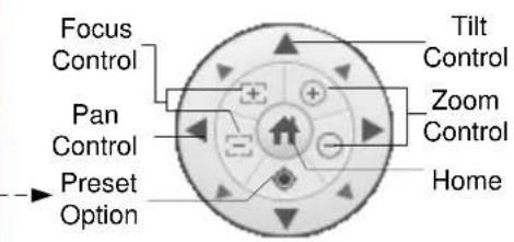
Figure 2-33
■ Home: Brings the PTZ live view back to the Home position.
■ Pan/Tilt Control: Allows the camera to pan and tilt to any angle.
■ Zoom Control: Allows the camera to zoom in or out.
■ Focus Control: Adjusts the camera to focus in or out.
■ Preset Option: Moves the camera to a preset point by entering a preset number using the onscreen keypad.
To enable PTZ control, you can also use the GV-Joystick V2, a plug-and-play device used to pan, tilt, zoom and focus a PTZ camera. When the GV-Joystick V2 is connected to the USB port on the GV-SNVR, the Joystick icon will appear beside the camera name.
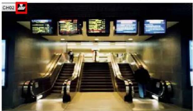
Figure 2-34
For details on the GV-Joystick V2, see GV-Joystick V2 User's Manual.
Note:
- The GV-SNVR does not support GV-Keyboard.
Digital PTZ Function
For non-PTZ cameras, the Digital PTZ (DPTZ) function allows you to simulate the PTZ movement on the screen.
Note: The DPTZ function is only available for GV-SNVR1600.
To enable the DPTZ function on live video, click the camera name of desired camera and select Enable Digital PTZ. The PTZ control panel appears at the lower-right corner of the live view.
Click the Zoom In button first and then click Tilt and Pan buttons to move the camera view.
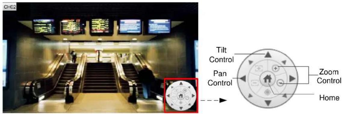
Figure 2-35
Figure 2-36
■ Home: Brings the DPTZ live view back to the Home position.
■ Pan/Tilt Control: Allows you to pan and tilt on the live view.
■ Zoom Control: Allows you to zoom in or out on the live view.
Note:
- The Focus Control and Preset functions are not supported.
- The DPTZ function is only available for non-PTZ cameras.
Chapter 3 System Configuration
This section introduces the settings of camera, video recording, network, storage, display, service and system.
3.1 Camera
To access the camera settings, click the Edit button ✗ of the camera on the Camera page.
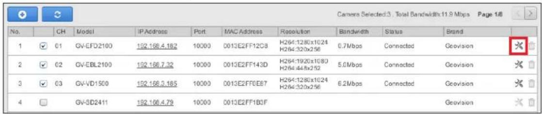
Figure 3-1
The Camera Settings page appears.
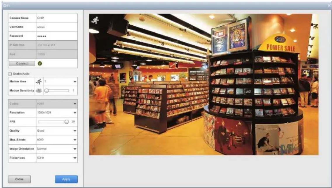
Figure 3-2
■ Camera Name: Type a desired name for the camera.
■ Username: Type the username of the camera. The default is admin.
■ Password: Type the password of the camera. The default is admin.
■ Enable Audio: Click to enable audio streaming.
■ Motion Area: Draw up to 8 areas with different sensitivity values on the image for motion detection.
■ Motion Sensitivity: Configure the sensitivity value from 1 to 10 for the motion detection. The higher the value, the more sensitive the camera is to the motion.
■ Codec: For GV-SNVR0400F / 1600, the video codec is H.264. For GV-SNVR0411, select video codec between H.264 and H.265.
■ Resolution: Select the video resolution for the camera.
■ FPS: Set up recording frame rate for the camera. Note the GV-SNVR supports up to 30 fps.
■ Quality: Select the level of video quality.
■ Max. Bit Rate: Set up the maximum bit rate of video stream.
■ Image Orientation: Adjust the image orientation by selecting Normal, Horizontal Mirror, Vertical Flip or Rotate 180.
- Flicker less: The frequency of your camera's image is automatically matched with the frequency of indoor light sources, e.g. fluorescent lighting. You can also select 50 Hz or 60 Hz manually. If the frequencies don't match, faint light and dark bars may appear in your images. Check the power utility to determine which frequency is used.
To enable the settings, click Apply.
3.2 Recording
You can set up desired recording mode for specific period on specific days for each connected camera. The default recording mode is round-the-clock.
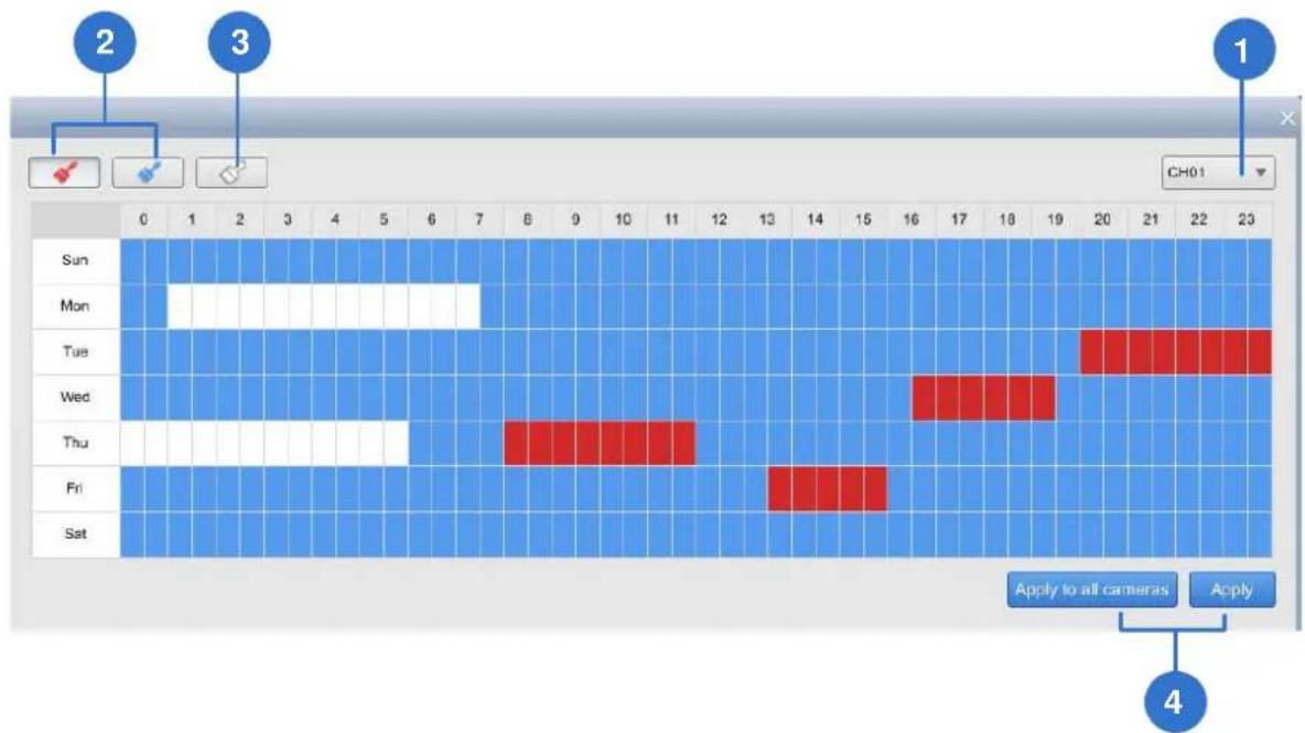
Figure 3-3
- Select a camera from the drop-down list at the upper-right corner.
- To set up the recording mode, click the Motion Recording icon or Round-the-clock icon and drag the cursor on the desired period.
- To clear the settings, click the Clear icon and drag the cursor on the desired period.
- Click Apply or Apply to all cameras as needed to enable the settings.
3.3 Network
The Network section includes basic network configurations that enable the GV-SNVR to be connected to the network. By default, the GV-SNVR is assigned with a dynamic IP address when connecting to the network.
[LAN]
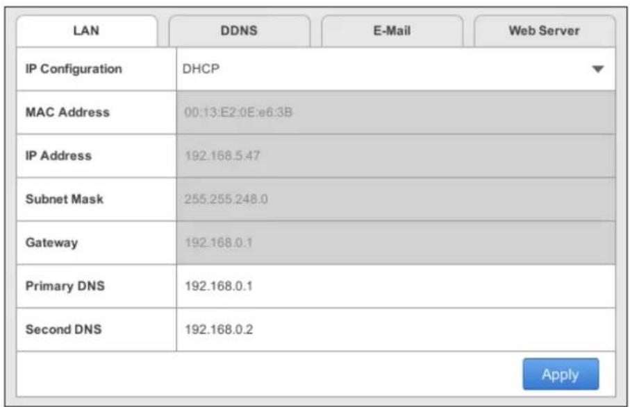
Figure 3-4
■ IP Configuration: Select DHCP or Static according to your network environment.
■ MAC Address: Displays the MAC Address of the GV-SNVR.
To assign a static IP address, select Static and fill out the required settings below.
■ IP Address: Type a static IP address for the GV-SNVR. The default is 192.168.0.100.
■ Subnet Mask: Type a subnet mask. The default is 255.255.255.0.
■ Gateway: Type a gateway. The default is 192.168.0.1.
■ Primary DNS: Type a primary DNS. The default is 192.168.0.1.
■ Second DNS: Type a second DNS. The default is 192.168.0.2.
Click Apply. The GV-SNVR is now accessible by entering the assigned IP address on Web browser.
[WAN]
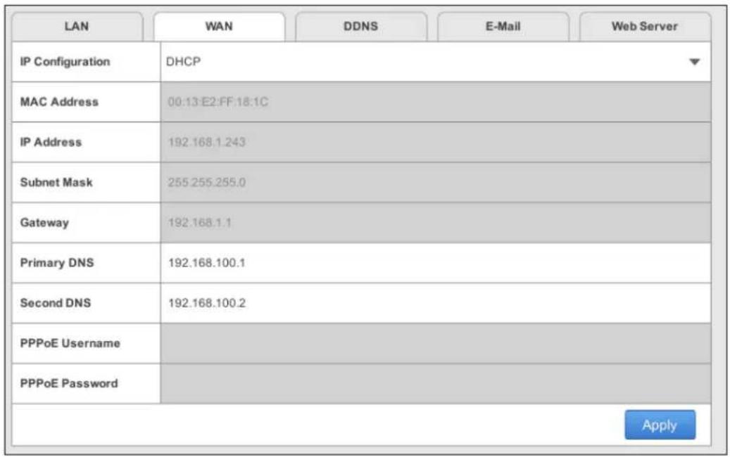
Figure 3-5
■ IP Configuration: Select DHCP or Static according to your network environment.
■ MAC Address: Displays the MAC Address of the GV-SNVR.
To enable the PPPoE connection, select PPPoE and fill out the required settings below.
■ Primary DNS: Type a primary DNS. The default is 192.168.100.1.
■ Second DNS: Type a second DNS. The default is 192.168.100.2.
■ PPPoE Username: Type the username you have registered for PPPoE.
■ PPPoE Password: Type the password you have registered for PPPoE.
Note: The WAN configuration is only available for GV-SNVR1600.
IMPORTANT: When the LAN and WAN are applied simultaneously, note the following:
- Only the WAN can be connected to the Internet.
- Only the IP Cameras under the same LAN can be searched by the GV-SNVR1600. To connect with the IP cameras under the WAN, you must add the cameras manually. For details, see 2.3.2 Manually Connecting GV-IP Camera.
[DDNS]
DDNS (Dynamic Domain Name System) provides a convenient way of accessing the GV-SNVR when using a dynamic IP address. DDNS assigns a domain name to the GV-SNVR, so you do not need to go through the trouble of checking if the IP address assigned by DHCP Server or ISP (in xDSL connection) has changed. Before enabling the following DDNS function, you should have applied for a Host Name from the DDNS service provider's website. The provider is GeoVision DDNS Server:
http://ns.gvdip.com/register.aspx.
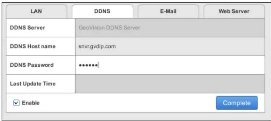
Figure 3-6
To enable the DDNS function, click the Enable box, type the hostname and password you have registered with GeoVision DDNS Server and click Apply.
[E-mail]
Configure your mail server to allow e-mail notification upon:
- Recording error of writing recording data to the hard disk drive
- Request for retrieving the username and password for system login
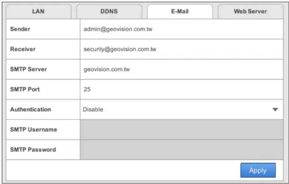
Figure 3-7
■ Sender: Type the sender's e-mail address.
■ Receiver: Type the recipients' e-mail address.
■ SMTP Sever: Type your mail server's URL address or IP address.
■ SMTP Port: Type your mail server's port value.
■ Authentication: Select Enable if the SMTP Server needs authentication and type a valid username and password to log in the SMTP server in the next two columns. Select Enable SSL if your e-mail server requires the SSL authentication for connection.
[Web Server]
| LAN | DDNS | Web Server | |
| Web Port | 80 | ||
| Streaming port (VSS) | 10000 | ||
| Apply | |||
Figure 3-8
■ Web Port: The Web Port is used for connection with compatible GeoVision software and allows users to access GV-SNVR through the Web interface. The default port is 80.
■ Streaming port (VSS): The VSS streaming port is used for connection with GV-Eye mobile application and compatible GeoVision software. The default port is 10000.
3.4 Storage
You must format the hard drive before enabling the video recording. For details, see Formatting the Hard Drive in Chapter 2.
3.5 Display
You can adjust how you want GV-SNVR to be displayed.
| Language | English |
| Show Style | Default |
| Date Format Setup | YYYY-MM-DD |
| Temperature | °C |
| Auto Scan(sec.) | 15 |
| Resolution | 1080P |
| Apply | |
GV-SNVR0400F / 1600
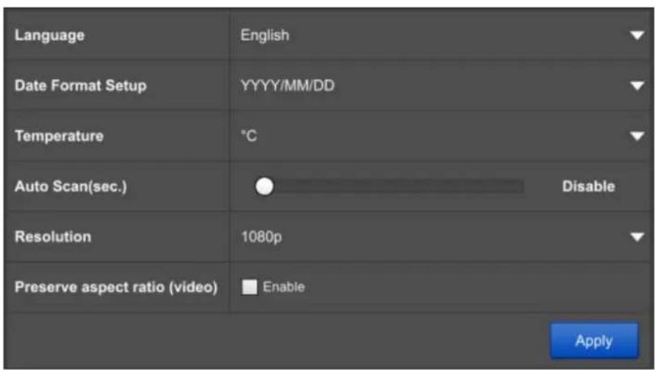
GV-SNVR0411
Figure 3-9
■ Language: Select a language for the OSD interface.
■ Show Style: Select a color scheme for GV-SNVR interface. Black scheme is selected by default. This function is only supported by GV-SNVR0400F / 1600.
■ Date Format Setup: Select a display format for the date.
■ Temperature: Select to display the operating temperature in Celsius or Fahrenheit.
■ Auto Scan (sec.): Set a scan interval in seconds to enable the Auto Scan function. If the number of cameras added exceeds the number of live view grids available, the cameras will be shown in sequence for the selected time interval. In the example of a 15-second scan interval with 16 cameras in 9-ch division, GV-SNVR will alternate between 15 seconds of cameras 1 - 9 and 15 seconds of cameras 10 - 16.
■ Resolution: Select the video output resolution.
| Model | Video Output |
| GV-SNVR0411 | 1080p, 4K |
| GV-SNVR0400F | 720p, 1080p, 1080i |
| GV-SNVR1600 | 1080p |
■ Preserve Aspect Ratio (Video): Only for GV-SNVR0411, enable to preserve the aspect ratio of your camera. Restart the GV-SNVR System for the change to take effect.
IMPORTANT: For GV-SNVR0411, when you configure the channel resolution to 4K, be sure your monitor is a 4K-capable monitor; otherwise flickering / no image will be displayed on the screen. If it occurs, load factory default, and the resolution will be set to 1080p.
3.6 Service
3.6.1 Connecting GV-SNVR with GV-Center V2 and GV-Vital Sign Monitor
In the Service page, you can connect GV-SNVR with GV-Center V2 and GV-Vital Sign Monitor.
- Click Enable to enable connection with GV-Center V2 or GV-Vital Sign Monitor.
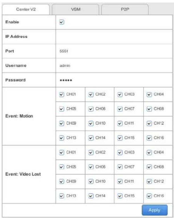
Figure 3-10
- Type the IP Address of the GV-Center V2 or GV-Vital Sign Monitor.
- Modify the Port if needed.
- Type the Username and Password of the GV-Center V2 or GV-Vital Sign Monitor.
- Only for connecting GV-SNVR0411 / 1600, select camera channels. When Motion or Video Lost Event occurs, the selected cameras will send a notification or a video to GV-Center V2 or GV-Vital Sign Monitor.
- Click Apply. A green icon will appear if the connection is established successfully.
Note:
- For compatible version of GV-Center V2 and GV-Vital Sign Monitor, see 1.4.2 Supported GeoVision Applications for details.
- For GV-Center V2, audio function of live view is only supported in Single Live View Window, and the IP device must be connected through stream 1.
- For GV-Vital Sign Monitor, the Video Log Storage function is not supported when viewing subscriber status.
3.6.2 Connecting GV-Eye to GV-SNVR
You can connect GV-Eye to GV-SNVR using the QR Code scan. Follow the steps below to scan the QR Code.
Note:
- Currently GV-SNVR1600 (firmware V1.20 or later) and GV-SNVR0411 (firmware V2.00 or later) are supported for this function.
- To use this function, the computer installed with GV-SNVR must be connected to the Internet.
-
For details, see GV-Eye Installation Guide: http://www.geovision.com.tw/english/5_4.asp
-
Click Mobile APP. This interface appears.
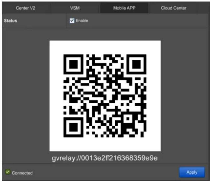
Figure 3-11
- Hold your mobile device over the QR Code on GV-SNVR to the point where the QR Code is clearly visible.
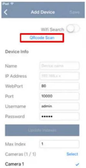
Figure 3-12
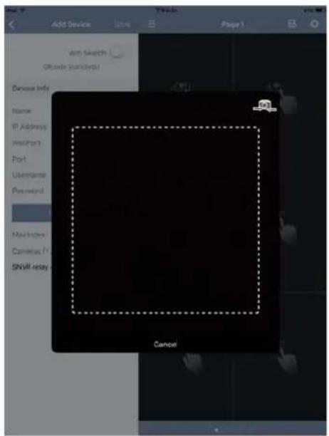
Figure 3-13
- When the scanning is successful, tap Update Indexes, and tap Save. The IP devices from GV-SNVR are imported onto the camera list of your mobile device.
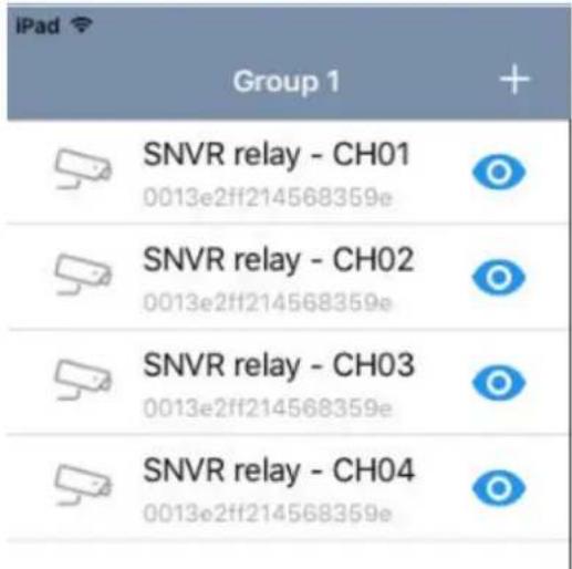
Figure 3-14
3.7 System
On the System page, you can change the device name of GV-SNVR and login information. You can also access the time settings and system log.
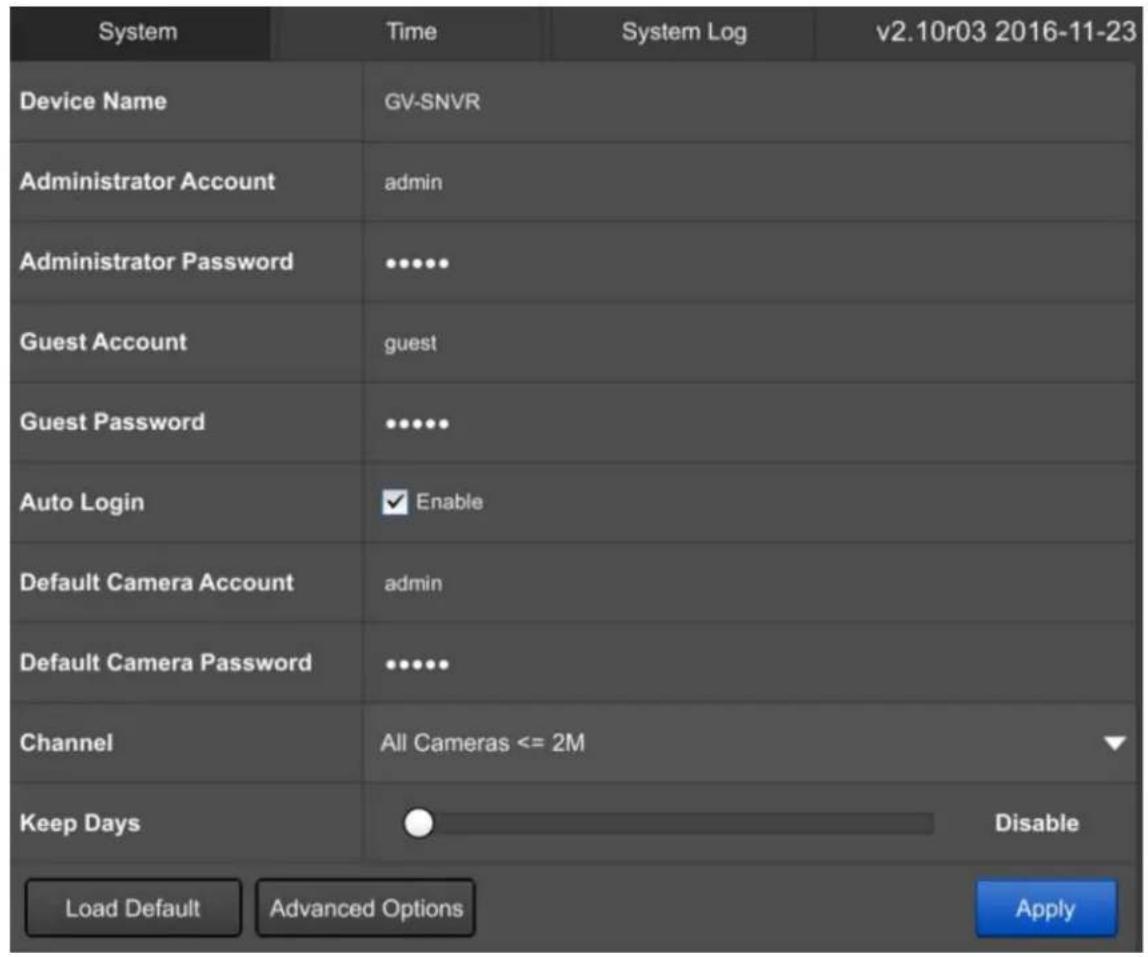
Figure 3-15
[System]
■ Device Name: Type a desired name for the GV-SNVR.
■ Administrator Account: Type the username of the Administrator. The default is admin.
■ Administrator Password: Type the password of the Administrator. The default is admin.
■ Guest Account: Type the username of the Guest. The default is guest.
■ Guest Password: Type the password of the Guest. The default is guest.
■ Auto Login: Select Enable to automatically log in the GV-SNVR at startup.
■ Default Camera Account: Set up the default username of camera for connection. The default is admin.
■ Default Camera Password: Set up the default password of camera for connection. The default is admin.
■ Channel: Only for GV-SNVR0411, select a channel mode that conforms the resolution of your camera. See the maximum resolution per channel according to the connection protocol below. For live view streaming details, see Appendix B.
For GeoVision IP Cameras
| Channel Mode | GV-SNVR0411 | |
| Channel Max. Resolution | ||
| Default | CH1CH2CH3CH4 | 8 M at 30 fps |
| One Camera >2M | CH1 8 M at 30 fps | |
| CH2*CH3*CH4* | 5 M at 12 fps4 M at 15 fps3 M at 19 fps2 M at 30 fps | |
| All Camera <=2M | CH1*CH2*CH3*CH4* | 5 M at 12 fps4 M at 15 fps3 M at 19 fps2 M at 30 fps |
| Note: If the resolution of your camera is above 5 M, the GV-SNVR compresses the video to 5 M at 12 fps (*). | ||
For Third-Party IP Cameras using ONVIF / RTSP protocol
| Channel Mode | GV-SNVR0411 | |
| Channel Max. Resolution | ||
| Default | CH1CH2CH3CH4 | 8 M at 30 fps |
| One Camera >2M | CH1 8 M at 30 fps | |
| CH2*CH3*CH4* | 2 M at 30 fps | |
| All Camera <=2M | CH1*CH2*CH3*CH4* | 2 M at 30 fps |
| Note: If the resolution of your camera is above 2 M, it is recommended to select Default Mode, or you may have problem accessing live view and playback (*). | ||
- Keep Days: Only for GV-SNVR0411 / 1600, select Enable and drag the slider to specify the number of days to keep the video files in storage.
To restore the GV-SNVR to default settings, click Load Default and follow the on-screen instructions. Optionally, press the Load Default button on the rear panel of the device for 15 seconds.
To import or export the system settings and update firmware, click Advanced Options for configuration. Optionally, you can configure through the GV-IP Device Utility. For details, see 6.2 Using the GV-IP Device Utility.
[Time]
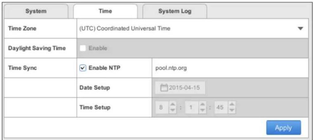
Figure 3-16
■ Time Zone: Select a time zone of your location.
■ Daylight Saving Time: Click Enable and type the start time and end time for the system to automatically adjust to Daylight Saving Time.
■ Time Sync: Click Enable NTP and type the URL of a network time server to synchronize the clock of GV-SNVR over network. Otherwise, manually set up the date and time by filling out the corresponding fields.
To enable the settings, click Apply.
Note: You can also use the GV-IP Device Utility to synchronize the date and time of GV-SNVR with a computer. For details, see GV-IP Device Utility Installation Guide on the Software CD.
[System Log]
This page lists all the changes made to the system.
| System | Time | System Log | Page 1/1 | |||
| No. | Time | Channel | Type | Event | Note | |
| 1 | 2015/04/15 02:59:47 | User | Login | Local (admin) | ||
| 2 | 2015/04/15 02:59:16 | System | Network Failure | LAN | ||
| 3 | 2015/04/15 02:59:12 | 04 | System | Recording Start | ||
| 4 | 2015/04/15 02:59:12 | 03 | System | Recording Start | ||
| 5 | 2015/04/15 02:59:12 | 02 | System | Recording Start | ||
| 6 | 2015/04/15 02:59:12 | 01 | System | Recording Start | ||
| 7 | 2015/04/15 02:59:11 | System | Network Resume | LAN | ||
| 8 | 2015/04/15 02:58:43 | System | System Startup | |||
| 9 | 2015/04/13 06:47:15 | User | Firmware Upgrade | |||
| 10 | 2015/04/13 06:47:15 | User | Log Out | Local (admin) | ||
| 11 | 2015/04/13 06:46:59 | User | HDD Format | HDD | ||
| 12 | 2015/04/13 06:46:45 | User | Login | Local (admin) | ||
| 13 | 2015/04/13 06:46:21 | System | Network Failure | LAN | ||
| 14 | 2015/04/13 06:46:18 | System | Network Resume | LAN | ||
| 15 | 2015/04/13 06:46:01 | 04 | System | Recording Start | ||
| 16 | 2015/04/13 06:46:01 | 03 | System | Recording Start | ||
| 17 | 2015/04/13 06:46:01 | 02 | System | Recording Start | ||
| 18 | 2015/04/13 06:46:01 | 01 | System | Recording Start | ||
| 19 | 2015/04/13 06:45:55 | System | System Startup | |||
Figure 3-17
To export the system log, click the Export button 📄 at the upper-right corner and click Apply. A USB flash drive needs to be inserted in order to export system log.
To search for specific events, click the Filter button at the upper-right corner to limit the search results using the following options.
■ Time: Set up the desired time period.
■ Device: Select a channel.
■ Type: Select User or System.
■ Event: Select a type of event.
Chapter 4 Video Playback
The timeline player plays back recorded video without affecting recording. There are two ways to launch the timeline player:
- On the main screen, click the Playback button (No. 6, Figure 2-28).
- On the camera live view, click the desired camera name and select Instant Playback.
On the timeline player screen, the system automatically plays back video recording from 3 minutes before the playback function is enabled.
4.1 Timeline Player
Without further settings, you can play back the video recording by selecting a time and clicking the Play button on Playback Panel. To switch the current view mode, click the Division button. Here we use GV-SNVR1600 for illustration.
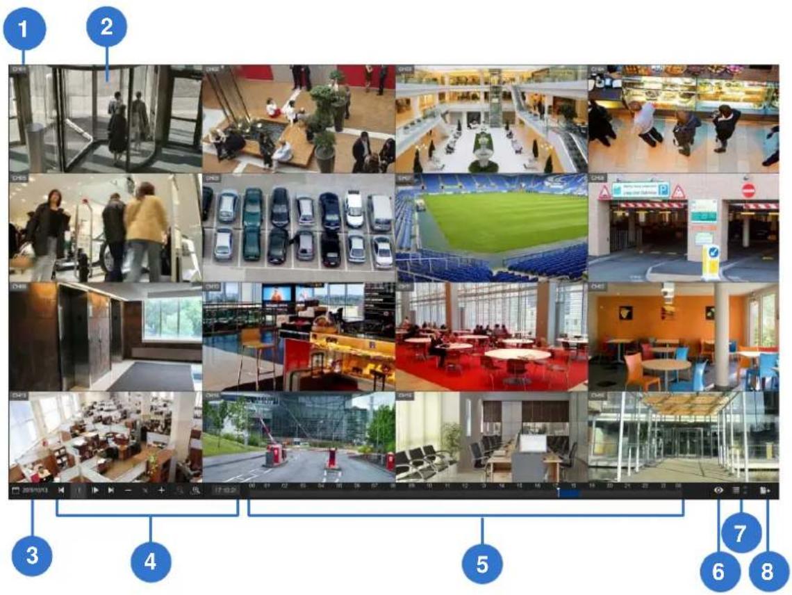
Figure 4-1
Use controls on Playback Panel to view the event in the way you want. Move the Slider forward or backward to navigate video frames.
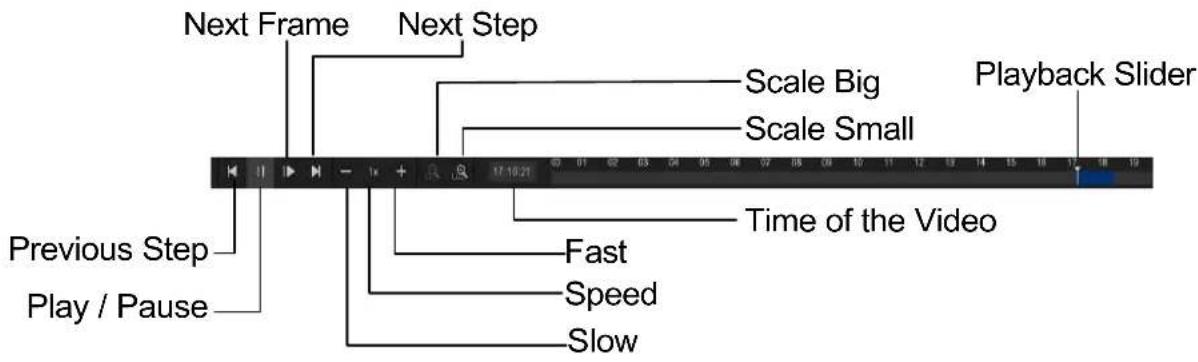
Figure 4-2
The controls in the timeline player screen:
| No. | Name | Description |
| 1 | Camera Name | Indicates the camera name. |
| 2 | Camera View | Displays the playback video. |
| 3 | Date Display | Allows you to specify a date to play back the recorded video. The date with video recording is highlighted in blue. |
| 4 | Playback Panel | Contains typical playback control buttons. |
| 5 | Timeline | The time with video recording is highlighted in blue.For GV-SNVR0411 / 1600,a) With theScale Smallbutton  clicked, displays a 24-hour timeline consisting of 24 grids with each specifying an hour.b) With theScale Bigbutton [c2xw] clicked, displays a 60-minute timeline consisting of 12 grids with each specifying five minutes.For GV-SNVR0400F, displays a 24-hour timeline consisting of 48 grids, with each specifying half an hour. clicked, displays a 24-hour timeline consisting of 24 grids with each specifying an hour.b) With theScale Bigbutton [c2xw] clicked, displays a 60-minute timeline consisting of 12 grids with each specifying five minutes.For GV-SNVR0400F, displays a 24-hour timeline consisting of 48 grids, with each specifying half an hour. |
| 6 | Live | Closes the timeline player and returns to live view window. |
| 7 | Division | For GV-SNVR0411 / 0400F, switches between 1-channel and 4-channel view; for GV-SNVR1600, switches between 1-channel, 4-channel, 9-channel and 16-channel view. |
| 8 | Export | Exports the video recording as AVI files to a USB flash drive. |
4.2 Recording Backup
Using the timeline player, you can back up recordings to the USB flash drive. To back up recordings, follow the steps below.
- Connect a USB flash drive of FAT32 format to the USB port on the unit.
- On the timeline player screen, click Export (No.8, Figure 4-1).
For GV-SNVR0411
- Select GeoVision AVI to export video without audio.
- Select Standard AVI to export video with audio. Note the Standard AVI file is not supported by GeoVison applications.
For GV-SNVR0400F / 1600, the backup recordings are in GeoVision AVI format.
- Select the desired date and time period of video recording.
- Select the channel of desired camera and click Export.
For backup recordings in GeoVision AVI or Standard AVI format, you need to install GeoVision codec in the dedicated PC to play back the recordings using Windows Media Player. For GeoVision AVI format only, you can install the GV-ViewLog player for playback.
Note:
- For GV-SNVR0400F / 1600, the recording backup only supports video. The audio will not be included in the backup recordings.
- If the GV-SNVR is connected with more than one USB flash drive, the video recordings will be backed up to the first USB flash drive connected.
Chapter 5 Remote Access to the GV-SNVR
Users can remotely access the GV-SNVR through the following methods:
- Web browser
● Mobile devices installed with GV-Eye
● GV-Edge Recording Manager
GV-Control Center
Note:
- For supported Web browsers and compatible GeoVision applications, see 1.4 Compatible Products and System Requirements for details.
- The maximum number of remote network connection is 10 in total for GV-SNVR0411 / 0400F and 34 in total for GV-SNVR1600. Every connected channel will be counted as 1 connection.
- GV-Edge Recording Manager / GV-Control Center can remotely play back recordings stored on GV-SNVR. However, GV-SNVR only supports remote playback from 2 GV-Edge Recording Manager / GV-Control Center at the same time.
5.1 Accessing through Web browser
To access the live view through Web interface, follow the steps below. Here we use the GV-SNVR0400F for illustration.
- Open your Web browser and type the IP address of the GV-SNVR.
Note: To look up the IP address of GV-SNVR, see 3.3 Network. Optionally, run the GV-IP Device Utility to search for your GV-SNVR. For details, see 6.2 Using the GV-IP Device Utility.
- In both Username and Password fields, type the default value admin.
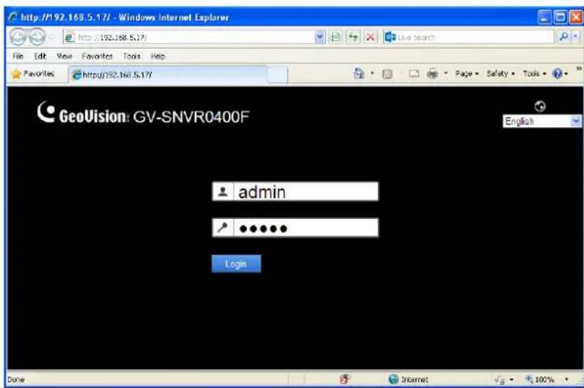
Figure 5-1
-
Select a desired language from the drop-down list at the upper-right corner for the Web interface and click Login.
-
To enable the update of live view on your Web browser, you must set the Web browser to allow ActiveX controls and perform a one-time installation of GeoVision's ActiveX components on your computer.
After the installation, live view will be displayed.
5.1.1 Live View Screen
After successfully logging in the Web interface, you can access the live view of connected IP cameras.
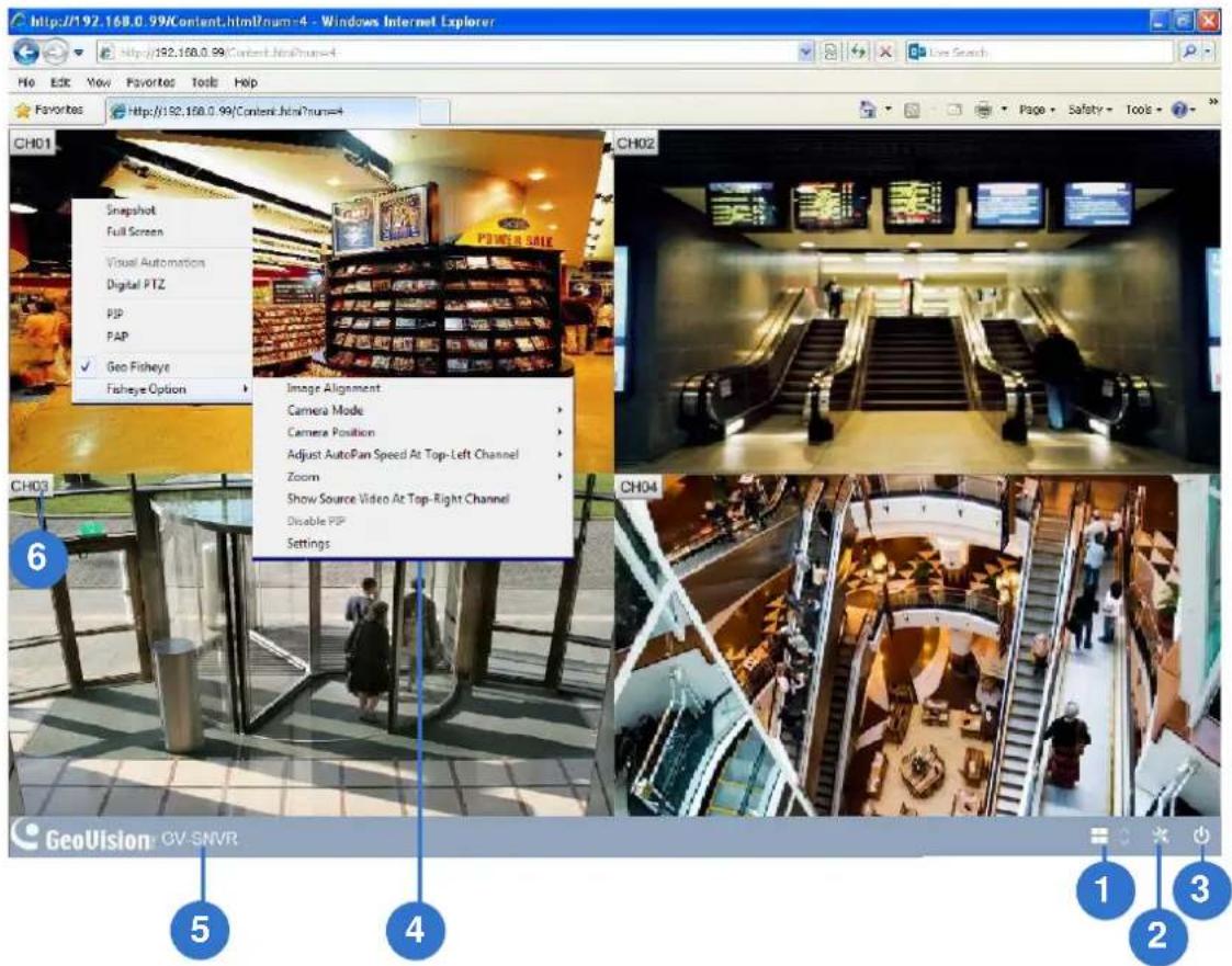
Figure 5-2
| No. | Name Description | |
| 1 | Division & Page Up / Down | Select screen divisions and switch between cameras in single division. |
| 2 | Setting | Access the following system configuration pages of GV-SNVR: Camera (only for GV-SNVR0411), Recording, Network, Storage, Service, System.See Chapter 3 System Configuration for more information on these settings. Note that the System Log is not accessible in the System page of the Web interface. |
No. Name Description
| 3 Exit | Log out the Web interface. | |
| 4 | Advanced Options | Right-click the live view of desired camera to access the functions below.Snapshot: Take a snapshot of live video. For details, see 5.1.2 Snapshot of Live Video.Full Screen: Switch the live view to full screen.Resolution: Display the resolution at the lower-right corner of the live view.Digital PTZ: Simulate the PTZ movement on the screen. For details, See 5.1.5 Digital PTZ Control.PIP: Enable the PIP function. For details, See 5.1.3 Picture-in-Picture View.PAP: Enable the PAP function. For details, See 5.1.4 Picture-and-Picture View.Geo Fisheye: Only for GV-SNVR0411, select to open the fisheye settings. For details, See 5.1.6 Fisheye View. |
| 5 | Device Name | Shows the device name of GV-SNVR. See Device Name in 3.7 System. |
| 6 | Camera Name | Click the camera name to capture snapshot or enable the speaker. |
Note:
- The Web interface of GV-SNVR only connects to the main stream of GV-IP Cameras when using single division and 4-division display. For details, see Appendix B Live View Streaming.
- The Visual Automation function is not supported.
- The audio function is only supported on the live view of Web interface when the screen division is set to single division or 4 divisions.
5.1.2 Snapshot of Live Video
To take a snapshot of live video, follow the steps below.
- Right-click on the live view of desired camera and select Snapshot. This dialog box appears.
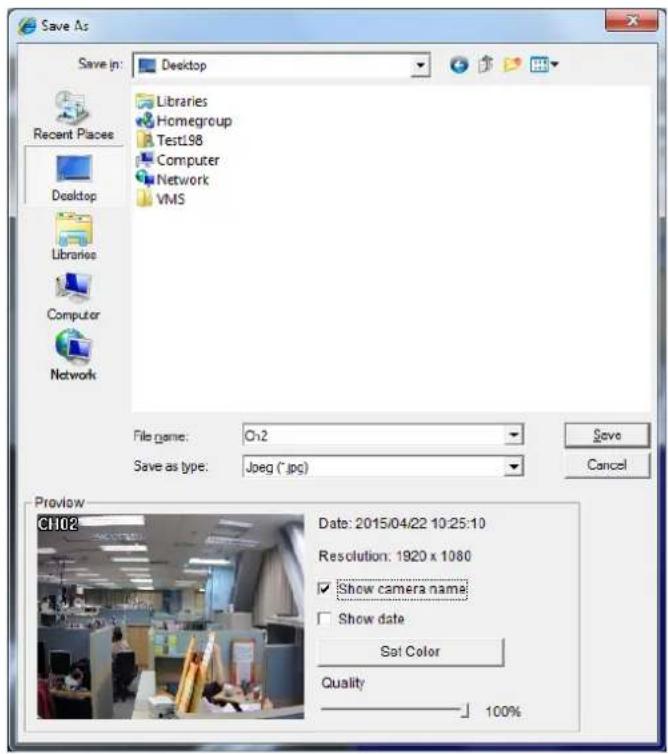
Figure 5-3
- Select a desired saving path, type the file name and select JPEG or BMP as the Save as Type.
- In the Preview field, you can choose whether to tag the snapshot with camera name, time and date, select Set Color for the text color and adjust the image quality.
- Click Save to save the captured image.
5.1.3 Picture-in-Picture View
With the Picture in Picture (PIP) view, you can crop the video to get a close-up view or zoom in on the video. This function is useful for detailed images of the surveillance area.
- Right-click the desired camera live view and select PIP. An inset window of the camera view appears in the bottom right corner.
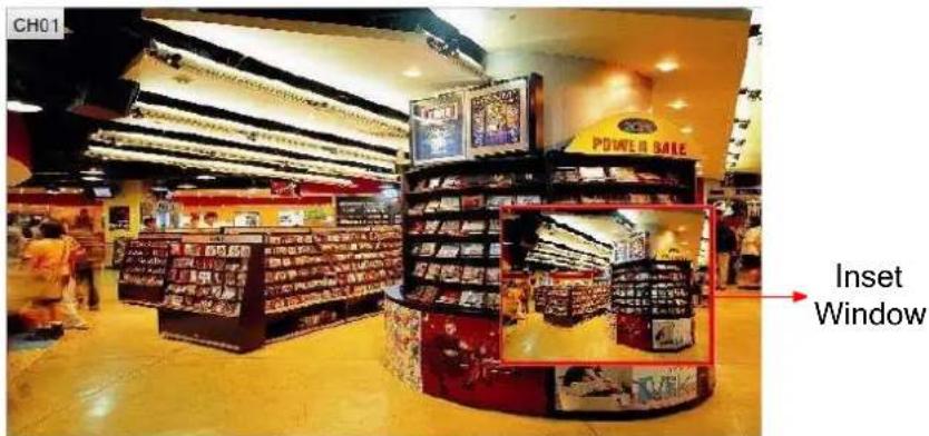
Figure 5-4
- Double-click the inset window. A hand icon appears.
- Click the inset window. A navigation box appears.
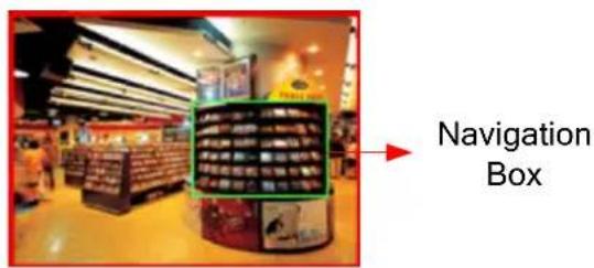
Figure 5-5
- Move the navigation box around in the inset window to have a close-up view of the selected area.
- To adjust the navigation box size, move the cursor to any of the box corners to enlarge or diminish the box.
- To change the frame color of the navigation box, right-click the image, select Mega Pixel Setting and then Set Color of Focus Area.
- To exit the PIP view, right-click the camera view and click PIP again.
5.1.4 Picture-and-Picture View
With the Picture and Picture (PAP) view, you can create a split video effect with multiple close-up views on the image. Up to 7 close-up views can be defined for clear and detailed images of the surveillance area.
- Click the live view of desired camera and select PAP. A row of three inset windows appears on the bottom of the screen.
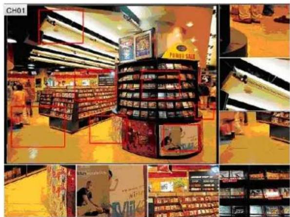
Figure 5-6
- Draw a navigation box on the image. This selected area is immediately reflected in one inset window. Up to seven navigation boxes can be drawn on the image.
- To adjust a navigation box size, move the cursor to any of the box corners to enlarge or diminish the box.
- To move a navigation box to another area on the image, drag it to that area.
- To change the frame color of the navigation box, right-click the image, select Mega Pixel Setting and click Set Color of Focus Area.
- To hide the navigation box on the image, right-click the image, select Mega Pixel Setting and click Display Focus Area of PAP Mode.
- To delete a navigation box, right-click the desired box, select Focus Area of PAP Mode and select Delete.
- To exit the PAP view, right-click the camera view and select PAP again.
- To add another navigation box when less than seven navigation boxes are drawn, right-click the camera view, select PAP to enter, right-click the image, select Mega Pixel Setting and then Enable Add-Focus-Area-Mode.
5.1.5 Digital PTZ Control
In non-PTZ cameras, the Digital PTZ (DPTZ) function allows you to simulate the PTZ movement on the screen. This function is also supported in PT / PTZ cameras.
Note: The Digital PTZ function is not supported in the 16-division display.
- Right-click the live view and select Digital PTZ. In the middle of the camera view, the DPTZ control panel appears.
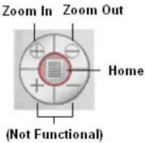
Figure 5-7
- To zoom in or zoom out, click the corresponding buttons or use the mouse scroll. To bring the visual PTZ view back to its default image, click Home.
- To pan and tilt the visual PTZ view, zoom in on the image first, and then click and hold the arrow. The arrow appears when you place the cursor in one of the eight directions, i.e. up, down, left, right, left up, left down, right up and right down.
- To adjust the transparency level of the DPTZ control panel, right-click the camera view, find Digital PTZ and select Transparency. Ten levels range from 10% (fully transparent) to 100% (fully opaque).
- To close the DPTZ control panel, right-click the camera view and select Exit.
5.1.6 Fisheye View
Only for GV-SNVR0411 connecting GeoVision IP Fisheye camera, a fisheye camera allows you to cover all angles of a location with just one fisheye camera. Using different fisheye view modes, the distorted hemispherical image produced by the fisheye camera can be converted to a conventional rectilinear projection.
To enable the fisheye options, right-click the live view and select Geo Fisheye. Right-click the image again and select Fisheye Option to see the following options.
■ Image Alignment: By default, the image should be properly aligned already. If not, follow the steps below to align the image for each model:
- GV-FE3402 / 3403 / 5302 / 5303 and GV-FER3402 / 3403 / 5302 / 5303 / 5700 / 12203: Align the red circle with the outer edge of the camera image, and then align it with the inner edge of the image frame to achieve optimal results.
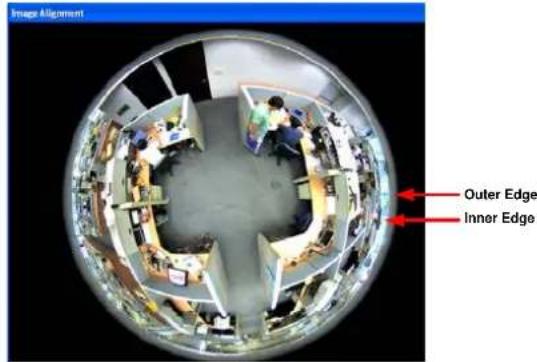
Figure 5-8
- GV-FE2301 / 4301: Align the red circle with the edge of the camera image. You can eliminate the darker areas toward the edge of the image by making the red circle smaller, but the field of view will be slightly reduced.
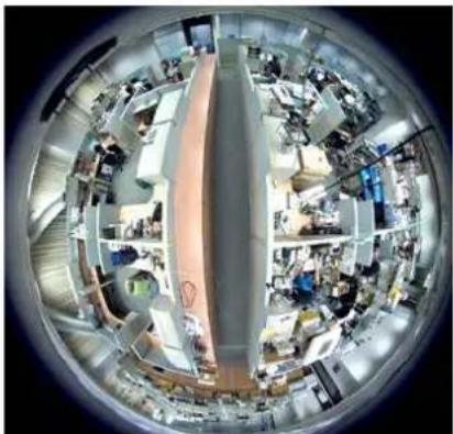
natural_image
Panoramic fisheye view of a modern office or laboratory space with workstations and equipment (no visible text or symbols)Figure 5-9 When GV-FE2301 / 4301 images are aligned, all four edges will be cropped slightly.
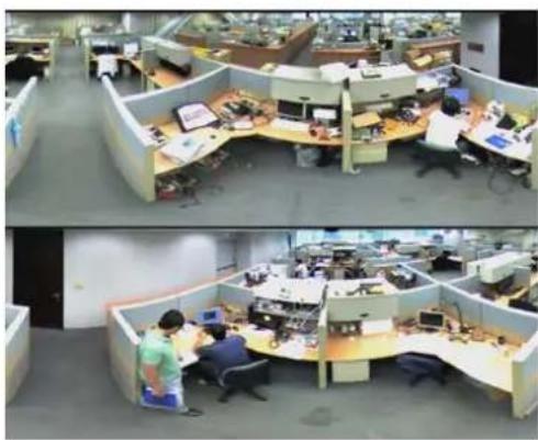
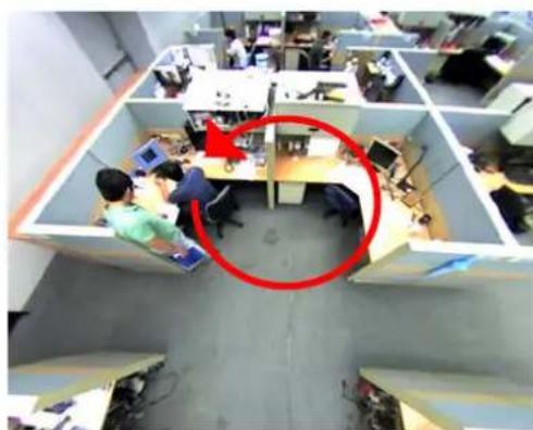
■ Camera Modes: You can choose among four view modes.
• Quad view: Composed of four PTZ views.
- 360 degree: Composed of two PTZ view and one 360^ panoramic view.
- Dual 180 degree: Composed of two 180^ views.
- Single view: Composed of one PTZ view.
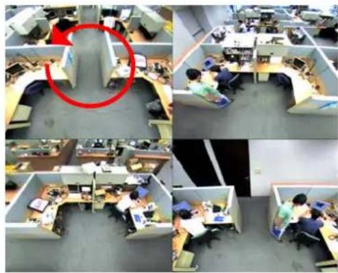
natural_image
Four-panel aerial view of an open-plan office with employees at desks and a red circle highlighting a specific workspace (no visible text or symbols)Quad view: 4 PTZ views
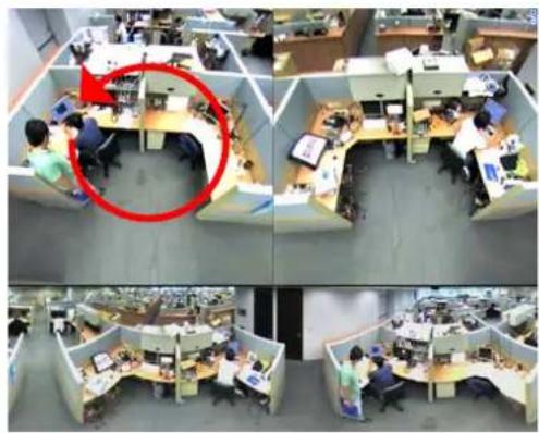
natural_image
Four-panel photo collage of an open-plan office with employees at desks, one highlighted by a red circle (no visible text or symbols)360 degree: 2 PTZ views &1 360° view
natural_image
Interior view of a busy open-plan office with cubicles and workstations (no visible text or signage)Dual 180 degree: 2 180° views
natural_image
Overhead view of an open-plan office with employees at cubicles and a red circle highlighting a specific workspace (no visible text or symbols)Single view: 1 PTZ view
Figure 5-10
Note: When wall mount is selected for Camera Position, only one 180° view will be displayed.
■ Camera Position: Select Ceiling, Wall or Ground according to where the camera is mounted.
■ Adjust AutoPan Speed At Top-Left Channel: Select low, medium, or high speed to enable Auto Pan for one PTZ view at the rotation speed of your choice. This option applies to Quad view, 360° degree and Single view.
■ Zoom: Select Zoom In or Zoom Out and then click on the image.
■ Show Source Video at Top-Right Channel: Shows the circular source image in the top-right quadrant when Quad view is selected.
■ Settings: The following settings are available.
- Wide View: Increase the height of the 180 degree view when camera position is set to wall mount.
- Frame Rate Control: You can set the frame rate of the live view image.
5.2 Accessing through Mobile Device
To access the live view of GV-SNVR through the iOS or Android devices, you must install GV-Eye on your mobile devices. With GV-Eye, you can watch multiple live view in dual streams, enable the Picture in Picture (PIP) function and take snapshots from your mobile device. To download the latest GV-Eye and its installation Guide, visit http://www.geovision.com.tw/english/5_8_App.asp
Note: Audio function is only supported when the IP device is connected through stream 1.
5.3 Accessing through GV-Edge Recording Manager
You can connect to GV-SNVR from GV-Edge Recording Manager to access live view and play back recordings. For details, refer to GV-Edge Recording Manager User's Manual.
Note:
- GV-SNVR0400F / 1600 is only compatible with GV-Edge Recording Manager (Windows Version) V1.1.0.0 or later; GV-SNVR0411 is only compatible with GV-Edge Recording Manager (Windows Version) V1.2.0.0 or later.
- Audio function of live view is only supported in Single Live View Window, and the IP device must be connected through stream 1.
5.4 Accessing through GV-Control Center
You can connect to GV-SNVR from GV-Control Center to access live view and play back recordings. For details, refer to GV-Control Center User's Manual.
Note:
- GV-SNVR0400F / 1600 is only compatible with GV-Control Center V3.3.0.0 or later; GV-SNVR0411 is only compatible with GV-Control Center V3.4.0.0 or later.
- Audio function of live view is only supported in Single Live View Window and Matrix View, and the IP device must be connected through stream 1.
Chapter 6 Advanced Applications
6.1 Upgrading System Firmware
GeoVision periodically release the updated firmware on the Website. You can upgrade the firmware using a USB flash drive of FAT32 format.
To upgrade the firmware, follow the steps below.
- Download the firmware file to a USB flash drive.
- Connect the USB drive to the GV-SNVR.
- On the main screen, click the Setting button ✕ and select System.
- Click the Advanced Option button and select Firmware Upgrade.
- Find the firmware file and click Apply. This dialog box appears.
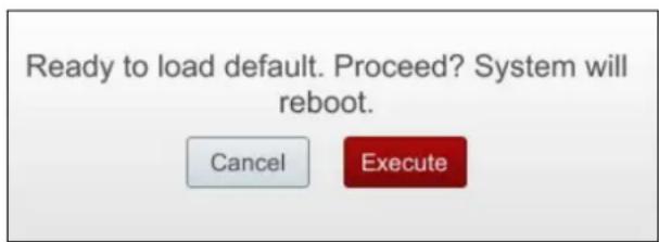
Figure 6-1
- Click Execute. The system starts upgrading firmware and automatically reboots after completing the process.
After the system reboot, the main screen will be displayed automatically.
Note: Optionally you can use the GV-IP Device Utility to upgrade system firmware, especially for multiple GV-SNVR. For details, see the Upgrading System Firmware section in 6.2 Using the GV-IP Device Utility.
6.2 Using the GV-IP Device Utility
The GV-IP Device Utility detects all the GV-IP Devices in the LAN and allows you to quickly set up the IP address of the device, upgrade firmware and export/import device settings. For details, see GV-IP Device Utility Installation Guide on the Software CD/DVD.
6.2.1 Looking up the IP Address
You can use the GV-IP Device Utility to look up the IP address of your GV-SNVR and GV-IP Camera.
- Install the GV-IP Device Utility from the Software CD / DVD.
- Double-click the GV-IP Device Utility icon created on your desktop. This dialog box appears and IP devices under the LAN are automatically detected.
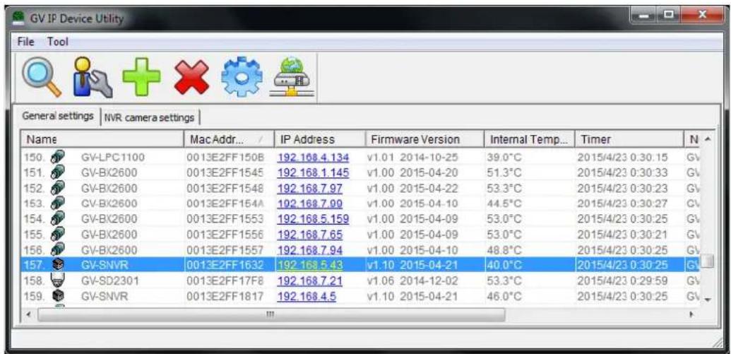
Figure 6-2
- Double-click the IP device and select Web Page to access its Web interface.
6.2.2 Accessing the Live View
You can use the GV-IP Device Utility for quick access to the live view of IP cameras connected with SNVR.
- Double-click the GV-SNVR in the list and select Live View.
- Select a camera and type the username and password of the camera to access the live view.
6.2.3 Upgrading System Firmware
You can also use the GV-IP Device Utility to upgrade firmware of multiple GV-SNVR at the same time. Note the computer used to upgrade firmware must be under the same LAN with the GV-SNVR.
- Double-click the GV-SNVR in the list and select Configure. This dialog box appears.
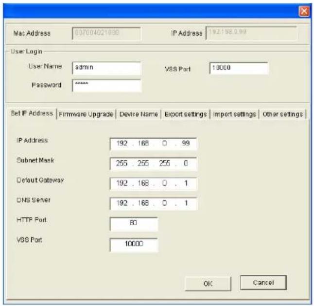
Figure 6-3
- Click the Firmware Upgrade tab. This page appears.
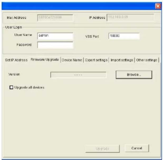
Figure 6-4
-
Click the Browse button to locate the firmware file (.img) saved at your local computer.
-
If you like to upgrade all the GV-SNVR in the list, select Upgrade all devices.
- Type Password, and click Upgrade to start the upgrade.
6.2.4 Backing up and Restoring Settings
With the GV-IP Device Utility, you can back up the configurations in the GV-SNVR and restore the backup data to the current GV-SNVR or import it to another one.
To back up the settings:
- Run GV-IP Device Utility and locate the desired GV-SNVR.
- Double-click the GV-SNVR in the list and select Configure. Figure 6-3 appears.
- Click the Export Settings tab. This dialog box appears.
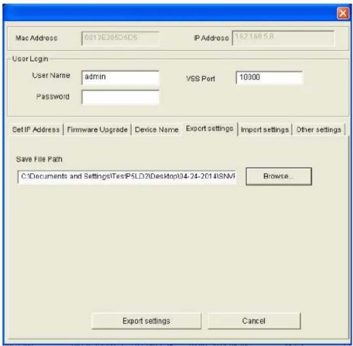
Figure 6-5
- Click the Browse button to assign a file path.
- Type Password, and click the Export Settings button to save the backup file.
To restore the settings:
- In Figure 6-5, click the Import Settings tab. This dialog box appears.
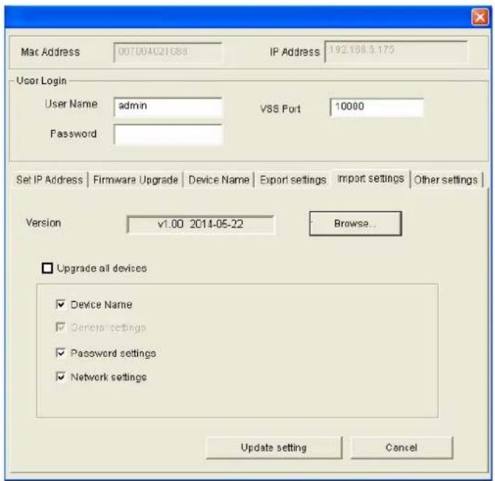
Figure 6-6
- Click the Browse button to locate the backup file (.dat).
- Select Upgrade all devices to import the settings into all the GV-SNVR under the same LAN. To import password settings and/or network settings, select Password Settings and/or Network settings.
- Click the Update Settings button to start restoring.
Appendix
A. Tested and Supported Hard Disk Drives
For system efficiency, it is recommended to use the enterprise-level hard disk drives instead of desktop-level or green HDD. The HDD listed below are tested by GeoVision.
| Model Capacity | |
| WD | |
| WD4000F9YZ 4 TB | |
| WD4000FYYZ 4 TB | |
| WD4001FAEX 4 TB | |
| WD40EFRX 4 TB | |
| WD3000F9YZ 3 TB | |
| WD3000FYYZ 3 TB | |
| WD30EFRX 3 TB | |
| WD30EURS 3 TB | |
| WD30EURX 3 TB | |
| WD2000F9YZ 2 TB | |
| WD2000FYYZ 2 TB | |
| WD20EURS 2 TB | |
| WD20EZRX 2 TB | |
| WD1003FBYZ 1 TB | |
| WD10EURX 1 TB | |
| Seagate | |
| ST8000VX0002 8 TB | |
| ST4000NC000 | 4 TB |
| ST4000NM0033 | 4 TB |
| ST3000NM0033 | 3 TB |
| ST3000VX000 3 TB | |
| ST2000NC000 2 TB | |
| ST2000VX000 2 TB | |
| ST1000DM003 | 1 TB |
| ST1000VX000 1 TB | |
| Toshiba | |
| MG03ACA400 4 TB | |
| DT01ABA300V 3 TB | |
| MG03ACA300 3 TB | |
| DT01ABA200V 2 TB | |
| DT01ACA200 2 TB | |
| Hitachi | |
| HUA723030ALA640 3 TB | |
| HUS724040ALA640 4 TB | |
| HUS724020ALA640 2 TB | |
B. Live View Streaming
The default streaming for local display and Web browser access are listed below.
| Screen Display | GV-SNVR0411 | ||
| Default | One Camera >2M | All Camera <=2M | |
| 1 Division | Stream 1 Stream 1 | Stream 1 | |
| 4 Divisions | Stream 2 | Channel 1: Stream 2Other channels: Stream 1 | Stream 1 |
| Screen Display | GV-SNVR0400F | ||
| 1 Division | Stream 1 | ||
| 4 Divisions | Stream 1 | ||
| Screen Display | GV-SNVR1600 | ||
| 1 Division | Stream 1 | ||
| 4 Divisions | Stream 1 | ||
| 9 Divisions | Stream 2 | ||
| 16 Divisions | Stream 2 | ||
C. Supported Resolution by GV-SNVR
To see the live view, make sure the resolutions of stream 1 and 2 both meet the specifications listed below.
| Camera Resolution | GV-SNVR0411 | ||
| Firmware Version | V2.10 | ||
| Stream | Main Stream | Sub Stream | |
| 4:3 | 2592 x 1944 | 1024 x 768, 960 x 720, 640 x 480, 320 x 240 | |
| 2560 x 2048 | |||
| 2560 x 1920 | |||
| 2048 x 1536 | |||
| 2048 x 1520 | |||
| 1600 x 1200 | |||
| 1280 x 960 | |||
| 640 x 480 | 640 x 480, 320 x 240 | ||
| 320 x 240 | 320 x 240 | ||
| 16 : 9 (Default) | 3840 x 2160 | 1280 x 720, 640 x 360, 448 x 252 | |
| 2592 x 1520 | |||
| 2560 x 1440 | |||
| 2304 x 1296 | |||
| 1920 x 1080 | |||
| 1280 x 720 | |||
| 640 x 360 | 640 x 360, 448 x 252 | ||
| 448 x 252 | 448 x 252 | ||
| 5:4 | 1280 x 1024 | 1280 x 1024, 640 x 512, 320 x 256 | |
| 640 x 512 | 640 x 512, 320 x 256 | ||
| 320 x 256 | 320 x 256 | ||
| 20 : 19(Fisheye Camera Only) | 2176 x 2048 | 640 x 608 | |
| 2048 x 1944 | |||
| 1792 x 1696 | |||
| 1440 x 1376 | |||
| 1280 x 1200 | |||
| Camera Resolution | GV-SNVR0400F | ||
| Firmware Version | V1.11 | ||
| Stream | Main Stream | Sub Stream | |
| 4:3 | CH1 | 1600 x 1200 | 640 x 480, 320 x 240 |
| 1280 x 960 | |||
| 640 x 480 | |||
| 320 x 240 | |||
| CH2 ~ CH4 | 1600 x 1200 | 320 x 240 | |
| 1280 x 960 | |||
| 640 x 480 | |||
| 320 x 240 | |||
| 16:9 (Default) CH1 | 1920 x 1080 | 640 x 360, 448 x 252 | |
| 1280 x 720 | |||
| 640 x 360 | |||
| 448 x 252 | |||
| Camera Resolution | GV-SNVR0400F | ||
| Firmware Version | V1.11 | ||
| Stream | Main Stream | Sub Stream | |
| 16:9 (Default) | CH2 ~ CH4 | 1920 x 1080 | 448 x 252 |
| 1280 x 720 | |||
| 640 x 360 | |||
| 448 x 252 | |||
| 5:4 | CH1 | 1280 x 1024 | 640 x 512, 320 x 256 |
| 640 x 512 | |||
| 320 x 256 | |||
| CH2 ~ CH4 | 1280 x 1024 | 320 x 256 | |
| 640 x 512 | |||
| 320 x 256 | |||
| Camera Resolution | GV-SNVR1600 | ||
| Firmware Version | V1.21 | ||
| Stream | Main Stream | Sub Stream | |
| 4:3 | CH1 | 2592 x 1944 | 640 x 480, 320 x 240 |
| 2560 x 1920 | |||
| 2048 x 1536 | |||
| 2048 x 1520 | |||
| 1600 x 1200 | |||
| 1280 x 960 | |||
| 640 x 480 | |||
| 320 x 240 | 320 x 240 | ||
| CH2~CH16 | 1600 x 1200 | 640 x 480, 320 x 240 | |
| 1280 x 960 | |||
| 640 x 480 | |||
| 320 x 240 | 320 x 240 | ||
| 16:9 (Default) | CH1 | 2592 x 1520 | 640 x 360, 448 x 252 |
| 2560 x 1440 | |||
| 2304 x 1296 | |||
| 1920 x 1080 | |||
| 1280 x 720 | |||
| 640 x 360 | |||
| 448 x 252 | 448 x 252 | ||
| CH2~CH16 | 1920 x 1080 | 640 x 360, 448 x 252 | |
| 1280 x 720 | |||
| 640 x 360 | |||
| 448 x 252 448 x 252 | |||
| 5:4 CH1~CH16 | 1280 x 1024 | 640 x 512, 320 x 256 | |
| 640 x 512 | |||
| 320 x 256 | 320 x 256 | ||
| 20 : 19(Fisheye Camera Only) | CH1 | 2048 x 1944 | 640 x 608 |
| 1792 x 1696 | |||
| 1440 x 1376 | |||
| 1280 x 1200 | |||
- GeoVision Inc
- © 2016 GeoVision, Inc. All rights reserved.
- Preface
- Caution
- Contents
- Chapter 1 Introduction.... 1
- Chapter 2 Getting Started.... 16
- Chapter 3 System Configuration 41
- Chapter 4 Video Playback 59
- Chapter 5 Remote Access to the GV-SNVR 62
- Chapter 6 Advanced Applications....75
- Appendix....80
- Chapter 1 Introduction
- Features
- Models
- Packing List and Package
- GV-SNVR Single Package
- GV-SNVR Bundled Package
- GV-SNVR0400F
- Compatible Products and System Requirements
- Supported GV-IP Cameras
- Supported GeoVision Applications
- For GV-SNVR0411
- For GV-SNVR0400F / 1600
- System Requirements
- Recommended Hard Disks
- Supported Web Browsers
- Options
- Overview
- Front View
- GV-SNVR0411
- GV-SNVR0400F
- GV-SNVR1600
- Rear View
- GV-SNVR0411
- GV-SNVR0400F
- GV-SNVR1600
- Chapter 2 Getting Started
- Installation
- GV-SNVR0411
- Installing the Hard Drive
- GV-SNVR0400F
- GV-SNVR1600
- Installing the L-Shaped Brackets
- Connecting the GV-SNVR
- Note:
- Network Connection for GV-SNVR1600
- Setting Up GV-IP Camera
- Automatically Setting Up GV-IP Camera
- IMPORTANT:
- Manually Connecting GV-IP Cameras
- Manually Connecting Third-Party IP Camera
- For ONVIF Protocol
- For RTSP Protocol
- Changing Camera IP Address and Assigning Channels
- Formatting the Hard Drive
- Main Screen
- Enabling Recording
- Playing Back Video
- Live Monitoring
- GV-SNVR0411 / GV-SNVR0400F
- GV-SNVR1600
- Snapshot
- Audio
- PTZ Control
- Digital PTZ Function
- Chapter 3 System Configuration
- Camera
- Recording
- Network
- [WAN]
- [DDNS]
- [E-mail]
- [Web Server]
- Storage
- Display
- Service
- Connecting GV-SNVR with GV-Center V2 and GV-Vital Sign Monitor
- Connecting GV-Eye to GV-SNVR
- System
- [System]
- [Time]
- [System Log]
- Chapter 4 Video Playback
- Timeline Player
- Recording Backup
- Chapter 5 Remote Access to the GV-SNVR
- Accessing through Web browser
- Live View Screen
- Snapshot of Live Video
- Picture-in-Picture View
- Picture-and-Picture View
- Digital PTZ Control
- Fisheye View
- ■ Camera Modes: You can choose among four view modes.
- Accessing through Mobile Device
- Accessing through GV-Edge Recording Manager
- Accessing through GV-Control Center
- Chapter 6 Advanced Applications
- Upgrading System Firmware
- Using the GV-IP Device Utility
- Looking up the IP Address
- Accessing the Live View
- Upgrading System Firmware
- Backing up and Restoring Settings
- To back up the settings:
- To restore the settings:
- Appendix
- Tested and Supported Hard Disk Drives
- Live View Streaming
- Supported Resolution by GV-SNVR
Brand : Geovision
Model : GV‐SNVR0400F
Category : Dictaphone