
P23LINP - Fireplace SMEG - Free user manual and instructions
Find the device manual for free P23LINP SMEG in PDF.


| Product Type | Built-in Electric Fireplace |
| Model | P23LINP |
| Brand | Smeg |
| Width | 23 inches (approx. 58 cm) |
| Height | 18 inches (approx. 46 cm) |
| Depth | 12 inches (approx. 30 cm) |
| Weight | 20 kg |
| Power Supply | 220-240 V, 50/60 Hz |
| Heat Output | 2 kW (adjustable) |
| Flame Effect | LED flame with adjustable brightness and color |
| Remote Control | Included with on/off, heat, and flame settings |
| Thermostat | Adjustable thermostat with room temperature display |
| Timer | 1-8 hour timer with auto shut-off |
| Installation | Built-in (recessed) or wall-mounted |
| Safety Features | Overheat protection, auto shut-off, cool-touch glass |
| Cleaning | Wipe glass with damp cloth; do not use abrasive cleaners |
| Spare Parts | Contact Smeg authorized service center |
| Warranty | 2 years (subject to terms) |
| Certification | CE, RoHS |
Frequently Asked Questions - P23LINP SMEG
User questions about P23LINP SMEG
0 question about this device. Answer the ones you know or ask your own.
Ask a new question about this device
Download the instructions for your Fireplace in PDF format for free! Find your manual P23LINP - SMEG and take your electronic device back in hand. On this page are published all the documents necessary for the use of your device. P23LINP by SMEG.
USER MANUAL P23LINP SMEG
INSTALLATION & USER INSTRUCTIONS
WALL MOUNTED HIGH EFFICIENCY GAS FIRE

SMEG S.p.A. 42016
Guastalla (RE)
ITALY
MODELS COVERED BY THESE INSTRUCTIONS
P23 LINEAR - P23LIN
P23 CLASSIC - P23CL
L23 LINEAR - L23LIN
L23 CLASSIC - L23CL
L30 FAB - L30FAB


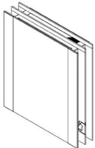
natural_image
Isometric line drawing of a rectangular frame with a small inset detail (no text or symbols)P23Linear
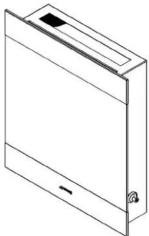
natural_image
Isometric line drawing of a rectangular electronic device with a handle and mounting bracket (no text or symbols)P23Classic
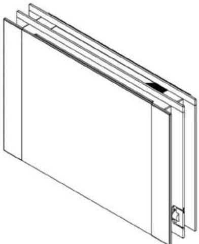
natural_image
Isometric line drawing of a rectangular frame with vertical supports and a small protrusion (no text or symbols)L23Linear
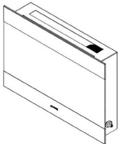
natural_image
Isometric line drawing of a rectangular electronic device with a mounting bracket and internal components (no text or symbols)L23Classic
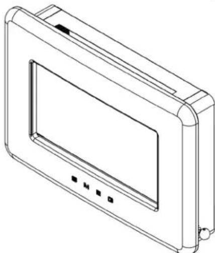
natural_image
Line drawing of a rectangular electronic device with a screen and control buttons (no text or symbols)L30Fab
Please note : Except where otherwise stated, all rights, including copyright in the text, images and layout of this booklet is owned by Smeg S.p.A. You are not permitted to copy or adapt any of the content without the prior written permission of Smeg S.p.A.
This product is tested and approved to ENI4829 : 2007.
All instructions must be handed to the user for safekeeping.
INSTALLATION INSTRUCTIONS
Section Contents Page No.
| 1.0 Important Notes 2 | |
| 2.0 Appliance Data 3 | |
| 3.0 Installation Requirements | 3 |
| 3.1 Room Sizing | 3 |
| 4.0 Site Requirements | 4 |
| 4.1 Ventilation | 4 |
| 5.0 Unpacking the Appliance | 5 |
| 5.1 Component Checklist | 5 |
| 6.0 Gas Supply Routes | 5 |
| 7.0 Fixing the Appliance 6 | |
| 7.1 Checking the Burner & Spark Gap | 6 |
| Section | Contents | Page No. |
| 8.0 | Testing and Commissioning | 6 |
| 8.1 | Operating the Appliance | 7 |
| 8.2 | Setting pressure | 7 |
| 8.3 | Fitting the Decorative Frame | 8 |
| 9.0 | Briefing the customer | 8 |
| 10.0 | Servicing | 8 |
| 10.1 | Servicing the Burner Unit | 9 |
| 10.2 | Pilot Assembly | 9 |
| 10.3 | Catalysts | 10 |
| 10.4 | Testing for Firebox Leakage | 10 |
| 11.0 | Troubleshooting Guide | 11 |
1.0 IMPORTANT NOTES
- This appliance is a high efficiency, flueless catalytic flame effect gas fire. It provides radiant and convected warmth both efficiently and safely utilising the latest type catalytic converter and burner technology.
- The appliance does not require a flue system of any type as the catalytic converter cleans the flue products to provide a complete combustion system, which is intrinsically safe. It is designed to operate on Natural Gas and is factory set for operation on the gas type, and at the pressure stated on the appliance data plate.
- The appliance incorporates a combustion monitoring system (Oxygen Depletion System). It must not be adjusted or put out of operation. If replaced then manufacturer's original parts must be used.
- This appliance must be installed by a competent person to ensure that the size of the room in which the appliance is to be installed is sufficient and the ventilation provision for that room is sufficient for the appliance. Details of how to determine the suitable room size is given in section 3.1 of these instructions and details of how to determine suitable ventilation are given in section 4.1.
- In the event of gas leakage from the appliance, the gas supply must be turned off at the nearest isolating valve.
- The appliance must be installed in accordance with the following:
• Manufacturers' Instructions.
- Local Codes and/or Regulations.
- Failure to comply with the above could lead to prosecution and deem the turer's warranty invalid.
- This appliance must be installed in accordance with the rules in force and in a sufficiently ventilated space. The appliance is designed to fit various types of tions as described in sections 3.0 and 4.0. The appliance must be installed in ly sized room (see section 3.1), and the correct purpose provided ventilation provided (see section 4.1).
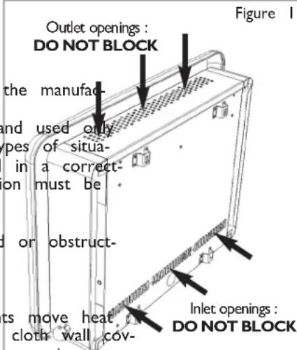
- On no account should the appliance inlet or outlet openings be blocked in any way (see figure 1). Do not place objects on top of the appliance. Do make sure the appliance is installed on a flat wall.
- It should be noted that heaters create warm air currents. These currents to wall surfaces next to the heater. Installing the heater next to vinyl or erings or operating the heater where impurities in the air (such as tobacco dle smoke etc.) exist, may cause the walls to become discoloured.
- This appliance is intended as a secondary source of heat only and should not be used in a room without some form of background heating present. If the appliance is used in a room as the sole source of heat, then condensation may occur on colder surfaces within the room.
- On first light up of a new appliance, burning off of high temperature paint and lubricants may occur for the first few hours of operation. During this period some smoke may be emitted from the outlet grille, this should be no cause for concern. Accordingly, the room should be well ventilated with all windows and doors open during this period. During this period the appliance may cause smoke alarms to sound. If this happens, reset the alarms, but do not remove the batteries.
- WARNING: Due to the nature of this product the area around the top of the appliance (i.e. the grille) gets very hot. Care should be taken when operating the appliance. The manufacturer of this appliance considers all surfaces as working surfaces with the exception of the control knob. The guard (glass front) is to prevent risk of fire or injury from burns and no part of it should be permanently removed. It Does Not Give Full Protection For Young Children Or The Infirm. Where young children, pets, the elderly or infirm are concerned, a suitable fireguard should be used.
- Consult ALL instructions before installation and use of this appliance. This appliance is free from any asbestos material.
o smoke, can- Note : L30FAB shown from rear as example, however the air inlet and outlet openings are in the same relative positions on all models. ld not be used
2.0 APPLIANCE DATA
| P23 MODELS | Cat | Inlet Pressure (mbar) | Max Energy Input (kW) | Min Energy Input (kW) | High Burner Pressure (±1.5 mbar) | Low Burner Pressure (±0.75 mbar) | |||||
| Destination Country | G20 | G25 | Gross | Net Gross | Net | Hot Cold | Hot | Cold | |||
| AT, CH, CZ, HR, ES, FI, GR, IE, IT, NO, SE, SK, | GB/2H TR | 20 | - | 2.0 | 1.8 | 1.0 | 0.9 | 18.7 | 18.6 | 4.1 | 4.0 |
| DE, PL | I_2E | 20 | - | 2.0 | 1.8 | 1.0 | 0.9 | 18.7 | 18.6 | 4.1 | 4.0 |
| BE,FR | I_2E+ | 20 | 25 | 2.0/1.85 | 1.8/1.66 | 1.0/0.92 | 0.9/0.83 | 18.7/23.4 | 18.6/23.5 | 4.1/5.3 | 4.0/5.2 |
| NL | I_2L | - 25 | 1.85 1.66 | 0.92 | 0.83 23.4 | 23.5 | 5.3 5.2 | ||||
| L23 MODELS | Cat | Inlet Pressure (mbar) | Max Energy Input (kW) | Min Energy Input (kW) | High Burner Pressure (±1.5 mbar) | Low Burner Pressure (±0.75 mbar) | |||||
| Destination Country | G20 | G25 | Gross | Net Gross | Net | Hot Cold | Hot | Cold | |||
| AT, CH, CZ, HR, ES, FI, GR, IE, IT, NO, SE, SK, | GB 2H TR | 20 - | 2.0 | 1.8 | 1.3 | 1.17 18.7 | 18.6 7.4 | 7.3 | |||
| DE, PL | I_2E | 20 - | 2.0 | 1.8 | 1.3 | 1.17 18.7 | 18.6 7.4 | 7.3 | |||
| BE,FR | I_2E+ | 20 | 25 | 2.0/1.85 | 1.8/1.66 | 1.3/1.2 | 1.17/1.08 | 18.7/23.4 | 18.6/23.5 | 7.4/9.3 | 7.3/9.2 |
| NL | I_2L | - | 25 | 1.85 | 1.66 | 1.2 | 1.08 | 23.4 | 23.5 | 9.3 | 9.2 |
| L30 MODELS | Cat | Inlet Pressure (mbar) | Max Energy Input (kW) | Min Energy Input (kW) | High Burner Pressure (±1.5 mbar) | Low Burner Pressure (±0.75 mbar) | |||||
| Destination Country | G20 | G25 | Gross | Net Gross | Net Hot Cold | Hot Cold | |||||
| AT, CH, CZ, HR, ES, FI, GR, IE, IT, NO, SE, SK, | GB TR | 20 - | 2.60 2.35 | 1.50 | 1.35 13.7 | 13.6 4.3 | 4.4 | ||||
| DE, PL | ^1_2E | 20 - | 2.60 2.35 | 1.50 | 1.35 13.7 | 13.6 4.3 | 4.4 | ||||
| BE,FR | ^1_2E+ | 20 | 25 | 2.6/2.4 | 2.35/2.15 | 1.5/1.4 | 1.35/1.25 | 13.7/16.9 | 13.6/17.0 | 4.3/5.6 | 4.4/5.5 |
| NL | ^1_2L | - 25 | 2.40 2.15 | 1.40 | 1.25 16.9 | 17 | 5.6 5.5 | ||||
| P23 MODELS | L23 MODELS | L30 MODELS | |
| Flow Restrictor Orifice | 1.03mm | 1.03mm | 1.30mm |
| Oxypilot (Sit/Bray) | 9114 | 9114 | 9114 |
| Gas Control | BM733 | BM733 | BM733 |
| Gas Inlet | Various | Various | Various |
| Ignition | Piezo Spark | Piezo Spark | Piezo Spark |
| Spark Gap ( ± 1.0mm) | 4.0mm | 4.0mm | 4.0mm |
3.0 INSTALLATION REQUIREMENTS
If the appliance is to be sited near a disused or unserviceable fireplace served by a natural draught flue then the old flue must be sealed off. It will be necessary to ventilate the old flue to prevent condensation and dampness forming, however any air vent used to ventilate the old flue must not be sited within 500mm of this appliance. If the flue can be ventilated to the outside of the building then this is usually the best solution. If in doubt then advice should be sought from a local building control officer. The appliance is designed to be wall mounted. If the appliance is to be mounted on a newly fabricated area of wall that also serves the purpose of sealing off the old flue then it is very important that there are no holes, gaps or otherwise in this wall that will allow draughts from the old flue to enter the room, especially directly behind the appliance. Such draughts could affect the performance of the ODS system and result in nuisance cutting out, for example. If the gas supply pipe is to enter the appliance from the rear, i.e. emerge from the wall behind the appliance, then any hole in the wall from which the pipe emerges must be tightly sealed.
3.1 ROOM SIZING
In the absence of any local Codes and/or Regulations governing room sizing for type AIAS appliances then the information given here must be followed.
•P23 and L23 models : The room size should be a minimum (e.gof 3.07m x 3.07m x 2.45m or 10'1" x 10'1" x 8').
•L30 models : The room size should be a minimum (ecf. 305m x 3.5m x 2.45m or 11'6" x 11'6" x 8').
This is to allow adequate circulation of air and ensure the correct operation of the fire. This volume may include adjacent spaces but these spaces must not be separated by a door. Note: To calculate a room size in cubic metres (m ^3 ) divide the room volume in cubic feet ^3 ftby 35.3.
WARNING
This appliance is designed to wall-hung. Do not recess any of the appliance into the wall
This appliance may be installed in any room in the home except bathrooms. If the chance is to be fitted in a bedroom then an electronic carbon monoxide detector (plying with the current edition of BSEN 50291 must be installed in the same room the appliance. For maximum safety it is recommended that such device is continuous (mains) powered and arranged in such a way that the gas supply to the appliance isolated in the event of an alarm. The selection and installation of such device shall in accordance with the current edition of BSEN 50292, and the user must be brought regarding the use and maintenance of such a device.
The appliance is designed to be versatile, and as such will operate correctly when exposed to normal gentle draughts experienced within the home. It is not recommended, however that the appliance be installed in areas where it is likely to be directly exposed to persistent strong draughts, that may be generated by outside doors, windows, air vents, air conditioning units, extractor fans, ceiling fans etc. See section 4.1 for more information on ventilation.
Clearances to non-combustible materials
Non combustible surfaces are defined as brick, metal, marble, concrete etc. and also a number of man-made materials impervious to flame. If in doubt refer to the material manufacturer for further information before proceeding with installation.
Clearances to the sides of the appliance are 100mm (4"). Clearance to the front of the appliance is 500mm (20"). The back of the appliance may be installed directly onto a non-combustible wall, providing the area behind the appliance is flat and does not interfere with the various vent holes in the back panel of the appliance.
A non combustible shelf of any depth may be positioned above the appliance provided it is no closer than 400mm (16") from the top of the appliance glass panel and the wall above the appliance is non combustible. The appliance must not be positioned vertically within 60mm (2.4") of a solid floor (i.e. wood or stone) or hearth. This dimension is measured vertically to the bottom of the appliance firebox.
Clearances to combustible materials
Combustible materials are defined as wood, fabrics, or other materials likely to combust if exposed to flame. Generally, any material, which is likely to discolour, melt or misshape when exposed to moderate heat, should be considered as a combustible material or surface. Clearance to the sides of the appliance are 100mm (4") but curtains, drapes and other fabrics are not permitted within a distance of 500mm (20") of the appliance sides. No such materials are permitted directly above the appliance regardless of distance.
The minimum clearance to the ceiling above the appliance is 800mm (31.5") measured from the top of the appliance glass panel. Combustible materials should not be positioned directly in front of the appliance within a distance of one metre. Under no circumstances should any electrical equipment e.g. plasma/LCD screen TV sets etc. be positioned on the wall above the appliance. The appliance is designed to be wall mounted alone and not in conjunction with any type of combustible fire surround. No combustible shelves should be positioned on the wall above the appliance. It should be established that any mirrors or picture frames etc. to be positioned on the wall above the appliance are able to withstand prolonged exposure to moderate heat and moisture before proceeding with their installation.
The back of the appliance may be installed directly onto a combustible wall, providing it is relatively flat and does not interfere with the various vent holes in the back panel of the appliance. The wall must be structurally sound and constructed from a material capable of withstanding moderate heat. Brick, concrete, finished plaster, most types of conventional wall paper and dry-lined plasterboard are examples of suitable materials. Materials such as flock, blown vinyl and embossed paper which are sensitive to even small amounts of heat should be avoided as scorching and or discolouration may occur over time.
If the appliance is to be mounted on a dry lined wall or a timber framed construction wall then the integrity and ability of the wall to carry the weight of the appliance must be confirmed. It is important in these circumstances that any vapour control barrier is not damaged, and that any structural members of the house frame are not damaged - refer to section 7.0.
The appliance must not be positioned vertically within 100 mm (4") of a carpeted floor, rugs or fabric materials of any kind. This dimension is measured vertically to the bottom of the appliance firebox.
4.1 VENTILATION
GB only: A minimum of 100 purpose provided ventilation MUST be provided for this appliance. This may be achieved either with one vent 100 ama high or low position in the room, or split ventilation bee insted at high level and 50cm be installed at low level within the room. An openable window or equivalent is also required. To reduce the | of draughts, road noise or insects entering the room via the air vent, we recommend the use an air vent of the type that feature internal baffles.
IE only : Refer to the current edition of IS813.
The requirements of any other gas, oil or solid fuel appliances operating in the same room or space must be taken into consideration when assessing ventilation.
Any ventilation fitted must comply with any relevant local codes for the installation of ventilation.
Ventilation fitted under, or within immediate vicinity of the appliance must not be used as it may adversely effect performance of the ODS system. The appliance shall not be installed within 1 metre of any existing air vent, and any new air vent shall not be installed within 1 metre of the appliance.
Note : With the appliance installed in the minimum size room and with the ventilation specified, the concentration of NO2 in the room is less than 300ppb.
5.0 UNPACKING THE APPLIANCE
Remove the outer packaging, remove any instructions or fixing kits. Read ALL these instructions before continuing to unpack or install this appliance. Lift off the remaining packaging components and remove the contents of the box. Check that the components supplied correlate with the component checklist. Please dispose of all the packaging materials at your local recycling centre.
5.1 COMPONENT CHECKLIST
QUANTITY DESCRIPTION
I Firebox and burner assembly
I Set of manufacturers instructions
I Decorative glass facia assembly (Linear and Classic models)
I Painted decorative facia in one of several colours (Fab models)
I Screw and wall plug pack
I Rubber grommet
I Fitting template
6.0 GAS SUPPLY ROUTES
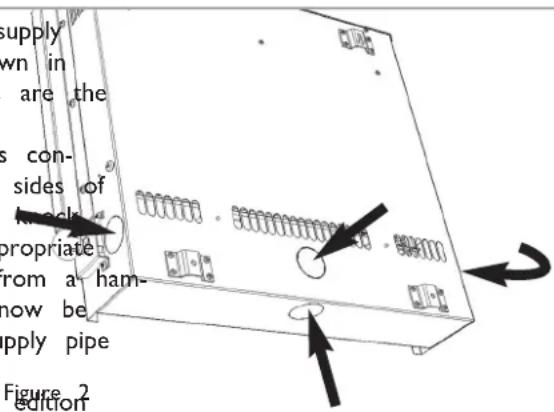
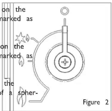
All models: There are four possible entry points for the gas supply pipework to enter the appliance firebox. The L23 firebox is shown in figure 2 as an example, but the relative locations of these holes are the same for all models.
These entry points are 'knock out' type holes. Non-concealed gas connections may be made using the entry points in the bottom or sides of the firebox. A concealed gas connection may be made using the knock-out hole in the centre back of the firebox. Select the most appropriate entry point and knock out the relevant hole with a sharp tap from a hammer and fit the rubber grommet supplied. A small incision can now be made in the rubber to slip snugly around the outside of the supply pipe and sleeving.
All installation pipework must be in accordance with the current edition of National regulations/codes and the rules in force.
In order to avoid unnecessary pressure drops, use of small diameter pipe should be kept to a minimum, for example, we recommend no more than 1.5 metres of 8mm pipe. If a concealed gas connection is to be made, the supply pipe should always be sleeved through walls and floors using the shortest possible route. For concealed supply pipe routing, pipes must (where possible) be vertical and providing there is sufficient wall thickness available, they should be placed in pipe chases. Horizontal pipe runs should be avoided. Prior to chasing a solid wall, an inspection should be made to note the proximity of any cables/sockets outlets which may already be buried. Pipes must be secured using suitable clips and protected against corrosion. Ideally factory finished protected pipework and fittings should be used. Joints should be kept to a minimum and compression fittings must not be used. The pipework installation must be tested for tightness before any protection is applied and/or the pipework and fittings are buried.
7.0 FIXING THE APPLIANCE
Remove any protective film coatings from the finished/decorative surfaces of the appliance. After having selected the final mounting position of the appliance, taking into account the requirements as specified in sections 3 and 4 of these instructions, the

WARNING
The wall where the appliance to be installed must be capable of long-term support of the load of the appliance. Measure should also be taken to ensure sufficient strength to withstand the force of earthquakes, vibration and other external forces
integrity of the wall, and the feasibility of the proposed supply pipe routing, the f of the appliance may be secured to the wall.
To ensure customer safety, be sure to design the installation so that the strength both the wall and any wall fixings used are sufficient.
Sreg S.p.A. assumes absolutely no responsibility for injuries and damages that may occur due to improper installation or handling. The appliance should not be installed until all wet plastering and/or dry wall sanding and wall painting has been complete. Do not block the ventilation holes of the appliance. The wall onto which the app is installed must be flat. Install only on a vertical surface. Avoid sloped surfaces. Installation onto anything other than a vertical wall may result in fire, damage or
If the appliance is to be mounted on the inner leaf of a conventional cavity brick wall, or a solid wall, then the wall plugs and fixing screws provided may be used. Depending on the condition of the wall it may be necessary to use additional fixings. In this situation, any additional fixings and wallplugs should be of the same size and type as the ones provided. At the appropriate stage of the installation, drill four holes using only a 8mm masonry bit to a depth of 42mm. Insert the wallplugs provided ensuring they are flush to the wall.
7.0 FIXING THE APPLIANG(NTINUED)

WARNING
Plasterboard alone is not cons ered to be a structural mate It is not recommended to re plasterboard fixings alone to s port the weight of the applia
If the appliance is to be mounted on a dry lined wall or a timber framed construction wall then efforts should be made to fix in at least two positions vertically, into one of the wooden studs, or supporting wooden members of the wall using two of the fixing screws provided. If this is not achievable then
Figure 3
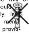
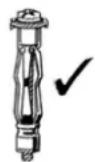
ened using appropriate building materials. If there is no alternative than to rely on some plasterboard fixings then special cavity screw fixings or hollow wall anchors will be required which are not supplied with this product. These should be constructed from metal and not plastic and of the design indicated in figure 3. For further guidance for wall fixing in timber framed buildings refer to any relevant local codes of practice.
Flat Wall Fixing - All Models
To assist with fixing the appliance, a template is provided. The template is shown for the purposes of example in figure 4. Mark the positions shown as “Fixing points” on the wall.
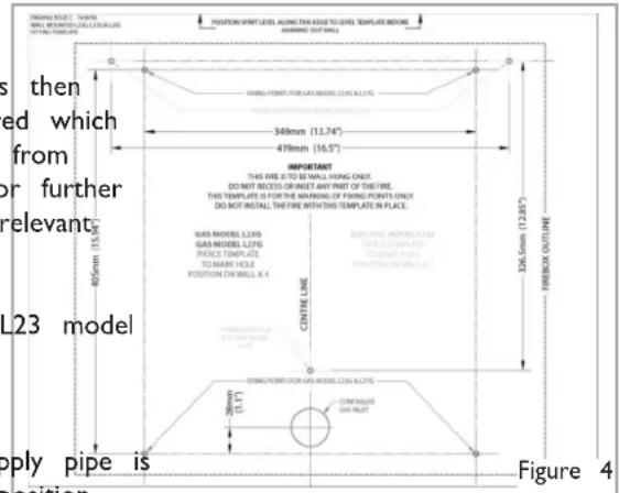
If a concealed gas connection is to be made ensure the gas supply pipe in its final position and can enter the appliance in the correct position when the appliance is hung on the wall.
Drill the wall as appropriate for the type of wall as previously described in this section, and insert the chosen type of wall fixings. Insert the wall fixing screws into the top wall plugs, taking care to leave the screws protruding approximately 5mm from the wall. Now hang the appliance onto these screws through the two keyhole shaped holes in the upper brackets on the back panel of the appliance.
Insert the lower fixing screws into the lower wall plugs through responding fixing holes in the lower part of the back panel. Do en fully.
Before tightening the wall mounting screws fully, at this stage it is recommended to check the horizontal alignment of the appliance with a spirit
level, as small adjustments can still be made if necessary. When this has been checked, tighten all four fixing screws fully.
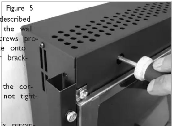
To access the upper fixing screws insert a screwdriver through the round access holes in the front face of the outlet grille (as shown in figure 5). These access holes are located in the same position on all models.
7.1 CHECKING THE BURNER AND SPARK GAP
There are no imitation fuel bed components to install. The appliance features a ribbon burner which is designed to produce a continuous band of flame over its length.
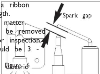
The burner should be visually inspected to ensure it is free from any foreign matter. If it is necessary to clean or dust off the burner then the glass door should be removed by removal of the four retaining screws. Re-fit the glass door after cleaning or inspection, ensuring a good seal. The gap between the spark electrode and the pilot should be 3 - 5mm to produce a good spark (see figure 6).
There should be no need to adjust this. If under any circumstances the piezo spark fails, the pilot cannot be lit manually.
8.0 TESTING AND COMMISSIONING
The appliance is supplied with a selection of inlet adaptors for use in the various countries of destination. Select an appropriate adaptor and connect to the flared inlet connection of the appliance. Ensure the inlet adaptor/connection is fully tightened. Turn on and test the gas supply up to the fire for any leaks, in accordance with local Codes and/or Regulations.
8.1 OPERATING THE APPLIANCE
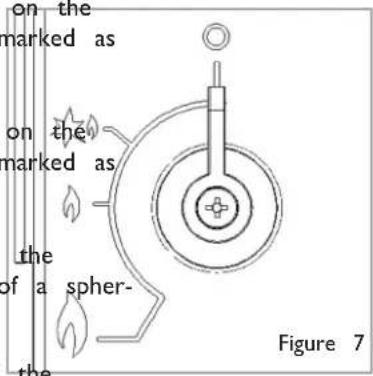
Classic models : The control knob is located on the lower right hand side of the outer case. It is marked as shown in figure 7;
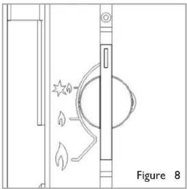
Linear models : The control knob is located on the lower right hand side of the outer case. It is marked as shown in figure 8;
Fab models : The control knob is located on the lower right hand side of the outer case. It is of a spherical design and is marked as shown in figure 9;
natural_image
Technical line drawing of a door with a circular component and flame symbols, labeled Figure 8 (no text or symbols on the diagram itself)The pilot is visible behind the left hand side of the burner. Push in and turn the control knob to the SPARK position, and hold there for a few seconds. Continue turning anti-clockwise through the spark click to the PILOT light position, ensuring the pilot has lit. If not, return the knob clockwise, and repeat.
When the pilot lights after the spark, keep the knob pressed for approximately ten seconds. Now release the knob and the pilot should stay alight. If the pilot is extinguished during use, wait three minutes before repeating the ignition procedure.
To achieve the HIGH setting, push the control knob in slightly and continue turning anti- 'LOW' position clockwise to the high position. The main burner should light after a few seconds. To decrease the setting to low, turn the control knob clockwise to the LOW setting.
To turn to the PILOT position from the HIGH or LOW positions, press the control knob in, and return to the pilot position and release. To turn the fire off, keep the knob pressed in, return to the OFF position and release.
8.2 SETTING PRESSURE
All models : The pressure test point is located on the left hand side of the appliance, on the main burner pipe, next to the brass restrictor/connector. Remove the burner cover plate to access, by removal of the four retaining screws as shown in figure 10. Release the setting pressure test point screw (shown in figure 11), and attach a pressure gauge. Light the fire on the HIGH setting. Figure 10
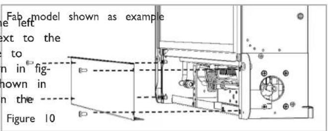
To commission the appliance, the burner pressure must I accordance with the figures stated in section 2.0 of these instructions. The fire is factory set to achieve these pres and any significant variation could indicate a supply problem the pressure is too high, the gas supply meter may be rectly. This should be checked with the fire running and essary reset by the gas supplier.
If the burner pressure is too low, then check the inlet with the appliance running. If this is less than the inlet stated in section 2.0 of these instructions it will need to by the gas supplier. If the setting pressure is too low, meter pressure is acceptable, then a problem in the sup-pipework is to be suspected.
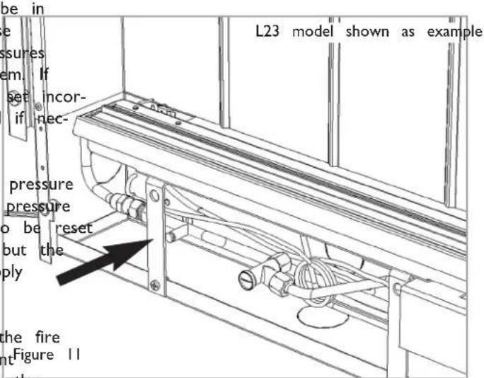
Upon satisfactory checking of the burner pressure, turn the fire off, disconnect the pressure gauge and refit the test point Figure 11 screw. Light the fire and check for gas soundness. Re-fit the burner cover plate, and replace the four retaining screws.
In the event that the burner pressure is not in accordance with the figures stated in the data section of these instructions, the appliance must not be commissioned, and the manufacturer should be contacted for guidance.
8.3 FITTING THE DECORATIVE FRAME ASSEMBLY GBIE
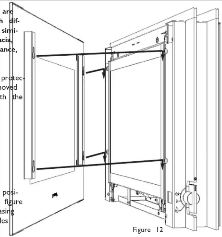
Please note that the Linear and Classic models are supplied with a tinted glass facia assembly, which differ in appearance when viewed from the front, similarly the Fab model is supplied with a metal facia, however the method of attachment to the appliance, for all frame designs, is the same.
All models : Remove the facia panel from any protective packaging. Ensure all/any protective film is removed as the facia may be damaged if the fire is lit with the facia in position whilst still covered in film.
The facia panel is supported by four M6 screws which protrude from the front of the outer casing as shown figure 12. Ensure each screw is unscrewed
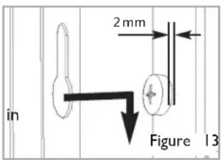
approximately one turn from the fully screwed in position in order to create a 2mm gap as shown in figure 13. Simply hang the facia panel onto the outer casing ensuring that the corresponding keyhole shaped holes engage the screwheads fully.
9.0 BRIEFING THE CUSTOMER
All instructions must be handed to the user for safekeeping. Show the customer how to light and control the fire. After commissioning the appliance, the customer should be instructed on the safe use of the appliance and the need for regular servicing. Frequency of service depends on usage, but MUST be carried out at least once annually.
Advise that cleaning of the fire may be achieved when the fire is cold using a damp cloth and mild detergent on most surfaces. Advise that on first light up of a new appliance, initial curing of high temperature paint and burning off of lubricants may occur for the first few hours of operation. During this period some smoke may be emitted from the outlet grille, this should be no cause for concern. Accordingly, the room should be well ventilated with all windows and doors open during this period. During this period the appliance may cause smoke alarms to sound. If this happens, reset the alarms, but do not remove the batteries.
Recommend that a guard be used for the protection of the young, pets, the elderly and the infirm.
Advise the customer that the ventilation openings should not be blocked or obstructed in any way.
10.0 SERVICING
Isolate the fire from the gas supply. Ensure that the fire is fully cold before attempting service. A suggested procedure for servicing is detailed below.
- Lay out the dustsheet and tools.
- Remove the decorative frame/glass facia assembly. Removal is reverse of section 8.3.
- Remove the glass door assembly (4 screws) and clean carefully.
- Inspect the burner and the catalyst and clean if necessary with a soft brush.
- Disconnect the gas supply.
- Detach the burner front cover plate by removal of the four retaining screws. Undo the two screws retaining the support bracket to the base and rear of the firebox. Remove the four screws retaining the valve bracket to the 1 Remove the control knob and spindle assembly from the valve by removal of the spindle retaining clip.
- Remove the burner unit, strip off the burner pipes and clean thoroughly.
- Clean the in-line restrictor, pilot assembly and the burner tube. Do not attempt to remove the pilot injector as this can cause damage.
- Re-assemble components.
- Turn on the gas supply and leak test. Check pilot and burner for good ignition.
II. Refit the glass door assembly, ensuring correct orientation and a good seal. - Refit the decorative facia/frame assembly as detailed in section 8.3.
- Check the purpose provided ventilation is un-obstructed.
- Light the fire and test setting pressures.
- Check safe operation of the appliance.
Forspecificservicinginstructions,seerelevantsections.
All models : Firstly, remove the decorative
frame/glass facia assembly as described in section
8.3. Remove the inner glass panel, and disconnect the gas connection inside appliance. The gas connections to the gas valve can now be released. Detach the burner front cover plate by removal of the four retaining screws (as shown in figure 10, section 8.2). Remove the control knob and spindle assembly from the valve by removal of the spindle retaining clip.
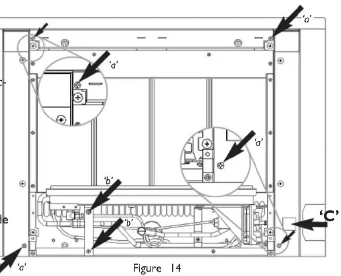
Classic and Linear models : To remove the outer casing (sides and top), remove the four retaining screws designated 'a'in figure 14. Pull the casing forward slightly and then lift the entire casing assembly upwards and remove.
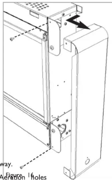
Fab models : To remove the right hand casing side panel, remove the two screws shown in figure 16, then pull the right hand side forward and then sideways. Note - to remove the burner it is only necessary to remove the right hand side panel. The same method is used should it be necessary to remove the left hand panel.
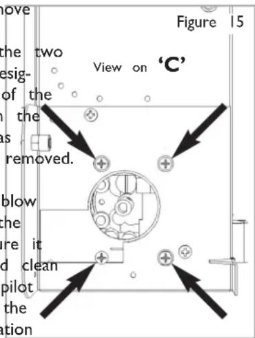
All models : To remove the burner, undo the two screws retaining the burner support bracket (designated 'b' in figure 14) to the base and rear of the firebox, and undo the four retaining screws on the right hand side panel, near the control valve as shown in figure 15. The burner may now be removed
Remove the pilot and main burner pipes and blow through to dislodge any debris. Now remove the restrictor elbow and blow through to make sure it is entirely clear. Unclip the pilot lint gauze and clay with a soft brush. Clean the exterior of the pilot assembly with a soft brush and blow through the flame ports on the pilot head. Check the aeration holes are free from lint or dirt. The pilot assembly can be removed if required by disconnecting the electrode HT lead, gas pipe and unscrewing the mounting screws and lifting away.
The pilot assembly is a non-serviceable item and should not be taken apart. Aeration holes must be absolutely clear internally for proper operation. NEVER MODIFY OR BEND
THE THERMOCOUPLE TO MAKE THE PILOT STAY ALIGHT. Modifications are
dangerous and can have serious unseen effects on safety. If the pilot will not stay lit there is a problem with dirt, the gas supply to it, or the thermocouple needs replacement.
The gas valve is a non-serviceable item. If this needs replacement, remove M4 securing screw holding the valve in place, remove all pipe unions, electrode lead, thermocouple lead and then the complete valve. Replacement must be original manufacturers parts. Re-assembly is the reverse of removal. Ensure setting pressures are as stated in Section 2; Appliance Data.
10.2 PILOT ASSEMBLY
Remove the burner unit as detailed in section 10.1, then remove the lint arrestor and pilot unit by using a screwdriver to remove the retaining screws. Clean the pilot assembly with a soft brush and blow through. Check the aeration holes are free of any dirt or lint. Clean thoroughly internally, the connection can be removed from the base of the pilot unit using two spanners to make cleaning easier. Do not damage or try to dismantle the pilot injector.
The unit is factory set and the only check necessary is to ensure the spark gap is correct. See specifications for gap setting.
NEVER MODIFY OR BEND THE THERMOCOUPLE TO MAKE THE PILOT STAY ALIGHT. If the pilot will not stay lit there is a problem with dirt, the gas supply, or the thermocouple needs replacement. Modifications are dangerous and can have a serious unseen effect on safety and therefore MUST not be done. Replacements must be original manufacturers parts assembly is the reverse of removal. Ensure setting pressures are as stated in Section 2; Appliance Data.
10.3 CATALYSTS
It is recommended that the catalysts are inspected for signs of damage and dirt during routine servicing procedures. The expected life of the catalysts is in excess of 11,000 hours (10 years of normal use). After this time the catalysts should be replaced.
If there are any deposits of dirt or soot on the catalyst they should be cleaned with a soft brush and a vacuum cleaner. If removed for cleaning ensure the seals are in good condition before replacing the catalyst. New seals will usually be required.
The performance of the catalysts may be checked using a combustion gas analyser as follows. Any analyser used should conform to EN 50379-3.
Ignite the fire as per the operating instructions, and run at maximum setting for 15 minutes. Position gas sample probe directly over the catalysts via the outlet grille, on top of the appliance. Record the carbon dioxide (CO2) concentration and then the carbon monoxide (CO) concentration as displayed by the analyser - also noting the units in which the values are expres
Most analysers display carbon dioxide (CO2) concentrations in percentage (%) terms and carbon monoxide concentration parts per million (ppm) terms.
In order to calculate the combustion ratio for the appliance (CO/CO2) it is first necessary to express both gas concentrations in terms of percentage. To convert from parts per million (ppm) to a percentage (%) divide the ppm figure by 10,000. Examples: 35ppm = 0.0035%, 15ppm = 0.0015%, 5ppm = 0.0005%. Now divide the concentration of carbon monoxide (CO) ex percent by the concentration of carbon dioxide (CO2) to obtain the appliance combustion ratio.
$$ \frac {\mathrm{CO} (\%)}{\mathrm{CO2} (\%)} = \text { ratio } $$
The combustion ratio of the gasses emitted by the catalytic convertor should not exceed 0.0015. If replacing, firstly, remove the decorative frame/glass facia (as described in section 8.3) and outer casing. The catalysts are located on the top of the internal firebox and can be removed by unscrewing the retaining nuts securing the clamping plates. Remove the catalysts their seals and discard. Refit the new catalysts and seals in reverse order, ensure the catalysts and the glass door have good seals.
10.4 TESTING FOR FIREBOX LEAKAGE
Appliances that are several years old or have been extensively dismantled should be checked for soundness. It is important that all the products of combustion pass through the catalytic converter at the top of the firebox before leaving the appliance.
The firebox is heated by lighting for a few minutes to provide a flow through the firebox. The burner is then shut off and a smoke pellet or match introduced at the base of the fire underneath the burner tray. Large quantities of smoke will emerge from the top of the appliance, but none should emerge from the joints or gasket faces, especially around the door.
It is important to note that the appliance can never be expected to be 100% smoke tight and small quantities of smoke may be seen in corners of joints and gasket faces etc without affecting safety when the fire is in operation.
Fire sparks but pilot does not light No gas to fire, check isolators are open.
Pipe work blockage, clean out.
Air not fully purged, re purge supply or wait longer.
Spark earthing to metal work, reset gap correctly.
Blocked pilot, clean out internally.
Pilot lights but then goes out Severe restriction in gas supply: clear obstruction.
Faulty thermocouple, replace pilot unit.
Blocked pilot, clean out.
Blocked lint gauze, clean.
Hold control knob in for longer.
Check control knob does not foul indicator plate.
If the pilot will not stay lit there is a problem with dirt, the gas supply, or the thermocouple needs replacement.
Modifications are dangerous and can have a serious unseen effect on safety. NEVER MODIFY OR BEND THE THERMOCOUPLE TO MAKE THE PILOT STAY ALIGHT.
Fire does not spark at pilot HT lead detached, refit.
Check the spark gap (see section 7.1).
Faulty piezo unit, replace.
Debris shorting out electrode, clean.
Spark shorting to metalwork under tray, realign HT lead.
Fire runs for a time and then cuts off Loose or faulty thermocouple, rectify.
Blocked pilot, clean out.
Dirt or lint in pilot aeration hole or on the lint gauze, clean thoroughly.
If the pilot will not stay lit there is a problem with dirt, the gas supply, or the thermocouple needs replacement.
Modifications are dangerous and can have a serious unseen effect on safety. NEVER MODIFY OR BEND THE THERMOCOUPLE TO MAKE THE PILOT STAY ALIGHT.
Pilot flame shrinks when fire is on high
Poor gas flow to fire, check pressure with fire on high.
If pressure is low, remove any restriction in pipework or valve.
Check all isolators are adequately sized and fully open.
Check meter pressure is adequate.
If the pilot will not stay lit there is a problem with dirt, the gas supply, or the thermocouple needs replacement.
Modifications are dangerous and can have a serious unseen effect on safety. NEVER MODIFY OR BEND THE THERMOCOUPLE TO MAKE THE PILOT STAY ALIGHT.
Fire smells when first lit or in use Newness smell from brand new appliance.
Leakage occurring. Carry out leakage test and rectify any problems.
Combustible materials used in incorrect positions.
| Section | Content | Page No |
| 1.0 | Important Notes | 1 |
| 2.0 | Clearances to Combustibles | 1 |
| 3.0 | Ventilation & Room Size | 2 |
| 4.0 | Operating Instructions | 3 |
| 5.0 | Combustion Monitoring System | 3 |
| 6.0 | Cleaning | 3 |
| 7.0 | Servicing | 4 |
| 8.0 | List of Replacement Parts | 4 |
| 9.0 | Installation Details | 4 |
| 10.0 | Service History | 4 |
| 11.0 | Appliance Dimensions | Inside rear cover of booklet |
1.0 IMPORTANT NOTES
- The installation and Servicing of this fire MUST only be carried out by a competent person in accordance with local Codes and/or Regulations, Building Regulations and the manufacturer's instructions. Failure to comply with the above could lead to prosecution and invalidate the appliance warranty. In the event of gas leakage from the appliance, the gas supply must be turned off at the nearest isolating valve. This appliance is only suitable for the gas type for which it is supplied.
- Keep a note of the installer's name and address, the original purchase receipt and the date of installation. Failure to produce this information may invalidate the warranty. The appliance should be serviced regularly to ensure continued safe operation. See the servicing section for further reference.
- The guard (glass front) is to prevent risk of fire or injury from burns and outlears it should be permanently removed. It Does Not Give Full Protection FoDO Young Children Or The Infirm. Parts of this appliance become naturally hot during use. It is recommended that a suitable fireguard is used, especially where young children, pets, the elderly or infirm are concerned. The manufacturer of this appliance considers all surfaces as working surfaces with the exception of the control knob and control panel. Combustible items, such as flooring and furniture and soft wall coverings (such as blown vinyl or embossed paper), low temperature surrounds etc may discolour if fitted too close to the fire. See relevant section for further details on clearances to combustibles. No combustible materials or flooring should protrude onto the hearth (if fitted).
- This appliance incorporates a combustion monitoring system (ODS).
- DO NOT burn any foreign material on this fire. Under no circumstances shall the appliance be used if the glass front door or panel has been removed, damaged or is open. On no account should the appliance inlet or outlet openings be blocked or obstructed in any way (see figure 1). DO NOT place objects on top of the appliance.
- WARNING: Due to the nature of this product the area around the top of the appliance (i.e. the grille) gets very hot. Care should be taken when operating the appliance. The integral catalysts should be checked by the installer upon servicing to ensure there are no defects or obstructions that may prevent the satisfactory flow of combustion products. The expected life of the catalyst is in excess of 11,000 hours (10 years of normal use). After this time the catalyst should be replaced.
2.0 CLEARANCES TO COMBUSTIBLES
Clearances to non-combustibles
Non combustible surfaces are defined as brick, metal, marble, concrete etc. and also a number of man-made materials impervious to flame. If in doubt refer to the material manufacturer for further information before proceeding with installation.
Clearances to the sides of the appliance are 100mm (4"). Clearance to the front of the appliance is 500mm (20").
The back of the appliance may be installed directly onto a non-combustible wall, providing the area behind the appliance is flat and does not interfere with the various vent holes in the back panel of the appliance.
A non combustible shelf of any depth may be positioned above the appliance provided it is no closer than 400mm (16") from the top of the appliance glass panel and the wall above the appliance is non combustible.
The appliance must not be positioned vertically within 60mm (2.4") of a solid floor (i.e. wood or stone) or hearth. This dimension is measured vertically to the bottom of the appliance firebox.
Clearances to combustible materials
Combustible materials are defined as wood, fabrics, or other materials likely to combust if exposed to flame. Generally, any material, which is likely to discolour, melt or misshape when exposed to moderate heat, should be considered as a combustible material or surface.
Clearance to the sides of the appliance are 100mm (4") but curtains, drapes and other fabrics are not permitted within a distance of 500mm (20") of the appliance sides. No such materials are permitted directly above the appliance regardless of distance.
The minimum clearance to the ceiling above the appliance is 800mm (31.5") measured from the top of the appliance glass panel.
Combustible materials should not be positioned directly in front of the appliance within a distance of one metre.
Under no circumstances should any electrical equipment e.g. plasma/LCD screen TV sets etc. be positioned on the wall above the appliance. The appliance is designed to be wall mounted alone and not in conjunction with any type of combustible fire surround. No combustible shelves should be positioned on the wall above the appliance. It should be established that any mirrors or picture frames etc. to be positioned on the wall above the appliance are able to withstand prolonged exposure to moderate heat and moisture before proceeding with their installation.
The back of the appliance may be installed directly onto a combustible wall, providing it is relatively flat and does not interfere with the various vent holes in the back panel of the appliance. The wall must be structurally sound and constructed from a material capable of withstanding moderate heat. Brick, concrete, finished plaster, most types of conventional wall paper and dry-lined plasterboard are examples of suitable materials. Materials such as flock, blown vinyl and embossed paper which are sensitive to even small amounts of heat should be avoided as scorching and or discolouration may occur over time.
If the appliance is to be mounted on a dry lined wall or a timber framed construction wall then the integrity and ability of the wall to carry the weight of the appliance must be confirmed. It is important in these circumstances that any vapour control barrier is not damaged, and that any structural members of the house frame are not damaged - refer to section 7.0 of the installation section of these instructions.
The appliance must not be positioned vertically within 100 mm (4") of a carpeted floor, rugs or fabric materials of any kind. This dimension is measured vertically to the bottom of the appliance firebox.
3.0 VENTILATION & ROOM SIZE
Purpose provided ventilation of 100mMUST be provided for this appliance. An openable window or equivalent is also required. Any ventilation fitted must comply with local Codes and/or Regulations. Ventilation fitted under, or within immediate vicinity of the appliance must not be used as it may adversely effect performance of the combustion monitoring system (ODS) system. The appliance shall not be installed within 1 metre of any existing air vent, and any new air vent shall not be installed within 1 metre of the appliance. Ventilation openings should never be blocked or restricted in any way.
The requirements of other appliances operating in the space or room must be taken into consideration when assessing ventilation requirements, this will have been carried out by your installer. A supply of fresh air into the room is advisable to maintain temperatures within limits.
•P23 and L23 models : The room size should be a minimum.e.gof3.07m x 3.07m x 2.45m or 10'1" x 10'1" x 8').
•L30 models : The room size should be a minimum ^3 (og. 30.5m x 3.5m x 2.45m or 11'6" x 11'6" x 8').
This is to allow adequate circulation of air and ensure the correct operation of the fire. This volume may include adjacent spaces but these spaces must not be separated by a door. Note: To calculate a room size in cubic metres ( m^3 ) divide the room volume in cubic feet (ft3) by 35.3.
It should be noted that heaters create warm air currents. These currents move heat to wall surfaces next to the heater. Installing the heater next to vinyl or cloth wall coverings or operating the heater where impurities in the air (such as tobacco smoke, candle smoke etc.) exist, may cause the walls to become discoloured.
This appliance is intended as a secondary source of heat only and should not be used in a room without some form of background heating present. If the appliance is used in a room as the sole source of heat, then condensation may occur on colder surfaces within the room.
4.0 OPERATING THE APPLIANCE
Classic models : The control knob is located on the lower right hand side of the outer case. It is marked as shown in figure 2;
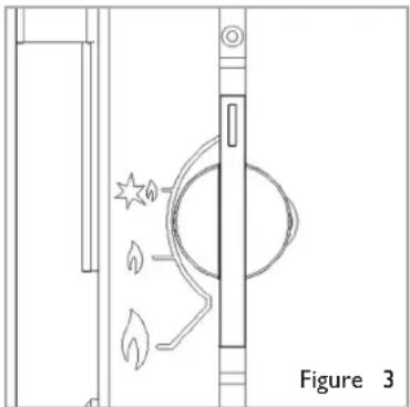
Linear models : The control knob is located on the lower right hand side of the outer case. It is marked as shown in figure 3;
Fab models : The control knob is located on lower right hand side of the outer case. It is of ical design and is marked as shown in figure 4;
natural_image
Technical line drawing of a door with a circular component and flame-like symbols, labeled Figure 3 (no text or symbols on the diagram itself)The pilot is visible behind the left hand side of the burner. Push in and turn the control knob to the SPARK position, and hold there for a few seconds. Continue turning anti-clockwise through the spark click to the PILOT light position, ensuring the pilot has lit. If not, return the knob clockwise, and repeat.
When the pilot lights after the spark, keep the knob pressed for approximately ten seconds. 'SPARK' position Now release the knob and the pilot should stay alight. If the pilot is extinguished during use, wait three minutes before repeating the ignition procedure.
To achieve the HIGH setting, push the control knob in slightly and continue turning anticlockwise to the high position. The main burner should light after a few seconds. To decrease the setting to low, turn the control knob clockwise to the LOW setting.
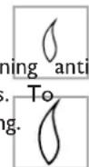
'LOW' position
'HIGH' position
To turn to the PILOT position from the HIGH or LOW positions, press the control knob in, and return to the pilot position and release. To turn the fire off, keep the knob pressed in, return to the OFF position and release.
Figure 4
5.0 COMBUSTION MONITORING SYSTEM
This fire is fitted with a combustion monitoring safety device (ODS). If the appliance shuts down during use for no apparent reason then several reasons may be suspected.
If a door or window has been opened creating a draught, then pilot disturbance could be the problem and removal of the draught should resolve this. The appliance can then be re-lit in accordance with the previous section. If pilot disturbance is not the cause, then the ODS safety system may be in operation. Switch the appliance OFF, call in your installer to check the appliance and ventilation. Remedial work must be carried out as required. DO NOT allow the appliance to be used until the appliance and installation is passed as safe.
If the pilot continues to be extinguished, you must call your installer to check the operation of the complete appliance.
6.0 CLEANING
Before carrying out any of the following operations, ensure that the appliance is OFF and completely cold.
Regularly clean around the appliance to ensure that dust, fluff, pet hair etc, are kept to a minimum. There are no other specific requirements for care, other than regular cleaning of the general appliance. A wipe with a dry cloth is normally sufficient. DO NOT use abrasive cleaners as they can damage the finish. Metal parts may be cleaned using an appropriate metal cleaner. Test on a hidden part before cleaning. Clean only in the direction of the grain.
GLASS PANEL - This can be cleaned with a suitable glass cleaner. Test on a small area first.
PAINTED AREAS - These can be cleaned using a dry cloth.
FINISHED METAL AREAS - These can either be cleaned using a proprietary metal cleaner. Test on a small hidden pa cleaning. Always clean in the direction of the grain.
7.0 SERVICING
The appliance should be checked on an annual basis to ensure it is working safely and that there is no excessive build up of soot. The frequency of service will depend on usage, but MUST be carried out at least once annually. Servicing must be carried out by a competent person.
8.0 LIST OF REPLACEMENT PARTS
The Installation instructions carry full servicing details for the use of the installer.
PART NO. ITEM
F960001 Inner glass door assembly (P23 models)
F960002 Inner glass door assembly (L23 models)
F960003 Inner glass door assembly (L30 models)
F730038 Pilot assembly
FT003155/2 Gas valve
Please Enquire Burner unit
F780079 Catalyst (seal kit must also be supplied)
F940136 Seal kit for Catalyst
9.0 INSTALLATION DETAILS
Model :
Date installed :
Fire serial No. :
Name & contact details of installer :
Supplied by :
10.0 SERVICE HISTORY
| Date of service | Serviced by : | Contact details of Engineer |
- INSTALLATION & USER INSTRUCTIONS
- WALL MOUNTED HIGH EFFICIENCY GAS FIRE
- INSTALLATION INSTRUCTIONS
- IMPORTANT NOTES
- APPLIANCE DATA
- INSTALLATION REQUIREMENTS
- ROOM SIZING
- WARNING
- Clearances to non-combustible materials
- Clearances to combustible materials
- VENTILATION
- UNPACKING THE APPLIANCE
- COMPONENT CHECKLIST
- QUANTITY DESCRIPTION
- GAS SUPPLY ROUTES
- FIXING THE APPLIANCE
- FIXING THE APPLIANG(NTINUED)
- Flat Wall Fixing - All Models
- CHECKING THE BURNER AND SPARK GAP
- TESTING AND COMMISSIONING
- OPERATING THE APPLIANCE
- SETTING PRESSURE
- FITTING THE DECORATIVE FRAME ASSEMBLY GBIE
- BRIEFING THE CUSTOMER
- SERVICING
- PILOT ASSEMBLY
- CATALYSTS
- TESTING FOR FIREBOX LEAKAGE
- CLEARANCES TO COMBUSTIBLES
- Clearances to non-combustibles
- VENTILATION & ROOM SIZE
- OPERATING THE APPLIANCE
- COMBUSTION MONITORING SYSTEM
- CLEANING
- SERVICING
- LIST OF REPLACEMENT PARTS
- PART NO. ITEM
- INSTALLATION DETAILS
- SERVICE HISTORY
Brand : SMEG
Model : P23LINP
Category : Fireplace