EDS8PS - Server Lantronix - Free user manual and instructions
Find the device manual for free EDS8PS Lantronix in PDF.


| Type of product | Device Server |
| Model | EDS8PS |
| Brand | Lantronix |
| Number of serial ports | 8 |
| Ethernet interface | 10/100/1000 Mbps |
| Power input | 12V DC or PoE (IEEE 802.3af) |
| Operating temperature | 0°C to 50°C |
| Dimensions (W x D x H) | 4.5 x 3.0 x 1.2 inches |
| Weight | 0.5 kg (approx.) |
| LED indicators | Power, Link, Activity |
| Supported protocols | TCP/IP, UDP, Telnet, SSH, HTTP, HTTPS |
| Security features | SSL/TLS encryption, password protection |
| Configuration | Web interface, CLI, DeviceInstaller utility |
| Power consumption | 5W typical |
| Certifications | FCC, CE, RoHS |
| Warranty | 2 years limited |
| Maintenance | Clean with dry cloth; avoid liquids |
| Safety precautions | Do not open the device; risk of shock |
| Spare parts and reparability | Contact Lantronix support for replacements |
Frequently Asked Questions - EDS8PS Lantronix
User questions about EDS8PS Lantronix
0 question about this device. Answer the ones you know or ask your own.
Ask a new question about this device
Download the instructions for your Server in PDF format for free! Find your manual EDS8PS - Lantronix and take your electronic device back in hand. On this page are published all the documents necessary for the use of your device. EDS8PS by Lantronix.
USER MANUAL EDS8PS Lantronix
natural_image
Stacked network equipment including LANTRONIX and EDS ports, showing Ethernet, Ethernet, and network ports (no readable text or symbols)EDS Device Servers and Terminal Servers
User Guide
© 2009 Lantronix. All rights reserved. No part of the contents of this book may be transmitted or reproduced in any form or by any means without the written permission of Lantronix. Printed in the United States of America.
Ethernet is a trademark of XEROX Corporation. UNIX is a registered trademark of The Open Group. Windows 95, Windows 98, Windows 2000, and Windows NT are trademarks of Microsoft Corp. Netscape is a trademark of Netscape Communications Corporation.
Contacts
Lantronix Corporate Headquarters
15353 Barranca Parkway
Irvine, CA 92618, USA
Phone: 949-453-3990
Fax: 949-450-7249
Technical Support
Online: www.lantronix.com/support
Sales Offices
For a current list of our domestic and international sales offices, go to the Lantronix web site at www.lantronix.com/about/contact.
Disclaimer
This product has been designed to comply with the limits for a Class B digital device pursuant to Part 15 of FCC and EN55022:1998 Rules when properly enclosed and grounded. These limits are designed to provide reasonable protection against radio interference in a residential installation. This equipment generates, uses, and can radiate radio frequency energy, and if not installed and used in accordance with this guide, may cause interference to radio communications.
The information in this guide may change without notice. The manufacturer assumes no responsibility for any errors that may appear in this guide. For the latest revision of this product document, please check our online documentation at www.lantronix.com/support/documentation.html.
Revision History
| Date Rev. Comments |
| 3/06 A Initial Document |
| 10/06 B EDS16PR and EDS32PR products added. |
| 12/06 D German and English TUV certification added. |
| 1/07 E EDS8PR products added. |
| 11/07 F Added LPD, Terminal, Host, RSS, and RTC pages; updated; XML and other pages. |
| 11/08 G EDS8PS and EDS16PS products added. |
| 5/09 H Updated for EDS8/16/32PR & EDS4100 v4.1.0.2 |
Contents
Copyright & Trademark....2
Contacts....2
Disclaimer 2
Revision History....2
Figures 9
1: Using This Guide 11
Purpose and Audience....11
Summary of Chapters....11
Additional Documentation....12
2: Introduction 13
EDS8PS and EDS16PS Overview 13
Features 13
EDS4100 Overview....14
Features 15
Protocols Supported ....17
Evolution OS ^TM ..... 17
Additional Features....17
Modem Emulation 17
Web-Based Configuration and Troubleshooting 17
Command-Line Interface (CLI) 17
SNMP Management 18
XML-Based Architecture and Device Control 18
Really Simple Syndication (RSS) 18
Enterprise-Grade Security 18
Terminal Server/Device Management 19
Troubleshooting Capabilities 19
Configuration Methods....19
Addresses and Port Numbers....20
Hardware Address 20
IP Address 20
Port Numbers 20
Product Information Label....21
3: Installation of EDS8PS and EDS16PS 22
Package Contents....22
User-Supplied Items 22
Identifying Hardware Components ....23
Serial Ports 24
Console Port 24
Ethernet Port 24
LEDs 24
Reset Button 25
Installing the EDS8/16PS 25
Finding a Suitable Location 25
Connecting the EDS8/16PS 25
4: Installation of EDS4100 27
Package Contents....27
User-Supplied Items 27
Identifying Hardware Components ....28
Serial Ports 28
Ethernet Port 29
Terminal Block Connector 30
LEDs 30
Reset Button 31
Physically Installing the EDS4100 ....31
Finding a Suitable Location 31
Connecting the EDS4100 31
5: Installation of EDS8PR, EDS16PR, or EDS32PR 33
Package Contents....33
User-Supplied Items 33
Identifying Hardware Components ....34
Product Label 34
Serial Ports 34
Console Port 35
Ethernet Port 35
LEDs 35
Reset Button 36
Installing the EDS8/16/32PR 36
Finding a Suitable Location 36
Connecting the EDS8/16/32PR 36
6: Using DeviceInstaller 38
Accessing an EDS using DeviceInstaller....38
Device Details Summary....39
7: Configuration Using Web Manager 41
Accessing Web Manager through a Web Browser....41
Web Manager Page Components ....43
Navigating the Web Manager 44
Device Status Page 46
8: Network Settings 47
Network Settings....47
Network 1 (eth0) Interface Status 47
Network 1 (eth0) Interface Configuration 48
Network 1 Ethernet Link 51
9: Line, Tunnel, Terminal, and Host Settings 52
Line Settings 52
Line Statistics 52
Line Configuration 52
Line Command Mode 55
Tunnel Settings....57
Accept Mode 58
Packing Mode 60
Serial Settings 63
Connect Mode 64
Modem Emulation 67
Start and Stop Characters 69
Disconnect Mode 70
AES Keys 71
Terminal Settings....72
Line Terminal Configuration 72
Network Terminal Configuration 74
Host Configuration 75
Login Connect Menu....76
Preview the Login Connect Menu....76
10: Services Settings 78
DNS Configuration....78
SNMP Configuration....78
FTP Configuration....80
TFTP Configuration....81
Syslog Configuration....82
HTTP Configuration 83
HTTP Statistics 83
Change HTTP Configuration 85
HTTP Authentication....87
RSS Settings....89
LPD Settings 90
LPD Statistics Page 90
LPD Configuration Page 91
11: Security Settings 93
SSH Settings....93
SSH Server Host Keys 93
SSH Server Authorized Users 95
SSH Client Known Hosts 96
SSH Client User Configuration 97
SSL Settings 99
12: Maintenance and Diagnostics Settings 103
File System Configuration....103
File System Statistics 103
File System Browser 104
Protocol Stack Configuration ....106
TCP Settings 106
IP Setting 107
ICMP Settings 107
ARP Settings 108
IP Address Filter 109
Query Port....110
Diagnostics 110
Hardware 110
MIB-II Statistics 111
IP Sockets 112
Ping 112
Traceroute 113
DNS Lookup 114
Memory 115
Buffer Pools 115
Processes 117
Real Time Clock Page 119
System Configuration....120
13: Advanced Settings 121
Email Configuration....121
Email Statistics 121
Email Configuration 123
Command Line Interface Settings 124
Command Line Interface Statistics 124
CLI Configuration 125
XML Configuration 126
XML: Export Configuration 126
XML: Export Status 129
XML: Import System Configuration Page 130
Import a system configuration: 130
14: Tunneling 136
Connect Mode....136
Accept Mode 137
Disconnect Mode 138
Packing Mode 138
Modem Emulation....139
Command Mode 139
Serial Line Settings....140
Statistics....141
15: Security in Detail 142
Secure Shell: SSH 142
SSH Server Configuration 142
SSH Client Configuration 144
Secure Sockets Layer (SSL) 144
Cipher Suites 144
Certificates 145
Utilities 146
16: Branding the EDS 148
Web Manager Customization 148
Command Mode ....149
17: Updating Firmware 150
Obtaining Firmware....150
Loading New Firmware....150
A: Technical Support 151
B: Binary to Hexadecimal Conversions 152
Converting Binary to Hexadecimal 152
Conversion Table 152
Scientific Calculator 153
C: Lantronix Cables and Adapters 154
D: Compliance 156
Lithium Battery Notice....157
Installationsanweisungen....158
Rackmontage 158
Energiezufuhr 158
Erdung 158
Installation Instructions 158
Rack Mounting 158
Input Supply 158
Grounding 159
E: Warranty 160
Index 161
Figures
Figure 2-1. EDS8PS Device Server....13
Figure 2-2. EDS4100 4 Port Device Server....15
Figure 2-3. EDS16PR Device Server ....16
Figure 2-4. Sample Hardware Address ....20
Figure 3-1. Front View of the EDS8PS....23
Figure 3-2. Back View of the EDS8PS ......23
Figure 3-3. RJ45 Serial Port ....24
Figure 3-4. Example of EDS8/16PS Connections ......26
Figure 4-1. Front View of the EDS4100....28
Figure 4-2. Back View of the EDS4100....28
Figure 4-3. RS-232 Serial Port Pins (Serial Ports 1, 2, 3, 4) ......29
Figure 4-4. RS-422/RS-485 Serial Port Pins ....29
Figure 4-5. Terminal Block Connector Pin Assignments....30
Figure 4-6. Back Panel LEDs....30
Figure 4-7. Example of EDS4100 Connections....32
Figure 5-1. Front View of the EDS16PR....34
Figure 5-2. Back View of the EDS16PR 34
Figure 5-3. RJ45 Serial Port ....35
Figure 5-4. Example of EDS16PR Connections....37
Figure 7-1. The EDS Web Manager Status Home Page....42
Figure 7-2. Components of the Web Manager Page....43
Figure 7-3. Device Status ....46
Figure 8-1. Network 1 (eth0) Interface Status....48
Figure 8-2. Network 1 (eth0) Interface Configuration ....49
Figure 8-3. Network 1 Ethernet Link....51
Figure 9-1. Line n Statistics ....52
Figure 9-2. Line n Configuration ....53
Figure 9-3. Line n Command Mode ....55
Figure 9-4. Tunnel n Statistics ....57
Figure 9-5. Tunnel n Accept Mode ....58
Figure 9-6a. Tunnel n Packing Mode (Mode = Disable)....61
Figure 9-7b. Tunnel n Packing Mode (Mode = Timeout)....61
Figure 9-8c. Tunnel n Packing Mode (Mode = Send Character)....62
Figure 9-9. Tunnel n Serial Settings 63
Figure 9-10. Tunnel n Connect Mode 64
Figure 9-11. Tunnel n Modem Emulation ....67
Figure 9-12. Tunnel n Start/Stop Chars....69
Figure 9-13. Tunnel n Disconnect Mode....70
Figure 9-14. Tunnel n AES Keys 71
Figure 9-15. Terminal on Line n Configuration ....72
Figure 9-16. Terminal on Network Configuration....74
Figure 9-17. Host Configuration....75
Figure 10-1. DNS Settings....78
Figure 10-2. SNMP Configuration....79
Figure 10-3. FTP Configuration ....80
Figure 10-4. TFTP Configuration....81
Figure 10-5. Syslog....82
Figure 10-6. HTTP Statistics....84
Figure 10-7. HTTP Configuration....85
Figure 10-8. HTTP Authentication....87
Figure 10-9. RSS....89
Figure 10-10. LPD Statistics 90
Figure 10-11. LPD Configuration ....91
Figure 11-1. SSH Server: Host Keys 93
Figure 11-2. SSH Server: Authorized Users....95
Figure 11-3. SSH Client: Known Hosts....96
Figure 11-4. SSH Client: Users....97
Figure 11-5. SSL....99
Figure 12-1. File system Statistics....103
Figure 12-2. File system Browser ....104
Figure 12-3. TCP Protocol Page....106
Figure 12-4. IP Protocol Page....107
Figure 12-5. ICMP Protocol Page....107
Figure 12-6. ARP Protocol Page ....108
Figure 12-7. IP Address Filter Configuration ....109
Figure 12-8. Query Port Configuration....110
Figure 12-9. Diagnostics: Hardware ....111
Figure 12-10. MIB-II Network Statistics ....111
Figure 12-11. IP Sockets ....112
Figure 12-12. Diagnostics: Ping....113
Figure 12-13. Diagnostics: Traceroute ....113
Figure 12-14. Diagnostics: DNS Lookup ....114
Figure 12-15. Diagnostics: Memory....115
Figure 12-16. Diagnostics: Buffer Pools ....116
Figure 12-17. Diagnostics: Processes....117
Figure 12:-18. Real Time Clock Page....119
Figure 12-19. System Page 120
Figure 13-1. Email Statistics ....122
Figure 13-2. Email Configuration....123
Figure 13-3. Command Line Interface Statistics....124
Figure 13-4. Command Line Interface Configuration ....125
Figure 13-5. XML: Export Configuration .....127
Figure 13-6. XML Status Record: Export Status....129
Figure 13-7. XML: Import Configuration ....130
Figure 13-8. XML: Import Configuration from External File....131
Figure 13-9. XML: Import from Filesystem ....132
Figure 13-10. XML: Import Line(s) from Single Line Settings on the File system ....134
1: Using This Guide
Purpose and Audience
This guide provides the information needed to configure, use, and update the EDS™ Device Server. The intended audience is users who will use the EDS to network-enable their serial devices.
Summary of Chapters
The remaining chapters in this guide include:
| Chapter Description | |
| 2. Introduction Main features of the product and the protocols it supports. Includes technical specifications. | |
| 3. Installation of EDS8PS and EDS16PS | Installing the EDS8PS and EDS16PS device servers. |
| 4. Installation of EDS4100 | Installing the EDS4100 device server. |
| 5. Installation of EDS8PR, EDS16PR, or EDS32PR | Installing the EDS8PR, EDS16PR and EDS32PR device servers. |
| 6. Using DeviceInstaller Locating an EDS unit and viewing its properties and device details. | |
| 7. Configuration Using Web Manager | Configuring the EDS using Web Manager. |
| 8. Network Settings Configuring the EDS for Ethernet. | |
| 9. Line, Tunnel, Terminal, and Host Settings | Status and statistics for each of the serial lines (ports). Changing the character format and Command Mode settings for them. |
| 10. Services Settings Active run-time settings for various system protocols. | |
| 11. Security Settings Protocol settings for managing the security of data transmissions over the Internet. | |
| 12. Maintenance and Diagnostics Settings | A variety of tools for configuration, diagnostics, and statistics. |
| 13. Advanced Settings Information for advanced configuration activities, modes, and statistics. | |
| 14. Tunneling Tunneling allows serial devices to communicate over a network, without “being aware” of the devices which establish the network connection between them. | |
| 15. Security in Detail Configuring the EDS for SSH or SSL security. | |
| 16. Branding the EDS Customizing the EDS Web Manager and Command Line Interface (CLI). | |
| 17. Updating Firmware Obtaining up-to-date firmware and release notes. | |
| A: Technical Support Contacting Lantronix Technical Support. | |
| B: Binary to Hexadecimal Conversions | Converting binary values to hexadecimals. |
| C: Lantronix Cables and Adapters | Lantronix cables and adapters for use with the EDS devices are listed here according to part number and application. |
| D: Compliance | Compliances according to ISO/IEC Guide 22 and EN 45014. |
| E: Warranty | Lantronix Warranty Policy link. |
| Index | |
Additional Documentation
The following documents are available on the product CD and the Lantronix Web site (www.lantronix.com):
| Document Description | |
| EDS 8/16 Quick Start | Information about the EDS hardware installation and initial configuration of your EDS8PS or EDS16PS. |
| EDS Command Reference | Instructions for accessing Command Mode (the command line interface) using a Telnet connection or through the serial port. Detailed information about the commands. Also provides details for XML configuration and status. |
| Com Port Redirector Quick Start and Online Help | Instructions for using the Lantronix Windows-based utility to create virtual com ports. |
| DeviceInstaller Online Help | Instructions for using the Lantronix Windows-based utility to locate the EDS and to view its current settings. |
2: Introduction
This chapter introduces the Lantronix EDS family of device servers. It provides an overview of the products, lists their key features, and describes the applications for which they are suited.
EDS is a unique, hybrid Ethernet terminal and multi-port device server product designed to remotely access and manage virtually all of your IT/networking equipment and servers. It is also designed to provide connectivity for edge devices such as medical equipment, kiosks, POS/retail terminals, security equipment, and more.
EDS device servers contain all the components necessary to deliver full network connectivity to virtually any kind of serial device. They boast a reliable TCP/IP protocol stack, a variety of remote management capabilities, and an innovative design based on the leading-edge Lantronix Evolution OS ^™ .
Delivering a data center-grade, programmable device computing and networking platform for integrating edge equipment into the enterprise network. Rack-mountable EDS models are available in 8, 16, and 32 port configurations. Desk top EDS models are available in 4, 8, and 16 port configurations.
EDS8PS and EDS16PS Overview
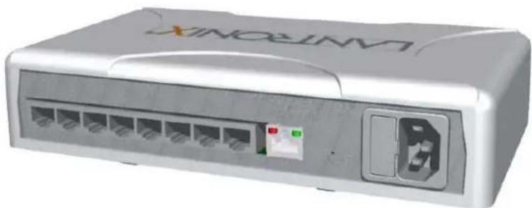
The EDS8PS (8 serial ports) and EDS16PS (16 serial ports) are compact desktop device servers that give you the ability to network-enable asynchronous RS-232 serial devices. They provide fully transparent RS-232 point-to-point connections without requiring modifications to existing software or hardware in your application.
Figure 2-1. EDS8PS Device Server
natural_image
3D rendering of a white LAN MartinX network switch with ports and ports (no visible text or symbols beyond branding)Features
Key features of the EDS8PS and EDS16PS include
Dual-purpose Ethernet terminal server and device server design.
8 (EDS8PS) or 16 (EDS16PS) serial ports with hardware handshaking signals.
RS-232 support.
An RJ45 Ethernet port.
8 MB Flash memory.
◆ 32 MB random access memory (RAM).
- Lantronix Evolution OS™.
A dedicated console port.
AES, SSH, or SSL secure data encryption.
Three convenient configuration methods (Web, command line, and XML).
◆ Print server functionality (LPR/LPD).
See Chapter 3: Installation of EDS8PS and EDS16PS for installation instructions.
EDS4100 Overview
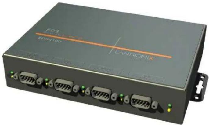
The EDS4100 is a compact device server that allows you to network-enable asynchronous RS-232 and RS-422/485 serial devices. It can deliver fully transparent RS-232/422 point-to-point connections and RS-485 multi-drop connections without requiring modifications to existing software or hardware in your application.
◆ Ports 1 through 4 support RS-232 devices.
◆ Ports 1 and 3 also support RS-422/485.
Note: RS-485 circuits support 32 full-load devices or 128 quarter-load devices. Each RS-485 port, however, counts as one device, leaving up to 31 full-load or 127 quarter-load devices that can be connected to the RS-485 circuit.
The EDS4100 device server supports the Power-over-Ethernet (PoE) standard. With PoE, power is supplied to the EDS over the Ethernet cable, by either an Ethernet switch or a midspan device. Being able to draw power through the Ethernet cable eliminates power supply and cord clutter. It also allows the EDS to be located in areas where power is not typically available.
Figure 2-2. EDS4100 4 Port Device Server
natural_image
Exterior view of a black electronic device labeled 'EDS 4100' with orange and green connectors, no readable text beyond branding.Features
The key features of the EDS4100 include
Dual-purpose Ethernet terminal server and device server design.
Four serial ports with hardware handshaking signals.
RS-232 and RS-422/485.
One RJ45 Ethernet port.
IEEE 802.3af standard for Power-over-Ethernet (PoE).
8 MB Flash memory.
◆ 32 MB Random Access Memory (RAM).
- Lantronix Evolution OS™.
AES, SSH, or SSL secure data encryption.
Three configuration methods (Web, command line, and XML).
◆ Print server functionality (LPR/LPD).
See Chapter 4: Installation of EDS4100 for installation instructions.
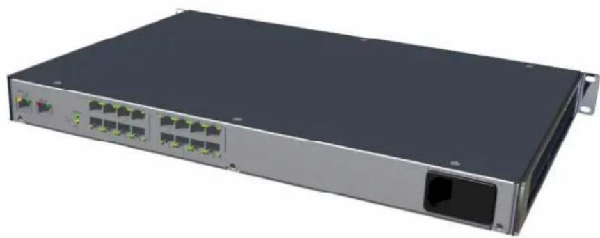
The EDS8PR (8 serial ports), EDS16PR (16 serial ports), and EDS32PR (32 serial ports) are compact easy-to-use, rack-mountable device servers that give you the ability to network-enable asynchronous RS-232 serial devices. They provide fully transparent RS-232 point-to-point connections without requiring modifications to existing software or hardware components in your application.
Figure 2-3. EDS16PR Device Server
natural_image
Front view of a network switch device with multiple Ethernet ports and a central port (no visible text or labels)Features
The key features of the EDS8PR, EDS16PR, and EDS32PR include
Dual-purpose Ethernet terminal server and device server design.
8 (EDS8PR), 16 (EDS16PR) or 32 (EDS32PR) serial ports with hardware handshaking signals.
RS-232 support.
One RJ45 Ethernet port.
8 MB Flash memory.
◆ 32 MB Random Access Memory (RAM).
- Lantronix Evolution OS™.
A dedicated console port.
AES, SSH, or SSL secure data encryption.
Three configuration methods (Web, command line, and XML).
◆ Print server functionality (LPR/LPD).
See Chapter 5: Installation of EDS8PR, EDS16PR, or EDS32PR on page 33, for installation instructions.
Protocols Supported
The EDS contains a full-featured TCP/IP stack. Supported protocols include:
ARP, IP, UDP, TCP, ICMP, BOOTP, DHCP, Auto IP, Telnet, DNS, FTP, TFTP, HTTP(S), SSH, SSL/TLS, SNMP, SMTP, RSS, PPP, and Syslog for network communications and management.
TCP, UDP, TCP/AES, UDP/AES, Telnet, SSH, and SSL/TLS for tunneling to the serial port.
◆ TFTP, FTP, and HTTP for file upload.
FTP and HTTP for firmware upgrade.
Evolution OS™
EDS incorporates The Lantronix Evolution OS™. Key features include
Built-in Web server for configuration and troubleshooting from Web-based browsers.
◆ CLI configurability.
SNMP management.
XML data transport and configurability.
◆ Really Simple Syndication (RSS) information feeds.
◆ Enterprise-grade security with SSL and SSH.
◆ Comprehensive troubleshooting tools.
Additional Features
Modem Emulation
In modem emulation mode, the EDS can replace dial-up modems. The unit accepts modem AT commands on the serial port, and establishes a network connection to the end device, leveraging network connections and bandwidth to eliminate dedicated modems and phone lines.
Web-Based Configuration and Troubleshooting
Built upon Internet-based standards, the EDS enables you to configure, manage, and troubleshoot through a browser-based interface accessible anytime from anywhere. All configuration and troubleshooting options are launched from a web interface. You can access all functions via a Web browser, for remote access. As a result, you decrease downtime (using the troubleshooting tools) and implement configuration changes (using the configuration tools).
Command-Line Interface (CLI)
Making the edge-to-enterprise vision a reality, the EDS with the Evolution OS ^™ uses industry-standard tools for configuration, communication, and control. For example,
the Evolution OS ^™ uses a Command Line Interface (CLI) whose syntax is very similar to that used by data center equipment such as routers and hubs.
SNMP Management
The EDS supports full SNMP management, making it ideal for applications where device management and monitoring are critical. These features allow networks with SNMP capabilities to correctly diagnose and monitor the EDS.
XML-Based Architecture and Device Control
XML is a fundamental building block for the future growth of M2M networks. The EDS supports XML-based configuration setup records that make device configuration transparent to users and administrators. The XML is easily editable with a standard text or XML editor.
Really Simple Syndication (RSS)
The EDS supports Really Simple Syndication (RSS), a rapidly emerging technology for streaming and managing on-line content. RSS feeds all the configuration changes that occur on the device. An RSS aggregator then reads (polls) the feed. More powerful than simple email alerts, RSS uses XML as an underlying Web page transport and adds intelligence to the networked device, while not taxing already overloaded email systems.
Enterprise-Grade Security
Evolution OS ^™ provides the EDS with the highest level of networking security possible. This ‘data center grade’ protection ensures that each device on the M2M network carries the same level of security as traditional IT networking equipment in the corporate data center.
By protecting the privacy of serial data transmitted across public networks, users can maintain their existing investment in serial technology, while taking advantage of the highest data-protection levels possible.
SSH and SSL can
◆ Verify the data received came from the proper source.
Validate that the data transferred from the source over the network has not changed when it arrives at its destination (shared secret and hashing).
◆ Encrypt data to protect it from prying eyes and nefarious individuals.
Provide the ability to run popular M2M protocols over a secure SSH or SSL connection.
In addition to keeping data safe and accessible, the EDS has robust defenses to hostile Internet attacks such as denial of service (DoS), which can be used to take down the network. Moreover, the EDS cannot be used to bring down other devices on the network.
You can use the EDS with the Lantronix Secure Com Port Redirector (SCPR) to encrypt COM port-based communications between PCs and virtually any electronic
device. SCPR is a Windows application that creates a secure communications path over a network between the computer and serial-based devices that are traditionally controlled via a COM port. With SCPR installed at each computer, computers that were formerly "hard-wired" by serial cabling for security purposes or to accommodate applications that only understood serial data can instead communicate over an Ethernet network or the Internet.
Terminal Server/Device Management
Remote offices can have routers, PBXs, servers and other networking equipment that require remote management from the corporate facility. The EDS easily attaches to the serial ports on a server, Private Branch Exchange (PBX), or other networking equipment to deliver central, remote monitoring and management capability.
With the menu system on the EDS, connections to the console ports of the attached devices as well as Ethernet hosts, such as Unix servers or another EDS, can easily be picked from a user-defined menu. This allows console ports across multiple devices to be accessed from one EDS.
Troubleshooting Capabilities
The EDS offers a comprehensive diagnostic toolset that lets you troubleshoot problems quickly and easily. Available from the Web Manager, CLI, and XML interfaces, the diagnostic tools let you
View critical hardware, memory, MIB-II, buffer pool, and IP socket information.
◆ Perform ping and trace route operations.
◆ Conduct forward or backup DNS lookup operations.
View all processes currently running on the EDS, including CPU utilization and total stack space available.
Configuration Methods
After installation, the EDS requires configuration. For the unit to operate correctly, it must have a unique IP address on the network. There are three basic methods for logging into the EDS and assigning IP addresses and other configurable settings:
DeviceInstaller: Configure the IP address and related settings and view current settings on the EDS using a Graphical User Interface (GUI) on a PC attached to a network. (See 6: Using DeviceInstaller on page 38.)
Web Manager: Through a web browser, configure the EDS settings using the Lantronix Web Manager. (See 7: Configuration Using Web Manager on page 41.)
Command Mode: There are two methods for accessing Command Mode (CLI): making a Telnet connection or connecting a terminal (or a PC running a terminal emulation program) to the unit serial port. (See the EDS Command Reference Guide for instructions and available commands.)
XML: The EDS supports XML-based configuration and setup records that make device configuration transparent to users and administrators. XML is easily editable with a standard text or XML editor. (See the EDS Command Reference Guide for instructions and commands.)
Addresses and Port Numbers
Hardware Address
The hardware address is also referred to as the Ethernet address or MAC address. The first three bytes of the Ethernet address are fixed and read 00-20-4A, identifying the unit as a Lantronix product. The fourth, fifth, and sixth bytes are unique numbers assigned to each unit.
Figure 2-4. Sample Hardware Address
00-20-4A-14-01-18
or
00:20:4A:14:01:18
IP Address
Every device connected to an IP network must have a unique IP address. This address references the specific unit.
Port Numbers
Every TCP connection and every UDP datagram is defined by a destination and source IP address, and a destination and source port number. For example, a Telnet server commonly uses port number 23.
The default server port numbers running on the EDS include
TCP Port 22: SSH Server (Command Mode configuration).
TCP Port 23: Telnet Server (Command Mode configuration).
TCP Port 80: HTTP (Web Manager configuration).
TCP Port 443: HTTPS (Web Manager configuration).
◆ UDP Port 161: SNMP.
TCP Port 21: FTP.
◆ UDP Port 69: TFTP.
◆ UDP Port 514: Syslog.
TCP Port 515: LPD.
◆ UDP Port 30718: LDP (Lantronix Discovery Protocol) port.
TCP/UDP Port 10001: Tunnel 1.
TCP/UDP Port 10002: Tunnel 2.
Product Information Label
The product information label on the bottom of the device contains the following information:
Bar code
Product ID (name)
Product Revision
Part number
◆ Hardware Address (MAC Address)
3: Installation of EDS8PS and EDS16PS
This chapter describes how to install the EDS8PS and EDS16PS device servers.
Package Contents
Your EDS package includes the following items:
One EDS device server (EDS8PS or EDS16PS)
One RJ45-to-DB9F serial cable
One product CD that includes this User Guide, the Command Reference, and the Quick Start guide.
A printed Quick Start guide
Your package may also include a power supply.
User-Supplied Items
To complete your EDS8/16PS installation, you need the following items:
RS-232 serial devices that require network connectivity. Each EDS8/16/32PR serial port supports a directly connected RS-232 serial device.
A serial cable for each serial device to be connected to the EDS8/16/32PR. All devices attached to the device ports support the RS-232C (EIA-232) standard. Category 5 cabling with RJ45 connections is used for the device port connections.
Note: To connect an EDS8/16PS serial port to a DTE device, you need a DTE cable, such as the one supplied in your EDS8/16PS package, or an RJ45 patch cable and DTE adapter. To connect the EDS8/16PS serial port to a DCE device, you need a DCE (modem) cable, or an RJ45 patch cable and DTE adapter. For a list of the Lantronix cables and adapters you can use with the EDS8/16PS, see Appendix C: Lantronix Cables and Adapters.
An available connection to your Ethernet network and an Ethernet cable.
A working power outlet if the unit will be powered from an AC outlet.
Identifying Hardware Components
Figure 3-1 shows the front of the EDS8PS.
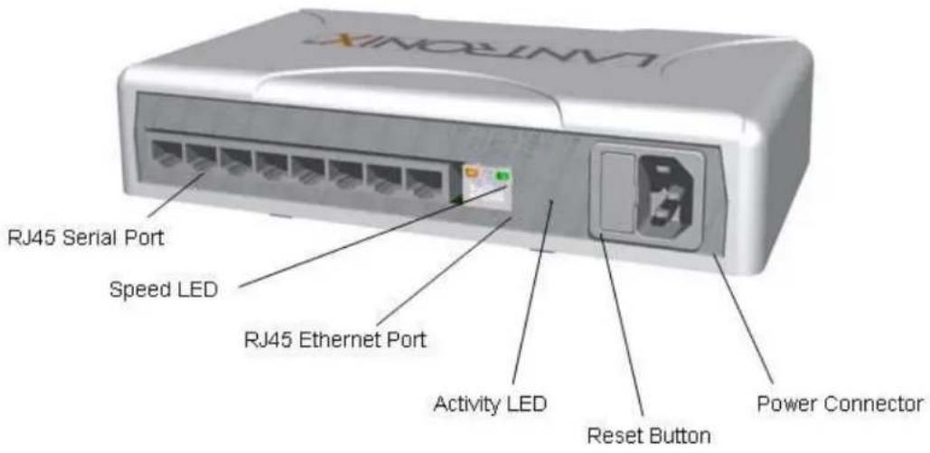
Figure 3-2 shows the back of the EDS8PS.
Figure 3-1. Front View of the EDS8PS
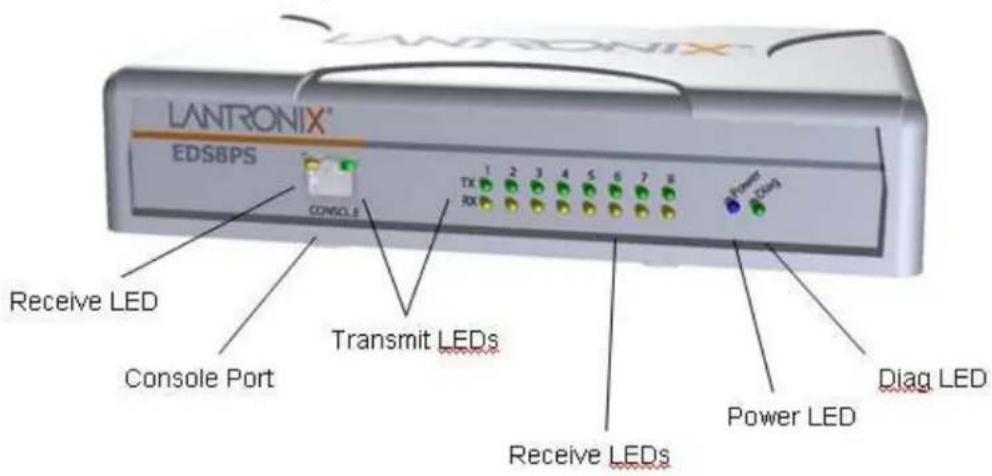
Figure 3-2. Back View of the EDS8PS
The product information label on the bottom contains the following information:
Bar code
Serial number
Product ID (name)
Product description
◆ Hardware address (also referred to as Ethernet or MAC address)
◆ Agency certifications
Serial Ports
The EDS8PS has 8 serial ports and the EDS16PS has 16 serial ports on the back panel. All are configured as DTE and support up to 230,400 baud.
Console Port
The front panel of the EDS8/16/32PR provides an RJ45 Console port. It is an extra serial port configured as DTE and supports baud rates up to 230,400 baud.
Figure 3-3. RJ45 Serial Port
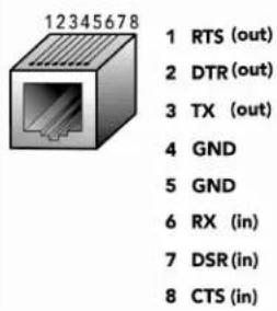
Ethernet Port
The back panel of the EDS8/16PS provides a network interface via the rightmost RJ45 port. This port can connect to an Ethernet (10 Mbps) or Fast Ethernet (100 Mbps) network. The Speed LED on the back of the EDS8/16PS shows the connection of the attached Ethernet network. The EDS8/16PS can be configured to operate at a fixed Ethernet speed and duplex mode (half- or full-duplex) or to auto-negotiate the connection to the Ethernet network.
LEDs
Light-emitting diodes (LEDs) on the front panel show status information.
Each serial port plus the console port have a Transmit and a Receive LED. The Ethernet port has Speed, Activity, Power, and Status LEDs.
The table below describes the LEDs on the front of the EDSPS.
Front Panel LEDs
| LED Description | |
| Transmit(green) | Blinking = EDS is transmitting data on the serial port. |
| Receive (yellow) | Blinking = EDS is receiving data on the serial port. |
| Power (blue) | On = EDS is receiving power. |
| Diag (green) | Fast blink = initial startup (loading OS).Slow blink (once per second) = operating system startup.On = unit has finished booting. |
LED Description
Speed (yellow)
On = EDS is connected to a 100 Mbps Fast Ethernet network.
Off = EDS is connected to a 10 Mbps Ethernet network.
Activity (green)
Blink = EDS is sending data to or receiving data from the Ethernet network.
Reset Button
The reset button is on the rear of the device to the right of the Ethernet port, accessible through a hole in the case. You can use it to reboot the unit or to reload factory defaults.
Reboot the device:
- Press and hold the reset button for about 3 seconds. The status LED blinks quickly.
- When the fast blinks stop, release the button. When the unit reboots, the status LED changes from a fast blink to a solid ON.
Restore factory defaults:
- Press and hold the reset button for about 11 seconds. The LED blinks quickly for about 3 seconds, then comes on for about 5 seconds, then blinks slowly for about 2 seconds.
- When the slow blinks stop, release the button.
Installing the EDS8/16PS
Finding a Suitable Location
You can install the EDS8/16PS either in a shelf or as a desktop unit.
If using AC power, avoid outlets controlled by a wall switch.
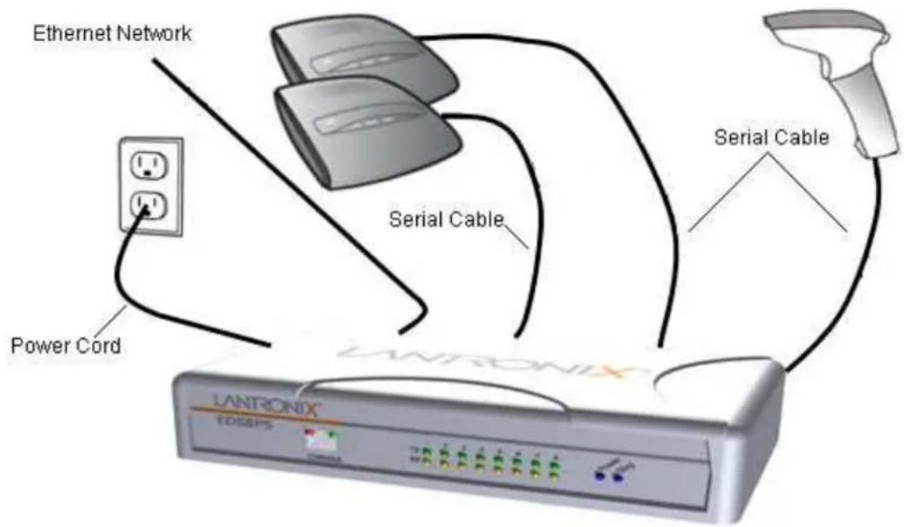
Connecting the EDS8/16PS
All EDS serial ports support RS-232 devices.
Connect the EDS8/16PS to one or more serial devices.
- Power off the serial devices.
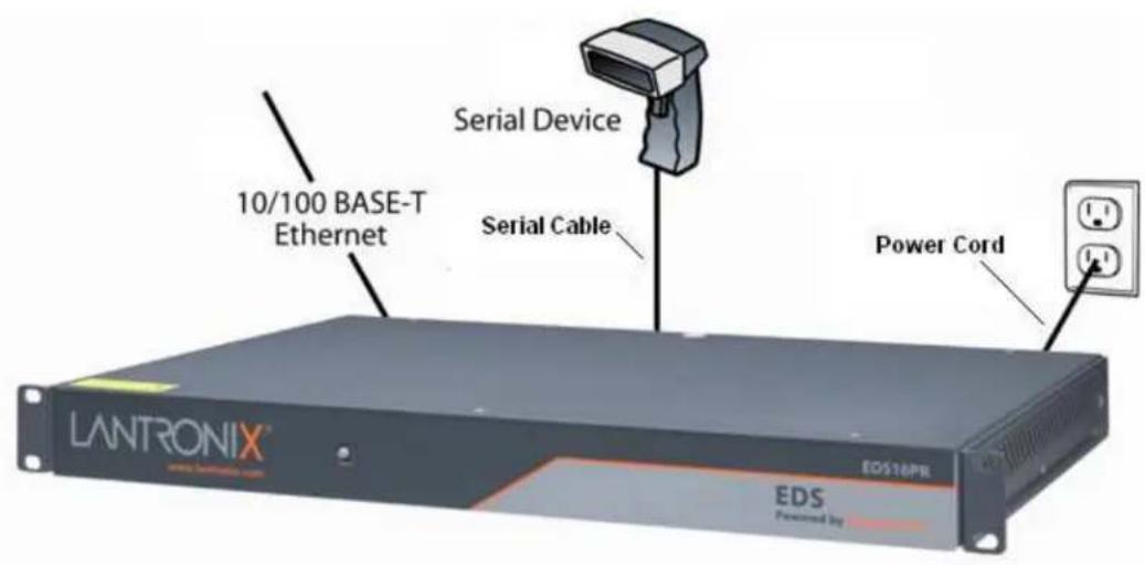
- Attach a CAT 5 serial cable between the EDS8/16PS and your serial device. See Appendix C: Lantronix Cables and Adapters, for a list of cables and adapters you can use.
-
Connect an Ethernet cable between the EDS8/16PS Ethernet port and your Ethernet network.
-
Insert the power cord into the back of the EDS8/16PS. Plug the other end into an AC wall outlet.
-
Power up the serial devices.
Figure 3-4. Example of EDS8/16PS Connections
4: Installation of EDS4100
This chapter describes how to install the EDS4100 device server. See EDS4100 Overview on page 14 for connection and protocol specifications.
Package Contents
Your EDS4100 package includes the following items:
One EDS4100 device server.
One DB9F-to-DB9Fnull modem cable.
A CD that includes this User Guide, the Command Reference Guide, and the Quick Start Guide.
A printed Quick Start Guide.
Your package may also include a power supply.
User-Supplied Items
To complete your EDS4100 installation, you need the following items:
RS-232 and/or RS-422/485 serial devices that require network connectivity:
A serial cable for each serial device. One end of the cable must have a female DB9 connector for the EDS4100 serial port.
To connect an EDS4100 serial port to another DTE device, you will need a null modem cable, such as the one supplied in your EDS4100 package.
To connect the EDS4100 serial port to a DCE device, you will need a straight-through (modem) cable.
An available connection to your Ethernet network and an Ethernet cable.
A working power outlet if the unit will be powered from an AC outlet.
Identifying Hardware Components
The following two figures show the front and back of the EDS4100.
Figure 4-1. Front View of the EDS4100
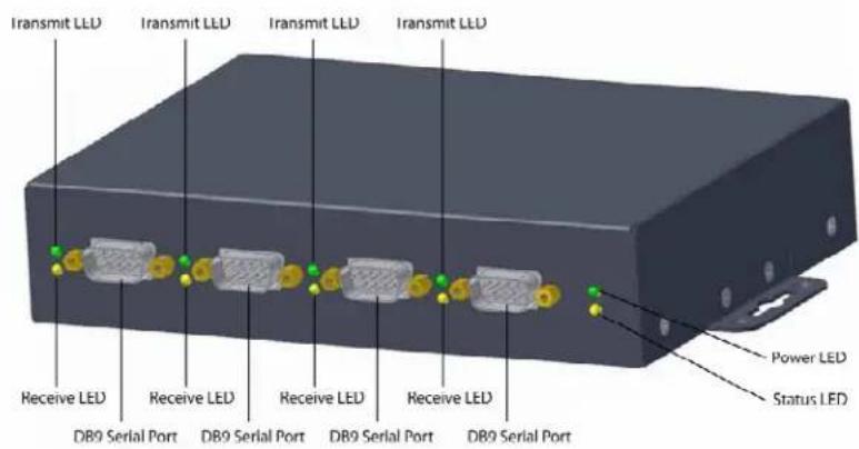
Figure 4-2. Back View of the EDS4100
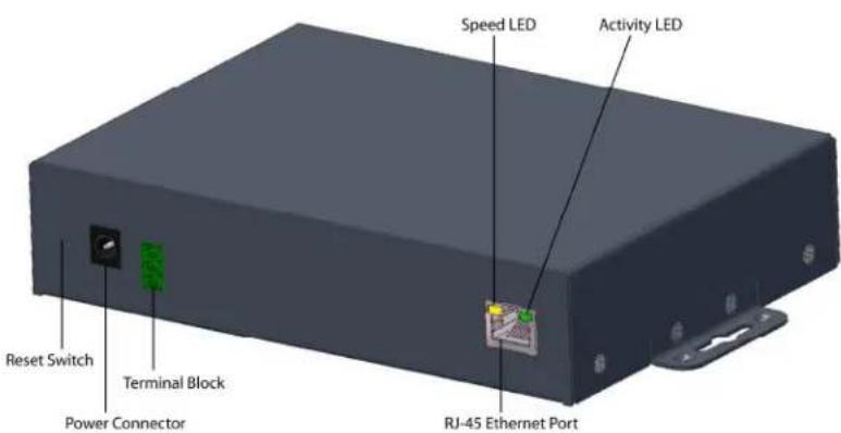
The bottom of the EDS4100 (not shown) has a product information label. This label contains the following information:
Bar code
Serial number
Product ID (name)
Product description
◆ Hardware address (also referred to as Ethernet or MAC address)
◆ Agency certifications
Serial Ports
The front of the EDS4100 has four male DB9 serial ports. These ports allow you to connect up to four standard serial devices:
All four serial ports support RS-232 devices. See Figure 4-3 for pin assignments.
Serial ports 1 and 3 also support RS-422 and RS-485 serial devices. See Figure 4-4 for pin assignments.
All four serial ports are configured as DTE.
◆ Ports 1 & 3 support up to 921600
◆ Ports 2 & 4 support up to 230400
Figure 4-3. RS-232 Serial Port Pins (Serial Ports 1, 2, 3, 4)
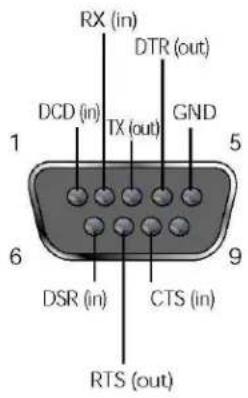
Figure 4-4. RS-422/RS-485 Serial Port Pins
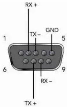
RS-422/485 4-wire Pin Assignments (Serial Ports 1 and 3)
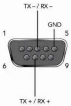
RS-485 2-wire Pin Assignments (Serial Ports 1 and 3)
Note: Multi-drop connections are supported in 2-wire mode only.
Ethernet Port
The back panel of the EDS4100 provides an RJ45 Ethernet port. This port can connect to an Ethernet (10 Mbps) or Fast Ethernet (100 Mbps) network. The Speed
LED on the back of the EDS4100 shows the connection of the attached Ethernet network. The EDS4100 can be configured to operate at a fixed Ethernet speed and duplex mode (half- or full-duplex) or auto-negotiate the connection to the Ethernet network.
Terminal Block Connector
The back of the EDS4100 has a socket for a terminal block screw connector (not included) for attaching to an appropriate power source, such as those used in automation and manufacturing industries. The terminal block connector supports a power range from 42 VDC to 56 VDC. It can be used with the EDS4100's barrel power connector and PoE capabilities as a redundant power source to the unit. Vendors who do supply this connector can be found by doing a web search for part 'Phoenix 1803581 MC 1,5/3-ST-3,81'.
Figure 4-5. Terminal Block Connector Pin Assignments
| Pin Signal |
| Top V+ |
| Middle V- |
| Bottom Ground |
LEDs
Light-emitting diodes (LEDs) on the front and back panels show status information.
- Back panel. Each serial port has a Transmit and a Receive LED. The Ethernet connector has Speed and Activity LEDs. In addition, the back panel has a Power LED and a Status LED.
Front panel. The front panel has a green Power LED.
The table below describes the LEDs on the back of the EDS4100.
Figure 4-6. Back Panel LEDs
| LED Description | |
| Transmit (green) | Blinking = EDS is transmitting data on the serial port. |
| Receive (yellow) | Blinking = EDS is receiving data on the serial port. |
| Power (green) | On = EDS is receiving power. |
| Status (yellow) | Fast blink = initial startup (loading OS).Slow blink (once per second) = operating system startup.On = unit has finished booting. |
| (yellow) | On = EDS is connected to a 100 Mbps Fast Ethernet network. Speed |
| Off = EDS is connected to a 10 Mbps Ethernet network. | |
| Activity Blink = EDS is sending data to or receiving data from the Ethernet | |
LED Description
(green) network.
Reset Button
The reset button is on the back of the EDS4100, to the left of the power connector. Pressing this button reboots the EDS4100 and terminates all data activity occurring on the serial and Ethernet ports.
Physically Installing the EDS4100
Finding a Suitable Location
Place the EDS4100 on a flat horizontal or vertical surface. The EDS4100 comes with mounting brackets installed for vertically mounting the unit, for example, on a wall.
If using AC power, avoid outlets controlled by a wall switch.
Connecting the EDS4100
Observe the following guidelines when attaching serial devices:
All four EDS4100 serial ports support RS-232 devices.
Alternatively, ports 1 and 3 support RS-422/485 devices.
To connect an EDS4100 serial port to another DTE device, use a null modem cable.
To connect the EDS4100 serial port to a DCE device, use a straight-through (modem) cable.
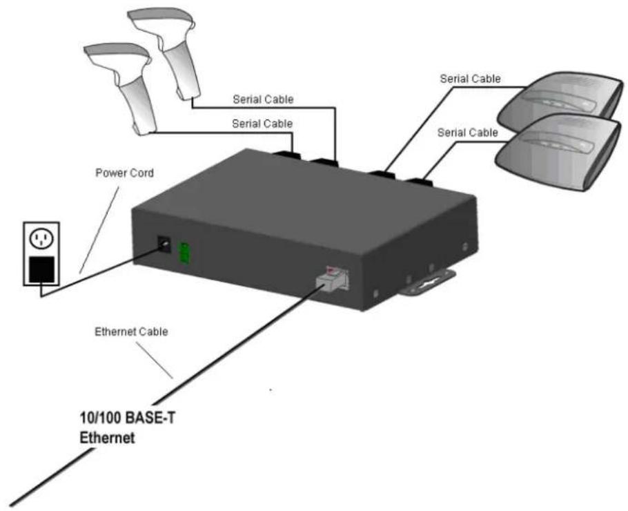
Connect the EDS4100 to one or more serial devices.
- Power off the serial devices.
- Attach a serial cable between the EDS4100 and each serial device.
- Connect an Ethernet cable between the EDS4100 Ethernet port and your Ethernet network.
- Power-up the EDS4100. Use one or more of the following methods.
These power-up methods can be used in combination to provide redundant backup power to the unit.
- PoE: Power is supplied over the Ethernet cable by an Ethernet switch or a mid-span device.
- Barrel power connector: The barrel power connector supports a power range of 9 to 30 VDC. Insert the round end of the supplied power cord into the barrel power connector on the back of the EDS4100. Plug the other end into an AC wall outlet.
- Terminal block connector: The terminal block connector supports a power range of 42 VDC to 56 VDC. Attach the power source to the terminal block connector on the back of the EDS4100.
As soon as you plug it in, the EDS4100 powers up automatically, the self-test begins, and Evolution OS ^TM starts.
- Power up the serial devices.
Figure 4-7. Example of EDS4100 Connections
5: Installation of EDS8PR, EDS16PR, or EDS32PR
This chapter describes installing the EDS8PR, EDS16PR and EDS32PR device servers. See EDS8PR, EDS16PR, and EDS32PR Overview on page 16, for overview information.
Package Contents
Your EDS package includes the following items:
One EDS device server (EDS8PR, EDS16PR or EDS32PR).
One RJ45-to-DB9F serial cable.
A CD that includes this User Guide, the Command Reference Guide, and the Quick Start Guide.
A printed Quick Start guide.
- Your package may also include a power supply.
User-Supplied Items
To complete your EDS8/16/32PR installation, you need the following items:
RS-232 serial devices that require network connectivity. Each EDS8/16/32PR serial port supports a directly connected RS-232 serial device.
A serial cable for each serial device. All devices attached to the EDS device ports must support the RS-232C (EIA-232) standard. Category 5 cabling with RJ45 connections is used for the device port connections.
Note: To connect an EDS8/16/32PR serial port to a DTE device, you need a DTE cable, such as the one supplied in your EDS8/16/32PR package, or an RJ45 patch cable and DTE adapter. To connect the EDS8/16/32PR serial port to a DCE device, you need a DCE (modem) cable, or an RJ45 patch cable and DTE adapter.
For a list of the Lantronix cables and adapters you can use with the EDS8/16/32PR, see Appendix C: Lantronix Cables and Adapters.
An available connection to your Ethernet network and an Ethernet cable.
A working power outlet if the unit will be powered from an AC outlet.
Identifying Hardware Components
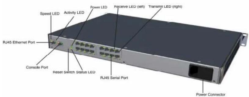
The following two figures show the components on the front and back of the EDS16PR.
Figure 5-1. Front View of the EDS16PR
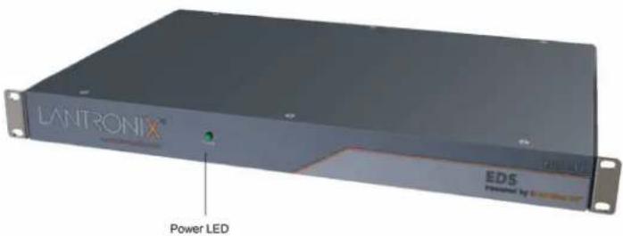
Figure 5-2. Back View of the EDS16PR
Product Label
A product information label on the bottom contains the following information:
Bar code
Serial number
Product ID (name)
Product description
◆ Hardware address (also referred to as Ethernet or MAC address)
◆ Agency certifications
Serial Ports
All EDS serial ports are configured as DTE and support up to 230,400 baud.
The EDS8PR has 8 serial ports.
The EDS16PR has 16 serial ports.
The EDS32PR has 32 serial ports.
Console Port
The front panel has an RJ45 Console port. It is an extra serial port configured as DTE and supports up to 230,400 baud.
Figure 5-3. RJ45 Serial Port
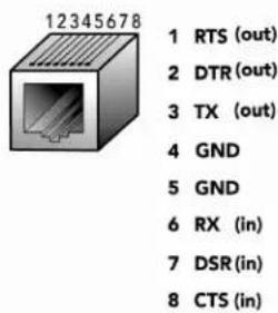
Ethernet Port
The back panel has an RJ45 Ethernet port. This port can connect to an Ethernet (10 Mbps) or Fast Ethernet (100 Mbps) network.
The Speed LED on the back panel shows the connection speed of the connected Ethernet network.
You can configure the EDS to operate at a fixed Ethernet speed and duplex mode (half- or full-duplex) or auto-negotiate the connection to the Ethernet network.
LEDs
Light-emitting diodes (LEDs) on the front and back panels show status information.
Front panel. The front panel has a green Power LED.
Back panel. Each serial port has a Transmit and a Receive LED. The Ethernet connector has Speed and Activity LEDs. There is also a Power LED and a Status LED.
The table below describes the LEDs on the back of the EDS.
Back Panel LEDs
| LED Description |
| Transmit (green) Blinking = EDS is transmitting data on the serial port. |
| Receive (yellow) Blinking = EDS is receiving data on the serial port. |
| Power (green) On = EDS is receiving power. |
LED Description
Status (yellow) Fast blink = initial startup (loading OS).
Slow blink (once per second) = operating system startup.
On = unit has finished booting.
On = EDS is connected to a 100 Mbps Fast Ethernet network. Speed (yellow)
Off = EDS is connected to a 10 Mbps Ethernet network.
Activity (green) Blink = EDS is sending data to or receiving data from the Ethernet network.
Reset Button
The reset button is on the back of the EDS, to the left of the power connector.
Pressing this button for 2-to-3 seconds reboots the EDS8/16/32PR and terminates all data activity occurring on the serial and Ethernet ports.
Installing the EDS8/16/32PR
Finding a Suitable Location
You can install the EDS8/16/32PR either in an EIA-standard 19-inch rack (1U tall) or as a desktop unit. If using AC power, avoid outlets controlled by a wall switch.
Connecting the EDS8/16/32PR
- Power off the serial devices that will be connected to the EDS8/16/32PR.
- Attach a CAT 5 serial cable between the EDS8/16/32PR and your serial device. For a list of cables and adapters you can use with the EDS8/16/32PR, see Appendix C: Lantronix Cables and Adapters.
- Connect an Ethernet cable between the EDS8/16/32PR Ethernet port and your Ethernet network.
- Insert the power cord into the back of the EDS8/16/32PR. Plug the other end into an AC wall outlet. After power-up, the self-test begins.
- Power up the serial devices.
Figure 5-4. Example of EDS16PR Connections
6: Using DeviceInstaller
This chapter covers the steps for locating an EDS unit and viewing its properties and device details.
For instructions on using DeviceInstaller to configure the IP address and related settings or for more advanced features, see the Device Installer online Help.
Accessing an EDS using Devicelnstaller
Note: Write down the MAC address from the product label. You will need it to locate the EDS using Devicelnstaller.
Follow the instructions on the product CD to install and run Devicelnstaller.
- Click Start→All Programs→Lantronix→DeviceInstaller→DeviceInstaller.
- When DeviceInstaller starts, it will perform a network device search. To perform another search, click the "Search" button.
- Expand the EDS folder by clicking the + symbol next to the EDS folder icon. The list of available Lantronix EDS devices appears.
- Select the EDS unit by expanding its entry and clicking on its hardware (MAC) address to view its configuration.
- On the right page, click the Device Details tab. The current EDS configuration appears. This is only a subset of the full configuration; the full configuration may be accessed via Web Manager, CLI, or XML.
Device Details Summary
Note: The settings in this table are Display Only unless otherwise noted.
| Current Settings Description | |
| Name Name identifying the EDS. | |
| Group Configurable field. Enter a group to categorize the EDS. Double-click the field, type in the value, and press Enter to complete. This group name is local to this PC and is not visible on other PCs or laptops using DeviceInstaller. | |
| Comments Configurable field. Enter comments for the EDS.Double-click the field, type in the value, and press Enter to complete. This description or comment is local to this PC and is not visible on other PCs or laptops using DeviceInstaller. | |
| Device Family Shows the EDS device family type as “EDS”. | |
| Type Shows the device type as “EDS”. | |
| ID Shows the EDS ID embedded within the unit. | |
| Hardware Address Shows the EDS hardware (MAC) address. | |
| Firmware Version Shows the firmware currently installed on the EDS. | |
| Extended Firmware Version | Provides additional information on the firmware version. |
| Online Status Shows the EDS status as Online, Offline, Unreachable (the EDS is on a different subnet), or Busy (the EDS is currently performing a task). | |
| IP Address Shows the EDS current IP address. To change the IP address, click the Assign IP button on the Devicelnstaller menu bar. | |
| IP Address was Obtained | Appears “Dynamically” if the EDS automatically received an IP address (e.g., from DHCP). Appears “Statically” if the IP address was configured manually.If the IP address was assigned dynamically, the following fields appear:Obtain via DHCP with values of True or False.Obtain via BOOTP with values of True or False. |
| Subnet Mask Shows the subnet mask specifying the network segment on which the EDS resides. | |
Current Settings Description
| Gateway Shows the IP address of the router of this network.There is no default. | |
| Number of Ports Shows the number of serial ports on this MarchPort AR. | |
| Supports Configurable Pins | Shows False, indicating configurable pins are available on the EDS. |
| Supports Email Triggers | Shows True, indicating email triggers are available on the EDS. |
| Telnet Enabled Indicates whether Telnet is enabled on this EDS. | |
| Telnet Port Shows the EDS port for Telnet sessions. | |
| Web Enabled Indicates whether Web Manager access is enabled on this EDS. | |
| Web Port Shows the EDS port for Web Manager configuration. | |
| Maximum Baud Rate Supported | Shows the EDS maximum baud rate. |
| Firmware Upgradeable | Shows True, indicating the EDS firmware is upgradeable as newer versions become available. |
7: Configuration Using Web Manager
This chapter describes how to configure the EDS using Web Manager, the Lantronix browser-based configuration tool.
The unit configuration is stored in nonvolatile memory and is retained without power.
All changes take effect immediately, unless otherwise noted.
Accessing Web Manager through a Web Browser
Access the Web Manager:
One Step Select the Web Configuration tab on the DeviceInstaller window.
—Or—
-
Open a standard web browser (such as Netscape Navigator 6.x and above, Internet Explorer 5.5. and above, Mozilla Suite, Mozilla Firefox, Opera, Safari, or Chrome).
-
Enter the IP address of the EDS.
-
Enter your user name and password. The factory-default user name and password are "admin" and "PASS".
-
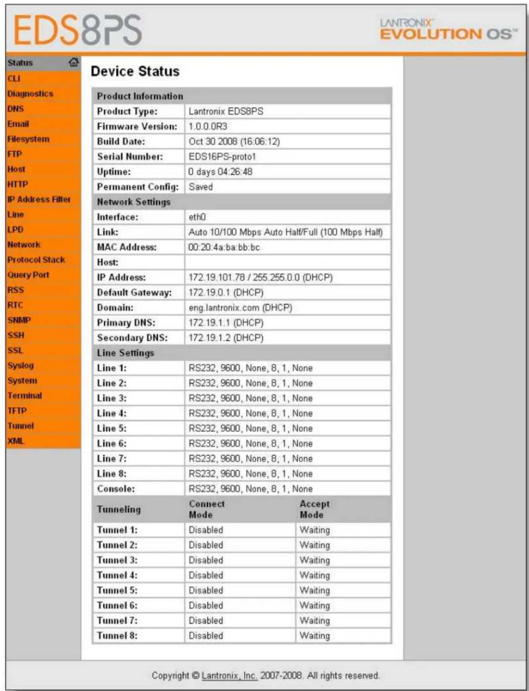
The Web Manager home page (the Device Status page) appears. It shows the EDS configuration and product information.
Figure 7-1. The EDS Web Manager Status Home Page
Web Manager Page Components
Use Figure 7-2 to orient yourself to the areas of the EDS Web Manager page.
Figure 7-2. Components of the Web Manager Page
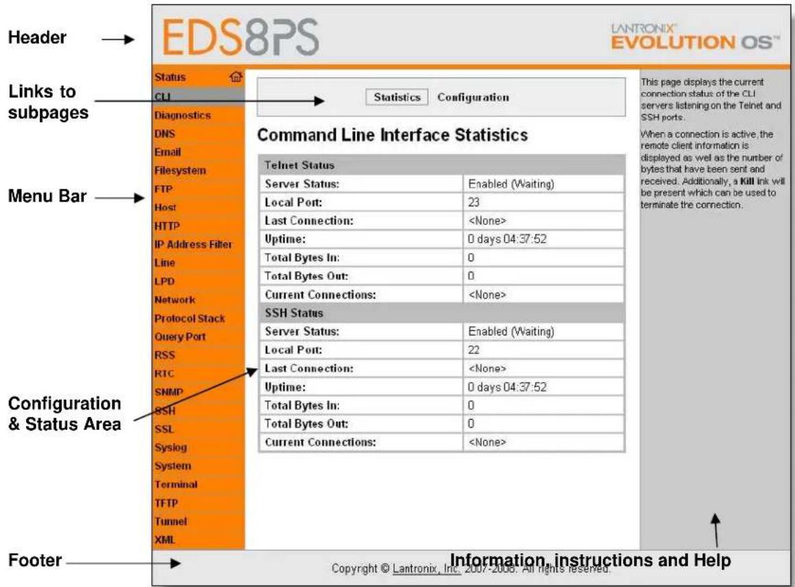
The Orange Menu Bar always appears at the left of the page. It lists the names of the pages available in the Web Manager. To bring up a page, click it in the menu bar.
The white area of the page has from one to three sections:
At the top, many pages, such as the one in the example above, enable you to link to sub pages. On some pages, you must also select the item you are configuring, such as a line or a tunnel.
In the middle section, you can select or enter new configuration settings. After you change settings, click Submit to apply the changes. Some settings require a reboot of the EDS before the settings take effect. Those settings are identified in the appropriate sections in this chapter.
The bottom section usually shows the current configuration. In some cases, you can reset or clear a configuration setting.
The Instructions, Information, and Help area shows information or instructions associated with the page.
The Footer appears at the bottom of the page. It contains copyright information and a link to the Lantronix home page.
Navigating the Web Manager
The Web Manager provides an intuitive point-and-click interface.
A menu bar at the left side of each page provides links you can click to navigate from one page to another.
Some pages are read-only, while others let you change configuration settings.
Summary of Web Manager Pages
| Web Menu Link | Description | See Page |
| Status | Shows product information and network, line, and tunneling settings. | 46 |
| CLI | Shows Command Line Interface (CLI) statistics and lets you change the current CLI configuration settings. | 124 |
| Diagnostics | Lets you perform various diagnostic procedures. 110 | |
| DNS | Shows the current configuration of the DNS subsystem and the DNS cache. | 78 |
| Shows email statistics and lets you clear the email log, configure email settings, and send an email. | 121 | |
| Filesystem | Shows file system statistics and lets you browse the file system to view a file, create a file or directory, upload files using HTTP, copy a file, move a file, or perform TFTP actions. | 103 |
| FTP | Shows statistics and lets you change the current configuration for the File Transfer Protocol (FTP) server. | 80 |
| Host | Lets you view and change settings for a host on the network. | 75 |
| HTTP | Shows HyperText Transfer Protocol (HTTP) statistics and lets you change the current configuration and authentication settings. | 83 |
| IP Address Filter | Lets you specify all the IP addresses and subnets that are allowed to send data to this device. | 109 |
| Line | Shows statistics and lets you change the current configuration and Command mode settings of a serial line. | 52 |
| LPD | Shows LPD (Line Printer Daemon) Queue statistics and lets you configure the LPD and print a test page. | 90 |
| Network | Shows status and lets you configure the network interface. | 47 |
| Protocol Stack | Lets you perform lower level network stack-specific activities. | 106 |
| Query Port | Lets you change configuration settings for the query port. | 110 |
| RSS | Lets you change current Really Simple Syndication(RSS) settings. | 89 |
| SNMP | Lets you change the current Simple Network Management Protocol (SNMP) configuration settings. | 78 |
| SSH | Lets you change the configuration settings for SSH server host keys, SSH server authorized users, SSH client known hosts, and SSH client users. | 93 |
| SSL | Lets you upload an existing certificate or create a new self-signed certificate. | 99 |
| Syslog | Lets you specify the severity of events to log and the server and ports to which the syslog should be sent. | 82 |
| System | Lets you reboot the EDS, restore factory defaults, upload new firmware, and change the EDS long and short names. | 120 |
| Terminal | Lets you change current settings for a terminal. 72 | |
| TFTP | Shows statistics and lets you change the current configuration for the Trivial File Transfer Protocol (TFTP) server. | 81 |
| Tunnel Settings | Lets you change the configuration settings for a tunnel. | 57 |
| XML | Lets you export XML configuration and status records, and import XML configuration records. | 126 |
Device Status Page
The Device Status page is the first page that appears when you log into the Web Manager. It also appears when you click the Status link in the menu bar.
This read-only page shows EDS product information, network settings, line settings, and tunneling settings.
Figure 7-3. Device Status
| Device Information | ||
| Product Type: | Lantronix EDS8PS | |
| Firmware Version: | 1.0.0.0R3 | |
| Build Date: | Oct 30 2008 (16:06:12) | |
| Serial Number: | EDS16PS-proto1 | |
| Uptime: | 0 days 23:26:28 | |
| Permanent Config: | Saved | |
| Network Settings | ||
| Interface: | eth0 | |
| Link: | Auto 10/100 Mbps Auto Half/Full (100 Mbps Half) | |
| MAC Address: | 00:20:4a:ba:bb:bc | |
| Host: | ||
| IP Address: | 172.19.101.78 / 255.255.0.0 (DHCP) | |
| Default Gateway: | 172.19.0.1 (DHCP) | |
| Domain: | eng.lantronix.com (DHCP) | |
| Primary DNS: | 172.19.1.1 (DHCP) | |
| Secondary DNS: | 172.19.1.2 (DHCP) | |
| Line Settings | ||
| Line 1: | RS232, 9600, None, 8, 1, None | |
| Line 2: | RS232, 9600, None, 8, 1, None | |
| Line 3: | RS232, 9600, None, 8, 1, None | |
| Line 4: | RS232, 9600, None, 8, 1, None | |
| Line 5: | RS232, 9600, None, 8, 1, None | |
| Line 6: | RS232, 9600, None, 8, 1, None | |
| Line 7: | RS232, 9600, None, 8, 1, None | |
| Line 8: | RS232, 9600, None, 8, 1, None | |
| Console: | RS232, 9600, None, 8, 1, None | |
| Tunneling | Connect Mode | Accept Mode |
| Tunnel 1: | Disabled | Waiting |
| Tunnel 2: | Disabled | Waiting |
| Tunnel 3: | Disabled | Waiting |
| Tunnel 4: | Disabled | Waiting |
8: Network Settings
The Network Settings pages show the status of the Ethernet link and let you configure it on the EDS device.
Network Settings
Network 1 (eth0) Interface Status
This page shows the status of the Ethernet network interface.
View the network interface status:
- Click Network.
- Click Network 1, Interface, and Status. (Default) The Network 1 (eth0) Interface Status page appears.
Figure 8-1. Network 1 (eth0) Interface Status
flowchart
graph TD
    A["Network 1"] --> B["Interface Link"]
    B --> C["Status Configuration"]
Network 1 (eth0) Interface Status
| Current | After Reboot | |
| BOOTP Client: | Off | Off |
| DHCP Client: | On [Renew] | On |
| IP Address: | 172.19.101.78 (DHCP) | |
| Network Mask: | 255.255.0.0 (DHCP) | |
| Default Gateway: | 172.19.0.1 (DHCP) | |
| Hostname: | ||
| Domain: | eng.lantronix.com (DHCP) | |
| DNS Suffix Search List: | eng.lantronix.com. int.lantronix.com. lantronix.com. | |
| DHCP Client ID: |
This page is used to view the status of the Network interface on the device.
There are two columns displayed. The first column shows the current operational settings. The second column shows the expected settings after the device is rebooted.
If both BOOTP and DHCP are turned on, DHCP will run, but not BOOTP.
When BOOTP or DHCP fails to discover an IP Address, a new address will automatically be generated using AutolP. This address will be within the 169.254.x.x space.
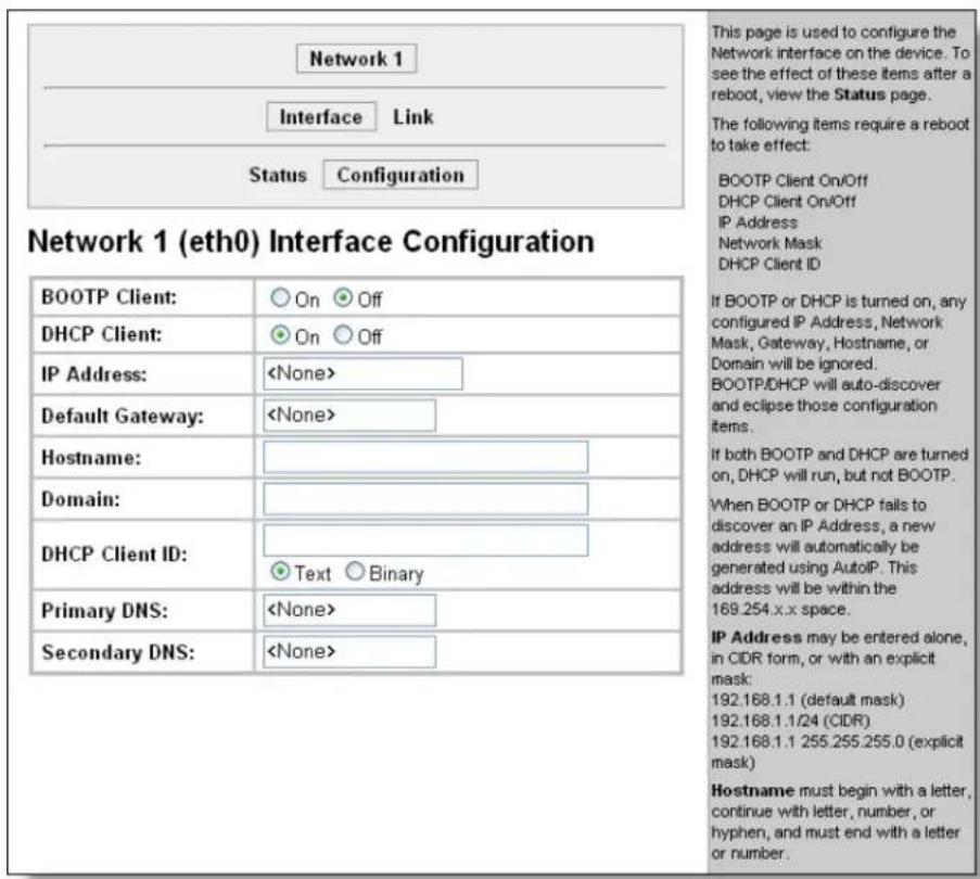
Network 1 (eth0) Interface Configuration
This page shows the configuration settings for the Ethernet connection and lets you change these settings.
View and configure network interface settings:
1. Click Network 1, Interface, and Configuration.
The Network 1 (eth0) Interface Configuration page appears.
Figure 8-2. Network 1 (eth0) Interface Configuration
2. Enter or modify the following settings:
| Network 1InterfaceConfigurationPage Settings | Description |
| BOOTP ClientDHCP Client | Select On or Off. At boot up the EDS will attempt to obtain an IP address from a BOOTP server.Notes:Overrides the configured IP address, network mask, gateway, hostname, and domain.When DHCP is On, the system automatically uses DHCP, regardless of whether BOOTP Client is On.Select On or Off. At boot up the EDS will attempt to lease an IP address from a DHCP server and maintain the lease at regular intervals.Note:Overrides BOOTP, the configured IP address, network mask, gateway, hostname, and domain. |
| IP Address | Enter the EDS static IP address.You may enter it alone, in CIDR format, or with an explicit mask.The IP address consists of four octets separated by a period and is used if BOOTP and DHCP are both set to Off. Changing this value requires you to reboot the EDS.Note:When DHCP is enabled, the EDS tries to obtain an IP address from DHCP. If it cannot, the EDS uses an Auto IP address in the range of 169.254.xxx.xxx. |
| Default Gateway | Enter the IP address of the router for this network. Or, clear the field (appears as). This address is only used for static IP address configuration. |
| Hostname | Enter the EDS hostname. It must begin with a letter, continue with a sequence of letters, numbers, and/or hyphens, and end with a letter or number. |
| Domain | Enter the EDS's domain name. |
| DHCP Client ID | Enter the ID if the DHCP server uses a DHCP ID. The DHCP server's lease table shows IP addresses and MAC addresses for devices. The lease table shows the Client ID, in hexadecimal notation, instead of the EDS MAC address. |
| Primary DNS | IP address of the primary name server. This entry is required if you choose to configure DNS (Domain Name Server) servers. |
| Secondary DNS | IP address of the secondary name server. |
- Click Submit. Changes to the following settings require a reboot for the changes to take effect:
DHCP Client On/Off
- BOOTP Client On/Off
IP address
Network mask
DHCP Client ID.
Note: If DHCP or BOOTP fails, AutoIP intervenes and assigns an address. In this case, the static IP (if configured) is ignored.
Network 1 Ethernet Link
This page shows the current negotiated Ethernet settings and lets you change the speed and duplex settings.
View and configure the Ethernet link:
-
Click Network on the menu bar.
-
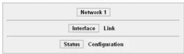
Then click Network 1 and Link at the top of the page, as shown below. The Network 1 (eth0) Ethernet Link page appears.
Figure 8-3. Network 1 Ethernet Link
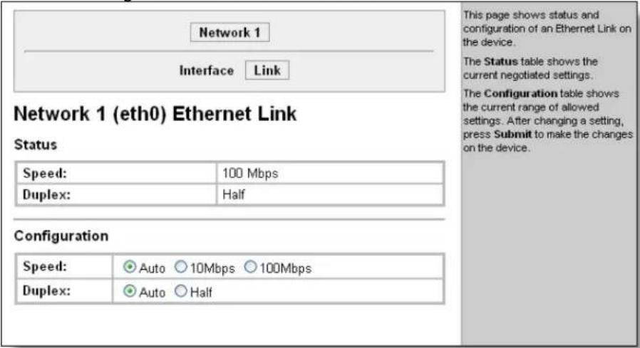
Status shows the current negotiated settings.
Configuration shows the current range of allowed settings.
- Enter or modify the following settings:
| Network 1-Ethernet Link Page Settings | Description |
| Ethernet Link Speed | Select the Ethernet link speed. (Default is Auto.) |
| Ethernet Link Duplex Select duplex mode. (Default is Auto.) | |
- Click Submit. The changes take effect immediately.
9: Line, Tunnel, Terminal, and Host Settings
Line Settings
The Line Settings pages display the status and statistics for each of the serial lines (ports). They also let you change the character format and Command Mode settings for the serial lines.
The following section describes the steps to view and configure Line settings.
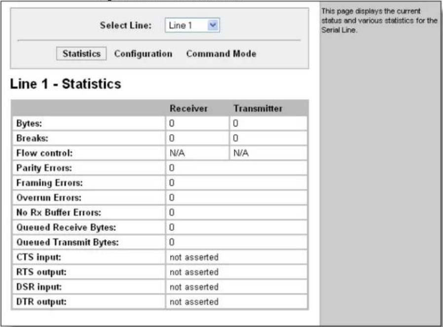
Line Statistics
This read-only page shows the status and statistics for the serial line selected at the top of this page.

Select Line on the menu bar and a Line number on the drop down list. The Line Statistics page for the selected serial line appears.
Figure 9-1. Line n Statistics
Line Configuration
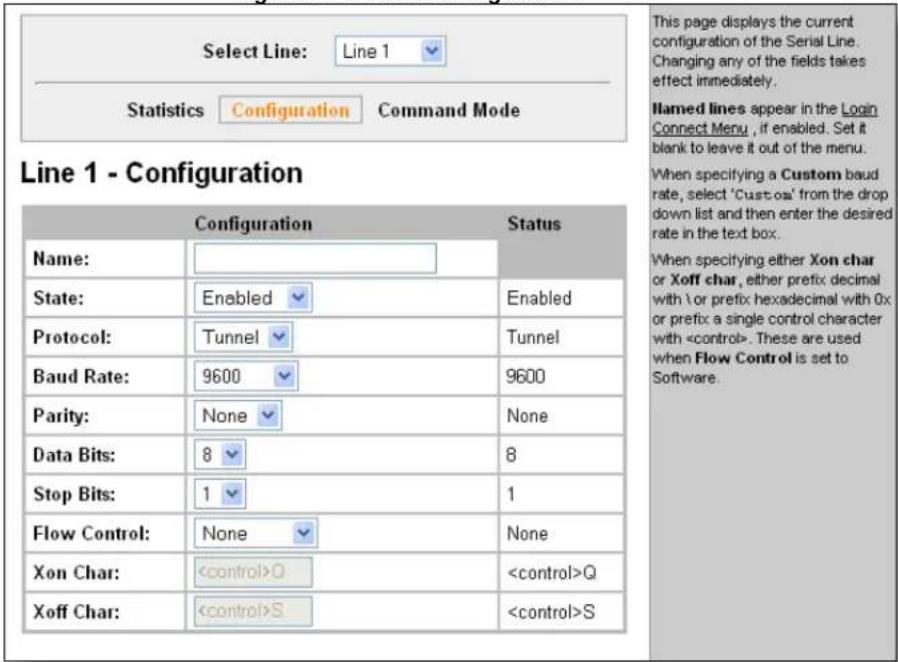
This page shows the configuration settings for the serial line selected at the top of the page and lets you change the settings for that serial line.
Configure Line n:
- Click Line n and Configuration. The Line n Configuration page appears.
Figure 9-2. Line n Configuration
- Enter or modify the following settings:
| Line -ConfigurationPage Settings | Description |
| Name | Enter a name for the line. The default Name is blank. |
| State | Indicates whether the current line is enabled. To change the state, select Enabled or Disabled from the drop-down menu. |
| Protocol | Select the protocol from the drop-down menu. The default is Tunnel. |
| Baud Rate | Select the baud rate from the drop-down menu. The default is 9600. |
| Parity | Select the parity from the drop-down menu. The default is None. |
| Data Bits | Select the number of data bits from the drop-down menu. The default is 8. |
| Stop Bits | Select the number of stop bits from the drop-down menu. The default is 1. |
| Flow Control | Select the flow control from the drop-down menu. Thedefault is None. |
| Xon Char | Specify the character to use to start the flow of data when Flow Control is set to Software. Prefix a decimal character with \ or a hexadecimal character with 0x, or provide a single printable character. The default Xon char is 0x11. |
| Xoff Char | Specify the character to use to stop the flow of data when Flow Control is set to Software. Prefix a decimal character with \ or a hexadecimal character with 0x, or provide a single printable character. The default Xoff char is 0x13. |
- Click Submit.
Line Command Mode
Setting Command Mode enables the command line interface (CLI) on the serial line.
Configure Line n Command Mode:
- Click Line n and Command Mode. The Line n Command Mode page appears.
Figure 9-3. Line n Command Mode
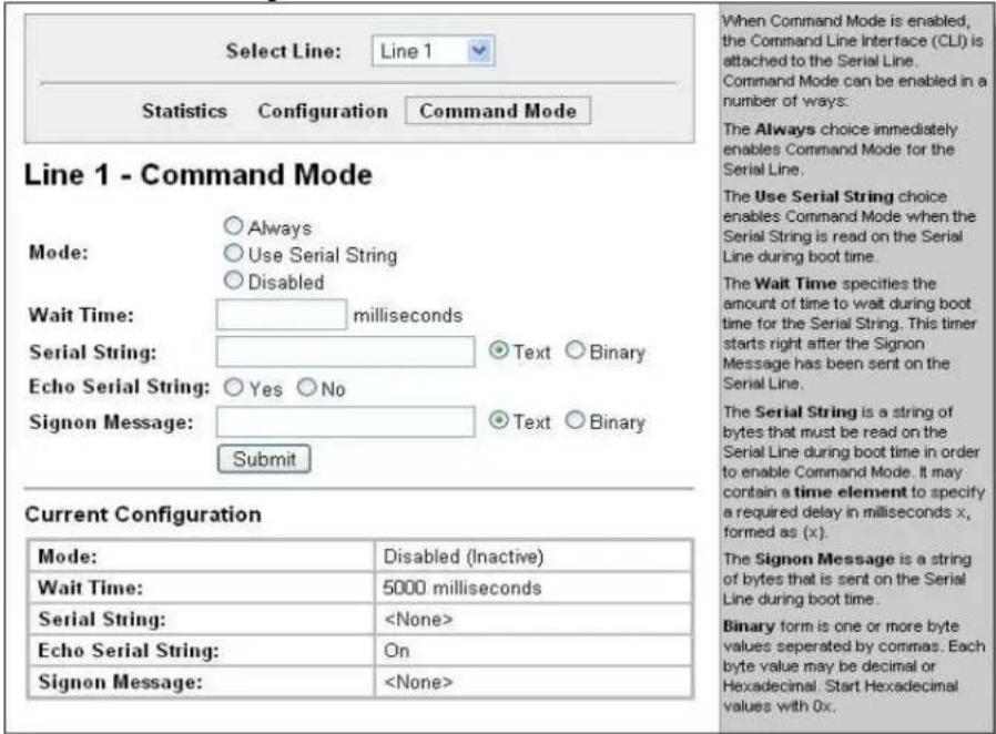
- Enter or modify the following settings:
| Line -Command ModePage Settings | Description |
| Mode | Select the method of enabling Command Mode or choose to disable Command Mode.Always=immediately enables Command Mode for the serial line.Use Serial String=enables Command Mode when the serial string is read on the serial line during boot time.Disabled=turns off Command Mode. |
| Wait Time | Enter the wait time for the serial string during boot-up in milliseconds. |
| Serial String | Enter the serial string characters. Select a string type.Text = string of bytes that must be read on the Serial Line during boot time to enable Command Mode. It may contain a time element in x milliseconds, in the format {x}, to specify arequired delay.Binary = string of characters representing byte values where each hexadecimal byte value starts with \0x and each decimal byte value starts with \. |
| Echo Serial String | Select Yes to enable echoing of the serial string at boot-up. |
| Sign-onMessage | Enter the boot-up sign-on message. Select a string type.Text = string of bytes sent on the serial line during boot time.Binary = one or more byte values separated by commas. Each byte value may be decimal or hexadecimal. Start hexadecimal values with 0x.Note: This string will be output on the serial port at boot, regardless of whether command mode is enabled or not. |
- In Current Configuration, clear currently stored settings as necessary.
- Click Submit.
Tunnel Settings
The Tunnel pages allow you to view current statistics and configure serial settings, Connect Mode, Accept Mode, Disconnect Mode, Packing Mode, start and stop characters, modem emulation, and AES keys.
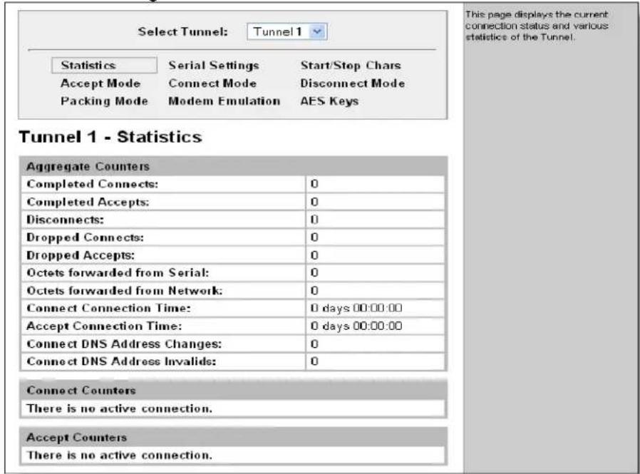
View Tunnel – Statistics

Click Tunnel on the menu bar then pick a tunnel from the drop down list. The Tunnel Statistics page appears.
Figure 9-4. Tunnel n Statistics
Accept Mode
In Accept Mode, the EDS listens (waits) for incoming connections.
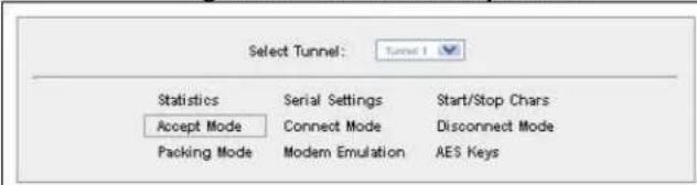
Configure Accept Mode:
- Click Tunnel n and Accept Mode at the top of the page. The Tunnel n Accept Mode page appears.
Figure 9-5. Tunnel n Accept Mode
Tunnel 1 - Accept Mode
Current Configuration
| Mode: | Enabled (Waiting) |
| Local Port: | 10001 |
| Protocol: | Top |
| Flush Serial Data: | Disabled |
| Block Serial Data: | Off |
| Block Network Data: | Off |
| TCP Keep Alives: | Default 45 seconds |
| Email on Connect: | |
| Email on Disconnect: | |
| Password: | |
| Prompt for Password: | Off |
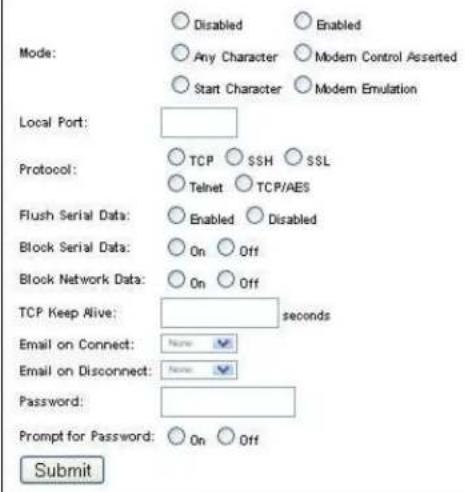
A Tunnel in Accept Mode can be started in a number of ways:
Disabled: never started
Enabled: always started
Any Character: started when any character is read on the Serial Line
Start Character: started when the Start Character is read on the Serial Line
Modem Control Asserted: started when the Modem Control pin is asserted on the Serial Line Modem Emulation: controlled via ATSO setting
The Local Port can be overridden and by default is 10001 for Tunnel 1, 10002 for Tunnel 2, and so on.
The Protocol used on the connection can be one of TCP, SSH, SSL, Telnet, or TCP w/AES. If security is a concern it is highly recommended that SSH be used. When using SSH both the SSH Server Host Keys and SSH Server Authorized Users must be configured. SSH
The Flush Serial Data boolean specifies to flush the Serial Line when a connection is made.
For debugging purposes, the Block Serial Data and Block Network Data booleans can be toggled to discard all incoming data on the respective interface.
The TCP Keep Alive timer specifies how often to probe the remote host in order to keep the TCP connection up during idle transfer periods. Enter 0 to disable.
The Password can be up to 31 characters in length and must contain only alphanumeric characters and punctuation. When set, clients must send the correct password string to the unit within 30 seconds from opening network connection in order to enable data
- Enter or modify the following settings:
| Tunnel - Accept Mode Page Settings | Description |
| Mode | Select the method used to start a tunnel in Accept mode.Choices are:Disabled = do not accept an incoming connection.Enabled = accept an incoming connection. (default)Any Character = start waiting for an incoming connection when any character is read on the serial line.Start Character = start waiting for an incoming connection when the start character for the selected tunnel is read on the serial line.Modem Control Asserted = start waiting for an incoming connection as long as the Modem Control pin (DSR) is asserted on the serial line until a connection is made.Modem Emulation = start waiting for an incoming connection when triggered by modem emulation AT commands. Connect mode must also be set to Modem Emulation. |
| Local Port | Enter the port number for use as the local port. The defaults are port 10001 for Tunnel n and port 10002 for Tunnel 2. |
| Protocol | Select the protocol type for use with Accept Mode. The default protocol is TCP. |
| Flush Serial Data | Select Enabled to flush the serial data buffer on a new connection. |
| Block Serial Data | Select On to block, or not tunnel, serial data transmitted to the EDS. |
| Block Network Data | Select On to block, or not tunnel, network data transmitted to the EDS. |
| TCP Keep Alive | Enter the time, in seconds, the EDS waits during a silent connection before checking if the currently connected network device is still on the network. If the unit then gets no response after 8 attempts, it drops that connection. |
| Email on Connect | Select whether the EDS sends an email when a connection is made. Select None if you do not want to send an email. Otherwise, select the Email profile to use for sending. |
| Email on Disconnect | Select whether the EDS sends an email when a connection is closed. Select None if you do not want to send an email. Otherwise, select the Email profile to use for sending. |
| Password | Enter a password that clients must send to the EDS within 30 seconds from opening a network connection to enable data transmission.The password can have up to 31 characters and must containonly alphanumeric characters and punctuation. When set, the password sent to the EDS must be terminated with one of the following: (a) 0x0A (LF), (b) 0x00, (c) 0x0D 0x0A (CR LF), or (d) 0x0D 0x00. |
| Prompt for Password | Indicate whether to prompt the user for the password upon connection.On = prompt for a password upon connection.Off = do not prompt for a password upon connection. |
3. Click Submit.
Packing Mode
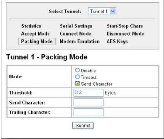
When in Packing Mode, data is not transferred one byte at a time. Instead, data is queued and sent in segments.
Configure the Tunnel Packing Mode:
- Select Tunnel n and Packing Mode at the top of the page. The Tunnel n Packing Mode page appears. Depending on the Mode selection, different configurable parameters are shown.
The following figures show the display for each of the three packing modes.
Figure 9-6a. Tunnel n Packing Mode (Mode = Disable)
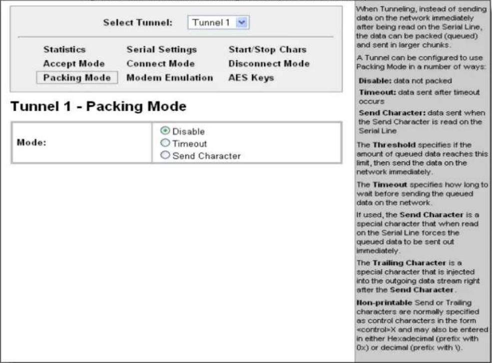
Figure 9-7b. Tunnel n Packing Mode (Mode = Timeout)
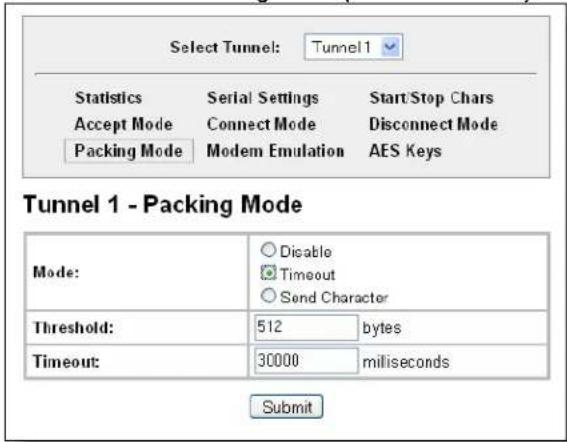
Figure 9-8c. Tunnel n Packing Mode (Mode = Send Character)
- Enter or modify the following settings:
| Tunnel - Packing Mode Page Settings | Description |
| Mode Select Disable to disable | Packing Mode completely.Select Timeout to send data after the specified time has elapsed.Select Send Character to send the queued data when the send character is received. |
| Threshold(Appears for both Timeout and Send Character Modes) | Send the queued data when the number of queued bytes reaches the threshold. |
| Timeout(Appears for Timeout Mode) | Enter a time, in milliseconds, for the EDS to send the queued data after the first character is received. |
| Send Character(Appears for Send Character Mode) | Enter the send character. The EDS immediately sends out the queued data. |
| Trailing Character(Appears for Send Character Mode) | Enter the trailing character. This character is sent immediately following the send character. |
- Click Submit.
Note: Standard and Non-printable Send or Trailing characters may be specified in either Hexadecimal (prefix with 0x) or decimal (prefix with ).
Serial Settings
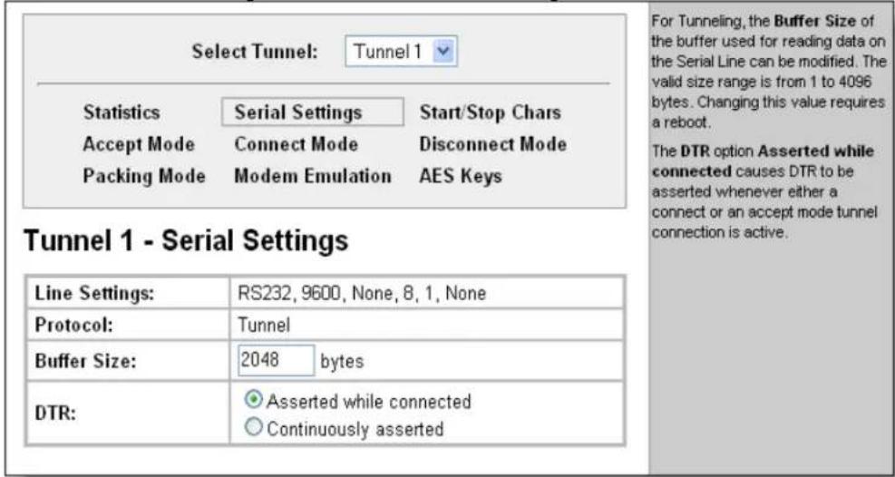
This page allows you to view and change the settings for the tunnel selected.
Configure serial settings:
- Click Tunnel n and Serial Settings at the top of the page. The Tunnel n Serial Settings page appears.
Figure 9-9. Tunnel n Serial Settings
- View or modify the following settings:
| Tunnel Serial Settings Page Settings | Description |
| Line Settings | Current serial settings for the line. |
| Protocol (display only) | The protocol being used on the line. In this case, Tunnel. |
| Buffer Size | Enter the buffer size used for the tunneling of serial data received.Requires a reboot to take effect. |
| DTR | Select when to assert DTR.Asserted while connected = asserted whenever either a connect or an accept mode tunnel connection is active.Continuously asserted = asserted regardless of the status of a tunnel connection. |
- Click Submit.
Connect Mode
Connect mode defines how the unit makes an outgoing connection.
Configure Connect Mode:
- Select Tunnel n and Connect Mode at the top of the page. The Tunnel n Connect Mode page appears.
Figure 9-10. Tunnel n Connect Mode
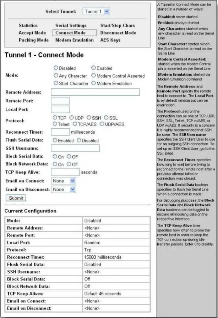
- Enter or modify the following settings:
| Tunnel – Connect Mode Page Settings | Description |
| Mode | The method to be used to connect to a remote host or device. Disabled = An outgoing connection is never attempted. (This is the default). Enabled = A connection is attempted until one is made. If the connection gets disconnected, the EDS retries until it makes a connection.Any Character = A connection is attempted when any character is read on the serial line.Modem Control Asserted = A connection is attempted as long as the Modem Control pin (DSR) is asserted, until a connection is made.Start Character = A connection is attempted when the start character for the selected tunnel is read on the serial line.Modem Emulation = A connection is attempted when triggered by modem emulation AT commands. |
| Remote Address | Enter the remote address to which the EDS will connect. Enter an IP address or DNS name. |
| Remote Port | Enter the remote port number. |
| Local Port | Enter the port for use as the local port. A random port is selected by default. Once you have configured a number, click the Random link in the Current Configuration to switch back to Random. |
| Protocol | Select the protocol type for use in Command Mode. TCP is the default protocol.The protocol can be one of TCP, UDP, SSH, SSL, Telnet, TCP with AES, or UDP with AES.If security is a concern, use SSH. The SSH Username specifies the SSH Client User to use for an outgoing SSH connection. To set up an SSH Client User, go to SSH Settings on page 93. |
| Reconnect Timer | Enter the reconnect time in milliseconds. The EDS attempts to reconnect after this amount of time after failing a connection or exiting an existing connection. |
| Flush Serial Data | Select whether to flush the serial line when a connection is made. Choices are:Enabled = flush the serial line when a connection is made level. Disabled = do not flush the serial line. (default) |
| SSH Username | Enter the SSH username. The tunnel uses the SSH keys associated with the client username. |
| Block Serial Data | Select On to block (not tunnel) serial data transmitted to the EDS. |
| Block Network Data | Select On to block (not tunnel) network data transmitted to the EDS. |
| TCP Keep Alive | Enter the time, in seconds, the unit waits during a silent connection before checking whether the currently connected network device is still on the network. If the unit then gets no response after 8 attempts, it drops that connection. |
| Email on Connect | Select whether the EDS sends an email when a connection is made. Select None if you do not want to send an email. Otherwise, select the Email profile to use. |
| Email on Disconnect | Select whether the EDS sends an email when a connection is closed. Select None if you do not want to send an email. Otherwise, select the Email profile to use. |
- Click Submit.
Modem Emulation
You can initiate a tunnel in Connect Mode using modem commands from the Serial Line.
The modem emulation page enables you to configure the modem emulation settings when you select Modem Emulation as the Tunnel n or Tunnel 2 Connect Mode type.
Configure modem emulation:
- Select Tunnel n and then Modem Emulation at the top of the page. The Tunnel n Modem Emulation page appears.
Figure 9-11. Tunnel n Modem Emulation
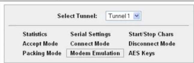
Tunnel 1 - Modem Emulation
| Configuration | Status | |
| Echo Pluses: | ○ Enabled ○ Disabled | |
| Echo Commands: | ○ Enabled ○ Disabled | Enabled |
| Verbose Response: | ○ Enabled ○ Disabled | Enabled |
| Response Type: | ○ Text ○ Numeric | Text |
| Error Unknown Commands: | ○ Enabled ○ Disabled | Disabled |
| Incoming Connection: | ○ Disabled ○ Automatic ○ Manual | Disabled |
| Connect String: | ||
| Display Remote IP: | ○ Enabled ○ Disabled |
A Tunnel in Connect Mode can be initiated using Modern commands incoming from the Serial Line.
With Echo Pluses enabled, pluses will be echoed during a "pause +++ pause" escape sequence on the Serial Line.
With Echo Commands enabled (ATE1), characters read on the Serial Line will be echoed while the Line is in Modern Command Mode.
With Verbose Response enabled (ATQ0), Modem Response Codes are sent out on the Serial Line.
Response Type selects either Text (ATV1) or Numeric (ATV0) representation for the Modem Response Codes sent out on the Serial Line.
With Error Unknown Commands enabled (ATU0), ERROR is returned for unrecognized AT commands. Otherwise (ATU1) OK is returned for unrecognized AT commands.
Incoming Connection requests may be disabled (ATS0=0), answered automatically (ATS0=1), or answered manually via the ATA command after an incoming RING (ATS0=2).
The Connect String is a customized string that is sent with the CONNECT Modem Response Code.
With Display Remote IP enabled, the incoming RING is followed by the IP address of the caller.
- Enter or modify the following settings:
| Tunnel- Modem Emulation Page Settings | Description |
| Echo Pluses | Select Enabled to echo +++ when entering modem Command Mode. |
| Echo Commands Select Enabled (same as modem command ATE1)to echo the modem commands to the console. | |
| Verbose Response Select Enabled (same as modem command ATQ0)to send modem response codes out on the serial line. | |
| Response Type Select the type of response code: Text (same as modem command ATV1) or Numeric (same as modem command ATV0). | |
| Error Unknown Commands | Select whether an ERROR or OK response is sent in reply to unrecognized AT commands. With Enabled selected (same as modem command ATU0), ERROR is returned for unrecognized AT commands. With Disabled selected (same as modem command ATU1), OK is returned for unrecognized AT commands. (default) |
| Incoming Connection: Select either Disabled (same as modem command ATS0=0), Automatic(same as modem command ATS0=1), or Manual (same as modem command ATS0=2). | |
| Connect String | Enter the connect string. This modem initialization string prepares the modem for communications. It is a customized string sent with the “CONNECT” modem response code. |
| Display Remote IP: | With Display Remote IP Enabled, the incoming RING is followed by the IP address of the caller. |
- Click Submit.
Start and Stop Characters
The Start/Stop Chars page enables you to configure the EDS to start a tunnel when it receives a specific start character from the serial port and to disconnect upon receiving the stop character.
Configure the start and stop characters mode:
- Select Tunnel n and Start/Stop Chars at the top of the page. The Tunnel n Start/Stop Chars page appears.
Figure 9-12. Tunnel n Start/Stop Chars
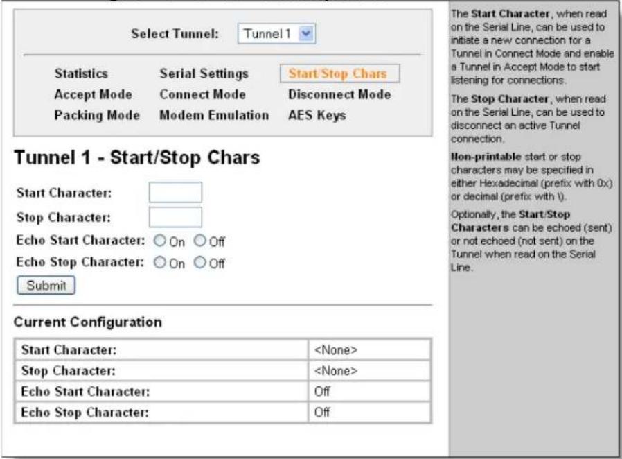
- Enter or modify the following settings:
| Tunnel – Start/Stop Chars Page Settings | Description |
| Start Character | Enter the start character in ASCII, hexadecimal, or decimal notation. |
| Stop Character | Enter the stop character in ASCII, hexadecimal, or decimal notation. |
| Echo Start Character | Select On to forward (tunnel) the start character. |
| Echo Stop Character | Select On to forward (tunnel) the stop character. |
- Click Submit.
Disconnect Mode
Disconnect Mode is disabled by default. When enabled, Disconnect Mode runs in the background of an active connection to determine when a disconnection is required.
Configure the tunnel Disconnect Mode:
- Click Tunnel n and Disconnect Mode at the top of the page. The Tunnel n Disconnect Mode page appears.
Figure 9-13. Tunnel n Disconnect Mode
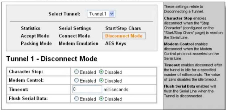
- Enter or modify the following settings:
| Tunnel – Disconnect Mode Page Settings | Description |
| Character Stop | Select Enabled to disconnect upon receiving the stop character. (See Start and Stop Characters on page 69 for instructions on configuring the stop character.) |
| Modem Control Select | Enabled to disconnect when the modem control pin is not asserted on the serial line. |
| Timeout | Enter a time, in milliseconds, for the EDS to disconnect on a timeout. The value 0 (zero) disables the idle timeout. |
| Flush Serial Data | Select Enabled to flush the serial data buffer on a disconnection. |
- Click Submit.
AES Keys
Advanced Encryption Standard (AES) is an encryption algorithm for securing sensitive information by government agencies.
Configure the AES keys for connect or Accept Mode:
- Click Tunnel n and AES Keys. The Tunnel n AES Keys page appears.
Figure 9-14. Tunnel n AES Keys
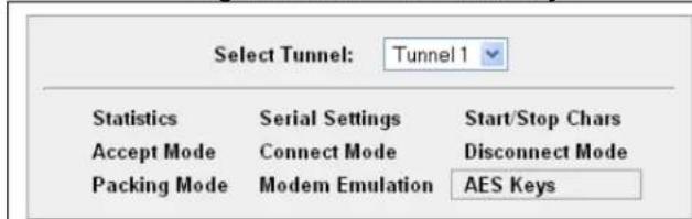
Tunnel 1 - AES Keys
Accept Mode AES Keys

Connect Mode AES Keys

There are four separate Advanced Encryption Standard (AES) Encryption Keys used for Tunneling. Connect Mode and Accept Mode contain their own sets of keys. One Key is used for encrypting outgoing data and the other Key is used for decrypting incoming data.
These AES Keys are a fixed 16 bytes in length. Any Keys entered that are less than 16 bytes long are padded with zeroes. Each key can be entered in Text or Binary form. Text form is a simple string of ASCII characters. The Binary form allows square braces [ ] to enclose one or more character designations separated by commas. Use straight decimal numbers up to 255 or hexadecimal numbers prefixed with 0x up to 0xFF. To specify an open brace in binary mode, use two in a row. Example (in Binary mode): AB[255,0xFF]C[D] Results in a string containing binary values where the dots appear: AB--C[D]
To remove a key, delete
- Enter or modify the following settings:
Note: Empty trailing byes that are not specified are set to 0.
| Tunnel – AES Keys Page Settings | Description |
| Accept Mode AES Keys | |
| Encrypt Key | Enter the value for each byte of the encryption key.Select the format for the byte as either Text or Binary.Binary form is a string of characters representing byte values where each hexadecimal byte valuestarts with \0x and each decimal byte value starts with \. |
| Decrypt Key | Enter the value for each byte of the decrypt key. Select the format for the bytes as either Text or Binary. |
| Connect Mode AES Keys | |
| Encrypt Key | Enter the value for each byte. Select the format for the byte as either Text or Binary. |
| Decrypt Key | Enter the value for each byte of the decrypt key. Select the format for the byte as either Text or Binary. |
3. Click Submit.
Terminal Settings
This page shows configuration settings for attaching a terminal on a serial line or the network and lets you change them as necessary.
Line Terminal Configuration
Configure a line to support an attached terminal:
- Click Terminal on the menu and then select the line that is connected to the terminal you want to configure. The default is Line n. Configuration is automatically selected. The Terminal on Line n Configuration page appears.
Figure 9-15. Terminal on Line n Configuration
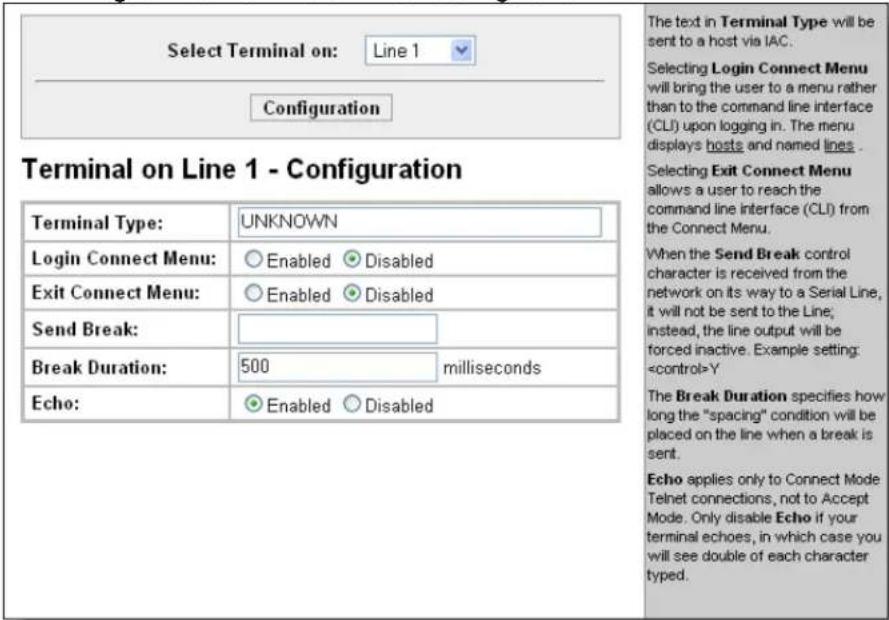
- Enter or modify the following settings:
| Terminal on Line Configuration Page Settings | Description |
| Terminal Type | Enter text to describe the type of terminal. The text will be sent to a host via IAC.Note: IAC means, “interpret as command.” It is a way to send commands over the network such as send break or start echoing. |
| Login Connect Menu | Select the interface to display when the user logs in.Choices are:Enabled = shows the Login Connect Menu.Disabled = shows the CLI |
| Exit Connect Menu | Select whether to display a choice for the user to exit the Login Connect Menu and reach the CLI. Choices are:Enabled = a choice allows the user to exit to the CLI.Disabled = there is no exit to the CLI. |
| Send Break | Enter a Send Break control character, e.g.,Y, or blank to disable.When the Send Break control character is received from the network on its way to the serial line, it is not sent to the line; instead, the line output is forced to be inactive (the break condition). |
| Break Duration | Enter how long the break should last in milliseconds. |
| Echo | Applies only to Connect Mode Telnet connections, not to Accept Mode. Only disable Echo if your terminal echoes, in which case you will see double of each character typed. |
- To save changes, click Submit.
Network Terminal Configuration
Configure menu features applicable to CLI access via the network:
- Click Terminal on the menu then Network at the top of the page. Configuration is automatically selected. The Terminal on Network Configuration page appears.
Figure 9-16. Terminal on Network Configuration
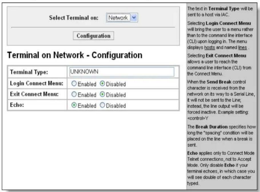
- Enter or modify the following settings:
| Terminal on Line Configuration Page | Description |
| Terminal Type | Enter text to describe the type of terminal. The text will be sent to a host via IAC.Note: IAC means, “interpret as command.” It is a way to send commands over the network such as send break or start echoing. |
| Login Connect Menu | Select the interface to display when the user logs in.Choices are:Enabled = shows the Login Connect Menu.Disabled = shows the CLI |
| Exit Connect Menu | Select whether to display a choice for the user to exit the Login Connect Menu and reach the CLI. Choices are:Enabled = a choice allows the user to exit to the CLI.Disabled = there is no exit to the CLI. |
| Echo | Applies only to Connect Mode Telnet connections, not to Accept Mode. Only disable Echo if your terminal echoes, in which case you will see double of each character typed. |
3. Click Submit.
Host Configuration
This page shows current settings for a remote host and lets you change these settings. Use these settings to add host destinations to the Login Connect Menu.
- Click Host on the menu and then click the desired host at the top of the page. Configuration is automatically selected. (Host 1 is the default.) The Host Configuration page appears.
Figure 9-17. Host Configuration
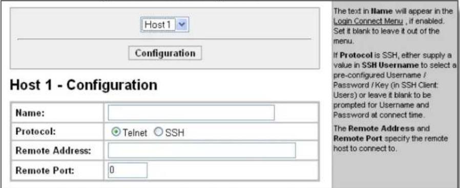
- Enter or modify the following settings:
| Host Page Settings | Description |
| Name | A name for the host. This name appears on the Login Connect Menu. To leave a host out of the menu, leave this field blank. |
| Protocol | The protocol to use to connect to the host. Choices are:TelnetSSHNote: SSH keys must be loaded or created on the SSH page for the SSH protocol to work. |
| SSHUsername | Appears if you selected SSH as the protocol.Enter a username to select a pre-configured Username/Password/Key (configured on the SSH: Client Users page),—Or—Leave it blank to be prompted for a username and password at connect time. |
| Remote Address | IP address for the host. |
| Remote Port | Port on the host to which the EDS will connect. |
3. Click Submit.
Login Connect Menu
As an administrator, you can set up a menu on the EDS for terminal users.
For a terminal attached to serial Line N, set as follows:
■ Line[N] Protocol = None
■ Line[N] Command Mode = Always
- Terminal[Line N] Login Connect Menu = Enabled.
For Telnet-attached terminals, set:
- Terminal [Network] Login Connect Menu = Enabled.
You will see a menu like this:
Password :
Connection menu: (select by number)
1) Alpha 2) Beta
3) Exit to command line interface 4) Log out Selection =
- Add a destination serial line M to the menu by filling in Line[M] Name. For this purpose, set:
■ Line[M] Protocol = None
■ Line[M] Command Mode = Disabled.
- Add a network destination to the menu by setting up a Host entry for it. Each named Host entry will appear in the menu.
- Add the Exit to command line interface choice to the menu by setting: Terminal[Line N] or Terminal[Network] Exit Connect Menu = Enabled.
The Log out choice is always present.
Preview the Login Connect Menu
The Login Connect Menu can be previewed without actually connecting in via a serial line or telnet connection.
From the Web Manager, go to the Terminal page. If "Login Connect Menu" is enabled, you will see a preview layout in the lower part of the page.
From the Command Line Interface, go to the config-terminal level. Use the "preview connect menu" command.
10: Services Settings
DNS Configuration
This page shows the active run-time settings for the domain name system (DNS) protocol. The primary and secondary DNS addresses come from the active interface. The static addresses from the Network Interface Configuration page may be overridden by DHCP or BOOTP.
The DNS page also shows any contents in the DNS cache. When a DNS name is resolved using a forward lookup, the results are stored in the DNS cache temporarily. The EDS consults this cache when performing forward lookups. Each item in the cache eventually times out and is removed automatically after a certain period, or you can delete it manually.
View the EDS DNS configuration:
One Step Click DNS on the menu bar. The DNS page appears.
Figure 10-1. DNS Settings
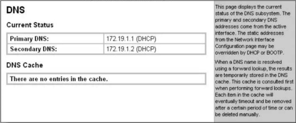
SNMP Configuration
This page is used to configure the Simple Network Management Protocol (SNMP) agent. Using this page, you can configure the SNMP service to send a trap when it receives a request for information that contains an incorrect community name and does not match an accepted system name for the service.
Configure SNMP:
- Click SNMP on the menu bar. The SNMP page opens and shows the current SNMP configuration.
Figure 10-2. SNMP Configuration
![SNMP SNMP Agent: ○ On ○ Off Read Community: Write Community: System Contact: System Name: System Description: System Location: Enable Traps: ○ On ○ Off Primary Trap Dest IP: Secondary Trap Dest IP: Submit Current Configuration SNMP Agent Status: Running (On) Read Community: [Delete] Write Community: [Delete] System Contact: System Name: EDS8PS [Delete] System Description: System Location: Traps Enabled: On Primary Trap Dest IP: Secondary Trap Dest IP: This page displays the current configuration of the SNMP Agent.](/content/2026/05/1028534/images/25eb694c81b916fbb4aa7babe9c2297eafb6fa550bebd0052eb4e3b02e945db6.jpg)
- Enter or modify the following settings:
| SNMP Page Settings Description | |
| SNMP Agent Select On to | enable SNMP. |
| Read Community Enter the | SNMP read-only community string. |
| Write Community Enter the | SNMP read/write community string. |
| System Contact Enter the | name of the system contact. |
| System Name Enter the system name. | |
| System Description Enter the | system description. |
| System Location Enter the | system location. |
| Enable Traps Select On to | enable the transmission of the SNMP cold start trap messages. This trap is generatedduring system boot. |
| Primary Trap Dest IP Enter the primary SNMP trap host. | |
| Secondary Trap Dest IP Enter the secondary SNMP trap host. | |
- Click Submit.
- In the Current Configuration table, delete and clear currently stored settings as necessary.
FTP Configuration
This page shows the current File Transfer Protocol (FTP) configuration and connection status and various statistics about the FTP server.
Configure FTP:
- Click FTP on the menu bar. The FTP page opens to display the current configuration.
Figure 10-3. FTP Configuration
![FTP FTP Server: ○ On ○ Off Username: Password: Submit Current FTP Configuration and Statistics FTP Status: On (running) FTP Username: admin FTP Password: [Reset] Connections Rejected: 0 Connections Accepted: 0 Active Connections: 0 Last Client: No device has connected This page displays the current connection status and various statistics for the FTP Server.](/content/2026/05/1028534/images/dec6babf43d8f60790288e47a0cbb9ae1c3c6c10b74a152d536fadb8c864624b.jpg)
- Enter or modify the following settings:
| FTP Page Settings | Description |
| FTP Server Select On to enable the FTP server. | |
| Username | Enter the username to use when logging in via FTP. |
| Password | Enter the password to use when logging in via FTP. |
3. Click Submit.

Click [Reset] to reset the FTP Password.
TFTP Configuration
This page shows the status and various statistics about the Trivial File Transfer Protocol (TFTP) server.
Configure TFTP:
- Click TFTP on the menu bar. The TFTP page opens to display the current configuration.
Figure 10-4. TFTP Configuration
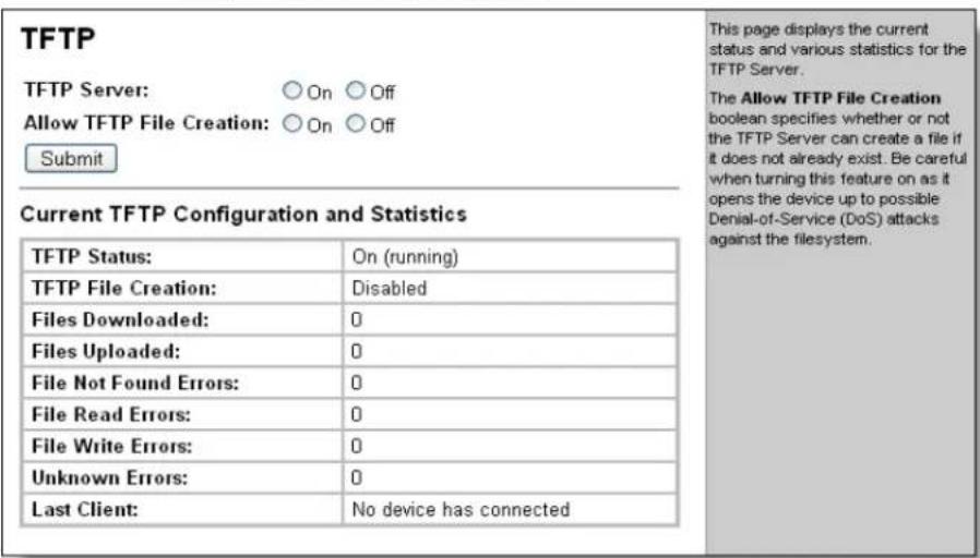
- Enter or modify the following settings:
| TFTP Page Settings Description | |
| TFTP Server Select On | to enable the TFTP server. |
| Allow TFTP File Creation | Select whether to allow the creation of new files stored on the TFTP server. |
- Click Submit.
Syslog Configuration
The Syslog page shows the current configuration, status, and statistics of the syslog. Here you can configure the syslog destination and the severity of the events to log.
Note: The system log is not retained through reboots. Saving the system log to a server that supports remote logging services (see RFC 3164) allows the administrator to save the complete system log history. The default port is 514.
- Click Syslog on the menu bar. The Syslog page opens to display the current configuration.
Figure 10-5. Syslog
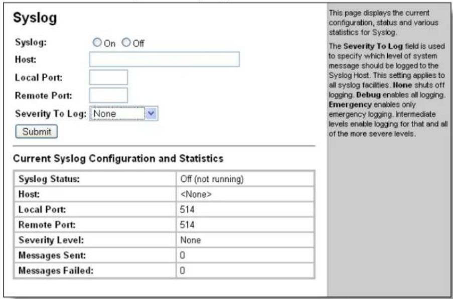
- Enter or modify the following settings:
| Syslog Page Settings | Description |
| Syslog | Select to enable or disable the syslog. |
| Host | Enter the IP address of the remote server to which system logs are sent for storage. |
| Local Port | Enter the number of the local port on the EDS from which system logs are sent. |
| Remote Port | Enter the number of the port on the remote server that supports logging services. The default is 514. |
| Severity to Log | From the drop-down box, select the minimum level of system message the EDS should log. This setting applies to all syslog facilities. The drop-down list is in descending order of severity (e.g., Emergency is more severe than Alert.). Message logging will include all severities up to the selected level. Selecting the Debug severity will log all system message. |
HTTP Configuration
Hypertext Transfer Protocol (HTTP) is the transport protocol for communicating hypertext documents on the Internet.
HTTP defines how messages are formatted and transmitted. It also defines the actions web servers and browsers should take in response to different commands.
This page has three links at the top for viewing statistics and for viewing and changing configuration and authentication settings.
HTTP Statistics
Note: The HTTP log is a scrolling log, with the last Max Log Entries cached and viewable. You can change the maximum number of entries that can be viewed on the HTTP Configuration Page.
View HTTP statistics:

Click HTTP on the menu bar and then Statistics at the top of the page. The HTTP Statistics page appears.
Figure 10-6. HTTP Statistics
![Statistics Configuration Authentication This page displays the various HTTP Server statistics. The HTTP Log is a scrolling log in that only the last Max Log Entries lines are cached and viewable. This maximum number of entries can be modified on the HTTP Configuration page. HTTP Statistics Rx Bytes 144287 Tx Bytes 1237753 200 - OK 205 400 - Bad Request 1 401 - Authorization Required 8 404 - Not Found 0 408 - Request Timeout 0 413 - Request Too Large 0 501 - Not Implemented 0 Status Unknown 0 Work Queue Full 0 Socket Error 0 Memory Error 0 Logs: 50 entries (7334 bytes) [View] [Clear]](/content/2026/05/1028534/images/07fa69ed2d3fb8c8d5c4fe4f6c57487c209c4b30ab2f03fa5f34df85bf50eda9.jpg)
Change HTTP Configuration
On this page you can change HTTP configuration settings.
Configure HTTP:
- Click HTTP on the menu bar and then Configuration at the top of the page. The HTTP Configuration page opens.
Figure 10-7. HTTP Configuration
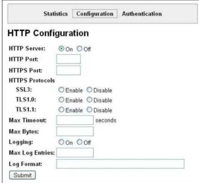
Current Configuration
| HTTP Status: | On (running) |
| HTTP Port: | 80 |
| HTTPS Port: | 443 |
| HTTPS Protocols: | SSL3, TLS1.0, TLS1.1 |
| Max Timeout: | 10 seconds |
| Max Bytes: | 40960 |
| Logging: | On |
| Max Log Entries: | 50 |
| Log Format: | %h %t "%r" %s %B "%(Referer)i" "%(User-Agent)i" |
| Logs: | 50 entries (7307 bytes) [View] [Clear] |
Both the HTTP Port and HTTPS Port (SSL) can be overridden. The HTTP Server will only listen on the HTTPS Port when an SSL Certificate is configured for the device and at least one SSL protocol version is enabled in HTTPS Protocols.
The Max Timeout value specifies the maximum amount of time to wait for a request from a client. The Max Bytes value specifies the maximum number of bytes allowed in a client request. Both of these values are used to help prevent Denial of Service (DoS) attacks against the HTTP Server.
The HTTP Log is a scrolling log in that only the last Max Log Entries lines are cached and viewable.
Log Format Directives
| %a | remote IP address (could be a proxy) |
| %b | bytes sent excluding headers |
| %B | bytes sent excluding headers (0 = '-') |
| %h | remote host (same as '%a') |
| %(h)i | header contents from request (h = header string) |
| %m | request method |
| %p | ephemeral local port value used for request |
| %q | query string (prepend with '?' or empty '-' ) |
| timestamp HH:MM:SS(same as Apache"%(%H:%M:%S)‘ or"%(%T)‘) | |
| %t | |
| %u | remote user (could be bogus for 401 status) |
| %U | URL path info |
| %r | first line of request (same as %m %U%q <version>) |
| %s | return status |
| The max length for each directive is 64 bytes. The exception is '%r' where each element is limited to 64 bytes (i.e. method, URL path info, and query string). | |
- Enter or modify the following settings:
| HTTP Configuration | Description |
| HTTP Server | Select On to enable the HTTP server. |
| HTTP Port | Enter the port for the HTTP server to use. The default is 80. |
| HTTPS Port | Enter the port for the HTTPS server to use. The default is 443. The HTTP server only listens on the HTTPS Port when an SSL certificate is configured. |
| HTTPS Protocols | Select to enable or disable the following protocols:SSL3 = Secure Sockets Layer version 3TLS1.0 = Transport Layer Security version 1.0. TLS 1.0 is the successor of SSL3 as defined by the IETF.TLS1.1 = Transport Layer Security version 1.1The protocols are enabled by default. A server certificate and associated private key need to be installed in the SSL configuration section to use HTTPS. |
| Max Timeout | Enter the maximum time for the HTTP server to wait when receiving a request. This prevents Denial-of-Service (DoS) attacks. The default is 10 seconds. |
| Max Bytes | Enter the maximum number of bytes the HTTP server accepts when receiving a request. The default is 40 kB (this prevents DoS attacks). |
| Logging Select | On to enable HTTP server logging. |
| Max Log Entries | Sets the maximum number of HTTP server log entries. Only the last Max Log Entries are cached and viewable. |
| Log Format | Set the log format string for the HTTP server. Follow these Log Format rules:%a - remote IP address (could be a proxy)%b - bytes sent excluding headers%B - bytes sent excluding headers (0 = '-')%h - remote host (same as '%a')%(h)i - header contents from request (h = header string)%m - request method%p - ephemeral local port value used for request%q - query string (prepend with '?' or empty '-'%)t - timestamp HH:MM:SS (same as Apache'%(%H:%M:%S)t' or '%(%T)t')%u - remote user (could be bogus for 401 status%)U - URL path info%r - first line of request (same as '%m %U%q')%s - return status |
- Click Submit.
HTTP Authentication
HTTP Authentication enables you to require usernames and passwords to access specific web pages or directories on the EDS's built-in web server.
More than one Username per URI is permitted. Click Submit and enter the next Username as necessary.
The URI, realm, username, and password are user-specified, free-form fields. The URI must match the directory created on the EDS file system.
Configure HTTP authentication settings:
- Click HTTP on the menu bar then Authentication at the top of the page. The HTTP Authentication page opens.
Figure 10-8. HTTP Authentication
![Statistics Configuration Authentication HTTP Authentication URI: Realm: AuthType: None Basic Digest SSL SSL/Basic SSL/Digest Username: Password: Submit Current Configuration URI: / [Delete] Realm: config AuthType: Digest Users: admin [Delete] The HTTP Server can be configured with many different authentication directives. The authentication is hierarchical in that any URI can be given an authentication directive in order to override a parent URI authentication directive. The URI must begin with / to refer to the filesystem. The different AuthType values offer various levels of security. From the least to most secure: None no authentication necessary Basic encodes passwords using Base64 Digest encodes passwords using MD5 SSL page can only be accessed over SSL (no password) SSL/Basic page can only be accessed over SSL (encodes passwords using Base64) SSL/Digest page can only be accessed over SSL (encodes passwords using MD5) Note that SSL by itself does not require a password but all data transferred to and from the HTTP Server is encrypted. There is no real reason to create an authentication directive using None unless you want to override a parent directive that uses some other AuthType. Multiple users can be configured within a single authentication directive.](/content/2026/05/1028534/images/8a804350fba8224c2135fe04e987b7ddb95d2cd41d74d45d0015ac8b2a52e482.jpg)
- Enter or modify the following settings:
| HTTP Authentication Settings | Description |
| URI | Enter the Uniform Resource Identifier (URI).The URI must begin with ‘/’ to refer to the file system. |
| Realm | Enter the domain, or realm, used for HTTP. Required with the URI field. |
| Auth Type | Select the authentication type:None = no authentication is necessary.Basic = encodes passwords using Base64.Digest = encodes passwords using MD5.SSL = the page can only be accessed over SSL (no password is required).SSL/Basic = the page is accessible only over SSL and encodes passwords using Base64.SSL/Digest = the page is accessible only over SSL and encodes passwords using MD5. |
| Username | Enter the Username used to access the URI. |
| Password | Enter the Password for the Username. |
- Click Submit.
- In the Current Configuration table, delete and clear the currently stored settings as necessary.
RSS Settings
EDS devices support RSS feeds with up-to-date information about configuration changes. RSS feeds allow you to view new information about changes made to the EDS over the web.
On the RSS Settings page, you can turn RSS feeds on or off. On means the device will create RSS feeds and make them accessible. RSS feeds may be viewed online or saved to the file system cfg_log.txt file.
Tip: To view the EDS RSS feed from your browser, enter the IP address of the device. You will be prompted whether you want to subscribe to the device RSS feed. Once you subscribe, you can view the RSS feed.
Configure RSS settings:
- Click RSS on the menu bar. The RSS page opens and shows the current RSS configuration.
Figure 10-9. RSS
![RSS RSS Feed: ○ On ● Off Persistent: ○ On ● Off Max Entries: 100 Current Status Data: 0 entries (0 bytes) [View] [Clear] An RDF Site Summary (RSS) syndication feed is served by the HTTP Server. This feed contains up-to-date information regarding the configuration changes that occur on the device. Specifying the RSS Feed to be Persistent results in the data being stored on the filesystem. The file used is "/cfg_log.txt". This allows feed data to be available across reboots (or until the factory defaults are set). Each RSS Feed entry contains a standard timestamp in its field. The RSS Feed is a scrolling feed in that only the last Max Entries entries are cached and viewable. Simply register the RSS Feed within your favorite RSS aggregator and you will automatically be notified of any configuration changes that occur.](/content/2026/05/1028534/images/c1e0f7d16ba22b9ce75967b92d161835f38d2aded9d1369a2a8a5e187ce70175.jpg)
- Enter or modify the following settings:
| RSS Page Settings | Description |
| RSS Feed Select On to create RSS feeds. | |
| Persistent | Select On to write the RSS feed to a file (cfg_log.txt) and to remain across reboots. |
| Max Entries | Sets the maximum number of log entries. Only the most recent number of Max Entries are cached and viewable. |
-
Click Submit.
-
In the Current Status table, view and clear stored settings as necessary.
LPD Settings
In addition to its other functions, the EDS acts as a print server if a printer is connected to one of its serial ports.
Clicking the LPD (Line Printer Daemon) link in the menu bar, shows a LPD page. This page has three links at the top for viewing print queue statistics, changing print queue configuration, and printing a test page.
Because the LPD lines operate independently, you can specify different configuration settings for each.
LPD Statistics Page
This read-only page shows various statistics about the LPD server.
View LPD statistics:

Click LPD on the menu bar, then select the LPD line from the drop down list, and click Statistics. The LPD page shows the LPD statistics.
Figure 10-10. LPD Statistics
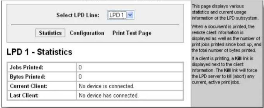
LPD Configuration Page
Here you can change LPD configuration settings.
Configure LPD settings:
- Click LPD on the menu bar, select the LPD line and click Configuration. The LPD Configuration page appears.
Figure 10-11. LPD Configuration
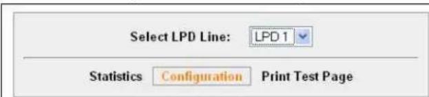
LPD 1 - Configuration
| WARNING: Serial protocol is not "LPD": | |
| Banner: | Enabled Disabled |
| Binary: | Enabled Disabled |
| Start of Job: | Enabled Disabled |
| End of Job: | Enabled Disabled |
| Formfeed: | Enabled Disabled |
| Convert Newlines: | Enabled Disabled |
| SOJ String: | |
| Text Binary | |
| EOJ String: | |
| Text Binary | |
| Queue Name: | |
Enabling Banner will force the banner page to be printed even if the incoming print job does not specify to do so.
Enabling Binary will pass the entire file to the printer without removing any characters. Disabled, only valid ascii and control characters are passed, all others are stripped. Valid control characters include the tab, linefeed, formfeed, backspace, and newline.
Enabling Formfeeds will force a formfeed to be sent to the printer at the end of each print job.
Enabling Convert Hewlines will convert single newlines and single carriage returns into DOS style carriage return + linefeed line endings; if carriage return and linefeed characters are already in the correct DOS line-ending order, they will remain unchanged.
To send a Start Of Job (SOJ) or End Of Job (EOJ) string to the printer, enter the appropriate string. The SOJ and EOJ strings are limited to 100 characters each (after possible conversion to binary).
The SOJ and EOF strings can be entered in Text or Binary form. The Binary form allows square braces [ ] to enclose one or more character designations separated by commas. Use straight decimal numbers up to 255 or hexadecimal numbers prefixed with 0x up to 0xFF within the square braces. To specify an open brace in binary mode, use two in a row. Example (in Binary mode):
AB[255,0xFF]C[[D] Results in a string containing binary values where the dots appear. AB··C[D] A Queue llame may not contain white space.
- Enter or modify the following settings:
| LPDConfigurationPage Settings | Description |
| Banner Select Enabled to print the banner even if the print job does not specify to do so. Selected by default. | |
| Binary Select Enabled for the EDS to pass the entire file to the printer unchanged. Otherwise, the EDS passes only valid ASCII and valid control characters to the printer. Valid control characters include the tab, linefeed, formfeed, backspace, and newline characters. All others are stripped. Disabled by default. | |
| Start of Job | Select Enabled to print a "start of job" string before sending the print data. |
| End of Job Select Enabled to send an "end of job" string. | |
| Formfeed Select Enabled to force the printer to advance to the next page at the end of each print job. | |
| Convert Newlines | Select Enabled to convert single newlines and carriage returns to DOS-style line endings. |
| SOJ String | If Start of Job (above) is enabled, enter the string to be sent to the printer at the beginning of a print job. The limit is 100 characters.Indicate whether the string is in text or binary format. |
| EOJ String | If End of Job (above) is enabled, enter the string to send at the end of a print job. The limit is 100 characters. Indicate whether the string is in text or binary format. |
| Queue Name | To change the name of the print queue, enter a new name. The name cannot have white space in it and is limited to 31 characters. The default is LPDQueueX (for line number X) |
11: Security Settings
SSH and SSL are protocols for managing the security of data transmissions over the Internet.
SSH Settings
Secure Shell (SSH) is a protocol used to access a remote computer over an encrypted channel. It is a protocol for managing the security of data transmission over the Internet. It provides encryption, authentication, and message integrity services. This page has four links at the top for viewing and changing SSH server host keys, SSH server authorized keys, SSH client known hosts, and SSH client users.
SSH Server Host Keys
Configure the SSH server host keys:
- Click SSH on the menu bar. The SSH Server: Host Keys page appears.
Figure 11-1. SSH Server: Host Keys
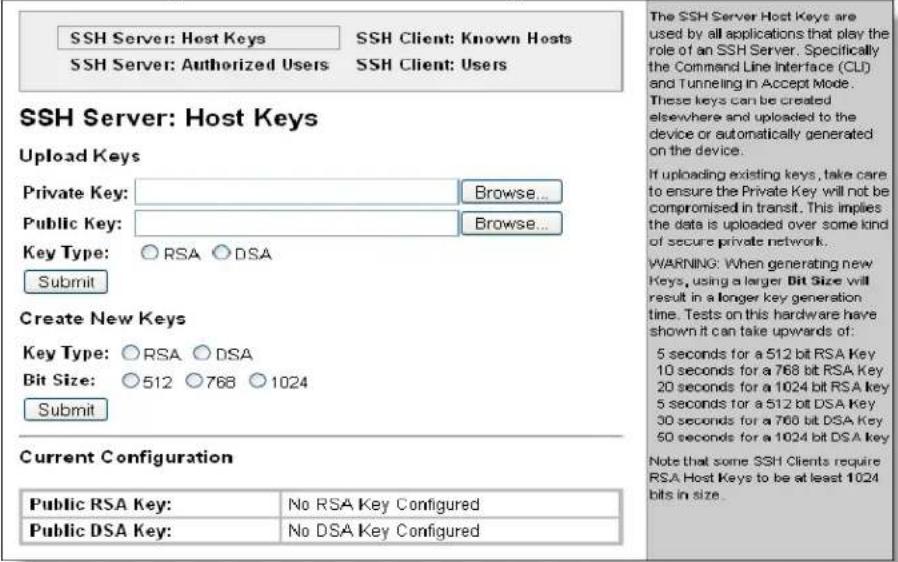
- Enter or modify the following settings:
| SSH Server: Host Keys | Description |
| Upload Keys | |
| Private | Enter the path and name of the existing private key you want to |
| Key upload or use the Browse button to select the key. Be sure the private key will not be compromised in transit. This implies the data is uploaded over some kind of secure private network. | |
| Public Key | Enter the path and name of the existing public key you want to upload or use the Browse button to select the key. |
| Key Type | Select a key type to use: RSA = use this key with SSH1 and SSH2 protocols.DSA = use this key with the SSH2 protocol. |
| Create New Keys | |
| Key Type | Select a key type to use for the new key: RSA = use this key with the SSH1 and SSH2 protocols.DSA = use this key with the SSH2 protocol. |
| Bit Size | Select a bit length for the new key: 5127681024Using a larger bit size takes more time to generate the key. Approximate times are: 10 seconds for a 512 bit RSA Key 15 seconds for a 768 bit RSA Key 1 minute for a 1024 bit RSA key 30 seconds for a 512 bit DSA key 1 minute for a 768 bit DSA key 2 minutes for a 1024 bit DSA keySome SSH clients require RSA host keys to be at least 1024 bits long. Note: EDS4100 generates keys up to 1024 bits long. It can work with larger keys (up to 2048 bit) if they are imported or otherwise created. |
- Click Submit.
SSH Server Authorized Users
On the SSH Server page you can change SSH server settings for Authorized Users.
- SSH Server Authorized Users are accounts on the EDS that can be used to log into the EDS using SSH.
For instance, these accounts can be used to SSH into the CLI or open an SSH connection to a device port.
◆ Every account must have a password.
The users' public keys are optional and only necessary if public key authentication is required. Using public key authentication allows a connection to be made without the password prompt.
Under Current Configuration, User has a Delete User link, and Public RSA Key and Public DSA Key have View Key and Delete Key links.
Configure the SSH server for authorized users:
- Click SSH on the menu bar and then Server Authorized Users at the top of the page. The SSH Server: Authorized Users page appears.
Figure 11-2. SSH Server: Authorized Users
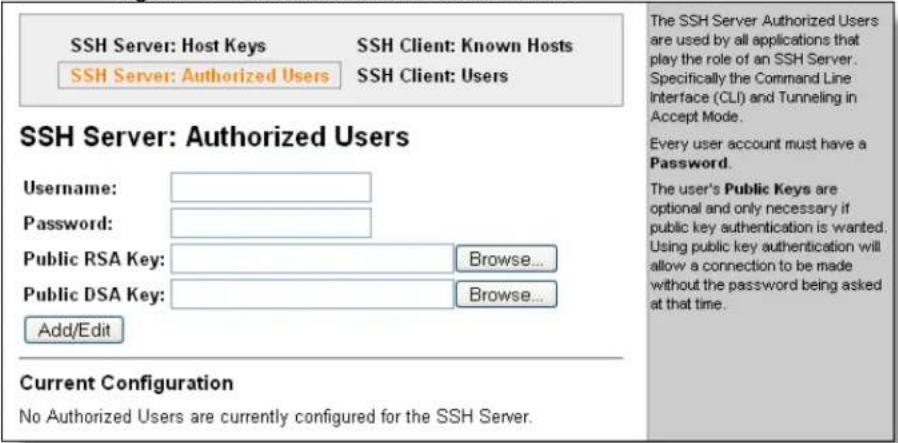
- Enter or modify the following settings:
| SSH Server: Authorized Users Page Settings | Description |
| Username | Enter the name of the user authorized to access the SSH server. |
| Password | Enter the password associated with the username. |
| Public RSA Key | Enter the path and name of the existing public RSA key you want to use with this user or use theBrowsebutton to select the key. If authentication is successful with the key, no password is required. |
| Public DSA Key | Enter the path and name of the existing public DSA keyyou want to use with this user or use theBrowsebutton to select the key. If authentication is successful with the key, no password is required. |
3. Click Submit.
SSH Client Known Hosts
On this page you can change SSH client settings for known hosts.
Note: You do not have to complete the fields on this page for communication to occur. However, completing them adds another layer of security that protects against Man-In-The-Middle (MITM) attacks.
Configure the SSH client for known hosts:
- Click SSH on the menu bar and then Client Known Hosts at the top of the page. The SSH Client: Known Hosts page appears.
Figure 11-3. SSH Client: Known Hosts
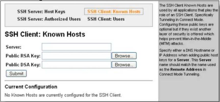
- Enter or modify the following settings:
| SSH Client: Known Hosts | Description |
| Server | Enter the name or IP address of a known host. If you enter a server name, the name should match the name of the server used as the Remote Address in Connect mode tunneling. |
| Public RSA Key | Enter the path and name of the existing public RSA key you want to use with this known host or use the Browse button to select the key. |
| Public DSA Key | Enter the path and name of the existing public DSA key you want to use with this known host or use the Browse button to select the key. |
Note: These settings are not required for communication. They protect against Man-In-The-Middle (MITM) attacks.
- Click Submit.
- In the Current Configuration table, delete currently stored settings as necessary.
SSH Client User Configuration
On this page you can change SSH client settings for users.
SSH client known users are used by all applications that play the role of an SSH client, specifically tunneling in Connect Mode. At the very least, a password or key pair must be configured for a user. The keys for public key authentication can be created elsewhere and uploaded to the device or automatically generated on the device. If uploading existing keys, be sure the private key will not be compromised in transit. This implies the data is uploaded over some kind of secure private network.
Note: If you are providing a key by uploading a file, make sure that the key is not password protected.
Configure the SSH client users:
- Click SSH on the menu bar and then SSH Client Users at the top of the page. The SSH Client: Users page appears.
Figure 11-4. SSH Client: Users
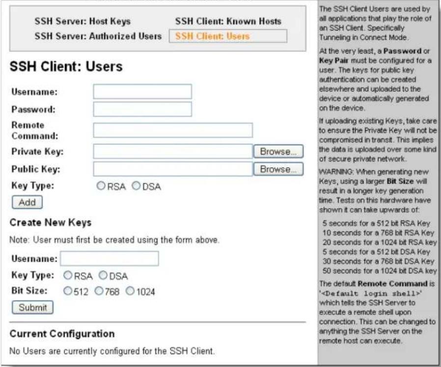
- Enter or modify the following settings:
| SSH Client:Users Page Settings | Description |
| Username | Enter the name that the EDS uses to connect to a SSH server. |
| Password | Enter the password associated with the username. |
| Remote Command | Enter the command that can be executed remotely. Default is shell, which tells the SSH server to execute a remote shell upon connection. This command can be changed to anything the remote host can perform. |
| Private Key | Enter the name of the existing private key you want to use with this SSH client user. You can either enter the path and name of the key, or use theBrowsebutton to select the key. |
| Public Key | Enter the path and name of the existing public key you want to use with this SSH client user or use theBrowsebutton to select the key. |
| Key Type | Select the key type to be used. Choices are:RSA= use this key with the SSH1 and SSH2 protocols.DSA= use this key with the SSH2 protocol. |
| Create New Keys | |
| Username | Enter the name of the user associated with the new key. |
| Key Type | Select the key type to be used for the new key. Choices are:RSA= use this key with the SSH1 and SSH2 protocols.DSA= use this key with the SSH2 protocol. |
| Bit Size | Select the bit length of the new key:5127681024Using a larger Bit Size takes more time to generate the key.Approximate times are:10 seconds for a 512 bit RSA Key15 seconds for a 768 bit RSA Key1 minute for a 1024 bit RSA key30 seconds for a 512 bit DSA key1 minute for a 768 bit DSA key2 minutes for a 1024 bit DSA keySome SSH clients require RSA host keys to be at least 1024 bits long. |
- Click Submit.
- In the Current Configuration table, delete currently stored settings as necessary.
SSL Settings
Secure Sockets Layer (SSL) is a protocol for managing the security of data transmission over the Internet. It provides encryption, authentication, and message integrity services. SSL is widely used for secure communication to a web server.
Certificate/Private key combinations can be obtained from an external Certificate Authority (CA) and downloaded into the unit. Self-signed certificates with associated private key can be generated by the device server itself.
For more information regarding Certificates and how to obtain them see Obtaining a Certificate and Private Key on page 146.
Configure the EDS SSL settings:
- Click SSL from the main menu. The SSL page appears.
Figure 11-5. SSL
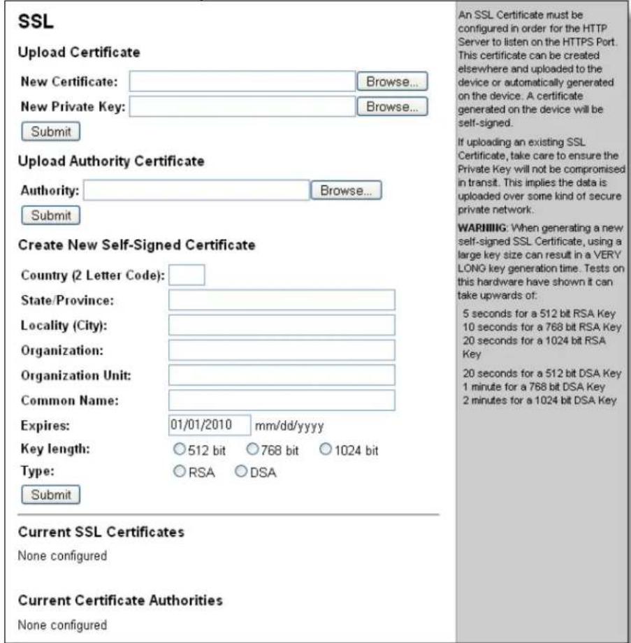
- Enter or modify the following settings:
| SSL Page Settings | Description |
| Upload Certificate | |
| New Certificate | This certificate identifies the EDS to peers. It is used for HTTPS and SSL Tunneling.Enter the path and name of the certificate you want to upload, or use theBrowsebutton to select the certificate.RSAor DSAcertificates with 512 to 1024 bit public keys are allowed.The format of the file must bePEM. The file must start with “----BEGIN CERTIFICATE----” and end with “----END CERTIFICATE----”. Some Certificate Authorities add comments before and/or after these lines. Those need to be deleted before upload. |
| New Private Key | Enter the path and name of the private key you want to upload, or use theBrowsebutton to select the private key. The key needs to belong to the certificate entered above.The format of the file must bePEM. The file must start with “----BEGIN RSA PRIVATE KEY----” and end with “----END RSA PRIVATE KEY----”. Read DSAinstead of RSAin case of a DSAkey. Some Certificate Authorities add comments before and/or after these lines. Those need to be deleted before upload. |
| Upload Authority Certificate | |
| Authority | One or more authority certificates are needed to verify a peer's identity. It is used for SSL Tunneling. These certificates do not require a private key.Enter the path and name of the certificate you want to upload, or use theBrowsebutton to select the certificate.RSAor DSAcertificates with 512 to 1024 bit public keys are allowed.The format of the file must bePEM. The file must start with “----BEGIN CERTIFICATE----” and end with “----END CERTIFICATE----”. Some Certificate Authorities add comments before and/or after these lines. Those need to be deleted before upload. |
| Create New Self-Signed Certificate | |
| Country (2 Letter Code) | Enter the 2-letter country code to be assigned to the new self-signed certificate.Examples:US for United States and CA for Canada |
| State/Province | Enter the state or province to be assigned to the new self-signed certificate. |
| Locality (City) | Enter the city or locality to be assigned to the new self-signed certificate. |
| Organization | Enter the organization to be associated with the new self-signed certificate.Example:If your company is called Widgets, and you are setting up a web server for the Sales department, enter Widgets for the organization. |
| Organization Unit | Enter the organizational unit to be associated with the new self-signed certificate.Example:If your company is setting up a web server for the Sales department, enter Sales for your organizational unit. |
| Common Name | Enter the same name that the user will enter when requesting your web site.Example:If a user enters http://www.widgets.abccompany.com to access your web site, theCommon Namewould be www.widgets.abccompany.com. |
| Expires | Enter the expiration date, in mm/dd/yyyy format, for the new self-signed certificate.Example:An expiration date of May 9, 2010 is entered as 05/09/2010. |
| Key length | Select the bit size of the new self-signed certificate.Choices are:512 bits768 bits1024 bitsThe larger the bit size, the longer it takes to generate the key. Approximate times are:10 seconds for a 512-bit RSA key15 seconds for a 768-bit RSA key1 minute for a 1024-bit RSA key30 seconds for a 512-bit DSA key2 minutes for a 768-bit DSA key6 minute for a 1024-bit DSA key |
| Type | Select the type of key:RSA = Public-Key Cryptography algorithm based on large prime numbers, invented by Rivest Shamir and Adleman. Used for encryption and signing.DSA = Digital Signature Algorithm also based on large prime numbers, but can only be used for signing. Developed by the US government to avoid the patents on RSA. |
12: Maintenance and Diagnostics Settings
This chapter describes how you can
■ View current file diagnostics or modify files.
- Configure the EDS network stack protocols.
- Specify the hosts and subnets permitted to communicate with the EDS.
- Configure automatic discovery of the device by the DeviceInstaller utility.
■ View or change the current date or time.
- Configure the EDS system settings.
■ And how you can use several other tools for diagnostics and statistics.
File System Configuration
The EDS uses a flash file system to store files. Use the Filesystem option to view current file diagnostics or modify files.
File System Statistics
This page shows various statistics and current usage information of the flash file system.
Figure 12-1. File system Statistics
![Statistics Browse Filesystem Statistics Filesystem Size: 2.625000 Mbytes (2752512 bytes) Available Space: 2.621634 Mbytes (2748984 bytes) (99%) Clean Space: 2.585232 Mbytes (2710813 bytes) (98%) Dirty Space: 37.276 Kbytes (38171 bytes) (1%) File & Dir Space Used: 3.445 Kbytes (3528 bytes) (0%) Data Space Used: 3.030 Kbytes (3103 bytes) Number of Files: 0 Number of Dirs: 0 Number of System Files: 2 Opened Files: 0 Locked Files: 0 Opened for Sharing: 0 Current Bank: B FW Sectors: 04 - 21, 10 erase cycles Bank A Sectors: 22 - 42, 6 erase cycles Bank B Sectors: 43 - 63, 5 erase cycles Busy: No Actions: [Compact] [Format] This page displays various statistics and current usage information of the flesh filesystem. The filesystem can be compacted or formatted here. Make sure you know what you're doing before tormatting the filesystem.](/content/2026/05/1028534/images/92b8466207b084964f0509cebfce077fd5d612778d9e2c02383d657d4d6bcacf.jpg)
To view file system statistics, compact, or format the EDS file system:
- Back up all files as necessary.
- Click Filesystem on the menu bar. The File system page opens and shows the current file system statistics and usage.
- To compact the files, click Compact.
CAUTION: In the next step, all files and configuration settings on the file system are destroyed upon formatting. Back up all files as necessary. Upon formatting, the current configuration is retained.
- To reformat the file system, click Format.
File System Browser
Browse the EDS file system:
- Click Filesystem on the menu bar and then Browse at the top of the page. The File system Browser page opens and shows the current file system configuration.
Figure 12-2. File system Browser
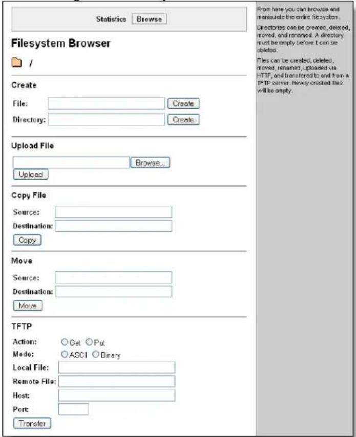
-
Click a filename to view the contents.
-
Click the X next to a filename to delete the file or directory. You can only delete a directory if it is empty.
- Enter or modify the following settings:
Note: Changes apply to the current directory view. To make changes within other folders, click the folder or directory and then enter the parameters in the settings listed below.
| File system Browser Page Settings | Description |
| Create | |
| File | Enter the name of the file you want to create, and then click Create. |
| Directory | Enter the name of the directory you want to create, and then click Create. |
| Upload File | Enter the path and name of the file you want to upload by means of HTTP(S) or use the Browse button to select the file, and then click Upload. |
| Copy File | |
| Source | Enter the location where the file you want to copy resides. |
| Destination | Enter the location where you want the file copied.After you specify a source and destination, click Copy to copy the file. |
| Move | |
| Source | Enter the location where the file you want to move resides. |
| Destination | Enter the location where you want the file moved.After you specify a source and destination, click Move to move the file. |
| TFTP | |
| Action | Select the action that is to be performed via TFTP:Get = a “get” command will be executed to store a file locally.Put = a “put” command will be executed to send a file to a remote location. |
| Mode | Select a TFTP mode to use. Choices are:ASCIIBinary |
| Local File | Enter the name of the local file on which the specified “get” or “put” action is to be performed. |
| Remote File | Enter the name of the file at the remote location that is to be stored locally (“get”) or externally (“put”). |
| Host | Enter the IP address or name of the host involved in this operation. |
| Port | Enter the number of the port involved in TFTP operations.Click Transfer to perform the TFTP transfer. |
Protocol Stack Configuration
Configure the EDS network stack protocols:
- Click Protocol Stack on the menu bar. The Protocol page appears with links to the TCP, IP, ICMP, and ARP protocols.
- Click on one of the protocol names to see the details of the settings for that protocol.
TCP Settings
Figure 12-3. TCP Protocol Page
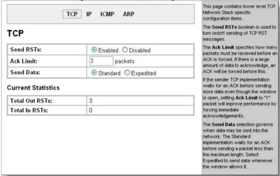
On the TCP page, you may modify the following settings:
Send RSTs:
TCP contains six control bits, with one or more defined in each packet. RST is one of the control bits. The RST bit is responsible for telling the receiving TCP stack to end a connection immediately.
CAUTION: Setting this flag may pose a security risk.
One Step Select Enabled to enable the sending of the RST flag.
One Step Select Disabled to disable the sending of the RST flag.
- Ack Limit:
The Ack Limit specifies how many packets must be received before an ACK is forced. If there is a large amount of data to acknowledge, an ACK will be forced before this.
If the sender TCP implementation waits for an ACK before sending more data even though the window is open, setting Ack Limit to "1" packet will improve performance by forcing immediate acknowledgements.
Send Data:
The Send Data selection governs when data may be sent into the network. The Standard implementation waits for an ACK before sending a packet less than the maximum length.
One Step Select Expedited to send data whenever the window allows it.
IP Setting
On the TCP page, you modify the Multicast Time to Live limit. The limit is the number of hops a packet may make before it is terminated
Figure 12-4. IP Protocol Page
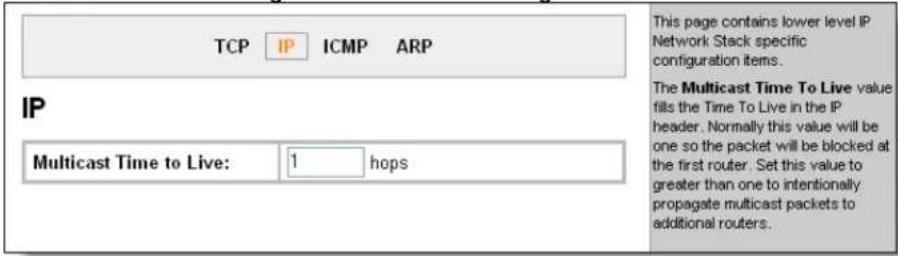
On the IP Protocol page, enter the number of hops a transmitted multicast packet may make before it is terminated.
ICMP Settings
On the ICMP page, you set enabled or disabled.
Figure 12-5. ICMP Protocol Page
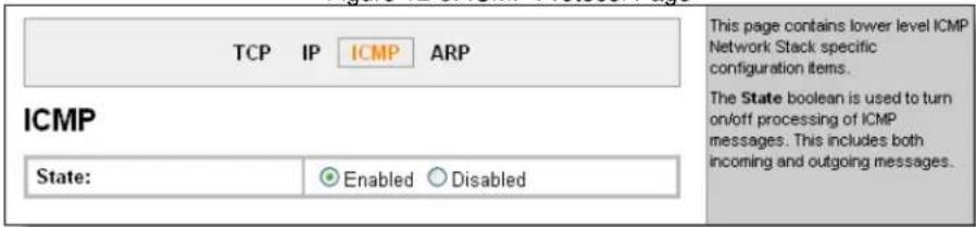
One Step Choose Enabled or Disabled.
ARP Settings
On the ARP page, you set the maximum time an address remains in the cache, and you specify both the IP and MAC addresses for the ARP cache. Both addresses are required.
Figure 12-6. ARP Protocol Page
![TCP IP ICMP ARP ARP ARP Timeout: 0 hours 1 minutes 0 seconds ARP Cache IP Address: MAC Address: Add Current State [ Remove All ] Address Age Sec MAC Address Type Interface 172.24.254.254 [Remove] 1.9 00:d0:04:02:c0:00 Dynamic 1 172.19.217.10 [Remove] 250.9 00:04:5a:59:ed:15 Dynamic 1 172.19.101.46 [Remove] 4.3 00:15:17:7b:c8:cb Dynamic 1 172.19.1.1 [Remove] 23.4 00:1b:21:0e:3d:f5 Dynamic 1 172.19.0.1 [Remove] 0.0 00:d0:04:02:c0:00 Dynamic 1 This page contains lower level ARP Network Stack specific configuration items. ARP The ARP Timeout specifies how long a MAC Address will remain in the cache before being removed. ARP Cache The ARP Cache can be manipulated manually by adding new entries and deleting existing ones.](/content/2026/05/1028534/images/8a620f7276fbd73529aecf9983fdeb2b137887e32a89aec80bb8277857f79e8e.jpg)
- Enter the time, in hours, minutes and seconds, for the timeout.
- Enter the IP address to add to the ARP cache.
- Enter the MAC address to add to the ARP cache.
- Click Add after supplying both fields.

Under Current State, select Remove All to remove all entries in the ARP cache, or select Remove to remove a specific entry from the ARP cache.
IP Address Filter
The IP address filter specifies the hosts and subnets permitted to communicate with the EDS.
Note: If using DHCP/BOOTP, ensure the DHCP/BOOTP server is in this list.
Configure the IP address filter:
- Click IP Address Filter on the menu bar. The IP Address Filter page opens to display the current configuration.
Figure 12-7. IP Address Filter Configuration
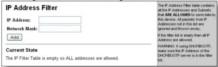
- Enter or modify the following settings:
| IP Address Filter Page Settings | Description |
| IP Address | Enter the IP address to add to the IP filter table. |
| Network Mask | Enter the IP address' network mask in dotted notation. |
-
In the Current State table, click Remove to delete settings as necessary.
-
Click Submit.
Query Port
The query port is used for the automatic discovery of the device by the DeviceInstaller utility. Only 0x77FE discover messages from DeviceInstaller are supported. For more information on DeviceInstaller, see Using DeviceInstaller on page 38.
Configure the query port server:
- Click Query Port on the menu bar. The Query Port page opens to display the current configuration.
Figure 12-8. Query Port Configuration
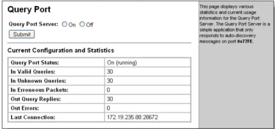
- Select On to enable the Query Port server.
- Click Submit.
Diagnostics
The EDS has several tools for diagnostics and statistics. The options at the top of the page allow for the configuration or viewing of MIB2 statistics, IP socket information, ping, traceroute, DNS lookup, memory, buffer pools, processes, and hardware.
Hardware
This read-only page shows the current hardware configuration.
Display the EDS hardware diagnostics:

Click Diagnostics on the menu bar. The Diagnostics: Hardware page opens and shows the current hardware configuration.
Figure 12-9. Diagnostics: Hardware
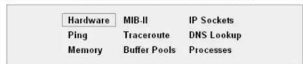
This page shows the basic hardware information for the device.
Diagnostics: Hardware
Current Configuration
| CPU Type: | IXP420 |
| CPU Speed: | 266.0 MHz |
| CPU Instruction Cache: | 32.000 Kbytes (32768 bytes) |
| CPU Data Cache: | 32.000 Kbytes (32768 bytes) |
| RAM Size: | 64.000000 Mbytes (67108864 bytes) |
| Flash Size: | 8.000000 Mbytes (8388608 bytes) |
| Flash Sector Size: | 128.000 Kbytes (131072 bytes) |
| Flash Sector Count: | 64 |
| Flash ID: | 0x89 |
MIB-II Statistics
The MIB-II Network Statistics page shows the various SNMP-served Management Information Bases (MIBs) available on the EDS.
View EDS MIB-II statistics:
- Click Diagnostics on the menu bar and then MIB-II at the top of the page menu. The MIB-II Network Statistics page opens.
Figure 12-10. MIB-II Network Statistics
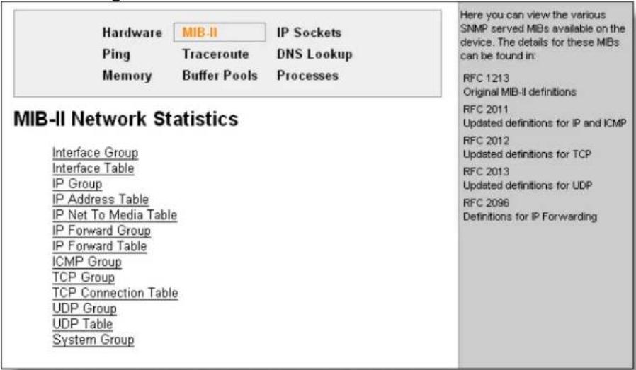
- Click any of the links to open the corresponding table and statistics.
For more information, refer to the following Requests for Comments (RFCs):
| RFC 1213 | Original MIB-II definitions. |
| RFC 2011 | Updated definitions for IP and ICMP. |
| RFC 2012 | Updated definitions for TCP. |
| RFC 2013 | Updated definitions for UDP. |
| RFC 2096 | Definitions for IP forwarding. |
IP Sockets
The IP Sockets page opens and shows all of the open network sockets on the EDS.
Display open network sockets on the EDS:
One Step Click Diagnostics on the menu bar and then IP Sockets.
Figure 12-11. IP Sockets
| Hardware MIB-II IP Sockets Ping Traceroute DNS Lookup Memory Buffer Pools Processes | |||||
| IP Sockets | |||||
| Protocol Rx0 Tx0 LocalAddr:Port RemoteAddr:Port State | |||||
| UDP | 0 | 0 | 172.19.101.78:161 | 255.255.255.255.0 | |
| TCP | 0 | 0 | 172.19.101.78:21 | 255.255.255.255.0 | LISTEN |
| TCP | 0 | 0 | 172.19.101.78:80 | 255.255.255.255.0 | LISTEN |
| UDP | 0 | 0 | 172.19.101.78:69 | 255.255.255.255.0 | |
| UDP | 0 | 0 | 172.19.101.78:30718 | 172.19.235.88:28672 | ESTABLISHED |
| TCP | 0 | 0 | 172.19.101.78:23 | 255.255.255.255.0 | LISTEN |
| TCP | 0 | 0 | 172.19.101.78:22 | 255.255.255.255.0 | LISTEN |
| TCP | 0 | 0 | 172.19.101.78:10001 | 255.255.255.255.0 | LISTEN |
| TCP | 0 | 0 | 172.19.101.78:10002 | 255.255.255.255.0 | LISTEN |
| TCP | 0 | 0 | 172.19.101.78:10003 | 255.255.255.255.0 | LISTEN |
| TCP | 0 | 0 | 172.19.101.78:10004 | 255.255.255.255.0 | LISTEN |
| TCP | 0 | 0 | 172.19.101.78:10005 | 255.255.255.255.0 | LISTEN |
| TCP | 0 | 0 | 172.19.101.78:10006 | 255.255.255.255.0 | LISTEN |
| TCP | 0 | 0 | 172.19.101.78:10007 | 255.255.255.255.0 | LISTEN |
| TCP | 0 | 0 | 172.19.101.78:10008 | 255.255.255.255.0 | LISTEN |
| TCP | 0 | 4 | 172.19.101 78:80 | 172.20.197 . 102 : 1474 | ESTABLISHED |
Ping
You can ping a remote device or computer from your EDS.
Ping a remote device or computer:
- Click Diagnostics on the menu bar then click Ping. The Ping page appears.
Figure 12-12. Diagnostics: Ping
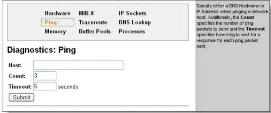
- Enter or modify the following settings:
| Diagnostics: Ping Page Settings | Description |
| Host | Enter the IP address or host name to ping. |
| Count | Enter the number of ping packets to send to the Host. The default is 3. |
| Timeout | Enter the time, in seconds, to wait for a response from the host before timing out. The default is 5 seconds. |
- Click Submit. The results of the ping appear in the page.
Traceroute
You can trace a packet from the EDS to an Internet host, showing how many hops the packet requires to reach the host and how long each hop takes.
If you visit a web site whose pages appear slowly, you can use traceroute to determine where the longest delays are occurring.
Use Traceroute from the EDS:
- Click Diagnostics on the menu bar then Traceroute at the top of the page. The Traceroute page appears.
Figure 12-13. Diagnostics: Traceroute
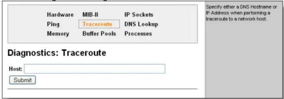
-
Enter or modify the IP address or DNS hostname.
-
Click Submit. The results of the traceroute appear in the page.
DNS Lookup
You can specify a DNS Hostname for a forward lookup or an IP address for a reverse lookup.
You can also perform a lookup for a Mail (MX) record by prefixing a DNS Hostname with @.
Note: A DNS server must be configured for DNS Lookup to work.
Use forward or reverse DNS lookup:
- Click Diagnostics on the menu bar then DNS Lookup at the top of the page. The Diagnostics: DNS Lookup page appears.
Figure 12-14. Diagnostics: DNS Lookup
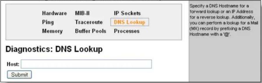
- Enter or modify the following field:
| DNS Lookup Page Setting | Description |
| Host | For reverse lookup to locate the hostname for that IP address, enter an IP address.For forward lookup to locate the corresponding IP address, enter a hostname.To look up the Mail Exchange (MX) record IP address, enter a domain name prefixed with @. |
- Click Submit. The results of the lookup appear in the page.
Memory
This read-only page shows the total memory and available memory (in bytes), along with the number of fragments, allocated blocks, and memory status.
Display memory statistics for the EDS:

Click Diagnostics on the menu bar then Memory at the top of the page. The Diagnostics: Memory page appears.
Figure 12-15. Diagnostics: Memory
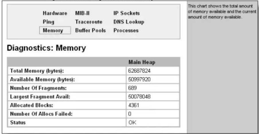
Buffer Pools
Several parts of the EDS system use private buffer pools to ensure deterministic memory management.
Display the EDS buffer pools:

Click Diagnostics on the menu bar then Buffer Pools at the top of the page. The Diagnostics: Buffer Pools page appears.
Figure 12-16. Diagnostics: Buffer Pools
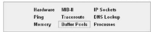
Diagnostics: Buffer pools
| Network Stack Buffer Pool | ||||
| Total | Free | Used | MaxUsed | |
| Buffer Headers | 4096 | 4094 | 2 | 17 |
| Cluster Pool Size: 2048 | 2048 | 2048 | 2 | 10 |
| Ethernet Driver Buffer Pool | ||||
| Total | Free | Used | MaxUsed | |
| Buffer Headers | 4096 | 3640 | 256 | 296 |
| Cluster Pool Size: 2112 | 2048 | 1792 | 256 | 296 |
| Serial Driver Line 1 Buffer Pool | ||||
| Total | Free | Used | MaxUsed | |
| Buffer Headers | 64 | 32 | 32 | 32 |
| Cluster Pool Size: 2048 | 32 | 0 | 32 | 32 |
| Serial Driver Line 2 Buffer Pool | ||||
| Total | Free | Used | MaxUsed | |
| Buffer Headers | 64 | 32 | 32 | 32 |
| Cluster Pool Size: 2018 | 32 | 0 | 32 | 32 |
| Serial Driver Line 3 Buffer Pool | ||||
| Total | Free | Used | MaxUsed | |
| Buffer Headers | 64 | 32 | 32 | 32 |
| Cluster Pool Size: 2018 | 32 | 0 | 32 | 32 |
| Serial Driver Line 4 Buffer Pool | ||||
| Total | Free | Used | MaxUsed | |
| Buffer Headers | 64 | 32 | 32 | 32 |
| Cluster Pool Size: 2018 | 32 | 0 | 32 | 32 |
| Serial Driver Line 5 Buffer Pool | ||||
| Total | Free | Used | MaxUsed | |
| Buffer Headers | 64 | 32 | 32 | 32 |
| Cluster Pool Size: 2048 | 32 | 0 | 32 | 32 |
| Serial Driver Line 6 Buffer Pool | ||||
| Total | Free | Used | MaxUsed | |
| Buffer Headers | 64 | 32 | 32 | 32 |
| Cluster Pool Size: 2048 | 32 | 0 | 32 | 32 |
| Serial Driver Line 7 Buffer Pool | ||||
| Total | Free | Used | MaxUsed | |
| Buffer Headers | 64 | 32 | 32 | 32 |
| Cluster Pool Size: 2018 | 32 | 0 | 32 | 32 |
| Serial Driver Line 8 Buffer Pool | ||||
| Total | Free | Used | MaxUsed | |
| Buffer Headers | 64 | 32 | 32 | 32 |
| Cluster Pool Size: 2048 | 32 | 0 | 32 | 32 |
| Serial Driver Line 9 Buffer Pool | ||||
| Total | Free | Used | MaxUsed | |
| Buffer Headers | 64 | 32 | 32 | 32 |
| Cluster Pool Size: 2048 | 32 | 0 | 32 | 32 |
These charts show the current usage of the private buffer pools. Private buffer pools are used in various parts of the system to ensure deterministic memory management thus eliminating any contention for memory from the generic heap space.
Processes
The EDS Processes page shows all the processes currently running on the system.
It shows the Process ID (PID), the percentage of total CPU cycles a process used within the last three seconds, the total stack space available, the maximum amount of stack space used by the process since it started, and the process name.
Display the processes running on the EDS:

Click Diagnostics on the menu bar then Processes at the top of the page.
Figure 12-17. Diagnostics: Processes
| PID | CPU % | Stacks | Process Name |
| 2 | 92.78% | 744/2048 | Idle Task |
| 3 | 0.70% | 746/1504 | RTC |
| 4 | 5.47% | 544/2048 | Timeout Server |
| 5 | 0.53% | 932/3072 | Event Server |
| 6 | 0.00% | 366/2048 | DNS Cache |
| 7 | 0.00% | 1264/4096 | EthDB event thread |
| 8 | 0.00% | 544/16192 | EthDB maintainer |
| 9 | 0.00% | 772/2048 | Ethernet Manager |
| 10 | 0.00% | 948/2112 | Snmp Agent |
| 11 | 0.00% | 2632/6144 | Dynamic IP Daemon (eth0) |
| 12 | 0.00% | 752/2048 | FTP Server |
| 13 | 0.00% | 860/3072 | TFTP Server |
| 14 | 0.00% | 2820/24576 | Http1 |
| 15 | 0.00% | 2860/24576 | Http2 |
| 16 | 0.10% | 5712/24576 | Http3 |
| 17 | 0.00% | 848/32768 | Http0 |
| 18 | 0.00% | 988/2400 | Query Port (77FE) |
| 19 | 0.00% | 384/16384 | Network->Serial Daemon Port 1 |
| 20 | 0.00% | 596/16384 | Serial->Network Daemon Port 1 |
| 21 | 0.01% | 1052/49152 | Accept Mode Daemon Port 1 |
| 22 | 0.00% | 520/49152 | Connect Mode Daemon Port 1 |
| 23 | 0.00% | 384/16384 | Network->Serial Daemon Port 2 |
| 24 | 0.00% | 596/16384 | Serial->Network Daemon Port 2 |
| 25 | 0.01% | 1052/49152 | Accept Mode Daemon Port 2 |
| 26 | 0.00% | 520/49152 | Connect Mode Daemon Port 2 |
| 27 | 0.00% | 384/16384 | Network->Serial Daemon Port 3 |
| 28 | 0.00% | 596/16384 | Serial->Network Daemon Port 3 |
| 29 | 0.01% | 1232/49152 | Accept Mode Daemon Port 3 |
| 30 | 0.00% | 520/49152 | Connect Mode Daemon Port 3 |
| 31 | 0.00% | 384/16384 | Network->Serial Daemon Port 4 |
| 32 | 0.00% | 648/16384 | Serial->Network Daemon Port 4 |
| 33 | 0.01% | 1232/49152 | Accept Mode Daemon Port 4 |
| 34 | 0.00% | 520/49152 | Connect Mode Daemon Port 4 |
| 35 | 0.00% | 384/16384 | Network->Serial Daemon Port 5 |
| 36 | 0.00% | 596/16384 | Serial->Network Daemon Port 5 |
| 37 | 0.01% | 992/49152 | Accept Mode Daemon Port 5 |
| 38 | 0.00% | 520/49152 | Connect Mode Daemon Port 5 |
| 39 | 0.00% | 384/16384 | Network->Serial Daemon Port 6 |
| 40 | 0.00% | 596/16384 | Serial->Network Daemon Port 6 |
| 41 | 0.01% | 992/49152 | Accept Mode Daemon Port 6 |
| 42 | 0.00% | 520/49152 | Connect Mode Daemon Port 6 |
| 43 | 0.00% | 384/16384 | Network->Serial Daemon Port 7 |
| 44 | 0.00% | 596/16384 | Serial->Network Daemon Port 7 |
| 45 | 0.01% | 1232/49152 | Accept Mode Daemon Port 7 |
| 46 | 0.00% | 520/49152 | Connect Mode Daemon Port 7 |
| 47 | 0.00% | 384/16384 | Network->Serial Daemon Port 8 |
| 48 | 0.00% | 596/16384 | Serial->Network Daemon Port 8 |
| 49 | 0.01% | 1232/49152 | Accept Mode Daemon Port 8 |
| 50 | 0.00% | 520/49152 | Connect Mode Daemon Port 8 |
| 51 | 0.00% | 3032/6192 | SMTP Client |
| 52 | 0.00% | 748/3072 | Telnet Server |
| 53 | 0.00% | 748/3072 | SSH Server |
| 54 | 0.00% | 496/24576 | Serial Command Interpreter Port 1 |
| 55 | 0.00% | 496/24576 | Serial Command Interpreter Port 2 |
| 56 | 0.00% | 496/24576 | Serial Command Interpreter Port 3 |
| 57 | 0.00% | 496/24576 | Serial Command Interpreter Port 4 |
| 58 | 0.00% | 496/24576 | Serial Command Interpreter Port 5 |
| 59 | 0.00% | 496/24576 | Serial Command Interpreter Port 6 |
| 60 | 0.00% | 496/24576 | Serial Command Interpreter Port 7 |
| 61 | 0.00% | 496/24576 | Serial Command Interpreter Port 8 |
| 62 | 0.19% | 1372/24576 | Serial Command Interpreter Port 9 |
| 72 | 0.00% | 860/5120 | LPD Daemon |

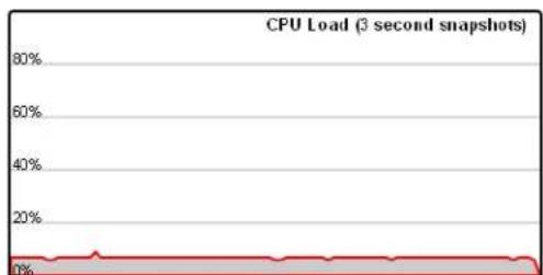
line
| Time | CPU Load | | ---- | -------- | | 0 | 0% | | 10 | ~5% | | 20 | ~5% | | 30 | ~5% | | 40 | ~5% | | 50 | ~5% | | 60 | ~5% | | 70 | ~5% | | 80 | ~5% |SVG plugin required to view graph.
Note: The Adobe SVG plug-in is required to view the CPU Load Graph.
Real Time Clock Page
You can view or change the current date or time configured on the EDS.
Figure 12:-18. Real Time Clock Page
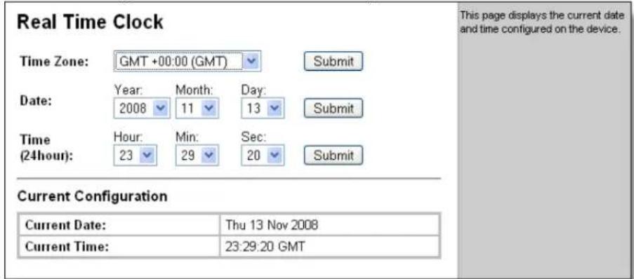
Real Time Clock Page settings
- Modify the following settings to set change the current date and time:
| Real TimeClock PageSettings | Description |
| Time Zone From the drop-down list, select the time zone corresponding tothe location of the EDS. | |
| Date From the drop-down lists, select the year, month, and daycorresponding to the current date at the location of the EDS. | |
| Time (24 hour) From the drop-down list, select the hour, minutes, and secondscorresponding to the current time at the location of the EDS. | |
- Click Submit.
System Configuration
You can reboot the device, restore factory defaults, upload new firmware, configure the short and long name, and view the current system configuration.
Configure the EDS system settings:
- Click System on the menu bar. The System page appears.
Figure 12-19. System Page
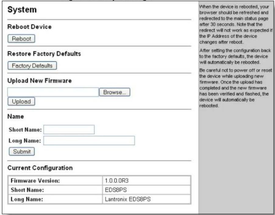
- Configure the following settings:
| System Page Settings | Description |
| Reboot Device | Click Reboot to reboot the EDS. The system refreshes and redirects the browser to the EDS home page. |
| Restore Factory Defaults | Click Factory Defaults to restore the EDS to the original factory settings. All configurations will be lost. The EDS automatically reboots upon setting back to the defaults. |
| Upload New Firmware | Click Browse to locate the firmware file location. Click Upload to install the firmware on the EDS. The device automatically reboots upon the installation of new firmware. |
| Name | Enter a new Short Name and a Long Name (if necessary).The Short Name maximum is 32 characters. The Long Name maximum is 64 characters. Changes take place upon the next reboot. |
13: Advanced Settings
This chapter presents information for advanced activities, modes, and statistics.
- Email alerts.
- CLI settings.
■ CLI servers on Telnet and SSH ports. - Export or import an EDS configuration files.
- Accept Mode.
Connect Mode. - Disconnect Mode.
- Packing Mode.
■ Modem Emulation mode.
Serial Line Settings.
■ Tunneling Statistics.
Email Configuration
You can view and configure email alerts from the EDS. This section tells you how to configure alerts. See Configure Accept Mode on page 58, and Configure Connect Mode on page 64, for how to set the triggers for the alerts.
Email Statistics
When the EDS transmits an email, the entire conversation with the SMTP server is logged and shown in the bottom portion of the EDS Statistics page.
This page shows statistics and usage information about the email subsystem.
View email statistics.

Click Email from the main menu, then choose an email profile, from the drop down list, e.g. Email 1, then click Statistics.
Figure 13-1. Email Statistics
![Select Email: Email 1 Statistics Configuration Send Email Email 1 - Statistics Sent successfully (w/retries): 8/0 Not sent due to excessive errors: 1 In transmission queue: 0 Log [Clear] No log data available.](/content/2026/05/1028534/images/edf1496ce87d911ea6f16865800106c4c2adcff2f35f95fb6f90f6082d427c39.jpg)

To clear the log, click Clear.
Email Configuration
You can set up to 8 email profiles. Each profile can have multiple email addresses or email address groups, separated by semicolons.
Configure EDS email settings:
- Click Email on the menu bar and then Email n and Configuration at the top of the page. The Email 1 - Configuration page appears.
Figure 13-2. Email Configuration
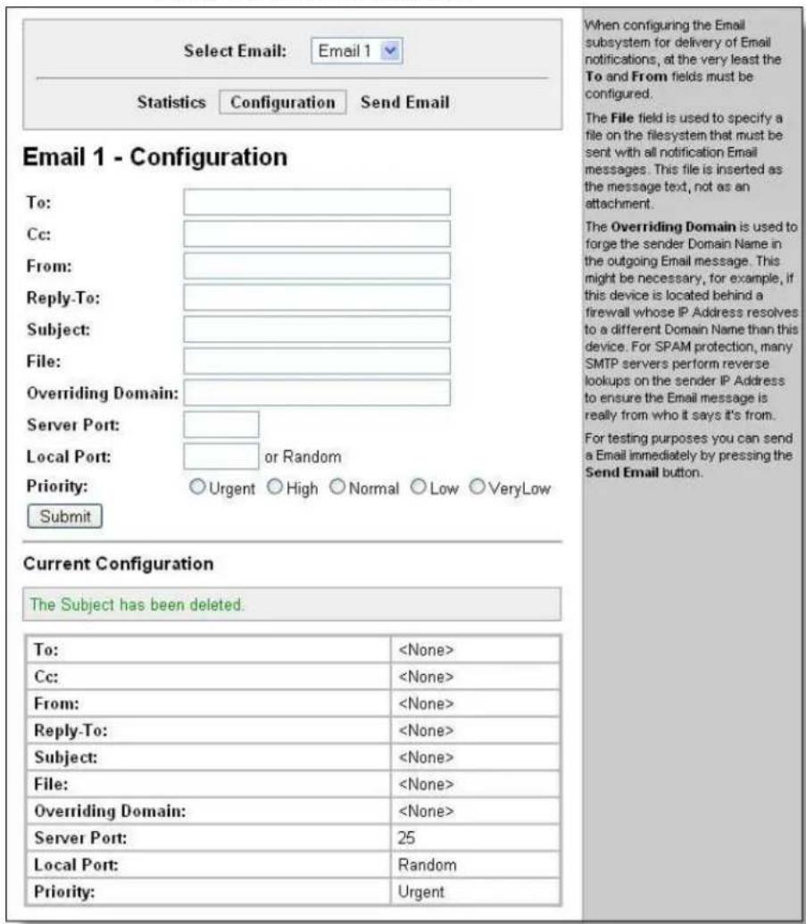
- Enter or modify any of the settings.
- Click Submit.
- In the Current Configuration table, delete currently stored settings as necessary.
To test your configuration, you can send an email immediately by clicking Send Email at the top of the page. Refer to the Statistics page for a log of the transaction.
Command Line Interface Settings
The Command Line Interface pages enable you to view statistics about the CLI servers listening on the Telnet and SSH ports, and to configure CLI settings.
Command Line Interface Statistics
This shows the current connection status of the CLI servers listening on the Telnet and SSH ports.
When a connection is active:
■ The remote client information appears.
■ The number of bytes that have been sent and received appears.
A Kill link (visible when a connection is active) can be used to terminate the connection.
View command line interface statistics:
Click CLI on the menu bar. The Command Line Interface Statistics page appears.
Figure 13-3. Command Line Interface Statistics
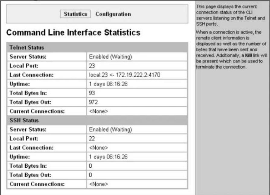
CLI Configuration
On this page you can change CLI configuration settings.
Configure the CLI:
- Click CLI on the menu then Configuration at the top of the page. The Command Line Interface Configuration page appears.
Figure 13-4. Command Line Interface Configuration
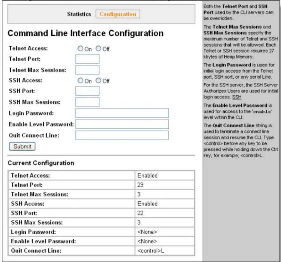
- Enter or modify the following settings:
| Command Line InterfaceConfiguration Settings | Description |
| Telnet Access Select | On to enable Telnet access. Telnet is enabled by default. |
| Telnet Port | Enter the Telnet port to use for Telnet access. The default is 23. |
| Telnet MaxSessions | Maximum number of simultaneous Telnet sessions. |
| SSH Access Select On to enable SSH access. SSH is enabled by default. | |
| SSH Port | Enter the SSH port to use for SSH access. The default is 22. |
| SSH Max Sessions | Maximum number of simultaneous SSH sessions. |
| Login Password | Enter the password for Telnet access. |
| Enable Level Password | Enter the password for access to the Command Mode Enable level. There is no password by default. |
| Quit connect line | Enter a string to terminate a connect line session and resume the CLI. Typebefore any key the user must press when holding down the Ctrl key. An example of such a string isL. |
3. Click Submit.
XML Configuration
The EDS allows for the configuration of units using an XML configuration file. Export a current configuration for use on other EDSs or import a saved configuration file.
XML: Export Configuration
On this page you can export the current system configuration in XML format. The generated XML file can be imported later to restore a configuration. It can also be modified and imported to update the configuration on this EDS unit or another. The XML data can be exported to the browser window or to a file on the file system.
By default, all groups are selected except those pertaining to the network configuration. This is so that if you later import the entire XML configuration, it will not break your network connectivity. You may select or clear the checkbox for any group.
Export a system configuration record:
- Click XML on the menu bar then Export Configuration at the top of the page.
Figure 13-5. XML: Export Configuration
![Export Configuration Export Status Import Configuration XML: Export Configuration ○ Export to browser ○ Export to local file □ Export secrets (use only with extreme caution) Lines to Export: [Clear All] [Select All] ✓ 1 ✓ 2 ✓ 3 ✓ 4 ✓ 5 ✓ 6 ✓ 7 ✓ 8 ✓ 9 ✓ network Groups to Export: [Clear All] [Select All but Networking] ✓ arp ✓ cli ✓ clock ✓ device ✓ email □ ethernet: eth0 ✓ ftp server ✓ host ✓ http authentication uri ✓ http server ✓ icmp □ interface: eth0 ✓ ip ✓ ip filter ✓ line ✓ lpd ✓ query port ✓ rss ✓ serial command mode ✓ snmp ✓ ssh client ✓ ssh command mode ✓ ssh server ✓ ssl ✓ syslog ✓ tcp ✓ telnet command mode ✓ terminal ✓ tftp server ✓ tunnel accept ✓ tunnel connect ✓ tunnel disconnect ✓ tunnel modem ✓ tunnel packing ✓ tunnel serial ✓ tunnel start ✓ tunnel stop ✓ xml import control Export This page is used for exporting the current system configuration in XML format as XCR records. The generated XML file can be imported at a later time to restore the configuration. Also, the XML file can be modified and imported to update the configuration on this device or another. The XML data can be exported to the browser window or to a file on the filesystem. Caution: only export secrets over a secure connection and make sure that the data goes only to secure locations. Notice that by default, all Groups to Export are checked except those pertaining to the network configuration; this is so that if you later "paste" the entire XML configuration, it will not break your network connectivity. You may check or uncheck any group to include or omit that group from export. Selection of Lines to Export filters instances to be exported in the line, lpd, serial, tunnel ..., and terminal groups.](/content/2026/05/1028534/images/9c759444a0d51c64e1548c9e49090a393a2e8d018de929850569fa236ba36571.jpg)
- Enter or modify the following settings:
| XML ExportConfiguration PageSettings | Description |
| Export to browser | Select this option to export the XCR data in the selected fields to a web browser. |
| Export to local file | Select this option to export the XCR data to a file on the device. If you select this option, enter a file name for the XML configuration record. |
| Export secrets | Only use this with extreme caution. If selected, secret password and key information will be exported. Use only with a secure link, and save only in secure locations. |
| Lines to Export | Select the instances you want to export in the line, LPD, PPP, tunnel, and terminal groups. |
| Groups to Export | Check the configuration groups that are to be exported to the XML configuration record. |
3. Click Export.
The groups appear if exporting the data to the browser. If exporting to the file system, the file is stored on the file system.
XML: Export Status
You can export the current system status in XML format to a web browser or to a file on the file system.
- Click XML on menu bar and then Export Status at the top of the page. The XML Status Record: Export Status page appears.
Figure 13-6. XML Status Record: Export Status
![Export Configuration Export Status Import Configuration XML: Export Status ○ Export to browser ○ Export to local file Lines to Export: [Clear All] [Select All] ✓ 1 ✓ 2 ✓ 3 ✓ 4 ✓ 5 ✓ 6 ✓ 7 ✓ 8 ✓ 9 ✓ network Groups to Export: [Clear All] [Select All] ✓ arp buffer pool ✓ clock device ✓ email email log ✓ filesystem ftp ✓ hardware http ✓ http log icmp ✓ interface: eth0 ip ✓ ip sockets line ✓ lpd memory ✓ processes query port ✓ rss sessions ✓ ssh syslog ✓ tcp telnet ✓ tftp tunnel ✓ udp xsr Export](/content/2026/05/1028534/images/2fe0f1eebad94e4733aec7038acbfe8b7ec70ded4b00f505cb65d8d56e22b4ef.jpg)
- Enter or modify the following settings:
| XML Status Record: Export System Status Page Settings | Description |
| Export to browser | Select this option to export the XML status record to a web browser. |
| Export to local file | Select this option to export the XML status record to a file on the device. If you select this option, enter a file name for the XML status record. |
| Lines to Export | Select the instances you want to export in the line, LPD, PPP, tunnel, and terminal groups. |
| Groups to Export | Check the configuration groups that are to be exported into the XML status record. |
3. Click the Export button.
The groups display if exporting the data to the browser. If exporting to the file system, the file is stored on the file system.
XML: Import System Configuration Page
You can also import a system configuration from an XML file.
The XML data can be imported from a file on the file system or uploaded using HTTP. The groups to import can be specified by toggling the respective group item or entering a filter string. When toggling a group item, all instances of that group will be imported. The filter string can be used to import specific instances of a group. The text format of this string is:
$$ < g >: < i >; < g >: < i >; \dots $$
Each group name
Import a system configuration:
- Click XML on the menu bar and then Import Configuration at the top of the page. The XML: Import Configuration page appears.
Figure 13-7. XML: Import Configuration
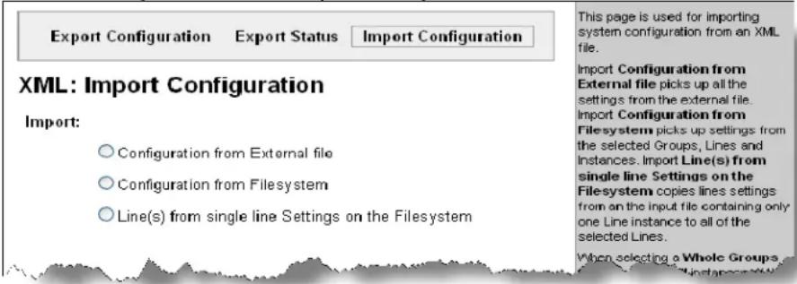
- Click one of the radio buttons to select the type of source to import from.
Import Configuration from External File
This selection shows a field for entering the path and file name of the entire external XCR file to import. You can also browse to select the XCR file.
Figure 13-8. XML: Import Configuration from External File
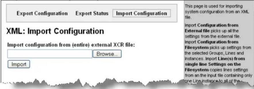
Import Configuration from the Filesystem
This selection shows a page for entering the file system and your import requirements – groups, lines, and instances.
Figure 13-9. XML: Import from Filesystem
![Export Configuration Export Status.Import Configuration XML: Import Configuration Import Line(s) from single line settings on the filesystem: Filename: Lines to Import: [Clear All] [Select All] ✓ 1 ✓ 2 ✓ 3 ✓ 4 ✓ 5 ✓ 6 ✓ 7 ✓ 8 ✓ 9 ✓ network Whole Groups to Import: [Clear All] [Select All but Networking] ✓ arp ✓ cli ✓ clock ✓ device ✓ email □ ethernet ✓ execute ✓ exit cli ✓ ftp server ✓ host ✓ http authentication uri ✓ http server ✓ icmp □ interface ✓ ip ✓ ip filter ✓ line ✓ lpd ✓ query port ✓ rss ✓ serial command mode ✓ snmp ✓ ssh client ✓ ssh command mode ✓ ssh server ✓ ssl ✓ syslog ✓ tcp ✓ telnet command mode ✓ terminal ✓ tftp server ✓ tunnel accept ✓ tunnel connect ✓ tunnel disconnect ✓ tunnel modem ✓ tunnel packing ✓ tunnel serial ✓ tunnel start ✓ tunnel stop ✓ xml import control Import This page is used for importing system configuration from an XML file. Import Configuration from External file picks up all the settings from the external file. Import Configuration from Filesystem picks up settings from the selected Groups, Lines and Instances. Import Line(s) from single line Settings on the Filesystem copies lines settings from an the input file containing only one Line instance to all of the selected Lines. When selecting a Whole Groups to Import item, all instances of that group will be imported. Notice that by default, all groups are checked except those pertaining to the network configuration; this is so that import will not break your network connectivity. You may check or uncheck any group to include or omit that group from import. Selection of Lines to Import filters instances to be imported in the line, lpd, serial, tunnel ..., and terminal groups. This affects both Whole Groups to Import and Text List selections. Use the Text List string to import specific instances of a group. The textual format of this string is: : ; : ; ... Each group name is followed by a colon and the instance value and each value is separated by a semi-colon. If a group has no instance then only the group name should be specified.](/content/2026/05/1028534/images/5d442bd66925d3feeacfcbc1e3143fd4a105bfc7da03192568a4e2e8e0c5908d.jpg)
- Enter the filename of the XCR file with the groups to import.
- Enter or modify the following settings:
| ImportConfigurationfrom File systemSettings | Description |
| Filename | Enter the name of the file on the EDS (local to its file system) that contains XCR data. |
| Lines to Import | Select the lines whose settings you want to import. Click the Select All link to select all the serial lines and the network lines. Click the Clear All link to clear all of the checkboxes. By default, all line instances are selected.Only the selected line instances will be imported in the line, LPD, PPP, tunnel, and terminal groups. |
| Whole Groups to Import | Select the configuration groups to import from the XML configuration record. This option imports all instances of each selected group unless it is one of the Lines to Import.Note: By default, all groups are checked except those pertaining to the network configuration; this is so that import will not break your network connectivity.You may check or uncheck any group to include or omit that group from import. To import all of the groups, click the Select All but Networking link to import all groups. To clear all the checkboxes, click the Clear All link. |
| Text List | Enter a string to import specific instances of a group. The textual format of this string is::;...Each group nameis followed by a colon and the instance valueand eachvalue is separated by a semi-colon. If a group has no instance, then specify the group nameonly.Use this option for groups other than those affected by Lines to Import. |
Import Line(s) from Single Line Settings on the File system
This selection copies line settings from the single line instance in the input file to selected lines. The import file may only contain records from a single line instance; this is done by selecting a single Line to Export when exporting the file.
Figure 13-10. XML: Import Line(s) from Single Line Settings on the File system
![Export Configuration Export Status.Import Configuration XML: Import Configuration Import Line(s) from single line settings on the filesystem: Filename: Lines to Import: [Clear All] [Select All] ✓ 1 ✓ 2 ✓ 3 ✓ 4 ✓ 5 ✓ 6 ✓ 7 ✓ 8 ✓ 9 ✓ network Whole Groups to Import: [Clear All] [Select All but Networking] ✓ arp ✓ cli ✓ clock ✓ device ✓ email □ ethernet ✓ execute ✓ exit cli ✓ ftp server ✓ host ✓ http authentication uri ✓ http server ✓ icmp □ interface ✓ ip ✓ ip filter ✓ line ✓ lpd ✓ query port ✓ rss ✓ serial command mode ✓ snmp ✓ ssh client ✓ ssh command mode ✓ ssh server ✓ ssl ✓ syslog ✓ tcp ✓ telnet command mode ✓ terminal ✓ tftp server ✓ tunnel accept ✓ tunnel connect ✓ tunnel disconnect ✓ tunnel modem ✓ tunnel packing ✓ tunnel serial ✓ tunnel start ✓ tunnel stop ✓ xml import control Import This page is used for importing system configuration from an XML file. Import Configuration from External file picks up all the settings from the external file. Import Configuration from Filesystem picks up settings from the selected Groups, Lines and Instances. Import Line(s) from single line Settings on the Filesystem copies lines settings from an the input file containing only one Line instance to all of the selected Lines. When selecting a Whole Groups to Import item, all instances of that group will be imported. Notice that by default, all groups are checked except those pertaining to the network configuration; this is so that import will not break your network connectivity. You may check or uncheck any group to include or omit that group from import. Selection of Lines to Import filters instances to be imported in the line, lpd, serial, tunnel ..., and terminal groups. This affects both Whole Groups to Import and Text List selections. Use the Text List string to import specific instances of a group. The textual format of this string is: < g> : < i > ; < g> : < i > ; ... Each group name < g> is followed by a colon and the instance value < i> and each < g> < i> value is separated by a semi-colon. If a group has no instance then only the group name < g> should be specified.](/content/2026/05/1028534/images/ae46b1f82981563a5ea7482a08cf8cb11375f36a658db45faf061133767a983e.jpg)
XML: Import Lines from Single Line(s) Settings
- Enter or modify the following settings:
| Import Line(s) Settings | Description |
| Filename | Enter the name of the file on the EDS (local to its file system) that contains XCR data. |
| Lines to Import | Select the line(s) of settings to import.Click the Select All link to select all the serial lines and the network lines.Click the Clear All link clear all of the checkboxes.By default, all serial line instances are selected. |
| Whole Groups to Import | Select the configuration groups to import from the XML configuration record.Note: By default, all groups are checked except those pertaining to the network configuration; this is so that the import will not break your network connectivity.You may check or uncheck any group to include or omit that group from import.To import all of the groups, click the Select All but Networking link to import all groups.To clear all the checkboxes, click the Clear All link. |
14: Tunneling
Tunneling allows serial devices to communicate over a network, without "being aware" of the devices which establish the network connection between them.
Tunneling parameters are configured as described in Tunnel Settings, on page 57—or via the Command Mode Tunnel Menu (see the EDS Command Reference for the full list of commands.)
The EDS supports two tunneling connections simultaneously per serial port. One of these connections is Connect Mode; the other connection is Accept Mode. The connections on one serial port are separate from those on another serial port.
Connect Mode: The EDS actively makes a connection. The receiving node on the network must listen for the Connect Mode's connection. Connect Mode is disabled by default.
Accept Mode: The EDS listens for a connection. A node on the network initiates the connection. Accept Mode is enabled by default.
- Disconnect Mode: This mode defines how an open connection stops the forwarding of data. The specific parameters to stop the connection are configurable. Once the EDS Disconnect Mode observes the defined event occur, it will disconnect both Accept Mode and Connect Mode connections on that port.
When any character comes in through the serial port, it gets copied to both the Connect Mode connection and the Accept Mode connection (if both are active).
Connect Mode
For Connect Mode to function, it must be enabled, have a remote station (node) configured, and a remote port configured (TCP or UDP). When enabled, Connect Mode is always on.
Enter the remote station as an IP address or DNS name. The EDS will not make a connection unless it can resolve the address. For DNS names, after 4 hours of an active connection, the EDS will re-evaluate the address. If it is a different address, it will close the connection.
Connect Mode supports the following protocols:
■ AES over TCP and UDP
■ SSH (the EDS is the SSH client)
SSL
TCP
Telnet
■ UDP (Connect Mode only)
When setting AES encryption, both the encrypt key and the decrypt key must be specified. The encrypt key is used for data sent out. The decrypt key is used for receiving data. Both of the keys may be set to the same value.
For Connect Mode using UDP, the EDS accepts packets from any device on the network. It will send packets to the last device that sent it packets.
Note: The Local Port in Connect Mode is not the same port configured in Accept Mode.
To ignore data sent to the EDS, enable the blocking of serial data or network data (or both).
The TCP keepalive time is the time in which probes are periodically sent to the other end of the connection. This ensures the other side is still connected.
To configure SSH, the SSH client username must be configured.
In Connect Mode, the EDS is the SSH client. Ensure the EDS SSH client username is configured on the remote SSH server before using it with the EDS.
Connect Mode has six states:
■ Disabled (no connection)
■ Enabled (always makes a connection)
■ Active if it sees any character from the serial port
■ Active if it sees a specific (configurable) character from the serial port
■ Modem control signal
Modem emulation
For the “any character” or “specific character” connection states, the EDS waits and retries the connection if the connection cannot be made. Once it makes a connection and then disconnects, it will not reconnect until it sees any character or the start character again (depending on the configured setting).
Configure the Modem Control Asserted setting (for DSR or DTR) to start a Connect Mode connection when the signal is asserted. The EDS will try to make a connection indefinitely. If the connection closes, it will not make another connection unless the signal is asserted again.
Accept Mode
In Accept Mode, the EDS waits for a connection from the network. The configurable local port is the port the remote device connects to for this connection. There is no remote port or address. The default local port is 10001 for serial port 1 and 10002 for serial port 2.
Accept Mode supports the following protocols:
■ SSH (the EDS is the server in Accept Mode). When using this protocol, the SSH server host keys and at least one SSH authorized user must be configured.
SSL
TCP
■ AES encryption over TCP
Telnet (The EDS supports IAC codes. It drops the IAC codes when Telneting and does not forward them to the serial port).
Accept Mode has the following states:
■ Disabled (never a connection)
■ Enabled (always listening for a connection)
■ Active if it receives any character from the serial port
Active if it receives a specific (configurable) character from the serial port (same start character as Connect Mode's start character)
■ Modem control signal
Modem emulation
Disconnect Mode
Disconnect Mode ends Accept Mode and Connect Mode connections. When disconnecting, the EDS shuts down connections gracefully.
The following settings end a connection:
■ The EDS receives the stop character.
The timeout period has elapsed and no activity is going in or out of the EDS. Both Accept Mode and Connect Mode must be idle for the time frame.
■ The EDS observes the modem control inactive setting.
Note: To clear data from serial buffers on disconnect, enable "Flush Serial Data".
Packing Mode
Packing Mode takes data from the serial port, groups it together, and sends it out to nodes on the network. The groupings may be configured by size or by time intervals.
The following settings are configurable for Packing Mode:
■ Disabled
- Timeout: The data is packed for a specified period before being sent out. Specifies the time duration in milliseconds; applies only if the Packing Mode is Timeout.
- Threshold: When the buffer fills to this specified amount of data in bytes (and the timeout has not elapsed), the EDS packs the data and sends it out; applies only if the Packing Mode is not Disabled.
- Send Character: The data is packed until the specified send character is encountered. Similar to a start or stop character, the EDS packs the data until it sees the send character. The EDS then sends the packed data and the send character in the packet. Applies only if the Packing Mode is Send Character.
- Trailing Character: If a trailing character is defined, this character is appended to data put on the network immediately following the send character.
Modem Emulation
The EDS supports Modem Emulation mode for devices that send out modem signals. There are two different modes supported:
Command Mode: sends back verbal response codes.
Data Mode: information transferred in is also transferred out.
You can change the default settings for verbose response codes, echo commands, and quiet mode, by using Command Mode commands. The current settings can be overridden; however on reboot, it will go back to the programmed settings.

Configure the connect string as necessary. The connect string appends to the communication packet when the modem connects to a remote location. You can append additional text to the connect message.
Command Mode
The Modem Emulation Command Mode supports the standard AT command set. For a list of available commands from the serial or Telnet login, enter AT?. Use ATDT, ATD, and ATDP to establish a connection:
All of these commands simulate a modem.
For commands that are valid but not applicable to the EDS, an "OK" message is sent, but the command is silently ignored.
The EDS attempts to make a Command Mode connection as per the IP/DNS/port numbers defined in Connect Mode. It is possible to override the remote address, as well as the remote port number.
By default, the +++ characters are not passed through the connection. Turn on this capability using the modem echo pluses configurable.
| Command | Description |
| +++ | Switches to Command Mode if entered from serial port during connection. |
| AT? | Help. |
| ATDT | Establishes the TCP connection to socket (): |
| ATDP | See ATDT. |
| ATD | Like ATDT. Dials default Connect Mode remote address and port. |
| ATD | Sets up a TCP connection. A value of 0 begins a command line interface session. |
| ATO | Switches to data mode if connection still exists. Vice versa to'+++'. |
| ATEn | Switches echo in Command Mode (off - 0, on - 1). |
| ATH | Disconnects the network session. |
| ATI | Shows modem information. |
| ATQn | Quiet mode (0 - enable results code, 1 - disable results code.) |
| ATVn | Verbose mode (0 - numeric result codes, 1 - text result codes.) |
| ATXn | Command does nothing and returns OK status. |
| ATUn | Accept unknown commands. (n value of 0 = off. n value of 1 = on.) |
| AT&V | Display current and saved settings. |
| AT&F | Reset settings in NVR to factory defaults. |
| AT&W | Save active settings to NVR. |
| AT&Z | Restore active settings from NVR. |
| ATZ | Restores active settings from defaults. |
| ATS0=n | Accept incoming connection.n value of 0 = disablen value of 1 = connect automaticallyn value of 2+ = connect with ATA command. |
| ATA | Answer incoming connection (if ATS0 is 2 or greater). |
| A/ | Repeat last valid command. |
For ATDT and ATDP commands from 1 to 255, the EDS uses the configured Connect Mode remote station address and replaces the last segment with the number provided. The same applies if two segments are provided. For example, if the configured address is 100.255.15.5, entering "ATDT 16.6" results in 100.255.16.6.
When using ATDT and ATDP, enter 0 to switch to the Command Line Interface (CLI). Once the CLI is exited, the EDS reverts to modem emulation mode.
One Step Configure either the IP address using the address (
—Or—
You may specify a hostname instead of an IP address.
Serial Line Settings
Serial line settings are configurable for both serial Line n and serial line 2.
Configure the buffer size to change the maximum amount of data the serial port stores. For any active connection, the EDS sends the data in the buffer.
The modem control signal DTR on the Line may be continually asserted or asserted only while either an Accept Mode tunnel or a Connect Mode tunnel is connected.
Statistics
The EDS logs statistics for tunneling.
The Dropped statistic shows connections ended by the remote location.
The Disconnects statistic shows connections ended by the EDS.
15: Security in Detail
The EDS supports Secure Shell (SSH) and Secure Sockets Layer (SSL).
Secure Shell: SSH
SSH is a network protocol for securely accessing a remote device. This protocol provides a secure, encrypted communication channel between two hosts over a network.
Two roles require configuration: when the EDS acts as the SSH server and when it acts as an SSH client. The SSH server is used by the CLI (Command Mode) and for tunneling in Accept Mode. The SSH client is for tunneling in Connect Mode.
SSH Server Configuration
You can configure the EDS as an SSH server. There are two requirements:
SSH Host Keys or key pairs: private and public keys. These keys are used for the Diffie-Hellman key exchange, the underlying encryption protocol. The EDS represents its keys in the Open SSH format.
◆ Authorized Users: users permitted to connect to the EDS SSH server.
You use the SSH Server Configuration page to satisfy both of these requirements—creating or importing host keys, and defining Authorized Users.
The SSH Host Keys can be created by one or more methods:
You can use the EDS to generate the keys for you.
—Or—
You can use PuTTY to generate keys.
—Or—
You can use other tools to generate RFC4716-format keys.
The steps for each of these methods are described below.
Use the EDS to Generate the Keys:
- Click SSH SSH Server: Host Keys at the top of the page. The SSH Server: Host Keys page appears.
- Under Create New Keys, select the key type, RSA or DSA.
- Select the Bit Size, 512, 768, or 1024.
4. Click Submit.
Generate and use keys from PuTTY:
- Create the keys with puttygen.exe. The keys are in PuTTY format.
- Use puttygen.exe again to convert the private key to Open SSH format as follows:
a. Import the private key using "Conversions...Import key."
b. Create a new file using "Conversions...Export OpenSSH key."
- Use ssh-keygen to convert the public key to OpenSSH format.
ssh-keygen -i -f putty_file > openssh_file
- Click SSH SSH Server: Host Keys at the top of the page. The SSH Server: Host Keys page appears.
- Locate the Private Key and Public Key files using the Browse button.
- Select the Key Type, RSA or DSA (RSA is more secure).
- Click Submit.
Use RFC4716-format Keys
- Use any program that can produce keys in the RFC4716 format.
- Use ssh-keygen to convert the format to OpenSSH.
ssh-keygen -i -f RFC4716_file > output_file
- Click SSH SSH Server: Host Keys at the top of the page. The SSH Server: Host Keys page appears.
- Locate the Private Key and Public Key files using the Browse button.
- Select the Key Type, RSA or DSA (RSA is more secure).
- Click Submit.
Specify Authorized Users.
- Click SSH → SSH Server: Authorized Users at the top of the page. The SSH Server: Authorized Users page appears.
- Enter the Username and Password for authorized users.
- If available: locate the Public RSA Key or the Public DSA Key file by clicking Browse. Configuring a public key results in public key authentication and bypasses password queries.
- Click Add/Edit. The Authorized User is added.
SSH Client Configuration
To configure the EDS as an SSH client, there is one requirement:
An SSH client must have been configured and exists on the remote SSH server.
Configure SSH client settings:
- Click SSH SSH Client: Users at the top of the page. The SSH Client: Users page appears.
- (Required) Enter the Username and Password to authenticate with the SSH server.
- (Optional) Complete the SSH client user information as necessary.
The Private Key and Public Key automate the authentication process; when configured and the user public key is known on the remote SSH server, the SSH server does not require a password. (Or, generate new keys using the Create New Keys section.)
The Remote Command is provided to the SSH server upon connection. It specifies the application to execute upon connection.
The default is a command shell.
Note: Configuring the SSH client known hosts is optional. It prevents Man-In-The-Middle (MITM) attacks.
Secure Sockets Layer (SSL)
SSL uses digital certificates for authentication and cryptography against eavesdropping and tampering.
Sometimes only the server is authenticated, sometimes both server and client. The EDS can be server and/or client, depending on the application.
Public key encryption systems exchange information and keys and set up the encrypted tunnel.
Efficient symmetric encryption methods encrypt the data going through the tunnel after it is established. Hashing provides tamper detection.
Applications that can make use of SSL are Tunneling and Secure Web Server.
The EDS supports SSLv3 and its successors, TLS1.0 and TLS1.1.
Note: An incoming SSLv2 connection attempt is answered with an SSLv3 response. If the initiator also supports SSLv3, SSLv3 handles the rest of the connection.
Cipher Suites
The SSL standard defines only certain combinations of certificate type, key exchange method, symmetric encryption, and hash method. Such a combination is called a cipher suite.
EDS currently supports the following list of cipher suites:
Certificate Key exchange Encryption Hash
| DSA | DHE | 3DES | SHA1 | |
| RSA | RSA | 128 bits AES SHA1 | ||
| RSA | RSA | Triple DES SHA1 | ||
| RSA | RSA | 128 bits RC4 MD5 | ||
| RSA | RSA | 128 bits RC4 SHA1 | ||
| RSA | 1024 bits RSA | 56 bits RC4 MD5 | ||
| RSA | 1024 bits RSA | 56 bits RC4 SHA1 | ||
| RSA | 1024 bits RSA | 40 bits RC4 MD5 | ||
Whichever side is acting as server decides which cipher suite to use for a connection. It is usually the strongest common denominator of the cipher suite lists supported by both sides.
Certificates
The goal of a certificate is to authenticate its sender. It is like a paper document that contains personal identification information and is signed by an authority, for example a notary or government agency.
Security Certificate Principles
To sign other certificates, the authority uses a private key.
The published authority certificate contains the matching public key that allows another to verify the signature but not recreate it.
The authority's certificate can be signed by itself, resulting in a self-signed or trusted-root certificate, or by another (higher) authority, resulting in an intermediate authority certificate.
- You can build up a chain of intermediate authority certificates, and the last certification will always be a trusted-root certificate.
An authority that signs other's certificates is also called a Certificate Authority (CA).
■ The last in line is then the root-CA.
- VeriSign is a famous example of such a root-CA. Its certificate is often built into web browsers to allow verifying the identity of website servers, which need to have certificates signed by VeriSign or another public CA.
Since obtaining a certificate signed by a CA that is managed by another company can be expensive, it is possible to become your own CA. Tools exist to generate self-signed CA certificates or to sign other certificates.
A certificate before it is signed is known as a certificate request, which only contains the identifying information. Signing it makes it a certificate.
A certificate is also used to sign any message transmitted to the peer to identify the originator and prevent tampering while transported.
In short:
- When using HTTPS, SSL Tunneling in Accept mode, and/or EAP-TLS, the EDS needs a personal certificate with matching private key to identify itself and sign its messages.
- When using SSL Tunneling in Connect mode and/or EAP-TLS, EAP-TTLS or PEAP, the EDS needs the authority certificate(s) that can authenticate those it wishes to communicate with.
RSA or DSA
As mentioned above, the certificates contain a public key. Different key exchange methods require different public keys and thus different styles of certificate. The EDS supports key exchange methods that require a RSA-style certificate and key exchange methods that require a DSA-style certificate.
If only one of these certificates is stored in the EDS, only those key exchange methods that can work with that style certificate are enabled. RSA is sufficient in most cases.
Obtaining a Certificate and Private Key
You can obtain a certificate by completing a certificate request and sending it to a certificate authority that will create a certificate/key combo, usually for a fee. Or generate your own. A few utilities exist to generate self-signed certificates or sign certificate requests. The EDS also has the ability to generate its own self-signed certificate/key combo.
You can use XML to export the certificate in PEM format, but you cannot export the key. Hence the internal certificate generator can only be used for certificates that are to identify that particular EDS.
Certificates and private keys can be stored in several file formats. Best known are PKCS12, DER and PEM. Certificate and key can be in the same file or in separate files. The key can be encrypted with a password or not. The EDS currently only accepts separate PEM files. The key needs to be unencrypted.
Utilities
Several utilities exist to convert between the formats.
OpenSSL
OpenSSL is a widely used open source set of SSL related command line utilities. It can act as server or client. It can generate or sign certificate requests. It can convert from and to all kinds of formats.
Signing other certificate requests is also possible with OpenSSL.
Executables are available for Linux and Windows.
See www.openssl.org or www.madboa.com/geek/openssl for more information.
Generate a self-signed RSA certificate/key combo:
openssl req -x509 -nodes -days 365 -newkey rsa:1024 -keyout mp_key.pem -out mp_cert.pem
Steel Belted Radius
Steel Belted Radius (SBR) is a commercial radius server by Juniper Networks that provides a GUI administration interface. It also provides a certificate request and self-signed certificate generator. The self-signed certificate has extension .sbrpvk and is in the PKCS12 format. OpenSSL can convert this into a PEM format certificate and key:
openssl pkcs12 -in sbr_certkey.sbrpvk -nodes -out sbr_certkey.pem
The sbr_certkey.pem file contains both certificate and key. If loading the SBR certificate into EDS as an authority, you will need to edit it.
- Open the file in any plain text editor.
- Delete all info before "---- BEGIN CERTIFICATE----" and after "----END CERTIFICATE----", and then save as sbr_cert.pem.
SBR accepts trusted-root certificates in the DER format. Again, OpenSSL can convert any format into DER:
openssl x509 -inform pem -in mp_cert.pem -outform der -out mp_cert.der
Note: With SBR, when the identity information includes special characters such as dashes and periods, SBR changes the format it uses to store these strings and becomes incompatible with the current EDS release. We will add support for this and other formats in future releases.
FreeRadius
Free Radius is a Linux open-source Radius server. It is versatile, but complicated to configure.
16: Branding the EDS
The EDS Web Manager and Command Mode (CLI) are customizable.
Web Manager Customization
Customize the Web Manager's appearance by modifying index.html and style.css. The style (fonts, colors, and spacing) of the Web Manager are controlled with style.css and the text and graphics are controlled with index.html.
The Web Manager files are hidden and incorporated directly into the firmware image but may be overridden by placing the appropriate file in the appropriate directory on the EDS file system. Web Manager files can be retrieved and overridden with the following procedure:
- ftp to the MatchPort b/g Pro
- mkdir http/config
- cd http/config
- get
- modify the file to your liking, or create a new one with the same name
- put
- quit
The overriding files will now appear in the file system's http/config directory. Restart any open browser to view the changed effects.
If you wish to go back to the default files in the firmware image, simply delete the overriding files from the file system.
Command Mode
Customize the EDS Command Mode by changing its short name and long name. The short name is used for show commands:
(enable)# show EDS
The long and short names appear in the Product Type field in the following format:
Product Type: <long name> (<short name>)
For example:
(enable)# show EDS
Product Information:
Product Type: Lantronix EDS (EDS)
Change the EDS short and long names with the Web Manager:
- Click System in the menu bar. The System page opens.
- In the Short Name field, enter the new short name for the device (up to 32 characters).
- In the Long Name field, enter the new long name for the device (up to 64 characters).
- Click Submit.
- To apply changes, click Reboot.
17: Updating Firmware
Obtaining Firmware
Obtain the most up-to-date firmware and release notes for the unit from the Lantronix Web site (http://www.lantronix.com/) or by anonymous FTP: (ftp://ftp.lantronix.com/).
Loading New Firmware
You can reload the firmware using the EDS Web Manager File system page.
Upload new firmware:
- Unzip the files and save them to a directory on your PC.
- From the EDS main web page, click System in the menu bar. The System page appears.
- In the Upload New Firmware section, click Browse. A pop-up page appears. Locate the firmware file previously unzipped to your PC. It will have an extension of .romz.
- Click Upload to install the firmware on the EDS. The device automatically reboots on the installation of new firmware.
—Or—
The Step You can update firmware by sending the file to the EDS over an FTP connection. The device automatically reboots on the installation of new firmware.
A: Technical Support
If you are unable to resolve an issue using the information in this document, please contact Technical Support:
Technical Support US
Check our online knowledge base or send a question to Technical Support at http://www.lantronix.com/support.
Technical Support Europe, Middle East, Africa
Phone: +33 13 930 4172
Email: eu_techsupp@lantronix.com or eu_support@lantronix.com
Firmware downloads, frequently asked questions (FAQs), and the most up-to-date documentation are available at http://www.lantronix.com/support
When you report a problem, please provide the following information:
- Your name, and your company name, address, and phone number
- Lantronix model number
- Lantronix serial number
- Firmware version (on the first screen shown when you Telnet to the device and type show)
◆ Description of the problem
Status of the unit when the problem occurred (please try to include information on user and network activity at the time of the problem)
Additionally, it may be useful to export and submit the XML Configuration and XML Status files
B: Binary to Hexadecimal Conversions
Many of the unit's configuration procedures require you to assemble a series of options (represented as bits) into a complete command (represented as a byte). The resulting binary value must be converted to a hexadecimal representation.
Use this chapter to learn to convert binary values to hexadecimals or to look up hexadecimal values in the tables of configuration options. The tables include:
◆ Command Mode (serial string sign-on message)
AES Keys
Converting Binary to Hexadecimal
Following are two simple ways to convert binary numbers to hexadecimal notation.
Conversion Table
Hexadecimal digits have values ranging from 0 to F, which are represented as 0-9, A (for 10), B (for 11), etc. To convert a binary value (for example, 0100 1100) to a hexadecimal representation, treat the upper and lower four bits separately to produce a two-digit hexadecimal number (in this case, 4C). Use the following table to convert values from binary to hexadecimal.
| Decimal | Binary | Hex |
| 0 0000 | 0 | |
| 1 0001 | 1 | |
| 2 0010 | 2 | |
| 3 0011 | 3 | |
| 4 0100 | 4 | |
| 5 0101 | 5 | |
| 6 0110 | 6 | |
| 7 0111 | 7 | |
| 8 1000 | 8 | |
| 9 1001 | 9 | |
| 10 1010 | A | |
| 11 1011 | B | |
| 12 1100 | C | |
| 13 1101 | D | |
| 14 1110 | E | |
| 15 1111 | F |
Scientific Calculator
Another simple way to convert binary to hexadecimal is to use a scientific calculator, such as the one available on the Windows operating systems. For example:
- On the Windows Start menu, click Programs→Accessories→Calculator.
- On the View menu, select Scientific. The scientific calculator appears.
- Click Bin (Binary), and type the number you want to convert.
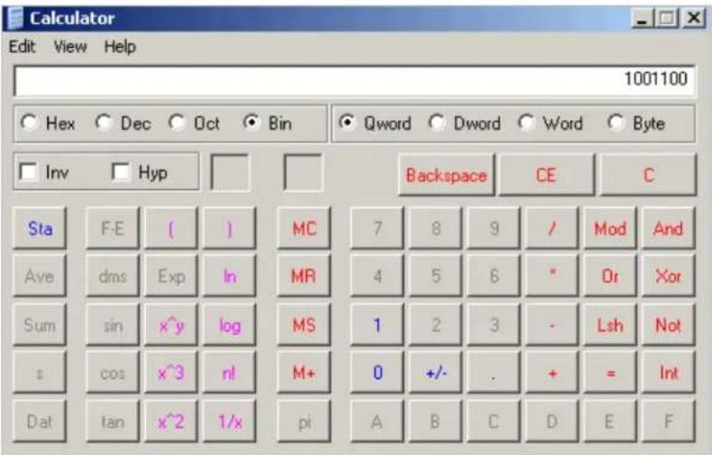
- Click Hex. The hexadecimal value appears.
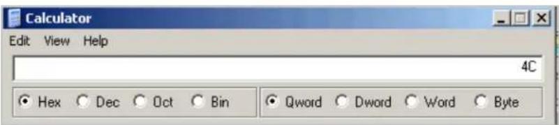
C: Lantronix Cables and Adapters
Lantronix cables and adapters for use with the EDS devices are listed here according to part number and application.
| LantronixP/N | Description Applications | |
| 500-103 6' RJ45-to DB9F Included with EDS8/16/32PR for setup or device connectivity. Connects the RJ45 RS232 serial ports of EDS8/16/32PR to a DB9M DTE interface of a PC or serial device. | ||
| 200.2062 Cable EthernetCAT5; RJ45, 2 m (6.6 ft) | Connects the EDS8/16/32PR Ethernet ports to an Ethernet switch/hub or is used for cascading from one EDS8/16/32PR to another. Connects the EDS8/16/32PR serial RJ45 RS232 ports to a device using one of the adapters listed below. | |
| 200.2063 Cable EthernetCAT5; RJ45, 5 m (16.4 ft) | Connects the EDS8/16/32PR Ethernet ports to an Ethernet switch/hub or is used for cascading from one EDS8/16/32PR to another. Connects the EDS8/16/32PR serial RJ45 RS232 ports to a device using one of the below listed adapters. | |
| 200.2064 Cable EthernetCAT5; RJ45, 10 m (32.8 ft) | Connects the EDS8/16/32PR Ethernet ports to an Ethernet switch/hub or is used for cascading from one EDS8/16/32PR to another. Connects the EDS8/16/32PR serial RJ45 RS232 ports to a device using one of the adapters listed below. | |
| 200.2065 Cable EthernetCAT5; RJ45, 15 m (49.2 ft) | Connects the EDS8/16/32PR Ethernet ports to an Ethernet switch/hub or is used for cascading from one EDS8/16/32PR to another. Connects the EDS8/16/32PR serial RJ45 RS232 ports to a device using one of the adapters listed below. | |
| 200.2066A Adapter RJ45-to-DB25M | Allows a standard straight-pinned CAT5 cable to connect the EDS8/16/32PR RJ45 serial ports to the DB25F DTE interface of | |
| a serial device. | ||
| 200.2067A Adapter RJ45-to-DB25F | Allows a standard straight-pinned CAT5 cable to connect the EDS8/16/32PR RJ45 serial ports to the DB25M DTE interface of a serial device. | |
| 200.2069A Adapter RJ45-to-DB9M | Allows a standard straight-pinned CAT5 cable to connect the EDS8/16/32PR RJ45 serial ports to the DB9F DCE interface of a serial device. | |
| 200.2070A Adapter RJ45-to-DB9F | Allows a standard straight-pinned CAT5 cable to connect the EDS8/16/32PR to the DB9M DTE interface of a PC or serial device. | |
| 200.2073 Adapter RJ45-to-DB25M | Allows a standard straight-pinned CAT5 cable to connect the EDS8/16/32PR RJ45 serial ports to the DB25F DCE interface of a serial device. | |
| 200.2074 Adapter RJ45-to-DB25F | Allows a standard straight-pinned CAT5 cable to connect the EDS8/16/32PR RJ45 serial ports to the DB25M DCE interface of a serial device. | |
| ADP010104-01 | Adapter "Rolled" RJ45-to-RJ45 | Allows a standard straight-pinned CAT5 cable to connect the EDS8/16/32 to an RJ45 console port on products from Cisco and other manufacturers. |
D: Compliance
The following compliances are according to ISO/IEC Guide 22 and EN 45014.
Manufacturer's Name & Address:
Lantronix 15353 Barranca Parkway, Irvine, CA 92618 USA
Declares that the following product:
Product Name and Model: EDS4100 4 Port Device Server, EDS16PR 16 Port
Device Server, and EDS32PR 32 Port Device Server, EDS8PS 8 Port Device Server, and EDS16PS 16 Port Device Server,
Conform To The Following Standards Or Other Normative Documents:
Radiated and conducted emissions
Class B limits of EN 55022:1998
EN55024: 1998 + A1: 2001
Direct & Indirect ESD
EN61000-4-2: 1995
RF Electromagnetic Field Immunity
EN61000-4-3: 1996
Electrical Fast Transient/Burst Immunity
EN61000-4-4: 1995
Surge Immunity
EN61000-4-5: 1995
RF Common Mode Conducted Susceptibility
EN61000-4-6: 1996
Power Frequency Magnetic Field Immunity
EN61000-4-8: 1993
Voltage Dips and Interrupts
EN61000-4-11: 1994
Manufacturer's Contact:
Director of Quality Assurance, Lantronix
15353 Barranca Parkway, Irvine, CA 92618 USA
Tel: 949-453-3990
Fax: 949-453-3995
RoHS Notice:
All Lantronix products in the following families are China RoHS-compliant and free of the following hazardous substances and elements:
| Lead (Pb) | Mercury (Hg) | Polybrominated biphenyls (PBB) |
| Cadmium (Cd) | Hexavalent Chromium (Cr (VI)) | Polybrominated diphenyl ethers (PBDE) |
| Product Family Name | Toxic or hazardous Substances and Elements | |||||
| Lead (Pb) | Mercury (Hg) | Cadmium (Cd) | Hexavalent Chromium (Cr (VI)) | Polybrominated biphenyls (PBB) | Polybrominated diphenyl ethers (PBDE) | |
| UDS1100 and 2100 0 0 0 0 0 | 0 | |||||
| EDS 0 0 0 0 0 0 | ||||||
| MSS100 | 0 0 0 | 0 0 0 | ||||
| IntelliBox | 0 0 0 | 0 0 0 | ||||
| XPress DR & XPress-DR+ 0 0 | 0 0 0 0 | |||||
| SecureBox 1101 & 2101 | 0 0 0 | 0 0 0 | ||||
| WiBox | 0 0 0 | 0 0 0 | ||||
| UBox | 0 0 0 | 0 0 0 | ||||
| MatchPort | 0 0 0 | 0 0 0 | ||||
| SLC | 0 0 0 | 0 0 0 | ||||
| XPort | 0 0 0 | 0 0 0 | ||||
| WiPort | 0 0 0 | 0 0 0 | ||||
| SLB | 0 0 0 | 0 0 0 | ||||
| SLP | 0 0 0 | 0 0 0 | ||||
| SCS 0 0 0 0 0 0 | ||||||
| SLS | 0 0 0 | 0 0 0 | ||||
| DSC | 0 0 0 | 0 0 0 | ||||
O: toxic or hazardous substance contained in all of the homogeneous materials for this part is below the limit requirement in SJ/T11363-2006.
X: toxic or hazardous substance contained in at least one of the homogeneous materials used for this part is above the limit requirement in SJ/T11363-2006.
Lithium Battery Notice
WARNING: DANGER OF EXPLOSION IF BATTERY IS INCORRECTLY REPLACED. REPLACE ONLY WITH THE SAME OR EQUIVALENT TYPE RECOMMENDED BY THE MANUFACTURER. DISCARD USED BATTERIES ACCORDING TO THE MANUFACTURER'S INSTRUCTIONS.
Installation Instructions
Rack Mounting
If rack mounted units are installed in a closed or multi-unit rack assembly, they may require further evaluation by certification agencies. You must consider the following items:
- The ambient conditions within the rack may be greater than the room conditions. Installation should be so that the amount of air flow required for safe operation is not compromised. The maximum temperature for the equipment in this environment is 50^ C. Consideration should be given to the maximum rated ambient conditions.
- Installation should be so that a hazardous stability condition is not achieved due to uneven loading.
Input Supply
Check nameplate ratings to assure there is no overloading of supply circuits that have an effect on over current protection and supply wiring.
Grounding
Reliable earthing of this equipment must be maintained. Particular attention should be given to supply connections when connecting to power strips, rather than direct connections to the branch circuit strips.
E: Warranty
For details on the Lantronix warranty replacement policy, go to our web site at http://www.lantronix.com/support/warranty/index.html
Index
A
Accessing MatchPort b/g Pro, 38
Address
Ethernet, 20
Hardware, 20
IP, 20
MAC, 20
ARP Settings, 108
B
Bar code, 21
Binary to hexadecimal conversions, 152
Branding, 12, 148
Command Mode, 149
Web Manager Customization, 148
C
CipherSuites, 144
Command Line Interface Settings, 124
Command-Line Interface, 17
Compliance, 156
Configuration methods, 19
Configuration Settings, 78
Create New Self-Signed Certificate, 100
D
default server port numbers, 20
Device Control, 18
Device Details Summary, 39
Device Management, 19
Device Status, 46
diagnostic toolset, 19
Diagnostics, 110
Buffer Pools, 115
DNS Lookup, 114
Hardware, 110
IP Sockets, 112
Memory, 115
MIB-II Statistics, 111
Ping, 112
Processes, 117
Traceroute, 113
Diagnostics Settings, 103
DNS Configuration, 78
DSA, 146
E
EDS16/32PR
Features, 16
Hardware components, 23, 34
Installation, 25, 36
Overview, 16, 33
Package contents, 22, 33
Reset button, 25, 36
Serial ports, 24, 34
User-supplied Items, 22, 33
EDS16/32PS
Features, 13
EDS4100
Ethernet port, 29
Features, 15
Hardware components, 28
Installation, 31
LEDs, 30
Overview, 14, 27
Package contents, 27
Reset button, 31
Serial ports, 28
Terminal block connector, 30
User-supplied Items, 27
Email, 121
encrypt, 18
Enterprise-Grade Security, 18
Ethernet address, 20
Ethernet port, 24, 35
Evolution OS ^TM , 17
F
Features
EDS4100, 15
File System
Browser, 104
Configuration, 103
Statistics, 103
Filesystem, 44
Firmware, 150
FreeRadius, 147
FTP Configuration, 80
H
Hardware Address, 20
Host Configuration, 75
HTTP
Authentication, 87
Change Configuration, 85
Configuration, 83
Statistics, 83
|
ICMP Settings, 107
Installation
Line Terminal Configuration, 72
locating a MatchPort b/g Pro unit, 11, 38
LPD
Configuration Page, 91
Settings, 90
Statistics Page, 90
M
MAC Address, 20
Maintenance Settings, 11, 103
Modem Emulation, 17
N
Network Settings
Network 1 Interface Configuration, 48
Network 1 Interface Status, 47
Network Terminal Configuration, 74
0
OpenSSL, 146
P
Part number, 21
Port Numbers, 20
Port Numbers, 20
Ports
Serial and Telnet, 19
Product ID, 21
Product Information Label, 21
protection levels, 18
Protocol Stack Configuration, 106
Protocols Supported, 17
Q
Query Port, 110
R
Reset button
EDS4100, 31
Reset button
EDS16/32PR, 25
Reset button
EDS16/32PR, 36
RSA, 146
RSS, 18
RSS Settings, 89
S
SCPR, 18
Secure Com Port Redirector, 18
Secure Shell, 142
Secure Sockets Layer, 144
Security
in Detail, 142
Security
Enterprise-Grade, 18
Services Settings, 78
SNMP Configuration, 78
SNMP Management, 18
SSH
Client Configuration, 144
Client Known Hosts, 96
Client User Configuration, 97
protection level, 18
Server Authorized Users, 95
Server Configuration, 142
Server Host Keys, 93
Settings, 93
SSL
Certificates, 145
protection level, 18
Settings, 99
Utilities, 146
SSL standard, The, 144
Steel Belted Radius, 147
Syslog Configuration, 82
T
TCP Settings, 106
Technical Support, 151
Telnet port, 19
Terminal
page, 72
Server, 19
TFTP Configuration, 81
Time settings, 119
Troubleshooting Capabilities, 19
Tunnel Settings
Accept Mode, 58
AES Keys, 71
Connect Mode, 64
Disconnect Mode, 70
Modem Emulation, 67
Packing Mode, 60
Serial Settings, 63
Start and Stop Characters, 69
Tunnel 1 – Statistics, 57
Tunneling
Accept Mode, 137
Connect Mode, 136
Disconnect Mode, 138
Modem Emulation, 139
Packing Mode, 138
Serial Line Settings, 140
Statistics, 141
U
Updating Firmware, 150
Upload Authority Certificate, 100
Upload Certificate, 100
W
Web Manager
accessing, 41
navigating, 44
page summary, 44
Web-Based Configuration, 17
WLAN
Settings
Network 1 Ethernet Link, 51
X
XML
Export Configuration, 126
Export Status, 129
Import System Configuration, 130
XML, 19
XML Configuration, 126
XML-Based Architecture, 18
- EDS Device Servers and Terminal Servers
- User Guide
- Contacts
- Lantronix Corporate Headquarters
- Technical Support
- Sales Offices
- Disclaimer
- Revision History
- Contents
- 1: Using This Guide 11
- 2: Introduction 13
- 3: Installation of EDS8PS and EDS16PS 22
- 4: Installation of EDS4100 27
- 5: Installation of EDS8PR, EDS16PR, or EDS32PR 33
- 6: Using DeviceInstaller 38
- 7: Configuration Using Web Manager 41
- 8: Network Settings 47
- 9: Line, Tunnel, Terminal, and Host Settings 52
- 10: Services Settings 78
- 11: Security Settings 93
- 12: Maintenance and Diagnostics Settings 103
- 13: Advanced Settings 121
- 14: Tunneling 136
- 15: Security in Detail 142
- 16: Branding the EDS 148
- 17: Updating Firmware 150
- A: Technical Support 151
- B: Binary to Hexadecimal Conversions 152
- C: Lantronix Cables and Adapters 154
- D: Compliance 156
- E: Warranty 160
- Index 161
- Figures
- 1: Using This Guide
- Purpose and Audience
- Summary of Chapters
- Additional Documentation
- 2: Introduction
- EDS8PS and EDS16PS Overview
- Features
- EDS4100 Overview
- Protocols Supported
- Evolution OS™
- Additional Features
- Modem Emulation
- Web-Based Configuration and Troubleshooting
- Command-Line Interface (CLI)
- SNMP Management
- XML-Based Architecture and Device Control
- Really Simple Syndication (RSS)
- Enterprise-Grade Security
- Terminal Server/Device Management
- Troubleshooting Capabilities
- Configuration Methods
- Addresses and Port Numbers
- Hardware Address
- Figure 2-4. Sample Hardware Address
- IP Address
- Port Numbers
- Product Information Label
- 3: Installation of EDS8PS and EDS16PS
- Package Contents
- User-Supplied Items
- Identifying Hardware Components
- Serial Ports
- Console Port
- Ethernet Port
- LEDs
- LED Description
- Reset Button
- Reboot the device:
- Restore factory defaults:
- Installing the EDS8/16PS
- Finding a Suitable Location
- Connecting the EDS8/16PS
- Connect the EDS8/16PS to one or more serial devices.
- 4: Installation of EDS4100
- Terminal Block Connector
- Physically Installing the EDS4100
- Connecting the EDS4100
- Connect the EDS4100 to one or more serial devices.
- 5: Installation of EDS8PR, EDS16PR, or EDS32PR
- Product Label
- Installing the EDS8/16/32PR
- Connecting the EDS8/16/32PR
- 6: Using DeviceInstaller
- Accessing an EDS using Devicelnstaller
- Device Details Summary
- 7: Configuration Using Web Manager
- Accessing Web Manager through a Web Browser
- Web Manager Page Components
- Navigating the Web Manager
- Device Status Page
- 8: Network Settings
- Network Settings
- Network 1 (eth0) Interface Status
- View the network interface status:
- Network 1 (eth0) Interface Configuration
- View and configure network interface settings:
- Click Network 1, Interface, and Configuration.
- Enter or modify the following settings:
- Network 1 Ethernet Link
- View and configure the Ethernet link:
- 9: Line, Tunnel, Terminal, and Host Settings
- Line Settings
- Line Statistics
- Line Configuration
- Configure Line n:
- Line Command Mode
- Configure Line n Command Mode:
- Tunnel Settings
- View Tunnel – Statistics
- Accept Mode
- Configure Accept Mode:
- Click Submit.
- Packing Mode
- Configure the Tunnel Packing Mode:
- Serial Settings
- Configure serial settings:
- Connect Mode
- Configure Connect Mode:
- Configure modem emulation:
- Start and Stop Characters
- Configure the start and stop characters mode:
- Disconnect Mode
- Configure the tunnel Disconnect Mode:
- AES Keys
- Configure the AES keys for connect or Accept Mode:
- Tunnel 1 - AES Keys
- Terminal Settings
- Line Terminal Configuration
- Network Terminal Configuration
- Host Configuration
- Login Connect Menu
- Preview the Login Connect Menu
- 10: Services Settings
- DNS Configuration
- SNMP Configuration
- Configure SNMP:
- FTP Configuration
- Configure FTP:
- TFTP Configuration
- Configure TFTP:
- Syslog Configuration
- HTTP Configuration
- HTTP Statistics
- View HTTP statistics:
- Change HTTP Configuration
- Configure HTTP:
- HTTP Authentication
- Configure HTTP authentication settings:
- RSS Settings
- Configure RSS settings:
- LPD Settings
- LPD Statistics Page
- View LPD statistics:
- LPD Configuration Page
- Configure LPD settings:
- 11: Security Settings
- SSH Settings
- SSH Server Host Keys
- Configure the SSH server host keys:
- SSH Server Authorized Users
- Configure the SSH server for authorized users:
- SSH Client Known Hosts
- Configure the SSH client for known hosts:
- SSH Client User Configuration
- Configure the SSH client users:
- SSL Settings
- Configure the EDS SSL settings:
- 12: Maintenance and Diagnostics Settings
- File System Configuration
- File System Statistics
- To view file system statistics, compact, or format the EDS file system:
- File System Browser
- Browse the EDS file system:
- Protocol Stack Configuration
- Configure the EDS network stack protocols:
- TCP Settings
- IP Setting
- ICMP Settings
- ARP Settings
- IP Address Filter
- Configure the IP address filter:
- Query Port
- Configure the query port server:
- Diagnostics
- Hardware
- Display the EDS hardware diagnostics:
- MIB-II Statistics
- View EDS MIB-II statistics:
- IP Sockets
- Display open network sockets on the EDS:
- Ping
- Ping a remote device or computer:
- Traceroute
- Use Traceroute from the EDS:
- DNS Lookup
- Use forward or reverse DNS lookup:
- Memory
- Display memory statistics for the EDS:
- Buffer Pools
- Display the EDS buffer pools:
- Processes
- Display the processes running on the EDS:
- Real Time Clock Page
- Real Time Clock Page settings
- System Configuration
- Configure the EDS system settings:
- 13: Advanced Settings
- Email Configuration
- Email Statistics
- View email statistics.
- Configure EDS email settings:
- Command Line Interface Settings
- Command Line Interface Statistics
- View command line interface statistics:
- CLI Configuration
- Configure the CLI:
- XML Configuration
- XML: Export Configuration
- Export a system configuration record:
- Click Export.
- XML: Export Status
- Click the Export button.
- XML: Import System Configuration Page
- Import a system configuration:
- Import Configuration from External File
- Import Configuration from the Filesystem
- Import Line(s) from Single Line Settings on the File system
- XML: Import Lines from Single Line(s) Settings
- 14: Tunneling
- Connect Mode supports the following protocols:
- Connect Mode has six states:
- Accept Mode supports the following protocols:
- Accept Mode has the following states:
- The following settings end a connection:
- The following settings are configurable for Packing Mode:
- Command Mode
- Serial Line Settings
- Statistics
- 15: Security in Detail
- Secure Shell: SSH
- SSH Server Configuration
- Use the EDS to Generate the Keys:
- Click Submit.
- Generate and use keys from PuTTY:
- Use RFC4716-format Keys
- Specify Authorized Users.
- SSH Client Configuration
- Configure SSH client settings:
- Secure Sockets Layer (SSL)
- Cipher Suites
- Certificates
- Security Certificate Principles
- RSA or DSA
- Obtaining a Certificate and Private Key
- Utilities
- OpenSSL
- Generate a self-signed RSA certificate/key combo:
- Steel Belted Radius
- FreeRadius
- 16: Branding the EDS
- Web Manager Customization
- Change the EDS short and long names with the Web Manager:
- 17: Updating Firmware
- Obtaining Firmware
- Loading New Firmware
- Upload new firmware:
- A: Technical Support
- Technical Support US
- Technical Support Europe, Middle East, Africa
- B: Binary to Hexadecimal Conversions
- Converting Binary to Hexadecimal
- Conversion Table
- Scientific Calculator
- C: Lantronix Cables and Adapters
- D: Compliance
- Power Frequency Magnetic Field Immunity
- Voltage Dips and Interrupts
- Manufacturer's Contact:
- Lithium Battery Notice
- Installation Instructions
- Rack Mounting
- Input Supply
- Grounding
- E: Warranty
- Index
- A
- B
- C
- D
- E
- F
- H
Brand : Lantronix
Model : EDS8PS
Category : Server