
V-D11025A - Wristwatch Valcom - Free user manual and instructions
Find the device manual for free V-D11025A Valcom in PDF.


| Product Type | Analog Quartz Wristwatch |
| Case Material | Stainless Steel |
| Case Diameter | 40 mm |
| Case Thickness | 10 mm |
| Band Material | Leather |
| Band Width | 20 mm |
| Weight | 80 g |
| Power Source | Battery (SR626SW or equivalent) |
| Display Type | Analog with hour, minute, second hands |
| Water Resistance | 3 ATM (30 meters) |
| Crystal Material | Mineral Glass |
| Clasp Type | Buckle |
| Functions | Time display, date window at 3 o'clock |
| Care Instructions | Wipe with soft cloth; avoid contact with solvents; remove before showering or swimming |
| Safety Warnings | Keep away from strong magnetic fields; do not expose to extreme temperatures |
| Spare Parts Availability | Batteries and straps available from authorized dealers |
| Repairability | Battery replacement by professional recommended |
| General Information | Manufactured by Valcom; model V-D11025A |
Frequently Asked Questions - V-D11025A Valcom
User questions about V-D11025A Valcom
0 question about this device. Answer the ones you know or ask your own.
Ask a new question about this device
Download the instructions for your Wristwatch in PDF format for free! Find your manual V-D11025A - Valcom and take your electronic device back in hand. On this page are published all the documents necessary for the use of your device. V-D11025A by Valcom.
USER MANUAL V-D11025A Valcom
Installation Manual V1.03
V-D2425 and V-D2440 Digital Clock

V-D2425 and V-D2440 Wired Clock
Table of Contents
Table of Contents—2
Flush Mount Installation—3
Surface (Wall) Mount Installation—4
Metal Double Mount Installation—5
Plastic Surface (Wall) Mount Installation—6
Plastic Surface (Wall) Mount Installation—7
Plastic Double Mount Installation—8
Plastic Double Mount Installation—9
Plastic Double Mount Installation—10
Wiring and Jumper Settings—11
2 Wire Digital Communication Wiring Information—12
Troubleshooting—13
Frequently Asked Questions—14
Compliances—15
Installation Instructions
Flush Mount Installation

- Mount the flush mount box into the wall.
- Connect the ground wire into the flush mount box using the tooth lockwasher and the machine screw nut (included in the kit).
- Disconnect the red filter from the display panel.
- Connect the wiring as shown on the wiring diagram.
- IMPORTANT: If using a low voltage system (24 volt) make sure that the transformer is an isolated transformer.
- Mount the display panel into the flush mount box using the four (4) black machine screws (#6, included in the kit). Make sure the switches are on the right side.
- Snap the red filter into the display panel.
Installation Instructions
Flush Mount Installation
Figure 1

Flush Mount Picture 4.0"
Figure 2
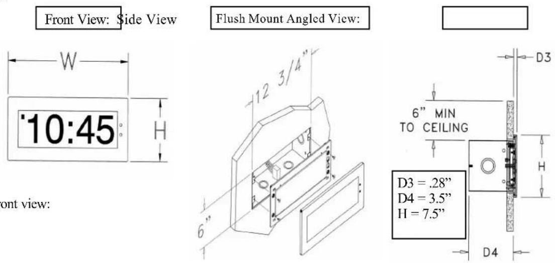
Front view:
Installation Instructions
Surface (Wall) Mount Installation

- Mount the wall mount box into the double gang box using four machine screws (#6-32) included in the kit.
- Connect the ground wire into the flush mount box using the tooth lockwasher and machine screw nut (included in the kit).
- Disconnect the red filter from the display panel.
- Connect the wiring as shown on the wiring diagram.
- IMPORTANT: If using a low voltage system (24 volt) make sure that the transformer is an isolated transformer.
- Mount the display panel into the flush mount box using four (4) black machine screws (#6, included in the kit). Make sure the switches are on the right side.
- Snap the red filter into the display panel.
Installation Instructions
Metal Double Mount Installation

- Screw hanger/mounting rod (included in the kit) into the crossbar (also included in the kit).
- Insert wires through hanger/mounting rod.
- Install crossbar using two (2) #6-32 screws into double gang box.
- Mount the double mount box into the clock base using two (2) #6 nuts and Tooth Lockwasher #6. (The double mount can be mounted either on the wall or on the ceiling).
- Insert the two (2) locking hole plugs (0.187") and the locking hole plug (0.562") into the unused holes.
- Insert double mount case onto the hanger/mounting rod.
- Insert the support bracket onto the hanger/mounting rod.
- Screw the two (2) nuts (included in the kit) onto hanger/mounting rod and secure the clock base to wall.
- Connect the ground wire into the double mount box using the tooth lockwasher and machine screw nut (included in the kit).
- Disconnect the red filter from the display panel.
- Connect the wiring as shown on the wiring diagram.
- IMPORTANT: If using a low voltage system (24 volt) make sure that the transformer is an isolated transformer.
- Mount the display panel on one side of the double mount box using four (4) black machine screws (#6, included in the kit). Make sure the switches are on the right side.
- Snap the red filter into the display panel.
- Repeat steps 9-13 for the second clock.
Installation Instructions
Plastic Surface (Wall) Mount Installation
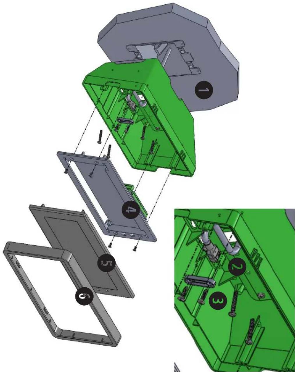
Plastic Surface (Wall) Mount Installation
Mount Housing to Wall and/or Gang Box - To mount the housing to the wall, drive two (2) plastic anchors into the wall (not supplied in kit) and take two pan head screws (also not supplied in kit) and drive them into the plastic inserts leaving an 1/8th inch gap between the head of the screw and the wall. Mount the housing to the wall by lining up the two holes in the back of the top of the housing with the two screws with the 1/8 inch gap from the wall and slide the housing onto the heads of the screws. To mount the housing to the gang box, take the four (4) 6-32 x 1" screws (supplied in kit) and screw them through the four holes in the center of the inside of the housing and the four holes in the gang box.
Note: If using a metal gang box, a ground must be provided to the gang box.
2 Feed Wiring Into the Housing - Take the wire coming from the inside of the gang box and feed it through the hole in the middle of the housing.
3 Plug and Secure Wiring - Loosen the provided wire clamp (comes attached to the inside of the housing) and slip excess wiring through and tighten the clamp. After securing excess wiring, plug the jack at the end of the wiring into the appropriate jack on the back of the display board.
4 Mount Display Board to Housing - Using the four (4) self tapping, 6-19 x 1/2" flat head screws supplied in the assembly kit, take the display board and screw it to the front side of the clock housing (4 screws per clock).
5 Snap on Filter - Take the red filter bezel and snap it on to the front side of the housing.
6 Snap on Frame - Take the gray frame and snap it on to the front side of the housing.
Installation Instructions
Plastic Double Mount Installation

*For metal mounting bracket: Use a wall anchor that can support 50 lbs or more with a maximum screw size of 10/1.5"
1 Install metal mounting bracket - First, remove the metal mounting bracket from the inside of the double mount base by unscrewing the two (2) 6-32 x 1/2" screws located on the underside of the base (save these screws for step #5). Next, screw the metal mounting bracket to the wall or ceiling in which the clocks are being installed. To mount to the switch box, screw the four (4) 6-32 x 1" screws supplied in the assembly kit through the inner four holes of the metal mounting bracket. Use the outer four holes to mount anchors to the wall (both anchors and screws for anchors not supplied in kit). For IP clocks, if using an Ethernet bracket (*as shown in the diagram) use the two (2) 6-32 x 1/4" included in the assembly kit to mount the Ethernet bracket to the metal mounting bracket at this point(Ethernet bracket not supplied in assembly kit).
Note: if using a plastic switch box, a ground wire must be routed through the switch box and into one (1) of the four (4) metal mounting bracket screws in order to provide ground to the metal mounting bracket.
Note: the metal mounting bracket MUST be secured by both the screws going to the switch box AND the anchors going into the wall.
2 Mount clock housings to pole - Align the hole in the center each housing with one of the three holes on the mounting pole where the wiring will be routed (the installer will chose which hole at the end of the pole to use based on how far they want the clock to sit from the wall). Screw from the inside of the housing into the four holes surrounding the hole in the center of the housing using the four (4) 8-32 x 7/16" screws supplied in the assembly kit (4 screws per clock), securing both housings to the mounting pole.
Note: end caps from one side of each clock must be removed to mount both clocks to the mounting pole. Remove one end cap from each clock from the side in which the mounting pole enters the clock.
3 Screw both housings together - Using the two (2) self tapping, 6-19 x 7/16" screws supplied in the assembly kit, screw both back sides of the clock housings together (2 screws per clock).
4 Feed wiring through base and pole - Take the wiring coming from the switch box and begin to feed it through the center of the base of the mounting assembly until it emerges from the hole in the center of the clock housing. Make sure there is roughly 1.5' - 2' of wiring coming from the switch box. Perform this task for both clocks. If installing IP clocks, run bare Ethernet wire without an RJ45 connector and install the connector after it has been routed through the clock if possible (this will be much easier than running the wire with the connector on). If not possible, make sure that there is no boot present in order for the connector to fit through the assembly. If you are using an Ethernet bracket with the installation of IP clocks, the assembly of the clocks in steps 6 and 7 can be accomplished before mounting the assembly to the wall in step 5 - making the overall installation more simple.
Installation Instructions
Plastic Double Mount Installation
5 Snap and screw base to metal mounting bracket - Snap the base to the metal mounting bracket by first making contact with the lip in the upper side of the base and the metal mounting bracket. When the base has been snapped onto the bracket, take the two (2) 6-32 x 1/2" pan head screws that originally came installed on the base and screw them back into the two holes on the underside of the base to secure the base to the metal mounting bracket.
6 Connect switch box wires to clock harness - Take the wiring harness supplied with the clock and make all necessary connections between the wiring harness and the switch box wires using wire nuts. Perform this task for both clocks. If using IP clocks, wiring will not be supplied with the clocks - the installer will be responsible for supplying all Ethernet wiring.
7 Plug and secure wiring - Loosen and slip excess wiring through provided wire clamp (comes attached to each housing) and tighten the clamp. After securing excess wiring, plug the jack at the end of the wiring harness into the appropriate jack on the back of the display board. Perform this task for both clocks.
8 Mount display board to housing - Using the four (4) self tapping, 6-19 x 1/2" flat head screws supplied in the assembly kit, take the display board and screw it to the front side of the clock housing (4 screws per clock).
9 Snap on filter - Take the red filter bezel and snap it on to the front side of each clock housing.
10 Snap on frame - Take the gray frame and snap it on to the front side of each clock housing.
Wiring Information
Wiring and Jumper Settings
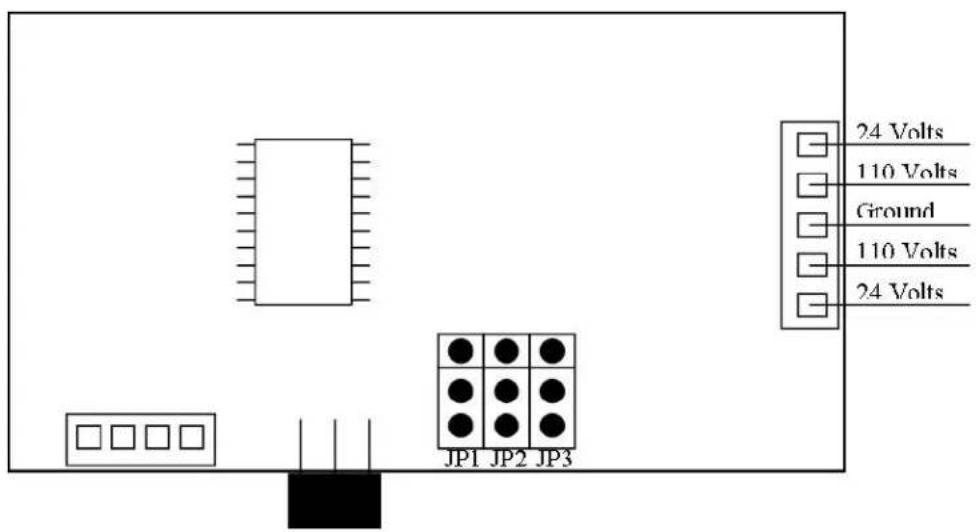
Jumper Number On Off
JP1 - 12/24 Hour Mode 12 Hour Mode 24 Hour Mode
JP2 - Brightness Brightest Bright
JP3 - Loss of Communication Alert 5 Minutes 1 Hour
Wiring Information
2 Wire Digital Communication Wiring Information
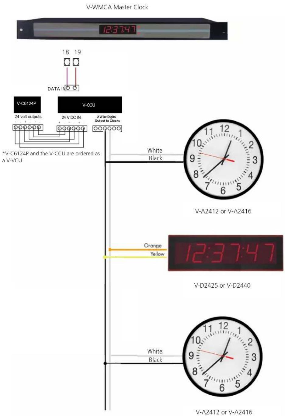
Support
Troubleshooting
The clock is not running. What do I do?
a) Measure the input voltage to the clock. The voltage should measure 85-135 volts in the 110 volt model or 10-28 volts in the 2.5"/24 volt model and 16-28 volt in the 4.0"/24 volt model.
b) Make sure the transformer is an isolated transformer if using a 24 volt model.
c) Make sure the ground wire is not touching other wires.
NOTE: If you fail to follow instructions a and b listed above, the fuses can be blown.
Clock is only displaying dashes. What do I do?
This means that the clock is receiving power but not receiving a time correction signal.
a) Confirm that the head end is sending data to the clock power supply
b) Confirm that clock power supply is wired correctly
The clock is displaying a time, but the colons are flashing. What does this mean?
This means that the clock, at one point has received a time update, but since then the correction has been lost.
a) Confirm that the head end is sending data to the clock power supply
b) Check to see that all wiring is correctly.
Support
Frequently Asked Questions
Can the digital clock be used as an independent clock?
No, the V-D2425 and V-D2440 digital clock requires a communication input and must be used with either a master clock or a V-D11025A or V-D11040A digital clock.
Some clocks require a 9 volt battery backup for timekeeping. What happens to the V-D2524 or V-D2540 if a power failure occurs?
Upon restoration of power, the clock immediately receives a correction signal from the master clock and resets itself to display the correct time. This occurs within seconds of "power-up", so no battery backup is required for a timekeeping base within the individual clocks. Since the clock does not require a battery backup, the clock never needs to be opened.
How can I interface the V-D2524 or V-D2540 with Rauland, Dukane and other systems?
The V-WMCA Master Clock or the V-D11025A or V-D11040A digital clock can be used as an interface between other systems and V-D2524 or V-D2540 clocks.
What happens if voltage on the power line drops from 24 VAC to lower voltage?
The clock will still function, and will maintain the same level of brightness. However, the current consumption will increase proportionally to the decrease in voltage.
Compliances

FCC Part 15b Industry Canada
FCC Statement: Information to the user (for U.S. only)
This equipment has been tested and found to comply with the limits for a Class B digital device, pursuant to part 15 of the FCC Rules. These limits are designed to provide reasonable protection against harmful interference in a residential installation. This equipment generates, uses and can radiate radio frequency energy and, if not installed and used in accordance with the instructions, may cause harmful interference to radio communications. However, there is no guarantee that interference will not occur in a particular installation. If this equipment does cause harmful interference to radio or television reception, which can be determined by turning the equipment off and on, the user is encouraged to try to correct the interference by one or more of the following measures:
- Reorient or relocate the receiving antenna.
- Increase the separation between the equipment and receiver.
- Connect the equipment into an outlet on a circuit different from that to which the receiver is connected.
- Consult the dealer or an experienced radio/TV technician for help.
The user is cautioned that any changes or modifications not expressly approved by the party responsible for compliance could void the user's authority to operate the equipment.
This unit was tested with shielded cables on the peripheral devices. Shielded cables must be used with the unit to ensure compliance.
IC Statement (for Canada only)
This Class B digital apparatus complies with Canadian ICES-003.
CE Declaration of Conformity
We, The Sapling Company certify and declare under our sole responsibility that the SBD 1000, V-D2425 and V-D2440 conform with the essential requirements of the EMC Directive 2004/108.EC and LVD 2006/95/EC, based on the following standards applied:
EN 55022: 2006
EN 61000-3-2: 2006
EN 61000-3-3: 1995 /A1: 2001 /A2:2005
EN 55024 : 1998 /A1:2001, A2:2003
EN 60950-1:2006 - Safety Part 1
- V-D2425 AND V-D2440 DIGITAL CLOCK
- V-D2425 AND V-D2440 WIRED CLOCK
- TABLE OF CONTENTS
- INSTALLATION INSTRUCTIONS
- FLUSH MOUNT INSTALLATION
- SURFACE (WALL) MOUNT INSTALLATION
- METAL DOUBLE MOUNT INSTALLATION
- PLASTIC SURFACE (WALL) MOUNT INSTALLATION
- PLASTIC DOUBLE MOUNT INSTALLATION
- FOR METAL MOUNTING BRACKET: USE A WALL ANCHOR THAT CAN SUPPORT 50 LBS OR MORE WITH A MAXIMUM SCREW SIZE OF 10/1.5
- WIRING INFORMATION
- WIRING AND JUMPER SETTINGS
- SUPPORT
- TROUBLESHOOTING
- THE CLOCK IS NOT RUNNING. WHAT DO I DO
- CLOCK IS ONLY DISPLAYING DASHES. WHAT DO I DO
- FREQUENTLY ASKED QUESTIONS
- CAN THE DIGITAL CLOCK BE USED AS AN INDEPENDENT CLOCK
- SOME CLOCKS REQUIRE A 9 VOLT BATTERY BACKUP FOR TIMEKEEPING. WHAT HAPPENS TO THE V-D2524 OR V-D2540 IF A POWER FAILURE OCCURS
- HOW CAN I INTERFACE THE V-D2524 OR V-D2540 WITH RAULAND, DUKANE AND OTHER SYSTEMS
- WHAT HAPPENS IF VOLTAGE ON THE POWER LINE DROPS FROM 24 VAC TO LOWER VOLTAGE
- COMPLIANCES
- FCC PART 15B INDUSTRY CANADA
- IC STATEMENT (FOR CANADA ONLY)
- CE DECLARATION OF CONFORMITY
Brand : Valcom
Model : V-D11025A
Category : Wristwatch