M10e - Label printer SATO - Free user manual and instructions
Find the device manual for free M10e SATO in PDF.


| Product Type | Industrial Thermal Label Printer |
| Brand | SATO |
| Model | M10e |
| Print Method | Direct Thermal / Thermal Transfer |
| Print Width | 4.1 inches (104 mm) |
| Print Speed | Up to 8 ips (203 mm/s) |
| Resolution | 203 dpi (8 dots/mm) |
| Dimensions (W x D x H) | 10.4 in x 11.0 in x 7.5 in (265 x 280 x 190 mm) |
| Weight | 11.5 lbs (5.2 kg) |
| Power Supply | 100-240 VAC, 50/60 Hz, Auto-switching |
| Interfaces | USB 2.0, RS-232C Serial, Ethernet (10/100BaseT) |
| Memory | 16 MB Flash, 8 MB SDRAM, expandable via SD card |
| Media Types | Labels, Tags, Receipts, Continuous stock |
| Max Media Width | 4.5 inches (114 mm) |
| Max Media Roll Diameter | 8 inches (203 mm) O.D. |
| Barcode Symbologies | Code 39, Code 128, EAN-13, UPC-A, QR Code, DataMatrix, PDF417, etc. |
| Supported Languages | English, French, German, Spanish, Italian, etc. (via command codes) |
| Operating Temperature | 41°F to 104°F (5°C to 40°C) |
| Operating Humidity | 20% to 80% RH (non-condensing) |
| Maintenance | Clean print head with isopropyl alcohol after every ribbon roll; periodic cleaning of platen roller |
| Safety | Overcurrent protection, thermal shutdown, auto-cutter safety interlock |
| Spare Parts & Repairability | Print head, platen roller, cutter blade, power supply available as service parts |
Frequently Asked Questions - M10e SATO
User questions about M10e SATO
0 question about this device. Answer the ones you know or ask your own.
Ask a new question about this device
Download the instructions for your Label printer in PDF format for free! Find your manual M10e - SATO and take your electronic device back in hand. On this page are published all the documents necessary for the use of your device. M10e by SATO.
USER MANUAL M10e SATO
natural_image
Exterior view of a white industrial machine (no visible text or symbols)OPERATOR MANUAL
SATO America, Inc.
10350A Nations Ford Road
Charlotte, NC 28273
Main Phone: (704)644-1650
Tech Support Hotline: (704)644-1660
Fax: (707)644-1661
E-Mail: satosales@satoamerica.com
www.satoamerica.com
© Copyright 2003
SATO America, Inc.
All rights reserved. No part of this document may be reproduced or issued to third parties in any form whatsoever without the express permission of SATO America, Inc. The materials in this document is provided for general information and is subject to change without notice. SATO America, Inc. assumes no responsibilities for any errors that may appear.
Preliminary 11/12/02
TABLE OF CONTENTS
Section 1. Printer Overview
Introduction....1-1
Specifications....1-2
Section 2. Installation
Introduction....2-1
Installation 2-1
Dimensions 2-2
Components 2-3
Media Loading....2-5
Label Sensing....2-7
Operation Panel....2-8
Dip Switch Panel 2-9
Section 3. CONFIGURATION
Printer Dip Switch Configuration....3-1
Default Settings....3-7
Switch Selections....3-7
Potentiometer Adjustments....3-8
Pitch 3-8
LCD Panel Printer Configuration 3-10
Section 4. CLEANING AND MAINTENANCE
Introduction....4-1
Adjusting the Print Quality....4-1
Cleaning the Print Head, Platen and Rollers....4-2
Cleaning the Label Edge and Paper End Sensors ....4-4
Cleaning the Auto Load Sensor 4-5
Replacing the Print Head 4-6
Section 5. Troubleshooting
Initial Checklist....5-1
Using the IEEE1284 Parallel Interface....5-1
Using the RS232C Serial Interface....5-2
Using The Universal Serial Bus (USB) Interface....5-3
Using the Lan Ethernet Interface 5-3
Error Signals 5-6
Section 6. Interface Specifications
Introduction....6-1
Interface Types 6-1
The Receive Buffer....6-2
IEEE1284 Parallel Interface 6-3
RS232 Serial Interface 6-5
Universal Serial Bus (USB) Interface....6-7
Local Area Network (LAN) Optional Interface....6-8
BiDirectonal Communications 6-8
Section 7. Label Sheet Commands
Label Size 7-2
Label Start....7-3
Label Format....7-4
SLabel Variable Data....7-5
Label Print Quantity....7-6
Section 8. Optional Accessories
PCMCIA Memory Cards 8-1
Plug-in Interface Modules 8-2
Cutter 8-3
SECTION 1. PRINTER OVERVIEW
INTRODUCTION
The SATO M10e printer is a wide carriage thermal printer designed specifically to address need for large high resolution labels. It can print labels as large as 10.5" x 16.5" with a resolution of 305 dpi (dots per inch) at speeds up to 5 inches per second, making it ideal for large compliance label applications. All printer parameters are user programmable using the front panel controls and DIP switches. All popular bar codes and 14 human readable fonts, including vector and two raster fonts, are resident in memory providing literally thousands of type styles and sizes.
The M10e is available in two versions. The M10eDT is a direct thermal only version and must use thermally sensitive paper to print. The M10eTT is a thermal transfer model and has provisions for using a thermal transfer ribbon. It can also print in a direct thermal mode if the ribbon is not used.
This manual will help you understand the basic operations of the printer such as setup, installation, configuration, cleaning and maintenance.
The M10e uses the standard SATO Printing Language command codes. The only differences between it and other SATO printers are the allowable values representing the print positions on the label. These values are specified in “dots” and vary depending upon the resolution of the printer and the amount of memory available for imaging the label. The allowable ranges for the M10e are specified in the SATO “e” Printer Programming Reference. This commonality makes it easy to convert labels from one SATO printer without having to create an entirely different command stream. There are some caveats that must be observed though to compensate for the different resolution print heads. The effects of the different print resolutions are best illustrated by taking a label designed for a 305 dpi printer and sending the command stream to a 609 dpi printer. The label printed will be an exact one half scale, including the fonts, bar code dimensions and line length/widths. The only exceptions are the Postnet bar code and OCR-A and OCR-B fonts that have only one legal size and the printer resolution is automatically compensated for by the various printers. Conversely, a label designed for a 609 dpi printer and sent to its 305 dpi cousin will be twice as large. It probably will be “truncated” if the resulting size is larger than the maximum allowable for the printer.
GENERAL PRINTER SPECIFICATIONS
| SPECIFICATION M10e | |
| Method Direct or Thermal Transfer | |
| Speed (User Selectable) 2 to 10 ips | 50 to 125 mm/s |
| Print Module (Dot Size) ..0033 in. | .083 mm |
| Resolution 309 dpi | 12 d/mm |
| Maximum Print Width 10.5 in. | 266 mm |
| Maximum Print Length 16.5 in. | 420 mm |
| MEDIA | |
| Minimum Width 5.16 in. | 131 mm |
| Minimum Length 1.7 in. | 43 mm |
| Maximum Width 11.8 in. | 300 mm |
| Type Roll or Fan-Fold Die Cut Labels | Thermally Sensitive for M10eDT |
| Maximum Caliper 0.008 in. | 0.21 mm |
| Roll OD (max) Face-In | 7.8 in.200 mm |
| Core ID (min) | 3 in76.2 mm |
| SENSING | |
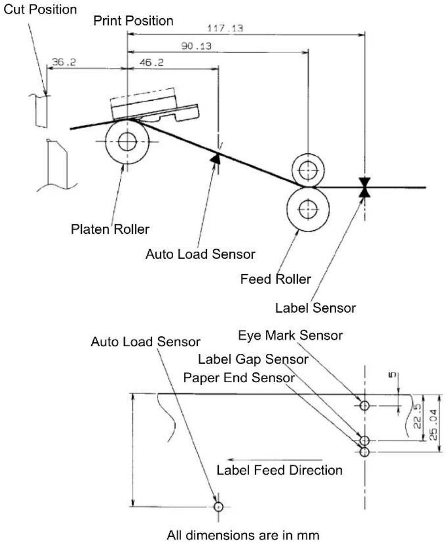
| See-Thru | Fixed, 0.9 in. (22.5 mm) left of center |
| Reflective Eye-Mark | Fixed, 0.2 in. (5 mm) from left label edge |
| Continuous Form | Not Used |
| RIBBON | |
| Widths | 6.5 in. (165 mm), 8.7 in. (220 mm), 10.7 in.(273 mm) |
| Length (max) | 984 ft. (300 m) |
| Thickness | 4.5 micron, Wound Face-In |
| CONTROLS AND INDICATORS | |
| Power Green LED | |
| On-Line Green LED | |
| Error Red LED | |
| LCD Panel 2 Line x 16 Character | |
| Auto-Load (Rear Panel) Green LED | |
| Power On/Off Switch Front | Casework |
| On/Off-Line Key Front Panel | |
| Feed Switch Key Front Panel | |
| Cursor Control Keys Front | Panel |
| Enter Key Front Panel | |
| POTENTIOMETER ADJUSTMENTS | |
| Print Darkness Top Panel | |
| Offset | Top Panel |
| Pitch | Top Panel |
| Display | Top Panel |
| INTERFACE CONNECTIONS(1) | |
| Parallel | IEEE1284 Standard |
| Serial | RS232C (9600 to 57600 bps) StandardRS422/485 (9600 to 57600 bps) OptionalReady/Busy or X-On/X-Off Flow ControlBi-directional Status |
| Universal Serial Bus | USB Ver. 1.1 Standard |
| Ethernet | 10/100BaseT |
| PROCESSING | |
| CPU | 32 Bit RISC |
| Flash ROM | 4 MB |
| SDRAM | 16 MB |
| Receive Buffer | 2.95 MB |
| Memory Expansion | See Options and Accessories |
| (1) Only one interface module can be installed in a printer at a time. | |
| MATRIX FONTS | |
| U Font 5 dots W x 9 dots H | |
| S Font 8 dots W x 15 dots H | |
| M Font 13 dots W x 20 dots H | |
| XU Font 5 dots H x 9 dots H (Helvetica) | |
| XS Font 17 dots H x 17 dots W (Univers Condensed Bold) | |
| XM Font 24 dots H x 24 dots W (Univers Condensed Bold) | |
| OA Font 22 dots W x 33 dots H (OCR-A) | |
| OB Font 30 Dots W x 36 dots H (OCR-B) | |
| AUTO SMOOTHING FONTS | |
| WB 18 dots W x 30 dots H | |
| WL 28 dots H x 52 dots H | |
| XB | 48 dots H x 48 dots W (Univers Condensed Bold) |
| XL 48 dots W x 48 dots H (Sans Serif) | |
| VECTOR FONT | |
| Proportional or Fixed SpacingFont Size 50 x 50 dots to 999 x 999 dotsHelvetica, 10 Font Variations | |
| AGFA® RASTER FONTS | |
| Font A | CG Times ®, 8 pt to 72 pt |
| Font B | CG Trimvirate®, 8 pt to 72 pt |
| DOWNLOADABLE FONTS | |
| Bit Mapped TrueType® Fonts with Utility Program | |
| CHARACTER CONTROL | |
| Expansion to 12X in either X or Y coordinatesCharacter Pitch controlLine Space controlJournal Print facility0°, 90°, 180° and 270° Rotation | |
| BAR CODE M10e | |
| SYMBOLOGIES | |
| Linear Bar Codes Bookland (UPC/EAN Supplemental) | |
| EAN-8/EAN-13 | |
| CODABAR | |
| CODE 39 | |
| CODE 93 | |
| CODE 128 | |
| Interleaved 2 of 5 (I 2/5) | |
| Industrial 2 of 5 | |
| Matrix 2 of 5 | |
| MSI | |
| POSTNET | |
| UCC/EAN-128 | |
| UPC-A/UPC-E | |
| Two Dimensional Data Matrix | |
| Maxicode | |
| PDF417 | |
| Micro PDF | |
| Truncated PDF | |
| QR Code | |
| 1:2, 1:3, 2:5, User Programmable | |
| Bar Height 4 to 999 dots, User | Programmable |
| Rotation 0°, 90°, 180° and 270° | Rotation |
| OTHER FEATURES | |
| Sequential Numbering Sequential | numbering of both numerics and bar codes |
| Custom Characters RAM storage for custom designed characters | |
| Graphics Dot addressable, SATO Hex/Binary, BMP or PCX formats | |
| Forms Overlay Overlay of predesigned forms in image buffer | |
| SPECIFICATION M10e | |
| PHYSICAL | |
| Wide 18.7 in. (475 mm) | |
| Deep 12.3 in. (313.4 mm) | |
| High 12.6 in.(319.2 mm) | |
| Weight 50.7 lb. (23 kg) | |
| POWER | |
| Input Voltage Autoswiching 100-240 VAC +/-10%, 60 Hz | |
| Power Consumption 560W Operating, 40W Idle | |
| ENVIRONMENTAL | |
| Operating Temperature 41° to 104°F (5° to 40°C) | |
| Storage Temperature (-5° to 60°C) | |
| Storage Humidity 30 to 90% RH Non-Condensing | |
| Operating Humidity 30 to 80% RH Non-Condensing | |
| Electrostatic Discharge | |
| REGULATORY APPROVALS | |
| Safety | UL, CSA, TUV |
| RFI/EMI | FCC Class B |
| ACCESSORIES AND OPTIONS | |
| PCMCIA MEMORY EXPANSION | One slot for PCMCIA Memory Card (up to 4 MB SRAM or 16 MB Flash ROM). Can be used for graphic file storage, print buffer expansion, format storage and downloaded fonts. |
| CALENDAR An internal Date/Time clock that can be used to date/time stamp labels at the time of printing. | |
| LABEL CUTTER An attachment allowing labels to be cut at specified intervals. Controlled through programming. | |
| COAX/TWINAX INTERFACE | Coan/Twinax Plug-In Interface module. Coax interface emmulates an IBM 3287-2 printer with a standard Type A BNC connector. Twinax interface emulates IBM 5224, 5225, 5226 or 4214 printers with auto-terminate/cable through capabilities. |
| PARALLEL INTERFACE IEEE1284 Bi-Directional Plug-In Interface Module | |
| SERIAL INTERFACE High | Speed RS232 Plug-In Interface Module |
| USB INTERFACE Universal | Serial Bus Plug-In Interface Module |
| ETHERNET INTERFACE | 10/100 BaseT Plug-In Interface Module |
All specifications subject to change without notice.
Section 1: Overview
This page left intentionally blank.
SECTION 2. INSTALLATION
INTRODUCTION
This section of the manual has been written to help you install the SATO M10e printers and to get started as quickly as possible. It is recommend to read each chapter in this manual before the installation or the use of the print modules.
INSTALLATION
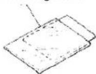
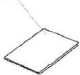
Remove the M10e from its packing container. The Top Cover is shipped unattached in a separate compartment. Check to mae sure you have the following accessory items:
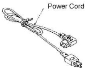
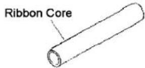
Head Cleaning Sheet
M10e Operator Manual
Careful consideration must be given when selecting the location of the printer, especially to environmental considerations. To obtain optimum results from the M10e, always try to avoid operation locations influenced by:
- Direct or bright sunlight, as this will make the label sensor less responsive and may cause the label to be sensed incorrectly.
- Locations which have extremes of temperature, as this can create electrical problems on the circuits within the printer.
- The installed location of the printer should ideally be in areas free from dust, humidity and sudden vibrations.
CONSUMABLES
Always use SATO carbon ribbons or equivalent in the thermal transfer models. The use of incorrect materials may cause malfunctions of the printer and void the warranty.
DIMENSIONS
Width: 18.7 inches 475 mm
Depth: 12.3 inches 313.4 mm
Height:, M10eTT: 12.6 inches 319.2 mm
Height, M10eDT 10.8 inches 274.2 mm
Section 2. Installation
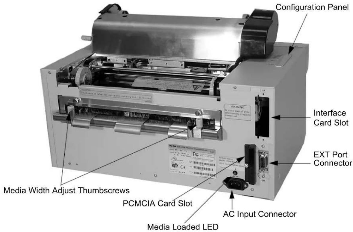
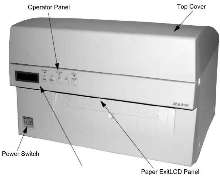
PowerSwitch To turn power On or Off
Operator Panel To set up the various configurations and to display dispensing quantity and the various alarms.
Configuration Panel Potentiometers and DIP switches to configure the printer and make setup adjustments.
AC Input Connector To input 115V 50/60 Hz. Use the power cable provided.
Interface Slot
Slot for installation of Plug-In Interface Module.
EXT Connector
This is an external signal connector external control of print cycle.
PCMCIA Card Slot Connector for Optional PCMCIA Memory Card.
Ribbon Loading (not applicable for the M10eDT)
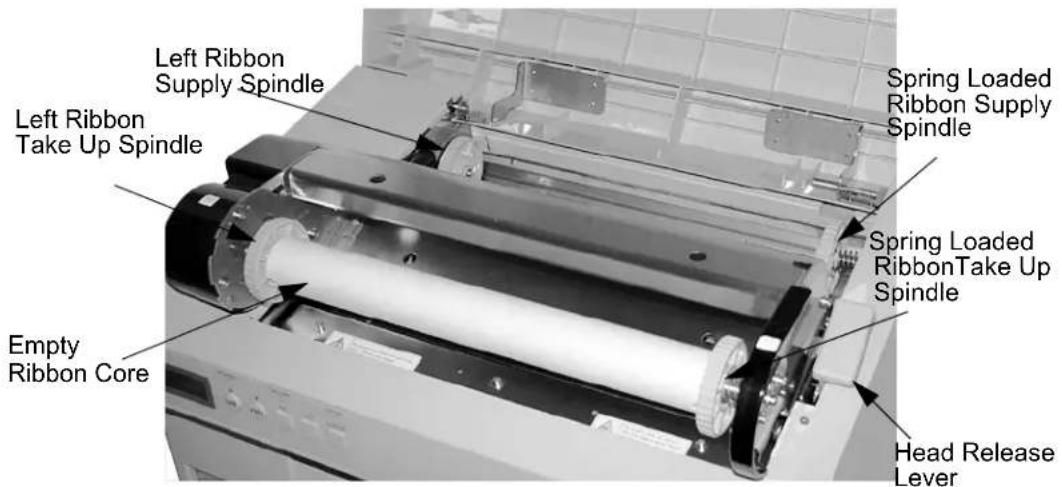
- Open the Top Cover to expose the ribbon mechanism..
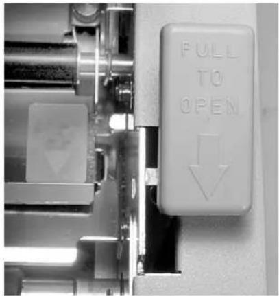
- Open the Print Head by pulling forward on the purple Head Latch lever on the right hand side of the ribbon mechanism.
- Lift the Print Head by rotating it upward and to the rear.
- The right hand Ribbon Supply Spindle is spring loaded. Press outward on the spring loaded spindle and place the new ribbon on the left hand spindle, making sure the notches in the core line up with the tangs on the spindle.
- Place the ribbon on the right hand ribbon Supply Spindle, again making sure the notches in the core line up with the tangs on the spindle. Release the spring loaded spindle.
- Route the ribbon around the Print Head and up to the take up core as shown in the ribbon loading diagram in the Top Cover.
- Place an empty ribbon core on the Ribbon Take Up Spindle. The right hand spindle is spring loaded. Press outward to provide clearance to install the core. The ribbon leader is attached to the ribbon by an adhesive strip. Carefully pull the leader free and pull about 18 inches of leader from the new ribbon. The ribbon should come off the top of the roll, ink side (dull side) down.
- Route the ribbon as shown in the Ribbon Routing Diagram on the inside of the Top Cover.
- Attach the leader to the take up core by pressing the adhesive strip on the leader firmly onto the core (if the adhesive strip does not adhere, use a small piece of tape).
- Manually wind approximately three turns of ribbon on the core.
- Inspect the ribbon to make sure it is not folded over or excessively wrinkled as it passes over the print head.
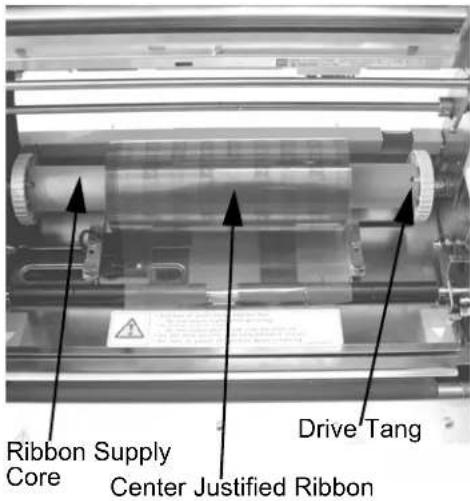
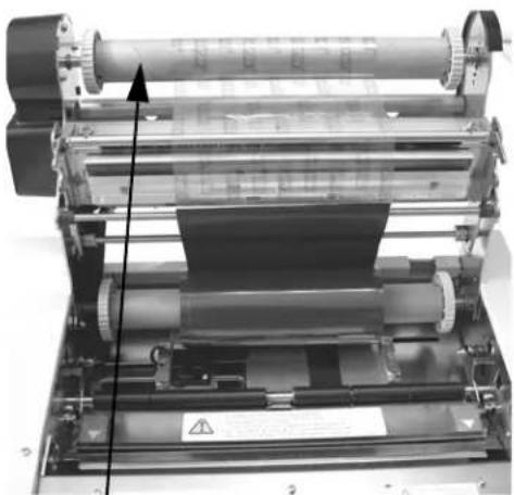
natural_image
Close-up of a mechanical printing or paper roll with visible rollers and components, no text or symbols present.Ribbon Take Up Core
Section 2. Installation
- Close the Print Head by rotating it forward and down. Press firmly on each end of the ribbon mechansim at the points labeled "PUSH" until the Print Head latches firmly in place.
Loading the Label Stock
The M10e has an automatic media loading feature, making it extremely easy to load.
-
Select the proper media sensing method using the DIP switches on the Configuration Panel. The printer comes from the factory set up for label gap detection (DS2-2 and DS3-3 both in the Off position). If Eye-Mark labels are to be used, DS2-2 should be placed in the On position.
-
Apply power to the printer.
-
Release the Print Head by pulling forward on the Head Latch Lever.
-
Check to make sure that nothing is in the media path. Remove any media that may have been left in the printer.
-
Adjust the Label Width Guides by losing the thumbscrew and moving the guides in or out to match the media width. The guides are interlocked so that adjusting one will automatically adjust the other side to maintain a center justified label path. Tighten the thumbscrews.
-
Note that the Green Media Loaded LED on the back panel is off.
-
Thread the media into the back of the printer between the label guides. When it is correctly positioned, the Green Media Loaded LED will be on.
-
Close the Top Cover.
-
Place the printer Online by pressing the LINE key.
-
The printer will automatically feed the media into the printer until it is correctly positioned for printing.
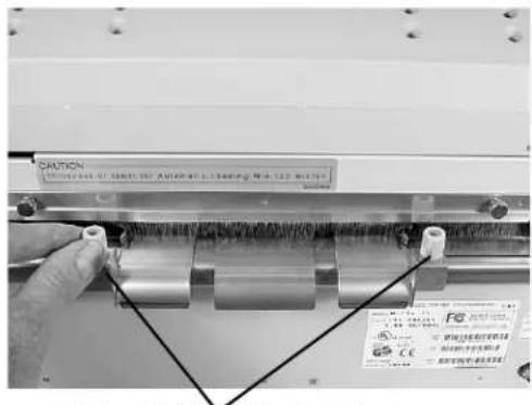
Label Width Adjustment Thumbscrews
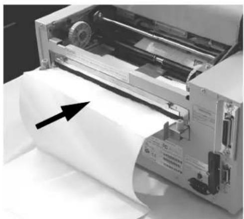
natural_image
Close-up of a printer printing paper with an arrow pointing to the page (no visible text or symbols)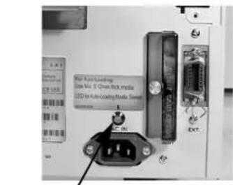
Media Loaded LED
LABEL SENSING
The M10e can position labels using either a label gap (transmissive) or an Eye-Mark (reflective) sensor. The sensor used is selected by DSW2-2. The sensor position are fixed and cannot be adjusted. In addition, the signals from the sensors can be adjusted using the LCD panel to compensate for different liner opacities and/or Eye-Mark reflectance values.
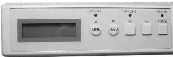
LCD Display 2 Line x 16 Character display.
POWER LED Illuminated when power is applied.
ERROR LEDs Illuminated when errors have occurred.
ON-LINE LED Illuminated when printer is On-Line.
LINE Key Switches the printer On-Line or Off-Line. It can also be used as a Pause function key to stop label during the printing process. Also used as an UP cursor control.
FEED Key To feed one blank label. When On-Line the printer will print another copy of the last label. Also used as a DOWN cursor control.
RIGHT CURSOR >> To move the cursor to the right.
LEFT CURSOR << To move the cursor to the left
ENTER Selects setting
DIP SWITCH PANEL
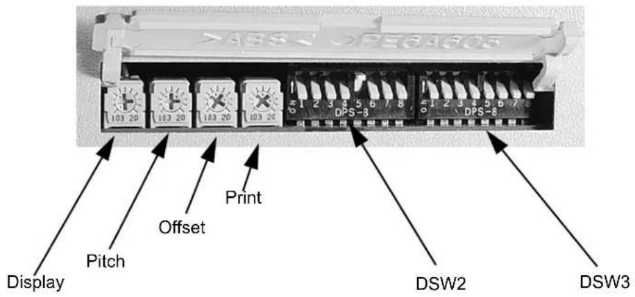
The DIP Switch panel is located inside the cover and contains two 8-position DIP switches and three adjustment potentiometers. Adjustment procedures for these are listed in Section 3: Configuration.
Section 2. Installation
This lage left intentionally blank.
SECTION 3. CONFIGURATION
PRINTER DIP SWITCH CONFIGURATION
DIP SWITCH PANELS
There are two DIP switches (DSW2 and DSW3) located on the leftside of the printer under a flip-up cover. Raise the Top Cover for access to these switches. In addition, a third DIP switch is located on the RS232C Serial Adapter card and is used to set the RS232C transmit/receive parameters. These switches can be used to set:
• Thermal transfer or direct thermal mode
- Label sensor enable/disable
- Head check mode
- Hex dump mode
- Single Job or Multi-Job Receive buffer
- Operation mode
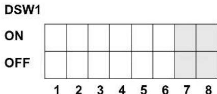
Each switch is an eight section toggle switch. The ON position is always to the left. To set the switches, first power the unit Off, then position the DIP switches. Finally, after placing the switches in the desired positions, power the printer back on. The switch settings are read by the printer electronics during the power up sequence. They will not become effective until the power is cycled.
RS232 TRANSMIT/RECEIVE SETTING
Data Bit Selection (DSW1-1). This switch sets the printer to receive either 7 or 8 bit data bits for each byte transmitted.
| DSW1-1 SETTING | |
| Off 8 Data Bits | |
| On 7 Data Bits | |
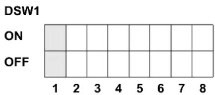
Parity Selection (DSW1-2, DSW1-3. These switches select the type of parity used for error detection.
| DSW1-1 DSW1-3 SETTING | ||
| Off Off No Parity | ||
| Off On Even | ||
| On Off Odd | ||
| On On Not Used | ||
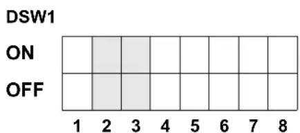
Stop Bit Selection (DSW1-4). Selects the number of stop bits to end each byte transmission.
| DSW1-4 SETTING | |
| Off 1 Stop Bit | |
| On 2 Stop Bits |
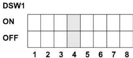
Baud Rate Selection (DSW1-5, DSW1-6). Selects the data rate (bps) for the RS232 port.
| DSW1-5 DSW1-6 SETTING | |
| Off Off 9600 | |
| Off On 19200 | |
| On Off 38400 | |
| On On 57600 | |
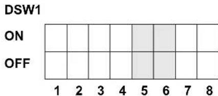
Protocol Selection (DSW1-7, DSW1-8). Selects the flow control and status reporting protocols. See Section 6: Interface Specifications for more information. (* Will select the Status 2 protocol if DSW2-8 is ON).
| DSW1-7 DSW1-8 SETTING | |
| Off Off Rdy/Bsy | |
| Off On Xon/Xoff | |
| On Off Bi-Com 3 | |
| On On Bi-Com 4 | |
PRINTER SET UP
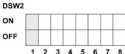
Print Mode Selection (DSW2-1). Selects between direct thermal printing on thermally sensitive paper and thermal transfer printing using a ribbon.
| DSW2-1 SETTING | |
| Off Therm Xfr | |
| On Direct Therm | |
bar
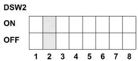
DSW2 | Category | Value | |---|---| | ON | 1 | | OFF | 1 | | 1 | 2 | | 2 | 3 | | 3 | 4 | | 4 | 5 | | 5 | 6 | | 6 | 7 | | 7 | 8 |Sensor Type Selection (DSW2-2). Selects between the use of a label gap or a reflective Eye-Mark detector.
| DSW2-2 SETTING | |
| Off Gap | |
| On Eye-Mark | |
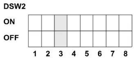
Head Check Selection (DSW2-3). When selected, the printer will check for head elements that are electrically malfunctioning.
| DSW2-3 SETTING | |
| Off Disabled | |
| On Enabled | |
Receive Buffer Selection(DSW2-5). Selects the operating mode of the receive buffer. See Section 6.Interface Specifications for more information.
| DSW2-5 SETTING | |
| Off Single Job | |
| On Multi Job | |
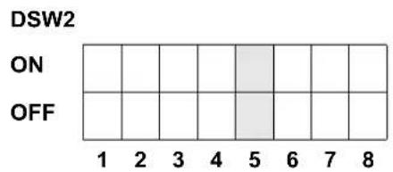
If a 10/100BaseT LAN card is installed, DS2-5 has the following definitions:
| DSW2-5 SETTING | |
| Off ENQ Response | |
| On Periodic Response | |
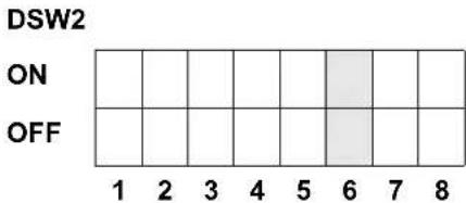
Firmware Download (DSW2-6). Places the printer in the Firmware Download mode for downloading new firmware into flash ROM.
| DSW2-6 SETTING | |
| Off Disabled | |
| On Enabled | |
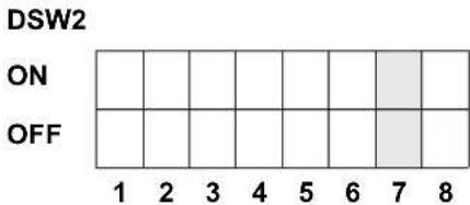
Protocol Code Selection (DSW2-7). Selects the command codes used for protocol control. Refer to page E-1 for more information.
| DSW2-7 SETTING | |
| Off Standard | |
| On Non-Std | |
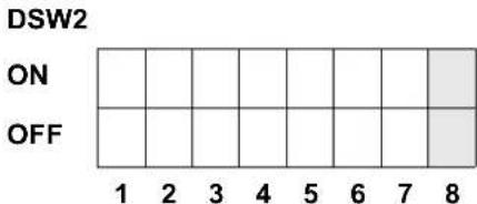
Status Select(DSW2-8). For emulating earlier series software commands. Should be used only if problems are encountered when using existing software. This switch will also affect the settings selected by DSW1-7 and DSW1-8.
| DSW2-8 SETTING | |
| Off Status 3 & | 4 Enabled |
| On Status 2 & | 3 Enabled |
Backfeed Sequence (DSW3-1, DSW3-2). Backfeed is used to correctly position the label for application and then retract the next label to the proper print position. This operation can be performed immediately after a label is printed and used, or immediately prior to the printing of the next label.
| DSW3-1 SETTING | |
| Off Off Continuous | |
| Off On Tear-Off | |
| On Off Cutter* | |
| On On Not Used |
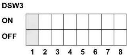
* Defaults to Continuous if cutter not installed
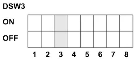
Label Sensor Selection (DSW3-3). Enables or disables the Label Sensor. If the Sensor is enabled, it will detect the edge of the label and position it automatically. If it is disabled, the positioning must be under software control using Line Feed commands.
| DSW3-3 SETTING | |
| Off Not Used | |
| On Sensor Used | |
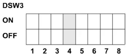
Back-Feed Selection (DSW3-4). When Back-Feed is enabled, the printer will position the last printed label for dispensing and retract it before printing the next label. The amount of backfeed offset is adjustable.
| DSW3-4 SETTING | |
| Off Disabled | |
| On Enabled | |
External Signal Interface. See Section 6: Interface Specifications for information on the External Signals.
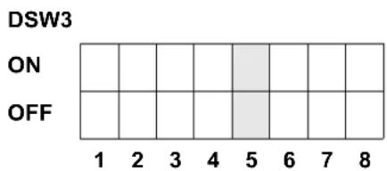
EXT Print Start Signal Selection (DSW3-5). Allows an external device to initiate a label print for synchronization with the applicator. When DSW3-5 is On, the unit is in the Continuous print mode, Backfeed is disabled and External Signals are ignored.
| DSW3-5 SETTING | |
| Off Enabled | |
| On Disabled | |
External Signal Type Selection (DSW3-6, DSW3-7). Both the polarity and signal type (level or pulse) of the external print synchronizing signal can be selected.
| DSW3-6 DSW3-7 SETTING | ||
| Off Off Type | 4 | |
| Off On Type | 3 | |
| On Off Type | 2 | |
| On On Type | 1 | |
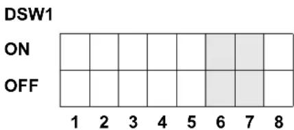
Repeat Print via External Signal (DSW3-8). Allows the applicator to reprint the current label in the print buffer.
| DSW3-8 SETTING | |
| Off Enabled | |
| On Disabled | |
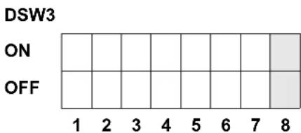
SWITCH SELECTIONS
All switches are placed in the Off default position for shipping. This will result in the following operating configuration:
Communications: 8 data bits, no parity, 1 Stop bit, 9600 Baud
Protocol: Ready/Busy
Sensor: Gap Sensor
Receive Buffer: Multi Job
Mode: Batch/continuous
Label Sensor: Sensor Used
Backfeed: Enabled
External Signals: Enabled
SOFTWARE DEFAULT SETTINGS
The printer stores the software settings upon receipt and uses them until they are again changed by receipt of a command containing a new setting. These settings are stored in non-volatile memory and are not affected by powering the printer off. The printer may be reset to use the default software settings by depressing the LINE and FEED keys simultaneously while powering the printer on. This will result in the following default configuration:
| M10e | |
| Print Darkness 3 | |
| Print Speed 4 in. per sec. | |
| Print Reference Vertical = 0000, Horizontal = 0000 | |
| Zero | Slash |
| Auto On Line | Enabled |
| Feed on Error | Enabled |
| Feed Reprint | Enabled |
| Priority | Command |
Once the default operation is completed, a DEFAULT COMPLETED message will be displayed on the LCD panel. The printer should be powered off while this message is being displayed (or after the beep is heard. This saves the default settings in the non-volatile memory where they will be automatically loaded the next time the printer is powered on.
DEFAULT COMPLETED
PITCH
After the pitch has been set with the LCD Control Panel, it is sometimes desirable to make minor adjustments. This can be done using the PITCH potentiometer on the top panel. This potentiometer is set at the factory so that it has a range of +/- 3.75 mm. The midpoint setting should have no effect on the pitch. Turning the potentiometer all the way clockwise should move the print position 3.75 mm up towards the top edge of the label. Turning it all the way counterclockwise should move the print position down 3.75 mm.
- While depressing the FEED key on the front panel, power the printer on.
- When you hear one beep from the printer, release the FEED key and the printer will display on the LCD panel a message asking what type of Test Label you want to print.
- Use the Cursor keys to step to the Configuration selection and press the ENTER key to accept the selection.
- Use the Cursor keys to select the Test Label Size. After the size is selected, press the ENTER key to accept the selection and the printer will begin to print test labels continuously.
- Adjust the PITCH potentiometer on the front panel until the first print position is at the desired location on the label. If the potentiometer does not have enough range, then you will have to change the pitch setting using the front panel display.
- Press the FEED key to stop the printer.
- To exit the Test Label mode, power the printer off and then back on.
Adjusting the PITCH potentiometer will affect the stop position of the label.
BACKFEED OFFSET
When a label is printed it must be correctly positioned for dispensing and application. The Backfeed adjustment is used to position the label so that it is fully dispensed and ready for application. It may then be necessary to reposition the next label before printing. The Backfeed (repositioning of the label) operation is enabled if DSW3-4 is in the Off position. If Backfeed is enabled, placing DSW3-1 is in the Off position will cause the backfeed operation to be performed immediately before each label is printed. If DSW3-1 is in the On position, the backfeed operation is performed as soon as the dispensed label has been printed and taken from the printer.
The amount of backfeed is controlled by the OFFSET potentiometer on the DIP Switch Panel inside the cover. When turned all the way counterclockwise, the amount of backfeed is +3.75 mm, and -3.75 mm when turned all the way counterclockwise.
- Turn the printer on.
- Press the LINE key to place the printer in the Off Line status.
- Press the FEED key to feed out a blank label.
- Adjust the position using the OFFSET potentiometer on the front control panel and feed another label by depressing the FEED key. Repeat this procedure until the label is fully released from the liner.
DISPLAY
This potentiometer is used to adjust the contrast of the LCD display for optimum viewing under various lighting conditions.
The PRINT potentiometer is used to adjust the amount of heat (i.e., power) applied to the head for printing. It provides a continuous range of adjustment. Maximum print darkness is obtained by turning the potentiometer all the way clockwise and a maximum counterclockwise setting will give the lightest print.
NOTE: The PRINT potentiometer adjustment will affect the darkness in all of the command code speed and darkness ranges.
The LCD Panel is used by the operator in conjunction with the LINE and FEED switches to manually enter printer configuration settings. Many of these settings can also be controlled via software commands and in the case of conflict between software and control panel settings, the printer will always use the last valid setting. If you load a label job that includes software settings and then enter a new setting via the LCD panel, the manually set values will be used by the printer. If you set the values manually and then download a job with software settings, the software settings will be used.
There are seven modes of operation. To enter the desired mode, the KEY SEQUENCE combination listed in the table below must be performed. The initial LCD display message is shown for each mode.
| MODE KEY SEQUENCE INITIAL DISPLAY PAGE | |||
| Normal POWER ONLINE | QTY:000000 | 3-10 | |
| Advanced LINE + POWER ADVANCED MODE | 3-13 | ||
| Test Print FEED + POWER TEST PRINT MODE | CONFIGURATION | 3-25 | |
| Default Setting LINE + FEED + POWER DEFAULT SETTING YES NO | 3-26 | ||
| Clear Non-Standard Protocol | DSW2-7 ON + LINE + FEED+ POWER | ALT. PROTOCOL | 3-27 |
| Protocol Code Download | DSW2-7 ON + POWER + LINE | USER DOWNLOAD | 3-27 |
| Hex Dump | DSW2-4 ON + POWER | ONLINE QTY:000000 | 3-28 |
NORMAL MODE
The printer initially powers on in the ONLINE mode. The user can access the User Settings using the following procedures.
V 05.00.03.00 INITIALIZING
Displays the firmware during the initialization.
ONLINE QTY:000000
The LCD will display the ONLINE status on the top line and the bottom line will contain the label quantity (QTY) status. The message will be changed to OFFLINE whenever the printer is switched offline by pressing the LINE key. As soon a print job is received, the quantify line will indicate the number of labels to be printed. As soon as the label job begins to print, the display will indicate the number of labels in the print job that remains to be printed.
OFFLINE 000000
Press the LINE key once. When the display changes to OFFLINE, press the FEED and LINE keys simultaneously for more than one second. Release the keys.
PRINT DARKNESS 1 2 3 4
The LCD now displays the Print Darkness selections. The 5 current setting is indicated by a cursor over one of the range settings. There are 5 possible selections. The lowest setting represents the lightest print and the highest setting the darkest print.
- Press the Cursor keys to step the cursor to the desired setting.
- Once the correct setting is underlined, press the ENTER key to accept the selection and step the display to the next adjustment.
PRINT SPEED 3 4 5
The print speed selections are dependent upon the printer model. The current setting is indicated by the cursor.
- Use the Cursor keys to step the cursor to the desired setting.
- Once the correct setting is selected, press the ENTER key to accept the selection and step the display to the next adjustment.
PITCH OFFSET + 00mm
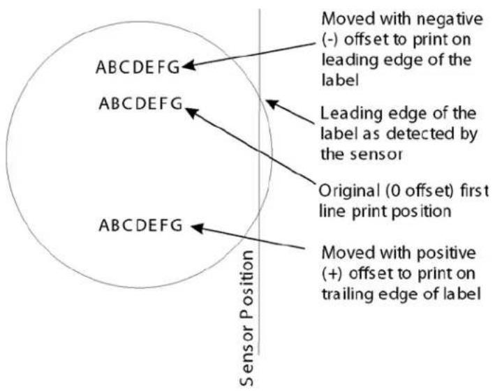
The label Pitch is the distance from the leading edge (the edge that comes out of the printer first) of a label and the leading edge of the next label. The leading edge position of the label can be adjusted relative to the print head +/- 59mm in increments of 1mm. Once the position is set, it can be fine adjusted +/-
3.75mm using the PITCH potentometer on the Adjustment Panel.
-
The cursor will initially be positioned over the Pitch Direction setting. Use the Cursor keys to step to the positive (+) or negative (-) selection. A positive selection moves the leading edge of the label forward (away from the print head) while a negative selection moves the leading edge of the label back into the mechanism.
-
Once the correct direction is selected, pressing the ENTER key will accept the setting and advance the cursor to the Offset selection.
-
Use the Cursor keys to step the first digit of the counter to the desired setting. The display will increment one step each time the Cursor keys are pressed. The maximum setting is 5.
-
Press the ENTER key to accept the setting and advance the cursor to the second digit. Again use the Cursor keys to step to the desired setting. Once it is correct, pressing the ENTER key will step to the next adjustment.
-
You may wish to print a test label after completing the adjustments to ensure they are correct.
CANCEL PRINT JOB YES NO
If the printer has a print job(s) in memory, selecting YES will cause the job(s) to be cleared. The default selection is NO. Be sure you want to cancel the print job(s) before selecting yes as the job(s) cannot be recovered and will have to be retransmitted to the printer.
- Use the Cursor keys to step the cursor to either the YES or NO selection.
- Once the correct setting is selected, pressing the ENTER key will accept the setting.
- After the print job(s) have been cleared from memory, the printer will beep 3 times and display a COMPLETED message for 3 seconds and then return to the initial ONLINE Normal Mode.
- If you wish to change any of the settings, you must enter the User Settings mode again by taking the printer OFFLINE and pressing the LINE and FEED keys.
CANCEL PRINT JOB COMPLETED
ADVANCED MODE
An Advanced Mode is provided to make adjustments that require only occasional changes. Since they affect the basic operation of the printer, the procedure for entering this mode is designed to prevent someone from accidentally changing the settings.
V 05.00.03.00 INITIALIZING
Displays the firmware during the initialization.
ADVANCED MODE The
Advance Mode is entered by pressing the LINE key while simultaneously turning power on. The printer will emit one long beep after which the LINE key is released.
ZERO SLASH YES NO
This setting determines if a zero is printed with a slash or without a slash. This setting can also be controlled via software commands. When YES is selected, the printer internal fonts will have a slash through the center of the zero character.
- Use the Cursor keys to step the cusor to either the YES or NO selection.
- Once the correct setting is selected, pressing the ENTER key will accept the setting and advance the display to the Auto Online display.
AUTO ONLINE YES NO
This setting determines the mode in which the printer powers up. If the YES selection is made, the printer powers up in the ON LINE mode and is ready to print. If NO is selected, the printer powers up in the OFF LINE mode and must be manually placed in the ON LINE mode by pressing the LINE key before it is ready to print.
- Use the Cursor keys to step the cursor to either the YES or NO selection.
- Once the correct setting is selected, pressing the ENTER key will accept the setting and advance the display to the Print Offset display.
PRINT OFFSET V:+0000 H:+0000
Vertical Offset is the distance down from the leading edge (the edge of the label that comes out of the printer first) to the first vertical print position. A positive setting moves the label edge out of the printer while making it negative moves it bsack into the printer. Horizontal Offset is distance that the label image is shifted either to the right or left on the label. The image is shifted to the left (towards the inside edge of the label) for a positive setting and it is shifted to the right (towards the outside edge of the label) for a negative setting. This setting changes the base reference point for all subsequent label jobs. It's effect is identical to the
- Use the Cursor keys to step the counter to the desired setting. The display will increment one step for each time the Cursor keys are pressed. If the LINE key is held pressed for more than two seconds, it will automatically go into the fast scroll mode.
- Once the setting is correct, pressing the ENTER key will accept the setting and advance to the next display.
Note: This setting can be overridden by the Base Reference Point Command.
SET CALENDAR YES NO
The Calendar is a optional feature in the M10e printer allowing the date and time to be set manually using the LCD Display or via the
To enable the Calendar feature, press the Cursor keys until the cursor is over the YES. If the Calendar feature is to be disabled, press the Cursor Keys key until the cursor is over the NO selection. When the desired setting is selected, press the ENTER key.
CALENDAR 00/00/00 00:00
- Year - The first display shown will have the cursor over the two digit year selection. You can scroll through the dates by pressing the LINE/FEED keys. The year number will increase by one each time the LINE key is pressed until it reaches its maximum legal value (i.e., "99" for the year digits). Pressing the FEED key will decrease the year number.
- Month - After you have set the correct year, pressing the ENTER key will advance the cursor to the two digit Month position. You can scroll through the numbers corresponding to the month by pressing the LINE key. The month number will increase by one each time the LINE key is pressed until it reaches a value of "12". Pressing the FEED key will decrease the month number.
- Day - After you have set the correct month, pressing the ENTER key will advance the cursor to the two digit Day position. You can scroll through the numbers corresponding to the month date by pressing the LINE and FEED keys. The date number will increase by one each time the LINE key is pressed until it reaches a value of "31". Pressing the FEED key will decrease the day number.
- Hour - After you have set the correct date, pressing the ENTER key will advance the cursor to the two digit Hour position. You can scroll through the numbers corresponding to the hour (using a 24 hour clock) by pressing the LINE and FEED keys. The hour number will increase by one each time the LINE key is pressed until it reaches a value of "24". Pressing the FEED key will decrease the hour number.
- Minute- After you have set the correct hour, pressing the ENTER key will advance the cursor to the two digit Minute position. You can scroll through the numbers corresponding to the hour by pressing the LINE and FEED keys. The minute number will increase by one each time the LINE key is pressed until it reaches a value of "60". Pressing the FEED key will decrease the minute number.
- After you have set the minutes, pressing the ENTER key will accept the setting and advance to the Ignore CR/LF selection.
This selection tells the printer to strip out all carriage return/line feed pairs (CR/LF) from the data stream, including graphics and 2D bar codes. It is used primarily to maintain compatibility with earlier models of SATO printers.
- Use the Cursor keys to step the underline cusor to either the YES or NO selection.
- Once the correct setting is underlined, pressing the ENTER key will accept the setting and advance the display to the Character Pitch display.
IGNORE CR/LF YES NO
CHARACTER PITCH PROP FIXED
This selection allows you to set the default character pitch to either fixed character spacing or proportional character spacing.
- Use the Cursor keys to step the cursor to the desired setting.
- Once the correct setting is selected, pressing the ENTER key will accept the setting and the display will return to the Advanced Mode display.
ADVANCED MODE To ex
it the Advanced mode, power the printer off and then back on.
CARD MODE
The Card Mode allows the operator to manage the Expanded Memory (PCMCIA Card or Internal Expanded Flash ROM).
V 05.00.03.00 INITIALIZING
Displays the firmware during the initialization.
ADVANCED MODE The
Card Mode is entered from the Advanced Mode display by pressing the Right Cursor key (>>)once.
CARD MODE The Card
Mode display indicates that the printer is in the Card Mode. To advance to the first selection, press the ENTER key.
MEM SELECT (CC1) CARD MEMORY
This selection determines which type of optional expanded memory will be addressed as "CC1" in the command streams. The CARD selection specifies the optional PCMCIA card as CC1 and the optional Expanded Flash ROM as CC2. The Memory selection specifies the optional Expanded Flash ROM as CC1 and the optional PCMCIA card as CC2.
- Step the cursor to the desired selection using the Cursor keys.
- Once the cursor is positioned over the desired selection, press the ENTER key to accept the selection and advance the display.
CARD->MEMORYCOPY TRUETYPEFONT Y/N
This selection allows you to copy TrueType fonts from the PCMCIA Memory card installed in the Memory Card slot on the rear of the printer to the optional Flash ROM.
- Use the Cursor Keys to step the cursor to desired setting. If Yes is selected, the printer will enter the Card Copy mode. If No is selected, the display will advance to the Card to Memory SATO Font Copy mode.
COPY START YES NO
- Confirm your selection by stepping the cursor to the Yes selection. If you select No, the display will return to the previous selection.
TRUETYPEFONTCOPY COPYING
- Press the ENTER key to accept the selection. If Yes was selected the copy process will start.
TRUETYPE FONTCOPY COMPLETED
- Once the copy process is completed, press the ENTER key to step the display.
CARD COPY/FORMAT XXXXXXXX ERROR
- If an error is encountered in the copy process, one of the following messages will be displayed on the second line: R/W Error Indicates a Read/Write error occurred No Card Error Indicates no card was recognized Mem Full Error Indicates that there is insufficient memory available.
CARD->MEMORYCOPY SATOFONT Y/N
This selection allows you to copy SATO fonts from the PCMCIA Memory card installed in the Memory Card slot on the rear of the printer to the optional Flash ROM.
- Use the Cursor keys to step the cursor to desired setting. If Yes is selected, the printer will enter the Card Copy mode. If No is selected, the display will advance to the Card to Memory Copy All mode.
COPY START YES NO
- Confirm your selection by stepping the cursor to the Yes selection. If you select No, the display will return to the previous selection.
SATO FONT COPY COPYING
- Press the ENTER key to accept the selection. If Yes was selected the copy process will start
SATO FONT COPY COMPLETED
- Once the copy process is completed, press the ENTER key to step the display.
CARD COPY/FORMAT XXXXXXXX ERROR
- If an error is encountered in the copy process, one of the following messages will be displayed on the second line: R/W Error Indicates a Read/Write error occurred No Card Error Indicates no card was recognized Mem Full Error Indicates that there is insufficient memory available.
MEMORY->CARDCOPY ALL <0MB> Y/N
This selection allows you to copy the entire contents from the PCMCIA Memory card installed in the Memory Card slot on the rear of the printer to the optional internal Expanded Memory.
- Use the Cursor keys to step the cursor to desired setting. If Yes is selected, the printer will enter the Card Copy mode. If No is selected, the display will advance to the Card to Memory Copy All mode.
COPY START YES NO
- Confirm your selection by stepping the cursor to the Yes selection. If you select No, the display will return to the previous selection.
| CARD->MEMORY COPY COPYING | 3. Press the ENTER key to accept the selection. If Yes was selected the copy process will start |
| CARD->MEMORYCOPY COMPLETED | 4. Once the copy process is completed, press the ENTER key to step the display. |
| CARD COPY/FORMAT XXXXXXX ERROR | 5. If an error is encountered in the copy process, one of the following messages will be displayed on the second line: R/W Error Indicates a Read/Write error occurred No Card Error Indicates no card was recognized Mem Full Error Indicates that there is insufficient memory available. |
| MEMORY->CARDCOPY ALL <0MB> Y/N | This selection allows you to copy the entire contents of the optional Expanded Memory to the PCMCIA Memory card installed in the Memory Card slot on the rear of the printer.1. Use the Cursor keys to step the cursor to desired setting. If Yes is selected, the printer will enter the Card Copy mode. If No is selected, the display will advance to the Card to Memory Copy All mode. |
| COPY START YES NO | 2. Confirm your selection by stepping the cursor to the Yes selection. If you select No, the display will return to the previous selection. |
| MEMORY->CARDCOPY COPYING | 3. Press the ENTER key to accept the selection. If Yes was selected the copy process will start |
| MEMORY->CARDCOPY COMPLETED | 4. Once the copy process is completed, press the ENTER key to step the display. |
| CARD COPY/FORMAT XXXXXXX ERROR | 5. If an error is encountered in the copy process, one of the following messages will be displayed on the second line: R/W Error Indicates a Read/Write error occurred No Card Error Indicates no card was recognized Mem Full Error Indicates that there is insufficient memory available. |
| CARD->MEMORYCOPY PROGRAM Y/N | This selection allows the user to copy printer firmware from the PCMCIA Memory Card to the printer.1. Use the Cursor keys to step the cursor to desired setting. If Yes is selected, the printer will enter the Card Copy mode. If No is selected, the display will advance to the mode display. |
| COPY START YES NO | 2. Confirm your selection by stepping the cursor to the Yes selection. If you select No, the display will return to the previous selection. |
CARD->MEMORY COPY COPYING
CARD->MEMORYCOPY COMPLETED
CARD COPY/FORMAT XXXXXXXX ERROR
-
Press the ENTER key to accept the selection. If Yes was selected the copy process will start
-
Once the copy process is completed, press the ENTER key to step the display.
-
If an error is encountered in the copy process, one of the following messages will be displayed on the second line: R/W Error Indicates a Read/Write error occurred No Card Error Indicates no card was recognized Mem Full Error Indicates that there is insufficient memory available.
MEMORY->CARDCOPY PROGRAM Y/N
This selection allows the user to copy the current firmware installed in the printer to a PCMCIA Memory Card.
COPY START YES NO
- Use the Cursor keys to step the cursor to desired setting. If Yes is selected, the printer will enter the Card Copy mode. If No is selected, the display will advance to the mode display.
MEMORY->CARDCOPY COMPLETED
-
Press the ENTER key to accept the selection. If Yes was selected the copy process will start. If you select No, the display will return to the previous selection.
-
Once the copy process is completed, press the ENTER key to step the display.
CARD COPY/FORMAT XXXXXXXX ERROR
- If an error is encountered in the copy process, one of the following messages will be displayed on the second line: R/W Error Indicates a Read/Write error occurred No Card Error Indicates no card was recognized Mem Full Error Indicates that there is insufficient memory available.
CARD FORMAT YES NO
Before a PCMCIA card can be used, it must be formatted.
Note: Formatting a card destroys all data currently stored on the card.
- Use the Cursor keys to step the cursor to desired setting. If Yes is selected, the printer will enter the Card Format mode. If No is selected, the display will advance to the mode display.
MEMORY FORMAT YES NO
Before the internal Expanded Memory can be used, it must be formatted.
Note: Formatting the Memory will destroy any stored data.
- Use the Cursor keys to step the cursor to desired setting. If Yes is selected, the printer will enter the Memory Format mode. If No is selected, the display will advance to the mode display.
CARD MODE To exit the
Card Mode, power the printer off and then back on.
SERVICE MODE
The Service Mode allows the operator to set up the basic operation parameters of the printer.
V 05.00.03.00 INITIALIZING
Displays the firmware during the initialization.
ADVANCED MODE The
Service Mode is entered from the Advanced Mode display by pressing the Right Cursor (>>)key once.
SERVICE MODE
The Service Mode display indicates that the printer is in the Card Mode. To advance to the first selection, press the ENTER key.
GAP [X.XXV] INPUT [X.XV]
The M10e printers determine the location of the leading edge of the label by measuring the difference between light levels when it sees either a label edge or a black "EYE" mark. This adjustment allows you to manually set the threshold voltage level, between the maximum and minimum light levels. DIP switch DSW2-2 selects the sensor type. If DSW2-2 is in the OFF position, the setting will be for a See-Thru (or Gap) sensor and the LCD will display "GAP" on the top line along with the current setting. If DSW2-2 is in the ON position, the LCD will display "EYE" on the top line with its current setting. If the value entered for the bottom line setting is "0.0V", then the printer will automatically calculate the setting when the first label is fed after the printer is powered on or the head is closed. There are some instances where the automatically calculated value must be adjusted to ensure reliable label feeding, such as when the backing opacity or the reflectance of the EYE mark varies significantly within a roll of labels or between label rolls. In these instances the value should be set using the following procedures.
GAP [X.XXV]
INPUT [X.XV]
GAP - When setting the "gap" threshold, the voltage shown on the top line of the display must be measured with nothing but the backing in the sensor and then again with a label still attached to the backing. The formula to be used for setting the threshold is:
(High Voltage Level + Low Voltage Level) x 0.5 = Start Value
- Insert a label still attached to the backing into the sensor and close the Label Hold-Down. Record the voltage shown on the top line of the LCD panel. This line should have the message "GAP" on the top line (DIP switch DSW2-2 = OFF). Make sure the label is all the way under the sensor.
- Strip the label from the backing and insert the backing strip under the sensor and close the Label Lid. Record the voltage shown on the top line of the LCD panel. The voltage ranges measured should be within the following ranges:
Backing with label = 2.0V to 3.5V
Backing without label = Less than 1.0V
If the measured values are outside this range, you may have trouble in finding a value that will work properly under all conditions. If this is the case, a higher quality label may be needed to get adequate performance.
- Calculate the starting point voltage using the formula.
- Use the LINE and FEED keys to step the counter to the desired setting. The reading will advance to a setting of 4.9 (the maximum voltage). If a value of "0.0" is set, the printer will automatically set the level each time the printer is powered on with labels loaded and the head is closed.
- Once the setting is correct, pressing the ENTER key will accept the setting and advance the next display.
EYE [X.XXV] INPUT [X.XV]
EYE - When setting the "eye" threshold, the voltage must be measured with nothing but the label under the sensor and then again with the printed "eye" mark under the sensor. The formula for this is:
(High Voltage Level + Low Voltage Level) x 0.5 = Start Value
- Insert a label into the sensor and close the Label Hold-Down. Make sure the printed "eye" mark is not under the sensor. Record the voltage shown on the top line of the LCD panel. This line should have the message "EYE" on the top line (DIP switch DSW2-2 = ON).
- Now pull the label forward until the "eye" mark is positioned under the sensor (the voltage reading should be at its highest point). Record the voltage shown on the top line of the LCD panel. The voltage ranges measured should be within the following ranges:
Eye-Mark = 2.5V to 3.5V
Label Only = Less than 1.0V
If the measured values are outside this range, you may have trouble in finding a value that will work properly under all conditions. If this is the case, a higher quality label may be needed to get adequate performance.
- Calculate the starting point voltage using the formula.
- Use the LINE and FEED keys to step the counter to the desired setting. The reading will advance to a setting of 4.9 (the maximum voltage). If a value of "0.0" is set, the printer will automatically set the level each time the printer is powered on with labels loaded or the head is closed.
- Once the setting is correct, pressing the ENTER key will accept the setting and advance to the next display.
This selection specifies whether or not the printer will feed a label when it is placed in the Online mode.
- Use the Cursor keys to step the cursor to desired setting. If Yes is selected, the printer will feed a blank label anytime it enters the Online mode.
- Once the setting is correct, pressing the ENTER key will accept the setting and advance to the next display.
This selection specifies whether or not the printer will feed a label when an error condition is cleared..
- Use the Cursor keys to step the cursor to desired setting. If Yes is selected, the printer will feed a blank label anytime an error condition is cleared.
- Once the setting is correct, pressing the ENTER key will accept the setting and advance to the next display.
AUTO ONLINE FEED YES NO
FEED ON ERROR YES NO
REPRINT W/FEED YES NO
This selection specifies whether or not the printer will print the last printed label stored in memory when the FEED key is pressed in the Normal Online mode.
- Use the Cursor keys to step the cursor to desired setting. If Yes is selected, the printer will reprint the last label when the FEED key is pressed when the printer is Online. If the printer is Offline, pressing the FEED key will feed a blank label.
- Once the setting is correct, pressing the ENTER key will accept the setting and advance to the
FORWARD/BACKFEED DISTANCE DEFAULT
This display will only appear Backfeed is enabled (DSW3-4 = OFF). The maximum backfeed distance is 255 mm.
- Use the Cursor keys to select either the Default or the Manual selection.
- Once the setting is correct, pressing the ENTER key will accept the setting and advance to the next display.
FORWARD/BACKFEED DISTANCE XXXmm
-
If Manual setting is selected, use the Cursor keys to advance the distance to the desired setting. Each time the LINE key is pressed, the Distance will advance 1 mm. The maximum distance is 255 mm.
-
Once the desired distance is set, press the ENTER key to accept the setting and step to the next display.
EXT PIN 9 SELECT MODE1 MODE2
This selection allows the user to select the conditions that cause the signal on Pin 9 of the EXT connector to be true. If Mode1 is selected, pin 9 will be true when the printer is ready to print, i.e. it is Online and has a print job loaded (a quantity of labels to be printed on the display). If Mode 2 is selected, pin 9 will be true if the printer is Online.
- Use the Cursor keys y to step the cursor to the desired setting.
- Once the desired setting is selected, press the ENTER key to accept the setting and step to the next display.
EURO CODE D5
This selection allows the user to specify the dexadecimal code for the character which is replaced with the Euro Character. The default is D5H.
- The cursor should be positioned over the first digit selection. Use the Cursor keys to step to the desired setting.
- Press the ENTER key to advance the cursor to the second digit of the desired hexadecimal code.
- Press the LINE key to step to the desired setting.
- When the setting is correct, press the ENTER key to accept the setting and step to the next display.
| SELECT LANGUAGE ENGLISH | This selection allows the user to select the character set used by the printer. The selections are English, French, German, Spanish, Italian and Portuguese.1. Press the Cursor keys to advance to the desired language setting.2. When the setting is correct, press the ENTER key to accept the setting and step to the next display. |
| IGNORE CAN/DLE YES NO | If the printer is placed in the Multi-Item Buffer Mode (DSW2-5 = OFF), the user can chose to ignore CAN (18H) and DLE (10H) commands used in bi-directional communications (see Section 6: Interface Specifications). If the Single Item Buffer Mode is chosen (DSW2-5 = ON), this display will be skipped. |
| PRIORITY SETTING COMMAND LCD | This selection allows the user to assign a priority for Print Darkenss, Print Speed and Print Offset setting methods. If LCD is selected, the setting established via the LCD display/menu system will be used for an incoming label job, regardless of any different command settings. If Command is selected, any commands in the label job will take precedence and be used for printing the job.1. Use the Cursor keys to step to the desired priority.Once the desired setting is selected, press the ENTER key to accept the setting and step to the next display. |
| LABEL RE-DETECT ENABLE DISABLE | This selection allows the user to disable the feeding of a blank label upon power up. If Enable is selected, the printer will automatically feed a label until it detects a label enge. This will correctly position the next printed label under the print head. If Disable is selected, the printer will not try to detect the next label and the operator is responsible for ensuring that the label is correctly positioned before printing.1. Use the Cursor keys to step to the desired setting.Once the desired setting is selected, press the ENTER key to accept the setting and step to the next display. |
| IEEE1284 ACK SIGNAL 00.5 | If the printer is placed in the Single Item Buffer Mode (DSW2-5 = ON), this selection allows the user to set the width of the IEEE1284 ACK pulse. In the Multi-Item Buffer Mode, this display will be skipped.The range is 0.5 μsec to 10 μsec.1. Use the Cursor keys to step the display to the desired setting. The setting will advance in increments of 0.1 μsec each time the LINE key is pressed until the setting reaches 10.0 μsec when it will wrap around to the 0.5 μsec setting.Once the desired setting is selected, press the ENTER key to accept the setting and step to the next display. |
| SERVICE MODE The Service mode is exited by powering the printer off and then back on. | |
COUNTERS MODE
The Counters Mode is provided to allow the user to access the internal printer cousters.
ADVANCED MODE The
Counter Mode is accessed from the Advanced Mode. Press the Cursor keys to step to the Counter Mode.
COUNTERS MODE
Pressing the ENTER key will advance the display to the counter selections.
COUNTERS HD CUT
The counters are identified in the display as:HD:Head Counter (should be reset when print head is replaced)
HD: Head Counter
CUT: Cutter Counter
LIFE: Life Counter (cannot be reset)
- Use the Cursor keys to step the cursor to the desired counter, the Head (HD) counter or the LIFE counter. The default position is the Head Counter. Use the Cursor keys to advance the cursor to the desired selection.
HEAD COUNTER 0.5M
-
Once the correct setting is selected, pressing the ENTER key will display the current value (in meters) stored in the counter. The maximum number of digits displayed is 8.
-
Pressing the ENTER key again will advance the counter to the Clear mode. All counters with the exception of the LIFE counter may be cleared.
HEAD COUNT CLEAR YES NO
- Use the Cursor keys to select the desired setting. If you only wanted to read the counter value, select NO. If you want to read the counter and reset it to 0.0, place the cursor over the YES. Once the desired setting is selected, pressing the ENTER key will advance the return you to the Counters Mode display.
COUNTERS MODE 5. To
exit the Counters Mode, turn power to the printer off and then back on.
TEST PRINT MODE
The Test Print Mode offers 4 different status labels for troubleshooting. If DSW3-5 is in the OFF position, the Test Print cycle must be initiated with a Print Start signal on the EXT connector You enter the Test Print Mode by pressing the FEED key while powering the printer on..
V 05.00.03.00 INITIALIZING
Displays the firmware during the initialization.
TEST PRINT MODE CONFIGURATION
This option allows you to print a test label. It is recommended that you print a test label after you have changed any of the settings in the Advanced Mode. The test label allows you to verify that you indeed did make the desired changes. To enter the Test Print Mode, power the printer on while pressing the FEED key. The printer will beep. Release the FEED key and the printer will display the following message on the LCD panel:
- Use the Cursor keys to step the cursor to type of test label you wish to print. The choices are:
CONFIGURATION
BARCODE
HEADCHECK
MEMORY
FACTORY
TEST PRINT SIZE 10 CM
Note: This screen will not be displayed for the Memory Test Label.
Once you have selected the type of test label to be printed, use the ENTER key to accept the selection and the display advances to the Test Print Size display. This display allows you to select the label width.
- Use the LINE key to select the lable width. Each time the LINE key is pressed, the label size advances 1 cm until it reaches a maximum width of 26 cm, at which point it will wrap to the smallest size of 13 cm.
PRESS FEED KEY TO STOP PRINTING
- Pressing the ENTER key accepts the selection.
- Press the FEED key to start printing test labels continuously.
- Press the FEED key to stop the printer.
- To exit the Test Print Mode, power the printer off and then back on.
DEFAULT SETTING MODE
Occasionally it is desirable to reset all printer configuration settings to their original default conditions. This allows the operator to start reconfiguration of the printer starting from a know set of conditions.
V 05.00.03.00 INITIALIZING
Displays the firmware during the initialization.
DEFAULT SETTING YES NO
You enter the Default Setting Mode by pressing the LINE and FEED keys while simultaneously powering the printer on. The printer will emit one long beep after which the FEED and LINE keys should be released.
- Use Cursor keys to select either the YES or NO.
- Once the desired setting is selected, pressing the ENTER key will accept the selection and the printer will reset to the original default conditions.
DEFAULT SETTING COMPLETED
- When the printer has completed the reset process it will beep 3 times and the Default Setting Completed display will appear. At this time the printer is in the default configuration.
- To exit the Default Setting Mode, power the printer off and then back on.
CLEAR NON-STANDARD PROTOCOL
The standard protocol codes used by the printer can be modified to accommodate the requirements of different host systems. However, if the printer is to be used with a system that does not use the custom protocol codes, they can be cleared and the default protocol codes reactivated. The default values are: STX = 7BH, ETX = 7DH, ESC = 5EH, ENQ = 40H, NULL = 7EH, CAN = 21H and OFFLINE = 5DH.
V 05.00.03.00 INITIALIZING
Displays the firmware during the initialization.
ALT.PROTOCOL DEFAULT COMPLETE
To Clear Non-Standard protocol codes, DSW2-7 is placed in the On position and the printer powered on while simultaneously pressing the LINE and FEED keys.
The printer will emit one long beep at which time the LINE and FEED keys should be released.
When the keys are released, the printer will replace the Alternate protocol codes with the default values.
After the default setting is complete, the printer will emit two short beeps indicating the process is complete.
To exit the mode, power the printer off and then back on.
DOWNLOAD USER DEFINED PROTOCOL CODES
The user can define a set of custom protocol codes and download them to the printer using the
V 05.00.03.00 INITIALIZING
Displays the firmware during the initialization.
USER DOWNLOAD PRESS THE LINE KEY
To enter the User Download mode, DSW2-7 is placed in the on position and the printer is powered on while simultaneously pressing the LINE key. The printer will emit one long beep after which the LINE key is released.
- Set DSW2-7 Off to replace the Standard protocol codes or On to replace the Alternate set of protocol codes.
USER DOWNLOAD WAITING
- Press the LINE key. The printer is now waiting for the data to be sent.
- Transmit the download data command stream to the printer.
- After the data has been received, the printer will beep and print a status label. If it does not beep and print a status label, the printer did not accept the data.
- If the printer did not beep and print a status label, turn the printer off and check your data stream for errors and start the download process over.
- If the custom codes are correct, press the ENTER key to accept them and terminate the download process. If they are incorrect, turn the printer off without pressing the ENTER key and begin the process again.
HEX DUMP MODE
In addition to the Test Print Labels, the printer can print the contents of the receive buffer in a hexadecimal format to allow the data stream to be examined for errors and troubleshooting.
V 05.00.03.00 INITIALIZING
Displays the firmware during the initialization.
ONLINE QTY:000000
The Hex Dump Mode is entered by placing DSW2-4 in the on position and powering the printer on.
- The printer is now ready to receive data.
- Send the data stream to the printer.
- The received data will be printed in a hexadecimal format4. To return the printer to normal operation, place DSW2-4 in the off position and power the printer off and then back on.
00000000 1B411B483031301B 56303130301B4C30 ^e H010 ^e V0100 ^e L0 00000010 3230331B57423153 41544F20414D4552 203 ^e WB1SATO AMER 00000020 4943411B48303130 1B563235301B5742 ICA ^e H010 ^e V250 ^e WB 00000030 314D2D3834303052 560D0A1B48303130 1M-8400RV ^e H010 00000040 1B563430301B4C30 3230331B57423122 ^e V400 ^e L0203 ^e WB1" 00000050 4845582044554D50 2220434F4D4D414E HEX DUMP ^e COMMAN 00000060 441851311B5A D ^f Q1 ^e Z
SECTION 4. CLEANING AND MAINTENANCE
INTRODUCTION
The following information is presented in this section:
- Adjusting the Print Quality
• Cleaning the Print Head, Platen and Rollers - Replacing the Print Head
- Replacing the Fuse
ADJUSTING THE PRINT QUALITY
One of the nice features of the SATO printers are their high print quality. They are equipped with two different methods of adjusting the quality of the print; print darkness and speed. When adjusting for optimum print quality, a bar code verifier system should be used. The human eye is a poor judge of the relative widths of the bars in a symbol, a characteristic that is extremely important for good bar code quality.
PRINT (DARKNESS)
This adjustment allows the user to control (within a specified range) the amount of power that is used to activate the individual print head heat elements. It is important to find a proper print darkness level based on your particular label and ribbon combination. The printed images should not be too light nor should the ink from the ribbon “bleed.” The edges of each image should be crisp and well defined.
The Print Darkness can be set using the front panel LCD panel or by downloading the setting using the Print Darkness software command. Once the range has been selected, the PRINT Potentiometer on the front panel can be used to make finer adjustments.
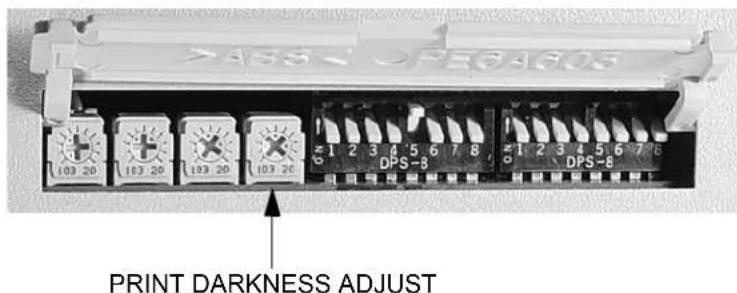
The primary adjustment for Print Darkness is the PRINT potentiometer on the Configuration DIP Switch panel. It provides a continuous range of adjustment, allowing you to make precise changes. Use a small cross-point screwdriver, turning clockwise for darker print and counterclockwise for lighter print.
NOTE: The PRINT potentiometer adjustment will affect the darkness in all of the command code speed ranges, i.e. if the PRINT potentiometer is adjusted for lighter print, the darkness will be lighter in all speed ranges selected by the command code.
PRINT SPEED
The other method of controlling print quality is by controlling the speed at which the label is printed. This adjustment is made only on an individual label basis using the Print Speed command code. For more details on this command, see the “e” Printer Programming Reference. Changing the print speed allows the user to control the amount of time allowed for print element cooling before the media is stepped to the next print position. It is especially critical when printing “ladder” bar codes (bar codes printed with the bars parallel to the print line). When printing a “ladder” bar code, it is important to allow the head to cool sufficiently before stepping to the next position. If it does not have sufficient time to cool, the bar will be “smeared” on the trailing edge.
The Print Speed can be set using the LCD panel or with the Print Speed software command. The software command will override the any setting entered using the LCD panel. The other method of controlling print quality is by controlling the speed at which the label is printed. This adjustment is made only on an individual label basis using the Print Speed command code. For more details on this command, see the “e” Printer Programming Reference.
CLEANING THE PRINT HEAD, PLATEN AND ROLLERS
Supplies needed: SATO SA070 Cleaning Kit
Cleaning the Print Head
- Turn the printer off.
- Open the Top Cover.
-
Open the Print Head Assembly by pulling the Head Latch toward the front of the printer. The Print Head Assembly is spring-loaded and will automatically open as soon as the Head Latch is disengaged. Rotate the Print Head Assembly up and to the rear to give access to the underside of the print head.
-
Remove the ribbon (M10eTT only)
-
Apply SATO Thermal Print Head Cleaner to a cotton swab.
-
The Print Head faces downward along the front edge of the assembly. Pass the end of the dampened swab along the epoxy ridge that runs the entire width of the Print Head.
-
Check for any black coloring or adhesive on the swab after cleaning.
-
Repeat if necessary until the swab is clean after it is passed over the head.
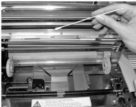
- The head should be cleaned at least every time the ribbon is changed and more often in dusty environments.
Cleaning the Platen and Rollers
- Turn the printer off.
- Open Top Cover.
-
Open the Print Head Assembly by pulling the Head Latch toward the front of the printer. The Print Head Assembly is spring-loaded and will automatically open as soon as the Head Latch is disengaged. Rotate the Print Head Assembly up and to the rear to give access to the Platen.
-
Lift up on both ends of the Label Cover Plate at the points marked with the purple arrows until it releases.
-
Apply SATO Thermal Print Head Cleaner to one of the cotton swabs.
-
The Platen is the rubber roller directly below the Print Head. It should be cleaned of any ribbon or label residue.
-
The Label Feed Rollers are located to the rear of the Print Head Assembly. They should be cleaned of any label residue or foreign material.
-
Repeat if necessary. The platen and rollers should be cleaned whenever foreign matter such as dust or adhesive is present.
-
Reposition the Label Cover Plate and press down at the points marked with the purple arrows until it snaps in place.
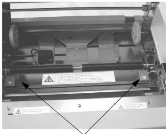
Lift Label Plate at arrows to give access to label rollers.
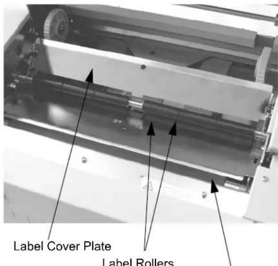
Platen
CLEANING THE LABEL EDGE AND PAPER END SENSORS
There are two sensors that are used to control the positioning of the label. One is a transmissive see-thru sensor that detects the edge of the label by looking through the backing paper which is translucent and detecting the presence of the opaque label. Another is a reflective sensor that detects the light reflected from the bottom of the label liner. When a
printed black Eye-Mark passes through the beam, the light is no longer reflected back to the sensor detector, indicating to the printer that it should use this position as the start of a new label. When dust, dirt, adhesive or other foreign matter interferes with the light path of either of these sensors, the results is erratic label positioning and feeding. These sensors should be cleaned regularly, at least every two rolls of labels. In addition, a Paper End sensor is used to detect when the media supply has been depleted. It is very important that this sensor be kept operating properly since the Print Head depends upon the presence of the media as a heat sink. Printing without media under the head can result in damage to the Print Head.
Supplies Needed: SATO SA070 Cleaning Kit
- Turn the printer off.
- Open the Top Cover.
- Unlatch the Print Head Assembly and remove any labels remaining in the printer.
- Remove the ribbon (M10eTT only).
- The Label Edge Senors are located in the paper path behind the Print Head. See Section 2:Installation for their location relative to the Print Head. They are automatically positioned when the the Label Width Guides are adjusted.
- Remove the thumbscrew holding the Sensor Housing.
- Apply SATO Thermal Print Head Cleaner to one of the cotton swabs.
- Use the cotton swab to clean any foreign matter from the exposed surface of the sensors.
- Reposition the Sensor on the adjustable paper guide and replace the thumbscrew.
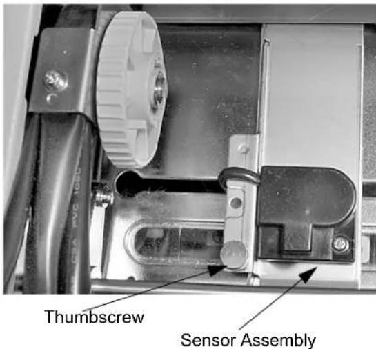
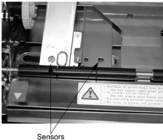
In addition, there is one more sensor to sense when the media is correctly positioned for auto loading. When dust, dirt, adhesive or other foreign matter interferes with the light path of this sensors, the results is erratic paper end error signals. This sensors should be cleaned regularly, at least every two rolls of labels.
Supplies Needed: SATO SA070 Cleaning Kit
- Turn the printer off.
- Open the Top Cover.
- Release the Print Head by pulling forward on the Head Release Latch
- Lift up on both ends of the Label Cover Plate at the points marked with the purple arrows until it releases.
- Apply SATO Thermal Print Head Cleaner to one of the cotton swabs.
- The sensor is located underneath the label plate..
- Use the cotton swab to clean any foreign matter from the exposed surface of the sensors.
- Reposition the Label Cover Plate and press down at the points marked with the purple arrows until it snaps in place.
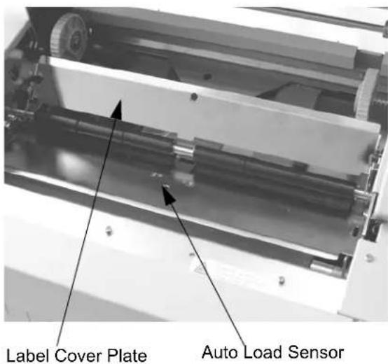
The print head is a user-replaceable item. If it becomes damaged for any reason, it can be easily removed and replaced. Contact your local SATO representative for information on obtaining a new print head.
Supplies needed: Flat Blade Screwdriver (Note: Some units may require a No. 2 Phillips screwdriver)
- Turn the printer off and remove the power cable.
- Open the Top Cover.
- Unlatch the Print Head by pulling forward on the Head Release Lever.
- Remove the ribbon (M10eTT only).
- View the Print Head Assembly from the front of the printer. Locate the center mounting screw on the top of the assembly. Remove this screw and set it aside.
- The Print Head should now be loosened from the top of the assembly by grasping either side and carefully pulling it down and forward.
- Disconnect the signal and power cables from the print head connectors and set the Print Head aside.
- Carefully attach the new print head to the connectors, using caution to make sure the connector keys are correctly positioned.
NOTE: Be careful not to scratch the printing surface of the print head while installing it.
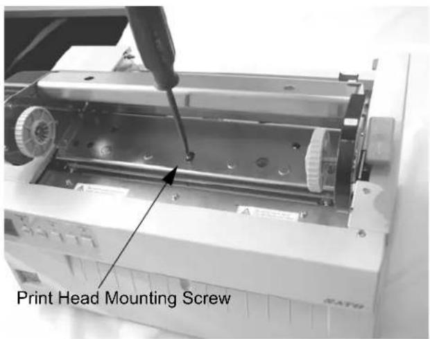
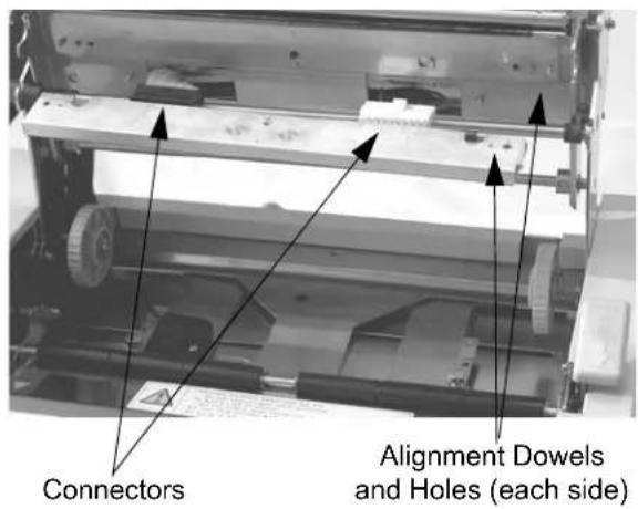
Scratching the surface will cause permanent and irreparable damage and is not covered by the warranty!
- Reposition the Print Head in the printer, taking care to line ups the alignment dowels on each end of the Print Head with the corresponding holes in the Print Head Mounting Bracket.
- Locate the mounting screw in the top plate assembly and align it with the tapped hole in the new print head.
- Re-secure the print head by tightening the screw.
SECTION 5. TROUBLESHOOTING
This section has been devised to help you if you are unable to produce output on the M10e printers. Use this section to make sure the basics have been checked before deciding you are unable to proceed any further. The section is divided into five parts:
- Initial Checklist
• IEEE1284 Parallel Interface
• RS232C Serial Interface
• Universal Serial Bus Interface
• LAN Ethernet Interface
INITIAL CHECKLIST
- Is the printer powered up and ON-LINE?
- Is the ERROR light on the front panel off? Is this light is on, it may mean the Print Head Assembly or the Label Hold-Down is not closed and latched in position.
- Are the LABEL and RIBBON lights on the front panel off? If these lights are on, the labels or ribbons may be incorrectly loaded.
USING THE IEEE1284 PARALLEL INTERFACE
- Is the IEEE1284 printer cable connected securely to your parallel port (DB-25S Female) on the PC and to the Parallel Interface connector on the printer?
WARNING: Never connect or disconnect interface cables (or use a switch box) with power applied to either the printer or the host. This may cause damage to the interface circuitry and is not covered by warranty. - Does the Parallel interface cable used meet IEEE1284 specifications? If it does not and you are connected to an IEEE1284 or ECP parallel port on the computer, the printer may not be able to communicate correctly.
- Is there more than one parallel interface port on your PC (LPT1, LPT2, etc.)? If so, make sure you are sending data out the correct port.
- Is the IEEE1284 Interface Module installed in the printer? Older versions of the Parallel Interface module will not work correctly in the "Se" printers.
- When you send the print job to the printer, and it does not respond, do you get an error message on your PC that says "Device Fault" or something similar?
This may mean that the computer doesn't know the printer is there. Verify that:
a. Both ends of the cable are securely inserted into their respective connectors.
b. The printer is ONLINE.
c. The cable is not defective. There are other things that can cause this error message on your computer, but at this stage, a defective cable may be one of the reasons.
- When you send the print job to the printer and it does not respond, and there is no error message on the PC:
a. Check your data stream for some of the basics. Is your job framed as follows?
$$ < \mathrm{ESC} > \mathrm{A} - \text { DATA } - < \mathrm{ESC} > \mathrm{Z} $$
b. Verify that you've included all required parameters in the data stream.
c. Verify the following:
You have not typed a "0" (zero) for an "O" (letter) or vice-versa.
You have not missed any
Make sure all printer command codes are capital letters.
- If you've checked all of the above and the printer still isn't printing, you may want to try a Buffer Hex Dump to determine what (if anything) the printer is receiving from your computer. See Printing Hex Dump Labels in Section 3: Configuration.
The Parallel port is now listening for incoming data. Send your print job. The printer will now print (only once) a Hexadecimal (Hex) Dump of everything it received from the host computer. Each 2-digit hexadecimal character represents a character the printer received. It may be tedious, but now you can analyze and troubleshoot the data stream.
- While checking the Hex Dump printout, if you notice 0D_H0A_H (Carriage Return and Line Feed) characters throughout. The command string should be continuous and no CR or LF characters are allowed between the Start Command (
A) and the Stop Command ( Z). If you are using BASIC, it may be adding these characters automatically as the line wraps. Adding a “width” statement to your program can help to suppress these extra 0D_H0A_H characters by expanding the line length up to 255 characters. See the “e” Printer Programming Reference for details on writing a program in BASIC.
If you're not programming in BASIC, check to see if you have an equivalent statement in the language you're using to suppress extra carriage returns and line feeds from your data being sent out to the printer. We want the data stream to be one complete line going to the printer.
USING THE RS232C SERIAL INTERFACE
- Is the RS232C Serial cable connected securely to your serial port on the PC (DB-25S or DB-9S Male) and to the RS232C connector on the printer?
WARNING: Never connect or disconnect interface cables (or use a switch box) with power applied to either the printer or the host. This may cause damage to the interface circuitry and is not covered by warranty.
-
Is the cable defective? At the very least, you should be using a "Null Modem Cable," which crosses pins in a specific manner. This should enable your printer to print. But we recommend that you eventually use a cable built to specifications as described in Section 6: Interface Specifications.
-
Is the RS232 Interface Module installed in the printer? The M10e printers require the new Hi Speed Serial Interface (PN WCL40451) to take advantage of the faster data transmission speeds. The older Serial Interface Modules will work, but at a reduced capability.
-
Check for obvious errors in the data stream. Is the data properly framed with the
A and Z commands? See the "e" Programming Reference if necessary. - If after sending your job to the printer, it only “beeps” and displays an error message on the LCD display, you may have a configuration problem. There may be some inconsistencies with the Baud Rate, Parity, Data Bits, or Stop Bits in relation to your host computer. If you are confused as to what the printer’s current RS232 settings are, print a Configuration Test label (see Section 3. Configuration). It will list all of the current printer configuration settings.
- If you still are unable to get printer output, try the Hex Dump as described in Step 5 under the Parallel Interface troubleshooting. In this case, the printer monitors the RS232C interface for incoming data.
- From the Hex Dump, if you are seeing extra 0D H 0A H (CR and LF) characters, and are using BASIC, refer to “e” Printer Programming Reference. It provides hints for writing a SATO program in BASIC.
USING THE UNIVERSAL SERIAL BUS (USB) INTERFACE
If nothing prints when doing a test print you will need to verify that the device drivers have been successfully installed by doing the following:
- Click on Start, then Settings and then Control Panel.
- Within the new Window you should have an Icon listed as System. Double Click on this.
- Click on the Device Manager tab.
- Make sure that the View Device by type is checked. Scroll down until you get to SATO-USB device.
- Verify that it does not have any errors next to it. If it shows an error, remove the device and then reinstall it.
- Reboot the PC and the Printer.
- Consult the WindowsTroubleshooting guide or contact technical support for further assistance.
USING THE LAN ETHERNET INTERFACE
Printer Does Not Come Up Ready
If you cannot print to the print server after you install it, check the following:
- Make sure that the printer is powered on, that all cables are securely plugged in, and that the printer is on-line.
- If possible, connect a terminal to the serial port. If you see the boot prompt, the print server firmware has not been loaded properly. If reloading does not fix the problem, try setting switch 1 to ON (factory defaults) and powering the print server off and then on again; if the problem persists, the product may be defective.
Installation Problems (Printer Comes up Ready but You Cannot Print)
- If the printer starts up OK but you cannot print, the problem could one of the following:
-
There is a problem with the interface between the print server and the printer
-
There is a problem with the network connection or cabling.
- There is a queue setup problem, a print server setup problem, or other protocol-related problem.
Checking the Interface between the Print Server and the Printer
First make sure that the cable between the print server and the printer is securely plugged in at both sides. Then:
- Wait about two minutes after the printer is powered on and then run a printer self-test (see Secton 3:Configuration for information on how to run the self-test).
If the self-test does not print, then there is possibly a hardware problem. Double check the connections.
In some rare instances, disabling NBUF with the command SET PORT P1 NBUF DISABLED will solve port compatibility issues.
Checking the Network Connection and Cabling
If the self-test page prints but you cannot print documents, first check the network connection and cabling.
- If you are connecting to a 10baseT network, verify that the OK LED is on. If the appropriate LEDs are not on, there is probably a bad 10BaseT or 100BaseTX cable or the hub port is bad. If possible, try a different cable and hub port, or try connecting a different device (such as a PC) to the cable.
- If you are using a repeater or hub, make sure that SQE (heartbeat) is turned off at the hub (this is the default setting for most hubs). Also, if you have a hub or multiport repeater, verify that the hub or repeater port is good by trying the print server on a different port.
- If you have a bridge or router located between the print server and the host computer, make sure that the device is set up to allow the print server to send and receive data from the host. For example, a bridge can be set up to only allow certain types of Ethernet addresses to pass through (a process known as filtering); therefore, such a bridge must be configured to allow print server addresses. Likewise, a router can be set up to pass only certain protocols, so be sure that the desired protocol can be passed through to the print server. In the case of routers, also make sure that the protocol is routable (LAT, NetBEUI, and DLC/LLC are not routable).
- Make sure that you are not trying to perform an illegal operation, such as attempting to print a label larger than the printer can handle.
- Check the individual protocol troubleshooting sections in provided with the Ethernet Interface Module for additional causes of intermittent printer problems.
Intermittent Problems
If the print server and the printer start up OK, but you intermittently have problems printing, check the following:
-
Excessive NetWare polling can be a big cause of intermittent problems. Make sure that you have only enabled the NetWare file servers that you need for printing (do a SHOW NETWARE command from the print server console to see the enabled file servers). If you have V3.21 or earlier firmware, make sure that NetWare polling is disabled by using the console command SET NETWARE RANGE 0. If you are not using NetWare, you can disable NetWare entirely with the command SET NETWARE DISABLED.
-
Check the individual protocol troubleshooting sections provided with the Ethernet Plug-In Interface Module for additional causes of intermittent printer problems.
ERROR SIGNALS
The LCD Display, Front Panel LED Indicators and Buzzer provide a visual/audio indication of the type of error encountered.
| LED LCD | MESSAGE AUDIBLE | BEEP | ERROR CONDITION | POSSIBLE CAUSES |
| Error On Machine Error 1 Long Machine Error | 1. Defective Board | |||
| Error On EEPROM Error 1 Long EEPROM Read/Write | 1. EEPROM not installed correctly.2. Overwriting EEPROM. | |||
| Error On | Head Error | 1 Long | Head | 1. Electrical head malfunction |
| Error On | Sensor Error | 3 Short | Sensor | 1. Paper jam.2. Sensor DSW setting.3. Sensor level adjustment. |
| Error Blinks | Card R/W Error 1 | Long | Memory Card Read/Write | 1. Card not formatted2. No card recognized. |
| Error Blinks | Card Low Battery | 1 Long | Memory Card Battery Low | 1. Card battery needs replacement. |
| Error Blinks | Card No Battery | 1 Long | No Battery in Card | 1. Card needs battery installed. |
| Error Blinks | Head Open | 3 Short | Head Open | 1. Head not latched.2. Head latch switch bad. |
| Error Blinks | Cutter Error | 3 Short | Cutter | 1. Cutter jam.2. Cutter sensor dirty. |
| Error On Line Blinks | Parity Error | 3 Short | RS232 Parity Error | 1. RS232 parameter mismatch. |
| Error On Line Blinks | Overrun Error | 3 Short | RS232 Overrun Error | 1. RS232 parameter mismatch |
| Error On Line Blinks | Framing Error 3 | Short RS232 | Framing Error | 1. RS232 parameter mismatch |
| Error On Line Blinks | Buffer Over | 3 Short | Buffer Overflow | 1. Command stream exceeds buffer size. |
| Error Blinks | Paper End | 3 Short | Media End | 1. No paper.2. Paper incorrectly loaded. |
| Error Blinks | Ribbon End | 3 Short | Ribbon End | 1. Needs new ribbon roll.2. Ribbon sensor needs adjustment. |
| Download Error R/W Error Mem Full Error | 3 Short | Download Error | 1. Read/Write error.2. Corrupted download file.3. Download file too large. | |
| CopyCard/Format R/W Error No Card Error Mem Full Error | 3 Short | Card Copy or Format Error | 1. R/W error during copying.2. Card not installed properly.3. File too large. | |
SECTION 6. INTERFACE SPECIFICATIONS
INTRODUCTION
The M10e printer utilize a Plug-In Interface Module for maximum printer configuration flexibility. This section presents the interface specifications for the M10e printer. These specifications include detailed information on how to properly interface your printer with your host system.
The following information is presented in this section:
- Interface Types
• Using the Receive Buffer - IEEE1284 Parallel Interface
• Universal Serial Bus (USB) Interface - Local Area Network (LAN) Interface
• RS232C Serial Interface
• Bi-Comm Communications Protocol - Status Response
INTERFACE TYPES
The parallel interface for the M-8400RVe printer is a high speed, bi-directional interface that conforms to the IEEE1284 specification (ECP mode on some computers). The interface is also compatible with the older Centronics parallel interface standard. If it does not detect the correct IEEE1284 signals in the interface connection, it will automatically operate in the standard Centronics mode which is much slower. To use the IEEE1284 parallel interface to its fullest capability requires that the host also have an IEEE1284 compatible interface and that the two be connected with a cable that meets the IEEE1284 specification. If either of these two are not present, the data rate is severely compromised.
In order to provide flexibility in communicating with a variety of host computer systems all iei printers use a Plug-In Interface Module. The IEEE1284 Interface module is shipped with the printer unless another interface type is specified at the time of the order. The other interfaces available are a high speed (to 57.6K bps) serial interface, an Ethernet interface or an optional Universal Serial Bus (USB) interface.
The Parallel interface will probably be the most useful in communicating with IBM PCs and compatibles. The RS232C Serial interface allows connectivity to a number of other hosts. The USB interface allows the printer to be connected to a computer that supports peripherals attached to a USB bus. Up to 127 peripherals can be connected to a single USB port. The interfaces available are a high speed (to 57.6K bps) serial interface, an Ethernet interface or an optional Universal Serial Bus (USB) interface.
Section 6. Troubleshooting
WARNING: Never connect or disconnect interface cables (or use a switch box) with power applied to either the host or the printer. This may cause damage to the interface circuitry in the printer/host and is not covered by warranty.
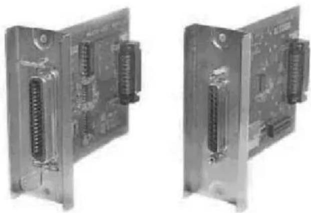
natural_image
Two identical electronic device modules with visible I/O connectors and circuit board (no text or symbols)THE RECEIVE BUFFER
The M10e printers have the ability to receive a data stream from the host in one of two ways. The receive buffer may be configured to accept one print job at a time or multiple print jobs. The single job print buffer is generally used by software programs that wish to maintain control of the job print queue so that it can move a high priority job in front of ones of lesser importance. The multiple job buffer, on the other hand prints all jobs in the order they are received by the printer, and the order of printing cannot be changed.
SINGLE JOB BUFFER
The printer receives and prints one job at a time. Each job must not exceed 2.95 MB.
MULTI JOB BUFFER
The printer is able to continuously receive print jobs, compiling and printing other jobs at the same time. It acts much like a “print buffer” to maximize the performance of the host and the printer. When using the RS232C Serial interface, the Multi Job Buffer uses either the Ready/Busy with DTR (pin 20) or X-On/X-Off flow control protocols. See these sections for more details. With an empty receiving buffer, the status of DTR is “high” (or an X-On status if using X-On/X-Off), meaning the printer is ready to receive data. When the receive buffer is holding 2.0 MB of data (1 MB from being full), DTR will go “low” (or an X-Off is sent) indicating the printer can no longer receive data. This condition is called “Buffer Near Full.”
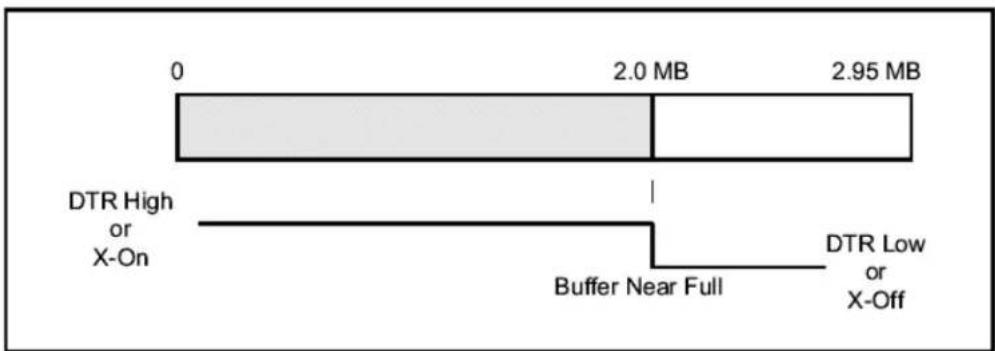
The receiving buffer will not be able to receive more data again until a “Buffer Available” condition occurs. This takes place when the receiving buffer has emptied so that only 1 MB bytes of data are being held (2.0 MB bytes from being full). At this time, DTR will go “high” or an X-On is sent to tell the host that it can again receive data.
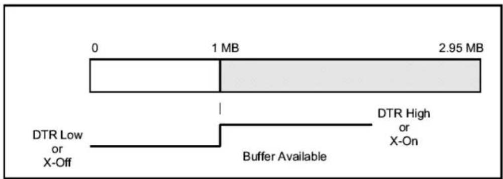
All printer error conditions (i.e., label out, ribbon out) will cause the printer to go busy (DTR "low" or X-Off) until the problem is corrected and the printer is placed on-line. The printer will also be busy if taken off-line from the front panel.
IEEE1284 PARALLEL INTERFACE
The parallel interface for the Series “e” printers is a Plug-In Interface Module that can be installed by the user. It conforms to the IEEE1284 specification. It will automatically detect the IEEE1284 signals and operate in the high speed mode. If it does not detect the IEEE1284 signals, it will operate in the standard Centronics mode, which is significantly slower. For this reason, an interface cable and host interface conforming to the IEEE1284 specification must be present to fully utilize the speed capabilities. This interface also operates bi-directionally and can report the status of the printer back to the host.
ELECTRICAL SPECIFICATIONS
Printer Connector AMP 57-40360 (DDK) or equivalent
Cable Connector AMP 57-30360 (DDK) or equivalent
Cable IEEE1284 Parallel, 10 ft. (3 m) or less
Signal Level High = +2.4V to +5.0V
Low = 0V to -0.4V
DATA STREAMS
IEEE1284 Parallel Interface Pin Assignments
| PIN | SIGNAL | DIRECTION | PIN | SIGNAL | DIRECTION |
| 1 | STROBE | To Printer | 19 | STROBE Return | Reference |
| 2 | DATA 1 | To Printer | 20 | DATA 1 Return | Reference |
| 3 | DATA 2 | To Printer | 21 | DATA 2 Return | Reference |
| 4 | DATA 3 | To Printer | 22 | DATA 3 Return | Reference |
| 5 | DATA 4 | To Printer | 23 | DATA 4 Return | Reference |
| 6 | DATA 5 | To Printer | 24 | DATA 5 Return | Reference |
| 7 | DATA 6 | To Printer | 25 | DATA 6 Return | Reference |
| 8 | DATA 7 | To Printer | 26 | DATA 7 Return | Reference |
| 9 | DATA 8 | To Printer | 27 | DATA 8 Return | Reference |
| 10 | ACK | To Host | 28 | ACK Return | Reference |
| 11 | BUSY | To Host | 29 | BUSY Return | Reference |
| 12 | PTR ERROR | To Host | 30 | PE Return | Reference |
| 13 | SELECT | To Host | 31 | INIT | From Host |
| 14 | ^(1) | To Host | 32 | FAULT | To Host |
| 15 | Not Used | 33 | Not Used | ||
| 16 | Logic Gnd | 34 | Not Used | ||
| 17 | FG | Frame Ground | 35 | Not Used | |
| 18 | +5V (Z=24K ohm) | To Host | 36 | SELECTIN^(1) | From Host |
(1) Signals required for IEEE1284 mode.
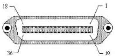
RS232 SERIAL INTERFACE
The High Speed Serial Interface is a Plug-In Interface Module that can be installed in the printer by the user.
GENERAL SPECIFICATIONS
Asynchronous ASCII Half-duplex communication
Ready/Busy Hardware Flow Control
Pin 20, DTR Control
Pin 4, RTS Error Condition
X-On/X-Off Software Flow Control
Bi-Directional Communication
Data Transmission Rate 9600, 19200, 38400, 57600 bps
Character Format 1 Start Bit (fixed)
7 or 8 data bits (selectable)
Odd, Even or No Parity (selectable)
1 or 2 Stop bits (selectable)
ELECTRICAL SPECIFICATIONS
Connector DB-25S (Female)
Cable DB-25P (Male), 50 ft. maximum length.
For cable configuration, refer to Cable
Requirements appropriate to the RS232C
protocol chosen.
Signal Levels High = +5V to +12V
Low = -5V to -12V
PIN ASSIGNMENTS
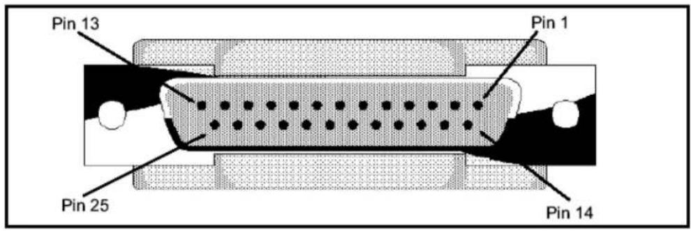
RS232C Interface Signals
| PIN | DIRECTION | SIGNAL DEFINITION |
| 1 | Reference | FG (Frame Ground) |
| 2 | To Host | TD (Transmit Data) - Data from the printer to the host computer. Sends X-On/X-Off characters or status data (Bi-Directional protocols). |
| 3 | To Printer | RD (Receive Data) - Data to the printer from the host computer. |
| 4 | To Host | RTS (Request to Send) - Used with Ready/Busy flow control to indicate an error condition. RTS is high and remains high unless the print head is open (in this case, RTS would return to the high state after the print head is closed and the printer is placed back on-line) or an error condition occurs during printing (e.g., ribbon out, label out). |
| 5 | To Printer | CTS (Clear to Send) - When this line is high, the printer assumes that data is ready to be transmitted. The printer will not receive data when this line is low. If this line is not being used, it should be tied high (to pin 4). |
| 6 | To Printer | DSR (Data Set Ready) - When this line is high, the printer will be ready to receive data. This line must be high before data is transmitted. If this line is not being used, it should be tied high (to pin 20). |
| 7 | Reference | SG (Signal Ground) |
| 20 | To Host | DTR (Data Terminal Ready) - This signal applies to Ready/Busy flow control. The printer is ready to receive data when this pin is high. It goes low when the printer is off-line, either manually or due to an error condition, and while printing in the Single Job Buffer mode. It will also go low when the data in the buffer reaches the Buffer Near Full level. |
CABLE REQUIREMENTS
| DB9 | DB25 | HOST | INTERCONNECTION | DB25 | PRINTER | |
| 1 | 1 | FG | 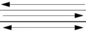 | 1 | FG | (Frame Ground) |
| 2 | 3 | RD | 2 | TD | (Transmit Data) | |
| 3 | 2 | TD | 3 | RD | (Receive Data) | |
| 8 | 5 | CTS |  | 4 | RTS | (Request to Send) |
| 7 | 4 | RTS | 5 | CTS | (Clear to Send) | |
| 4 | 20 | DTR | 6 | DSR | (Data Set Ready) | |
| 6 | 6 | DSR* | 20 | DTR | (Data Terminal Ready) | |
| 5 | 7 | SG | 7 | SG | '(Signal Ground) | |
* This connection at the host side of the interface would depend upon the pin that is being used as the Ready/Busy signal by the driving software. Typically, on a PC, it would be either CTS (pin 5) or DSR (pin 6) on a DB-25 connector.
READY/BUSY FLOW CONTROL
Ready/Busy is the hardware flow control method for the serial interface on the M10e printers. By raising/lowering the voltage level on Pin 20 of the RS232C port, the printer notifies the host when it is ready to receive data. Pin 4 (RTS) and pin 20 (DTR) are the important signals on the printer for this method of flow control. The host must be capable of supporting this flow control method for it to function properly.
X-ON/X-OFF FLOW CONTROL
X-On/X-Off flow control is used whenever hardware (Ready/Busy) flow control is not available or desirable. Instead of a voltage going high/low at pin 20, control characters representing iPrinter Ready ^1 (X-On = 11 hexadecimal) or “Printer Busy” (X-Off = 13 hexadecimal) are transmitted by the printer on pin 2 (Transmit Data) to the host. In order for this method of flow control to function correctly, the host must be capable of supporting it. X-On/X-Off operates in a manner similar to the function of pin 20 (DTR) as previously explained. When the printer is first powered on it sends an X-Off when the “Buffer Near Full” level is reached and a X-On when the data level of the buffer drops below the “Buffer Available” mark. When the printer is taken off-line manually, it transmits an X-Off indicating it cannot accept data. When it is placed back on line manually, it sends an X-On, indicating it is again available for receipt of data. If an error occurs during printing (paper out, ribbon out), the printer sends an X-Off as soon as an error condition is detected. When the error is cleared and the printer is placed back on-line, it transmits an X-On indicating it is again ready to accept data. Upon power up if no error conditions are present, the printer will continually send X-On characters at five millisecond intervals until it receives a transmission from the host.
DATA STREAMS
The data streams for X-On/X-Off and Ready/Busy flow control are constructed in the same way as they are for Ready/Busy flow control.
Section 6. Troubleshooting
Example:
NOTE: All characters are in ASCII.
UNIVERSAL SERIAL BUS (USB) INTERFACE
The Universal Serial Bus (USB) interface is a Plug-In Interface Module that can be installed by the user. It requires a driver (shipped with each printer that has the interface installed) that must be loaded on your PC and the PC must be configured to support USB peripherals using Windows 98 or above. Details for loading the USB driver are contained in the USB Interface Manual that is shipped with each printer with a USB Optional interface installed. Up to 127 devices may be connected to a USB port using powered hubs.
GENERAL SPECIFICATIONS
Connector: USB Type B Plug
Cable: 10 ft (3 m) max
Host: Windows 98 or above with USB Port
ELECTRICAL SPECIFICATIONS
Power Supply: BUS Power through cable
Power Consumption: +5V@80ma
LOCAL AREA NETWORK (LAN) OPTIONAL INTERFACE
A Local Area Network (LAN) interface is a Plug-In Interface Module that can be installed by the user. It requires a driver shipped with each printer that has the interface installed. The driver that must be loaded on your PC and the PC must be configured to run one of the supported network protocols using a 10/100BaseT LAN connection. Details for loading the LAN driver are contained in the LAN Interface Manual that is shipped with each printer with a LAN Optional interface installed.
GENERAL SPECIFICATIONS
Cable: 10/100BaseT Category 5
Connector: RJ-45 Receptical
ELECTRICAL SPECIFICATIONS
Power Supply: Powered from printer
BI-DIRECTIONAL COMMUNICATIONS
This is a two-way communications protocol between the host computer and the printer, thus enabling the host to check printer status. When Bi-Com 4 communications is selected, there is no busy signal from the printer. The host must request the complete status from the printer, including ready/busy. The host may request status in two different ways.
ENQUIRE/ACK/NAK
In the Bi-Com 4 mode, the host transmits an ENQ (05 hexadecimal) to the printer and the printer will respond with its status within five milliseconds. If printing, it will respond upon finishing the current label, then resume printing. In order for this protocol to work properly with an RS232C Optional Interface, pin 6 (DTR) and pin 5 (CTS) must be held high by the host. One way to ensure these pins are always in the correct state is to tie pin 20 (DTR) to pin 6 (DSR) and pin 4 (RTS) to pin 5 (CTS) at the printer end of the cable.
ENQUIRE (ENQ)
Upon receipt of an ENQ command, the printer responds with 25 bytes of status information bounded by an STX/ETX pair. The Bi-Com protocol works only in the Multi Job Buffer mode. The status information is defined as follows:
ID - This is a two byte number identifying the current print job ID. The print job ID is defined using the
Status - A single byte defining the current status of the printer (see the Status Byte Definition table).
Label Remaining - Six bytes defining the number of labels remaining in the current print job. The range is from 000000 to 999999 labels.
Job Name - 16 bytes of ASCII characters identifying the name assigned to the job by the
If an ENQ is received after the print job specified in the ID bytes has been completed, or there is no data in the buffer, the printer will respond with two “space” characters (20 hexadecimal) for the ID number, six “zero” characters (30 hexadecimal) in the Remaining Labels bytes and the 16 byte Job Name.
CANCEL (CAN)
If a CAN (18 hexadecimal) command is received, it will stop the print job and clear all data from the receive and print buffers. A delay of five milliseconds or more is required before any new data can be downloaded. The CAN command is effective immediately upon receipt, even if the printer is off-line or in an error condition. The printer will return an ACK (06 hexadecimal) if there is no printer error condition and a NAK (15 hexadecimal) if an error condition exists.
PRINT JOB
Upon receipt of a valid print job (
PRINT STOP (DLE)
If a DLE (10 hexadecimal) is received by the printer, the print process is stopped and an ACK (06 hexadecimal) is returned if there are no errors and a NAK (16 hexadecimal) if a printer error exists.
PRINT START (DC1)
If the printer has been stopped by receipt of a DLE (10 hexadecimal) command, it can be restarted by sending a DC1 (hexadecimal 11) command. Upon receipt of this command an ACK (06 hexadecimal) is returned if there are no errors and a NAK (16 hexadecimal) if a printer error exists.
Note: To provide compatibility with older SATO printers, the RS232C interface can be configured to use an earlier Bi-Com 3 ENQ/ACK/NAK protocol selected via DSW2-8 and DSW1-7/8 (on the RS232 Interface module). The earlier protocol did not have provisions for the Job Name and did not respond to the DLE or DCI commands. Also, there are additional Response Codes in the Status Byte Definition. It is recommended that you use the current protocol rather than the earlier version unless it is necessary for compatibility with existing software.
SECTION 7. LABEL SHEET COMMANDS
The wide carriage M10e makes it an ideal replacement for sheet fed printers. Thses commands facilitate the printing lf sheets of small labels.
Label Size
COMMAND STRUCTURE
aaaa = Height of label in dots (480-3600)
bbbb = Label width in dots (480-1600
cc = Gap between labels in dots (00-99)
dd = Number of label rows printed before cut.
Example:
Placement: Following the
Default: aaaa = 480, bbbb=480, cc=0, dd=1
COMMAND FUNCTION
To specify the size of multiple up labels
PRINTER INPUT
2
PRINTER OUTPUT
The example specifies a label size of 600 dots printed on 1020 dot wide media with not gap between label columns and cut every two rows.
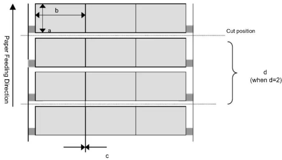
Special Notes
-
An error will occur when the Label Size specified differs from the A1 Media Size command; the format specification
_N command and the _D Variable Data command will be ignored. -
The number of multiple-up labels in a row is automatically calculated from the width specified in the
A1 command and the "bbbb" label size specified.
Label Start
COMMAND STRUCTURE
Example:
Placement: Following the
Default: None
COMMAND FUNCTION To indicate the start of a small label print specification.
PRINTER INPUT
<ESC>A106363060<ESC>PD,600,1020,0,0
<ESC>_F
<ESC>V100<ESC>H200<ESC>L0101<ESC>XMHEADER LABEL
<ESC>_<ESC>Q,1
<ESC>_F
<ESC>V100<ESC>H200<L>L0202<XM>XMABCD
<V>V200<H>H200<ESC>L0202<ESC>B103200*11111*
<ESC>_<ESC>Q,6
<ESC>_F
<ESC>V100<ESC>H200<ESC>L0101<ESC>XMFOOTER LABEL
<ESC>_<ESC>Q,1
<ESC>Z
PRINTER OUTPUT
The printer will print the label data following the command.
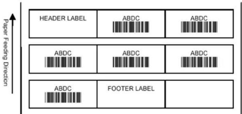
- If sequential numbering is specified after start of small label specification, sequential number on every small label is printable.
- You must specify the print number of small label with the small label quantity specification
_Q. - Do not specify the register command after the small label start specification
_F as the printing shall not operate properly as specified.
Label Format
COMMAND STRUCTURE
aa = Field number, 01-99
bb = Row Count, 01-99
Example:
Placement: Following the
Default: aa=01, bb=01
COMMAND FUNCTION To specify the layout of a small label.
PRINTER INPUT
<ESC>A106363060<ESC>PD,600,1020,0,0
<ESC>_F
<ESC>_N,01,04<ESC>V100<ESC>H200<ESC>L0202<ESC>XMABCD
<ESC>_N,02,07<ESC>V200<ESC>H200<ESC>L0202<ESC>B103200*11111*
<ESC>_N,03,02<ESC>V100<H>H400<ESC>L0202<ESC>XM22
<ESC>_D,01,AAAA<ESC>_D,02,*22222*<ESC>_D,03,22<ESC>_Q,1
<ESC>_D,01,BBBB<ESC>_D,02,*33333*<ESC>_D,03,33<ESC>_Q,2
<ESC>_D,01,CCCC<ESC>_D,02,*44444*<ESC>_D,03,44<ESC>_Q,4
<ESC>Z
PRINTER OUTPUT
The printer will print 1 label defines by the first
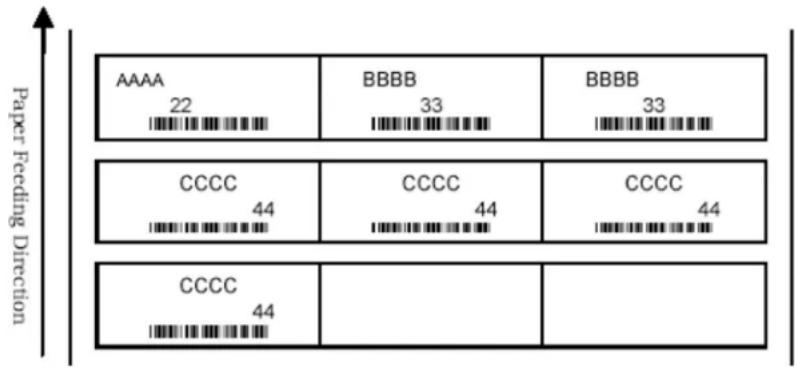
other
| Paper Feeding Direction | AAAA | BBBBB | BBBBB | |---|---|---|---| | Top Row | 22 | 33 | 33 | | Middle Row | 44 | 44 | 44 | | Bottom Row | 44 | | |Special Notes
- The selectable range for format setting
_N is limited to characters and linear bar codes. - Specify number of small labels to be printed in the
_Q Small Label Print quantity command. - Do not specify the register command after the Label Start command
_F as the printing shall not operate properly.
Label Variable Data
COMMAND STRUCTURE
aa = Field number, 01-99
n....nn = Variable data, number of characters defined in the
Example:
Placement: Following the
Default: aa = 01
COMMAND FUNCTION
To specify variable data to be placed in fields defined by
PRINTER INPUT A
PRINTER OUTPUT
7 labels will be printed, 1 data specified according to the first
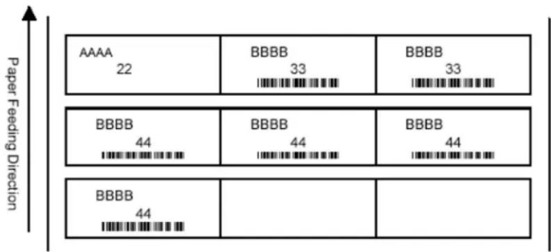
bar_stacked
| Paper Feeding Direction | AAAA | BBBB | BBBBB | |---|---|---|---| | Top Row | 22 | 33 | 33 | | Middle Row | 44 | 44 | 44 | | Bottom Row | 44 | 0 | 0 |Special Notes
-
- When the Variable Data command
_D is omitted, the default text specified by the _N command will be printed.
- When the Variable Data command
- However, when the variable data specified matches that specified by the command, the content is continued and will be printed.
Label Print Quantity
COMMAND STRUCTURE
aaaa = Number of labels to be printed, 0001-9999
b = Number of blank labels following the number of labels to be printed (may be omitted) 1-9
Example:
Placement: Following the data specified in the
Default: aaaa=0001, b=0
COMMAND FUNCTION
PRINTER INPUT
PRINTER OUTPUT To specify the number of labels to be printed.
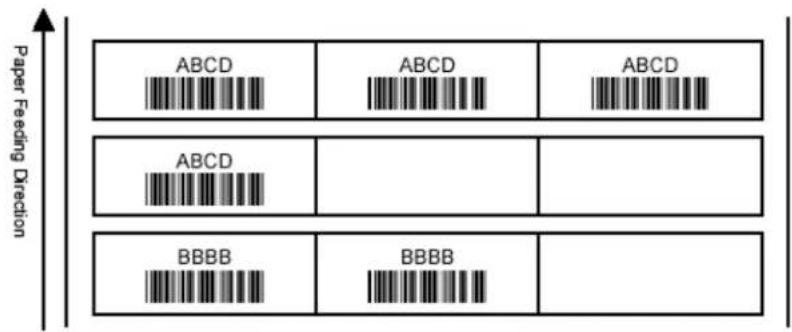
Special Notes
- The value "b" may be omitted.
SECTION 8. OPTIONAL ACCESSORIES
This section contains instructions for using the following features:
• PCMCIA Memory Cards
- Cutter
PCMCIA MEMORY CARDS
DESCRIPTION
The Memory Card Option provides the connectors and interface board for one PCMCIA memory cards slots. The printer memory can be expanded up to 16MB.
Type SRAM or Flash-ROM
Applicable Specifications PCMCIA Version 2.1 (JEIDA Version 4.1)
Size Up to 4 MB SRAM or 16MB Flash ROM
Connector Pins 68
Battery Two years for SRAM type (approximately)
Write Protect Yes
Low Battery Detect Yes (SRAM only)
INSTALLATION
Instructions for installing the Memory Card Option are included with the installation kit.
ERROR HANDLING
Memory Card error conditions are indicated to the operator using a combination of the ERROR LED on the front panel and the audible indicator.
| ERROR DESCRIPTION INDICATION REMEDY | ||
| Low Battery - Low battery condition is detected when printer is powered on. | ERROR LED: BlinkingAudible Beep: 1 longDisplay: Card LowBattery | Depress LINE key to print Card Status.Replace Memory Card battery. Note that all data will be lost when the battery is removed. |
| Card R/W Error1 No card is inserted.2 Card is write protected.3 Invalid store/recall number.4 Card has not been initialized. | ERROR LED: OnAudible Beep: 1 longDisplay: Card R/W ErrorPrinter must be powered off to reset. | 1 Insert card into selected slot.2 Remove write protect tab.3 Correct program4 Initialize card with BJF command. |
| Warning1 Duplicate number.2 Data not in print area.3 Data overflows card memory. | Audible Beep: 1 shortDisplay: NonePrinter will ignore invalid commands. | 1 Correct program.2 Correct program.3 Use card with more capacity. |
PLUG-IN INTERFACE MODULES
The Series “e” printers have user changable Plug-In Interface Modules. The Interface Module is accessible from the Rear Panel and is retained by two screws. Use the following procedure to replace an interface module.
- Turn power off both the printer and the host and remove the power and interface cables.
WARNING: Never connect or disconnect interface cables (or use a switch box) with power applied to either the host or the printer. This may cause damage to the interface circuitry and is not covered by warranty.
- Remove the two Interface Module Retaining Screws.
- Grasp the Interface Module and pull it out of the connector.
- Place the new Interface Module in the slot and press inward firmly until it is properly seated.
- Replace the two Interface Card Retaining Screws.
- If the new Interface Module is for a serial interface, set DSW1 for the proper operation.
- Connect the interface cable to the connector
CUTTER
To be added
Section 8. Optional Accessories
This page left intentionally blank.
- OPERATOR MANUAL
- TABLE OF CONTENTS
- Section 1. Printer Overview
- Section 2. Installation
- Section 3. CONFIGURATION
- Section 4. CLEANING AND MAINTENANCE
- Section 5. Troubleshooting
- Section 6. Interface Specifications
- Section 7. Label Sheet Commands
- Section 8. Optional Accessories
- INTRODUCTION
- INSTALLATION
- CONSUMABLES
- DIMENSIONS
- Ribbon Loading (not applicable for the M10eDT)
- Loading the Label Stock
- LABEL SENSING
- DIP SWITCH PANEL
- PRINTER DIP SWITCH CONFIGURATION
- DIP SWITCH PANELS
- RS232 TRANSMIT/RECEIVE SETTING
- PRINTER SET UP
- SWITCH SELECTIONS
- SOFTWARE DEFAULT SETTINGS
- PITCH
- BACKFEED OFFSET
- DISPLAY
- NORMAL MODE
- OFFLINE 000000
- PRINT DARKNESS 1 2 3 4
- PRINT SPEED 3 4 5
- PITCH OFFSET + 00mm
- CANCEL PRINT JOB YES NO
- CANCEL PRINT JOB COMPLETED
- ADVANCED MODE
- CALENDAR 00/00/00 00:00
- IGNORE CR/LF YES NO
- CHARACTER PITCH PROP FIXED
- ADVANCED MODE To ex
- CARD MODE
- V 05.00.03.00 INITIALIZING
- ADVANCED MODE The
- CARD MODE The Card
- MEM SELECT (CC1) CARD MEMORY
- CARD->MEMORYCOPY TRUETYPEFONT Y/N
- COPY START YES NO
- TRUETYPEFONTCOPY COPYING
- TRUETYPE FONTCOPY COMPLETED
- CARD COPY/FORMAT XXXXXXXX ERROR
- CARD->MEMORYCOPY SATOFONT Y/N
- SATO FONT COPY COPYING
- SATO FONT COPY COMPLETED
- MEMORY->CARDCOPY ALL <0MB> Y/N
- SERVICE MODE
- REPRINT W/FEED YES NO
- FORWARD/BACKFEED DISTANCE DEFAULT
- FORWARD/BACKFEED DISTANCE XXXmm
- EXT PIN 9 SELECT MODE1 MODE2
- EURO CODE D5
- COUNTERS MODE
- TEST PRINT MODE
- TEST PRINT MODE CONFIGURATION
- TEST PRINT SIZE 10 CM
- PRESS FEED KEY TO STOP PRINTING
- DEFAULT SETTING MODE
- DEFAULT SETTING YES NO
- DEFAULT SETTING COMPLETED
- CLEAR NON-STANDARD PROTOCOL
- ALT.PROTOCOL DEFAULT COMPLETE
- DOWNLOAD USER DEFINED PROTOCOL CODES
- USER DOWNLOAD PRESS THE LINE KEY
- USER DOWNLOAD WAITING
- HEX DUMP MODE
- ADJUSTING THE PRINT QUALITY
- PRINT (DARKNESS)
- PRINT SPEED
- CLEANING THE PRINT HEAD, PLATEN AND ROLLERS
- Supplies needed: SATO SA070 Cleaning Kit
- Cleaning the Print Head
- Cleaning the Platen and Rollers
- CLEANING THE LABEL EDGE AND PAPER END SENSORS
- Supplies needed: Flat Blade Screwdriver (Note: Some units may require a No. 2 Phillips screwdriver)
- INITIAL CHECKLIST
- USING THE IEEE1284 PARALLEL INTERFACE
- USING THE RS232C SERIAL INTERFACE
- USING THE UNIVERSAL SERIAL BUS (USB) INTERFACE
- USING THE LAN ETHERNET INTERFACE
- Printer Does Not Come Up Ready
- Installation Problems (Printer Comes up Ready but You Cannot Print)
- Checking the Interface between the Print Server and the Printer
- Checking the Network Connection and Cabling
- Intermittent Problems
- ERROR SIGNALS
- INTERFACE TYPES
- Section 6. Troubleshooting
- THE RECEIVE BUFFER
- SINGLE JOB BUFFER
- MULTI JOB BUFFER
- IEEE1284 PARALLEL INTERFACE
- ELECTRICAL SPECIFICATIONS
- DATA STREAMS
- RS232 SERIAL INTERFACE
- GENERAL SPECIFICATIONS
- PIN ASSIGNMENTS
- CABLE REQUIREMENTS
- READY/BUSY FLOW CONTROL
- X-ON/X-OFF FLOW CONTROL
- UNIVERSAL SERIAL BUS (USB) INTERFACE
- LOCAL AREA NETWORK (LAN) OPTIONAL INTERFACE
- BI-DIRECTIONAL COMMUNICATIONS
- ENQUIRE/ACK/NAK
- ENQUIRE (ENQ)
- CANCEL (CAN)
- PRINT JOB
- PRINT STOP (DLE)
- PRINT START (DC1)
- Label Size
- Label Start
- Label Format
- Label Variable Data
- COMMAND FUNCTION
- PRINTER INPUT A
- PRINTER OUTPUT
- Special Notes
- Label Print Quantity
- PCMCIA MEMORY CARDS
- DESCRIPTION
- ERROR HANDLING
- PLUG-IN INTERFACE MODULES
- CUTTER
Brand : SATO
Model : M10e
Category : Label printer