
NSC18-WN - Security Camera IC Intracom - Free user manual and instructions
Find the device manual for free NSC18-WN IC Intracom in PDF.


| Product Type | Security Camera |
| Brand | IC Intracom |
| Model | NSC18-WN |
| Resolution | 1080p Full HD (1920x1080) |
| Image Sensor | 1/2.7" Progressive Scan CMOS |
| Night Vision | IR LEDs with up to 30m range |
| Lens | 3.6mm fixed, F2.0 |
| Field of View | 90° diagonal |
| Video Compression | H.265+/H.265/H.264 |
| Power Supply | DC 12V ±10% or PoE (802.3af) |
| Power Consumption | <6W |
| Dimensions (WxHxD) | 180 x 70 x 70 mm |
| Weight | 0.5 kg |
| Weatherproof Rating | IP66 |
| Operating Temperature | -30°C to 60°C |
| Storage | MicroSD card slot, up to 128GB |
| Connectivity | Ethernet (RJ45) 10/100Mbps |
| Audio | Built-in microphone and speaker (two-way audio) |
| Motion Detection | Configurable motion detection zones |
| ONVIF Compatibility | ONVIF Profile S compliant |
| Mounting | Wall or ceiling mount with included bracket |
| Warranty | 2 years |
| Maintenance | Clean lens with soft, dry cloth; avoid harsh chemicals |
| Safety | Use only supplied power adapter or PoE switch; do not expose to rain |
| Spare Parts | Mounting kit, power adapter, screws; contact support for replacements |
| Repairability | No user-serviceable parts; refer to qualified technician |
Frequently Asked Questions - NSC18-WN IC Intracom
User questions about NSC18-WN IC Intracom
0 question about this device. Answer the ones you know or ask your own.
Ask a new question about this device
Download the instructions for your Security Camera in PDF format for free! Find your manual NSC18-WN - IC Intracom and take your electronic device back in hand. On this page are published all the documents necessary for the use of your device. NSC18-WN by IC Intracom.
USER MANUAL NSC18-WN IC Intracom

INTELLINET™
NETWORK SOLUTIONS
INT-550857-UM-0709-01
TABLE OF CONTENTS
section page
1 COMPONENTS & CONNECTIONS 6
2 SOFTWARE INSTALLATION 8
2.1 Locating the IP Address of the Camera 8
2.2 Using the Admin Utility to Locate the Camera 11
3 WEB MANAGEMENT INTERFACE 16
3.1 Logging On 16
3.2 Camera Settings 17
3.3 Pan & Tilt Settings 20
3.3.1 Preset Points 20
3.3.2 Guard Tour 21
3.4 Network Settings....23
4.4 Changing the Display Layout 54
5 TROUBLESHOOTING 57
6 SPECIFICATIONS....59
INTRODUCTION
Thank you for purchasing the INTELLINET NETWORK SOLUTIONS™ NSC18-WN Pan/Tilt Network Camera, Model 550857.
Ideal for home-network-based video streaming, this camera is simple to set up and operate, so you can soon be enjoying the benefits of these popular features:
• 1.3 Megapixel CMOS image sensor for crystal-clear images
- Motorized wide-range pan / tilt control via Web browser and utility
• Supports image resolutions up to 1280 x 1024; plus simultaneous MPEG4 and Motion-JPEG image compression
• Integrated SD/SDHC card slot for on-board storage of up to 8 GB
- Supports RTSP (Real-Time Streaming Protocol); WPS (Wi-Fi Protected Setup); WEP and WPA/WPA2 (TKIP and AES) data encryption; and UPnP (Universal Plug and Play)
- 4X digital zoom
• Programmable preset positions and patrol mode
• 2T2R MIMO technology for enhanced throughput and coverage
• Integrated e-mail, FTP, DDNS and DHCP client
• Audio support, with integrated microphone and external speaker output connector
• Integrated multi-window motion detection
- Easy-to-use 16-channel camera viewing and recording utility
- Three-Year Warranty
NOTE: Some screen images are modified to fit the format of this manual.
PACKAGE CONTENTS
• NSC18-WN Pan/Tilt Network Camera
• 2 detachable antennas
- Power adapter
• Quick installation guide
• Software CD with user manual
• Ethernet Cat5 RJ45 cable: 1.0 m (3 ft.)
NOTE: Video and audio surveillance may be forbidden by laws that vary from country to country. Check the laws where you install this device before using it for surveillance purposes.
REGULATORY STATEMENTS
EU DECLARATION OF CONFORMITY
This device complies with the essential requirements of the R&TTE Directive 1999/5/EC. This device is a 2.4 GHz wideband transmission system (transceiver) intended for use in all EU member states and EFTA countries, except in France and Italy, where restrictive use applies. In Italy, the end-user should apply for a license at the national spectrum authorities in order to obtain authorization to use the device for setting up outdoor radio links and/or for supplying public access to telecommunications and/or network services.
This device may not be used for setting up outdoor radio links in France, and in some areas the RF output power may be limited to 10 mW EIRP in the frequency range of 2454 – 2483.5 MHz. For detailed information, the end-user should contact the national spectrum authority in France.
FEDERAL COMMUNICATIONS COMMISSION INTERFERENCE STATEMENT
This equipment has been tested and found to comply with the limits for a Class B digital device, pursuant to Part 15 of the FCC Rules. These limits are designed to provide reasonable protection against harmful interference in a residential installation. This equipment generates, uses and can radiate radio frequency energy and, if not installed and used in accordance with the instructions, may cause harmful interference to radio communications. However, there is no guarantee that interference will not occur in a particular installation. If this equipment does cause harmful interference to radio or television reception, which can be determined by turning the equipment off and on, the user is encouraged to try to correct the interference by one of the following measures:
• Reorient or relocate the receiving antenna.
- Increase the separation between the equipment and receiver.
- Connect the equipment into an outlet on a circuit different from that to which the receiver is connected.
- Consult the dealer or an experienced radio/TV technician for help. This device complies with Part 15 of the FCC Rules. Operation is subject to the following two conditions: 1) This device may not cause harmful interference, and 2) This device must accept any interference received, including interference that may cause undesired operation.
FCC CAUTION
Any changes or modifications not expressly approved by the party responsible for compliance could void the user's authority to operate this equipment.
IEEE 802.11b or 802.11g operation of this product in the U.S. is firmware-limited to channels 1 through 11.
FCC RADIATION EXPOSURE STATEMENT
This equipment complies with FCC radiation exposure limits set forth for an uncontrolled environment. This equipment should be installed and operated with a minimum distance of 20 cm (approximately 8 in.) between the radiator and your body. This transmitter must not be co-located or operated in conjunction with any other antenna or transmitter.
SAFETY PRECAUTIONS
This product has been designed with safety in mind, but as electrical products can cause fires which may lead to serious damage and injury if not used properly, observe these precautions:
- Don't open the camera housing or otherwise expose yourself to dangerous voltage or other hazards inside.
- Don't attach/connect accessories that aren't designed for this device.
- Avoid operating or storing the camera in extreme temperatures (see Specifications in the user manual).
- Avoid exposing the camera to direct sunlight for a long time.
- Don't place the camera near heat sources.
- Don't place the camera near water (e.g., next to a bathtub or sink) or in an extremely hot or humid environment.
- Don't place the camera near sources of strong magnetism.
- Don't place the camera near sources of powerful electromagnetic radiation, such as radios or TV transmitters.
- Don't place the camera in locations subject to strong vibration or shock.
1 COMPONENTS & CONNECTIONS
1.1 Front and Side
Wireless Antennas — Connect the camera to the wireless network.
Focus Adjustment Ring — For manually setting the best image quality.
Built-in Microphone — For two-way audio.
Power LED — Lights after the camera completes the booting process.
Audio LED — Lights when Audio is enabled; flashes if active.
LAN LED — Lights when the LAN port is in use; flashes during data transfers.

WLAN LED — Lights when the wireless LAN port is in use; flashes during data transfers; flashes once per second when waiting for a WPS connection from an access point.
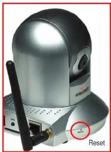
Reset — For reverting to the factory default settings. Use a straight pin, paper clip or other pointed object to press and hold this recessed button in (on the camera base's right side, as shown at right) for 5 seconds.
Tripod Ring — For securing the camera to a tripod or wall/ceiling mount. This twist ring is on the underside of the camera base.
1.2 Back / Connections
- Connect one end of the included Ethernet cable (or a similar one) to your local area network and the other end to the LAN port.
NOTE: You can skip this step if you plan to use a wireless LAN only.
-
Plug the included power adapter into an A/C outlet and connect it to the 12VDC power jack.
-
Attach the two included antennas to the connectors (shown already attached at right).
-
Press the WPS buttons on both the camera and your access point(s) to establish Wi-Fi Protected Security between the devices.
-
If desired, connect an external speaker to the 3.5mm Audio Out jack.
- As needed or desired, insert an SD (secure digital) or SDHC (high-capacity) card into the SD slot to download up to 8 GB of video files.
NOTE: Refer to Section 3.5.5 Motion Detection / SD Card Configuration and Section 3.8 SDHC.
- Position the camera in a secure location (see Safety Precautions above) and aim it as desired.

2 SOFTWARE INSTALLATION
Once the camera connections have been made, launch Internet Explorer on your computer and proceed with the instructions in the following sections.
2.1 Locating the IP Address of the Camera
The default IP address of this camera is 192.168.2.3. If you prefer to assign a different IP address to it, log on to the Web management interface of the camera first.
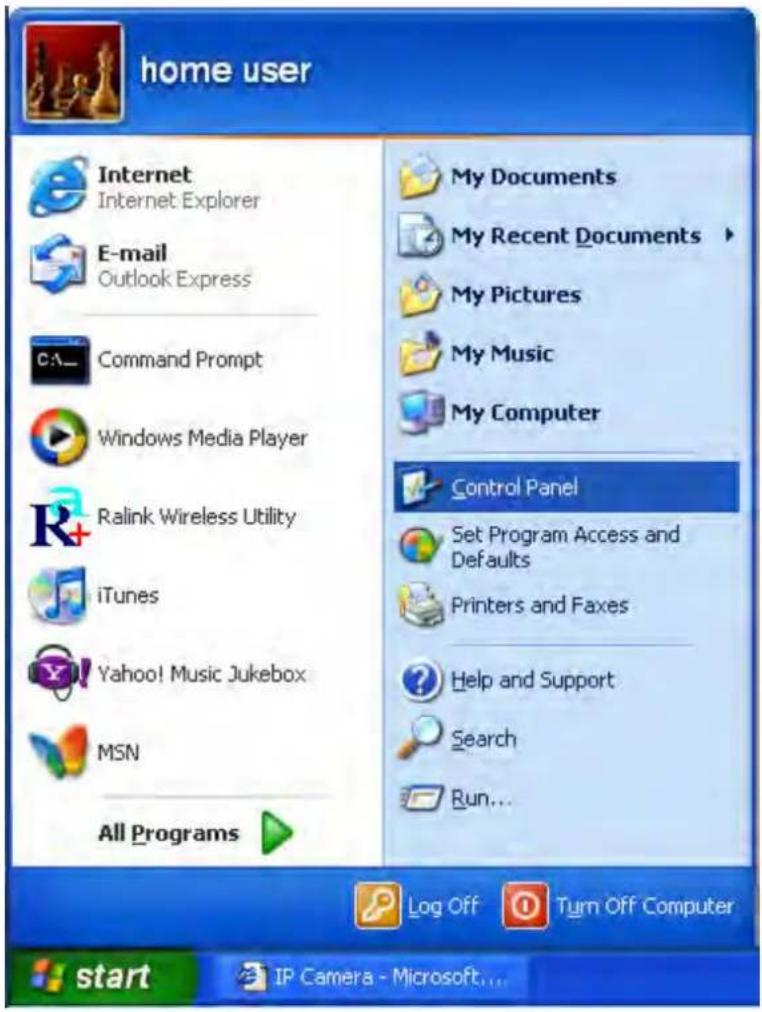
If the first three sections of the IP address of your computer aren't 192.168.2, you'll need to change the IP address of your computer. 1. From your desktop, go to Start, then Control Panel.
2. Double-click the Network Connections icon.

- Right-click on the Local Area Connection icon, then click "Properties" from the menu that displays.

- With the General menu tab/screen displayed, select "Internet Protocol (TCP/IP)," then click "Properties."
![Local Area Connection Properties General Advanced Connect using: AMD PCNET Family PCI Ethernet Ad Configure... This connection uses the following items: QoS Packet Scheduler AEGIS Protocol (IEEE 902.1x) v3.5.3.0 Internet Protocol [TCP/IP] Install... Uninstall Properties](/content/2026/05/1024084/images/9eeaad536dc88d1cbec25fcbf0aebb609284e5767a3ad6c1b690d718d375c3cd.jpg)
- In the "IP address" field on the subsequent Properties screen, enter an IP address beginning with "192.168.2" and ending with a value
between 2 and 254 (as shown). In the "Subnet mask" field, enter "255.255.255.0." Click "OK."
NOTE: If you forget the IP address of the camera after you change it, there are two ways to recover it:
- Reset back to 192.168.2.3 (and lose all settings);
- Ask your network administrator to check the DHCP release table (if the camera was set to obtain the IP address by DHCP).

2.2 Using the Admin Utility to Locate the Camera
If you can't connect to the camera using the above procedure, you can use the admin utility software to search for cameras connected to your local area network.
Insert the included software CD, and it will automatically begin to install the admin utility. NOTE: If it doesn't auto-start, go to Start on your desktop, then My Computer; double-click on the CD drive where the software CD is located, and double-click the "Setup_Admin_3.0.1" icon, as shown below.

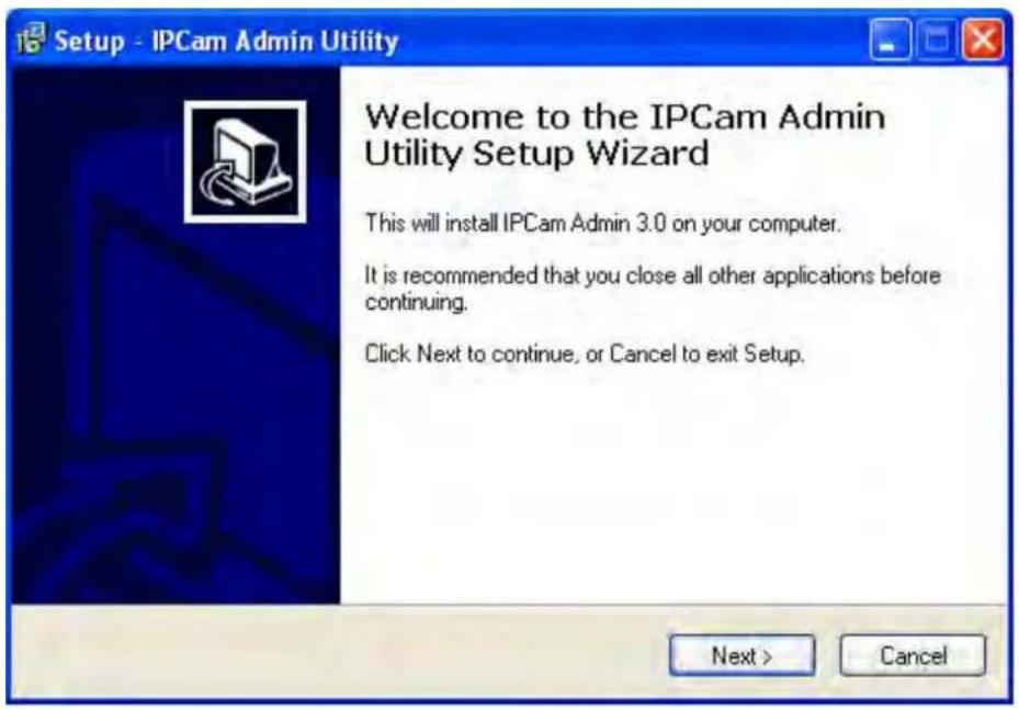
- When the Welcome to the IPCam Admin Utility Setup Wizard screen displays, click "Next."
- When the Select Destination Location screen displays, click "Next" to use the default installation folder and continue, or click "Browse" to select an existing folder or drive to install the admin utility.

- When the Select Additional Tasks screen displays, you may select the "Create a desktop icon" and "Create a Quick Launch icon" options, then click "Next" to continue.

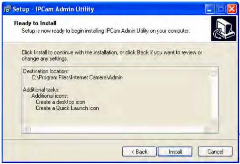
- When the Ready to Install screen displays (presenting all the selected options), click "Install" to continue or "Back" to make more changes.
- When the Completing the IPCam Admin Utility Setup Wizard screen displays, click "Finish" to complete the install. NOTE: The "Launch IPCam Admin Utility" option should be selected by default.

After the camera's admin utility is launched, all cameras found on your local area network will be displayed with basic information. To connect to a certain camera using your Web browser, double-click the camera listed.
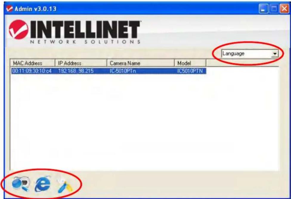
This initial screen also introduces the Language drop-down menu (above the camera-list field) and the three icons at the bottom (from left to right): Search Camera; Browse Camera via Web; and Configure Camera.
Search Camera — Click to search (and refresh the search) for all cameras on the local area network.
Browse Camera via Web — Select a camera on the list, then click to connect to the camera using your Web browser.
Configure Camera — Click to configure a camera's network and security
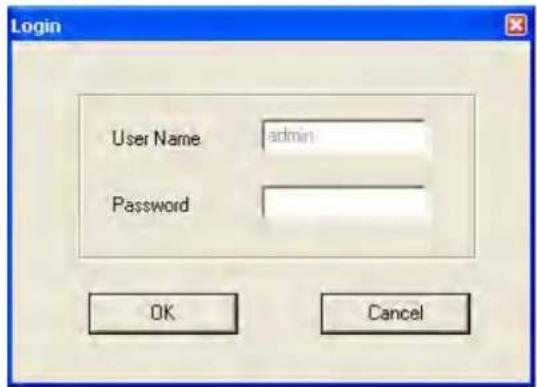
settings. When the Login screen displays, fill in the "Password" field (the default password is "1234") and click "OK" to display the LAN Setting and Security screens (both shown below). NOTE: The default username, "admin," cannot be changed here.
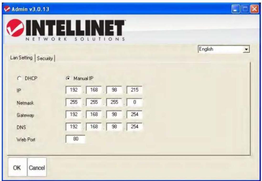
DHCP — Select to set the camera to automatically obtain an IP address from the DHCP server on the local area network.
Manual IP — Select to input the IP address information manually.
Click "OK" to save the settings.
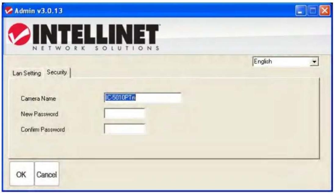
On the Security screen (above), you can change the camera's name and password (as on the Login screen, the username is always "admin" and can't be changed). Be sure you enter the same password in both the "New Password" and "Confirm Password" fields; otherwise, you'll be prompted to enter the new password again. Click "OK" to save the settings; click "Cancel" to discard changes.
3 WEB MANAGEMENT INTERFACE
3.1 Logging On
With new camera purchases, there should be no problem with the login/logon procedures. Remember, however, that if you have obtained this camera from another party after initial installation, then you'll probably need to reset the password.
-
With the camera powered on, launch your Web browser and enter the IP address of the camera in the address bar.
-
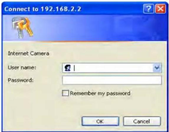
When the Internet Camera login screen displays (right), enter a username and password and click "OK." As before, the "User Name" and "Password" defaults are "admin" and "1234." NOTE: If this login screen doesn't display, go back and re-enter the IP address as necessary. Once you've logged in properly, your browser should display the
"This site might require the following ActiveX control..." message, as shown below.

- The NSC18-WN Pan/Tilt Network Camera requires a special ActiveX control (plug-in) in order to work properly. Right-click on the message in the address bar to display an

options menu (right), then click "Install ActiveX Control..." to continue. 4. When the Security Warning screen displays (below), click "Install."
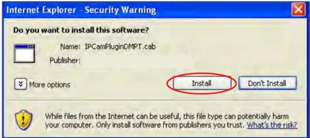
You should now be able to view live images on the Camera screen (see 3.2 Camera Settings below).
NOTE: If one or both of the messages shown here display, your computer may not have the display capability that this camera requires (refer to Section 6 Specifications) or you may not have
Microsoft DirectX installed (which you can download from Microsoft's Web site: www.microsoft.com). In some cases, your computer displays the image from the camera correctly but you still see these messages If this happens, you can just ignore them.


3.2 Camera Settings
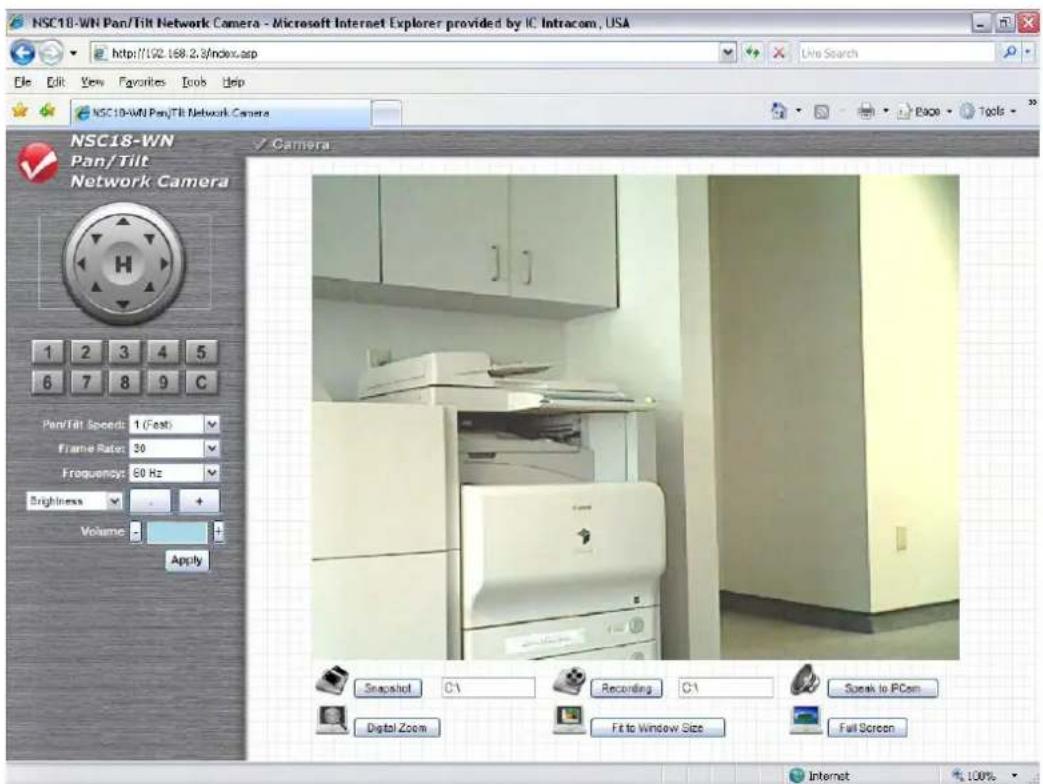
As mentioned, the first screen that displays after you log on to the Web management interface is the Camera screen (below). This is the only one of the seven options on the horizontal menu bar (just above the image area) that presents the live camera image. You can, of course, click on the Camera option from anywhere within the interface to return to the live-image display.

Pan/Tilt Speed — This specifies the moving speed when you use the Pan/Tilt function to point the camera in a different direction. Options are “1” (fastest) to “5” (slowest). The faster the speed, the less precise the control of the movement.
Resolution — Options for the video resolution are “1024 x 768,” “640 x 480” and “320 x 240” @ MPEG4; or “1280 x 1024,” “640 x 480” and “320 x 240” @ MJPG. Higher resolution provides more details in the camera image but consumes more bandwidth, which will make the image refresh very slowly. If you have a slow Internet connection, you may want to use a lower resolution to make the image refresh faster.
NOTE: "320 x 240" may reduce the image too much on a high-res monitor. To save bandwidth and maintain high resolution, select a lower Video Quality setting (see below).
Video Quality — The five options for setting the quality of the captured image range from “Lowest” to “Highest.” As with resolution, a higher image quality will provide more detail, but cost additional bandwidth. If you just want to see if there’s anything moving within the camera’s
field of view, select a lower image quality to get a higher image refresh rate.
Video Type — Select the video encoding type: "MJPEG" or "MPEG4."
Frame Rate — The highest image refresh rate of this camera is 30 (the same as a TV). However, if you are using an Internet connection with limited bandwidth and you don't need a fast image refresh rate, you can limit the maximum refresh rate (frame rate). Options are “30,” “15,” “10,” “5” and “3.”
Frequency — If the area the camera is viewing features fluorescent lighting, the image may look like it's flickering. In this case, you can adjust this setting to the frequency of the electrical power to improve the image quality. If you don't know which setting to use, just try each one and select the one with the least flicker.
Flip Mode — If you're mounting the camera on a ceiling or wall rather than any other horizontal surface, you can use this function to rotate the displayed image.
Show Date/Time — Select “Enable” to display the current date and time of the internal clock of the camera at the upper-left corner of the image; select “Disable” to hide date/time.
Video Quality Control — To account for different viewing conditions, you can adjust the video quality by controlling the brightness, saturation and sharpness levels of the displayed image. Select one of the Video Quality options from the drop-down menu, then click “+” or “−” to increase/decrease the level.
Volume — Click “+” or “−” to increase/decrease the volume level.
Apply — Click to put any of the above changes into effect. NOTE: Any changes made with the following functions are immediate.
Pan/Tilt Control — This lets you aim the camera in different directions. Click any of the eight directional buttons to move the camera; click “H” to move the camera back to the “home” (original) position.

Preset Points — You can set up to nine preset camera viewing positions,
then just click the corresponding number to instantly move the camera to that preset point. (See 3.3.1 Pan & Tilt / Preset Points for details.)

Click "C" to automatically move the view through all preset points.
Snapshot — Click to save the displayed image as an image file. A message box will appear, showing the filename and location of the
saved image file (the default filename is the current date and time).
The default directory used to save image file is "C:\"; but you can change by clicking the text field to the right of "Snapshot" and entering a new directory.
Recording — Click to record the displaying image as a video file in AVI format. You can play back the video file using Windows Media Player. To stop recording, click "Stop Recording" (the same button). As with "Snapshot," you can change the directory used to save the file.
Full Screen — Click to display the image in full-screen mode (uses all available space to display the captured image).
Digital Zoom — Click to enlarge any portion of a captured image. Select “Enable,” then drag the slide bar left or right to adjust the zoom ratio. You can also use your mouse to drag the zoom area

(the yellow square) to reposition it as desired.
Fit to Window — Click to adjust the image size to fit the browser window.
Speaker to IP Cam — You can transmit the voice received by your computer's microphone to the camera's external speaker. Click and hold this button, then speak into the microphone. NOTE: The external speaker must be connected to the camera.
3.3 Pan & Tilt Settings
In addition to pan and tilt functions, this menu option presents a couple of handy features that allow you to configure the camera for automatic movements. Click either "Preset Points" or "Guard Tour" to configure.
3.3.1 Preset Points
The camera has nine memory slots so you can define particular camera positions as "preset points" and save them for later recall.
- Select a memory slot from the "Available Positions" drop-down menu.
- Click on the image (at the top to move up, on the left to move left, etc.) to aim the camera in that direction. You may want to set Pan/Tilt Speed to a slower setting in order to move the camera more precisely.

- When the camera is in the position you want, enter a descriptive name in the "Position Name" field and click "Set to Point n" (where "n" is the number of the memory slot) to save the position. Once it's saved, the position can be instantly recalled from the Camera menu by clicking the position number on the Preset Points panel. To delete a preset position, select its memory slot from the "Available Positions" drop-down menu and click "Remove Point n" (where "n" is the number of the memory slot you want to clear).
3.3.2 Guard Tour
You can set the camera to move among any or all of the preset points (see 3.3.1 Preset Points above), plus define the amount of time spent at each stop on the "tour"; that is, the duration of each view (like a security guard making rounds). NOTE: At least two of the nine available preset positons need to be configured before you can use this function.

Add — Click to add a new guard tour (see below for detailed steps.)
Edit — Click to modify the settings of a configured tour.
Start/Stop — Click to activate a selected guard tour; click again to stop it. Once a tour has begun, go to the Camera menu screen to view the images. NOTE: Only one tour can be active at a time.
Remove — Click to delete a selected tour from the list.
Adding a Guard Tour
Click "Add" to display the Set Up Guard Tour screen below.

Name — Enter an easily recognizable name for each configured tour so its purpose is clear.
View With Random Order — Select to view preset points randomly. Available Positions — Select preset points from the drop-down menu, then click “Add to list” to include each position on this grand tour. The screen below will display, with additional options.
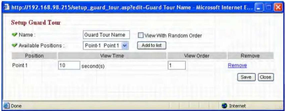
View Time — Enter the number of seconds you want the camera to stop and present the image at this position.
View Order — Assign this position a number greater than 1 and different from the other positions. Unless Random Order is selected, each tour will start “visiting” positions in order, from 1 to the highest configured number and then back to 1.
Remove — Click to delete a selected position from the list.
Save — Click to save the settings.
Close — Click to close the window and discard all changes not saved.
3.4 Network Settings
With five subsections as shown below, all network-related settings can be configured on this menu's screens. NOTE: You need to specify the TCP/IP parameters here in order to change the IP address, use PPPoE or Dynamic DNS, and activate the UPnP function.
| Network | ||||
| LAN | WLAN | Dynamic DNS | UPnP | LoginFree |
3.4.1 LAN
The IP address and port number(s) can be defined on this screen.
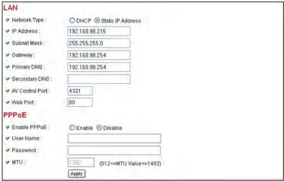
Network Type — Select “DHCP” to obtain an IP address automatically or “Static IP Address” to assign the camera a fixed IP address. NOTE: When “DHCP” is selected, the IP address parameters below are grayed out.
IP Address / Subnet Mask / Gateway — Enter the appropriate settings.
Primary DNS — Enter the IP address of the DNS server. If you don't know it, ask a network administrator or your ISP for help.
Secondary DNS — Enter the IP address of a backup DNS server, which the camera will use if the primary address is unavailable. (Optional)
AV Control Port — Enter the video transfer port number. If you have a firewall on your network, you need to allow computers on the Internet to access this port; otherwise, you won't be able to view video from the Internet.
Web Port — Enter the port number of the Web management interface.
NOTE: If it's not 80, you need to add " :port" after the camera's IP address / hostname. For example, if the HTTP port number entered here is 90 and the IP address of the camera is 10.20.20.30, then you need to input "http://10.20.20.30:90" in the address bar of Internet Explorer.
Enable PPPoE — Select “Enable” to activate the function; “Disable” to deactivate it.
User Name — Enter the PPPoE username assigned by your ISP.
Password — Enter the PPPoE password assigned by your ISP.
MTU — Enter a value for maximum transmission units (MTU) given by your ISP. NOTE: The default value should work with most ISPs (and will deliver decent network performance).
Apply — Click to put any of the above settings/changes into effect.
3.4.2 WLAN
Wireless Connection — Select “Enable” to activate the function; “Disable” to deactivate it.
Network Type — Options are “Infrastructure” and “Ad Hoc.”
- Set to “Infrastructure” when you have a wireless access point and computers with wired network connections.
- Set to “Ad Hoc” when you don’t have a wireless access point but your computer has a wireless network card. The camera will become a stand-alone wireless network point, and other wireless computers and devices can discover and connect to it without a wireless AP.

Available Networks — This is a list of all wireless access points found by the camera. Not all access points will be displayed at the same time, so if the AP you expected to connect to doesn't appear you may need to click “Refresh” several times until it does.
- Connect: Select a device you want to connect to.
- SSID: Unless a wireless AP's SSID is hidden (meaning you'll need to identify the device by its MAC address), it'll display here.
- MAC Address: If there are a lot of wireless access points in proximity (or if a wireless access point hides its SSID), you can use the MAC addresses to distinguish them.
• Signal: This indicates the radio signal strength. - Channel: This is the WAP's radio channel.
- Encryption: You need to use the same encryption type as the AP
you want to connect to. If the wireless access point does not use encryption, "Disabled" will be displayed here.
- Network Type: Displays either "Infrastructure" or "Ad Hoc."
SSID — Enter the SSID of the wireless access point you want to connect to. It should be fewer than 32 alphanumerical characters. When you select a wireless access point from the Available Networks list, its SSID will be displayed in this field automatically unless it's hidden, in which case you won't be able to connect to it.
Channel — When the network type is set to “Infrastructure,” the radio channel is auto-selected according to the channel that wireless AP uses. You can only select the channel number when the network type is set to “Ad Hoc.”
Wireless Key — Enter the encryption key of the selected wireless AP. This is required when the access point you want to connect to uses encryption.
Self PinCode — This is the WPS pin code used to connect to WPS-enabled wireless access points. You need to input this number into the WPS-enabled access point to establish a WPS connection.
Configure via Push Button — Click to put the camera in a PBC-style WPS connection state for 120 seconds. Push or click the “Start PBC” button on the wireless access point you want to connect to within 120 seconds to establish a WPS connection. (The time remaining will be displayed on the button.) NOTE: If the connection can’t be made within 120 seconds, you’ll be prompted by a message box that you can click “Start PBC” to try again.
Configure via PinCode— If you have a wireless access point's WPS PIN code, you can enter it here and click "Start PIN" to start to establish a PIN-style WPS connection.
3.4.3 Dynamic DNS
If your ISP doesn't give you a fixed Internet IP address (i.e., the Internet address you're using when you access the Internet is not always the same), this function can help you locate the IP address of the camera when you're away from home or the office.
Before you can use this function, however, you need to apply for an account at dyndns.org (http://www.dyndns.org). Detailed instructions of how to obtain a new account can be found on the dyndns.org Web site.

Enable DDNS — Select “Enable” to activate the function; “Disable” to deactivate it.
Provider — dyndns.org is currently the only option available.
Host Name — Enter a dynamic DNS hostname.
User Name — Enter a dynamic DNS username (the same used for the dyndns.org account).
Password — Enter a dynamic DNS password (the same used for the dyndns.org account).
Apply — Click to put any of the above settings/changes into effect.
3.4.4 UPnP
When this function is activated, all UPnP-compatible computers/devices on the same local network will be able to find the camera automatically. This is useful because you don't have to remember the IP address of the camera: Simply go to My Network Places (see below) and it's there!

Enable UPnP — Select “Enable” to activate the function; “Disable” to deactivate it.
Apply — Click to put any of the above settings/changes into effect.
When UPnP is activated, a popup message displays (right) Click on it to open My Network Places and you'll see the camera.


You can double-click the icon to launch Internet Explorer and directly log on to the camera's Web management interface.
3.4.5 loginfree
LoginFree is a function that allows unauthorized users to view images captured by the camera. It also lets you integrate images with your own Web applications.

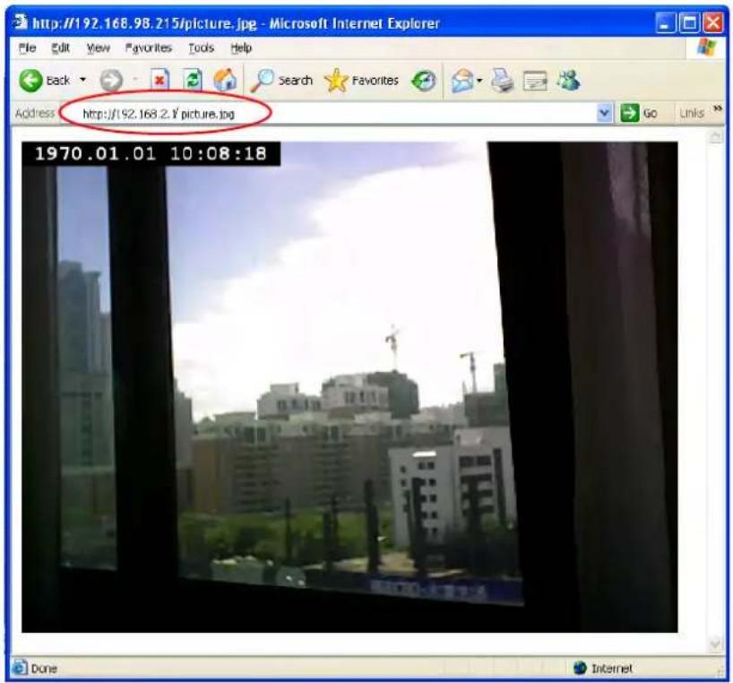
Filename — Enter a filename and click “Apply” to save the settings. Other users can now access the image by this filename with a “.jpg” extension and the camera’s IP address as the prefix. For example, if your camera’s IP address is 192.168.2.4 and the filename entered is “picture,” then anyone on the Web can access the image using the address “http://192.168.2.4/picture.jpg. NOTE: No authentication will be required to see the captured image. To disable the function, clear the text in the “Filename” field and click “Apply.”
3.5 Motion Detection Settings
This function is another useful security tool, as it takes a snapshot when there's movement in the image area being monitored. With five subsections as shown below, all motion detection-related settings can be configured on this menu's screens.
| Motion Detection | ||||
| Motion Detection | Motion Region | FTP Configuration | SD Card Configuration | |
3.5.1 Motion Detection
Enable Motion Detection — Select "Enable" to activate the function; "Disable" to deactivate it.
Motion Detection Interval — From the drop-down menu, select the time interval (in seconds) between two motions. When motion is detected, the camera won't detect any motion again during this interval. Options range from "0" (always detect new motion) to "60."
Recording Time — Select the duration (in seconds) of recorded images. Options are “1,” “2,” “3,” “4” and “5.”

Sending File Type — Select the file type that'll be saved when motion is detected. Select "JPEG" and a still picture in JPEG format will be saved; select "AVI" to save a video clip.
Send snapshot file to FTP — Select "Enable" to send the saved file to the designated FTP server when motion is detected; select "Disable" to disable the function. NOTE: You need to configure the FTP server parameters first (see 3.5.4 FTP Configuration below).
Send snapshot file to E-Mail — Select "Enable" to send the saved file to the designated e-mail address when motion is detected; select "Disable" to disable the function. NOTE: You need to configure the SMTP server parameters first (see 3.5.3 E-Mail below).
Send snapshot file to SD Card — Select “Enable” to send the saved file to an inserted SD card when motion is detected; select “Disable” to disable the function. (See 3.5.5 SD Card Configuration below.)
Apply — Click to put any of the above settings/changes into effect.
3.5.2 Motion Region
You can reduce the likelihood of a false alarm by defining the motion detection region within the image captured by the camera. By doing so, the camera will ignore motion outside the specified viewing region.
Region 1–3 — Select one, two or all three of the regions you want to configure. As each region is selected, it will appear on the currently captured image.
Sensitivity — Move the slide bar left or right to change the level of motion detection sensitivity: left to decrease sensitivity (the camera will only detect major changes in the image); right to increase sensitivity (the camera will detect minor changes in the image). The level will display as a percentage of maximum below each slide bar as it's moved to a new position.

Refresh — If the object or objects in the image captured by the camera move off screen, click to reload the image so you can re-define the motion detection region (see below).
Save — Click to save your settings.
You can re-size and re-position a region with your mouse just as you would any other image.
- Click and hold the mouse button after you mouse-over one of the eight perimeter points that define the region, then drag the mouse to re-size the region.
- Position the mouse anywhere on the region, click/hold the mouse button and drag the region to the desired position.
3.5.3 E-Mail
As mentioned in 3.5.1 Motion Detection, these settings need to be entered before you can take advantage of the “Send snapshot file to E-Mail” option.
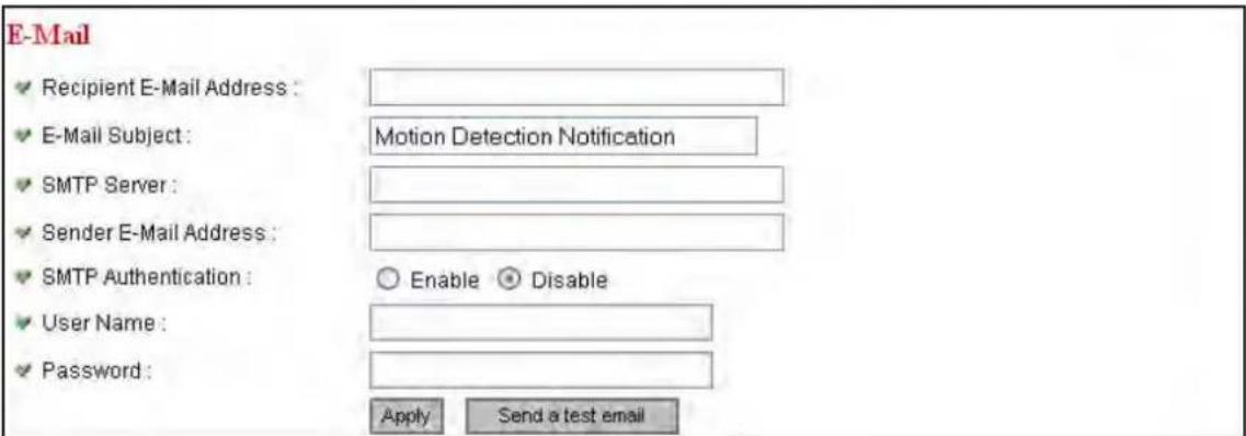
Recipient E-Mail Address — Enter the address files are to be sent to. E-Mail Subject — Enter something that will indicate the desired level of importance or urgency to the recipient.
SMTP Server — Enter the IP address or hostname of the SMTP server (the server that delivers your e-mail). If you don't know it, refer to your e-mail software (e.g., Outlook or Outlook Express) or ask your network administrator or ISP.
Sender E-Mail Address — Enter the address of the e-mail sender. This will make the e-mail more readily identifiable as to its purpose and importance. NOTE: Some servers won't forward e-mail from unknown senders, so it's highly recommended that you enter a valid address.
SMTP Authentication — Some SMTP servers require e-mail senders to be authenticated. If you're not sure whether to select "Enable" or "Disable," refer to your e-mail software (e.g., Outlook or Outlook Express) or ask your network administrator or ISP.
User Name — If your SMTP server requires authentication, enter your SMTP server username.
Password — If your SMTP server requires authentication, enter your SMTP server password.
Apply — Click to put any of the above settings/changes into effect.
Send a test e-mail — Click to confirm that your settings are valid and that the function is operating properly.
3.5.4 FTP Configuration
As mentioned in 3.5.1 Motion Detection, these settings need to be entered before you can use the "Send snapshot file to FTP" option.
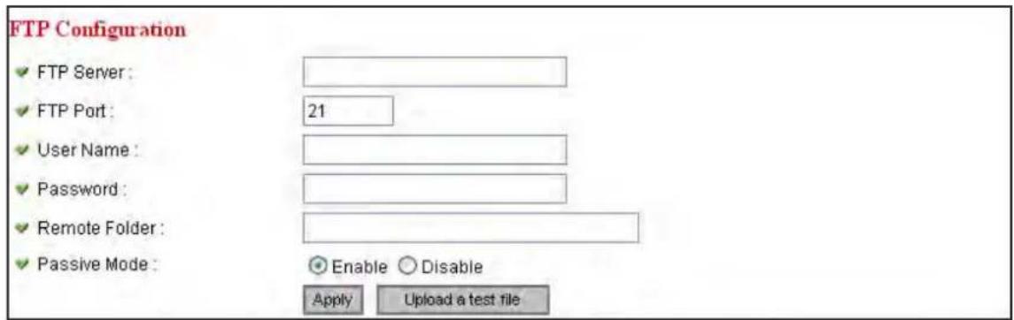
FTP Server — Enter the IP address or hostname of the FTP server.
FTP Port — Enter the port number of the FTP server.
User Name — Enter the FTP server username.
Password — Enter the FTP server password.
Remote Folder — Enter a remote folder name to be used on the FTP server. If nothing is entered, all uploaded image files will be placed in the FTP server's root directory. If necessary, ask the FTP server's administrator which folder should be used, as some names may carry restrictions that limit file placement.
Passive Mode — Select “Enable” to activate the mode; “Disable” to set to non-passive mode. Though most FTP servers work fine with either mode, some require passive mode. If you find one mode isn’t working, try the other. If you don’t know, ask the FTP server’s administrator.
Apply — Click to put any of the above settings/changes into effect.
Upload a test file — Click to confirm that your settings are valid and that the function is operating properly.
3.5.5 SD Card Configuration
Make these entries so you can find files saved on your card.
File Name Prefix — Enter what will appear before the file sequence number.
Destination Folder — Direct where to store the files.
Apply — Click to put any of the above settings/changes into effect.

3.6 System Info
With four subsections as shown below, all operations-related settings can be configured on this menu's screens.
| System Info | |||
| Camera Information | Date/Time Setting | Utilities | Status |
3.6.1 Camera Information
This screen lets you set the camera's name and administrator's password.

Camera Name — Enter an easily recognizable name for each configured camera on the network so its purpose is clear. The default name begins with “IC-” and is followed by the last six characters of the MAC address of the camera. When you change the name(s), make sure you don’t assign the same name to multiple cameras.
Password — Enter the password used when logging on to the Web management interface using “admin” as the username.
Confirm Password — Enter the password again.
Apply — Click to put any of the above settings/changes into effect.
3.6.2 Date/Time Setting
This screen gives you the option of setting the date and time of the camera's real-time clock manually or by using the network time protocol (NTP).

Set Date/Time manually — Enter the date in the first three boxes, then the time. The format for the date is YYYY/MM/DD (so that July 2, 2012 = 2012/07/02); the 24-hour format for the time is HH:MM:SS (so that 9:24:30 pm = 21:24:30).
NTP Server — Select to input the date and time automatically from the NTP server.
Time Zone — Select the appropriate time zone from the drop-down menu.
NTP Server — Enter the IP address or hostname of the NTP server. You can use the default value “pool.ntp.org” or ask your ISP for the IP address or hostname, if they have one.
Synchronize to PC time — Click to match the camera date and time to that of the computer connected to the camera.
Apply — Click to put any of the above settings/changes into effect.
3.6.3 Utilities

Upgrade Firmware — If you download the latest firmware file from www.intellinet-network.com, you can click “Browse” to select a firmware file on your computer’s hard drive and upload it to the camera later. After you select a proper firmware file from your computer, click “Upgrade Firmware” to start the upgrade. IMPORTANT: Do not disconnect or shut down during the upgrade. If the firmware file you provide is invalid or you don’t provide the firmware file properly, you’ll be prompted to select another valid firmware file and try again.
NOTE: The camera will reboot once the upgrade procedure is complete, and the IP address of the camera will reset to its default value: 192.168.2.3.
Reset to Factory Defaults — Click “Reset” to clear all settings you’ve made and revert to the original factory settings. NOTE: The camera’s IP address will reset to its 192.168.2.3 default, and you’ll need to change the computer IP address if it doesn’t begin with “192.168.2” and the subnet mask isn’t 255.255.255.0.
Reboot Device — Click "Reboot" to reboot the camera, which may help
if it responds slowly or erratically.
LED Setting — Click "Turn off LED light" if you don't want anyone in the view field of the camera to be able to tell that the camera is activated.
Click the button again to switch the LEDs back on.
3.6.4 Status
This screen provides information about the camera you may need for reference. NOTE: "Video Port" and "HTTP Port" correspond to "AV Control Port" and "Web Port," respectively, in 3.4.1 Network Settings/LAN.
| System | |
| ✓ Firmware Version : | v1.0 (Jun 2 2008 14:29:12) |
| ✓ Device Uptime : | 11 hours 25 min 58 sec |
| ✓ System Time : | 1970/01/01 19:25:58 |
| LAN | |
| ✓ IP Address : | 192.168.98.215 |
| ✓ Subnet Mask : | 255.255.255.0 |
| ✓ Gateway : | 192.168.98.254 |
| ✓ DNS Server : | 192.168.98.254 |
| ✓ MAC Address : | 00:11:09:30:10:C4 |
| ✓ Video Port : | 4322 |
| ✓ HTTP Port : | 80 |
| PPPoE | |
| ✓ Link Status : | Disconnected |
| ✓ IP Address : | |
| ✓ Subnet Mask : | |
| ✓ Gateway : | |
| ✓ DNS Server : | |
3.7 Account
If you want to allow other people to view the live image captured by the camera but don't want to allow them to modify any of the system settings, you can give them a user-level username and password (detailed below), which allows them to only view the image without being able to change any system settings.
Configure the settings for these user-level accounts on the Account screen.
Login — Enter a login username.
Password — Enter a password for this user.
Confirm password — Re-enter the password.
Add — Click to add this user account to the network.

When a user is added, it will display in the table above the "Apply" button. NOTE: However many users are enabled, only one (including the administrator) can view the camera image at a time.
Yes/No — Select to enable or disable this user account. If you just want to temporarily remove the access privilege of an account, select "No" rather than delete it, then select "Yes" to reinstate the user privileges.
Update — Click to change a username and/or password.
Delete — Click to immediately remove the account from the network.
Apply — Click to put any of the above settings/changes into effect.
3.8 SDHC
With three subsections as shown below, this screen presents options for SD-HC (secure digital – high capacity) card-related operations.
| SDHC | ||
| Status | Space Alarm | File Management |
3.8.1 Status
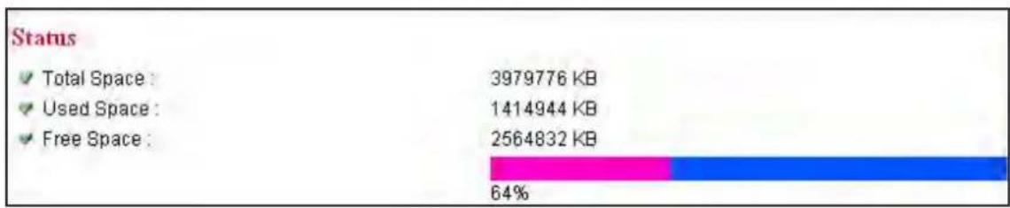
This screen displays remaining card space for storing image files.
3.8.2 Space Alarm
When you're using an SD card to store captured images and video clips, you can configure the camera to send an e-mail to you when you've reached the limit of reserved space left on the card.
![Space Alarm ✓ Recipient E-Mail Address : ✓ E-Mail Subject : [SD Card Space Alarm] ✓ SMTP Server : ✓ Sender E-Mail Address : ✓ SMTP Authentication : ○ Enable ● Disable ✓ User Name : ✓ Password : ✓ Reserved Space : 30 MB Apply Send a test email Copy Mail Config](/content/2026/05/1024084/images/009ed15368aa0afafa4e7a824e047b2c13b8d0710ea9a13fea51d49a5eece1a7.jpg)
Recipient E-Mail Address — Enter the e-mail address you want the space alarm to go to.
E-Mail Subject — Enter a subject recognizable as important.
SMTP Server — Enter the server to be used to send the e-mail.
Sender E-Mail Address — Enter the e-mail address of the sender.
SMTP Authentication — Select “Enable” if the SMTP server you’re using requires authentication, then enter the username and password below; select “Disable” if the server doesn’t require authentication. If you’re not sure, ask your ISP or network administrator.
Reserved Space — From the drop-down menu, select the amount of SD card space that will be reserved and not used.
Apply — Click to put any of the above settings/changes into effect.
Send a test e-mail — Click to send a test e-mail using this configuration. Copy Mail Config — Click if you've activated the Motion Detection function and want to use the same e-mail notification settings here.
3.8.3 File Management
This screen lets you manage the files stored on an SD card.

4 SURVEILLANCE SOFTWARE
The camera's surveillance software (the "Viewer") provides convenient functions such as video recording to complement security efforts
4.1 Installing the Surveillance Software
- Insert the included software CD, and it will automatically begin to install the surveillance software utility. NOTE: If it doesn't auto-start, go to
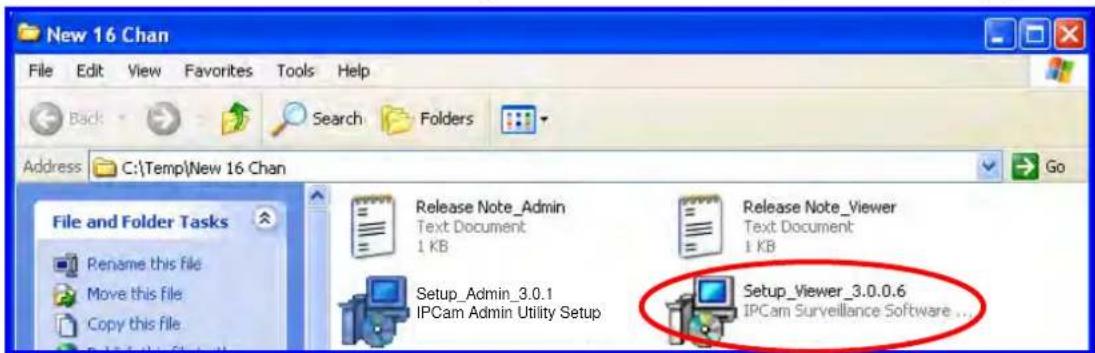
Start on your desktop, then My Computer; double-click on the CD drive where the software CD is located, and double-click the "Setup_Viewer_3.0.0.6" icon, as shown above.
- When the Welcome to the IPCam Surveillance Software Setup Wizard screen displays, note the recommendation that all other applications be closed before proceeding, then click "Next."

- When the Select Destination Location screen displays, click "Next" to continue or click "Browse" to select another folder or drive to install the surveillance software.

- When the Select Additional Tasks screen displays, select "Create a desktop icon" and/or "Create a Quick Launch icon" as desired, then click "Next."

- When the Ready to Install screen displays, showing the settings selected on previous screens, click "Install" to begin the installation procedure or "Back" to change/modify any of the settings. A status screen will display (Installing) to show the progress of the install.

- When the Completing the IPCam Surveillance Software Setup Wizard screen displays, click "Finish" and the Viewer will be activated. If you prefer to activate it later, de-select "Launch IPCam Surveillance Software" before clicking "Finish."

4.2 Viewer Controls
The Viewer can be activated by clicking its desktop/quick-launch icon or by selecting “IPCam Surveillance Software” from the Start menu’s Internet Camera folder. IMPORTANT: The Viewer software will only work with a monitor resolution setting of 1024 x 768. Be sure this is your setting before you use the Viewer; otherwise, it won’t start.
Video Display Area — The images from all connected cameras are displayed in this section.
Language — Make a selection for your operating format.
Display Layout — Click on any one of the eight camera image display layouts to implement it for the selected camera. (See 4.4 Changing the Display Layout for details.)
Full Screen (1) — Click to fill the screen with only the image from the
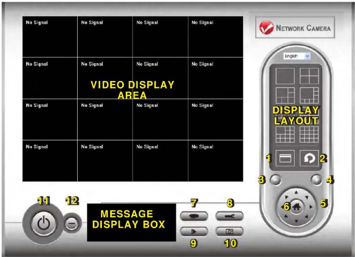
selected camera. Press
Scan (2) — Click to automatically cycle through the views from all connected cameras. Click once to activate the function (the icon turns blue); click again to stop scanning (the icon turns white). NOTE: If a camera is configured but disconnected, it will still display in a scan sequence: The view will be blank and “Disconnected” will appear in the upper-left corner of the display.
Zoom Out (3) — Click to view more of what's available in the selected camera image. NOTE: This function is available only with cameras that feature it.
Zoom In (4) — Click to view more details of the selected camera image. It may be necessary to first use the PTZ controls to identify and isolate the part of the image you want to zoom in on. NOTE: This function is available only with cameras that feature it.
PTZ Control (5) — If the connected/selected camera supports the PTZ (pan-tilt-zoom) function, you can move in eight directions by clicking on the corresponding directional arrow on the PTZ control ring.
Home (6) — Click to return the selected camera to the home (default)
position. NOTE: This function is available only with cameras that feature it.
Record (7) — Click to begin video recording from a selected camera. The start date and time of the recording is confirmed in the Message Display Box; for example, “7/2 11:23:00, Camera 4 Start Manual” (started manually). Likewise, the message “7/2 11:25:00, Camera 4 Stop Manual” would indicate the recording was manually stopped two minutes later.
Configure (8) — Click to configure the camera(s) on the network. (See 4.3 Configuration for details.)
Playback (9) — Click to display the Playback screen so you can find the previously recorded video file you want to view. Two search options are presented: Time Search presents all video files created within a specified time period; Motion Search presents all video files created by the motion detection function within a specified time period. Enter/ select "From" and "To" values in the appropriate fields, then click the corresponding "Search" button. All found videos corresponding to those parameters will be displayed as a list in the window at the right. Highlight the file you want to view and click "Play."

Snapshot (10) — Click to take a snapshot of a selected camera image. Snapshots can be saved to a storage folder on your hard drive as explained in 4.3.2.1 General (Data Directory). Only the available space on your hard drive limits the number of snapshots that can be taken. Message Display Box — Displays all system messages; for example, that a certain camera is disconnected.
Close Window (11) — Click to discontinue Viewer operation.
Minimize Window (12) — Click to minimize the Viewer window.
4.3 Configuration
Before you can effectively use the Viewer program and all its features, all cameras connected to the network need to be configured. Click the Configure button on the Viewer control screen to display the "Configure
Cameras"/"General Options" menu, and select "Configure Cameras." NOTE: If you're prompted by a Windows security alert asking you if you want to block the "IPCamViewer" program, click "Unblock"; otherwise, the Viewer program will not be able to function properly.
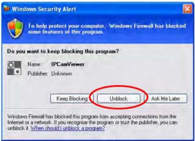
4.3.1 Configure Cameras
Clicking "Configure Cameras" on the popup menu will display the four submenus and each of their various options, as detailed below.
4.3.1.1 Camera

Channel — Select the channel number you want to set.
Camera Search — All cameras found on your local network will be displayed in this window.
Select — With a camera highlighted in the Camera Search window, click “Select” to fill in the Camera Configuration text fields in the panel above with that camera’s parameters.
Refresh — If the camera you expected to see doesn't appear in the Camera Search window (including any camera[s] connected to your network since the last scan), click to rescan and re-display.
Name* — Enter an easily recognizable name for the selected camera so you can quickly identify its location and purpose. The default entry is the first six digits of the camera's MAC address.
Model — This identifies the selected camera (and can't be changed). IP* — Enter the IP address of the selected camera.
Username — Enter the username of the selected camera.
Web Port* — Enter the Web port of the camera. The default is 80.
Password — Enter the password for the camera. The default is 1234.
Video Format — From the drop-down menu, select either MJPEG or MPEG4.
Reset — Click to clear the fields in the Camera Configuration panel.
OK — Click to save the current settings. If all entries and changes are made correctly, the selected camera's view will display on the Viewer screen (as shown at right).
Cancel — Click to cancel any changes you've made before saving.
* It's recommended that you click "Select" to fill this field.

4.3.1.2 Schedule Recording

Channel — Select the channel number you want to set.
One Time Schedules — This window displays recording schedules you set for specific cameras that will be executed only once.
New / One Time Schedules — Click to display a new One Time Schedule screen for the selected camera. Enter/select "To" and
"From" dates/times, then click "OK" to save the settings or click "Cancel" to undo any changes. NOTE: Make sure all your entries are for future times/dates; otherwise, all the settings are interpreted as invalid and the Viewer won't record the video files as expected.

Weekly Schedules — This window displays recording schedules you set for specific cameras that will run repeatedly on the day(s) selected.
New / Weekly Schedules — Click to display a new Weekly Schedule screen for the selected camera. Select applicable days of the week; enter/select a "From" time; then

set the duration of the video recording in the "Period" field (HH:MM:SS format). The end time of the recording will be calculated automatically and displayed in the "To" field. Alternatively, click "All Time Record" to record the full 24-hour period (12:00:00 AM to 11:59:59 PM) of every day. Click "OK" to save the settings; click "Cancel" to undo any changes.
Edit — For either schedule option, highlight a listing in the window and click "Edit" to modify the settings.
Delete — For either schedule option, highlight a listing in the window and click "Delete" to remove it.
OK — Click to save the current settings.
Cancel — Click to cancel any changes you've made on the Schedule Recording screen before saving.
4.3.1.3 Audio
These settings are for cameras that support audio.
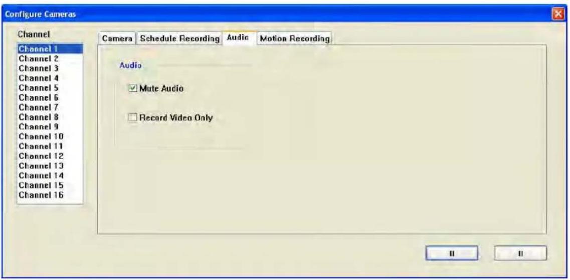
Channel — Select the channel number you want to set.
Mute Audio — Select if the designated camera does support audio but you prefer not to hear it.
Record Video Only — Select if the designated camera does support audio but you prefer not to record it along with any video recordings.
OK — Click to save the current settings.
Cancel — Click to cancel any changes you've made before saving.
4.3.1.4 Motion Record
When this feature is activated, only motions captured by the camera will be recorded, which can save significant hard disk storage space.
IMPORTANT: In situations and applications that demand a high level of security, this feature is not recommended since some nearly imperceptible motions may not be enough to trigger the camera's record function to provide information you would normally need.

Channel — Select the channel number you want to set.
Enable/Disable — Select to activate or deactivate the function.
Recording Time — Select the duration (in seconds) from the drop-down menu the camera will record after motion has been detected.
Invoke alarm when motion is triggered — Select to have an alarm sent whenever motion has been detected by the camera.
Send mail when motion is triggered — Select to have an e-mail sent whenever motion has been detected (see 4.3.2.2 E-Mail Setting).
OK — Click to save the current settings.
Cancel — Click to cancel any changes you've made before saving.
4.3.2 General Options
When you click the Configure button on the Viewer control screen and select "General Options" from the resultant popup menu (4.3 Configuration), the four submenus detailed below will display, presenting system-wide settings options for the Viewer.
4.3.2.1 General
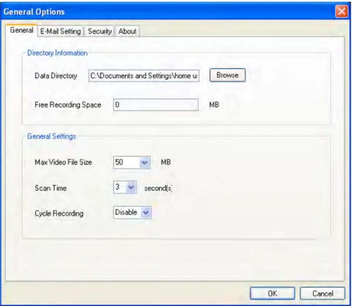
Data Directory — Enter a directory (folder) for storing video and images. To select a directory already on your hard drive, click “Browse.” Free Recording Space — Remaining storage space (MB) is displayed here. Max Video File Size — This defines the maximum file size of every video file created by the camera(s) in your network. When the size of a file exceeds this value, the Viewer will open another file to continue recording the video.
Scan Time — Enter/select an amount of time (in seconds) the Viewer will display the view from each camera when the Scan function is enabled (see 4.2 Viewer Controls).
Cycle Recording — Select an option for times when the hard disk runs out of space: "Enable" means recorded video files will be overwritten; "Disable" means they won't be.
OK — Click to save the current settings.
Cancel — Click to cancel any changes you've made before saving.
4.3.2.2 E-Mail Setting
To receive e-mail notifications of motion detection (as configured on the 4.3.1.4 Motion Record screen and including the image captured by the camera), set your e-mail parameters on this screen first.

E-Mail Subject — Enter the subject of the e-mails being sent.
Recipient E-Mail Address(es) — This window displays a list of the e-mail addresses established for notification.
New— Click to add an e-mail address for notification. Enter the address in the text field on the subsequent screen (right), then click "OK."
Edit — Highlight a listing in the Recipient E-Mail Address window, then click “Edit” to make changes

Delete — Highlight a listing in the Recipient E-Mail Address window and click "Delete" to remove it.
Sender E-Mail Address — Enter the e-mail address of the sender.
SMTP Server — Enter the IP address or host name of the SMTP server you want to use. NOTE: Most ISPs only allow users to use their SMTP server: If you're unsure which SMTP server to use, refer to your e-mail software settings or ask your Internet service provider or network administrator.
SMTP Port — Enter the port number of the SMTP server you want to use. By default, it's 25 (the setting of most SMTP servers).
SMTP Auth(entication) — If your SMTP server requires authentication, select "Enable"; if not, select "Disable." If you're unsure, refer to your e-mail software settings or ask your Internet service provider or network administrator.
SMTP Account — Enter the SMTP account (username) of your SMTP server. In most cases, it's the same as your POP3 username (used to receive e-mail). If you're unsure, refer to your e-mail software settings or ask your Internet service provider or network administrator.
SMTP Password — Enter the SMTP password of your SMTP server. In most cases, it's the same as your POP3 password (used to receive e-mail). If you're unsure, refer to your e-mail software settings or ask your Internet service provider or network administrator.
OK — Click to save the current settings.
Cancel — Click to cancel any changes you've made before saving.
4.3.2.3 Security
To prevent people from accessing this program, you can set a password to protect it. You will be required, however, to enter the password every
time you attempt to open the Viewer as long as this feature is enabled. (The Authentication Required screen at right will display: Enter the password and click “OK” to access the Viewer / surveillance software.)


Enable — Password authentication is required to access the program.
Disable — No password authentication is required to access the program.
Password — Enter the password you want to use.
Confirm Password — Enter the password you want to use again.
4.3.2.4 About
This screen simply displays the version number of the Viewer software.
4.4 Changing the Display Layout
The Viewer features eight different display layouts for up to 16 cameras, with each layout presenting a unique arrangement and number of cameras. Just click the image of the layout you want (as shown below) and the video display area will change to that layout.
Layout style1: 1 Camera only | Displays the video of 1 camera only. | |||
Layout style2: 4 Cameras | Displays the video of up to 4 cameras. | |||
Layout style3: 6 Cameras | Displays the video of up to 6 cameras.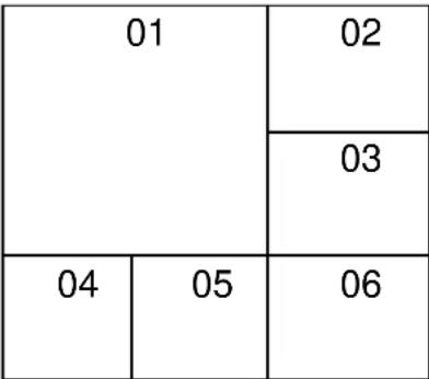 | |||
Layout style4: 8 Cameras | Displays the video of up to 8 cameras. | |||
| 01 | 02 | |||
| 03 | ||||
| 04 | ||||
| 05 | 06 | 07 | 08 | |
Layout style5: 9 Cameras | Displays the video of up to 9 cameras. | |||
| 01 | 02 | 03 | ||
| 04 | 05 | 06 | ||
| 07 | 08 | 09 | ||
Layout style6: 10Cameras | Displays the video of up to 10 cameras. | |||
| 01 | 02 | |||
| 03 | 04 | 05 | 06 | |
| 07 | 08 | 09 | 10 | |
Layout style7: 13Cameras | Displays the video of up to 13 cameras. | |||
| 01 | 02 | 03 | ||
| 04 | 05 | |||
| 06 | 07 | 08 | 09 | |
| 10 | 11 | 12 | 13 | |
Layout style8: 16Cameras | Displays the video of up to 16 cameras. | |||
| 01 | 02 | 03 | 04 | |
| 05 | 06 | 07 | 08 | |
| 09 | 10 | 11 | 12 | |
| 13 | 14 | 15 | 16 | |
5 TROUBLESHOOTING
Should the camera not function as expected, see if the problem — along with possible solutions — is listed below.
Can't connect to the camera.
- Confirm the IP address setting of the computer you're using. If it's not in the same subnet as the camera, they won't be able to communicate with each other.
- Make sure the IP address you used to connect to the IP camera is correct.
- If you forget the IP address of the camera, you need to reset it to the factory default value (192.168.2.3) by pressing the Reset button on the base of the camera. (See Section 1.1.) Then try to connect to the camera with the IP address 192.168.2.3 again.
- Make sure the camera is correctly powered (the Power LED should be on).
- If you're trying to connect to the camera from the Internet, make sure the Video/AV Control port and HTTP/Web port that the camera uses (see sections 3.4.1 and 3.6.4) are not blocked by a firewall or other software/ hardware.
- Contact your dealer for help.
The image refreshes very slowly.
- Try a higher frame rate setting, if it's not 30.
- Try a lower resolution setting.
- If you're connecting through the Internet, it could be due to a slow Internet connection, and not a problem with the camera. However, whenever the network connection is slow, you should use a lower frame rate and resolution setting.
- Adjust the antenna if you're using a wireless connection. The antenna should be perpendicular to the floor/ground to get the best reception, and the distance between the camera and the computer / wireless access point should not be too far.
- Try to adjust the MTU setting if you're using PPPoE to connect to the Internet. Ask your ISP or network administrator for details.
The camera isn't responding.
- Check the network cable or wireless connections.
- Unplug the power adapter from the wall socket and plug it in again after 10 seconds, then try to connect to the camera again.
- If the camera is correctly powered (the Power LED is on) but you still can't connect to it when you're sure the IP address is correct, contact your dealer for help.
The camera is set to send an image by e-mail or to an FTP site, but nothing is received.
- If the image is sent by e-mail, make sure it's not blocked by any anti-spam mechanism.
- Make sure you have proper permission for FTP uploading (click "Upload a test file").
- Make sure the username and/or password for the SMTP server is correct if your SMTP server requires authentication (click "Send a test email").
- Change the threshold to a more sensitive setting.
The Pan/Tilt function makes a strange sound.
- Check for (and remove) anything that could be jamming the camera or otherwise interfering with its movement.
- If the camera doesn't respond when you're trying to use the Pan/Tilt function, the servo motor inside the camera may be dead. Return the camera to your dealer and ask for help.
6 SPECIFICATIONS
Standards
- IEEE 802.11b (11 Mbps Wireless LAN)
- IEEE 802.11g (54 Mbps Wireless LAN)
- IEEE 802.11n Draft 2.0 (300 Mbps Wireless LAN)
- IEEE 802.3 (10Base-T Ethernet)
- IEEE 802.3u (100Base-TX Fast Ethernet)
General
• 32-bit ARM9 RISC CPU
• DSP: Prolific PL-1029
- 4 MByte flash memory
• 32 MByte SDRAM
- Supported image resolutions: - MPEG4: 1024 x 768, 640 x 480 and 320 x 240
- Motion=JPEG: 1280 x 1024, 640 x 480 and 320 x 240
• Video frame rate: max. 30 fps
- Audio support:
- Half duplex
- Bandwidth: GSM610 PCM, 8 kHz, 13 kbit/s
- Microphone: built-in
- Audio line out jack: 3.5 mm / 1.8"
- Protocols supported: TCP/IP, DHCP, PPPoE, ARP, ICMP, FTP, SMTP, DNS, NTP, UPnP, HTTP, TCP, UDP, RTSP
• Certifications: FCC Class B, RoHS, CE
Image Sensor and Lens
- 1/4" Micron Progressive Scan CMOS sensor
• 1.3 Megapixel resolution (1,280 H x 1,024 V)
- Manual brightness,
saturation, sharpness control
• Minimum illumination: 1 lux at F2.8
- Focal length 5.0 mm, angular field of view 53°, object distance 0.6 m to infinity
- Viewing angle 355° horizontally and 120° vertically
- Control via directional arrow buttons, mouse point-and-click (Web browser) or the 16-channel viewing/recording utility
- 9 preset positions
- Patrol mode: Presets can be : grouped together in different guard tours
Pan/Tilt Control
Network
• LAN connector: RJ45 port to connect to 10/100 Mbps Ethernet
Wireless
- Chipset: Ralink RT3052
- Wireless frequency range: 2.400 – 2.483 GHz
- Modulation technologies: - 802.11b: Direct Sequence Spread Spectrum (DSSS): DBPSK, DQPSK, CCK
- 802.11g: Orthogonal Frequency Division Multiplexing (OFDM): BPSK, QPSK, 16QAM, 64QAM
- 802.11n: Orthogonal Frequency Division Multiplexing (OFDM): BPSK, QPSK, 16QAM, 64QAM
• Data rates: -
IEEE 802.11b (11 Mbps, 5.5 Mbps, 2 Mbps, 1 Mbps)
-
IEEE 802.11g (54 Mbps, 48 Mbps, 36 Mbps, 24 Mbps, 18 Mbps, 12 Mbps, 9 Mbps, 6 Mbps)
- IEEE 802.11n (MCS0-15: up to 300 Mbps)
- Data encryption: WEP (64-bit & 128-bit), WPA- and WPA2-PSK (with TKIP and AES authentication)
- Antennas:
- 2 detachable dipole antennas with 3 dBi gain each
- 2T2R MIMO mode (2 transmitters, 2 receivers)
Power
- External power adapter: 12 V DC, 1.0 A
System Requirements
• Windows 2000, XP, Vista, Windows 7
• Computer with network connection
- Web browser support: MS Internet Explorer 6.0 or higher (ActiveX)
Package Contents
• NSC18-WN Pan/Tilt Network Camera
- 2 detachable antennas
- Power adapter
- Quick installation guide
- Software CD
- Ethernet Cat5 RJ45 cable: 1.0 m (3 ft.)

INTELLINET™
NETWORK SOLUTIONS
INTELLINET NETWORK SOLUTIONS™ offers a complete line of active and passive networking products.
Ask your local computer dealer for more information or visit
www.intellinet-network.com.

- INTELLINET™
- TABLE OF CONTENTS
- SECTION PAGE
- INTRODUCTION
- PACKAGE CONTENTS
- REGULATORY STATEMENTS
- EU DECLARATION OF CONFORMITY
- FEDERAL COMMUNICATIONS COMMISSION INTERFERENCE STATEMENT
- FCC CAUTION
- FCC RADIATION EXPOSURE STATEMENT
- SAFETY PRECAUTIONS
- 1 COMPONENTS & CONNECTIONS
- 1.1 FRONT AND SIDE
- 1.2 BACK / CONNECTIONS
- 2 SOFTWARE INSTALLATION
- 2.1 LOCATING THE IP ADDRESS OF THE CAMERA
- DOUBLE-CLICK THE NETWORK CONNECTIONS ICON
- 2.2 USING THE ADMIN UTILITY TO LOCATE THE CAMERA
- 3 WEB MANAGEMENT INTERFACE
- 3.1 LOGGING ON
- 3.2 CAMERA SETTINGS
- 3.3 PAN & TILT SETTINGS
- 3.3.1 PRESET POINTS
- 3.3.2 GUARD TOUR
- ADDING A GUARD TOUR
- 3.4 NETWORK SETTINGS
- 3.4.1 LAN
- 3.4.2 WLAN
- 3.4.3 DYNAMIC DNS
- 3.4.4 UPNP
- 3.4.5 LOGINFREE
- 3.5 MOTION DETECTION SETTINGS
- 3.5.1 MOTION DETECTION
- 3.5.2 MOTION REGION
- 3.5.3 E-MAIL
- 3.5.4 FTP CONFIGURATION
- 3.5.5 SD CARD CONFIGURATION
- 3.6 SYSTEM INFO
- 3.6.1 CAMERA INFORMATION
- 3.6.2 DATE/TIME SETTING
- 3.6.3 UTILITIES
- 3.6.4 STATUS
- 3.7 ACCOUNT
- 3.8 SDHC
- 3.8.1 STATUS
- 3.8.2 SPACE ALARM
- 3.8.3 FILE MANAGEMENT
- 4 SURVEILLANCE SOFTWARE
- 4.1 INSTALLING THE SURVEILLANCE SOFTWARE
- 4.2 VIEWER CONTROLS
- 4.3 CONFIGURATION
- 4.3.1 CONFIGURE CAMERAS
- 4.3.1.1 CAMERA
- 4.3.1.2 SCHEDULE RECORDING
- 4.3.1.3 AUDIO
- 4.3.1.4 MOTION RECORD
- 4.3.2 GENERAL OPTIONS
- 4.3.2.1 GENERAL
- 4.3.2.2 E-MAIL SETTING
- 4.3.2.3 SECURITY
- 4.3.2.4 ABOUT
- 4.4 CHANGING THE DISPLAY LAYOUT
- 5 TROUBLESHOOTING
- CAN'T CONNECT TO THE CAMERA
- THE IMAGE REFRESHES VERY SLOWLY
- THE CAMERA ISN'T RESPONDING
- THE CAMERA IS SET TO SEND AN IMAGE BY E-MAIL OR TO AN FTP SITE, BUT NOTHING IS RECEIVED
- THE PAN/TILT FUNCTION MAKES A STRANGE SOUND
- 6 SPECIFICATIONS
- STANDARDS
- GENERAL
- IMAGE SENSOR AND LENS
- PAN/TILT CONTROL
- NETWORK
- WIRELESS
- POWER
- SYSTEM REQUIREMENTS
Brand : IC Intracom
Model : NSC18-WN
Category : Security Camera