
D465ML SP - Screen HYUNDAI - Free user manual and instructions
Find the device manual for free D465ML SP HYUNDAI in PDF.


| Product Type | Digital Signage Display |
| Model | Hyundai D465ML SP |
| Display Technology | TFT LCD |
| Screen Size (Diagonal) | 46 inches (approximately) |
| Active Area (H x V) | 1018.08 x 572.67 mm |
| Native Resolution | 1920 x 1080 (Full HD) |
| Recommended Resolution | 1920 x 1080 @ 60 Hz |
| Pixel Pitch | 0.53 mm |
| Input Connectors | HDMI, PC D-SUB, Component (optional), Video (optional), PC Audio, Component Audio, Video Audio, RS232C |
| Output Connectors | HDMI, PC D-SUB, Component (optional), Video (optional), Audio L/R, RS232C |
| Power Supply | AC 100-240V, 50/60 Hz |
| Typical Power Consumption | 250 W |
| Control Type | Remote control, front panel buttons, RS232C |
| OSD Functions | Picture mode, color tone, size, PC adjustment, noise reduction, audio, time, key lock, multi-vision, heat control |
| Multi-Vision Support | Up to 25 units in series |
| Safety Compliance | FCC Class A, CE (EMC, LVD) |
| Cleaning Instructions | Use a soft dry cloth; avoid chemicals, alcohol, or solvents |
| Mounting | VESA compatible (not specified, typical 400x400 mm for 46") |
| Weight (estimated) | Approximately 18-22 kg without stand |
| Operating Temperature | 0°C to 40°C (estimated) |
Frequently Asked Questions - D465ML SP HYUNDAI
User questions about D465ML SP HYUNDAI
0 question about this device. Answer the ones you know or ask your own.
Ask a new question about this device
Download the instructions for your Screen in PDF format for free! Find your manual D465ML SP - HYUNDAI and take your electronic device back in hand. On this page are published all the documents necessary for the use of your device. D465ML SP by HYUNDAI.
USER MANUAL D465ML SP HYUNDAI
NOTE : This equipment has been tested and found to comply with the limits for a Class A digital device pursuant to Part 15 of the FCC Rules.
These limits are designed to provide reasonable protection against harmful interference in a residential installation.
This equipment generates, uses, and can radiate radio frequency energy and, if not installed and used in accordance with the instructions, may cause harmful interference to radio communications.
However, there is no guarantee that interference will not occur in a particular installation.
If this equipment does cause harmful interference to radio or television reception, which can be determined by turning the equipment off and on, the user is encouraged to try to correct the interference by one or more of the following measures:
- Reorient or relocate the receiving antenna.
- Increase the separation between the equipment and receiver.
- Connect the equipment into an outlet of a circuit different from that to which the receiver is connected.
- Consult the dealer or an experienced radio/Monitor technician for assistance.
Changes or modification not expressly approved by the party responsible for compliance could void the user's authority to operate the equipment.
Connecting of peripherals requires the use of grounded shielded signal cables.
DECLARATION OF CONFORMITY
For the following product :
All of Digital sigange HYUNDAI IT provides
Manufactured at :
(factory name, address)
-
Hyundai IT Corp. 1229 In-ri, Apo-eup Gimcheon, Gyeongsangbuk-do 740-860 Rep. of Korea
-
Hyundai IT Corp. San 136-1 Ami-ri, Bubal-eub, Ichon-si, Kyungki-Do, 467-860 Rep. of Korea
We herewith confirmed to comply with the requirements set put in the Council Directive on the Approximation of the Lows of the Member States relating to Electromagnetic Compatibility Directive (89/336/EEC), Low-Voltage Directive(73/23/EEC, 93/68/EEC). For the evaluation regarding the Directives, the following standards were applied:
EN60065 : 2002
Major features ....2
Safety Information 2
Be sure to understand ....5
Check the product list 6
Proper location for product installation ....7
Title and function of each part 8
How to Connecting Kiosk ....11
How to Connecting Digital RGB(HDMI) 12
How to Connecting analog RGB (PC D-SUB) 14
How to Connecting the component (Option) 16
How to Connecting the the video (Option) 18
Adjusting OSD and explanation of its function ....19
Diagnosis 33
Specifications 35
**REMOTE CONTROL / RS232C COMMAND SPEC
DIGITAL SIGNAGE
Major features
This product has been designed to enable the user ease of use, and display information effectively and conveniently.
- TFT LCD Module adopted
D320ML(I/G) / D400ML / D420ML(I/G/P/T) / D460ML(I/G/P/T/H) / D468ML(I/G/P/T/H) / D460SL(I) : 1366 x 768 WXGA (HD)
D405ML(I/G) / D407ML(I/G/P/T) / D425ML(I/G/P/T) / D465ML(I/G) / D467ML(I/G/P/T) / D525ML(I/G) / D825ML(I/G) / D525SL(I) / D705ML(I/G) / D705SL(I) / D825SL(I) : 1920 x 1080 WUXGA (Full HD)
• Vivid digital color display - OSD control function
• Automatic Image control
• Automatic temperature control - Analog/Digital RGB(HDMI) input and output
• Y Pb Pr/AV input and output
• Built in multi-vision function
Safety Information
This product is designed to ensure user's safety.
Avoid the following items to prevent serious electric shot and other dangers.
- Do not place wet objects on or around the product or the power cord.
- Do not cover or insert anything over or into the ventilation openings.
- Do not place in a location where damage can be caused by oil, smoke, high temperature, high humidity, dust etc.
- The product is not suitable for use at visual display workplaces according to §2 of the German Ordinance for Work with Visual Display Units.
DIGITAL SIGNAGE
- The main plug of the power supply cord shall remain readily operable.
- An apparatus with CLASS I construction shall be connected to a Mains socket outlet with a protective earthing connection.
- Make sure that the power cord and other cables are correctly plugged in.
- Plug the power cord correctly into the end, do not wobble/jiggle, it may cause electric shock fire.
- Do not touch the power cord with wet hands, it may cause electric shock.
- Overloaded AC outlets and extension cables are as dangerous as the power cord being damaged, call service engineer for replacement as it may cause electric shock or fire.
- Do not use multiple devices in a single power outlet, it may cause overheating or fire.
- Do not use or place sharp objects near the LCD surface, as this can cause damage to the screen itself.
- When cleaning the LCD screen / Surface, do not use chemical cleaning products as this can seriously damage the special coatings on the screen. Only use water to dampen a soft cloth and lightly clear the screen.
- Over time dust deposits can build up inside the product, this can cause the product to overheat thus causing premature malfunction or fire. Please do not attempt to clean the inside of the product yourself, please contact the local service agent.
- Do not use alcohol or strong chemical solvent such as methyl, ethyl or a Isopropyl.
- In the case of cleaning, be sure to remove the power cord and wipe with a soft dry fabric.
- Keep batteries for the remote control out of children's sight.
- Batteries should be inserted using the correct polarity (+,-).
- Use only new batteries, do not mix old & new.
- Place unit on a stable bracket or surface.
- More than 2 people should work together when moving or installing.
DIGITAL SIGNAGE
- Do not hang on or jump to the product or mounting rack.
- When the product is left unused for a long time, be sure to unplug the power cord.
- In the case of damage or breakage do not attempt to self repair, please contact local service engineer.
- For D460SL(I), D525SL(I), D705ML(I/G), D705SL(I), D825SL(I), install the product on the flat surface and secure the wheels not to move itself or fall down.
- For D460SL(I), D525SL(I), D705ML(I/G), D705SL(I), D825SL(I), make sure to turn the power off before connecting cables.
- This manual contains general instructions for the display products only so refer to the provided CD-ROM manual and the driver installation manual for the driver installation instructions for touch screen and/or touch screen itself.
- The apparatus shall not be exposed to dripping or splashing and that no objects filled with liquids, such as vases, shall be placed on the apparatus.
- Shall be connected to a MAINS socket outlet with a protective earthing connection.
- The disconnect device shall remain readily operable.
- The socket-outlet shall be installed near the equipment and shall be easily accessible.
- Use only with a cart, stand, tripod, bracket, or table specified by the manufacturer, or sold with the apparatus. When a cart is used, use caution when moving the cart/apparatus combination to avoid injury from tip-over.

DIGITAL SIGNAGE
Be sure to understand
Image quality of the product

CAUSE
Due to the nature of LCD's property, Afterimage can occur. Afterimage appears when identical frames / images are displayed continuously. If displayed for prolonged periods of time this can become permanent.

PREVENTION
When you display a freeze frame for a long time, lower the brightness and contrast (Brightness, 70/ Contrast, 80). Also it can be prevented by using moving frame.

COUNTERMEASURES
Temporary afterimage can be alleviated by displaying white or moving frame about 10 hours.(But, permanent afterimage cannot be disappeared according to the property of LCD) This method is used to remove temporary afterimage that may occur after displaying a still frame for a certain time. It can take several minutes or hours to remove afterimage according to the severity. In the case that your cannot avoid displaying identical still image continuously, you can prevent it by displaying moving image for 2 or 3 minutes in every hour. As the brightness of still image and time of display are the cause of afterimage, you are recommended to lower the brightness in that case.

Above problem shall not be covered by warranty.
DIGITAL SIGNAGE
Check the product list
Please check the following components provided with the product after you open the box.
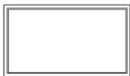
natural_image
Empty rectangular frame with gray border (no text or symbols)Base Frame Type


Remote control & batteries Power Cord
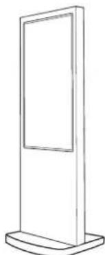
natural_image
Simple line drawing of a vertical rectangular platform with a flat top and base (no text or symbols)Kiosk Type (Portrait)

natural_image
Simple line drawing of a rectangular signpost with a flat top and base (no text or symbols)Kiosk Type (Landscape)
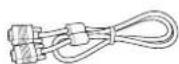
User's manual D-SUB Cable

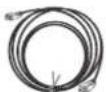
HDMI to DVI Cable (Option) HDMI cable

RS232C Cable (Option)
! please check the following components provided with the product after you open the box and contact the dealer if any missing.
** The contents may vary depending on models and sometimes the contents may be attached on the product.
Proper location for product installation
DIGITAL SIGNAGE
- Locate the product at least 30cm away from the electric appliance or heating product.
- The product must be placed at least 10cm away from the wall and ground.
- Keep the product out of direct ray of light and locate screen not to be reflected by the sunlight.
- Make sure the mounting rack firmly tightened before installation.

Please take extra care during installation, it is possible to cause damage if the unit is handled badly or knocked.
Title and function of each part
Control Panel
DIGITAL SIGNAGE
① Remote control receiving sensor.
② Power display LED red-stand by/ Green-working.
③ \~ ⑩ OSD button.
③ Power button ; to turn the power on or off.
4 Input selection button: to select other connected device.
⑤ Menu button : to display menu or exit from the menu.
6 select button.
7 To move down in OSD menu.
8 To move up in OSD menu.
9 To move left and control the volume down in OSD menu.
10 To move right and control the volume up OSD menu.

** The locations of OSD board and remote control receiving sensor may vary depending on models.
DIGITAL SIGNAGE
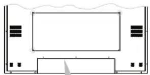
① AC IN
② AC POWER SWITCH
③ HDMI IN
4 HDMI OUT
5 SPEAKER OUT
6 PC D-SUB IN
7 PC D-SUB OUT
8 UPGRADE
9 PC AUDIO IN
10 RS-232C OUT
11 RS-232C IN
12 COMPONENT IN (Y Pb Pr)
13 COMPONENT OUT (Y Pb Pr)
14 CVBS IN
15 CVBS OUT
16 COMPONENT AUDIO IN (L R)
17 COMPOSITE AUDIO IN (L R)
natural_image
Simple line drawing of a rectangular device with internal components and a central screen (no text or symbols)
natural_image
Simple line drawing of an open door with a handle, no text or symbols present
** The locations of connectors may vary depending on models.
- The items no. 12–17 are optional items.
- When you select the "Source" button on the remote control, the "Source" menu of the "Option" item is displayed.
DIGITAL SIGNAGE
Remote control
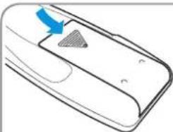
How to insert batteries

① To turn the power on or off.
② Move up in OSD menu.
③ To move left or control the volume down in OSD menu.
4 To move right or control the volume up in OSD menu.
5 To move down in OSD menu.
6 Select in OSD menu.
⑦ Display the menu screen.
8 Close the menu screen.
9 Convert the input signal.
natural_image
Line drawing of a mobile phone with a blue arrow pointing to the screen (no text or symbols)1

natural_image
Line drawing of a handheld device with a triangular button and label '2-3' (no text or symbols on the device itself)Pull while pressing at rear lid. Insert the batteries into proper polarities (+,-).

natural_image
Diagram of a car interior showing a blue arrow pointing to a textured area on the door (no text or symbols)Use after the lid closed.
DIGITAL SIGNAGE
How to Connecting Kiosk

DIGITAL SIGNAGE
How to Connecting Digital RGB(HDMI)

- Please ensure that the power to the device is switched off, then connect each cable one after another before restoring power.
① when connect HDMI to HDMI cable
② when connect DVI to HDMI cable
- must utilize device with DVI signal output from peripheral device
-
Connect the power code to the product.
-
Turn on the power of the product and peripheral device. Screen shows up within 10 seconds.
- Select "HDMI" input by pressing "SOURCE" on OSD button or remote control.
- HDMI input gives better video quality than analog RGB input.
- Both HDMI and analog RGB support plug and play.
DIGITAL SIGNAGE
Support timing for HDMI
| NO Resolution | Horizontal frequency (KHz) | Vertical frequency (Hz) | |
| 1 | 480p 640 x 480p 60 | ||
| 2 | 576p 720 x 576p 50 | ||
| 3 | 720p 1280 x 720p 50 / 60 | ||
| 4 | 1080i 1920 x 1080i 50 / 60 | ||
| 5 | 640 x 480 31.47 59.94 | ||
| 6 | 640 x 480 37.88 60.32 | ||
| 7 | 1024 x 768 48.36 60 | ||
| 8 | 1360 x 768 47.70 60 | ||
| 9 | 1360 x 768 64.00 60 | ||
| 10 | 1600 x 1200 75.00 60 | ||
| 11 | 1920 x 1080 67.50 60 | ||
| 12 | 1080p 1920 x 1080p 60 | ||

9, 10, 11 and 12 are only for Full HD
How to Connecting analog RGB (PC D-SUB)
DIGITAL SIGNAGE
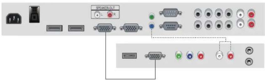
- Please ensure that the power to the device is switched off, then connect each cable one after another before restoring power.
- Connect D-SUB to D-Sub cable. Then tighten the screw of the cable after connecting PC D-SUB.
- Connect the power cord to the product.
- Turn on the power of the product and PC. The screen will appear within 10 seconds.
- Select "PC" input by pressing "SOURCE" on OSD button or remote control.
– HDMI input gives better video quality than analog RGB input. - Both HDMI and analog RGB support plug and play.
DIGITAL SIGNAGE
Support timing for PC
| NO Resolution | Horizontal frequency (KHz) | Vertical frequency (Hz) | |
| 1 | 640 x 480 31.47 59.94 | ||
| 2 | 800 x 600 37.88 60.32 | ||
| 3 | 1024 x 768 48.36 60.00 | ||
| 4 | 1360 x 768 47.71 60.00 | ||
| 5 | 1280 x 1024 64.00 60.00 | ||
| 6 | 1600 x 1200 75.00 60.00 | ||
| 7 | 1920 x 1080 67.50 60.00 | ||
!
5, 6 and 7 are only for Full HD
How to Connecting the component (Option)
DIGITAL SIGNAGE

- Please ensure that the power to the device is switched off, then connect each cable one after another before restoring power.
- Connect the component cables to Y Pb, and Pr correctly. Connect BNC cable and tighten.
- Connect the power cord to the product.
- Turn on the power of the product and peripheral device. The screen will appear within 10 seconds.
- Select "COMPONENT" input by pressing "SOURCE" on OSD button or remote control.
DIGITAL SIGNAGE
Support timing for component & AV
| NO Resolution | Horizontal frequency (KHz) | Vertical frequency (Hz) | |
| 1 | 480i 720 x 480i | 59.94 / 60 | |
| 2 | 480p | 640 x 480p 59.94 / 60 | |
| 420 x 480p 59.94 / 60 | |||
| 3 | 576i 720 x 576i | 50 | |
| 4 | 576p 720 x 576p | 50 | |
| 5 | 720p 1280 x 720p | 59.94 / 60 / 50 | |
| 6 | 1080i 1920 x 1080i | 59.94 / 60 / 50 | |
| 7 | 1080p 1920 x 1080p | 60 / 50 | |
!
7 is only for Full HD
DIGITAL SIGNAGE
How to Connecting the the video (Option)

- Please ensure that the power to the device is switched off, then connect each cable one after another before restoring power.
- Connect video cable and BNC cable, and then tighten.
- Connect the power cord to the product.
- Turn on the power of the product and peripheral device. The screen will appear within 10 seconds.
- Select AV input by pressing "SOURCE" on OSD button or remote control.
DIGITAL SIGNAGE
Adjusting OSD and explanation of its function
How to Select the Picture Mode
Users can automatically adjust the picture mode according to the input mode.


- Press Menu button. Menu items appear on the screen.
- Press ← button to select "Picture" Icon. "Picture mode" is highlighted.
- Press ▶ or ↓ buttons to select "Picture mode".
- The menu changes in the following order.
AV/Component input : Custom -> Dynamic -> Standard -> Movie -> Mild PC/HDMI Input : Custom -> High -> Middle -> Low
-
Press EXIT button to escape OSD MENU or press MENU button to return to the previous menu.
-
Custom : When the user wants to set the values directly.
- Dynamic : Clear display
- Standard : Most video contents are appropriate to this mode.
- Movie : When watching a movie
- Mild : Soft display.
DIGITAL SIGNAGE
Users can manually adjust their desired picture

- Press Menu button.
Menu items appear on the screen. - Press ↩ button to select "Picture" Icon. "Picture mode" is highlighted.
- Press ▲ / ▼ buttons to move to "Custom" and press ▶ or ← buttons to select "Custom".
- Select required option by pressing the ▲ / ▼ or ↓ button, then Press ◀ / ▶ button to adjust.
-
Press EXIT button to escape OSD MENU or press MENU button to return to the previous menu.
-
Brightness : Adjust the brightness of the entire picture.
- Contrast : Adjust the brightness and darkness of the object and backgrounds.
- Colour : Adjust colors into deeper or lighter colors.(not operational in PC and HDMI mode)
- Tint : Adjust colors naturally(not operational in PC, HDMI and component mode)
- Sharpness : Adjust the clarity of object outlines.(not operational in PC and HDMI mode)
DIGITAL SIGNAGE
How to Select a Colour Tone
Users can adjust Color as users want.
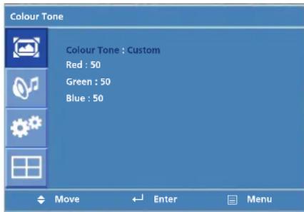
- Press Menu button.
Menu items appear on the screen.
- Press ← button to select "Picture" Icon.
"Picture Mode" is highlighted.
-
Press ▲ / ▼ buttons to move to "Colour Tone"
-
Press ▶ or , ∥ buttons to select "Colour Tone".
-
Press ▲ / ▼ buttons, then the menu changes in the following order.
Custom -> Cool2 -> Cool1 -> Normal -> Warm1 -> Warm2
-
Press EXIT button to escape OSD menu or press MENU button to return to the previous menu.
-
Custom : When the user wants to set the degree of RGB directly.
- Cool : For cool colors with bluish tone.
- Normal : For a general Colour Tone.
- Warm : For warm colors with reddish tone.
DIGITAL SIGNAGE
How to Set the Display Size
Users can adjust the display scale as they want
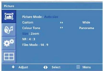

- Press Menu button. Menu items appear on the screen.
- Press ← button to select "Picture" Icon. "Picture Mode" is highlighted.
- Press ▲ / ▼ buttons to move to "Size".
- Press ◀ / ▶ or ↓ buttons and press ▲ / ▼ then the mode change in the following order.
AV/Component Inputs : Auto Size ->Wide -> Panorama -> Zoom -> 4 : 3 -> 14 : 9
PC input: Wide -> 4:3
-
Press EXIT button to escape OSD MENU or press MENU button to return to the previous menu.
-
Auto Size - Screen size adjust automatically by screen signal.
- Wide - General broadcast picture is adjusted to 16:9.
- Panorama - Picture enlarged to 16:9 format, letter box format.
- Zoom - Zoom in 16:9 in vertical direction
- 4 : 3 - 4 : 3 general picture size
- 14 : 9 - 14 : 9 picture size
- 1 : 1 - 1 : 1 real size
DIGITAL SIGNAGE
How to set image adjustment in PC mode (Supported only in PC mode)
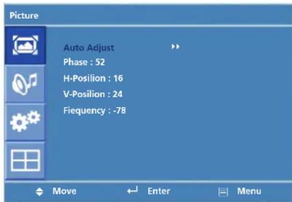
- Press Menu button. Menu items appear on the screen.
- Press ← button to select "Picture" Icon. "Picture Mode" is highlighted.
- Press ▲ / ▼ buttons to move to PC and press ▶ or ↙ buttons to select to "PC"
- "Auto Adjust" is high lighted.
- Press ↩ button to execute the "Auto Adjust"
-
Select the required option by pressing the ◀ / ▶ or , button, then press ◀ / ▶ button to adjust
-
Press EXIT button to escape OSD MENU or press MENU button to return to the previous menu.
-
Auto Adjust : Horizontal/vertical positions are automatically adjusted.
- Phase : To eliminate the shake of the picture.
- H-Position : To adjust the horizontal position of the picture.
- V-Position : To adjust the vertical position of the picture.
- Frequency : To eliminate the shake of picture.
How to Set Noise Reduction(NR)
How to Select the Audio Mode
DIGITAL SIGNAGE
User can eliminate noises on the screen in AV/Component/HDMI mode.(Not supported in PC mode)

- Press Menu button. Menu items appear on the screen.
- Press, button to select "Picture" Icon. "Picture Mode" is highlighted.
- Press ▲ / ▼ buttons to move to "NR".
- Press ◀ / ▶ buttons to select to "NR".
- Press ▲ / ▼ or ↓ buttons to set "On/Off".
- Press EXIT button to escape OSD MENU or press MENU button to return to the previous menu.
Users can adjust sound mode automatically as they want.

- Press Menu button. Menu items appear on the screen.
- Press ▲ / ▼ buttons to move to "Sound" Icon.
- Press ↓ button to select "Sound" Icon. "Mode" is highlighted.
- Press ▶ or ∥ buttons, to select to Sound mode. then the menu changes in the following order. Custom->Standard -> Music -> Movie -> Speech
-
Press EXIT button to escape OSD MENU or press MENU button to return to the previous menu.
-
Custom : When the user wants to set the values directly.
- Standard : For the general sound. Most audio contents are appropriate to this mode.
- Music : For enjoying original sound.
- Movie : Grandiose sound.
- Speech : Clear sound.
DIGITAL SIGNAGE
How to Adjust the Desired Audio Mode
Users can adjust sound mode automatically as they want.
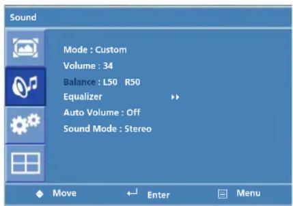

- Press Menu button. Menu items appear on the screen.
- Press ▲ / ▼ buttons to move to "Sound" Icon.
- Press , button to select "Sound" Icon. "Mode" is highlighted.
- Press ▲ / ▼ buttons to move to "Balance" or "Equalizer".
- Press , | buttons to select "Balance" or "Equalizer". Balance or Equalizer menu appears.
- Select required option by pressing the ▲ / ▼ buttons, then Press ◀ / ▶ buttons to adjust.
-
Press EXIT button to escape OSD MENU or press MENU button to return to the previous menu.
-
Balance : Adjusts the balance of left and right speakers.
- Equalizer : Adjusts the audio output signal in the desired band.
DIGITAL SIGNAGE
This function will automatically give a similar volume size to each channel.

- Press Menu button.
Menu items appear on the screen.
-
Press ▲ / ▼ buttons to move to "Sound" Icon.
-
Press ↓ button to select "Sound" Icon.
"Mode" is highlighted.
-
Press ▲ / ▼ buttons to move to "Auto Volume".
-
Press ◀ / ▶ or ↓ buttons to select "On/Off".
-
Press ▲ / ▼ or ↓ buttons to set to "On/Off".
-
Press EXIT button to escape OSD MENU or press MENU button to return to the previous menu
Depending on the particular program being broadcast, you can select stereo or mono.

- Press Menu button.
Menu items appear on the screen.
-
Press, button to select "Sound" Icon. "Mode" is highlighted.
-
Press ▲ / ▼ buttons to move to "Sound Mode".
-
Press ▶ or , buttons to select to "Sound Mode".
-
Press ▲ / ▼ buttons to select to "Stereo", "Mono L" or "Mono R."
-
Press exit button to escape OSD MENU or press MENU button to return to the previous menu
- Choose "Stereo" for channels that are broadcasting in Stereo.
- Choose "Mono" for channels that are broadcasting in Mono, or if you are having difficultly receiving a Stereo signal.
DIGITAL SIGNAGE
How to Reset
How to Set Clock, Sleep Time, ON/OFF Time

- Press Menu button. Menu items appear on the screen.
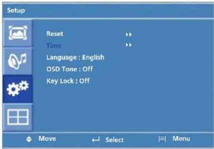
- Press , button to select "Setup" Icon. "Reset" is highlighted.
- Press ▶ or ↓ buttons to select to "Reset".
- Press, buttons to choose to "Reset".
- Press EXIT button to escape OSD MENU or press MENU button to return to the previous menu.
When you select "Reset" user setting Value will initialize.
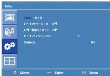
- Press Menu button. Menu items appear on the screen.
- Press ↓ button to select "Setup" Icon. "Reset" is highlighted.
- Press ▲ / ▼ buttons to move to "Time".
- Press ▶ or , buttons to select "Time". Time menu appears, then "Clock" is highlighted.
- Press ◀ / ▶ buttons to move between Hour, Minute and Press ▲ / ▼ buttons to set Hour, Minute.
When the power supply(AC main power) is cut off, the clock is reset to the value before the Timer set.
DIGITAL SIGNAGE
-
Press ▲ / ▼ buttons to move to "On or Off Timer".
-
Press ▶ or ↓ buttons to select "On or Off Timer".
-
Press ◀ / ▶ buttons to move between Hour, Minute and on/off and Press ▲ / ▼ buttons to set Hour, Minute and on/off
-
Press ▲ / ▼ buttons to move to "On Time Volume".
-
Press ◀ / ▶ buttons to adjust Volume.
- Press ▲ / ▼ buttons to move to "Source"
- Press ▶ or ↓ buttons to select to "Source"
- Press ▲ / ▼ buttons to set to Source

- Press Menu button.
Menu items appear on the screen. - Press , button to select "Setup" Icon.
"Reset" is highlighted. - Press ▲ / ▼ button to move to "Language" and press ▶ or , button to select to Language.
- Press EXIT button to escape OSD MENU or press MENU button to return to the previous menu.
Choosing the Your Languages
DIGITAL SIGNAGE
How to set OSD tone
How to Set Key-Lock

- Press Menu button. Menu items appear on the screen.
- Press ← button to select "Setup" Icon. "Reset" is highlighted.
- Press ▲ / ▼ buttons to move to "OSD Tone"
- Press ▶ or , button to select to "OSD Tone".
- Press ▲ / ▼ or ← buttons to set to "On/Off".
User can lock the control buttons on the front bottom of the Monitor.

- Press Menu button. Menu items appear on the screen.
-
Press ▲ / ▼ button to move to "Setup" Icon.
-
Press , button to select "Setup" Icon. "Reset" is highlighted
-
Press ▲ / ▼ buttons to move to "Key Lock".
-
Press ▶ or ← buttons to select to "Key Lock".
-
Press ▲ / ▼ or ← buttons to set to "On/Off".
-
Press EXIT button to escape OSD MENU or press MENU button to return to the previous menu.
DIGITAL SIGNAGE
How to Set the Multi Function
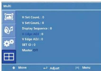

- Press Menu button.Menu items appear on the screen.
- Press ▲ / ▼ button to move to "Multi" Icon.
- Press ← button to select "Mutli" Icon. "Mutli Function" is highlighted
- Press ▲ / ▼ buttons to set up and change the location of the screen to be displayed. H Set Count/V Set Count/Display Sequence / H Edge ADJ / V Edge ADJ / SET ID/ Master
(Example of installation) install 3x2 with 6 units
| Product 1 Product 2 Product 3 | |
| Product 4 Product 5 Product 6 |
DIGITAL SIGNAGE
Set up Value
| installation item Product 1 Product 2 Product 3 Product 4 Product 5 Product 6 | |||||
| H Set Count | 3 3 3 3 3 3 | ||||
| V Set Count | 2 2 2 2 2 2 | ||||
| Display Sequence | 1 2 3 4 5 6 | ||||
| H Edge ADJ / V Edge ADJ | These are the set up value to make up the un-displayed area of Bezel Part. It can be adjustable according to the contents | ||||
| SET ID | It is necessary to control via RS232 communication port on PC. But do not need to set up or change when they are not controlled by PC | ||||
| Master | You are recommended to use the Master on state only one of products that you are using | ||||
[Cautions]
- In case of connecting the products in series from the input device (HDMI, analog RGB, component, video etc.), up to about 25 units are possible. But, the number of connecting devices can be different from the input signal level of each device and thereby amplified distributor can be needed for this product.
(when over 25 units are connected, the screen may not be displayed properly)
- You are recommended to use the component and progressive frequency of digital RGB in case of using multi-vision function.
(It may not be displayed properly when using Video input and interlace frequency)
DIGITAL SIGNAGE
How to Set the Heat Control
"Heat control" allows you set up fan operation according to interior temperature of the product


- Press Menu button. Menu items appear on the screen.
- Press ▲ / ▼ button to move to "Multi" Icon.
- Press, button to select "Multi" Icon. "Multi Function" is highlighted
- Press ▲ / ▼ buttons to move to "Heat Control".
- Press ▶ or , | buttons to set up and change the Heat Control.
"Fan Control" - AS the fan operation options, following 3 options are available
- Off : Fan is idle in Off status.
- On : Fan is working in On-status.
- Auto : Fan start working when the working temperature is higher than the measured temperature.
- Fan active Temp -set up value to start the fan.
- Hysteresis- tolerance value of fan operation temperature.
• Temperature- measured current temperature by sensor affixed to PCB'A
DIGITAL SIGNAGE
Diagnosis
When the product is not working properly, please check before you call customer center.
| Symptoms How to solve the problem | |
| Screen displays late after the power is on. | It happens not to show the screen noise when the power is on. Therefore it is not a defect. But if the screen doesn't show up within 5 minutes from turning on, please contact the customer center. |
| The screen is too dark or bright? | Adjust the brightness or contrast. |
| The screen doesn't show up indicating "Out of range". | You are using a signal which is outside the operating frequencies of the product (Unsupported), please change you video signal. |
| when the screen is scrambled. | please check the cable connection and the signal generator and contact customer center. |
| Automatic switching-on function is not working / the input data were disappeared when reboot the system after setting up the time | Automatic switching-on function is working when the product has been turned off via remote control or power button on main body. It is because that the set-up values are deleted when the power cord is unplugged. |
| The screen and sound are not synchronized | Check if the power is on, suspended or is correctly plugged into the outlet. Plug the power cord of other peripheral device to the outlet that the product is being connected. |
DIGITAL SIGNAGE
| Symptoms How to solve the problem | |
| The screen displays without the sound. | check the volume up and down with remote control and audio connection cable |
| No sound from either right speaker or left speaker. | Confirm the status of the sound balance on OSD menu and check the connection of speaker cable. |
| Remote control doesn't work. | Check if any foreign substances in the sensor and the polarity of battery inserted. If the batteries are drained, replace them with new batteries. |
| PC D-SUB doesn't work. | Set up the resolution referring to frequency table of input terminal. And re-boot the system as it supports Plug and Play. |
| Fan on the rear doesn't work | Check the status of temperature control on OSD menu |
| The screen doesn't show up when display the multi-vision. | check if it is set up to video input. Confirm if Interlace Timing was inputted. ( Refer to the cautions on Page 31 ) |
- If any problem unsolved by above diagnosis, please call customer center.
DIGITAL SIGNAGE
Specifications
D320ML(I/G)/D400ML/
D420ML(I/G/P/T)/
D460ML(I/G/P/T/H)/
D468ML(I/G/P/T/H)/D460SL(I)
| Model | D320ML(I/G) / D400ML / D420ML(I/G/P/T) / D460ML(I/G/P/T/H) / D468ML(I/G/P/T/H) / D460SL(I) |
| LCD | 1366 x 768 Pixel (HD) |
| Screen size (HxV/mm) | D320ML(I/G) : 697.7 x 392.3 / Pixel pitch 0.51D400ML : 885.2 x 497.7 / Pixel pitch 0.65D420ML(I/G/P/T) : 930.3 x 523.0 / Pixel pitch 0.68D460ML(I/G/P/T/H), D468ML(I/G/P/T/H) : 1018.4x572.5 / Pixel 0.75D460SL(I) : 1018.4x572.5 / Pixel 0.75 |
| Recommended resolution | 1360 x 768 @60Hz |
| Input | Digital RGB, Analog RGB, Component(Option), Video(Option), PC Audio L/R Component Audio L/R(Option), Video Audio L/R(Option), RS232C |
| Output | Digital RGB, Analog RGB, Component(Option), Video(Option), Audio L/R, RS232C |
| Power | AC 100- 240V 50/60Hz |
| Consumption (Typical) | D320ML(I/G) :170W / D400ML :200W / D420ML(I/G/P/T) :220W / D460ML(I/G/P/T/H), D468ML(I/G/P/T/H) :260W / D460SL(I) :260W |
| Control type | Remote control, key control |
- Above specification may be changed without prior notification for quality improvement.
DIGITAL SIGNAGE
Specifications
D405ML(I/G)/D407ML(I/G/P/T)/ D425ML(I/G/P/T)/D465ML(I/G)/ D467ML(I/G/P/T)/D525ML(I/G)/ D825ML(I/G)/D525SL(I)/ D705ML(I/G)/D705SL(I)/ D825SL(I)
| Model | D405ML(I/G)/D407ML(I/G/P/T)/D425ML(I/G/P/T)/D465ML(I/G)/D467ML(I/G/P/T)/D525ML(I/G)/D825ML(I/G)/ D525SL(I)/D705ML(I/G)/D705SL(I)/D825SL(I) |
| LCD | 1920 x 1080 Pixel (Full HD) |
| Screen size (HxV/mm) | D405ML(I/G): 885.6 x 498.15 / Pixel pitch 0.46D407ML(I/G/P/T): 885.2 x 497.7 / Pixel pitch 0.46D425ML(I/G/P/T): 930.25 x 523 / Pixel pitch 0.4845 x 0.4845D465ML(I/G): 1018.08 x 572.67 / Pixel pitch 0.53D467ML(I/G/P/T): 1018.4 x 572.5 / Pixel pitch 0.53D525ML(I/G): 1152.00 x 684.00 / Pixel pitch 0.60D825ML(I/G): 1806 x 1015 / Pixel pitchD525SL(I): 1152.00 x 684.00 / Pixel pitch 0.60D705ML(I/G), D705SL(I): 1549.44 x 871.56 / Pixel pitch 0.81D825SL(I): 1806 x 1015 / Pixel pitch |
| Recommended resolution | 1920 x 1080 @ 60Hz |
| Input | Digital RGB, Analog RGB, Component(Option), Video(Option), PC Audio L/R, Component Audio L/R(Option), Video Audio L/R(Option), RS232C |
| Output | Digital RGB, Analog RGB, Component(Option), Video(Option),Audio L/R, RS232C |
| Power | AC 100- 240V 50/60Hz |
| Consumption (Typical) | D405ML(I/G): 200W / D407ML(I/G/P/T), D425ML(I/G/P/T): 260W /D465ML(I/G), D467ML(I/G/P/T): 250W /D525ML(I/G), D825ML(I/G): 320W /D705ML(I/G), D705SL(I): 800W / D825SL(I): 900W |
| Control type | Remote control, key control |
- Above specification may be changed without prior notification for quality improvement.
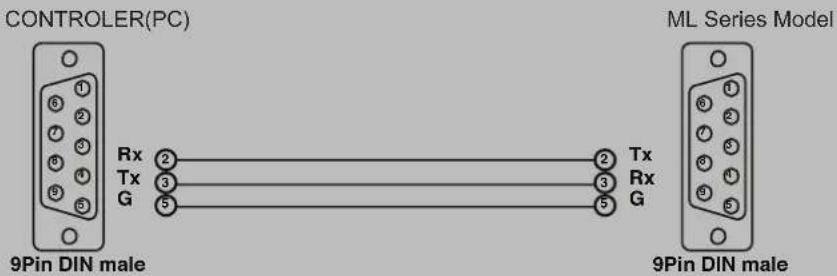
- SPEED : 9600 Baud/s, 8 bit, No parity, 1 Stop bit.
- REMOTE CONTROL WAVE FORM
1) Remote Control System Infrared rey system
fosc=455KHZ fc=fosc/2=37.917KHZ
2) Signal code
2-1) Transmission
- One pulse

- Bit Description
Bit "0"

Bit "1"

- Flame Interval

3. REMOTE CONTROL KEY CODE TABLE
DATA LAYOUTCustom Code : 7788H
| KEY DATA | |
| POWER 0x80 | |
| MENU 0x95 | |
| EXIT 0x96 | |
| SOURCE 0xAC | |
| ENTER 0x8C | |
| UP 0x8D | |
| DOWN 0x8E | |
| LEFT 0x8F | |
| RIGHT 0x90 |
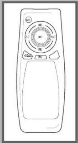
4. COMMAND FORMAT
* SET ID must select from the OSD menu and can't be select through the COMMAND.
* Only one unit can be set as Master unit, select Master ON from the OSD Menu. (DEFAULT OFF)
* For viewing COMMAND from Hyper Terminal windows, One unit must set as MASTER ON
| HEADER | SET ID | COMMAND TYPE | END |
| did: x- or all- | Command |
| did:1-pf. | To power off set that is SET ID 1 |
| did:all-fr. | To factory reset all set |
| did:2-fn. | To fan on set that is SET ID 2 |
- COMMAND TYPE
| Command Description | |
| pn / pf | Power on / Power off |
| fn / ff | Fan on / Fan off |
| fr | Factory reset |
| sd / sp / sc / sa | Source change ( d:HDMI, p:PC, c:Component, a:AV ) |
| sbu / sbd | Sub-Brightness 1 step up / down |
| rou / rod | Red Offset 1 step up / down |
| gou / god | Green Offset 1 step up / down |
| bou / bod | Blue Offset 1 step up / down |
| scu / scd | Sub-Contrast 1 step up / down |
| rgu / rgd | Red Gain 1 step up / down |
| ggu / ggd | Green Gain 1 step up / down |
| bgu / bgd | Blue Gain 1 step up / down |
| blu / bld | BACKLIGHT Value 1 step up / down |
| chxvy | H Set Count is x, V Set Count is y |
| nhxvy | H Set window is x, V Set window is y |
| ehxvy | H Edge ADJ is x, V Edge ADJ is y |
| x ( figure ) | Display sequence no is x |
| cr | Enable Color Control Mode; Under Cr mode, user can set color value without Header command ex) ro120 : Red Offset 120, bg100 : Blue Gain 100 |
| ir | Enable Ir Mode, In IR Mode, user can use keyboard buttonsas remote controller |
| ps | Current power status check. If current power is on(off), Hyper Terminal windows display “Power On(Power Off)” message. |
| is | Current input source status check. If current input source is VGA, Hyper Terminal windows display “VGA Mode” message. |
- REMOTE CONTROL KEY CODE TABLE
| Key value Key value | |||
| q | quit ( from lr mode ) | t | volume up |
| p | power | v | volume down |
| u | up | r | mute |
| n | down | c | picturemode |
| j | left | l | sleep |
| k | right | d | sound |
| e | enter | s | s.mode |
| m | menu | y | info->display |
| x | exit | The others | quit ( from lr mode ) |
| i | input | ||
- REMOTE CONTROL KEY CODE TABLE
| Command Description | |
| did:all-wn=si. | Change all units 'Display sequence' to 'SET ID' |
| did:allfst-hxvy | Set all units to 'H SET Count' = x, 'V SET Count' = y, 'Display sequence' = 'Select to SET ID' |
- CONNECTION
HYUNDAI IT Service Center
GERMANY
Hyundai IT Germany SVC
Hessenring 13B D-64546
Mörfelden-Walldorf Germany
Tel: +49 (0) 180 591 313 4
Web: www.HyundaiT.eu
AUSTRIA/BENELUX
Hyundai IT Germany SVC
Hessenring 13B D-64546
Mörfelden-Walldorf Germany
Tel: +49 (0) 180 591 313 4
Web: www.HyundaiT.eu
FRANCE
Serrib
25 Rue Albert Camus 90006
BELFORT France
Tel: +33 (0) 892 681 337
Web: www.serrib.com
SWITZERLAND
Pictronic AG Electronic Repair Service
Aavorstadt 40, 5600
Lenzburg Switzerland
Tel:00800 498 632 47 or
+41(0)628929600
Web: www.pictronic.ch
USA
AVC Tech, INC
777 MARK STREET, WOOD
DALE, IL 60191
Tel: +1 630 595 0123
SWEDEN
ANOVO Nordic AB
Lugna Gatan 16S-721 36
VÄSTERÅS, Sweden
Tel: +46 (0) 859 002 600
Web: www.anovo.se
DENMARK
ANOVO Nordic AB
Lugna Gatan 16S-721 36
VÄSTERÅS, Sweden
Tel: +46 (0) 859 002 600
Web: www.anovo.se
FINLAND
ANOVO Nordic AB
Lugna Gatan 16S-721 36
VÄSTERÅS, Sweden
Tel: +46 (0) 859 002 600
Web: www.anovo.se
UK
Repair Tech Ltd
Unit 4B Westield Road, CV47
OJH Southam, Warwickshire,
England
Tel: +44 (0) 871 855 242 0
Email :
hyundai@repairtech.co.uk
Web: www.repairtech.co.uk
NORWAY
A Novo Norge AS
00044 Frascati RM (Italy)
Tel: +39 (0) 694 293 321
Web: www.hyundai.it
CZECH REPUBLIC
SIL Eastern Europe a.s.
Tesinska 1970/56, 710 00
Ostrava Czech Republic
Tel: +420 (0) 596 253 677
Web: www.sil.cz
SLOVENIA
Tech. d.o.o.
Ljubljanska Cesta 21D, 1241
Kamnik, Slovenia
Tel: +386 (0) 183 946 17
Web: www.tech.si
SPAIN
Imatge Professional
Av. de la Fama, 125
Pol. Ind. Almeda
08940-Barcelona (Spain)
Tel: +34 93 325 30 35
Web: www.zolter.com.pl
HUNGARY
PROFI SZERVIZ KÖZPONT KFT.
gardi Jeno U41, 1041
Budapest, Hungary
Tel: +361 (0) 814 811 9
Web: www.servicenet.it
GREECE
Alman Hellas Ltd
Ortansias 23, GR-13677
Acharnai, Athens, Greece
Tel: +302 102 409 150
Web: www.alman.gr
TURKEY
Multimedya

- DECLARATION OF CONFORMITY
- DIGITAL SIGNAGE
- Major features
- Safety Information
- Be sure to understand
- CAUSE
- PREVENTION
- COUNTERMEASURES
- Check the product list
- Proper location for product installation
- Title and function of each part
- Control Panel
- How to Connecting Digital RGB(HDMI)
- How to Connecting analog RGB (PC D-SUB)
- How to Connecting the component (Option)
- Adjusting OSD and explanation of its function
- Users can manually adjust their desired picture
- Users can adjust the display scale as they want
- How to Set Noise Reduction(NR)
- How to Select the Audio Mode
- User can eliminate noises on the screen in AV/Component/HDMI mode.(Not supported in PC mode)
- Users can adjust sound mode automatically as they want.
- How to Set the Multi Function
- [Cautions]
- Diagnosis
- Specifications
- REMOTE CONTROL KEY CODE TABLE
- COMMAND FORMAT
- HYUNDAI IT Service Center
- GERMANY
- AUSTRIA/BENELUX
- FRANCE
- SWITZERLAND
- USA
- SWEDEN
- DENMARK
- FINLAND
- UK
- NORWAY
- CZECH REPUBLIC
- SLOVENIA
- SPAIN
- HUNGARY
- GREECE
- TURKEY
Brand : HYUNDAI
Model : D465ML SP
Category : Screen