
SL2-141 - Router SIEMENS - Free user manual and instructions
Find the device manual for free SL2-141 SIEMENS in PDF.


| Product Type | ADSL2+ Wireless Router |
| Dimensions | 190mm (L) x 130mm (W) x 40mm (H) |
| Weight | 350 g |
| Power Supply | Input: 110-230 V AC; Output: 12 V AC, 1 A |
| Power Consumption | Less than 10 W |
| Interfaces | 1x RJ-11 ADSL, 4x RJ-45 10/100 Ethernet, 1x USB 1.1, 1x 802.11g Wireless |
| ADSL Standards | ANSI T1.413 Issue 2, ITU G.992.1/2/3/4/5 Annex A |
| ADSL2+ Downstream Rate | Up to 24 Mbps |
| ADSL2+ Upstream Rate | Up to 1.2 Mbps |
| Wireless Standard | IEEE 802.11g/b, up to 54 Mbps |
| Wireless Frequency | 2.4 - 2.5 GHz |
| Wireless Security | WEP 64/128-bit, WPA/WPA2, 802.1x, Access Control, SSID Hide |
| Routing Functions | NAT/PAT, DHCP Server/Client/Relay, DNS Relay, Dynamic DNS, Static Routes, RIP v1/v2 |
| Bridging Features | IEEE 802.1d Transparent Bridging, 802.1q VLAN |
| Firewall | IP Packet Filtering, DoS Protection, URL Filtering |
| Configuration | Web-based (HTTP), Telnet, SNMP v1/v2, Firmware Upgrade via HTTP/TFTP/FTP |
| LED Indicators | Power, DSL, PPP, Ethernet 1-4, WLAN, USB |
| Environment | Temperature: 0-40 °C; Humidity: 20-90% (non-condensing) |
| Certifications | FCC Part 15 Class B, CE, UL, CB, LVD |
| Spare Parts Included | Power Adapter, RJ-11 Cable, RJ-45 Cable, Quick Start Guide, Driver CD |
| Maintenance | Unplug before cleaning; use dry cloth; do not disassemble; contact qualified service personnel |
| Repairability | Do not attempt self-repair; contact qualified service personnel |
Frequently Asked Questions - SL2-141 SIEMENS
User questions about SL2-141 SIEMENS
0 question about this device. Answer the ones you know or ask your own.
Ask a new question about this device
Download the instructions for your Router in PDF format for free! Find your manual SL2-141 - SIEMENS and take your electronic device back in hand. On this page are published all the documents necessary for the use of your device. SL2-141 by SIEMENS.
USER MANUAL SL2-141 SIEMENS
SL2-141/SL2-141-I ADSL Router
User's Manual
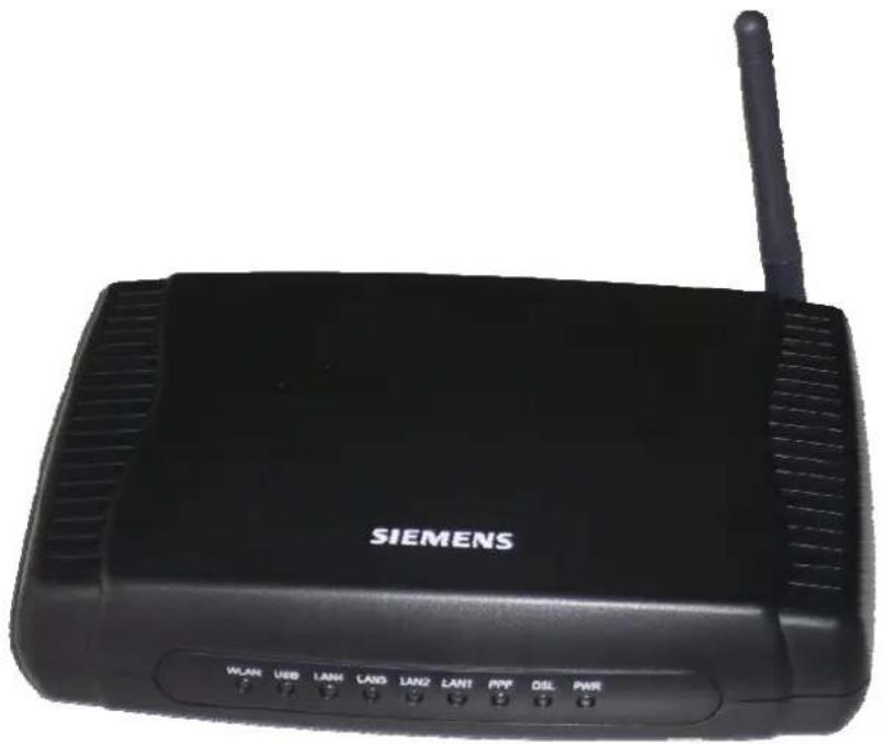
natural_image
Black Siemens Wi-Fi router with antenna and control buttons (no visible text beyond brand name)Rev: 1.5
2007/03/30
No part of this publication may be reproduced in any form by any means without the prior written permission. Other trademarks or brand names mentioned herein are trademarks or registered trademarks of their respective companies.
Safety Notes
For Installation
☐ Use only the type of power source indicated on the marking labels.
☐ Use only power adapter supplied with the product.
☐ Do not overload wall outlet or extension cords as this may increase the risk of electric shock or fire. If the power cord is frayed, replace it with a new one.
☐ Proper ventilation is necessary to prevent the product overheating. Do not block or cover the slots and openings on the device, which are intended for ventilation and proper operation. It is recommended to mount the product with a stack.
☐ Do not place the product near any source of heat or expose it to direct sunlight.
☐ Do not expose the product to moisture. Never spill any liquid on the product.
☐ Do not attempt to connect with any computer accessory or electronic product without instructions from qualified service personnel. This may result in risk of electronic shock or fire.
☐ Do not place this product on unstable stand or table.
For Using
☐ Power off and unplug this product from the wall outlet when it is not in use or before cleaning. Pay attention to the temperature of the power adapter. The temperature might be high.
☐ After powering off the product, power on the product at least 15 seconds later.
☐ Do not block the ventilating openings of this product.
☐ When the product is expected to be not in use for a period of time, unplug the power cord of the product to prevent it from the damage of storm or sudden increases in rating.
For Service
Do not attempt to disassemble or open covers of this unit by yourself. Nor should you attempt to service the product yourself, which may void the user's authority to operate it. Contact qualified service personnel under the following conditions:
☐ If the power cord or plug is damaged or frayed.
☐ If liquid has been spilled into the product.
☐ If the product has been exposed to rain or water.
☐ If the product does not operate normally when the operating instructions are followed.
☐ If the product has been dropped or the cabinet has been damaged.
☐ If the product exhibits a distinct change in performance.
This equipment must be installed and operated in accordance with provided instructions and a minimum 20 cm spacing must be provided between computer mounted antenna and person's body (excluding extremities of hands, wrist and feet) during wireless modes of operation.
☐ This device complies with Part 15 of the FCC Rules. Operation is subject to the following two conditions: (1) this device may not cause harmful interference, and (2) this device must accept any interference received, including interference that may cause undesired operation.
☐ Any changes or modifications not expressly approved by the party responsible for compliance could void the authority to operate equipment.
Warning
Caution
FCC
This equipment must be installed and operated in accordance with provided instructions and a minimum 20 cm spacing must be provided between computer mounted antenna and person's body (excluding extremities of hands, wrist and feet) during wireless modes of operation.
FCC Class B Notice
This device complies with Part 15 of the FCC Rules. Operation is subject to the following two conditions:
(1) this device may not cause harmful interference, and
(2) this device must accept any interference received, including interference that may cause undesired operation.
Note: This equipment has been tested and found to comply with the limits for a Class B digital device, pursuant to Part 15 of the FCC Rules. These limits are designed to provide reasonable protection against harmful interference in a residential installation. This equipment can generate, use and radiate radio frequency energy and, if not installed and used in accordance with the instructions, may cause harmful interference to radio communications. However, there is no guarantee that interference will not occur in a particular installation. If this equipment does cause harmful interference to radio or television reception, which can be determined by turning the equipment off and on, the user is encouraged to try to correct the interference by one or more of the following measures:
● Reorient or relocate the receiving antenna.
- Increase the separation between the equipment and receiver.
- Connect the equipment into an outlet on a circuit different from that to which the receiver is connected.
- Consult the dealer or an experienced radio/television technician for help.
IC Statement
To prevent radio interference to the licensed service, this device is intended to be operated indoors and away from windows to provide maximum shielding. Equipment (or its transmit antenna) that is installed outdoors is subject to licensing
ICES-003 Class B Notice - Avis NMB-003, Classe B
This Class B digital apparatus complies with Canadian ICES-003.
Thank you for choosing the Asymmetric Digital Subscriber Line (ADSL) Router. With the asymmetric technology, this device runs over standard copper phone lines. In addition, ADSL allows you to have both voice and data services in use simultaneously all over one phone line.
SL2-141/SL2-141-I Wireless ADSL2+ Router is a DSL broadband access device which allows ADSL connectivity while providing 802.11g wireless LAN capabilities for home or office users. It supports ADSL2/ADSL2+ and is backward compatible to ADSL, even offers auto-negotiation capability for different flavors (G.dmt, G.lite, or T1.413 Issue 2) according to central office DSLAM's settings (Digital Subscriber Line Access Multiplexer). Also the feature-rich routing functions are seamlessly integrated to ADSL service for existing corporate or home users. Now users can enjoy various bandwidth-consuming applications via SL2-141/SL2-141-I Wireless ADSL2+ Router.
Features
ADSL Compliance
ANSI T1.413 Issue 2
ITU G.992.1 Annex A (G.dmt)
ITU G.992.2 Annex A (G.lite)
ITU G.994.1 (G.hs)
Support dying gasp
Maximum Rate: 8 Mbps for downstream and 1 Mbps for upstream
ADSL2 Compliance
ITU G.992.3 Annex A (G.dmt)
ITU G.992.4 Annex A (G.lite)
Maximum Rate: 12 Mbps for downstream and 1 Mbps for upstream
ADSL2+ Compliance
ITU G.992.5 Annex A (G.dmt)
Maximum Rate: 24 Mbps for downstream and 1.2 Mbps for upstream
Wireless LAN Compliance Features
IEEE 802.11g and IEEE 802.11b
Data Rate: 54, 48, 36, 24, 18, 12, 9, 6 Mbps for 802.11g/11, 5.5, 2, 1 Mbps for 802.11b
Modulation Technique: OFDM for 802.11g; CCK (11 Mbps, 5.5 Mbps) for 802.11b; DQPSK (2Mbps) for 802.11b; DBPSK (1 Mbps) for 802.11b
Network Architecture: infrastructure
Operating Frequency: 2.4 \~ 2.5 GHz
Operating Channels: depending on local regulations. For example, 11Channels (Northern America), 13 Channels (Europe), and 14 Channels (Japan)
RF Output Power: 13.5+/-1.5dBm for 802.11g; 17.5+/-1.5dBm for 802.11b
The output power can be adjustable.
Antenna Connectors: Hardware diversity support. One external and one internal antenna are provided.
Coverage Area: 300m
Support WEP (Wired Equivalent Privacy) mechanism which uses RC4 with 64-bit or 128-bit key length
Support 802.1x and WPA/WPA2
Support the Access Control function: only registered WLAN clients are allowed to associate to this device
SSID can be hidden for the security issue (Don't broadcast SSID)
Support the Repeater function to extend the coverage area
Support wireless user isolation for the hotspot
ATM Features
Compliant to ATM Forum UNI 3.1 / 4.0 Permanent Virtual Circuits (PVCs)
Support up to 16 PVCs for UBR, CBR, VBR-nrt, VBR-rt with traffic shaping
RFC2684 LLC Encapsulation and VC Multiplexing over AAL5
RFC2364 Point-to-Point Protocol (PPP) over AAL5
RFC2225 Classical IP and ARP over ATM
RFC2516 PPP over Ethernet: support Relay (Transparent Forwarding and Client functions)
Support PPPoA or PPPoE Bridged mode (the IP address got from ISP can be passed to the user's PC and behave as the IP address of the user's PC.)
OAM F4/F5 End-to-End/Segment Loopback Cells
Bridging Features
Supports self-learning bridge specified in IEEE 802.1D Transparent Bridging
Supports up to 4096 learning MAC addresses
Transparent Bridging among 10/100 Mb Ethernet and 802.11g wireless LAN
Support Virtual LAN function specified in IEEE 802.1q
Routing Features
Compliance to IPv4 which include RFC791, RFC792, RFC826, RFC768, and RFC793
NAT (Network Address Translation) / PAT (Port Address Translation) let multiple users (up to 128) on the LAN to access the Internet for the cost of only one IP address.
ALGs (Application Level Gateways): such as NetMeeting, MSN Messenger, FTP, Quick Time, mIRC, Real Player, CuSeeMe, VPN pass-through with multiple sessions, etc.
Port Forwarding: the users can setup multiple virtual servers (e.g., Web, FTP, Mail servers) on user's local network.
Support DMZ
UPnP IGD (Internet Gateway Device) with NAT traversal capability
Static routes, RFC1058 RIPv1, and RFC1723 RIPv2
DNS Relay, Dynamic DNS
DHCP Client/Relay/Server
Time protocol can be used to get current time from network time server
Support IGMP Proxy/Snoop
Support IP/Bridge QoS for prioritize the transmission of different traffic classes
Support port mapping function which allows you to assign all data traffic transmitted among specific Internet connections and LAN ports
Security Features
PAP (RFC1334), CHAP (RFC1994), and MS-CHAP for PPP session
Firewall support IP packets filtering based on IP address/Port number/Protocol type
∅ Bridge packet filtering (optional)
URL filtering (optional)
Support DoS (Deny of Services) which detect & protect a number of attacks (such as SYN/FIN/RST Flood, Smurf, WinNuke, Echo Scan, Xmas Tree Scan, etc)
Configuration and Management
User-friendly embedded web configuration interface with password protection
Remote management access control via HTTP, TFTP, FTP, Telnet, SSH, SNMP
Telnet session for local or remote management
Firmware upgrades through HTTP, TFTP, or FTP
The boot loader contains very simple web page to allow the users to update the run-time firmware image.
Configuration file backup and restore
SNMPv1/v2 agent with MIB-II, ADSL Line MIB
Unpacking
Check the contents of the package against the pack contents checklist below. If any of the items is missing, then contact the dealer from whom the equipment was purchased.
ADSL Router
Power Adapter and Cord
RJ-11 ADSL Line Cable
RJ-45 Ethernet Cable
Quick Start Guide
Driver & Utility Software CD
Subscription for ADSL Service
To use the ADSL Router, you have to subscribe for ADSL service from your broadband service provider. According to the service type you subscribe, you will get various IP addresses:
Dynamic IP: If you apply for dial-up connection, you will be given an Internet account with username and password. You will get a dynamic IP by dialing up to your ISP.
Static IP address: If you apply for full-time connectivity, you may get either one static IP address or a range of IP addresses from your ISP. The number of IP addresses varies according to different ADSL service provider.
Chapter 1: Overview
This chapter provides you the description for the LED and connector for front and rear view of the router. Before you use/install this router, please take a look at this information first.
Physical Outlook
Front Panel
The following illustrations show the front panel of the ADSL Router (with USB interface and without USB interface):
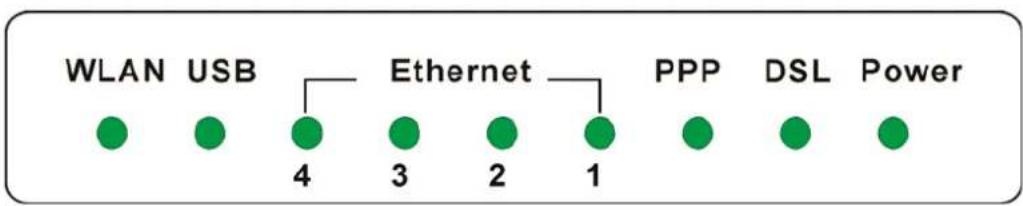
LED Indicators
The ADSL Router is equipped with five LEDs on the front panel as described in the table below (from left to right):
| LED Status Description Color | |||
| WLAN | Green | Unlit Power off or no radio signal (WLAN card is not present or fails to function). | |
| Blinking Traffic is going through Wireless LAN interface. | |||
| Solid Wireless LAN interface ready to work. | |||
| Unlit Power off or wait for USB connection going up. USB Green | |||
| Blinking User data is going through USB port. | |||
| Solid USB connection is OK. | |||
| Ethernet 1 - 4 | Green | Unlit Power off or no Ethernet carrier is present. | |
| Blinking Ethernet carrier is present and user data is going through Ethernet port. | |||
| Solid Ethernet carrier is present. | |||
| PPP | Green | Unlit No PPPoA or PPPoE connection | |
| Solid At least one PPPoA or PPPoE connection is up. The users can access the Internet now. | |||
| DSL | Green | Unlit Power off or ADSL line connection is handshaking or training is in progress. | |
| Blinking User data is going through ADSL port. | |||
| Solid ADSL line connection is OK. | |||
| LED Color Status Description | |||
| Power | Green | Unlit | Power off. |
| Solid | Power on. | ||
Rear Panel
The following figures illustrate the rear panel of your ADSL Router.
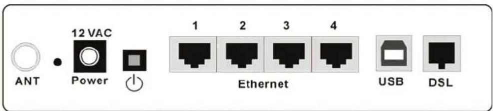
| Connector | Description |
| 12VAC | 12VAC Power connector |
| ➊ | Power switch |
| Ethernet 1-4 | Ethernet RJ-45 connector |
| USB | USB connector (for the model with USB interface only) |
| DSL | RJ-11 connector |
Chapter 2: System Requirement and Installation
System Requirement
To access the ADSL Router via Ethernet, the host computer must meet the following requirements:
With Ethernet network interface.
Must have TCP/IP installed.
Set client PC with obtain an IP address automatically or set fix IP address.
With a web browser installed: Internet Explorer 5.x or later.
The ADSL Router is configured with the default IP address of 192.168.1.1 and subnet mask of 255.255.255.0. As the DHCP server is Enable by default, The DHCP clients should be able to access the ADSL Router. Or you could assign an IP address to the host PC first for initial configuration.
You also can manage the ADSL Router through a web browser-based manager: ADSL ROUTER CONTROL PANEL. The ADSL Router manager uses the HTTP protocol via a web browser to allow you to set up and manage the device.

To configure the device via web browser, at least one properly-configured PC must be connected to the network (either connected directly or through an external hub/switch to the LAN port of the device).
Choosing a place for the ADSL Router
1 Place the ADSL Router close to ADSL wall outlet and power outlet for the cable to reach it easily.
Avoid placing the device in places where people may walk on the cables. Also keep it away from direct sunlight or heat sources.
③ Place the device on a flat and stable stand.
Connecting the ADSL Router
Follow the steps below to connect the related devices.
① Connecting the ADSL line. Connect the DSL port of the device to your ADSL wall outlet with RJ-11 cable.
② Please attach one end of the Ethernet cable with RJ-45 connector to the LAN port of your ADSL Router.
3 Connect the other end of the cable to the Ethernet port of the client PC.
4 Connect the supplied power adapter to the PWR port of your ADSL Router, and plug the other end to a power outlet.
⑤ Turn on the power switch.
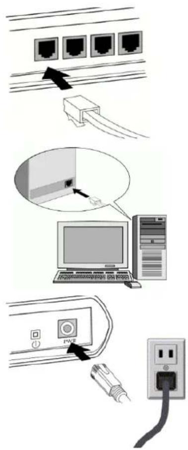
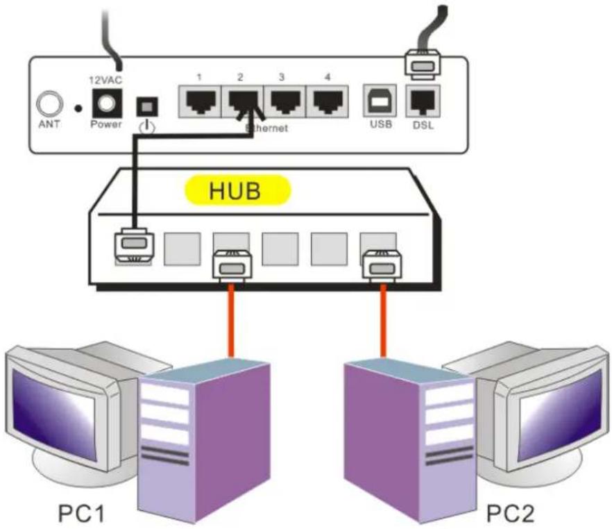
For connecting through a hub, please refer to the following diagram for an example.
Install the USB Driver
For Windows ME
1 Run the USB installation program from the CD provided by your device package.
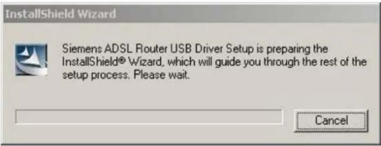
② An InstallShield Wizard will appear. Please wait for a moment.
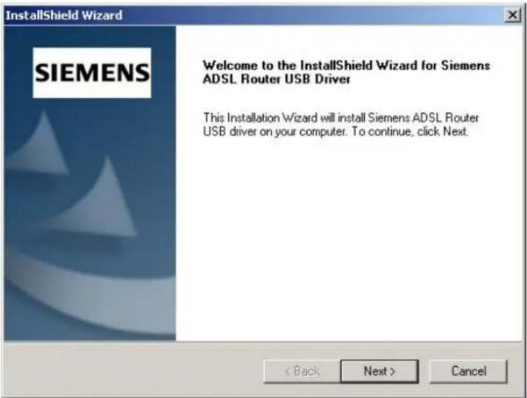
③ When the welcome screen appears, click Next for next step.
4 When the InstallShield Wizard Complete appears, click Finish.
⑤ Plug the USB cable between your device and PC.
Note: If the USB device is not detected, check the USB cable between the PC and the device. Also verify that the device is power on.
⑥ The system will detect the USB driver automatically. Now, the system will copy the proper files for this device.
⑦ When the file copying finished, the dialog above will close. Now the USB driver is installed properly. You can use the device.
For Windows 2000
1 Run the USB installation program from the CD provided by your device package.
② An InstallShield Wizard will appear. Please wait for a moment.
③ When the welcome screen appears, click Next for next step.
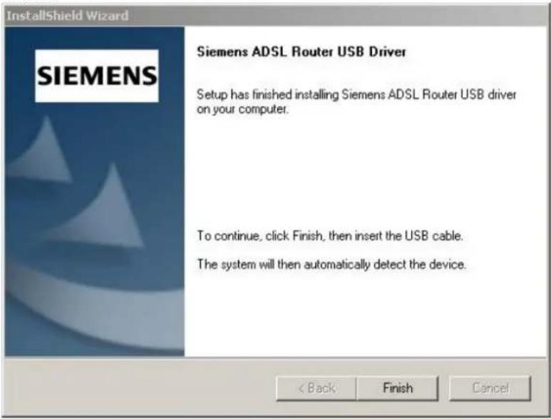
4 When the InstallShield Wizard Complete appears, click Finish.
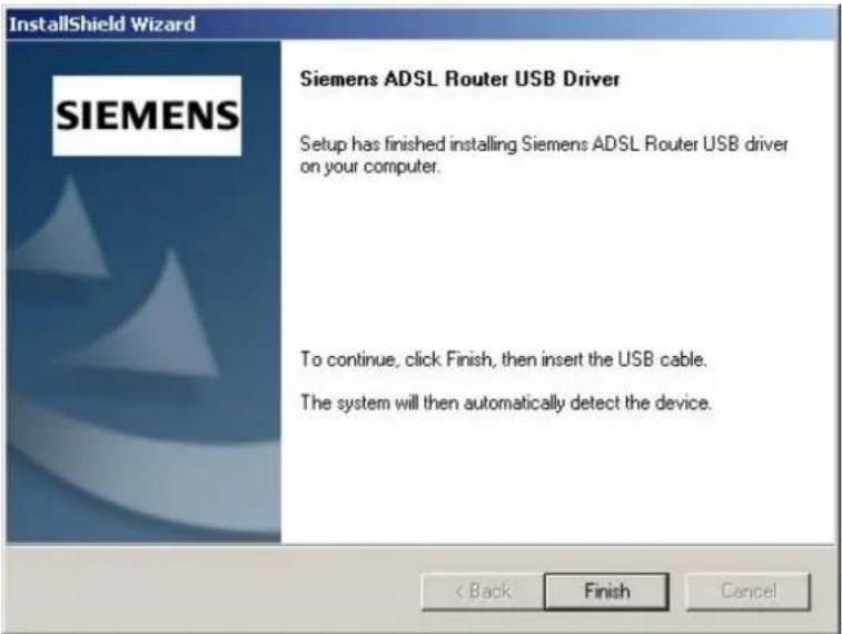
⑤ Plug the USB cable between your device and PC.
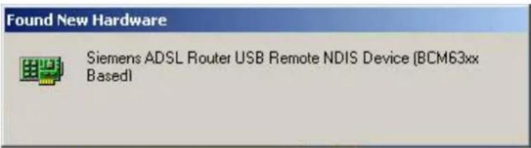

Note: If the USB device is not detected, check the USB cable between the PC and the device. Also verify that the device is power on.
⑥ The system will detect the USB driver automatically. Now, the system will copy the proper files for this device.
When the file copying finished, the dialog above will close. The InstallShield Wizard Complete appears, click Finish. Now the USB driver is installed properly. You can use the device.
For Windows XP
1 Run the USB installation program from the CD provided by your device package.
② An InstallShield Wizard will appear. Please wait for a moment.
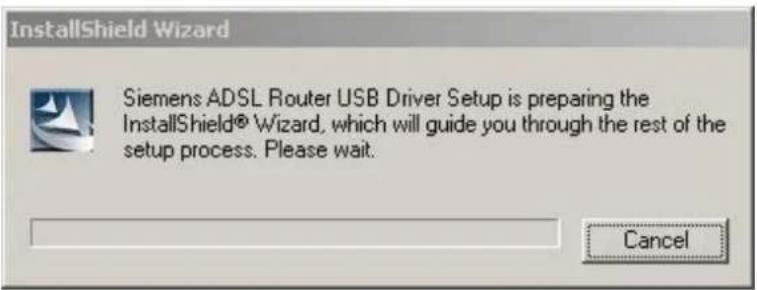
③ When the welcome screen appears, click Next for next step.
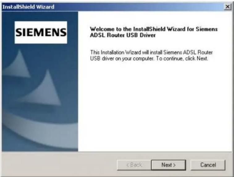
4 When the InstallShield Wizard Complete appears, click Finish.
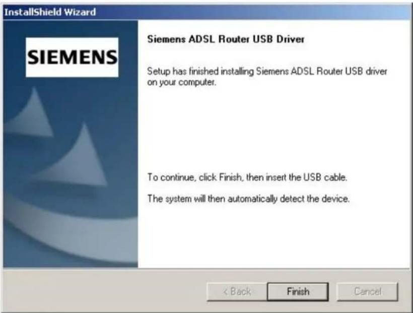
⑤ Plug the USB cable between your device and PC.

Note: If the USB device is not detected, check the USB cable between the PC and the device. Also verify that the device is power on.
⑥ The system will detect the USB driver automatically.
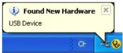
⑦ The system is trying to find proper driver for your device and copying the files automatically.
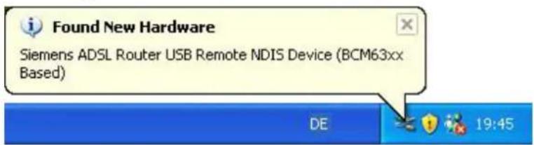
8 After the file copying is finished, a completing message will appear.
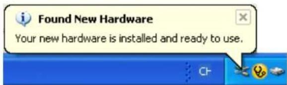
⑨ You can use the device now.
For Windows Vista
For Vista users, please press Continue whenever a prompted window asking for permission to continue during USB driver installation process (see the figure below for example).
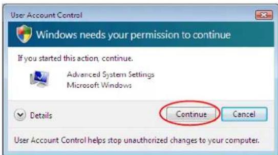
To install the USB driver before connect the router to the PC, here provides two methods.
Method One - Use the driver CD came with the product package.
① Run the USB installation program on the CD provided in your router package.
② An InstallShield Wizard will appear. Please wait for a moment.
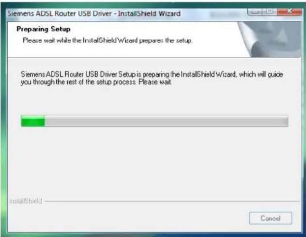
③ When the welcome screen appears, click Next for the next step.
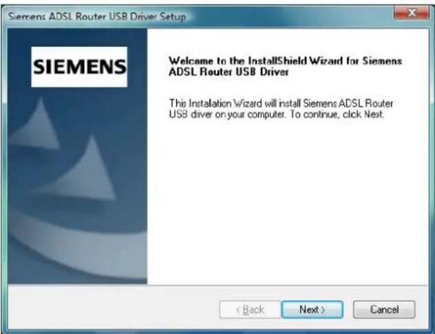
4 When the complete message of InstallShield Wizard appears, click Finish.
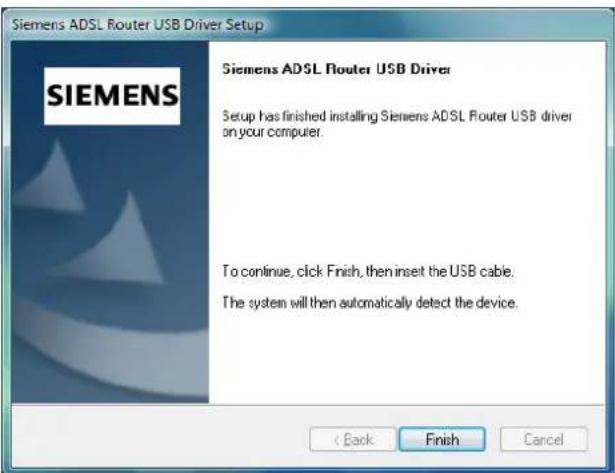
⑤ Link your router and the PC with a USB cable.
⑥ The system will detect the USB driver automatically.
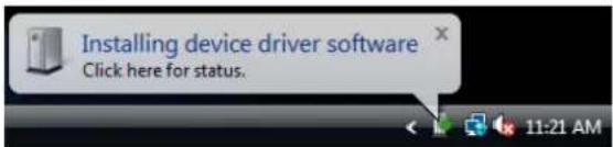

Note: If the USB device is not detected, check the USB cable between the PC and the device. Also make sure that the device is power on.
7 After the file copying finished, a completing message will appear.

⑧ You can use the router now.
Method Two - Run a silent installation.
① Copy the USB driver folder from the driver CD to somewhere on the PC. (In our example, the driver files are put under D:\Siemens WHQLed.)
② Open Start menu, key in cmd in the blank and press enter. Then click cmd.
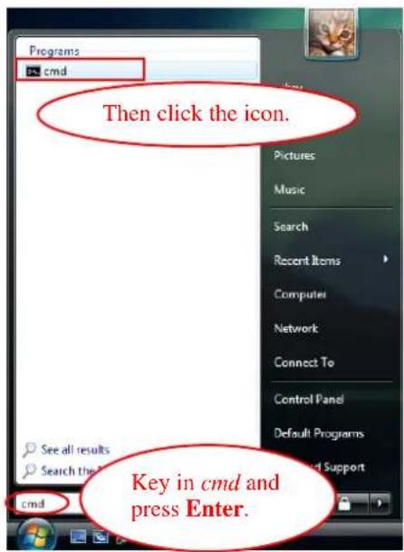
③ When the Command Prompt screen appears, point to the driver folder on your PC, and then enter setup -s. Press enter to start silent installation.
![Microsoft Windows [Version 6.0.6000] Copyright (c) 2006 Microsoft Corporation. All rights reserved. C:\Users\askey>d: D:\>cd "Siemens WHQLed" D:\Siemens WHQLed>setup -s](/content/2026/05/1021346/images/ca4d836e787b0cd27606d11eb0e469976e61fdff8b81dcec109d475c5faffdd5.jpg)
4 The system will install the driver automatically. You can connect your router and the PC with a USB cable now.
⑤ The system will detect the USB driver automatically.
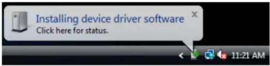

Note: If the USB device is not detected, check the USB cable between the PC and the device. Also make sure that the device is power on.
⑥ After the file copying finished, a completing message will appear.

⑦ You can use the router now.
Method Three – If the USB driver has not been installed yet, you can also connect the router to the PC with a USB cable and wait for Universal Plug and Play device to detect the router, and then install the driver.
① Plug the USB cable into the USB port on the PC.
② A Found New Hardware window will appear. Press Locate and install driver software (recommended).
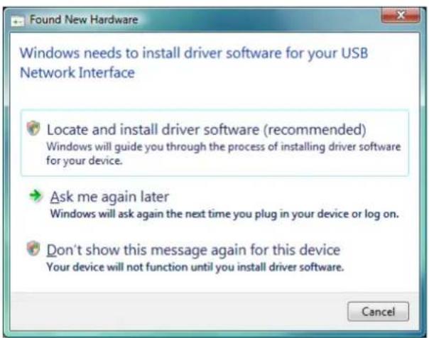
③ Then insert the USB driver CD provided in your router package into the PC, and press Next.
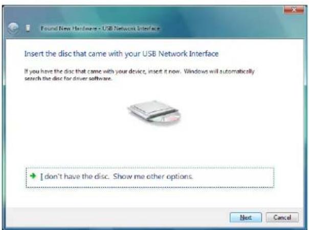
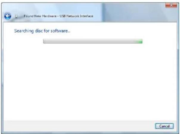
4 The system will search disc for the USB driver needed and then complete the installation.
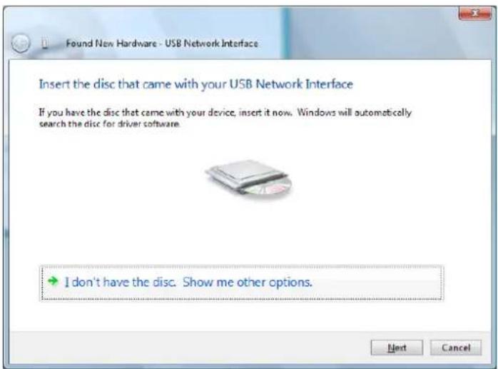
Or if you do not have a disc, but have the driver files on your PC, you can follow the steps below:
③ Press I don't have the disc. Show me other options.
4 Select Browse my computer for driver software (advanced).
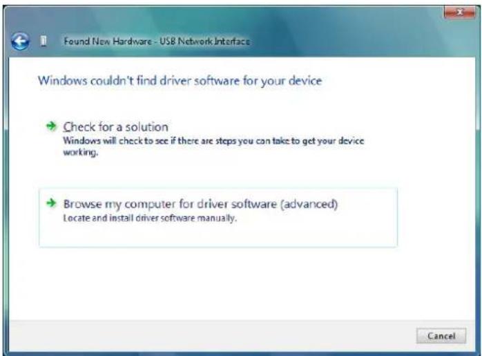
5 Press Browse to set the path for the driver file, and then press Next.
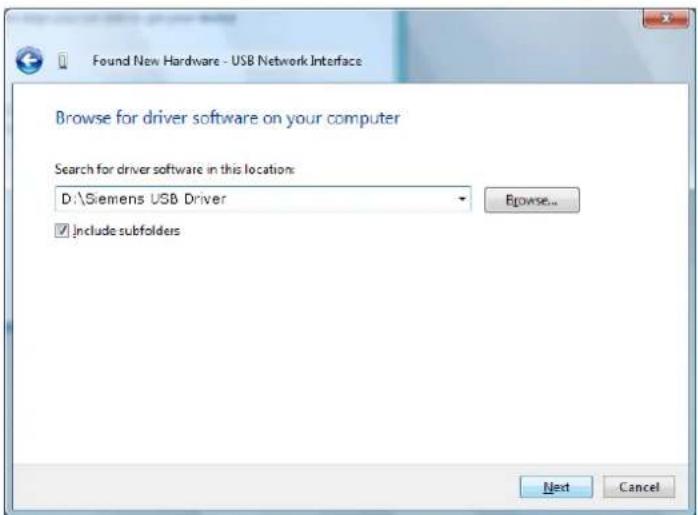
⑥ Wait while the system installing the driver.
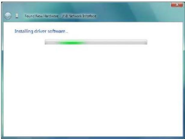
Now the driver software is installed successfully. Press Close to start using the router.
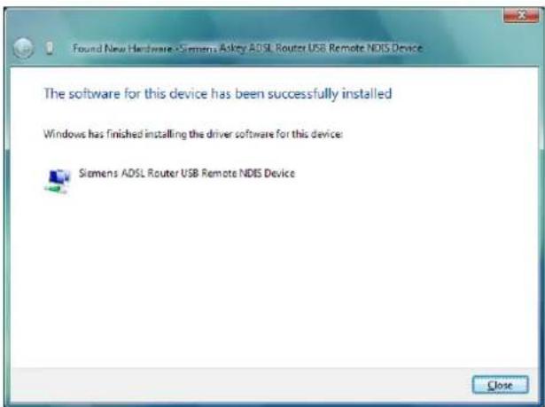
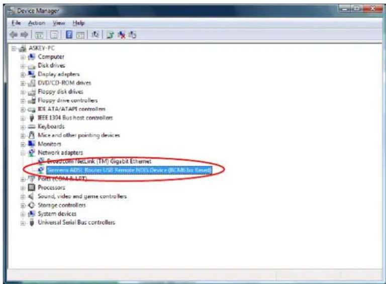
To make sure the USB driver for your router is properly installed, please do the following steps.
- Open the Start menu and press Control Panel.
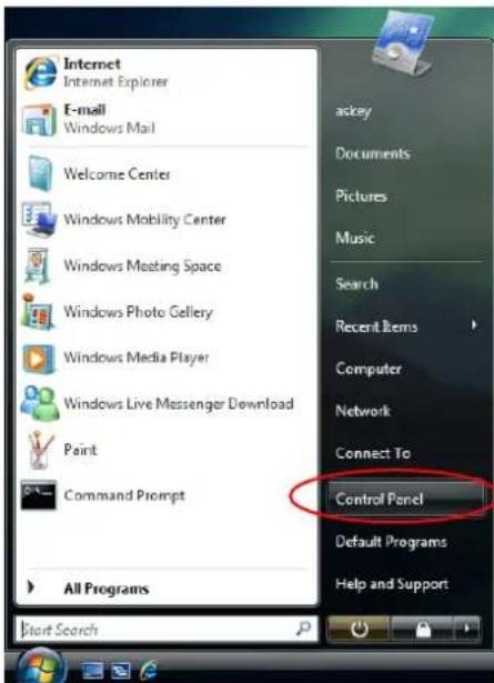
- On the Control Panel folder, click System and Maintenance.
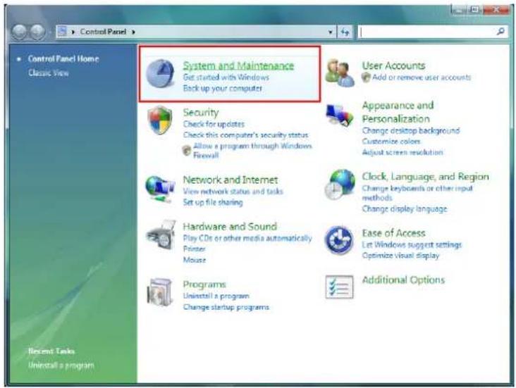
3. Press System.
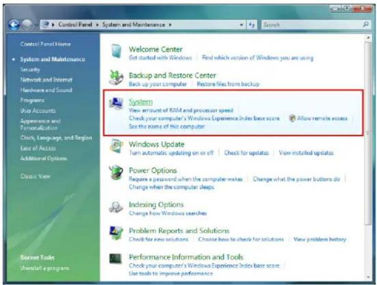
4. Click Device Manager.
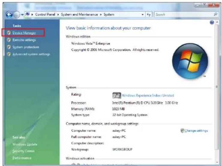
5. Confirm that the Siemens ADSL Router USB Remote NDIS Device (BCM63xx Based) is
on the Network adapters list.
Uninstall the USB Driver
For Windows ME
For uninstall the USB driver, please do the following.
The first way:
Choose Programs – Siemens Broadband – Uninstall Siemens ADSL Router USB Driver from the Start menu.
② The InstallShield Wizard dialog will appear.
③ A dialog appears to ask you confirm if you want to remove the USB driver or not. Please click Ok.
④ Unplug the USB cable between your device and your PC.
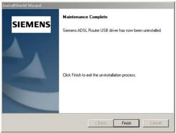
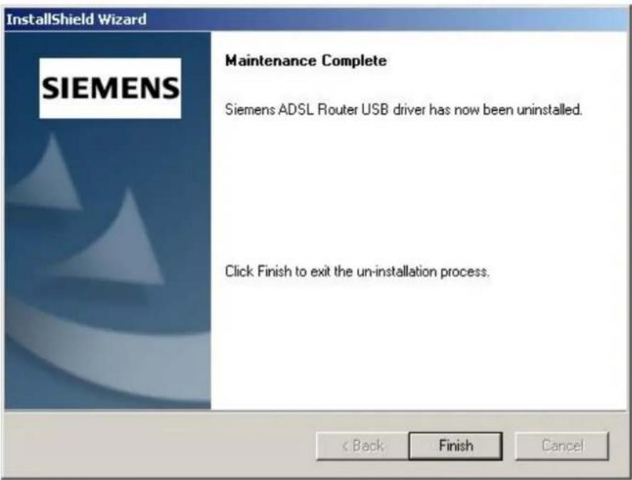
⑤ When the Maintenance Complete screen appears, the USB driver is removed successfully. Click Finish.
The second way:
Choose Settings – Control Panel from the Start menu. Choose Add/Remove Programs.
② A dialog appears to ask you choose the program that you want to remove. Please select Siemens ADSL Router USB Driver and click Change/Remove.
③ The InstallShield Wizard dialog will appear.
4 Unplug the USB cable between your device and your PC. Then click OK.
⑤ When the Maintenance Complete screen appears, the USB driver is removed successfully. Click Finish
For Windows 2000
For uninstall the USB driver, there are two ways to do it. Please do as the following:
The first way:
Choose Programs – Siemens Broadband – Uninstall Siemens ADSL Router USB Driver from the Start menu.
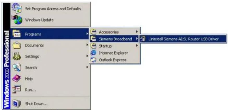
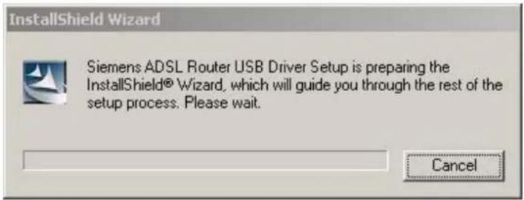
② The InstallShield Wizard dialog will appear.
③ A dialog appears to ask you confirm if you want to remove the USB driver or not. Please click Ok.
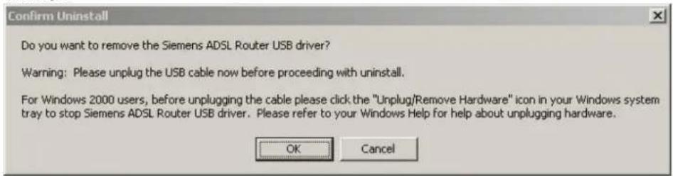
④ Unplug the USB cable between your device and your PC.
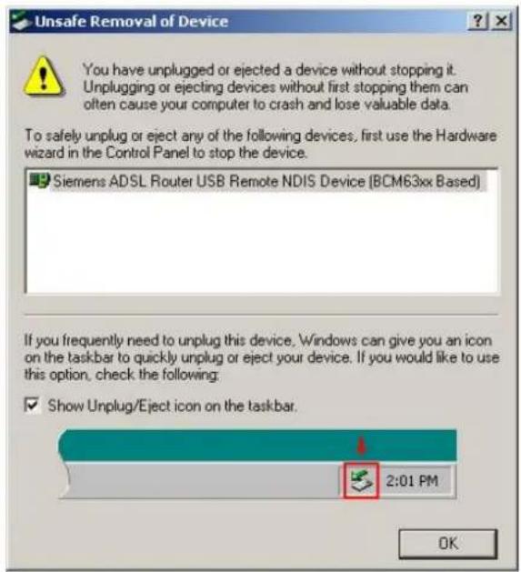
⑤ When the Unsafe Removal of Device screen appears, the USB driver is removed successfully. Click OK.
⑥ When the Maintenance Complete screen appears, the USB driver is removed successfully. Click Finish.
The second way:
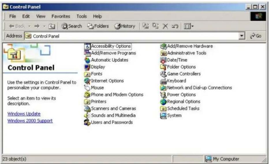
Choose Settings – Control Panel from the Start menu. Choose Add/Remove Programs.
② A dialog appears to ask you choose the program that you want to remove. Please select Siemens ADSL Router USB Driver and click Change/Remove.
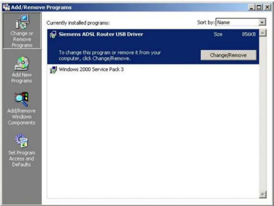
③ The InstallShield Wizard dialog will appear.
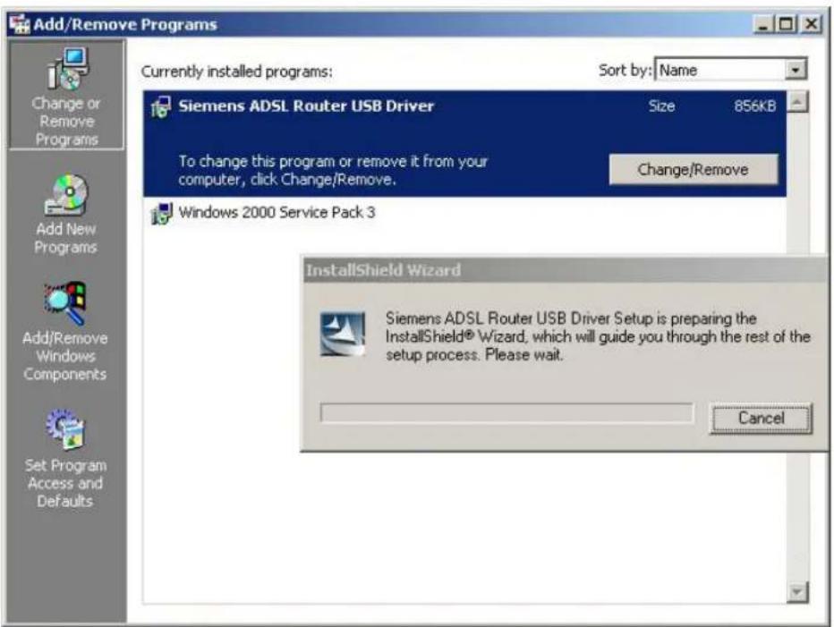
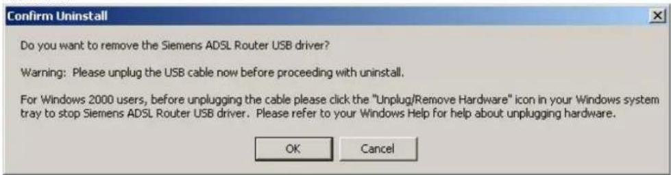
4 A dialog appears to ask you confirm if you want to remove the USB driver or not. Please click Ok.
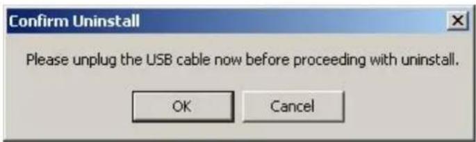
Unplug the USB cable between your device and your PC. Then click OK.
⑤ When the Maintenance Complete screen appears, the USB driver is removed successfully. Click Finish.
For Windows XP
For uninstall the USB driver, there are two ways to do it. Please do as the following:
The first way:
Choose Programs – Siemens Broadband – Uninstall Siemens ADSL Router USB Driver from the Start menu.
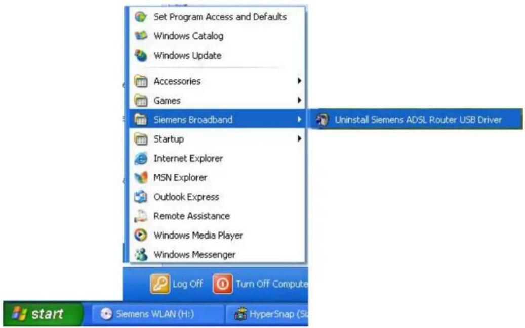
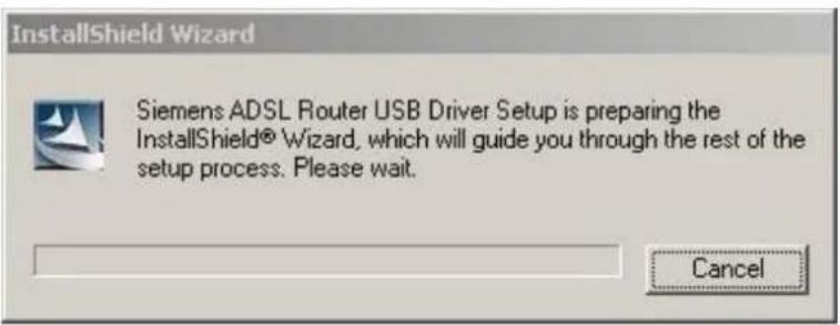
② The InstallShield Wizard dialog will appear.
③ A dialog appears to ask you confirm if you want to remove the USB driver or not. Please click Ok.
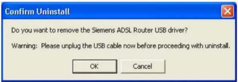
④ Unplug the USB cable between your device and your PC.
⑤ When the Unsafe Removal of Device screen appears, the USB driver is removed successfully. Click OK.
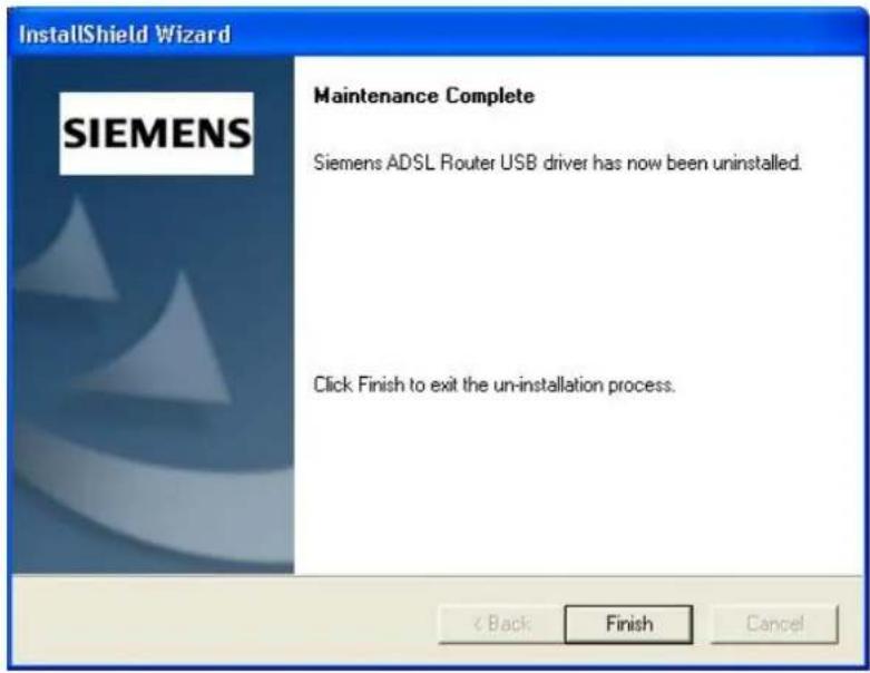
⑥ When the Maintenance Complete screen appears, the USB driver is removed successfully. Click Finish.
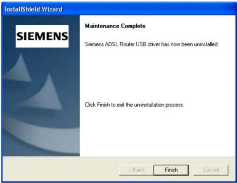
The second way:
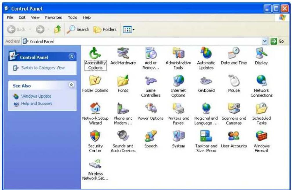
Choose Settings – Control Panel from the Start menu. Choose Add/Remove Programs.
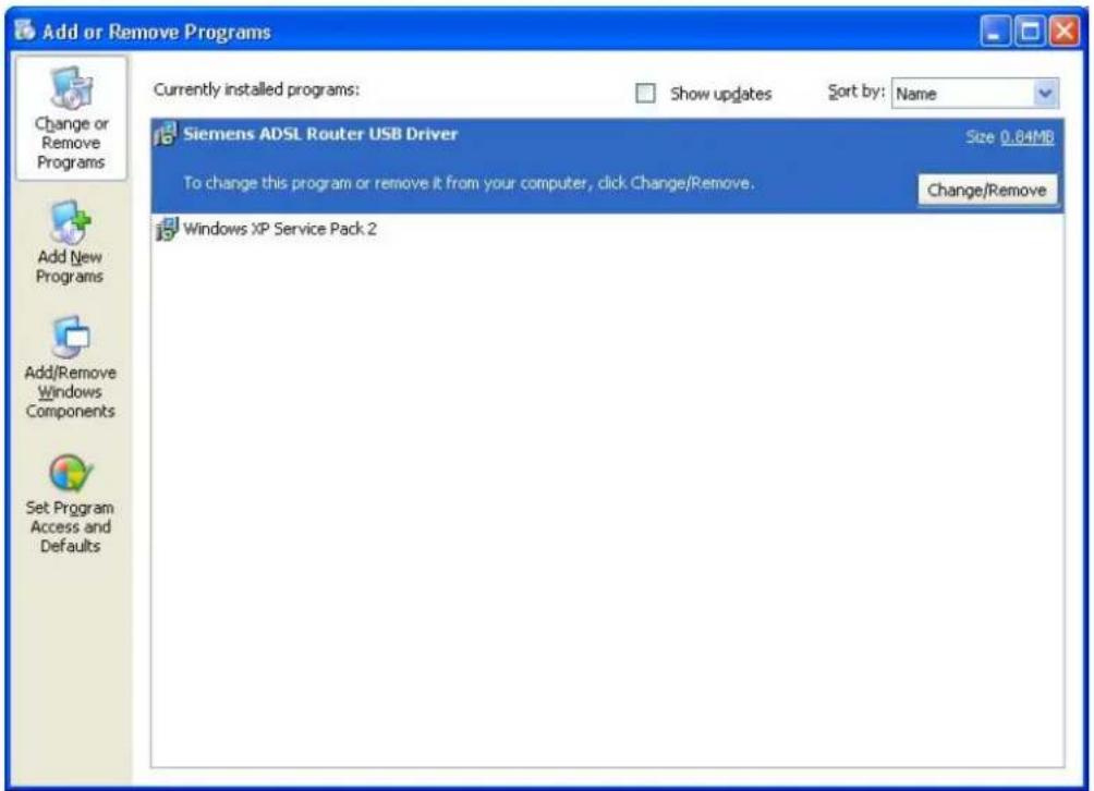
② A dialog appears to ask you choose the program that you want to remove. Please select Siemens ADSL Router USB Driver and click Change/Remove.
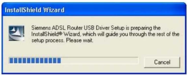
③ The InstallShield Wizard dialog will appear.
4 Unplug the USB cable between your device and your PC. Then click OK.
⑤ When the Maintenance Complete screen appears, the USB driver is removed successfully. Click Finish.
For Windows Vista
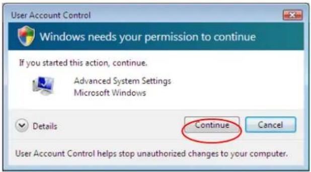
For Vista users, please press Continue whenever a prompted window asking for permission to continue during USB driver uninstallation process (see the figure below for example).
To uninstall the USB driver, there are two ways to do it. Please follow the instructions.
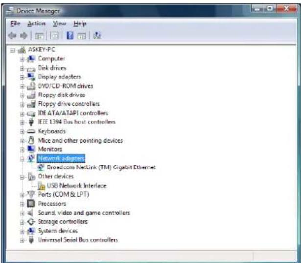
Method One: Remove from Device Manager.
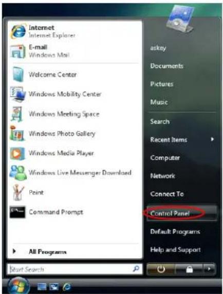
① Choose Start menu, and then select Control Panel.
② Click System and Maintenance.
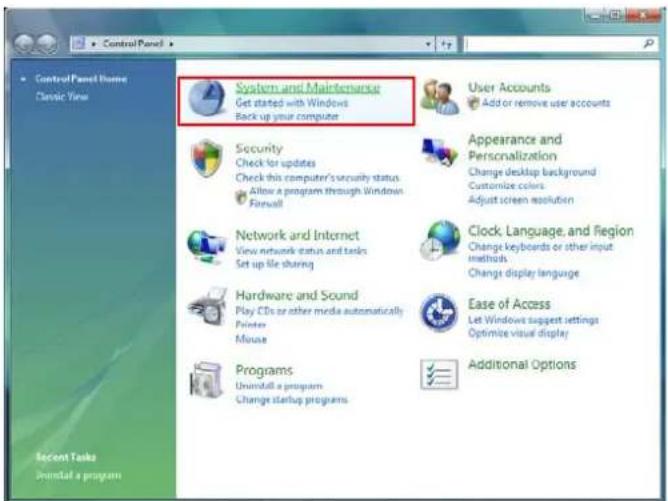
③ Press System.
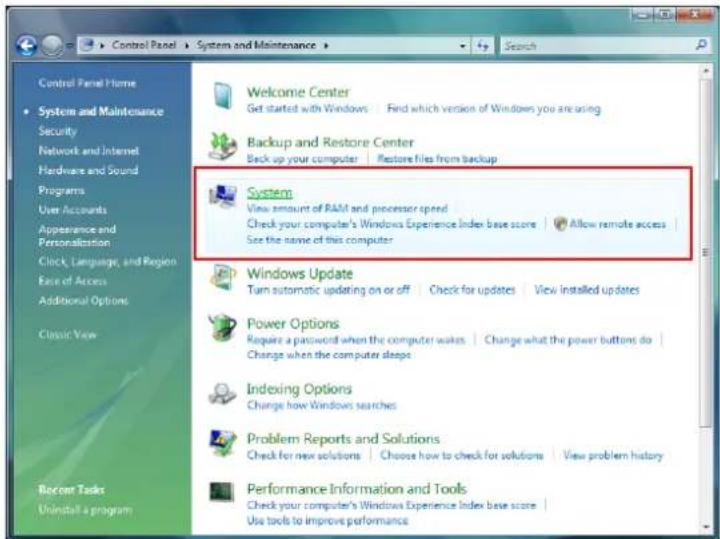
4 Click Device Manager.
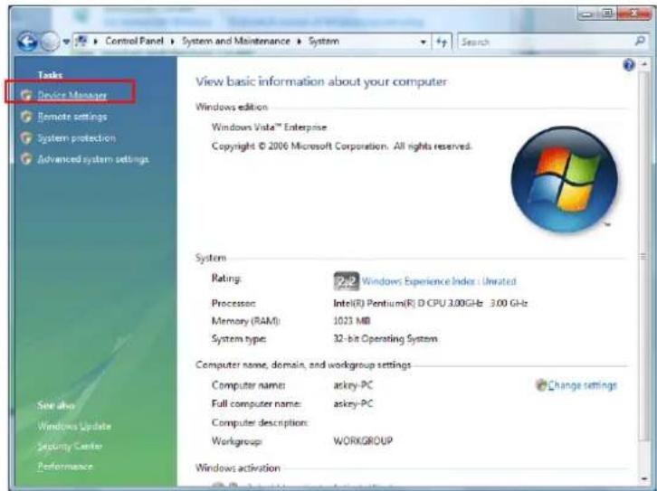
⑤ Right click Askey ADSL Router USB Remote NDIS Device on the Network adapters list, and press Uninstall.
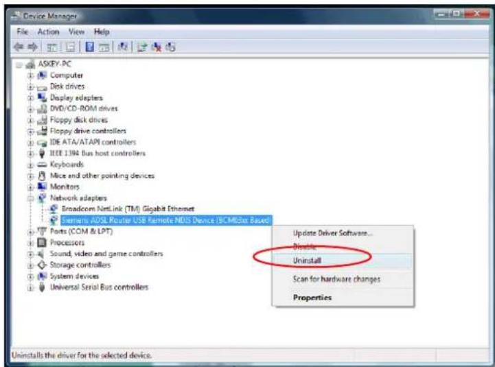
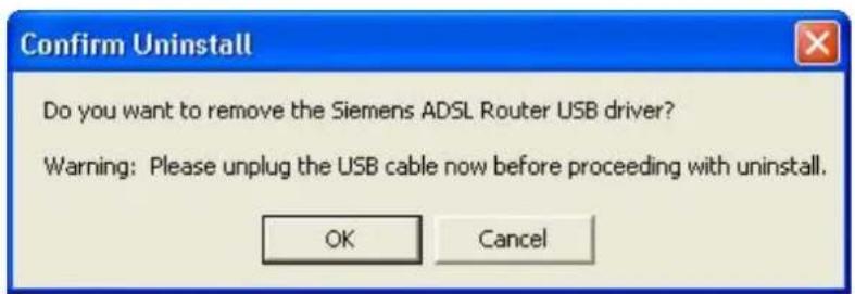
⑥ Click OK when the Confirm Uninstall window appears.
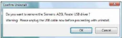
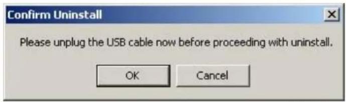
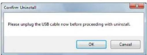
Remember to unplug the USB cable before continue the uninstallation, or you will see the reminder as follows. Unplug and press OK.
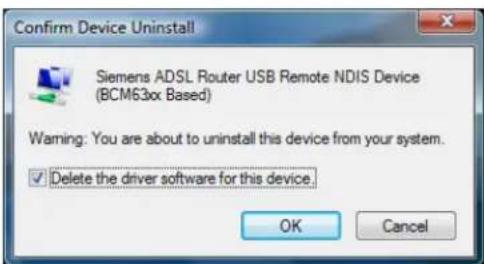
⑦ When the Confirm Device Uninstall screen show up, check Delete the driver software for the device and click OK to continue.
⑧ Wait while the system is uninstalling.
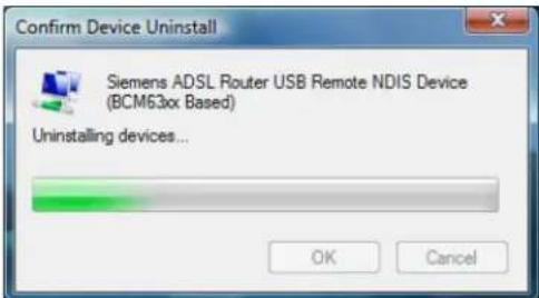
⑨ When the uninstallation is finished, the icon of this router under network adapter list will disappear.
Method Two – uninstall from program list
Note: If your USB driver is installed by UPnP device, you can only use method one (via the Device Manager) to uninstall, because the installed driver will not be shown on the program list.
① Unplug your USB cable between your router and your PC.
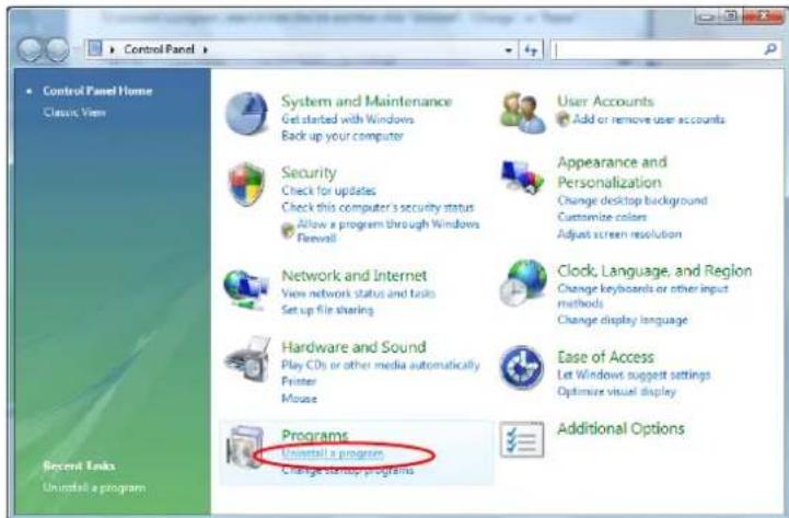
② Choose Start menu, and open Control Panel folder. Click Uninstall a program.
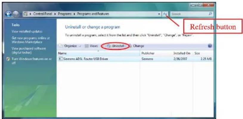
③ If the driver name is not on the list, click Refresh button or F5 to update the information. To remove the driver, select it, and then press Uninstall.
4 Then the system will start to uninstall the USB driver software automatically.
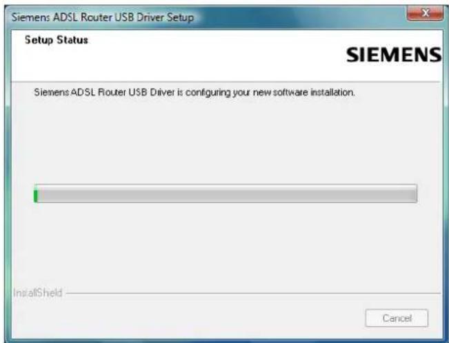
⑤ When Maintenance Complete window shows up, click Finish to exit.
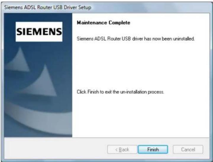
⑥ The USB driver is successfully removed now.
Setting TCP/IP

In order to access the Internet through the router, each host on your network must install/setup TCP/IP. Please follow the steps below for select a network adapter.
For Windows 98
- Click on the Start menu, point to Settings and click on Control Panel.
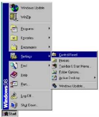
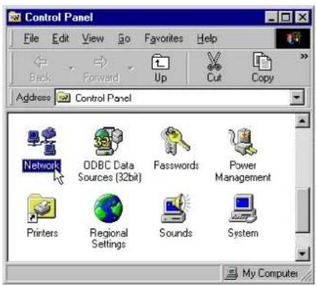
- Double-click the Network icon
- The Network window appears. On the Configuration tab, check out the list of installed network components.
Option 1: If you have no TCP/IP protocol, click Add.
Option 2: If you have TCP/IP protocol, go to Step 6
Your network interface card.
Check out if TCP/IP for your NIC is installed or not.
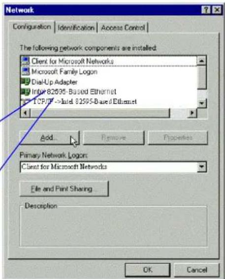
- Highlight Protocol and click Add.
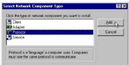
-
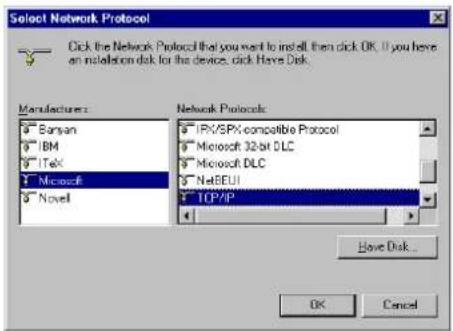
On the left side of the windows, highlight Microsoft and then select TCP/IP on the right side. Then click OK
-
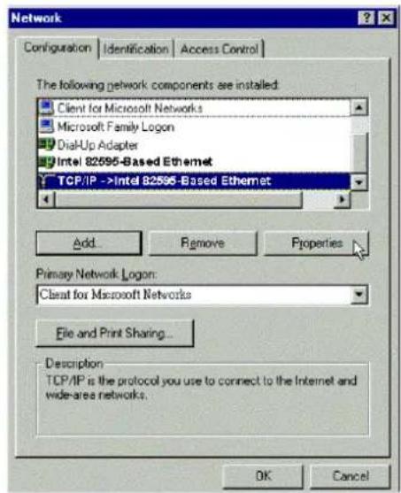
When returning to Network window, highlight TCP/IP protocol for your NIC and click Properties.
-
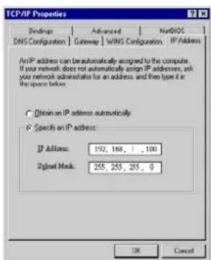
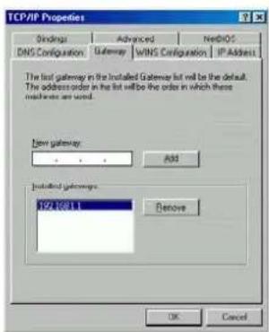
On IP Address tab: Enable Specify an IP address option. Enter the IP Address: 192.168.1.x (x is between 2 and 254) and Subnet Mask: 255.255.255.0 as in figure below. On Gateway tab: Add a gateway IP address: 192.168.1.1 and click OK
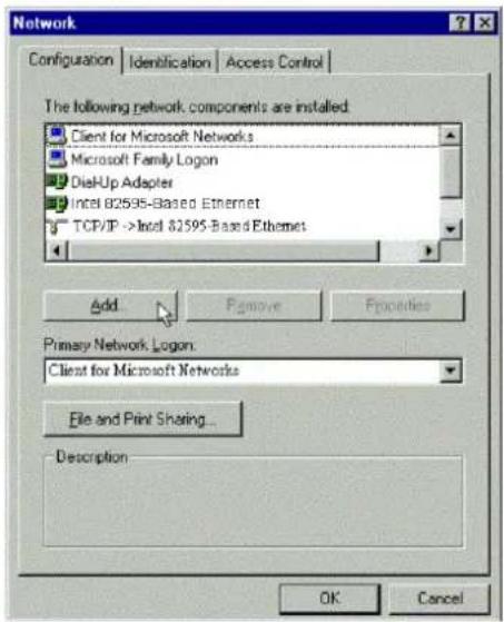
- When returning to Network window, click OK
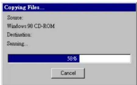
- Wait for Windows copying files.
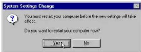
- When prompted with System Settings Change dialog box, click Yes to restart your computer.
For Windows ME
- Click on the Start menu, point to Settings and click on Control Panel.
- Double-click the Network icon.
-
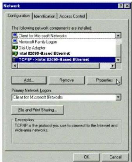
The Network window appears. On the Configuration tab, check out the list of installed network components. Option 1: If you have no TCP/IP protocol, click Add. Option 2: If you have TCP/IP protocol, go to Step 6.
-
Highlight Protocol and click Add.
-
On the left side of the windows, highlight Microsoft and then select TCP/IP on the right side. Then click OK.
-
While returning to Network window, highlight TCP/IP protocol for your NIC and click Properties.
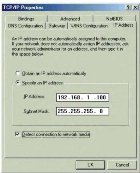
- On the IP Address tab, select Specify an IP address. Enter the IP address: 192.168.1.x (x is between 2 and 254), Subnet Mask: 255.255.255.0 and Default gateway: 192.168.1.1. Then click OK.
-
While returning to the Network window, click OK.
-
Wait for Windows copying files.
- When prompted with the System Settings Change dialog box, click Yes to restart your computer.
For Windows NT
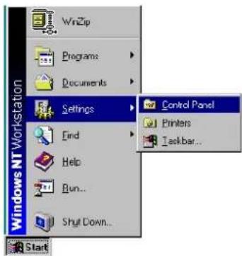
- Click Start, point to Settings, and then click Control Panel.
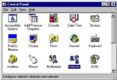
- Double-click the Network icon.
- The Network window appears. On the Protocols tab, check out the list of installed network components. Option 1: If you have no TCP/IP Protocol, click Add. Option 2: If you have TCP/IP Protocol installed, go to Step 7.
- Highlight TCP/IP Protocol and click OK.
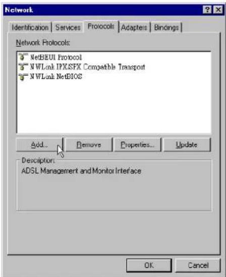
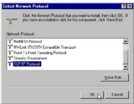
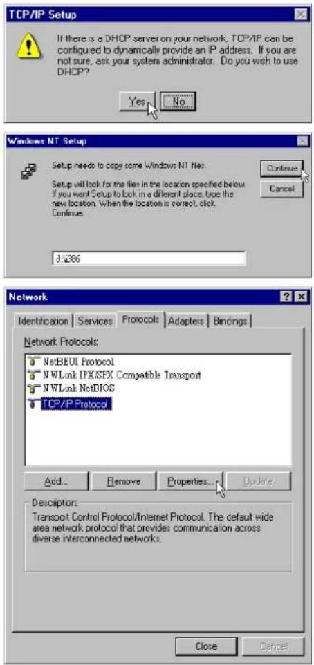
- Click Yes to use DHCP.
- Insert the Windows NT CD into your CD-ROM drive and type the location of the CD. Then click Continue.
-
Returning to the Network window, you will find the TCP/IP Protocol among the list. Select TCP/IP Protocol and click Properties.
-
Enable Specify an IP address option. Enter the IP Address: 192.168.1.x (x is between 2 and 254) and Subnet Mask: 255.255.255.0 and Default Gateway: 192.168.1.1 as in figure below.
![Microsoft TCP/IP Properties IP Address DNS WINS Address Routing An IP address can be automatically assigned to this network card by a DHCP server. If your network does not have a DHCP server, ask your network administrator for an address, and then type it in the space below. Adapter: [1] Intel 82595-Based Ethernet Obtain an IP address from a DHCP server Specify an IP address IP Address: 192, 168, 1 , 100 Sujet Mask: 255, 255, 255, 0 Default Gateway: 192, 168, 1 , 1 Advanced... OK Cancel Apply](/content/2026/05/1021346/images/4d81442ad56ec2052e5d211b410c873674017f087423c34865ff8c2b53d2e44f.jpg)
- When returning to Network window, click Close.
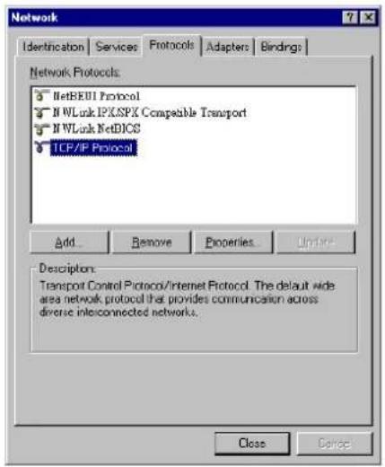
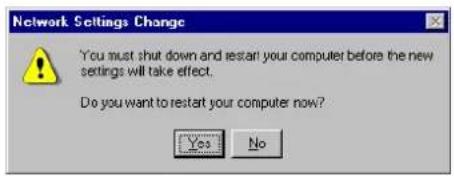
- When prompted with Network Settings Change dialog box, click Yes to restart your computer.
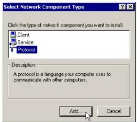
For Windows 2000
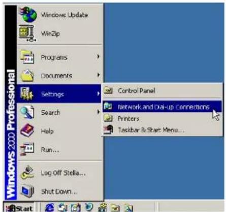
- From the Start menu, point to Settings and then click Network and Dial-up Connections.
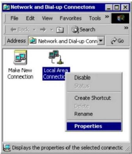
- Right-click the Local Area Connection icon and then click Properties.
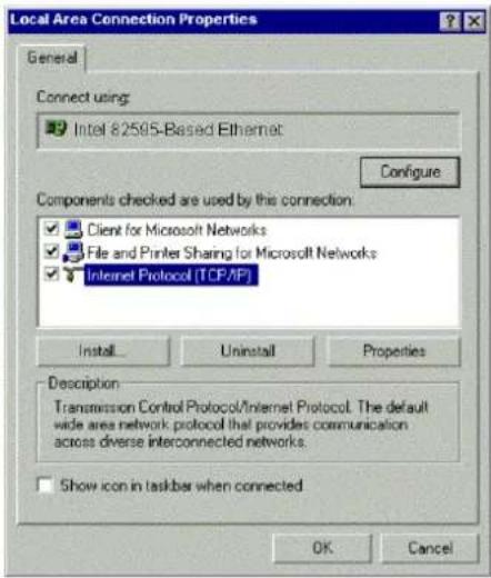
- On the General tab, check out the list of installed network components. Option 1: If you have no TCP/IP Protocol, click Install. Option 2: If you have TCP/IP Protocol, go to Step 6.
-
Highlight Protocol and then click Add.
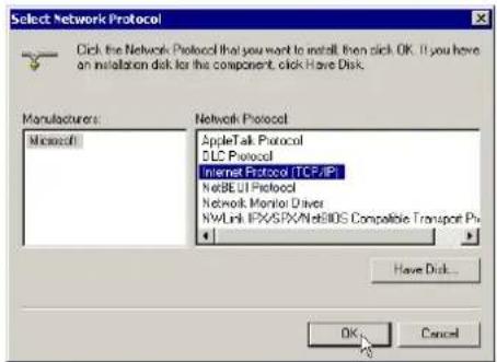
-
Click Internet Protocol (TCP/IP) and then click OK.
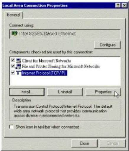
-
When returning to Local Area Connection Properties window, highlight Internet Protocol (TCP/IP) and then click Properties.
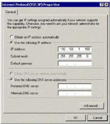
-
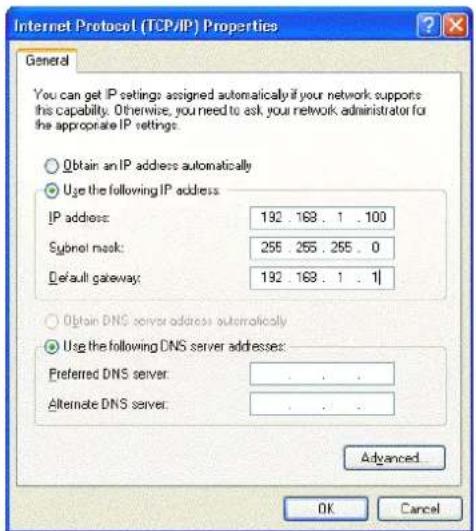
Under the General tab, enable Use the following IP Address. Enter the IP address: 192.168.1.x (x is between 2 and 254), Subnet Mask: 255.255.255.0 and Default gateway: 192.168.1.1. Then click OK.
For Windows XP
From the Start menu, point to Control Panel and then click Network and Internet Connections.
Click Network Connection and then click Properties.
Click Network Connection and then click Properties.3.On the General tab, check out the list of installed network components.
Option 1: If you have no TCP/IP
Protocol, click Install.
Option 2: If you have TCP/IP Protocol, go to Step 6.
Highlight Protocol and then click Add.
Click Internet Protocol(TCP/IP) and then click OK.
On the Local Area Connection Properties window, highlight Internet Protocol (TCP/IP) and then click Properties.
![Local Area Connection Properties General Authentication Advanced Connect using: Intel 82595-Based Ethernet Configure... This connection uses the following items: Client for Microsoft Networks File and Printer Sharing for Microsoft Networks QoS Packet Scheduler Internet Protocol [TCP/IP] Install... Uninstall Properties Description Transmission Control Protocol/Internet Protocol. The default wide area network protocol that provides communication across diverse interconnected networks. Show icon in notification area when connected OK Cancel](/content/2026/05/1021346/images/f21f57098f3b08040f6d5c0efaa266c552b8c1ba760192c051f34968ab3ee339.jpg)
Under the General tab, enable Use the following IP address. Enter the IP address: 192.168.1.x (x is between 2 and 254), Subnet Mask: 255.255.255.0 and Default gateway: 192.168.1.1. Then click Ok.
For Windows Vista
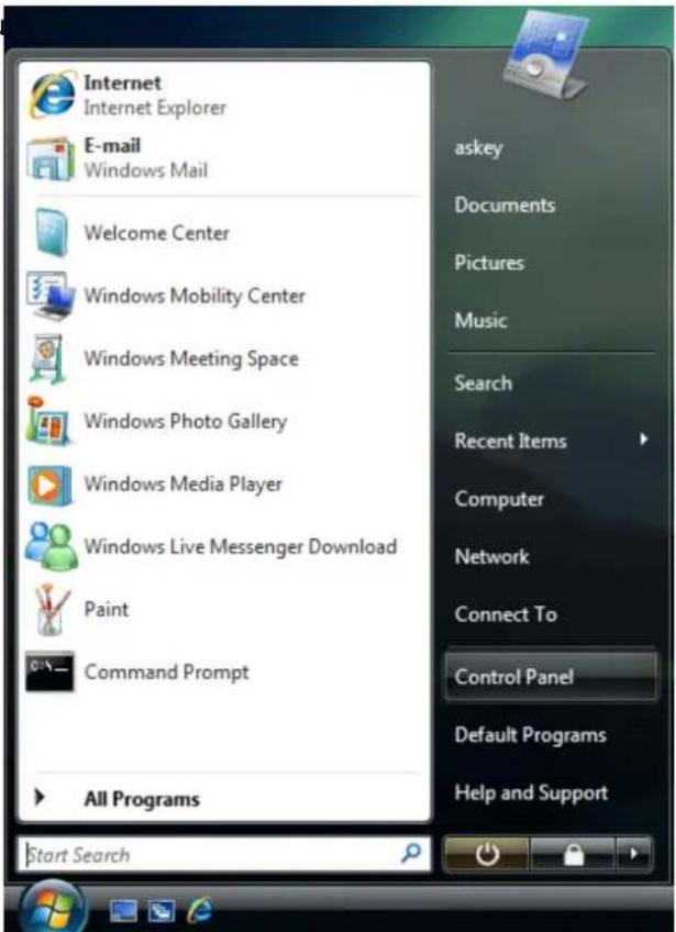
- Open the Start menu point to Control Panel and click it.
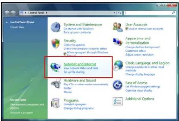
- Click Network and Internet.
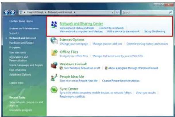
- Select Network and Sharing Center.
- Click Manage Network Connection on the left side.
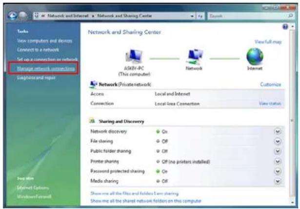
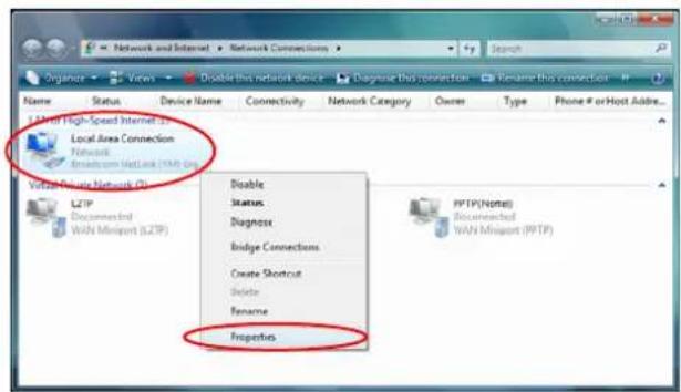
- Right click Local Area Connection and select Properties.
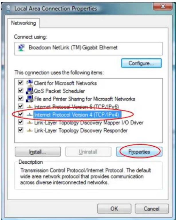
- On the Networking tab you will find Internet Protocol Version 6 and Version 4. Contact your ISP to confirm which one will be used. (We take TCP/IPv4 for example here.)
Select Internet Protocol Version 4 (TCP/IPv4) and press Properties.
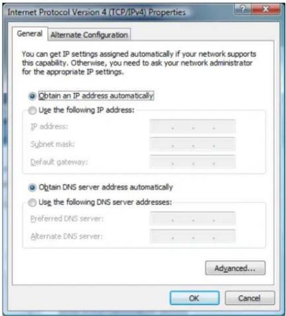
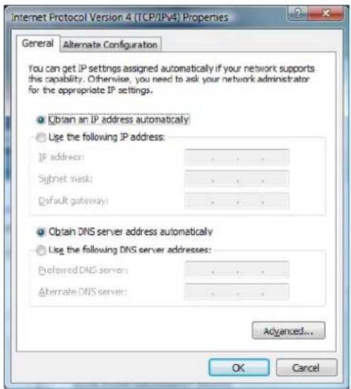
- Under the General tab, select Obtain an IP address automatically, and Obtain DNS server address automatically. Then click Ok to exit.
Configure PC to get IP address from DHCP
If your ADSL Router operates as a DHCP server for the client PCs on the LAN, you should configure the client PCs to obtain a dynamic IP address. Please follow the previous section to install TCP/IP component. Only that you do not need to specify an IP address when configuring TCP/IP properties.
The following section describe the procedures for CPEs to get IP address:
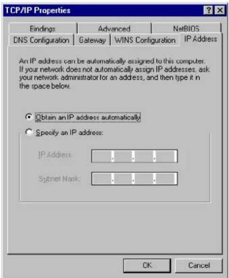
For Windows 98
On the IP Address tab, select Obtain an IP address automatically. Then click OK.
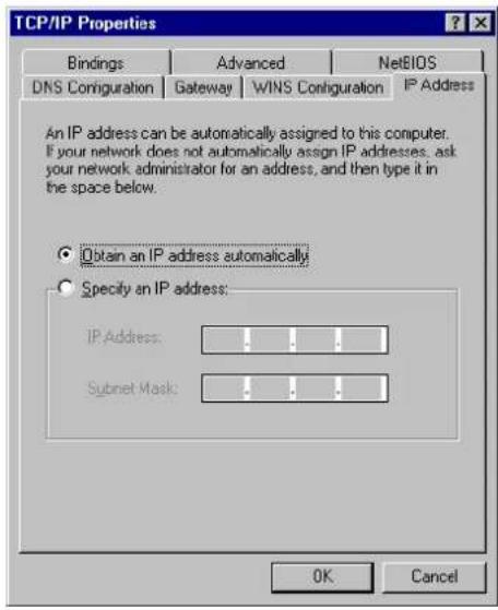
For Windows ME
On the IP Address tab, select Obtain an IP address automatically. Then click OK.
For Windows NT
On the IP Address tab, click on the drop-down arrow of Adapter to select required adapter. Enable Obtain an IP address from a DHCP server and then click OK..
![Microsoft TCP/IP Properties IP Address DNS WINS Address Routing An IP address can be automatically assigned to this network card by a DHCP server. If your network does not have a DHCP server, ask your network administrator for an address, and then type it in the space below. Adapter [1] Intel 82695-Based Ethernet Obtain an IP address from a DHCP server Specify an IP address IP Address: Signet Mask: Default Gateway: Advanced... OK Cancel Apply](/content/2026/05/1021346/images/991f1adcae56e7c383a8d642e7b990e92f13c8e31484bdb1e5ebc7775913df7f.jpg)
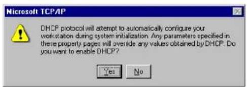
When prompted with the message below, click Yes to continue.
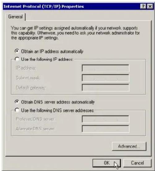
For Windows 2000
Enable Obtain an IP address automatically and then click OK.
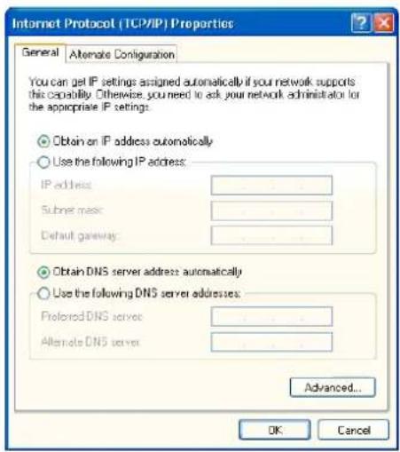
For Windows XP
On the IP Address tab, select Obtain an IP address automatically. Then click OK.
Windows Vista
On the IP Address tab, select Obtain an IP address automatically. Then click OK.
Renew IP Address on Client PC
There is a chance that your PC does not renew its IP address after the ADSL Router is on line and the PC cannot access the Internet. Please follow the procedures below to renew PC's IP address.
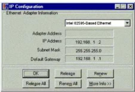
For Windows 98ME
- Select Run from the Start menu.
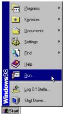
- Type winipcfg in the dialog box and the click OK.
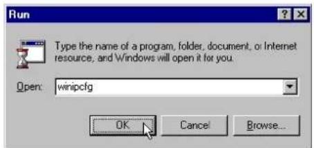
- When the figure below appears, click Release and then Renew to get an IP address.
For Windows NT
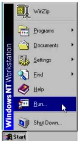
- Select Run from the Start menu.
-
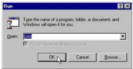
Select Run from the Start menu.
-
Type cmd in the dialog box and the click OK.
-
Type ipconfig at prompt. Then you will see the IP information from DHCP server.
-
If you want to get a new IP address, type ipconfig /release to release the previous IP address and then type ipconfig /renew to get a new one.
For Windows 2000
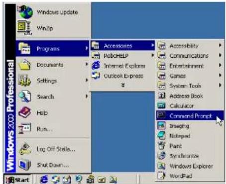
- From the Start menu, point to Programs, Accessories and then click Command Prompt.
- Type ipconfig at prompt. Then you will see the IP information from DHCP server.
- If you want to get a new IP address, type ipconfig /release to release the previous IP address and then type ipconfig /renew to get a new one.
For Windows XP
- Type ipconfig at prompt. Then you will see the IP information from DHCP server.
- From the Start menu, point to Programs, Accessories and then click Command Prompt.
- Type ipconfig at prompt. Then you will see the IP information from DHCP server.
- If you want to get a new IP address, type ipconfig /release to release the previous IP address and then type ipconfig /renew to get a new one.
For Windows Vista
- Open the Start menu, and type cmd in the text box then click OK.
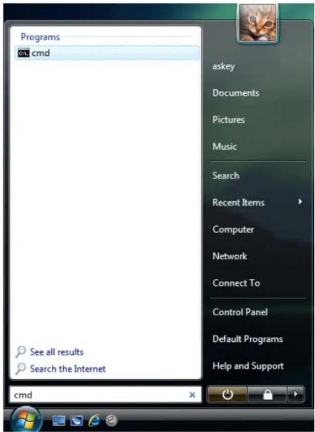
- The command prompt window will appear.
![Microsoft Windows [Version 6.0.6080] Copyright (c) 2006 Microsoft Corporation. All rights reserved. C:\Windows\system32>](/content/2026/05/1021346/images/a6a31809e29c2d75dcd784685aab88bc9e70349b2d56539ecdcbee80fb996a7a.jpg)
- Type ipconfig at the command window and press Enter to view the computer's IP information from DHCP server.
![Microsoft Windows [Version 6.0.6000] Copyright (c) 2006 Microsoft Corporation. All rights reserved. C:\Windows\system32>ipeconfig Windows IP Configuration Ethernet adapter Local Area Connection: Connection-specific DNS Suffix . : asky.sevd.tv Link-local IPv6 Address . . . . . : fe80::6106:a982:1461:b313%8 IPv4 Address . . . . . . . . . . . : 10.11.95.22 Subnet Mask . . . . . . . . . . : 255.255.255.0 Default Gateway . . . . . . . . . : 10.11.95.1 C:\Windows\system32>](/content/2026/05/1021346/images/3bae1a74014c5b030e96339b9fb1167798c8abfa1b7d0ddfe6081b9650dce97b.jpg)
- If the computer is holding a current IP address, type ipconfig /release to let go of the address, then type ipconfig /renew to obtain a new one.
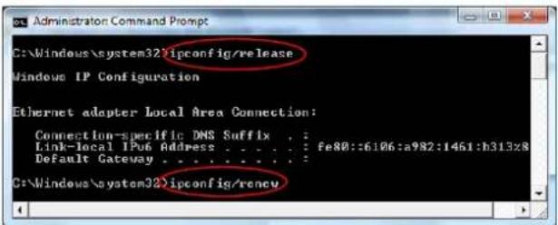
Note:
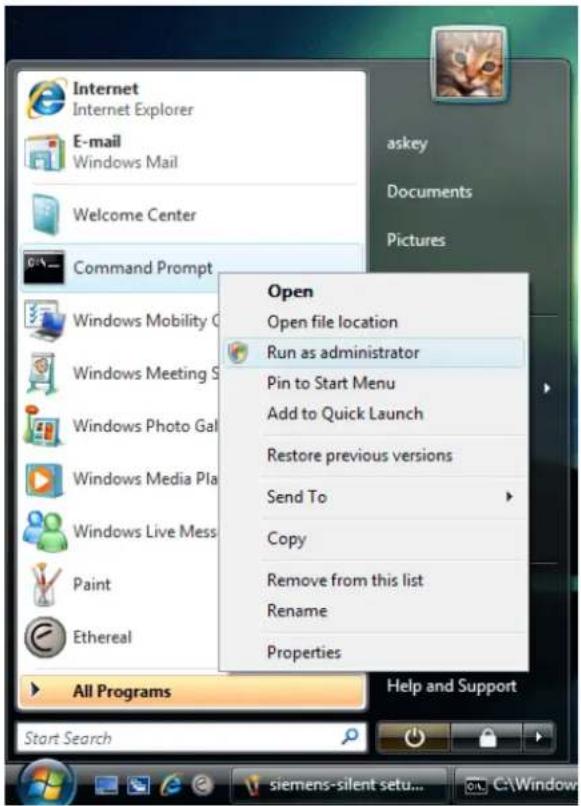
If you cannot release the IP address successfully and see the message "The requested operation requires elevation," please go to the Start menu and right click Command Prompt, then set Run as administrator.
Press Continue when a dialog asking for permission to continue prompts.
After then, repeat the above instruction to release and renew the IP address.
Chapter 3: Connecting and Accessing Internet

This chapter is to help you accessing into Internet with a quick and convenient way. If you need more detailed information for web configuration, please get into the next chapter for the advanced configuration.
Prior to configuring the ADSL Router, you must decide whether to configure the ADSL Router as a bridge or as a router. This chapter presents some deployment examples for your reference. Each mode includes its general configure procedures. For more detailed information about web configuration, refer to "Web Configuration".
□ PPP over ATM (PPPoA)
□ PPPoA IP Extension
□ PPP over Ethernet (PPPoE)
□ PPPoE IP Extension
☐ Numbered IP over ATM (IPoA)
☐ Numbered IP over ATM (IPoA)+NAT
□ Unnumbered IP over ATM (IPoA)
□ Unnumbered IP over ATM (IPoA)+NAT
□ Bridging
For making sure that you can connect the ADSL to your computer well and get into Internet successfully, please make sure the following first.
☐ Make sure you have installed a network interface card into your computer.
☐ Make sure the connection between the ADSL and your computer is OK.
☐ Check to see the TCP/IP protocol and set the IP address as “Auto Get IP Address”.
When you are sure all above is Ok, you can open the Browser and type in "192.168.1.1" and start to do the web configuration with different connection modes.
This chapter is going to introduce the function of each connection mode and tell you the basic configuring steps that you have to do. If you did not follow the configuring steps for using these connection modes, you might get some connection problems and cannot connect to Internet well.
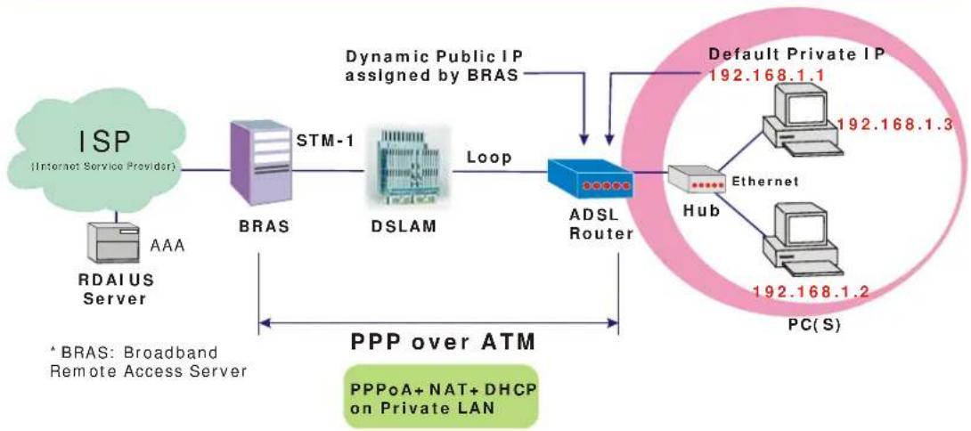
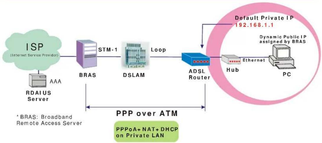
PPP over ATM (PPPoA) Mode
flowchart
graph LR
    A["ISP (Internet Service Provider)"] --> B["BRAS"]
    B --> C["STM-1"]
    C --> D["DSLAM"]
    D --> E["Loop"]
    E --> F["ADSL Router"]
    F --> G["Default Private IP 192.168.1.1"]
    F --> H["Ethernet 192.168.1.3"]
    F --> I["PC(S) 192.168.1.2"]
    J["RDAIUS Server"] --> K["AAA"]
    L["*BRAS: Broadband Remote Access Server"] --> M["PPP over ATM"]
    M --> N["PPPoA+ NAT+ DHCP on Private LAN"]
    style A fill:#d4edda,stroke:#333
    style B fill:#d4edda,stroke:#333
    style C fill:#d4edda,stroke:#333
    style D fill:#d4edda,stroke:#333
    style E fill:#d4edda,stroke:#333
    style F fill:#d4edda,stroke:#333
    style G fill:#d4edda,stroke:#333
    style H fill:#d4edda,stroke:#333
    style I fill:#d4edda,stroke:#333
    style J fill:#d4edda,stroke:#333
    style K fill:#d4edda,stroke:#333
    style L fill:#d4edda,stroke:#333
    style M fill:#d4edda,stroke:#333
    style N fill:#d4edda,stroke:#333
Description:
In this deployment environment, the PPPoA session is between the ADSL WAN interface and BRAS. The ADSL Router gets a public IP address from BRAS when connecting to DSLAM. The multiple client PCs will get private IP address from the DHCP server enabled on private LAN. The enabled NAT mechanism will translate the IP information for clients to access the Internet.
Configuration:
- Start up your browser and type 192.168.1.1 as the address to enter this ADSL web-based manager.
- Go to Quick Start -Quick Setup. Uncheck Auto Scan Internet Connection (PVC). Type in the VCI and VPI value. Then click the Next button. eg:
VPI-0
VCI-38 - On the Configure Internet Connection -Connection Type page, select the PPP over ATM (PPPoA) then click the Next button.
- In the WAN IP Settings page, select Obtain an IP address automatically and check Enable NAT box. Click Next.
- In the PPP Username and Password page, enter the PPP username and password that you got from your ISP. Select Dial on Demand and type in the number for inactivity timeout. The default is 20. Or select Always on. Then click Next.
- In the Configure LAN side Settings page, type in the IP address and subnet mask for your LAN. Check DHCP Server on box. And type in the start and end points. Then type in the leased time that you want. And click Next. eg:
Primary IP address:192.168.1.1
Subnet Mask:255.255.255.0
Start IP Address:192.168.1.2
End IP Address: 192.168.1.254 - Check the network information. Make sure the settings match the settings provided by ISP. Click Finish.
PPP over ATM (PPPoA) IP Extension Mode
flowchart
graph LR
    A["ISP (Internet Service Provider)"] --> B["BRAS"]
    B --> C["STM-1"]
    C --> D["DSLAM"]
    D --> E["Loop"]
    E --> F["ADSL Router"]
    F --> G["Default Private IP 192.168.1.1"]
    G --> H["PC"]
    I["RDAIUS Server"] --> B
    J["* BRAS: Broadband Remote Access Server"] --> F
    K["PPP over ATM PPPoA+ NAT+ DHCP on Private LAN"] --> F
    L["Ethernet"] --> F
    M["Dynamic Public IP assigned by BRAS"] --> G
Description:
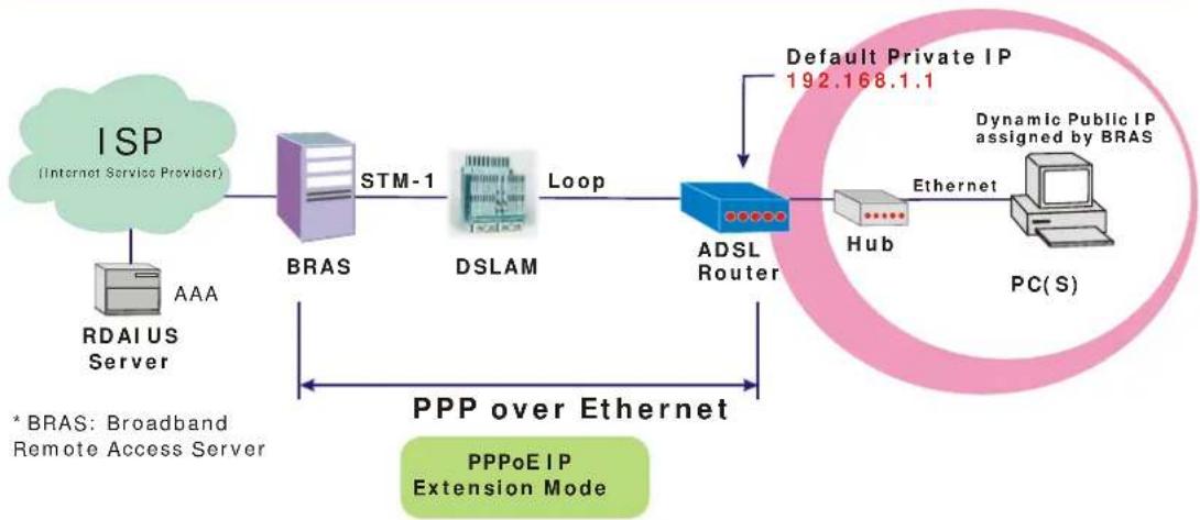
In this deployment environment, the PPPoA session is between the ADSL WAN interface and BRAS. The ADSL Router acts as a bridge and gets a public IP address from BRAS for your computer. And only the one that got the public IP address is allowed to access into Internet. Moreover, no NAT translation will be done at this case.
Configuration:
- Start up your browser and type 192.168.1.1 as the address to enter this ADSL web-based manager.
- Go to Advanced - Internet - Connections. And click Add.
- Type in the VCI and VPI value. Then click the Next button. eg: VPI - 0 VCI - 38
- On the Configure Internet Connection -Connection Type page, select the PPP over ATM (PPPoA) then click the Next button.
- In the WAN IP Settings page, select Obtain an IP address automatically, uncheck Enable NAT box and check PPP IP extension then click Next.
- In the PPP Username and Password page, enter the PPP username and password that you got from your ISP. Select Dial on Demand and type in the number for inactivity timeout. The default is 20. Or select Always on. Then click Next.
- In the Configure LAN side Settings page, type in the IP address and subnet mask for your LAN. And click Next. eg: Primary IP address:192.168.1.1 Subnet Mask:255.255.255.0
- Check the network information. Make sure the settings match the settings provided by ISP. Click Finish.
PPP over Ethernet (PPPoE) Mode
flowchart
graph LR
    A["ISP (Internet Service Provider)"] --> B["BRAS"]
    B --> C["STM-1"]
    C --> D["DSLAM"]
    D --> E["Loop"]
    E --> F["ADSL Router"]
    F --> G["Default Private IP 192.168.1.1"]
    F --> H["Hub"]
    H --> I["Ethernet"]
    I --> J["PC(S)"]
    K["RDAIUS Server"] --> L["AAA"]
    M["*BRAS: Broadband Remote Access Server"] --> N["PPP over Ethernet"]
    O["PPPoE+ NAT+ DHCP on Private LAN"] --> P["Loop"]
    Q["Dynamic Public IP assigned by BRAS"] --> E
Description:
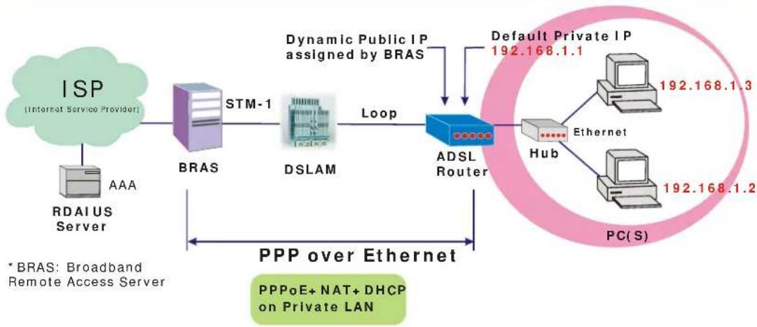
In this deployment environment, the PPPoE session is between the ADSL WAN interface and BRAS. The ADSL Router gets a public IP address from BRAS when connecting to DSLAM. The multiple client PCs will get private IP address from the DHCP server enabled on private LAN. The enabled NAT mechanism will translate the IP information for clients to access the Internet.
Configuration:
- Start up your browser and type 192.168.1.1 as the address to enter this ADSL web-based manager.
- Go to Quick Start -Quick Setup. Uncheck Auto Scan Internet Connection (PVC). Type in the VCI and VPI value. Then click the Next button. eg:
VPI-0 VCI-39 - On the Configure Internet Connection -Connection Type page, select the PPP over Ethernet (PPPoE) then click the Next button.
- In the WAN IP Settings page, select Obtain an IP address automatically and check Enable NAT box. Click Next.
- In the PPP Username and Password page, enter the PPP username and password that you got from your ISP. Select Dial on Demand and type in the number for inactivity timeout. The default is 20. Or select Always on. Then click Next.
- In the Configure LAN side Settings page, type in the IP address and subnet mask for your LAN. Check DHCP Server on box. And type in the start and end points. Then type in the leased time that you want. And click Next. eg:
Primary IP address:192.168.1.1 Subnet Mask:255.255.255.0 Start IP Address:192.168.1.2 End IP Address: 192.168.1.254 - Check the network information. Make sure the settings match the settings provided by ISP. Click Finish.
PPP over Ethernet (PPPoE) IP Extension Mode
flowchart
graph LR
    A["ISP (Internet Service Provider)"] --> B["BRAS"]
    B --> C["STM-1"]
    C --> D["DSLAM"]
    D --> E["Loop"]
    E --> F["ADSL Router"]
    F --> G["Hub"]
    G --> H["Ethernet"]
    H --> I["PC(S)"]
    I --> J["Dynamic Public IP assigned by BRAS"]
    K["RDAI US Server"] --> L["AAA"]
    M["Default Private IP 192.168.1.1"] --> F
    N["* BRAS: Broadband Remote Access Server"] --> F
    O["PPP over Ethernet"] --> P["PPPoEIP Extension Mode"]
Description:
In this deployment environment, the PPPoE session is between the ADSL WAN interface and BRAS. The ADSL Router acts as a bridge and gets a public IP address from BRAS for your computer. And only the one that got the public IP address is allowed to access into Internet. The real IP that you got is acquired from ISP. Moreover, no NAT translation will be done at this case.
Configuration:
- Start up your browser and type 192.168.1.1 as the address to enter this ADSL web-based manager.
- Go to Advanced - Internet - Connections. And click Add.
- Type in the VCI and VPI value. Then click the Next button. eg: VPI - 0 VCI - 39
- On the Configure Internet Connection -Connection Type page, select the PPP over Ethernet (PPPoE) then click the Next button.
- In the WAN IP Settings page, select Obtain an IP address automatically, uncheck Enable NAT box and check PPP IP extension then click Next.
- In the PPP Username and Password page, enter the PPP username and password that you got from your ISP. Select Dial on Demand and type in the number for inactivity timeout. The default is 20. Or select Always on. Then click Next.
- In the Configure LAN side Settings page, type in the IP address and subnet mask for your LAN. And click Next. eg: Primary IP address:192.168.1.1 Subnet Mask:255.255.255.0
- Check the network information. Make sure the settings match the settings provided by ISP. Click Finish.
Numbered IP over ATM (IPoA)
flowchart
graph LR
    A["ISP (Internet Service Provider)"] --> B["BRAS"]
    B --> C["DSLAM"]
    C --> D["ADSL Router"]
    D --> E["Hub"]
    E --> F["S/W"]
    E --> G["PC(S)"]
    H["RDAIUS Server"] --> B
    I["Default Private IP 192.168.1.1"] --> D
    J["*BRAS: Broadband Remote Access Server"] --> B
    K["IP over ATM Public IP Pre-assigned by ISP"] --> D
Description:
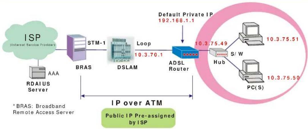
If you apply for multiple IP addresses from your ISP, you can assign these public IP addresses to the ADSL Router and public server, e.g., Web or FTP server. Typically the first IP is network address, the second is used as router IP address and the last one is subnet broadcasting. Other remaining IP addresses can be assigned to PCs on the LAN.
The following example uses the LAN IP address ranging from 10.3.75.49 to 10.3.75.54 and the subnet mask for LAN is 255.255.255.248. The WAN address is 10.3.70.1, and the subnet mask for WAN is 255.255.255.252.
Configuration:
- Start up your browser and type 192.168.1.1 as the address to enter this ADSL web-based manager.
- Go to Quick Start -Quick Setup. Uncheck Auto Scan Internet Connection (PVC). Type in the VCI and VPI value. Then click the Next button.
VPI-0
VCI-32 - On the Configure Internet Connection -Connection Type page, select the IP over ATM (IPoA) then click the Next button.
- In the WAN IP Settings page, select Use the following IP address and type in the IP address, subnet mask and gateway that you got from ISP. Then, select Use the following DNS Server Address. Type in the Primary DNS server and Secondary DNS server. Uncheck Enable NAT. Click Next for next page.
WAN IP Address: 10.3.70.1
WAN Subnet Mask: 255.255.255.252
Primary DNS server: 168.95.1.1
Secondary DNS server: 168.95.192.1 - In the Configure LAN side Settings page, type in the IP address and subnet mask for your LAN.
Primary IP Address: 192.168.1.1
Subnet mask: 255.255.255.0
Start IP Address: 192.168.1.2
End IP Address: 192.168.1.254 -
Check Configure the second IP Address and Subnet Mask for LAN Interface and type in the second IP address and subnet mask. Then click Next.
Secondary IP Address: 10.3.75.49
Subnet mask: 255.255.255.248 -
Check the network information. Make sure the settings match the settings provided by ISP. Click Finish.
- Set TCP/IP for your computer. Specify an IP Address, subnet mask and set default gateway. eg: IP Address: 10.3.75.51
Subnet Mask: 255.255.255.248
Gateway: 10.3.75.49 - Now the router is well configured. You can access into Internet.
Numbered IP over ATM (IPoA) + NAT
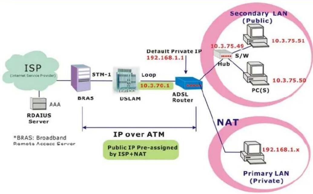
flowchart
graph TD
    A["ISP (Internet Service Provider)"] --> B["BRAS"]
    B --> C["DSLAM"]
    C --> D["ADSL Router"]
    D --> E["Secondary LAN (Public)"]
    D --> F["Primary LAN (Private)"]
    G["RDAIUS Server"] --> H["BRAS"]
    H --> I["DSLAM"]
    I --> J["Default Private IP 192.168.1.1"]
    K["*BRAS: Broadband Remote Access Server"] --> L["IP over ATM"]
    L --> M["Public IP Pre-assigned by ISP+NAT"]
    N["Loop 10.3.70.1"] --> D
    O["Hub 10.3.75.49"] --> P["S/W"]
    P --> Q["PC(S)"]
    R["NAT 192.168.1.x"] --> S["Primary LAN (Private)"]
Description:
In this deployment environment, we make up a private IP network of 192.168.1.1. NAT function is enabled (on ADSL Router or use another NAT box connected to hub) to support multiple clients to access the Router and some public servers (WWW, FTP).
If you apply for multiple IP addresses from your ISP, you can assign these public IP addresses to the ADSL Router and public server, e.g., Web or FTP server. Typically the first IP is network address, the second is used as router IP address and the last one is subnet broadcasting. Other remaining IP addresses can be assigned to PCs on the LAN.
The following example uses the LAN IP address ranging from 10.3.75.49 to 10.3.75.54 and the subnet mask for LAN is 255.255.255.248. The WAN address is 10.3.70.1, and the subnet mask for WAN is 255.255.255.252.
Configuration:
- Start up your browser and type 192.168.1.1 as the address to enter this ADSL web-based manager.
- Go to Quick Start -Quick Setup. Uncheck Auto Scan Internet Connection (PVC). Type in the VCI and VPI value. Then click the Next button.
VPI-0 VCI-32 - On the Configure Internet Connection -Connection Type page, select the IP over ATM (IPoA) then click the Next button.
- In the WAN IP Settings page, select Use the following IP address and type in the IP address, subnet mask and gateway that you got from ISP. Then, select Use the following DNS Server Address. Type in the Primary DNS server and Secondary DNS server.
WAN IP Address: 10.3.70.1 WAN Subnet Mask: 255.255.255.252 Primary DNS server: 168.95.1.1 Secondary DNS server: 168.95.192.1 - Check the Enable NAT box. And click Next.
- In the Configure LAN side Settings page, type in the IP address and subnet mask for your
LAN.
Primary IP Address: 192.168.1.1
Subnet mask: 255.255.255.0
Start IP Address: 192.168.1.2
End IP Address: 192.168.1.254
- Check Configure the second IP Address and Subnet Mask for LAN Interface and type in the second IP address and subnet mask. Then click Next.
Secondary IP Address: 10.3.75.49
Subnet mask: 255.255.255.248
-
Check the network information. Make sure the settings match the settings provided by ISP. Click Finish.
-
Now the router is well configured. You can access into Internet.
Unnumbered IP over ATM (IPoA)
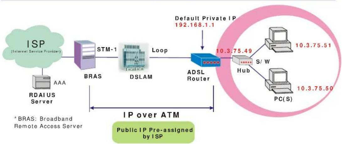
flowchart
graph LR
    A["ISP (Internet Service Provider)"] --> B["BRAS"]
    B --> C["DSLAM"]
    C --> D["ADSL Router"]
    D --> E["PC(S)"]
    E --> F["PC/S"]
    G["RDAIUS Server"] --> H["AAA"]
    I["Default Private IP 192.168.1.1"] --> D
    J["S/W"] --> K["Hub"]
    L["Public IP Pre-assigned by ISP"] --> M["IP over ATM"]
    N["* BRAS: Broadband Remote Access Server"] --> O["Loop"]
    O --> D
Description:
If you apply for multiple IP addresses from your ISP, you can assign these public IP addresses to the ADSL Router and public server, e.g., Web or FTP server. Typically the first IP is network address, the second is used as router IP address and the last one is subnet broadcasting. Other remaining IP addresses can be assigned to PCs on the LAN.
The following example uses the LAN IP address ranging from 10.3.75.49 to 10.3.75.54 and the subnet mask for LAN is 255.255.255.248. The WAN address is 10.3.70.1, and the subnet mask for WAN is 255.255.255.252.
In such circumstance, we do not assign any WAN IP.
Configuration:
- Start up your browser and type 192.168.1.1 as the address to enter this ADSL web-based manager.
- Go to Quick Start -Quick Setup. Uncheck Auto Scan Internet Connection (PVC).Type in the VCI and VPI value. Then click the Next button.
VPI-0
VCI-32 - On the Configure Internet Connection -Connection Type page, select the IP over ATM (IPoA) then click the Next button.
- In the WAN IP Settings page, select None for WAN IP address settings. Then, select Use the following DNS Server Address. Type in the Primary DNS server and Secondary DNS server. Uncheck Enable NAT. Then Click Next for next page.
Primary DNS server: 168.95.1.1
Secondary DNS server: 168.95.192.1 - In the Configure LAN side Settings page, type in the IP address and subnet mask for your LAN.
Primary IP Address: 192.168.1.1
Subnet mask: 255.255.255.0
Start IP Address: 192.168.1.2
End IP Address: 192.168.1.254 - Check Configure the second IP Address and Subnet Mask for LAN Interface and type in the second IP address and subnet mask. Then click Next.
Secondary IP Address: 10.3.75.49
Subnet mask: 255.255.255.248 -
Check the network information. Make sure the settings match the settings provided by ISP. Click Finish.
-
Set TCP/IP for your computer. Specify an IP Address, subnet mask and set default gateway. eg:
IP Address: 10.3.75.51
Subnet Mask: 255.255.255.248
Gateway: 10.3.75.49
- Now the router is well configured. You can access into Internet.
Unnumbered IP over ATM (IPoA) + NAT
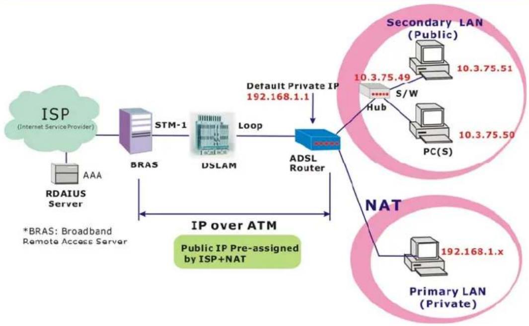
flowchart
graph TD
    A["ISP (Internet Service Provider)"] --> B["BRAS"]
    B --> C["STM-1"]
    C --> D["DSLAM"]
    D --> E["Default Private IP 192.168.1.1"]
    E --> F["ADSL Router"]
    F --> G["Primary LAN (Private)"]
    G --> H["NAT"]
    H --> I["Secondary LAN (Public)"]
    I --> J["S/W"]
    J --> K["Hub"]
    K --> L["PC(S)"]
    L --> M["10.3.75.50"]
    M --> N["S/W"]
    N --> O["10.3.75.49"]
    O --> P["Head"]
    P --> Q["DB"]
    Q --> R["Node"]
    R --> S["Node"]
    S --> T["Node"]
    T --> U["Node"]
    U --> V["Node"]
    V --> W["Node"]
    W --> X["Node"]
    X --> Y["Node"]
    Y --> Z["Node"]
    Z --> AA["Node"]
    AA --> AB["Node"]
    AB --> AC["Node"]
    AC --> AD["Node"]
    AD --> AE["Node"]
    AE --> AF["Node"]
    AF --> AG["Node"]
    AG --> AH["Node"]
    AH --> AI["Node"]
    AI --> AJ["Node"]
    AJ --> AK["Node"]
    AK --> AL["Node"]
    AL --> AM["Node"]
    AM --> AN["Node"]
    AN --> AO["Node"]
    AO --> AP["Node"]
    AP --> AQ["Node"]
    AQ --> AR["Node"]
    AR --> AS["Node"]
    AS --> AT["Node"]
    AT --> AU["Node"]
    AU --> AV["Node"]
    AV --> AW["Node"]
    AW --> AX["Node"]
    AX --> AY["Node"]
    AY --> AZ["Node"]
    AZ --> BA["Node"]
    BA --> BB["Node"]
    BB --> BC["Node"]
    BC --> BD["Node"]
    BD --> BE["Node"]
    BE --> BF["Node"]
    BF --> BG["Node"]
    BG --> BH["Node"]
    BH --> BI["Node"]
    BI --> BJ["Node"]
    BJ --> BK["Node"]
    BK --> BL["Node"]
    BL --> BM["Node"]
    BM --> BN["Node"]
    BN --> BO["Node"]
    BO --> BP["Node"]
    BP --> BQ["Node"]
    BQ --> BR["Node"]
    BR --> BS["Node"]
    BS --> BT["Node"]
    BT --> BU["Node"]
    BU --> BV["Node"]
    BV --> BW["Node"]
    BW --> BX["Node"]
    BX --> BY["Node"]
    BY --> BZ["Node"]
Description:
If you apply for multiple IP addresses from your ISP, you can assign these public IP addresses to the ADSL Router and public server, e.g., Web or FTP server. Typically the first IP is network address, the second is used as router IP address and the last one is subnet broadcasting. Other remaining IP addresses can be assigned to PCs on the LAN.
The following example uses the LAN IP address ranging from 10.3.75.49 to 10.3.75.54 and the subnet mask for LAN is 255.255.255.248. The WAN address is 10.3.70.1, and the subnet mask for WAN is 255.255.255.252.
In such circumstance, we enable NAT function but not assign any WAN IP.
Configuration:
- Start up your browser and type 192.168.1.1 as the address to enter this ADSL web-based manager.
- Go to Quick Start -Quick Setup. Uncheck Auto Scan Internet Connection (PVC). Type in the VCI and VPI value. Then click the Next button.
VPI-0
VCI-32 - On the Configure Internet Connection -Connection Type page, select the IP over ATM (IPoA) then click the Next button.
- In the WAN IP Settings page, select None for WAN IP address settings. Then, select Use the following DNS Server Address. Type in the Primary DNS server and Secondary DNS server. Click Next for next page.
Primary DNS server: 168.95.1.1
Secondary DNS server: 168.95.192.1 - Check the Enable NAT box. And click Next.
- In the Configure LAN side Settings page, type in the IP address and subnet mask for your LAN.
Primary IP Address: 192.168.1.1
Subnet mask: 255.255.255.0
Start IP Address: 192.168.1.2
End IP Address: 192.168.1.254
- Check Configure the second IP Address and Subnet Mask for LAN Interface and type in the second IP address and subnet mask. Then click Next.
Secondary IP Address: 10.3.75.49
Subnet mask: 255.255.255.248
-
Check the network information. Make sure the settings match the settings provided by ISP. Click Finish.
-
Now the router is well configured. You can access into Internet.
Bridge Mode
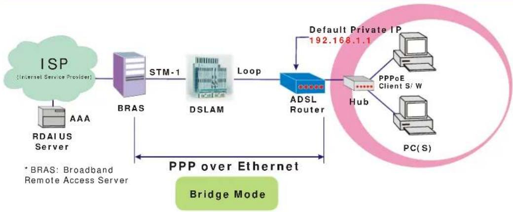
flowchart
graph LR
    A["ISP (Internet Service Provider)"] --> B["BRAS"]
    B --> C["STM-1"]
    C --> D["DSLAM"]
    D --> E["Loop"]
    E --> F["ADSL Router"]
    F --> G["Hub"]
    G --> H["PC(S)"]
    I["RDAIUS Server"] --> B
    J["Default Private IP 192.168.1.1"] --> F
    K["*BRAS: Broadband Remote Access Server"] --> B
    L["PPP over Ethernet Bridge Mode"] --> F
Description:
In this example, the ADSL Router acts as a bridge which bridging PC IP address from LAN to WAN. PC IP address can be a static public address that is pre-assigned by ISP or a dynamic public address that is assigned by ISP DHCP server, or can be got from PPPoE software.
Therefore, it does not require a public IP address. It only has a default private IP address (192.168.1.1) for management purpose.
Configuration:
-
Choose a client PC and set the IP as 192.168.1.x (x is between 2 and 254) and the gateway as 192.168.1.1.
-
Start up your browser and type 192.168.1.1 as the address to enter the web-based manager.
-
Go to Quick Start -Quick Setup. Uncheck Auto Scan Internet Connection (PVC). Type in the VCI and VPI value. Then click the Next button. eg:
VPI-0
VCI-32
-
On the Configure Internet Connection -Connection Type page, select the Bridging then click the Next button.
-
In the Configure LAN side Settings page, type in the IP address and subnet mask for your LAN. Finally click Next. eg:
Primary IP address:192.168.1.1
Subnet Mask:255.255.255.0
-
Check the network information. Make sure the settings match the settings provided by ISP. Click Finish.
-
Set TCP/IP for your computer. Specify an IP Address, subnet mask and set default gateway. eg: IP Address: 10.3.86.81
Subnet Mask: 255.255.255.248
Gateway: 10.3.86.1
- Click OK. Now the router is well configured. You can access into Internet.
Chapter 4: Web Configuration

Some users might want to set specific configuration for the router such as firewall, data transmission rate... and so on. This chapter will provide you advanced information of the web pages for the router for your reference.
Using Web-Based Manager
Once your host PC is properly configured, please proceed as follows:
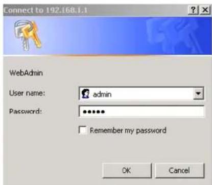
-
Start your web browser and type the private IP address of the ADSL Router in the URL field: 192.168.1.1.
-
After connecting to the device, you will be prompted to enter username and password. By default, the username is admin and the password is admin. See the example for running under Windows XP.
If you login successfully, the main page will appear. From now on the ADSL Router acts as a web server sending HTML pages/forms on your request. You can fill in these pages/forms and apply them to the ADSL Router.
Outline of Web Manager
For configure the web page, please use admin as the username and the password. The main screen will be shown as below.
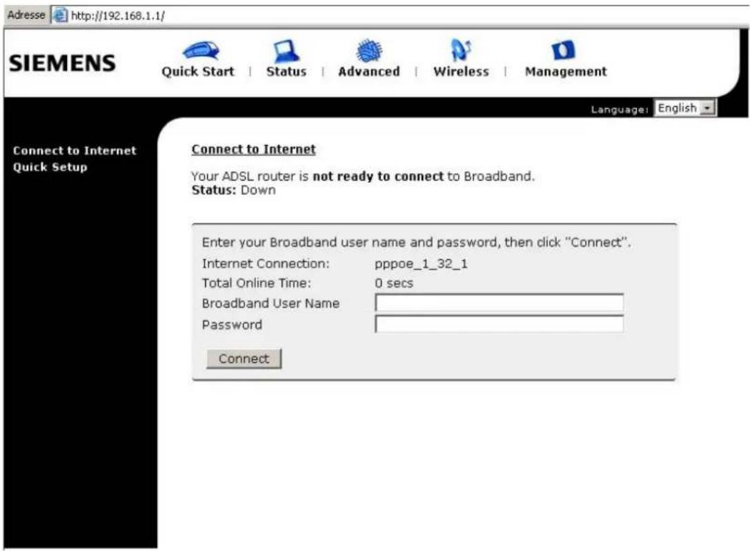
Title: It indicates the title of this management interface.
Main Menu: Includes Quick Start, Status, Advanced, Wireless and Management.
Main Window: It is the current workspace of the web management, containing configuration or status information.
To Have the New Settings Take Effect
After select or adjust the settings to your desire, your customizations will be saved to the flash memory before you restart the router. And only after restarting the router, your customizations take effect.
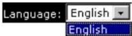
Language
On the top to the right of this web page, it provides a language drop down menu for you to choose proper language to help you to set.
Quick Start
The pages for the Quick Start provide user a quick way to set for the router. If you do not know more about the router, you can use the Quick Start pages to adjust basic settings to make your router activating.
Connect to Internet
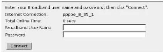
This is a quick way to connect to Internet by using PPPoE interface, click Connect to Internet to open the web page.
Enter the user name and password for your ADSL router and click Connect.
The system will connect automatically, then you can access Internet.
Connect to Internet
Your ADSL router is not ready to connect to Broadband. Status: Down
Quick Setup
The quick setup wizard will guide you to configure the DSL router through some steps.
Auto Scan Internet Connection (PVC): The default setting is checked. If there is no any PVC configured in your ADSL router, you can check this item. Otherwise, please uncheck this box.
VPI (Virtual Path Identifier): Identifies the virtual path between endpoints in an ATM network. The valid range is from 0 to 255. To enter the setting, please refer to the setting that the ISP gave you.
VCI (Virtual Channel Identifier):
Identifies the virtual channel endpoints in an ATM network. The valid range is from 32 to 65535 (1 to 31 is reserved for well-known protocols). To enter the setting, please refer to the setting that the ISP gave you.
After finished entering the VPI/VCI value, please click Next for next step.
Quick Setup
This Quick Setup will guide you through the steps necessary to configure your ADSL router.
Select the check box below to scan the Internet connection automatically. It is recommended that there is no any PVC configured in your ADSL router before performing auto-scanning connection.
Auto Scan Internet Connection (PVC)
Configure Internet Connection -- ATM PVC
Please enter VPI and VCI numbers for the Internet connection which is provided by your
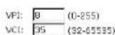
All original settings will be replaced by new settings after you finish these steps.

Connection Type
The system provides several protocols for you to choose. Your ISP will offer you the most suitable settings of the protocol. Before you set this page, please refer to the protocol that your ISP gave you.
After clicking on the Next button from the VPI/VCI web page, the following screen will appear. Please choose the connection type and encapsulation mode that you want to use and click Next for next page.
For example, PPP over Ethernet (PPPoE) in this screen is selected. Next, we are going to tell you different webpage for different protocol that you choose in this page.
Configure Internet Connection - Connection Type
Select the protocol and encapsulation type with the ATM PVC that your ISP has instructed you to use.
Protocol:
C PPP over ATM (PPPoA)
G PPP over Ethernet (PPPoE)
C IP over ATM (IPoA)
C Bridging
Encapsulation Type: LLC/SNAP
< Back Next>
PPP over ATM/ PPP over Ethernet
If the type you choose is PPP over ATM or PPP over Ethernet, please refer to the following information.
According to the ISP's configuration on the server, you can choose PPPoE and PPPoA modes. If the ISP provides PPPoE service, the connection type selection will be decided as whether the LAN side device is running a PPPoE client or the router is to run the PPPoE client. This router supports both situations simultaneously.
Choose PPPoA or PPPoE and click Next.
In this screen, you have to choose the settings for WAN IP. To get the IP address automatically, click the Obtain an IP address automatically radio button. Or click Use the following IP address button and enter the IP address for WAN interface.
Click Enable NAT if you want. As for the detailed NAT settings, it will be described in later sections.
Click Enable QoS for your necessity. It can improve the performance for selected classes of applications. Before you check this item, please assign the priorities for various applications from the Quality of Service menu of Advanced web page. Be aware that IP QoS also consumes system resources, the number of created PVCs will be reduced consequently.
The MTU means the maximum size of the packet that transmitted in the network. The packet of the data greater than the number set here will be divided into several packets for transmitting. Type in the number into the field of MTU. The default setting is 1492.
Click Next for next screen.
Configure Internet Connection - Connection Type
Select the protocol and encapsulation type with the ATM PVC that your ISP has instructed you to use.
Protocol:
C PPP over ATM (PPFOA)
G PPP over Ethernet (PPPoE)
C IP over ATM (IPoA)
C Bridging
Encapsulation Type: LLC/SNAP
< Back Next>
Configure Internet Connection - WAN IP Settings
Enter information provided to you by your ISP to configure the WAN IP settings.
Obtain an IP address automatically
C Use the following IP address:
WAN IP Address: 0.0.0.0
Enable NAT
Enable QoS
Enabling IP QoS for a PVC can improve performance for selected classes of applications. Please assign the priorities for various applications from the Advanced Quality of Service menu. Be aware that IP QoS also consumes system resources, the number of created PVCs will be reduced consequently.
MTU: 1492 (default: 1492)
< Back Next>
PPP Username:
Type in the username that you got from your ISP.
PPP Password:
Type in the password that you got from your ISP.
Always On:
Check this button to make the connection is always active.
Dial on Demand:
Click this button to make a connection while in demand. Enter the timeout to cut off the network connection if there is no activity for this router.
Manually Connect:
Click this button to make a connection by pressing the Connect button on the Advanced Setup- Internet-Connections web page.
In the Configure LAN side Settings web page, you have to fill in the data requested here.
Primary IP Address:
Type in the first IP address that you got from your ISP for your LAN connection.
Subnet Mask:
Type in the subnet mask that you got from your ISP for your LAN connection.
Configure the second IP Address and Subnet Mask for LAN interface:
Check this box to make another set of IP Address and Subnet Mask to connect to your router if they are not included in the range that DHCP server accepts.
Secondary IP Address:
Type in the second IP address that you got from your ISP for your LAN connection.
Subnet Mask:
Type in the subnet mask that you got from your ISP for your LAN connection.
MTU:
It means the maximum size of the packet that transmitted in the network. The packet of the data greater than the number set here will be divided into several packets for transmitting. Type in the number into the field of MTU. The default setting is 1500.
DHCP Server On:
Check this item if DHCP service is needed on the LAN. The router will assign IP address, gateway address for each of your
Configure Internet Connection - PPP User Name and Password
In order to establish the Internet connection, please enter PPP user name and password that your ISP has provided.
PPP User Name
PPP Password:
Session established by: C Always On
Dial on Demand, Idle Timer
Disconnect if no activity for 20 minutes
C. Manually Connect
Disconnect if no activity for 20 minutes
< Back Next >
Please type the username and password that you got from your ISP. Then click Next.
Configure LAN side Settings
Enter the ADSL router IP address and subnet mask for LAN interface and then enable DHCP server on LAN interface to provide IP address settings for your computers.
Primary IP Address: 192.168.1.1 Subnet Mask: 255.255.255.0
Configure secondary IP address and subnet mask
MTU: 1500 (default: 1500)
DHCP Server On Start IP:
192.168.1.2
End IP: 192.168.1.254
Lease Time: 1 days 0 hours 0 minutes
C DHCP Server Off
< Back NEXT>
On the Configure LAN side Settings web page, the IP address and subnet mask will be shown on it. You can modify them if needed.
Type in all the necessary settings and click Next for next page.
PCs.
Start IP Address:
Type in the start point IP address.
End IP Address:
Type in the end point IP address.
Leased Time:
Type in the duration for the time. The default is 1day.
DHCP Server Off:
Check this item if DHCP service isn't needed on the LAN.
You can check it at this time. If you find something is incorrect, click Back to change the settings.
If everything is OK, click Finish to accept these settings.
This Internet Connection -- Summary
Make sure that the settings below match the settings provided by your ISP.
Internet (WAN) Configuration:
| VPI / VCI | 8 / 35 |
| Connection Type | PPPoE LLC/SNAP, Dial on Demand, Idle Timer 20 mins |
| NAT | Enabled |
| WAN IP Address | Automatically Assigned |
| Default Gateway | Automatically Assigned |
| DNS Server | Automatically Assigned |
| QoS | Enabled |
LAN Configuration:
| Primary LAN IP | 192.160.1.1 / 255.255.255.0 |
| Secondary LAN IP | 0.0.0.0 / 0.0.0.0 |
| DHCP Server | On 192.160.1.2 ~ 192.160.1.254 |
| DHCP Lease Time | 1 days 0 hours 0 minutes |
Click "Finish" to accept these settings, and reboot the system. Click "Book" to make any modifications.
Now, the system will reboot to activate the new settings that you have done in this section.
Please wait for 2 minutes for restarting the router.
Reboot DSL Router
The DSL Router has been configured and is rebooting.
Close the DSL Router Configuration window and wait for 2 minutes before reopening your web browser. If necessary, reconfigure your PC's IP address to match your new configuration.
IP over ATM
If the type you have to choose is IP over ATM, please refer to the following information.
IPoA is an alternative of LAN emulation. It allows TCP/IP network to access ATM network and uses ATM quality of service's features.
Choose IPoA and click Next.
Configure Internet Connection - Connection Type
Select the protocol and encapsulation type with the ATM PVC that your ISP has instructed you to use.
Protocol:
C PPP over ATM (PPPoA)
C. PPP over Ethernet (PPPoE)
IP over ATM ([PoA)
C Bridging
Encapsulation Type: LLC/SNAP
< Back Next >
None:
If it is not necessary to set the WAN IP address, please click this button.
Obtain an IP address automatically:
Click this button to make the system get an IP address automatically.
WAN IP Address:
Type in the IP address that you got from ISP for the WAN interface.
WAN Subnet Mask:
Type in the subnet mask address that you got from ISP for the WAN interface.
Obtain DNS server address automatically:
Click this button to make the system get DNS server automatically.
Use the following DNS server address:
If you want to set DNS server by yourself, you have to click on this button to invoke the following entries.
Primary DNS server:
Type in your preferred DNS server that you got from ISP.
Secondary DNS server:
Type in the alternate DNS server that you got from ISP.
Click Enable NAT if you want. As for the detailed NAT settings, it will be described in later sections.
Click Enable QoS for your necessity.
It can improve the performance for selected classes of applications. Before you check this item, please assign the priorities for various applications from the Quality of Service menu of Advanced web page. Be aware that IP QoS also consumes system resources, the number of created PVCs will be reduced consequently.
Please type in the WAN IP address, Subnet Mask and DNS server addresses. Then Click Next to get the following page.
Configure Internet Connection - WAN IP Settings
Enter information provided to you by your ISP to configure the WAN IP settings.
C None
Obtain an IP address automatically
C use the following IP address:
WAN IP Address:
WAN Subnet Mask:
Obtain DNS server address automatically
C Use the following DNS server addresses:
Primary DNS server:
Secondary DNS server:
Enable NAT
Enable QoS
Enabling IP QoS for a PVC can improve performance for selected classes of applications. Please assign the priorities for various applications from the Advanced ..Quality of Service menu. Be aware that IP QoS also consumes system resources, the number of created PVCs will be reduced consequently.
< Back | Next >
In the Configure LAN side Settings web page, you have to fill in the data requested here.
Primary IP Address:
Type in the first IP address that you got from your ISP for your LAN connection.
Subnet Mask:
Type in the subnet mask that you got from your ISP for your LAN connection.
Configure the second IP Address and Subnet Mask for LAN interface:
Check this box to make another set of IP Address and Subnet Mask to connect to your router if they are not included in the range that DHCP server accepts.
Secondary IP Address:
Type in the second IP address that you got from your ISP for your LAN connection.
Subnet Mask:
Type in the subnet mask that you got from your ISP for your LAN connection.
DHCP Server On:
Check this item if DHCP service is needed on the LAN. The router will assign IP address, gateway address for each of your PCs.
Start IP Address:
Type in the start point IP address.
End IP Address:
Type in the end point IP address.
Leased Time:
Type in the duration for the time. The default is 1day.
DHCP Server Off:
Check this item if DHCP service isn't needed on the LAN.
You can check it at this time. If you find something is incorrect, click Back to change the settings. If everything is OK, click
Finish to accept these settings. And the following page will appear.
Configure LAN side Settings
Enter the ADSL router IP address and subnet mask for LAN interface and then enable DHCP server on LAN interface to provide IP address settings for your computers.
| Primary IP Address: | 192.168.1.1 |
| Subnet Mask: | 255.255.255.0 |
Configure secondary IP address and subnet mask
| Secondary IP Address: | 0.0.0.0 |
| Subnet Mask: | 0.0.0.0 |
| DHCP Server On | Start IP: | 192.168.1.2 |
| End IP: | 192.168.1.254 | |
| Lease Time: | 1 days 0 hours 0 minutes |
C DHCP Server Off
< Back Next >
On the Configure LAN side Settings web page, the IP address and subnet mask will be shown on it. You can modify them if needed. Click Next for next page.
This Internet Connection -- Summary
Make sure that the settings below match the settings provided by your ISP.
Internet (WAN) Configuration:
| VPI / VCI | 8 / 35 |
| Connection Type | JPoA LLC/SNAP |
| NAT | Enabled |
| WAN IP Address | Automatically Assigned |
| Default Gateway | Automatically Assigned |
| DNS Server | Automatically Assigned |
| QoS | Enabled |
LAN Configuration:
| Primary LAN IP | 192.168.1.1 / 255.255.255.0 |
| Secondary LAN IP | 0.0.0.0 / 0.0.0.0 |
| DHCP Server | On 192.168.1.2 ~ 192.168.1.254 |
| DHCP Lease Time | 1 days 0 hours 0 minutes |
Click "Finish" to accept these settings, and reboot the system. Click "Back" to make any modifications.
< Back Finish
Now, the system will reboot to activate the new settings that you have done in this section.
Please wait for 2 minutes for restarting the router.
Reboot DSL Router
The DSL Router has been configured and is rebooting.
Close the DSL Router Configuration window and wait for 2 minutes before reopening your web browser. If necessary, reconfigure your PC's IP address to match your new configuration.
Bridging
If the type you choose is Bridging, please refer to the following information.
The bridging mode can configure your router to send packets received on any port such as ATM PVC or Ethernet with a broadcast MAC address to all other ports.
Choose Bridging and click Next.
Configure Internet Connection - Connection Type
Select the protocol and encapsulation type with the ATM FVC that your ISP has instructed you to use.
Protocol:
C PPP over ATM (PPPOA)
C PPP over Ethernet (PPPoE)
C IP over ATM (IPoA)
Bridging
Encapsulation Type
LLC/SNAP
< Back Next >
None:
If it is not necessary to set the WAN IP address, please click this button.
Obtain an IP address automatically: Click this button to make the system get an IP address automatically.
WAN IP Address:
Type in the IP address that you got from ISP for the WAN interface.
WAN Subnet Mask:
Type in the subnet mask address that you got from ISP for the WAN interface.
Obtain DNS server address automatically:
Click this button to make the system get DNS server automatically.
Use the following DNS server address:
If you want to set DNS server by yourself, you have to click on this button to invoke the following entries.
Primary DNS server:
Type in your preferred DNS server that you got from ISP.
Secondary DNS server:
Type in the alternate DNS server that you got from ISP.
Click Enable NAT if you want. As for the detailed NAT settings, it will be described in later sections.
Click Enable QoS for your necessity.
It can improve the performance for selected classes of applications. Before you check this item, please assign the priorities for various applications from the Quality of Service menu of Advanced web page. Be aware that IP QoS also consumes system resources, the number of created PVCs will be reduced consequently.
In the Configure LAN side Settings web page, you have to fill in the data requested here.
Configure Internet Connection - WAN IP Setting
Enter information provided to you by your ISP to configure the WAN IP settings.
None
Obtain an IP address automatically
C Use the following IP address
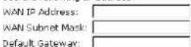
Obtain DNS server address automatically
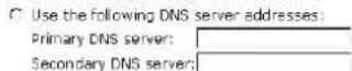
Enable NAT
Enable QoS
Enabling IP QoS for a PVC can improve performance for selected classes of applications. Please assign the priorities for various applications from the Advanced Quality of Service menu. Be aware that IP QoS also consumes system resources, the number of created PVCs will be reduced consequently.
< Back Next>
Primary IP Address:
Type in the IP address that you got from your ISP for LAN interface.
Subnet Mask:
Type in the subnet mask that you got from your ISP for LAN interface.
MTU:
It means the maximum size of the packet that transmitted in the network. The packet of the data greater than the number set here will be divided into several packets for transmitting. Type in the number into the field of MTU. The default setting is 1500.
DHCP Server On:
Check this item if DHCP service is needed on the LAN. The router will assign IP address, gateway address for each of your PCs.
Start IP Address:
Type in the start point IP address.
End IP Address:
Type in the end point IP address.
Leased Time:
Type in the duration for the time. The default is 1day.
DHCP Server Off:
Check this item if DHCP service isn't needed on the LAN.
Click Next to get into next web page.
You can check it at this time. If you find something is incorrect, click Back to change the settings. If everything is OK, click Finish to accept these settings. And the following page will appear.
Configure LAN side Settings
Enter the ADSL router IP address and subnet mask for LAN interface and then enable DHCP server on LAN interface to provide IP address settings for your computers.
| Primary IP Address: | 192.168.1.1 |
| Subnet Mask: | 255.255.255.0 |
Γ Configure secondary IP address and subnet mask
MTU: 1500 (default: 1500)
| DHCP Server On | Start IP: | 192.168.1.2 | |||
| End IP: | 192.168.1.254 | ||||
| Lease Time: | 1 days 0 hours 0 minutes | ||||
C DHCP Server Off
< Back Next >
This Internet Connection -- Summary
Make sure that the settings below match the settings provided by your ISP.
Internet (WAN) Configuration:
| VPI / VCI | 8 / 35 |
| Connection Type | Bridge LLC/SNAP |
| NAT | Enabled |
| WAN IP Address | Automatically Assigned |
| Default Gateway | Automatically Assigned |
| DNS Server | Automatically Assigned |
| QoS | Enabled |
LAN Configuration:
| Primary LAN IP | 192.168.1.1 / 255.255.255.0 |
| Secondary LAN IP | 0.0 0.0 / 0.0.0.0 |
| DHCP Server | On 192.168.1.2 ~ 192.168.1.254 |
| DHCP Lease Time | 1 days 0 hours 0 minutes |
Click "Finish" to accept these settings, and reboot the system. Click "Back" to make any modifications.
< Back Finish
Now, the system will reboot to activate the new settings that you have done in this section.
Please wait for 2 minutes for restarting the router.
Reboot DSL Router
The DSL Router has been configured and is rebooting.
Close the DSL Router Configuration window and wait for 2 minutes before reopening your web browser. If necessary, reconfigure your PC's IP address to match your new configuration.
Status
Overview
This page is displaying the current status for the DSL connection. It includes if the wireless network is enabled or not, lists the LAN IP address, default gateway, DNS servers IP address, firmware version, the period of activating the router, and so on. The system status will be changed according to the settings that you configured in the web pages.
Overview of Device Information
This information reflects the current status of your ADSL router.
| System Up Time | 00:01:03:38 |
| ADSL Speed (DS/US) | |
| LAN IP Address | 192.168.1.1 |
| Default Gateway | |
| Primary DNS server | |
| Secondary DNS server |
| Firmware Version | 2.21.05.06_A2p8018c1.d16d |
| Boot Loader Version | 1.0.37-21.6.4 |
| Wireless Driver Version | 3.91.39.0 (Wireless is enabled) |
| Wireless BSSID | 00:11:F5:4B:9E:45 |
| Ethernet MAC Address | 00:11:F5:4B:9E:42 |
ADSL Line
This page shows all information for ADSL. For knowing the quality of the ADSL connection, please click ADSL BER Test button to have advanced information.
Click More Information to show more detailed information about ADSL Line Status.
ADSL Line Status
Current adsl line status is as the below.
| Line Mode | Line State | Down | |
| Latency Type | Line Up Time Duration | N/A | |
| Line Coding | Line Up Count | 0 |
| Statistics | Downstream | Upstream |
| Line Rate | ||
| Attainable Line Rate | ||
| Noise Margin | ||
| Line Attenuation | ||
| Output Power |
More Information »
ADSL BER Test
ADSL BER Test
This test determines the quality of the ADSL connection. It is done by transferring idle cells containing a known pattern and comparing the received data with this known pattern to check for errors.
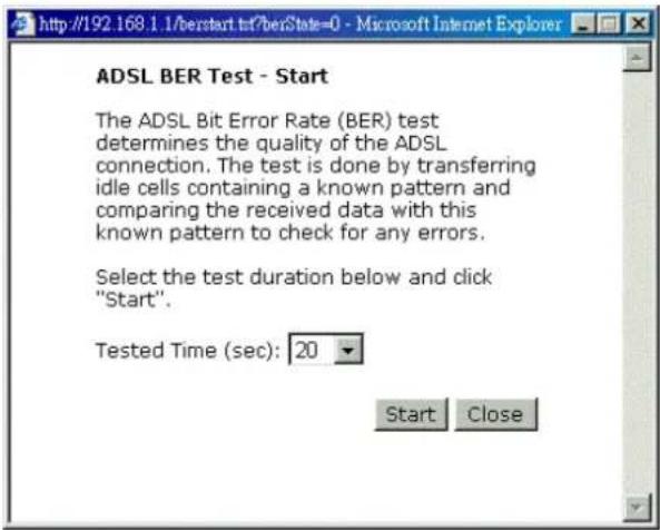
After select the test duration time and click Start, the following dialog appears to tell you the test is running. You can stop the test by click Stop or close this dialog by click Close.
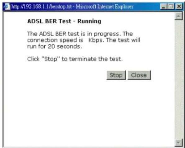
When the test is over, the result will be shown on the following dialog for your reference. Click Close to close this dialog.
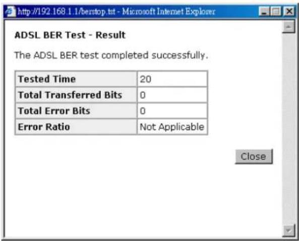
Internet Connection
This page displays the connection information for your router, such as PVC name, category, protocol, invoking NAT or not, IP address, link status and so on.
Internet Connection
Current Internet connections are listed below.
| PVC Name | VPI/VCI | Category | Protocol | NAT | QoS | WAN IP Address | Status / Online Time |
| pppoe_8_35_1 | 8/35 | UBR | PPPSE LLC/SNAP | On | On | Down 00:00:00:00 |
Traffic Statistics
This table shows the records of data going through the LAN and WAN interface. For each interface, cumulative totals are displayed for Received and Transmitted.
Traffic Statistics
The statistics of user data going through your ADSL router are listed below.
| Interface | Received | Transmitted | ||||||
| Bytes | Packets | Errors | Drops | Bytes | Packets | Errors | Drops | |
| Ethernet | 315000 | 2958 | 0 | 0 | 1168900 | 3946 | 0 | 0 |
| Wireless | 0 | 0 | 0 | 0 | 0 | 0 | 5 | 0 |
| WAN | 0 | 0 | 0 | 0 | 0 | 0 | 0 | 0 |

DHCP Table
This table shows all DHCP clients who get their IP addresses from your ADSL Router. For each DHCP client, it shows the Host Name, MAC Address, IP Address and the Lease Time.
DHCP Table
Those devices which get their IP addresses from your ADSL router are listed below.
| Host Name | MAC Address | IP Address | Lease Time |
| CN | 00:C1:26:0A:69:2B | 192.168.1.2 | 00:23:47:17 |
Wireless Client
This table shows the MAC address for all of wireless LAN clients currently associated to your DSL Router.
Wireless Clients Table
All of wireless LAN clients currently associated to your DSL Router are listed below.
NOTE: The list below might include wireless clients which are no longer connected to your DSL Router. You need to wait for a few seconds for the list to be fully updated.
MAC Address On-line Time
Routing Table
This table shows the routing method that your router uses.
Routing Table
All of current routing rules in your DSL Router are listed below.
| Destination | Netmask | Gateway | Interface | Metric |
| 192.168.1.0 | 255.255.255.0 | 0.0.0.0 | bro | 0 |
ARP Table
This table shows the IP address record for IP-to-Physical translation in your router.
ARP Table
The IP-to-Physical address translation entries recorded in your DSL Router are listed below.
| IP address | Physical Address | Interface | Type |
| 192.168.1.2 | 00:C1:26:0A:59:2B | br0 | Dynamic |
Advanced Setup
Local Network-IP Address
This page is the same as you can see in the Configure LAN side Settings page while running the Quick Setup. It allows you to set IP Address and Subnet Mask values for LAN interface.
Primary IP Address:
Type in the first IP address that you got from your ISP for your LAN connection.
Subnet Mask:
Type in the subnet mask that you got from your ISP for your LAN connection.
Host Name:
List the host name of this device.
Domain Name:
List the name of domain.
Configure the second IP Address and Subnet Mask for LAN interface:
Check this box to make another set of IP Address and Subnet Mask to connect to your router if they are not included in the range that DHCP server accepts.
Secondary IP Address:
Type in the second IP address that you got from your ISP for your LAN connection.
Subnet Mask:
Type in the subnet mask that you got from your ISP for your LAN connection.
MTU:
It means the maximum size of the packet that transmitted in the network. The packet of the data greater than the number set here will be divided into several packets for transmitting. Type in the number into the field of MTU. The default setting is 1500.
Apply:
Click this button to activate the settings listed above.
Local Network - DHCP Server
This allows you to set DHCP server on LAN interface.
LAN IP Address Configuration
Enter the ADSL router IP address and subnet mask for LAN interface.
| Primary IP Address: | 192.160.1.1 |
| Subnet Mask: | 255.255.255.0 |
| Host Name: | RTA1025W |
| Domain Name: | home |
Configure secondary IP address and subnet mask.
| MTU: | 1500 (default: 1500) |
Apply New settings only take effect after your ADSL router is rebooted. If necessary, reconfigure your PC's IP address to match new settings.
DHCP Server On:
Check this item if DHCP service is needed on the LAN. The router will assign IP address, gateway address for each of your PCs.
Start IP Address:
Type in the start point IP address.
End IP Address:
Type in the end point IP address.
Leased Time:
Type in the duration for the time. The default is 1day.
Relay On:
Click this button to have a relay setting. And type in the Server IP in this field.
Server and Relay Off:
Check this item if DHCP service isn't needed on the LAN.
Apply:
Click this button to activate the settings listed above.
You can reserve one specific IP address for a certain PC for certain purpose. Simply add a mapping entry of MAC address & IP address for that PC by pressing the View Reserved IP Address List button. The following picture will appear.
Click the Add button to open another dialog as follows. On PCs MAC Address and Assigned IP Address boxes, please type in the correct information for the one that you want to add and click Apply.
DHCP Server Configuration
Enabling DHCP Server on LAN interface can provide the proper IP address settings to your computer.
NOTE: New settings only take effect after the router is rebooted. If necessary, reconfigure your PC's IP address to match new settings.
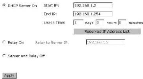
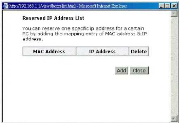
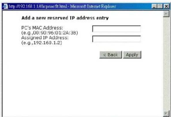
The new one will be shown on the dialog right away. That is, the specified address will be reserved and not be assigned by DHCP for other computer.
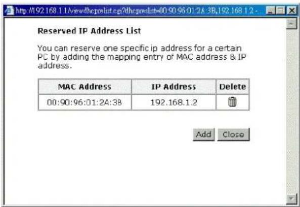
Local Network - UPnP
The UPnP is available only for Windows XP. If you are not user of Windows XP, this page does not have any meaning to you.
This page allows you to enable the UPnP function through the web page for your router.
UPnP Configuration
Enabling the UPnP 1GD and NAT Traversal function allows the users to perform more applications behind NAT without additional configuration settings or ALG support on your ADSL router.


Internet-Connections Setting
To set WAN settings for each service, please open Advanced- Internet Setting. This page allows you to add new WAN settings, to edit or remove created WAN settings.
If you click the Connect line under the PVC Name item, the system will connect to WAN automatically. If the WAN connection is OK, you can check the detailed information directly.
Internet Connection Configuration
Choose Add or Edit to configure Internet connection. Choose Finish to apply the changes and reboot the system.
| PVC Name | VPI/VCI | Category | Protocol | NAT | QoS | WAN IP Address | MTU | Edit |
| pppoe_B_35_1 Connect » | 8/35 | UBR | PPPoE LLC/SNAP | On | On | Auto assigned | 1492 |
The Internet connection is NOT active if PVC name is marked with (7). You need to click "Finish" to apply changes and reboot the system for activating this PVC.

Adding a New One
You have to type in the VPI and VCI values in the entry boxes. Then click Next. The screen will get into the Connection Type page of Quick Setup and ask you to fill in the data according to the request of the screen. Refer to Quick Setup for more information if you don't know how to set the configuration.
To add a new WAN connection, please click the Add button. The following screen appears.
VPI (Virtual Path Identifier):
Identifies the virtual path between endpoints in an ATM network. The valid range is from 0 to 255. You cannot type in the number randomly if you desire. Please refer to the value that your ISP gave.
Configure Internet Connection -- ATM PVC
Please enter VP] and VCI numbers for the [internet connection which is provided by your ISP.
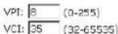
Service Category:

VCI (Virtual Channel Identifier):
Identifies the virtual channel endpoints in an ATM network. The valid range is from 32 to 65535 (1 to 31 is reserved for well-known protocols). You cannot type in the number randomly if you desire. Please refer to the value that your ISP gave.
Service Category:
It decides the size and rate for the packets of the data in different service type. There are five categories provided here for your selection. Please choose any one of it as you desired.

If you choose Non Realtime VBR, you have to type in the following data.
The range for Peak Cell Rate is from 1 to 1690.
The range for Sustainable Cell Rate is from 1 to 1689 and must be smaller than Peak Cell Rate.
The range for Maximum Burst Size is from 1 to 100.
Configure Internet Connection -- ATM PVC
Please enter VPI and VC1 numbers for the Internet connection which is provided by your ISP.
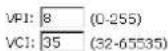
Service Category:
Peak Cell Rate: Sustainable Cell Rate:
Maximum Burst Size

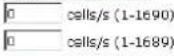
cells/s (1-100)

After click Next, you will see the web page listed as the right. Choose the protocol that you want. And click Next again.
Configure Internet Connection - Connection Type
Select the protocol and encapsulation type with the ATM PVC that your ISP has instructed you to use.
C PPP over Ethernet (PPPoE) C Bridging


The WAN IP settings will differ slightly according to the protocol that you choose. This graphic is the one that you will get if you choose to add a new interface of PPPoA/PPPoE mode. You can check Enable NAT or Enable Qos for your necessity. And you can set the MTU value in this page.
Configure Internet Connection - WAN IP Settings
Enter information provided to you by your ISP to configure the WAN IP settings.
Obtain an IP address automatically
C Use the following IP address: WAN IP Address: 0.0.0.0
Enable NAT
Enable QoS
Enabling IP QoS for a PVC can improve performance for selected classes of applications. Please assign the priorities for various applications from the Advanced...Quality of Service menu. Be aware that IP QoS also consumes system resources, the number of created PVCs will be reduced consequently.
MTU: 1492 (default: 1492)

If you want to add a new interface of PPPoE mode and choose PPPoE from the previous web page, you will get a web page as the graphic listed in right side.
Please refer to Quick Setup for more information if you don't know how to set the configuration.
Configure Internet Connection - PPP User Name and Password
In order to establish the Internet connection, please enter PPP user name and password that your ISP has provided.
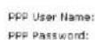

Session established by:
C Always On Dial on Demand Disconnect if no activity for 20 minutes C Manually Connect Disconnect if no activity for 20 minutes

If you want to add a new interface of Bridging mode and choose Bridging from the previous web page, you will get a web page as the graphic listed in right side.
Please refer to Quick Setup for more information if you don't know how to set the configuration.
Configure Internet Connection - WAN IP Setting
Enter information provided to you by your ISP to configure the WAN IP settings.
None Obtain an IP address automatically Use the following IP address: WAN IP Address: WAN Subnet Mask: Default Gateway:
Obtain DNS server address automatically
C Use the following DNS server addresses: Primary DNS server: Secondary DNS server:
Enable NAT
Enable QoS
Enabling IP QoS for a PVC can improve performance for selected classes of applications. Please assign the priorities for various applications from the Advanced Quality of Service menu, be aware that IP QoS also consumes system resources, the number of created PVCs will be reduced consequently.

Internet-DNS Server
If Enable Automatic Assigned DNS checkbox is selected, this router will accept the first received DNS assignment from one of the PPPoA, PPPoE or MER/DHCP enabled PVC(s) during the connection establishment. If the checkbox is not selected, it is necessary for you to enter the primary and optional secondary DNS server IP addresses. After type in the address, click Apply button to save it and invoke it.
Enable Automatic Assigned DNS:
Check this box to enable this function, or uncheck this box to disable it.
Primary DNS server:
Type in your primary DNS server.
Secondary DNS server:
Type in the secondary DNS server.
If you are satisfied the settings, click Apply.
DNS Server Configuration
If Enable Automatic Assigned DNS checkbox is selected, this router will accept the first received DNS assignment from the PPPoA, PPPoE or MER/DHCP enabled PVC(s) during the connection establishment. If the checkbox is not selected, enter the primary and optional secondary DNS server IP addresses. Click "Apply" to save it.

Enable Automatic Assigned DNS
Primary DNS server
Secondary DNS server

If changing from unselected Automatic Assigned DNS to selected Automatic Assigned DNS, you must restart your ADSL router to get DNS addresses automatically.
Internet-IGMP Proxy
The Internet Group Management Protocol (IGMP) is an Internet protocol that provides a way for an Internet computer to report its multicast group membership to adjacent routers.
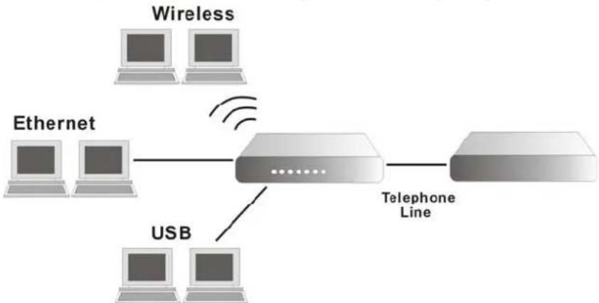
flowchart
graph TD
    A["Wireless"] -->|Wireless| B["Router"]
    C["Ethernet"] -->|Wireless| B
    D["USB"] -->|Wireless| B
    B --> E["Telephone Line"]
The hosts interact with the system through the exchange of IGMP messages. When you want to configure IGMP proxy, the system will interact with other router through the exchange of IGMP messages. However, when acting as the proxy, the system performs the host portion of the IGMP task as follows:
When it is queried, the system will send group membership reports to the group.
When one of the hosts joins a multicast address group to which none of other hosts belong, the system will send unsolicited group membership reports to that group.
When the last of hosts in a particular multicast group leaves the group, the system will send a leave group membership report to the routers group.
Internet Connection:
This field displays the internet connection that you currently use.
IGMP Proxy Enabled:
Check this box to enable this function or uncheck this box to disable this function.
After finish the settings, click Apply.
IGMP Proxy Configuration
Enabling IGMP proxy function can allow the users on your local network to play the multimedia (video or audio) which sent from the servers on the Internet.
| Internet Connection | IGMP Proxy Enabled |
| pppoe_8_35_1 |

Internet - ADSL Settings
Enable ADSL Port:
Check this box to enable this function. It simply invokes the line mode that you choose here for the router.
ADSL Settings
Enable ADSL Port
Select the support of line modes:
F 6.dmt
Glite
T1.413
ADSL2
READSL2
ADSL2+
Annex M
Capability Enabled:
Bitswap
Seamless Rate Adaptation
Apply
Select the support of line modes:
There are several selections for your choosing. Select the one that you need. For Example, if you want to change one or more physical layer parameters while the ATU-x is in data transfer state, and the transmission errors will not be present, please choose ADSL2.
Capability Enabled:
Two items are provided here for you to choose.
Bitswap:
It is a mandatory receiver initiated feature to maintain the operating conditions of the modem during changing environment conditions. It reallocates the data bits and power among the allowed carriers without modification of the higher layer control parameters in the ATU. After a bit swapping reconfiguration, the total data rate and the data rate on each latency path is unchanged. Check this box to enable the function. If not, uncheck this box to close the function.
Seamless Rate Adaptation:
It enables the ADSL2 system to change the data rate of the connection while in operation without any service interruption or bit errors. Check this box to enable the function. If not, uncheck this box to close the function.
IP Routing - Static Route
Routing Table shows all static route status and allows you to add new static IP route or delete IP route. A Static IP Routing is a manually defined path, which determines the data transmitting route. If your local network is composed of multiple subnets, you may want to specify a routing path to the routing table.
Destination Network Address:
Display the IP address that the data packets are to be sent.
Static Route
Current static routes:
| Destination | Netmask | Gateway | WAN Interface | Delete |
Add
Netmask:
Display the subnet mask that the data transmitting is passing through.
Gateway:
Display the gateway that the data transmitting is passing through.
WAN Interface:
Display the interface that the data transmitting is passing through.
Delete:
Allow you to remove the selected static route settings.
Adding a New One
To add a static route, please choose Static Route - Add. Type the destination network address, subnet mask and gateway that you get from ISP and click Apply.
Destination Network Address:
The destination IP address of the network where data packets are to be sent.
Subnet Mask:
Type in the subnet mask that you got from ISP.
Gateway IP Address:
Click this button to invoke this function. Type in the gateway that you got from ISP.
WAN Interface:
Click this button to invoke this function and choose the one from the drop down menu.
Add New Static Route
Enter the Destination Network Address, Netmask, Gateway or available WAN interface then click "Apply" to add the entry to the routing table.
Destination Network
(For default route, type 0.0.0.0 or leave blank)
IP Address:
Netmask:
Forward Packets to
G Gateway IP Address:
C WAN Interface:
< Back | Apply
Click Apply to view the routing result. This page shows all the routing table of data packets going through your ADSL Router.
Remove Static Route
If you don't want the static route that you created, please click the icon under Delete from Routing Table.
Static Route
Current static routes
| Destination | Netmask | Gateway | WAN Interface | Delete |
| 0.0.0.0 | 255.255.255.0 | 192.168.1.1 |
Add
A dialog appears to ask you to confirm the action. Click Yes to remove the static route, or click No to keep the setting.
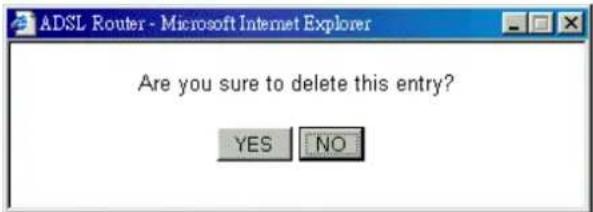
Configuring Other Routers on Your LAN
It is essential that all IP packets for devices that are not on the local LAN can be passed to the Router, so that they can be forwarded to the external LAN, WAN, or Internet. To achieve this, the local LAN must be configured to use the Router as the default route or default gateway.
Local Router
The local router is the Router installed on the same LAN segment as the Router. This router requires that the default route is the Router itself. Typically, routers have a special entry for the default route. It should be configured as follows.
Destination:
Normally 0.0.0.0 but check your router documentation.
Subnet Mask:
Normally 0.0.0.0 but check your router documentation.
Gateway:
The IP Address of the Router.
Other Routers on the Local LAN
Other routers on the local LAN must use the Router's Local Router as the Default Route. The entries will be the same as the Router's local router, with the exception of the Gateway IP Address.
For a router with a direct connection to the Router's local Router, the Gateway IP Address is the address of the Router's local router.
For routers which must forward packets to another router before reaching the Router's local router, the Gateway IP Address is the address of the intermediate router.
Example - Static Route
Here provides you an example of Static Route.
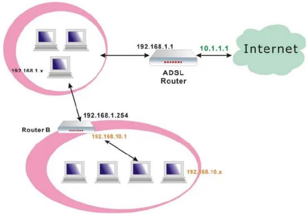
flowchart
graph TD
    A["192.168.1.x"] --> B["192.168.1.1"]
    B --> C["ADSL Router"]
    C --> D["Internet"]
    E["Router B"] --> F["192.168.1.254"]
    F --> G["192.168.10.1"]
    G --> H["192.168.10.x"]
    style A fill:#f9f,stroke:#333
    style E fill:#f9f,stroke:#333
    style B fill:#ccf,stroke:#333
    style C fill:#ccf,stroke:#333
    style F fill:#ccf,stroke:#333
    style G fill:#ccf,stroke:#333
    style H fill:#ccf,stroke:#333
For the Router's Routing Table
For the LAN shown above, with 2 routers and 3 LAN segments, the Router requires to add 2 static routes as follows:
ADSL Router
Destination
192.168.10.0
Subnet Mask 255.255.255.0 (Standard Class C)
Gateway
192.168.1.254 (Router B)
IP Routing – Dynamic Routing
Routing Information Protocol (RIP) is utilized as a means of exchanging routing information between routers. It helps the routers to determine optimal routes. This page allows you to enable/disable this function.
RIP Version:
It incorporates the RIP information when receiving and broadcasting the RIP packets. From the drop down list, select a RIP version to be accepted, 1, 2 or both.
Operation Mode:
There are two modes for you to choose, Active and Passive. Select Active for transmitting and receiving data, or select Passive for receiving data only.
Enabled:
Click Enabled to enable the RIP function on
Dynamic Routing
You can enable RIP function on several interfaces of your ADSL router. Select the desired RIP version and operation mode, then to the 'Enabled' checkbox to enable RIP when you click "Apply", or leave it unticked if you would like to disable RIP on those interfaces.
| Interface | RIP Version | Operation Mode | Enabled |
| LAN | 2 | Active | |
| pppce_8_35_1 | 2 | Passive |
| Apply |
different interface. Otherwise, disable this function.
Click Apply to invoke the settings set here.
Virtual Server-Port Forwarding
The Router implements NAT to let your entire local network appear as a single machine to the Internet. The typical situation is that you have local servers for different services and you want to make them publicly accessible. With NAT applied, it will translate the internal IP addresses of these servers to a single IP address that is unique on the Internet. NAT function not only eliminates the need for multiple public IP addresses but also provides a measure of security for your LAN.
When the router receives an incoming IP packet requesting for access to your local server, the router will recognize the service type according to the port number in this packet (e.g., port 80 indicates HTTP service and port 21 indicates FTP service). By specifying the port number, you tell the router which service should be forwarded to the local IP address you specify.
After you setting the virtual server you should modify the filter rule whichever port and service you set on virtual server. Because the firewall has protect the route by filter rule so that you should update the filter rule after you set up virtual server.
Virtual Server allows you to make servers on your LAN accessible to Internet users. Normally, Internet users would not be able to access a server on your LAN because:
☐ Your server does not have a valid external IP Address.
□ Attempts to connect to devices on your LAN are blocked by the firewall in this device.
The Virtual Server feature solves these problems and allows Internet users to connect to your servers, as illustrated below:
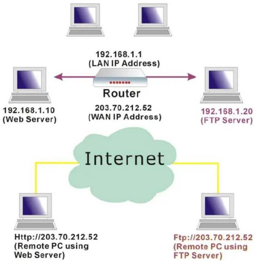
flowchart
graph TD
    A["Router"] -->|LAN IP Address 192.168.1.1| B["192.168.1.10 (Web Server)"]
    A -->|LAN IP Address 203.70.212.52| C["192.168.1.20 (FTP Server)"]
    B --> D["Internet"]
    C --> D
    D --> E["Http://203.70.212.52 (Remote PC using Web Server)"]
    D --> F["Ftp://203.70.212.52 (Remote PC using FTP Server)"]
IP Address seen by Internet Users
Please note that, in the above picture, both Internet users are connecting to the same IP address, but using different protocols.
To Internet users, all virtual servers on your LAN have the same IP Address. This IP Address is allocated by your ISP. This address should be static, rather than dynamic, to make it easier for Internet users to connect to your Servers. However, you can use Dynamic DNS feature to allow users to connect to your virtual servers by using a URL, instead of an IP address.
To set a virtual server, please open the Virtual Servers item from the Advanced Setup - NAT menu.
Port Forwarding
Create the port forwarding rules to allow certain applications or server software to work on your computers if the Internet connection uses NAT.
| Application Name | External Packet | Internal Host | Delete | |||
| IP Address | Protocol | Port | IP Address | Port | ||

Add New Port Forwarding
To add a new Port Forwarding, please click Add from the Port Forwarding web page.
Pre-defined
Choose one of the services type from the first drop down list, such as Audio/Video, Games and so on. In the second drop down list, choose the name of the application that you want to use with the type that you select in the first list.
User defined:
Type a new service name for building a customized service for specific reason.
Add New Port Forwarding Rule
Application Name:
Pre-defined:
c User defined:
From Internet Host IP Address:
Forward to Internal Host IP Address:

Add New Port Forwarding Rule
Application Name:
- Pre-defined:
C User defined:
From Internet Host IP
Forward to [Internal H
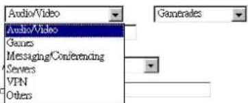

Add New Port Forwarding Rule
Application Name:
6 Pre-defined:
C User defined:

From Internet Host IP Address:
Forward to Internal Host IP Address:
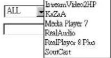

From Internet Host IP Address:
Select the initial place for port forwarding. If you choose SINGLE, a box will appear for you to fill in the IP address for the specific host. And, if you choose SUBNET, the boxes of IP and Subnet will appear for you to fill in the IP address and subnet mask for the specific host as the start point.
From Internet Host IP Address:
Forward to Internal Host IP Address:
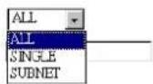

Forwarded to Internet Host IP Address:
Type in the address for the host used as the place that information will be forwarded.
IP addresses can be automatically redirected to local servers configured with private IP addresses. In other words, depending on the requested service (TCP/UDP port number), the router redirects the external service request to the appropriate server (located at another internal IP address).
After adding a new virtual server, click Apply.
The following screen will be shown to display the status for new ones.
If you do not want the new server that you added, please check the Delete box of that one and click the Delete button to discard it.
Or if you want to add another one again, click Add to add a new one.
Port Forwarding
Create the port forwarding rules to allow certain applications or server software to work on your computers if the Internet connection uses NAT.
| Application Name | External Packet | Internal Host | Delete | |||
| IP Address | Protocol | Port | IP Address | Port | ||
| Camerades | ALL | TCP/UDP | 2047 - 2048 | 192.16B 1.200 | 2047 - 2048 | |
Select All

Connecting to the Virtual Servers
Once configured, anyone on the Internet can connect to your Virtual Servers. They must use the Internet IP Address (the IP Address allocated to you by your ISP.) For example,
Http://203.70.212.52
Ftp://203.70.212.52
It is more convenient if you are using a Fixed IP Address from your ISP, rather than Dynamic. However, you can use the Dynamic DNS feature to allow users to connect to your Virtual Server through a URL, rather than an IP Address.
Virtual Server-Port Triggering
When the router detects outbound traffic on a specific port, it will set up the port forwarding rules temporarily on the port ranges that you specify to allow inbound traffic. It is supposed to increase the support for Internet gaming, video conferencing, and Internet telephony due to the applications require multiple connection.
To add a new port triggering, click Add to open this web page. Than choose an application name from the Pre-defined list box. The system provides 9 items for your choice.
Port Triggering
Port triggering function is a conditional port forwarding feature. When your ADSL router detects outbound traffic on a specific port (trigger port), it will set up the port forwarding rules temporarily on the port ranges you specify to allow inbound traffic. This is supposed to increase the support for Internet gaming, video conferencing, and Internet telephony due to these applications require multiple connection.
| Application Name | Trigger | Open | Delete | ||
| Protocol | Port | Protocol | Port | ||

Add New Port Triggering Rule
Application Name:
G Pre-defined:

C User defined:

Add New Port Triggering Rule
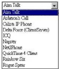
Or define by yourself by typing the words into the field of User defined.
Click Apply to complete the setting.
Virtual Server - DMZ Host
Direct Mapping Zone (DMZ) uses a technology that makes Router forwarding all incoming packet to internal specific server.
To close the function of DMZ Host, please click Discarded.
To activate a DMZ host, please click Forwarded to the DMZ host radio button and type the IP Address into the field of IP address of DMZ host, then click Apply.
DMZ Host
A DMZ host is a computer on your local network that can be accessed from the Internet regardless of port forwarding and firewall settings.
Those IP packets from the Internet that do NOT belong to any applications configured in the port forwarding table will be:


This feature allows one computer on your LAN to be exposed to all users on the Internet, allowing unrestricted 2-way communication between the specified IP address and other Internet users or Servers.
☐ This allows almost any application to be used on the specified IP address.
☐ The specified IP address will receive all “Unknown” connections and data.
☐ If the DMZ feature is enabled, you must type in numbers to specify an IP address.
☐ The DMZ feature can be Enabled and Disabled on the NAT setting screen.
Virtual Server - Dynamic DNS
The Dynamic DNS (Dynamic Domain Nasme System) combines both functions of DNS and DHCP to map a dynamic IP into a fixed domain name. This page allows you to access into virtual servers with a domain name and password.
Dynamic DNS :
Selects Enable to enable DDNS; select Disabled to disable this function.
Internet Connection :
Selects the interface that you want to use for connecting Internet.
User Name :
Type in the user name that you registered in www.dyndns.org.
Password :
Type in the password that you registered in www.dyndns.org.
Domain Name :
Type in the domain name that you registered in www.dyndns.org. You can use letters and dash for naming, yet other characters are not allowed to use for preventing from making troubles.
Status :
It displays current status.
Dynamic DNS Configuration
This page allows you to provide Internet users with a domain name (instead of an IP address) to access your virtual servers. This ADSL router supports dynamic DNS service provided by the provider 'http://www.dyrdns.org' or http://www.tzq.com. Please register this service at these providers first.
Dynamic DNS: C Disabled Enabled
Dynamic DNS Provider: DynDNS.org
Internet Connection: pppoe_8_35_1
User Name:
Password:
Domain Name:
Status:
Apply
Firewall
The firewall is a software that interrupts the data between the Internet and your computer. It is the TCP/IP equivalent of a security gate at the entrance to your company. All data must pass through it, and the firewall (functions as a security guard) will allow only authorized data to be passed into the LAN.
What the firewall can do? It can:
□ deny or permit any packet from passing through explicitly
□ distinguish between various interfaces and match on the following fields:
◆ source and destination IP address
◆ port
To keep track of the performance of IP Filter, a logging device is used which supports logging of the TCP/UDP and IP packet headers and the first 129 bytes of the packet (including headers) when a packet is successfully passed through, a packet is blocked from passing through and it matches a rule setup to look for suspicious packets
Filtering by IP address
An example for firewall setup:
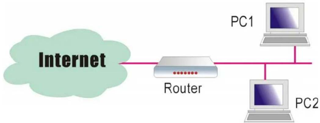
flowchart
graph LR
    A["Internet"] --> B["Router"]
    B --> C["PC1"]
    B --> D["PC2"]
This picture is the most common and easiest way to employ the firewall. Basically, you can install a packet-filtering router at the Internet gateway and then configures the filter rule in the router to block or filter protocols and addresses. The systems behind the router usually have a direct access to the Internet, however some dangerous services such as NIS and NFS are usually blocked.
For the security of your router, set the firewall is an important issue.
Choose Disabled to disable the firewall function. Click Enabled to invoke the settings that you set in this web page.
IP Filtering
This page allows you to specify the IP packet filtering rules to prevent the services accessed from the Internet hosts or limit the Internet access for local hosts.

To open the IP Filtering, please click the Enabled radio button. The web page will be shown as the right picture.
Select the direction to filter packets:
The way of the data transmission. In Bound means the data is transferred from outside onto your computer. Out Bound means the data is transferred from your computer onto outside through Internet. Please choose
Outbound traffic or Inbound traffic as the direction for filtering packets.
IP Filtering
This page allows you to specify the IP packet filtering rules to prevent the services accessed from the Internet hosts or limit the Internet access for local hosts.

Select the direction to filter packets: ☑ Outbound traffic ☐ Inbound traffic

Add
Then, to add a new IP Filtering, click Add.
This page provides some settings for you to adjust for adding a new outbound IP Filtering.
Allow Traffic:
No stops the data transmission, Yes lets the data pass through.
Add New Outbound IP Filtering Rule
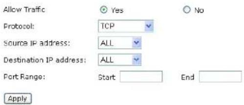
Protocol:
Here provide several default policies for security levels for you to choose. If you don't want to use the predefined setting, you can use User Defined to set a customized protocol for your necessity. When you choose User Defined setting, you have to type in a port number in the "as" field.
Protocol:
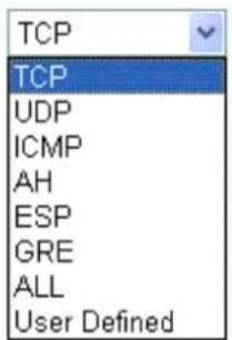
Add New Outbound IP Filtering Rule

Source/Destination IP address:
To specify IP address to allow or deny data transmission, please pull down the drop-down menu to choose a proper one.
All: This setting means that all the IP addressed in the network are allowed or denied to pass through in Internet. If you choose Single, an IP address field will appear to the right side. You have to type in the specific IP address as the start/end point to let the router identify for granting or denying pass through. If you choose Subnet, the IP address and Netmask will appear to the right side. Please type in the specific IP address and Netmask as the start/end point to let the router identify for granting or denying pass through.
Port Range:
The port range is from 0 to 65535. Please type in the start point and end point for the IP Filtering.
After finish the settings, click Apply. A new one will be added and shown on the web page.
Source IP address:
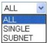
Add New Outbound IP Filtering Rule
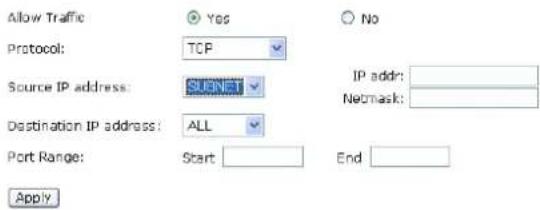
A new IP filtering setting for Outbound traffic is created in the web page. To edit the setting, please click the pencil mark to get into the editing page. To delete the setting, click the trash mark to erase it. To set another IP filtering, click Add again.
IP Filtering
This page allows you to specify the IP packet filtering rules to prevent the services accessed from the Internet hosts or limit the Internet access for local hosts.
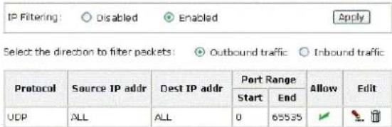
Add
For adding a new Inbound IP Filtering, click Inbound traffic in the item of Select the direction to filter packets. Use the same way to add a new one as stated above.
Add New Inbound IP Filtering Rule
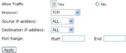
Quality of Service
QoS (Quality of Service) is an industry-wide initiative to provide preferential treatment to certain subsets of data, enabling that data to traverse the Internet or intranet with higher quality transmission service.
Bridge QoS
To classify the upstream traffic by assigning the transmission priority for data of different users, please use Bridge QoS to prioritize the data transmission.
The Bridge QoS allows you to set the settings based on layer two IP packets.
Bridge QoS
This page allows you to classify the upstream traffic (to the Internet) by assigning the transmission priority for various user data. Bridge QoS function prioritizes the data transmission based on layer 2 bridge packets.

Traffic Class Name:
Type in a name as the traffic class for identification.
802.1p Priority:
Each incoming packet will be mapped to a specific priority level, so that these levels may be acted on individually to deliver traffic differentiation. Please choose the number (from 0 to 7) for the 802.1p Priority.
Traffic Priority:
There are three options – Low, Medium, and High that you can choose.
IP Precedence:
The number you choose here decides the type of the IP address processed. No change
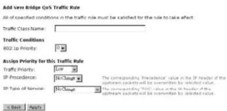
is the default setting.
IP type of Service:
The system provides some types of service for you to choose. The meaning of each type is the same as the denotation. The default one is No change.
IPQoS
To classify the upstream traffic by assigning the transmission priority of the data for different users, please use IP QoS to prioritize the data transmission.
The IP QoS allows you to set the settings based on layer three IP packets.
To add a new QoS setting, please Add in the page of Quality of Service, a page same as the right side will appear.
Traffic Class Name:
Type in a name as the traffic class for identification.
IP QoS
This page allows you to classify the upstream traffic (to the Internet) by assigning the transmission priority for various user data. JP QoS function prioritizes the data transmission based on layer 3 IP packets.
| Traffic Name | Priority | IP Precedence | IP TOS | Protocol | Source IP Source port | Dest IP Dest port | Delete |
| Add | |||||||
Add New IP QoS Traffic Rule
All of specified conditions in the traffic rule must be satisfied for the rule to take effect.
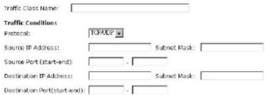
Assign Priority for this Traffic Rule


Protocol:
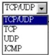
Protocol:
Choose the proper interface for this function. If you don't know how to select, simply use the default one, TCP/UDP.
Source IP Address/ Subnet Mask:
You have to type in the source IP address (ex: 192.168.1.50) and subnet mask (ex:255.255.255.0) for the application (ex: FTP, HTTP and so on) that you want to invoke the QoS traffic rule.
Source Port:
Except the IP address, you also have to enter the source port. Type in the source port for the traffic rule. The range is from 0 to 65535.
Destination IP Address/Subnet Mask:
You have to type in the destination IP address (ex: 192.168.1.254) and subnet mask (ex:255.255.255.0) for the application that
you want to invoke the QoS traffic rule.
Destination Port:
Type in the destination port for the traffic rule. The range is from 0 to 65535.
Traffic Priority:
There are three options – Low, Medium, and High that you can choose. It decides the order of each data transmitted through this device.
IP Precedence:
The number you choose here decides the type of the IP address processed. No change is the default setting.
IP type of Service:
The system provides some types of service for you to choose. The meaning of each type is the same as the denotation. The default one is No change.
Traffic Priority:
IP Precedence:
IP Type of Service:
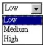
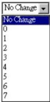
IP Type of Service:

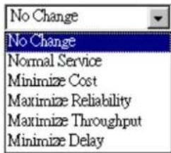
After you click Apply, the new QoS setting will be shown on the graphic as the right side. To delete the one you set, simply click the check button below Delete item and click Delete button.
Quality of Service
| Traffic Name | Priority | IP Precedence | IP IOS | 002.1P | Source IP | Destination IP | Delete | ||
| Address Netmask | Start Port End Port | Address Netmask | Start Port End Port | ||||||
| Number | Low | No Change | No Change | 192.168.1.25255.255.255.0 | 123321 | 192.168.1.100255.255.255.0 | 123321 | ||
Add Delete
Port Mapping
This page allows you to configure various port mapping groups which contains specific Internet connections and LAN ports. All the user data can be only transmitted and received among the interfaces in the groups that you specified in this page.
Port Mapping Configuration
This page allows you to configure various port mapping groups which contains specific Internet connections and LAN ports. The user data are only transmitted and received among the interfaces in the group.
NOTE: DHCP server and all routing/firewall functions are only available at the Default group.
| Group Name | Internet Connections | LAN Ports | Edit |
| Default | ppcoe_8_35_1 | Ethernet, USB, Wireless |
Add
Group Name:
Type in a name here as a group name. It must be unique. The word length must not be over the length of the field.
Available Interfaces:
The available interfaces (such as Ethernet, USB, wireless, etc.) will be displayed in the left side box. When you choose it and click Add, it will be transferred into the right side box of Grouped Interfaces. Yet, if you want to remove the interface from the current group, it will be returned back to the Default group (left side box) after you click Remove.
After finish the settings, click Apply.
Add New Port Mapping Group
Available interfaces can be LAN ports or Internet connections of ATM PUC bridge mode.
Group Name: The group name must be unique.
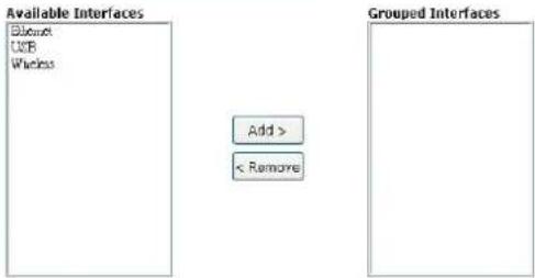
< Back Apply Selected interfaces will be removed from their existing groups and added to the new group. If you remove one interface from current group, this interface will be returned back to the Default group.
Wireless
The Wireless setting must match the other Wireless stations.
Basic
To set the basic configuration for the wireless features, please open Basic item from the Wireless menu.
Enable Wireless Network:
Click this check box to enable the wireless network function.
Hide Wireless Network:
Checking this box can hide the SSID of this access point. Then other people in the network cannot find the SSID of this device.
Wireless Network Name (SSID):
The system will detect the SSID of your router and displayed in this field for your reference.
The SSID is the identification characters of a router. The default words will be shown on this page. If you do not check the Hide Access Point item, the router will periodically broadcasts its SSID to allow the wireless clients within the range to recognize its presence. This can create a security hole since any wireless clients which got the broadcast might associate to your system. Please be noted that if you want to communicate, all wireless clients should use the same SSID with the router or access point.
Channel:
The frequency in which the radio links are about to be established. Select one channel that you want from the drop down list.
As an administrator of network, he/she must search which channels are available and then assign one available channel as the communication channel. All the other clients that want to transmission through this device should choose the same channel that you set in this field.
Transmission Mode:
It decides the mode of data transmission. Choose the one that you want to use from the drop-down menu. There are 802.11b only, 802.11g only and Mixed Mode provided here.
Wireless Basic Settings
This page allows you to configure basic features of your wireless network. You can enable or disable the wireless interface, hide the network from active scans, set the wireless network name (also known as SSID) and select the working channel.
Enable Wireless Network
Hide Wireless Network (Hidden SSID)
Wireless Network Name (SSID):
Channel:
Transmission Mode:
Transmission Rate:
Multicast Rate:
Turbo Mode
Afterburner:
Wireless User Isolation:
RTA1025W-cht
7
mixed mode
Auto
Auto
Disabled Enabled
Disabled Enabled
Off
Apply
Transmission Mode:
Transmission Rate:
Multicast Rate:
Turbo Mode:
Afterburner:
Wireless User Isolation:
Transmission Mode:
Transmission Rate:
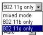
● Disabled C Enabled
● Disabled ○ Enabled
Off
mixed mode

Transmission Rate:
It decides the speed of data transmission. Choose any one of it by using the drop-down menu. This setting will change by the transmission mode that you set above. If you choose 802.11b only as the transmission mode, the transmission rate settings include 1, 2, 5.5, 11Mbit/s and auto. If you choose
802.11g, the transmission rate settings include 1, 2, 5.5,6,9, 11,12,18,24,36,48, 54Mbit/s and auto. If you choose mixed mode, only Auto is available.
Transmission Mode:
Transmission Rate:
Transmission Mode:
Transmission Rate:
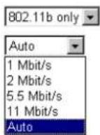

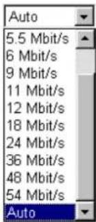
Multicast Rate:
When the traffics of the file are large, the condition of delay will be happened in some way, especially for transmitting multicast movie or service. You can use the default setting. If you want to speed up the rate, choose the one from the drop-down list. In addition, the selections for this item will be different according to the transmission mode that you choose on this page.
Turbo Mode:
When it is enabled, the data transmission will be faster for this router. Check Enabled to invoke this function for speeding up the transmission, or check Disabled to close this function.
Afterburner:
When it is enabled, the data transmission will be faster for the clients. Yet, the clients of this router must support 125Mbps throughput, then you can choose Enabled. Otherwise, choose Disabled.
Wireless User Isolation:
To make the communication between the clients, please choose Off. To cut the communication between the clients, please choose On.
Click Apply to invoke the settings.
Transmission Mode:
Transmission Rate:
Multicast Rate:
Transmission Mode:
Transmission Rate:
Multicast Rate:
Transmission Mode:
Transmission Rate:
Multicast Rate:
Wireless User Isolation:



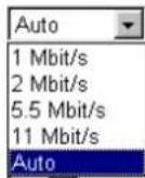


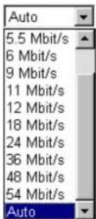
Security
To configure security features for the Wireless interface, please open Security item from Wireless menu. This web page offers four authentication protocols for you to secure your data while connecting to networks. There are four selections including None WPA, 802.1X, WPA, and WPA-PSK. Different item leads different web page settings. Please read the following information carefully.
For WPA Disabled
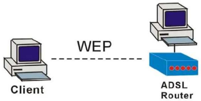
flowchart
graph LR
    A["Client"] -->|WEP| B["ADSL Router"]
Protected by WEP only
For Wireless Security Disabled
Wireless Security:
The Disabled item offers you the less protection for wireless communication. If you choose Disabled, the Encryption Keys will not be shown on this page.
Wireless Security
This page allows you to protect your wireless network by specifying WEP, 802.1x, or WPA wireless security. Before setting up security, ensure that your wireless adaptors support the same type of security. Most support WEP, but not all support WPA or 802.1x
Wireless Security: Disabled
Apply
For 64-Bit WEP
Wireless Security:
Select the WEP mode for the WEP key function. You can choose 64-bit or 128-bit for your necessity. If selected, data is encrypted using the key before being transmitted. For example, if you set 64-bit in this field, then the receiving station must be set to use 64 Bit Encryption, and have the same Key value too. Otherwise, it will not be able to decrypt the data. Please choose 64-Bit WEP for this page.
Authentication Type:
The Wireless IAD supports two authentication types: Open System and Shared key. This should be considered with the WEP (Wired Equivalent Privacy) mechanism.
Wireless Security
This page allows you to protect your wireless network by specifying WEP, 802.1x, or WPA wireless security. Before setting up security, ensure that your wireless adaptors support the same type of security. Most support WEP, but not all support WPA or 802.1x
Wireless Security: 64-bit WEP
Authentication Type: Open System
Encryption Keys
Enter 5 ASCII characters or 10 hexadecimal digits for 64-bit encryption keys.
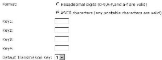

After enabling security and clicking Apply, you will lose the connection with your wireless ADSL router. You should now set-up security on your wireless adapters in order to re-establish the connection.
Open System means that it allows any client to authenticate and attempt to communicate with a bridge. The client can only communicate if its WEP keys match the router's WEP keys.
Shared Key means that a bridge or router will send an unencrypted text string to any client attempting to communicate with the router. The client requesting authentication encrypts the text and sends back to the router. Both unencrypted and encrypted can be monitored, yet it leaves the bridge open to attack from any intruder if he calculates the WEP key by comparing the text strings That is why shared key authentication can be less secure than open authentication.
Format:
Choose the typing method of encryption key. You have to click either Hexadecimal digits or ASCII characters and type the keys on the fields of Key 1 to Key 4.
Key 1 to 4:
Type the encryption key length and fill out WEP keys. For 64-bit WEP mode, the number you can type is that 5 characters or 10 hexadecimal digits.
Default Transmission Key:
Select one of network key that you set on the Key boxes as the default one.
After finished settings, click Apply for activation.
For 128-Bit WEP
Wireless Security: Select the WEP mode for the WEP key function. You can choose 64-bit or 128-bit for your necessity. If selected, data is encrypted using the key before being transmitted. For example, if you set 128-bit in this field, then the receiving station must be set to use 128 Bit Encryption, and have the same Key value too. Otherwise, it will not be able to decrypt the data. Please choose 128-Bit WEP for this page.
Authentication Type:
The Wireless IAD supports two authentication types: Open System and Shared key. This should be considered with the WEP (Wired Equivalent Privacy) mechanism.
Open System means that it allows any client to authenticate and attempt to communicate with a bridge. The client can only communicate if its WEP keys match the router's WEP keys.
Shared Key means that a bridge or router will send an unencrypted text string to any client attempting to communicate with the router. The client requesting authentication encrypts the
Wireless Security
This page allows you to protect your wireless network by specifying WEP, 802.1x, or WPA wireless security. Before setting up security, ensure that your wireless adaptors support the same type of security. Most support WEP, but not all support WPA or 802.1x
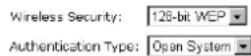
Encryption Keys
Enter 13 ASCII characters or 26 hexadecimal digits for 128-bit encryption keys
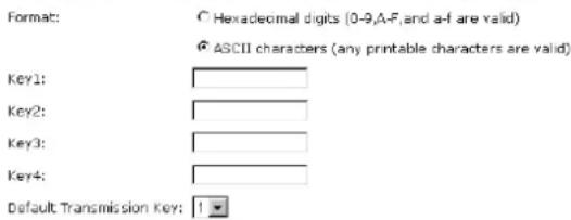
Apply After enabling security and clicking Apply, you will lose the connection with your wireless ADSL router. You should now set-up security on your wireless adapters in order to re-establish the connection.
text and sends back to the router. Both unencrypted and encrypted can be monitored, yet it leaves the bridge open to attack from any intruder if he calculates the WEP key by comparing the text strings That is why shared key authentication can be less secure than open authentication.
Format:
Choose the typing method of encryption key. You have to click either Hexadecimal digits or ASCII characters and type the keys on the fields of Key 1 to Key 4.
Key 1 to 4:
Type the encryption key length and fill out WEP keys. As for 128-bit WEP mode, the number you can type is that 13 characters or 26 hexadecimal digits.
Default Transmission Key:
Select one of network key that you set on the Key boxes as the default one.
After finished settings, click Apply for activation.
For 802.1X Wireless Network
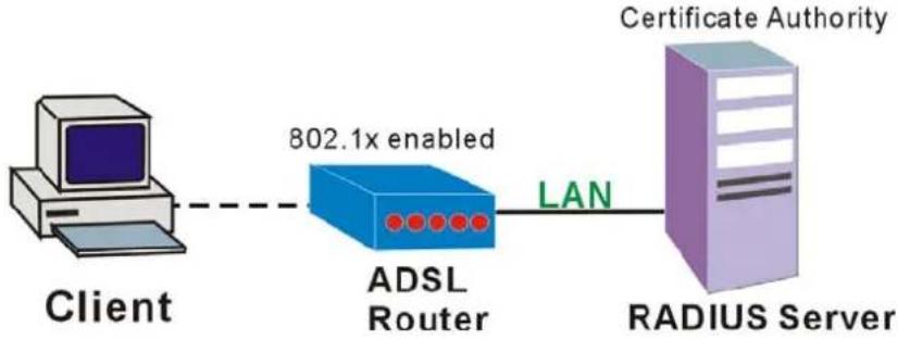
flowchart
graph LR
    A["Client"] -->|802.1x enabled| B["ADSL Router"]
    B -->|LAN| C["RADIUS Server"]
    D["Certificate Authority"] --> C
When a wireless client requests access to a network, it is required to be authenticated by a central authentication server (RADIUS Server). Only an authenticated user can be granted by the network access and thereby unauthorized is blocked.
Wireless Security:
Choose 802.1x as the authentication protocol, your data transmission between the router and the clients will be protected with the settings that you set in this web page.
RADIUS Server IP Address:
RADIUS Server is a protocol for carrying authentication, authorization, and configuration information between a Network Access Server which desires to authenticate its links and a shared Authentication Server. Please type in the II Address for the RADIUS Server.
RADIUS UDP Port:
Except for the IP address of the RADIUS Server, you have to enter the port number for the server. Port 1812 is the reserved RADIUS-authentication port described in RFC 2138. Earlier AP (RADIUS clients) use port 1945. The default value will be shown on this box. You can keep and use it.
RADIUS Share Secret:
A share secret is like a password, which is used between RADIUS Server and the specific AP (RADIUS client) to verify identity. Both RADIUS Server and the AP (RADIUS client) must be use the same shared secret for successful communication to occur. Type in the words for the share secret.
After finished settings, click Apply for activation.
Wireless Security
This page allows you to protect your wireless network by specifying WEP, 802.1x, or WPA wireless security. Before setting up security, ensure that your wireless adaptors support the same type of security. Most support WEP, but not all support WPA or 802.1x
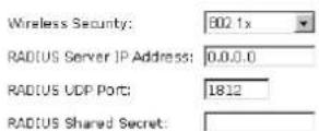

After enabling security and clicking Apply, you will lose the connection with your wireless ADSL router. You should now set-up security on your wireless adapters in order to re-establish the connection.
Example for Configuration 802.1x environment
You will need the following components for establishing an 802.1x environment in your network.
Windows 2000 Server: RADIUS server installed using "Internet Authentication Service". Certificate Services is installed
☐ AP (Router): It should be connected to Windows 2000 Advanced Server through the LAN port. The DHCP server for the router is used and 802.1x must be enabled.
☐ 802.1x client: A WLAN card supporting WEP is used.
□ Authentication Mechanism
For WPA (Wi-Fi Protected Access)
WiFi-Protected Access:
The WPA is suitable for enterprises. It must be used in conjunction with an authentication server such as RADIUS to provide centralized access control and management. It can provides stronger encryption and authentication solution than others WPA mode.
Data Encryption (WPA):
Select the data encryption for the WPA mode. There are three types that you can choose, TKIP, AES, TKIP+AES.
TKIP takes the original master key only as a starting point and derives its encryption keys mathematically from this master key. Then it regularly changes and rotates the encryption keys so that the same encryption key will be never used twice.
AES provides security between client workstations operating in ad hoc mode. It uses a mathematical ciphering algorithm that employs variable key sizes of 128, 192 or 256 bits.
TKIP+AES combines the features and functions of TKIP and AES.
WPA Group Rekey Interval:
Type in the time for the WPA group rekey interval. The unit is second.
RADIUS Server IP Address:
RADIUS Server is a protocol for carrying authentication, authorization, and configuration information between a Network Access Server which desires to authenticate its links and a shared Authentication Server. Please type in the IP Address for the RADIUS Server.
RADIUS UDP Port:
Except for the IP address of the RADIUS Server, you have to enter the port number for the server. Port 1812 is the reserved RADIUS-authentication port described in RFC 2138. Earlier RADIUS clients use port 1945. The default value will be shown on this box. You can keep and use it.
RADIUS Share Secret:
A share secret is like a password, which is used between IAS and the specific RADIUS client to verify identity. Both IAS and the RADIUS client must be use the same shared secret for successful communication to occur. Type in the words for the share secret.
After finished settings, click Apply for activation.
Wireless Security
This page allows you to protect your wireless network by specifying WEP, 802.1x, WPA, or WPA2 wireless security. Before setting up security, ensure that your wireless adaptors support the same type of security. Most support WEP, but not all support WPA, WPA2, or 802.1x.
| Wireless Security: | WPA |
| Data Encryption: | TKIP |
| WPA Group Relay Interval: | 0 seconds |
| RADIUS Server IP Address: | 0.0.0.0 |
| RADIUS UDP Port: | 1812 |
| RADIUS Shared Secret: |

After enabling security and clicking Apply, you will lose the connection with your wireless ADSL router. You should now set-up security on your wireless adapters in order to re-establish the connection.
For WPA-PSK/ WPA2-PSK/ Mixed WPA-PSK
WiFi-Protected Access:
WPA-PSK is useful for small places such as home environment without having authentication servers. It allows the use of manually-entered keys or passwords and is designed to be easy to set up for home users.
Format:
Choose the typing method of encryption key. You have to click either Hexadecimal digits or ASCII characters and type the keys on the field of Pre-Share Key.
Pre-Share Key:
Please type with the key between 8 and 63 characters, or 64 hexadecimal digits. Only the devices with a matching key that you set here can join this network.
WPA Group Rekey Interval:
Type in the time for the WAP group rekey interval. The unit is second.
Data Encryption (WPA):
Select the data encryption for the WPA mode. There are three types that you can choose, TKIP, AES, TKIP+AES.
TKIP takes the original master key only as a starting point and derives its encryption keys mathematically from this master key. Then it regularly changes and rotates the encryption keys so that the same encryption key will be never used twice.
AES provides security between client workstations operating in ad hoc mode. It uses a mathematical ciphering algorithm that employs variable key sizes of 128, 192 or 256 bits.
TKIP+AES combines the features and functions of TKIP and AES.
After finished settings, click Apply for activation.
Wireless Security
This page allows you to protect your wireless network by specifying WEP, 802.1x, or WPA wireless security. Before setting up security, ensure that your wireless adaptors support the same type of security. Most support WEP, but not all support WPA or 802.1x
Wireless Security: WPA-PSK
WPA Pre-Shared Key
Enter the key to be between 8 and 63 ASCII characters, or 64 hexadecimal digits
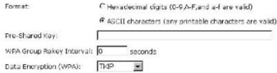
Apply After enabling security and clicking Apply, you will lose the connection with your wireless ADSL router. You should now set-up security on your wireless adapters in order to re-establish the connection.
For WPA-2 (Wi-Fi Protected Access) / For Mixed WPA2/ WPA
WiFi-Protected Access:
The WPA2 is suitable for enterprises. It must be used in conjunction with an authentication server such as RADIUS to provide centralized access control and management. It can provides stronger encryption and authentication solution than others WPA mode.
Data Encryption (WPA):
Select the data encryption for the WPA mode. There are three types that you can choose, TKIP, AES, TKIP+AES.
Wireless Security
This page allows you to protect your wireless network by specifying WEP, 802.1x, WPA, or WPA2 wireless security. Before setting up security, ensure that your wireless adaptors support the same type of security. Most support WEP, but not all support WPA, WPA2, or 802.1x.
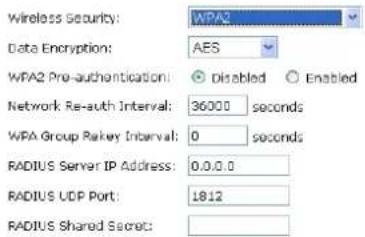
TKIP takes the original master key only as a starting point and derives its encryption keys mathematically from this master key. Then it regularly changes and rotates the encryption keys so that the same encryption key will be never used twice.
AES provides security between client workstations operating in ad hoc mode. It uses a mathematical ciphering algorithm that employs variable key sizes of 128, 192 or 256 bits.
TKIP+AES combines the features and functions of TKIP and AES.

After enabling security and clicking Apply, you will lose the connection with your wireless ADSL router. You should now set-up security on your wireless adapters in order to re-establish the connection.
WPA2 Pre-authentication:
The wireless client that has associated with an AP (A) can do the authentication with another AP (B) in advance. If the client roams to AP(B), it can associate with AP(B) quickly. Please click Enabled to inactivate this function.
Network Re-auth Interval:
When a wireless client has associated with the number greater than the setting here, it would be disconnected and the authentication will be executed again. The default value is 36000.
WPA Group Rekey Interval:
Type in the time for the WPA group rekey interval. The unit is second.
RADIUS Server IP Address:
RADIUS Server is a protocol for carrying authentication, authorization, and configuration information between a Network Access Server which desires to authenticate its links and a shared Authentication Server. Please type in the IP Address for the RADIUS Server.
RADIUS UDP Port:
Except for the IP address of the RADIUS Server, you have to enter the port number for the server. Port 1812 is the reserved
RADIUS-authentication port described in RFC 2138. Earlier RADIUS clients use port 1945. The default value will be shown on this box. You can keep and use it.
RADIUS Share Secret:
A share secret is like a password, which is used between IAS and the specific RADIUS client to verify identity. Both IAS and the RADIUS client must be use the same shared secret for successful communication to occur. Type in the words for the share secret.
After finished settings, click Apply for activation.
Access Controls
The web page allows you to enable the wireless MAC control configuration.
Access Control:
Click Off to disable this function. Click On in Allow mode to make any wireless MAC address can be linked to. And click On in Deny mode to disturb any wireless MAC address to be linked to.
View Access Control List:
Click this button to view the wireless access control list and to add a new access control.
Wireless MAC Access Control
This page lets you to specify the wireless adaptors that are allowed to connect to your ADSL router. This offers additional protection against unwanted connections. Click "Apply" to configure the wireless access control mode.
Access Control:
On in Allow mode (Only those wireless adaptors listed in the access control table are allowed to connect to your ADSL router, others are denied.)
On in Deny mode (Only those wireless adaptors listed in the access control table cannot connect to your ADSL router, others are allowed.)

The Wireless Access Control List dialog allows you to add a new MAC address and view current MAC address that you had added.
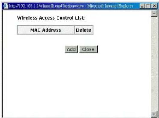
To add a new MAC address to your wireless MAC address filters, click on the Add button from the Wireless Access Control List dialog to show next page.
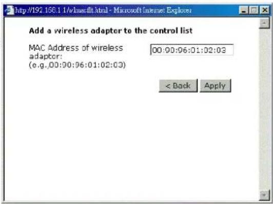
MAC Address of Wireless:
You have to type in the MAC Address that you want it to be linked to your router. And click Apply.
The result of adding a new MAC address will be shown the example as the right picture.
If you want to delete the added MAC address, simple click the delete button (like a trash can), a dialog box will be shown to ask you. Click Yes, then the new one will be erased.
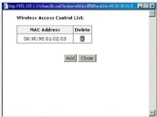
Repeater
The web page allows you to configure the wireless distribution system for the wireless network.
AP Mode:
Choose either one of the selection as the AP mode.
Search Other Repeaters:
Click the Scan Now button to scan search other repeater in the wireless network. The result will be shown under below.
Click Apply to invoke the wireless repeater options.
If you click Manual as the Search Other Repeaters, you will need to type the MAC address for wireless repeaters in the boxes of MAC Address of Remote Wireless Repeaters.
Wireless Repeater
This page allows you to configure wireless repeater feature (also known as Wireless Distribution System) for your wireless network. Click "Apply" to configure the wireless repeater options.
AP Mode: C Access Point and Wireless Repeater Function C Wireless Repeater only
Search Other Repeaters: © Auto © Manual Scan Now
CH SSID MAC Address Transmission Mode Select
Apply
Wireless Repeater
This page allows you to configure wireless repeater feature (also known as Wireless Distribution System) for your wireless network. Click "Apply" to configure the wireless repeater options.
AP Mode: ☐ Access Point and Wireless Repeater Function ☐ Wireless Repeater only
Search Other Repeaters: © Auto © Manual
MAC Address of Remote Wireless Repeaters: (e.g.,00:90:96:01:02:03)
Apply
The right picture shows an example of executing the function of wireless repeater.
When you finish settings, please click Apply to invoke them actually.
Wireless Repeater
This page allows you to configure wireless repeater feature (also known as Wireless Distribution System) for your wireless network. Click "Apply" to configure the wireless repeater options.
AP Mode: ☑ Access Point and Wireless Repeater Function ○ Wireless Repeater only
Search Other Repeaters: © Auto © Manual Scan Now
| CH | SSID | MAC Address | Transmission Mode | Select |
| 12 | EMI | 00:90:96:AF:47:75 | 802.11g | |
| 1 | ADSL_D200 | 00:90:96:FA:76:82 | 802.11g | |
| 2 | Askey-WLan | 00:90:96:28:CC:72 | 802.11h | |
| 3 | roy | 00:90:96:67:8E:99 | 802.11g | |
| 6 | EMI-2 | 00:90:96:52:2D:74 | 802.11g |
Apply
Management
Diagnostics
To check the link status for the network and your computer, a diagnostic test can guide you to detect the network problem. The testing items are listed and accomplished one by one. If the previous one is failed, than the items below that failed one will be failed too. Use this diagnostic test to detect the connectivity mistakes whenever you happen to the linked problem.
For the item which passes through the diagnostics, a PASS word will be shown on the right side of that item.
If not, a Fail word will be there.
N/A means that item is not necessary for the system to test.
Diagnostic Tests
This DSL Router is capable of testing your DSL connection. The individual tests are listed below. If a test displays a fail status, click "Run Diagnostic tests" again to make sure the fail status is consistent. If the test continues to fail, click "Help" and follows the troubleshooting procedures.
Select the Internet Connection: pppoa_8_35
Run Diagnostic Tests
Test the connection to your local network
Test your Ethernet Connection: PASS Help
Test the connection to your DSL service provider
| Test ADSL Synchronization: | FAIL | Help |
| Test ATM OAM F5 segment ping: | N/A | Help |
| Test ATM OAM F5 end-to-end ping: | N/A | Help |
| Test ATM OAM F4 segment ping: | N/A | Help |
| Test ATM OAM F4 end-to-end ping: | N/A | Help |
| Test the connection to your Internet service provider | ||
| Test PPP server connection: | N/A | Help |
| Test authentication with ISP: | N/A | Help |
| Test the assigned IP address: | N/A | Help |
| Ping default gateway: | N/A | Help |
| Ping primary Domain Name Server: | N/A | Help |
The Help link lets you know what the result (Pass, Down, Fail) represents for. In this page you still can rerun diagnostic test at any time.
ADSL Synchronization Test
| Pass: | Indicates that the DSL router has detected a DSL signal from the telephone company. A solid DSL LED on the router also indicates the detection of a DSL signal from the telephone company. |
| Fail: | Indicates that the DSL router does not detect a signal from the telephone company's DSL network. The DSL LED will continue to flash green. |
If the test fails, follow the troubleshooting procedures listed below and rerun the diagnostics tests by clicking 'Rerun Diagnostic Tests' at the bottom of this page. If all the tests pass, close and restart your Web browser to access the Internet.
Troubleshooting:
- Make sure your phone line is plugged into the router.
- After turning on your DSL router, wait for at least one minute to establish a connection. Run the diagnostic tests again by clicking "Perun Diagnostic Tests" at the bottom of this page.
- Make sure there is no DSL micro filter on the phone cord connecting the DSL router to the wall jack.
- Make sure you are using the phone cord that was supplied with your DSL router or another similar phone cord with four copper wires visible in the plug
- If your DSL has been functioning properly for a long period of time and you suddenly are experiencing this problem, there may be a problem with the DSL network. You may need to wait from 30 minutes to a couple of hours, and if you still do not have a solid DSL LED on your router, call Technical Support.
- Turn off the power to the DSL router, wait 10 seconds and turn it back on. Wait at least one minute and if the DSL LED on the router remains a solid color, close your Web browser and restart it.
Renun Diagnostic Tests
Contact ISP Technical Support if you have tried all of the above and still are experiencing a fail condition.
Admin Account
This page allows you to type in the password for accessing into your DSL Router.
For the Admin Account, the default setting for user password is admin. If you want to change the username and the password, please retype the new password in the Confirm field for confirmation. Then click Apply.
Admin Account
Admin account has unrestricted access to change and view configuration of your DSL Router.
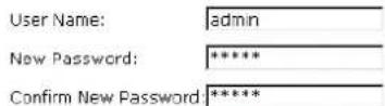
Apply
Remote Access
There are four interfaces for the remote access. Please choose one of them if you want to enable the remote access control.
Select the Internet Connection:
Select one connection item from the drop down list to enable the function.
Web Browser:
Choose this box if you want to have remote control through HTTP. The default port number will be shown in the box. Modify this number whenever you want.
Telnet:
Choose this box if you want to have remote control through telnet.
FTP:
Choose this box if you want to have remote control through FTP.
SNMP:
Choose this box if you want to have remote control through SNMP agent.
TFTP:
Choose this box if you want to have remote control through TFTP.
Secure Shell (SSH):
Choose this box if you want to have remote control through SSH.
Ping:
Choose this box if you want to have remote control through ping command under DOS prompt.
Remote Access Control
Enable remote access to let an expert, e.g. helpdesk, configure your ADSL router remotely.

To allow remote access to your router via
Γ Web Browser

Telnet FTP
SNMP TFTP
Secure Shell (SSH) PING
If enabling remote access to your router via PING, all Internet hosts can ping to your router.

Interntet Time
The router's clock must synchronize with global Internet's time. The time you set in the screen will be adapted to system log.
Update:
Click this button to refresh the current time.
Set Time by:
The default setting is Manual. If you select Time Server, you don't need to type in the time setting manually. The system will set automatically.
Time:
Set the start time by typing the year, the month, the day, the hour, and the date to help the router perform tasks.
Timezone:
Choose the time zone of your country where you are going to use the router.
Apply:
Save the data on the screen and apply the data after restarting the router.
Internet Time
To synchronize your router with other network devices, you can set its time manually or with an Internet time server.
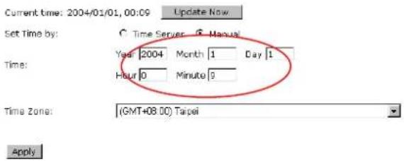
Internet Time
To synchronize your router with other network devices, you can set its time manually or with an Internet time server.
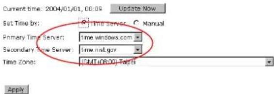
System Log
As shown in the web page, you can view the system log and configure system log whenever you want.
System Log
The System Log dialog allows you to view the System Log and configure the System Log options.
Click "View System Log" to view the System Log.
Click "Configure System Log" to configure the System Log options.
View System Log Configure System Log
Configure System Log
After you click Configure System Log, the following screen will appear. You can enable or disable the log function, choose log level, display level and proper mode as you like. Then click Apply.
System Log Configuration
This dialog allows you to configure System Log settings. All events greater than or equal to the selected level will be logged or displayed. If the selected mode is "Remote" or "Both" events will be sent to the specified UDP port of the specified log server.
Select the desired values and click "Apply" to configure the system log options.
Log: © Disabled © Enabled
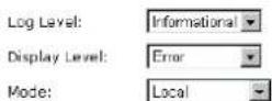
Apply
There are 8 types for log level and display level for your choose. The default is Debugging.
Log Level:
Display Level:
Mode:
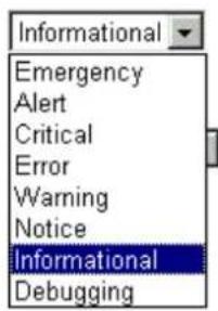
Apply
The mode selection includes Local, Remote and Both. The default one is Local. If you choose Remote or Both, all the events will be sent to the specified UDP port of the specified log server.
Log Level:
Display Level:
Mode:

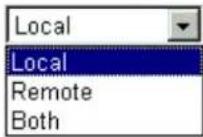
Apply
Viewing System Log
For viewing the system log, please click the View System Log button.
System Log
The System Log dialog allows you to view the System Log and configure the System Log options.
Click "View System Log" to view the System Log.
Click "Configure System Log" to configure the System Log options.

The screen will be shown immediately for your reference.
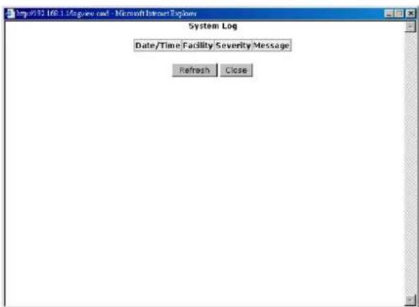
SNMP Setting
The SNMP, the abbreviation of Simple Network Management Protocol, is used to refer to a collection of specifications for network management that include the protocol itself, the definition of data structures and associated concepts.
A management station performs the monitoring function by retrieving the value of MIB objects. The management station and agents are linked by a network management protocol that is SNMP. The SNMP includes three key capabilities, get, set and trap. A single management station can handle many agents as long as SNMP remains relatively “simple”, so the number can be high (hundreds or so).
The following picture is the typical configuration of protocols for SNMP. As for a stand-alone management station, a manager process controls access to a central MIB at the management station and provides an interface to the network manager. The manager process achieves network management by using SNMP, which will be implemented on top of the UDP, IP and the relevant network-dependent protocols (e.g., Ethernet).
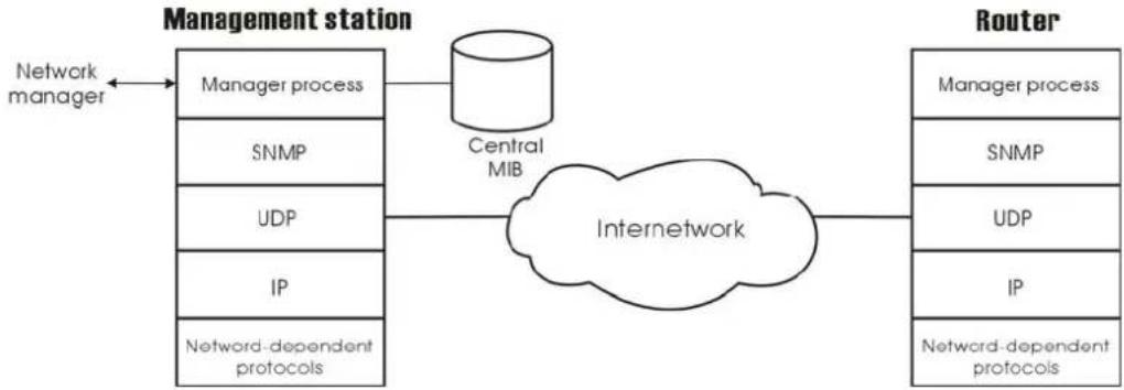
flowchart
graph LR
    A["Network manager"] --> B["Management station"]
    B --> C["Manager process"]
    B --> D["SNMP"]
    B --> E["UDP"]
    B --> F["IP"]
    B --> G["Network-dependent protocols"]
    C --> H["Central MIB"]
    H --> I["Internetwork"]
    I --> J["Router"]
    J --> K["Manager process"]
    J --> L["SNMP"]
    J --> M["UDP"]
    J --> N["IP"]
    J --> O["Network-dependent protocols"]
For an agent device that supports other applications, such as FTP, both TCP and UDP are required. An agent may issue a trap message in response to an event that effects the MIB and the underlying managed resources.
Note: There are no ongoing connections are maintained between a management station and its agents. Instead, each exchange is a separate transaction between a management station and an agent.
Each agent is responsible for notifying the management station of any unusual event; for example, if the agent crashes and is rebooted, a link fails or an overload condition as defined by the packet load crosses some threshold. These events are communicated in SNMP messages known as traps.
Please select the SNMP menu from Management. The dialog will appear.
SNMP Agent:
Choose Disable to close this function; choose Enabled to open this function.
Read Community:
The default setting is public, please type in the data that your ISP provided.
Write Community:
The default setting is private, please type in the data that your ISP provided.
Enable TRAP Service:
Check this box to enable this function, otherwise uncheck this box to disable this function.
TRAP Manager IP:
Type in an IP address as the remote workstation. If there is any abnormal condition happened, you can advice remote
SNMP Configuration
Simple Network Management Protocol (SNMP) allows a management application to retrieve statistics and status from the SNMP agent in this device.
Select the desired values and click "Apply" to configure the SNMP options.
SNMP Agent
● Disabled C Enabled
Read Community
public
Write Community
private

Enable Trap Service
Trap Manager IP
0.0.0.0
Apply
workstation by way of SNMP agent.
Backup Config
To backup your configuration for the router to your computer, you can use Backup Config web page to save the settings.
And when you want to restore the settings in the future, simply open Backup Config web page and use Browse button to locate the file and click Restore.
Backup Configuration
Use to save your DSL Router's current settings into the computer.
Backup
Restore Configuration
Use to reset your DSL Router with settings previously saved on the computer.
Backup File: 浏览
Restore
Update Firmware
If you have to or want to update the firmware for this router, you can open the update software web page and choose the correct file by pressing Browse. Then click the Update Software button. The system will execute the update procedure automatically. When it is finished, the system will tell you the update is successfully.
Reset Router
To make effect the settings that you set for this router, please open the Reset Router web page and click the Reboot button to invoke all settings.
Update Firmware
Step 1: Obtain an updated firmware image file from your ISP.
Step 2: Enter the path to the image file location in the box below or click "Browse" to locate the image file.
Step 3: Click "Update Firmware" once to upload the new image file.
Current Firmware Version:
2.21.05.06_A2pB018c1.d16d
New Firmware File Name:
浏览
Update Firmware
The update process takes about 2 minutes to complete, then your ADSL router will reboot.
Reset Router
This page allows you to restart your ADSL router after changing settings that require rebooting. It also allows you to reset all settings to factory default settings if you have problems with your current configuration.
☐ Reset to factory default settings
Reboot After clicking "Reboot", please wait for 2 minutes to let the system reboot.
You can restore your web pages default settings. Simply check Reset to factory default settings and click Reboot.
Restore Factory Default Settings
The DSL Router configuration has been restored to factory default settings and the router is rebooting.
Close the DSL Router Configuration window and wait for 2 minutes before reopening your web browser. If necessary, reconfigure your PC's IP address to match your new configuration.
UPnP for XP
Universal plug and play (UPnP) is an architecture for pervasive peer to peer network connectivity of intelligent appliances and PCs of all form factors. It is designed to bring easy-to-use, flexible, standards-based connectivity to ad-hoc or unmanaged networks whether in the home, in a small business, public spaces, or attached to the Internet.
Only Windows XP supports UPnP function.
Please follow the steps below for installing UPnP components.
-
Click on the Start menu, point to Settings and click on Control Panel.
-
Select Add or Remove Programs > Add/Remove Windows Components to open Windows Components Wizard dialog box
-
Select Network Services and click Details. Click the Universal Plug and Play check box.
-
Click Ok. The system will install UPnP components automatically
-
After finishing the installation, go to My Network Places. You will find an icon (e.g., SL-XXX) for UPnP function.
-
Double click on the icon, the ADSL router will open another web page with port for UPnP function. The IE address will be changed as shown as the graphic.
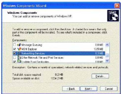
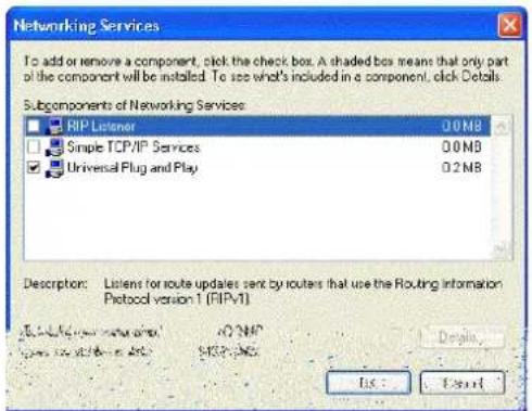
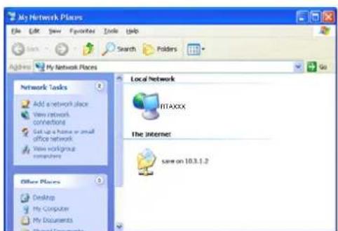
- Now, the NAT traversal function will be provided. The ADSL router will create a new virtual server automatically for mapping while the router detecting the computer running some Internet applications.
Chapter 5: Troubleshooting
If the suggested solutions in this section do not resolve your issue, contact your system administrator or Internet service provider.
Problems with LAN
PCs on the LAN cannot get IP addresses from the ADSL Router.
The chances are that the interface used as DHCP server is modified and the client PCs do not renew IP addresses.
If your DHCP server is enabled on Private IP Address previously and you modify the interface to Public IP Address, the client PCs should renew IP addresses.
The PC on the LAN cannot access the Web page of the ADSL Router.
Check that your PC is on the same subnet with the ADSL Router.
The virtual server can't be access after setting virtual server.
Check the filter rule of the port that virtual server service setting for example, the virtual server service set FTP 21 you need update the filter rule of the ftp 21 Direction setting: Choose filter the packets that incoming action (In Bound) are Allow on the interface.
Problems with WAN
You cannot access the Internet.
☐ Check the physical connection between the ADSL Router and the LAN.
If the LAN LED on the front panel is off or keeps blinking, there may be problem on the cable connecting to the ADSL Router.
At the DOS prompt, ping the IP address of the ADSL Router, e.g., ping 192.168.1.1. If the following response occurs:
Relay from 192.168.1.1 bytes=32 time=100ms TTL=253
Then the connection between the ADSL Router and the network is OK.
If you get a failed ping with the response of:
Request time out
Then the connection is fail. Check the cable between the ADSL Router and the network.
☐ Check the DNS setting of the ADSL Router.
At the DOS prompt, ping the IP address of the DNS provided by your ISP. For example, if your DNS IP is 168.95.1.1, then ping 168.95.1.1. If the following response occurs:
Relay from 168.95.1.1 bytes=32 time=100ms TTL=253
Then the connection to the DNS is OK.
If you get a failed ping with the response of:
Request time out
Then the DNS is not reachable. Check your DNS setting on the ADSL Router.
Problems with Upgrading
The following lists the error messages that you may see during upgrading and the action to take.
☐ Error: All the ADSL LEDs light up and cannot light off as usual.
Possible cause: When users execute firmware upgrade and save settings to the router, the power for the router is lost for some unknown reasons, the normal web page for the router might be damaged. After power on your router, the LEDs might not work normally.
Boot Loader, version 1.0.37-5.5.05
This device is currently running on the boot loader.
Update Firmware
Step 1: Obtain an updated firmware image file from your ISP.
Step 2: Enter the path to the image file location in the box below or click "Browse" to locate the image file.
Step 3: Click "Update Firmware" once to upload the new image file.
NOTE: The update process takes about 2 minutes to complete, and your DSL Router will reboot.
New Firmware File Name:
Browse.
Update Firmware
Action: Use the browser to connect to the router for executing image upgrade.
☐ Error Message: Image uploading failed. The selected file contains an illegal image.
Possible cause: The firmware file format is invalid.
Action: Check the file format is correct, otherwise download a firmware file with correct format.
☐ Error Message: Image uploading failed. The system is out of memory.
Possible cause: It may be caused by the lack of memory.
Action: Reboot your ADSL Router and perform the upgrade task again.
☐ Error Message: Image uploading failed. No image file was selected.
Possible cause: You did not select a file correctly.
Action: Download a compatible firmware from the web.
Chapter 6: Glossary
ARP (Address Resolution Protocol)
ARP is a TCP/IP protocol for mapping an IP address to a physical machine address that is recognized in the local network, such as an Ethernet address.
A host wishing to obtain a physical address broadcasts an ARP request onto the TCP/IP network. The host on the network that has the IP address in the request then replies with its physical hardware address.
Inverse ARP (In-ARP), on the other hand, is used by a host to discover its IP address. In this case, the host broadcasts its physical address and a RARP server replies with the host's IP address.
DHCP (Dynamic Host Configuration Protocol)
When operates as a DHCP server, the ADSL Router assign IP addresses to the client PCs on the LAN. The client PCs “leases” these Private IP addresses for a user-defined amount of time. After the lease time expires, the private IP address is made available for assigning to other network devices.
The DHCP IP address can be a single, fixed public IP address, an ISP assigned public IP address, or a private IP address.
If you enable DHCP server on a private IP address, a public IP address will have to be assigned to the NAT IP address, and NAT has to be enabled so that the DHCP IP address can be translated into a public IP address. By this, the client PCs are able to access the Internet.
LAN (Local Area Network) & WAN (Wide Area Network)
A LAN is a computer network limited to the immediate area, usually the same building or floor of a building. A WAN, on the other hand, is an outside connection to another network or the Internet.
The Ethernet side of the ADSL Router is called the LAN port. It is a twisted-pair Ethernet 10Base-T interface. A hub can be connected to the LAN port. More than one computers, such as server or printer, can be connected through this hub to the ADSL Router and composes a LAN.
The DSL port of the ADSL Router composes the WAN interface, which supports PPP or RFC 1483 connecting to another remote DSL device.
NAT (Network Address Translation) IP Address
NAT is an Internet standard that translates a private IP within one network to a public IP address, either a static or dynamic one. NAT provides a type of firewall by hiding internal IP addresses. It also enables a company to use more internal IP addresses.
If the IP addresses given by your ISP are not enough for each PC on the LAN and the ADSL Router, you need to use NAT. With NAT, you make up a private IP network for the LAN and assign an IP address from that network to each PC. One of some public addresses is
configured and mapped to a private workstation address when accesses are made through the gateway to a public network.
For example, the ADSL Router is assigned with the public IP address of 168.111.2.1. With NAT enabled, it creates a Virtual LAN. Each PC on the Virtual LAN is assigned with a private IP address with default value of 192.168.1.2 to 192.168.2.254. These PCs are not accessible by the outside world but they can communicate with the outside world through the public IP 168.111.2.1.
Private IP Address
Private IP addresses are also LAN IP addresses, but are considered “illegal” IP addresses to the Internet. They are private to an enterprise while still permitting full network layer connectivity between all hosts inside an enterprise as well as all public hosts of different enterprises.
The ADSL Router uses private IP addresses by assigning them to the LAN that cannot be directly accessed by the Internet or remote server. To access the Internet, private network should have an agent to translate the private IP address to public IP address.
Public IP Address
Public IP addresses are LAN IP addresses that can be considered “legal” for the Internet, because they can be recognized and accessed by any device on the other side of the DSL connection. In most cases they are allocated by your ISP.
If you are given a range of fixed IP addresses, then one can be assigned to the router and the others to network devices on the LAN, such as computer workstations, ftp servers, and web servers.
PVC (Permanent Virtual Circuit)
A PVC is a logical point-to-point circuit between customer sites. PVCs are low-delay circuits because routing decisions do not need to be made along the way. Permanent means that the circuit is preprogrammed by the carrier as a path through the network. It does not need to be set up or turned down for each session.
RIP (Routing Information Protocol)
RIP is a routing protocol that uses the distance-vector routing algorithms to calculate least-hops routes to a destination. It is used on the Internet and is common in the NetWare environment. It exchanges routing information with other routers. It includes V1, V2 and V1&V2, which controls the sending and receiving of RIP packets over Ethernet.
UDP (User Datagram Protocol)
UDP is a connectionless transport service that dispenses with the reliability services provided by TCP. UDP gives applications a direct interface with IP and the ability to address a particular application process running on a host via a port number without setting up a connection session.
Virtual Server
You can designate virtual servers, e.g., a FTP, web, telnet or mail server, on your local network and make them accessible to the outside world. A virtual server means that it is not a dedicated server -- that is, the entire computer is not dedicated to running on the public network but in the private network.
VPI (Virtual Path Identifier) & VCI (Virtual Channel Identifier)
A VPI is a 8-bit field while VCI is a 16-bit field in the ATM cell header. A VPI identifies a link formed by a virtual path and a VCI identifies a channel within a virtual path. In this way,
the cells belonging to the same connection can be distinguished. A unique and separate VPI/VCI identifier is assigned in advance to indicate which type of cell is following, unassigned cells, physical layer OAM cells, metasignaling channel or a generic broadcast signaling channel. Your ISP should supply you with the values.
Appendix A: Specifications
| Interface | One RJ-11 port for ADSL connectionFour RJ-45 ports for IEEE 802.3/802.3u 10/100 Base- T auto-sensing and auto-crossover Ethernet connectionOne USB client port compliant to USB 1.1On-board wireless LAN module for IEEE 802.11g (2.4 GHz) wireless LAN connectionOne hidden reset button for restoring to factory default settings |
| Regulatory Approvals and Compliance | EMI: FCC part 15 Class B, CEImmunity: FCC part 68 Class BSafety: UL, CB, LVD |
| Power Requirement and Operation Environment Requirement | Power Adaptor: Input 110 ± 10 or 230 ± 10 VAC;Output 12 VAC, 1APower Consumption: less than 10 WattAmbient Temperature: 0 to 40^ (32 to 96^ )Relative Humidity: 20% to 90% (non-condensing) |
| Physical Dimensions | 190mm(L) × 130mm(W) × 40mm(H) Weight: 350g |
Appendix B: Server Setup for 802.1x Client
Getting Client Certificate
-
Please connect the client to a network that doesn't require port authentictaion.
-
Open up Microsoft Explorer in Windows XP, and go to http://
/certsrv. -
Authenticate to the server using your account that you created at the end of the server setup. (e.g. 123) and click OK. A dialog box might appear for you to choose.
-
Make sure that Request a certificate is selected, and click Next.
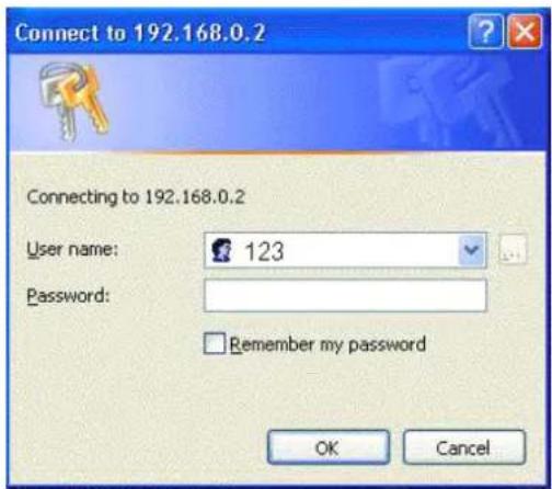
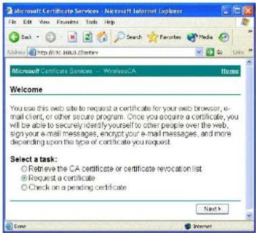
- Make sure that User certificate request: User Certificate is selected, and click Next.
- Click Submit in this dialog.
- Now, you'll see status messages on the screen, then your certificate will be returned to you. Click Install this certificate.
- You'll receive a confirmation message about accepting the certificate, click Yes
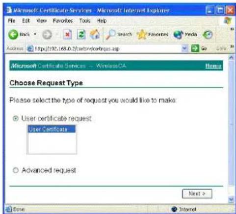
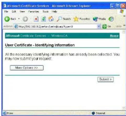
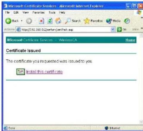
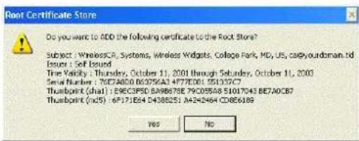
Enable 802.1x authentication and Encryption for wireless card
- Open up the properties for your wireless connection, either by right-click on My Network Places on the desktop, select Properties, or Open up the Control Panel, select Network Connections (located under Network and Internet Connections if in Category View)
- Right click on the Wireless Network Connection, and select Properties.
-
Select the Authentication Tab, and ensure that Enable network access control using IEEE 802.1X is selected, and Smart Card or other Certificate is selected from the EAP type.
-
Click on the Wireless Networks tab.
-
Select the wireless network on which you want to enable dynamic WEP from under Available Networks, and select Configure.
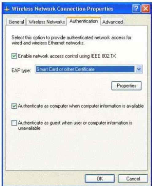
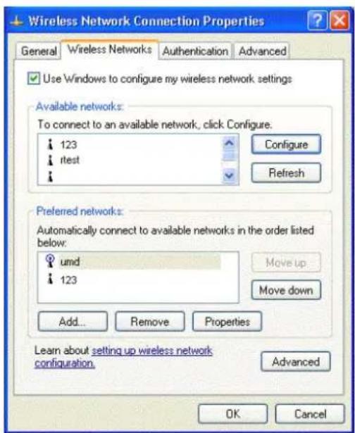
- Select Data encryption (WEP enabled), and ensure The key is provided for me automatically is also selected.
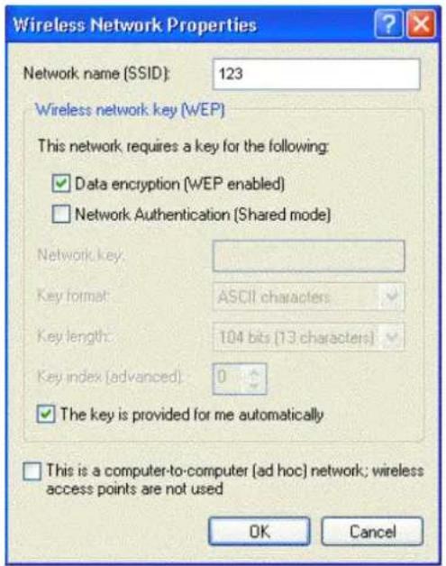
- Now you're ready to configure your router (AP) with 802.1x authentication.
Appendix C: WEEE – B2C

natural_image
Symbol of a trash bin with crossed lines indicating no waste, and a solid black rectangle below (no text or labels)All electrical and electronic products should be disposed of separately from the municipal waste stream via designated collection facilities appointed by the government or the local authorities.
The correct disposal and separate collection of your old appliance will help prevent potential negative consequences for the environment and human health. It is a precondition for reuse and recycling of used electrical and electronic equipment.
For more detailed information about disposal of your old appliance, please contact your city office, waste disposal service, the shop where you purchased the product or your SIEMENS partner.
The statements quoted above are only fully valid for equipment which is installed in the countries of the European Union and is covered by the directive 2002/96/EC.
Countries outside the European Union may have other regulations regarding the disposal of electrical and electronic equipment.
- SL2-141/SL2-141-I ADSL Router
- User's Manual
- Safety Notes
- For Installation
- For Using
- For Service
- Warning
- Caution
- FCC
- FCC Class B Notice
- IC Statement
- ICES-003 Class B Notice - Avis NMB-003, Classe B
- Features
- ADSL Compliance
- ADSL2 Compliance
- ADSL2+ Compliance
- Wireless LAN Compliance Features
- ATM Features
- Bridging Features
- Routing Features
- Security Features
- Configuration and Management
- Unpacking
- Subscription for ADSL Service
- Chapter 1: Overview
- Physical Outlook
- Front Panel
- LED Indicators
- Rear Panel
- Chapter 2: System Requirement and Installation
- System Requirement
- Choosing a place for the ADSL Router
- Connecting the ADSL Router
- Install the USB Driver
- For Windows ME
- For Windows 2000
- For Windows XP
- For Windows Vista
- Press System.
- Click Device Manager.
- Confirm that the Siemens ADSL Router USB Remote NDIS Device (BCM63xx Based) is
- Uninstall the USB Driver
- Click Device Manager.
- ⑤ Right click Askey ADSL Router USB Remote NDIS Device on the Network adapters list, and press Uninstall.
- ⑥ Click OK when the Confirm Uninstall window appears.
- Setting TCP/IP
- For Windows 98
- For Windows NT
- Configure PC to get IP address from DHCP
- Windows Vista
- Renew IP Address on Client PC
- For Windows 98ME
- Note:
- Chapter 3: Connecting and Accessing Internet
- PPP over ATM (PPPoA) Mode
- Description:
- Configuration:
- Numbered IP over ATM (IPoA)
- Numbered IP over ATM (IPoA) + NAT
- Unnumbered IP over ATM (IPoA)
- Unnumbered IP over ATM (IPoA) + NAT
- Bridge Mode
- Chapter 4: Web Configuration
- Using Web-Based Manager
- Outline of Web Manager
- To Have the New Settings Take Effect
- Language
- Quick Start
- Connect to Internet
- Quick Setup
- VCI (Virtual Channel Identifier):
- Connection Type
- Configure Internet Connection - Connection Type
- PPP over ATM/ PPP over Ethernet
- Configure Internet Connection - WAN IP Settings
- PPP Username:
- PPP Password:
- Always On:
- Dial on Demand:
- Manually Connect:
- Primary IP Address:
- Subnet Mask:
- Configure the second IP Address and Subnet Mask for LAN interface:
- Secondary IP Address:
- MTU:
- DHCP Server On:
- Start IP Address:
- End IP Address:
- Leased Time:
- DHCP Server Off:
- Reboot DSL Router
- IP over ATM
- None:
- Obtain an IP address automatically:
- WAN IP Address:
- WAN Subnet Mask:
- Obtain DNS server address automatically:
- Use the following DNS server address:
- Primary DNS server:
- Secondary DNS server:
- Click Enable QoS for your necessity.
- Configure LAN side Settings
- This Internet Connection -- Summary
- Bridging
- Configure Internet Connection - WAN IP Setting
- Status
- Overview
- ADSL Line
- ADSL BER Test
- Internet Connection
- Traffic Statistics
- DHCP Table
- Wireless Client
- Wireless Clients Table
- Routing Table
- ARP Table
- Advanced Setup
- Local Network-IP Address
- Host Name:
- Domain Name:
- Apply:
- Local Network - DHCP Server
- Relay On:
- Server and Relay Off:
- Local Network - UPnP
- UPnP Configuration
- Internet-Connections Setting
- Internet Connection Configuration
- Adding a New One
- VPI (Virtual Path Identifier):
- Configure Internet Connection -- ATM PVC
- Service Category:
- Configure Internet Connection - PPP User Name and Password
- Internet-DNS Server
- Enable Automatic Assigned DNS:
- DNS Server Configuration
- Internet-IGMP Proxy
- Internet Connection:
- IGMP Proxy Enabled:
- IGMP Proxy Configuration
- Internet - ADSL Settings
- Enable ADSL Port:
- Select the support of line modes:
- Capability Enabled:
- Bitswap:
- Seamless Rate Adaptation:
- IP Routing - Static Route
- Destination Network Address:
- Netmask:
- Gateway:
- WAN Interface:
- Delete:
- Gateway IP Address:
- Remove Static Route
- Configuring Other Routers on Your LAN
- Local Router
- Other Routers on the Local LAN
- Example - Static Route
- For the Router's Routing Table
- IP Routing – Dynamic Routing
- RIP Version:
- Operation Mode:
- Enabled:
- Dynamic Routing
- Virtual Server-Port Forwarding
- IP Address seen by Internet Users
- Add New Port Forwarding
- Pre-defined
- User defined:
- From Internet Host IP Address:
- Forwarded to Internet Host IP Address:
- After adding a new virtual server, click Apply.
- Port Forwarding
- Connecting to the Virtual Servers
- Virtual Server-Port Triggering
- Port Triggering
- Add New Port Triggering Rule
- Virtual Server - DMZ Host
- DMZ Host
- Virtual Server - Dynamic DNS
- Dynamic DNS :
- Internet Connection :
- User Name :
- Password :
- Domain Name :
- Status :
- Dynamic DNS Configuration
- Firewall
- Filtering by IP address
- IP Filtering
- Select the direction to filter packets:
- Allow Traffic:
- Protocol:
- Source/Destination IP address:
- Port Range:
- Add New Inbound IP Filtering Rule
- Quality of Service
- Bridge QoS
- Traffic Class Name:
- 802.1p Priority:
- Traffic Priority:
- IP Precedence:
- IP type of Service:
- IPQoS
- Source IP Address/ Subnet Mask:
- Source Port:
- Destination IP Address/Subnet Mask:
- Destination Port:
- Port Mapping
- Group Name:
- Available Interfaces:
- Wireless
- Basic
- Enable Wireless Network:
- Hide Wireless Network:
- Wireless Network Name (SSID):
- Channel:
- Transmission Mode:
- Wireless Basic Settings
- Enable Wireless Network
- Transmission Rate:
- Multicast Rate:
- Turbo Mode:
- Afterburner:
- Wireless User Isolation:
- Security
- For Wireless Security Disabled
- Wireless Security:
- Wireless Security
- For 64-Bit WEP
- Authentication Type:
- Encryption Keys
- Format:
- Key 1 to 4:
- Default Transmission Key:
- For 128-Bit WEP
- RADIUS Server IP Address:
- RADIUS UDP Port:
- RADIUS Share Secret:
- Example for Configuration 802.1x environment
- For WPA (Wi-Fi Protected Access)
- WiFi-Protected Access:
- Data Encryption (WPA):
- WPA Group Rekey Interval:
- For WPA-PSK/ WPA2-PSK/ Mixed WPA-PSK
- Pre-Share Key:
- WPA Pre-Shared Key
- For WPA-2 (Wi-Fi Protected Access) / For Mixed WPA2/ WPA
- WPA2 Pre-authentication:
- Network Re-auth Interval:
- Access Controls
- Access Control:
- View Access Control List:
- Wireless MAC Access Control
- MAC Address of Wireless:
- Repeater
- AP Mode:
- Search Other Repeaters:
- Wireless Repeater
- Management
- Diagnostics
- Diagnostic Tests
- Test the connection to your local network
- ADSL Synchronization Test
- Troubleshooting:
- Renun Diagnostic Tests
- Admin Account
- Remote Access
- Select the Internet Connection:
- Web Browser:
- Telnet:
- FTP:
- SNMP:
- TFTP:
- Secure Shell (SSH):
- Ping:
- Remote Access Control
- Interntet Time
- Update:
- Set Time by:
- Time:
- Timezone:
- System Log
- Configure System Log
- Apply
- Viewing System Log
- SNMP Setting
- SNMP Agent:
- Read Community:
- Write Community:
- Enable TRAP Service:
- TRAP Manager IP:
- SNMP Configuration
- Backup Config
- Backup Configuration
- Restore Configuration
- Update Firmware
- Reset Router
- Restore Factory Default Settings
- UPnP for XP
- Chapter 5: Troubleshooting
- Problems with LAN
- Problems with WAN
- Problems with Upgrading
- Chapter 6: Glossary
- ARP (Address Resolution Protocol)
- DHCP (Dynamic Host Configuration Protocol)
- LAN (Local Area Network) & WAN (Wide Area Network)
- NAT (Network Address Translation) IP Address
- Private IP Address
- Public IP Address
- PVC (Permanent Virtual Circuit)
- RIP (Routing Information Protocol)
- UDP (User Datagram Protocol)
- Virtual Server
- VPI (Virtual Path Identifier) & VCI (Virtual Channel Identifier)
- Appendix A: Specifications
- Appendix B: Server Setup for 802.1x Client
- Getting Client Certificate
- Enable 802.1x authentication and Encryption for wireless card
- Appendix C: WEEE – B2C
Brand : SIEMENS
Model : SL2-141
Category : Router