
DN-11009 - Router Digitus - Free user manual and instructions
Find the device manual for free DN-11009 Digitus in PDF.


| Product Type | Router |
| Model | DN-11009 |
| Brand | Digitus |
| Dimensions (approx.) | 180 x 120 x 30 mm |
| Weight (approx.) | 300 g |
| Power Supply | 12V DC, 1A |
| LAN Ports | 4 x 10/100 Mbps |
| WAN Port | 1 x 10/100 Mbps |
| WiFi Standard | 802.11 b/g/n (2.4 GHz) |
| Wireless Speed | Up to 300 Mbps |
| Frequency Band | 2.4 GHz |
| Security | WEP, WPA, WPA2 |
| Firewall | NAT, SPI |
| DHCP Server | Yes |
| Management | Web-based interface |
| Operating Temperature | 0°C to 40°C |
| Storage Temperature | -20°C to 60°C |
| Humidity | 10% to 90% non-condensing |
| Maintenance | Clean with a dry, soft cloth |
| Safety | Keep away from water and heat sources |
| Spare Parts | Power adapter available from manufacturer |
| Repairability | No user-serviceable parts inside |
Frequently Asked Questions - DN-11009 Digitus
User questions about DN-11009 Digitus
0 question about this device. Answer the ones you know or ask your own.
Ask a new question about this device
Download the instructions for your Router in PDF format for free! Find your manual DN-11009 - Digitus and take your electronic device back in hand. On this page are published all the documents necessary for the use of your device. DN-11009 by Digitus.
USER MANUAL DN-11009 Digitus
CHAPTER 1 INTRODUCTION....3
1.1 HARDWARE SPECIFICATION....3
1.2 FEATURES .... 3
CHAPTER 2 PRODUCT OVERVIEW....4
2.1 PACKAGE CONTENTS......4
2.2 HARDWARE DESCRIPTION ....4
2.2.1 Rear Panel 4
2.2.2 Front Panel 4
2.2.3 LED Indicators 4
2.3 TYPICAL USAGE....5
CHAPTER 3 INSTALLATION....6
3.1 HARDWARE CONNECTIONS ......6
3.2 IP SETTING ON WINDOWS ......6
CHAPTER 4 SETTINGS....15
4.1 QUICK SETUP....15
4.1.1 ADSL Dialup (PPPoE)....15
4.1.2 Static IP....16
4.1.3 Automatic IP 17
4.1.4 Cable Modem (DHCP)....18
4.2 IP CONFIGURATION....19
4.2.1 IP Setup....19
4.2.2 DHCP Server 23
4.2.3 Routing Table....24
4.3 NAT SETUP....26
4.3.1 Port Trigger....27
4.3.2 Virtual Server....28
4.3.3 Virtual DMZ 30
4.4 FIREWALL SETUP 30
4.4.1 IP Filter 31
4.4.2 MAC Filter....32
4.5 USB APPLICATION....34
4.5.1 FTP Server....34
4.5.2 Print Server 37
4.6 SYSTEM SETUP 46
4.6.1 User Setting....46
4.6.2 Time Setup....47
4.6.3 Firmware Upgrade....48
4.6.4 Setting Backup 49
4.6.5 Restore Default....50
4.6.6 Wake on LAN....50
4.7 STATUS & LOG....51
4.7.1 Status 51
4.7.2 DHCP Leases....53
4.7.3 System Log....54
4.8 LOGOUT....56
APPENDIX FACTORY DEFAULT VALUES....57
Chapter 1 Introduction
1.1 Hardware Specification
Digitus DN-11009 is a multifunction router. Besides the basic functions of router, Digitus DN-11009 has two additional USB host ports to support FTP server, print server, and webcam server. The following list shows the hardware specification for Digitus DN-11009.
- WAN Port x 1
- LAN Port x 4
- USB 2.0 Host Port x 2
- LED x 9
- Init Button (factory default and firmware upgrade)
● Power Adaptor Connector (DC 12V/1A)
1.2 Features
Digitus DN-11009 supports the following features:
- IP sharing
- WAN type : static ADSL, PPPoE, automatic IP, cable modem
- Print server (LPR)
- File server (FTP)
● Supports USB storage (USB hard drives, flash disks, memory sticks)
● FAT 16/32 file systems - DDNS
- NAT (Network Address Translation): port trigger, virtual server, virtual DMZ
● Firewall: IP filter, MAC address filter, URL filter
● Easy to upgrade new version of firmware by using Web UI - Web-based interface configuration and management: OS independent, easy-to-use
Chapter 2 Product Overview
2.1 Package Contents
- Digitus DN-11009
- Power adaptor
CD
2.2 Hardware Description
2.2.1 Rear Panel
The rear panel includes a Power Inlet, a Init Button, four LAN Ports and one WAN Port.
Power Inlet: use DC IN 12V/1A adaptor.
Init Button: reset the parameters to the factory default values.
LAN Port: for twisted pair category 5 cable. The 4 LAN ports are for the connection to internal PCs.
WAN Port: for twisted pair category 5 cable. The WAN port is for the connection to ADSL modem.
2.2.2 Front Panel
The front panel includes two USB Host Ports and nine LED Indicators.
USB Host Port: USB 1.1/2.0 low, full, and Hi-Speed compliant
2.2.3 LED Indicators
| Indicators | Behavior | Description |
| On | Power On | |
| Off Power off/System error | ||
| On Network (WAN) connected Link | ||
| Off No physical connection to network (WAN) | ||
| Blinking Activity | on network (WAN) Status | |
| Off No activity on network (WAN) | ||
| LAN1 | On | Network Connected (LAN1) |
Power
| Off No physical connection to network (LAN1) | ||
| On | Network Connected | |
| Off No physical connection to network (LAN2) | ||
| On | Network Connected | |
| Off No physical connection to network (LAN3) | ||
| On | Network Connected | |
| Off No physical connection to network (LAN4) | ||
| USB1 | On USB device connected (USB1) | |
| Blinking Connected USB device not supported (USB1) | ||
| Off No physical connection to USB device (USB1) | ||
| USB2 | On USB device connected (USB2) | |
| Blinking Connected USB device not supported (USB2) | ||
| Off No physical connection to USB device (USB2) | ||
2.3 Typical Usage
The following diagram shows a typical usage and connection of the Router and computers. All PCs connected to LAN ports can access the Internet via ISP's ADSL or cable modem connected to WAN port.
![graph TD A["Router"] --> B["WAN"] A --> C["LAN1"] A --> D["LAN2"] A --> E["LAN3"] A --> F["LAN4"] G["Switch/HUB"] --> H["PC1"] G --> I["PC2"] G --> J["PC3"] G --> K["PC4"] G --> L["PC5"] style G fill:#f9f,stroke:#333](/content/2026/05/1021314/images/942dd3c83fcbcc2e72fb8427ec685f6f6ae4d8c639ef52f9acf59a222d0b07d2.jpg)
Chapter 3 Installation
3.1 Hardware Connections
Make sure that your USB devices are powered off and that the Router's Power Adapter is disconnected.
Connect your PC to one of the Router's LAN port with a twisted-pair category 5 cable, 10baseT or 100baseTX.
Connect the Router's WAN port to an ADSL modem with a twisted-pair category 5 cable, 10baseT or 100baseTX.
Connect the Power Adapter to the Router. The power indicator will light up and USB1 and USB2 indicators will flash in turn. When USB1 and USB2 indicators stop flashing, the Router starts to work normally. At this time, the Link indicator must light up.
3.2 IP Setting on Windows
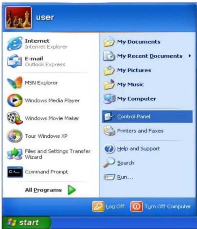
Go to desktop and click Start → Control Panel.

At control panel, double click Network Connections.
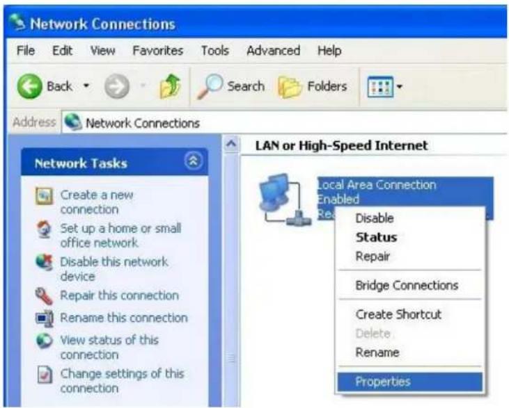
All your connections will be displayed on the window. Go to Local Area Connection and click mouse right button. A menu will appear, select Properties.
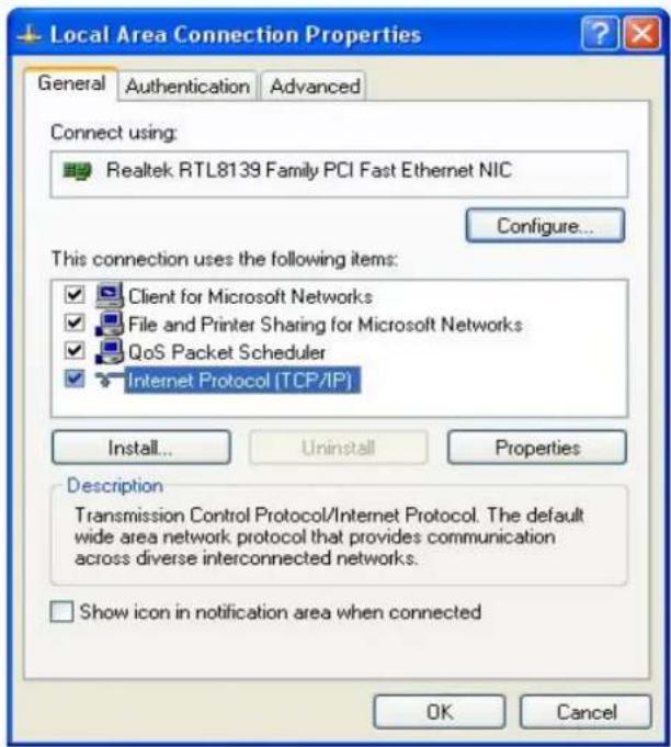
At Local Area Connection Properties window, select the General tab. Select Internet Protocol (TCP/IP) and then click Properties.
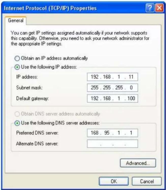
If you use DHCP to get IP automatically, select Obtain an IP address automatically and then click OK to finish the setting. The router supports DHCP, therefore any PC connected to LAN port of
the router can automatically get IP address.
If you get IP manually, select Use the following IP address. The factory default router LAN IP address is 192.168.1.100. Therefore, we use an IP address located in 192.168.1.x block to get connect to the router. Here we use 192.168.1.11 as an example. Click OK to finish the setting.
3.3 Access Router Home Page from Web Browser
This router can be configured through its web pages. Follow the steps below to access the router web pages.

Start your Internet browser, enter http://192.168.1.100 and press Enter.

A dialogue box will pop up to ask you for user name and password. The factory default User name is admin, password is admin. Enter the user name and password and then click OK to login.

If you login successfully, the router main web page will appear and you can start to configure the router from web pages.
3.4 Enable UPnP on Windows
The UPnP (Universal Plug and Play) enables communication between any two devices under the command of any control device on the local network.
PCs that have enabled UPnP function are informed when a device, this Router, for example, is connected to the local network.
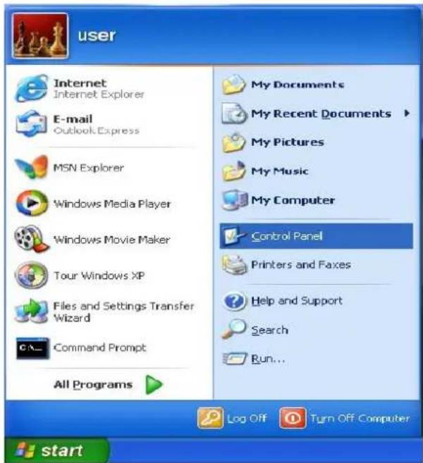
Go to desktop and click Start → Control Panel.
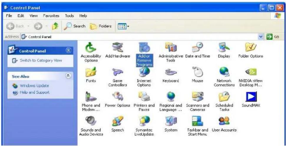
At Control Panel window, double click Add or Remove Programs.

Click Add/Remove Windows Components.
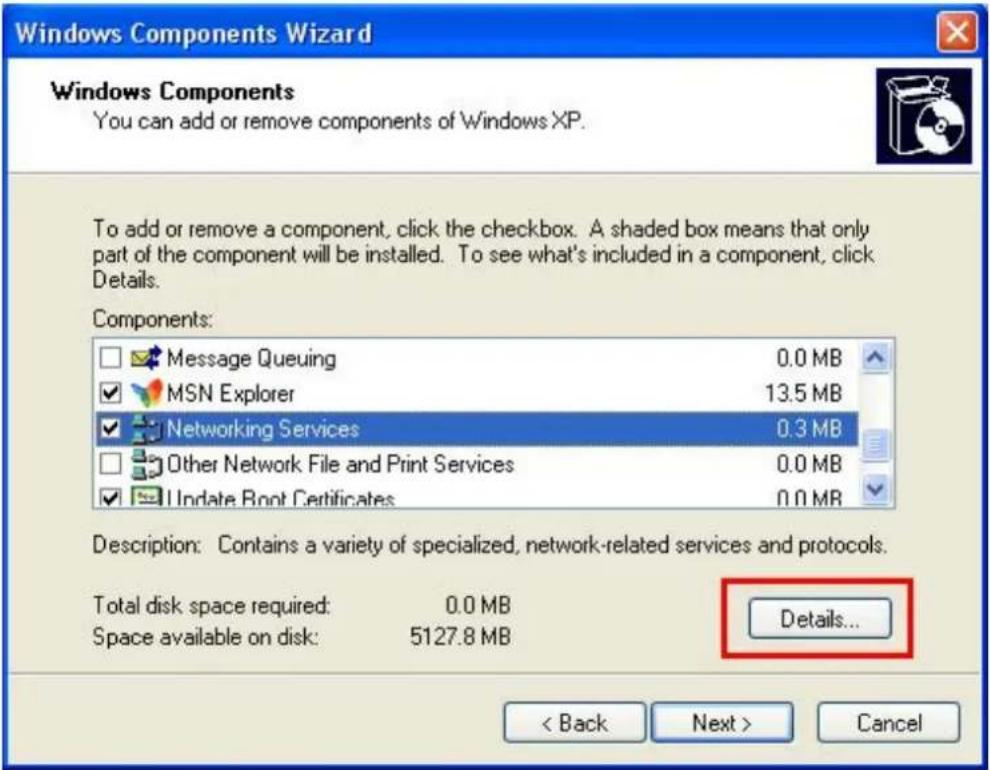
Select Network Services and then click Details.

Tick Universal Plug and Play and then click OK.
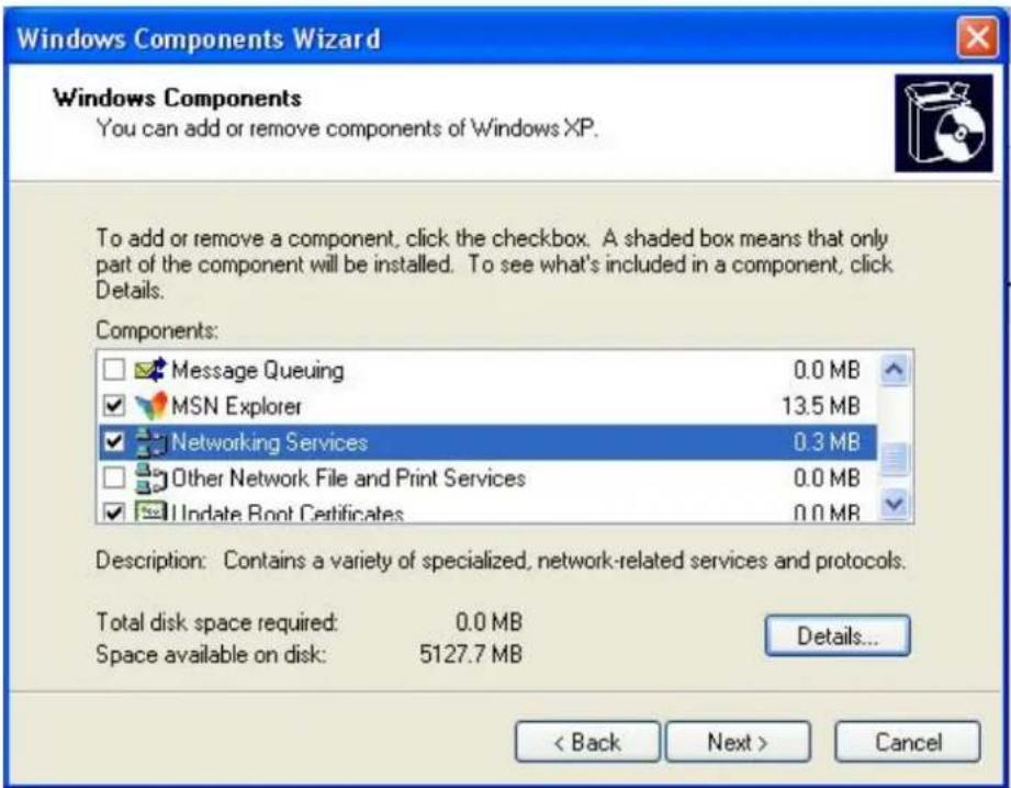
Back to this window, click Next. Windows will install the component automatically.
- Depends on the version of your OS, the original Windows CD might be required after this step. If so, please insert your original Windows CD.
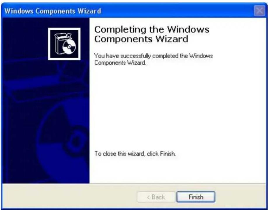
Click Finish.

Once the UPnP is enabled, the computer will be informed by this icon when a new device is connected to the local network. You can click this icon to get the UPnP-supported device list.
Chapter 4 Settings
4.1 Quick Setup
Quick Setup IP Configuration NAT Setup Firewall Setup USB Application System Setup Status & Log Logout
Quick Setup supports 4 WAN Connection Types - ADSL Dialup (PPPoE), ADSL Static IP, Automatic IP and Cable Modem (DHCP). If you do not know your WAN type, consult your ISP. Start quick setup by selecting your WAN Connection Type from the drop-down list.
4.1.1 ADSL Dialup (PPPoE)
If your ISP provides you the ADSL Dialup, please follow the following steps to setup your WAN connection.

[Page 1] Select ADSL Dialup from the drop-down list.

[Page 2] Input the User Name and Password provided by your ISP. Click Next.

[Page 3] Click the services that you want to block and input the time period that you want the selected services to be blocked. If you don't want to block any services, leave all options empty.
4.1.2 Static IP
If your ISP provides you the static IP, please follow the following steps to setup your WAN connection.

[Page 1] Select ADSL Static IP from the drop-down list.
| Quick Setup | ||
| WAN IP Setting | ||
| Your Internet connection type is ADSL static IP and you have been assigned a static IP from your Internet Service Provider (ISP). | ||
| IP Address: | ||
| Subnet Mask: | ||
| Default Gateway: | ||
| WAN DNS Setting | ||
| DNS Server1: | ||
| DNS Server2: | ||
| Previous | Next | |
[Page 2] Input the IP Address, Subnet Mask, Default Gateway, and DNS Server provided by your ISP.
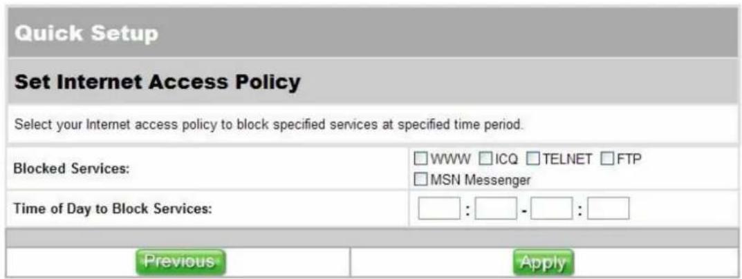
[Page 3] Click the services that you want to block and input the time period that you want the selected services to be blocked. If you don't want to block any services, leave all options empty.
4.1.3 Automatic IP
If your ISP provides you the automatic IP, please follow the following steps to setup your WAN connection.
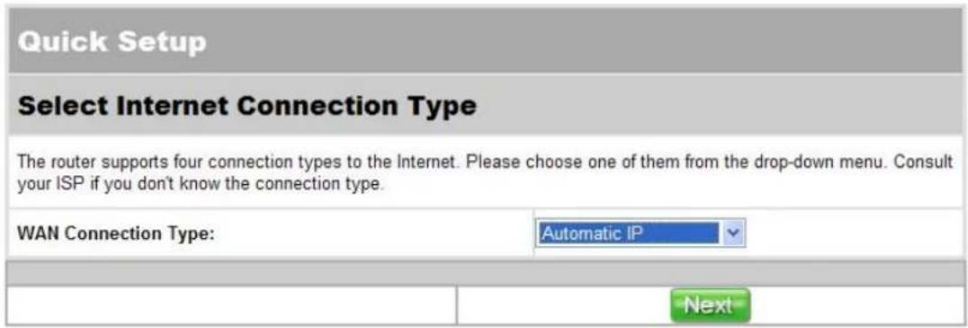
[Page 1] Select Automatic IP from the drop-down list.

[Page 2] Click the services that you want to block and input the time period that you want the selected services to be blocked. If you don't want to block any services, leave all options empty.
4.1.4 Cable Modem (DHCP)
If your ISP provides you the Cable Modem (DHCP), please follow the following steps to setup your WAN connection.
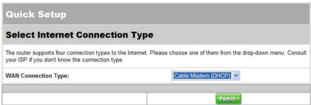
[Page 1] Select Cable Modem (DHCP) from the drop-down list.
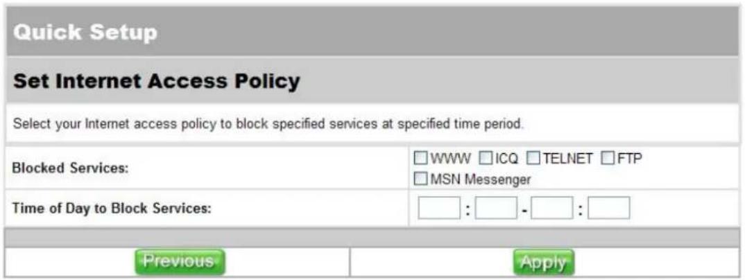
[Page 2] Click the services that you want to block and input the time period that you want the selected services to be blocked. If you don't want to block any services, leave all options empty.
4.2 IP Configuration
Quick Setup IP Configuration NAT Setup Firewall Setup USB Application System Setup Status & Log Logout
IP Configuration allows you to configure some basic functions including IP Setup, DHCP Server, Routing Table and Miscellaneous.
4.2.1 IP Setup
Quick Setup IP Configuration NAT Setup Firewall Setup USB Application System Setup Status & Log Logout
IP Configuration
IP Setup DHCP Server Routing Table Miscellaneous
You can use IP Setup section to configure your WAN connection and LAN IP. WAN connections are divided into four types, each type require different settings. Please check your WAN connection type and follow the corresponding instruction to complete the setting.
ADSL Dialup (PPPoE)

WAN Connection Type:
Select ADSL Dialup (PPPoE) from the drop-down list.
WAN DNS Setting:
Select Yes to get DNS Server automatically.
PPPoE Account:
Input the user name and password provided by your ISP.
The MTU value can be changed if required.
WAN MAC Address Setting:
This has a default value given by the manufacturer and you are recommended not to change this value.
LAN IP Setting:
There is a default LAN IP given by the manufacturer. You can change this as required. Please note that you should use the new IP address to login to this router.
Apply/Cancel:
Click Apply to save the settings or click Cancel to aboard.
ADSL Static IP

WAN Connection Type:
Select ADSL Dialup (PPPoE) from the drop-down list.
WAN IP Setting:
Input the IP Address, Subnet Mask and Default Gateway provided to you by your ISP.
WAN DNS Setting:
Select No to set the DNS manually and input the DNS Server IP. If you don't know, please check with your ISP.
The MTU value can be changed if required.
WAN MAC Address Setting:
This has a default value given by the manufacturer and you are recommended not to change this value.
LAN IP Setting:
There is a default LAN IP given by the manufacturer. You can change this as required. Please note that you should use the new IP address to login to this router.
Apply/Cancel:
Click Apply to save the settings or click Cancel to aboard.
Automatic IP
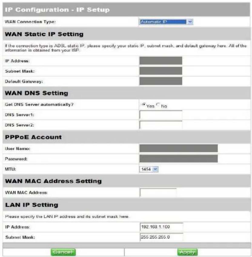
WAN Connection Type:
Select Automatic IP from the drop-down list.
WAN DNS Setting:
Select Yes to get DNS Server automatically.
WAN MAC Address Setting:
This has a default value given by the manufacturer and you are recommended not to change this value.
LAN IP Setting:
There is a default LAN IP given by the manufacturer. You can change this as required. Please note that you should use the new IP address to login to this router.
Apply/Cancel:
Click Apply to save the settings or click Cancel to aboard.
Cable Modem (DHCP)
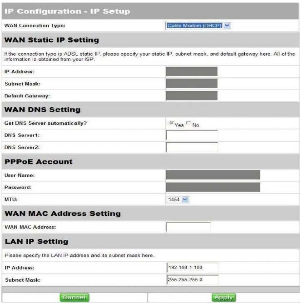
WAN Connection Type:
Select Automatic IP from the drop-down list.
WAN DNS Setting:
Select Yes to get DNS Server automatically.
WAN MAC Address Setting:
This has a default value given by the manufacturer and you are recommended not to change this value.
LAN IP Setting:
There is a default LAN IP given by the manufacturer. You can change this as required. Please note that you should use the new IP address to login to this router.
Apply/Cancel:
Click Apply to save the settings or click Cancel to aboard.
4.2.2 DHCP Server
IP Configuration
IP Setup
DHCP Server
Routing Table
Miscellaneous
DHCP Server supports up to 253 IP addresses for you local network. Follow the instructions to configure DHCP Server.
Enable DHCP Server:
Select Yes to enable or No to disable DHCP Server.
Domain Name:
Domain Name is the name which you had registered from NIC (Network Information Center). Ignore this part if managers don't apply for a domain name.
IP Pool Starting/Ending Address:
You can use this to set the IP range that the DHCP server can offer.
WINS (Windows Internet Naming Service) Server:
Input a WINS server IP if there is a WINS Server in the local network.
Apply/Cancel:
Click Apply to save the settings or click Cancel to aboard.
| IP Configuration - DHCP Server | |
| You can set up the router as a DHCP Server which automatically assigns IP addresses to DHCP clients in your local network. | |
| Enable DHCP Server? | Yes No |
| Domain Name: | |
| IP Pool Starting Address: | 192.168.0.1 |
| IP Pool Ending Address: | 192.168.0.254 |
| WINS Server Setting | |
| Primary WINS Server : | |
| Secondary WINS Server : | |
| Cancel | Apply |
4.2.3 Routing Table
Quick Setup IP Configuration NAT Setup Firewall Setup USB Application System Setup Status & Log Logout
IP Configuration
IP Setup DHCP Server Routing Table Miscellaneous
Routing Table page allows you to set routing rules to this router. This includes static routing and dynamic routing.

| Network / Host IP | Netmask | Gateway | |

Static Route:
Input the IP address of a destination network or a host of the routing rule. It could be a host address like 192.168.123.100 or a network address, such as 192.168.0.0. Click Add to add the rule to the routing table or select a rule from the table and then click Del to delete the rule.
Dynamic Route:
If you don't want to set any dynamic routing rule, select Disable. The default value is Rip2 and the router will build a routing table and get a path to the destination automatically.
4.2.4 Miscellaneous

Miscellaneous includes web server port setting, access control from WAN and DDNS setting. You can enable or disable some services when clients access from WAN.

Enable the DDNS Client:
Select Yes to enable or No to disable the DDNS client.
DDNS Server:
Select a DDNS server from the drop-down list or click Free Trial to link up a free trial address.
User Name or E-mail Address:
User name or e-mail address is used as an identity to login to some DDNS services.
Password or DDNS Key:
Password or DDNS key is used to login to some DDNS services.
Host Name:
Input the host name you have registered to Dynamic-DNS website.
Apply/Cancel:
Click Apply to save the settings or click Cancel to aboard.
4.3 NAT Setup
Quick Setup IP Configuration NAT Setup Firewall Setup USB Application System Setup Status & Log Logout
NAT Setup contains three functional items including Port Trigger, Virtual Server and Virtual DMZ.
4.3.1 Port Trigger

Application-triggered port forwarding opens a port only when a program needs to use it. You can set a trigger port to open an incoming port. When trigger ports are used, the system opens the specified incoming ports.
To setup port trigger, follow the instructions below.

Enable Port Trigger:
Select Yes to enable or No to disable port trigger.
Popular Applications:
The drop-down list has listed some popular applications, you can get the port number of an application by selecting from the drop-down list. Or you can also select User Defined from the list
and input the port number by yourself.
Trigger Ports:
Input the port number that will trigger the action. If this port was active by a program, the system will open the corresponding incoming port.
Incoming Ports:
Input the port number that will be open if the trigger port is active.
Protocol:
Select from the list whether this rule should be applied to TCP or UDP or both.
Description:
You can input some description of this rule.
Add/Del:
After fill up all your requirement of a rule, click Add to add the rule to the rule table. If you want to delete a rule from the table, select the rule and click Del. Then the high-lighted rule will be removed from the list.
Apply/Cancel:
Click Apply to save the settings or click Cancel to aboard.
4.3.2 Virtual Server

The hosts behind a firewall will be invisible from the outside. If you would like to setup a server such as web server or mail server behind the firewall, you will need to setup a virtual server. You can follow the instructions to setup a virtual server.

Enable Virtual Server:
Select Yes to enable or No to disable virtual server.
Well-Know Applications:
The drop-down list has listed some well-know applications, you can get the port number of an application by selecting from the drop-down list. Or you can also select User Defined from the list and input the local port number and server port number by yourself.
Local IP:
Input the local server IP. For example, the IP address of your web server on you network.
Local Port:
Input the port number. For example, port 80 for your web server.
Server Port:
Input the port number that WAN IP takes for this rule. It means all the connections from the Internet to your WAN IP on this port will be redirected to the local IP on the local port you have set.
Protocol:
Select from the list whether this rule should be applied to TCP or UDP or both.
Description:
You can input some description of this service.
Add/Del:
After fill up all your requirement of a rule, click Add to add the rule to
the rule table. If you want to delete a rule from the table, select the rule and click Del. Then the high-lighted rule will be removed from the list.
Apply/Cancel:
Click Apply to save the settings or click Cancel to aboard.
4.3.3 Virtual DMZ

You can redirect every connection from the Internet to a computer on your network by setting up a virtual DMZ. Every connection your WAN IP form the Internet will be redirected to the specified IP address on your network. However, this could also increase the security risk of your network. Follow the instructions to setup a virtual DMZ.

IP Address of the DMZ host:
Input the host IP address where you want all the connections to your WAN IP to be redirected to.
Apply/Cancel:
Click Apply to save the settings or click Cancel to aboard.
4.4 Firewall Setup
Quick Setup IP Configuration NAT Setup Firewall Setup USB Application System Setup Status & Log Logout
There are three ways to block connections. Connections can be blocked by their IP address, MAC address or URL.
4.4.1 IP Filter
Quick Setup IP Configuration NAT Setup Firewall Setup USB Application System Setup Status & Log Logout
Firewall Setup
IP Filter
MAC Filter
URL Filter
IP Filter blocks connections according to their IP addresses and ports. You can also set start time and end time if you only want to apply the filter rules during a specific period in a day.
| Firewall Setup - IP Filter | |||
| Properly configure the firewall will help you to block the access from the local network to Internet or from Internet to the local network. | |||
| Enable Firewall? | Yes No | ||
| Enable Firewall Log? | Yes No | ||
| IP Filter Setup | |||
| Filter Table | Add | Del | Help |
| Priority | Higher | Lower | |
| Well-Known Applications: | User Defined | ||||||
| Source IP | Port Range | Destination IP | Port Range | Protocol | Start Time | End Time | Type |
| BOTH | ACCEPT | ||||||
Cancel
Apply
Enable Firewall:
Select Yes to enable or No to disable firewall.
Enable Firewall Log:
Select Yes to enable or No to disable firewall log.
Source IP and Port Range:
Input the source IP address and port range for the filtering rule.
Destination IP and Port Range:
Input the destination IP address and port range for the filtering rule.
Protocol:
Select from the drop-down list whether certain filter rule should
apply to TCP or UDP or both.
Start Time/End Time:
Set a period of time to drop or accept the connection.
Type:
Select from the drop-down list for dropping or accepting the connection.
Add/Del:
After fill up all your requirement of a rule, click Add to add the rule to the rule table. If you want to delete a rule from the table, select the rule and click Del. Then the high-lighted rule will be removed from the list.
Priority:
A connection is to be accepted or to be dropped is according to the first matching rule from the top of the rule table. You can change the priority of a rule by select the rule and click Higher or Lower.
Apply/Cancel:
Click Apply to save the settings or click Cancel to aboard.
4.4.2 MAC Filter

MAC filter drops or accepts a connection according to its MAC address.
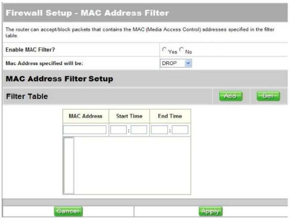
Enable MAC Filter:
Select Yes to enable or No to disable MAC filter.
MAC Address specified will be:
Select DROP or ACCEPT from the list to mean all the connections to the MAC addresses on the list should be dropped or accepted.
MAC Address:
Input the MAC address that you want to apply to this rule.
Start Time/End Time:
Set a period of time to drop or accept the connection.
Add/Del:
After fill up all your requirement of a rule, click Add to add the rule to the rule table. If you want to delete a rule from the table, select the rule and click Del. Then the high-lighted rule will be removed from the list.
Apply/Cancel:
Click Apply to save the settings or click Cancel to aboard.
4.4.3 URL Filter

URL filter blocks a connection according to its URL.
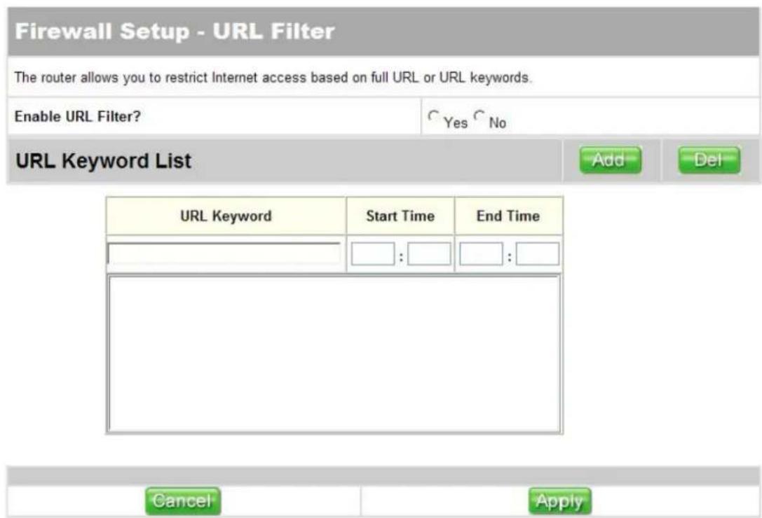
Enable URL Filter:
Select Yes to enable or No to disable URL filter.
URL Keyword:
Input a full URL or a keyword of an URL. For example, input "www.abc.com.tw" will only block the URL perfectly matches this URL while input "abc" will block all the connections that contain "abc" in its URL.
Start Time/End Time:
Set a period of time to drop or accept the connection.
Add/Del:
After fill up all your requirement of a rule, click Add to add the rule to the rule table. If you want to delete a rule from the table, select the rule and click Del. Then the high-lighted rule will be removed from the list.
Apply/Cancel:
Click Apply to save the settings or click Cancel to aboard.
4.5 USB Application

This router provides three USB applications, FTP server, Web camera and printer server.
4.5.1 FTP Server
Quick Setup IP Configuration NAT Setup Firewall Setup USB Application System Setup Status & Log Logout
USB Application
FTP Server
Web Camera
Printer Server
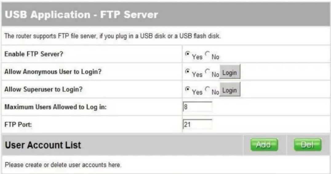
The FTP server function allows you to share files on the network. This product supports a file format of FAT12/16/32.
Please follow the steps below to configure FTP server.
| User Name | Password | Max. Login | Rights |
| Read/Write/Erase | |||
| Tom | 12345 | 5 | Read/Write/Erase |
| Boss | abcd | 8 | Super User |
| Cancel | Apply |
Enable FTP Server:
Select Yes to enable or No to disable FTP Server.
Allow Anonymous User to Login:
Select Yes to allow users use anonymous to login or select No to forbid users use anonymous to login.
Allow Super User to Login:
Select Yes to enable or No to disable user log in to FTP as super user.
Maximum Users Allowed to Login:
Input the maximum amount that the system can allow users to login at the same time.
FTP Port:
The default FTP Port is 21, you can change it if necessary.
Add/Del:
To add a user account, input user name, password, max login and file access right of the new user and then click Add. To delete a user account, select the user from the account list and then click Del.
Apply/Cancel:
Click Apply to save the settings or click Cancel to aboard.
How to operate on Windows:
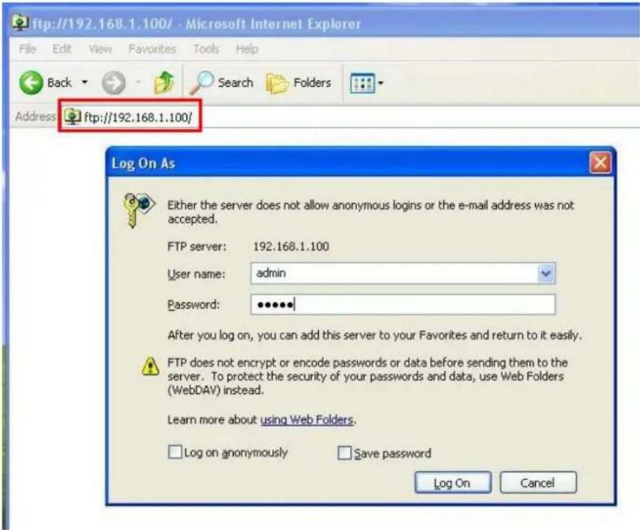
Open Internet browser and input the address of the router. For example, we use ftp://192.168.1.100 because the LAN IP address of our router is 192.168.1.100.
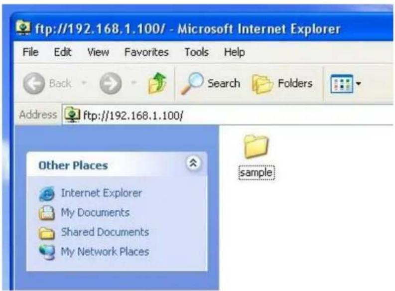
If the Allow Anonymous User to Login item is set to No, then a dialog will appear to ask you for user name and password. Enter the user name and password then click Log On. If the user name and password is valid, you can see the data as follows.
4.5.2 Print Server

The Print server function allows you to share printers on the network. Digitus DN-11009 support LPR printing protocol. Please follow the steps below to configure print server.
| USB Application - Print Server | |
| You can set the router as a USB print server. | |
| Enable Printer Server? | Yes No |
| USB Printer1 | |
| USB Printer1 Name: | |
| USB Printer1 Model: | |
| USB Printer2 | |
| USB Printer2 Name: | |
| USB Printer2 Model: | |
| Cancel | Apply |
Enable Print Server:
Select Yes to enable or No to disable print Server.
Printer1 Name:
This is the printer name of the first printer. There will be a default printer name. You can change it if you want. Remember this name will be the one you should use when adding printer on Windows.
Printer1 Model:
The model of the first printer.
Printer2 Name:
This is the printer name of the second printer. There will be a default printer name. You can change it if you want. Remember this name will be the one you should use when adding printer on Windows.
Printer2 Model:
The model of the second printer.
Apply/Cancel:
Click Apply to save the settings or click Cancel to aboard.
Add a printer on Windows:
Please follow the steps listed below to add a printer on Windows.

Go to "Start" select Printers and Faxes.

Click Add a printer.

Click Next.
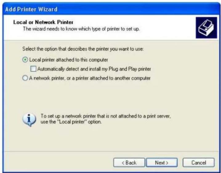
Select Local printer attached to this computer then click next.
![Add Printer Wizard Select a Printer Port Computers communicate with printers through ports. Select the port you want your printer to use. If the port is not listed, you can create a new port. Use the following port: LPT1: [Recommended Printer Port] Note: Most computers use the LPT1: port to communic…](/content/2026/05/1021314/images/701e52cfc6e391e7f19ed1d5d0175c81fb43db7f01dc08d7083662ba2e7825bc.jpg)
Select Create a new port and set type of port to Standard TCP/IP Port. Click next.

A wizard of adding a new standard TCP/IP port will appear. Click Next.

Give a name to this new port. Then click Next.

Select device type to Custom. Then click Settings.
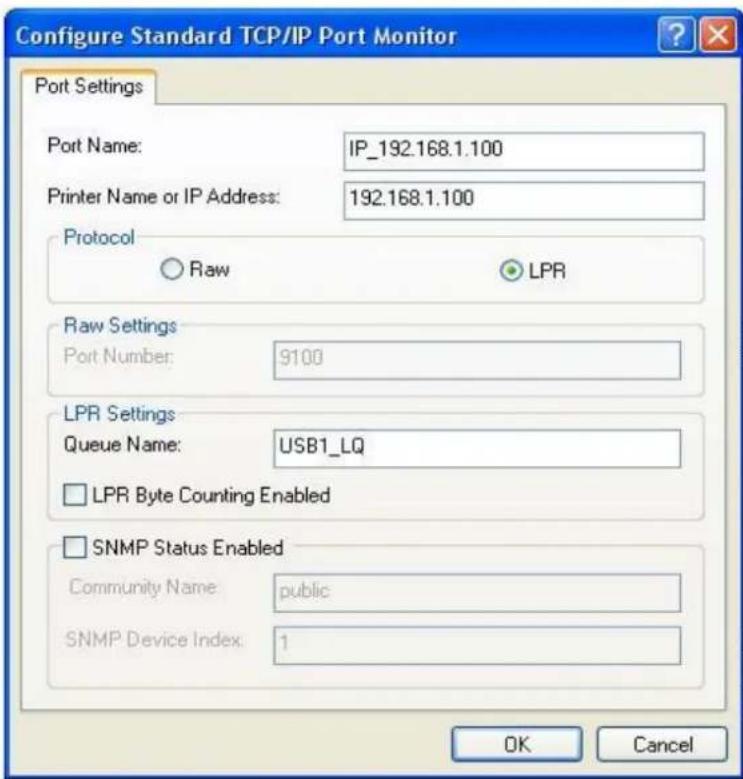
Set protocol to LPR and set queue name as the printer name you set on router web site. Here we use USSB1_LQ for example. Click OK.
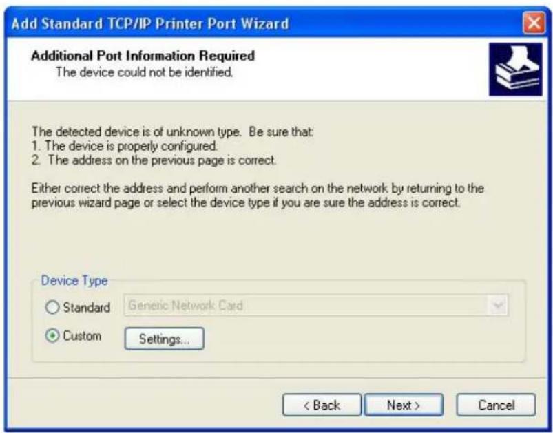
Once the device type is configures, the wizard will back to this page. Click Next.
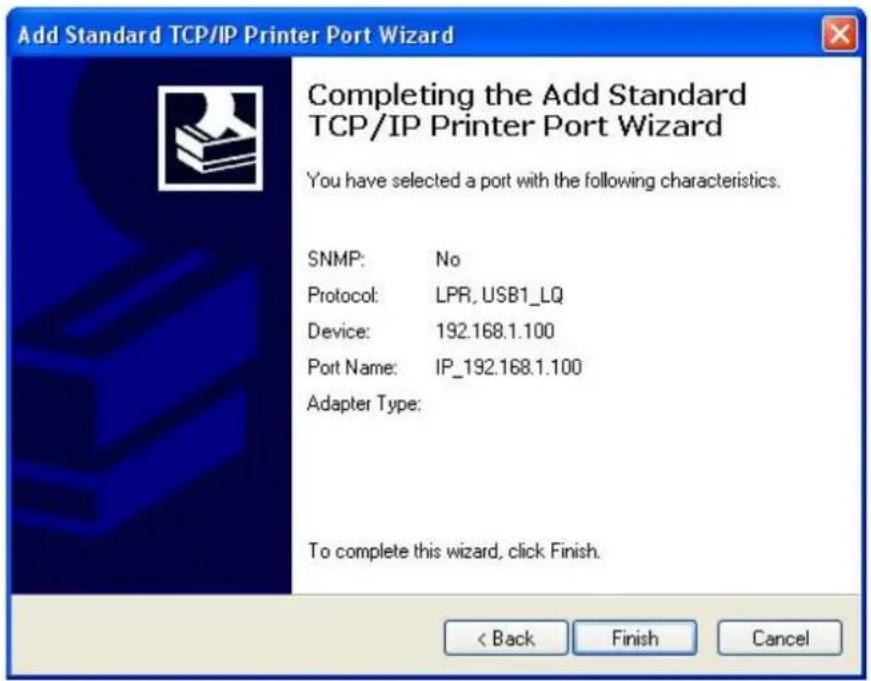
Click finish to complete the add printer port wizard.

Select printer driver. Here we use HP LaserJet 1200 Series PCL for example. Click Next.
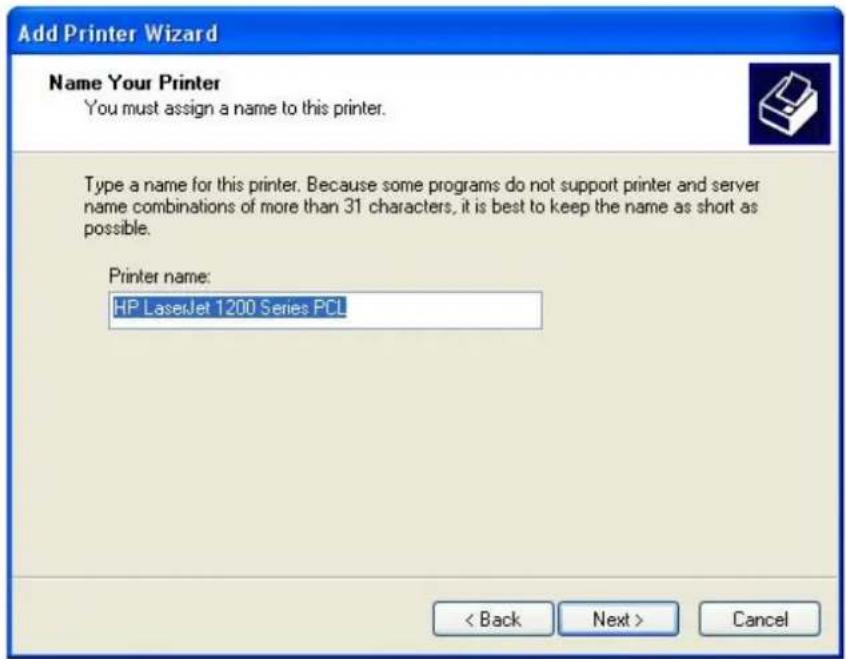
Give this printer a name. This name is used for Windows display. There will be a default printer name, you can change if necessary.
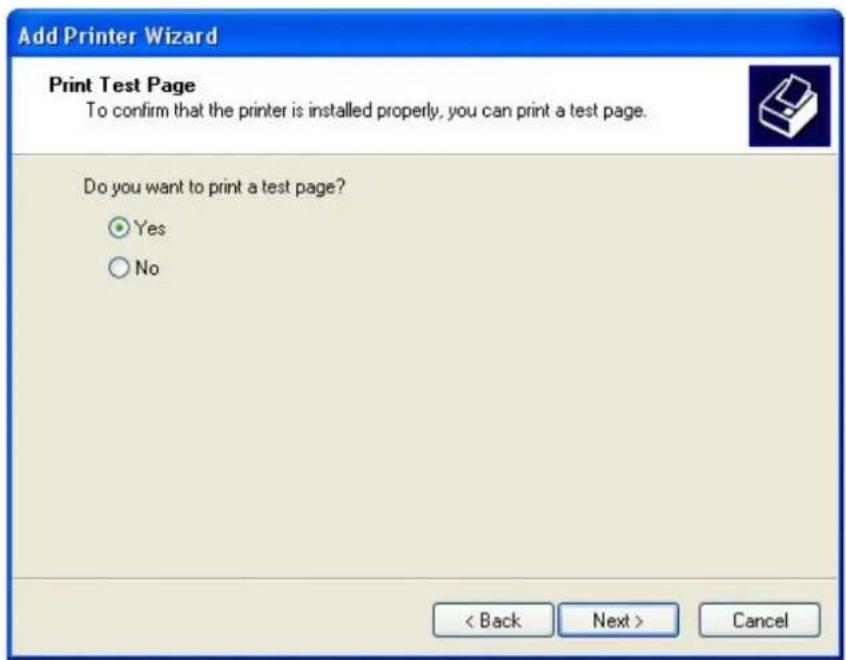
Select whether you want to print a test page or not. Here we select Yes as an example.

Click finish to complete the add printer wizard.

If the test page is printed, click Ok. Otherwise, click Troubleshoot.
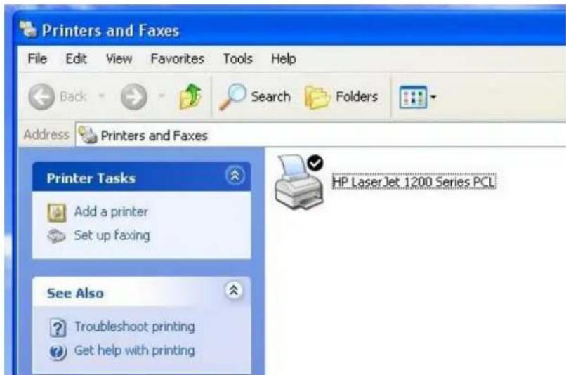
There will be a new printer added to your printer list.
4.6 System Setup

4.6.1 User Setting

System Setup
| User Setting | Time Setup | Firmware Upgrade | Setting Backup | Restore Default | Wake On LAN |
You can set the name and password for the administrator of the
router.

Input the new user name and password that is to be used as the administrator of the router. Retype the password and click Apply to save the settings or Cancel to aboard.
*Note that you should use the new user name and password to login to the router web site once applied.
4.6.2 Time Setup

You can set the router clock to your local time and daylight saving time. You can get current time from NTP (Network Time Protocol) server or from your local computer. Please follow the steps below to set your router time.
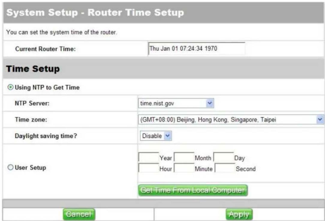
Current Router Time:
This field displays your current router time.
Using NTP to Get Time:
Select this if you want to get time from NTP server.
NTP Server:
Select a NTP server from the drop-down list.
Time Zone:
Choose your local time zone from the drop-down list.
Daylight Saving Time:
Select an option to enable or disable daylight saving time.
User Setup:
Select this if you prefer setup time manually. Input the time for each field or you can also get time from your local computer.
Get Time From Local Computer:
Click to get time from your local computer. The time get from your computer will be displayed at the user setup field.
Apply/Cancel:
Click Apply to save the settings or click Cancel to aboard. Once applied, the current router time field will display your new router time.
4.6.3 Firmware Upgrade

This page displays the current firmware information of your router. You can always keep your router updated to the latest version from this page as well. Please follow the steps below to upgrade router firmware.

Product ID:
This field displays product ID of your router.
Firmware Version:
This field displays the firmware version that your router is using currently.
New Firmware File:
Click Browse to get the new firmware that you would like to upload.
Upload:
Click Upload to upgrade the firmware.
4.6.4 Setting Backup

You can save your current configuration to a file, and you can also load your settings from a file that you have saved. Please follow the steps below to save or load your settings.
System Setup - Setting Management
You can save current settings of this router to a file, or load settings from a file.
Save Settings As a File
Please click HERE to save current settings of this router into a file.
Load Settings From a File
Please specify the path and the name of the downloaded file in the "New Setting File" as below. Then click the "Upload" button to restore settings into the router. It will take a while and then the router will reboot.
New Setting File:

Upload
Click Here to save your current settings into a file for backing up. If you want to get your original settings back, click Browse to get your saved settings and click Upload to apply. The system will reboot automatically, all the settings will be restored to the original value after reboot.
You may restore the router to factory default settings from this page. To restore default settings, simply click the Restore button. The system will reboot automatically. Settings will be reset to factory default values after reboot.
System Setup - Restore Default Settings
Click the Restore button to restore the factory default settings. Then, wait for the router to reboot.
Restore
4.6.6 Wake on LAN

For computers connected on this router's LAN port, the Wake on LAN function allows you to turn on a computer through its MAC address. The computer must support Wake on LAN. Please check the BIOS setup in your computer.

To wake up a computer, please enter the MAC address of the computer, and then click Wake Up to turn on the computer or click Cancel to aboard and clear the setting.
4.7 Status & Log
Quick Setup IP Configuration NAT Setup Firewall Setup USB Application System Setup Status & Log Logout
Status & Log provides many useful information of the system. Including the current WAN and LAN status of the system, the DHCP offered by this DHCP server and the login record of the system.
4.7.1 Status

Status page shows some important information and status of the interfaces of this router.
Status & Log - Status
This page shows some important information and status about the router. To update the display, click Refresh button.
| System Up Time: | 001 days 01:57:52 |
WAN Interface
| Connection Type: | ADSL Static IP |
| IP Address: | 61.218.78.46 |
| Subnet Mask: | 255.255.255.0 |
| Default Gateway: | 61.218.78.33 |
| DNS Servers: | 168.95.1.1 |
| MAC Address: | 00:11:E5:5A:29:31 |
| Connection Status: | Connected. |
LAN Interface
| IP Address: | 192.168.1.100 |
| Subnet Mask: | 255.255.255.0 |
| MAC Address: | 00:11:E5:5A:29:30 |
USB Printer
| Printer1 Name: | |
| Printer1 Model: | |
| Printer1 Status: | Printer Off-line |
| Printer2 Name: | |
| Printer2 Model: | |
| Printer2 Status: | Printer Off-line |
Refresh
System Up Time:
This field shows the lasting time from the last time this system up to current.
WAN Interface
Connection Type:
This field shows the WAN connection type this system is using.
IP Address:
This field shows the IP address of the system WAN port.
Subnet Mask:
This field shows the subnet mask of the system WAN port.
Default Gateway:
This field shows the gateway of the system WAN port.
DNS Servers:
This field shows the DNS server IP address of the system WAN port.
MAC Address:
This field shows the MAC address of the system WAN port.
Connection Status:
This field shows the current WAN connection status. The value would be Connected or Not connected.
LAN Interface
IP Address:
This field shows the IP address of the system LAN port.
Subnet Mask:
This field shows the subnet mask of the system LAN port.
MAC Address:
This field shows the MAC address of the system LAN port.
USB Printer
Printer Name:
This field shows the printer name of the printer connected to system USB port.
Printer Model:
This field shows the printer name of the printer connected to system USB port.
Printer Status:
This field shows the printer status of the printer connected to system USB port.
Refresh:
Click Refresh to get the latest information of the system.
4.7.2 DHCP Leases
Quick Setup IP Configuration NAT Setup Firewall Setup USB Application System Setup Status & Log Logout
Status & Log

When the system DHCP server function is on, this system will offer
IP addresses to other network devices. This page shows the IP address offered and to which MAC address does this IP address offered.

Refresh:
Click Refresh to get the latest information of the DHCP leases
4.7.3 System Log

The system records some of its activities automatically. An alerting email could be send to inform users when the system log is full. The logged information can be saved to computer manually.
Status & Log - System Log
You can view the log of router activities. To update the display of the log, click Refresh button.
| Time | Type of Services | Description |
| 03/27 17:35:43 | WEB | 192.168.0.115 User login to web! |
| 03/27 17:18:55 | WEB | 192.168.0.115 User login to web! |
| 03/27 16:29:07 | FireWall | Packet rejected by MAC rule, MAC addr is ff:FF:4D:FF:09:FF |
| 03/27 11:36:05 | FireWall | Packet rejected by MAC rule, MAC addr is ff:FF:4D:FF:09:FF |
| 03/27 10:44:18 | WEB | 192.168.0.110 User login to web! |
| 03/27 07:11:05 | FireWall | Packet rejected by MAC rule, MAC addr is ff:FF:4D:FF:09:FF |
| 03/27 04:24:06 | FireWall | Packet rejected by MAC rule, MAC addr is ff:FF:4D:FF:09:FF |
| 03/27 03:56:36 | FireWall | Packet rejected by MAC rule, MAC addr is ff:FF:4D:FF:09:FF |
| 03/27 03:50:36 | FireWall | Packet rejected by MAC rule, MAC addr is ff:FF:4D:FF:09:FF |
| 03/27 01:54:33 | FireWall | Packet rejected by MAC rule, MAC addr is ff:FF:4D:FF:09:FF |
| 03/26 23:25:05 | FireWall | Packet rejected by MAC rule, MAC addr is ff:FF:4D:FF:09:FF |
| 01/01 12:12:41 | FireWall | Packet rejected by MAC rule, MAC addr is ff:FF:4D:FF:09:FF |
EMail Alert
| Send an alert when logs are full: | Disable | ||
| Email Address: | |||
| Outgoing Mail Server: | |||
| Outgoing Mail Server (SMTP server) requires authentication: | YesNo | ||
| User name: | |||
| Password: | |||
| Save | Mail Now | Refresh | |
System Log:
The log records the time, type of services and description of router activities.
Send an alert when logs are full:
Select an option to enable or disable alerting email. If enabled, the system will send an email to the designated email address when logs are full.
Email Address:
Input the email address that you want the alerting email to be sent to.
Outgoing Mail Server:
Input the outgoing mail server address.
Outgoing Mail Server (SMTP server) requires authentication:
Select whether your outgoing mail server requires authentication or not.
User Name:
Input the user name of your mail server authentication.
Password:
Input the password of your mail server authentication.
Save:
Click Save to save the logs to your computer.
Mail Now:
Click Mail Now to send an alerting email immediately.
Refresh:
Click Refresh to get the latest log status.
4.8 Logout
Quick Setup IP Configuration NAT Setup Firewall Setup USB Application System Setup Status & Log Logout
To logout from router web page, click Logout at the very right of the main menu.
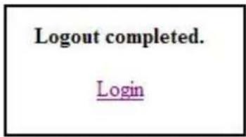
A page will inform you that your logout has completed. If you want to login again, click Login.
Appendix Factory Default Values
IP Configuration
WAN Connect Type: Automatic IP
WAN DNS: Automatic
PPPoE's MTU: 1492
LAN IP: 192.168.1.100
LAN Subnet Mask: 255.255.255.0
DHCP Server: Enabled
DHCP Server Starting IP Address: 192.168.1.1
DHCP Server Ending IP Address: 192.168.1.254
R I P : D i s a b l e d
Web Server Port: 80
Ping from WAN: Enabled
Web Access from WAN: Disabled
Print Server Access from WAN: Disabled
FTP Access from WAN: Disabled
Webcam Access from WAN: Disabled
D D N S : D i s a b l e
NAT
Port Trigger: Disabled
Virtual Server: Disabled
Virtual DMZ: Disabled
Firewall
IP Filter: Disabled
MAC Filter: Disabled
URL Filter: Disbaled
USB Application
FTP Server: Disabled
Allow FTP Anonymous Login: No
Allow FTP Superuser Login: No
Max. Concurrent FTP Users: 8
FTP Port: 21
Printer Server: Disabled
System
Administrator ID: admin
Administrator Password: admin
Time Setup: Use NTP to get time
NTP Server: time.nist.gov
Time Zone :
G M



- CHAPTER 1 INTRODUCTION....3
- CHAPTER 2 PRODUCT OVERVIEW....4
- CHAPTER 3 INSTALLATION....6
- CHAPTER 4 SETTINGS....15
- APPENDIX FACTORY DEFAULT VALUES....57
- CHAPTER 1 INTRODUCTION
- 1.1 HARDWARE SPECIFICATION
- 1.2 FEATURES
- CHAPTER 2 PRODUCT OVERVIEW
- 2.1 PACKAGE CONTENTS
- 2.2 HARDWARE DESCRIPTION
- 2.2.1 REAR PANEL
- 2.2.2 FRONT PANEL
- 2.2.3 LED INDICATORS
- 2.3 TYPICAL USAGE
- CHAPTER 3 INSTALLATION
- 3.1 HARDWARE CONNECTIONS
- 3.2 IP SETTING ON WINDOWS
- 3.3 ACCESS ROUTER HOME PAGE FROM WEB BROWSER
- 3.4 ENABLE UPNP ON WINDOWS
- CHAPTER 4 SETTINGS
- 4.1 QUICK SETUP
- 4.1.1 ADSL DIALUP (PPPOE)
- 4.1.2 STATIC IP
- 4.1.3 AUTOMATIC IP
- 4.1.4 CABLE MODEM (DHCP)
- 4.2 IP CONFIGURATION
- 4.2.1 IP SETUP
- IP CONFIGURATION
- ADSL DIALUP (PPPOE)
- WAN CONNECTION TYPE
- WAN DNS SETTING
- PPPOE ACCOUNT
- WAN MAC ADDRESS SETTING
- LAN IP SETTING
- APPLY/CANCEL
- ADSL STATIC IP
- WAN IP SETTING
- AUTOMATIC IP
- CABLE MODEM (DHCP)
- 4.2.2 DHCP SERVER
- ENABLE DHCP SERVER
- DOMAIN NAME
- IP POOL STARTING/ENDING ADDRESS
- WINS (WINDOWS INTERNET NAMING SERVICE) SERVER
- 4.2.3 ROUTING TABLE
- STATIC ROUTE
- DYNAMIC ROUTE
- 4.2.4 MISCELLANEOUS
- ENABLE THE DDNS CLIENT
- DDNS SERVER
- USER NAME OR E-MAIL ADDRESS
- PASSWORD OR DDNS KEY
- HOST NAME
- 4.3 NAT SETUP
- 4.3.1 PORT TRIGGER
- ENABLE PORT TRIGGER
- POPULAR APPLICATIONS
- TRIGGER PORTS
- INCOMING PORTS
- PROTOCOL
- DESCRIPTION
- ADD/DEL
- 4.3.2 VIRTUAL SERVER
- ENABLE VIRTUAL SERVER
- WELL-KNOW APPLICATIONS
- LOCAL IP
- LOCAL PORT
- SERVER PORT
- 4.3.3 VIRTUAL DMZ
- IP ADDRESS OF THE DMZ HOST
- 4.4 FIREWALL SETUP
- 4.4.1 IP FILTER
- FIREWALL SETUP
- ENABLE FIREWALL
- ENABLE FIREWALL LOG
- SOURCE IP AND PORT RANGE
- DESTINATION IP AND PORT RANGE
- START TIME/END TIME
- TYPE
- PRIORITY
- 4.4.2 MAC FILTER
- ENABLE MAC FILTER
- MAC ADDRESS SPECIFIED WILL BE
- MAC ADDRESS
- 4.4.3 URL FILTER
- ENABLE URL FILTER
- URL KEYWORD
- 4.5 USB APPLICATION
- 4.5.1 FTP SERVER
- USB APPLICATION
- ENABLE FTP SERVER
- ALLOW ANONYMOUS USER TO LOGIN
- ALLOW SUPER USER TO LOGIN
- MAXIMUM USERS ALLOWED TO LOGIN
- FTP PORT
- HOW TO OPERATE ON WINDOWS
- 4.5.2 PRINT SERVER
- ENABLE PRINT SERVER
- PRINTER1 NAME
- PRINTER1 MODEL
- PRINTER2 NAME
- PRINTER2 MODEL
- ADD A PRINTER ON WINDOWS
- 4.6 SYSTEM SETUP
- 4.6.1 USER SETTING
- SYSTEM SETUP
- 4.6.2 TIME SETUP
- CURRENT ROUTER TIME
- USING NTP TO GET TIME
- NTP SERVER
- TIME ZONE
- DAYLIGHT SAVING TIME
- USER SETUP
- GET TIME FROM LOCAL COMPUTER
- 4.6.3 FIRMWARE UPGRADE
- PRODUCT ID
- FIRMWARE VERSION
- NEW FIRMWARE FILE
- UPLOAD
- 4.6.4 SETTING BACKUP
- SYSTEM SETUP - SETTING MANAGEMENT
- SAVE SETTINGS AS A FILE
- LOAD SETTINGS FROM A FILE
- SYSTEM SETUP - RESTORE DEFAULT SETTINGS
- 4.6.6 WAKE ON LAN
- 4.7 STATUS & LOG
- 4.7.1 STATUS
- SYSTEM UP TIME
- WAN INTERFACE
- CONNECTION TYPE
- IP ADDRESS
- SUBNET MASK
- DEFAULT GATEWAY
- DNS SERVERS
- CONNECTION STATUS
- LAN INTERFACE
- USB PRINTER
- PRINTER NAME
- PRINTER MODEL
- PRINTER STATUS
- REFRESH
- 4.7.2 DHCP LEASES
- STATUS & LOG
- 4.7.3 SYSTEM LOG
- STATUS & LOG - SYSTEM LOG
- EMAIL ALERT
- SYSTEM LOG
- SEND AN ALERT WHEN LOGS ARE FULL
- EMAIL ADDRESS
- OUTGOING MAIL SERVER
- OUTGOING MAIL SERVER (SMTP SERVER) REQUIRES AUTHENTICATION
- USER NAME
- PASSWORD
- SAVE
- MAIL NOW
- 4.8 LOGOUT
- APPENDIX FACTORY DEFAULT VALUES
- NAT
- FIREWALL
- SYSTEM
Brand : Digitus
Model : DN-11009
Category : Router