
P93DE - Printer MITSUBISHI - Free user manual and instructions
Find the device manual for free P93DE MITSUBISHI in PDF.


| Type | Digital Monochrome Printer |
| Model | P93DW / P93DE |
| Dimensions (W x H x D) | 6.1 x 3.5 x 10.1 in (154 x 89.5 x 256 mm) |
| Weight | 6.2 lb (2.8 kg) |
| Power Supply | 100-240 V AC, 50/60 Hz, 1.5-0.8 A |
| Power Consumption | 1.5-0.8 A (varies by voltage) |
| Connection | USB 2.0 Hi-Speed (Series B receptacle) |
| Resolution | 1280 x 1280 pixels (standard), up to 1280 x 5760 pixels |
| Gradation | 256 shades of gray |
| Print Speed | 5.0 seconds per print (standard) |
| Print Size | 4 x 4 in (100 x 100 mm) standard; max 4 x 17.7 in (100 x 450 mm) |
| Thermal Paper Types | KP65HM-CE, KP65H-CE, KP61S-CE, KP61B-CE, KP91HG-CE (Mitsubishi brand recommended) |
| Operating Temperature | 41-104 °F (5-40 °C) |
| Operating Humidity | 20-80% RH (non-condensing) |
| Safety Classification | Class I (must be earthed); UL2601-1, CAN/CSA C22.2 No. 601.1, EN60601-1 |
| Front Panel Controls | Power switch, BRT/CONT button, UP/DOWN buttons, LOCK button, FEED button, COPY button, print exit/cutter |
| Brightness/Contrast Adjustment | Range -19 to +19; adjustable via BRT/CONT and UP/DOWN buttons |
| Copy Printing | 1 to 200 copies; press COPY button to set number |
| Button Lock | Press LOCK button for 1 second to lock/unlock UP/DOWN buttons; DIP switch No. 1 also locks all buttons |
| Error Indicators | Overheat (blinking), No paper (EP), Door open (Eo), Gear lock (EL), Button input error (Eb) |
| Maintenance | Clean thermal head with supplied cleaning paper after 10 paper rolls; clean rubber roller with ethyl alcohol |
| Spare Parts / Repairability | Thermal head replaceable by qualified service personnel; no user-serviceable parts inside |
| Standard Accessories | AC power cord, thermal paper KP65HM-CE (1 roll), cleaning paper (1 sheet), printer driver CD-ROM |
| Compliance | FCC Class A, ICES-003 Class A, CE (EC Directives 89/336/EEC, 73/23/EEC, 93/42/EEC, 93/68/EEC) |
Frequently Asked Questions - P93DE MITSUBISHI
User questions about P93DE MITSUBISHI
0 question about this device. Answer the ones you know or ask your own.
Ask a new question about this device
Download the instructions for your Printer in PDF format for free! Find your manual P93DE - MITSUBISHI and take your electronic device back in hand. On this page are published all the documents necessary for the use of your device. P93DE by MITSUBISHI.
USER MANUAL P93DE MITSUBISHI
DIGITAL MONOCHROME PRINTER
MODEL
P93DW
P93DE
OPERATION MANUAL
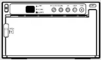
THIS OPERATION MANUAL IS IMPORTANT TO YOU.
PLEASE READ IT BEFORE USING YOUR DIGITAL MONOCHROME PRINTER.

DIGITAL MONOCHROME
PRINTER

This digital monochrome printer complies with the requirements of the EC Directive 89/336/EEC, 73/23/EEC, 93/42/EEC and 93/68/EEC.
The electro-magnetic susceptibility has been chosen at a level that gains proper operation in residential areas, on business and light industrial premises and on small-scale enterprises, inside as well as outside of the buildings. All places of operation are characterised by their connection to the public low voltage power supply system.
WARNING:
In the USA or Canada, use the AC power cord according to the recommendations as below, in order to comply with UL2601-1 and CAN/CSA C22.2 No. 601.1.
Case 1. Connect to the 120V receptacle of the room or the host equipment.
The AC power cord should be UL or CSA approved and consist of type SJT, size 16 or 18AWG, length 2.5m or shorter cord with IEC320/C13 type, 125V 10A or higher rating connector and NEMA 5-15 type, 125V 10A or higher rating, Hospital Grade plug.
Case 2. Connect to the 230V receptacle of the room or the host equipment.
The AC power cord should be UL or CSA approved and consist of type SJT, size 16 or 18AWG, length 2.5m or shorter cord with IEC320/C13 type, 250V 10A or higher rating connector and NEMA 6-15 type, 250V 10A or higher rating, Hospital Grade plug.
Case 3. Connect to the 120V receptacle of the host equipment.
The AC power cord should be UL or CSA approved and consist of type SJT, size 16 or 18AWG, length 2.5m or shorter cord with IEC320/C13 type, 125V 10A or higher rating connector and IEC320-2.2/E type, 125V 10A or higher rating plug.
Case 4. Connect to the 230V receptacle of the host equipment.
The AC power cord should be UL or CSA approved and consist of type SJT, size 16 or 18AWG, length 2.5m or shorter cord with IEC320/C13 type, 250V 10A or higher rating connector and IEC320-2.2/E type, 250V 10A or higher rating plug.
CAUTION:
Changes or modifications not expressly approved by the party responsible for compliance could void the user's authority to operate the equipment.
NOTE:
This equipment has been tested and found to comply with the limits for a Class A digital device, pursuant to Part 15 of the FCC Rules.
These limits are designed to provide reasonable protection against harmful interference when the equipment is operated in a commercial environment. This equipment generates, uses, and can radiate radio frequency energy and, if not installed and used in accordance with the instruction manual, may cause harmful interference to radio communications.
Operation of this equipment in a residential area is likely to cause harmful interference in which case the user will be required to correct the interference at his or her own expense.
Information:
This class A digital apparatus complies with Canadian ICES-003.
"CLASSIFIED BY UNDERWRITERS LABORATORIES INC.®
WITH RESPECT TO ELECTRIC SHOCK, FIRE AND MECHANICAL HAZARDS ONLY IN ACCORDANCE WITH UL2601-1 AND CAN/CSA C22.2 No. 601.1"
CAUTION:

RISK OF ELECTRIC SHOCK DO NOT OPEN.

TO REDUCE THE RISK OF ELECTRIC SHOCK, DO NOT REMOVE COVER (OR BACK)
NO USER-SERVICEABLE PARTS INSIDE. REFER SERVICING TO QUALIFIED SERVICE PERSONNEL.
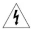
The lightning flash with arrowhead symbol, within an equilateral triangle, is intended to alert the user to the presence of uninsulated "dangerous voltage" within the product's enclosure that may be of sufficient magnitude to constitute a risk of electric shock.

The exclamation point within an equilateral triangle is intended to alert the user to the presence of important operating and maintenance (servicing) instructions in the literature accompanying the appliance.

The “Caution, hot surface” symbol indicates that the marked item may be hot and should not be touched.

The “ON/OFF” symbol indicates connection to or disconnection from the mains, at least for mains switches.
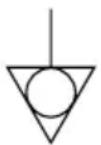
The “Equipotentiality” symbol identifies the terminals connected each other. The potential of various parts of equipment or of a system is equalized.

The “Alternating current” symbol indicates that the equipment is suitable for alternating current only.
When you dispose of the unit or accessories, you must obey the law in the relative area or country and/or regulation in the relative hospital.
WARNING:
Install and use this appliance in accordance with the operation manual for safety and EMC (Electromagnetic Compatibility). If it is not installed and used in accordance with the operation manual, it may cause interference to other equipment and/or other risk.
To prevent fire or shock hazard, do not expose this appliance to rain or moisture.
This appliance must be earthed.
In Europe, use the AC power cord according to the recommendations as below, in order to comply with EN60601-1 and EN60950.
Connect to the 230V receptacle of the room or the host equipment.
The AC power cord should be VDE approved and consist of core size 1mm ^2 or bigger, length 2.5m or shorter cord with IEC320/C13 type, 250V 10A or higher rating connector and CEE(7)VII type or IEC 320-2.2/E type, 250V 10A or higher rating plug.
Use the USB cable according to the recommendations as below, in order to comply with EN60601-1-2.
The USB cable with appropriate plug should be 2 m long or shorter, comply with USB 2.0 standard High speed requirements and USB IF (USB Implementers Forum) approved.
This product is to be employed with medical equipment, just for reference purpose, not for medical diagnostic purpose.
INSTRUCTIONS FOR MEDICAL USE
MEDICAL ELECTRICAL EQUIPMENT needs special precautions regarding EMC and needs to be installed and put into service according to the EMC information provided in the AC-COMPANYING DOCUMENTS.
Portable and mobile RF communications equipment can affect MEDICAL ELECTRICAL EQUIPMENT.
Technical description
List of all cables and maximum length of the cable and transducers and other ACCECCORIES
| Maximum length | Reference page in this operation manual | |
| AC power cord | 2.5 m | This page, the previous pages for safety and page 22 for accessories |
| USB cable | 2 m | This page, the previous pages for safety and page 22 for accessories |
| Thermal paper | Page 3 for thermal paper, Page 22 for accessories |
WARNING:
The use of ACCESSORIES, transducers and cables other than those specified, with the exception of transducers and cables sold by the manufacturer of the Model P93DW/P93DE as replacement parts for internal components, may result in increased EMISSIONS or decreased IMMUNITY of the Model P93DW/P93DE.
WARNING:
The Model P93DW/P93DE should not be used adjacent to or stacked with other equipment and that if adjacent or stacked use is necessary, the Model P93DW/P93DE should be observed to verify normal operation in the configuration in which it will be used.
| Guidance and manufacturer's declaration - electromagnetic emissions | ||
| The Model P93DW/P93DE is intended for use in the electromagnetic environment specified below. The customer or user of the Model P93DW/P93DE should assure that it is used in such an environment. | ||
| Emission test | Compliance | Electromagnetic environment - guidance |
| RF emissions CISPR 11/EN 55011 | Group 1 | The Model P93DW/P93DE uses RF energy only for its internal function. Therefore, its RF emissions are very low and are not likely to cause interference in nearby electronic equipment. |
| RF emissions CISPR 11/EN 55011 | Class B | The Model P93DW/P93DE is suitable for use in all establishments, including domestic establishments and those directly connected to public low-voltage power supply network that supplies buildings used for domestic purpose. |
| Harmonic emissions IEC/EN 61000-3-2 | Class A | |
| Voltage fluctuations / flicker emissions IEC/EN 61000-3-3 | Complies | |
| Guidance and manufacturer's declaration - electromagnetic immunity | |||
| The Model P93DW/P93DE is intended for use in the electromagnetic environment specified below. The customer or user of the Model P93DW/P93DE should assure that it is used in such an environment. | |||
| Immunity test | IEC/EN 60601 test level | Compliance level | Electromagnetic environment - guidance |
| Electrostatic discharge (ESD) IEC/EN 61000-4-2 | ±6 kV contact ±8 kV air | ±6 kV contact ±8 kV air | Floors should be wood, concrete or ceramic tile. If floors are covered with synthetic material, the relative humidity should be at least 30%. |
| Electrical fast transient/burst IEC/EN 61000-4-4 | ±2 kV for power supply lines ±1 kV for input /output lines | ±2 kV for power supply lines ±1 kV for input /output lines | Mains power quality should be that of a typical commercial or hospital environment. |
| Surge IEC/EN 61000-4-5 | ±1 kV differential mode ±2 kV common mode | ±1 kV differential mode ±2 kV common mode | Mains power quality should be that of a typical commercial or hospital environment. |
| Voltage dips, short interruptions and voltage variations on power supply input lines IEC/EN 61000-4-11 | < 5% UT (>95% dip in UT) for 0,5 cycle 40% UT (60% dip in UT) for 5 cycles 70% UT (30% dip in UT) for 25 cycles < 5% UT (>95% dip in UT) for 5 sec. | < 5% UT (>95% dip in UT) for 0,5 cycle 40% UT (60% dip in UT) for 5 cycles 70% UT (30% dip in UT) for 25 cycles < 5% UT (>95% dip in UT) for 5 sec. | Mains power quality should be that of a typical commercial or hospital environment. If the user of the Model P93DW/P93DE requires continued operation during power mains interruptions, it is recommended that the Model P93DW/P93DE be powered from an uninterruptible power supply or a battery. |
| Power frequency (50/60 Hz) magnetic field IEC/EN 61000-4-8 | 3 A/m | 3 A/m | Power frequency magnetic fields should be at levels characteristic of a typical commercial or hospital environment. |
| NOTE UT is the a.c. mains voltage prior to application of the test level. | |||
| Conducted RF IEC/EN 61000-4-6Radiated RF IEC/EN 61000-4-3 | 3 Vrms150 kHz to 80 MHz3 V/m80 MHz to 2,5 GHz | 3 Vrms3 V/m | Portable and mobile RF communications equipment should be used no closer to any part of the Model P93DW/P93DE, including cables, than the recommended separation distance calculated from the equation applicable to frequency of the transmitter.Recommended separation distance d=1,2 d=1,2 80 MHz to 800 MHz d=2,3 800 MHz to 2,5 GHzwhere P is the maximum output power rating of the transmitter in watts (W) according to the transmitter manufacturer and d is the recommended separation distance in meters (m).Field strengths from fixed RF transmitters, as determined by an electromagnetic site survey, ^a should be less than the compliance level in each frequency range. ^b Interference may occur in the vicinity of equipment marked with the following symbol: |
| NOTE1. At 80 MHz and 800 MHz, the higher frequency range applies.NOTE2. These guidelines may not apply in all situations. Electromagnetic propagation is affected by absorption and reflection from structures, objects and people. | |||
| ^a Field strengths from fixed transmitters, such as base stations for radio (cellular/cordless) telephones and land mobile radios, amateur radio, AM and FM radio broadcast and TV broadcast cannot be predicted theoretically with accuracy. To assess the electromagnetic environment due to fixed RF transmitters, an electromagnetic site survey should be considered. If the measured field strength in the location in which the Model P93DW/P93DE is used exceeds the applicable RF compliance level above, the Model P93DW/P93DE should be observed to verify normal operation. If abnormal performance is observed, additional measures may be necessary, such as reorienting or relocating the Model P93DW/P93DE. ^b Over the frequency range 150 kHz to 80 MHz, field strength should be less than 3 V/m.Recommended separation distances between Portable and mobile RF communications equipment and the Model P93DW/P93DE | |||
| The Model P93DW/P93DE is intended for use in the electromagnetic environment in which radiated RF disturbances are controlled. The customer or user of the Model P93DW/P93DE can help prevent electromagnetic interference by maintaining a minimum distance between portable and mobile RF communications equipment (transmitters) and the Model P93DW/P93DE as recommended below, according to the maximum output power of the communications equipment. | |||
| Rated maximum output power of transmitter W | Separation distance according to frequency of transmitter m | ||
| 150 kHz to 80 MHz d=1,2 | 80 MHz to 800 MHz d=1,2 | 800 MHz to 2,5 GHz d=2,3 | |
| 0,01 | 0,12 | 0,12 | 0,23 |
| 0,1 | 0,38 | 0,38 | 0,73 |
| 1 | 1,2 | 1,2 | 2,3 |
| 10 | 3,8 | 3,8 | 7,3 |
| 100 | 12 | 12 | 23 |
| For transmitters rated at maximum output power not listed above, the recommended separation distance d in meters (m) can be estimated using the equation applicable to the frequency of the transmitter, where P is the maximum output power rating of the transmitter in watts (W) according to the transmitter manufacturer. NOTE1. At 80 MHz and 800 MHz, the separation distance for higher frequency range applies. NOTE2. These guidelines may not apply in all situations. Electromagnetic propagation is affected by absorption and reflection from structures, objects and people. | |||
1 CONTENTS
1 CONTENTS ...... 1
2 PRECAUTIONS 2 - 4
3 UNPACKING...... 5
4 FEATURES AND FUNCTIONS 6 - 7
Front Panel 6
Rear Panel 7
5 INSTALLATION OF PAPER 8 - 9
6 EXAMPLE OF CONNECTION / SETTING OF SWITCHES.... 10
7 PRINTING 11 - 12
8 ADJUSTMENT OF PRINT PICTURE .... 13 - 15
9 ERROR DISPLAY 16 - 18
10 STATUS AND MODES 19
11 USE OF CLEANING PAPER 20
12 MAINTENANCE.... 21
13 SPECIFICATIONS 22
2 PRECAUTIONS
In the interest of safety, please observe the following precautions:
POWER REQUIREMENT
This digital monochrome printer is designed for operation on 100-240V AC 50/60Hz. Never connect to any outlet or power supply having a different voltage or frequency.
WARNING : THIS APPARATUS MUST BE EARTHED. AVERTISSEMENT : CET APPAREIL DOIT ETRE MIS A LA TERRE.
This equipment is classified as class I, according to the type of protection against electric shock.
PROTECTIVE MEASURES
IF ABNORMALITIES ARISE, ...
Use of the unit during emission of smoke or abnormal sounds (without adopting countermeasures) is dangerous. In such a case, unplug the power cord from the source outlet immediately, and request maintenance services from the sales dealer.
NEVER INSERT ANY OBJECT INTO THE UNIT
Foreign objects of any kind inserted into this unit constitute a safety hazard and can cause extensive damage. If any object should be inserted into the unit, unplug the power cord, then contact the sales dealer.
DO NOT PLACE ANYTHING ON THE UNIT
Heavy objects placed on the unit can cause damage or obstruct proper ventilation.
PROTECT THE POWER CORD
Damage to the power cord may cause fire or shock hazard. When unplugging, hold by the plug only and remove carefully.
Never put heavy objects on the power cord. The cord may be damaged causing a fire or electric shock.
DO NOT PLACE WATER CONTAINERS ON THE UNIT
Do not place flower vases, and other water-holding containers on the unit. If, for some reason, water seeps to the inside of the unit, unplug the power cord from the source outlet, and contact the sales dealer. If used without corrective measures, the unit may be damaged.
DO NOT REMOVE THE CABINET
Touching internal parts is dangerous or may lead to malfunction. Contact the sales dealer to carry out internal checks and/or adjustments. Before opening the cover to clear a paper jam, etc., be sure to disconnect the power cord plug.
DO NOT ATTACH A SCREW MORE THAN 6MM LONG ON THE BOTTOM
If a screw more than 6 mm long is attached on the bottom of the printer, it may cause internal damage.
PROTECT AGAINST DEW FORMATION
In extremely cold regions, if the unit is moved quickly from an extremely cold place to a warmer one, dew is likely to be formed. If dew is formed, printing is not possible.
The operating ambient temperature range is 5°C-40°C (41°F-104°F), and humidity of 20-80%.
BE CAREFUL AROUND PRINT PAPER EXIT SLOT
Do not insert your hand or any material into the paper exit slot during printing.
Do not touch the cutter blade inside the paper exit slot.
Otherwise, your finger will be injured.
DO NOT TOUCH THE THERMAL HEAD AND CUTTER
Do not touch the thermal head (located inside the unit) and the cutter blade.
The thermal head is heated to high temperature.
This may cause injury.
INSTALLATION LOCATIONS
MAINTAIN GOOD VENTILATION
Ventilation slots and holes are provided on sides of this unit.
Place the unit on a hard and level surface and locate at least 4" (10cm) from walls to ensure proper ventilation.
UNSUITABLE LOCATIONS
Avoid shaky places or hot-springs areas where hydrogen sulfide and acidic ions are likely to be generated.
PLACES WITH HIGH HUMIDITY AND DUST
Do not place the unit at locations with high humidity and/or dust. They can cause extensive damage.
Avoid places where the unit is likely to contact oily fumes and vapors.
PLACES LIKELY TO BE EXTREMELY HOT
Places exposed to direct sunlight, or near heating appliances can attain extremely high temperatures, which may deform the cabinet, or can become a prime cause of damage.
SET THE UNIT ON A FLAT SURFACE
Do not use the unit when inclined ±20^ in vertical or horizontal direction, or in an unstable place.
Uneven surfaces may disturb paper feeding or ventilation, or affect the performance of the unit.
Many plastic components are used in the unit.
Coat flaking and deformation are likely to occur if the unit is wiped with chemical dusters, benzine, thinner or any other solvent, if rubber or PVC items are left in contact with the unit for extended duration, or if the unit is sprayed with insecticide.
CARE OF THE CABINET
Unplug and clean with a soft cloth slightly moistened with a mild soap and water solution. Allow to dry completely before operating. Never use petroleum base solutions or abrasive cleaners.
HEAD ABRASION
The thermal head, like the video head, wears out.
When it is abraded, it becomes hard to print out fine details of the picture. In such a case, it is necessary to replace the thermal head. Consult with the sales dealer for replacing the head.
WHEN A DEFECT IS FOUND
If you detect smoke or other smell from the unit, disconnect immediately the power cord plug from a wall socket and ask the agent for repair. It may be dangerous to operate the unit under these conditions.
CONNECTION DEVICES
Read thoroughly "Operating Precautions" of the instruction booklets for the devices connected with the digital monochrome printer.
Do not disconnect the power cord during printing.
CAUTION ON RELOCATING
When transporting this unit, make sure it is not likely to be subjected to impacts. They can be a prime cause for damage. Further, make sure to disconnect the power cord from the power outlet, and the cables from the connected devices.
UNPLUG THE POWER CORD DURING A LONG ABSENCE
Turn off the MAIN power switch and unplug the power cord during a long absence.
THERMAL PAPER
■ Thermal papers listed in the page of SPECIFICATIONS are available.
When the remaining length of the paper is about10" (25cm), a color belt appears at the paper end. Prepare for replacement of the paper. If the remaining paper length is less than 10" (25cm), printing becomes uneven due to the uneven paper core surface.
■ When the Printed paper is touched by wet hand, the print may be discolored.
When the paper runs out during printing, the printing operation stops and "EP" is displayed by the indicator on the front panel. Install new paper at this time.
■ Store the printed paper in a place with low humidity free from a direct sunlight.
If the paper absorbs non-volatile organic solvents (alcohol, ester, katone, etc.) the print may be discolored.
Particularly, if the paper comes in contact with soft vinyl chloride such as a transparent tape, it quickens discoloration.
■ Do not use paper other than the specified types.
- Immediately after the paper is replaced, 2-3 images may be printed with a blank part due to hand's dust or oil.
- Avoid direct sunlight or places near heaters, etc., and store the paper in a place with 30°C (86°F) or lower temperature and 35-80% RH.
■ When the paper is rapidly transferred from a cool place to a hot place, a vapor or a dew is generated on the paper surface causing paper jam or degraded printing quality.
■ A finger print or dust on the paper surface may degrade the printing quality.
Note:
Mitsubishi brand thermal paper is specially treated with an anti-static coating against thermal head damage caused by static-electricity discharge.
The use of non-treated paper may cause premature head failure in your product.
SAFETY TECHNICAL CHECKS
Periods: According to the recommendations of the manufacturer of medical device.
Scope: a) Visual check
Housing, cables, operator controls, readout device (displays, LED etc.), labels, accessories, instruction manual.
b) Function test
Performance check acc. instruction manual, also unity and applicability of set and accessory test.
c) Electrical check
Safety electrical test of the configuration in accordance with EN60601-1.
"In the interest of safety, avoid the handling of liquids beside the set."
RESPONSIBILITY OF THE MANUFACTURER
The manufacturer, assembler, installer or importer considers himself responsible for the effects on safety, reliability and performance of the EQUIPMENT only if:
- assembly operations, extensions, re-adjustments, modifications or repairs are carried out by persons authorized by him, and
– the electrical installation of the relevant room complies with the IEC requirements
– the EQUIPMENT is used in accordance with the instructions for use.
- Any service after expiration of the warranty period will be chargeable. Consult your dealer for advice.
TECHNICAL DESCRIPTION
The supplier will make available on request such circuit diagrams, component part lists, descriptions, calibration instructions or other information which will assist the USER's appropriately qualified technical personnel to repair those parts of the EQUIPMENT which are classified by the manufacturer as repairable.
The use of ACCESSORY equipment not complying with the equivalent safety requirements of this equipment may lead to a reduced level of safety of the resulting system. Consideration relating to the choice shall include:
– use of the accessory in the PATIENT VICINITY
– evidence that the safety certification of the ACCESSORY has been performed in accordance to the appropriate EN60601-1 and/or EN60601-1-1 harmonized national standard.
The transportation and storage environmental conditions are:
Temperature : -20°C - +60°C (-4°F - +140°F)
Humidity : 90%RH or less at 40°C (104°F)
Note : The above transportation environmental conditions indicate the storage environmental conditions during transport.
3 UNPACKING
Take the unit out of the box by the following procedures. Make sure to check the contents.
| 1 Open the top of the box. | 3 Take the unit out of the box carefully. |
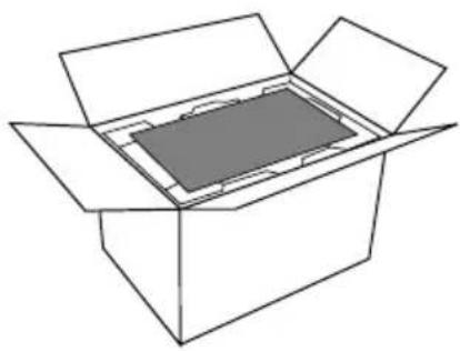 | • Make sure to keep the unit horizontal. |
| 2 Remove the cushion above the unit. | 4 Unwrap the unit. |
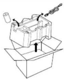 | 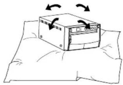 |
Accessories
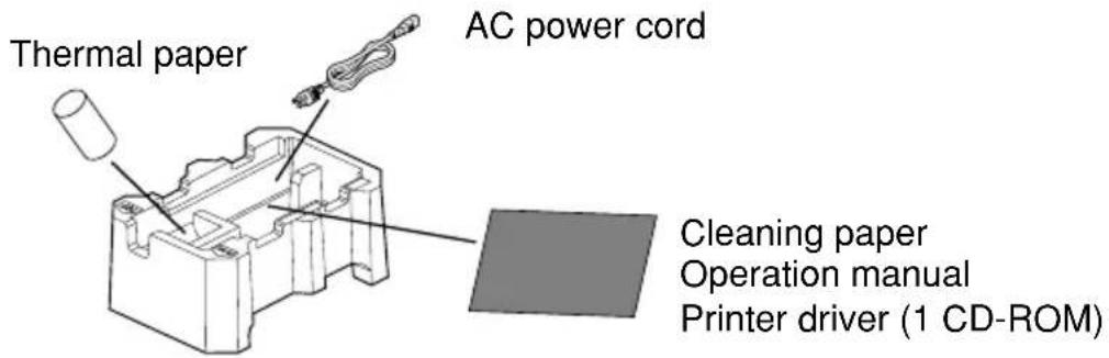
4 FEATURES AND FUNCTIONS
Front Panel
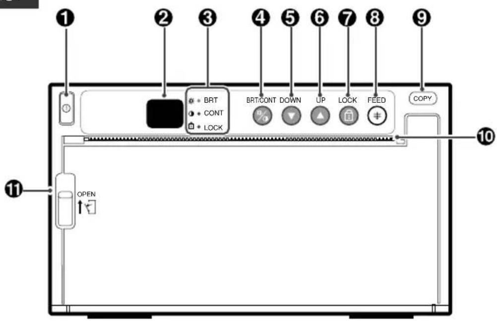
| Name | Function | Reference Page | |
| 1 | Power switch Turns on/off the power. | 11·20 | |
| 2 | Indicator | Displays stand-by, functions and error messages. | 11·14·16-19 |
| 3 | Indicator (BRT/CONT/LOCK) | Displays the settings of brightness, contrast and button function lock | 10·13 |
| 4 | BRT(brightness)/CONT(contrast) button | Makes fine adjustments of the brightness and contrast of the print image. | 13 |
| 5 | DOWN button | Press to decrease the setting value. | 14 |
| 6 | UP button | Press to increase the setting value. | 14 |
| 7 | LOCK button | Locks the button functions | 15 |
| 8 | FEED button 12 | Press to feed the paper. | |
| 9 | COPY button | Press to print additional copies of the previous print-out. | 11 |
| 10 | Print exit/Cutter | Printed paper will come out through this slot./ Cut the printed paper here. | 8·11·20 |
| 11 | Lever | Switch to open the door. | 8·20 |
Rear Panel
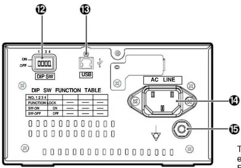
POTENTIAL EQUALIZATION TERMINAL
This is used to equalize the potential of the equipment connected to this unit.
For details refer to the installation instruction of equipment to be connected.
| Name | Function | Reference Page | |
| 12 | DIP switch | Selects special functions. | 10 |
| 13 | USB terminal | Connects to the device equipped with USB interface such as personal computer. | 10 |
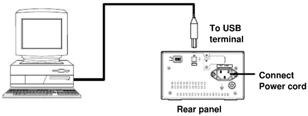
| 14 | Power terminal (AC LINE) | Connect the power cord to this terminal. | 10 |
| 15 | Potential equalization terminal | Makes the connected equipment potential equal. | - |
5 INSTALLATION OF PAPER
■ Moisture, fingerprints or dust on the paper surface may cause a noise at printing or deterioration in print quality. Set the paper by the following procedure to prevent adhesion of fingerprint or dust on the paper surface.
1 Open the door.
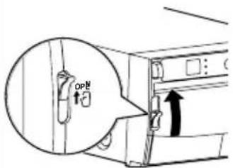
- Switch the lever located on the left side to the "OPEN" position.
■ The door opens.
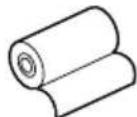
2 Load the paper roll.
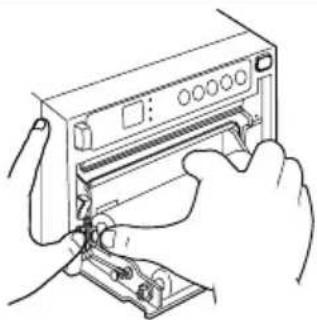
natural_image
Line drawing of hands inserting a device into a rack (no text or symbols)- Place the paper roll in the printer.
INCORRECT
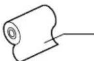
printing side
CORRECT
Note: The printing surface is the outside. Place the paper with the thermo-sensitive side (printing side) up. When the paper roll is placed inversely, images can not be printed.
3 Pull out the paper end.
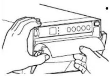
natural_image
Illustration of hands holding a device with a scroll (no text or symbols visible)- Pull out the first 15-20cm (6 in. - 9 in.) of the paper to remove any slack in the roll.
4 Close the door.
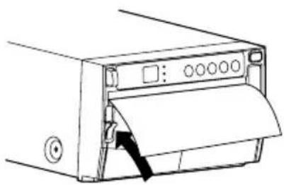
natural_image
Line drawing of a printer with paper roll and arrow indicating compression (no text or symbols)5 Cut the paper end.
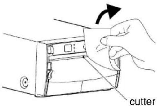
- Cut the paper end with the cutter by pulling the paper upwards against the cutter blade.
■ When setting the paper, observe the following precautions to prevent paper jam.
| Do not use defective paper. | |
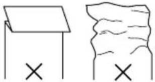 | ■ Do not use bent or wrinkled paper. |
Adjust the paper position correctly.
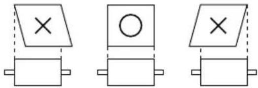
natural_image
Three schematic diagrams showing rectangular blocks with cross symbols and rectangles, no text or labels present.■ When the paper is fed out skewed from the print exit, adjust the paper position so that it is fed out straight.
Do not allow slack in the paper roll.
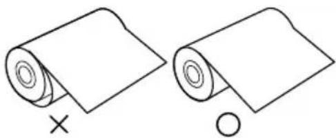
natural_image
Two rolled-up paper sheets, one with a cross mark and the other with a circle (no text or symbols)■ Set the paper tightly to remove any slack.
If the side of the print paper is uneven or the core is sticking out, the amount of paper feeding after printing may vary.
When the side of paper is uneven or the core is sticking out, install the print paper after making the paper side even.
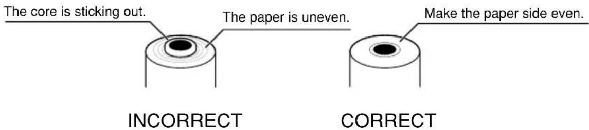
CAUTION
- Keep the high-density paper away from fingerprint, dust or moisture when storing it.
- Do not touch the rubber roller. Do not stain or damage the roller surface.
- Do not touch the thermal head (located behind the cutter). When printing, the thermal head is heated to high temperature.
- Do not touch the cutter blade.
6
EXAMPLE OF CONNECTION / SETTING OF SWITCHES
Connecting to various equipment with USB interface such as medical equipment and personal computer.
Connection
Connect the digital monochrome printer with PC or medical equipment through a USB cable.
Personal computer or medical equipment
Setting of Switches
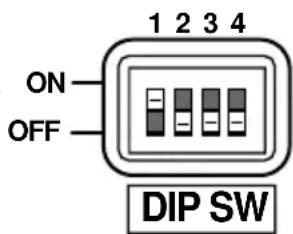
Set the DIP switches on the rear panel.
- When setting the switch No. 1 to ON, DOWN, UP, and LOCK buttons will be locked. (The functions will not be available.) At this time, the LOCK indicator illuminates.
Set the switches other than No. 1 to OFF.
Installing printer driver
Printer driver is required to print the data from a personal computer connected with this printer. The printer driver for Windows®2000/XP is supplied with this printer.
Refer to the "Read me" for installing the printer driver in the CD-ROM supplied with this unit.
How to open the ReadMe file
1 Install the CD-ROM in the CD-ROM drive on your PC.
2 Double-click on the CD-ROM icon.
3 Double-click on the ReadMe_E.pdf.
Adobe® Reader® or Adobe® Acrobat® Reader® is required to open ReadMe_E.pdf file. You can download Adobe Reader and Acrobat Reader free from the Web site of Adobe Systems Incorporated (http://www.adobe.com/products/acrobat/).
4 Install the printer driver by following the instruction in the file.
Microsoft® Windows®2000, and Windows® XP are the registered trademarks of Microsoft Corporation in the U.S.A and other countries.
Adobe, Acrobat Reader and Adobe Reader are registered trademark of Adobe Systems Incorporated.
7 PRINTING
| 1 Turn on the power. | 3 Cut the printed paper. |
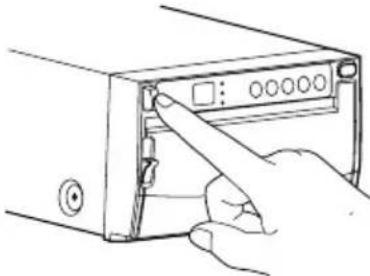 Press the POWER switch to turn on the power. Press the POWER switch to turn on the power. | 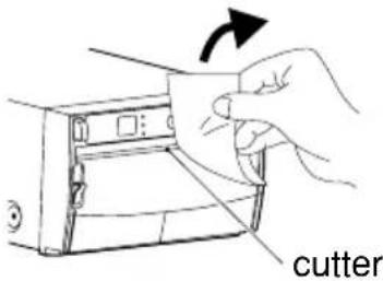 Cut the printed paper with the cutter by tearing off the paper in the upper right direction. Cut the printed paper with the cutter by tearing off the paper in the upper right direction. |
| 2 Print a picture displayed on the screen. | Do not pull the paper in the horizontal direction. The paper inside the unit may be displaced and printing may not be carried out correctly. |
| ■ Print a picture with an application software. The image data is transferred through USB interface. |
Copy Printing
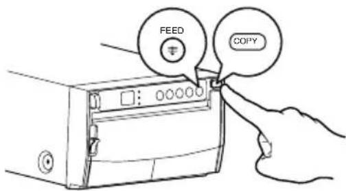
■ You can set the number of copies by pressing the COPY button on the front panel. (Setting range : 1 to 200)
You can copy the same picture as many times as you desire until a new image data is printed.
■ The set number of copy printing and the number of the remainings are displayed on the indicator as shown right.
■ The number of copy print setting is not memorized.
■ When pressing the UP button during copy printing, continuous printing is available.
Cancel of Copy Printing
■ When pressing the FEED button during copy printing, the copy printing is cancelled upon completion of the current copy.
| Indicator | Number of copy printing / remainings |
| 1-99 | 1 - 99 |
| 00-99. | 100 - 199 |
| 0.0. | 200 |
| C C | Continuous printing |
Paper Feeding
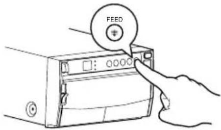
■ To feed the paper, press the FEED button on the front panel.
Precautions on Printing
■ When dark pictures are printed consecutively, the digital monochrome printer may become overheated and the indicator blinks.
In this case, wait for a while until the unit has cooled down.
■ Avoid pulling out or holding the paper during printing or copying to prevent paper jam.
Do not touch the paper until printing or copying finishes.
8
ADJUSTMENT OF PRINT PICTURE
Adjustment of Printer Brightness/Printer Contrast
■ You can make fine adjustment of printer brightness and printer contrast of the printed picture.
Control panel

- For adjustment, use the BRT/CONT button "BRT/CONT", UP button "UP" and DOWN button "DOWN".
1 Press the BRT/CONT button.
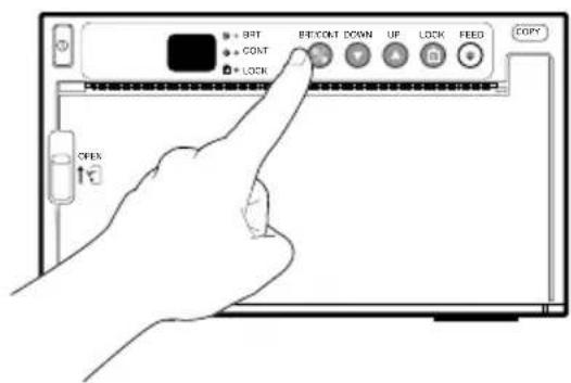
■ Press the BRT/CONT button "BRT/CONT" once to adjust the printer brightness.
• The BRT indicator lights up.
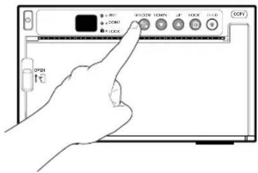
■ Press the BRT/CONT button "BRT/CONT" twice to adjust the contrast.
• The CONT indicator lights up.
| 2 Change the setting. | 3 Store the set value. | |
 | • Press the UP button to increase the value. | ■ By pressing the BRT/CONT button again, the setting value is memorized.■ The memorized value will not be lost even when the power is turned off. |
 | • Press the DOWN button to decrease the value. | |
■ The setting value is displayed by the indicator.(example)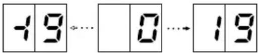 ■ Setting range is -19 to +19. ■ Setting range is -19 to +19. | ||
Automatic restoration to the standby status from the adjustment or setting mode
- When left without any operation of buttons, and switches under the following conditions for more than 20 seconds, this unit automatically returns to the standby status (Indicator display: 08) In this case, the newly set value is not memorized and the setting goes back to the value that was set before change.
- While adjusting the printer brightness or printer contrast
Resetting the values
■ You can reset the values of printer brightness and printer contrast.
1 Turn off the power.
2 While pressing the FEED button, turn on the power.
3 The display by the indicator changes from FC to 00 and the values are reset to the default setting.
Locking the button functions
■ You can lock the function of UP and DOWN buttons on the control panel.
To lock the button functions
1 Hold the LOCK button for approx. 1 second until a "Peep" sounds.
2 The functions of UP and DOWN buttons are locked and the LOCK indicator illuminates.
When the UP or DOWN button is pressed on this status, "E is displayed on the indicator. Whenever the BRT/CONT buttons is pressed, each set value of brightness and contrast can be checked.
To unlock the button functions
1 Hold the LOCK button for approx. 1 second until a "Peep" sounds.
2 The functions of UP and DOWN buttons are unlocked and the LOCK indicator goes off.
If the DIP switch No. 1 is set to ON, this function is not available. (The LOCK button becomes invalid.)
In case of an error in the unit during operation, you are warned by an alarm tone or the LED indicator.
| Cause/Error display | Symptom/Remedy |
| 1 Overheat | [Symptom]When the head gets overheated, the indicator blinks.When overheat occurs while more than one copy is being processed, printing starts as soon as the error is solved.If some images are waiting to be processed, the following buttons function as described below.COPY buttonEach time the COPY button is pressed, the number displayed by the indicator increases as 2→3→4.After the error is solved, copy printing starts automatically.FEED buttonWhen the number of copies has been set to more than one, outstanding copies are cancelled.When no image remains to be processed, the buttons are valid during overheat status. After the error is solved, copy printing starts automatically. |
| [Remedy]Wait until the head cools down. | |
2 No paper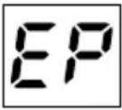 | [Symptom]When the paper runs out or the paper is not installed, printing becomes impossible and an alarm tone is heard.In this case, all the buttons become invalid.If this error occurs while more than one copy is being printed or there are images waiting to be processed, printing is cancelled at the occurrence of the error. |
| [Remedy]Install a new roll of paper according to "5. INSTALLATION OF PAPER" on page 8.When the paper is correctly installed while the printing of more than one copy has been suspended or there are images waiting to be processed, an alarm tone is heard. Then, the paper is fed automatically about 15 cm and printing resumes.After the error is resolved, the unit resumes printing from the interrupted image and finishes printing all the outstanding images. |
| Cause/Error display | Symptom/Remedy |
3 Button input error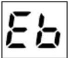 | [Symptom]The button becomes invalid and an alarm tone is heard in the following cases.During adjusting the printer brightness or the printer contrast, theUPbutton is pressed exceeding the upper limit value (LED display :19) or theDOWNbutton is pressed exceeding the lower limit value (LED display :-18TheUPorDOWNbutton is pressed when the button functions are locked with theLOCKbutton or the DIP switch No. 1.The indicator displays “E8for one second and return to the status before the error occurred. |
4 Door error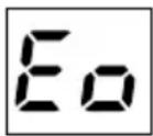 | [Symptom]When the door opens, an alarm tone is heard.The indicator displays "E" for one second.In this case, all the buttons and switches become invalid.If this error occurs while more than one copy is being printed, printing is cancelled at the occurrence of the error. |
| [Remedy]Close the door.When the door is closed while the printing of more than one copy is being printed, an alarm tone is heard.After the error is resolved, the unit resumes printing from the interrupted image and finishes printing all the outstanding images. |
| Cause/Error display | Symptom/Remedy |
5 Gear lock error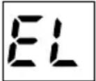 | [Symptom]When the thermal head does not automatically go down at the start of printing or paper feeding, an alarm tone is heard.When the thermal head does not automatically go up at the end of printing or paper feeding, an alarm tone is heard.The indicator displays "EL" and all the buttons become invalid.If this error occurs while more than one copy is being printed or there are images waiting to be processed, printing is cancelled at the occurrence of the error. |
| [Remedy]Turn the power off. Then turn it on again.Printing of the interrupted image or all the images saved in the memory that are waiting to be processed is cancelled. |
10
STATUS AND MODES
| Set state/Mode | LED display | Contents of LED display |
| Power off | Power off | |
| Stand-by | 00 | |
| During data receiving | 00 | During data receiving |
| Print state | 1-9900-99.0.0.CC | Remaining number of copies /number of copies1 to 99100 to 199200Continuous copy printing |
| Printer brightness mode | -19 - 19 | Fine adjustment of the picture brightness |
| Printer contrast mode | -19 - 19 | Fine adjustment of the picture contrast |
| Error detect state | EP | No paper |
| Eb | Button input error | |
| Eo | Door is open. | |
| EL | Gear lock |
11 USE OF CLEANING PAPER
When the thermal head is dirty with dust, etc., white spots or stripes may appear on the print. In this case, clean the thermal head by the following procedure BY USING THE SUPPLIED CLEANING PAPER.
| 1 Turn on the power. | 4 Close the door. | ||
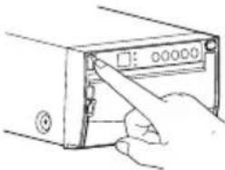 | ■Press the POWER switch to turn on the power. | 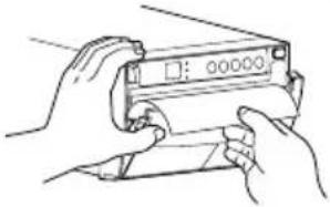 | ■Close the door without taking out the cleaning paper. |
| 2 Open the door. | |||
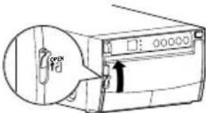 | ■Switch the left side lever to the OPEN position.■The door opens. | 5 Press the FEED button. | |
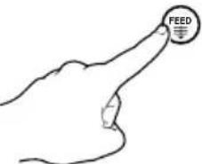 | ■Keep pressing the FEED button until you hear a beep. | ||
| 3 Insert the cleaning paper. | |||
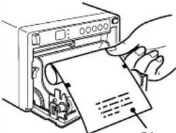 | ■Roll the cleaning paper and install into the set. | 6 Take out the cleaning paper. | |
| Cleaning paper | 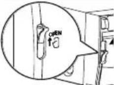 | ■Open the door.■Take out the cleaning paper. | |
| Red mark | ■Adjust the red mark on the cleaning paper parallel to the platen roller. | 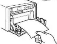 | ■Do not pull out the cleaning paper while the door is closed. |
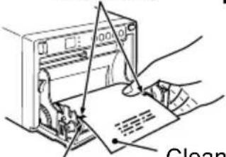 | |||
| Platen roller | Cleaning paper | 7 Repeat the steps 3-6 by 2 or 3 times, and print 1-2 sheets to verify the cleaning effect. | |
CAUTION
• It is recommended that after printing 10 rolls of paper the unit be cleaned using the supplied cleaning paper.
• If the symptom of the dirty head is not corrected even after cleaning, your set needs repairing, contact your dealer.
- Do not pull out the sheet and the cleaning paper while the door is closed.
This may cause extensive damage to the unit.
- Never use other cleaning papers. It may cause damage to the thermal head.
- This cleaning paper should be used only for cleaning the thermal head. Do not use it for other purpose.
12 MAINTENANCE
Turn off the power for maintenance.
Maintenance of Main Unit
Wipe off stains of the front panel with a soft cloth.
When the panel is heavily stained, wipe with a cloth moistened with neutral cleanser diluted by water and finish with a dry cloth.
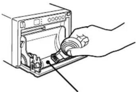
Maintenance of Rubber Roller
When the rubber roller is dirty with dust, etc., a blank spot may appear on the print.
In this case, eliminate the dust on to the rubber roller with a blower or a brush.
The regular cleaning using a lint-free cloth, etc., which is moistened with ethyl alcohol is recommended.
natural_image
Line drawing of a hand inserting a plug into a device casing (no text or symbols)Rubber roller
Cleaning of Thermal Head
When the thermal head is dirty with dust, etc., white spots or stripes may appear on the print.
In this case, clean the thermal head according to "11. USE OF CLEANING PAPER".
Note: After installation of new roll of paper, dust on the paper will generally require 2 to 3 prints to be made before the dust is eliminated.
13 SPECIFICATIONS
Type: Digital Monochrome Printer
Model: P93DW/P93DE
Power supply and
power consumption: 100-240V AC, 50/60Hz, 1.5 - 0.8A
Connection terminal: USB interface (Series "B" receptacle)
Hi-Speed USB (Ver. 2.0) supported
Resolution: 1280 x 1280 pixels (Standard)
(Max. 1280 x 5760 pixels)
Gradation: 256 gradations
Printing speed: 5.0 sec (Standard)
Print size: 4" x 4" (100 mm x 100 mm) (Standard)
(Max. 4" x 17.7" (100 mm x 450 mm))
Operating conditions: Temperature 41 - 104°F (5-40°C)
Humidity 20 - 80% RH (No dewing)
External dimensions: 6.1" x 3.5" x 10.1" (154mm x 89.5mm x 256mm); W x H x D
Weight: 6.2 lbs (2.8 kg)
Standard accessories: AC power cord .... 1 piece
Thermal paper KP65HM-CE 1 roll
Cleaning paper 1 sheet
Printer driver 1 CD-ROM
Optional accessory: Thermal paper KP65HM-CE, KP65H-CE, KP61S-CE,
KP61B-CE, KP91HG-CE
SERVICE INFORMATION
Before requesting service please review this operation manual to correct minor complaints. If you are unable to correct the problem, consult your MITSUBISHI Dealer or MITSUBISHI Service Department.
DO NOT ADJUST ANY CONTROLS NOT DESCRIBED IN THIS OPERATION MANUAL. DO NOT REMOVE THE PROTECTIVE ENCLOSURE OF THIS UNIT.

MITSUBISHI ELECTRIC
MITSUBISHI DIGITAL ELECTRONICS AMERICA, INC.
9351 Jeronimo Road, Irvine, CA 92618
Phone 949-465-6000
Mitsubishi Electric Europe B.V.
UK Branch
Travellers Lane, Hatfield, Herts. AL10 8XB, England, U.K.
Phone (0) 1707 276100 FAX (0) 1707 278755
German Branch
Gothaer Strasse 8, 40880 Ratingen ; Postfach 1548, 40835 Ratingen ; Germany
Phone 02102/486-9250 FAX 02102/486-7320
French Branch
25, Boulevard des Bouvets - 92741 NANTERRE cedex
Phone (01) 55.68.55.00 FAX (01) 55.68.57.31
Italian Branch
Via Paracelso 12, 20041 Agrate Brianza, (Milano) Italy
Phone (039) 60531 FAX (039) 6057694
Benelux Branch
Spanish Branch (Barcelona)
Sucursal en españa
Ctra. Rubí, 76-80, 08190 Sant Cugat del Vallés
Ap. de Correos 420
BARCELONA (SPAIN)
Phone +34 93 565 3154 FAX +34 93 589 4388
Manufactured by Mitsubishi Electric Corporation
1 Zusho Baba, Nagaokakyo-City, Kyoto Japan
- DIGITAL MONOCHROME
- PRINTER
- WARNING:
- CAUTION:
- NOTE:
- Information:
- RISK OF ELECTRIC SHOCK DO NOT OPEN.
- INSTRUCTIONS FOR MEDICAL USE
- CONTENTS
- PRECAUTIONS
- POWER REQUIREMENT
- PROTECTIVE MEASURES
- IF ABNORMALITIES ARISE, ...
- NEVER INSERT ANY OBJECT INTO THE UNIT
- DO NOT PLACE ANYTHING ON THE UNIT
- PROTECT THE POWER CORD
- DO NOT PLACE WATER CONTAINERS ON THE UNIT
- DO NOT REMOVE THE CABINET
- DO NOT ATTACH A SCREW MORE THAN 6MM LONG ON THE BOTTOM
- PROTECT AGAINST DEW FORMATION
- BE CAREFUL AROUND PRINT PAPER EXIT SLOT
- DO NOT TOUCH THE THERMAL HEAD AND CUTTER
- INSTALLATION LOCATIONS
- MAINTAIN GOOD VENTILATION
- UNSUITABLE LOCATIONS
- PLACES WITH HIGH HUMIDITY AND DUST
- PLACES LIKELY TO BE EXTREMELY HOT
- SET THE UNIT ON A FLAT SURFACE
- CARE OF THE CABINET
- HEAD ABRASION
- WHEN A DEFECT IS FOUND
- CONNECTION DEVICES
- CAUTION ON RELOCATING
- UNPLUG THE POWER CORD DURING A LONG ABSENCE
- THERMAL PAPER
- SAFETY TECHNICAL CHECKS
- RESPONSIBILITY OF THE MANUFACTURER
- TECHNICAL DESCRIPTION
- UNPACKING
- Accessories
- FEATURES AND FUNCTIONS
- Front Panel
- Rear Panel
- POTENTIAL EQUALIZATION TERMINAL
- INSTALLATION OF PAPER
- Open the door.
- Load the paper roll.
- Pull out the paper end.
- Close the door.
- Cut the paper end.
- Adjust the paper position correctly.
- Do not allow slack in the paper roll.
- CAUTION
- 6
- EXAMPLE OF CONNECTION / SETTING OF SWITCHES
- Connecting to various equipment with USB interface such as medical equipment and personal computer.
- Connection
- Setting of Switches
- Installing printer driver
- How to open the ReadMe file
- PRINTING
- Copy Printing
- Cancel of Copy Printing
- Paper Feeding
- Precautions on Printing
- 8
- ADJUSTMENT OF PRINT PICTURE
- Adjustment of Printer Brightness/Printer Contrast
- Control panel
- Press the BRT/CONT button.
- Automatic restoration to the standby status from the adjustment or setting mode
- Resetting the values
- Locking the button functions
- To lock the button functions
- To unlock the button functions
- In case of an error in the unit during operation, you are warned by an alarm tone or the LED indicator.
- 10
- STATUS AND MODES
- USE OF CLEANING PAPER
- MAINTENANCE
- Turn off the power for maintenance.
- Maintenance of Main Unit
- Maintenance of Rubber Roller
- Cleaning of Thermal Head
- SPECIFICATIONS
- SERVICE INFORMATION
- MITSUBISHI ELECTRIC
- UK Branch
- German Branch
- French Branch
- Italian Branch
- Benelux Branch
- Spanish Branch (Barcelona)
Brand : MITSUBISHI
Model : P93DE
Category : Printer