
Turbo Esprit (1980) - Automobile Lotus - Free user manual and instructions
Find the device manual for free Turbo Esprit (1980) Lotus in PDF.


| Type de produit | Automobile |
| Marque | Lotus |
| Modèle | Turbo Esprit (1980) |
| Catégorie | Sportive |
| Longueur | 4 191 mm |
| Largeur | 1 861 mm |
| Hauteur | 1 115 mm |
| Empattement | 2 438 mm |
| Poids à vide | 1 205 kg |
| Moteur | 2.2 L 4 cylindres turbo |
| Puissance | 210 ch à 6 000 tr/min |
| Couple | 272 Nm à 4 500 tr/min |
| Alimentation | Essence (SP95) |
| Capacité du réservoir | 75 L |
| Transmission | Boîte manuelle 5 vitesses |
| 0-100 km/h | 5,5 secondes |
| Vitesse maximale | 245 km/h |
| Consommation moyenne | 12 L/100 km |
| Entretien | Vidange tous les 10 000 km, courroie tous les 50 000 km |
| Freins | Disques ventilés à l'avant, disques pleins à l'arrière |
| Direction | Crémaillère, assistée |
| Pneus | Avant 195/60 R15, Arrière 225/55 R15 |
| Capacité du coffre | 200 L |
| Nombre de places | 2 |
| Fiabilité | Pièces détachées disponibles via clubs et spécialistes |
Frequently Asked Questions - Turbo Esprit (1980) Lotus
User questions about Turbo Esprit (1980) Lotus
0 question about this device. Answer the ones you know or ask your own.
Ask a new question about this device
Download the instructions for your Automobile in PDF format for free! Find your manual Turbo Esprit (1980) - Lotus and take your electronic device back in hand. On this page are published all the documents necessary for the use of your device. Turbo Esprit (1980) by Lotus.
USER MANUAL Turbo Esprit (1980) Lotus
SERVICE NOTES
Lotus Cars Limited
Norwich, Norfolk, NR14 8EZ, England. Telex 97401
Telephone: (0953) 608000 Telefax: (0953) 606884
Publication Part No. A082T0327Z

Lotus Cars Ltd
June 1986
This publication has been designed primarily for Lotus Dealers, and will be updated by the issue of Service Bulletins to Lotus Dealers when necessary.
Lotus policy is one of continuous product improvement an right is reserved to alter specifications at any time without notice.
Whilst every care has been taken to ensure correctness of it is impossible to guarantee complete freedom from error or to accept liability arising from such errors or omissions herein contained shall affect your statutory rights.
CONTENTS
TURBO ESPRIT & ESPRIT S3 (Prior '88 M.Y.)
| Subject | Section |
| Vehicle Identification | See overleaf |
| Technical Data - Engine - Esprit S3 | TDA |
| - Engine - Turbo | TDB |
| - Vehicle | TDD |
| Body - Paint Procedure | BA |
| - Bodycare & Repair | BB |
| - Body Fittings | BD |
| Front Suspension - Prior to '85 M.Y. | CB |
| - '85 M.Y. onwards | CC |
| Rear Suspension | DB |
| Engine | EB |
| Engine Management - USA Turbo, carburettor (Prior to '86 M.Y.) | EMA |
| - Turbo HC, Dom/Exp '87 M.Y. onwards | EMC |
| - Esprit HC, '87 M.Y. onwards | EMD |
| Transmission | FB |
| Steering | HB |
| Brakes - Prior to '85 M.Y. | JB |
| - '85 M.Y. onwards | JC |
| Cooling System | KB |
| Fuel System - Esprit S3 | LA |
| - Turbo, Dom/Export | LB |
| - USA Turbo, Carburettor | LC |
| - USA Turbo, Fuel Injection (Bosch K Jetronic) | LD |
| Electrical - Esprit S3 & Turbo, Dom/Export | MB |
| - USA Turbo, Prior '86 M.Y. | MC |
| - USA Turbo, '86 M.Y. onwards | ME |
| Maintenance & Lubrication - Esprit S3 & Turbo, Dom/Export | OB |
| - USA Turbo | OC |
| Heater & Air Conditioning | PB |
| Clutch | QB |
| Interior Trim | VB |
VEHICLE IDENTIFICATION NUMBER
The Vehicle Identification Number (VIN) is stamped on a plate fixed to the right or left hand front wheelarch inside the front luggage compartment. This number is repeated on the right hand side of the chassis front frame, visible from within the right hand front wheelarch.

This number, together with the engine number (see TDA or TDB) should be quoted in all enquiries regarding the vehicle.
There are two variations of the VIN, one being for Domestic and export markets other than for the USA, which complies with European Economic Community (EEC) directives, and one for the USA which complies with requirements laid down by the National Highway Traffic Safety Association (NHTSA).
The seventeen characters of the VIN are coded as follows:
NOTES
- USA VIN character 6:
501 = Basic Elite 521 = Basic Eclat 701 = Basic Esprit
502 = Elite A/C 522 = Eclat A/C 702 = Esprit A/C
503 = Elite A/C & PAS 523 = Eclat A/C & PAS 701 Comm = Esprit Commemerative
504 = Elite Auto 524 = Eclat Auto 702 Comm = Esprit Comm. A/C
A/C & PAS A/C & PAS
- Seperate serial number sequences are used for the following groups of chassis market (character 12);
D
A,E,G,H,S
B,C,F,K
- For change point identification in Service Notes, Parts Lists and Service Bulletins, the following VIN characters ONLY will be quoted;
Domestic & Export - 5,6,12,14 to 17
USA - 4,12,14 to 17
Example A typical change point could be listed as follows;
82 D 1100 (Domestic Turbo 1100)
82 A/E/G/H/S 0341 (Export Turbo 0341)
F B/C/F/K 0265 (USA Turbo 0265)
Note that three numbers are needed to identify the single change point due to the different serial number sequences outlined in note 2.
If a dash is used in place of the chassis market letter code (e.g.
82 - 0341 or F - 0265), this is the change point for all markets in that serial number sequence not otherwise listed.
DOMESTIC & EXPORT

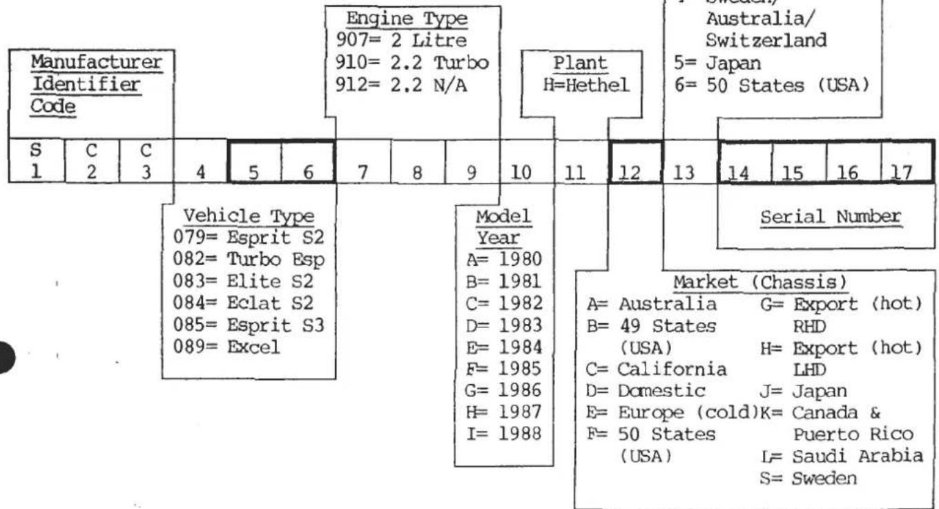
(fdlaag/1)
USA
(also Domestic & Export up to serial nos.;
Elite 1718 (Dom) 0236 (Exp), Eclat 1034 (Dom) 0205 (Exp), Esprit 0934 (Dom) 0307 (Exp))
![graph TD A["Manufacturer Identifier Code"] --> B["Engine 7=907"] A --> C["Engine 8=908"] A --> D["Engine 9=909"] A --> E["Engine 0=910"] A --> F["Engine 1=911"] A --> G["Engine 2=912"] H["Market (Chassis)"] --> I["A= Australia H= Export"] H --> J["B= 49 States (hot) LHD (USA) J= Japan"] H --> K["C=…](/content/2026/05/1021120/images/e97ddfa7ef1031eb8c957c00f826c97efc418b737587c4927bfe57f4a1e77b19.jpg)
(fdlaaf/1)
TECHNICAL DATA
SECTION TD A - ENGINE TYPE 907/912
Page
| Engine-Number | 2 |
| Engine Specification | 4 |
| Cylinder Head | 4 |
| Camshafts & Valve Mechanism | 5 to 7 |
| Crankshaft | 8 |
| Main Bearing Configuration | 8 |
| Flywheel | 9 |
| Connecting Rod | 9 |
| Gudgeon Pin | 9 |
| Piston & Liner | 9 to 11 |
| Lubrication System | 11 |
| Dellorto Carburettors | 12 |
| Zenith Carburettors | 13 |
| Ignition System | 14 |
| Distributor & Ignition Timing | 14/15 |
| Cooling System | 15 |
| Torque Loading Figures | 16 |
Before commencing work on any Lotus engine, first check the engine number and prefix letters to establish the engine specification. This number is stamped on the right hand rear of the cylinder block, above the starter motor, and is duplicated on the vehicle identification plate fixed to either the right or left hand inner wheelarch under the front bonnet.
Example
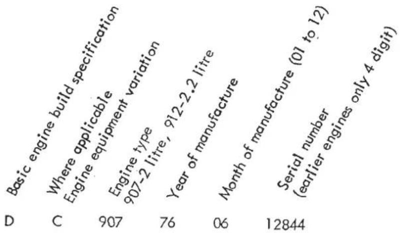
For the purpose of clarification in the TECHNICAL DATA SECTION ONLY, a specification number is allocated to various specifications as listed below. In some countries, prefix letters may differ from those listed, in which case reference should be made to the Lotus Distributor of that country for the relevant specification.
| FIRST PREFIX LETTER | SECOND PREFIX LETTER | REMARKS | TECHNICAL DATA SECTION SPEC. NO. |
| (907)D - Domestic Std.G - Domestic A/CJ - Domestic A/C & PAS | Single Prefix Letter Only. | 1974 | 1 |
| (907)F - U.S.A. Std.I - U.S.A. A/CK - U.S.A. A/C & PAS | Single Prefix Letter Only. | U.S.A. 1974 | 2 |
fdlaaa/5
| FIRST PREFIX LETTER | SECOND PREFIX LETTER | REMARKS | TECHNICAL DATA SECTION SPEC. NO. |
| (907)X - Domestic Std.W - Domestic A/CY - Domestic PASL - Domestic A/C & PASAML - Domestic A/C, PAS & Auto. | Single Prefix Letter Only. | 1975 | 3 |
| (907)P - U.S.A. Std.N - U.S.A. A/CZ - U.S.A. PASM - U.S.A. A/C & PAS | Single Prefix Letter Only. | U.S.A. 1975 | 4 |
| (907)C - EspritD - Elite/Eclat | C - Std.D - A/CZ - PASL - A/C & PASR - Auto.S - Auto. & A/CT - Auto. & PASM - Auto, A/C & PAS | EUROPEAN1976 - '80 | 5 |
| (907)A - EspritB - Elite/Eclat | C,D,Z,L,R,S,T,M,as for Spec. 5 | CALIFORNIA '76-'7949-STATES '76-'77 | 6 |
| (907)G - Elite/EclatH - Esprit | C,D,Z,L,R,S,T,M,as for Spec. 5 | 49-STATES1978-'80 | 7 |
| (907)J - EspritK - Elite/Eclat | C,D,Z,L,R,S,T,M,as for Spec. 5 | 1980 CALIFORNIA | 8 |
| (912)C - EspritD - Elite/Eclat/Excel | C,D,Z,L,R,S,T,M,as for Spec. 5 | EUROPEAN1980 ONWARDS | 9 |
| (912)C - EspritD - Excel | A - H.C.B - H.C. PASN - H.C. PAS & A/CP - H.C. & A/CY - H.C. PAS & A/C& Auto. | EUROPEANHIGH COMPRESSIONExcel 86 MY OptionEsprit Feb. 1987 | 10 |
fdlaat/1
ENGINE
| Max. rpm of engine | 7,000 | |
| No. of cylinders | 4 | |
| Firing order | 1,3,4,2 | |
| Capacity - type 907 | 1973cc (120.4 cu.in.) | |
| - type 912 | 2174cc (132.8 cu.in.) | |
| Stroke - type 907 | 69.2mm (2.72 in.) | |
| - type 912 | 76.2mm (3.00 in.) | |
| Bore (nominal) | 95.29mm (3.75 in.) | |
| Compression ratio | spec. 1,3,5 | 9.5 : 1 |
| spec. 2,4,6,7,8 | 8.4 : 1 | |
| spec. 9 | 9.44 : 1 | |
| spec. 10 | 10.9 : 1 | |
| Compression pressure | spec. 1,3,5,9 | 11.2 - 12.6 bar (165 - 185 lb/in 2 ) |
| spec. 2,4,6,7,8 | 10.2 - 11.6 bar (150 - 170 lb/in 2 ) | |
| spec. 10 | 11.5 - 13.0 bar (170 - 190 lb/in 2 ) | |
| Engine number location | On top of cylinder block adjacent to starter mounting |
Engine belt tensions - Toothed timing belt, using Burroughs gauge part number T000T0025J, 90 - 95 units cold (60°F/20°C) See Section EA.8.
| Total movement using moderate finger pressure on longest belt run. | ( - | Alternator 'V' belt | 12 mm (0.5 in.) | ( 1/2 in. ) |
| ( - | Compressor 'V' belt(A/C) | 9 mm (0.35 in.) | (3/8 in.) | |
| ( - | Power steering pump 'V' belt | 12 mm (0.5 in) | ( 1/2 in. ) |
CYLINDER HEAD
| Material | Aluminium alloy |
| Gasket | Steel / Asbestos |
| Combustion Chamber Depth (nos. 1 & 4) | 12.32-12.57mm(0.485-0.500 in) |
CAMSHAFTS AND VALVE TIMING
| Cam Type Designation | Identif. on shank between pulley & cam hsg. | Duration (crank degrees) | Inlet M.O.P. ATDC* | Cam Pulley Timing Dot | Exhaust M.O.P BTDC* | Cam Pulley Timing Dot | ||
| Spec.No. | Lift | |||||||
| 1 | D | 1 groove | 270° | 0.350" | 110° | red | 110° | red |
| 2,3,7 | C | plain | 272° | 0.340" | 110° | red | 110° | red |
| 4,6 | C | plain | 272° | 0.340" | 100° | blue | 110° | red |
| 5 | E | 2 groove | 260° | 0.344" | 102 1/2 " | yellow | 102 1/2 " | yellow |
| 8 | C | plain | 272° | 0.340" | 102 1/2 " | yellow | 110° | red |
| 9,10(EX) | 107 | 777.... | 252° | 0.378" | 104° | green | 104° | green |
| 10(IN) | 104 | 444.... | 272° | 0.410" | 104° | green | 104° | green |
FD1AAA/1
* All cams are symmetrical opening closing
VALVES
| Angle of valve seats and faces | 45° |
| Head diameter - Inlet | 35.47 - 35.65 mm (1.396 - 1.404 in.) |
| - Exhaust | 30.73 - 30.91 mm (1.210 - 1.217 in.) |
| Stem diameter - Inlet & Exhaust | 7.125 - 7.137 mm (0.2805 - 0.2810 in. |
| Stem clearance in guide - Inlet & exhaust | 0.008 - 0.046 mm (0.0003 - 0.0018 in. |
Valve clearance (cold)
| Spec. 1. ('D' Cams) - Inlet | 0.10 - 0.15 mm (0.004 - 0.006 in.) |
| - Exhaust | 0.20 - 0.25 mm (0.008 - 0.010 in.) |
| Spec 2,3,4,5,6,7,8,9- Inlet | 0.13 - 0.18 mm (0.005 - 0.007 in.) |
| - Exhaust | 0.25 - 0.31 mm (0.010 - 0.012 in.) |
Valve Seat Inserts
Bore in head:
| Standard | - Inlet | 37.235/37.260 mm. (1.466/1.467 in.) |
| - Exhaust | 34.290/34.315 mm. (1.350/1.351 in.) | |
| 0.025 mm (0.001 in) | - Inlet | 37.260/37.285 mm. (1.467/1.468 in.) |
| - Exhaust | 34.315/34.340 mm. (1.351/1.352 in.) | |
| 0.050 mm (0.002 in) | - Inlet | 37.285/37.315 mm. (1.468/1.469 in.) |
| - Exhaust | 34.340/34.365 mm. (1.352/1.353 in.) | |
| 0.127 mm (0.005 in) | - Inlet | 37.365/37.390 mm. (1.471/1.472 in.) |
| - Exhaust | 34.415/34.440 mm. (1.355/1.356 in.) |
Outside diameter of seat
| Standard | - Inlet | 37.325/37.350 mm. (1.4695/1.4705 in.) |
| - Exhaust | 34.380/34.405 mm. (1.3535/1.3545 in.) | |
| + 0.025 mm (0.001 in) | - Inlet | 37.350/37.375 mm. (1.4705/1.4715 in.) |
| - Exhaust | 34.405/34.430 mm. (1.1345/1.3555 in.) | |
| + 0.050 mm (0.002 in) | - Inlet | 37.375/37.400 mm. (1.4715/1.4725 in.) |
| - Exhaust | 34.430/34.455 mm. (1.3555/1.3565 in.) | |
| + 0.127 mm (0.005 in) | - Inlet | 37.450/37.475 mm..(1.4745/1.4755 in.) |
| - Exhaust | 34.505/34.530 mm. (1.3585/1.3595 in.) |
Valve Springs
Type
Dual
| Type | Free Length | Rate | ||
| Inner | Outer | Inner | Outer | |
| All 907 engines plus 912 up to eng. no. 18104 | 37.5 mm(1.48 in) | 46.9 mm(1.85 in) | 10.7 kg/cm(60 lb/in) | 22.4 kg/cm(126 lb/in) |
| 912 engines 18105 on | 42.2 mm(1.66 in) | 48.5 mm(1.91 in) | 11.0 kg/cm(61.5 lb/in) | 22.5 kg/cm(126 lb/in) |
FD1AAA/2
Valve Guides
Length - inlet
- Exhaust
Internal diameter (to ream after fitting)
Bore in head - Inlet and Exhaust
Standard
+0.025 mm.(0.001 in.)
+ 0.050 mm. (0.002 in.)
+0.127 mm.(0.005 in.)
Outside diameter of guide
Standard
+ 0.025 mm. (0.001 in.)
+ 0.050 mm. (0.002 in.)
+0.127 mm. (0.005 in.)
53.34 mm. (2.100 in.)
53.34 mm. (2.100 in.)
7.145 - 7.170 mm. (0.2813 - 0.2823 in.)
11.915 - 11.925 mm. (0.4690 - 0.4695 in.)
11.940 - 11.950 mm. (0.4700 - 0.4705 in.)
11.965 - 11.975 mm. (0.4710 - 0.4715 in.)
12.040 - 12.050 mm. (0.4740 - 0.4745 in.)
11.940 - 11.950 mm. (0.4700 - 0.4705 in.)
11.965 - 11.975 mm. (0.4710 - 0.4715 in.)
11.990 - 12.000 mm. (0.4720 - 0.4725 in.)
12.065 - 12.080 mm. (0.4750 - 0.4755 in.)
Camshafts
End float - Dimension
- Controlled by
Running clearance (except front)
(front only)
0.03-0.20 mm. (0.001 - 0.008 in.)
Selective thrust washers
0.050 - 0.090 mm (0.0020 - 0.0035 in.)
0.075 - 0.115 mm (0.0030 - 0.0040 in)
Cam Followers
Bore in camshaft housings
Outside diameter
34.925 - 34.940 mm. (1.3750 - 1.3756 in.)
34.904 - 34.912 mm. (1.3742 - 1.3745 in.)
Auxiliary Shaft
Running clearance
End float
0.025 - 0.065 mm. (0.0009 - 0.0025 in.)
0.013 - 0.038 mm. (0.0005 - 0.0015 in.)
Crankshaft
| Balance (inc. flywheel and clutch) | Within 15 gr.cm. (0.2 oz.in.) |
| Diameter - Main journal (No.1. to 4 inc.) | 63.487 - 63.513 mm. (2.4995 - 2.5005 in.) |
| - Main journal (No. 5 only) | 63.500 - 63.513 mm. (2.5000 - 2.5005 in.) |
| - Crankpin | 50.736 - 50.762 mm. (1.9975 - 1.9985 in.) |
| End float - Dimension | 0.08 - 0.20 mm. (0.003 - 0.008 in.) |
| - Max wear limit | 0.30 mm. (0.012 in.) |
| - Controlled by | Selective thrust washers on rear main bearing |
| Bearings (main) - Number | 5 |
| - Type | Steel backed, leaded bronze |
| - Static clearance* | 0.013 - 0.056 mm. (0.0005 - 0.0022 in.) |
| Max. undersize for regrind | 0.508 mm. (0.0200 in.) |
* Bearing clearance is measured with Plastigage.
MAIN BEARING SHELL CONFIGURATION
| ENGINE TYPE | MAIN BEARING NUMBER | |||||
| FRONT 1 | 2 | CENTRE 3 | 4 | REAR 5 | ||
| 07 Elite/Eclat 07 Esprit with KON X-drilled rank | UPPER | Groove/Hole | Groove/Hole | Groove/Hole | Groove/Hole | Groove/Hole |
| LOWER | Groove/Hole | Groove/Hole | Groove/Hole | Groove/Hole | Groove/Hole | |
| 07 Esprit with K-drilled crank 12 Esprit | UPPER | Groove/Hole | Groove/Hole | Groove/Hole | Groove/Hole | Groove/Hole |
| LOWER | Plain | Plain | Plain | Plain | Plain | |
| 12 Elite/Eclat 12 Excel with KON X-drilled rank | UPPER | Groove/Hole | Groove/Hole | Plain/Hole | Groove/Hole | Groove/Hole |
| LOWER | Groove/Hole | Groove/Hole | Plain | Groove/Hole | Groove/Hole | |
| 12 Excel with K-drilled crank 12 Esprit HC | UPPER | Groove/Hole | Groove/Hole | Plain/Hole | Groove/Hole | Groove/Hole |
| LOWER | Plain | Plain | Plain | Plain | Plain | |
fdlaaa/9
SECTION TD A
Flywheel (fixed)
| Max run out (lateral) | 0.10 mm. (0.004 in.) |
| Starter ring gear - run out - lateral | 0.41 mm. (0.016 in.) |
| - radial | 0.15 mm. (0.006 in.) |
Flexplate Flywheel
| Max. run out (radial) | 0.18 mm. (0.007 in.) |
| Max. run out (lateral) at clutch face | 0.13 mm. (0.005 in.) |
Connecting Rod
Type 'I' section
Material Steel forging
Distance between centres 139.70 mm. (5.500 in.) ± 0.25 mm. (0.001 in.)
Bearings (big end) - Type Steel backed, leaded bronze
- Static clearance * 0.025 - 0.081 mm.(0.0010 - 0.0032 in.)
- End float on crankpin 0.10 - 0.25 mm. (0.004 - 0.010 in.)
Small end bore (bushed) 25.405/25.410 mm. (1.0002 - 1.0004 in.)
Permissible weight variation between rods 2 grammes (in any set)
* Bearing clearance is measured with Plastigage
Gudgeon (Piston) Pin
Type Fully floating
Location Circlips
Diameter 25.40 mm. (1.00 in.)
Class of fit Finger push fit at 20° C ( 68° F)
Piston and Liner
Piston - Type Solid skirt
- Material - 907/912 Die-cast aluminium alloy
- 912 HC Forged aluminium alloy
Piston - (Cont.)

2-0 LITRE 907 95:1CR
Identification
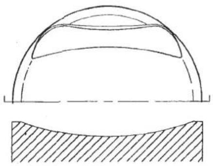
2:0 LITRE 907 8:4:1CR.

2-2 LITRE 912 944:1 CR.
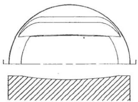
2-2 LITRE 912 10-9:1CR.

2·2 LITRE 910 751 CR.
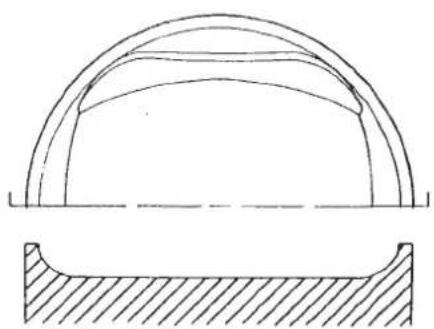
2·2 LITRE 910 8·0·1 CR
| - Rings | 2 compression, 1 oil control | |
| - Diameter | 907 - grade 'A' | 95.166/95.179 mm (3.7467/3.7472 in) |
| 907 - grade 'B' | 95.179/95.192 mm (3.7472/3.7477 in) | |
| 912 Std - grade 'A' | 95.148/95.161 mm (3.7460/3.7465 in) | |
| 912 Std - grade 'B' | 95.161/95.174 mm (3.7465/3.7470 in) | |
| 912 HC - grade 'A' | 95.205/95.219 mm (3.7482/3.7488 in) | |
| 912 HC - grade 'B' | 95.217/95.231 mm (3.7487/3.7493 in) | |
| - Grade diameter | - 907/912 Std | 15 mm (0.6 in) up from skirt edge ) 90° to |
| - 912 HC | 10.2mm (0.4 in) up from skirt edge ) pin axis | |
| - Gudgeon pin bore offset | 907/912 Std | 1.52 mm (0.060 in) towards thrust face |
| 912 HC | 1.50 mm (0.059 in) towards thrust face | |
| - Permissible weight variation between pistons | 907/912 Std | 3.5 grammes |
| 912 HC | 3.0 grammes | |
| - Ring gap | 907/912 Std - top | 0.38/0.51 mm (0.015/0.020 in) |
| - second | 0.48/0.61 mm (0.019/0.024 in) | |
| - scraper (rails) | 0.38/1.14 mm (0.015/0.045 in) | |
| 912 HC | - top & second | 0.40/0.65 mm (0.016/0.026 in) |
| - oil control | 0.30/0.60 mm (0.12/0.024 in) |

Piston (cont.)
-Piston ring to groove clearance
907/912 Std - Compression 0.038/0.089 mm (0.0015/0.0035 in)
-Oil control 0.038/0.064 mm (0.0015/0.0025 in)
912 HC - Compression 0.040/0.072 mm (0.0016/0.0028 in)
-Oil control 0.020/0.052 mm (0.0008/0.0020 in)
Cylinder Liner
- Type Wet, slip fit
- Material - 907/912 Std Cast Iron
-912 HC Nikosil coated, forged aluminium alloy
- Internal diameter
- 907/912 Std Measured 50mm from top across thrust axis
Grade 'A' 95.275/95.288 mm (3.7510/3.7515 in)
Grade 'B' 95.288/95.308 mm (3.7515/3.7520 in)
- 912 HC Measured 70mm from top across thrust axis
Grade 'A' 95.255/95.269 mm (3.7502/3.7507 in)
Grade 'B' 95.267/95.281 mm (3.7507/3.7512 in)
- Fitted height above block - 907/912 Std ('nip')
-912HC
0.10/0.15 mm (0.004/0.006 in) ×
up to engine number 12477
0.025/0.13 mm (0.001/0.005 in) 001/003
from engine number 12478
minus 0.025 to +0.050mm
(minus 0.001 to +0.002 in)
- Permissible variation between liners
0.03 mm (0.001 in) √
- Piston clearance in cylinder liner 907
0.10/0.13mm (0.004/0.005 in)
912 Std 0.11/0.15mm (0.005/0.006 in)
912 HC 0.05/0.08mm (0.002/0.003 in)
Lubrication System

Oil pressure under normal running condition (hot)
a). Not below 5 lb/sq.in. (0.35 kg./sq.cm.) at idle speed
b). Not below 35 lb/sq.in. (2.5 kg./sq.cm.) at 3,500 rpm
c): Not below 45 lb/sq.in. (3.2 kg./sq.cm.) at 6,500 rpm
Filter
Full-flow, disposable canister type with anti-flow back valve)
Pump - type
Eccentric rotor
- Drive
Toothed belt
- Rotor /annulus tip clearance
0.05 - 0.15 mm (0.002 - 0.006 in)
- Annulus end float
0.03 - 0.08 mm (0.001 - 0.003 in)
- Rotor end float
0.06 - 0.09 mm (0.0025 - 0.0035 in)
- Annulus to housing clearance
0.18 - 0.30 mm (0.007 - 0.012 in)
APR 1987
Dipstick tube standout from M.B.P.
119.5mm
Dellorto Carburettors
| Spec 1 | Spec 3 | Spec 5 | Elite)Eclat)man.Excel Std. Spec 9 | Elite)Eclat)autoEsp.S3 Std Spec 9 | Excel HC manualSpec 10 | Excel HC autoSpec 10 | Esprit S3 HCSpec 10 | |
| Carburettor Type (2 off)Lotus Part No. (Front)(Rear) | DHLA 45EB907E0789WB907E0790W | DHLA 45ED907E0789WD907E0790W | DHLA 45EE907E0789FE907E0790W | DHLA 45EA912E0789FA912E0790F5324A5323PBlue+Black | DHLA 45EA912E0940JA912E0941J5324A5324PBlue37 mm | DHLA 45DA912E9207FA912E9208F5382A5381PBlack37 mm | DHLA 45DA912E9226A912E92275387A5386P | DHLA45DA912E2336FA912E2337F5395A5394PBlack37 mm |
| Tag No. (Front)(Rear) | - | - | 5295A5294PGreen | 37 mm | 160 | 135 | 135 | 135 |
| Paint Spot on 'Dellorto'Choke | 38 mm | 35 mm | 36 mm | 160 | 230 | 150 | 150 | 150 |
| Main Jet | 142 | 130 | 160 | 7772-8 | 7772-8 | 7772-8 | 7772-8 | 7772-8 |
| Main Air Corrector Jet | 110 | 110 | 230 | 58 | 55 | 55 | 55 | 56 |
| Main Emulsion Tube | 7772-5 | 7772-5 | 7772-8 | 7850-9 | 7850-9 | 7850-9 | 7850-9 | 7850-9 |
| Idle Jet | 55L | 56 | 50 | 8.5g | 8.5g | 8.5g | 8.5g | 8.5g |
| Idle Jet Holder | 7850-1 | 7850-6 | 7850-7 | 14.5-15.0 | 14.5-15.0 | 14.5-15.0 | 14.5-15.0 | 14.5-15.0 |
| Float Weight | 10g | 10g | 10g | 170 | 170 | 170 | 170 | 170 |
| Float Setting Height (mm) | 16.5-17.0 | 16.5-17.0 | 16.5-17.0 | 38V 42H | 50H | 45H | 33 | 45H |
| Float Needle Valve | 170 | 170 | 170 | 95 | 95 | 95(R/B 80) | 80 | 80 |
| Pump Jet | 45 | 45 | 38V 42H | 7482-3 | 7482-3 | 7482-3 | 7482-3 | 7482-3 |
| Starter Jet | 70 | 70 | 70 | - | - | 70 | 70 | 70 |
| Starter Emulsion Tube | 7482-1 | 7482-1 | 7482-1 | 850-950 | 850-950 | 900-1000 | 900-1000 | 900-1000 |
| Power Jet | - | - | - | 0.7-1.5% | 0.7-1.5% | 0.5-1.5% | 0.5-1.5% | 0.5-1.5% |
| Slow Running Speed (rpm) | 900-1000 | 900-1000 | 900-1000 | 0.7-1.5% | 0.7-1.5% | 0.5-1.5% | 0.5-1.5% | 0.5-1.5% |
| Idle CO Level (hot) | 2.0-3.0% | 2.0-3.0% | 2.0-3.0% |
fdlaas/1
Zenith Carburettors
| Type and number | Zenith 175/CD SE (two) |
| Needle | B I D K |
| Spring Colour | Blue |
| Damper Oil | SAE 20W/50 |
| Lotus part number - Spec 2 | front B907E0791Wrear B907E0792W |
| - Spec 4,6,7,8 | front C907E0791F*rear C907E0792F* |
* Red paint spot on air valve housing. These carbs are to the same specification as the B prefix carbs, except for the inclusion of internal/external float vent valves.
Fast idle setting (engine warm)
| - Spec 2 | 2.16 - 2.41 mm. (0.085 - 0.095 in.) between starter cam and screw head in 'off' position |
| - Spec 4,6,7,8 | 1.27 mm. (0.050 in.) |
| Slow running speed | 950 - 1000 rpm |
Idle CO level (normal running temperature)
| - Spec 2 | (without air injection) 2.5 - 4.0 % CO |
| - Spec 4, 6 | This must be checked with the air injection disconnected and a reading taken via a sample pipe before the catalyst. To disconnect the air injection remove the air outlet hose (between outlet and non-return valve) from the air pump, and blank off the hose. Adaptor and sample pipe - Part No. T000T0321A. Blanking plug (for air hose) - Part No. T000T0322A Setting 3.5 - 4.5% CO |
| - Spec 7 | with air pump (and no catalyst) Tailpipe idle check - less than 1.0% C.O. with air on, 2.0 - 3.5% C.O. with air off. |
| Spec 7 | With pulse air injection system Upstream of catalyst 0.2 - 1.0% C.O. |
IGNITION SYSTEM
Type
- Spec 1,2,3,4,5,6
- Spec 7, 8, 9 (Esprit up to 1983. Not Excel)
- Spec 9 (Esprit 1983 on and Excel only)
Coil and Distributor
Coil and distributor with infra-red solid state 'Lumenition' system.
Coil and distributor with Lucas Constant Energy System
Number 1 cylinder
Ignition advance control
Toward front
Fully automatic
Sparking plugs:
With Lucas ignition leads - spec 1,3,5
-spec 2,4,6,7
With NGK ignition leads - spec 1,3,5,9
-spec 2,4,6,7,8
-spec 10
NGK BP6ES
NGK BP5ES
NGK BPR6ES
NGK BPR5ES
NGK BPR7ES
Spark plug gap - with contact breaker
0.6 mm. (0.023 in.)
- with high energy ignition 0.9 mm. (0.035 in.)
DISTRIBUTOR & IGNITION TIMING (All figures + 2°)
| Distributor Type | Vacuum Capsule (crank°) | Static Ignition Timing BTDC | Idle Speed Ignition Timing BTDC | Centrifugal Advance Characteristics (vacuum disconnected) crank rpm ± 2° | Ignition Timing to be set at | |
| Spec 1 | 25D(41584) | 8° Retard | 12° | 4° | Below 1,000 nil2,000 8° 3,000 16° | 28° BTDC @3,500 - 4,000 rpm(vacuum disconnected) |
| Spec 2 | 25D(41584) | 8° Retard | 8° | 0° | as Spec 1 | 24° BTDC @3,500 - 4,000 rpm(vacuum disconnected) |
| Spec 3 | 25D(41584) | blanked off | 16° | 16° | as Spec 1 | 32 - 34° BTDC @3,500 - 4,000 rpm(vacuum disconnected) |
| Spec 4,6 | 25D(41634A)or 45D(41626) | 8° Retard | 8° | 0° | Below 1,000 nil2,000 8° 4,000 18° 5,000 22° 6,000 26° | 22 - 24° BTDC @3,000 rpm(vacuum disconnected) |
| Spec 5 | 23D4 or 43D(41623) | - | 9° | - | as Spec 1 | 25° BTDC @3,500 - 4,000 rpm |
| Spec 7,8 | 45D (41626) with Lumenition | 8° Retard | 10° | 2° | as Spec 4,6 | 24 - 26° BTDC @3,000 rpm(vacuum disconnected) |
| Spec 9 | 43D with Lumenition or Constant Energy Ign. | - | 9° | - | as Spec 1 | 25° BTDC @3,500 - 4,000 rpm |
| Spec 10 | 45D (41946) Constant Energy Ign. | 22° Advance | 10° | 10° (hot) | as Spec 1 | 10° BTDC @ hot idle 950 ± 50 rpm |
FD1AAA/4
SECTION TD A
Distributor
Direction of rotation (from drive end)
Drive
Contact breaker gap (where fitted)
Contact breaker spring tension (measured at contact points)
Cam dwell angle
- 25D, 23D
- 45D, 43D
Firing angles
Capacitor value
Clockwise
Offset dog
0.35 - 0.40 mm. (0.014 - 0.016 in.)
0.51 - 0.68 kg.f. (18 - 24 oz.f.)
60° ± 3° changed during 1978 to 64° ± 3°
52° ± 4° changed during 1978 to 60° ± 3°
0°, 90°, 180°, 270°, ± 1°
Header tank cap relief valve pressure
Thermostat - (Temperate climates)
- (High ambient temperatures)
Impellor vanes to water pump housing clearance
Cooling system anti-freeze/inhibitor (year round)
Centrifugal pump and electric fan
0.7kg/cm 2 (10lb/in 2 ) or 1.1kg/cm 2 (15lb/in 2 )
82° C
74° C
907:0.50-0.75mm(0.020-0.030in)
912:0.25-0.40mm(0.010-0.016in)
'Shell Safe' or Union Carbide 'UT 184' minimum 25% maximum 60%
TORQUE LOADING FIGURES
| ENGINE | kgf.m | lbf.ft |
| Cylinder head (tighten cold) | ||
| both pairs (front and rear) nuts (oiled thread) | 9.7 | 70 |
| 3 pairs (in middle) nuts (oiled threads) | 10.4 | 75 |
| Sparking plugs | 3.3 - 3.9 | 24 - 28 |
| Camshaft covers | 0.40 - 0.55 | 3 - 4 |
| Camshaft housing | 1.9 - 2.2 | 14 - 16 |
| Camshaft sprockets | 3.5 | 25 |
| Main bearing housing - 907 - 12mm | 7.6 | 55 |
| (oiled threads) - 912 - 12mm | 9.0 | 65 |
| - 907/912 - 8mm | 1.9 - 2.2 | 14 - 16 |
| Crankshaft pulley | 8.0 - 8.3 | 58 - 60 |
| Connecting rod (big end) caps (oiled thread) | 11.6 - 11.9 | 84 - 86 |
| Fixed Flywheel - 907/912 | 6.5 - 6.8 | 47 - 49 |
| Flexplate flywheel (inc. auto flexplate) | 7.6 | 55 |
| Clutch assembly | 2.3 - 2.6 | 17 - 19 |
| Torque convertor to flexplate | 3.5 | 25 |
| Oil sump to main bearing housing - 907 | 1.0 - 1.1 | 7 - 8 |
| Oil sump to main bearing housing - 912 | 2.2 - 2.5 | 16 - 18 |
| Auxiliary housing to cylinder block | 1.8 - 2.1 | 13 - 15 |
| Auxiliary shaft sprocket | 3.5 | 25 |
| Oil pick-up pipe union | 7.6 | 55 |
| Retaining nut (belt tensioner) | 3.5 - 4.2 | 25 - 30 |
| All other 6mm nuts or setscrews | 1.0 - 1.1 | 7 - 8 |
| Stud - Cylinder head to cylinder block - 12mm | 4.1 | 30 |
| - Main bearing housing - 8mm | 1.7 | 12 |
| - Main bearing housing - 12mm | 5.5 | 40 |
| - Camshaft housing to cylinder head - 8mm | 1.7 | 12 |
| - Sump to main bearing housing - 6mm | 0.7 | 5 |
| - All other non-specified 8mm studs | 1.7 | 12 |
| Exhaust manifold to cylinder head | 1.9 - 2.2 | 14 - 16 |
| Inlet maniflod to cylinder head | 1.9 - 2.2 | 14 - 16 |
| Banjo bolt (fuel line to carburettors) | 2.2 | 16 |
| Purge pump thermal switch | 2.1 | 15 |
SECTION TD A
Zenith Carburettors
| Type and number | Zenith 175/CD SE (two) |
| Needle | B I D K |
| Spring Colour | Blue |
| Damper Oil | SAE 20W/50 |
| Lotus part number - Spec 2 | front B907E0791Wrear B907E0792W |
| - Spec 4,6,7,8 | front C907E0791F*rear C907E0792F* |
* Red paint spot on air valve housing. These carbs are to the same specification as the B prefix carbs, except for the inclusion of internal/external float vent valves.
Fast idle setting (engine warm)
| - Spec 2 | 2.16 - 2.41 mm. (0.085 - 0.095 in.) between starter cam and screw head in 'off' position |
| - Spec 4,6,7,8 | 1.27 mm. (0.050 in.) |
| Slow running speed | 950 - 1000 rpm |
Idle CO level (normal running temperature)
| - Spec 2 | (without air injection) 2.5 - 4.0 % CO |
| - Spec 4, 6 | This must be checked with the air injection disconnected and a reading taken via a sample pipe before the catalyst. To disconnect the air injection remove the air outlet hose (between outlet and non-return valve) from the air pump, and blank off the hose. Adaptor and sample pipe - Part No. T000T0321A. Blanking plug (for air hose) - Part No. T000T0322A Setting 3.5 - 4.5% CO |
| - Spec 7 | with air pump (and no catalyst) Tailpipe idle check - less than 1.0% C.O. with air on, 2.0 - 3.5% C.O. with air off. |
| Spec 7 | With pulse air injection system Upstream of catalyst 0.2 - 1.0% C.O. |
IGNITION SYSTEM
Type
- Spec 1,2,3,4,5,6
- Spec 7, 8, 9 (Esprit up to 1983. Not Excel)
- Spec 9 (Esprit 1983 on and Excel only)
Number 1 cylinder
Ignition advance control
Coil and Distributor
Coil and distributor with infra-red solid state 'Lumenition' system.
Coil and distributor with Lucas Constant Energy System
Toward front
Fully automatic
Sparking plugs:
With Lucas ignition leads - spec 1,3,5
- spec 2, 4, 6, 7
With NGK ignition leads - spec 1,3,5,9
- spec 2, 4, 6, 7, 8
- spec 1 0
NGK BP6ES
NGK BP5ES
NGKBPR 6 ES
NGKBPR 5 ES
NGKBPR 7 ES
Spark plug gap - with contact breaker
0.6 mm. (0.023 in.)
- with high energy ignition 0.9 mm. (0.035 in.)
DISTRIBUTOR & IGNITION TIMING (All figures + 2°)
| Distributor Type | Vacuum Capsule (crank°) | Static Ignition Timing BTDC | Idle Speed Ignition Timing BTDC | Centrifugal Advance Characteristics (vacuum disconnected) crank rpm ± 2° | Ignition Timing to be set at | |
| Spec 1 | 25D(41584) | 8° Retard | 12° | 4° | Below 1,000 nil2,000 8° 3,000 16° | 28° BTDC @3,500 - 4,000 rpm(vacuum disconnected) |
| Spec 2 | 25D(41584) | 8° Retard | 8° | 0° | as Spec 1 | 24° BTDC @3,500 - 4,000 rpm(vacuum disconnected) |
| Spec 3 | 25D(41584) | blanked off | 16° | 16° | as Spec 1 | 32 - 34° BTDC @3,500 - 4,000 rpm(vacuum disconnected) |
| Spec 4,6 | 25D(41634A)or 45D(41626) | 8° Retard | 8° | 0° | Below 1,000 nil2,000 8° 4,000 18° 5,000 22° 6,000 26° | 22 - 24° BTDC @3,000 rpm(vacuum disconnected) |
| Spec 5 | 23D4 or 43D(41623) | - | 9° | - | as Spec 1 | 25° BTDC @3,500 - 4,000 rpm |
| Spec 7,8 | 45D (41626) with Lumenition | 8° Retard | 10° | 2° | as Spec 4,6 | 24 - 26° BTDC @3,000 rpm(vacuum disconnected) |
| Spec 9 416146 | 43D with Lumenition or Constant Energy Ign. | - | 9° | - | as Spec 1 | 25° BTDC @3,500 - 4,000 rpm |
| Spec 10 416076 | 45D (41626) Constant Energy Ign. | 22° Advance | 10° | 10° (hot) | as Spec 1 | 10° BTDC @ hot idle 950 ± 50 rpm |
FDLAAA/4
Distributor
| Direction of rotation (from drive end) | Clockwise |
| Drive | Offset dog |
| Contact breaker gap (where fitted) | 0.35 - 0.40 mm. (0.014 - 0.016 in.) |
| Contact breaker spring tension (measured at contact points) | 0.51 - 0.68 kg.f. (18 - 24 oz.f.) |
| Cam dwell angle | |
| - 25D, 23D | 60° ± 3° changed during 1978 to 64° ± 3° |
| - 45D, 43D | 52° ± 4° changed during 1978 to 60° ± 3° |
| Firing angles | 0°, 90°, 180°, 270°, ± 1° |
| Capacitor value | 0.18 - 0.23 Microfarad |
Cooling System
| Type | Centrifugal pump and electric fan |
| Header tank cap relief valve pressure | 0.7kg/cm2(10lb/in2) or 1.1kg/cm2(15lb/in2) |
| Thermostat - (Temperate climates) | 82°C |
| - (High ambient temperatures) | 74°C |
| Impeller vanes to water pump housing clearance | 907 : 0.50 - 0.75 mm (0.020 - 0.030 in)912 : 0.25 - 0.40 mm (0.010 - 0.016 in) |
| Cooling system anti-freeze/inhibitor(year round) | 'Shell Safe' or Union Carbide 'UT 184'minimum 25% maximum 60% |
TORQUE LOADING FIGURES
| ENGINE | kgf.m | lbf.ft |
| Cylinder head (tighten cold) | ||
| both pairs (front and rear) nuts (oiled thread) | 9.7 | 70 |
| 3 pairs (in middle) nuts (oiled threads) | 10.4 | 75 |
| Sparking plugs | 3.3 - 3.9 | 24 - 28 |
| Camshaft covers | 0.40 - 0.55 | 3 - 4 |
| Camshaft housing | 1.9 - 2.2 | 14 - 16 |
| Camshaft sprockets | 3.5 | 25 |
| Main bearing housing - 907 - 12mm | 7.6 | 55 |
| (oiled threads) - 912 - 12mm | 9.0 | 65 |
| - 907/912 - 8mm | 1.9 - 2.2 | 14 - 16 |
| Crankshaft pulley | 8.0 - 8.3 | 58 - 60 |
| Connecting rod (big end) c (os (oiled thread) | 11.6 - 11.9 | 84 - 86 |
| Fixed Flywheel - 907/912 | 6.5 - 6.8 | 47 - 49 |
| Flexplate flywheel (inc. auto flexplate) | 7.6 | 55 |
| Clutch assembly | 2.3 - 2.6 | 17 - 19 |
| Torque convertor to flexplate | 3.5 | 25 |
| Oil sump to main bearing housing - 907 | 1.0 - 1.1 | 7 - 8 |
| Oil sump to main bearing housing - 912 | 2.2 - 2.5 | 16 - 18 |
| Auxiliary housing to cylinder block | 1.8 - 2.1 | 13 - 15 |
| Auxiliary shaft sprocket | 3.5 | 25 |
| Oil pick-up pipe union | 7.6 | 55 |
| Retaining nut (belt tensioner) | 3.5 - 4.2 | 25 - 30 |
| All other 6mm nuts or setscrews | 1.0 - 1.1 | 7 - 8 |
| Stud - Cylinder head to cylinder block - 12mm | 4.1 | 30 |
| - Main bearing housing - 8mm | 1.7 | 12 |
| - Main bearing housing - 12mm | 5.5 | 40 |
| - Camshaft housing to cylinder head - 8mm | 1.7 | 12 |
| - Sump to main bearing housing - 6mm | 0.7 | 5 |
| - All other non-specified 8mm studs | 1.7 | 12 |
| Exhaust manifold to cylinder head | 1.9 - 2.2 | 14 - 16 |
| Inlet manifold to cylinder head | 1.9 - 2.2 | 14 - 16 |
| Banjo bolt (fuel line to carburettors) | 2.2 | 16 |
| Purge pump thermal switch | 2.1 | 15 |

SECTION TD B
TECHNICAL DATA
SECTION TD B - ENGINE TYPE 910

| Page | |
| Engine Number | 2 |
| Engine Specification | 3 |
| Cylinder Head | 3 |
| Camshafts & Valve Timing | 4 |
| Valve Gear | 4 to 6 |
| Auxiliary Shaft | 6 |
| Crankshaft | 6 |
| Main Bearing Configuration | 6 |
| Flywheel | 7 |
| Connecting Rod | 7 |
| Gudgeon Pin | 7 |
| Piston & Liner | 7/8 |
| Lubrication System | 8 |
| Dellorto Carburettor | 9 |
| Ignition System | 9/10 |
| Torque Settings | 11 |

Before commencing work on any Lotus engine, first check the engine number and prefix letters to establish the engine specification. This number is stamped on the right hand rear of the cylinder block, above the starter motor, and is duplicated on the vehicle identification plate fixed to either the right or left hand inner wheelarch under the front bonnet.
Example

Market
A = Japan C = Europe F = Sweden / Australia / Switzerland H = Canada / 49 States N. America J = California L = 5 0 - States N. America
Engine Equipment
C = Standard D = Air Conditioning A = High Compression P = High Compression / Air Conditioning
Wet Sump Introduction
From 1980 until late 1981/early 1982, all Turbo Esprit engines (type 910) were built with a 'dry sump' lubrication system. Cars not fitted with air conditioning were changed to a 'wet sump' configuration in late 1981, followed by air conditioned cars in early 1982.
Wet sump introductory VIN's are as follows:
Domestic heater 82D1193
Domestic air conditioning 82D1261
ROW (air conditioning) 82 A/E/G/H/S 0399
All Federal cars are wet sump.
SECTION TD B
ENGINE
| Type designation | 910 | |
| Max. rpm of engine | 7,000 | |
| No. of cylinders | 4 | |
| Firing order | 1,3,4,2 | |
| Capacity | 2174cc (132.6 cu.in.) | |
| Stroke | 76.2mm (3.00 in.) | |
| Bore (nominal) | 95.29mm (3.75 in.) | |
| Compression ratio | - Std. | 7.5 : 1 |
| - H.C. | 8.0 : 1 | |
| Compression pressure | - Std. | 8.8 bar ( 130 lb/in2 ) minimum |
| - H.C. | 9.5 bar ( 140 lb/in2 ) minimum | |
| Maximum boost pressure | - Std. | 0.55 bar ( 8.0 lb/in2 ) |
| - H.C. | 0.65 bar ( 9.5 lb/in2 ) | |
| Engine number location | On top rear of cylinder block near starter mounting |
Engine belt tensions - Toothed timing belt, using Burroughs gauge part number T000G0025J, 90 - 95 units cold (60°F/20°C) See Section EA.9.
| (-Alternator 'V' belt) | 12 mm (0.5 in.) ( 1/2 in.) | |
| Total movement using moderate finger pressure on longest belt run. | (-Compressor 'V' belt)A/C)(--Vacuum Pump 'V' belt)(--Air Pump 'V' belt) | 9 mm (0.35 in.) (3/8 in.) |
CYLINDER HEAD
| Material | Aluminium alloy |
| Gasket | Steel/asbestos |
Combustion chamber depth (nos. 1 & 4) 12.19 - 12.57 mm (0.485 - 0.500 in.)
CAMSHAFTS AND VALVE TIMING
| Cam Type Designation | Identif. on shank between pulley & cam hsg. | Duration (crank degrees) | Inlet M.O.P. ATDC* | Cam Pulley Timing Dot | Exhaust M.O.P BTDC* | Cam Pulley Timing Dot | ||
| Spec.No. | Lift | |||||||
| Domestic & Export | 107 | 777.... | 252° | 0.378" | 104° | green | 104° | green |
| USA (Carb) | 107 | 777.... | 252° | 0.378" | 110° | red | 104° | green |
| USA (HCI) | 107 | 777.... | 252° | 0.378" | 110° | red | 100° | blue |
FD1AAC/1
* All cams are symmetrical opening/closing
VALVES
| Angle of valve seats and faces | 45° |
| Head diameter - Inlet | 35.47 - 35.65 mm (1.396 - 1.404 in.) |
| - Exhaust | 30.70 - 30.90 mm (1.209 - 1.217 in.) |
| Stem diameter - Inlet | 7.125 - 7.137 mm (0.2805 - 0.2810 in.) |
| - Exhaust | 7.955 - 7.970 mm (0.3132 - 0.3138 in.) |
| Stem clearance in guide - Inlet | 0.008 - 0.046 mm (0.0003 - 0.0018 in.) |
| - Exhaust | 0.030 - 0.070 mm (0.0012 - 0.0027 in.) |
| Valve clearance (cold) - Inlet | 0.13 - 0.18 mm (0.005 - 0.007 in.) |
| - Exhaust | 0.25 - 0.31 mm (0.010 - 0.012 in.) |
Valve Seat Inserts
| Bore in head: | ||
| Standard | - Inlet | 37.235/37.260 mm. (1.466/1.467 in.) |
| - Exhaust | 34.290/34.315 mm. (1.350/1.351 in.) | |
| +0.025 mm (0.001 in) | - Inlet | 37.260/37.285 mm. (1.467/1.468 in.) |
| - Exhaust | 34.315/34.340 mm. (1.351/1.352 in.) | |
| +0.050 mm (0.002 in) | - Inlet | 37.285/37.315 mm. (1.468/1.469 in.) |
| - Exhaust | 34.340/34.365 mm. (1.352/1.353 in.) | |
| +0.127 mm (0.005 in) | - Inlet | 37.365/37.390 mm. (1.471/1.472 in.) |
| - Exhaust | 34.415/34.440 mm. (1.355/1.356 in.) | |
Outside diameter of seat
| Standard | - Inlet | 37.325/37.350 mm. (1.4695/1.4705 in.) |
| - Exhaust | 34.380/34.405 mm. (1.3535/1.3545 in.) | |
| + 0.025 mm (0.001 in) | - Inlet | 37.350/37.375 mm. (1.4705/1.4715 in.) |
| - Exhaust | 34.405/34.430 mm. (1.1345/1.3555 in.) | |
| + 0.050 mm (0.002 in) | - Inlet | 37.375/37.400 mm. (1.4715/1.4725 in.) |
| - Exhaust | 34.430/34.455 mm. (1.3555/1.3565 in.) | |
| + 0.127 mm (0.005 in) | - Inlet | 37.450/37.475 mm..(1.4745/1.4755 in.) |
| - Exhaust | 34.505/34.530 mm. (1.3585/1.3595 in.) |
Valve Springs
Type
Dual
| Free Length | Rate | ||
| Inner | Outer | Inner | Outer |
| 42.2 mm(1.66 in.) | 48.5 mm(1.91 in.) | 11.0 kg/cm(61.5 lb/in) | 22.5 kg/cm(126 lb/in) |
FD1AAD/1
Valve Guides
Length - Inlet and Exhaust 53.34 mm. (2.100 in.)
Internal diameter (to ream after fitting) - Inlet 7.145 - 7.170 mm. (0.2813 - 0.2823 in.)
- Exhaust 8.000 - 8.025 mm. (0.3150 - 0.3159 in.)
Bore in head - Inlet and Exhaust
| Standard | 11.915 - 11.925 mm. (0.4690 - 0.4695 in.) |
| +0.025 mm. (0.001 in.) | 11.940 - 11.950 mm. (0.4700 - 0.4705 in.) |
| +0.050 mm. (0.002 in.) | 11.965 - 11.975 mm. (0.4710 - 0.4715 in.) |
| +0.127 mm. (0.005 in.) | 12.040 - 12.050mm. (0.4740 - 0.4745 in.) |
Outside diameter of guide
| Standard | 11.940 - 11.950 mm. (0.4700 - 0.4705 in.) |
| +0.025 mm. (0.001 in.) | 11.965 - 11.975 mm. (0.4710 - 0.4715 in.) |
| +0.050 mm. (0.002 in.) | 11.990 - 12.000 mm. (0.4720 - 0.4725 in.) |
| +0.127 mm. (0.005 in.) | 12.065 - 12.080 mm. (0.4750 - 0.4755 in.) |
Camshafts
| End float - Dimension | 0.03 - 0.20 mm. (0.001' - 0.008 in.) |
| - Controlled by | Selective thrust washers |
| Running clearance (except front) | 0.050 - 0.090 mm (0.0020 - 0.0035 in.) |
| (front only) | 0.075 - 0.115 mm (0.0030 - 0.0040 in.) |
Cam Followers
| Bore in camshaft housings | 34.925 - 34.940 mm. (1.3750 - 1.3756 in.) |
| Outside diameter | 34.904 - 34.912 mm. (1.3742 - 1.3745 in.) |
AUXILIARY SHAFT
| Running Clearance | 0.025 - 0.065 mm. (0.0009 - 0.0025 in.) |
| End Float | 0.013 - 0.038 mm. (0.0005 - 0.0015 in.) |
CRANKSHAFT
| Balance (inc. flywheel and clutch) | Within 15 gr.cm. (0.2 oz.in.) |
| Diameter - Main journal (No.1.to 4 inc.) | 63.487 - 63.513 mm. (2.4995 - 2.5005 in.) |
| - Main journal (No. 5 only) | 63.500 - 63.513 mm. (2.5000 - 2.5005 in.) |
| - Crankpin | 50.736 - 50.762 mm. (1.9975 - 1.9985 in.) |
| End float - Dimension | 0.08 - 0.20 mm. (0.003 - 0.008 in.) |
| - Controlled by | Selective thrust washers on rear main bearing |
| Bearings (main) - Number | 5 |
| - Type | Steel backed, leaded bronze |
| - Static clearance* | 0.013 - 0.056 mm. (0.0005 - 0.0022 in.) |
| Mac. undersize for regrind | 0.508 mm. (0.0200 in.) |
* Bearing clearance is measured with Plastigage.
MAIN BEARING CONFIGURATION
| ENGINE TYPE | FRONT 1 | 2 | CENTRE 3 | 4 | REAR 5 | |
| 910 Turbo Dry/Wet Sump | Upper | Groove/Hole | Groove/Hole | Plain/Hole | Groove/Hole | Groove/Hole |
| Lower | Plain | Plain | Plain | Plain | Plain |
SECTION TD B
FLYWHEEL
Max. axial run-out over clutch face 0.05 mm. (0.002 in.)
CONNECTING ROD
Type 'I' section
Material Steel forging
Distance between centres 139.70 mm. (5.500 in.)
± 0.25 mm. (0.001 in.)
Bearings (big end) - Type Steel backed, leaded bronze
- Static clearance * 0.025 - 0.081 mm. (0.0010 - 0.0032 in.)
- End float on crankpin 0.10 - 0.25 mm. (0.004 - 0.010 in.)
Small end bore (bushed) 25.405/25.410 mm. (1.0002 - 1.0004 in.)
Permissible weight variation between rods 2 grammes (in any set)
* Bearing clearance is measured with Plastigage
GUDGEON PIN
Type Fully floating
Location Circlips
Diameter 25.40 mm. (1.00 in.)
Class of fit Finger push fit at 20° C ( 68° F)
PISTON AND LINER
Piston - Type Solid skirt
- Material Aluminium alloy
- Rings 2 compression, 1 oil control
- Diameter 910 Std - grade 'A' 95.148/95.161 mm (3.7460/3.7465 in)
910 Std - grade 'B' 95.161/95.174 mm (3.7465/3.7470 in)
910 HC - grade 'A' 95.205/95.219 mm (3.7482/3.7488 In)
910 HC - grade 'B' 95.217/95.231 mm (3.7487/3.7493 in)
- Grade diameter - 910 Std 15 mm (0.6 in) up from skirt edge } 90° to - 910 HC 10.2mm (0.4 in) up from skirt edge pin axis
- Gudgeon pin bore offset - 910 Std 1.52 mm (0.060 in) towards thrust face - 910 HC Zero
- Permissible weight variation between pistons
3 grammes
- Ring gap 910 Std. - top 0.38/0.51 mm (0.015/0.020 in)
- second 0.48/0.61 mm (0.019/0.024 in)
- scraper (rails) 0.38/1.14 mm (0.015/0.045 in)
910 HC - top & second 0.40/0.65 mm (0.016/0.026 in)
-oil control 0.30/0.60 mm (0.012/0.024 in)
-Piston ring to groove clearance
910 Std. - Compression 0.038/0.089 mm (0.0015/0.0035 in)
-Oil control 0.038/0.064 mm (0.0015/0.0025 in)
910 HC - Compression 0.040/0.072 mm (0.0016/0.0028 in)
-Oil control 0.020/0.052 mm (0.0008/0.0020 in)
Cylinder Liner - Type Wet, slip fit
- Material - 910 Std. Cast Iron
- 910 HC Nikosil coated, forged aluminium alloy
- Internal diameter
- 910 Std. Measured 50mm from top across thrust axis Grade 'A' 95.275/95.288 mm (3.7510/3.7515 in)
Grade 'B' 95.288/95.308 mm (3.7515/3.7520 in)
- 910 HC Measured 70mm from top across thrust axis
Grade 'A' 95.255/95.269 mm (3.7502/3.7507 in)
Grade 'B' 95.267/95.281 mm (3.7507/3.7512 in)
- Fitted height above block - 910 Std. 0.025/0.13 mm (0.001/0.005 in) ('nip')
- 910 HC minus 0.025 to + 0.050mm
(minus 0.001 to +0.002 in)
- Permissible variation between liners 0.03 mm (0.001 in)
- Piston clearance in cylinder liner 910 Std. 0.11/0.15 mm (0.005/0.006 in)
910 HC 0.048/0.076 mm (0.002/0.003 in)
LUBRICATION SYSTEM
Minimum oil pressure under normal working conditions (hot);
| Wet Sump | Dry Sump | |||
| - at idle speed | 5 lb/in 2 | (0.35 kg/cm 2 ) | 5 lb/in 2 | (0.35 kg/cm 2 ) |
| - at 3,500 rpm | 35 | (2.5) | 40 | (2.8) |
| - at 6,500 rpm | 45 | (3.2) | 50 | (3.6) |
Filter Full flow disposable canister type with anti-flow back valve
Dry Sump
Pump - type
Eccentric rotor. 2 scavenge & 1 pressure pump in common unit driven by toothed belt
Wet Sump
Pump type Eccentric rotor. Driven by cam belt
- rotor/annulus tip clearance 0.05/0.15 mm (0.002/0.006 in)
- annulus end float 0.03/0.08 mm (0.001/0.003 in)
- rotor end float 0.06/0.09 mm (0.0025/0.0035 in)
- annulus to housing clearance 0.18/0.30 mm (0.007/0.012 in)
DELLORTO CARBURETTORS
| Export 'Std' | Export 'HC' | ||
| Carburettor Type (2 off)Tag No. - Front- RearLotus Part No. - Front- RearChokeMain JetMain Air Corrector JetMain Emulsion TubeIdle JetIdle Jet HolderFloat WeightFloat Setting HeightNeedle ValvePump JetStarter JetStarter Emulsion TubeSlow Running SpeedIdle CO Level (hot)Pump DeliveryPower JetFuel Delivery Pressure(at idle speed) | DHLA 40H5322A5321PB910E0926FB910E0925F36 mm1852007772-12407850-78.5g14.5-15.0mm20048H (special)807482-3850 rpm1.0 ± 0.5 %7cc/20 stks.-4.0 ± 0.5 psi | DHLA 45M5390A5389PA910E6855FA910E6856F35 mm1601807772-14587850-98.5g14.5-15.0mm20035807482-3850-950 rpm1.0 ± 0.5 %8cc/20 stks.Blank4.0 ± 0.5 psi | DHLA 45MA910E6633A910E663237 mm1652307772-13527850-98.5g14.5-15.0mm20038H807482-3950 rpm0.8 %8cc/20 stks.1104.0 - 4.5 psi |
FD1AAE/1
IGNITION SYSTEM
| Type - Domestic/ROW 1980 - early 1983 | Coil and distributor with infra-red solid state 'Lumenition' system |
| - 1983 on + Federal | Coil and distributor with Lucas 'Constant Energy' ignition system |
| Number 1 cylinder | Toward front |
| Sparking Plugs - Domestic/RoW (Std.) | NGK BPR 6ES |
| - Federal & 'HC' | NGK BPR 6EY |
| Spark Plug Gap | 0.9 mm (0.035 in.) |
Distributor
| Direction of rotation (from drive end) | Clockwise |
| Drive | Offset dog |
DISTRIBUTOR & IGNITION TIMING (all figures ± 2°)
| Market | Distributor Type | Vacuum Capsule crank° | Static Ign. Timing | Idle Speed Ign. Timing | Centrifugal Advance Characteristics | Ignition Timing to be set at | |
| crank rpm | crank° | ||||||
| Dom/Export Prior '87 MY | 43D Lumenition or Lucas Constant Energy | - | 12° BTDC | 12° BTDC | Below 1,000 2,000 3,000 | nil 8° 16° | 28° @ 3,500/ 4,000rpm |
| USA Prior '86 MY (Carb) | 45DM4 Lucas Constant Energy | 18° Advance | 1° BTDC | 1° BTDC | Below 1,000 1,500 2,100 2,800 5,000 | nil 3° 12° 15° 16° | Idle (950rpm) |
| USA '86 MY onward (HCI) | 45DM4 Lucas Constant Energy | 28° Advance | 15° BTDC | 15° BTDC | 2,500 5,000 | minus 3° minus 6° | Idle (900 - 1000rpm) |
| Dom/ Export '87 MY onward | 45DM4 Lucas Constant Energy | 28° Advance | 10° BTDC | 10° BTDC | Below 1,000 2,000 5,000 | nil 11° 8° | Hot Idle (850 - 950 rpm) |
(fdlaam/1)
TORQUE LOADING FIGURES
| ENGINE | kgf.m | lbf.ft |
| Cylinder head (tighten cold) | ||
| both pairs (front and rear) nuts | 9.7 | 70 |
| 3 pairs (in middle) nuts | 10.4 | 75 |
| Sparking plugs | 2.5 | 18 |
| Camshaft covers | 0.40-0.55 | 3-4 |
| Camshaft housings | 1.9-2.2 | 14-16 |
| Camshaft sprockets | 3.5 | 25 |
| Main bearing housing - 12 mm (Dry Sump) | 10.4 | 75 |
| Main bearing housing - 12 mm (Wet Sump) | 9.0 | 65 |
| - 8 mm | 1.9-2.2 | 14-16 |
| Crankshaft pulley | 8.0-8.3 | 58-60 |
| Connecting rod (big end) caps | 11.6-11.9 | 84-86 |
| Flywheel | 7.6 | 55 |
| Clutch Assembly | 2.3-2.6 | 17-19 |
| Oil sump to main bearing housing (all) | 2.2-2.5 | 16-18 |
| Auxiliary housing to cylinder block | 1.8-2.1 | 13-15 |
| Auxiliary shaft sprocket | 3.5 | 25 |
| Oil pick-up pipe union | 7.6 | 55 |
| Retaining nut (belt tensioner) | 3.5-4.2 | 25-30 |
| All other 6 mm nuts or setscrews | 1.0-1.1 | 7-8 |
| Stud - Cylinder head to cylinder block - 12 mm | 5.5 | 40 |
| - Main bearing housing - 8 mm | 1.7 | 12 |
| - Main bearing housing - 12 mm | 5.5 | 40 |
| - Camshaft housing to cylinder head - 8 mm | 1.7 | 12 |
| - Sump to main bearing housing | 0.7 | 5 |
| - Wastegate to adaptor (10mm) | 4.8 | 35 |
| All other non-specified 8mm studs | 1.7 | 12 |
| Exhaust manifold to cylinder head | 1.9-2.2 | 14-16 |
| Wastegate to adaptor | 4.8 | 35 |
| Inlet manifold to cylinder head | 1.9-2.2 | 14-16 |
| Engine mounting legs to rubbers | 5.5-6.2 | 40-45 |
| Mounting rubbers to chassis | 3.5 | 25 |
TECHNICAL DATA
SECTION TD D - VEHICLE, ESPRIT S3 & TURBO
Page
Dimensions 2
Capacities 2
Suspension 3
Steering 3
Clutch 4
Transmission 4
Cooling System 4
Brakes 5
Wheels & Tyres 5/6
Electrical Equipment 7
Torque Settings 7/8
DIMENSIONS
| Overall Length | (Series 3) | 4225 mm (166.3 in.) |
| (Turbo) | 4290 mm (169 in.) | |
| Overall Width | 1860 mm (73.3 in.) | |
| Overall Height | (Series 3) | 1111 mm (43.7 in.) |
| (Turbo - European) | 1118 mm (44.0 in.) | |
| (Turbo - Federal) | 1130 mm (44.5 in.) | |
| Wheelbase | 2438 mm (96.0 in.) | |
| Front Track | (14 in. Wheels) | 1544 mm (60.8 in.) |
| (15 in. Compomotive Wheels) | 1536 mm (60.5 in.) | |
| (15 in. BBS Wheels) | 1524 mm (60.0 in.) | |
| Rear Track | 1554 mm (61.2 in.) | |
| Ground Clearance, | Federal Spec. | 146 mm (5.8 in.) approx. Below rad. duct with driver only |
| Turning Circle | (between kerbs) | 10.6 m (34 ft 9 in) |
| Kerb Weight(with a/c) | (Series 3 prior to '85 MY) | 1100 kg (2425 lb) |
| (Series 3 '85 MY on) | 1130 kg (2492 lb) | |
| (Turbo Dom/Exp prior '85 MY) | 1200 kg (2645 lb) | |
| (Turbo Dom/Exp '85 MY on) | 1225 kg (2701 lb) | |
| (Turbo USA) | 1226 kg (2703 lb) | |
| Gross Weight | (Series 3) | 1340 kg (2955 lb) |
| (Turbo Dom/Exp prior to '85 MY) | 1389 kg (3063 lb) | |
| (Turbo Dom/Exp '85 MY on) | 1452 kg (3202 lb) | |
| (Turbo USA) | 1453 kg (3200 lb) |
CAPACITIES
Except Dry Sump Turbo
| Engine (inc. filter) - Dry- Refill | 6.5 litre (11.4 imp. pt. 13.7 U.S. pt.)5.4 litre (9.4 imp. pt. 11.4 U.S. pt.)0.85 litre (1.5 imp. pt. 1.8 U.S. pt.) |
| Difference between high and low dipstick marks |
Dry Sump Turbo
| Engine (inc. filter) - Dry- Refill | 6.5 litre (11.4 imp. pt. 13.7 U.S. pt.)5.0 litre (8.8 imp. pt. 10.6 U.S. pt.)1.0 litre (1.8 imp. pt. 2.1 U.S. pt.) |
| Difference between high and low dipstick marks |
| Transmission | 2.25 litre (4.8 U.S. pt.) |
| Cooling System - Series 3 | 10.8 litre (19 imp. pt. 22.8 U.S. pt.) |
| - Turbo | 12 litre (21 imp. pt. 25 U.S. pt.) |
| Fuel System | - Series 3 | 67 litre | (14.8 imp. gall. 17.7 U.S. gall.) |
| - Turbo | 86 litre | (18.9 imp. gall. 22.7 U.S. gall.) |
SUSPENSION
Front (Prior to '85 M.Y.);
Upper wishbone and lower transverse link with anti-roll. Co-axial coil spring and telescopic damper.
Chassis height below chassis front crossmember 170 mm for checking suspension geometry.
| Camber | 0° 30' negative ± 0° 15' |
| Castor | 3° ± 0° 30' (within 0° 30' side to side) |
| Toe-in | 2mm overall ± 1mm |
| Steering Axis Inclination (K.P.I.) | 9° nominal |
| Front Hub Endfloat | 0.08 - 0.13 mm (0.003 - 0.005 in.) |
Front ('85 M.Y. on);
Upper and lower wishbones. Co-axial coil spring and telescopic damper. Anti-roll bar.
Chassis height below chassis front crossmember 170 mm for checking suspension geometry
| Camber | 0° 30' negative ± 0° 30' |
| Castor | min 1° 45' max 3° (within 0° 30' side to side) |
| Toe in | 1.6mm each side, + 0 - 1 mm |
| Steering Axis Inclination (K.P.I.) | 9° 23' nominal |
| Front Hub Endfloat | 0.05mm (0.002 in) maximum |
Rear: Upper and lower transverse link with box section trailing radius arm. Co-axial coil spring and damper
Chassis height below rear lower link chassis 170 mm brackets for checking geometry
| Camber | 0° 30' negative ± 0° 15' |
| Toe in | 1.5mm each side ± 0.5 mm |
STEERING
Type Manual rack and pinion with energy absorbing collapsible steering column
Turns, lock to lock 2.9
CLUTCH
| Type | Single dry plate, Diaphragm spring Hydraulic |
| Release mechanism | |
| Master cylinder bore diameter (not LHD S3) | 15.88 mm (0.625 in.) |
| LHD S3 | 17.78 mm (0.700 in.) |
| Slave cylinder bore diameter | 22.23 mm (0.875 in.) |
| Friction plate - diameter - S3 | 216 mm (8.5 in.) |
| - Turbo | 241 mm (9.5 in.) |
| - Number of springs | 6 |
| Free Play at release lever - S3 (prior to '85) | 3 mm (0.12 in.) |
| - S3 ('85 on) & Turbo | Self adjusting slave cylinder |
TRANSMISSION
Type Manual. 5 forward gears (all syncromesh) and reverse
| Gear | Internal Ratio | Speed in mph (kph) per 1000 rpm | |
| 14 in wheels | 15 in wheels | ||
| Fifth | 0.76:1 | 21.85 (35.16) | 22.58 (36.35) |
| Fourth | 0.97:1 | 17.15 (27.59) | 17.69 (28.48) |
| Third | 1.32:1 | 12.58 (20.24) | 13.00 (20.93) |
| Second | 1.94:1 | 8.56 (13.77) | 8.84 (14.23) |
| First | 2.92:1 | 5.69 (9.15) | 5.88 (9.47) |
| Reverse | 3.46:1 | - - | - - |
| Final Drive | 4.375:1 | - - | - - |
| Speedometer gears - Driving gear | 5 teeth |
| - Driven gear | 17 teeth |
COOLING SYSTEM
| Type | Centrifugal water pump. Electric cooling fans with thermal switch. |
| Header Tank Cap Relief Valve Pressure | 0.7 kg/cm22 (10 lb/in22) or 1.1 kg/cm2 (15 lb/in2) |
| Thermostat nominal opening temperature | 74°C S3 hot climates 82°C S3 temperate climates and Turbo |
| Impellor Vanes to water pumphouring clearance | 0.25 - 0.40 mm (0.010 - 0.016 in.) |
| Cooling system anti-freeze/corrosion inhibitor | Minimum 25% strength.Up to 60% in cold climates. |
BRAKES
Type
Disc front, inboard disc rear, servo assisted dual hydraulic circuit.
Brake Discs
| Up to '84 model year | '85 model year | ||
| Solid Front | Solid Rear | Ventilated Front | Solid Rear |
| 265mm(10.4 in) | 275mm(10.8 in) | 258mm(10.2 in) | 275mm(10.8 in) |
| 12.7mm(0.50 in) | 10.0mm(0.39 in) | 20.0mm(0.79 in) | 12.0mm(0.47 in) |
| 11.4mm(0.45 in) | 9.0mm(0.35 in) | 19.0mm(0.75 in) | 11.0mm(0.43 in) |
| 0.09mm0.0035 in) | 0.09mm(0.0035 in) | 0.15mm(0.006) | 0.2mm(0.008 in) |
Diameter
Thickness, nominal
Thickness, minimum
Run-out, maximum
Handbrake -
Mechanical operation of rear pads. Self adjusting
WHEELS & TYRES
Series 3 with 14" wheels
Wheels - Type
- Size - front
- rear
Tyres - Type
- Size - front
- rear
- spare (if fitted)
- Pressure - front
- rear
- spare
Light alloy Speedline
7 JK × 14
7.5 JK × 14
Goodyear 'NCT' or 'Eagle NCT'
205/60 VR14
205/70 VR14
185/70 HR13
1.40 kg/cm 2 (1.35 bar, 20 lb/in 2 )
1.90 kg/cm 2 (1.85 bar, 27 lb/in 2 )
2.10 kg/cm 2 (2.05 bar, 30 lb/in 2 )
Series 3 with 15" wheels, and Turbo
Wheels - Type - early Turbo
- all others
- Size - front
- rear
Tyres - Type
- Size - front
- rear
- spare (if fitted)
3-piece, light alloy Compomotive
Light alloy BBS
7 J × 15
8 J×15
Goodyear 'NCT' or 'Eagle NCT'
195/60 VR 15
235/60 VR 15
175/70 SR14
15" Tyre Replacement
Cars 1985 Model Year onwards: Goodyear 'NCT' tyres of a new specification were introduced on 1985 Model Year Esprit S3 and Turbo models, together with a revised front suspension. For 1985 M.Y. and later models it is essential that ONLY either the new specification Goodyear 'NCT' tyres or Goodyear 'Eagle NCT' tyres are fitted. These two tyres differ in name only and may be safely mixed, but tyres made to the pre '85 specification should not be used. For identification of tyre specification see below.
| Tyre Pressures | - front | 1.45 bar | (21 lb/in 2 ) |
| - rear | 1.70 bar | (25 lb/in 2 ) | |
| - spare | 2.05 bar | (30 lb/in 2 ) |
Cars Prior to 1985 Model Year: If tyres to the pre '85 specification are not available, the later type Goodyear 'NCT' or 'Eagle NCT' may be used but only in axle sets, and with the tyre pressures of only the later spec. tyres increased as below.
Tyre Pressures-
| Pre '85 M.Y. car with | |||
| Pre '85 spec. tyre | |||
| front | 1.45 bar | (21 lb/in 2 ) | |
| rear | 1.70 bar | (25 lb/in 2 ) | |
| spare | 2.05 bar | (30 lb/in 2 ) | |
| Pre '85 car with | ||
| '85 onwards spec. tyre | ||
| front | 1.60 bar | (23 lb/in 2 ) |
| rear | 1.90 bar | (27 lb/in 2 ) |
| spare | 2.05 bar | (30 lb/in 2 ) |
Identification of tyre spec.
Embossed in the sidewall of each tyre, on one side only, are the letters D.O.T. followed by a series of numbers and letters. This format is the date coding employed by tyre manufacturers to identify the time and place of build of each tyre. Goodyear also include a coding which identifies the make up of each tyre.
Reference need only be made to the last three digits.


Any tyre manufactured on or after week number 38 of year 4 is to 1985 specification.
Unused 1985 spec. tyres also have in the tread area 2 identifying circumferential yellow colour bands.
ELECTRICAL EQUIPMENT
| Alternator | - Series 3 & Dom/Exp Turbo | Motorola 70 amp |
| - USA Turbo | Motorola 90 amp | |
| Starter Motor | - type | Lucas 2M100 |
| - drive | pre-engaged | |
| - brush spring tension | 1.02 kgf (36 ozf) | |
| - light running current | 40 amp @ 6,000 rpm | |
| - lock torque | 1.99 kgf.m (14.4 lbf.ft) | |
| @ 463 amps | ||
| Battery - type | - Dom/Exp prior '85 MY | Chloride type 385 |
| - Dom/Exp '85 & '86 MY | Tungstone type 065 | |
| - USA prior '86 MY | ||
| - Dom/Exp '87 MY on | Tungstone type 088 | |
| - USA '86 MY on | ||
| - performance | - Chloride type 385 | 55 amp hr |
| - Tungstone type 065 | 255 amp cold start* | |
| - Tungstone type 088 | 330 amp cold start* | |
| * 1 min @ -18°C to 1.4 VPC |
TORQUE SETTINGS
Front Suspension (Prior to '85 M.Y.)
| kgf.m | lbf. ft. | |
| Stub axle to vertical link | 11.0-15.0 | 80-110 |
| *Upper wishbone to chassis | 5.5-6.2 | 40-45 |
| Upper ball joint to wishbone | 1.4-1.8 | 10-13 |
| Ball joint to vertical link | 5.3-5.8 | 38-42 |
| Steering arm to vertical link | 3.6-4.7 | 26-34 |
| Caliper mounting plate to vertical link | 2.5-3.0 | 18-22 |
| *Lower link to chassis | 5.5-6.2 | 40-45 |
| Lower link to trunnion | 4.4-4.7 | 32-34 |
| Anti-roll bar to lower link | 0.8-1.4 | 6-10 |
| Anti roll bar to chassis | 6.9-8.3 | 50-60 |
| *Damper to lower link | 6.9-8.3 | 50-60 |
| xDamper top stem to chassis | see below | |
| Wheel nuts or bolts | 9.0 | 65 |
Front Suspension (1985 M.Y. onwards)
| *Upper wishbone to chassis | 6.9 | 50 |
| Upper ball joint to wishbone | 2.1 | 15 |
| Upper ball joint to vertical link | 5.5 | 40 |
| Steering arm to vertical link | 9.0 | 65 |
| *Lower wishbone to chassis | 6.9 | 50 |
| Lower ball joint to vertical link | 9.0 | 65 |
| Anti-roll bar to chassis | 9.0 | 65 |
| *Damper to lower wishbone | 6.9 | 50 |
| xDamper top stem to spring plate | see below | |
| Spring top plate to chassis | 2.1 | 15 |
| Wheel bolts | 9.0 | 65 |
| Rear Suspension & Drive Shafts | kgf.m | lbf.ft. | |
| * | Radius arm to rubber mounting | 5.5-6.2 | 40-45 |
| Radius arm to hub carrier | 4.2-4.8 | 30-35 | |
| * | Top link to chassis | 6.9 | 50 |
| * | Top link to hub carrier | 6.9 | 50 |
| * | Lower link to chassis | 6.9 | 50 |
| * | Lower link to hub carrier | 6.9 | 50 |
| Drive Shaft bolts | 8.3 | 60 | |
| Drive shaft adaptor to gearbox | 8.3-11.0 | 60-80 | |
| Radius arm mounting to chassis | 3.5 | 25 | |
| x | Damper top stem | See below | |
| Rear hub nut | 28 | 200 | |
| Wheel nuts or bolts | 9.0 | 65 | |
| * | Tighten only with suspension at ride height. |
| x | Nut is 'nipped' to shoulder on stem, holding top of stem with spanner, then locknut tightened.Spring must be in compressed condition during this operation. |
| Steering | kgf.m | lbf.ft. |
| Steering rack assembly to chassis | 1.7-1.9 | 12-14 |
| Upper column lower bolts | 1.1-1.7 | 8-12 |
| Steering column lock bolts | "Break off" type | |
| Steering wheel to column | 4.2-4.8 | 30-35 |
| Universal joint clamp bolts | 2.2-2.8 | 16-20 |
| Tie rod locknuts | 6.9-8.3 | 50-60 |
| Tie rod end to steering arm | 4.2-4.8 | 30-35 |
| Brakes (Prior to '85 MY) | ||
| kgf.m | lbf.ft. | |
| Front brake caliper mounting | 6.9-8.3 | 50-60 |
| Rear brake caliper mounting | 4.2-4.8 | 30-35 |
| Rear caliper mounting bracket to transmission | 11.7-13.8 | 85-100 |
| Brake servo to pedal box | 1.1-1.4 | 8-10 |
| Master cylinder to servo | 2.1-2.6 | 15-19 |
| Front brake disc to hub | 3.6-4.7 | 26-34 |
| 10 mm pipe nuts - male | 0.9-1.1 | 6.5-8 |
| - female | 1.1-1.4 | 8-10 |
| 10 mm hose end | 1.0-1.2 | 7.5-9 |
| 7 mm bleed screw | 0.4-0.6 | 3-4 |
| Rear caliper pipe adaptor | 2.0-2.1 | 14.5-15.0 |
| Brakes (1985 MY onwards) | ||
| kgf.m | lbf. ft | |
| Front brake caliper mounting | 9.0 | 65 |
| Rear brake caliper mounting | 6.6 | 48 |
| Brake servo to mounting bracket | 1.4 | 10 |
| Master cylinder to servo | 1.4 | 10 |
| Front brake disc to hub | 6.9 | 50 |
| Chassis | kgf.m | lbf. ft |
| Rear crossmember | 4.2 - 4.8 | 30 - 35 |
BODY
PAINT PROCEDURE
SECTION BA - ALL MODELS
| Operation | Page | |
| Paint Code List | BA 1 | 2 to 6 |
| Essential Working Practice | BA 2 | 7/8 |
| Preparation for Primer | BA 3 | 8/9 |
| Polyurethane Primer Sprayer | BA 4 | 9 to 11 |
| Preparation for Colour Coat | BA 5 | 11 |
| Nitro-Cellulose Colour Spraying | BA 6 | 12 to 14 |
| P420/P421 Acrylic Polyurethane Spraying | BA 7 | 14 to 16 |
| P422 Acrylic Polyurethane Spraying | BA 8 | 16 to 18 |
| Intercoat Rectification | BA 9 | 19 to 21 |
| Nitro-Cellulose Paint Rectification | BA 10 | 21 to 24 |
| Acrylic Polyurethane Paint Rectification | BA 11 | 25 to 27 |
| RRIM Paint Procedure | BA 12 | 27 to 29 |
| Pearlescent White Paint Procedure | BA 13 | 29/30 |
| Paint Removal | BA 14 | 30 |
The paint procedure contained in this section is based on that used in the manufacture of Lotus Cars and commences with the bare composite bodyshell. It is included here only for general guidance in repair work, and it should be noted that different oven temperatures and thinners may be necessary dependant on the level of trim of the body, and type of oven etc..
BA 1 - PAINT CODES
Before commencing any paint work on a Lotus car, first check the paint code number stamped on the lower left hand corner of the vehicle identification plate under the front bonnet.
Paint codes with an 'I.' prefix indicate nitro-cellulose paint for which two suppliers reference numbers are sometimes quoted - International Paint (formerly Pinchin and Johnson) and ICI.
'A' prefix paint codes are used for cars finished in ICI 2K two pack acrylic polyurethane paints of the P420/421/422 line.
'S' prefix paint codes were used for a short period only (1976/77) and indicate that the body was moulded with integral colour using ICI 2K two pack polyurethane paint of the P407 line. These cars may be repaired using ICI P030 line nitro-cellulose.
ICI Paint Reference Number
ICI paint reference number prefix groups indicate the following paint types.
| P 030 | Mono colour nitro-cellulose |
| P 031 | Metallic nitro cellulose |
| P 407 | 2 pack acrylic polyurethane |
| P 420 | Mono colour 2 pack acrylic polyurethane |
| P 421 | Metallic 2 pack acrylic polyurethane |
| P 422 | Basecoat/clear 2 pack acrylic polyurethane |
SECTION BA
| PAINT CODE | COLOUR | SUPPLIER SPEC NO. | LOTUS PART NO. | REMARKS |
| L 01 | British Racing Green | PJ 6170Y2790 | A036B6315V | |
| ICI P0302854 | ||||
| L 02 | French Blue | PJ 6170Z1280 | A036B6316V | |
| ICI P0307210 | ||||
| L 03 | Wedgewood Blue | PJ 6170Z1290 | A036B6317V | |
| L 04 | Cirrus White | PJ 6170X0540 | A036B6318V | |
| ICI P0309049 | ||||
| L 05 | Carnival Red | PJ 6170X5350 | A036B6319V | |
| ICI P0308385 | B036B6319V | |||
| L 06 | Burnt Sand | PJ 6170X4570 | A036B6320V | |
| ICI P0306853 | ||||
| L 07 | Lotus Yellow | PJ 6170X3940 | A036B6321V | |
| ICI P0309547 | B036B6321V | |||
| L 08 | Matt Black | PJ 0235X9050RZ | A036B6312V | |
| ICI Non Gloss | ||||
| L 09 | Royal Blue | PJ 6170Z1920 | A036B6322V | |
| ICI P0307557 | ||||
| L 10 | Bahama Yellow | PJ 6170Y3140 | A036B6323V | |
| ICI P0306854 | ||||
| L 11 | Regency Red | PJ 6170Y5960 | A036B6356V | |
| ICI P0309053 | B036B6356V | |||
| L 12 | Lagoon Blue | PJ 6170A1130 | A036B6357V | |
| ICI P0314339 | ||||
| L 13 | Pistachio Lime Green | PJ 6170W2230R1 | A036B6349V | |
| ICI P0309052 | ||||
| L 14 | Colarado Orange | PJ 6170Z5980RJ | A036B6350V | |
| ICI P0309055 | ||||
| L 15 | Black Gloss | ICI P030122 | A036B6397V | |
| L 16 | Ford Tawny | PJ 6170A4330 | A036B6399V | |
| ICI P0313626 | ||||
| L 17 | Renault Mid Green | PJ 6170A2580 | A036B6426V | |
| L 18 | Glacier Blue | ICI P0794403 | A050B6223V | |
| L 19 | Sable | ICI P0307604 | A050B6225V | |
| L 20 | Indigo Blue | A050B6226V | ||
| PAINT CODE | COLOUR | SUPPLIER SPEC. NO | LOTUS PART NO. | REMARKS |
| L 21 | Purple | ICI P0314963 | B050B6228V | |
| L 22 | Bitter Green | PJ 6170X2097 | A050B6229V | |
| ICI P0309501 | ||||
| L 23 | Sepia Brown | PJ 6170Y4817 | A050B6230V | |
| ICI P030TW25028 | ||||
| L 24 | Firecracker | PJ 6170X5150 | A050B6231V | |
| ICI P0308662 | ||||
| L 25 | Monaco White | ICI P0307517 | B050B6232V | |
| L 26 | Olympic Blue | ICI P0309257 | A050B6233V | |
| L 27 | Gunmetal | ICI P0313141 | B075B6096V | |
| L 28 | Rover Brown | |||
| L 29 | Mint Green | ICI P030DC27 | A075B6116V | |
| L 30 | Garnet | ICI P0314984 | A075B6117V | |
| L 31 | Lemon Yellow | ICI P0300455 | A075B6141V | |
| L 32 | Oxford Blue | ICI P030113 | A075B6170V | |
| L 33 | Ford Signal Orange | ICI DA 21 | ||
| L 34 | Roman Bronze | ICI P0315050 | A075B6143V | |
| L 35 | Brazil | ICI P0314563 | ||
| L 36 | Silver | ICI P0315699 | ||
| L 37 | Jupiter Basecoat | ICI P031 9235 | ||
| L 38 | Garnet Basecoat | ICI P0319142 | ||
| L 39 | Versailles Red | |||
| L 40 | Midnight Blue | ICI P0304647 | ||
| L 41 | Crystal Blue | |||
| L 42 | Calypso Red | ICI P030GJ23 | A075B6178V | |
| L 43 | Martini Green | |||
| L 44 | Essex Blue | ICI P031 9176 | ||
| L 45 | British Racing Green | ICI P030CC43 | ||
| L 46 | British Racing Green | ICI P0308120 | ||
| L 47 | British Racing Green | ICI P0308461 |


SECTION BA
Page 5
| PAINT CODE | COLOUR | SUPPLIER SPEC.NO. | LOTUS PART NO. | REMARKS |
| Gold Laquer | PJ 6170A3130 | A036B6345V | Elan sprint bumpers | |
| Silver Laquer | PJ 6170A8020 | A036B6313V | Elan bumpers | |
| Silver | A036B6355V | + 2S roof | ||
| Metallic Jewels | A050B6222V |
| S 01 | White | ICI P407701 | A076B6024V |
| Repair Cellulose | ICI P030101 | ||
| S 02 | Signal Red | ICI P407717 | A076B6025V |
| Repair Cellulose | ICI P030437 | ||
| S 03 | Lemon Yellow | ICI P407783 | A076B6026V |
| Repair Cellulose | ICI P030455 | ||
| S 04 | Orange | ICI P407720 | A076B6034V |
| Repair Cellulose | ICI P030457 | ||
| S 05 | Oxford Blue | ICI P407738 | |
| Repair Cellulose | ICI P030113 |
| A 01 | Blue Oxford | ICI P420113 | A076B6060 | + clear |
| A 02 | Black | ICI P420122 | A089B6151V | + clear |
| A 03 | Silver Diamond | ICI P4229167 | A076B6067 | |
| A 04 | Gold | ICI P4229638 | A076B6071 | |
| A 05 | Viper Green | ICI P4229289 | ||
| A 06 | Bermuda Blue | ICI P4229288 | A076B6072 | |
| A 07 | Roman Bronze | ICI P4229468 | A076B6075 | |
| A 08 | Lotus Bronze | ICI P4229756 | A076B6076 | |
| A 09 | Martini Green | IPJ | ||
| A 10 | Metallic Black | ICI P4229719 | ||
| A 11 | Martini Green | ICI P422 9890 | ||
| A 12 | Onyx | ICI P4229809 |
Page 6
SECTION BA
| PAINT CODE | COLOUR | SUPPLIER SPEC. NO. | LOTUS PART NO. | REMARKS |
| A 13 | Tabac | ICI P4229781 | A076B6080 | |
| A 14 | Altair Green | ICI P4220182 | A076B6101V | |
| A 15 | Helleblau | ICI P4220183 | A076B6102V | |
| A 16 | Essex Blue | ICI P4220146 | A076B6100V | |
| A 17 | Essex Blue | IPJ 2 Pack | ||
| A 18 | Tissot Blue | |||
| A 19 | Copper Fire Metallic | ICI P4220311 | A076B6107V | |
| A 20 | Gold | Sikkens F158979 | ||
| A 21 | Monaco White | ICI P4207517 | A089B6149V | + clear |
| A 22 | Lotus Yellow | ICI P4200455 | A089B6148V | + clear |
| A 23 | Calpyso Red | ICI P420GJ23 | A089B6150V | + clear |
| A 24 | Gunmetal | |||
| A 25 | New Gold | ICI P4220628B | A076B6110V | |
| A 26 | Copper | |||
| A 27 | Toyota Red | ICI P4220691 | ||
| A 28 | Ruben Red | ICI P4229373 | ||
| A 29 | Copper | ICI P421 5031 | +.clear | |
| A 30 | Jupiter Red | ICI P4216056 | A076B6119V | + clear |
| A 31 | Copper | ICI P4217222 | B076B6107V | + clear |
| A 32 | Mediterranean Blue | ICI P4217215 | + clear | |
| A 33 | Ice Blue | ICI P4217220 | B076B6102V | + clear |
| A 34 | Dark Blue (Essex) | ICI P4217219 | B076B6100V | + clear |
| A 35 | Silver | ICI P4217379 | B076B6067V | + clear |
| A 36 | New Gold | ICI P4217221 | B076B6110V | + clear |
| A 37 | Fiat Grey | ICI P4214491 | + clear | |
| A 38 | Chrysler Steel Grey | ICI P4215310 | A089B6113V | + clearExcel bum and sills |
| A 39 | Ice Blue | ICI P032 | + clear | |
| A 40 | Silver | ICI P032-918 | + clear | |
| A 41 | Silver | |||
| A 42 | British Racing Green | ICI P4216490 | A082B6088V | + clear |
| A 43 | Gold (Oyster) | ICI P4215888 | ||
| A 44 | Glacier Blue | ICI P4210757 | A082B6086V | + clear |
| A 45 | Silver Frost | ICI P4217805 | A082B6087V | + clear |


BA 2 - ESSENTIAL WORKING PRACTICE
1. Caution
Autocolour 2K hardener P210-760 (used with all ICI two pack acrylic-polyurethane systems) contains reactive isocyanate, a small portion of which is volatile. Vapour should not be allowed to accumulate in a confined or badly ventilated space. The spray mist is harmful by inhalation and contact with skin and eyes.
Autocolour 2K should only be used in a well ventilated area, preferably a suitable spray booth with efficient exhaust ventilation. Spray operators should wear air line breathing apparatus to BS4467 Part 3, maintained according to BS4275. People entering the spraying area for short periods (up to 15 mins) should wear a respirator to BS2091 with type CC canister.
Before spraying AutoColour 2K, operators should refer to ICI Health and Safety Information Sheet PV1. Store thinners in accordance with the Petroleum (Consolidation) Act 1928 and the Petroleum Mixtures Order 1929; and in a cool place. Store paint, hardener and clearcoat in accordance with the Highly Inflammable Liquids and Liquified Petroleum Gas Regulations 1972. Use only a non-smoking area, and away from all sources of ignition. Take precautionary measures against static discharge. In case of fire, use foam or dry agent extinguishers. Contain any spillage with sand or earth. Do not allow to enter a drain or water course.
- All air used for spraying or blow down should be filtered before use.
- All precautions should be taken to ensure there is no oil or water contamination in the paint containers and air supply lines.
-
A high standard of cleanliness must be maintained with all spray equipment, frequent cleaning of guns and the surrounding area and booth is necessary.
-
Oven temperatures, and temperatures in the spray booth, Tak Rag booth and main working areas should be checked daily, and periodic measurements of panel temperature carried out.
- It is absolutely essential that any surface to be sprayed is absolutely clean, dry and free from dust or sludge.
- After any and each surface covering treatment including P38 filler, cellulose stopper, polyurethane primer, primer/surfacer, colour paint and clear laquer, it is essential that these be fully cured using a bank of infra red lights giving a 60°C panel temperature for the duration specified for the operation. This then must be allowed to air cool before further work.
- Polyurethane primer must not be sprayed on top of a colour coat and left to form a sandwich of paint/primer/paint.
BA 3 - BODY AND COMPONENT PREPARATION FOR PRIMER COATING
- Dry flat the entire surface area using 240 grade paper (Carborundum type) to ensure that there is no trace of wax or gloss. The operation is a cleaning process in order to provide a suitable surface for painting. The flattening is for the removal of protrusions and must present a completely scrubbed surface to key the polyurethane. Flattling should be carried out with an orbital sander on flat surfaces and a flat pad in more restricted areas. During this operation all distortions must be removed. Extra care is necessary to avoid gel coat rub through on sharp corners.
-
Enter the body stoving oven. Stove cure to give a panel temperature of 100°C (210°F) for a minimum of 10 minutes. Ensure that the external oven temperature gauge reads 93°C (200°F) minimum before body entry and close the oven door immediately after body entry.
-
Exit oven and allow to air cool. While the mouldings are still warm prick out and mark all defects. When cool rectify the defects with P38 filler. Dry rub down with 80 grade paper (Carborundum) confining flattening to the rectified surface only. Dry flat the entire area with 240 grade paper (Carborundum). Before polyurethane primer spraying the car must be thoroughly vacuum cleaned and all foreign bodies must be removed.
BA 4 - BODY AND COMPONENT POLYURETHANE PRIMER
- Ensure that the body and components are fully vacuum cleaned. Enter the Tak Rag booth and thoroughly solvent wipe the entire car and component surfaces to be painted. The solvent to be used is Flowline Wax and Grease Remover.
Ensure that new cloths of woven material are used and that they are changed frequently during use so as to ensure surface cleanliness, remove all traces of rubbing down sludge.
-
Thoroughly Tak Rag all surfaces that are to be painted to remove all traces of dust.
-
Spray one straight coat and one cross coat of polyurethane mixed as below:-
| P.U. Primer | A075B6124 | 25 parts by volume |
| P.U. Catalyst | X036B6137 | 5 parts by volume |
| P.U. Retarder | A075B6172 | 2 parts by volume |
Thin to 45 seconds B.S.4. Cup at 18-20°C (64-68°F) using thinner A075B6125. Spray using a Binks Bullows pressure pot gun with material nozzle 2059, needle 59 and pressure cap 63 PB.
Allow to flash off for 10 minutes at 21°C (70°F).
Wet film thickness 6 thou.
-
Enter the curing oven for a minimum of 20 minutes at 88°C (190°F) panel temperature. Exit oven and allow to air cool.
-
Inspect and rectify any further surface defects with P38 filler. Dry flat the filler with a flat pad of 80 grade paper (Carborundum) confine this to the filled area only. Finally dry flat the entire polyurethane surface with 240 grade paper to provide a scrubbed surface for the second pass of polyurethane. Where possible the primer coat should remain unbroken, rub throughs being kept to a minimum.
-
Loosen dust using an airline and thoroughly vacuum clean to remove all dust from the inside and outside of the body and its components. Enter the booth and Tak Rag the body and components fully removing all traces of dust and sludge from the surfaces to be sprayed.
-
Immediately after the Tak Rag operation enter the spray booth and spray one straight coat and one cross coat of grey polyurethane primer mixed as below:-
P.U. Primer A075B6124 25 parts by volume
P.U. Catalyst X036B6137 5 parts by volume
P.U. Retarder A075B6172 2 parts by volume
Thin to 45 seconds BS 4 Cup at 18-20°C (64-68°F) using P.U.Thinner A075B6125. Spray using a Binks Bullows pressure pot gun with material nozzle 2059, needle 59 and pressure cap 63PB.
Wet film thickness 6 thou.
Allow to flash off for a minimum of 10 minutes at 21°C (70°F).
- Transfer the body and components into the curing oven for a minimum of 20 minutes at 88°C (190°F) panel temperature.
Exit oven and allow to air cool.
SECTION BA
-
Wet flat with hand blocks using 360 grade paper (Carborundum) removing all traces of orange peel. Do not rub through the polyurethane as this will mean a recycle of the body or component. The wet flattening medium should be 1/8 pint of Finadet No. 1 to 2 gallons clean water for this operation. This solution should be changed frequently so as to avoid sludge contamination.
-
Wash off all rubbing sludge using clear running water (hose and brush). Do not allow sludge to dry on the body surface as this will seriously impair intercoat adhesion.
-
The final wash down must be carried out with de-ionised water. Dry off thoroughly.
-
Before colour coating it is essential that the body and components have a properly cured, smooth, unbroken and clean polyurethane surface, and that they are kept dry, under cover, and out of direct rainfall.
BA 5 - BODY & COMPONENT PREPARATION FOR COLOUR COATING
-
Thoroughly vacuum the inside and outside of the body and its components. Ensure that the body and all components are completely dry before entering the Tak Rag Booth.
-
Enter the Tak Rag booth and solvent wipe the entire surface to be painted using Flowline Wax and Grease Remover. Remove the solvent with clean woven cloth and give all surfaces a thorough Tak Rag to remove dust.
BA 6 - BODY & COMPONENT NITRO-CELLULOSE COLOUR COAT
Mono Colours: ICI P030 Type low bake cellulose Metallic colours: ICI P031 Type low bake cellulose
- Mix paint as follows:-
Mono Colours - ICI P030 paint 1 part by volume ICI P105 0082 converter thinner 1 part by volume.
Viscosity 23 to 27 seconds BS 4 cup at 18 °C (65°F) material temperature. If necessary add more P105 0082 converter thinner to achieve this viscosity.
Metallic colours - 1st pass - ICI P031 paint/thinners 1:1 as above 2nd pass - ICI P031 paint 1 part Low Bake convertor clear P017-708 1 part Thin resultant mixture 1:1 with converter thinners P105-0082. Viscosity 23 to 27 seconds BS 4 cup at 18°C (65°F) material temperature. If necessary, add more P105 0082 converter thinner to achieve this viscosity.
-
Immediately after the Tak Rag operation enter the paint spray booth and spray a light mist coat inside the body. With spray gun air only, blow down the outside surfaces.
-
Spray one single coat, allow solvents to flash off the 10 minutes, one cross coat and a final single coat. Leave in the flash booth for 30 minutes to allow solvent flash off. During spraying care should be taken that paint covers all areas, in particular those areas of a defect nature; apertures, door shuts, body and bonnet edges etc.. The booth temperature should be 20-21°C (68-70°F). Spray gun settings should be air pressure 65 - 70 psi and material pressure 12 - 15 psi to give a 7'6" throw P test. Ensure that the mixing pot filters are fitted and clean (these are to be cleaned daily and as required).
-
cont.....
Spraying should be carried out with a Binks Bullows 230
gun set up as follows:-
Deionised air noxxle - Polonium 210 (to be changed yearly)
Material nozzle - 446
Needle valve - 49
Air nozzle - 63PE
We film thickness 5 thou.
-
Transfer the body and components to the curing oven and cure for 50 minutes at 82°C (180°F) panel temperature.
-
Exit oven and inspect. Rectify as described in section BA - 8.
-
Enter spray booth and solvent wipe using Isopropanol mixed 1:1 with clean water. Remove solvent with clean new Kimwipes, changing regularly. Tak Rag thoroughly to remove all traces of surface dust.
-
Mix paint as in (2) and thin to the recommendation.
-
Apply one coat of paint over all rectification areas, wheel arches and apertures, and allow 10 minutes flash off. Continue to cover all surface area to be painted with one single coat. Allow 10 minutes flash off and spray one cross coat to all surfaces of body and components.
Wet film thickness 6 thou.
-
Allow 30 minutes for solvent flash off in the flash booth.
-
Enter curing oven for 50 mins at 80°C (176°F) panel temperature.
-
Exit oven and allow to air cool to room temperature. Flat the painted surface using Wet 1200 grade paper (3M). The flattening medium for this operation is 1/4 pint Finadet No. 1 to 2 gallons of clean water. Flattling is only necessary in areas where normal compounding will not rectify i.e. the top half of the car.
-
Using I.C.I. 2B rubbing compound machine polish the entire painted surfaces. Keep the polishing mop moist, do not allow compound to dry on the mop as scratching may result. Clean the mop frequently, where possible the mop should be moved in a fore and aft direction.
-
Hand polish the body and components using clean woven cloth and mirrorglaze MGM8 polish.
BA 7 - BODY COMPONENT P420/421 ACRYLIC POLYURETHANE COLOUR COAT & CLEAR.
-
Enter the Tak Rag booth and solvent wipe using Isopropanol mixed 1:1 with de-ionised water. Remove solvent with clean new woven cloths - changing regularly.
-
Mix colour paint as below:-
For Mono colours:
| ICI P420 Paint | 4 parts by volume |
| ICI P210/0760 Hardener | 2 parts by volume |
| ICI P850/1196 Thinner | 1 part by volume |
For Metallic colours:
| ICI P421 Paint | 4 parts by volume |
| ICI P210/0760 Hardener | 2 parts by volume |
| ICI P850/1196 Thinner | 2 parts by volume |
Spraying viscosity is 17-21 seconds BSB4 cup at 18°C material temperature.
If found necessary, during hot weather replace P850/1196 thinner with P850/1212 to overcome solvent boil.
- Spray using a Binks Bullows gun set up as follows:-
| Air Nozzle | 63 PB |
| Fluid Nozzle | 446 |
| Needle | 18.01.00 |
| Fluid Pressure | 30 p.s.i. |
| Air Pressure | 70 p.s.i. |
| Fan Angle | 35° |
- Use two operators with guns balanced at 6 ft 'P' test
- Blow down interior surfaces with filtered air
- Spray a mist coat inside the body to lay remaining dust
- Tak Rag to remove all traces of surface dust
- Blow down external surfaces with filtered air.
- Spray one single coat
- Allow to flash off for 10 minutes.
For solid colours:
Spray second single coat
Allow 10 minutes flash off
Spray third single coat
Allow 30 minutes flash off
For metallic colours:
Spray second single coat
Allow 10 minutes flash off
Spray double dust coat
Allow 45 minutes flash off
- Mix clear coat as follows:-
ICI P190/0379 Clear Coat 4 parts by volume
ICI P210/0760 Hardener 2 parts by volume
ICI P851/0727 Retarder 1/2 part by volume
ICI P850/1212 Thinner 11/2 parts by volume
Spraying viscosity is 14 to 16 seconds BSB4 cup at 18° material temperature.
Spray one single laquer coat over all painted areas, wet film thickness, 5 thou.
Allow 10 minutes to flash off
Spray second single coat, wet film thickness 5 thou.
Allow 30 minutes flash off in the flash off area.
-
Transfer body and components to the paint curing oven and cure for 50 minutes at 180°F (80°C).
-
Exit oven and allow to air cool. Flat the painted surface using 1200 grade paper (3M). Use 1/4 pint Finadet No. 1 to 2 gallons of clean water as the flattening medium.
- Using ICI 2B rubbing compound, machine polish the entire painted surface. Keep the polishing mop moist, do not allow polish to dry on the mop as scratching may result. Clean the mop frequently, where possible the mop should be used in a fore and aft direction.
- Matt black and hammerite to current specification.
- Hand polish the body and components using clean woven cloth and Mirrorglaze MGM8 polish.
BA 8 - P422 LINE 2 PACK ACRYLIC POLYURETHANE SPRAYING
If a car finished in ICI P422 line acrylic polyurethane is to be totally resprayed, either P422 or P421 line paint systems may be used, the latter having an improved resistance to paint chipping.
If P421 is to be used, first strip the lacquer and basecoat P422 completely down to the Monaco White 'undercoat', and then flat thoroughly with P800 grade paper. Continue with P421 paint procedure BA 7.
For P422 line paint application, proceed as follows:-
- Mix 420 Line Monaco White Paint
ICI P420 7517 Monaco White 4 parts by volume
ICI P210 760 Hardener 2 parts
ICI 850 1197 Thinners to 20 sec BS4 cup 1 part
N.B. This paint is a curing material with a pot life of 5 hours.
- Using a pressure pot system & and Binks 230 spray gun:
Spray 2 single coats leaving 5 minutes flash off between coats.
Leave 30 minutes, flash off.
Oven 50 minutes at 80-85°C.
Allow to cool.
-
Inspect and rectify as described in BA 9.
-
Wet flat using 360 grit paper to leave a scratch free surface. Special care must be taken in all areas as the basecoat clear system accentuates any scratch marks.
-
Enter spray booth and solvent wipe using Isopropanol mixed 1:1 with clean water. Remove solvent with clean new woven cloths changing regularly. Tak Rag thoroughly to remove all traces of surface dust.
-
Basecoat
ICI 422 Colour Paint 2 parts
ICI 850 1197 Thinners 3 parts
To give 18 secs BS 4.
- Spray three single coats leaving 5 - 10 minutes, flash off between coats.
Apply a dust coat to remove all patchiness.
- Inspect.
Leave 20 minutes to flash off before applying clear coat.
- Mix clear lacquer as below:-
ICI P190 0379 Clear coat 4 parts by volume
ICI P210 0760 Hardener 2 parts by volume
ICI P850 1212 Thinner 2 parts by volume
Viscosity 23 to 27 seconds BS4 cup at 18°C (65°F) material temperature. If necessary add more P850 - 1212 thinner to achieve this viscosity.
- Spray one single lacquer coat over all painted areas. Wet film thickness 5 thou.
- Allow 10 minutes to flash off in the spray booth.
- Spray second single lacquer coat. Wet film thickness 5 thou.
- Leave to flash off for 30 minutes in the flash booth.
- Transfer body and components to the paint curing oven and cure for 50 minutes at 80°C (176°F) panel temperature.
- Exit oven and allow to air cool to room temperature. Flat the painted surface using wet 1200 grade paper (3M). The flattening medium for this operation is 1/4 pint Finadet No. 1 to 2 gallons of clean water.
- Using I.C.I. 2B rubbing compound, machine polish the entire painted surface. Keep the polishing mop moist, do not allow compound to dry on the mop as scratching may result. Clean the mop frequently, where possible the mop should be moved in a fore and aft direction.
- Hand polish the body and components using clean woven cloth and mirrorglaze MGM 8 polish.
BA 9 BODY & COMPONENT INTERCOAT RECTIFICATION PROCEDURES
-
For small area rectification problems remove the gloss from the area to be filled using 400 grade paper (3M) wet. Dry thoroughly and apply cellulose stopper A036B6327. This must be left for a minimum period of 30 minutes at shop temperature 16°C (60°F). Wet flat using a block and 400 grade paper (3M). Confine flattening to the rectification and immediate surroundings only. Flattling medium is 1/4 pint Finadet No. 1 to 2 gallons clean water.
-
Larger defects must be filled using P38 filler X036B6203. P 38 must never be used to fill on top of colour coats. Remove the defect and surrounding area of colour coats using 240 grade paper (3M) wet. Dry thoroughly, mix filler and hardener and apply to the defect. Allow the filler to gel and become hard to the touch (10-15 minutes). Apply infrared lamps to cure the filler for 30 minutes at 24 inches from the panel surface. When cool wet flat the repaired area using 240 grade paper (3M) and small hand blocks. Confine flattening to the filled area only. Flattling medium is 1/4 pint Finadet No. 1 to 2 gallons clean water.
-
Gel crack defects, where possible should be returned to the body preparation area. If gel cracks become apparent after the first colour paint pass in the paint shop, the following procedure must be adopted. The crack mark and an area of 1/2 inch surrounding the mark must be removed with a router down to the base of the gel coat. With an airline blow out dust traces and check that no dust remains. Using P38 filler mixed with hardener fill the defect. Allow the filler to gel and become hard to the touch (10-15 minutes).
Apply infra red lamps to cure the filler for 30 minutes at 24 inches from the panel surface. When cool wet flat the repaired area using 240 grade paper (3M) and small hand blocks. Confine flattening to the filled areas only. Flattling medium is 1/4 pint Finadet No. 1 to 2 gallons clean water.
-
Thoroughly dry the body and components after filler/stopper rectification and solvent wipe the rectified areas using Flowline Wax and Grease Remover. Tak Rag these areas to remove all traces of dust.
-
Mix polyurethane primer as below:-
P.U. Primer A075B6124 25 parts by volume
P.U. Catalyst X036B6137 5 parts by volume
P.U. Retarder A075B6172 2 parts by volume
Thin to 45 seconds BS4 cup at 18-20°C (64-68°F) material temperature using PU Thinner A075B6172. Spray with A.I.D. L2 pressure pot gun with material No. 6, needle No. 6, and pressure cap No. 8..
-
Spot prime spray the rectified areas to blend in with surrounding body surfaces. Allow to flash off for 10 minutes and apply infra red lamps to cure the primer for 30 minutes at 24 inches from the panel surface. Wet flat the rectified areas using 400 grade paper (3M). Do not rub through the polyurethane.
-
Mix primer surfacer as below:-
Surfacer 22 white A036B6396 and thinner 222 A036B6385 to 25-28 seconds BS4 cup at 18-20°C, (64-68°F), material temperature. Spray with I.A.D. L2 gun with material nozzle No. 6, needle No. 6. and pressure cap No. 8. Build up 2 to 3 full coats allowing 10 - 15 minutes drying time between each coat at 18 °C (65°F).
-
Apply infra red lamps to cure the rectified area for 30 minutes at 24 inches from the panel surface. Allow to cool and wet flat using 400 grade paper (3M). Use 1/4 pint Finadet No. 1 to 2 gallons clean water, change this solution frequently to avoid sludge contamination. All flattening must be done in a fore and aft direction using hand held blocks. Care must be taken to avoid rubbing through either the colour film or the polyurethane repair.
-
Wash off with clean water (hose and brush) and remove all traces of rubbing sludge. Dry thoroughly inside and out and ensure that all traces of water is removed from all fixtures and bobbins as this will cause blistering on the 2nd colour pass. Thoroughly vacuum both inside and outside of the car and components before colour coating.
BA 10 - NITRO-CELLULOSE PAINT RECTIFICATION
A. Orange Peel or scratches caused by compounding
If these defects are heavy they should be removed by wet flattting using 1200 grade paper (3M). Flattling medium is 1/4 pint Finadet No. 1 to 2 gallons of clean water. Always flat in a fore and aft direction. Thoroughly wash down the flatted surface using running water (hose and brush) removing all traces of rubbing sludge and dust. When completely dry using ICI 2B rubbing compound machine polish the panels. Keep the polishing mop moist and do not allow the compound to dry on the mop as scratching may result. Clean the mops frequently, where possible the mop should be moved in a fore and aft direction. Using a clean dry mop lightly buff to complete.
Continue polishing the panel using 'T-cut'. Using a fresh polishing mop again keeping the mop moist and moving in a fore and aft direction. Finally hand polish the car using clean cloths and Mirrorglaze MGM8 polish.
B. Scars or sinkages
Normally these can be dealt with using the flat and polish procedures detailed in 'A' above. If they are heavy however, the sunken surface must br brought up to the level of the surrounding paintwork with cellulose stopper. Remove the gloss from the defect using 400 grade paper (3M) hand flatting.
B. Scars or sinkages cont....
Ensure the area is dust free and screed the defect with cellulose stopper A036B6327. Allow to cure under infrared heating at 24 inches from the surface at a panel temperature of 60°C , (140°F) for 30 minutes. Allow to air cool and wet flat using soap lubricant, hand block with 400 grade paper (3M). Blow in the rectified area with primer surfacer 22 A036B6396 to bring the defect surface level up to that of the surrounding paintwork.
If several coats are necessary allow 10-15 minutes drying time between each coat at 18°C (65°F). Allow a further 30 minutes drying time prior to applying infra red heating for 15 minutes at 24 inches from the panel giving a surface temperature of 60°C (140°F). Allow to air cool and wet flat the area using hand block, lubricant and 600 grade paper (3M) to complete.
Mix paint as follows:-
P030 type mono paint 40 parts by volume
A036B6385 222 thinner 60 parts by volume
to give 22 secs BS4 cup at 21°C (70°F). This to be sprayed using a Binks Bullows pressure pot gun. Spray light coats to obtain desired colour matching. Continue to complete as in 'A' above.
C. Gel Cracks
Remove the paint, primer and gel coat over the cracked area and 1/2 inch surrounding this feathering back to the paint surface over a further 1/2 inch. Use a machine router and disc sander for this purpose. Blow out dust, mix P38 filler and fill the defect back to surface layer. Allow the filler to cure until dry to the touch, approximately 15 minutes at 20°C (80°F). Apply infra red lamps to fully cure the filler for 30 minutes at 24 inches from the panel giving a surface temperature of 60°C (140°F). Allow to air cool, wet flat the filled area using small hand blocks, lubricant and 320 grade paper (3M) confining flattening to the filled area only.
C. Gel Cracks cont....
The next operation is polyurethane primer spraying. It is important that all cellulose is removed from areas which require polyurethane. Dry the area fully and solvent wipe using isopropanol. Tak Rag thoroughly to remove surface dust.
Mix polyurethane primer as follows:-
P.U.Primer A075B6124 25 parts by volume
P.U.Catalyst X036B6137 5 parts by volume
P.U.Retarder A075B6172 2 parts by volume
Thin to 45 seconds BS4 cup at 18-20°C (64-68°F) using P.U. thinner A075B6125. Spray using a Binks Bullows pressure pot gun with material nozzle 2059, needle 59 and pressure cap 63 PB. Allow to flash off the 10 minutes at 21°C (70°F) and then apply Infra red lamps to obtain panel temperature of 60°C (140°F) for 20 minutes. Allow to air cool and wet flat the rectified area using hand blocks, lubricant and 400 grade paper (3M). Do not rub through the polyurethane. If the polyurethane surface is pierced it will be necessary to repeat the priming procedure. Dry thoroughly degrease using Flowline wax and grease remover, and proceed on to primer/surfacer painting and polishing treatments detailed in A & B above.
D. Blisters
Rout out the blister just deep enough to expose the blister cavity.
If the defect is contained within the paint film thickness it will be necessary to use cellulose stopper followed by primer/surfacer and paint as detailed in B above.
If the defect extends down to the polyurethane it will be necessary to use P38, polyurethane primer, primer/surfacer and paint as in C above.
If the defect extends into the gel coat it will be necessary to use P38, polyurethane primer, primer/surfacer and paint as in C above.
E. Chips and Scratches
Edge/corner chips
These should be touched in with an artist brush using paint mixed as follows:-
P030 type paint - 40 parts by volume
A036B6385 222 thinner 60 parts by volume
Allow to air dry then fully cure using Infra red lamps 24 inches from panel surface giving 60°C (140°F) for 30 minutes allow to air cool and wet flat using 800 grade paper (Norton) with lubricant. Dry thoroughly and carry on to rubbing compound and polishing treatments as in A above.
Panel Chips
If these chips are down into the gel coat it is necessary to use P38, polyurethane primer, primer/surfacer and paint as described in C above.
Scratches-minor
These should be treated as for edge and corner chips above i.e. touched in with an artist brush, wet flattened and polished.
Scratches-major
These should be treated with cellulose stopper, polyurethane primer, primer surfacer and paint as in B above.
BA 11 - ACRYLIC POLYURETHANE PAINT RECTIFICATION
A. Orange Peel or scratches caused by compounding
These defects should be removed using ICI 2B rubbing compound. Use a machine mop keeping the mop moist and where possible moving the mop in a fore and aft direction.
Continue the polishing using 'T-Cut', and a fresh polishing mop, again keeping the mop moist and moving in a fore and aft direction. Finally hand polish the car using clean cloths and Mirrorglaze MGM8 polish.
B. Scars or sinkages
These defects should be removed by wet flattting the lacquer using hand blocks, lubricant and 1200 grade paper (3M). Great care must be taken not to flat through the lacquer coat. If this treatment is successful the panel can be compounded and polished as above. If the problem is such that it cannot be removed by flattting then the area should be thoroughly dried and Tak Rag prepared. Clear lacquer should be mixed as follows:-
| ICI P190-0379 | Clear coat | 4 parts by volume |
| ICI P210-0760 | Hardener | 2 parts by volume |
| ICI P850-1212 | Thinner | 2 parts by volume |
Viscosity 23 to 27 seconds BS4 cup at 18°C (64°F), material temperature. If necessary add more P850-1212 thinner to achieve this viscosity. Mask off area immediately surrounding the faulty area and build up the minimum number of coats of lacquer required to disguise the defect. 10 minutes should be allowed between coats for flash off at 18°C (64°F). Leave the final coat to flash off for 30 minutes at 18°C (64°F), then apply Infra red lamps to fully cure the lacquer for 30 minutes at 60°C (140°F). The rectified area can then be wet flatted compounded and polished as above.
If by error the metallic paint under the lacquer is broken into by flattening then it will be necessary to spray fresh colour coat and lacquer over this area. Wet flat the area using 400 grade paper (3M), lubricant and hand block. Dry thoroughly and Tak Rag.
B. Scars or sinkages cont....
Mix colour paint as follows:-
| ICI P421 | paint | 4 parts by volume |
| ICI P210 760 | hardener | 2 parts by volume |
| ICI P850 1212 | thinner | 2 parts by volume. |
Viscosity 23-27 seconds BS4 cup at 18°C material temperature. If necessary add more P850-1212 thinner to achieve this viscosity.
Mix clear lacquer as follows:-
| ICI P190-0379 | clear coat | 4 parts by volume |
| ICI P210-0760 | hardener | 2 parts by volume |
| ICI P850-1212 | thinner | 2 parts by volume |
Viscosity 23-27 seconds BS4 cup at 18°C (64°F) material temperature. If necessary add more P850-1212 thinner to achieve this viscosity. Mark off the area immediately surrounding the faulty area. Spray one single coat of colour paint and allow 30 minutes to flash off at 18°C (64°F). Spray one single coat of clear lacquer allow 15 minutes to flash off at 18°C (64°F) and spray the final lacquer coat. Leave to flash off for 30 minutes at 18°C (64°F) and then apply infrared heating for 30 minutes at a panel temperature of 60°C (140°F). Allow to air cool and then wet flat using 1200 grade paper (3M) followed by compound and polishing as in A above.
C. Gel Cracks
Remove the paint, primer and gel coat over the cracked area and 1/2 inch surrounding this, feathering back to the paint surface over a further 1/2 inch. Apply P38, polyurethane primer and primer/surface as described in BA 10 - Part C, and continue to paint and finish as in A & B above.
D. Blisters
Rout out the blister just deep enough to expose the blister cavity.
If the defect is contained within the paint film thickness it will be necessary to respray locally both colour paint and clear lacquer as described in B above.
D. Blisters cont....
If the defect extends lower than the paint film it will be necessary to use P38, polyurethane primer, primer/surfacer and paint as for the gel crack defect described in C above.
E. Chips and Scratches
Where possible these can be treated by respraying both colour and clear lacquer as in B above but if necessary the full body surfacing treatment must be given as in C above.
BA 12 - PAINT PROCEDURE FOR RRIM COMPONENTS
Eclat Excel front and rear bumpers, sills and rear valences are Reinforced Reaction Injection Mouldings (RRIM) and are supplied only in primer for finishing in the colour required. Refer to the paint code stamped on the vehicle identification plate.
1982/83 model year Excels.
RRIM parts are painted in Steel Grey metallic Lotus part no. A089B6113V, ICI P421/5310 and clear laquer, using a flex aid additive in both colour and clear coats.
1984 model year Excels.
On metallic cars, RRIM parts are painted in the same P421 line paint as is the body, together with a clear laquer and flex aid additive.
On mono colour cars finished in nitro cellulose ('L' paint code prefix) the RRIM parts are painted using P420 line 2-pack acrylic polyurethane paint with a flex aid additive, but NO clear laquer. Paint part numbers as follows:-
| VIN Plate Body Paint Code | Colour | RRIM Paint Lotus | Part Numbers ICI | ||
| Nitro - Cellulose | {L31} | Lemon Yellow | A089B6148V | P420/0455} | 2 - Pack Poly. |
| {L25} | Monaco White | A089B6149V | P420/7517} | ||
| {L42} | Calypso Red | A089B6150V | P420/GJ23} | ||
| {L15} | Black | A089B6151V | P420/0122} | ||
On mono colour cars finished in acrylic polyurethane
('A' paint code prefix), RRIM parts are painted in the same P420 line paint as is the body, together with a clear laquer and flex aid additive.
1. Preparation.
Use 400 grit carburundum paper to wet flat the panel and remove all surface irregularities. Do not rub through the primer (A082B4429V, ICI P571/5000).
2. Colour Paint Application.
For metallic colours:
| Colour paint | P421 | 5 parts by volume | |
| Flex Aid | A089B6121V | P100/2001 | 1 part by volume |
| Hardener | A076B6061V | P210/0760 | 3 parts by volume |
| Thinner | A076B6077V | P850/1212 | To spraying Viscosity |
For mono colours:
| Colour paint | P420 | 5 parts by volume | |
| Flex Aid | A089B6121V | P100/2001 | 1 part by volume |
| Hardener | A076B6061V | P210/0760 | 3 parts by volume |
| Thinner | A076B6077V | P850/1212 | To spraying Viscosity |
For either system, spray one single coat, allow 10 minutes to flash off, and spray one cross coat. Allow 30 minutes flash off before stoving at 80°C for 50 minutes. Rectify minor blemishes with cellulose stopper and prepare for spraying second coat.
Spray second coat as above, and if necessary with metallic colours, a dust coat to minimise shading. For mono colours, allow 30 minutes flash off before stoving at 80°C for 50 minutes.
3. Clear Coat Application. (Not used on 'L' paint code cars)
| Clear Coat | A076B6069V | P190/0379 | 5 parts by volume |
| Flex Aid | A089B6121V | P100/2001 | 1 part by volume |
| Hardener | A076B6061V | P210/0760 | 3 parts by volume |
| Thinner | A076B6077V | P850/1212 | To spraying Viscosity |
Spray one single coat of clear coat, allow 10 minutes to flash off, and spray one double coat. Allow 30 minutes to flash off before stoving at 80°C for 50 minutes.
SECTION BA
NOTE: RRIM components can only be stoved if jig supports are used to prevent distortion. Where jigs are not available, the paint may be air dried at room temperature for 10 to 12 hours minimum. Parts should not be fitted for 24 hours.
BA13 - PEARLESCENT WHITE PAINT PROCEDURE
Cars finished in 'Pearlescent White' with paint code PO2 should be painted as follows:
- Follow procedures BA2, BA3 BA4 and BA5 to apply polyurethane primer and to prepare for the colour coat.
- Follow procedure BA7 stages 1, 2 and 3 to apply Monaco White, ICI P420-7517, and allow 45 min. flash off before applying the pearlescent coat.
- Pearlescent Finish: A089B6184V ICI P421-7865
Mixing Ratio: Pearlescent 4 parts by volume Hardener P210-760 1 parts by volume Thinners P850-1212 4 parts by volume
Spraying viscosity is 16-18 secs. BS4 cup at 18°C material temperature. Pressure at the gun 60 psi.
Spray 2 single passes to obtain a film thickness of 1 thou. approx. 5 min. flash off between coats.
Flash off 30-45 min. before clearcoat application.
- Follow procedure BA7 stages 4 to 9 to apply clearcoat and to polish.
RRIM COMPONENTS IN PEARLESCENT WHITE
-
Follow procedure BA12 to apply a colour coat of Monaco White ICI P420-7517.
-
Pearlescent Finish: A089B6184V ICI P421-7865
Mixing Ratio: Pearlescent 5 pbv
Flexaid P100 2001 1 pbv
Hardener P210 0760 1.5 pbv
Thinners P850 1212 to spraying viscosity
Spraying viscosity is 16-18 secs. BS4 cup at 18°C material temperature.
Spray 2 single passes to obtain a film thickness of 1 thou. approx. 5 min flash off between coats.
Flash off 30-45 mins before clearcoat application.
- Follow procedure BA12 to apply a clear coat of ICI P190-0379.
BA 14 - PAINT REMOVAL
Under no circumstances must "Paint Stripper" be used to remove paint from glass fibre reinforced plastic (G.F.R.P.) bodies as this will attack the gel-coat, which MUST of course remain intact.
The recommended procedure for removing paint is:-
-
Wash off with a slow thinner, or
-
Wet flat with an appropriate grade of paper dependent on the amount of paint to be removed.
Paper heavier than "240" grade must not be used.
BODY
BODYCARE AND REPAIR
SECTION BB - ALL MODELS
Operation
Page
Owners Handbook Extract;
Lotus Composite Body Features BB 1 2/3
Bodycare BB 2 4 to 6
General Description BB 3 7
Accident Damage Assessment BB 4 7/8
Resin Mix BB 5 8
Basic Bonds and Joints BB 6 8/9
Headlamp Bowls and Surrounds BB 7 9
Pin Holes or Air Voids BB 8 10
Distortion or Wrinkling BB 9 10
Split Bonds BB 10 10/11
Replacement Sections BB 11 11/12
Positioning Replacement Panels BB 12 12
Bobbins (Metal Inserts) BB 13 12 to 15
Body Mounting Points BB 14 16 to 19
BB 1 - LOTUS COMPOSITE BODY FEATURES
(Owners Handbook Extract)
Lotus Cars Limited are acknowledged leaders in the field of composite moulding design and manufacturing techniques, having developed methods which are now used under license throughout the world.
These brief notes introduce some features of the construction and service properties of composites as applied to vehicle bodies.
Composite materials have major advantages for specialist vehicle bodies;-
Composites will not corrode. The strength of composite components is retained regardless of age, unless physical damage is sustained.
The Manufacturing process enables the thickness of composite mouldings to be varied throughout the bodyshell and components to provide efficient structures, of high strength and low weight.
The passenger compartment in all Lotus models is enclosed by protective structural beams, built into the bodyshell and doors which combine to provide maximum occupant protection.
Composites have the ability to absorb high impact loads by progressive collapse and impact damage is localised. In accident situations this protects occupants from injurious shock loads and greatly reduces the danger of entrapment by deformation of body panels, or jammed doors. This behaviour also facilitates repair by integrating replacement body sections with the undamaged part, using recognised approved methods which will restore the body to original condition without residual strain or distortion.
SECTION BB
The outer surface of a composite panel is sealed by a thin layer of 'gel coat'. If the panel is deflected beyond its limits of flexibility the gel coat will be overstressed and cracks will result, although the panel will return to its original shape.
A steel panel similarly treated would become permanently dented.
The cracking may be confined to the surface gel coat, with no reduction in panel strength, but if damage is more severe the composite structure below the gel coat may be weakened.
Localised repairs can be made in either case. Gel cracks may not appear immediately after overstressing because the effect can be masked by the flexibility of the paint finish which covers the gel coat. In some instances gel cracks can take as long as three months to appear.
Gel cracks can be caused by, for example:-
Sitting or leaning heavily on the bonnet or any other flexible panel.
Knocking doors against obstructions when opening.
Dropping a sharp or heavy object on a panel.
Allowing unsecured items to slide about in the boot (trunk).
Closing bonnet (hood) or boot (trunk) onto projecting objects, e.g. luggage or tools.
Attempting to deflect or remove, by force, parts attached to composite panels e.g. mirrors, locks, aerial etc., (action by vandals or even some mechanical car washes).
Incorrect jacking.
Collision with heavy rigid object.
Note that bumpers are sacrificial members which will absorb shock loads, thus protecting body panels. Exceeding bumper load factor may cause gel crazing of body panels.
BB 2 - BODYCARE
(Owners Handbook Extract)
The finish of your Lotus is extremely resistant to all normal forms of atmospheric attack. Provided the simple maintenance procedure summarised below is followed, it will retain its gloss, colour and protective properties throughout the life of the vehicle.
However, car finishes are not chemically resistant. Severe local contamination of an acid or an alkaline character can occur. If it is left in contact with the paint film for any length of time, it may cause pitting and colour change.
Washing
Many contaminants which will attack a paint film are water soluble. They will be removed before any harm occurs by thorough washing with plenty of water, to which is added a few drops of liquid detergent. Frequent washing is the best safeguard against unseen contaminants; at the same time ensuring the regular removal of dirt, dust and traffic film.
If washing with cold water is not effective, warm water and detergent will remove the gummy deposits exuded by some trees in the summer months. Petrol or white spirit will remove stains of the tar, bitumen and grease type.
Polishing
Eventually some loss of gloss, and an accumulation of traffic film, will occur. At this stage, after the normal washing, a polish with a good quality liquid polish will restore the original lustre of the paint film.
Higher gloss of the paint film, and added protection against contamination, can be obtained by wax polishing. But it must be remembered that a wax polish can only be used successfully on a clean surface, and that the previous application must first be removed with white spirit or a liquid polish cleaner before re-waxing.
SECTION BB
Ventilation
Water lying on the paint surface for lengthy periods will penetrate the paint film. Although the effects will not be visible immediately, this will in fact cause a deterioration in the protective properties of the paint film.
If a car is garaged, good ventilation must be provided. Otherwise storage outside on a hard standing or under a carport is preferable.
Summary
- Wash frequently, using cold water with a few drops of liquid detergent added.
- Inspect after a normal washing, and remove any local contamination with warm water, petrol or white spirit as appropriate.
- Use a good quality liquid polish infrequently - say, twice a year - to restore high gloss and to remove accumulated traffic film and scum.
- Park on a hard standing, and under conditions of good ventilation if a covered area is used.
Windscreen
When washing the windscreen, the wiper blade may only be lifted away from the screen a small distance, to avoid damaging the pantograph mechanism. Wash the wiper blade with clean water.
Bright Metal
The attractive appearance of bright metal can be preserved if it is cleaned regularly.
Each week wash with a soap and water solution, rinse thoroughly with clean water and dry off. For further protection, apply a good quality wax polish.
Alloy Wheels
It is recommended that these are washed with the preparation as is used to wash the bodywork. Use a brush having nylon bristles only. During the winter months, particularly when salt has been used on the roads for the dispersal of snow and ice, remove all wheels, including spare, and wash thoroughly to remove all accumulated road filth from wheels and tyres.
Upholstery and roof lining
Normal cleaning consists of an occasional light wipe over with a cloth dampened in a mild soap and water solution; it is important that the cloth is only dampened, not soaked.
Leather Upholstery
The leather should be wiped over occasionally with a cloth dampened in warm soapy water. Repeat the operation using a fresh cloth and water only - avoid flooding the leather - finish by drying and polishing with a soft dry cloth.
It is important to use a mild, non caustic soap of the toilet kind (or 'Lux' soap flakes) and to avoid the use of petrol or detergents, furniture creams and polishes.
An occasional use of Cee Bee Hide Food is recommended after the leather has been in use for a year or two.
Seat Belts cleaning
The most suitable cleaner for seat belts is a mild soap and water solution since terylene does not absorb water to any extent and therefore will dry quite quickly.
Fluids which are harmful to terylene are those containing mineral acids and MUST NOT be used.
BB 3 - GENERAL DESCRIPTION
The basis of the vehicle comprises a one piece moulded composite material bodyshell which straddles a fabricated steel backbone chassis, and is bolted to it via integral alloy bobbins at several widespread mounting points.
Whilst the chassis carries all the major structural loads, the body is used to carry or transfer the remainder, and when the body and chassis are mounted together each contributes to the strength and torsional stiffness of each other. The bodyshell is moulded in two major sections, a topshell and undertray which are bonded together around the 'waistline'.
Specific properties, where required, are incorporated within the moulded sections by utilizing the high tensile and strength characteristics of the various types of fibre reinforcement used.
BB 4 - ACCIDENT DAMAGE ASSESSMENT
All damage to the body must be classed as structural. However, inside this broad classification the damaged area can be further defined as either:- a) High stressed, b) Moderate stressed, or c) Low stressed, and on that definition depends the original construction and therefore the repair method to be employed.
As a general rule there should be a bond wherever two panels touch, or wherever they close on important points. It is usually possible to check these bonds both visually and physically for fractures or breaks. Ascertain the cause of damage and the direction of impact and examine all panels or bonds which may have been affected.
A front end impact, for example, may easily cause the bonds at the bulkhead to split without the defect being easily visible.
To facilitate a closer examination it may be necessary to remove parts and components to determine the extent of the damage. When determining the size of the replacement panels to be ordered, make sure the new panels, when cut-in, will be attached to firm GFRP material; avoid badly crazed areas and badly burnt areas.
Fire damage is the most difficult to assess but generally only the obviously burnt or charred sections will need to be replaced or reinforced.
BB 5 - RESIN MIX (Accelerated Hand Lay-Up)
Resin - Part Number X036 B 6206V
Catalyst - Part Number X036 B 6344V (Butinox M50)
Mix hardener (catalyst) into the resin in the proportions of 15cc of catalyst to 1 kg (2lb) or resin. Mix ratio (1:150) For Gel coats mix 20cc of catalyst with 1 kg (2 lb) of gel.
BB 6 - BASIC BONDS AND JOINTS
Cut off the damaged portion after marking for re-positioning of the new panel. Clean and prepare both existing and new panels, removing all road filth and underseal from the existing panel. Cut the new panel to fit, lining up with the previously marked positioning lines. Mate the two parts to be joined, using packing as necessary to achieve a perfect match. Joining plates (of angled section) should be attached to the exterior of the panel with the aid of self-tapping screws. Using chopped-strand glass fibre mat of 3oz weight, together with the resin and hardener, lay-up by hand from the underside of the joint, ensuring an overlap of 3 - 4 in (8-10 cm), and leave to harden in a temperature of not less than 15°C .
SECTION BB
When the repair has fully cured (hardened), and NOT BEFORE, remove the joining plates from the exterior surface. Sand out the top exposed joint, feathering outwards from the join line, removing any old paint in the process. Fill the depression with rovings and resin, and whilst still wet, lay over a thin layer of chopped-strand mat and apply more resin and hardner (1 oz weight). Allow to dry and fully cure. Sand down and fill any imperfections with filler (Part No. A036B 6203V), and allow to dry. Finally, sand down with carborundum paper to prepare for painting.
BB 7 - HEADLAMP BOWLS AND SURROUNDS
Where severe damage to the headlamp bowl and surround has occurred it is generally found more economical to fit a replacement bowl and section. It is essential for the correct operation of the headlamp assembly that the replacement section is correctly positioned, the bowl being attached to the pivot bobbins of the new section and tested for clearance in the up-and-down position before being bonded to the car.
The bowl should be fixed in the most convenient position by taping in place before laminating in the new section. Accessibility is restricted in this area and it may be found more advantageous to work through the actual lamp unit hole.
Alternatively where a less serious impact has occurred and the lamp surround can be satisfactorily repaired without resorting to a replacement section it is recommended that a small jig be made to embrace both pivot mounting bolts of the bowl width. These can be screwed into the body bobbins serving to correctly locate them whilst providing sufficient access to bond them in and perform the desired repair.
SUPERFICIAL DEFECT REPAIRS
BB 8 - PIN HOLES OR AIR VOIDS
It is difficult to overcome air voids and pin holes when a hand lay-up repair is carried out, but, as all body components are heated to 82° C ( 180° F), the maximum service temperature, before painting, these imperfections will show up. Any air voids located in this manner can be opened up from the surface and filled with a stopper or filler.
The air voids and pin holes can be opened up using one or both of the following methods:
a) Enlarging the hole by gouging or 'picking-out'
b) Drilling or routing out, leaving a large hole with near parallel sides.
If after repairing pin holes the paint surface sinks over the repair, this may have been caused by the filler shrinking.
When cellulose paint stopper is used, overfill as this stopper has a high rate of shrinkage. Depressions in the paint surface when using a polyester stopper are usually caused by painting too soon after the repair. Therefore, before rubbing down and painting make sure the stopper has cured completely, leave for as long as possible before rubbing down. See Section BA.
BB 9 - DISTORTION OR WRINKLING
Distortion or wrinkling are usually caused by exposure to severe heat. This can cause the resin to soften slightly and in doing so give way to any inbuilt or associated stresses. In all such cases technical advice should be sought from Lotus Cars Limited.
BB 10 - SPLIT BONDS
Small splits in bonds, such as those around the door can occur and are caused mainly by excessive flexing of the panels or by vibration; these should be arrested before
SECTION BB
they can extend and become serious. The split should be peeled open a little further, roughen up the inside flange surfaces with a hacksaw blade and insert the appropriate type of bonding resin before clamping up. Clamping pressure should always be applied evenly, using a small slip of wood or metal if dimpling of the panel surface is to be avoided. Where possible, all splits should be laminated from the inside.
BB 11 - REPLACEMENT SECTIONS
Where the repair of a damaged vehicle calls for replacement sections or panels it is recommended that these be obtained direct from Lotus Cars Limited.
Standard sectional repair moulds cater for the repair of damage in any area of the body unit. These are so designed that they can be used individually or connected together for the manufacture or the required section of the body. These are also used for locating new sections correctly relative to the existing panels. These moulds are deliberately left unframed so as to accommodate slight discrepancies and have been made on a standard painted body shell to allow for average paint thickness.
Due to the material used in construction of the body unit, cases of severe damage can often be economically repaired i.e. where damage has been severe enough to destroy virtually the whole front end of the vehicle, as far as the bulkhead for instance, it is possible to graft on a new complete section.
Before cutting away the damaged parts or ordering replacement sections, the proposed method of repair, positioning of joint lines, overlaps etc., should be ascertained. Determine a method for the correct positioning of replacement sections and before cutting away damaged parts check on any prominent features from which measurements can be made and scribe these clearly on to the panels which are to be left intact. Use masking tape or chalk to define the lines on which it is
proposed to cut the panels and study these lines thoroughly to see that:-
a) any damaged or slightly damaged panel which would be useful in the aligning of another major panel will not be removed or,
b) on single skinned areas in particular the proposed outline traverses longitudinal, lateral and horizontal definition points to assist easy lining up of the new panel in all three places.
When repairs have been carried out in the vicinity of the front wheelarches, ensure the tyres do not foul the front lower flange when the wheels are on full lock.
Underseal the wheelarch area to a depth of 1/8th in (3mm) using "3M" material, or its equivalent in consistency, to prevent gel-coat crazing caused by small stones etc., thrown up by the wheels.
BB 12 - POSITIONING REPLACEMENT PANELS
a) Line up flat surface (e.g. undertray or floor area) using long wooden beams bolted to undamaged area.
b) Line up main contours (e.g. wing sections) using splints and bolt into position with flat or curved steel straps.
BB 13 - BOBBINS ( METAL INSERTS)
Considerable use is made of die-cast metal inserts, which are oval in configuration and commonly known as 'bobbins'.
These are designed to carry high loads in most directions and also offer the advantage of being accurately located in the mountings.
Two basic forms are employed as follows:- Large (structural) bobbins - with 3/8 in or 7/16 in holes (plain or threaded).
Small (semi-structural) bobbins - with 1/4 in or 5/16 in holes (plain or threaded).
The following advice is given on dealing with bobbin failures:-
Bobbins Pulling Out
This could be caused by overloading e.g. accident damage.
Where the bobbin and its surrounding area is accessible from the rough side of the laminates either naturally or by cutting non-weakening access holes, the remedy is to improvise a local mould in wood or glass fibre of the body surrounding the finished side of the bobbin.
Difficulty may be experienced in temporary re-locating the bobbin and its surrounding laminate in its original position. A local mould of the smooth side of the surrounding area (for example 6 in (15 cm) beyond in all directions) should eliminate this trouble. Re-registering can be achieved by drilling holes through mould and body and through the bobbin before removing the repair mould.
Additional 4 in (10 cm) square patches to make to up: - 1/4 in and 5/16 in bobbins: the equivalent of 5 × 11/2 oz layers.
3/8 in and 7/16 in bobbins: the equivalent of 7 x 1.4 oz layers.
NOTE: Number of patches to be determined from the above.
The bobbin can then be directly laminated on the old mounting by using the techniques described and overlapping the new laminate on to the old by several inches (centimetres) whenever possible.
The larger bobbins are used only where the loadings are known to be high, e.g. body mountings, seat attachments, etc.. Smaller bobbins are used as a locatory point or a blind attachment point.
Typical instances such as non-structural applications are headlamp pivots. In these cases loose bobbins can be repaired by more localised and less exacting means, e.g. forcing in a dough mixture around and behind the bobbin; winding tape around it, etc..
Stripped Threads
Whilst their oval section will prevent these bobbins from turning in normal use they may loosen if too much tightening pressure is applied, or when an attempt is made to tap them out to a large diameter. If a thread is damaged or stripped an attempt should be made to drill the thread clear and use a bolt and lock nut or drill oversize and fit helicoil insert. When fitting an initial check should be made with each bolt before tightening. Only U.N.C. bobbins are employed and particular care should be paid to fit only U.N.C. bolts to them. Where the bolts are particularly tight this may be due to resin within the threaded portion of the bobbin which can be remedied by tapping out.
Only the correct length of the bolt should be used, i.e. those whose thread engages with the full depth or the bobbin. No attempt should be made to pull items up under heady load with a small engagement of thread. To avoid tightening up onto the plain shank of the bolt is is recommended that only setscrews be used, i.e. those threaded all the way up to the head.
Laminating New Bobbin
Firstly the laminates from the basic mounting surface must overlap and interleave with the laminates around the bobbins. Secondly the laminate must be well built up under the bobbin to prevent the bobbin from pulling out in a downward direction. This surrounding laminate should in itself comprise a tight ring around the bobbin to prevent it from bursting out under diagonal loads but if in doubt one or two layers of tape or cloth should be wound round the waist of the bobbin. Finally plasticine or similar plugs should be used during laminating to keep the resin out of the bobbin threads. When properly laid the visible rough side wall will be nearly vertical in line with the bobbin top profile. In effect a strong reinforcing ring of laminate surrounds the bobbin and this ring must be properly connected to the basic laminate.
Layup Around Bobbins
a) it is important that build-up around bobbins is as previously described as bobbins by nature of their application are subjected to high loads, and will break out of the surrounding fibre glass if not bonded in correctly.
b) Bobbins must be bolted to mould after "mould release agent" has been applied and prior to Gel-coat application. Care must be taken to ensure that it sits well down on to the mould, and that the bobbin is positioned correctly in accordance with the specification concerned. DO NOT apply Gel-coat to the bobbin surface or sides. It is essential to keep the Gel-coat to a minimum thickness to prevent "crazing" and desirable that the general layup thickness tapers gradually away from the bobbins. Remember that tensile applications are the most demanding and require continuity of lay-up, that the above instructions be strictly adhered to, that the safety of the vehicle may be dependent upon the correctness of the application of these operations.
BB 14 - BODY MOUNTING POINTS
When mounting the body to the chassis, it may be necessary to use spacing washers between certain mounting points in order to level the body and/or prevent pre-stressing the body structure, with subsequent distortion and gel crazing.
Excel
Twelve fixings are used to attach the body to the chassis. All chassis fixingpoints are plain holes, those along the centre backbone lower flange being drilled with the body in position. Aluminium 'bobbins' are used in the body at all mounting points. All have plain holes except for numbers 9 and 10. These bobbins are tapped M10 and must have the holes in the chassis drilled before the body is finally fitted.
After lowering the body onto the chassis, locate the body using fixings 1, 2, 3, 4, 11, 12. Use washers where necessary to avoid straining any of the mountings and drill the chassis fixing holes at points 5, 6, 7, and 8 by using a drill through the body bobbins at these points. Raise the body off the chassis once again, and, on the old chassis, measure the position of fixing holes 9 & 10 relative to holes 7 & 8. Transfer this dimension onto the new chassis, and drill fixing holes 9 & 10.
Refit the body and tighten all fixings. Note that fixings 1 & 2 also secure the anti-roll bar clamps. Fixings 1, 2, 5, 6, 7, 8, 11 & 12 should have the nuts fitted on the inside of the car.
The body to chassis mounting bobbins in the body rear section, front of boot, were changed in 1984 from the 'laminated in' type to the 'bifurcated' type. The body mounting tubes on the chassis rear crossmember were also changed to suit.

When fitting an old body onto a new chassis, or new body or body section onto an old chassis, care must be taken to attain compatibility by one of the following methods.
a) 'Old' body ('laminated in' type bobbins) onto new chassis: Fit 12 x 28 x 2.5 plain washer A075W9031F between chassis and body.

b) New body or body section (bifurcated bobbins) onto old chassis: Cut 5 mm from the rear end of the crossmember tubes, and fit a 12 x 28 x 2.5 plain washer A075W9031F between chassis and body.

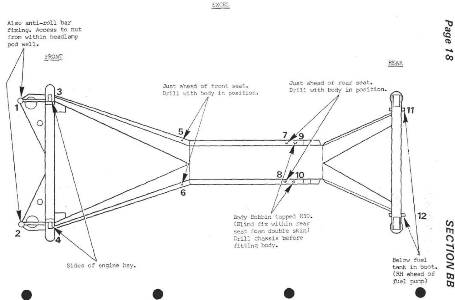
Esprit.
Twelve fixings are used to attach the body to the chassis. All chassis fixing points are plain holes except numbers 13 & 14 (Federal only) which are tapped M10. Holes1 & 2 (8mm) and 3 & 4 (10mm) are drilled with the body in position.
Aluminium 'bobbins' are used in the body at all mounting points except 9 & 10 which holes are drilled through the timber/composite rear bulkhead.
After lowering the body onto the chassis, check that the pedal box mounting bosses are not fouling the body. Locate the body by inserting fixings 11 & 12 (13 & 14 on Federal cars) but do not tighten.
Insert spacers if necessary between the body and chassis at points 1 & 2 and drill chassis at these points through the body bobbins. Insert fixing bolts.
Similarly drill chassis at points 3 & 4 and insert fixings using spacer washers if necessary. Insert remaining fixings and tighten from the front of car rearwards.

BODY
SECTION BD - ESPRIT S3 & TURBO
| Operation | Page | |
| Windscreen Replacement | BD.1 | 2 to 7 |
| Tailgate Glass and Finishers | BD.2 | 7 |
| Rear Bulkhead Glass | BD.3 | 8 |
| Rear Quarter Glass | BD.4 | 8/9 |
| Door Window Frame | BD.5 | 9/10 |
| Door Drop Glass | BD.6 | 10/11 |
| Door Glass External Weatherstrip | BD.7 | 11/12 |
| Door Quarter Light Glass | BD.8 | 12/13 |
| Door Shell | BD.9 | 13 |
| Headlamp Pods | BD.10 | 13 to 15 |
| Front Bonnet Panel | BD.11 | 15 |
| Tailgate | BD.12 | 15 to 17 |
| Front Bumper | BD.13 | 17 |
| Rear Bumper and Spoiler | BD.14 | 17/18 |
| Engine Bay Ventilation | BD.15 | 18/19 |
| Decal Positioning | BD.16 | 20 to 25 |
| Glass Roof Abutment | BD.17 | 26 |
BD.1 - WINDSCREEN REPLACEMENT.
The windscreen is bonded to the body aperture with "Betaseal" adhesive/sealant. The following procedure must be adhered to in detail, paying particular attention to the cleaning and priming operations and using materials supplied with Betaseal Kit, A075B6158J.
NOTE: It is likely that the screen bright finishers will have to be renewed on screen replacement.
- Remove the interior 'A' post finishers, and screen header rail. (see section 'V')
- Remove windscreen exterior bright trim and wiper arm.
- Bore a small hole through the Betaseal and insert a length of piano wire or similar (supplied in Betaseal Kit) approx. 1 metre long, through the hole. With the aid of an assistant inside the car, use a sawing action to cut through the Betaseal and free the screen from the car. Alternatively, use cutting out tool A075B6169. Take great care not to damage the interior trim or paintwork during this operation.

- Remove excess Betaseal from the screen aperture with a sharp blade. Note that it is not necessary to remove all traces of the sealant but a uniform surface must be available for bonding the new screen.
- Dry fit the screen and examine the screen/body joint conformity. If necessary, use props to support the central portion of the aperture top flange. Mark any areas of significant non-conformity in order that an additional bead of Betaseal may be applied to the body flange in that local area only, before screen fitment.
- Make up the two spacers to support the screen in its aperture and provide a 6 - 7 mm gap between screen top edge and body.
- Clean up the laminated edge of the glass with a sharp knife.
- Cut the special paper provided in the Betaseal Kit into two. With one half use Wipe Cleaner No. 4 to clean the perimeter of the glass and the whole bonding area of the body flange. With the other half, wipe dry the surfaces cleaned.
- Remove the grooved sections from the primer applicator guide to obtain a 20 mm width band. (i.e. full applicator width.)

-
Shake glass primer container for at least 30 seconds before opening. Pour glass primer into plastic bottle and fit applicator guide and felt pad. Apply primer around perimeter and laminated edge of glass. Also, prime whole of body aperture flange.
-
Cut the Betaseal application nozzle as shown below.
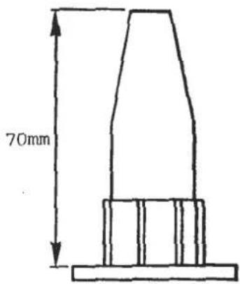
A. Cut off top of nozzle at a height of 70 mm as shown.
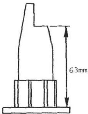
B. At a height of 63mm cut horizontally across to the centre line. From the top, cut vertically downwards along the centre line to meet first cut as shown.

C. Measure width of horizontal cut from inside surface to the plane of the vertical cut. If this dimension is less than 5mm cut further across (at 63mm height) and then downwards as in b) until a width of 5mm is achieved.
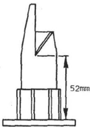
D. Cut a 'V' notch as shown by continuing one side of the vertical cut downwards to a height of 52mm, and intersect with a diagonal cut from the point of maximum width.
SECTION BD
- Push in bottom of Betaseal cartridge and remove desiccant Pierce membrane in cartridge thread, screw on application nozzle and insert in cartridge gun.
- Holding the gun at a right angle to the edge of the glass and leaning slightly inboard, extrude a continuous bead of Betaseal on the perimeter of the glass, using the edge of the glass and shape of the nozzle as a guide. This method will give the bead the correct dimensions and also make the top of the bead collapse inboard, reducing the amount of material squeezed out of the joint or assembly.

- Push eight 4 mm spacer blocks A075U0588Z into the Betaseal from the inside of the bead in the positions shown.
- Fit the screen onto the body and use the two spacers made in paragraph 6 to support the glass whilst the Betaseal cures. Press gently all round the edge of the glass to ensure uniform compression of the joint.
- Water test before fitting bright trim. If any leakage is found, mark the spot and dry the bead with a blow dryer or similar. Extrude a small amount of Betaseal from the outside on the suspected area in order to ensure the vehicle is waterproof.
Do not fit screen bright trim until the Betaseal is sufficiently cured not to be disturbed. This may take up to 6 hours depending on atmospheric conditions.
-
Dry fit the screen bright finishers and adjust the length and corners of the top finisher if required. Abrade the underside of the finishers to remove the anodised surface and then score to produce a key for the adhesive. Degrease surfaces using acetone or methylated spirit.
-
Adhesive to be used is 3M's 8101 parts A & B, part numbers A075U6073F and A075U6074F respectively.
Mix parts A & B of adhesive in equal parts until a uniform colour. Apply a short bead of adhesive approximately 40 mm long in 10 places. as shown.

- Fit the three sections of trim and tape firmly in position. Wipe off excess adhesive. The adhesive will cure within one hour to provide handling strength at 73°F, whilst 8 hours is required for full cure. Curing will be slower at cooler temperatures.
NOTE: Under no circumstances must silicon, dust, wax etc. be present in the atmosphere during bonding.
- After curing apply black "Silastic" around the bright trim outer edge to seal, and black strip A082U6072V to the lower edge of the glass. Refit wiper arm and interior trim.
Spillage of material.
a) Any spillage of Betaseal onto unprimed glass can be readily peeled off after it has cured.
b) Any spillage onto the body can be removed with either Wipe Cleaner No. 4, or white spirit.
Shelf life.
a) Betaseal has a shelf life of over 6 months at ambient temperature in the original unopened package.
b) Glass primer becomes spongy after a period of time when exposed to the air. If the material is spongy DO NOT USE.
Always use glass primer immediately on opening, and replace lid after use.
Contents of Betaseal Kit A075B6158J.
i) One part adhesive sealant Betaseal 71904 in a 300 cc cartridge, standard viscosity.
ii) Cartridge applicator nozzle.
ix) Special cleaning paper.
x) 4 off rubber spacing blocks, approximate size 10 x 14 x 20 mm.
BD.2 - TAILGATE GLASS.
Series 3.
The tailgate glass is fitted using Betaseal in a similar manner to the windscreen.
To replace a tailgate glass and finishers, follow the windscreen replacement procedure BD.1. but position the spacer blocks A075U0588Z as follows.
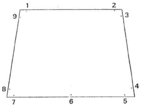
Turbo.
The tailgate glass is fitted using Betaseal in a similar manner to the windscreen. To replace a tailgate glass, follow the windscreen procedure BD.1. with the following notes.
i) The ABS moulding around the inside of the aperture is secured using black Silastic.
ii) Six spacer blocks, A075U0588F are used around the periphery of the glass.
BD.3. - REAR BULKHEAD GLASS.
The rear bulkhead glass is bonded to its composite surround using either Solbit thermo-electric or Betaseal polyurethane bonding medium. The surround is then screwed to the timber bulkhead.
To replace glass.
- Release both seatbelts from their sill mounting points, and on Federal cars, the tailgate release handle assembly.
- Pull off the door seals from the top rear of each door aperture, release the screws securing the rear bulkhead trim panel, and remove the panel, disconnecting the interior lamp.
- Release the screws securing the glass surround to the bulkhead, and remove.
- It may prove possible (dependant on length of service) to push out the glass from the surround after re-heating the Solbit by applying 19 volts to the Solbit ends for several minutes. Alternatively use 'piano' wire to cut out the glass.
- Remove remaining bonding medium from surround and glass.
- Follow the Betaseal procedure detailed in BD.1. to clean, prime and bond the glass to its surround, using six spacer blocks A075U0588Z around the periphery of the glass.
- Refit the surround to the bulkhead, using black Silastic to seal.
- Refit trim panels, seat belts, etc.
The rear quarter windows are fitted using 'Solbit' thermoelectric bonding medium.
To replace.
- Carefully remove the ABS finisher which is stuck to the glass with double sided tape.
- It may prove possible (dependant on length of service) to push out the glass after re-heating the Solbit by applying 9 volts to the Solbit ends for several minutes. Alternatively use 'piano' wire to cut out the glass, but first remove the air scoop/extractor and take precautions as necessary to protect the paintwork.
- Remove remaining Solbit from the body and glass.
- Clean the inside periphery of the glass, and the whole of the body bonding area with methylated spirit, and wipe dry.
-
Apply Solbit Primer to the areas cleaned in 4.
-
Cut a 1.3 metre length of 8 mm Solbit and strip each end to expose 12 mm (0.5 in.) of the internal copper wire. Connect the ends to a variable transformer and apply 9 volts to the Solbit until its surface is tacky. Disconnect Solbit from power source.
- Starting at the centre top, apply the Solbit around the quarter light aperture and cross over at the end. Fit two spacer blocks A075U0588F into the top of the Solbit strip along the aperture lower edge.
- Fit the glass onto the aperture and reconnect the Solbit to the 9 volt power source. Apply gentle pressure to the glass. After about two minutes, the Solbit will start to flow and the glass will be felt to move slowly inwards. When the lower edge of the glass is felt to contact the spacers and the rest of the Solbit is similarly compressed STOP applying pressure but continue to apply current for a further ten minutes whilst supporting the glass using tank tape. Smooth off or remove excess extruded Solbit.
- Clean the outside perimeter of the glass, and inside surface of the ABS finisher with methylated spirit. Wipe dry.
- Apply Solbit Primer to the inside surface of the ABS finisher, and when dry, apply double sided tape B075U6070V. Peel off the backing paper and fit the finisher to the glass.
- Refit the air scoop/extractor.
BD.5. - DOOR WINDOW FRAME.
- To remove:- Peel back the trim material inside the interior door handle and loosen the three screws securing the handle assembly to the door. Slide out the upper and lower halves of the door handle plastic surround.
- Remove the screw securing the lower front and lower rear of the trim panel, and unhook top lip of panel from door top edge.
- Remove PVC sheeting from door shell. Disconnect window motor wires, release the four nuts securing motor bracket to door beam and remove window motor, sliding its operating arm from the drop glass channel.
- Release the two M6 nuts securing the carriage plate to the drop glass channel and separate. Tape the drop glass to the window frame.
- Remove the five nuts securing the window channel to the door beam and the two screws securing the channel to the upper rear of the door shell. Note that the bolt heads are retained

in longitudinal channels on the door beam so that the window frame must be eased off the bolts before it may be withdrawn with glass, from the door.
BD.6. - DOOR DROP GLASS.
- Remove the door window frame from the door (BD.5.)
- It may prove possible to remove the lift channel from the glass after applying 3 volts to the Solbit thermo-electric bonding medium for several minutes.
- Before fitting a lift channel to the glass, thoroughly clean the lower edge and sides of the glass and inside channel, with methylated spirit.
- Apply Solbit Primer to the lower edge and both lower sides of glass in a band 12 mm ( 1/2 in.) wide. Also apply to whole inside surface of channel. Allow to dry.
-
Strip both ends of a 450 mm (18 in.) length of 10 mm diameter Solbit to expose 12 mm ( 1/2 in.) of internal copper wire. Connect to a variable transformer and apply 3 volts to the Solbit until its surface becomes tacky (10 - 13 secs.). Disconnect supply and place Solbit into lift channel.
-
Position channel on lower edge of glass with operating arm guide to the inside (carriage plate bracket to rear) and the rear end of channel 120 mm from rear edge of glass.

- Reconnect electrical supply to the Solbit and as it starts to flow, push channel fully onto glass. Continue to apply current for a further five minutes while removing or smoothing out extruded Solbit. Disconnect supply.
- Fit drop glass into frame and refit door window frame into door. Adjust carriage plate to obtain smooth rise and fall of the drop glass before installing window motor. Refit door trim.
BD.7. - DOOR GLASS EXTERNAL WEATHERSTRIP.
To remove weatherstrip, first remove the door interior trim panel (see section BC.5.) to gain access to the three nuts clamping the weatherstrip assembly to the door shell. Loosen the nuts and ease the assembly away from the door.
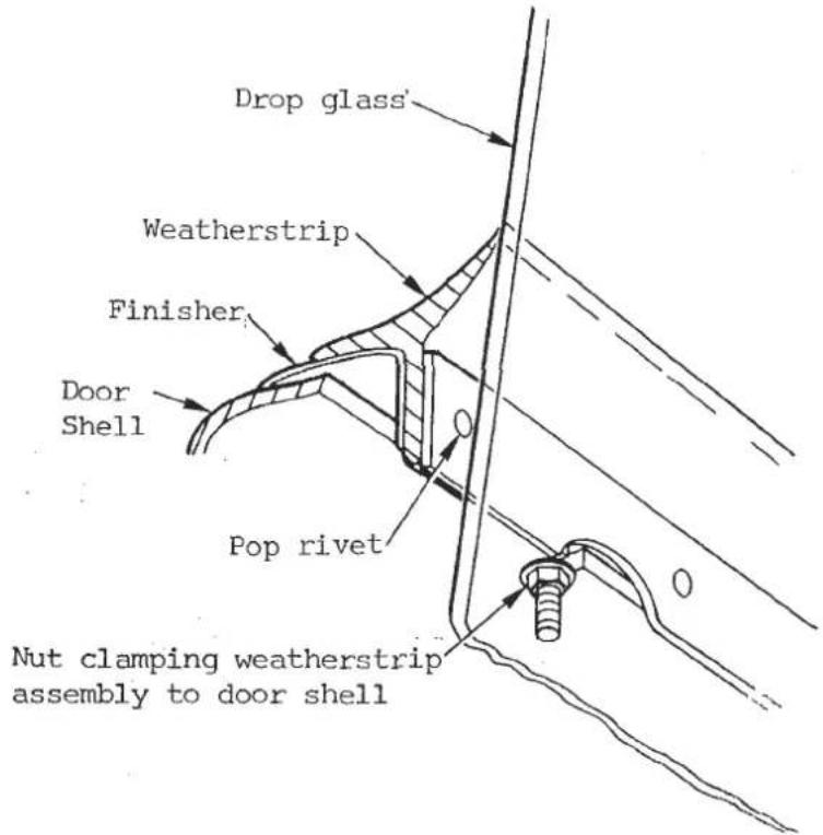
Drill out the pop rivets to replace the rubber seal.
When refitting, apply a thin bead of Silastic to the top edge of the door shell before installing the weatherstrip assembly. Ensure the seal lies against the glass before tightening nuts. Overtightening nuts will distort the finisher.
BD.8. - DOOR QUARTER LIGHT GLASS.
- to remove: Remove the door window frame from the door (Section BD.5.). It is not normally possible to remove the quarter glass from the frame without breakage.
- Remove remaining glass and Solbit from inside the quarter glass channels.
- To replace: Clean the front and rear edges and periphery of new glass with methylated spirit. Also inside window frame channel.
- Apply Solbit Primer to the edge of the glass and a 6 mm (1/4 in.) wide band on both sides of the front and rear edge of the glass. Apply Solbit Primer to all surfaces inside the frame channel.
- Strip both ends of a 1.4 mm (4 ft 6 in) length of 10 mm Solbit to expose 12 mm ( 1/2 in.) of internal copper wire and connect to a variable transformer or 6v battery. Apply 6 volts to the Solbit until its surface becomes tacky.
- Disconnect the power source and position the Solbit on the primed edge of the glass. Introduce glass and Solbit into the window frame and push home, until the Solbit contacts the window frame.

- Connect the Solbit to the 6volt power source and apply pressure to the lower edge of the glass, and as the Solbit starts to flow, push the glass fully into the
SECTION BD
window frame. Continue to apply current for a further six minutes whilst keeping the glass central in the frame channel and smoothing out excessive Solbit to leave a smooth surface level with the edge of the window frame.
- Disconnect power source, cut Solbit ends flush with the corners of the glass and replace door window frame.
BD.9. - DOOR SHELL.
The GRP door shell is secured to the alloy door beam by four bolts as shown and may be removed from the car by sliding off the door beam (in situ) after removing the door window frame (BD.5) and latch mechanism.
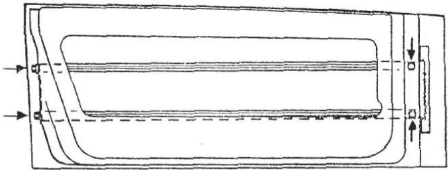
BD.10 - HEADLAMP PODS.
Pivot.
Federal cars use a pod pivot ball joint at each side of each pod, the outboard ball joint being rivetted to the body, whilst the inboard ball joint is fixed to the pod. The inboard pivot bolt passes through the pod ball joint and then through the bonnet ball joint (fixed to the body) before threading into the bonnet hinge bar.

Domestic and RoW cars use a body mounted ball joint on the outboard side, and on the inboard side, a hinge pin pivotting in bushes mounted both in the pod and body, and carrying on its 'overhung' outboard end, the bonnet hinge.

To remove.
To remove a headlamp pod, unplug the bulb connectors and release the pod actuating link. Release the pod outboard pivot bolt and support the bonnet panel before releasing the inboard pivot bolt (Federal) or removing the split pin and sliding out the hinge pin (DOM/ROW).
On refitting ensure that the pod is located centrally using spacer washers if necessary, and that the pod pivots freely before connecting the actuating link.
Adjustment
The pod down position is adjusted by altering the actuating link length. Slacken the locknut at each end of the actuating link and turn the link rod to change its effective length as required.
Tighten locknuts.
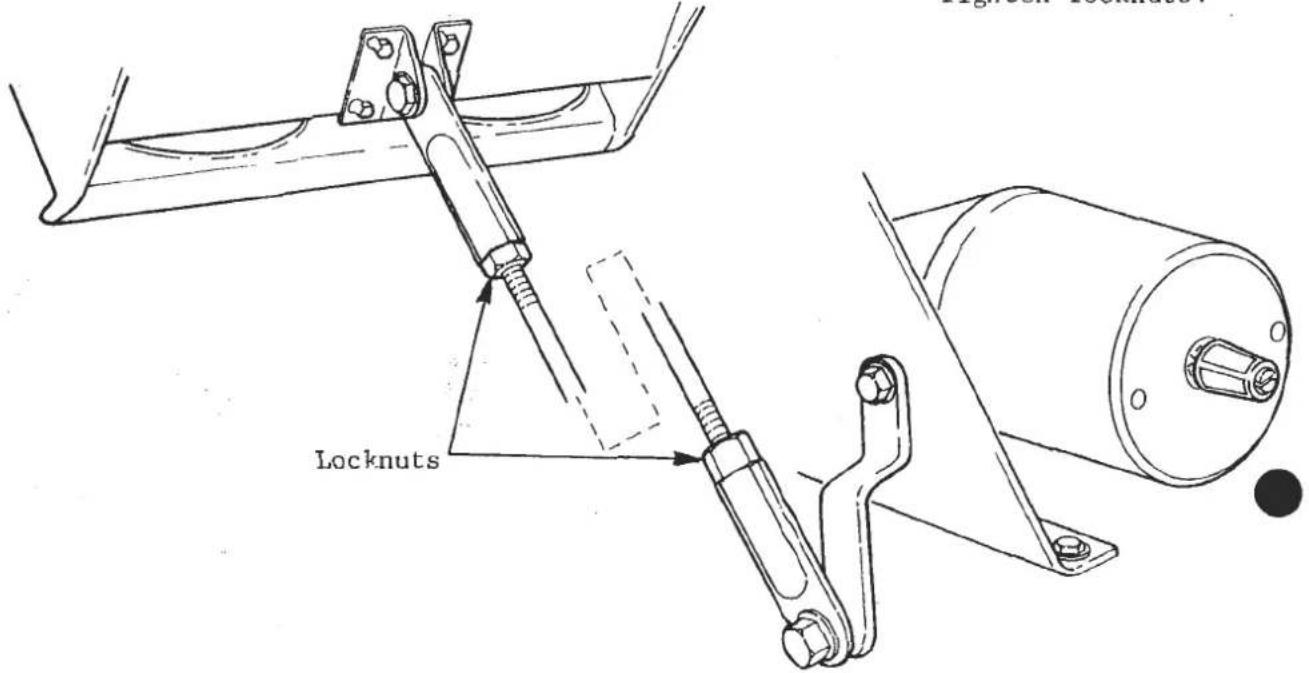
SECTION BD
Always check headlamp beam setting after any pod adjustment is made since the pod up position will also be altered.
BD.11 - FRONT BONNET PANEL.
The front bonnet panel is hinged at its front edge by two individual hinges on DOM/ROW cars and by a cross linkage bar on Federal vehicles. The hinge pivots are incorporated with the headlamp pod inboard pivots. (see section BD.8.)
The striker hoops fitted at each rear corner of the bonnet panelengage with two catch discs mounted on the bulkhead. The catch discs are connected via adjustable link rods to a cross bar with a release handle on the drivers side.
Adjustment.
The shut gap and height of the bonnet front edge may be adjusted via hinge slots and spacer plates. The sideways fit of the panel is controlled by spacer washers at the hinge pivots.
At the rear edge, the catch disc position should be similar on both sides with the slot pointing slightly upwards in the 'released' setting. Striker plate spacers and slots are used to adjust the bonnet rear edge height and catch engagement respectively.
BD.12. - TAILGATE
The tailgate panel is hinged at each top corner (except on sun roof models) to a bobbin bonded into the roof structure. On sun roof models each hinge pivot takes the form of a bracket bolted to the roof.
Three types of tailgate latching system have been employed. Domestic/R.O.W. Turbo models have a key lockable external release knob on the rear spoiler, which is connected via a link rod to the right hand tailgate latch. Right and left hand latches are interconnected by a cross bar and when released allow the tailgate to be opened, assisted by two gas struts. On early cars, the struts were anchored in the tailgate aperture, but later cars used an anchor position at the front of the engine bay for greater opening assistance.
Series 3 models use a cable operated release activated via a pull handle in the drivers door 'B' post. Prior to 1985, a spring plunger alongside each catch, raised the tailgate on release sufficiently to enable it to be opened fully by hand. From 1985, the spring plungers were deleted and a recess provided in the tailgate lower edge and body to permit a handhold
U.S.A. Turbo models utilise a cable release activated via a pull lever in the drivers side rear bulkhead. This is connected to a catch plate in each lower corner of the tailgate aperture. Two gas struts are used to assist tailgate opening and support it in the fully open position.
The release lever pivot is secured by a nut and integral stud which passes through the bulkhead just outboard of the seat belt reel.
anchorage position of the gas struts was changed from the tailgate aperture (early models) to the front engine bay in order to improve opening assistance.

Removal The tailgate is most easily removed by releasing the gas struts and then removing the hinge blade to tailgate bolts. Note that the tapping plate for the hinges is retained in the tailgate by a third fixing further along (gas strut anchor S3 and early Turbo). On no account should all three fixings be removed at the same time since the plate is captive within the tailgate double skin and may not easily be repositioned.
Removal of the hinge blade pivot bolts will (except on glass roof models) necessitate removal of the exterior capping rail and interior rear bulkhead trim. The capping rail is fixed by screws and Silastic along its lower edge and retained along its top edge by the lip of the bright finisher strip. After removing the capping rail and rear bulkhead trim panel (VB.8) the Nyloc pivot bolt nuts may be released and the pivot bolts withdrawn.
Note that the hinges are used to transmit current to the heated rear screen, with one wire on each side being fitted beneath the pivot bolt nut and then taken from the tailgate tapping screw to the screen.
On'glass roof' cars a pivot bracket is bolted to the roof on each side so that after removal of the tailgate and pivot brackets the hinge pivot bolt may be removed without disturbing the capping rail.
Latch adjustment.
On Series 3 tailgates, slots and shim plates are provided for adjusting striker position and depth. The height of each catch assembly may be adjusted after slackening the catch to body screws and catch bracket to rear panel support strut screws. A single cable is used to release both catches and is adjusted to remove slack by means of a solderless nipple at the left hand catch.
Federal Turbo models use striker pins in the tailgate panel adjustable for height after slackening the locknut. The catch assemblies in each rear corner of the tailgate aperture are adjustable for position after slackening their two mounting screws. The single release cable abuts against the left hand catch before being retained at the right hand catch by a solderless nipple.
The carburettor air box is fed with air via an intake silencer located above the right hand fuel tank and a Venturi hose strapped to the wheelarch. Air is thus drawn from the rear luggage compartment into which is fed fresh

air from the left hand luggage compartment vent, connected to the left hand 'ear' intake vent. In this way an airflow is maintained through the luggage compartment, aiding demisting of the tailgate glass.
Turbo.
On Turbo models, the louvered tailgate panel seals around the engine lid aperture and draws air out from the engine bay when the car is moving. Cool air is fed into the bottom of the engine bay via the NACA duct in each sill. The engine airbox is fed from the right hand intake vent 'ear' behind the rear quarter window.
On Federal cars the left hand intake 'ear' is used to supply additional cooling air to the carburettor area via a duct within the engine cover lid. The engine bay cooling fan fitted in the engine cover lid is designed to aid cooling after the engine has been switched off, by blowing air down over the carburettors. The fan will operate during a period of 15 minutes after switching off the ignition if engine bay temperature exceeds 85°C (thermal switch fitted to left hand front underside of engine cover lid). An inhibitor switch fitted into the top of the ignition box isolates this circuit when the engine lid is raised.
BD.16. - DECAL POSITIONING
ESPRIT S3 - Early '84 Model Year



ESPRIT S3 - Prior to '85 Model Year (Except Early '84 Model Year)

ESPRIT S3 - '85 Model Year On


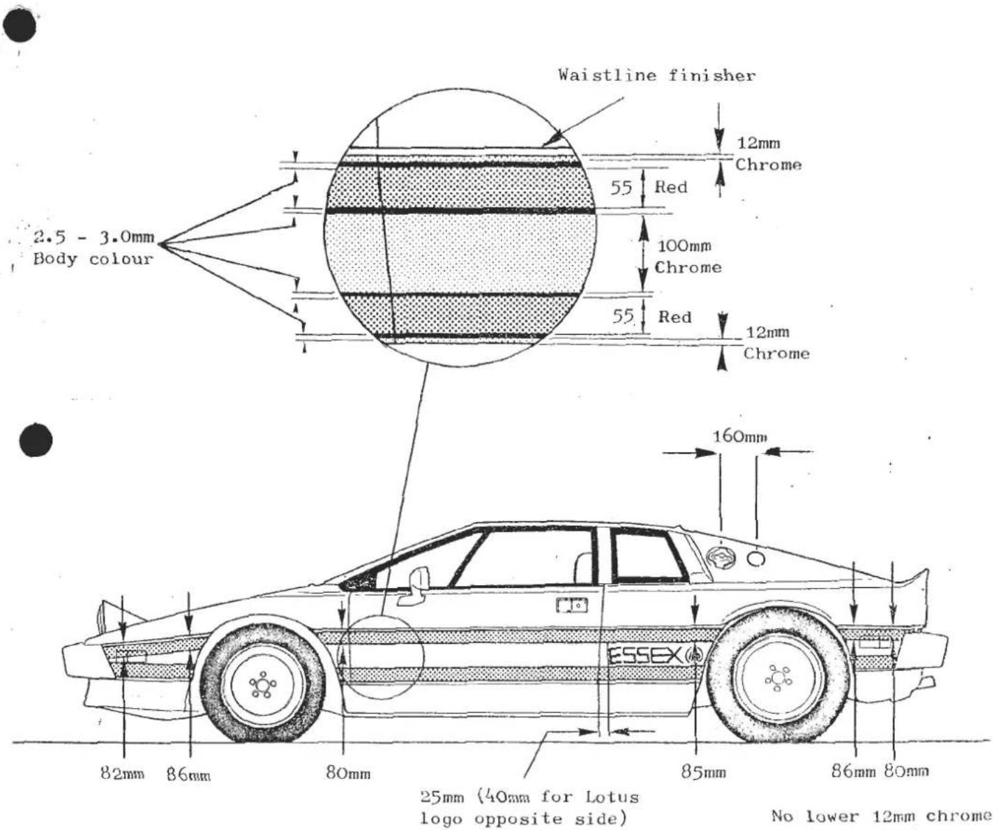

TURBO - Prior to '85 Model Year


BD.17 - GLASS ROOF ABUTMENT
In early 1985, a positive stop abutment was added to the glass roof rear catch support brackets, such that the roof is clamped shut against two rubber buffers. An improved 'over centre' catch action results in more rigid retention of the roof panel with less liability for rattles and squeaks. The shimming of the rear catch support brackets to the body may then be adjusted for optimum panel height and seat compression.
The revised catch support brackets (D082U4974F) and rubber buffers (X046B6113Z) are directly interchangeable with the earlier brackets.

FRONT SUSPENSION
SECTION CB - ESPRIT S3 & TURBO : PRIOR TO '85 MODEL YEAR
| Operation | Page | |
| General Description | - | 2/3 |
| Lubrication | CB1 | 4 |
| Geometry | CB2 | 4 |
| Castor Adjustment | CB3 | 5 |
| Front Wheel Alignment | CB4 | 6 |
| Front Suspension Disassembly | CB5 | 6 |
| Front Hub Adjustment | CB6 | 6 |
| Wheel Bearing Replacement | CB7 | 7 |

Page 2
SECTION CB
nt Suspension - General Layout
GENERAL DESCRIPTION
The front suspension is fully independent with upper wishbones, single lower links, and an anti-roll bar providing longitudinal location for the lower links. Co-axial coil springs and oil filled telescopic dampers react on the lower link.
A stub axle secured in each vertical link, carries the wheel hub on two taper roller bearings, adjustable for endfloat.
Key to Front Suspension General Layout Drawing
- Front Hub
- Brake Disc
- Wheel Bearing, inner
- Wheel Bearing, outer
- Oil Seal, Front Hub
- Stub Axle
- Dust Cap
- Vertical Link
- Steering Arm
- Caliper Mounting Plate
- Dust Shield
- Upper Ball Joint
- Wishbone Arm
- Pivot Bush, Wishbone
- Stud, Wishbone Pivot
- Lower Trunnion
- Bush Kit, Lower Trunnion
- Seal, Trunnion Top
- Bolt, Trunnion to Lower Link
- Lower Link Assembly.
- Bush, Lower Link Pivot
- Anti-Roll Bar
- Bush, Anti-Roll Bar to Lower Link
- Distance Tube
- Washer, Anti Roll Bar to Lower Link Bush
- Mounting Rubber, Anti Roll Bar to Chassis
- Clamp Plate
- Damper Assembly
- Bolt, Damper to Lower Link
- Road Spring
- Spring Seat
CB.1.- LUBRICATION
The only items of the front suspension requiring periodic lubrication, are the front wheel bearings and the lower trunnion swivel joint.
At the recommended service interval, repack the hub with grease, (See Section C and lubricate the lower trunnions.
Lower Trunnions: It is ESSENTIAL that a recommended EP90 grade oil is used to lubricate the trunnions, and NOT grease. Remove the plug shown arrowed, and fit a threaded grease nipple into the vertical link. Apply an oil filled grease gun to the nipple, and pump until oil exudes from the trunnion top seal.

CB.2.- GEOMETRY
Under normal service conditions, it should only be necessary to check the front wheel alignment. A full geometry check is only necessary following front suspension repair, or if excessive tyre wear is evident, or steering difficulties experienced. Both wheel alignment and castor angle are adjustable, but camber and steering axis inclination (K.P.I.) are set during manufacture, and are non-adjustable.
At ride height of 170mm :- Measured at front chassis box section
| Camber | minys 0° 30' ± 0° 15' |
| Castor | 3° ± 0° 30' (within 0° 30' side to side) |
| K.P.I. | 9° ± 0° 30' |
| Toe-in | 2mm overall ± 1mm |
CB.3.-CASTOR ADJUSTMENT
Castor adjustment is affected by fitting shims between the anti-roll bar mountings and the chassis. Two types of mounting have been used.
i). Up to VIN 82/85D 1262, 82/85 A/E/G/H/S0410 exc. 0399 and 0400 C/F, B/C/F/K 0103.
Spacer washers A075W4028Z, 2.5 mm thick, are fitted between the mounting and chassis, on both upper and lower bolts. On each side of the car, an equal number of washers must be used top and bottom, up to a maximum thickness of three washers.
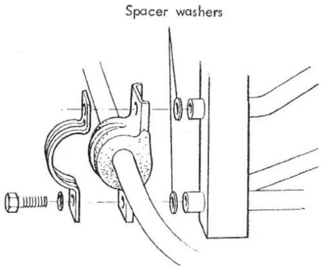
ii). From VIN 82/85D 1263, 82/85 A/E/G/H/S 0411 plus 0399 and 0400 C/F B/C/F/K 0104. Shim plates A082C4052, 2mm thick, may be slid in behind the mountings after slackening the bolts. Up to four shims may be used on each side.

CB.4.-FRONT WHEEL ALIGNMENT
To adjust the front wheel alignment, slacken the track rod end locknuts and steering rack bellows outer clips. Turn each track rod the same amount, without damaging the surface and after tightening the locknuts check that the same number of threads are left showing at each side. When the adjustment is correct tighten the bellows clamps.
CB.5.- FRONT SUSPENSION DISASSEMBLY
CAUTION: Because the upper and lower road spring abutments are the chassis and lower link respectively, it is ESSENTIAL that spring compressors are used before disconnecting either end of the damper, or the lower link from the chassis. Failure to do so could result in personal injury.
All suspension rubber bush pivots, must be tightened only at ride height (150 and 175 mm at front and rear of chassis centre box section).
On the anti-roll bar to lower link bush fixing, note that a special chamfered washer is fitted between the anti-roll bar and the lower link front bush, in order to provide for fillet clearance. Ensure this washer is fitted the correct way round.
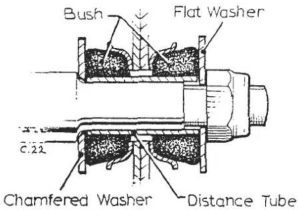
Note when fitting the damper that a flat washer is used on both sides of the damper lower bush inside the lower link.
CB.6.-FRONT HUB ADJUSTMENT
Adjustment: Remove the road wheel followed by the hub dust cover (A) and split pin (B).
Tighten the hub nut to 0.7 - 0.8 kgf.m. (5 - 6 lbf.ft.) whilst rotating the hub to ensure bedding of the taper roller bearings. Slacken the nut sufficiently to obtain a hub endfloat of 0.08 - 0.13 mm (0.003 - 0.005 in.) measured with a dial gauge. Insert the split pin and refit the hub dust cover.
CB.7. - WHEEL BEARING REPLACEMENT
- Remove the road wheel. Release the caliper fixing bolts, and support caliper clear of disc without straining brake hose.
- Remove hub dust cap (A) split pin (B), nut (C), washer (D) and pull off the hub assembly (E) complete with bearings.

- Prise out the oil seal from the inboard side of the hub, and remove the inboard inner race and roller assembly. Both outer races may now be driven from the hub using a soft metal drift at alternate sides of each race.
- Fit new outer races into the hub using a press.
- Pack the new bearings with an approved Lithium based wheel bearing grease, and work well into the roller cages. Coat the inside of the hub outer races and cap with grease.
- Insert the inboard bearing roller assembly and inner race, and retain with new oil seal.
- Mount the hub assembly onto the spindle and fit the outboard roller assembly and race, retaining washer and nut, and adjust the bearings (see above) before fitting split pin and dust cap.
- Refit brake caliper, torque tightening fixing bolts to 8.3 kgf.m. (60 lbf.ft.) and road wheel.
- Torque wheel retaining bolts to 9.0 kgf.m (65 lbf.ft.).
FRONT SUSPENSION
SECTION CC - ESPRIT S3 & TURBO: 1985 MODEL YEAR ONWARDS
| Operation | Page | |
| General Description | - | 2 to 4 |
| Geometry | CC1 | 4 |
| Castor Adjustment | CC2 | 4/5 |
| Suspension Disassembly | CC3. | 5/6 |
| Front Wheel Bearings | CC4 | 6/7 |

page 2
SECTION CC
Key to Suspension Layout Diagram
- Vertical Link
- Steering Arm
- Setscrew, M12 x 35, Arm/Link
- Spring Washer, Arm/Link
- Bolt, M12 x 45, Arm/Link
- Nut, Nyloc, M12
- Shield, Brake Disc
- Setscrew, Disc Shield
- Flat Washer, Disc Shield
- Front Hub
- Inboard Bearing, Front Hub
- Outboard Bearing, Front Hub
- Brake Disc, Ventilated
- Bolt, Brake Disc to Hub
- Washer, Disc to Hub
- Grease Seal, Front Hub
- Claw Washer, bearing Retaining
- Nut, Bearing, Retaining
-
Split Pin, Locking Cap
-
Locking Cap, Bearing Nut
- Grease Cap, Hub Bearing
- Arm, Upper Wishbone
- Pivot Bush, Upper Wishbone
- Stud, Upper Wishbone Pivot
- Buffer Washer, Pivot Bush
- Nut, Nyloc, 1/2" UNF
- Locknut, 1/2" UNF
- Shim Washer, Castor Adjust
- Ball Joint, Upper
- Nut, torqloc, 7/16" UNF
- Bolt, M8 x 100, Ball Joint
- Bolt, M8 x 60/65, Ball Joint
- Nut, Nyloc, M8
- Washer, Plain
- Shimplate, Castor Adjust
- Lower Wishbone
- Pivot Bush, Wishbone Rear
- Pivot Bush, Wishbone Front
-
Bush, ARB/Wishbone
-
Ball Joint, Lower
- Nut, Nyloc, M14
- Pivot Bolt 1/2" UNF x 6"
- Nut, Nyloc, 1/2" UNF
- Pivot Bolt, 1/2 " UNF × 2 3/2 "
- Nut, Nyloc, 1/2" UNF
- Anti-Roll Bar
- Bush, ARB/Chassis
- Clamp, ARB/Chassis
- Setscrew, M12 x 35
- Washer
- Nut, Nyloc, M12
- Abutment Plate, Spring/Damper
- Washer, Plate/Chassis
- Nut, M8 Plate Chassis
- Insulator, Spring Top
- Road Spring
- Damper
- Bolt, 1/2" UNF × 31/2"
- Nut, Nyloc, 1/2" UNF
- Bush Kit, Damper Top Stem
- Blanking Plug, Plastic
GENERAL DESCRIPTION
The front suspension is fully independent with upper and lower wishbones together with concentric damper/spring assemblies and an anti-roll bar.
A stub axle, integral with the non-handed vertical link (hub carrier) carries each front hub on two taper roller bearings, adjustable for endfloat.
CC. 1 - GEOMETRY
Under normal service conditions, it should only be necessary to check the front wheel alignment. A full geometry check is only necessary following front suspension repair or if excessive tyre wear is evident, or steering difficulties experienced.
The recommended method of measuring front wheel alignment is by the use of parallel bars as described in section DB so that the rear wheel alignment may be checked at the same time.
Before measuring suspension geometry set car to ride height of 170mm below chassis front cross member, 170mm below rear lower link chassis brackets.
| Camber | 0° 30' negative + 0° 30' |
| Castor | min 1° 45' max 3° (Within 0° 30' side to side) |
| K.P.I. | 9° 23' nominal |
| Toe-in | 1.6mm each side + 0 - 1mm |
CC. 2 - CASTOR ADJUSTMENT
Cars prior to VIN 82/85 D 1937 (Dom) FF 0602 (U.S.A.) may be fitted with castor adjustment shims 'A' and 'B' as illustrated. These shims are available in various thicknesses:
| Shim Washer | 'A' 1.5mm | A082C4091 |
| '' '' | 'A' 3.0mm | A082C4092 |
| '' '' | 'A' 6.0mm | A082C4093 |
| Shim Plate | 'B' 1.5mm | A082C4090 |
| '' '' | 'B' 3.0mm | A082C4089 |
Shims may be fitted up to a maximum thickness of 6.0mm to correct castor if necessary.
Important The same thickness shim pack must be used at location 'A' and 'B'. As a rough guide, fitment of 3.0mm shims at 'A' and 'B' will result in an increase in castor of approx. 10/2 .
Cars from and including VIN 82/85 D 1937 (Dom) FF0602 (USA) have a shortened chassis fixing tube for the top wishbone pivot stud, and 6mm of shim washers 'A' distributed between the front and rear of the chassis at this point. In extreme cases, these cars may be fitted with additional shims 'A' and 'B' as detailed above.
Caution in all cases ensure that the top wishbone pivot stud and ball joint bolts have sufficient engagement through their Nyloc nuts. If necessary, replace the pivot bolt front Nyloc and locknut with two locknuts (i.e. one Nyloc at rear and two locknuts at front). A 5mm longer ball joint outer bolt (M8 x 65) is available part no. A075W2044.
CC. 3 - SUSPENSION DISASSEMBLY
See exploded diagram for general layout
Caution The road spring lower platform is integral with the damper lower body, while the spring top platform/damper abutment is bolted to the chassis. Under no circumstances therefore may the damper top stem nuts be removed unless the spring/damper assembly is removed from the vehicle and the spring compressed in an hydraulic press or similar.
Spring/damper removal: These two components must be removed from the vehicle as an assembly. Release the damper to lower wishbone fixing, and the four nuts securing the spring top platform to the chassis, and remove assembly to bench.

Note that early '85 MY cars used parallel coil springs, which were superceded by conical springs with the greater diameter fitted lowermost. The diameter of the spring seat on the damper body is correspondingly increased for use with conical springs. If replacing a spring or a damper of the earlier 'parallel spring' type, then the later 'conical spring' type components should be fitted as an assembly.
Before the spring/damper assembly may be further dismantled, it is necessary to compress the spring. Conventional spring compressor clamps may not be suitable due to the close coiled nature of the compressed spring. Use special tool T000 or hydraulic press with suitable adaptors to compress the spring before removing the damper top stem nuts and rubber bush. After unloading the spring, the individual components may be replaced.
The anti-roll bar fixing into the lower wishbone is by push fit only. Use rubber grease on assembly. If replacing the lower wishbone anti-roll bar bush, ensure that the larger portion (in relation to its location groove) is fitted towards the front.
Suspension Re-assembly
On re-assembly, ensure that the upper and lower wishbone to chassis pivot bolts, and the damper to lower wishbone bolts, are tightened only with the car at ride height.
Ensure that plastic blanking plug A089U6089F is fitted into the open rear end of the lower wishbone front tube.
CC. 4 - FRONT WHEEL BEARINGS
-
The brake caliper must first be removed. In order to extract the caliper uppermost fixing bolt, it is necessary first to remove the cylinder swing release bolt, and swing up the cylinder until the brake pipe clears the caliper top fixing bolt.
-
Remove the hub nut and pull off the hub complete with brake disc.

- Prise out the inner oil seal and remove the centre assembly of the inboard bearing.

-
The outer races of both bearings may be removed from the hub using a drift as shown at alternate sides of the race.
-
Using a press, fit the outer races into the hub.
-
Pack the new bearings with a Lithium base wheel bearing grease and work well into the roller cages. Coat the inside of the hub, outer races, and cap with grease.

- Insert the inboard bearing centre and retain by pressing in the inner oil seal.
- Refit the hub onto the stub axle. Torque spindle nut to 3.0 kgf.m (22 lbf.ft) whilst rotating the hub to centralise the bearings. Loosen the nut, and retighten using only your hand on the 30mm socket. With a suitable spring balance, check the force needed to rotate the hub.
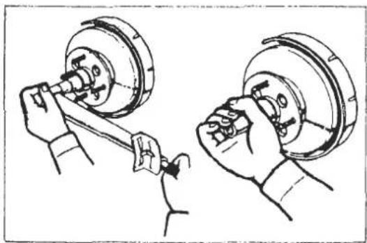

Preload:
With new oil seal
3 5 0 - 8 7 5 g
(0. 8 - 1. 9 lb)
With used oil seal
5 0 - 5 0 0 g
(0. 1 - 1. 1 lb)
- Using a dial gauge, measure the hub end float.
Maximum = 0.05mm (0.002 in.).
Install the lock ring and split pin, if necessary tightening the hub nut further by by the smallest amount required.
Refit brake caliper and torque bolts -
Caliper to vertical link 9.0kgf. m. (65 lbf.ft)
Cylinder swing release 1.6 - 2.4 kgf.m. (12 - 17 lbf.ft)
REAR SUSPENSION
SECTION DB - ESPRIT S3 & TURBO
| Operation | Page | |
| General Description | - | 2/3/4 |
| Geometry | DB1 | 4 |
| Rear Wheel Alignment | DB2 | 4/5 |
| Rear Suspension Reassembly | DB3 | 5 |
| Rear Wheel Bearing Removal | DB4 | 6 |
| Rear Wheel Bearing Installation | DB5 | 6/7 |
| Drive Shaft C.V. Joint Boot Replacement | DB6 | 7/8 |
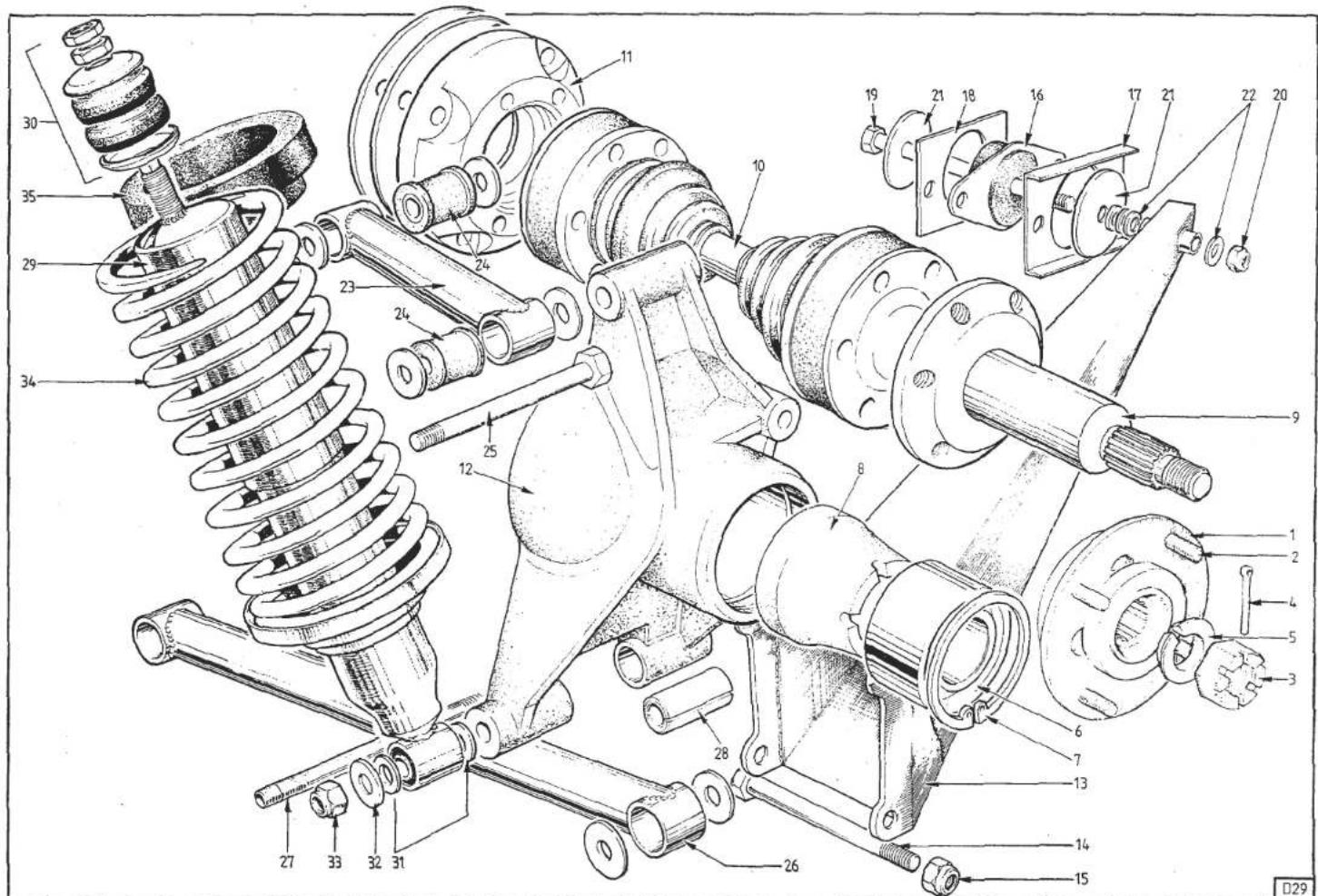
Page 2
SECTION DB
● Rear Suspension - General Layout
Key to Rear Suspension General Layout Drawing
-
Rear Hub
-
Stud, Wheel
-
Nut, Hub Retaining
-
Split Pin, Hub Nut
-
Cone, Hub Retention
-
Bearing, Rear Wheel
-
Circlip, Bearing Retaining
-
Spacer, Driveshaft/Bearing
-
Drive Shaft, Outboard
-
Drive Shaft, Intermediate
-
Adaptor, Driveshaft
-
Hub Carrier
-
Radius Arm
-
Bolt, Radius Arm to Hub Carrier
-
Nut, Nyloc, Arm to Hub Carrier
-
Mounting Rubber, Radius Arm Front
-
Reinforcing Plate, Radius Arm Mounting
-
Spacer, Radius Arm Mounting
-
Bolt, Radius Arm to Mounting
-
Nut, Nyloc, Radius Arm to Mounting
-
Washer, Large
-
Washer, Toe-In Adjustment
-
Top Link
-
Rubber Bush, Top Link
-
Bolt, Top Link to Hub Carrier
-
Lower Link
-
Stud, Lower Link to Hub Carrier
-
Split Spacer, Hub Carrier
-
Damper Assembly
-
Bush Kit, Damper Top Stem
-
Spacer Washer, Damper to Hub Carrier
-
Washer, Plain, Damper to Hub Carrier
-
Nut, Nyloc, Damper to Hub Carrier
-
Road Spring
-
Insulator, Road Spring
GENERAL DESCRIPTION
The rear suspension is fully independent with single upper and lower transverse links and box section trailing radius arms. Co-axial coil springs and oil filled telescopic dampers act on the aluminium alloy hub carrier.
An outboard drive shaft is carried in each hub carrier on a single sealed for life dual race angular contact ball bearing.
DB.1.- GEOMETRY
At ride height (170mm below rear lower link chassis brackets);
Camber : minus 0°30' ± 0°15'
Toe-In : 1.5mm each side + 0.5mm
DB.2.- REAR WHEEL ALIGNMENT
It is essential that rear wheel alignment is checked using equipment which measures individual wheel alignment. The most reliable and accurate method is considered to be the use of parallel bars, as used on production.
Two bars which are longer than the overall length of the car, and 4 axle stands are required. The bars should be obtained locally and should be of 'T' or square section and be sufficiently rigid to avoid significant bending or sagging between supports.
Set up the two bars on each side of the car at wheel centre height as shown in the diagram, so that A equals A, B equals B and C equals C.

Measure the distance from the bar to the RIM of the wheel concerned at front and rear of the centre line of the wheel. If the front dimension is greater than the rear dimension, the wheel has TOE-IN. If the rear dimension is greater than the front dimension, the wheel has TOE-OUT. The difference between the two measurements is the amount the wheel has TOE-IN or TOE-OUT.
Rear wheel alignment is adjusted by transferring shim washers between the inner and outer sides of the radius arm at its front mounting.

If correct adjustment cannot be obtained by transference of the shim washers, spacer plates may be used between the radius arm mounting and the chassis in the following combinations, in order to bring the correct setting within the range of adjustment afforded by the shim washers.
| EITHER | - | One 2mm spacer | A079D4051K |
| OR | - | Two 2mm spacer | A079D4051K |
| OR | - | One 6mm spacer | B079D4051K |
| OR | - | (One 2mm spacer(Plus One 6mm spacer | A079D4051K)B079D4051K) |
Ensure at all times that the mounting to chassis fixing bolts are of sufficient length to ensure full engagement of the nyloc fixing nuts.
NOTE: On final assembly, use a new nyloc nut on the bolt securing the radius arm to the rubber mounting, and torque tighten to 5.5 - 6.2 kgf.m (40 - 45 lbf.ft.) with the car at ride height.
DB.3.- REAR SUSPENSION REASSEMBLY
On reassembly of the rear suspension after component replacement or overhaul, check the rear wheel toe-in and adjust if necessary.
Tighten all upper and lower link pivot bolts and radius arm pivot bolt only with the car at ride height.
Note positions and assembly sequence of all pivot bolt washers before dismantling. Check general layout drawing at front of this section for damper to hub carrier fitment.
DB.4. - REAR WHEEL BEARING REMOVAL
- Remove hub carrier assembly from car.
- Remove split pin and hub retaining nut. Tap loose and remove the conical spacer.
- Using a suitable puller remove the hub.
- With the hub carrier on the bed of a press, press out the outboard driveshaft and spacer.
- Remove circlip retaining bearing in hub carrier, and press out the bearing.

DB.5.- REAR WHEEL BEARING INSTALLATION
- Thoroughly degrease hub carrier (bearing housing) and outer surface of new hub bearing.
- Before fitting the new bearing in the housing, preheat the hub carrier to approx. 100°C and soak at that temperature for 5 to 10 mins. A convenient method is to immerse the casting for 10 minutes in boiling water. Do not exceed a temperature of 150°C.
- Allow moisture to evaporate from the hub carrier, then apply a thin coat of Permabond A148 (Part No. A082V6107) to the mating surfaces of the bearing and housing. Do NOT contaminate any moving parts of the bearing.
- Press in the new bearing from the hub side of the housing, until the bearing is in contact
with the shoulder in the housing. Apply load to the outer track of the bearing only.
- Fit a new bearing retention circlip into the housing and allow to cool naturally to ambient temperature.
- Support the outboard driveshaft on the bed of a press, and fit the spacer over the shaft, larger end towards the flange.
- Press the hub carrier assembly onto the driveshaft, applying load to the inner track of the bearing only.
- Fit the hub onto the driveshaft splines. Check that the mating faces of the conical washer and hub are scrupulously clean before fitting the washer and hub nut. Tighten the nut to 28 kgf.m (200 lbf.ft.) and then if necessary tighten further to enable the split pin to be fitted. It is most important that the nut is not slackened to insert the pin.
- Refit the hub carrier assembly to car. TIGHTEN ALL BOLTS/NUTS TO THEIR SPECIFIED TORQUE LOADING (Refer to Service Notes Technical Data)
DB.6. - DRIVE SHAFT C.V. JOINT BOOT REPLACEMENT


- Remove drive shaft assembly from vehicle.
- Remove the two boot retaining clips and tap off end closure plate.
-
Remove and discard circlip retaining ball hub on shaft. Slide boot along shaft, away from joint.
-
Support ball hub with suitable distance piece and knock or press drive shaft from joint. Remove boot.
-
Wash out joint with degreasing fluid and dry off.
-
Fit new boot onto shaft. Drive ball hub carefully onto shaft up to limit position.


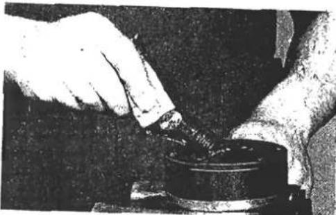

- Fit new circlip supplied in boot kit and ensure it is fully seated in shaft groove.
- Use half grease supplied to pack inboard (rubber boot) side of joint, and fit rubber boot onto joint ensuring smaller end of boot is seated in shaft groove.
- Fit both boot retaining clips as tightly as possible by hand before crimping with pliers.
- Ensure that crimp position of larger clip does not interfere with bolt hole access.
- Pack outer end of joint with remaining grease.
- Fit new end closure plate ensuring bolt holes are aligned.
- Refit driveshaft assembly to vehicle, torque load? all driveshaft socket head bolts to 80 Nm (8.3 kgr.m 60 lbf.ft.).
ENGINE
SECTION EA - 907/912/910 inc. FEDERAL
| Operation | Page | |
| General Description | - | 3 |
| Lubrication | EA 1 | 3/4 |
| Engine Tune (NOT Federal Turbo) | EA 2 | 5 |
| Compression Check | EA 3 | 6 |
| Camshaft Covers | EA 4 | 6 |
| Camshafts | EA 5 | 7 to 13 |
| Valve Clearances | EA 6 | 13/14 |
| Toothed Belt Guard | EA 7 | 14 to 17 |
| Camshaft Driving Belt | EA 8 | 17 to 22 |
| Driving Belt Tensioner | EA 9 | 22 |
| Cylinder Head | EA 10 | 23 to 27 |
| Valves | EA 11 | 27 |
| Decarbonise Cylinder Head and Pistons | EA 12 | 27/28 |
| Valve Seat Inserts | EA 13 | 28 to 30 |
| Valve Guides | EA 14 | 30 |
| Crankshaft 'V' Pulley | EA 15 | 30/31 |
| Crankshaft Sprocket | EA 16 | 31 |
| Front Cover & Oil Seal | EA 17 | 31/32 |
| Water Pump | EA 18 | 33/34 |
| Oil Filter | EA 19 | 34/35 |
| Ignition Distributor | EA 20 | 35/36 |
| Oil Pump and Auxiliary Housing | EA 21 | 36 to 39 |
| Inlet Manifold and Carburettors | EA 22 | 39/40 |
| Oil Sump | EA 23 | 40/41 |
| Connecting Rod (Big-End) Bearings | EA 24 | 41 |
| Engine Assembly | EA 25 | 41 to 45 |
| Flywheel and Ring Gear | EA 26 | 45/46 |
| Crankshaft Rear Oil Seal | EA 27 | 46 to 48 |
| Crankshaft | EA 28 | 48 to 53 |
| Pistons, Piston Rings, Connecting Rods & Cylinder Liners | EA 29 | 53 to 56 |
| Connection of Oil Cooler Thermostat (Turbo) | EA 30 | 57 |
| Lubrication System Precautions | EA 31 | 57 |
| Special Tools | EA 32 | 58 |
| Sealants, Adhesives | EA 33 | 59 |

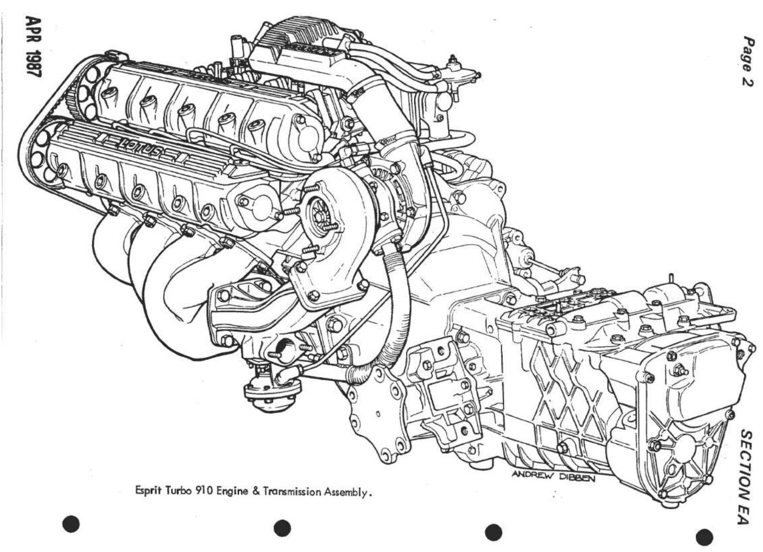
GENERAL DESCRIPTION
The engine which is inclined at 45° is a die-cast all alloy 4 cylinder, with wet cylinder liners and twin overhead camshaft in a cross flow cylinder head.
Pent roof combustion chambers are used with 4 valves (two inlet and two exhaust) having seprate ports, per cylinder. The valves have replaceable guides and seat inserts and are at an inclusive angle of 38° . They are operated by the camshafts acting directly on the cam followers (tappets), the camshafts being driven at half engine speed by a toothed belt. The camshafts end float is taken by a thrust washer at the rear end of each shaft. The toothed driving belt also drives the auxiliary shaft, this in turn driving the oil pump and ignition distributor.
The crankshaft, of cast iron construction and dynamically balanced, runs in 5 steel-backed leaded bronze lined main bearings, end float being controlled by split thrust washers located in the cylinder block on either side of the rear main bearing.
The connecting rods of 'l' section forgings have steel backed bronze little end bushes and steel-backed leaded bronze lined big-end bearings, the big-end bearing caps being located by dowels and retained by bolts. Solid skirt aluminium alloy pistons with two compression and one oil control ring, situated above the gudgeon pin, are used. The gudgeon pins are retained in position by circlips installed in grooves at each end of the gudgeon pin bore.
A cast iron flywheel incorporating a steel ring driving gear for the starter, is located on the crankshaft flange and retained by two dowels and six bolts fitted without lockwashers.
EA.1.-LUBRICATION
General
The lubrication system is of the forced feed type, the oil being circulated by a mechanically driven oil pump. The pump, of the eccentric bi-rotor type which incorporates a non-adjustable plunger type relief valve, is driven by an auxiliary shaft this being contained in the auxiliary housing bolted to the right-hand side of the cylinder block.
Oil is drawn from the sump up a pick-up pipe and into the pump. When the relief valve opens, oil is passed back into the inlet side of pump. From the pump the pressurised oil flows through the oil cooler and full-flow filter to the oil gallery. The oil gallery passes along the right-hand side of the engine, from where oil is taken to feed the crankshaft main bearings and through drillings in the webs of the crankshaft, to the big-end bearings. The oil gallery also takes oil forward to the auxiliary shaft, then subsequently to the camshaft bearings and valve gear. Lubrication of the little end bushes, the gudgeon pins and the non-thrust sides of the cylinder liners is by oil mist.
An oil gallery cover opposite fourth main bearing provides take offs for the oil pressure gauge, turbocharger oil feed and low temperature switch (H.C.I.)
On dry sump Turbo Esprit models a separate belt driven oil pump assembly is used, fixed to the right hand side of the main bearing panel.
The assembly consists of two scavenge pumps and a pressure pump all mounted on a common axis and supported by the scavenge manifold.
The two scavenge pumps draw oil out from the sump via the scavenge manifold, one pump drawing from ducts 1 and 3, the other from ducts 2 and 4. The oil/air mixture is pumped through the oil cooler and into the oil tank oil/air separator. The pressure pump draws oil from the tank and feeds it via a cylinder block passage into the auxiliary housing. A pressure relief valve is incorporated into the scavenge manifold and bleeds oil back into the inlet side of the pump on opening.
The auxiliary housing passageways are modified to direct the oil into the oil filter, (by-passing the pump housing) and thence into the oil gallery.
All Esprit models (except early Series 1) use a 'cross drilled' crankshaft to enable plain lower main bearing shells to be fitted and increase load capacity.
Oil Level
NOT Dry Sump Turbo: Before checking oil level, allow a full five minutes for oil to return to sump. The correct oil level is to the upper mark on the dipstick with the car on a level surface. Add oil if necessary through the filler neck on the inlet camshaft cover. Do NOT overfill. Replace filler cap securely.
The engine oil should be changed and a new filter fitted at the recommended service intervals. Sump capacity is listed in TECHNICAL DATA, and should be drained when the oil is warm and impurities are held in suspension.
Dry Sump Turbo: Check the oil level in the tank at the right hand side of the engine bay WITHIN TWO MINUTES of switching off. Oil will drain back from the tank into the sump when left standing and if the level is checked before the scavenge pumps have returned this oil to the tank, overfilling will result.
The oil should be changed and a new filter fitted at the recommended service intervals. The tank drain plug is located in the right hand rear wheel arch reached after removal of the road wheel. Drain the tank when the oil is warm and impurities are held in suspension. Fill the tank with new oil to the top mark on the dipstick and run the engine for 2 - 3 minutes at 1500 rpm. Switch off and check level within 2 minutes, topping up if necessary.
Oil Filter
A full flow filter of the 'throw-away' canister type, incorporating an anti-drain back valve, is screwed onto the rear of the auxiliary housing.
EA.2.- ENGINE TUNE (NOT Federal Turbo)
-
Pull off the sparking plug leads and remove the plugs. Check the cylinder compressions. Clean the plugs and reset the gaps to the dimensions given in TECHNICAL DATA, or if the electrodes are badly burnt, fit new plugs and re-connect the leads. If contact breaker points are fitted:
-
Remove the ignition distributor and examine the contact-breaker points. Replace the points if badly burnt, or excessive metal transfer is evident. Adjust the points gap to the dimension given in TECHNICAL DATA and refit the distributor.
-
Remove the air cleaner element and clean (or replace if necessary).
-
Disconnect the fuel feed pipe at the carburetters and check the fuel flow. Fuel pressure on Turbo engines = 4.5 lb/in 2 above boost pressure.
-
Dellorto Carburetters - Remove float chamber cover. Withdraw the float assembly. Remove all jets and blow them clear with the assistance of an air line. Do NOT use wire as this will enlarge the jet orifice. Remove the needle valve and valve body and blow clean with an air line. Clean the float and float chamber using clean petrol. Replace all jets, needle valve body and needle valve. Using a new gasket, fit to float chamber cover, replace float assembly. Check float setting. Refit float chamber cover.
-
Zenith-Stromberg Carburetters - Remove carburetters from the engine to a clean bench. Release centre-plug from the base of each carburetter. Remove float chambers by releasing the retaining screws and withdrawing in a vertical motion to avoid damage to the float mechanism. Remove float chamber gasket and take out floats. Remove needle valve from float chamber cover. Remove 'O' ring from base centre-plug. Thoroughly wash all removed parts in clean petrol. Refit needle valve into float chamber cover using a new washer. Replace float assembly. Refit float chambers with a new gasket. Fit new 'O' ring to base centre-plug and replace securely. Refit carburetters to engine using new gaskets. Top up damper reservoirs with oil.
-
Re-connect the fuel pipes at the carburetters.
- Check valve timing, toothed belt tension and condition, valve clearances, adjust as necessary.
- Check the ignition timing, adjusting if necessary.
- Adjust the engine slow-running speed and mixture (see TECHNICAL DATA).
EA.3. - COMPRESSION CHECK
- Warm the engine to its normal operating temperature. Switch 'off' the engine and remove all sparking plugs. Note: before removing spark plugs ensure that plug wells are free of any foreign matter. Set throttles to fully open position.
- Using proprietary compression testing equipment, place the gauge in a convenient position to be observed and insert the conical-ended rubber tube in the No.1 sparking plug orifice. The normal compression pressure with an engine that has been 'run-in' correctly is given in TECHNICAL DATA. At altitudes above sea-level, proportionally lower pressures will be obtained. Compression is checked with the starter motor turning the engine at approximately 200 r.p.m. Battery and starter motor must of course, be in good condition.
- Test the remaining cylinders in a similar manner.
- Replace sparking plugs and re-connect the sparking plug leads.
Three different types of camshaft cover have been used:
- All 907 engines, and naturally aspirated 912 engines prior to 1986, use a 'saddle' type cover with a curved joint face. When refitting this type of cover, it is essential to use Silastic RTV 732 on the joint face of both housing and cover together with a new gasket. Do not overtighten the fixings (See Torque loadings) On some models it may be necessary to place the bolts into the cover before fitting to the engine.
- Turbo 910 engines prior to mid '86 and early '86 M.Y. Excel engines, use flat type cam covers with a three eared filler cap at the front of the inlet cover. Use Hylomar if necessary to retain the gasket whilst fitting. tighten the three slot head retaining nuts with their rubber washers.
- U.S.A. Turbo H.C.I. and other engine variants at later dates, use covers similar to (2) but with the oil filler at the rear of the inlet cover. the gaskets on these engines are retained by spirol pins and the covers by socket head screws and 'O' rings.
EA.5.- CAMSHAFTS
To Remove
- Remove upper section of belt guard(Section EA.7.)(front engined cars only)
- Remove the camshaft covers (Section EA.4.)
- Check all valve clearances (Section EA.6.) noting any which require adjustment.
Remove the timing belt (Section EA.8.) On engines equipped with air - injection, remove the air injection rail from the cylinder head.
- Insert small bar magnets across each of two cam followers, to hold the cam followers in their respective bores. Note: Use magnets only for removal.

Fig. 1 - View showing cam followers held by magnets
- Remove the ten nuts and washers (release the nuts diagonally inwards from the outside) securing the camshaft housing. Care MUST be taken to avoid dropping any nuts or washers down the inside front of the camshaft housing. Remove the housing and discard the gasket. (if fitted).
On Turbo engines, it is necessary to remove the socket head access plugs and then to use 'Torx' socket T000T0443 on the cam housing bolts.
- Repeat the process for the other housing. On front engined cars, release the cooling system header tank before removing the exhaust camshaft housing.
On engines equipped with an air pump, remove the air pump belt guard and belt before removing the exhaust camshaft housing.
- Remove the magnets and release cam followers from their locations. Place them in their respective fitting positions, noting that the cam follower shims are almost always 'stuck' to the underside of the cam follower. If they are not, then they will be 'stuck' to the top of the valve stems. Keep the shim with its respective cam follower.

Fig. 2 - Camshaft housing, cam followers & shims
SECTION EA
- Hold the camshaft sprocket in a vice having fibre protected jaws, and support the camshaft with the other hand.
On engines equipped with an air pump, release the nut, and pull of the 'V' pulley with hub, from the rear end of the camshaft.
Remove the two bolts and washers which secure the rear cover to the housing, and remove cover with its 'O' ring. Release the thrust washer retaining bolt and washer, or 'V' pulley adaptor spindle, and remove thrust washer. Remove bolt and washers securing the toothed sprocket to the camshaft.
Fig. 4 - Camshaft thrust washer & 'O' ring

-
Remove the assembly from the vice, and pull off the camshaft sprocket.
-
Remove the toothed belt snubber (where fitted) from the front of the inlet camshaft housing, by releasing the two M8 nuts, noting the eccentric sleeve fitted on the lower stud.
-
With the aid of a two-legged puller, attached to the rear of the camshaft housing, screw in the centre bolt to push out the camshaft towards the front of housing, together with its oil seal.
-
Repeat the process for the other camshaft and sprocket.

Fig. 5 - Releasing the camshaft
To Replace
- Smear a little graphite grease on the bearing surfaces of the camshaft housing, insert camshaft into its housing from the front and fit a new front oil seal.
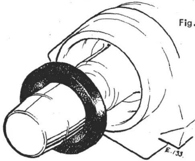
Fig. 6 - Using Tool '72A' to align camshaft oil seal
Fig. 7 - Using Tool '10A' to insert camshaft oil seal

Fig. 8 - Camshaft oil seal fitted
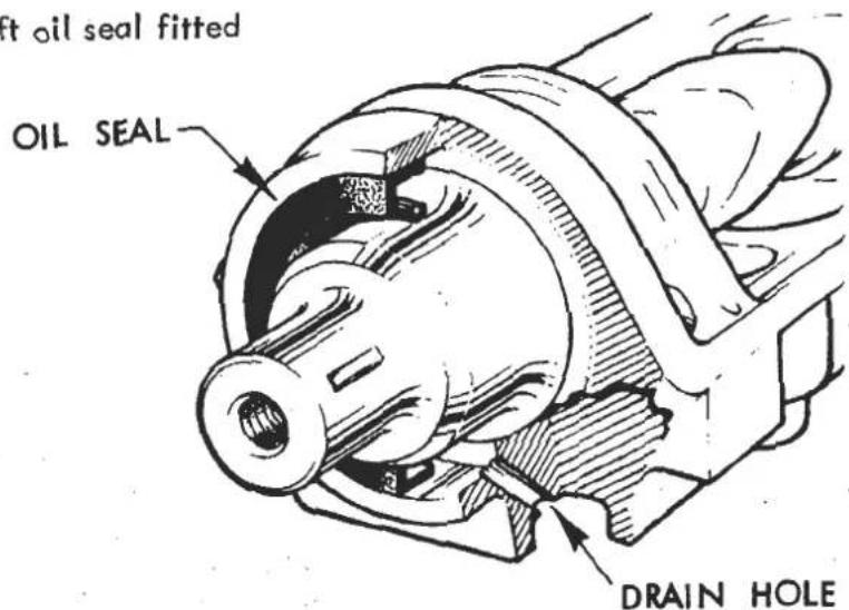
Ensure oil seal is flush with outer face of housing. If seal is fitted to the shoulder inside housing the oil drain hole would be blocked.
- Refit the toothed belt snubber (where fitted) loosley onto inlet camshaft housing, with the eccentric sleeve fitted on the lower stud, and 'Loctite' applied to the nut threads.
- If it has been removed, refit the woodruff key to the front end of the camshaft, and replace camshaft sprocket together with its large plain washer spring washer and retaining bolt. It is ESSENTIAL that the sprockets are fitted the correct way round on each camshaft, i.e. "IN-coloured dot" facing forward on inlet camshaft and "EX-coloured dot" facing forward on exhaust camshaft. See 'TECHNICAL DATA' for correct specification.
- On engines without air pump: fit the selective thrust washer with its retaining bolt, and spring washer, ensuring that it is located on the dowel protruding from the rear end of the camshaft. Hold the camshaft sprocket in the vice (fig.3.). Tighten thrust washer and sprocket retaining bolt to specified loading (see TECHNICAL DATA). Replace rear cover with new 'O'ring, tightening the bolts to their specified torque loading. Check the Camshaft end-float (see TECHNICAL DATA). If the end-float is outside this tolerance, replace the selective thrust washer.
- On engines equipped with an air pump: apply Permabond A138 thread locking compound to the threads of the 'V' pulley adaptor spindle, and screw into the rear of the camshaft securely. Fit the selective thrust washer over its locating dowel, and fit the rear seal housing using a new 'O' ring and oil seal. Apply Silastic RTV 732 into the inside of the 'V' pulley hub, and fit onto the adaptor spindle, ensuring that the dowel engages into the hub correctly. Fit the 'V' pulley onto the hub with the drive line inset towards the engine, fit the M8 washer and self locking nut and torque tighten (see TECHNICAL DATA). Check the camshaft end float - 0.03 - 0.20 mm (0.001 - 0.008 in.). If outside of tolerance, replace selective thrust washer.
Fit the four washers and setscrews securing the 'V' pulley to the pulley hub and tighten.
- Replace cam follower shims onto the ends of the valve stems, these being greased (with graphogen grease) on the valve stem side. Replace the cam followers into their respective bores in the camshaft housing, after an application of graphogen grease.
- In order to avoid damaging the valves when the camshaft housings are replaced, it is ESSENTIAL that the crankshaft is turned BACK approximately 90° from its TDC position, to bring the pistons half way down the cylinders. Do not turn the crankshaft more than 90° back as this may also cause the valves to be damaged.
- On engines up to engine number 11276, using a new gasket, which is DRY and kept FREE OF OIL, replace the camshaft housing with its securing washers and nuts. Tighten the nuts to their specified loadings diagonally outwards from the centre.
On engines from engine number 11276, and earlier engines if fitted with the later camshaft housing with a recess machined around the oil feed for an 'O' ring:
Seal between the cylinder head and cam housing with Loctite 504 gasket eliminator and an 'O' ring fitted over the roll pin dowel. Before applying new gasket eliminator ensure all old gasket eliminator is removed from the mating surfaces of the cylinder head and cam housing. Take care not to scratch sealing surfaces - use a blunt scraper such as the flat end of a steel rule. Degrease and clean the mating surfaces using methylated spirit or similar. Lay a thin continuous bead of gasket eliminator (approx 1/16 to 3/32 in. wide) in the middle of the sealing surface on the cam housing, following the outer surface around the stud holes. Fit 'O' ring on cylinder head dowel and carefully place cam housing on cylinder head studs and secure with washers and nuts. Tighten the nuts to the specified torque loading diagonally outwards from the centre.
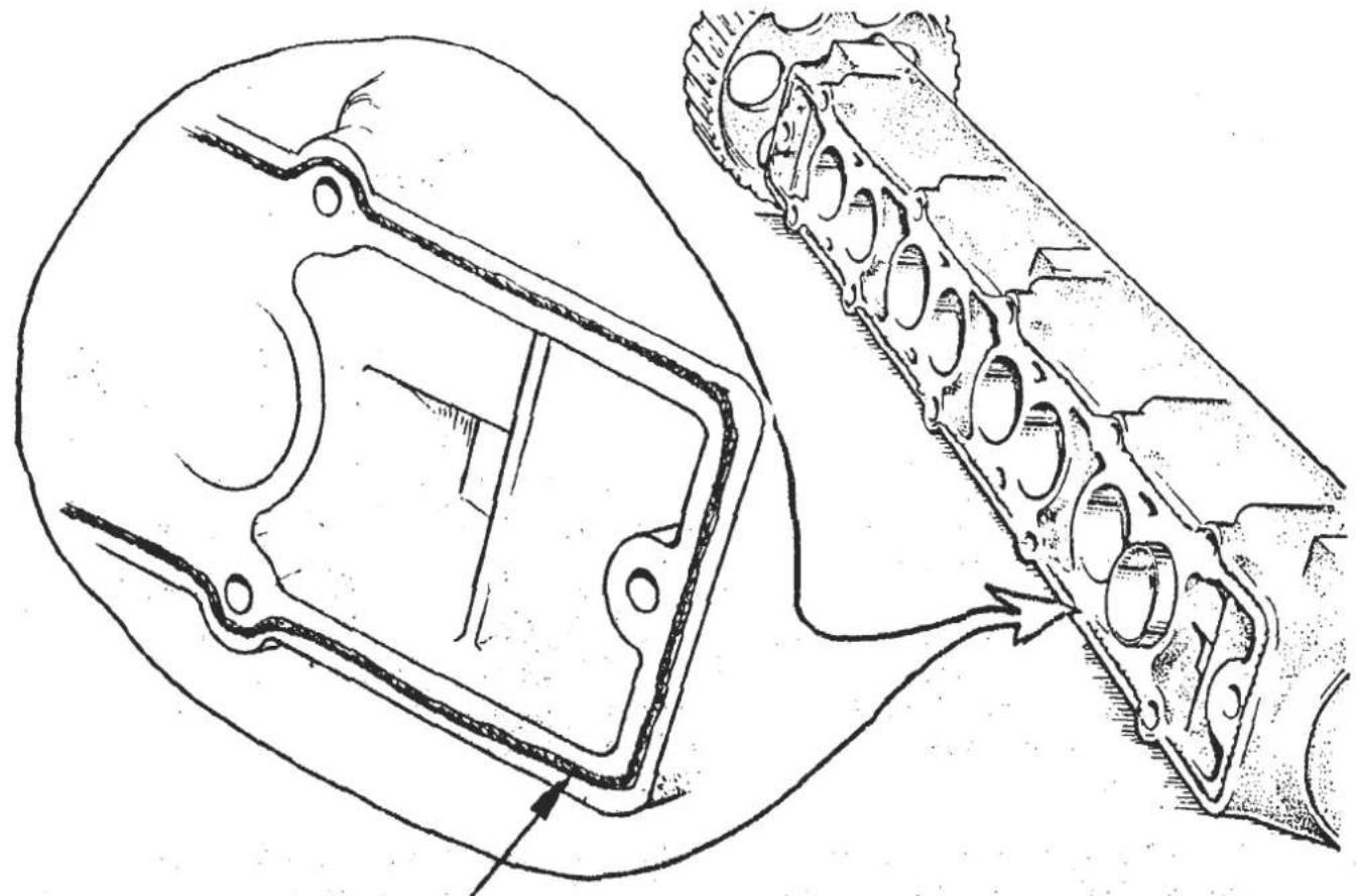
Continuos bead of Loctite 504 Gasket Eliminator.
- Refit the toothed belt snubber (where fitted) loosley onto inlet camshaft housing, with the eccentric sleeve fitted on the lower stud, and 'Loctite' applied to the nut threads.
- If it has been removed, refit the woodruff key to the front end of the camshaft, and replace camshaft sprocket together with its large plain washer spring washer and retaining bolt. It is ESSENTIAL that the sprockets are fitted the correct way round on each camshaft, i.e. "IN-coloured dot" facing forward on inlet camshaft and "EX-coloured dot" facing forward on exhaust camshaft. See 'TECHNICAL DATA' for correct specification.
- On engines without air pump: fit the selective thrust washer with its retaining bolt, and spring washer, ensuring that it is located on the dowel protruding from the rear end of the camshaft. Hold the camshaft sprocket in the vice (fig.3.). Tighten thrust washer and sprocket retaining bolt to specified loading (see TECHNICAL DATA). Replace rear cover with new 'O'ring, tightening the bolts to their specified torque loading. Check the Camshaft end-float (see TECHNICAL DATA). If the end-float is outside this tolerance, replace the selective thrust washer.
- On engines equipped with an air pump: apply Permabond A138 thread locking compound to the threads of the 'V' pulley adaptor spindle, and screw into the rear of the camshaft securely. Fit the selective thrust washer over its locating dowel, and fit the rear seal housing using a new 'O' ring and oil seal. Apply Silastic RTV 732 into the inside of the 'V' pulley hub, and fit onto the adaptor spindle, ensuring that the dowel engages into the hub correctly. Fit the 'V' pulley onto the hub with the drive line inset towards the engine, fit the M8 washer and self locking nut and torque tighten (see TECHNICAL DATA). Check the camshaft end float - 0.03 - 0.20 mm (0.001 - 0.008 in.). If outside of tolerance, replace selective thrust washer.
Fit the four washers and setscrews securing the 'V' pulley to the pulley hub and tighten.
- Replace cam follower shims onto the ends of the valve stems, these being greased (with graphogen grease) on the valve stem side. Replace the cam followers into their respective bores in the camshaft housing, after an application of graphogen grease.
- In order to avoid damaging the valves when the camshaft housings are replaced, it is ESSENTIAL that the crankshaft is turned BACK approximately 90° from its TDC position, to bring the pistons half way down the cylinders. Do not turn the crankshaft more than 90° back as this may also cause the valves to be damaged.
- On engines up to engine number 11276, using a new gasket, which is DRY and kept FREE OF OIL, replace the camshaft housing with its securing washers and nuts. Tighten the nuts to their specified loadings diagonally outwards from the centre.
On engines from engine number 11276, and earlier engines if fitted with the later camshaft housing with a recess machined around the oil feed for an 'O' ring:
Seal between the cylinder head and cam housing with Loctite 504 gasket eliminator and an 'O' ring fitted over the roll pin dowel. Before applying new gasket eliminator ensure all old gasket eliminator is removed from the mating surfaces of the cylinder head and cam housing. Take care not to scratch sealing surfaces - use a blunt scraper such as the flat end of a steel rule. Degrease and clean the mating surfaces using methylated spirit or similar. Lay a thin continuous bead of gasket eliminator (approx 1/16 to 3/32 in. wide) in the middle of the sealing surface on the cam housing, following the outer surface around the stud holes. Fit 'O' ring on cylinder head dowel and carefully place cam housing on cylinder head studs and secure with washers and nuts. Tighten the nuts to the specified torque loading diagonally outwards from the centre.

Continuos bead of Loctite 504 Gasket Eliminator.
- Check valve clearances and adjust if necessary (Section EA.6.)
- Replace camshaft covers (Section EA.4.)
- Re-align timing marks on the camshaft sprockets (Fig. 13)
- Turn the crankshaft back to TDC, and the timing sprocket to align the rotor arm with the previously made reference mark.
- Fit the toothed belt onto the sprocket with the shafts in this position. Pull the belt sufficiently to force the pulley wheel towards the tensioner body. Remove the locking pin and release pressure on the belt. Re-check all the relative sprocket positions. Check toothed belt tension (Section EA.8.) Check ignition timing and adjust if necessary.
- Adjust the inlet pulley snubber (where fitted) for a clearance of 0.50 - 0.75 mm (0.020 - 0.030 in.) between the back of the toothed belt and the snubber bracket. Tighten the securing nuts via the pulley holes to 2.2 - 2.5 kg.m. (15 - 18 lbs.ft.).
- Replace 'V' belts and belt guard (Section EA.7.)
EA.6.-VALVE CLEARANCES
To Check
- Remove both camshaft covers (Section EA.4.)
- Turn engine until heel of camshaft is on the cam follower (of the valve to be checked). Using a feeler gauge, determine the clearance between the cam

Fig. 9 - Checking cam follower clearances.
follower and the camshaft heel. The correct clearance is given in TECHNICAL DATA.
- Check all valve clearances, noting any which require adjustment.
To Adjust
- Remove the camshafts intact in their housings. (refer to Section EA.5.)
-
Remove each adjusting shim where the clearance requires adjustment. Substitute a shim giving the correct clearance, which has been greased on its face abuting the valve stem. ONLY use ONE shim to each valve. NOTE: A Thinner shim will increase the valve clearance, whereas a thicker shim will decrease the clearance.
-
Replace the camshafts(Section EA.5.) after adjustment and recheck the clearance. If the clearance is still incorrect, then the whole of the above procedure MUST be carried out again.
NOTE: Do NOT turn the camshafts with No.1 piston at T.D.C., as this will cause the valves to be bent. Turn the crankshaft back through 90° to bring the pistons half-way down the cylinders. Do NOT turn the crankshaft BEYOND 90° back, as this will also cause the valves to be bent whilst the camshaft driving belt is off.
If, on the later type of camshaft housings (with 'O' ring and no gasket) the valve clearances are to be verified before application of Loctite 504 gasket eliminator, allow 0.0015 in. for this thickness.
EA.7. - TOOTHED BELT GUARD (front engined cars - early type)
To Remove
Upper Section:
- Release the bolt, plain and spring washer on RH side.
- Release bolt, plain and spring washer on inner of LH side, securing the guard to its mounting bracket.
- Release nyloc nut and plain washer in centre of section, taking care NOT to misplace the distance piece between guard and engine when removing the guard.

Page 16
SECTION EA
SECTION EA
- Remove bolt on inlet camshaft cover, securing the belt guard bracket to the engine, and remove upper section.
Lower Section
- Remove the air duct from between the engine and the radiator (see Section 'K').
- Remove the top section of the guard.
- Remove the alternator drive belt and if fitted, the air conditioning compressor pump belt, and power-assisted steering pump drive belt.
- Release the bolt securing the guard bracket to the thermostat housing.
- Remove the nyloc nuts and plain washers from both sides at the bottom of the guard, taking care NOT to misplace the distance pieces (one on each stud).
To Replace
- Replacement of both upper and lower sections of the belt guard is a reversal of the removal instructions, NOT forgetting the distance pieces in their correct locations.
EA.8.- CAMSHAFT DRIVING BELT (TOOTHED BELT)
Prior to '86 M.Y. all engines use a trapezoidal (nearly square) tooth profile belt with originally, a manually adjusted eccentric belt tensioner, and later a semi-automatic spring loaded tensioner. 1986 M.Y. Excel and U.S.A. Turbo H.C.I. models and other engines at a later date use an H.T.D. (High Torque Drive) cam belt and pulley set, having a rounded tooth profile. A manually adjusted eccentric belt tensioner is generally used with the H.T.D. belt, and no snubbers are necessary.
TO ADJUST
Do NOT attempt to tension a hot engine. Only carry out, this adjustment at an engine (ambient) temperature of between 15° - 25°C.
Use cantilevered Burroughs Gauge T000G0025J between the auxiliary and inlet camshaft pulleys in the following manner, removing the belt guard upper section and such ancillary equipment as may be necessary to gain access.
Fully extend the hook by pushing the handle completely down before inserting the belt between the nose piece and hook, ensuring that the hook is between the belt teeth. Release the handle with a rapid action. A slow release will result in a HIGH reading owing to the small amount of internal friction present stopping the hook from fully returning. Note the indicator dial reading. Repeat action several times to 'get the feel'.
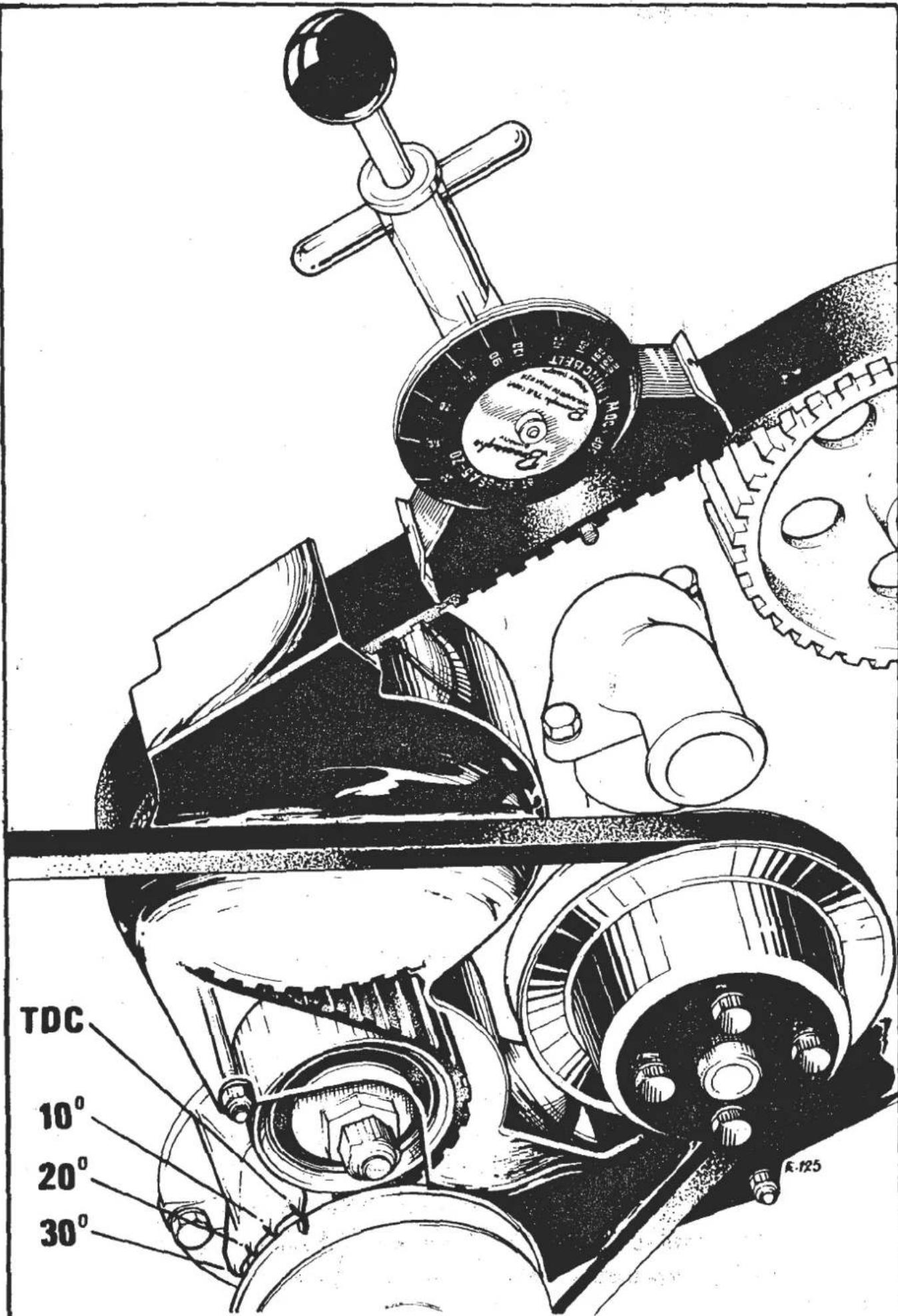
Fig. 11 - Engine timing marks & Burrouahs gauge in position
Page 20
SECTION EA


Fig. 13 - Sprocket positions with Number 1 cylinder at TDC.
Take a further two readings at intervals of 120 crankshaft degrees, turning only in normal operating direction.
The correct belt tension setting for all engines where NO air pump is driven off the back of the belt is: 90 - 95 units, cold. (120 - 125 units hot). If the reading falls outside this range, adjust the tension as follows with No. 1 piston at TDC after rotating the crankshaft a minimum of one turn clockwise
Manual tensioner: Slacken the nut securing the pulley, and by means of the hexagon on the front of the pulley, adjust the tension of the belt. Tighten the pulley securing nut. After adjustment, re-check the tension with the Burroughs gauge.
Semi-automatic tensioner: Where no air pump is driven off the back of the toothed belt, slacken the locknut, and screw the spring seat (adjusting screw) in or out to obtain the correct Burroughs gauge reading. Tighten the locknut.
On Federal engines where an air pump is driven off the back of the toothed belt, first slacken off the air pump fixings. Screw the spring seat (adjusting screw) clockwise until only one or two threads are showing above the locknut, and tighten locknut. Tension the air pump to 5.5 kg.m (40 lbs.ft.) using special tool part number T000T0320A and a dial torque wrench. Entirely release load on air pump and then re-torque to a final tension of 2.8 kg.m (20 lbs.ft.) and tighten all air pump mountings in that position.
To Remove
-
Remove both upper and lower sections of the belt guard (Section EA.7.) Remove all 'V' belts.
-
Set the engine in the timing position with No. 1 piston at T.D.C. Align the timing mark on the crankshaft 'V' pulley with the mark on the front cover. At this point the marks on the camshaft sprockets should also be aligned with each other. Remove the crankshaft 'V' pulley. (Section EA.15.)
-
Mark the position of the auxiliary shaft sprocket against the belt snubber, (or similar) as with the belt removed, the shaft will almost certainly turn, thus losing the correct ignition timing.
-
a). Release the belt tension by releasing the securing nut on manual tensioners.
b). On semi-automatic tensioners, release the alternator and adjusting strap if necessary to gain access to the tensioner adjusting screw.
c). Slacken off locknut and release adjusting screw (spring seat) by turning it anti-clockwise until the adjusting screw is protruding a MAXIMUM of 12 mm ( 1/2 in) from the tensioner housing.

d). Force idler towards tensioner body (merely tension timing belt by hand) until groove on piston aligns with locking pin hole in housing, and insert a 4mm diameter pin. This locking pin hole may be located on the lower side of the piston bore, or on the upper side, obscured by the upper fixing bolt/nut washer, which must therefore be removed. The pin is inserted to prevent the springs pushing the assembly apart and consequently losing all the parts.
IMPORTANT: The locking pin must be fitted to the tensioner housing every time the toothed belt is being removed or slackened off. This
also applies to engines where the air pump is driven from the back of the toothed belt.
Do not under any circumstances attempt to remove locking pin from the tensioner assembly, other than when unit is installed on an engine with timing belt in position.
- Remove toothed belt from sprockets.
NOTE: Do NOT turn the camshafts with No.1 piston at T.D.C. as this will cause the valves to be bent. Turn the crankshaft back through 90° to bring the pistons half-way down the cylinders. Do not turn the crankshaft BEYOND 90° back whilst the camshaft driving (toothed) belt is OFF otherwise there is danger of the pistons contacting any valves which may be off their seats.
To Replace
-
Reverse the removal procedure. Before fitting belt, ensure correct position of crankshaft, camshafts and auxiliary shaft sprocket (fig.13).
-
After fitment, adjust belt tension, and check ignition timing. If a new belt has been fitted, run the engine for a minimum of two minutes, switch off and recheck tension.
EA.9. - DRIVING BELT TENSIONER
To Remove
Carry out the procedure detailed in SectionEA.8. for removing the camshaft drive belt, although it will not be necessary to actually remove the belt. Release the bolts or bolt and nut securing the tensioner assembly, making careful note of all the bracket positions and spacer washers. Remove the tensioner.
On some cars (i.e. air conditioned) with two bolts securing the tensioner, it may not be necessary to remove the crankshaft 'V' pulley.
To Replace
Reverse the removal procedure checking the valve timing, ignition timing and belt tension and adjusting as necessary. Adjust the auxiliary pulley snubber for a clearance of 0.4 ± 0.1 mm ( 0.016 ± 0.004 in.) between the pad and toothed belt.
EA.10.-CYLINDER HEAD
To Remove (Naturally Aspirated)
- Disconnect the battery (see Section 'M').
- Drain the cooling system (see Section 'K').
- Remove the air duct from in front of the engine (see Section 'K'). (Elite/Eclat).
- Release the clip securing the air trunking to the airbox and remove airbox outer cover, together with the air cleaner element, after releasing its securing bolts and washers, or fastening clips.
- Remove the complete belt guard (Section EA.7.) (front engined cars).
- Disconnect the water hoses from their connections on the cylinder head and on the inlet manifold.
- Remove the inlet manifold together with the carburetters (Section EA.22).
- Remove the spark plug leads from the plugs and secure out of the way of cylinder head removal.
- Release the exhaust downpipe from the exhaust manifold and remove manifold, (see Section 'S').
- Some engines, fitted with the non air conditioning type water pump may require removal of the water pump before the cylinder head may be lifted.
- Remove the cam covers and check the valve clearances (Section EA.6.) noting any which require adjustment.
- Remove the camshaft housings with cams (Section EA.5.)
- Release the cylinder head nuts evenly and progressively, working diagonally inwards from outside. Remove the nuts with their washers. Remove the
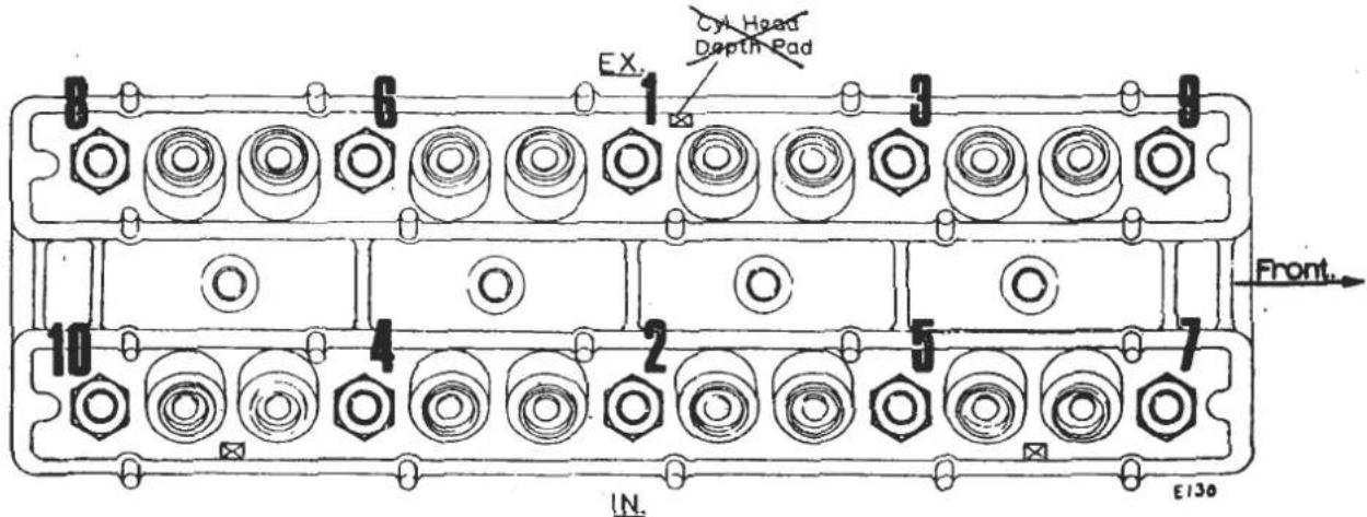
- Cylinder head nut tightening/releasing sequence

907/912 Cylinder Head & Cam Housings.
cylinder head and retain the head gasket on 912 engines for reference on rebuild. Do NOT lay the cylinder head face down on the bench without first covering the bench with a protective material otherwise the mating face of the cylinder head could be damaged.
- Do NOT turn the engine without FIRST fitting cylinder liner clamps otherwise the liners could be pushed from their locations.

To Remove (Esprit Turbo)
NOTE: On Turbo models cylinder head removal is more easily carried out with the engine removed from the car (Section EA.25.)
- Remove the inlet manifold and carburetters assembly (See Section EA.22.)
- Remove the oil feed and drain pipes from the turbocharger, and remove the exhaust manifold complete with wastegate and turbo. On air injection engines, remove the air pump 'V' belt guard, and air injection rail.
- Remove the cam covers and check the valve clearances (Section EA.6.) noting any which require adjustment.
- Remove the camshaft housings with cams (Section EA.5.)
- Release the cylinder head nuts evenly and progressively, working diagonally inwards from outside. Remove the nuts with their washers. Remove the cylinder head with its gasket. Do NOT lay the cylinder
head face down on the bench without first covering the bench with a protective material, otherwise the mating face of the cylinder head could be damaged.
Do NOT turn the engine without first fitting cylinder liner clamps, otherwise the liners could be pushed from their locations.
To Replace
- Remove the cylinder liner clamps. Thoroughly clean both the cylinder block and cylinder head mating faces (use Trichlorethelene or petrol).
- Fit new cylinder head gasket. The gasket is fitted with 'Wellseal' applied around the periphery of both sides of the oil pressure hole.
912 Head Gasket Selection
When replacing the head gasket on a 9.44:1 CR 912 engine (ie: NOT H.C.), note the type of gasket fitted, (ie. count laminations) or the part number stamped thereon, and replace with the same type.
If the cylinder liners, crankshaft or reciprocating components have been changed, the piston standout above the liner flange must be measured. If the standout is measured at right angles to the gudgeon pin, the height on both sides of the piston must be measured and then averaged Select a gasket from the following table based on the highest standout.
| Standout | Description | Part No |
| Less than 0.014 in. | No extra laminations | A907E0026 |
| 0.014 - 0.023 in. | One extra lamination | B911E1291 |
| 0.023 - 0.032 in. | Two extra laminations | B911E1292 |
- Fit the cylinder head assembly, plain washers and nuts. Tighten all nuts in stages to the specified torque loading working diagonally outward from the centre.
- Replace both camshaft carrier housings. Check valve clearances. (Section EA.5. and EA.6.).
- Replace camshaft drive (toothed) belt, spark plug leads and set static ignition timing (Section EA.8.)
- Refit ancillaries in reverse order to dissassembly.
SECTION EA
- Close coolant drain tap on radiator and refill the cooling system, with a inhibitor/anti freeze solution.
- Check engine oil, start engine and allow to reach its normal operating temperature. Adjust slow running speed and mixture, and ignition timing. Check for oil and coolant leaks while engine is running. Thoroughly check fuel system for leaks and security of joints.
EA.11.-VALVES
To Remove
- Remove the cylinder head (Section EA.10.)
- Using a suitable valve spring compressor, compress the valve springs and extract the split collets. Release the valve spring compressor, and remove the valve spring retainer, valve springs and spring seat from each valve. Remove the valve.
- Repeat the process for the remaining valves. Label each valve with its location.
To Replace
- Check the valve seats for condition, re-cutting as necessary, and check condition of valve guides. Grind in all valves.
- Lightly lubricate the stem of the valve and insert into its guide.
- Fit spring seat, valve springs, spring retainer. Place the valve spring compressor in position and compress the valve springs sufficiently to fit the split collets. Release the valve spring compressor.
- Repeat the process for the remaining valves.
- Replace the cylinder head followed by the camshaft housings. Re-check the valve clearances.
- Replace ancillaries.
EA.12.-DECARBONISE CYLINDER HEAD & PISTONS
To Remove
- Remove cylinder head to a clean covered bench. (Section EA.10.)
-
Remove the valves (Section EA.11.)
-
Remove all carbon deposits from the cylinder head combustion chamber faces, inlet and exhaust ports, piston crowns and valve heads. A ring of carbon should be left around the periphery of each piston crown. The TOP of the cylinder liners should NOT be touched.
-
Clean each valve thoroughly and carefully examine for pitting. Valves in a pitted condition should be refaced with a suitable grinder or new valves should be fitted. If the valve seats show any signs of pitting, or unevenness, they should be trued by the use of service cutting tools. When using a cutting tool take care to remove only as much metal as is necessary to ensure a true surface. The removal of too much metal could cause difficulty in achieving the required valve clearance.
-
When grinding a valve onto its seating the valve should be smeared lightly with 'fine' or 'medium' carborundum paste and then lapped in with a suction type grinder after oiling the valve stem. Avoid the use of excessive quantities of grinding paste and ENSURE that it remains in the region of the valve seating only. A light coil spring placed under the head of the valve will assist considerably in the process of grinding. The valve should be ground to its seat with a semi-rotary motion and occasionally allowed to rise by the pressure of the light coil spring. This action assists in speeding the grinding operation until a dull, even, matt finish, free from any blemishes is achieved on the valve seat and valve face. On completion, the valve seats, guides and parts, should be cleaned with petrol then blown dry and clean with compressed air. The valves should be washed in petrol and all traces of grinding paste removed. Ensure that no grinding paste has entered the valve guides.
-
Lightly oil the valve stems, and re-assemble the valves to cylinder head.
-
Refit cylinder head, camshaft housings not forgetting to check the valve clearances, camshaft covers, inlet and exhaust manifolds, carburetters, etc.,
EA.13.-VALVE SEAT INSERTS
To Remove
- Remove the cylinder head and dismantle as for decarbonising (Section EA.12.)
- Remove the valve seat inserts by milling through, or almost through (dependant upon the skill of the operator), the edge of the insert, whereupon the seat should
collapse. In the case of a stubborn seat, it is permissible after milling to start the seat on its way to removal by inserting a suitable drift through the appropriate port and gently tapping the seat from its recess. Ensure that the recess in the cylinder head is ENTIRELY FREE OF FOREIGN MATTER, otherwise the new insert will NOT seat fully in the recess.
To Replace
- Check the combustion chamber adjacent to the respective seat for a '1', '2', or '5' stamping, (or alternatively 'C', 'D', or 'E') this indicating that an oversize valve seat was fitted in production (0.001 in, 0.002 in and 0.005 in respectively).

Fig.18 - Location of valve seat oversize stamping
If this stamping is visible then that size (or larger) seat MUST be used as replacements. The letters 'C', 'D', or 'E' refer to the prefix letters of the respective part numbers.
-
Heat the whole cylinder head to a temperature NOT EXCEEDING 200° C. and freeze the insert with dry ice to a temperature NOT LESS THAN minus 80° C.
-
With the aid of Special Tool (05A or 06A), press the insert into place, ensuring that the seat FACES TOWARDS the combustion chamber. Allow the cylinder head to cool naturally in the air.
-
Re-build and refit the cylinder head.
EA.14.-VALVE GUIDES
Check the valve spring seat adjacent to each guide bore for a '1', '2' or '5' stamping. This refers to the amount of oversize of the guide (.001 in, .002 in, and .005 in, respectively).
If this stamping is visible, then that size or larger guide MUST be used as replacements.

To Remove
- Remove the cylinder head and dismantle as for decarbonising. (Section EA.12.)
- Heat the whole cylinder head to a temperature of between 100/150°C. (212/303°F.). and, with Special Tool (04A), knock the guides out of the head from the combustion chamber side.
To Replace
- Heat the cylinder head to a temperature of between 100/150°C. (212/303°F.).
- Locate a new circlip on the new guide and press the guide into its bore from the top, until the circlip seats completely in its recess. Care must be taken that the guides are NOT driven in further than this point. See TECHNICAL DATA for fitted height.
- Ream the guide AFTER fitting, to the dimension given in TECHNICAL DATA. Recut the valve seat to ensure that it is concentric with the valve stem bore.
- Re-build and refit the cylinder head to the engine.
- Remove all the 'V' belts.
- Remove the set screw, and special washer from the centre of the pulley. Pull off pulley, using a proprietary puller if necessary.

To Replace
- Reverse the removal procedure. Torque retaining screw to 7.6 - 9.3 kg.m. (55 - 60 lbs.ft.). Check all 'V' belt tensions after replacing.
EA.16.- CRANKSHAFT SPROCKET
To Remove
- Remove the belt guard (Section EA.7.) and set the engine in the timing position (Section EA.8.)
- Remove the camshafts driving belt (toothed belt) (Section EA.8.)
- With the aid of Special Tool T000T0170A, pull off the crankshaft toothed pulley followed by the belt guide flange. Tighten the tool bolts finger-tight only. NOTE: On dry sump Turbo models first remove the oil pump drive sprocket.

Fig. 19 - Using Tool T000T0170A to remove crankshaft sprocket
To Replace
- Ensure that the engine has not been turned from the timing position.
- Reverse the removal procedure.
EA.17.-FRONT COVER & OIL SEAL
To Remove
-
Remove the belt guard (Section EA.7.) and set the engine in the timing position (Section EA.8.)
-
Remove the camshafts driving belt (toothed belt) (Section EA.8.).
- Remove the crankshaft sprocket (Section EA.16.).
- Remove the camshafts driving belt tensioner (Section EA.9.).
- Release the set-screws with their plain washers from around the periphery of the cover. Pull off cover and gasket.
- Remove the oil seal from the cover by pushing from its location.
To Replace
- Using a new oil seal, with 'Wellseal' sealing compound applied to its outer diameter, insert into the front cover until flush with the rear face.
- Apply jointing compound to both faces of a new gasket and replace front cover, with the aid of Special Tool T000T0009A. On early engines, ensure that the stud which retains the camshafts driving belt tensioner is centralised in the hole of the front cover. Secure cover with its set-screws and plain washers, tightening the screws to the specified torque loading (see TECHNICAL DATA).
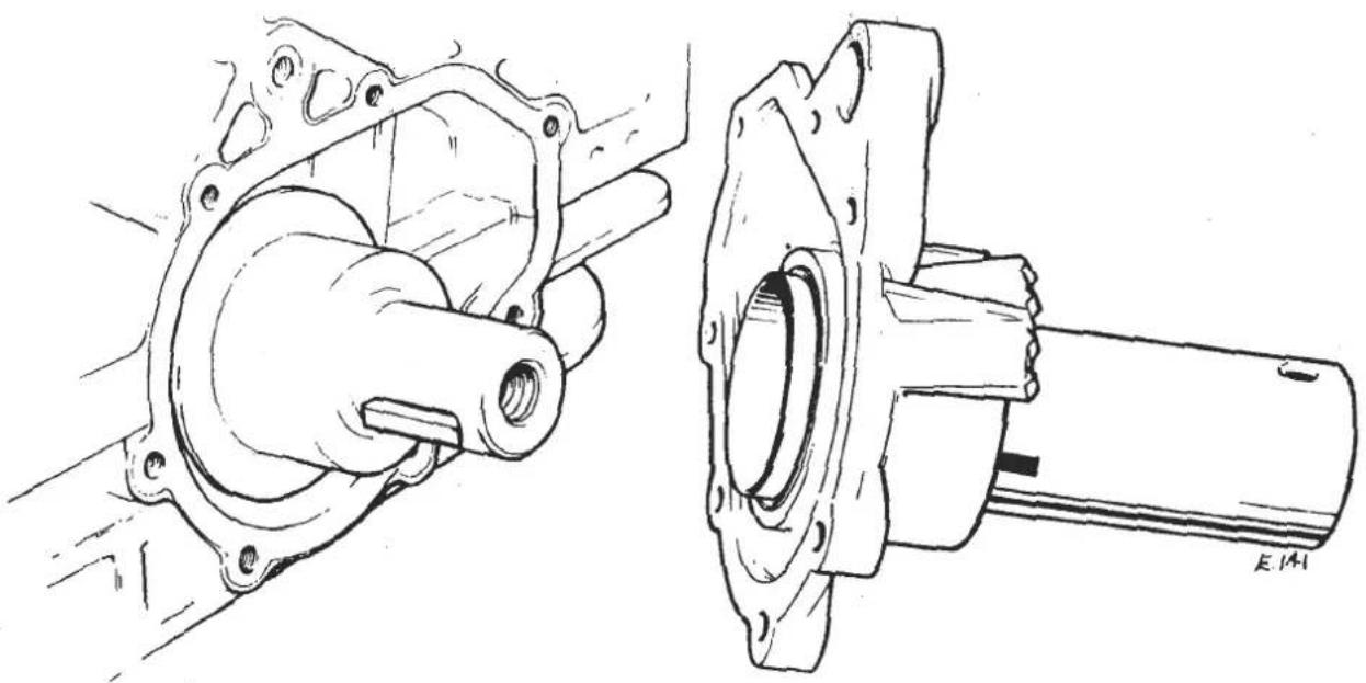
Fig. 20 - Using Tool T000T0009A to locate front cover
- Replace the remainder of the removed parts by reversing the removal procedure.
EA.18.- WATER PUMP
To Remove
- Drain the cooling system.
- Remove the complete belt guard (Section EA.7.) and the water pump 'V' belt.
- Release the clips and remove all hoses from the water pump housing.
- Where power steering is fitted, remove the power steering pump mounting bracket and secure (with hoses attached) clear of water pump.
- Release the water pump fixing bolts, and remove bolts and washers together with the water pump housing and gasket. Discard the gasket.

NOTE: On some engines it may be necessary to first remove the auxiliary shaft pulley, in order to gain access to the water pump retaining bolts. In such cases, take the necessary precautions to ensure that valve and ignition timing are not lost by referring to Section EA.8.
Before discarding the water pump, measure the dimension from pulley mounting face on hub, to pump body mounting face, in order that the new pump may be assembled correctly.
To Replace
- If fitting a new water pump to a 907 engine, press a new pulley hub onto the shaft to achieve the dimension measured in EA.18. Press only on the hub and opposite end of the shaft (NOT impeller). Check impeller/housing clearance is to dimension shown in Fig.21.
- Using a new gasket, to which a suitable jointing compound has been used on both sides, refit the housing assembly to the engine, tightening all bolts to their specified torque loddings (see TECHNICAL DATA).
- Replace all ancillaries.
- Refill the cooling system, and check for water leaks with the engine running.
EXCEL MODELS - 1985 MODEL YEAR ONWARD
On these cars, no gasket is fitted, but Permabond A136 is used in the following manner.
- Clean the joint faces on both water pump and cylinder block.
- Spray both joint faces with Permabond A905 Surface Conditioner (A912E6759)
-
Apply a 3-4 mm wide bead of Permabond A136 (A912E6421) to the water pump joint face as shown in the diagram.
-
Take care when fitting the water pump not to break the bead of Permabond.
Fit the water pump fixing bolts and washers and torque tighten to 0.8 - 1.1 kgf.m. (6 - 8 lbf.ft)
- The system may be refilled with coolant immediately after reconnecting hoses.
Parts Required
Permabond A136 Adhesive
A912E6421
Surface Conditioner A905
A912E6759

EA.19.-OIL FILTER
To Remove
- To remove the filter, use a suitable filter removal tool and turn in an anti-clockwise (towards the cylinder block) direction. Discard the filter. Ensure the oil cooler adaptor is not disturbed during this operation.
To Replace
- Clean the mating face on the oil pump body. Add a small amount of clean engine oil into the filter then, apply a film of engine oil to the new seal (supplied with the new filter) which is in contact with the oil pump body, locate filter on its adaptor and screw on by HAND in a clockwise direction. When the filter 'seats' continue turning the filter for a further two-thirds to three-quarters of a turn to ensure an oil tight joint.

Fig. 22 - View showing oil pump, filter & ignition distributor
Where an oil cooler is fitted, ensure that the adaptor is not disturbed from its seating on the auxiliary housing during this operation.
- Start the engine and check for oil leaks at the filter to oil pump joint, if necessary tightening the filter further to give an oil tight joint.
All '86 Model Year and some late '85 Model Year cars are fitted with engine oil filter B907E 6000 which differs from filter A907E 6000 in the following respects:
i) Provision of 'flats' on canister to aid removal with oil filter spanner.
ii) Slightly shorter canister to provide fitting clearance for spanner.
iii) Revised end plate with less thread protrusion
In order to provide sufficient thread engagement as a result of iii above, the oil filter union extension has been increased in length by 3mm.
a) 1986 USA Turbo H.C.I. models should only be fitted with B907E 6000 due to the restricted access.
b) All other 1986 Model Year cars may be fitted with either 'A' or 'B' prefix filters.
c) ALL CARS PRIOR TO '86 M.Y. MUST BE FITTED WITH FILTER A907E 6000.
Fitment of 'B' filter to these cars may result in insufficient thread engagement with consequent danger of the filter working loose.
In order to avoid any confusion in the U.K. it is recommended that U.K. dealers stock only 'A' prefix filters which are suitable for all cars.
EA.20.-IGNITION DISTRIBUTOR
To Remove
- Turn engine until at the timing position. (Section EA.8.)
- Remove the distributor cap.
- Disconnect the low tension cable (points) or trigger lead connector block (electronic)
- Disconnect the vacuum pipe to distributor (if fitted)
- Mark the position of the distributor body against the oil pump housing, release the nut securing the distributor clamp to the oil pump housing, and withdraw distributor.
Note: Special socket spanner required on 1983 on Federal cars - T000T0503. - Ensure the spring is retained in the dog drive slot.
To Replace
-
Before fitting the distributor, ensure that the contact breaker points (if fitted) are in good condition and correctly adjusted (see Technical Data).
-
Note that the driving dog on the distributor shaft is offset, and that it must be turned to match the offset slot in the auxiliary shaft before fitting. Insert the distributor, ensuring that the drive dogs are fully engaged, align the reference marks made previously on the distributor body and auxiliary housing, and secure the clamp. DO NOT OVERTIGHTEN.
- Reconnect the vacuum pipe, (if fitted) the low tension lead or trigger lead, and the distributor cap. Check the static ignition timing at the coil negative terminal.
- Run the engine and check/adjust the ignition timing as specified in TECHNICAL DATA.
EA.21.-OIL PUMP & AUXILIARY HOUSING
To Remove
- Set the engine to the timing position and remove camshaft driving belt (Section EA.8.)
- Remove the carburetters airbox backplate or plenum chamber (Turbo).
- Remove distributor (Section E A.20.)
- Remove the oil filter, and alternator.
- Where applicable, remove the compressor rear mounting bracket.
- Fully release all the bolts securing the housing to the cylinder block, noting the position of the various bolts (some are longer than others) and remove housing together with its gasket. Discard the gasket.
- With the assembly on a clean bench, remove the auxiliary shaft sprocket by releasing its central retaining bolt and washer.
- Remove the bolts and washers retaining the oil pump body to the auxiliary housing and remove body with its gasket. Take care that the spring in the end of the auxiliary shaft, and the annulus (not fitted in Dry Sump Turbo models) is not misplaced during this operation. Discard the oil pump body gasket.
- Remove the spring from the oil pump end of the auxiliary shaft. Remove the circlip securing the inner rotor of the oil pump to the shaft. Remove the circlip from the forward end of the shaft. Push shaft out of housing from the front end. Using a suitable drift, remove the front oil seal. Dry Sump Turbo models are also fitted with a rear oil seal.
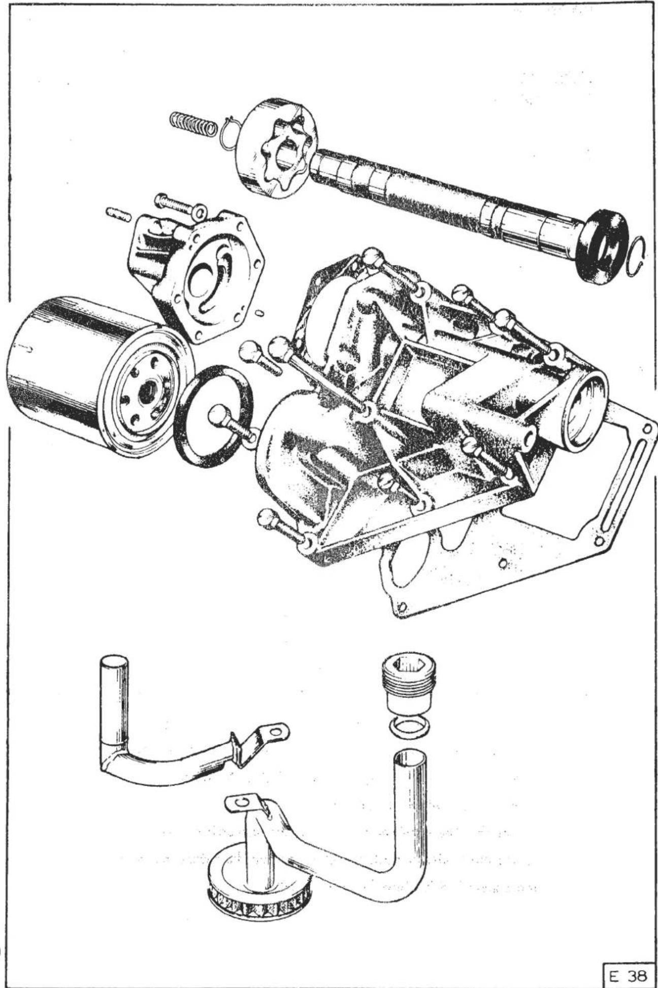
Fig. 23 - Oil pump/auxiliary housing components
To Replace
- Using a new oil seal, press it into its location. The lip of the seal should of course be towards the housing.
- Fit new key to the oil pump end of the shaft and using the new oil pump rotors, fit the inner one to the shaft. Fit a new circlip to secure.
- Push the shaft into the housing from the oil pump end so that the shaft protrudes through the oil seal at the front end. Fit circlip.
-
Insert the ignition distributor shaft loading spring into the oil pump end of the auxiliary shaft. Fit a new oil pump annulus (outer rotor) into the pump body (Except dry sump Turbo). Fit the oil pump to the auxiliary housing using a NEW gasket which is fitted DRY. Tighten all bolts to the specified torque loading (see Technical Data).
-
Using a new gasket to which a suitable compound has been added to both faces, refit the auxiliary housing to the cylinder block. On engines fitted with an 'adaptable' type auxiliary housing with separate alternator bracket (i.e. with air conditioning) note that the mating faces between the alternator mounting bracket and auxiliary housing are not touching, and MUST be sealed with "Silastic." Apply a bead of "Silastic" to either one mating face, enough to form an approximate 0.5mm thick gasket when the parts are fitted.
Ensure that the retaining bolts are replaced in their original locations, and that the spacer is fitted between the alternator bracket and auxiliary housing on the lower front bolt. Tighten bolts to torque loading given in TECHNICAL DATA.
-
Replace the auxiliary shaft sprocket on the shaft using a new key and with the relevant timing mark facing forward (see fig. 13). Apply thread locking compound to the special securing bolt, and fit with special washer, torque tightening to specified figure (see TECHNICAL DATA).
-
Replace the ignition distributor.
-
Ensure that the crankshaft and camshafts are still at the timing position, rotate the auxiliary shaft sprocket to align the reference mark, and replace the camshaft drive belt (Section EA.8.)

Fig. 24 - TDC position of distributor rotor arm
- Replace the low tension cable and the distributor cap. Replace oil filter and the alternator. Replace the carburetters airbox assembly. Re-check ignition timing.
EA.22.-INLET MANIFOLD & CARBURETTORS
To Remove (Naturally Aspirated)
- Drain the cooling system (see Section 'K').
- Remove the airbox outer cover (see Section 'L').
- Disconnect the water hoses from the manifold.
- Disconnect the breather pipe from the flame trap at the rear end of the airbox backplate. Disconnect the throttle and choke cables, and the vacuum pipes.
- Disconnect the fuel feed pipe to the carburettors, and fit plug to main fuel pipe to prevent fuel draining from the tank.
- Release the nuts and washers securing the manifold, and remove manifold.
- Further dismantling of the manifold, such as removing the carburettors, may be carried out as desired on the bench.
To Remove (Esprit Turbo)
- Drain the cooling system.
- Disconnect throttle and choke cables.
- Disconnect fuel pipes from pressure regulator.
- Release water hose(s) from inlet manifold or water rail.
- Release vacuum connections from inlet manifold or vacuum rail.
- Disconnect diffuser from turbocharger and seal turbo compressor outlet immediately.
- Release fuel pressure regulator from plenum chamber. Release evaporative loss hose from front of plenum, and also electrical connections and vacuum pipes as necessary.
- Release heater water transfer pipe from plenum chamber.
- Remove manifold to head nuts and washers and remove complete assembly to bench.
To Replace
- Reverse the removal procedure, but use a new gasket. Tighten all nuts to the specified torque loadings (see TECHNICAL DATA).
EA.23. - OIL SUMP (NOT Dry Sump Turbo)
To Remove
On front engined cars it is necessary to disconnect the downpipes from the manifold, release the engine mountings and raise the engine 2 - 3 inches (5 - 8 cm) to gain sufficient sump to crossmember clearance.
- Using a suitable receptacle, release the drain plug and allow oil to drain from the sump. Remove the dipstick.
- From around the periphery of the sump, remove the setscrews and nuts with their plain washers securing the sump to the main bearing housing. Release the clutch housing to sump bolts, noting any shim washers fitted.
Remove the sump by tilting it slightly towards the exhaustside of the engine in order to clear the oil strainer and pick up pipe assembly.
To Replace
- Thoroughly remove any sludge which may have collected in the sump, BEFORE replacing the sump.
- On 907 engines, use a new gasket with jointing compound applied to both faces. No gasket is used on 912 engines but Perma Bond A 136 (A912E6421) should be used in the following manner. Apply a 1.0 - 1.5 mm bead of Perma Bond to the joint face on both the sump and main bearing housing, with the bead passing to the inside of the fixingholes. Also, on 912 engines, check that the 'O' ring is fitted over the dipstick tube inside the main bearing housing.
On 912 and Wet Sump 910 engines, check underside of the sump by clutch housing fixings for shim marking '000' - no shim, '020' - one shim, '040' - two 0.020" shims. These shims to be fitted between clutch housing and sump.
Fit sump and tighten fixings to their specified torque loadings (see TECHNICAL DATA).
- Refill the engine with the recommended oil.
NOTE: If a new sump is to be fitted on a 912 or Wet Sump 910 engine, carry out the following Sump Alignment Procedure.
i) With the clutch housing fitted to the engine, fit the sump to the main bearing housing, but do not tighten fixings. Pull the sump rearwards, towards the clutch housing, and measure the clearance between sump bosses and clutch housing.
ii) If less than 0.010" torque up sump bolts with sump in rearmost position. If clearance is greater than 0.010", fit shims at the two fixing points as follows.
Clearance
0.010"-0.030"
0.030"-0.050"
Shim
one 0.020"
two 0.020" (0.040")
EA.24. - CONNECTING ROD (BIG-END) BEARINGS (Dry Sump Turbo see Section EA. - 28
To Remove
- Remove the sump. (Section EA.23.)
- Commencing with No.1 (from front end) connecting rod, turn the crankshaft to facilitate removal of cap. Mark cap and rod.
- Release the bolts by two or three turns and tap them to release the cap. Fully release the bolts and remove the cap.
- Remove the upper and lower big-end bearing shells from both the connecting rod and the connecting rod cap.
To Replace
- Replace the upper and lower big-end bearing shells by new parts in their appropriate locations.
- Fit the cap to the connecting rod and tighten the bolts to the torque loading given in TECHNICAL DATA.
- Replace the remaining big-end bearings by repeating the above process.
- Replace the oil sump assembly.
EA.25. - ENGINE ASSEMBLY
The engine and gearbox should be removed as a complete assembly.
To Remove - Front engined cars
- Remove the bonnet (see Section 'B').
-
Drain the cooling system (see Section 'K').
-
Drain the oil from the gearbox (see Section 'F').
- Disconnect the battery (see Section 'M').
- In the engine compartment, disconnect the following.
All water hoses, throttle and choke cables; fuel feed pipe to the carburettors; vacuum connections to manifold; cables from alternator, starter motor, ignition distributor and tempertaure sender unit; oil pressure pipe, oil cooler pipes.
On cars fitted with air conditioning equipment DO NOT disconnect the pipes from the compressor, but remove the compressor complete with pipes from its mounting bracket and secure away from the engine.
On cars fitted with power steering, disconnect the hoses from the pump, and collect the oil in a clean container.
- Remove the airflow duct from in front of engine.
- Disconnect air trunking and remove airbox.
- From beneath the car, disconnect the clutch cable at its mounting on the bell housing, together with its bracket on the main bearing housing or remove clutch slave cylinder from gearbox. Remove the speedometer cable from the gearbox. Disconnect the downpipe from the exhaust manifold (see Section 'S'). Disconnect the engine earth strap. Release the reverse lamp switch cables at the gearbox. Release the propshaft from the final drive.
- For all cars except Elite/Eclat Series Two with Getrag gearbox: Remove gear lever assembly (See section 'F').
With Getrag gearbox : Remove gear lever knob and gaiters only.
-
Fit slings and support the weight of the engine/gearbox assembly.
-
Remove the gearbox mounting crossmember. Remove the engine mountings and right hand engine mounting leg, and withdraw the engine/gearbox unit from the car.
To Remove - mid engined cars
On Series One and Two Esprit models, the engine/transmission unit is removed from the car from underneath, whilst on Series Three and Turbo models, the unit is removed from above.
- Disconnect the battery.
- Remove the tailgate.
SECTION EA
- Remove the engine compartment: floor and sidewalls.
- Drain the cooling system.
- In the engine compartment, disconnect the following:
All water hoses, throttle and choke cables, fuel feed pipe to carburettors (naturally aspirated) or feed and return pipes to fuel pressure regulator (Turbo), vacuum pipes from manifold or vacuum rail, cables from alternator, starter motor, ignition distributor and temperature sender unit. Disconnect air trunking and remove airbox. Disconnect engine earth strap. Remove cooling system header tank. Disconnect crankcase breather to oil tank (Dry Sump Turbo).
On Federal Turbo disconnect divertor valve hoses, plenum chamber emissions hose, air pump inlet pipe, emissions system vacuum pipes.
- Remove the clutch slave cylinder from the clutch housing. Disconnect the crossgate cable from the gearbox and clutch housings.
- Disconnect the gearshift linkage from the selector lever on the transmission, and both links from the gearchange relay lever. Disconnect the speedo cable from the transmission.
- Remove the rear valance, silencer and downpipes.
- Disconnect the driveshafts, and handbrake cables and remove the rear calipers and brake discs.
- Disconnect oil cooler hoses. On Dry Sump Turbo disconnect the scavenge pump outlet pipe (to cooler) and the oil supply pipe from tank to pump. Remove A/C compressor (where fitted) from engine without disturbing pipes, and secure away from engine.
- On Series Three and Turbo models, remove the chassis rear crossmember.
- Fit slings and support the weight of the engine/transmission unit on suitable tackle.
- On Series One and Two models; release the transmission unit mountings from the brackets on the chassis. Note the number of shims between transmission and chassis mounting brackets for replacement.
Remove the bolts/nuts securing the engine mountings to the chassis, and remove the right hand engine mounting leg from the engine. Lower the gearbox end of the assembly and remove whole assembly from under the rear end of the vehicle.
- On Series Three and Turbo models: Remove the bolts securing the four mountings to the engine/transmission unit, remove the two engine mounting front legs from the cylinder block, and lift out the assembly from the car.
To Replace (all models)
Replacement is a reversal of the removal procedure, but the following points should be observed:
(a). On 912 and Wet Sump 910 engines, check underside of sump by clutch housing fixings for shim marking. '000' - no shim, '020' - one 0.020" shim, '040' - two 0.020" shims. These shims to be fitted between clutch housing and sump.
(b). On Series One and Two Esprit models; Insert the same number of shims between the transmission and chassis mounting brackets as noted on removal. Connect the front engine mountings first, and shim the rear mountings if necessary to avoid preloading the mountings.
(c). (Not Turbo models) Adjust clutch release mechanism to clearance given in 'Technical Data'.
(d). Close the radiator drain tap, and refill the cooling system.
(e). Check security of gearbox drain plug. Refill gearbox if necessary with recommended oil and replace filler/level plug.
(f). Check security of sump drain plug. Refill engine with one of the recommended oils if necessary. Replace filler cap securely (double notch), otherwise an oil loss could occur.
(g). Esprit models: Check the gear linkage and cross-gate cable adjustments for correct selection of all gears, and adjust if necessary.
(h). Check security of all fuel pipe connections.
(i). Check and adjust ignition timing, slow running speed and idle mixture.
(j). Check tension of all 'V' belts.
(k). Check engine/gearbox assembly for oil, water and exhaust leaks, rectifying where necessary.
(1). Road test car and check operation of all engine/gearbox ancillaries and instruments, including operation of the headlamps.
NOTE:
Elite/Eclats manufactured from the beginning of September 1978 with chassis number 7809 onwards have a revised left hand engine mounting heat shield fitted, which should be fitted to all vehicles when the opportunity arises.
This improved heatshield is fitted to the chassis as shown, instead of to the engine mounting bracket as formerly.
- Remove the engine compartment: floor and sidewalls.
- Drain the cooling system.
- In the engine compartment, disconnect the following:
All water hoses, throttle and choke cables, fuel feed pipe to carburettors (naturally aspirated) or feed and return pipes to fuel pressure regulator (Turbo), vacuum pipes from manifold or vacuum rail, cables from alternator, starter motor, ignition distributor and temperature sender unit. Disconnect air trunking and remove airbox. Disconnect engine earth strap. Remove cooling system header tank. Disconnect crankcase breather to oil tank (Dry Sump Turbo).
On Federal Turbo disconnect divertor valve hoses, plenum chamber emissions hose, air pump inlet pipe, emissions system vacuum pipes.
- Remove the clutch slave cylinder from the clutch housing. Disconnect the crossgate cable from the gearbox and clutch housings.
- Disconnect the gearshift linkage from the selector lever on the transmission, and both links from the gearchange relay lever. Disconnect the speedo cable from the transmission.
- Remove the rear valance, silencer and downpipes.
- Disconnect the driveshafts, and handbrake cables and remove the rear calipers and brake discs.
- Disconnect oil cooler hoses. On Dry Sump Turbo disconnect the scavenge pump outlet pipe (to cooler) and the oil supply pipe from tank to pump. Remove A/C compressor (where fitted) from engine without disturbing pipes, and secure away from engine.
- On Series Three and Turbo models, remove the chassis rear crossmember.
- Fit slings and support the weight of the engine/transmission unit on suitable tackle.
- On Series One and Two models; release the transmission unit mountings from the brackets on the chassis. Note the number of shims between transmission and chassis mounting brackets for replacement.
Remove the bolts/nuts securing the engine mountings to the chassis, and remove the right hand engine mounting leg from the engine. Lower the gearbox end of the assembly and remove whole assembly from under the rear end of the vehicle.
- On Series Three and Turbo models: Remove the bolts securing the four mountings to the engine/transmission unit, remove the two engine mounting front legs from the cylinder block, and lift out the assembly from the car.
To Replace (all models)
Replacement is a reversal of the removal procedure, but the following points should be observed:
(a). On 912 and Wet Sump 910 engines, check underside of sump by clutch housing fixings for shim marking. '000' - no shim, '020' - one 0.020" shim, '040' - two 0.020" shims. These shims to be fitted between clutch housing and sump.
(b). On Series One and Two Esprit models; Insert the same number of shims between the transmission and chassis mounting brackets as noted on removal. Connect the front engine mountings first, and shim the rear mountings if necessary to avoid preloading the mountings.
(c). (Not Turbo models) Adjust clutch release mechanism to clearance given in 'Technical Data'.
(d). Close the radiator drain tap, and refill the cooling system.
(e). Check security of gearbox drain plug. Refill gearbox if necessary with recommended oil and replace filler/level plug.
(f). Check security of sump drain plug. Refill engine with one of the recommended oils if necessary. Replace filler cap securely (double notch), otherwise an oil loss could occur.
(g). Esprit models: Check the gear linkage and cross-gate cable adjustments for correct selection of all gears, and adjust if necessary.
(h). Check security of all fuel pipe connections.
(i). Check and adjust ignition timing, slow running speed and idle mixture.
(j). Check tension of all 'V' belts.
(k). Check engine/gearbox ass embly for oil, water and exhaust leaks, rectifying where necessary.
(I). Road test car and check operation of all engine/gearbox ancillaries and instruments, including operation of the headlamps.
NOTE:
Elite/Eclats manufactured from the beginning of September 1978 with chassis number 7809 onwards have a revised left hand engine mounting heat shield fitted, which should be fitted to all vehicles when the opportunity arises.
This improved heatshield is fitted to the chassis as shown, instead of to the engine mounting bracket as formerly.
Parts Required:
| Heatshield | A907E1247F | 1 off |
| Nyloc nut M8 | A075W3010Z | 2 off |
| Screw 8m x 20 | A075W1038Z | 2 off |
| Washer 8m x 25 o/d | A075W4021Z | 2 off |
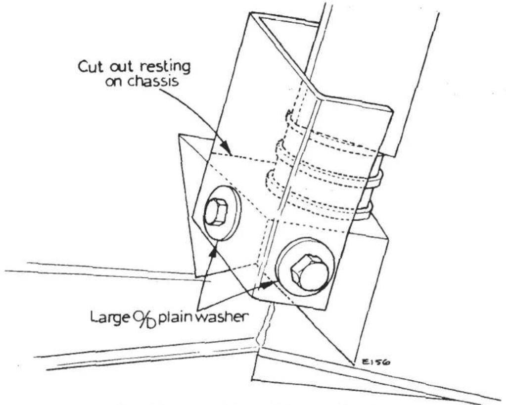
Fig. 25 Heat Shield position on Chassis
ToFit Heatshield
i). Remove the existing heatshield.
ii). Use the illustration as a guide and place the heatshield over the left hand side engine mounting on to the chassis. Once in the correct position use the shield as a template and drill two 8mm clearance holes into the chassis.
iii). Secure the heatshield with two bolts, large plain washers and nyloc nuts in the following order: Bolt head on outside - large o/d plain washer - heatshield - chassis - nyloc nut.
EA.26. - FLYWHEEL & RING GEAR (Manual Transmission)
Since shortly after its introduction, 912 engines have been fitted with a 'flexplate' flywheel' which incorporates a flat steel disc bolted to the crankshaft, the flywheel itself bolting to the outside of the disc. The disc/flywheel assembly is balanced as a unit, and the bolts securing the two parts should never be disturbed.
To Remove
- Remove the clutch assembly from the flywheel (see Section 'Q').
- Release the bolts from the centre of the flywheel and pull flywheel from its locating dowels on the crankshaft.
- Cut between two adjacent teeth on the ring gepr with a hacksaw and split the gear with a chisel.
NOTE: Under NO CIRCUMSTANCES must pressure be applied in attempting to remove the gear for re-positioning the gear on the flywheel.
To Replace
- Check the face of the flywheel for signs of damage from the clutch driven plate. If evident, fit a new flywheel.
- Heat the new ring gear evenly, to a temperature NOT EXCEEDING 315°C. (600°F). Do NOT heat beyond this point, otherwise the wear resistance properties of the gear will be destroyed. Fit the gear to the flywheel with the chamfers on the leading face of the teeth relative to the normal direction of rotation. Allow the ring gear to cool naturally in the air. DO NOT QUENCH.
- Locate the flywheel squarely on the crankshaft flange and upon the locating dowels.
- Apply the Loctite 'AV' to threads in crankshaft, then insert the securing bolts and tighten to the specified torque loading (see TECHNICAL DATA).
- Check the flywheel run-out using a proprietary dial gauge. The total run-out should NOT EXCEED the figure given in TECHNICAL DATA.
- Replace the clutch assembly.
EA.27. - CRANKSHAFT REAR OIL SEAL
To Remove
- One front engined cars, remove the engine/gearbox assembly from the car (Section EA.25.) part gearbox from engine, and mount engine on a suitable stand. On mid engined cars, remove the transmission from the car.
- Remove the flywheel (Section EA.26.)
- Remove the rear oil seal housing by releasing its eight securing setscrews.
- Remove seal from the housing. Discard the gasket.
To Replace
- With the lip of the seal towards the inner machined face of the housing, insert the new seal with the aid of a press, until its inner face is 2.5 mm. (.10 in.) from the machined face, ensuring during this operation that the seal is entered squarely.

Fig. 26
Rear oil seal and housing

Lightly lubricate the lip of the seal, apply "Wellseal" to both sides of a new gasket, and with the aid of Special Tool (84A), fit the oil seal housing over the flywheel flange of the crankshaft, securing with its setscrews. Tighten the setscrews to the torque loading given in TECHNICAL DATA.
NOTE: The lower four screws and washers (into main bearing panel) are special, having a 'thinner' head.
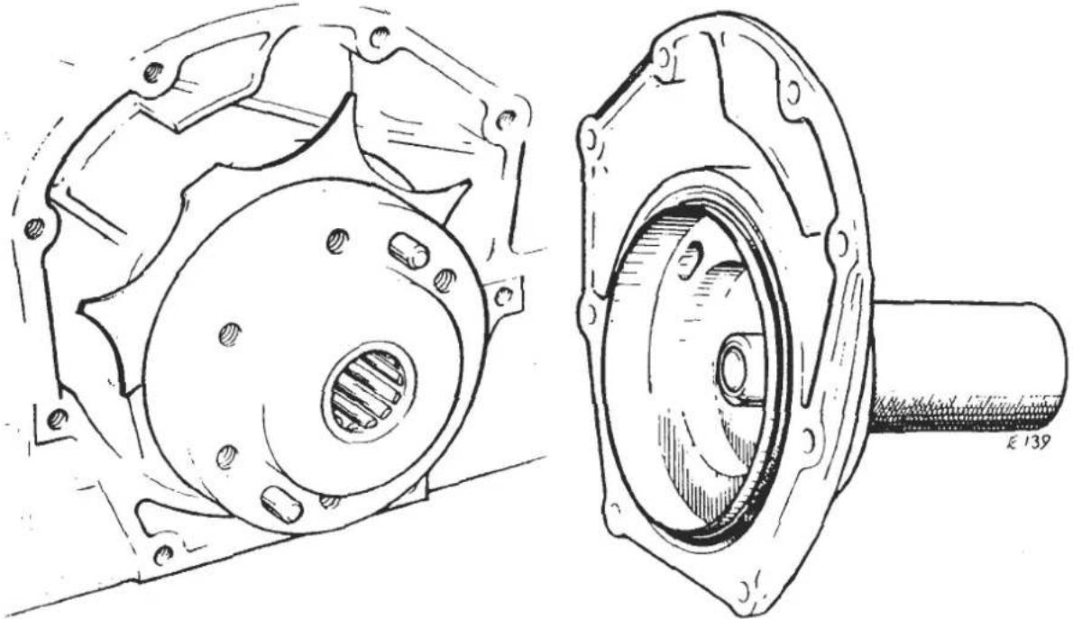
Fig. 28 - Using Tool '84A' to fit rear oil seal housing
- Replace the flywheel.
- Re-assemble the gear box to the engine, and replace engine/gearbox assembly in the car.
EA.28.- CRANKSHAFT
To Remove
- Remove the engine/gearbox assembly from the car(Section EA.25.)part gearbox from engine, and mount engine on a suitable stand.
- Remove the sump (Section EA.23.) (NOT Dry Sump Turbo).
- Remove the front cover (Section EA.17.)
- Remove the rear oil seal housing (Section EA.27.)
- Dry Sump Turbo Only. Remove the 8mm nuts and washers from around the outside of the main bearing panel, followed by the ten large nuts and
washers adjacent to the main journals; all nuts should be released in sequence, working diagonally inwards from the outside. Lift off the main bearing housing. If the housing is tight, it is permissible to tap lightly with a rubber mallet to ease removal. Remove the sprayshield from the rear of the cylinder block.
- Identify each connecting rod bearing cap with its rod, and then unscrew the connecting rod bearing cap bolts by two or three turns, and tap them to release the caps. Push the pistons up into the cylinder liners.
- Remove the auxiliary housing (Section EA.21.) With the aid of Special Tool (83A) remove the union screw securing the oil pick-up pipe in the cylinder block.

Fig. 29 - Oil pick-up pipe and union spanner
- (NOT Dry Sump Turbo)
Remove the ten nuts and washers to the outside of the sump mounting face, followed by the ten large nuts and washers adjacent to the main journals; all nuts should be released in sequence working diagonally inwards from the outside. Remove the oil pick-up pipe and breather pipe from their locations in the main bearing housing and cylinder block. Lift off the main bearing housing. If the housing is tight, it is permissible to tap lightly with a rubber mallet to ease removal. Remove the spray shield from the rear of the cylinder block.
- Lift out the crankshaft. Remove the main shell bearings from both the bearing housing and the cylinder block. Remove the thrust washers from the rear main bearing locations in the cylinder block.
To Replace
-
Fit a new key to the front of the crankshaft to retain the sprocket.
-
Fit a new spigot bearing and new flywheel dowels in the rear (flywheel) end of the crankshaft.
Cross-drilled crankshafts
The 'standard' or non cross drilled crankshaft as fitted to all front engined cars prior to engine no. 23749 (March 1987) has drillings from main bearings 1,2,4 & 5 through to crankpins 1,2,3 & 4 to provide big end lubrication. Both upper and lower shells for these main bearings are provided with a hole to admit oil from a drilling in the block, and a groove to provide an oil channel around which oil may flow to the big end feed drilling in the journal.
The 'cross-drilled' crankshaft is similar in the above respect, but differs as follows: In order to permit the use of plain lower main bearing shells with their increased load bearing area, crank journals 1,2,4 & 5 are also 'cross-drilled' diametrically across from the point where the big end feed drilling emerges. One end of this cross drilling is therefore always in communication with the oil supply channel in the grooved upper main bearing shell, maintaining big end lubrication throughout 360° crankshaft rotation.
This 'cross-drilled' crankshaft is fitted to all Esprit variants from engine no. 13277 (1976), and to Excel models from engine no. 23749 (1987). It is MOST IMPORTANT to refer to the table in section TDA (N/A) or TDB (Turbo) for the correct main bearing shell configuration.
Oversize outside diameter main bearing shells
Whenever main bearing shells are to be replaced on any 907/912/910 engines, it is most important to check whether the block assembly has been bored to accept +0.015 oversize outside diameter mainbearing shells on production.
Remove the main bearing shells, refit the main bearing panel, and measure the main bearing bore diameter.
Standard bore diameter
2.6655 - 2.6660 in.
(67.704 - 67.716mm)
+0.015" O/D bore diameter
2.6805 - 2.6810 in.
(68.085 - 68.097mm)
As a cross check, look for the number stamped on the outside of any main bearing shell with a GROOVE and HOLE
'5690' = Standard Outside Diameter
'5946' = +0.015" Outside Diameter
Block assemblies bored +0.015" oversize on production are normally identified as follows:
907 Engines
'+015' stamped externally on flank at rear of main bearing housing, together with red paint.
912 and 910 Wet Sump Engines
'15' stamped on 4th or 5th main bearing 'cap' (along with another 4 or 5 digit number). Block may also be stamped in the region of engine number (above starter motor).
910 Dry Sump Engine
Stamped externally on side of M.B.P. above rear of scavenge manifold.
Undersize inside diameter shells to suit reground crankshafts are available for both standard and +0.015" overbored blocks. See Parts List.
MODIFICATION OF 910/912 MAIN BEARING PANEL, PRIOR TO ENG. NO 20875
All 912 (naturally aspirated 2.2 litre) and 910 (turbocharged 2.2 litre) engines from engine number 20875, incorporate a revised main bearing panel casting to enable the rear face of No. 5 main bearing to be fully machined in order to reduce oil drain off from the thrust washer face. This panel does not have the chamfer on No.5 main bearing as detailed below.
All engines prior to 20875 should have the following modification carried out ONLY if stripped for any other reason, and show evidence of crankshaft thrust collar wear.
1) Engines with numbers 20793 to 20874 inclusive have been modified in accordance with these instructions at the factory, together with approximately thirty engines prior to 20793. These engines require no further action but care should be taken to order the correct main bearing shells (see paragraph 3).
ii) On all unmodified engines up to No. 20793, remove the main bearing shells from the main bearing panel (M.B.P.) and modify the panel at No.5 (rear) bearing as shown in the diagram.
Using a very fine needle file, carefully form a small chamfer on the right hand corner of the bearing 'cap' from the centre to the rear edge, until the width of the chamfer is 1 - 1.5mm and is approximately 45° to the joint face. take care not to mark any other M.B.P. face with the file.
Thoroughly clean all swarf from the panel.
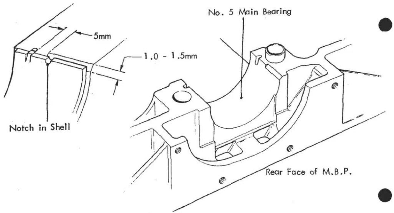
iii) On reassembly, ensure that the correct notched shell is fitted to No.5 (rear) main bearing in the panel.
Part Numbers for the notched bearing shell (ONLY fitted to No.5 bearing LOWER half) are as follows:
Grooved/Hole (912 Elite/Eclat/Excel)
| (Std I/D) | A912E1987S | |
| Std O/D | (-0.010" I/D) | A912E1988S |
| (-0.020" I/D) | A912E1989S | |
| (Std I/D) | A912E1990S | |
| +0.015" O/D | (-0.010" I/D) | A912E1991S |
| (-0.020" I/D) | A912E1992S |
Plain (912 Esprit S3, 910 Esprit Turbo)
| Std O/D | (Std I/D(- 0.010" I/D(- 0.020" I/D | A912E1993SA912E1994SA912E1995S |
| + 0.015" C/D | (Std I/D(- 0.010" I/D(- 0.020" I/D | A912E1996SA912E1997SA912E1998S |
NOTE: Engines from Number 20875, with the revised main bearing panel (without chamfer) do not use the notched bearing shell.
NOTE: 907 (2 litre) engines use a main bearing panel similar to the revised 912 panel and are therefore unaffected by this bulletin.
- Ensure the correct bearing shell configuration is fitted by referring to the table in Technical Data.
Ensure that both the cylinder block and the main bearing housings are clean, then fit new bearing shells. Apply a small amount of graphogen grease to the bearing shells.
- Ensure that the crankshaft main journals are clean, then fit the crankshaft. Spin the crankshaft to ensure even distribution of the graphogen grease. Fit new selective thrustwashers to the rear main bearing so that the oil grooves (the 'copper' side) are towards the crankshaft. Check the end-float between the crankshaft and the thrustwashers (see TECHNICAL DATA). If the end-float is outside this tolerance, replace the selective thrust washers.
- Dry Sump Turbo Only: Ensure the crankshaft connecting rod journals and the connecting rods and caps are clean then fit new bearing shells. Refit the connecting rods and their caps to their respective journals after applying graphogen grease to the bearings. Tighten the bolts to their specified torque loading (see TECHNICAL DATA).
Ensure the scavenge manifold and sump ducts are fitted and the stud locknuts retained with thread locking compound and their locktabs. Insert the oil feed pipe into the block with a 'new 'O' ring fitted on its lower end. Oil the 'O' ring.
- Ensure all the main bearing panel to block locating dowels are in place, and clean the joint face on both parts before applying only 'WELLSEAL' (zero
clearance) compound around the periphery of the joint. Fit the main bearing housing, using a pair of nuts to pull up the joint over the dowels if necessary. Do not tap the housing, as the bearing shells may be disturbed.
-
Fit the nuts and washers tightening the 8mm nuts first, followed by the 12mm nuts in pairs in a sequence outwards from the centre. For torque figures see Technical Data.
-
(Not Dry Sump Turbo)
Ensure that the crankshaft connecting rod journals and the connecting rods and caps are clean, then fit new bearing shells. Refit the connecting rods and their caps to their respective journals, after applying Graphogen grease to the bearings. Tighten the bolts to their specified torque loadings (see TECHNICAL DATA).
- (Not Dry Sump Turbo)
To enable the oil pick up pipe, and the crankcase breather pipe (all 907 and early 912) to be fitted, it is necessary to remove both 12mm nuts from main bearing No. 4. Fit the breather pipe by pushing into its drilling at the rear of the MBH, and refit the 12mm nut end washer to retain. Push the oil pick up pipe into its drilling at the front of the MBH and retain with the main bearing nut and washer. Torque tighten the two main bearing nuts.
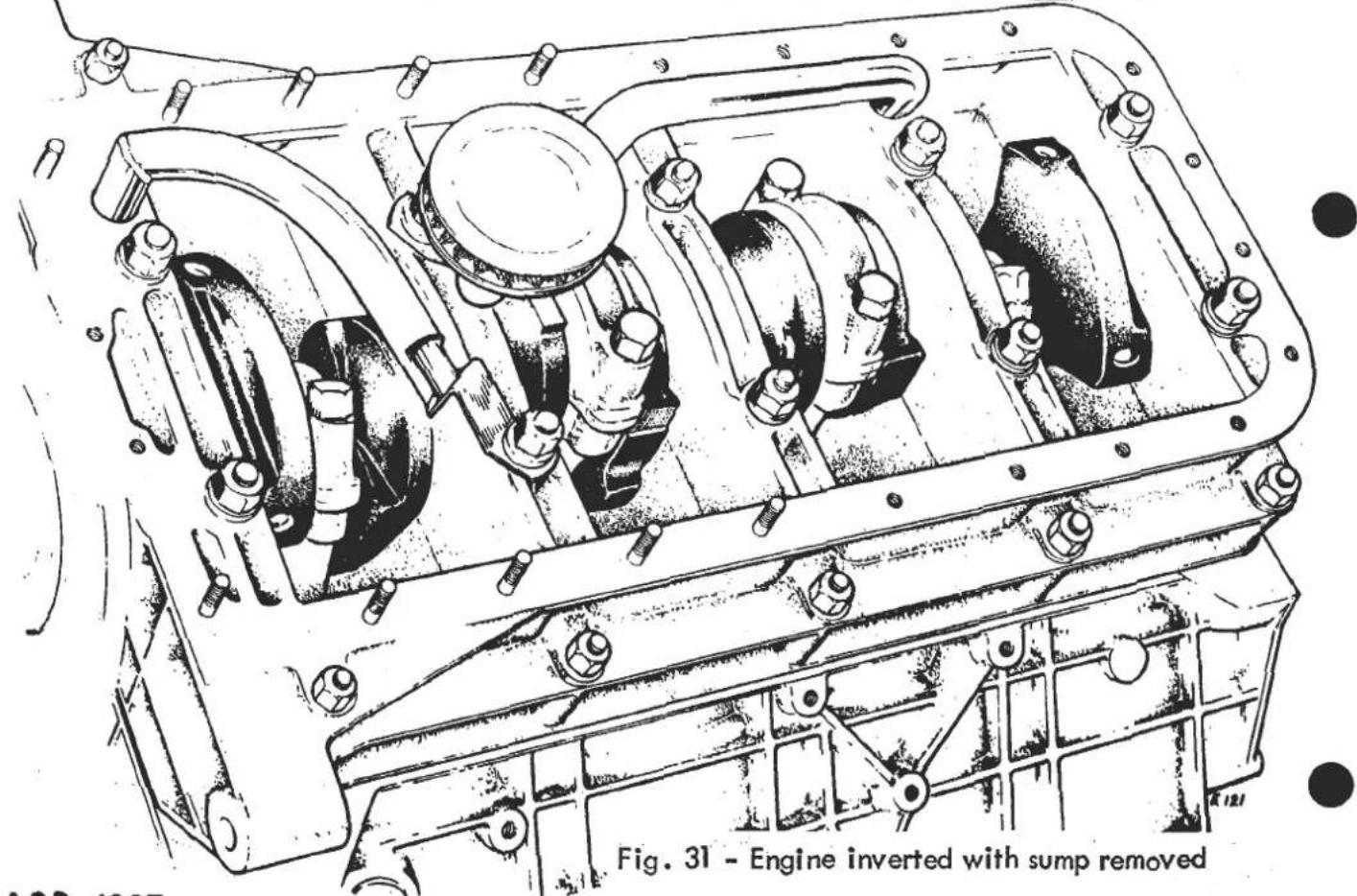
- Coat a new plastic compression olive with engine oil, and from the auxiliary housing chamber, push over the oil pick up pipe/feed pipe and fit the union screw. With the aid of special tool T000T0083A, tighten the union screw to its specified torque loading (see Technical Data).
- Ensure spray shield is in its correct location on cylinder block and main bearing housing, with its flange positioned between the two webs on the main bearing housing. Replace the crankshaft rear oil seal (Section EA.27.)
- Replace the front cover, crankshaft sprocket, sump and flywheel.
- When a new cylinder block is being used, it will be necessary to fit the breather spout at the top of the right hand side below the inlet manifold. Fit the bush, with its flange uppermost, into its location. Tap the breather tube into the bush until approximately 25mm. (1.0 in.) is left protruding. Ensure oil gallery and water jacket plugs are also fitted.
- Re-assemble the gearbox to the engine, and replace engine/gearbox assembly in the car.
EA.29.-PISTONS, PISTON RINGS, CONNECTING RODS & CYLINDER LINERS
To Remove
- Remove engine/gearbox assembly (Section EA.25.)
- Remove cylinder head (Section EA.10.)
- Remove the oil sump (Section EA.23.)
- Remove the connecting rod bearing caps. Remove the ring of carbon from the top of liner wall. Push the piston up and out of the cylinder liner, by its connecting rod. Remove the assembly to a bench.
- Remove the piston rings. Extract the gudgeon pin circlips and push the pin out of the piston, thus releasing the connecting rod. Mark all components in relation to each other, and to the cylinder from which they were removed.
- Using Special Tool T000T0012ZA, withdraw the liners from the cylinder block.

SECTION EA
Fig. 32 - Using Tool T000T0012A
To Replace
- The liners are fitted into the cylinder block with their 'flats' in a front-to-rear line. When replacing liners in the cylinder block, they MUST FIRST be fitted clean and dry, and pushed fully into their locations. At this point, the liner 'nip' should be checked; the
'nip' is the height of the liners ABOVE the cylinder block face and the height of the liners in relation to each other (see TECHNICAL DATA).

Fig. 33 - Using Tool T000T0003A to check cylinder liner height
-
When liner nip is correct, withdraw the liners, apply 'Hylomar' on the liner flange to cylinder block mating face and replace liners.
-
If replacement parts are to be fitted, ensure that the pistons and the connecting rods are both balanced sets.
Note that all 907 and standard 912/910 engines use cast iron cylinder liners with cast aluminium alloy pistons. 912/910 'high compression' engines use forged aluminium alloy cylinder liners with a 'Nikosil' coated bore, together with forged aluminium alloy pistons. The alloy liners have a larger spigot diameter and cannot be fitted to standard engines.
Pistons and liners are only supplied together as matched pairs. Two grade diameters are used, 'A' and 'B' with 'A' piston (marked as crown) fitted into 'A' liners (marked on liner top rim or on side flat) and 'B' into 'B'. Pistons are also weight graded in 3.5 gram (cast pistons) or 3.0 gram (forged pistons) increments, and are marked in the following manner: Cast pistons; coloured paint spot on crown, with corresponding initial letter(s) engraved on gudgeon pin boss underside.
Forged pistons: stamped on crown with 2+, 1+, 0, 1- or 2-. Each engine uses 4 pistons of the same weight grade but may mix 'A' and 'B' piston/liner assemblies. Similarly, connecting rods are weight graded into 2 gram matched sets, and identified by a letter code etched or painted below the forged 'FRONT' mark on the rod.
If ordering an individual connecting rod or piston/liner, the weight grade symbols must be quoted.
Fit each connecting rod to its piston with both 'front' marks facing the same way (forged pistons have arrow stamped on crown pointing forwards) and install the gudgeon pin and circlips.
i) Fit the oil control rings: 907/910/912 Std: The oil control rings consist of an expander ring and two steel rails which are fitted above and below the expander ring. They MUST always be fitted BEFORE the compression rings, working downwards from the piston crown. Fit the expander ring on the piston and ensure that the coloured ends are butting. Fit one end of a steel rail into the groove below the expander ring, holding the rail end with a thumb whilst easing the rail over the piston and into its location, and repeat to fit the other steel rail above the expander. Position the gaps in the two rails, 25mm each side of the expander gap.
912/910 'HC': Fit the expander spring first, followed by the one piece oil control ring, and position the ends of each to be diametrically opposite
ii) Fit the lower compression ring:
907: The step on the outer edge is lowermost
912/910 Std: The chamfer on the inner edge is uppermost.
912/910 'HC': The face is tapered towards the side of the ring marked 'TOP'.
iii) Fit the chrome plated top compression ring
907: May be fitted either way up
912/910 Std: The chamfer on the inner edge is uppermost
912/910 'HC': May be fitted either way up
iv) Position the oil control ring gap to the rear, and the two compression ring gaps 120° to either side.
Running In:
When new rings, or piston/liner sets have been fitted, the running-in period must be 800 kilometres (500 miles), (see Section 'O').
- Using a piston ring compressor, insert the piston into the liner with the 'FRONT' mark towards the front of the cylinder block. Fit cylinder liner clamps after replacing the pistons in the liners.
- Fit new bearing shells to both connecting rod caps securing with their bolts. Tighten all bolts to the specified torque loading (see TECHNICAL DATA).
- Replace the oil sump.
- Replace the cylinder head, after removing the cylinder liner clamps.
- Replace engine/gearbox assembly (Section EA.25.)
EA.30.- CONNECTION OF OIL COOLER THERMOSTAT
Oil cooler thermostats are fitted to late dry sump Turbos and all wet sump Turbos prior to 1986.
Early wet sump cars are fitted with thermostat A910E6550F having 4 5/8" BSP connections, whilst all other cars have thermostat A082E6016F, with 3 x 5/8" BSP connections and 1 x 3/4 " BSP connection.
The large 3/4 " BSP connection is always the inlet connection from the engine, ie from either the scavenge pump (dry sump) or upper connection on oil filter sandwich plate (wet sump)
Thermostats with 4 x 5/8" BSP connections must be viewed down each port and the diagram used below to identify the connections.
Unions clamping the mounting bracket to be coated with 'Omni-Fit' thread lock and torque tightened to 11 kgf.m. (80 lbf.ft) (Dry sump bracket shown)

EA.31.-LUBRICATION SYSTEM PRECAUTIONS
In the event of engine failure involving the possibility of debris entering the lubrication system, it is essential that the following precautions are taken before re-assembly:
i Clean and inspect all engine oilways inblock, crankshaft, cylinder head etc.
ii) Clean and inspect oil pump, pick up pipe and strainer and auxiliary housing.
iii) On 'dry sump' Turbo models, clean and inspect the oil tank and strainer.
iv) Thoroughly flush out oil cooler hoses and clean and inspect oil cooler thermostat.
v) In view of the difficulty of ensuring no debris is retained in the oil cooler, this item must always be replaced in such circumstances.
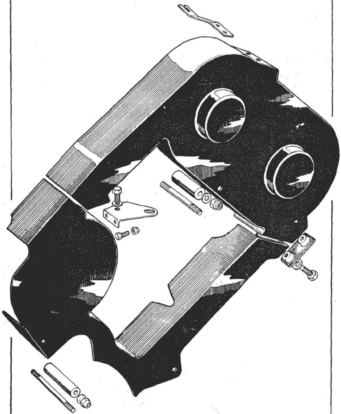
Fig. 10 - Belt guard components (early models)
| T000 T 0002A | Cylinder Liner Clamps to retain cylinder liners | |
| T000 G 0003A | Cylinder Liner Nip GaugeTo check liner height | |
| T000 T 0004A | Valve Guide DriftTo assemble/remove guides | |
| T000 T 0093A | Inlet Valve Seat Drift | |
| T000 T 0094A | Exhaust Valve Seat DriftFor inserting valve seat | |
| T000 T 0009A | Front Cover PilotTo locate front cover | |
| T000 T 0010A | Camshaft Oil Seal InserterFor inserting oil seal | |
| T000 T 0011A | Camshaft Oil Seal ExtractorFor extracting oil seal | |
| T000 T 0012A | Cylinder Liner ExtractorFor extracting liners | |
| T000 T 0072A | Camshaft Oil Seal SleeveFor locating oil seal | |
| T000 T 0083A | Oil Pick-Up Pipe Union SpannerFor tightening union nut | |
| T000 T 0084A | Rear Oil Seal Housing PilotTo locate housing on re-assembly | |
| T000 T 0170A | Crankshaft Sprocket RemoverFor removal of sprocket | |
| T000 T 0242A | Spigot Bearing InserterFor inserting spigot bearing/ aligning clutch assemblyMagnet Assembly(4 off x 2 in long) | To retain cam followers during dismantling |
| T000 T 0290A | Boroughs Gauge | For checking timing belt tension |
| T000 T 0443 | 'Torx' socket | Turbo cam housing bolts |
EA.33.-SEALANTS,ADHESIVES
| Part Number | Product | Application |
| A036E6038VJ | Silastic RTV 732 (315.5 ml) | 907 Cam Covers |
| A907E6257VF | Loctite 504 Gasket Eliminator | Cam Housings |
| A907E6178V | Cylesso | Crank Journals |
| A907E6565V | Molypaul GP2000 | Cam Followers & Shims |
| A907E6119ZA | Wellseal | Crank Rear Seal Housing GasketSump Joint, Cylinder Head GasketMain Bearing Housing |
| A036S6175VH | Hylomar PL32 Medium (100g) | Cylinder Liners to Block |
| A036B6370V | Permabond A115 (50 ml) | Thread locking |
| A074B6009V | Permabond A138 | Push fits |
| A912E6421V | Permabond A136 (200 ml) | 912 Sump Joint |
| A907E6252V | Permabond A121 Pipeseal (50ml) | Dipstick Tube |
Note
Do NOT apply thread locking compound to the following studs:
a. Cylinder Head to Block (12 mm)
b. Main Bearing Housing (12 mm)
c. Main Bearing Housing (8 mm)
d. Cam Housing to Cylinder Head (8 mm)
ENGINE MANAGEMENT
SECTION EMA - U.S.A. ESPRIT TURBO (Prior to '86 M.Y.)
| Operation | Page | |
| Engine Control Components | EMA.1 | 2/3 |
| Engine Management System Check/Set Up Procedure | EMA.2 | 3 to 8 |
| Engine Diagnostic Procedure | EMA.3 | 9 to 23 |
Located beneath front of plenum chamber. Function is to advance ignition on operation of choke. A micro-switch operated by the dashboard end of the choke cable (which also operates the choke tell tale lamp) energises the ignition solenoid. The signal to the distributor vacuum advance capsule (normally connected to No. 1 cylinder throttle edge drilling) is then switched to the vacuum pump, and thus full ignition advance is achieved, together with an increase in engine idle speed.
Fuel Pressure Solenoid
Located beneath rear of plenum chamber. Function is to reduce fuel pressure on 'overun' and idle. A micro-switch, mounted on the front of the front carburettor, and operated by the throttle lever in its fully closed position, energises the fuel pressure solenoid. The signal to the fuel pressure regulator (normally connected to boost pressure in the plenum chamber) is then switched to No. 1 cylinder inlet manifold depression, thus reducing fuel pressure to the carburettors and mixture strength under closed throttle 'overun' conditions.
Throttle Jack Solenoid
Located on the front of the front carburettor. Function is to increase engine idle speed when engine is cold or air conditioning switched on, and also to open throttle on hot start cranking mode. A thermostatic switch fitted into the rear of the inlet manifold water rail, makes contact at water temperature below 70° C, and energises the throttle jack solenoid. To aid cold starting the solenoid is de-energised whilst in the cranking mode. At water temperature above 70° C, the solenoid is energised ONLY whilst cranking to aid hot starting. The solenoid is also energised when the ACU is switched on.
Air Pump & Divertor Valve
The air pump is mounted on the rear of the engine and driven by 'V' belt from the exhaust camshaft. The divertor valve is fitted on the outside of the engine bay left hand wall.
Their function is to provide additional air into either the exhaust ports, or the exhaust catalyst, and reduce engine emissions.
The air pump draws air from a filter located on the right hand rear wheel arch and supplies it to the divertor valve. The divertor valve is spring loaded so as to supply air to the exhaust ports via a non-return valve, and air injection manifold.
When engine coolant temperature reaches 70° C, a solenoid on the divertor valve is energised, and connects a diaphragm chamber on the valve with vacuum supplied by the engine driven pump. This vacuum is used to overcome spring pressure and divert air flow via a non return valve to the exhaust catalyst.
Evaporative Control System
Fuel vapour from the fuel tanks is piped into the catch tank, in which the vapour condenses into liquid fuel and residual vapour. The level of liquid fuel in the catch tank is controlled by the catch tank inlet tube. Any increase in level above this tube and the fuel is induced back into the main tanks. The vapour outlet pipe from the catch tank is routed via a rollover valve to connection 'T' on the vapour (charcoal) canister.
With the ignition switched off, the carburettors are vented via the plenum chamber and carb. vent valve to connection 'C' on the vapour canister. When the ignition is switched on, the carb vent valve solenoid is energised and the pipe is sealed.
The purge connection on the vapour canister (port 'P') is piped to a venturi 'T' piece fitted between the air pump and filter. In this way, when the engine is running air is drawn in through the bottom of the canister, to replace gasoline vapours consumed by the air pump and fed into the exhaust system for oxidation.
EMA. 2. - ENGINE MANAGEMENT SYSTEM CHECK/SET UP PROCEDURE
Special Tools Required
| Lotus Part No: | ||
| 1. | Carburettor Balance Tubes | T000T0496 |
| 2. | Carburettor Idle Mixture Adjuster | T000T0497 |
| 3. | Carburettor Float Setting Bar | T000T0498 |
| 4. | Carburettor Manometer | T000T0499 |
| 5. | Pressure Test Gauge Kit | T000T0500 |
| 6. | Exhaust Sample Probe | T000T0501 |
| 7. | Throttle Damper Setting Bar. | T000T0502 |
| 8. | Special Socket for anti-tamper Distributor Clamp | T000T0503 |
- Remove vacuum tapping screws, fit carburettor balancing tubes and connect to manometer.
Connect pressure test gauge kit as shown in diagram.

Fit exhaust probe to exhaust outlet pipe of turbo charger and connect to CO/HC analyser (e.g. Sun EPA 75 or equivalent). Connect stroboscopic timing lamp to number one spark plug lead.
Exhaust probe connection
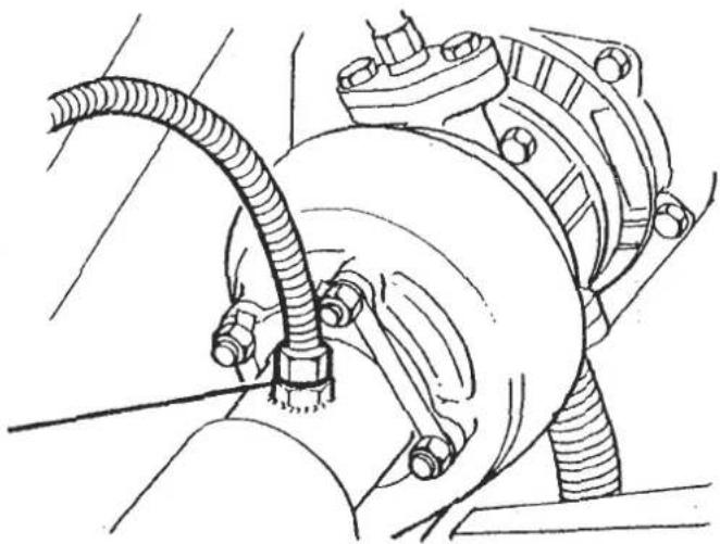
SECTION EMA
COLD Engine
-
Switch on ignition and check that fuel pressure at fuel regulator gauge is to specification 4.0 - 4.5 p.s.i. - if outside specification contact the Service Department of Lotus Performance Cars, L.P.; 530 Walnut Street, Norwood, New Jersey 07648, quoting VIN and engine numbers.
-
Fully operate choke, open throttle fully and release. Start engine and check the following.
i). Vacuum at pump gauge. Minimum = 20" Hg.
ii). Vacuum at ignition solenoid gauge. Minimum 20" Hg.
iii). Position of diffuser flap valve. Should be fully open.
iv). Engine speed rises to approximately 2,500 rpm.
- Return choke fully after 20 - 100 seconds (dependant on temperature) and adjust idle speed at the throttle lever on the front of the carburettors, bearing on the throttle jack solenoid, to 1000 rpm (basic setting).

VIEW FROM FRONT
Disconnect the hose to the air rail pulse valve and check that air is supplied from the hose and reconnect hose.
When a water temperature of 70° C is attained, check that the throttle jack solenoid is deactivated and switches out and check that the air supply to the injection rail hose ceases by temporarily disconnecting hose to the air rail pulse valve. (i.e. air supply is diverted to catalyst).
Allow engine to reach normal running temperature i.e. oil and coolant should be stabilised.
- i). Adjust idle speed to 950 ± 50 rpm.
ii). Adjust ignition timing to 1° BTDC ± 1° .
iii). Check carburettor balance at manometer. Check that all 4 columns are balanced within 3mm, if not re-balance the carburettors. (see Carburettor Balancing Procedure).
iv). Check fuel pressure at the regulator - this should be lower than 3.5 psi at idle. If the pressure is higher the micro switch position on the front carb bracket will require adjustment. Rotate the switch down towards the lever until switch contact is made. Manifold pressure will now be connected to the fuel regulator via the regulator solenoid.
- Mixture setting - with the carbs balanced and rpm and fuel pressure set, the idle mixture can be sampled and adjustment made if required.
i). Switch analyser to sample mode and check readings.
NOTE: Do not touch idle adjustment screws until CO reading has stabilised. The carburettors have been flow tested and only minor adjustment will be required, if any.
ii). CO reading should be within 0.2 to 1.2%. If higher or lower levels are found, remove anti-tamper plugs and move each mixture screw a 1/4 of a turn in or out as the reading dictates, check the CO reading and repeat until the tune specification is reached. A balance between CO and HC is required and the hexane level should be below 550 ppm for a 'new engine' and below 350 ppm for a run-in engine. When adjustment is complete fit anti-tamper plugs.

SECTION EMA
- Fuel regulator micro switch - with the switch set at idle and fuel pressure recorded as in operation 5, open throttle to 2500 rpm and then return throttle to idle position. Check that when the engine speed is above 1800 rpm, the micro switch is deactivated allowing fuel pressure to increase to 4.0 - 5.0 psi. Repeat this test and check that pressure differences are maintained.
NOTE (1). Failure to change pressure is a serious malfunction. Check pipework and electrical circuit for defects. Rework the defective items before further testing.
(2). The throttle will be delayed in returning to the idle position due to the action of the damper valve (see number 8).
- Damper valve - with adjustments 1-7 carried out the throttle damper can now be adjusted. With the engine at idle rpm rotate the damper until a distance between damper body and lever is 0.55 ± .05 in. Lock up the retaining nut, open throttle to 2500 rpm and release. Idle rpm should be attained within 0.8 to 2.0 seconds.

VIEW FROM REAR
- ACU throttle jack solenoid - with adjustments 1 - 8 carried out, switch on air conditioning and then disconnect red wire from compressor where it joins the pink/blue at the right hand front of the engine bay. Note engine rpm.
Initial adjustment was completed in paragraph 4. The engine speed should rise to 1100 rpm ( ± 25 rpm). If further adjustment is required, adjust on the front carburettor lever. After completion, reconnect compressor lead.
-
Flap valve actuator - with all adjustments completed switch off engine and check that the diffuser flap valve closes fully within 15 secs.
-
Hot restart - crank over engine and check that the throttle jack solenoid is operating in the cranking mode.
-
To check maximum vacuum from vacuum pump, clamp off the vacuum hose at air box to 'T'-connection and note increase in pump vacuum. This should rise by approximately 3" Hg.
-
On completion disconnect pressure test gauge kit from components and re-connect fuel and vacuum pipes securely. When connecting vacuum pipes spray connections with a "silicone" aerosol and push on connections firmly. Disconnect manometer, remove balancing tubes and replace vacuum tapping screws securely. Fit new anti-tamper plugs to both throttle coupling screws, 4 balancing screws and 4 mixture screws.
EMA.3.- ENGINE DIAGNOSTIC PROCEDURE
Before carrying out detailed diagnostic check, ensure engine management system is within specification.
| COLD START PROBLEMSPossible causes: | Sub-Group |
| Weak battery (recharge or replace) | J |
| Fuel pump electrical circuit | I |
| Leak in intake manifold | A |
| Distributor capHigh tension leadsRotorSpark plugs | B |
| Cold start maladjustment | C |
| Cam timing incorrect | D |
| Control pressure, too lowFuel pump capacity unsatisfactoryFuel lines (filter) clogged | E |
| CO misadjustment | G |
| Thermal switch incorrect | H |
| HOT START PROBLEMSPossible causes: | Sub-Group |
| Fuel pump electrical circuit | I |
| Leak in intake manifold | A |
| Spark plugs | B |
| Cold start maladjustment | C |
| Cam timing incorrect | D |
| Control pressure incorrectFuel system, external leakageFuel system internal leakage | E |
| CO maladjustment | G |
| Thermal switch incorrect | H |
Before carrying out detailed diagnostic check, ensure engine management system is within specification.
| UNEVEN RUNNINGPossible causes: | Sub-Group |
| Leak in intake system | A |
| Distributor capHigh tension leadsCylinder compressionSpark plugs | B |
| Cold start maladjustment | C |
| Cam timing incorrect | D |
| Incorrect control pressureFuel lines (filters) cloggedFuel pump capacityunsatisfatory | E |
| Throttle or throttlelinkage misadjustmentIncorrect balance | F |
| CO maladjustment | G |
| ENGINE STALLSPossible causes: | Sub-Group |
| Fuel pump electrical circuit | I |
| Leak in intake system | A |
| Distributor capHigh tension leads | B |
| Fuel lines (filters) cloggedFuel pump capacity unsatisfactory | E |
| CO maladjustment | G |
| POOR PERFORMANCE, LOW TOP SPEEDPossible causes: | Sub-Group |
| Leak in intake systemAir filter clogged | A |
| Distributor capHigh tension leadsCylinder compressionSpark plugsIgnition timing incorrect | B |
| Cold start maladjustment | C |
| Cam timing incorrect | D |
| Control pressure maladjustmentFuel lines (filters) cloggedFuel pump capacity unsatisfactoryIncorrect vacuum control of the control pressure | E |
| Throttle or linkage maladjustment | F |
| CO maladjustment | G |
| EXCESSIVE FUEL CONSUMPTIONPossible causes: | Sub-Group |
| Cylinder compression | B |
| Cold start maladjustment | C |
| Control pressure incorrect | E |
| Ignition timing incorrect | B |
| CO maladjustment | G |
SUB GROUP 'A' - Intake Manifold Leaks & Air Filter Inspection
- Check for air leaks at the carburettor to manifold joint.
The spacer plates and 'O' rings used at this joint act as insulators to absorb vibration and prevent frothing of fuel in the float chambers. It is essential that the carburettor mountings are not overtightened, as the 'O' rings may be displaced with a resultant air leak.
A uniform gap between spacer plate and carburettor, and between spacer plate and inlet manifold must be maintained as shown below.
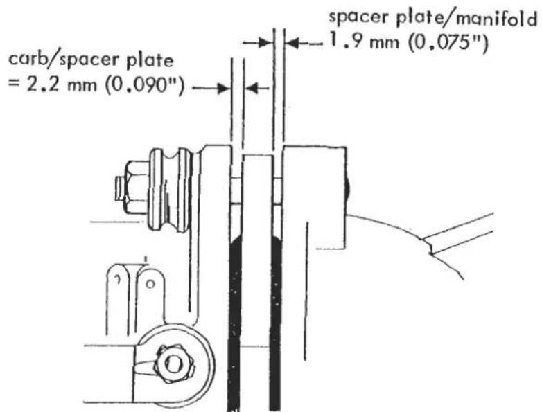
- Check for air leaks at carburettor balance pipe connections, and at cold start air intake pipe connections to carbs and diffuser.
Check torque of banjo bolts : 2.2 kgf.m (16 lbf.ft)

- Check for air leaks at the inlet manifold to cylinder head joint.
- Check for air leak from inlet manifold pressure take off adaptor (no. 1 cylinder) and for leak or disconnection of pipe from adaptor to fuel pressure regulator solenoid.
- Inspect the air filter element.
Release the filter cover from the engine bay wall, leave the hoses attached and pull open. Remove the cleaner element and inspect condition.
If necessary, remove the rubber seal, and discard the element. Ensure the seal is in good condition (replace if necessary) and fit in position on the new element.
Note: The seal joint must be at the centre top. Clean the inside of the air cleaner body and cover, keeping dust out of the intake trunking. Fit new element with its metal face towards the carburettors and replace cover.

A). Check for a spark at each plug lead. If all are sparking, remove plugs and check condition. If serviceable, clean and gap to 0.9 mm (0.035"). Before replacing plugs, check cylinder compressions as (B). If no spark at leads, proceed as TEST 1.
| TEST | RESULT | |||
1 CHECK HT SPARKING | Should be:Regular sparking TEST6No sparking TEST 2 | |||
 | Measure voltages at 1-4 incl. should be:1-More than 11.5V2-1V max. below V at 13-1V max. below V at 14-0V-0.1VAll correct TEST 3Incorrect reading(s) SEE CHART | |||
| 1 | 2 | 3 | 4 | SUSPECT |
| LOW | √ | √ | √ | Battery discharged |
| √ | LOW | LOW | √ | Ignition switch and/or wiring |
| √ | √ | LOW | √ | Coil or amplifier |
| √ | √ | √ | HIGH | Amplifier earth (ground) |
3 CHECK AMPLIFIER SWITCHING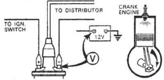 | Voltage increases while cranking TEST 5Voltage does not increase while cranking TEST 4 | |||
| 4 PICK-UP COIL RESISTANCE45DMΩ | Ohmmeter should show 2-5 kΩCorrectChange amplifierIf engine will not start TEST 5IncorrectChange pick-upIf engine will not start TEST 5 | |||
| 1 | 2 | 3 | 4 | SUSPECT |
| LOW | √ | √ | √ | Battery discharged |
| √ | LOW | LOW | √ | Ignition switch and/or wiring |
| √ | √ | LOW | √ | Coil or amplifier |
| √ | √ | √ | HIGH | Amplifier earth (ground) |
| 4 PICK-UP COIL RESISTANCE | Ohmmeter should show 2-5 kΩ |
 | CorrectChange amplifierIf engine will not startTEST 5IncorrectChange pick-upIf engine will not startTEST 5 |
5 CHECK HT SPARKING | Should be good HT sparking TEST 6 TEST 6 |
6 CHECK ROTOR ARM | Should be: |
| 7 VISUAL AND HT CABLE CHECKSEXAMINE1 Distributor Cover2 Coil Top3 H.T. Cable Insulation4 H.T. Cable Continuity5 Spark Plugs | Should be:1 Clean, dry, no tracking marks2 Clean, dry, no tracking marks3 Must not be cracked, chafed or perished4 Must not be open circuit5 Clean, dry, and set to correct gap |
B). Check cylinder compressions: Remove spark plugs. Connect a remote control switch to battery and starter motor solenoid.
Use a compression tester to measure cylinder compressions with throttle fully open.
Check that cylinder compressions are fairly even.
| Cold engine (dry bores) | - | 120 p.s.i. minimum | (at sea level) |
| Hot engine | - | 130 p.s.i. minimum | (at sea level) |
C). Check ignition timing:
Nominal static and idle: 1° BTDC ( + 1° ) @ 4,000 rpm with vacuum pipes disconnected from capsule: 17° BTDC ( + 2° )
SUB GROUP C - Cold Start System Maladjustment
- Check that operation of the choke control results in full travel of the carburettor cold start levers.
With the choke control in the 'off' position both carb levers should contact their closed 'stops' on the carburettor tops. With the choke control operated fully, check that both levers are against their fully open stops. Adjust the choke cable at the carburettor, and linkage if necessary.

SUB GROUP D - Check Cam Timing
- Turn the engine to No. 1 cylinder TDC with the camshaft toothed pulley timing marks facing EACH OTHER innermost.
Note: The engine may beset at TDC by reference to the timing marks on the flywheel, and pointer located at the top of the clutch housing, as shown.
- Check that the pulley dots (red on inlet, green on exhaust) are aligned with a line through the camshaft pulley centres. These dots may be viewed from either the front side (using a mirror) or the rear side.
If the engine is running, the rear side of the pulleys may be viewed with a stroboscope set at TDC or No. 1 cylinder.
Note: It is most important that each camshaft toothed pulley is fitted the correct way round, i.e. 'IN' facing forward on inlet camshaft and 'EX' facing forward on exhaust camshaft. Marks on the reverse side of the pulley will be reversed.

SUB GROUP E - Fuel Control Pressure
- Connect fuel pressure test gauge as shown below.

Switch on ignition and check fuel pressure = 4.0 - 4.5 p.s.i. If outside specification, remove anti-tamper plug from fuel pressure regulator adjustment screw, and adjust as necessary.
If the pressure reading is too high, and cannot readily be adjusted to specification, a restriction in the return line is indicated. Rectify as necessary.
If the pressure reading is too low, and cannot readily be adjusted to specification, a restriction in the supply line, or faulty fuel pump is indicated.
Check for an unrestricted supply to the fuel pump, and for fuel filter restriction. Test fuel pump
- Start engine and allow to reach normal running temperature.
Check fuel pressure at the regulator. This should be lower than 3.5 p.si. at idle (950 ± 50 rpm). If above specification, check that the micro-switch on the front of the front carburettor is activated. If not, rotate the switch down towards the lever until switch contact is made.
View from front

If switch adjustment is carried out, open throttle to 2500 rpm and then return throttle to idle position. Check that when engine speed is above 1800 rpm, the micro-switch is deactivated allowing fuel pressure to increase to 4.0 - 5.0 p.s.i. Repeat this test and check that pressure differences are maintained. Adjust switch position if necessary but always ensure that idle pressure requirements are met.
If switch contact is made at idle, but fuel pressure remains above 3.5 p.s.i, check fuel pressure regulator solenoid pipework and wiring for leakage or disconnection. If no fault is found, replace fuel pressure regulator solenoid valve.
- If pressures are found to be correct, remove carburettor tops and check fuel inlet filters, cleaning if necessary. Remove float needle valves and inspect seating. Replace if necessary. Check float height setting = 14.5 - 15.0 mm.
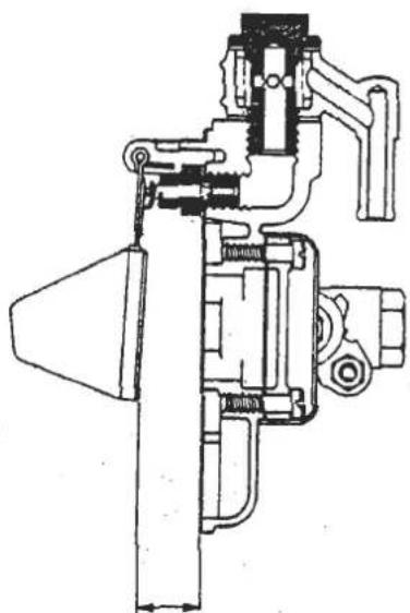
APR 1987
Float height with gasket in position
SUB GROUP F - Carburettor Balance
- Remove vacuum tapping screws, fit carburettor balancing tubes and connect to manometer.
- Adjust throttle stop screw to give specified idle speed of 950 ± 50 r.p.m. with engine at normal operating temperature. Check that all 4 columns are balanced within 3mm. If not continue balancing procedure.

- Remove anti-tamper plugs to gain access to the throttle coupling and balancing screws.
Ensure that all balancing screws are closed. (do not graunch). - Whilst maintaining idle speed, adjust throttle coupling screws to balance lower of columns 1, 2 with lower of column 3, 4.
NOTE: Ensure that both clamping screws on the balance lever are in secure contact with the balance arm. - Considering the carburettor barrels in pairs (1, 2 and 3,4) note which of the two mercury columns for each pair is higher and gradually move only the corresponding balancing screw until the two mercury columns of each pair are balanced within 3mm. Maintain correct idle speed and ensure that all 4 mercury columns are within 3mm.
- On completion disconnect manometer and remove balancing tubes and replace vacuum tapping screws securely. Fit new anti-tamper plugs to both throttle coupling screws, 4 balancing screws and 4 mixture screws.
Ensure that fuel pipe connections are secure.
- Fit exhaust probe to exhaust outlet pipe of turbocharger and connect to CO/HC analyser (e.g. Sun EPA 75 or equivalent).

Start engine and allow to reach normal running temperature i.e. oil and coolant temperatures stabilised.
- Switch analyser to sample mode and check readings.
Note: Do not touch idle adjustment screws until CO reading has stabilised.
CO reading should be between 0.2 - 1.2%. If higher or lower levels are found ensure carburettors are balanced (see Sub Group F) before continuing.
Remove anti-tamper plugs and move each mixture screw 1/4 of a turn in or out as the reading dictates. Check the CO reading and repeat procedure until correct specification is achieved. A balance between CO and HC is required, and the Hexane level should be below 550 ppm for a 'new' engine and below 350 ppm for a 'run-in' engine.
- When adjustment is complete, fit anti-tamper plugs.
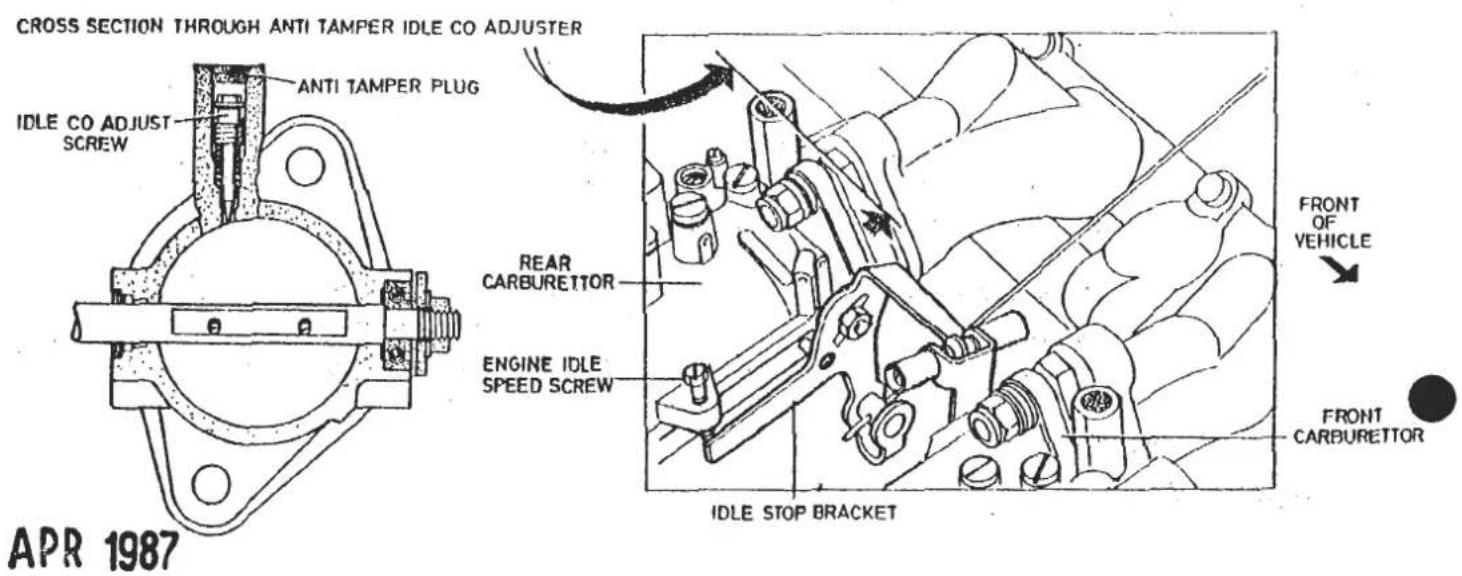
SUB GROUP H - Thermal Switch
- In order to test correct operation of the thermal switch, sufficient coolant must first be drained from the cooling system to permit the removal of the switch from the rear of the inlet manifold.
- Place the switch bulb in a pan of water, with a battery and bulb connected across the switch terminals and a thermometer measuring water temperature. Heat the water and check make and break temperatures meet specification.
Maximum break on rise = 70° C
Minimum make on fall = 60° C
SUB GROUP J - Battery Re-charging Procedure
Instructions for Tungstone Powermaster Maintenance Free Batteries.
To determine the state of charge of the battery, apply a brief discharge of no more than ten seconds duration (e.g. turn on headlights) with the engine off, and then allow to stand on open circuit for two to three minutes.
Measure the terminal voltage of the battery.
If steady voltage is below 12.4 Volts, recharge battery as follows.
Note: The battery must not be boost charged.
If necessary, fit a replacement battery to the vehicle, whilst original battery is charged as follows.
Remove battery from vehicle.
a). Constant Current: The battery must be charged at a maximum of 5 amps until the battery terminal voltage (on charge) has stabilised over a one hour period, at which time the voltage will be in the range 16.0 - 16.5 V. At this stage the battery must be taken off charge IMMEDIATELY, to prevent excess gassing with resulting water loss which will ultimately reduce the guaranteed service life.
b). Constant Voltage: The battery may be charged at a voltage up to a maximum of 15.8V providing the current is carefully monitored and the charge terminated when the current has tapered off and changes by less than 0.1 amp over a period of one hour. If it is not possible to monitor the current during charging, then the voltage must be restricted to 14.4 V maximum.

Battery access
SUB SECTION I - Fuel Pump Electrical Circuit
1. Check safety inertia switch has not been activated.
The switch is located in the ignition box at the rear of the engine bay. To re-set the switch, press down the plunger appearing through the hole in the top of the ignition box.

Inertia switch
Check for electrical feed at fuel pump terminals with ignition switched on.

ENGINE MANAGEMENT
SECTION EMC - ESPRIT TURBO 1987 MODEL YEAR (Domestic & Export)
| Operation | Page | |
| Vacuum Connection Diagram | EMC.1 | 2/3 |
| Thermal Ignition Advance | EMC.2 | 4 to 6 |
| Crankcase Breather Valve | EMC.3 | 6 |
| Cold Enrichment Thermal Valve | EMC.4 | 7 |
| Plenum Purge | EMC.5 | 7 |
| Throttle Jack Solenoid | EMC.6 | 7/8 |
| Overboost Switch | EMC.7 | 8 |
| Idle Speed & Ignition Timing Setting Procedure | EMC.8 | 8 to 10 |
EMC.1.- ENGINE MANAGEMENT VACUUM CONNECTION DIAGRAM
![graph TD A["CRANKCASE BREATHER VALVE ⑩"] -->|TO AIRBOX| B["BLACK"] B --> C["1 D 2"] C --> D["TO CRANKCASE"] D --> E["BLACK/WHITE"] E --> F["COLD ENRICHMENT THERMAL VALVE ⑨"] F --> G["NON RETURN VALVE ⑧"] G --> H["BLACK/RED"] H --> I["BLACK/BLUE"] I --> J["DISTRIBUTOR"] J --> K["BLACK"] K --> L["THER…](/content/2026/05/1021120/images/33c222d7667fa2bc6613ce95775340fa6533148c94005a8bc5d6cd67586b6ec8.jpg)
Page 2

SECTION EMC
- Vacuum Pump: Mounted L.H. side of crankcase. Driven by 'V' belt from crankshaft. Supplies vacuum for engine management, brake servo and heater/a.c.
- Thermal Switch: Fitted in thermostat outlet water pipe. M.O.R. 70°C. B.O.F. 60°C. Switches I.S.V. and purge pump. See EMC.2.
- Ignition Solenoid Valve I.S.V.: Fitted on top of R.H. fuel tank board. Controlled by thermal switch (item 2). Removes vacuum signal to distributor during cold cranking, (aids start up) and at water temps. above 70°C, (safeguard in case of T.I.V. failure) See EMC.2.
- Overboost Switch: Fitted on top of R.H. fuel tank board. Cuts out ignition if overboost is detected (wastegate failure). See EMC.7.
- Purge Pump: Fitted to tailgate aperture R.H. stiffener bracket. Controlled by thermal switch (item 2) Operates at water temps. above 70°C. with ignition off, to aid hot re-start. See EMC.5.
- Shut Off Solenoid Valve: Fitted adjacent to purge pump. Shuts off purge pump line with ignition on to prevent loss of boost pressure through purge pump. See EMC.5.
-
Engine Speed Sensing Relay: Fitted inside R.H. wheelarch in rear luggage compartment Energises throttle jack above 1400 rpm on fall (1600 rpm on rise) to reduce emissions on overrun. See EMC.6.
-
Non Return Valve: Fitted in line, between thermal valve and carbs. Prevents boost pressure blowing off through thermal valve. See EMC.3.
- Cold Enrichment Thermal Valve: Fitted into rear of inlet manifold water rail. At water temps below 53°C, valve shuts off crankcase breather bleed, to enrich fuelling. See EMC.4.
- Crankcase Breather Valve: Fitted at top rear of crankcase. Vents crankcase emissions to airbox with bleed to carbs. See EMC.3.
- Thermal Ignition Valve: Fitted to centre of inlet manifold water rail. Below 60°C directs vacuum pump signal to distributor for full advance to aid cold idle and driveability. See EMC.2.
- Throttle Jack Solenoid: Fitted to front of front carburettor. Controlled by speed sensing relay (item 7), choke switch and a.c. switch. Energised above 1400 rpm to reduce emissions on overrun and when choke/a.c. operated to raise/maintain idle speed. See EMC.6.
- Fuel Pressure Regulation Valve: Mounted to rear of carb. plenum. Adds boost pressure to fuel delivery pressure from pump to maintain fuel delivery to carbs. at 0.27 ± 0.02 bar (4.0 ± 0.25 lb/in²) above boost pressure. See LB.1.
EMC.2. - THERMAL IGNITION ADVANCE
The thermal ignition advance system is designed to provide maximum ignition advance at low engine temperature to aid cold driveability and increase idle speed.
The distributor is fitted with a double sided vacuum advance capsule, one side of which is permanently connected to the plenum chamber (boost pressure). The opposite side of the capsule is connected, via the Thermal Ignition Valve (T.I.V.) and Ignition Solenoid Valve (I.S.V.) to either the vacuum pump or throttle edge drilling.
The T.I.V. is fitted into the centre of the inlet manifold water rail, and at coolant temperatures below 60°C, connects ports 'D' and '1'. Above 60°C, ports 'D' and '2' are connected.
The I.S.V. is mounted on top of the right hand fuel tank board and is controlled by a thermal switch fitted into the thermostat housing outlet pipe at the front of the engine bay. At coolant temperatures below 70°C (on rise) the I.S.V. is energised and connects ports '2' and '3'. Above 70°C the solenoid is de-energised and connects ports '1' and '3'.
The I.S.V. is de-energised during engine cranking regardless of coolant temperature.
Vacuum Circuits
Water Temp: inlet manifold below 60°C
At coolant temperatures (inlet manifold) below 60°C, the T.I.V. and (energised) I.S.V. direct a vacuum pump signal to the distributor advance capsule to provide over 30°C ignition advance to aid cold driveability and increase idle speed.
![graph TD A["IGNITION SOLENOID VALVE"] --> B["2 3 1"] B --> C["PILENUM"] C --> D["DISTRIBUTOR"] D --> E["FRONT CARB."] E --> F["THROTTLE EDGE PORT"] F --> G["VACUUM PUMP"] G --> H["THERMAL SWITCH"] I["THERMAL IGNITION VALVE"] --> J["2 D 1"] K["below 60°C"] --> L["res low 60°C, raised) to m distributo…](/content/2026/05/1021120/images/adeefac74b1545b962f5d814d40459b29f7f38a5561e5483fca386626258da82.jpg)
SECTION EMC
Water Temp: inlet manifold below 60°C Engine Cranking
To aid starting a cold engine, the I.S.V. is de-energised during cranking in order to provide a plenum chamber pressure signal to the distributor for no vacuum advance.
![graph TD A["IGNITION SOLENOID VALVE"] --> B["2 3 1"] B --> C["IGNITION IGNITION VALVE"] C --> D["DISTRIBUTOR"] D --> E["RETAIN CARB."] D --> F["FRONT CARB."] D --> G["THROTTLE EDGE PORT"] G --> H["THERMAL SWITCH"] I["ELow 60°C"] --> J["Ground"] K["VACUUM PUMP"] --> L["Main Component"] M["Distributor…](/content/2026/05/1021120/images/1302be079fce7bf5e5a1968bff7010b293a89f0c5b3b6f291bb2834d210af51e.jpg)
Water Temp: inlet manifold above 60° C thermostat pipe below 70° C
When the coolant temperature (inlet manifold) reaches 60°C, the T.I.V. changes over and directs a throttle edge drilling vacuum signal to the distributor for normal running ignition advance.
![graph TD A["THERMAL IGNITION VALVE"] --> B["2 D 1"] B --> C["DISTRIBUTOR"] C --> D["REAR CARB."] C --> E["FRONT CARB."] C --> F["PLENUM"] F --> G["THROTTLE EDGE PORT"] G --> H["THERMAL SWITCH"] I["VACUUM PUMP"] --> J["End"]](/content/2026/05/1021120/images/6620f7446d88c3685fe5cd61b63608cd45391a7d41fbe3445262053d5d685567.jpg)
Water Temp: thermostat pipe above 70°C
In order to safeguard the engine from potentially damaging excessive ignition advance at normal running temperature, should a malfunction of the T.I.V. occur: When coolant temperature (thermostat pipe) reaches 70°C (on rise) the I.S.V. is de-energised, and directs a plenum chamber pressure (instead of vacuum pump) signal to the T.I.V.
![graph TD A["IGNITION SOLENOID VALVE"] --> B["2 3 1"] B --> C["PILENUM"] C --> D["DISTRIBUTOR"] D --> E["VACUUM PUMP"] E --> F["THROTTLE EDGE PORT"] F --> G["THERMAL SWITCH"] H["the lly nition ning I.V. at n rise) gised, chamber vacuum .I.V."] --> A style A fill:#f9f,stroke:#333 style B fill:#ccf,str…](/content/2026/05/1021120/images/c8a072de00f437e4f483b8ec9a5ad49332920960e32307bdbe3eab6d451a3b4e.jpg)
EMC.3. - CRANKCASE BREATHER VALVE
A one way breather valve is connected between the crankcase breather spigot at the rear of the block, and the airbox. Crankcase emissions developed during normal running are able to vent through the one way valve into the airbox.
In order to prevent these fumes, under low airflow engine idle conditions, escaping through the inlet trunking to atmosphere the valve is also connected via a small bore hose to the carburettors. This enables the small quantity of crankcase fumes at idle to pass directly into the carburettors and intake tract and suppresses opening of the breather valve.
The carburation is calibrated to compensate for this degree of airflow by-passing the venturis.
A one way (non-return) valve is fitted between the breather valve and carbs. to prevent reverse flow when boost pressure exceeds crankcase pressure. The black side of the valve must be fitted towards the carburettors.
EMC.4. - COLD ENRICHMENT THERMAL VALVE
The cold enrichment thermal valve is designed to enrich fuelling at low engine temperatures to improve driveability.
The valve is fitted into the rear of the inlet manifold water rail. Port 'D' is connected with port '1' at coolant temperatures below 53°C and with port '2' above 53°.
The small bore crankcase breather pipe between breather valve and carburettors is connected to the thermal valve via ports 'D' and '2', with port '1' being blanked off. Thus at low engine temperature, the breather circuit to the carbs is shut off, and enriched fuelling results from the decrease in calibrated airflow past the throttle plates. At higher temperatures the breather line is restored and fuelling returns to normal.
EMC.5. - PLENUM PURGE
The purge pump is designed to induce ambient air into the carburettor plenum chamber of a hot engine when switched off. This improves hot starting of the engine.
The pump is fitted on the tailgate aperture R.H. support bracket, behind the quarter window trim panel in the rear luggage compartment, and is operative only when the ignition is switched off. A thermal switch in the thermostat outlet pipe (also used for the ignition solenoid valve) energises the purge pump at water temperatures above 70°C (on rise) until coolant temperature falls to 60°C.
A solenoid valve mounted just below the purge pump, is energised with the ignition on, to shut off the purge line, and prevent boost pressure blowing off through the pump.
EMC.6. - THROTTLE JACK SOLENOID
The throttle jack solenoid is designed to
i) prevent complete throttle closure on overrun to reduce emissions and inhibit stalling.
ii) increase idle speed when the choke control is operated
iii) maintain idle speed when the air conditioning (if fitted)
is operating
The solenoid is fitted to the front of the front carburettor and operates a lever attached to the front end of the throttle spindle.
The solenoid is energised under any of the following conditions:
a) Above engine speed of 1400 rpm on fall (1600 rpm on rise) as sensed by the engine speed sensing relay, to prevent complete throttle closure on overrun to reduce hydrocarbon emissions and inhibit stalling. The relay is mounted on the wheelarch alongside the R.H. rear of the engine bay.
b) When the choke control is operated, to increase idle speed. The choke micro-switch is integral with the choke cable assembly at the fascia end, and is also used to operate the choke tell tale. This switch operates a throttle jack relay located adjacent to the engine speed sensing relay.
c) When the air ocditioning (if fitted) compressor is operating, in order to maintain idle speed.
To set up: With the engine at normal running temperature, without the air conditioning switched on, check/adjust idle speed at the normal stop screw on the front of the rear carburettor. Correct setting 850-950 rpm.
Energise the solenoid with 12 volts and adjust the lever screw (against which the solenoid button operates) to obtain an engine speed of 1200 rpm and then de-energise.
Test each of the three activating systems and observe the action of the solenoid.
EMC.7. - OVERBOOST SWITCH
The overboost switch is fitted to safeguard the engine against excessive boost pressure in the event of wastegate failure by cutting out the ignition.
The switch is mounted on the right hand fuel tank board and is connected to the crankcase breather bleed/cold enrichment system in order to monitor the boost pressure signal downstream of the throttle butterflies. If a pressure greater then 0.71 bar (10.5 lb/in²) is sensed, the switch cuts out the feed to the ignition coil.
EMC.8. IDLE SPEED & IGNITION TIMING SETTING PROCEDURE
i) Ignition Timing Initial Setting:
If the engine has been rebuilt, or the distributor replaced, an initial setting of the ignition timing must be made to enable the engine to run. Set the crankshaft to 10° BTDC using the timing marks on the flywheel and clutch housing with the rotor arm pointing towards no.1 terminal on the distributor cap. Pull off the rotor arm and plastic shield and turn the distributor body to align the pick up sensor with the adjacent projection on the reluctor (equivalent to the cam on a contact breaker system). The engine may now be started and run up to normal operating temperature.
Initial Ignition Timing Setting
Connected to port 'D' of T.I.V.
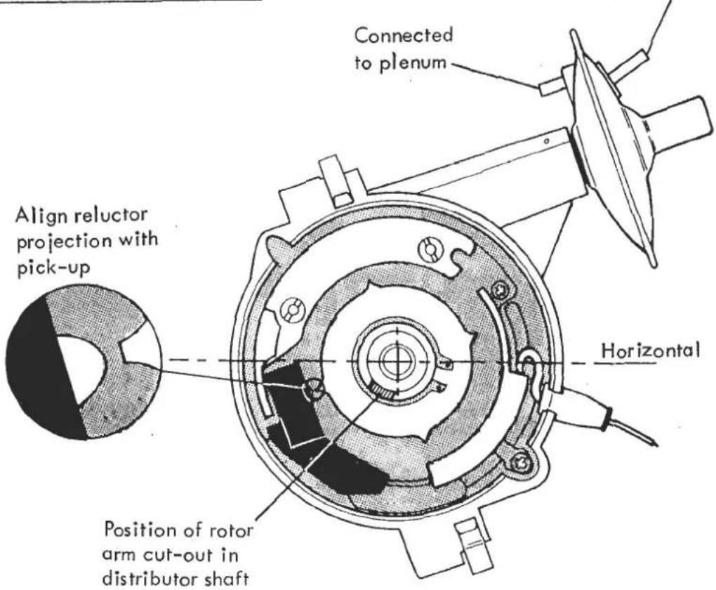
ii) Check/Adjust Ignition Timing:
Start the engine and run up to normal operating temperature to ensure the T.I.V. switches the distributor capsule to the throttle edge port.
Using a stroboscope, check/adjust the ignition timing to 10° BTDC at hot idle. Timing marks are provided on the flywheel rim, with an aperture and pointer in the top of the clutch housing, adjacent to the starter motor. Pull out the protective grommet, and refit after adjustment.

To check the centrifugal advance operation, first disconnect and plug, or clamp off the vacuum hose from the distributor capsule.
Check centrifugal advance characteristics are as follows:
| crank rpm |
| Below 1,000 |
| 2,000 |
| 5,000 |
iii) Check/Adjust Idle Speed:
Start engine and run up to normal operating temperature.
Check that the air conditioning (if fitted) is switched off.
Adjust idle speed, at the stop screw, on the front of the rear carburettor, to 900 ± 50 rpm.
Use the cable adjuster at the anchor bracket on the cam cover to remove throttle cable slack, and then with the aid of an assistant check that full throttle can be achieved. The throttle pedal downstop should be adjusted such that the carburettor throttle levers may be held against their full throttle stops without allowing the cable to be overstrained.
To adjust throttle jack solenoid, see EMC.6.
ENGINE MANAGEMENT
SECTION EMD - ESPRIT S3 'HC' 1987 MODEL YEAR (Domestic & Export)
| Operation | Page | |
| Vacuum Connection Diagram | EMD.1 | 2/3 |
| Thermal Ignition Advance | EMD.2 | 4 |
| Crankcase Breather Valve | EMD.3 | 4 |
| Cold Enrichment Thermal Valve | EMD.4 | 4/5 |
| Plenum Purge | EMD.5 | 5 |
| Throttle Jack Solenoid | EMD.6 | 5/6 |
| Air Inlet Temperature Control System | EMD.7 | 6 to 8 |
| Idle Speed & Ignition Timing Setting Procedure | EMD.8 | 8 to 10 |
![graph TD A["CRANKCASE BREATHER VALVE ⑨"] --> B["TO AIRBOX"] B --> C["TO CRANKCASE"] C --> D["COLD ENRICHMENT THERMAL VALVE ⑧"] D --> E["DISTRIBUTOR"] E --> F["THROTTLE EDGE PORT"] F --> G["AIRBOX"] G --> H["ATC SENSOR ⑥"] H --> I["WARM AIR INTAKE FROM EXHAUST SHROUD"] I --> J["COOL AIR INTAKE FROM L…](/content/2026/05/1021120/images/6a1d61cee13e0cfb0a170d733c9b8a8761aa9c18d307a829ede9a7fca70ed37f.jpg)
Page 2
SECTION EMD
- Thermal Ignition Valve: Fitted to centre of inlet manifold water rail. Below 60°C, directs inlet manifold pressure signal to distributor for full advance to aid cold idle and driveability. See EMD.2.
- Throttle Jack Solenoid: Fitted to front of front carburettor. Controlled by speed sensing relay (item 3), choke switch and a.c. switch. Energised above 1400 rpm to reduce emissions on overrun and when choke/a.c. operated to raise/maintain idle speed. See EMD.6.
- Engine Speed Sensing Relay: Fitted inside R.H. wheelarch in rear luggage compartment Energises throttle jack above 1600 rpm (on rise) and de-energises below 1400 rpm (on fall) to reduce emissions on overrun (see EMD.6.)
- Thermal Switch: Fitted in thermostat outlet water pipe. M.O.R. 70°C B.O.F. 60°C. Switches airbox purge pump. See EMD.5.
-
Air Temperature Control (ATC) Valve: Switches air intake to warm air supply from exhaust downpipe shroud at low airbox temps. for improved cold running. See EMD.7.
-
Air Temperature Control (ATC) Sensor: Regulates vacuum supply to ATC valve dependent on airbox temperature. See EMD.7.
- Purge Pump: Fitted to tailgate aperture R.H. stiffener bracket. Controlled by thermal switch (item 4) Operates at water temps above 70°C with ignition off, to aid hot re-start. See EMD.5.
- Cold Enrichment Thermal Valve: Fitted into rear of inlet manifold water rail. At water temps. below 35°C, valve shuts off crankcase breather bleed to enrich fuelling. See EMD.4.
- Crankcase Breather Valve: Fitted at top rear of crankcase. Vents crankcase fumes to airbox with bleed to carbs. See EMD.3.
EMD.2. - THERMAL IGNITION ADVANCE
The thermal ignition advance system is designed to aid driveability and idle speed when cold and light load economy when warm.
The distributor is fitted with a vacuum advance capsule connected via the Thermal Ignition Valve (T.I.V.) to either one of two pressure sensing ports on the carburettors. The T.I.V. is fitted into the centre of the inlet manifold water rail and senses engine coolant temperature.
At coolant temperatures below 60°C, the T.I.V. connects port 'D' (connected to distributor) to port '1' (connected to carburettor ports downstream of throttle plates) to direct an inlet manifold depression signal to the distributor capsule. This provides over 30° ignition advance at cold idle to raise idle speed and improve driveability.
At coolant temperatures above 60°C the T.I.V. connects port 'D' with port '2' (connected to throttle edge drilling on carburettor barrel no. 1) to provide ignition advance at part throttle for improved light load economy.
EMD.3. - CRANKCASE BREATHER VALVE
A one way breather valve is connected between the crankcase breather spigot at the rear of the block, and the airbox. Crankcase emissions developed during normal running are able to vent through the one way valve into the airbox.
In order to prevent these fumes, under low airflow engine idle conditions, escaping through the inlet trunking to atmosphere, the valve is also connected via a small bore hose to the carburettors. This enables the small quantity of crankcase fumes at idle to pass directly into the carburettors and intake tract and suppresses opening of the breather valve.
The carburation is calibrated to compensate for this degree of airflow by-passing the venturis.
EMD.4. - COLD ENRICHMENT THERMAL VALVE
The cold enrichment thermal valve is designed to enrich fuelling at low engine temperatures to improve driveability.
The valve (brown) is fitted into the rear of the inlet manifold water rail. Port 'D' is connected with port '1' at coolant temperatures below 35°C and with port '2' above 35°C.
The small bore crankcase breather pipe between breather valve and carburettors is connected to the thermal valve via ports 'D' and '2', with port '1' being blanked off. Thus at low engine temperature, the breather circuit to the carbs is
shut off, and enriched fuelling results from the decrease in calibrated airflow past the throttle plates. At higher temperatures the breather line is restored and fuelling returns to normal.
EMD.5. - PLENUM PURGE
The purge pump is designed to induce ambient air into the carburettor plenum chamber of a hot engine when switched off. This improves hot starting of the engine.
The pump is fitted on the tailgate aperture R.H. support bracket behind the quarter window trim panel in the rear luggage compartment, and is operative only when the ignition is switched off. A thermal switch in the thermostat outlet pipe energises the purge pump at water temperatures above 70°C (on rise) until coolant temperature falls to 60°C.
EMD.6. - THROTTLE JACK SOLENOID
The throttle jack solenoid is designed to
i) prevent complete throttle closure on overrun to reduce emissions and inhibit stalling.
ii) increase idle speed when the choke control is operated
iii) maintain idle speed when the air conditioning (if fitted) is operating.
The solenoid is fitted to the front of the front carburettor and operates a lever attached to the front end of the throttle spindle.

The solenoid is energised under any of the following conditions:
a) Above engine speed of 1600 rpm on rise (1400 rpm on fall) as sensed by the engine speed sensing relay, to prevent complete throttle closure on overrun to reduce hydrocarbon emissions and inhibit stalling. The relay is mounted on the wheelarch alongside the R.H. rear of the engine bay.
b) When the choke control is operated, to increase idle speed. The choke micro-switch is integral with the choke cable assembly at the fascia end, and is also used to operate the choke tell tale. This switch operates a throttle jack relay located adjacent to the engine speed sensing relay.
c) When air conditioning (if fitted) compressor is operating in order to maintain idle speed.
To set up: With the engine at normal running temperature, without the air conditioning switched on, check/adjust idle speed at the normal stop screw on the front of the rear carburettor. Correct setting 950 ± 50 rpm.
Energise the solenoid with 12 volts and adjust the lever screw (against which the solenoid button operates) to obtain an engine speed of 1100 rpm and then de-energise.
Test each of the three activating systems and observe the action of the solenoid.
EMD.7. - AIR INLET TEMPERATURE CONTROL SYSTEM
The Air Inlet Temperature Control (ATC) system comprises an ATC flap valve unit on the airbox inlet and an ATC sensor fitted into the bottom of the airbox.

SECTION EMD
ATC Flap Valve/ Intake Hose/ Sidewall Interface

The ATC flap valve unit consists of a vacuum diaphragm operated flap mounted on the inlet of the carburettor airbox, controlling the air supply thereto. At moderate ambient temperatures the airbox is supplied with cool air from the rear luggage compartment via the intake silencer. In cold ambient conditions, when air temperature inside the carburettor airbox is below 20°C, the ATC flap valve is moved to admit a proportion of warm air drawn from a shroud around the exhaust downpipe. The colder the airbox temperature, the greater the proportion of warm air directed to the airbox.
The ATC sensor mounted by a rubber grommet into the bottom of the airbox is a thermostatically controlled vacuum proportion valve connected between the carburettor ports downstream of the throttle plates, and the ATC flap valve. At airbox temperatures above 20°C the valve is shut, but at lower temperatures a proportion of the inlet manifold depression is directed to the ATC flap valve to open the warm air supply. The sensor connection with the larger hole must be connected to the flap valve.

To check that the system is functioning correctly, disconnect the cold air supply trunking from the flap valve and use a mirror to establish the flap position at warm and cold ambient conditions. The flap valve itself may be tested by applying vacuum directly to its vacuum capsule:
more than 100 mm Hg - warm air supply fully open less than 30 mm Hg - warm air supply fully closed.
EMD.8. - IDLE SPEED & IGNITION TIMING SETTING PROCEDURE
i) Ignition Timing Initial Setting:
If the engine has been rebuilt, or the distributor replaced, an initial setting of the ignition timing must be made to enable the engine to run. Set the crankshaft to 10° BTDC using the timing marks and pointer on the flywheel and clutch housing with the rotor arm pointing towards no. 1 terminal on the distributor cap. Pull off the rotor arm and plastic shield and turn the distributor body to align the pick up sensor with the adjacent projection on the reluctor (equivalent to

the cam on a contact breaker system). The engine may now be started and run up to normal operating temperature before adjusting ignition timing as in ii)
ii) Check/Adjust Ignition Timing:
Start the engine and run up to normal operating temperature to ensure the T.I.V. switches the distributor capsule to the throttle edge port.
Using a stroboscope, check/adjust the ignition timing to 10° BTDC at hot idle. Timing marks are provided on the flywheel rim, with an aperture and pointer in the top of the clutch housing, adjuacent to the starter motor. Pull out the protective grommet, and refit after adjustment.

To check the centrifugal advance operation, first disconnect and plug, or clamp off the vacuum hose between distributor capsule and T.I.V.
Check centrifugal advance characteristics are as follows:
| crank rpm | crank ° (±2°) |
| Below 1,000 | nil |
| 2,000 | 8° |
| 3,000 | 16° (max) |
iii) Check/Adjust Idle Speed
Start engine and run up to normal operating temperatures.
Check that the air conditioning (if fitted) is switched off.
Adjust idle speed, at the stop screw, on the front of the rear carburettor, to 950 ± 50 rpm. Stop engine.

Use the cable adjuster at the anchor bracket on the cam cover to remove throttle cable slack, and then with the aid of an assistant check that full throttle can be achieved. The throttle pedal downstop should be adjusted such that the carburettor throttle levers may be held against their full throttle stops without allowing the cable to be overstrained.
To adjust throttle jack solenoid, see EMD.6.
GEARBOX/TRANSMISSION
SECTION FB - ESPRIT
| Operation | Page | |
| General Description | 2/3 | |
| Gearshift Lever & Gearchange Linkage | FB 1 | 3 to 7 |
| Transmission Assembly | FB 2 | 8 |
| Clutch Bellhousing | FB 3 | 9 |
| Clutch Shaft | FB 4 | 9 |
| Gearbox Rear Housing | FB 5 | 10 |
| Gear Selector Removal | FB 6 | 11/12 |
| Gear Selector Replacement | FB 7 | 12 to 15 |
| Primary Shaft | FB 8 | 15 to 20 |
| Bevel Pinion Shaft | FB 9 | 20 to 23 |
| Differential Shaft (Drive Shafts) | FB 10 | 23 to 25 |
| Differential Crownwheel & Pinion | FB 11 | 25/26 |
| Differential Bearings Adjustment | FB 12 | 26 to 29 |
| Backlash Adjustment | FB 13 | 29 to 31 |

Page 2
SECTION FB
KEY TO TRANSMISSION ASSEMBLY DRAWING
- Gearbox & Clutch Housing Assembly
- Pointer, Engine Timing
- Switch, Reverse Light
- Speedo Driven Gear
- Nylon Bush, Speedo Driven Gear
- Right Angle Drive, Speedo
- Air Vent, Breather
- End Housing
- End Cover
- Stud, Silencer/Gearbox Mounting Bracket
- Bolt, Silencer Mounting Bracket
- Drain Plug
- Washer, Drain Plug
- Level Plug
- Washer, Level Plug
- Stop, Speedo Pinion
- Bracket, Gearbox/Caliper Mounting RH
- Bolt, Bracket to Gearbox
- Bolt, Bracket to Gearbox
- Washer, Flat, Bracket to Gearbox
- Washer, Spring, Bracket to Gearbox
- Mounting, Engine/Gearbox rear
- Washer, Snubber
- Washer, Flat
- Nut, Nyloc 7/16" UNF
GENERAL DESCRIPTION
The transmission is a single unit comprising a manual 5-speed, all indirect gearbox with integral final drive unit, and the clutch bellhousing containing the clutch release mechanism.
The gearbox has five forward gears, all equipped with syncromesh, and a reverse gear of the spur gear type.
A clutch shaft transmits the drive from the clutch to the gearbox primary shaft, which is supported by a ball bearing at its front and a double ball bearing at the rear. The primary shaft carries the 3rd/4th synchroniser assembly, and on its overhung rear end, the 5th gear synchroniser assembly. The lower, secondary, shaft incorporates the final drive pinion gear on its front end, is supported by a roller bearing at the front, and a double ball bearing at the rear, and carries the 1st/2nd synchroniser assembly. A reverse idler gear on a separate spindle may be engaged with spur gears integral with the primary shaft and with the 1st/2nd synchroniser assembly.
The final drive assembly is contained between the clutch housing and gearbox. Two short output shafts supported by their own housings, bolted to each side of the transmission, use a double ball bearing on their outboard ends, and a taper roller bearing at the inboard ends, where they carry the crownwheel and differential assembly.
Four selector shafts across the top of the gearbox, control 1st/2nd, 3rd/4th 5th and reverse gears and are operated by a cross shaft which may be rotated and moved axially by the remote gear lever.
'C35' Introduction
In early 1984, the 'C35' type gearbox assembly was introduced. This differs only in detail from the earlier type, with most internal components being unchanged or improved and directly interchangeable with the earlier part. See parts list for details.
All Esprit gearboxes are stamped with a Lotus serial number, repeated on its matched clutch housing. All gearboxes stamped with a 'C' prefix to the serial number are type C35.
Gearboxes with the following serial numbers (without 'C' prefix) are also type C35.
| 2914 | to | 2920 |
| 2954 | to | 2974 |
| 3023 | and | 3024 |
| 3028 | to | 3029 |
| 3044 | to | 3152 |
All numbers are inclusive and are to be found on the top front of the gearbox and adjacent surface of the clutch housing.
Drain and Level Plug
C35 type gearboxes have only one oil drain plug which is situated beneath the main case. They are not fitted with the additional rear case drain plug as used on previous type gearboxes.
The oil level plug (painted yellow) is fitted in the left hand side of the case, as before, and should not be confused with a similar plug (blanking) positioned higher up on the same side of the gearbox.
The different rear cover shape necessitates a revised silencer mounting bracket and the clutch release bearing assembly on Series 3 cars is changed. See Parts List for details.
PREVIOUS TYPE

NEW 'C35' TYPE

Revised Rear Cover Shape
FB.1. - GEARSHIFT LEVER AND GEAR CHANGE LINKAGE
The gearshift lever operation controls two functions on the gearbox cross-shaft; movement of the lever forward and backward moves the cross-shaft radially and movement from side-to-side moves the cross-shaft across the gearbox.
When the cross-shaft is in an out of gear position the gearshift lever will take up a neutral centre position in the gate, held there by springs on the gearbox cross-shaft.
The tubular linkage transmits fore-aft movement of the gear lever into radial movement of the gearbox cross shaft. Crossgate movement of the gearlever is translated into axial cross shaft motion by a bowden cable connected between a bellcrank on the gearshift assembly and a bellcrank on the gearbox casing.
To Remove
- Remove the centre tunnel top assembly.
- Unscrew the six screws securing the cover plate covering the recess in the chassis, which contains the gearshift assembly.
- Remove the spirol pin connecting the bowden cable to the cross-gate lever clevis on the gear shift lever assembly.
- Unscrew the four bolts holding down the gearshift lever assembly to the chassis.
- Lift the assembly sufficiently to enable the front linkage tube to be disconnected from the lever assembly.
- Release the front tube from the relay lever, and withdraw tube from chassis. Release rear tube from relay lever and cross shaft lever.
- Remove the spring clip and clevis pin, securing the crossgate cable extension to the crossgate bellcrank lever. Remove the nut and washer securing the crossgate cable to the bellhousing.
- To the gear lever end of the cable, attach a wire pull through to aid reassembly. Remove the nut and washer securing the cable in the gear shift lever recess, and withdraw cable.
To Replace
Reverse the removal procedure, noting the following points:
-
When fitting the crossgate cable at its front end into the chassis abutment, ensure that the two cable nuts with shakeproof washers, are locked in a position such that the minimum amount of outer cable protrudes forwards of the front lock nut. Otherwise, contact with the gearlever bellcrank lever may baulk selection of fifth and reverse gears.
-
On cars with a 0.86:1 ratio relay lever, ensure that the longest arm of the lever is positioned uppermost. Later cars have a 1:1 relay lever.
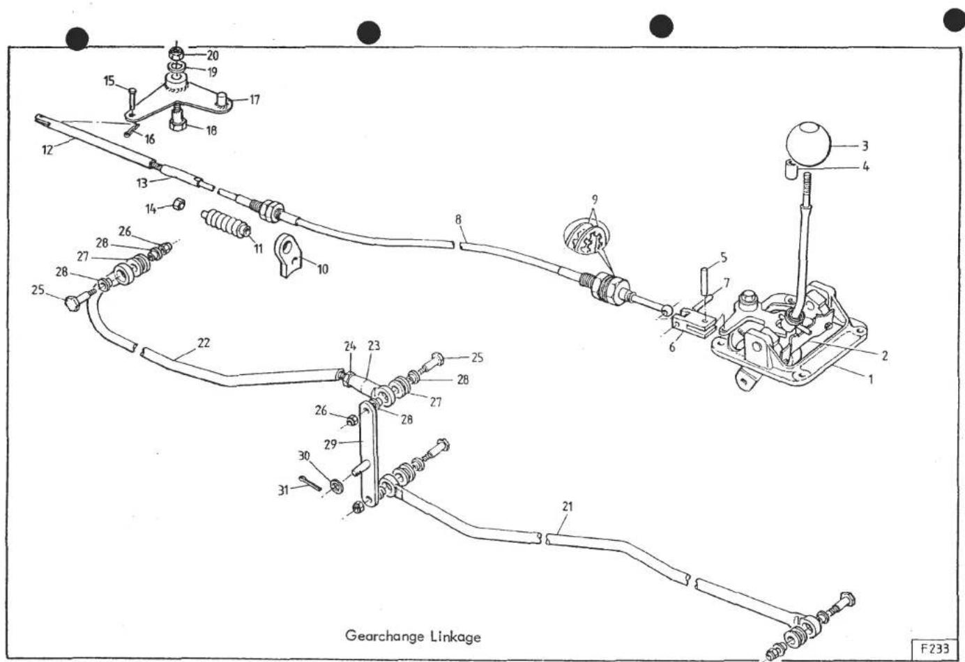
SECTION FB
Page 5
Key to Gearchange Linkage Drawing
- Gear Lever Assembly.
- Reverse Gate.
- Knob, Gearlever.
- Spacer, Gearlever Knob.
- Spirol Pin, Bellcrank to Yoke.
- Connector Yoke, Cable to Bellcrank.
- Spirol Pin, Cable to Yoke.
- Crossgate Cable.
- Washer, Shakeproof.
- Abutment Bracket, Rear.
- Dust Cover, Cable Rear.
- Rod, Crossgate Cable Extension.
- Locknut, Cable Stiffener.
- Locknut, Plain.
- Clevis Pin, Rod to Bellcrank.
-
Spring Clip, Clevis Pin.
-
Bellcrank Lever, Cross-shaft.
- Pivot Pin, Bellcrank.
- Washer, Pivot Pin.
- Nut, Nyloc, Pivot Pin.
- Tube, Gearchange, Front.
- Tube, Gearchange, Rear.
- Adjuster, Gearchange Tube.
- Locknut, Gearchange Adjuster.
- Pivot Pin, Gearchange Tubes.
- Nut, Pivot Pin.
- Bush, Rubber, Tube End.
- Bearing, Plastic, Tube End.
- Relay Lever.
- Washer, Relay Lever Pivot.
- Split Pin, Relay Lever Pivot.
Adjustment
Tube Linkage Basic Setting:
With the linkage connected, and the transmission in neutral, check the position of the relay lever on the RH engine mounting leg. The lever should be vertical, or leaning very slightly backwards at the top. If necessary, disconnect the rear tube from the relay lever, and adjust length to suit. Tighten the locknut after adjustment, but before reconnecting to relay lever, check that full travel of the gear lever both fore and aft provides movement at the relay lever exceeding that required by the rear tube for complete selection of gears.
Crossgate Cable Basic Setting:
The crossgate cable, outer casing should be fitted at its rear end into the clutch housing abutment with the adjustment at its mid position. Tighten the locknuts.
With the transmission in neutral and the cable connected, check the position of the gear lever. The lever should be vertical or leaning very slightly to the right. If necessary, disconnect the cable extension rod from the cross shaft bellcrank lever and after slackening the locknut, screw the extension rod on or off the cable to achieve the correct setting. Tighten locknut.
Before finally connecting extension rod to the bellcrank lever, check that full travel of the gear lever side to side provides movement of the extension rod exceeding that required by the bellcrank for full axial cross shaft movement.
NOTE: On cars up to 1983 fitted with a 240 mm crossgate cable extension rod, a special stiffening locknut (A082F4066F) may be fitted in place of the plain nut to increase stiffness of the crossgate cable.
Later cars, and Federal cars have a shorter crossgate cable and 442 mm extension rod.
FB.2. - TRANSMISSION ASSEMBLY
To Remove
- Remove engine compartment rear floor and chassis crossmember.
- Drain gearbox oil.
- Remove silencer。
- Disconnect drive shafts and remove adaptors and brake discs.
- Release brake caliper mounting bolts and support calipers clear.
- Support rear of gearbox and remove gearbox mounting brackets complete with rubber mountings.
- Disconnect the gearbox linkage from the gearbox and clutch housing.
- Remove the turbocharger oil drain pipe and boost sensing pipe. (Turbo only).
- Release the reverse light switch wires.
- Disconnect the speedo drive cable.
- Release the lower clutch housing to engine bolts.
- Remove the air pump (Federal cars).
- Release the Turbo air inlet hose and adaptor (Turbo only).
- Release the clutch slave cylinder.
-
Remove the starter motor.
-
Support the engine and release the remaining clutch housing to engine bolts. Carefully withdraw the gearbox assembly rearwards to disengage the clutch shaft and lift out.
To Replace
Reverse the removal procedure, noting the following:
a). (NOT Dry Sump Turbo) - Check underside of engine sump by clutch housing fixings for shim marking. '000' - no shim, '020' - one 0.020" shim, '040' - two 0.020" shims. These shims to be fitted between clutch housing and sump.
b). Adjust gearchange linkage as in FB.1.
c). Check/refill with gearbox oil as necessary.
d). Pump brake pedal to restore rear brake pad position.
SECTION FB
FB.3. - CLUTCH BELLHOUSING
To Remove
- Remove the transmission assembly and driveshaft bearing housing assemblies.
- From inside the bellhousing remove the four nuts and washers on the studs attached to the gearbox casting.
- Remove the ten bolts securing the outer edge of the gearbox casting to the bellhousing.
- Hold the differential in position against the bellhousing and pull away from the gearbox casting. Place the bellhousing on the bench with the differential uppermost and lift out the differential.
Dismantling
- Slide off the fork arm the rubber dust excluder.
- From inside the bellhousing remove the retaining spring and the thrust bearing assembly.
- Remove the pin securing the fork to the ball joint and withdraw the fork.
To Replace
- Reverse the dismantling and removal procedures for the clutch bellhousing. Seal the mating faces with "Silastic". Tighten all bolts to specified torque.
FB.4.- CLUTCH SHAFT
To Remove
- Remove the clutch bellhousing as previously described.
- Remove the tube enclosing the clutch shaft together with the two 'O' rings. The tube should pull out from the oil return flange, but may come away attached to the flange.
-
Remove the oil return flange.
-
Remove the circlip retaining the clutch shaft in the primary shaft. Take care not to lose the spring between the clutch shaft and primary shaft. If the circlip is very difficult to remove and further dismantling is intended, then remove clutch shaft complete with primary shaft. It will be easier to remove the circlip on the bench.
To Replace
- Reverse the removal procedure for the clutch shaft and clutch bellhousing.
Note: When replacing the release bearing guide tube, that the chamfered end is fitted towards the clutch housing.
- Remove the transmission unit as previously described.
- Remove the rear and top cover on the gearbox.
- Remove the bolt securing the 5th gear synchro assembly together with the deflector. To assist in the removal of the bolt, slacken the screws securing the reverse gear fork and engage two gears, e.g. 1st gear and reverse gear.
- Remove the locking wire through the screw securing the 5th gear fork and remove the screw.
- Remove the 5th gear synchro assembly and the 5th gear fork.
- Remove the speedometer driven gear and connection socket.
- Remove the eight screws securing the rear housing and withdraw the rear housing.
To Replace
- Reverse the removal procedure taking care to fix a locking wire to the 5th gear fork fixing screw. Tighten retaining bolt for the synchro assembly to 14.5-16.5 kgf.m (105-120 lbf.ft). Seal all mating faces with "Silastic".
FB.6.-GEAR SELECTORS REMOVAL
- Remove the transmission unit and gearbox rear housing as previously described. Remove the gearbox top cover together with the selector crossshaft.
Reverse Gear Selector
- Slacken the screws securing the fork (A) and the operating dog (B), first removing the locking wire, to the selector shaft.
- Withdraw the selector shaft, removing the fork, the operating dog and shaft locking ball and spring.
5th Gear Selector
- Slacken the screw securing the 5th gear operating dog (C), after removing the locking wire.

Fig.5 Gear selectors
- Remove the shaft, the operating dog and shaft locking ball and spring, and the small interlock plunger inside the front end of the shaft.
3rd and 4th Gear Selector
- Slacken the screw securing the fork (D) after removing the locking wire.
- Remove the shaft, the fork, the shaft locking ball and spring, and the small interlock plunger inside the front end of the shaft.
1st and 2nd Gear Selector
- Slacken the screws securing the fork (E).
- Remove the shaft and the shaft locking ball and spring; the fork cannot be removed at this stage.
Interlock plungers
To Remove
- Prise out the blanking plugs at positions (F) & (G) and pushout the interlock plungers, taking care to note the order and position of the plungers. NOTE: One long plunger between 3rd/4th and 5th selector shafts and shorter plungers between 1st/2nd and 3rd/4th selector shafts and 5th and reverse selector shafts.
FB.7. - GEAR SELECTOR REPLACEMENT
1st and 2nd Gear Selector
- Locate the locking ball and spring in position.
- Compress the spring and ball assembly, using a 6mm diameter rod.
- Insert the gear selector shaft through the gearbox outer casting, the operating fork and into the differential end of the gearbox casting up to the neutral position.
- Using a set of 1st and 2nd synchro gauges T000T0618 locate the fork in the neutral position. The sets of gauges are available in different thicknesses, select a set of gauges giving the least movement of the fork.
- Tighten the two screws securing the fork to a torque of 4kgf.m (29 lbf. ft) and remove the gauges.
3rd and 4th Gear Selector
- Place the first interlock plunger in from the opening at (F) figure 5 and locate in the 1st and 2nd selector shaft notch.
- Insert the gear selector shaft through the gearbox outer casting, fit locking ball and spring as previously described, the operating fork and into the differential end of the gearbox casting, taking care to correctly locate the small plunger inside the front end of the selector shaft.
- Locate the operating fork on the selector shaft so that the notch on the shaft lines up with the screw hole and screw down the grub screw, lock with wire.
5th Gear Selector
- Place the long interlock plunger in from the opening at (G) figure 5 and ensure that the fitted selector shafts are located in the 'neutral' position. This will allow the 5th gear selector shaft to be inserted into the differential end of the gearbox.
- Insert the gear selector shaft through the gearbox outer casting, fit the locking ball and spring as previously described, the 5th gear operating block and into the differential end of the gearbox casting, ensuring that the small interlock plunger is located inside the front end of the selector shaft.
- Locate the 5th gear operating block on the selector shaft so that the notch on the shaft lines up with the screw hole in the block. Screw down the grub screw and lock with wire.
Reverse Gear Selector
- Place the last interlock plunger in from the opening at (G) figure 5 and ensure that the fitted selector shafts are located in the 'neutral' position.
- Insert the gear selector shaft through the gearbox outer casting, fit the locking ball and spring as previously described, the operating dog, the reverse gear fork and into the differential end of the gearbox casting.
- Locate the reverse operating dog on the selector shaft so that the notch on the shaft lines up with the screw hole in the operating dog. Screw down the grub screw and lock with wire.
- Position the reverse selector shaft in the neutral position with the notch in the operating dog vertical. Place the gauge T000T0619 (3mm) against the 1st gear idler and move the reverse intermediate gear, together with the reverse

Gear Selector Mechanism
- Top Cover and Cross Shaft Bearing cap
- Dowel, Top Cover locating.
- Setscrew, Top Cover to Gearbox.
- Setscrew, Bearing Cap to Cover.
- Shouldered Stud.
- Washer.
- Filler Plug.
- Gasket Filler Plug
- Cross Shaft Spindle Assembly.
- 'O' Ring, Cross Shaft Spindle.
- Selector Shaft, reverse.
- Selector Shaft, 5th.
- Selector Shaft, 3rd and 4th.
-
Selector Shaft, 1st and 2nd.
-
Relay Dog, Reverse Selector Shaft.
- Selector Fork, reverse.
- Relay Dog, 5th Selector Shaft.
- Selector Fork, 5th.
- Selector Fork, 3rd and 4th.
- Selector Fork, 1st and 2nd.
- Locking Screw, Fork/Relay to Shaft.
- Setscrew, Fork Clamping.
- Interlock Plunger, short.
- Interlock Plunger, long.
- Blanking Plug, Interlock Bore.
- Detent Ball, Selector Shaft.
- Spring Detent Ball.
fork, up against the gauge. Tighten the two locking screws to a torque of 4 kgf.m (29 lbf.ft).
4th Gear Stop Adjustment
- Replace the 'Gearbox Rear Housing' as previously described.
- Engage the 4th gear.
- Gently push the slider against the fork. Measure the clearance 'Y' between the slider and the 4th gear pinion, using feeler gauges.
- Place a shim of thickness 'Y' +0.5 mm between the pinion and slider. Tighten the screw of the stop (J in fig.5) until it bears against the shaft of the 3rd and 4th gear fork.
- Tighten the locknut on the stop and check the clearance.
Interlock Plungers
To Replace
- Smear the bores of the interlock plungers with a sealing compound and knock in the blanking plugs at positions (F) and (G).
Final Assembly
- Fit top cover on the gearbox and replace the transmission unit as previously described.
FB.8.-PRIMARY SHAFT
To Remove
- Remove the Gear Selectors and the clutchshaft as previously described.
- Remove the speedometer drive wheel using spanner T000T0617 and pull the 5th gear driven pinion off the splined pinion shaft.
-
Release the forward bearing (bellhousing end) on the primary shaft by gently tapping the rear end of the primary shaft.
-
Release the rear bearing on the primary shaft using a puller if necessary. Take care not to lose the balls from the race.
NOTE: The inner bearing rings are in two halves on the primary shaft rear end and care should be taken to note where each is fitted.

Fig.7 Primary shaft assembly
- Move the primary shaft towards the bellhousing, separating the 4th gear drive pinion to gain access to the synchro hub assembly retaining circlip. Remove the circlip from the shaft using circlip pliers 3253-T, taking care to note the direction in which it is fitted.
- Move the pinion shaft towards the bellhousing as described under heading 'Bevel Pinion' and allow gears to rest in the bottom of the casing to provide additional space to withdraw the primary shaft.
- The primary shaft can now be moved towards the bellhousing end until the rear end of the shaft is clear of the casing. Lift out the primary shaft assembly.
- Remove the 1st and 2nd gear selector fork, (E) figure 5.
Dismantling
- Slide off the 4th gear drive pinion with the synchro ring and the needle bearing cage.
-
Remove the synchroniser.
-
Slide off the 3rd gear drive pinion with the synchro ring and the needle bearing cage.
- If the clutch shaft is fitted, remove the circlip securing the clutch shaft to the primary shaft and remove the clutch shaft and spring.
To Replace
- If the clutch shaft is disconnected, fit the spring (O), then the clutch shaft (M) and secure with the circlip (J).
- Fit the following onto the primary shaft in the order shown.
(a). 3rd drive gear (P) together with its needle bearing cage coated with transmission oil.
(b). Synchro ring (F).
(c). Synchroniser (E) ensuring that the collar with a groove is towards the 3rd drive gear (P).
(d). Using the circlip pliers T000T0620 fit the circlip (Q). Make sure circlip is fitted in the direction noted when removed.
IMPORTANT: The maximum movement of the synchroniser (E) on the shaft must not exceed 0.10 mm. Adjustment of this movement is achieved by changing the circlip (Q) for one of a different thickness.
(e). Synchro ring (D).
(f). 4th drive gear (R) together with its needle bearing cage coated with transmission oil. Slide the synchroniser (E) across to engage the 4th drive gear.
- Pass the input shaft end of the assembly through the top opening of the gearbox, then forward through the bearing opening into the differential compartment and locate circlip in its groove. It may be necessary to remove the pinion shaft to provide additional space to move the primary shaft down into the casing. See under heading 'Bevel Pinion Shaft'.
- Fit the double rear bearing (C) and the front bearing (H) using a tube 30 mm internal diameter, 300 mm long.
- Replace the bevel pinion, see 'Bevel pinion Shaft'.
- Place the reverse gear wheel down into the gearbox with the fork groove towards the differential. Insert the intermediate shaft and line up therecess in

Gearbox Shafts and Gears
Key to Gearbox Shafts & Gears Drawing
- Clutch Shaft.
- Spring, Clutch Shaft endthrust.
- Circlip, Clutch Shaft retention.
- Support Tube, Clutch Release Bearing.
- Sealing Ring, Support Tube.
- Scroll and Housing.
- Ball Bearing, Primary Shaft front
- Primary Shaft.
- 3rd Speed Drive Pinion.
- Needle Roller Bearing, 3rd Pinion.
- Syncroniser Assembly, 3rd and 4th.
- Syncroniser Ring, 3rd, 4th and 5th.
- Stop Ring, 3rd and 4th, Syncro.
- 4th Speed Drive Pinion.
- 5th Speed Drive Pinion.
- Needle Roller Bearing, 4th and 5th Pinion.
- Double Ball Bearing, Primary Shaft rear
- Syncroniser Assembly, 5th.
- Circlip, 5th synchroniser.
- Screw, 5th Hub to Primary Shaft.
- Roller Bearing, Secondary Shaft front.
- 1st Speed Driven Pinion.
- 2nd Speed Driven Pinion.
- Needle Roller Bearing.
- Sleeve, 1st/2nd Pinion Bearing.
- Syncroniser Assembly 1st/2nd.
- Syncroniser Ring, 1st and 2nd.
- Spacer Washer, Selective.
- 3rd and 4th Speed Driven Pinion.
- Double Ball Bearing, Secondary Shaft rear.
- 5th Speed Driven Pinion.
- Nut/Speedo Drive Gear.
- Reverse Idler Gear.
- Spindle, Reverse Idler Gear.
- Screw, Reverse Gear Spindle.
- Nut, reverse spindle screw.
the shaft with the grub screw. Smear the threads of the grub screw with a locking compound and tighten screw and lock with nut.
- Fit the 5th drive gear (S) together with its needle roller cage coated with transmission oil, synchroniser (B) and operating fork assembly on the primary shaft. Secure with the deflector (T) and bolt (A) and tighten to 14.5 - 16.5 kgf.m (105 - 119 lbf.ft).
FB.9.-BEVEL PINION SHAFT
To Remove
- Remove the Primary Shaft as previously described.
- Withdraw the bevel pinion through the gearbox casing into the differential housing.
- As the bevel pinion is drawn through the casing, remove the 3rd & 4th driven gear pair, adjusting washer, 1st and 2nd syncro hub assembly with gears and needle roller bearings.
NOTE: The two rear ball races and the inner bearing rings must be replaced in the same order, fix labels to indicate positions.

Fig.8 Bevel pinion assembly
SECTION FB
To Replace
- Check all parts are clean and there are no abrasive or metal particles adhering to the parts.
- Fit the front roller bearing (l) on the pinion (k) using a suitable length (240 mm) of tubing (inside diameter 44 mm). Make sure the washer (j) is fitted against the pinion before pressing on bearing.
- Feed the pinion shaft through the opening in the gearbox casing from the differential end.
- Onto the shaft inside the gearbox casting first place the 1st speed driven pinion (h), together with its needle bearing cage (m) and inner bearing sleeve (n). Coat the bearing before fitting with transmission oil.
- Next place onto the shaft the syncro ring (g), the synchroniser (f) with the reverse gear teeth towards the back of the gearbox and the syncro ring (e).
- Now slide on the 2nd speed driven pinion (d) together with its needle bearing cage (p) and inner bearing sleeve (o). Coat the bearing before fitting with transmission oil.
- Finally place on the shaft the adjusting washer (q) and the double pinion (r) and push the shaft to the rear of the gearbox.
- Fit the rear double bearing (c), taking care to assemble the double bearing races and bearingring in the original positions.
- Fit the 5th gear pinion (b) with the small shoulder on the pinion against the double bearing.
- Using spanner T000T0617, Lock the shaft and tighten the threaded speedometer drive wheel (A) to a torque of 20 to 22 kgf.m (145 to 160 lbf .ft). If both shafts are fitted, then the shafts can be locked by selecting the reverse gear and any other gear. Do not lock nut at this stage.
- Before fitting the primary shaft and covers to the gearbox, check the pinion cone setting as detailed in "Adjustments".
Adjustments
On the ground face of the bevel pinion is engraved a figure in millimetres. This figure represents the distance, which must be maintained after adjustment, between the differential centre line and the ground face of the bevel pinion.
This distance is different for each bevel pinion and is checked using the distance gauge fixture T000T0616 fitted with dial gauge T000T0615. The fixture is designed so that the distance between the centre line of the ground contact faces (drive shaft bearing surfaces) and the faces of the probes is 60 mm. This figure is engraved on the fixture between the probes.
- First calibrate the fixture.
(a). Clean the bearing surfaces and the ground contact faces of the fixing.
(b). Place the fixture on a surface plate.
(c). Zero the dial gauge with the large needle on 0.
(d). Note the position of the totalising needle.
Totalising needle between 4 and 5.
Large needle at 0.
- Offer the fixture up to the bearing surfaces of the drive shafts with the dial gauge stem not in contact with the ground face of the bevel pinion, unlock the gauge stem.
- Rotate the fixture in the bearing surfaces, so the gauge stem passes over the ground face of the pinion, until the large needle of the dial gauge is about to change direction. Lock the needle positions and note the readings.
Example: Totalising needle between 0 and 1.
Large needle at 86.
- Remove the fixture and place once again on the surface plate. Allow the dial gauge stem to return slowly, so the full revolutions can be counted.
When the gauge stem comes to rest on the surface plate the measurement of the part revolution can be made.
If the measurements for the examples are:
Conic distance 60 + 3.86 = 63.86 mm.
- If the dimension engraved on the pinion for this example is 63.95 mm then the bevel pinion must be moved away from the differential centre line by:
6 3. 9 5 - 6 3. 8 6 = 0. 0 9 mm.
- To adjust the bevel pinion remove the rear housing, the speedometer drive wheel and the 5th gear pinion.
-
Remove the bevel pinion as previously described.
-
Measure the thickness of the adjusting washer (q) figure 8 which for this example is: 2.81 mm. Replace this washer by another with a thickness calculated in the following manner:
2. 8 1 - 0. 0 9 = 2. 7 2 mm
As washers are available in thickness from 1.65 mm to 3.13 mm in steps of 0.04 mm, the nearest to the calculated thickness is 2.73 mm.
-
Fit the new adjusting washer (q) and replace the bevel pinion as previously described.
-
Check the adjustment, repeat instructions 1 to 4.
-
If adjustment is within the tolerance ± 0.02 mm fit the 1st and 2nd gear operating fork.
Final Replacement
- Replace the primary shaft as previously described, tighten speedometer drive wheel nut to specified torque as described in "bevel pinion shaft" and lock nut by peening it to the pinion.
- Check that the pinions rotate freely when out of gear.
- Apply sealing compound to cover mating surfaces and tighten all securing screws to the torque specified in the TECHNICAL DATA.
FB.10.- DIFFERENTIAL SHAFTS (Drive Shafts)
Dismantle
- Remove and dismantle the 'Clutch Bellhousing' as previously described.
- Remove the grub screw securing the large nut which locks the bearing to the shaft.
- Using the box spanner T000T0612 unscrew and remove the large nut.
- Drive the shaft out through the bearing.
- Remove the grub screw in the top of the shaft housing and using the special spanner T000T0613, remove the locking ring securing the bearing to the shaft housing.
- Gently tap out the two ball races.
NOTE: The two ball races must be replaced in the same order, fix labels to indicate positions.
-
Drive out the double ball bearing outer ring using a tube of 65 mm external diameter.
-
Using a suitable extractor, draw the inner bearing rings from the shaft. Note positions.
-
Remove the sealing ring from the shaft housing.
-
Remove the oil retaining washer and bearing distance bush assembly from the shaft.
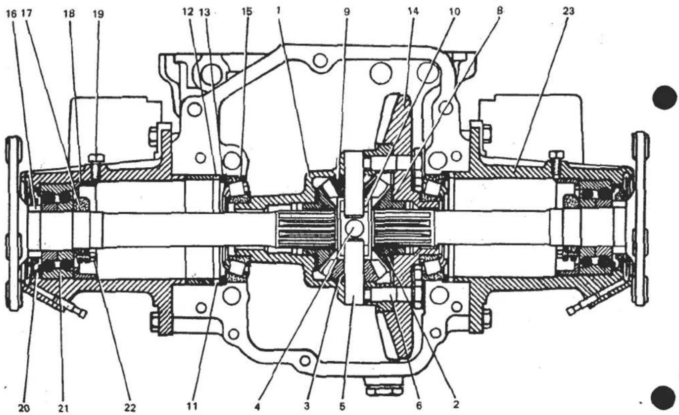
Fig.9 Differential assembly
-
Satellite housing
-
Planet wheel
-
Satellite gear
-
Satellite spindle, long
-
Satellite spindle, short
-
Screw with dowel
-
Crown wheel screw
-
Planet wheel washer
-
Satellite gear washer
-
Crosshead bush
-
Distance piece
-
Distance washer
-
Adjusting washer
-
Crown wheel
-
Roller bearing
-
Spacer
-
Locking nut
-
Nut
-
Grub screw
-
Oil seal
-
Bearing
-
Grub Screw
-
Output shaft housing

To Assemble
NOTE: The differential drive shaft on the left-hand side of gearbox is the shorter.
- Fit the bearing (21) in the housing and tighten the nut (18) to 10 kgf.m (72 lbf.ft) using the spanner T000T0612. Lock the nut using the grub screw (19).
- Fit the oil seal (20) using a suitable tool.
- Position the oil retaining washer on the shaft. Fit the spacer (16), and ensuring that the washer is centralised, press on the spacer.
- Fit the differential shaft into the housing and position using a tube of 30 mm inside diameter under a press. Tighten the bearing locking nut (17) to 15 kgf.m (108 lbf.ft). Tighten the grub screw (22) in the locking nut.
- Assemble and replace the 'Clutch Bellhousing' as previously described.
FB.11.- DIFFERENTIAL CROWNWHEEL & PINION
To Remove
- Dismantle the 'Differential Shafts' as previously described.
- Using a suitable extractor remove the tapered roller bearings from each end of the crown wheel assembly.
- Remove the eight screws (6) securing the crown wheel to the housing and remove the following:
(a) Crown wheel (14)
(b) Satellite spindle (4)
(c) Planet wheel (2) and thrust washer (8)
(d) Two satellitespindles (5)
(e) Satellite gears (3) and stop washers (9)
(f) Crosshead (10)
(g) Other planet wheel and thrust washer.
To Replace
- Place in the satellite housing a thrust washer (8), one planet wheel (2), one fixed thrust washer (9), one satellite gear (3) and the long spindle (4).
- Rotate the planet wheel and check that the point of minimum clearance is
0.1 mm. If this is not so replace thrust washers until the minimum clearance is achieved. Remove the satellite and thrust washer making a note of the position in the housing.
- Repeat 1 and 2 for each satellite gear, taking care to fit the crosshead bush (10) to support the short satellite spindles (5). Fit the dowel pin screws temporarily to locate the short satellite spindles.
- Fit all the satellite gears and thrust washers.
- Place the second planet wheel with thrust washer in the crown wheel.
- Locate the satellite housing in recess in the crown wheel and fit the eight screws. Take care the dowel screws are fitted in the correct holes. Gradually tighten the screws, checking the pinions rotate freely, to a torque of 11.5 to 13 kgf.m (83 to 94 lbf.ft).
- Check the minimum clearance of the second planet wheel and this should be 0.1 mm. Change the thrust washer to achieve this clearance.
- Using an oil gun, inject gearbox oil into the satellite housing lubricating all parts inside.
- Fit the bearings on the satellite housing and crown wheel using a suitable mandrel.
FB.12.- DIFFERENTIAL BEARINGS ADJUSTMENT
There are two methods by which adjustments can be made to the differential bearings. The first method uses a dial gauge to measure the thickness of the adjusting washers, which is directly related to the bearing stress. The second method measures the torque required to rotate the differential using a spring balance.
Method 1
- Position the differential and bearings.
(a) Place the differential together with bearings in the end of the gearbox casing.
(b) Place the adjusting washer (13) and the distance washer (12), with a total thickness of 7 mm, against the left-hand differential bearing.
(c) Secure the differential in place using clamps as necessary.
(d) Place a new paper gasket on the left-hand differential shaft housing,
SECTION FB
locate the drive shaft in the planet wheel and align the screw holes. Fit screws, taking care to fit the correct lengths and tighten.
(e) Place the gearbox casting on its left-hand side, supporting it in this position.
(f) Place against the right-hand differential bearing the adjusting washer (13) followed by the distance washer (12) and the distance piece (11). The total thickness (12) and (13) should not be less than 9 mm.
(g) Locate the right-hand differential drive shaft in the planet wheel and align the screw holes. Without a gasket fitted on housing, fit the assembly in position and tap lightly on the differential shaft.
(h) Remove the right-hand drive shaft, adjusting washers and distance piece.
- Adjust the pre-load on the differential bearings.
NOTE: The bearings must be fitted with a specified pre-load.
(a) Place gauge support T000T0614, fitted with dial gauge T000T0615, on the collar of the right-hand drive shaft housing. Allow the probe of the gauge to touch the bearing face of the housing. Bring the zero of the movable dial of the gauge in line with the large needle. Note the position of the needle.
Example: Large needle reading = 0
Small needle reading = 0
(b) Place the dial gauge and support on the gearbox casting with the probe bearing on the distance piece. Take two measurements.
Example: Measurement A amp; = amp; 7. 7 6 mm Measurement B amp; = amp; 7. 8 0 mm Average A and B amp; = amp; 7 . 7 6 + 7 . 8 0/2 = 7. 7 8 mm
(c) Add to the average measurements the following items:
Thickness of the seal = 0. 1 0 mm
Stress on the bearing = 0. 3 0 mm
Total = 0. 4 0 mm
Example: 7.78 + 0.40 = 8.18 mm
Select an adjusting washer and a distance washer with a total thickness nearest to the calculated thickness. This would be for the example
used 8.20 mm (the adjusting washer has a smaller inside diameter).
(d) Place the selected washers on the right-hand bearing, with the adjusting washer next to the bearing. Fit the distance piece and fit the right-hand drive shaft housing with a paper gasket between the mating surfaces.
IMPORTANT: The thickness of the washers fitted against the left-hand and right-hand bearings corresponds to the setting of the bearing stress only.
To adjust the backlash these washers must be redistributed to the left and to the right, without changing the overall thickness.
Right - hand bearing washers = 8. 2 0 mm Overall thickness = 1 5. 2 0 mm
Example: Left-hand bearing washers = 7.00 mm
Method 2
- Fitting the differential assembly.
(a) Place the differential, fitted with bearings, in the end of the gearbox casting.
(b) Secure the differential in place using clamps as necessary.
(c) Place new paper gaskets on the left-hand and right-hand drive shafts assemblies, together with any shims removed during dismantling. Locate the drive shafts in the planet wheel and align the screw holes. Fit screws, taking care to fit the correct lengths and tighten.
- Adjust the pre-load on the bearings.
NOTE: The bearings must be fitted with a specific pre-load. This can be checked by measuring the torque required to turn the differential.
(a) To measure the torque fix and wind a length of cord around the differential satellite housing. Attach to the free end of the cord to a spring balance so the satellite housing can be rotated when the spring balance is pulled.
(b) Take a reading from the balance when the satellite housing is just about to rotate. This reading should be within the following limits
given for bearings which have previously been used and new bearings.
(i) Bearings previously used should be within 4 to 6 kg. If the reading is less than 4 kg, increase the thickness of the adjusting washers. For readings in excess of 6 kg reduce the thickness of the adjusting washers.
(ii) New bearings should be within 6 to 9 kg. If the reading is less than 6 kg, increase the thickness of the adjusting washers. For readings in excess of 9 kg reduce the thickness of the adjusting washers.
NOTE: An adjusting washer 0.10 mm thick corresponds approximately to a bearing stress of: 0.250 kg for new bearings 0.500 kg for used bearings
IMPORTANT: The thickness of the washers fitted against the left-hand and right-hand bearings corresponds to the setting of the bearing stress only.
To adjust the backlash these washers must be redistributed to the left and right, without changing the overall thickness.
FB.13. - BACKLASH ADJUSTMENT
To check the backlash adjustment both drive shaft housings must be fitted.
- Measure the clearance between the crown wheel and pinion teeth i.e. backlash.
(a) Fit a dial gauge T000T0615 to a support, fixed to the gearbox casting.
(b) Adjust the position of the dial gauge so that the measuring probe touches the flank of a tooth at heel (outer edge of crown wheel) see figure 10. This should be achieved somewhere near maximum diameter of the crown wheel.
(c) Move the crown wheel to the extent of the backlash several times and measure the difference on the dial gauge.

Fig.10 Measuring crown wheel backlash
(d) Repeat the procedure on teeth at about 90° , 180° and 270° around the crown wheel from the first measurement. The difference between any two measurements should not exceed 0.10 mm. If a reading exceeds this figure it will indicate the crown wheel is running out of true or is badly fitted.
(e) Make a note of the minimum clearance.
Example clearance = 0.73 mm
- Adjust the backlash.
IMPORTANT: The clearance between the teeth is adjusted by redistributing the adjusting washers against the left-hand and right-hand bearings. Under no circumstances must the overall thickness of the washers be altered, see DIFFERENTIAL BEARINGS ADJUSTMENT.
(a) The clearance must be adjusted to within the limits 0.16 mm and 0.24 mm. Aim for an average clearance of 0.20 mm.
(b) Subtract this average clearance from the minimum reading noted; for the example given, this will be:
0. 7 3 - 0. 2 0 = 0. 5 3 mm
therefore, for this example the clearance must be reduced by 0.53 mm.
NOTE: Moving a 0.15 mm adjusting washer from one side to the other, will change the clearance by 0.10 mm.
For the example therefore, the thickness of the washers to be moved
0 . 5 3 × 0 . 1 5/0 . 1 0 = 0. 7 9 mm
(c) In the example chosen, it is necessary to move the crown wheel towards the pinion by a distance of 0.79 mm.
To achieve this, the thickness of the washers against the right-hand bearing should be reduced to:
8. 2 0 = 0. 7 9 = 7. 4 1 mm,
and the thickness of the washers against the left-hand bearing should be increased by the same amount.
7. 0 0 + 0. 7 9 = 7. 7 9 mm
(d) Recheck the backlash measurement to verify that the difference between any two measurements, around the crown wheel, does not exceed 0.10 mm.
- If backlash is within the tolerance, assemble the differential assembly, replace the Clutch Bellhousing and refit Transmission Unit.
STEERING
SECTION HB - ESPRIT '88 M.Y. Onwards
| Sub-Section | Page | |
| General Description | HB.1 | 5 |
| Steering Wheel | HB.2 | 6 |
| Upper Steering Column Assembly | HB.3 | 8 |
| Intermediate Steering Column Assembly | HB.4 | 15 |
| Track Rod Ends & Toe-in Adjustment | HB.5 | 19 |
| Steering Rack Gaiters | HB.6 | 20 |
| Rack & Pinion Assembly | HB.7 | 21 |
NON-S.I.R. TYPE UPPER STEERING COLUMN

-
Steering wheel boss
-
Collets, boss to column
-
Rubber band, collet retention
-
Nut, steering wheel/boss retention
-
Washer, wheel/boss retention
-
Steering wheel
-
Countersunk screw, wheel to hub
-
Trim pad, steering wheel centre
-
Steering column assembly
-
Fixing, column to scuttle beam
-
'Break out' insert
-
Clamp bracket, column to pedal box
-
Fixing, bracket to pedal box
-
Sealing gasket, column to bulkhead
-
Seal plate
-
Fixings, seal plate
-
Steering lock
-
Shear bolt, steering lock fixing


S.I.R. TYPE UPPER STEERING COLUMN
- Upper column assembly
- 'Break out' insert
- Fixing to scuttle beam
- Fixing to pedal box
- Top bearing housing
- Fixing, housing to column
- Ball bearing, column top
- Circlip, top bearing
- Cushion ring
- Circlip, cushion ring
- Column lock
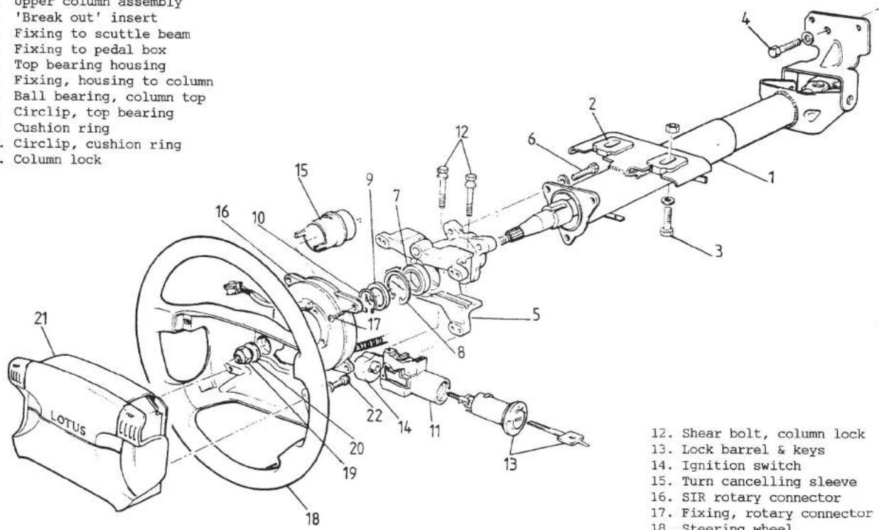
- Shear bolt, column lock
- Lock barrel & keys
- Ignition switch
- Turn cancelling sleeve
- SIR rotary connector
- Fixing, rotary connector
- Steering wheel
- Nut, wheel to column
- Washer, wheel to column
- SIR inflator module
- Fixing, inflator module
Page 4
INTERMEDIATE COLUMN & RACK & PINION ASSEMBLY


Key to Intermediate Column & Rack & Pinion Assembly Drawing
- Rack & Pinion assembly
- Gaiter (supplied as kit of 2 gaiters with clips)
- Track rod end
- Locknut, track rod end
- Rack assembly LH rubber mounting
- Clamp bracket, LH mounting
- Rack assembly RH rubber mounting
- Clamp bracket, RH rubber mounting
- Tapping plate, rack assy mounting
-
Spacer tube, lower u/j
-
Circlip, spacer tube stop
- Clip, spacer tube fix
- Lower universal joint (u/j)
- Pinch bolt, lower u/j
- Non-SIR intermediate shaft
- SIR lower intermediate shaft
- Steady bracket, int. shaft
- Bush, steady bracket
- Shim (if fitted), steady bracket
- Fixing, steady bracket
- SIR upper intermediate shaft
HB.1 - GENERAL DESCRIPTION
A rack and pinion steering system is used on the Esprit, with the steering rack assembly clamped to the chassis front crossmember behind the front axle line. On cars without a Supplementary Inflatable Restraint (S.I.R.), the collapsible upper steering column assembly is connected with the rack pinion shaft via a short intermediate shaft and two universal joints.
Non-S.I.R. Type Steering System

On S.I.R. equipped cars, a shorter upper column assembly requires two short intermediate shafts, the lower of which is supported in a chassis mounted bearing, and three universal joints to connect with the rack assembly.
S.I.R. Type Steering System

HB.2 - STEERING WHEEL
On non-S.I.R. (Supplementary Inflatable Restraint) cars, the three spoke steering wheel is secured to an alloy hub by six countersunk screws. The hub is splined to the inner steering column, and a tongue on the back of the boss serves to operate the cancelling mechanism for the turn indicator switch.
On S.I.R. equipped cars (primarily USA), the the steering wheel and hub are integrated into a single unit which houses an inflator module (air bag) at its centre, concealed beneath a moulded trim cover. The padded cover is designed to split open when the inflator module is deployed (air bag inflated). The spokes of the steering wheel also incorporate a pair of horn buttons.
WARNING: Any work on, or removal of the steering wheel on S.I.R. cars requires that rigorous safety precautions be taken in order to safeguard against unintentional deployment of the inflator module. Do not attempt any work on the steering wheel of an S.I.R. equipped car without referring to Sub-Section WA.3 - J in the separate manual 'Section WA', part no. E082T0327J.
To Remove Wheel & Hub Assy.: Non-S.I.R. Cars
- Pull off the trim pad from the centre of the wheel.
- Remove the nut and washer retaining the wheel.
- Match mark the relative positions of the steering wheel hub and inner column.
- Pull the wheel off the column using minimum force, if necessary using a suitable puller. DO NOT apply excessive axial force to the steering wheel, or inner or outer columns without the use of a puller, or the mechanism retaining the telescopic length of the column may be overridden, necessitating column replacement.
- Take care not to misplace the split thrust collar from the top of the column.

To Refit Wheel & Hub Assy.: Non-S.I.R. Cars
- Apply a small amount of PBC grease to the column splines to aid subsequent steering wheel removal, but ensure that the threaded section is thoroughly degreased;
- Check that the split thrust collar is held in position (by a rubber band) in the groove in the column just below the splines, with the tapered faces towards the steering wheel as shown;
- Taking care not to damage the turn indicator switch cancelling fingers, refit the steering wheel assembly with the match marks aligned, fit the washer and retaining nut and tighten to 41 - 47 Nm (30 - 35 lbf.ft).
To Remove & Refit Wheel & Hub Assy.: S.I.R. Cars
See Sub-Section WA.3 - J in separate manual 'Section WA' part no. E082T0327J.
Steering Wheel Alignment
If the steering wheel alignment requires re-setting, or if there are no wheel to column reference marks available when fitting a steering wheel, proceed as follows:
-
In order to maintain the required bump steer characteristic, it is important to ensure that the steering rack is centralised in the straight ahead position, i.e. both track rods are the same length. Measure the amount of visible thread at each track rod, and if necessary equalise by adjusting an equal and opposite amount at each side.
-
Slide the steering wheel onto the column splines in an approximate straight ahead position. Rotate the wheel to full left hand lock and then to right hand lock, and check that the two extreme steering wheel positions are the mirror image of each other. If necessary, reposition the wheel on the column until this is achieved. Fit and tighten the steering wheel nut as above.
Typical 'full lock' steering wheel positions

-
Road test the car to check steering wheel alignment. It should not be necessary to reposition the wheel by more than one spline to achieve alignment to within 5°. Complete alignment is achieved by adjustment at the track rod ends, an equal and opposite amount at each side to maintain the toe-in setting.
-
Check front wheel toe-in.
HB.3 - UPPER STEERING COLUMN ASSEMBLY
On non-S.I.R. (Supplementary Inflatable Restraint) cars, the upper steering column assembly comprises inner and outer columns, both of which are telescopically collapsible if an axial load above a specified figure is applied to the column in the course of an accident. The lower end of the outer column is secured to the pedal box via a clamp bracket, and the top end of the column is secured to the scuttle beam via two fixing bolts and 'break out' inserts, which are retained in slots in the column brackets by nylon pins. These pins are designed to shear in an accident, and allow the upper half of the column to break free of the scuttle beam and telescope downwards, this movement being accommodated by the deformation of an open mesh crumple section (covered by a rubber sleeve) at the bottom of the column.
The telescopic inner column assembly is supported in ball bearings and provided with splines at the top end for the steering wheel, and splines at the bottom end for connection with the intermediate column. The upper part of the
inner column is provided with a slot into which the steering lock engages.
On S.I.R. equipped cars (primarily USA), a different column is used, but the same principles apply. The same 'break out' fixings are used at the scuttle beam, but the lower end of the column is secured to the pedal box via a hinge bracket and a single fixing bolt. The two parts of the outer column are connected by grip collars and the assembly must be replaced if collapsed. The two parts of the inner column are connected by a telescopic joint, the length of which is fixed by plastic buttons locating in grooves, which may be overridden by a specified force. The assembly must be replaced if collapsed.
WARNING: Any work on, or removal of the steering column on S.I.R. cars requires that rigorous safety precautions be taken in order to safeguard against unintentional deployment of the inflator module. Do not attempt any work on the steering column of an S.I.R. equipped car without referring to Sub-Section WA.3 - L in the separate manual 'Section WA', part no. E082T0327J.
Post Accident Inspection
If the vehicle has been involved in an accident, or if there is any other reason to suspect that the upper column assembly may have collapsed, carry out the following inspection:
Non-S.I.R. Cars: Remove the steering wheel (see above), remove the column shrouds, and separate the lower end of the column from the intermediate shaft universal joint.
i) Loosen the column to scuttle beam fixing bolts and check that the two alloy 'break out' inserts are securely attached to the column flange.
ii) Measure the overall length of the inner column as shown in the diagram.
Specification = 758.5 - 759.5 mm
Replace the column if outside specification.
iii) Measure the overall length of the outer column tube, excluding the bearing housing flanges as shown in the diagram.
Specification = 611 - 612 mm
Replace the column if outside specification.
iv) If there is any discernible axial play in the column (along the direction of the column), the inner column telescopic retention mechanism has been overridden, and the column assembly should be replaced.
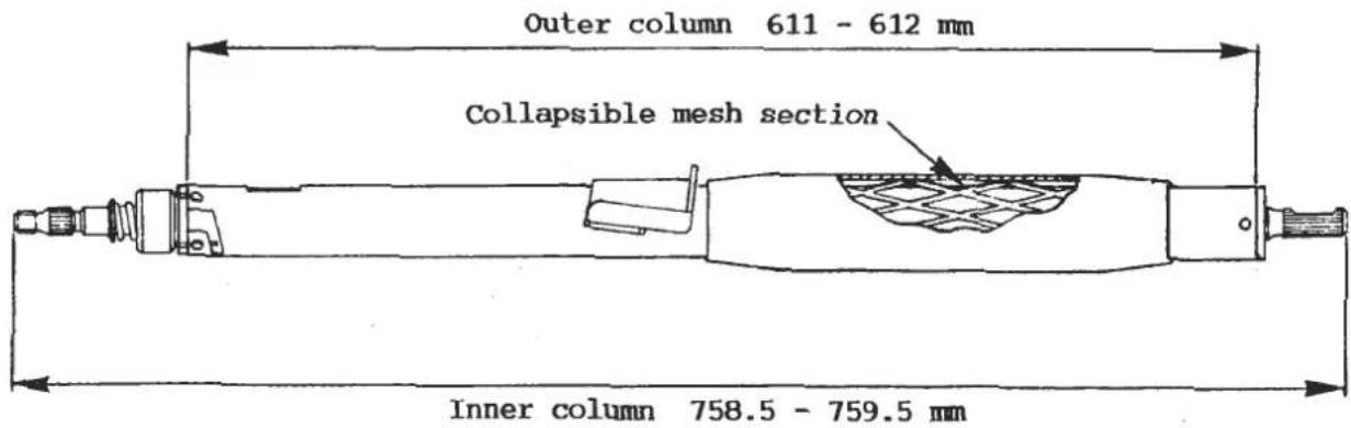
S.I.R. Cars:
i) Remove the column shrouds, loosen the column to scuttle beam fixing bolts and check that the two alloy 'break out' inserts are securely attached to the column flange.
ii) Check that the centreline of the u/j at the lower end of the column is within 3 mm of the pivot point of the outer column lower bracket. If greater than 3 mm, replace the column assembly.
iii) Measure the length of the lower part of the outer column as shown in the diagram.
Specification = 105.4 ± 1 mm If outside specification, replace the column assembly.

iv) If there is any discernible axial play in the column (along the direction of the column), the inner column telescopic retention mechanism has been overridden, and the column assembly should be replaced.
To Remove Upper Steering Column Assembly: Non-S.I.R. cars
-
Remove the steering wheel (see Sub-Section HB.2).
-
Remove the column shrouds: Release the two screws at each side, securing the upper to the lower shroud. Release the single screw and washer from beneath, securing the lower shroud to the column lock.
-
Remove the column switches: From beneath the fascia, disconnect the column switch and ignition switch connector blocks, and all tie wraps securing wiring and heater ducting to the column. Release the two screws securing the wiper control switch and remove both column switch assemblies. Slide off the switch spacer ring from the column.
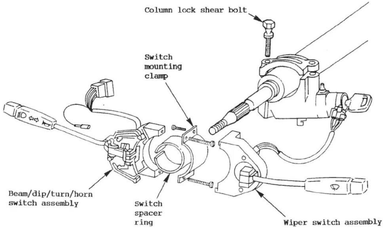
- From within the footwell, remove the pinch bolt securing the universal joint to the bottom of the upper column assembly.
- Slacken the clamp securing the column assembly lower end to the pedal box, and remove the two M10 bolts fixing the column upper end to the scuttle beam. Withdraw the complete column assembly through the fascia.
- Carefully drill out the shear bolt heads securing the column lock assembly to the column and remove the lock. Remove and discard the shear bolt threads.
To Refit Upper Steering Column Assembly: Non-S.I.R. cars
- Feed the column through the fascia and into the pedal box clamp bracket and intermediate column upper u/j. Take care to align the flat on the column with the pinch bolt hole in the u/j. Ensure that only a minimal amount of shaft is allowed to protrude through the joint yoke as shown in the diagram. Fit and tighten the pinch bolt using a new M8 'P' type Nyloc nut (A907E6284F) to 22 - 27 Nm (16 - 20 lbf.ft).

- Fit the upper end of the column to the scuttle beam using the two M10 bolts with new shakeproof washers A075W4049Z and existing flat washers. Finger tighten.
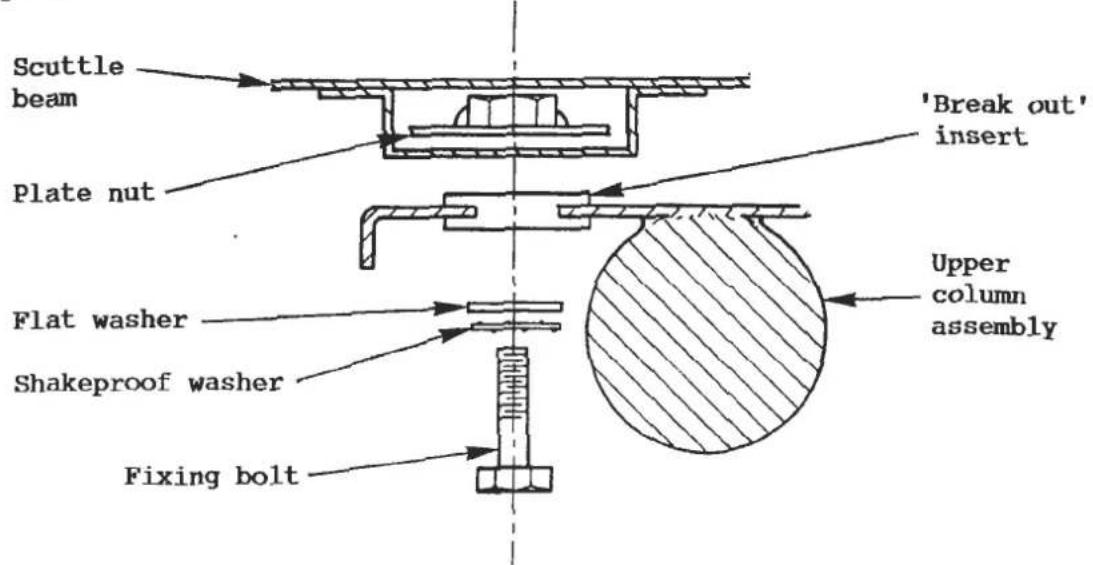
- Tighten the lower clamp bracket to the column, to 11 - 16 Nm (8 - 12 lbf.ft) before tightening the upper bolts to the scuttle beam to 28 - 30 Nm (20 - 22 lbf.ft).
- Fit the steering column lock/ignition switch assembly to the column using new shear bolts A079H6008F and tighten until sheared.
- Fit the switch spacer ring to the top of the column with the split on the left hand side, and clamp the two column switches into position with the pip on the indicator switch located in the spacer ring slot. Mate the connector blocks from the column switches and ignition switch, and fit tie wraps as necessary to secure harnesses and heater ducting to the column.
- Fit the column lower shroud with screw and washer to the column lock, and then the upper shroud with its four screws.
- Refit the steering wheel (see Sub-Section HB.2).
To Remove Upper Steering Column Assembly: S.I.R. Cars
WARNING: Any work on, or removal of the steering column on S.I.R. cars requires that rigorous safety precautions be taken in order to safeguard against unintentional deployment of the inflator module. Do not attempt any work on the steering column of an S.I.R. equipped car without referring to Sub-Section WA.3 - L in the separate manual 'Section WA', part no. E082T0327J.
-
Refer to separate manual 'Section WA' to:
-
remove the inflator module (Sub-Section WA.3 - I)
- remove the steering wheel (Sub-Section WA.3 - J)
- remove the rotary connector (Sub-Section WA.3 - K)
-
remove the knee bolster (Sub-Secion WA.3 - C)
-
Unplug the block connectors and release the harnesses for the column switches. Depress the retaining prongs, and slide out the column switches
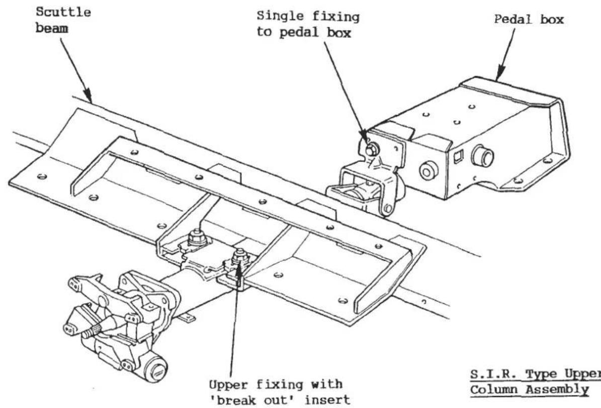

from the column top bearing carrier. Release the small grub screw at the bottom left hand rear of the steering lock body, and pull out the ignition switch.
- If necessary, remove the steering lock mechanism either by unscrewing the two shear bolts using a hammer and punch, or by drilling out the bolt heads.
- Remove the pinch bolt from the u/j at the bottom end of the steering column, and remove the bolt securing the column lower mounting bracket to the pedal box.
- Remove the two nuts and bolts securing the top end of the column to the scuttle beam, and withdraw the column assembly from the upper intermediate shaft.
- If necessary, the column assembly may be dismantled:
- Remove the circlip from the top end of the column, followed by the cushion ring, and withdraw the inner column from the bottom end of the outer column.
- If necessary, remove the three bolts securing the top bearing housing to the outer column. Remove the circlip, and press out the ball bearing assembly.
To Refit Upper Steering Column Assembly: S.I.R. cars
-
If necessary, reassemble the column assembly:
-
Fit the ball bearing into the top bearing housing using a press, and fit the retaining circlip. Fit the bearing housing to the top of the column, and retain with the three M6 setscrews and spring washers. Tighten the three screws.
-
Fit the inner column into the outer, and fit the cushion ring over the top end, followed by the retaining circlip.
-
Fit the upper column assembly into position.
-
Engage the upper intermediate shaft into the upper column u/j, with the flat on the shaft aligned with the pinch bolt hole. Fit the spring washer to the special M10 pinch bolt, and thread into the upper u/j but do not tighten at this stage.
- Two variations of scuttle beam mounting platform have been used:
Early Cars

Later Cars

On early cars, the column must be passed beneath the scuttle beam before pulling back onto the scuttle beam platforms. Fit the spacer washers between column flange and beam, and retain with fixings shown but do not tighten.
On later cars, the scuttle beam incorporates two weld studs onto which the upper column flange is fitted from beneath and retained with washers and Nyloc nuts. Do not tighten.
-
Secure the column assembly lower bracket to the pedal box with the single M8 bolt with shakeproof and flat washer.
-
Tighten the steering column fixings in the following order:
-
column to pedal box; 24 Nm (17.5 lbf.ft).
- column to scuttle beam (2 off); 15 Nm (11 lbf.ft).
-
upper column u/j to upper intermediate shaft; 40 Nm (30 lbf.ft).
-
Fit the steering lock to the top bearing housing using new shear bolts, and tighten until the bolt heads shear.
-
Fit the ignition switch and retain with the grub screw. Slide the two column switches into the column top bearing carrier and plug in their block connectors.
-
Refer to separate manual 'Section WA' (E082T0327J) to:
-
refit the knee bolster (Sub-Secion WA.3 - C)
- refit the rotary connector (Sub-Section WA.3 - K)
- refit the steering wheel (Sub-Section WA.3 - J)
- refit the inflator module (Sub-Section WA.3 - I)
HB.4 - INTERMEDIATE STEERING COLUMN ASSEMBLY
On non-S.I.R. cars, a single intermediate column is used together with two universal joints to transmit the motion of the upper steering column to the steering rack pinion shaft. When refitting the intermediate column, it is most important that the two joints are correctly phased with respect to each other.
On cars fitted with S.I.R. (Supplementary Inflatable Restraint), the shorter upper steering column assembly necessitates the use of two intermediate columns and three universal joints, with the lower intermediate column supported in a chassis mounted bearing. The design of the intermediate column system is such as to permit assembly only with the correct phasing of the three universal joints.
To Remove Intermediate Steering Column Assembly: Non-S.I.R. cars
-
Remove the pinch bolt securing the upper u/j to the upper column.
-
Remove the two nuts and bolts securing the upper column assembly to the scuttle beam, and slacken the clamp bolt securing the lower end of the column to the pedal box. Draw the upper column assembly into the car only sufficiently to disengage the inner column from the upper u/j.
-
From beneath the car, remove the pinch bolt securing the lower u/j to the intermediate column and withdraw the intermediate column into the car.
-
If necessary, remove the pinch bolt securing the lower u/j to the steering rack pinion shaft, and remove the lower u/j.
To Refit Intermediate Steering Column Assembly: Non-S.I.R. cars
When refitting the intermediate column, it is most important to follow the correct procedure to 'phase' the upper and lower u/js i.e. orientate the two joints in a particular manner with respect to each other. This setting provides the optimum steering 'feel', with minimum cyclical force variation as the wheel is turned.
- In order to ensure that the lower u/j is not slid too far onto the pinion shaft, with the consequent danger of the shaft end fouling the u/j spider, or of the u/j fouling the chassis, a circlip is fitted onto the pinion shaft followed by a rubber spacer tube.
Align the pinch bolt hole in the lower u/j with the flat on the pinion shaft and fit the u/j onto the shaft to abut the spacer tube, or until the shaft end is flush with the inside of the u/j yoke. Fit the pinch bolt and tighten to 22 - 27 Nm (16 - 20 lbf.ft). - From inside the car, feed the intermediate column through the bulkhead seal (but not into the lower u/j) before sliding onto the (unfixed) upper column assembly, with the pinch bolt hole aligned with the column flat. Fit the pinch bolt but do not tighten at this stage.
- Turn the front wheels until the axis of the pinch bolt hole in the upper part of the lower u/j is in a vertical fore/aft plane as shown in the diagram.
- Turn the steering wheel until the pinch bolt securing the upper column to the upper u/j is horizontal, and the upper and lower u/js are aligned 'back to back' as shown.

- From this position, turn the steering wheel 30° (3 splines) as follows: RHD - counterclockwise LHD - clockwise before inserting the intermediate shaft into the lower u/j. Fit the pinch bolt and tighten to 22 - 27 Nm (16 - 20 lbf.ft).
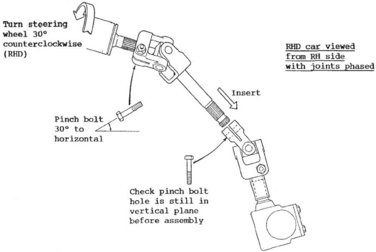
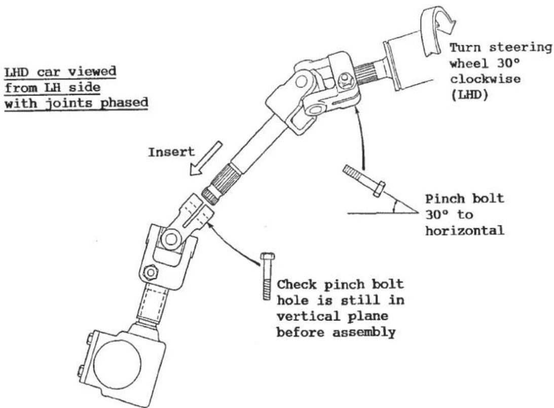
- Tighten the upper column fixings as follows:
Ensure that only a minimal amount of intermediate shaft is allowed to protrude through the upper u/j before tightening the pinch bolt to 22 - 27 Nm (16 - 20 lbf.ft).
Column to scuttle beam: 28 - 30 Nm (20 - 22 lbf.ft)
Column clamp bolt: 11 - 16 Nm (8 - 12 lbf.ft)
- Road test and check the alignment of the steering wheel. Realign if necessary as detailed in sub-section HB.2.
To Remove Intermediate Steering Column Assembly: With S.I.R.
WARNING: Any work on, or removal of the steering column on S.I.R. cars requires that rigorous safety precautions be taken in order to safeguard against unintentional deployment of the inflator module with consequent risk of personal injury or unnecessary S.I.R. system repairs. Follow the procedures below in the order listed to temporarily disable the S.I.R. system and prevent false codes from setting.
a) Turn off ignition.
b) Disconnect the negative battery cable, and tape back to ensure that it cannot contact the battery terminal.
c) From beneath the passenger side fascia, locate and disconnect the six way SIR fascia harness connector block.
d) Unplug the orange 3-way connectoe to the inflator.
- Remove the upper steering column assembly (see sub-section HB.3).
- From beneath the vehicle, remove the pinch bolt securing the lower intermediate shaft to the lower u/j. From inside the vehicle, withdraw the intermediate shaft assembly from the steady bearing and body grommet.
- If necessary, remove the pinch bolt securing the lower intermediate shaft u/j to the upper intermediate shaft, and withdraw the upper shaft.
- If necessary, remove the pinch bolt securing the lower u/j to the steering rack pinion shaft, and withdraw the u/j.
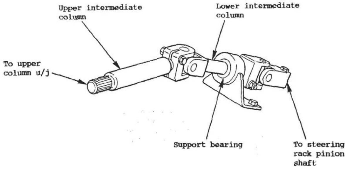
The lower intermediate shaft steady bearing, is an oil impregnated synthetic (Railko) bush pressed into a bracket bolted to the chassis front crossmember. The position of the bracker is set by jig during vehicle manufacture, and should not be disturbed unless the bush is to be replaced.
To replace the bush, remove the two screws securing the bracket, and press out the bush. Press the new bush into position, where it is retained by a rib around the outside of the bush locating in a groove in the housing. The oil impregnated bush is self-lubricating. Fit the bracket to the chassis with the two bolts, but do not tighten at this stage.
To Refit Intermediate Steering Column Assembly: With S.I.R.
- In order to ensure that the lower u/j is not slid too far onto the pinion shaft, with the consequent danger of the shaft end fouling the u/j spider, or of the u/j fouling the chassis, a circlip is fitted onto the pinion shaft followed by a rubber spacer tube.
Align the pinch bolt hole in the lower u/j with the flat on the pinion shaft and fit the u/j onto the shaft to abut the spacer tube, or until the shaft end is flush with the inside of the u/j yoke. Fit the pinch bolt and tighten to 22 - 27 Nm (16 - 20 lbf.ft).
-
Fit the shorter end of the upper intermediate shaft into the lower intermediate shaft u/j with the flat aligned with the pinch bolt hole. Retain with the pinch bolt and a new Nyloc nut and tighten to 24 Nm (18 lbf.ft).
-
Fit the intermediate shaft assembly through the bulkhead seal, through the steady bearing, and into the lower u/j with the flat on the splines aligned with the pinch bolt hole. Fit the pinch bolt and retain with a new M8 Nyloc half nut. Tighten to 24 Nm (18 lbf.ft).
-
Refit the upper steering column assembly (see sub-section HB.3).
-
Temporarily fit the steering wheel and turn as necessary to find the point of minimum clearance between the intermediate shaft assembly and the fully depressed clutch pedal:
- If the lower shaft steady bearing was not disturbed, check that there is a minimum clearance of 5 mm at this point.
- If the lower shaft steady bearing has been renewed or disturbed, adjust the position of the bracket on the chassis to achieve a clearance of 5 - 7 mm before tightening the steady bearing fixing bolts to 11 Nm (8 lbf.ft).
HB.5 - TRACK ROD ENDS & TOE-IN ADJUSTMENT
The track rod ends (outer ball joints) are threaded onto the ends of the track rods, and are secured to the hub carrier steering arms by tapered ball pin shanks and Nyloc nuts. By screwing the track rods in or out of the rod ends, the effective length of the track rods is altered, thereby providing a means of toe-in adjustment for the front wheels.
In order to maintain the required bump steer characteristic, it is important to ensure that the steering rack is centralised in the straight ahead position, i.e. both track rods are the same length, within the limitations of steering wheel alignment (see sub-section HB.2).
Toe-in adjustment: Before measuring the front wheel alignment, set the car to a ride height of 170 mm below the chassis front crossmember.
Specification:
Prior VIN 82 D 3582, 85 D 3887, 82/F 2728
From VIN 82 D 3582, 85 D 3587 82/F 2728, 82/F 5000
Toe-in:
1.6mm each side; +0, -1mm
0.1 to 1.9mm overall
To adjust the toe-in (front wheel alignment), hold the track rod ends by the flats provided whilst releasing their locknuts. Turn each track rod, an EQUAL amount, either to increase the effective length of each track rod (increase toe-in), or to shorten each track rod (reduce toe-in). Take care not to twist the steering rack gaiters during this operation; loosen the gaiter outer clips if necessary. When adjustment is correct, hold the track rod ends and tighten their locknuts to 60 Nm (44 lbf.ft). Recheck toe-in and tighten the gaiter clips.
For full steering geometry specification and adjustment of castor, see sub-section CD.2/3.
Track rod end replacement: If the ball joint boot is damaged, or if any play in the joint is discernible, the joint should be replaced. Before removing the joint, measure the length of visible track rod thread in order that the initial setting of the new joint may be approximately correct. Remove the nut securing the ball pin into the steering arm, and use a ball joint splitter tool to separate the joint from the steering arm. Release the locknut, and unscrew the joint from the track rod.
Thread the new joint onto the track rod and screw up to the position noted before removal. Fit the ball pin into the steering arm from the top, secure with a new Nyloc nut (without washer) and torque tighten to 41 - 47 Nm (30 - 35 lbf.ft). Check and adjust toe-in and tighten the rod end locknuts as above.
HB.6 - STEERING RACK GAITERS
The gaiters fitted at each end of the rack assembly are available as a kit which includes the two gaiters and four clips. The integrity of the gaiters and their sealing to the rack housing and track rods is vital to the longevity of the steering assembly, as any water or dirt ingress will cause rapid wear and deterioration of the moving parts. The gaiters should be carefully inspected at every service, and replaced if showing any signs of damage, wear, age hardening or perishing. A quick check method is to squeeze each gaiter in turn and listen for any escape of air from a gaiter hole, joint, or faulty rack housing.
Only 'Neoprene' type gaiters should be used, recognisable by their flexible rubbery texture and matt appearance. Do not use the more rigid plastic ('Santoprene') gaiters which are less likely to form a satisfactory seal with the rack housing and track rods.
To Fit Gaiter Kit
- Remove the nut securing each track rod end to the hub carrier steering arm and use a ball joint separator to disconnect the joint.
- At each side, mark the position of the track rod end against its track rod, and count the number of visible threads before slackening the track rod end locknut, and unscrewing the rod end and locknut from the track rod.
- Slacken the two clips securing each gaiter, and slide the gaiter off the track rod.
- Inspect the condition of the rack assembly and inner ball joints and replace
the steering unit if necessary. If the assembly is serviceable, clean off any dirt if necessary before lubricating the rack with either EP90 oil (early cars) or, on later cars, Texaco CUP 2 grease or equivalent (lime based, water resistant).
- At each side, fit the new gaiter and clips over the track rod, locate the large end in the groove on the rack housing (pinion end) or just inboard of the end bush locating holes, and secure with the clip. To aid track rod adjustment, apply a small amount of red rubber grease to the track rod groove before locating the outboard end of the gaiter. Do not tighten the clip at this stage.
- At each side, fit the locknut and track rod end onto the track rod, and screw on to the same position as noted prior to removal. Tighten the locknut to 70 - 80 Nm (50 - 60 lbf.ft).
- Fit each track rod end into its hub carrier steering arm, and secure with a new Nyloc nut, tightening to 41 - 47 Nm (30 - 35 lbf.ft). Tighten the gaiter outer clips.
- Check front wheel alignment.
HB.7 - RACK & PINION ASSEMBLY
The manual steering rack and pinion assembly fitted to the Esprit, is maintenance free, and with the exception of the track rod gaiters, is a non-serviceable unit which must be renewed if excessive play develops, exemplified by 'clonking' noises, wheel shimmy, or any more than the smallest amount of free play at the steering wheel. Any attempt to compensate for wear in the straight ahead position by re-shimming the rack thrust pad, may result in tightness or jamming at some other point of rack travel.
The ratio of the rack and pinion gear is 45:1 (45 mm rack travel per pinion revolution), and the ratio of the complete steering system is 15.4:1 (angular movement of steering wheel : angular movement of road wheel).
The rack and pinion assembly is secured to two plinths on the front of the chassis front crossmember via a pair of two bolt clamp brackets and rubber isolator bushes. Lateral location of the unit is assured by a pair of lugs on the non-pinion end of the rack housing, which straddle the chassis plinth.
To Remove Rack & Pinion Assembly
- Remove the front road wheels and disconnect the track rod ends from the hub carrier steering arms.
- Remove the pinch bolt securing the u/j to the steering rack pinion shaft.
- Release the two bolts securing each of the two steering unit clamp brackets, and remove the clamp brackets, rubber mountings, and loose tapping plates.
- Withdraw the pinion shaft from the u/j, and manoeuvre the unit out from the chassis towards the driver's side.
To Refit Rack & Pinion Assembly
- Before fitting the steering unit, check the following points:
- both gaiters are undamaged and correctly located and sealed; squeeze each gaiter to check for air leaks from gaiters, joints or housing.
- the circlip and spacer tube are fitted onto the pinion shaft.
- Feed the unit into position in the chassis from the driver's side and slide the pinion shaft into the u/j with the pinch bolt hole aligned with the flat on the shaft.
- Fit the mounting rubbers around the rack housing, and secure the unit with the two clamp brackets, inserting the tapping plates into the chassis plinths. Tighten the fixings to 16 -19 Nm (12 - 14 lbf.ft).
- Fit the pinch bolt and new Nyloc nut to secure the lower u/j to the pinion shaft, and tighten to 22 - 27 Nm (16 - 20 lbf.ft).
- Fit each track rod end into its hub carrier steering arm, and secure with a new Nyloc nut, tightening to 41 - 47 Nm (30 - 35 lbf.ft).
- Check front wheel alignment.
BRAKES
SECTION JB - ESPRIT S3 & TURBO: PRIOR TO '85 MODEL YEAR
This section is applicable to cars up to and including 1984 Model Year which use solid brake discs and Girling calipers front and rear.
| Section | Page | |
| General Description | - | 2 |
| Front Brake Pad Replacement | JB1 | 2/3 |
| Rear Brake Pad Replacement | JB2 | 3/4 |
| Handbrake | JB3 | 4/5 |
| Front Brake Caliper Overhaul | JB4 | 5 |
| Rear Caliper Overhaul | JB5 | 5/6 |
| Brake Discs | JB6 | 7 |
| Master Cylinder | JB7 | 7 to 9 |
| Servo Unit | JB8 | 10 |
GENERAL DESCRIPTION
The braking system consists of a Girling Type 28 Supervac servo unit attached to a tandem master cylinder with a bore of 19.05mm (0.75 in.) operating type GA2, calipers with 250mm (9.7 in.) diameter discs at the front, and type 9CH sliding caliper with 275mm (10.82 in.) diameter discs at the rear. The rear brakes are mounted inboard.
The separate front/rear hydraulic circuits share a brake fluid reservoir fitted with a low fluid level warning switch. This circuit, which operates a fascia tell tale lamp, may be checked by depressing the test button on the reservoir cap.
The handbrake lever connects via individual cables to each rear brake caliper, and mechanically operates their hydraulic pistons. Each piston incorporates a self adjusting mechanism which operates on footbrake application to compensate for brake pad wear.
JB.1 - FRONT BRAKE PAD REPLACEMENT
Minimum pad thickness = 3mm
Always change brake pads in axle sets.
- After raising the front of the vehicle, remove the front wheels:
WARNING: When both front wheels are raised, do NOT move the road wheels quickly from lock to lock, as this will cause hydraulic pressure to build up within the steering gear, which may cause the rubber bellows to burst or blow off.
- Remove any accumulated road filth from the area of the brake pad.
- Pull out the pad retaining pin clips (A), withdraw the retaining pins (B) and remove the brake pads with the shims (C). Note the position of the dust shield (D) fitted over the brake pads.
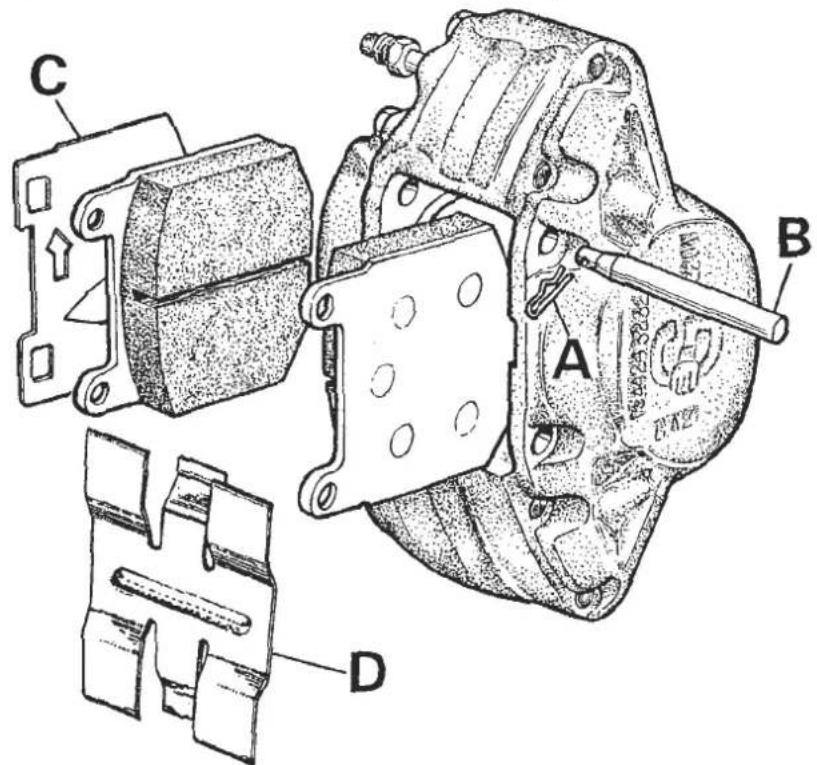
SECTION JB
- To enable the new pads to be fitted, push the pistons in the calipers back into the bores. This action will cause hydraulic fluid to be returned to the master cylinder, which if it has recently been topped-up, may overflow. To avoid this, examine the fluid level and if necessary, remove a quantity of fluid BEFORE pushing the pistons back into the bores. DO NOT USE REMOVED FLUID FOR TOPPING-UP PURPOSES.
- Fit the new brake pads with the shims taking care that both are fitted correctly. The shims are marked with an arrow which MUST point in the direction of forward rotation of the wheel. Replace the dust shield, refit the retaining pins and the locking clips.
- Operate the brake pedal several times to bring the pads into correct operating position. Check that the pads are free to move and that the retaining pins are not fouling the pads.
- Replace the road wheels, lower the vehicle to the ground, check the brake fluid and top up if necessary. Tighten the wheel nuts to the specified torque loading.
CAUTION: The brakes will not work at full efficiency until the new brake pads have bedded-in. If, initially, the brakes are used too heavily, the surface of the pads will burn and irregular braking result. Use the brakes gently for the first few miles and gradually build up brake effort.
JB.2 - REAR BRAKE PAD REPLACEMENT
Minimum pad thickness = 3mm
- Remove the two self locking screws securing the caliper body to the two guide pins, whilst holding the guide pins stationary with a spanner to prevent damage to their dust covers.
- Remove the caliper body and support to avoid straining the flexible hose. Remove the pads and clean the pad abutment areas taking care not to damage the guide pin or piston dust covers.
- Before fitting new pads, the piston must be pushed back into the caliper and the handbrake auto-adjust mechanism reset. Fit a screwdriver against the piston and turn the piston 45° to disengage the adjuster ratchet. Press back the piston (take care that the fluid reservoir does not overflow), and then turn the piston back 45° to re-engage the ratchet.
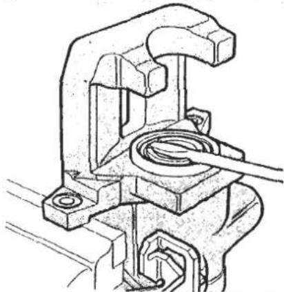
- Fit new pads and damper spring into the caliper bracket, and refit the caliper body, aligning the slot in the piston with the lug on the brake pad backplate.
- Fit new self locking bolts to secure the caliper body to the guide pins. Fit the top bolt first, then compress the pad damper spring and fit the lower bolt. Torque tighten both bolts to 3.2 - 3.6 kgf.m. (23-26 lbf.ft.).
- Operate the footbrake several times to bring the pads to their correct working position and to take up the handbrake adjustment.
CAUTION: The brakes will not work at full efficiency until the new brake pads have bedded-in. If, initially, the brakes are used too heavily, the surface of the pads will burn and irregular braking result. Use the brakes gently for the first few miles and gradually build up brake effort.
JB. 3 - HANDBRAKE
The handbrake lever connects to an actuating link which uses a compensator lever to balance the force applied to each handbrake cable. Late cars may be fitted with a multiplier lever pivoting on the handbrake lever mounting plate, in order to increase the leverage and reduce operator effort.
Access to the handbrake cable adjusters is made via an aperture in the rear end of the sill trim panel, covered by carpet.
The cables should be adjusted to obtain a vertical position of the compensator when the handbrake is applied.
The cylinder end covers on the brake caliper assemblies, contain a handbrake automatic adjustment mechanism to accommodate brake pad wear. Movement of the caliper lever causes a cam to rotate and exert a force via a pushrod and adjuster mechanism, on the caliper piston and brake pads.
The 'relaxed' position of the piston is controlled by the piston seal in the cylinder wall, which pulls the piston back a specified amount after each brake application. As the brake pad wears, and the piston moves outwards accordingly, the ratchet teeth 'B' are pulled past the pawl 'A', so keeping the handbrake mechanism in constant adjustment.
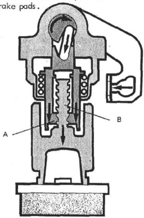
A small amount of lost motion is permitted which prevents over-adjustment, and permits proper relaxation of the pads after each brake application.
In order to press the piston back into its bore (necessary when fitting new brake pads) or to eject the piston from the cylinder (during caliper overhaul), the ratchet mechanism must be disengaged. To do this, rotate the piston 45° in either direction. Turn back to re-engage the ratchet, and align piston slot with the lug on the brake pad backplate.
JB. 4 - FRONT BRAKE CALIPER OVERHAUL
Note: No attempt should be made to remove the bolts and separate the two halves of the caliper body.
- Disconnect the flexible hose from the caliper and remove caliper from the vertical link. Drain brake fluid from the caliper.
- Remove the brake pads as in JB.1 and pull off the piston dust covers.
- Using rag to protect from brake fluid spray, and keeping fingers well clear, use compressed air to eject the pistons from their cylinders.
- Remove the sealing rings from the cylinders taking care not to damage the bores or grooves.
- Clean all parts thoroughly with Girling Cleaning Fluid or unused brake fluid. Examine cylinder bores and piston for any signs of scoring, scuffing or corrosion. Replace the pistons or complete caliper if there is any doubt.
- Lubricate the cylinders and new sealing rings with clean brake fluid and fit the seals into their grooves.
- Fit the pistons and dust covers.
- Refit the calipers (see TDD for torque loading) and brake pads (see JB.1).
- Reconnect the flexible hose and bleed the hydraulic system.
JB. 5 - REAR CALIPER OVERHAUL
- Disconnect the flexible hose and handbrake cable and remove the brakepads (JB. 2).
-
Pull the guide pin dust covers from the caliper bracket, and withdraw the guide pins. Inspect guide pins for any signs of corrosion or seizing, and replace with new parts if in any doubt. Note that the guide pin with the bushing, is fitted to the bottom (trailing) end of the caliper and the plain steel pin to the top (leading) end. Grease the guide pins and check that they slide easily in the caliper bracket. Locate the guide pin dust covers.
-
Turn the piston 45° to disengage the handbrake adjustment ratchet mechanism, before using compressed air to eject the piston from the cylinder. Use rag to protect from brake fluid spray and keep fingers well clear.
4 The handbrake mechanism can be separated from the cylinder body after releasing the three bolts on its cover plate. IMPORTANT No attempt should be made to dismantle the auto-adjust mechanism. If it is faulty, a complete new unit must be fitted.
-
Remove the sealing ring from the cylinder, and clear all parts with fresh brake fluid. Examine cylinder bores and pistons for any signs of scoring, scuffing or corrosion and replace pistons or caliper if in any doubt.
-
Lubricate a new piston seal with clean brake fluid and fit into its groove in the cylinder wall.
-
Lubricate the piston, and fit the dust cover onto the piston as shown. Offer the piston and dust cover assembly to the cylinder with the piston orientated to clear the handbrake auto adjustment (see JB. 2). Locate the lip of the dust cover into the cylinder groove and carefully push the piston fully home through the dust cover. Ensure the dust cover is not trapped between the piston and the bore and that the inner lip of the dust cover is located in the piston groove.

-
Turn the piston 45° to engage the handbrake adjustment ratchet and refit the brake pads and caliper to the car.
-
Reconnect handbrake cable and flexible hose and bleed brake system. OPERATE THE BRAKE PEDAL SEVERAL TIMES TO BRING THE PADS TO THEIR CORRECT OPERATING POSITION.
SECTION JB
JB. 6 - BRAKE DISCS
Check the braking surface on both sides of the brake discs for scoring or corrosion. Replace if in doubt.
Measure the disc thickness and run-out.
| Front | Rear | |||
| Thickness, nominal | 12.7 mm (0.50 in.) | 10.00 mm (0.39 in.) | ||
| Thickness, minimum | 11.4 mm (0.45 in.) | 9.00 mm (0.35 in.) | ||
| Run-out maximum | 0.09 mm (0.0035 in.) | 0.09 mm (0.0035 in.) | ||
If the run-out is excessive, replace the disc.
NOTE: Ensure the front wheel bearings are correctly adjusted before measuring front disc run-out.
JB.7 - MASTER CYLINDER
To Overhaul
- Drain brake fluid from the reservoir, disconnect the brake pipes and remove master cylinder assembly to a clean work area.
- Remove the reservoir retaining pins, and carefully pull the reservoir from the master cylinder. Lever out the two seals.
- Push the plunger down the cylinder and withdraw the secondary plunger stop pin. (9)

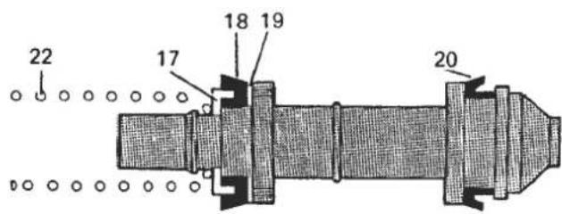
- Remove the retaining circlip and withdraw the primary plunger assembly. Use low pressure compressed air to eject the secondary plunger assembly.
-
Remove the secondary plunger spring, (22) seal retainer (17) recuperating seal (18) and washer (19). Taking care not to damage the plunger, remove the seal (20). Keep the plunger and its spring together at all times.
-
Remove the primary plunger spring (16), seal retainer (17) recuperating seal (18) and washer (19). Slide off the vacuum seals (34) and spacers (24) and (25). Keep the plunger and its spring together at all times.
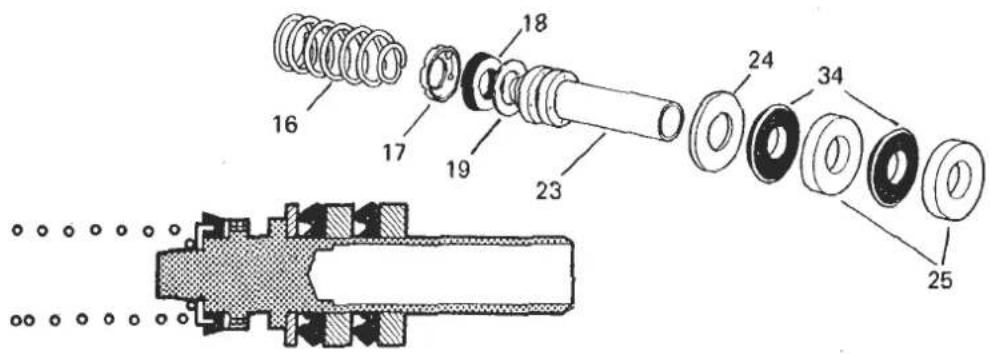
- Check that the breather hole at the rear underside of the cylinder is clear and wash with Girling Cleansing Fluid if necessary.
- The new parts supplied in the overhaul kit indicate which old parts are to be discarded. Clean all remaining parts with Girling Cleaning Fluid, or new brake fluid and examine the cylinder bore meticulously. Unless unmarked, a complete new unit should be fitted. TO HELP PREVENT DAMAGE, IT IS ESSENTIAL THAT GENEROUS AMOUNTS OF UNUSED GIRLING BRAKE FLUID ARE USED AT ALL STAGES OF SEAL ASSEMBLY.
- Fit secondary plunger seal (20) by squeezing between finger and thumb to stretch over plunger lip. Fit washer (19) recuperating seal (18) seal retainer (17) and spring (22). Ensure seals are correctly fitted as shown.

- Fit the primary piston washer, recuperating seal, seal retainer and spring in a similar manner.
- Use the special BMS grease provided to lubricate the inside diameter of the vacuum seals and spacers, and the corresponding outer surface of the primary plunger.
IT IS VITAL THAT THE FOLLOWING INSTRUCTIONS ARE CARRIED OUT PRECISELY OTHERWISE DAMAGE WILL ENSUE TO THE NEW SEALS WHEN INSERTING THE PLUNGERS INTO THE CYLINDER BORE.
- Clamp cylinder in vice, and copiously lubricate cylinder bore and secondary plunger assembly with unused Girling Brake Fluid. Offer the plunger assembly to the cylinder until the recuperation seal is
SECTION JB
resting centrally in the mouth of the bore. Ensuring the seal is not trapped whilst so doing, GENTLY introduce the plunger with a circular rocking motion as illustrated to ease the seal, then SLOWLY push the plunger down the bore in one continuous movement.

-
Repeat this lubricating and fitting procedure exactly for the primary plunger assembly.
-
Press the plunger down the bore to enable the secondary plunger stop pin to be fitted as shown.

- Whilst holding the plunger pressed in, fit the thin vacuum seal spacer into the end of the cylinder, followed by one vacuum seal (lip side first), a thick spacer, the other seal and thick spacer, and retain with the circlip.

-
Lubricate new reservoir seals with brake fluid, and fit into the cylinder. Press the reservoir into position and fit the reservoir retaining pins.
-
Use a new master cylinder/servo 'O' ring, and refit the master cylinder assembly to the servo, torque tightening the two nuts to 2.1 - 2.6 kgf. m (15 - 19 lbf. ft.).
-
Reconnect the brake pipes, refill the reservoir, and bleed the entire system.
JB. 8 - BRAKE SERVO UNIT
The 'Supervac' brake servo is, with the exception of the air filter and non return valve, a non-servicable sealed unit which must be replaced if found to be faulty.
The air filter (surrounds input push rod) should be replaced whenever the brake system is overhauled, and cleaned or replaced more frequently if the vehicle is operated in dusty conditions. The filter is supplied together with the input dust cover and servo/master cylinder 'O' ring in the servo 'service kit' A075J6033F.
The vacuum non-return valve is incorporated into the vacuum hose elbow connector in the front case of the servo unit. The valve is a push fit into a grommet, and is supplied complete with new grommet. Use the grease supplied to lubricate the ribs of the NRV before assembly.
As a quick check of servo operation proceed as follows:
With engine stopped, press the brake pedal several times to exhaust the servo unit of vacuum. Keeping the pedal pressed (which should be 'hard' and 'high') start the engine; the pedal should drop slightly as the servo vacuum builds up.
BRAKES
SECTION JC - ESPRIT S3 & TURBO: 1985 MODEL YEAR ONWARDS
This section is applicable to 1985 Model Year Esprit variants which use ventilated front disc brake assemblies similar to those used on Excel models and Bendix Series 3 ACG rear disc brake assemblies.
| Section | Page | |
| General Description | - | 2 |
| Front Brake Pad Replacement | JC1 | 2/3 |
| Rear Brake Pad Replacement | JC2 | 3 to 5 |
| Handbrake Adjustment | JC3 | 5/6 |
| Front Caliper Overhaul | JC4 | 6/7 |
| Rear Caliper Overhaul | JC5 | 7/8 |
| Brake Discs | JC6 | 8 |
| Servo Unit | JC7 | 8 |
| Master Cylinder | JC8 | 9/10 |
GENERAL DESCRIPTION
The braking system comprises a Bendix 'Master Vac' servo unit and tandem master cylinder operating single piston sliding calipers on each wheel with ventilated front and solid rear discs. The separate front/rear hydraulic circuits share a brake fluid reservoir which incorporates a 'Nivocode' low fluid level warning switch. This circuit, which operates a fascia tell-tale lamp, may be checked by depressing the test button on the reservoir cap.
The handbrake lever connects via individual cables to each rear brake caliper, and mechanically operates their hydraulic pistons via a self adjusting mechanism.
JC.1 - FRONT BRAKE PAD REPLACEMENT
Pad thickness may be checked using the inspection hole in the caliper.
Standard pad thickness - 10.5mm (0.41 in.) Minimum pad thickness - 2 mm (0.08 in.)
To remove pads
-
Remove the bolt from the lower of the two caliper sliding pins, and swing up the caliper to allow access to the pads. The caliper may be supported in the raised position by inserting a bolt into the torque plate hole.
-
Slide out both brake pads. Referring to the illustration remove each anti-rattle spring/guide plate/support plate ONE AT A TIME, and replace with the new item supplied with the new pad set.
NOTE: Pay special attention to the correct assembly of anti-rattle springs and pad guide plates to the caliper. Most of these are handed.
Note that the inner pad guide plate forms a solid abutment and is fitted to the top (or thrust) end of the caliper, whilst the inner pad anti-rattle spring is fitted to the lower end.
- Fit the anti-squeal shim to the outer pad and insert into the caliper, ensuring that the anti-rattle spring tongues are tucked into the brake pad backplate slots.
Insert the inner pad into the caliper.
- Lower the caliper cylinder, and secure with the lower sliding pin bolt, torque tightening to 1.6 - 2.4 kgf. m. (12 - 17 lbf. ft).
NOTE: If new pads are fitted it will be necessary to push the piston back into the caliper bore. This action will return fluid to the master cylinder, which may, if it has been topped up, overflow. Remove fluid from the master cylinder reservoir beforehand if necessary.
- Press the brake pedal several times to bring the pads to their correct running position.
SECTION JC

CAUTION The brakes will not work at full efficiency until the new brake pads have bedded-in. If initially, the brakes are used too heavily, the surface of the pads will burn and irregular braking result. Use the brakes gently for the first few miles and gradually build up brake effort.
JC. 2 - REAR BRAKE PAD REPLACEMENT

- Pull out the locking clips from both caliper retaining plates.
- Using a pin drift, drive out one retaining plate, and then remove the other.
- Lift away the caliper, and support clear without stressing flexible hose.
- Remove the brake pads and anti-rattle springs.
- Before fitting new pads, it is necessary to retract the caliper piston in its bore. To do this, use a 1/4 " drive ratchet in the slot of the piston to screw the piston clockwise down its handbrake adjuster mechanism. Take care that the fluid reservoir does not overflow during this operation. When fully retracted, screw out again until the slot is parallel with the two support wings, and the groove is toward the bleed nipple side of the cylinder as shown.

- Fit the brake pads, with their anti-rattle springs into the caliper bracket
- Refit the caliper over the pads ensuring that the caliper wire springs are located correctly, and slide in both retaining plates. Fit the locking clips.
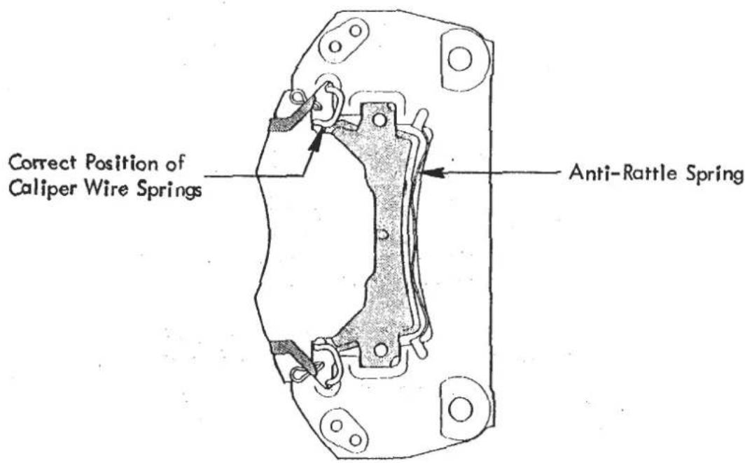
- Operate the footbrake several times to bring the pads to their correct working position and to take up the handbrake adjustment.
JC 3. - HANDBRAKE ADJUSTMENT
It is a feature of the Bendix handbrake mechanism that a large amount of handbrake lever travel is required in order for the handbrake to work efficiently and for the automatic adjustment to function. For this reason, a 'fold down' type handbrake lever is used to ease driver entry/exit.
The handbrake is applied by pulling the lever upwards in the usual manner. After application, the lever may be pushed down again (WITHOUT pressing release button in end of handgrip) whilst the fascia tell tale lamp warns of handbrake application. To release the handbrake, pull lever up, press release button and HOLDING BUTTON PRESSED IN, lower lever fully.
The handbrake lever is connected via a short link to a multiplier lever to increase leverage and reduce operator effort. The multiplier lever connects to an actuating link which uses a compensator lever to balance the force applied to each handbrake cable.
The Bendix calipers incorporate a screw thread self adjusting mechanism within their hydraulic cylinders, which keeps the mechanical handbrake linkage adjusted with each application of the footbrake. For this system to function correctly, it is essential that each caliper handbrake lever is allowed to return fully, and is not prevented from doing so by maladjustment of the handbrake cable.
To check that this condition is achieved, with the handbrake 'off', measure the distance between the cable abutment and caliper lever as shown.

Page 6
SECTION JC
After verifying this dimension, any slack in the cables may be adjusted out at their forward abutment inside the driver's sill trim panel. For access, slide the driver's seat fully forward and lift the rear end of the sill carpet to expose the trim panel aperture. After adjustment, re-check the caliper lever 'off' dimension as above.
JC.4 - FRONT CALIPER OVERHAUL
- Disconnect the brake hose from the caliper brake pipe and bracket. Remove the caliper swing release bolt, raise the caliper and draw off from the top slide pin.
- Remove the sliding bush and its rubber boots.
- Remove the top pin boot from the caliper using a small chisel as shown.


- Remove the spring ring and boot from the piston bore and use compressed air to eject the piston from the cylinder.
WARNING: Keep fingers well clear during this operation, and use rags to guard against brake fluid spray.
- Remove piston seal from cylinder.
- Reassembly. Apply rubber grease to parts as indicated.
- Instal piston seal into cylinder bore, and insert piston. Fit cylinder dust boot, and retain with spring ring.
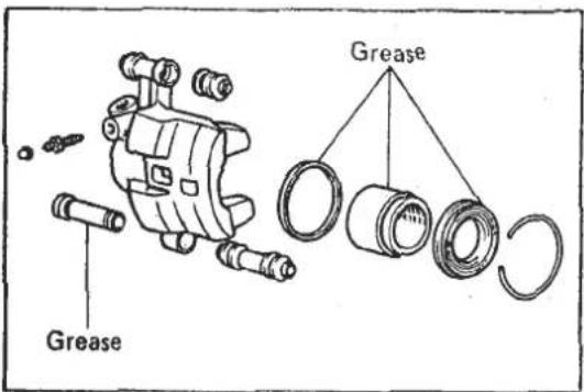

- Fit the top slide pin boot by using a 21mm socket as shown.
- Fit the sliding bush with its two boots.
SECTION JC
-
Install the caliper onto the top slide pin, swing down, and refit the caliper swing release bolt. Torque tighten to 1.6 - 2.4 kgf.m. (12 - 17 lbf.ft.).
-
Reconnect the brake hose, and bleed the brakes.
JC. 5 - REAR CALIPER OVERHAUL
- Disconnect the handbrake cable and brake hose from the caliper.
- Remove the locking clips, slide out the caliper retaining plates, and remove caliper to bench.
- Clean the caliper thoroughly. Remove piston boot. Using a 1/4 " drive ratchet, unscrew the piston from the handbrake adjustment mechanism.
- Using a rag to protect against brake fluid spray, and keeping fingers well clear, use compressed air to eject the piston from the cylinder. Remove seal from groove in cylinder.
- Clean the groove, cylinder bore and piston with methylated spirit and dry with compressed air. Inspect the groove, bore and piston surface for any signs of scratching or pitting. If any such signs are apparent, a replacement cylinder assembly should be fitted.
- Fit a new seal into the cylinder groove. Lubricate the piston and bore with brake fluid and press the piston into the cylinder.
- Smear the exposed part of the piston with the special Lockheed grease supplied in the seal kit, and fit a new dust boot.
- Screw the piston fully in along the handbrake adjuster mechanism, and then position with the piston slot parallel with the two support wings and the groove toward the bleed nipple side. (See brake pad replacement procedure JC. 1).
Cylinder Removal If it is necessary to replace a cylinder assembly, special spreader tool T000T0556 must be used to avoid damaging the special protective coating on the cylinder and wings of the carrier bracket:
a) Position the tool as shown and turn the screws (A) to adjust the alignment of its two arms against the two wings of the carrier bracket.
b) Gradually tighten the two nuts (B) until the cylinder is no longer gripped by the carrier bracket. It may be necessary to re-position the tool to enable the cylinder to move easily.
c) Using a 3mm allen key or similar, depress the spring loaded pawl and slide the cylinder out of the carrier.

Page 8
SECTION JC
Replacement
d) With the tool holding the wings of the carrier apart, slide the new cylinder into the carrier bracket whilst depressing the locking pawl. Note Check that the cylinder is fitted the correct way up.
e) Ensure that the pawl locks into the carrier bracket locating hole and remove the spreader tool.
JC.6-BRAKE DISCS
Check the braking surface on both sides of the brake discs for scoring or corrosion. Replace if in doubt.
Measure the disc thickness and run-out:
| Front | Rear | |
| Thickness, nominal | 20.0 mm (0.79 in.) | 12.0 mm (0.47 in.) |
| Thickness, minimum | 19.0 mm (0.75 in.) | 11.0 mm (0.43 in.) |
| Run-out, maximum | 0.15 mm (0.006 in.) | 0.20 mm (0.008 in.) |
If the run-out is excessive, replace the disc.
NOTE Ensure the front wheel bearings are correctly adjusted before measuring front disc run-out.
JC. 7 - BRAKE SERVO UNIT
The 'Master-Vac' brake servo is, with the exception of the air filter and non return valve, a non-serviceable sealed unit which must be replaced if found to be faulty.
The air filter (surrounds input push rod) should be replaced whenever the brake system is overhauled, and cleaned or replaced more frequently if the vehicle is operated in dusty conditions.
The vacuum non-return valve is incorporated into the vacuum hose elbow connector in the front case of the servo unit. The valve is a push fit into a grommet, and is supplied complete with new grommet.
As a quick check of servo operation proceed as follows:
With engine stopped, press the brake pedal several times to exhaust the servo unit of vacuum. Keeping the pedal pressed (which should be 'hard' and 'high') start the engine; the pedal should drop slightly as the servo vacuum builds up.
When replacing a servo unit, ensure that the input pushrod is located in the brake pedal lower hole marked 'B' (Brake) and not in the upper hole 'C' (Clutch)
JC. 8 - MASTER CYLINDER OVERHAUL
-
Disconnect the fluid level switch leads, release the three brake pipes from the cylinder and remove the two nuts and washers securing the master cylinder to the servo. Remove the master cylinder assembly from the vehicle to a clean workplace before further dismantling.
-
Drain the reservoir and pull out from its two master cylinder grommets.
-
Push on the primary piston and remove the stop screw from the underside of the cylinder, and circlip from the cylinder end.
-
Withdraw the primary piston assembly and eject the secondary piston assembly and spring using compressed air (max 3 bar). Never tap or strike the master cylinder to remove the piston.

- Clean all parts with methylated spirit or brake system cleaning fluid and inspect. If the master cylinder bore shows any signs whatever of scoring, wear, or corrosion, the complete unit should be replaced.
Note: The screw securing the return spring to the primary piston is factory set and must not be disturbed.
-
Coat both new piston assemblies from a master cylinder repair kit with clean brake fluid and insert the secondary piston assembly with its spring into the cylinder. Use a screwdriver with rounded blade to ease sealing washer entry into the bore, and a rounded end 3mm diameter brass rod to ease the seals past the reservoir ports and stop screw hole.
-
Fit the primary piston assembly and spring in a similar manner, and retain in the cylinder by inserting the brass rod through the rearmost reservoir port, whilst pushing on the piston.

-
Coat the exterior of the projecting primary piston tube, vacuum sealing washers, and guide bush with the silicone grease provided in the repair kit.
-
Fit a stop washer and one vacuum sealing washer (lip side first) over the piston tube and insert into the cylinder using a rounded blade. Fit the guide bush, second vacuum sealing washer (lip side first) and second stop washer in a similar manner, and retain with the new circlip.

- Using a new sealing washer, fit the secondary piston stop screw into the cylinder body. Tighten to 1 kgf.m. (7.5 lbf. ft.). Press on the primary piston, and remove the brass rod from the reservoir port.
- Refit the reservoir assembly to the master cylinder using new grommets.
- Refit the master cylinder to the servo, using a new 'O' ring and tightening the two nuts to 1.4 kgf. m (10 lbf. ft.).
- Refit the brake pipes into the master cylinder ports, refill the reservoir with the specified brake fluid, and bleed the complete system. Connect the low fluid level switch leads.
COOLING SYSTEM
SECTION KB - ESPRIT S3 & TURBO
| Operation | Page | |
| General Description | KB.1 | 1 to 7 |
| Drain/Refill Procedure | KB.2 | 7/8 |
| Cooling Fans - Replacement of Early Type Motors | KB.3 | 8/9 |
| Cooling Fans Thermal Trip | KB.4 | 9/10 |
| Cooling Fans Thermal Switch | KB.5 | 10/11 |
| Replacement of Early Type Rad.Duct Stays. | KB.6 | 11 |
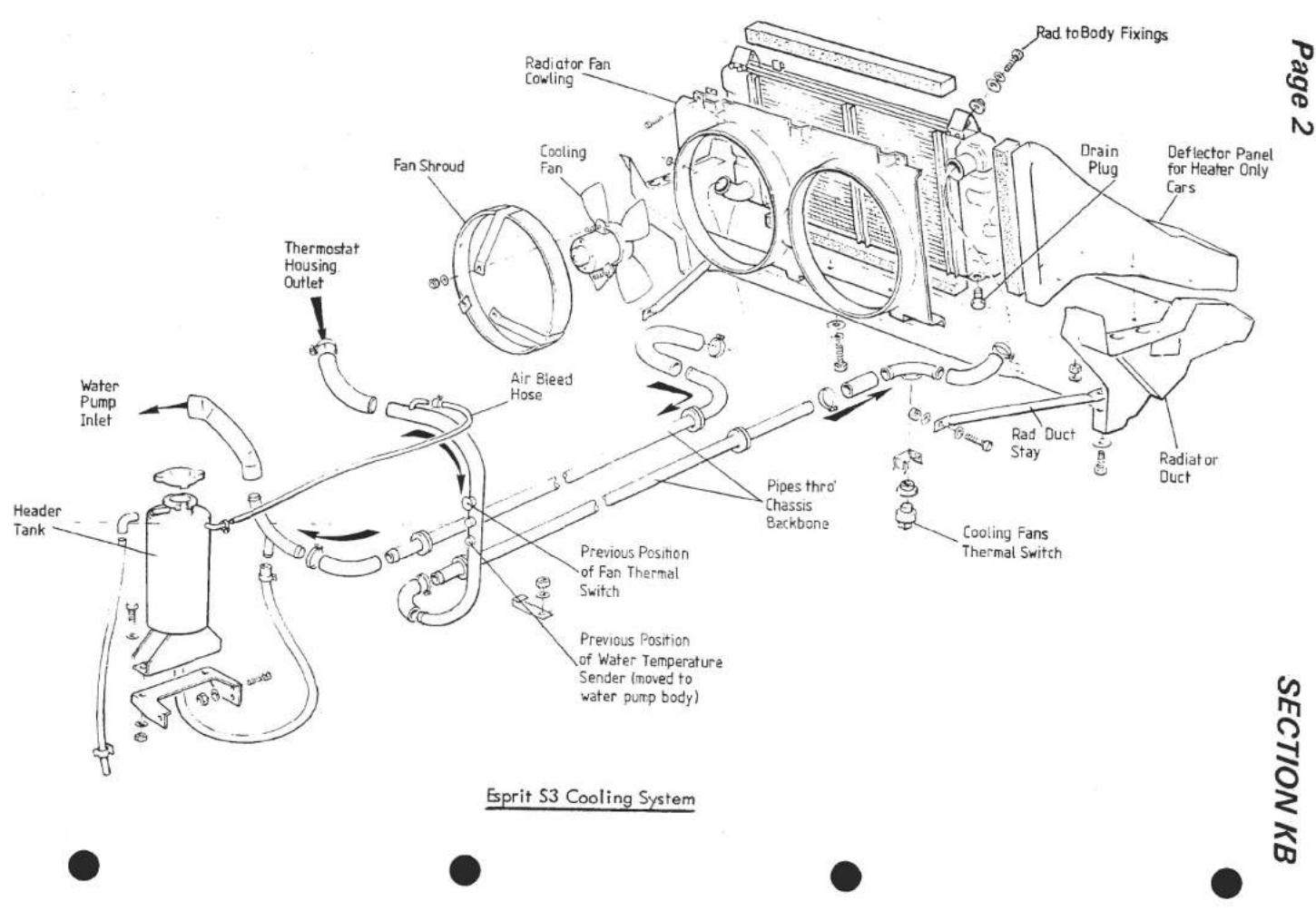


SECTION KB
Page 3

Page 4
SECTION KB


SECTION KB
Page 5
Coolant Circulation Diagram - Esprit S3 & U.S.A. Turbo

Page 6
SECTION KB
KB.1 - GENERAL DESCRIPTION
A centrifugal water pump is mounted on the front face of the cylinder block and is driven by a single 'V' belt from the crankshaft. Coolant is pumped by the impeller into the front of the block, around the 'wet' cylinder liners and into the cylinder head.
Esprit S3 and U.S.A. Turbo: Water leaves the cylinder head via a pipe cast integrally with the inlet manifold, with, on U.S.A. Turbo models, an additional offtake from the front face of the head, and flows into the thermostat housing which is above and integral with the water pump housing. When the thermostat is closed, water flows downwards back into the water pump to commence another cycle. When the thermostat opens, this route is closed off and water is directed upwards past the thermostat and into pipework leading to the front mounted radiator. Coolant returning from the radiator flows back into the water pump impeller housing to commence another cycle.
DOM/ROW Turbo: On these cars, water leaves the cylinder head from a pipe in its front face and via outlets between the inlet ports linked by an external collector pipe. These two streams converge and flow to a remotely mounted thermostat at the right hand front of the engine bay. When the thermostat is closed, water is directed via a 'by-pass' pipework route back to the water pump, but when the thermostat opens, coolant flows forward to the front mounted radiator before returning to the water pump.
A header tank is fitted at the right hand rear of the engine bay and is connected with the water pump inlet pipework (S3 & USA) or the by-pass pipework (DOM/ROW Turbo).
The radiator is located in the nose of the car and is mounted into a G.R.P. rad. duct fixed to the underside of the spoiler and front luggage compartment. Turbo models use a full width radiator provided with 3 cooling fans whilst Series 3 vehicles use a smaller 2/3 width radiator with 2 cooling fans. Series 3 cars with air conditioning have a similarly sized condensor mounted ahead of the radiator and offset to the opposite side of the rad. duct with the non overlapping portion provided with its own condensor cooling fan.
KB.2 - DRAIN/REFILL PROCEDURE
It is most important that the coolant contains a corrosion inhibitor to protect the aluminium alloy of the Lotus engine. A minimum of 25% inhibitor/anti freeze should be used all year round with up to 60% in the coldest climates. All cars are filled with a 40% mix at the factory.
To drain the system, set the heater temperature control to hot, release the header tank cap and remove the radiator drain plug. Also release hose connections in the engine bay as necessary to fully drain pipework To refill the system, refit hose connections securely, replace drain plug and, on Turbo models, open the radiator bleed plug from inside the front luggage compartment.
Fill with coolant until a steady stream flows from the bleed. Close the bleed and add coolant until the system is fully filled. Run the engine to operating temperature and open the bleed until a continuous stream of water flows out. Close the bleed, allow the engine to cool, and fill to within 50mm (2 in.) of the bottom of the header tank neck.
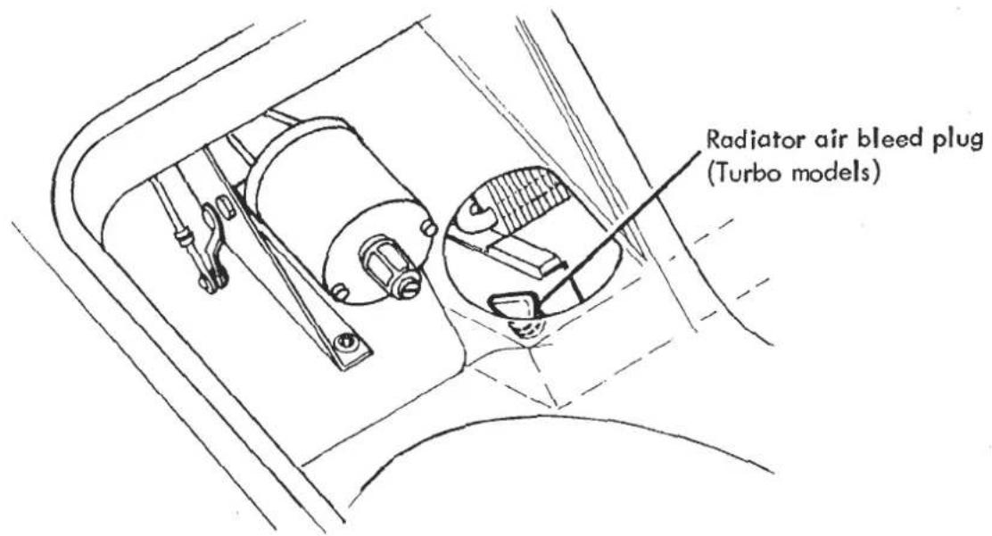
KB.3 - COOLING FANS - REPLACEMENT OF EARLY TYPE MOTORS.
Early Series 3 and Turbo models (prior to mid '83) used cooling fan motors A074M6027Z with rivetted metal fan blades, whilst later cars use a fan motor assembly with an orange plastic blade. If it is necessary to replace an earlier type fan motor, it is recommended to fit the later type fan motor assembly in the following manner.
Parts Required
Qty. per Motor
| Fan Motor | A082K6026H | A/R |
| Fan, rad. cooling (plastic) | A082K6027H | 1 |
| Circlip, fan to motor | A082K6029F | 1 |
| Washer, fan to motor | A082K6028F | 1 |
| Spacer, motor to mtg. | A079K4175 | 3 |
| Washer, shakeproof | A075W4046Z | 3 |
| Nut, plain, M6 | A075W3020Z | 3 |
| Permabond, A136 | A074B6009V | A/R |
| Extension lead (S3) | A085M4194F | 1 |
| Reverse Polarity Lead (Turbo) | A082M4193F | 1 |
- Remove the old fan and motor from its mounting shroud.
-
Enlarge the fan motor fixing holes in the shroud legs to 6mm clearance.
-
Fit the new fan and motor assembly, using spacers A079K4175 between the motor and shroud legs as shown, and Permabond A136 on the fan motor mounting studs.
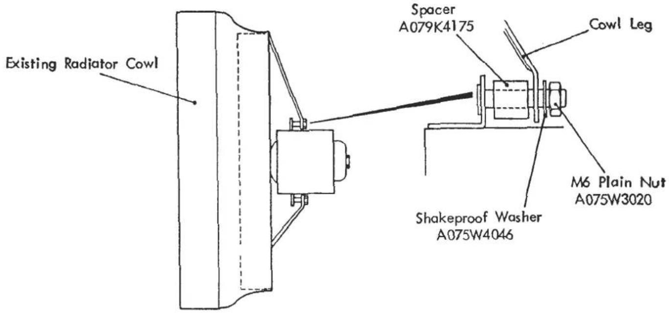
- On Series 3 models, discard the existing reverse polarity connection

and connect to loom using extension lead A082M4194.
On Turbo models connect motor to loom using reverse polarity lead A082M4193.
- Switch on fans (bridge 'Otter' switch) and check correct direction of rotation of each individual fan, ie: draws air through radiator and blows backwards, rotating anti-clockwise when viewed from behind.
The fan fail tell-tale will function as previously.
KB.4 - COOLING FANS THERMAL TRIP
Early Turbo models, S3 cars with air conditioning, and Series 3 cars with heater prior to commonisation with Turbo fascia (mid '85) used a fused relay in the cooling fan circuit located at the left hand front of the front luggage compartment. Later cars were fitted with a revised circuit to incorporate a double pole relay and a modular three pole thermal circuit breaker with manual reset. On these cars, an excess current in any one or more motors will cause its own thermal circuit breaker to operate. If any
thermal trip is open, or any motor fails to rotate at an effective speed, an earth path or voltage difference is created and the fan failure tell tale will light. Pressing down the red reset button on the trip housing (adjacent to windscreen washer reservoir) will restore any tripped circuit.

The cooling fans thermal switch (sometimes referred to by its manufacturers name, 'Otter') is fitted into a water pipe between the thermostat outlet and radiator inlet, using a special grommet and spring clip. Never re-use a grommet, but renew each time the switch is removed.
Cars used in hot climates are fitted with a blue colour coded switch which makes/breaks at temperatures of 82/72°C. The switching point for cars in temperate climates was raised from 86/76 to the 92/82 of the current green colour coded switch.
On DOM/ROW Turbo models the switch is fitted in the radiator inlet elbow pipe. Until Dec. '84, the pipe was fitted with the switch pointing upwards but the possibility of an air pocket being trapped around the switch and the consequent erroneous temperature sensing, led to the pipe and switch being inverted.

SECTION KB
On an earlier car, if inconsistent fan operation is experienced, or if the thermal switch or water-pipe is disturbed for any reason, the elbow pipe should be re-fitted in the 'inverted' position as shown.
Esprit S3 cars prior to mid '85 and U.S.A. Turbo models have the switch fitted horizontally into the water pump outlet pipe. Later S3 cars adopted the radiator inlet pipe location of the Dom. Turbo.
KB.6 - REPLACEMENT OF EARLY TYPE RAD. DUCT STAYS
Early Series 3 and DOM/ROW Turbo cars used radiator duct stays fabricated from 'U' section channel and using an 'L' bracket to fix the stay to the chassis. Later cars used a more durable tubular stay which may be fitted to earlier cars in the following manner.
Parts Required
| Rad. Duct Support Tube, RH | A082K4188K | 1 |
| Rad. Duct Support Tube, LH | A082K4189K | 1 |
| Setscrew, M6 x 20, Tube/Chassis | A075W1030Z | 2 |
| Washer, flat, Tube/Chassis | A075W4013Z | 2 |
| Nut, Nyloc, M6, Tube/Chassis | A075W3009Z | 2 |
Remove and discard existing stays and 'L' brackets.
Drill a 7mm diameter hole each side of the chassis front frame as shown, and paint with a zinc rich primer.

Fit the rear end of each tube to the chassis at this point using the fixings listed, and secure the front end to the rad. duct with the existing fixings, re-drilling if necessary.
FUEL SYSTEM
SECTION LA - EXCEL & ESPRIT S3
| Operation | Page | |
| General Description | LA.1 | 2 |
| Installation of Revised Fuel | ||
| Filteration System | LA.1A | 2 |
| Carburettor Theory of Operation | LA.2 | 3 to 7 |
| Float Level Checking | LA.3 | 8 |
| Carburettor Balancing Procedure | LA.4 | 8/9 |
| Carburettor Mounting | LA.5 | 9 |
LA.1.-GENERAL DESCRIPTION
Esprit Series 3
Two fuel tanks are fitted, one ahead of each rear wheel arch. A separate filler neck with lockable cap is provided for each tank, and the two tanks are interconnected by a balance pipe. A single sender unit for the fuel gauge is fitted into the top of the right hand tank.
Fuel is fed from the left hand tank to an electric fuel pump fitted beneath the left hand front corner of the engine bay. From here fuel is pumped through a line filter at the left hand front of the engine bay, to a 'Flowlock' valve at the right hand side of the engine bay. The 'Flowlock' valve is a solenoid operated fuel line valve designed to shut off the fuel supply to the engine except when the solenoid is energised by switching on the ignition. A plastic fuel pipe then carries fuel to the carburettors.
EXCEL
A single fuel tank is fitted between the rear wheel arches at the front of the boot and is provided with a filler neck and lockable cap on the left hand side. The fuel gauge sender unit is fitted into the top of the tank. On cars prior to mid '85, fuel is drawn through a gauze filter incorporated into the banjo bolt fuel take off, and through a 'Flowlock' valve before reaching the electric pump. Both pump and 'Flowlock' valve are contained within the spare wheel well at the front of the boot. Fuel is then pumped through a plastic pipe running through the chassis backbone and into the carburettors.
Early cars were fitted with a filter in the fuel pipe to carburettor adaptor. This was later replaced by a float needle valve filter within the carburettor.
From mid '85 onwards, a revised fuel filtration system was fitted incorporating a replaceable paper element fuel filter. With this system a coarser mesh filter (450 microns) is used on the tank banjo bolt, from which fuel flows to the fuel pump. Fuel is then pumped through a filtration unit mounted to the right of the fuel tank, then through the flowlock valve and to the carburettors.
On earlier Excel models, where a history of persistent fuel starvation problems have been experienced, the revised fuel filtration system can be installed.
LA.1A. - INSTALLATION OF REVISED FUEL FILTERATION SYSTEM
| PARTS REQUIRED: | Banjo Bolt/Filter Assy. | C084L0181F | 1 off |
| Crush Washer (Banjo/Filter Assy.) | A075L6022F | 2 off | |
| Fuel Pipe - Tank to Pump | A089L0211F | 1 off | |
| Fuel Pipe - Pump to Filter | A089L0212F | 1 off | |
| Fuel Filter Assy. | A089L6012F | 1 off | |
| Fuel Pipe - Filter to Flowlock | A089L0213F | 1 off | |
| Set Screw M6 x 20 | A075W1030F | 2 off | |
| Washer 6 x 20 x 2.5 | A075W4016F | 2 off | |
| Nyloc Nut M6 | A075W3009F | 2 off |
5)
Remove existing fuel pipe from tank to flow lock and flowlock to pump and discard.
Disconnect fuel pipe from pump outlet.
Fit new banjo bolt/filter assy. (C084L0181F) using new crush washers and new fuel pipe (A089L0211F) from tank to pump inlet Torque tighten banjo bolt/filter assy. to 2.8 kgf.m (20 lbf. ft.).

Fuel System Schematic Layout
6)
Fit new fuel pipe (A089L0212F) from pump outlet to filter inlet (rearmost connection).
Reverse the flowlock on its existing mounting (direction of flow arrow towards engine) and fit new fuel pipe (A089L0213F) from filter to flowlock. Clip/tie wrap pipe as shown. Connect the existing (front to rear) fuel pipe to the flowlock. Route pipe in a loop inside boot - do not push pipe forward through grommet in body.
7)
When refilling the tank, strain the drained petrol through a fine mesh filter (e.g. ladies stocking or tights) to avoid any contaminated fuel entering the tank. ENSURE THAT ALL FUEL PIPE CONNECTIONS ARE SECURE AND THAT THERE ARE NO FUEL LEAKS
8.
Refit tank board, spare wheel, boot floor, RH rear wheel and reconnect battery.
LA.2. - CARBURETTOR THEORY OF OPERATION
Carburettor Type - Standard Engines - Dellorto DHLA 45E - 'H.C.' Engines - Dellorto DHLA 45D
Fuel Supply
Fuel from the union (1) passes through the filter (2) and reaches the needle valve seat (18), where the needle valve (17) attached to the float (15), controls the

fuel flow into the float chamber, thereby maintaining a constant level.
The float chamber is vented to atmosphere (via the airbox) through the hole (4) in the chamber (3).
Starting
With the choke valve (8) opened fuel metered through jet (14) passes into the emulsion tube (13), where it mixes with air from the channel (16), communicating with the float chamber top through hole (6). The mixture formed flows, through holes (7), into the valve chamber (9), further mixing with air from the two channels (5).
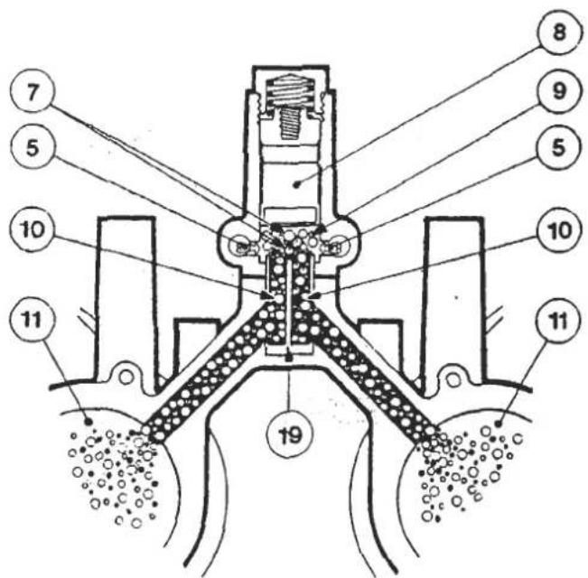
With the choke valve (8) partially closed, when a leaner mixture is required, mixture flows into the valve chamber (9) through one of the two outlet ports (7), further mixing with air from the two channels (5), which, in this condition, are partially closed.
With the choke valve (8) closed, communication between the main barrels and the starting circuit is cut off as is also communication between the two barrels by means of the dividing bushing (19).
Idling
Fuel coming from the float chamber, metered by the idle jets (21), mixes with the air from the well (23) through channels (22); the mixture thus formed, through channels (24) arrives to the adjustment screw (27) and then, metered, flows into the main barrels (11) downstream the throttle valve (12).
Replacing the plug (26) with an adaptor connected to a suitable manometer it is possible to check, through channel (28) the pressure existing in the barrels (11) with the throttle valve (12) in idling position and equalize the air flow adjusting the bypass screw (25) which controls the hole (29).
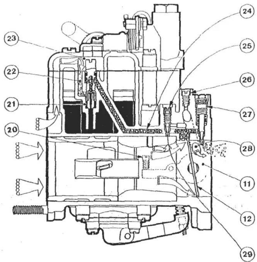
Progression
On first opening the throttle valves (12), that is when passing from idle to full throttle, mixture arrives to barrels (11) also through progression holes (32).

Acceleration
On opening of throttle valves (12), lever (39) attached to spindle (38), by means of the rod (40) and the spring (41) pushes the pump lever (43) which acts directly on the diaphragm (44) held out by the spring (45).
Moving pf the diaphragm (44) causes delivery of fuel to the main barrels (11) through the respective valves (36) and jets (37).
On closing of throttle valves (12), diaphragm (44) returns to the original position pushed by the spring (45) and draws fresh fuel from the fuel well (33) through the valve (35).
The pump injection quantity can be adjusted by nut (42).
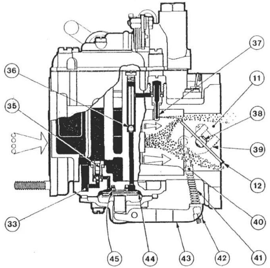
Full Throttle
With the throttle valves (12) opened, fuel from the float chamber (46) metered by the jets (47), enters the well (48) and mixes with air metered by the air corrector (49).
The mixture thus formed, passes through the inner venturi (50) where it further mixes with air drawn through the main barrel of the carburettor, flows into the venturis (51) and then, through the main barrels (11) reaches the engine.
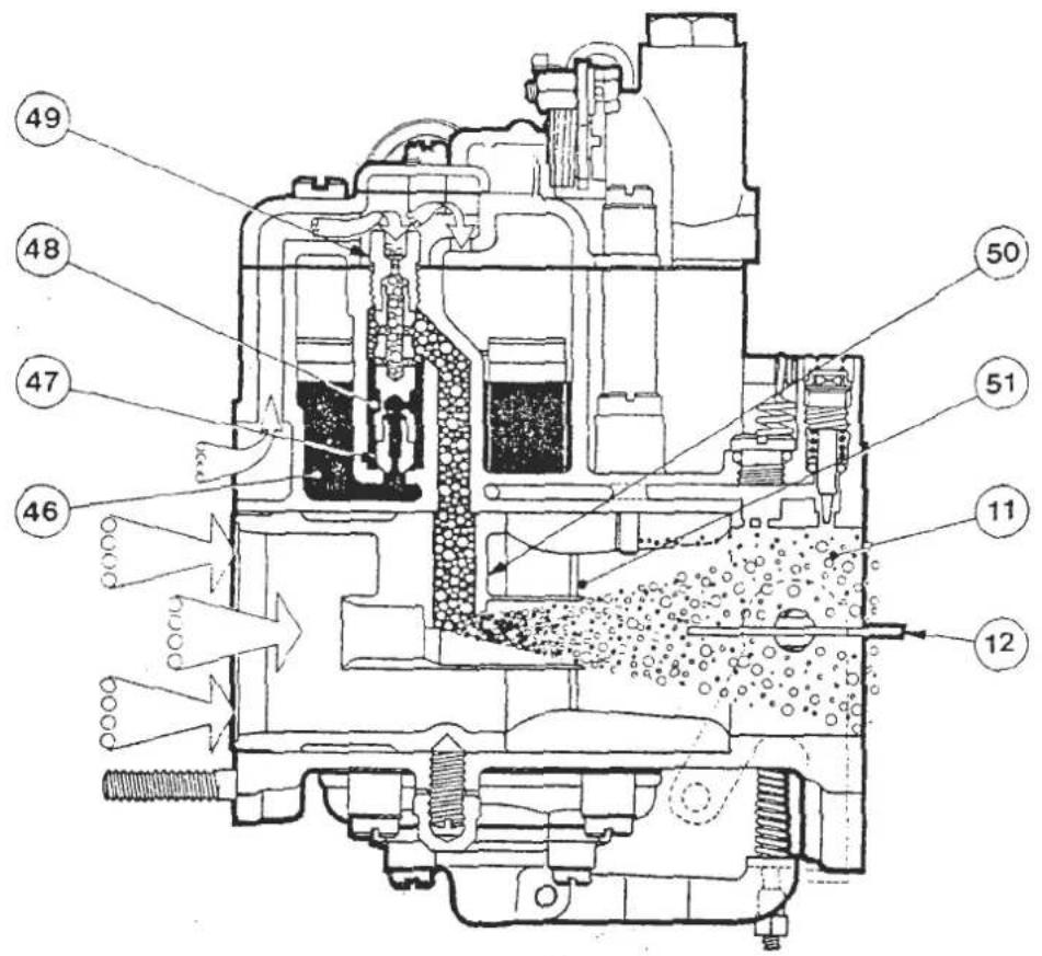
Power Jet Operation (H.C. engines only)
At high engine speeds, an additional amount of mixture flows through the needle jet (52), upstream the inner venturi (50); mixture is composed of fuel drawn from the float chamber through channel (56) and metered by the jet (55), mixed with air metered by the calibrated passage (54) and drawn from the float chamber top (53).

LA.3. - FLOAT LEVEL CHECKING
Remove the carburettor top complete with float assembly. Ensure the correct weight of 8.5g is indicated on the float, and that the float assembly pivots freely on its pin. Hold the cover vertical with the float hanging downwards and in light contact with the needle.
Measure the dimension 'A' between float and gasket as shown in the diagram, for each float of the assembly, and if necessary carefully bend the float arm at 'B' to correct.
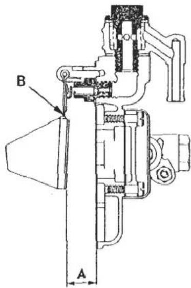
LA.4. - CARBURETTOR BALANCING PROCEDURE
- Ensure ignition timing is correct and the air filter and all trunking etc. fitted.
- Remove anti-tamper caps from idle CO adjustment screws and balancing screws.
- Replace vacuum tapping screws with manometer adaptors T000T0496 and connect to manometer T000T0499.
- Fully close all balancing screws (do not 'graunch').
- Set idle CO adjustment screws 6 x 1/2 turns open, and start engine.
-
With engine at normal running temperature with ACU off and cooling fans on, adjust throttle stop screw to give specified idle speed of 850 to 950 rpm.
-
Adjust throttle coupling screw to balance lower of mercury columns 1 and 2 with lower of mercury columns 3 and 4 to within 3 mm.
- Considering the front carburettors, gradually unscrew the air bleed balancing screw of ONLY the carb. barrel with the highest mercury column, until it is balanced with the lower column to within 3 mm.
- Carry out the same procedure for the rear carburettor, and if necessary re-adjust the throttle coupling screw to balance all columns to within 3 mm. Ensure correct idle speed is maintained.
- Correct exhaust gas analyser to the exhaust tailpipe and check CO reading. Move all idle CO adjustment screws the same amount in or out 1/4 of a turn at a time to bring CO level within the range 0.7 - 1.5%.
- Disconnect manometer and adaptors, and replace blanking screws. Fit new anti tamper caps where necessary. Ensure all fuel pipe connections are secure.
LA.5.-CARBURETTOR MOUNTING
The spacer plates and 'O' rings used at this joint cct as insulators to absorb vibration and prevent frothing of fuel in the float chambers. It is essential that the carburettor mountings are not overtightened, as the 'O' rings may be displaced with a resultant air leak.
A uniform 1 mm gap must be maintained between carburettor and spacer plate, and between spacer plate and manifold as shown.

SECTION LA
1) Disconnect the battery
2) Remove fuel tank board, boot floor and spare wheel
3) Take necessary precautions to avoid fuel spillage, remove banjo bolt/filter assembly and drain tank COMPLETELY. Discard removed banjo bolt/filter assy.
4) Use the illustration as a guide and fit the new fuel filter assy. (A089L6012F) to the body panel on the right hand side of the fuel tank.
Remove the RH rear wheel for easier access.
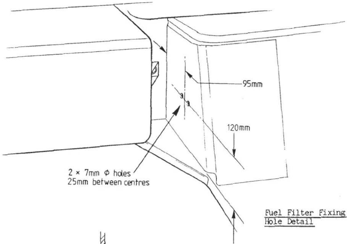

Fuel Filter Mounting
Key to Fuel System Diagram
-
LH Fuel Tank
-
RH Fuel Tank
-
LH Tank Top Board
-
RH Tank Top Board
-
Bracket, Board to Bulkhead
-
Studplate, Bracket to Bulkhead
-
Washer Plate
-
Bracket, Board to Wheelarch
-
Washer Plate
-
Washer Plate
-
Foam, Tank Clamping
-
Sender Unit, Fuel Gauge
-
Gasket, Sender Unit
-
LH Filler Neck
-
RH Filler Neck
-
Filler Cap
-
Clamp Ring, Filler Neck
-
Gasket, Clamp Ring
-
Hose, Filler to Tank
-
Hose Clip
-
Vent Hose, Tank to Neck
-
Hose Clip
-
Breather Hose, 260 mm
-
Anti-Surge Valve
-
Breather Hose 200 mm
-
Breather Hose 2 m
-
'T' Piece
-
Breather Hose 3.2 m
-
'P' Clip
-
Hose, Tank Crossover
-
Hose Clip
-
Crossover Pipe
-
Grommet, c/o Pipe
-
Grammet, c/o Pipe
-
Ring, Grommet Fixing
-
Fuel Feed Banjo
-
Fuel Return Banjo
-
Copper Washer, Banjo
-
Crush Washer, Banjo
-
Banjo Bolt
-
Fuel Pipe, Tank to Pump
-
Clip, Fuel Pipe
-
Grommet, Fuel Pipe
-
Fuel Pump
-
Insulator Strip
-
Fuel Pump Clamp
-
Clamping Bolt
-
Plain Washer
-
Nyloc Nut
-
Bolt, Clamp to Chassis
-
Washer
-
Fuel Pipe, Pump to Filter
-
Clip, Fuel Pipe
-
Fuel Filter
-
Insulator Strip
-
Fuel Filter Clamp
-
Clamping Bolt
-
Plain Washer
-
Nyloc Nut
-
Studplate, Filter Clamp
-
Fuel Pipe, Filter to Bundy
-
Clip, Fuel Pipe
-
Fuel Bundy Pipe
-
Fuel Pipe, Bundy to P.R.V.
-
Fuel Pipe, Return
-
'P' Clip
-
Grommet, Return Pipe
-
Fuel Pressure Regulating Valve
-
Screw, P.R.V. Fixing
-
Spring Washer
-
Fuel Pipe, P.R.V. to Rear Carb
-
Fuel Pipe, P.R.V. to Front Carb
-
Adaptor, Fuel Pipe to Carb
-
Filter, Carb Inlet
-
Sealing Washer
-
Pressure Hose, P.R.V. to Banjo
-
Banjo, Rear Carb
-
Washer, Large
-
Washer, Small
-
Bolt, Bonjo
-
Hose, Banjo to Diffuser
FUEL SYSTEM
SECTION LB - ESPRIT TURBO, DOM/ROW
| Operation | Page | |
| General Description | LB1 | 2 to 4 |
| Carburettor Theory of Operation | LB2 | 4 to 8 |
| Float Level Checking | LB3 | 9 |
| Carburettor Balancing Procedure | LB4 | 9/10 |
| Carburettor Mounting | LB5 | 10 |
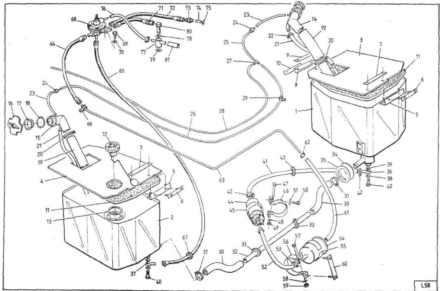
Page 2
SECTION LB

LB.1.-GENERAL DESCRIPTION
Two fuel tanks are fitted, one ahead of each rear wheelarch. A separate filler neck with lockable cap is provided for each tank, and the two tanks are interconnected by a large bore balance pipe. A single sender unit for the fuel gauge is fitted into the top of the right hand tank.
Fuel is fed from the left hand tank to a high pressure turbine type fuel pump capable of delivering 100 litres/hour. Fuel is then fed through a canister filter, also fitted beneath the left hand front corner of the engine bay, and then to the fuel pressure regulating valve mounted on the rear of the carburettor plenum chamber.
A spring and diaphragm system in the regulating valve, is adjusted to set fuel pressure to 3.5 lb/in 2 during idle and light load conditions, but as inlet boost pressure is developed, a sensing pipe from the diffuser (via the rear carb. cold start banjo) adds a boost pressure signal to the spring pressure to ensure that fuel pressure is maintained at 3.5 lb/in 2 above boost pressure.
Excess fuel supplied to the regulating valve is returned via a port in the bottom of the valve to the right hand tank, whilst two separate pipes from the valve carry fuel to the front and rear carburettors.
Fuel from the union (1) passes through the filter (2) and reaches the needle valve seat (18), where the needle valve (17), attached to the float (15), controls the fuel flow into the float chamber, thereby maintaining a constant level.
The float chamber is vented to the plenum chamber through the hole (4) in the chamber (3).

Starting
With the choke valve (8) opened, fuel metered through jet (14), passes into the emulsion tube (13), where it mixes with air from the channel (16), communicating with the float chamber top through hole (6).
The mixture formed flows, through holes (7), into the valve chamber (9), further mixing with air from the two channels (5).
From the valve chamber (9), mixture is divided into the two channels (10) which lead into the main barrels (11) downstream of the throttle valves (12).
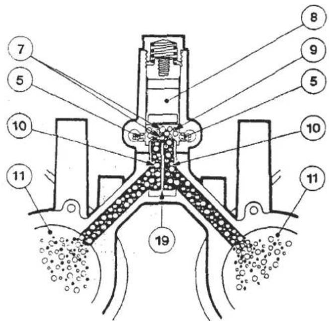
With the choke valve (8) partially closed, when a leaner mixture is required, mixture flows into the valve chamber (9) through one of the two outlet ports (7), further mixing with air from the two channels (5), which, in this condition, are partially closed.
With the choke valve (8) closed, communication between the main barrels and the starting circuit is cut off as is also communication between the two barrels by means of the dividing bushing (19).
Idling
Fuel coming from the float chamber, metered by the idle jets (21), mixes with the air from the well (23) through channels (22); the mixture thus formed, through channels (24) arrives to the adjustment screw (27) and then, metered, flows into the main barrels (11) downstream the throttle valve (12).
Replacing the plug (26) with an adaptor connected to a suitable manometer, it is possible to check, through channel (28) the pressure existing in the barrels (11) with throttle valve (12) in idling position and equalize the air flow adjusting the bypass screw (25) which controls the hole (29).

SECTION LB
Progression
On first opening the throttle valves (12), that is when passing from idle to full throttle, mixture arrives to barrels (11) also through progression holes (32).

Acceleration
On opening of throttle valves (12), lever (39) attached to spindle (38), by means of the rod (40) and the spring (41) pushes the pumplever (43) which acts directly on the diaphragm (44) held out by the spring (45).
Moving of the diaphragm (44) causes delivery of fuel to the main barrels (11) through the respective valves (36) and jets (37).
On closing of throttle valves (12), diaphragm (44) returns to the original position pushed by the spring (45) and draws fresh fuel from the fuel well (33) through the valve (35).
The ball valve (34) ensures that the pump circuit is cut off when the turbocharger starts operating.
The pump injection quantity can be changed by adjusting nut (42).

Full Throttle
With the throttle valves (12 opened, fuel from the float chamber (46) metered by the jets (47), enters the well (48) and mixes with air metered by the air corrector (49).
The mixture thus formed, passes through the inner venturi (50) where it further mixes with air drawn through the main barrel of the carburettor, flows into the venturis (51) and then, through the main barrels (11) reaches the engine.
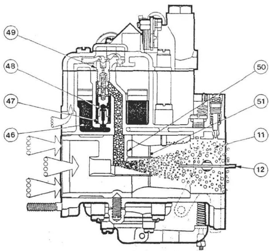
LB.3. - FLOAT LEVEL CHECKING
Remove the carburettor top complete with float assembly. Ensure the correct weight of 8.5 g is indicated on the float, and that the float assembly pivots freely on its pin. Hold the cover vertical with the float hanging downwards and in light contact with the needle.
Measure the dimension 'A' between float and gasket as shown in the diagram, for each float of the assembly, and if necessary carefully bend the float arm at 'B' to correct.

LB.4.- CARBURETTOR BALANCING PROCEDURE
- Ensure ignition timing is correct and the air filter and all trunking etc. fitted.
- Remove anti-tamper caps from idle CO adjustment screws and balancing screws.
- Replace vacuum tapping screws with manometer adaptors T000T0496 and correct to manometer T000T0499.
- Fully close all balancing screws (do not graunch).
- Set idle CO adjustment screws 6 × 1/2 turns open, and start engine.
- With engine at normal running temperature with ACU off and cooling fans on, adjust throttle stop screw to give specified idle speed of 850 rpm.
-
Adjust throttle coupling screw to balance lower of mercury columns 1 and 2 with lower of mercury columns 3 & 4, to within 3 mm.
-
Considering the front carburettor, gradually unscrew the air bleed balancing screw of ONLY the carburettor barrel with the highest mercury column, until it is balanced with the lower column to within 3 mm.
-
Carry out the same procedure for the rear carburettor, and if necessary re-adjust the throttle coupling screw to balance all columns to within 3 mm. Ensure correct idle speed is maintained.
-
Connect exhaust gas analyser to the inboard (Turbine) exhaust tailpipe and note 'CO' and 'HC' readings. Screw down each idle CO adjustment screw in turn until 'HC' reading starts to increase, then return (unscrew) again by a 1/4 turn. 'HC', as hexane, should normally be not more than 400 ppm. CO maximum is 1.0%. Maintain idle speed and manometer balance throughout.
-
Disconnect manometer and adaptors and replace blanking screws. Fit new anti-tamper caps where necessary. Ensure all fuel pipe connections are secure.
LB.5.-CARBURETTOR MOUNTING
The spacer plates and 'O' rings used at this joint act as insulators to absorb vibration and prevent frothing of fuel in the float chambers. It is essential that the carburettor mountings are not overtightened, as the 'O' rings may be displaced with a resultant air leak.
A uniform 1.5 - 2.0 mm gap must be maintained between carburettor and spacer plate, and between spacer plate and manifold as shown.

FUEL SYSTEM
SECTION LC - U.S.A. ESPRIT TURBO - CARBURETTOR
| Operation | Page | |
| General Description | LC1 | 2 to 4 |
| Carburettor Theory of Operation | LC2 | 4 to 9 |
| Fuel Control Pressure | LC3 | 10/11 |
| Float Level Checking | LC4 | 11 |
| Carburettor Balancing Procedure | LC5 | 12/13 |
| Carburettor Mounting | LC6 | 13 |

Page 2
SECTION LC

Key to Fuel System Diagram
- LH Fuel Tank
- RH Fuel Tank
- LH Tank Top Board
- RH Tank Top Board
- Bracket, Board to Bulkhead
- Studplate, Bracket to Bulkhead
- Washer Plate
- Bracket, Board to Wheelarch
- Washer Plate
- Washer Plate
- Foam, Tank Clamping
- Sender Unit, Fuel Gauge
- Gasket, Sender Unit
- LH Filler Neck
- RH Filler Neck
- Filler Cap
- Clamp Ring, Filler Neck
- Gasket, Clamp Ring
- Hose, Filler to Tank
- Hose Clip
- Vent Hose, Tank to Neck
- Hose Clip
- Breather Hose, 260 mm
- Anti-Surge Valve
- Breather Hose 200 mm
- Breather Hose 2 m
-
'T' Piece
-
Breather Hose 3.2 m
- 'P' Clip
- Hose, Tank Crossover
- Hose Clip
- Crossover Pipe
- Grommet, c/o Pipe
- Grammet, c/o Pipe
- Ring, Grommet Fixing
- Fuel Feed Banjo
- Fuel Return Banjo
- Copper Washer, Banjo
- Crush Washer, Banjo
- Banjo Bolt
- Fuel Pipe, Tank to Pump
- Clip, Fuel Pipe
- Grommet, Fuel Pipe
- Fuel Pump
- Insulator Strip
- Fuel Pump Clamp
- Clamping Bolt
- Plain Washer
- Nylac Nut
- Bolt, Clamp to Chassis
- Washer
- Fuel Pipe, Pump to Filter
- Clip, Fuel Pipe
-
Fuel Filter
-
Insulator Strip
- Fuel Filter Clamp
- Clamping Bolt
- Plain Washer
- Nyloc Nut
- Studplate, Filter Clamp
- Fuel Pipe, Filter to Bundy
- Clip, Fuel Pipe
- Fuel Bundy Pipe
- Fuel Pipe, Bundy to P.R.V.
- Fuel Pipe, Return
- 'P' Clip
- Grommet, Return Pipe
- Fuel Pressure Regulating Valve
- Screw, P.R.V. Fixing
- Spring Washer
- Fuel Pipe, P.R.V. to Rear Carb
- Fuel Pipe, P.R.V. to Front Carb
LC.1 - GENERAL DESCRIPTION
Two fuel tanks are fitted, one ahead of each rear wheelarch. A separate filler neck with lockable cap is provided for each tank, and the two tanks are interconnected by a large bore balance pipe. A single sender unit for the fuel gauge is fitted into the top of the right hand tank.
Fuel is fed from the left hand tank to a high pressure turbine type fuel pump capable of delivering 100 litres/hour. Fuel is then fed through a canister filter also fitted beneath the left hand front corner of the engine bay, and then to the fuel pressure regulating valve mounted on the rear of the carburettor plenum chamber.
A spring and diaphragm system in the regulating valve is adjusted to set fuel pressure to 4.0 - 4.5 lb/in 2 under light load conditions, but as inlet boost pressure is developed, a sensing pipe from the plenum chamber adds a boost pressure signal to the spring pressure to ensure that fuel pressure is maintained at 4.0 - 4.5 lb/in 2 above boost pressure. However, a micro-switch mounted on the front of the front carburettor and operated by the throttle lever in its fully closed position energises the fuel pressure solenoid, fitted beneath the rear of the plenum chamber. The signal to the fuel pressure regulator is then switched to number one cylinder inlet manifold depression, thus reducing fuel pressure to the carburettors and mixture strength under closed throttle 'overun' conditions.
Excess fuel supplied to the regulating valve is returned via a port in the bottom of the valve to the right hand tank, whilst two separate pipes from the valve, carry fuel to the front and rear carburettors.
LC.2 - CARBURETTOR THEORY OF OPERATION
Carburettor Type - Dellorto DHLA 45M (2 off)
Fuel Supply
Fuel from the union (1) passes through the filter (2) and reaches the needle valve seat (18), where the needle valve (17), attached to the float (15), controls the fuel flow into the float chamber, thereby maintaining a constant level.
The float chamber is vented to the plenum chamber through the hole (4) in the chamber (3).
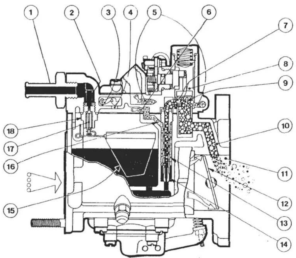
Starting
With the choke valve (8) opened, fuel metered through jet (14), passes into the emulsion tube (13), where it mixes with air from the channel (16), communicating with the float chamber top through hole (6).
The mixture formed flows, through holes (7), into the valve chamber (9), further mixing with air from the two channels (5).
From the valve chamber (9),
mixture is divided into the two channels (10) which lead into the main barrels (11) downstream of the throttle valves (12).

With the choke valve (8) partially closed, when a leaner mixture is required, mixture flows into the valve chamber (9) through one of the two outlets ports (7), further mixing with air from the two channels (5), which, in this condition, are partially closed.
With the choke valve (8) closed, communication between the main barrels and the starting circuit is cut off as is also communication between the two barrels by means of the dividing bushing (19).
Idling
Fuel coming from the float chamber, metered by the idle jets (21), mixes with the air from the well (23) through channels (22); the mixture thus formed through channels (24) arrives to the adjustment screw (27) and then, metred, flows into the main barrels (11) downstream the throttle valve (12).
Replacing the plug (26) with an adaptor connected to a suitable manometer, it is possible to check, through channel (28) the pressure existing in the barrels (11) with throttle valve (12) in idling position and equalize the air flow adjusting the bypass screw (25) which controls the hole (29).
The vacuum advance is connected through the calibrated hole (31) by the union (30). Screw (20) adjusts opening of the throttle valves at idle.

SECTION LC
Progression
On first opening the throttle valves (12), that is when passing from idle to full throttle, mixture arrives to barrels (11) also through progression holes (32).

Acceleration
On opening of throttle valves (12), lever (39) attached to spindle (38), by means of the rod (40) and the spring (41) pushes the pump lever (43) which acts directly on the diaphragm (44) held out by the spring (45).
Moving of the diaphragm (44) causes delivery of fuel to the main barrels (11) through the respective valves (36) and jets (37).
On closing of throttle valves (12), diaphragm (44) returns to the original position pushed by the spring (45) and draws fresh fuel from the fuel well (33) through the valve (35).
The ball valve (34) ensures that the pump circuit is cut off when the turbocharger starts operating.
The clearance between pump diaphragm and lever can be adjusted by nut (42).

Whereas on Domestic/RoW Turbo and 912 engine carburettors the volume of fuel delivered by the accelerator pump is adjusted by nut (42), on Federal Turbo DHLA 45M carburettors, the volume delivered is fixed, but the point of delivery commencement is adjustable. The correct setting is such that with the throttle closed, there is a clearance of 0.6 ± 0.1mm between the end of the pump lever and the diaphragm plunger.
Full Throttle
With the throttle valves (12) opened, fuel from the float chamber (46) metered by the jets (47), enters the well (48) and mixes with air metered by the air corrector (49).
The mixture thus formed, passes through the inner venturi (50) where it further mixes with air drawn through the main barrel of the carburettor, flows into the venturis (51) and then, through the main barrels (11) reaches the engine.

Power Jet Operation
At high engine speeds, an additional amount of mixture flows through the needle jet (52), upstream the inner venturi (50); mixture is composed of fuel drawn from the float chamber through channel (56) and metered by the jet (55), mixed with air metered by the calibrated passage (54) and drawn from the float chamber top (53).

LC.3 - FUEL CONTROL PRESSURE
- Connect fuel pressure test gauge as shown below.

Switch on ignition and check fuel pressure = 4.0 - 4.5 p.s.i. If outside specification, remove anti-tamper plug from fuel pressure regulator adjustment screw, and adjust as necessary.
If the pressure reading is too high, and cannot readily be adjusted to specification, a restriction in the return line is indicated. Rectify as necessary.
If the pressure reading is too low, and cannot readily be adjusted to specification, a restriction in the supply line, or faulty fuel pump is indicated.
Check for an unrestricted supply to the fuel pump, and for fuel filter restriction. Test fuel pump
- Start engine and allow to reach normal running temperature.
Check fuel pressure at the regulator. This should be lower than 3.5 p.si. at idle (950 ± 50 rpm). If above specification, check that the micro-switch on the front of the front carburettor is activated. If not, rotate the switch down towards the lever until switch contact is made.
View from front

If switch adjustment is carried out, open throttle to 2500 rpm and then return throttle to idle position. Check that when engine speed is above 1800 rpm, the micro-switch is deactivated allowing fuel pressure to increase to 4.0 - 5.0 p.s.i. Repeat this test and check that pressure differences are maintained. Adjust switch position if necessary but always ensure that idle pressure requirements are met.
If switch contact is made at idle, but fuel pressure remains above 3.5 p.s.i, check fuel pressure regulator solenoid pipework and wiring for leakage or disconnection. If no fault is found, replace fuel pressure regulator solenoid valve.
LC.4 - FLOAT LEVEL CHECKING
Remove the carburettor top complete with float assembly. Ensure the correct weight of 8.5 g is indicated on the float, and that the float assembly pivots freely on its pin. Hold the cover vertical with the float hanging downwards and in light contact with the needle.
Measure the dimension 'A' between float and gasket as shown in the diagram, for each float of the assembly, and if necessary carefully bend float arm at 'B' to correct.

LC.5 - CARBURETTOR BALANCING PROCEDURE
- Ensure ignition timing is correct and the air filter and all trunking etc, fitted.
- Remove anti-tamper caps from idle CO adjustment screws, air bleed balancing screws, and throttle coupling screws.

- Replace vacuum tapping screws with manometer adaptors T000T0496 and connect to manometer T000T0499. Fit exhaust probe to exhaust outlet pipe of turbocharger and connect to CO/HC analyser (e.g. Sun EPA 75 or equivalent).
- Fully close all balancing screws (do not 'graunch').
- Set idle CO adjustment screws 6 × 1/2 turns open, and start engine.
- With engine at normal running temperature with ACU off and cooling fans on, adjust throttle stop screw to give specified idle speed of 950 ± 50 rpm.
- Adjust throttle coupling to balance lower of mercury columns 1 and 2 with lower of mercury columns 3 and 4 to within 3 mm, ensuring that the two coupling screws securely clamp against the throttle lever.
- Considering the front carburettor, gradually unscrew the air bleed balancing screw of ONLY the carburettor barrel with the highest mercury column, until it is balanced with the lower column to within 3 mm.
-
Carry out the same procedure for the rear carburettor, and if necessary re-adjust the throttle coupling to balance all columns to within 3 mm. Ensure correct idle speed is maintained.
-
Switch analyser to sample mode and check readings.
Note: Do not touch idle adjustment screws until CO reading has stabilised.
CO reading should be between 0.2 - 1.2%. If higher or lower levels are found, move each mixture screw 1/4 of a turn in or out as the reading dictates. Check the CO reading and repeat procedure until correct specification is achieved. A balance between CO and HC is required, and the Hexane level should be below 550 ppm for a 'new' engine and below 350 ppm for a 'run-in' engine.
- Disconnect manometer and adaptors, and replace blanking screws. Fit new anti-tamper caps where necessary. Ensure all fuel pipe connections are secure. Disconnect exhaust sample probe, and refit blanking plug securely.
LC.6 - CARBURETTOR MOUNTING
The spacer plates and 'O' rings used at this joint act as insulators to absorb vibration and prevent frothing of fuel in the float chambers. It is essential that the carburettor mountings are not overtightened, as the 'O' rings may be displaced with a resultant air leak.
A uniform gap must be maintained between carburettor and spacer plate, and between spacer plate and manifold as shown.


FUEL SYSTEM
SECTION LD - USA ESPRIT TURBO H.C.I.
| Operation | Page | |
| General Description | LD.1 | 2 to 5 |
| Fuel Injection System Description | LD.2 | 5 |
| Fuel Feed (pumps, accumulator, filter) | LD.3 | 5 to 7 |
| Mixture Control Unit | LD.4 | 7 to 11 |
| Fuel Injectors | LD.5 | 12 |
| Mixture Adaptation | LD.6 | 13 |
| Cold Start Injector | LD.7 | 13 |
| Thermal Time Switch | LD.8 | 14 |
| Auxiliary Air Valve | LD.9 | 14/15 |
| Warm Up Regulator | LD.10 | 15 |
| High Altitude Compensation | LD.11 | 16 |
| Exhaust Emission Control | LD.12 | 16 |
| Lambda Sensor | LD.13 | 17 |
| Frequency Valve | LD.14 | 17/18 |
| Electronic Control Unit | LD.15 | 18/19 |
| Fuel By-Pass Valve | LD.16 | 19 |
| Vacuum Operated Engine Management Devices | LD.18 | 20 to 23 |
| Air Cond. Idle Up Solenoid | LD.19 | 20 |
| Evaporative Loss System | LD.20 | 24/25 |
| Engine Warm Up Summary | LD.21 | 26 |
| Fuel System Precautions | LD.22 | 26 |
| Engine Management System Check/Set Up Procedure | LD.23 | 27 to 30 |
| Fault Diagnosis | LD.24 | 31 |
| Torque Settings, Fuel Injection | LD.25 | 51 |
| Ignition Box Component Location | LD.26 | 52 |
| Wiring Diagram Schematics, Fuel Injection | LD.27 | 53 to 65 |
| Electrical Component, Function & Fault Diagnosis | LD.28 | 66 to 72 |
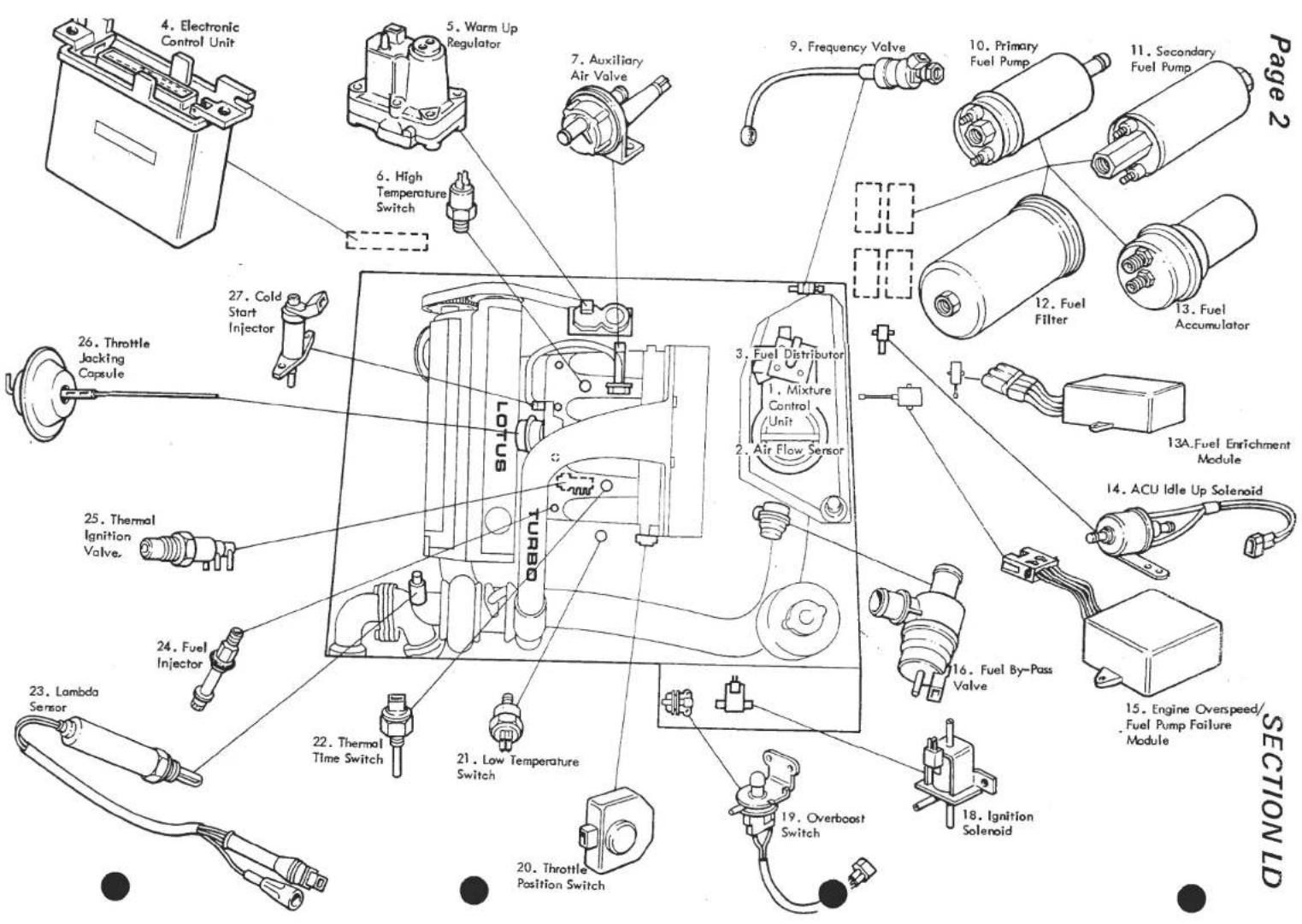
FUNCTION INJECTION COMPONENT FUNCTION

LD
- Mixture Control Unit Comprises of the Air Flow Sensor and Fuel Distributor. (LD.4)
- Air Flow Sensor Measures air flow into the engine and moves fuel distributor control valve accordingly.
- Fuel Distributor Comprises:
i) Primary Pressure Regulator to control pressure of fuel delivered by pumps.
ii) Control valve to regulate fuel delivered to injectors dependent on air flow.
iii) Four Distributor Differential Valves to maintain constant pressure drop across each control valve slit.
- Electronic Control Unit (E.C.U.) Controls Frequency Valve cycle rate. (LD.15)
- Warm Up Regulator Enrichens air/fuel ratio during engine warm up. Compensates for high altitude conditions. (LD.10)
- High Temperature Switch Switches Ignition Solenoid at water temperatures below 70°C (increased ignition advance) (LD.18)
-
Auxiliary Air Valve Supplies extra air (and fuel) to cold engine to improve driveability and idling (LD.9)
-
Frequency Valve Amends mixture strength dependent on exhaust oxygen content to reduce harmful emissions. (LD.14)
10/ Fuel Pumps Feed fuel from the tanks to the fuel distributor
11. (LD.3)
12. Fuel Filter Protects system from impurities. (LD.3)
13. Fuel Accumulator Maintains fuel system pressure after engine switch off to aid re-starting. (LD.3)
13A. Fuel Enrichment Module Supplies signal to E.C.U. (enrichment) at engine speeds over 3250 rpm (LD.15)
14. A.C.U. Idle Up Solenoid Maintains idle speed when air conditioning is operating. (LD.19)
15. Engine Overspeed/Fuel Pump Failure Module Limits normal max. rpm to 7,000 reducing to 2,800 if one fuel pump fails (LD.3)
16. Fuel By-Pass Valve Allows air to by-pass Airflow Sensor, thus shutting off fuel supply, on closed throttle engine overun conditions (LD.16)
18. Ignition Solenoid Operates Throttle Jacking Capsule at water temperatures below 60°C (increased idle speed). (LD.18)
19. Overboost Switch Cuts out fuel pumps if overboost is detected (LD.3)
20. Throttle Position Switch Switches a signal to the electronic control unit and engine management system at idle, off idle to 30° throttle, and over 30° throttle opening. (LD.15,16)
21. Low Temperature Switch makes on fall below 25° C oil temp. and switches E.C.U. for cold enrichment. Breaks on rise @ 35° C (LD, 15)
22. Thermal Time Switch Regulates cold start injection time dependent on water temperature. (LD.8)
23. Lambda Sensor Senses oxygen content in exhaust for Frequency Valve. (LD.13)
24. Fuel Injector One in each manifold port, continuously inject fuel supplied by distributor. Surrounded by air stream. (LD.5)
25. Thermal Ignition Valve Increases ignition advance at water temperature below 53° C (cold driveability). (LD.18)
26. Throttle Jacking Capsule Increases cold engine idle speed (LD.18)
27. Cold Start Injector Supplies cold engine with extra fuel for short period whilst cranking to aid starting. (LD.7)
ω
![graph TD A["COMPRESSOR"] --> B["AUXILIARY AIR VALVE"] B --> C["INJECTOR"] C --> D["COLD START INJECTOR"] D --> E["COLD START RAIL"] E --> F["LOW TEMP SWITCH"] F --> G["THermo TIME SWITCH"] G --> H["HIGH TEMP SWITCH"] H --> I["FUEL BYPASS VALVE"] I --> J["AIR FLOW SENSOR"] J --> K["FUEL ACCUMULATOR"]…](/content/2026/05/1021120/images/54ae9fbbe40d025d0cb0f50d9d9085d4bf3f64162b7d52f625efb87d8a11aa80.jpg)
FUEL SYSTEM- SCHEMATIC DIAGRAM


LD.1.-GENERAL DESCRIPTION
Two fuel tanks are fitted, one ahead of each rear wheelarch. A separate filler neck with lockable cap is provided for each tank, and the two tanks are interconnected by a large bore balance pipe. A single sender unit for the fuel gauge is fitted into the top of the RH tank.
Fuel is fed from the RH tank through an integral strainer to the fuel pumps and injection system, with excess fuel being returned into the top of the RH tank.
Filling of the fuel tanks is best achieved by twisting the pump nozzle 45° to allow it to be inserted fully around the bend in the filler neck.
LD. 2. - FUEL INJECTION SYSTEM DESCRIPTION
Lotus fuel injection engines use a Bosch K-Jetronic system to provide an optimum air-fuel mixture under all operating conditions. The system is based on the principle of continuous injection of fuel into the intake port of each cylinder, and derives its designation 'K' from the German word for 'continuous'. The fuel injection may be said to operate mechanically, with the quantity of fuel delivered being regulated by the amount of air drawn in by the engine.
The basic system is regulated to provide the correct air/fuel ratio for normal running conditions, and full power running. Various supplementary devices are used to modify this ratio to achieve efficient overall performance when cold, decelerating, starting, idling, operation at high altitude etc.
An oxygen sensor in the exhaust system is used to determine the mixture strength being supplied to the engine, and an electronic control unit makes corrections accordingly.
LD. 3. - FUEL FEED
The fuel feed system comprises the fuel pumps, fuel accumulator, and fuel filter. All these components are fitted at the RH front underside of the engine bay.
Fuel Pumps Two fuel pumps, connected in series, draw fuel from the RH petrol tank and supply it via the fuel accumulator and filter to the fuel distributor. Both pumps are fitted with non-return valves in their outlet connections.

Electric Fuel Pump
- Fuel Intake
- Excess Pressure Valve
- Roller-Cell Pump
- Electric Motor Armature
- Non-Return Valve
- Fuel Outlet
The pumps are permanent magnet electric motor roller-cell type, wherein the fuel flows past the motor itself to a roller cell pump chamber. A motor driven disc mounted eccentrically in this chamber, uses rollers contained in slots around its circumference and thrown out by centrifugal force against the wall of the eccentric chamber, to transfer fuel from the motor side of the chamber into the fuel feed pipeline.

Roller-Cell Pump
-
Fuel Intake
-
Rotor Disc

-
Roller
-
Pump Housing
-
Fuel Outlet
The lack of an ignitable air/fuel mixture in the pump prevents any explosion. The pumps operate whilst the engine is cranking or running, but do not operate in the stalled engine condition. The combined output of both pumps is more than the maximum requirement of the engine, excess fuel being returned to the tank via the primary pressure regulator. In order to protect the engine from damage if one pump fails, the engine overspeed/fuel pump failure module senses the failure and limits maximum engine speed to approx. 2,800 rpm by cutting out the remaining pump when this speed is reached.
The fuel pumps are also cut out if the Overboost Switch senses too great a boost pressure at the inlet manifold cold start air rail (i.e. exhaust wastegate failure).
Fuel Accumulator The fuel accumulator is fitted between the fuel pumps and fuel filter and is designed to maintain fuel pressure in the system after the engine has been switched off in order to aid re-starting and prevent vapour locks forming.
The accumulator also serves to deaden any noise arising from pulsations in the fuel line. The accumulator consists of a fuel storage chamber and spring loaded diaphragm.
Diagram A shows the storage chamber empty and the diaphragm pushed by its spring against the divider plate.

-
Spring Chamber
-
Storage
-
Spring
Chamber
-
Stop (full)
-
Baffle
-
Diaphragm
-
Fuel Entry
-
Fuel Exit
When the fuel pumps are running, the pressure of fuel pushes the diaphragm back against its spring until the storage chamber is filled as in diagram B.

When the pumps are switched off, the non-return valve fitted in the outlet of the second pump, prevents fuel returning to the tank, through the pumps, and the fuel distributor primary pressure regulator shuts off the fuel return pipeline.
The accumulator spring then maintains a rest pressure in the system for sufficient time to aid hot re-start.
Fuel Filter The fuel filter is fitted between the fuel accumulator and fuel distributor. Due to the extremely close tolerances of the injection equipment, a special fine filter is fitted to protect the system from impurities in the fuel.
The filter consists of a sealed cannister containing a paper filter element backed up by a lintor fluff filter, and a restraining strainer.

Fuel Filter
- Paper Element
- Lint or Fluff Filter
- Strainer
It is most important that the filter is fitted with the arrow stamped on the body pointing in the direction of fuel flow. The connections are arranged to permit only the correct fitment.
LD. 4. - MIXTURE CONTROL UNIT
The Mixture control unit is the heart of the fuel injection system, and comprises an air flow sensor and fuel distributor.
The air flow sensor is fitted between the air filter and turbocharger, and senses the amount of air being drawn into the engine. This measurement is used to move a control valve in the fuel distributor which regulates fuel delivery to the injectors.
Air Flow Sensor The air flow sensor consists of a sensor plate mounted on a counterbalanced lever, operating the fuel distributor control valve.
The sensor plate is positioned in an air funnel and operates on the suspended body principle such that the greater the quantity of air drawn in by the engine, the greater the sensor plate movement. The funnel is specially shaped to provide the necessary sensor plate movement and fuel delivery characteristics.

In order to prevent damage to the sensor in case of pressure shocks in the intake system (backfiring) etc.) provision is made for the sensor to swing upward and open a relief cross-section in the funnel before being restrained by a buffer. The rest position of the sensor is controlled by a preset spring pin.
The screw setting the fuel control valve operating arm is preset and requires no adjustment under normal operating conditions.
Fuel Distributor The fuel distributor comprises:
i) Primary Pressure Regulator (System Pressure)
iii) Four Distributor Differential Valves
i) Primary Pressure Regulator
The primary pressure regulator is incorporated into the body of the fuel distributor and takes the form of a spring loaded plunger.
Fuel is delivered by the pumps into the fuel distributor and exerts a force on the pressure regulator valve which is calibrated to maintain a primary fuel pressure of 6.0 Bar with excess fuel being returned to the tank.
A
A - Engine Stopped B - Engine Running
B

- Primary Pressure Input 4. Plunger
- Seal 5. Regulator Spring
- Return to Tank
When the engine is stopped, the fuel pumps are switched off and the pressure drops below injector opening pressure. The primary pressure regulator then seats fully under the action of its spring, and prevents further pressure reduction in the primary system.
The fuel control valve is located centrally in the fuel distributor, and controls the fuel delivery to the injectors relative to the air flow sensor position.

The control valve slides inside a barrel into which is fed fuel at primary pressure. The fuel then flows through 4 metering slits to the distributor differential valves and then to the fuel injectors. As the air flow sensor is deflected further by an increasing airflow, so the control valve is raised in its barrel, progressively opening a larger proportion of the metering slits, and increasing fuel flow to the injectors.
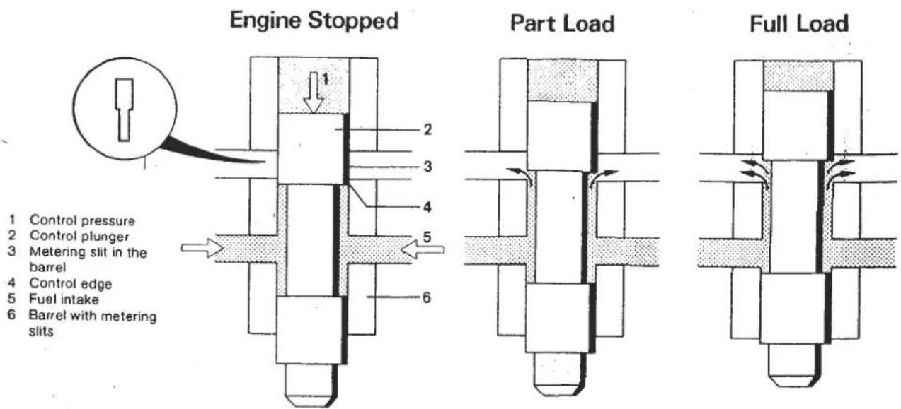
The Lotus fuel distributor has metering slits with two different widths, the smaller, standard section for light and part load running and the larger width for mid to full power running.
Control Pressure In order to damp any tendency of the control valve and air flow sensor to osillate, and to provide a means whereby the movement of the control valve relative to the airflow may be varied to suit different operation conditions, a 'control pressure' is arranged to act on the top of the control valve and oppose the force applied to it by the airflow sensor.

- Control Pressure Force
- Damping Restriction
- To Warm Up Regulator
- Control Pressure Take Off Orifice
- Fuel at Primary Pressure
- Force from Airflow Sensor
A small bore take off from the primary pressure supply directs fuel at a reduced pressure into the top of the fuel control valve cylinder. This 'control pressure' is regulated by the warm up regulator (see later) which reduces the control pressure when the engine is cold. This reduced force above the control valve, allows the airflow sensor and control valve to move a greater distance for a given airflow, and expose a greater proportion of the metering slits. More fuel then flows to the injectors to achieve a richer cold running mixture.
The warm up regulator achieves this control pressure regulation by allowing a proportion of the fuel to return to the tank, but in order to maintain control pressure after engine switch off, and to aid re-start, the return line from the warm up regulator is fitted with a shut off valve which closes when the engine is stopped.
A
Primary Pressure Regulator With Control Pressure Shut Off Valve
A - Engine Stopped
B - Engine Running

- Primary Pressure
- Return to Tank
- Plunger
- Shut Off Valve
- Control Pressure
This shut off valve is incorporated into the primary pressure regulators such that it is held open against spring pressure only whilst the primary pressure regulator is operating (i.e. engine running).
Distributor Differential Valves One distributor differential valve for each engine cylinder is incorporated in the fuel distributor to maintain a constant pressure drop across the metering slits regardless of their opening. This is necessary in order to ensure that the fuel flow to the injectors is dependant only on the length of metering slit exposed, and also is not affected by any variation in primary pressure.
The valves are mounted in 4 cavities inside the fuel distributor. Each cavity is divided into upper and lower chambers by a steel diaphragm. All the lower chambers are interconnected by a ring main and are supplied with fuel at primary pressure from the pumps. The upper chambers are isolated from each other and each is connected individually to one of the metering slits. Each diaphragm is spring loaded downwards away from a flat seat valve leading to one of the fuel injectors.

- Fuel Intake at
Primary Pressure - Upper Chamber
- To Fuel Injector
- Control Valve
- Metering Slit
- Helical Spring
- Steel Diaphragm
- Lower Chamber
LOW
FUEL
DELIVERY

HIGH
FUEL
DELIVERY

As the metering slit is opened, and the upper chamber pressure tends to increase, the diaphragm is pushed downwards increasing the flat seat valve opening to the injector line such that the upper chamber pressure remains at 0.1 bar below that of the lower chamber. This pressure differential is set by the helical spring. Hence, during operation, the diaphragm is held in equilibrium by the force of the primary fuel pressure on the underside, and by the upper chamber pressure plus the spring pressure on the topside
LD. 5. - FUEL INJECTORS
The fuel injectors are fitted into the inlet manifold, and continuously inject fuel into the intake parts whilst the engine is running.
The injectors have no metering function but open at a specified pressure and inject the fuel allocated to them by the fuel distributor.
The injector nozzles are fitted with a valve needle which vibrates at high frequency as the fuel flow pressure lifts the valve on and off its seat, producing a finely atomised spray.
Fuel atomisation is further aided, especially at low engine speeds, by an air stream flowing around the injector. This air stream is supplied via a passageway running across the top of the inlet manifold, and a hose connecting with the intake plenum.
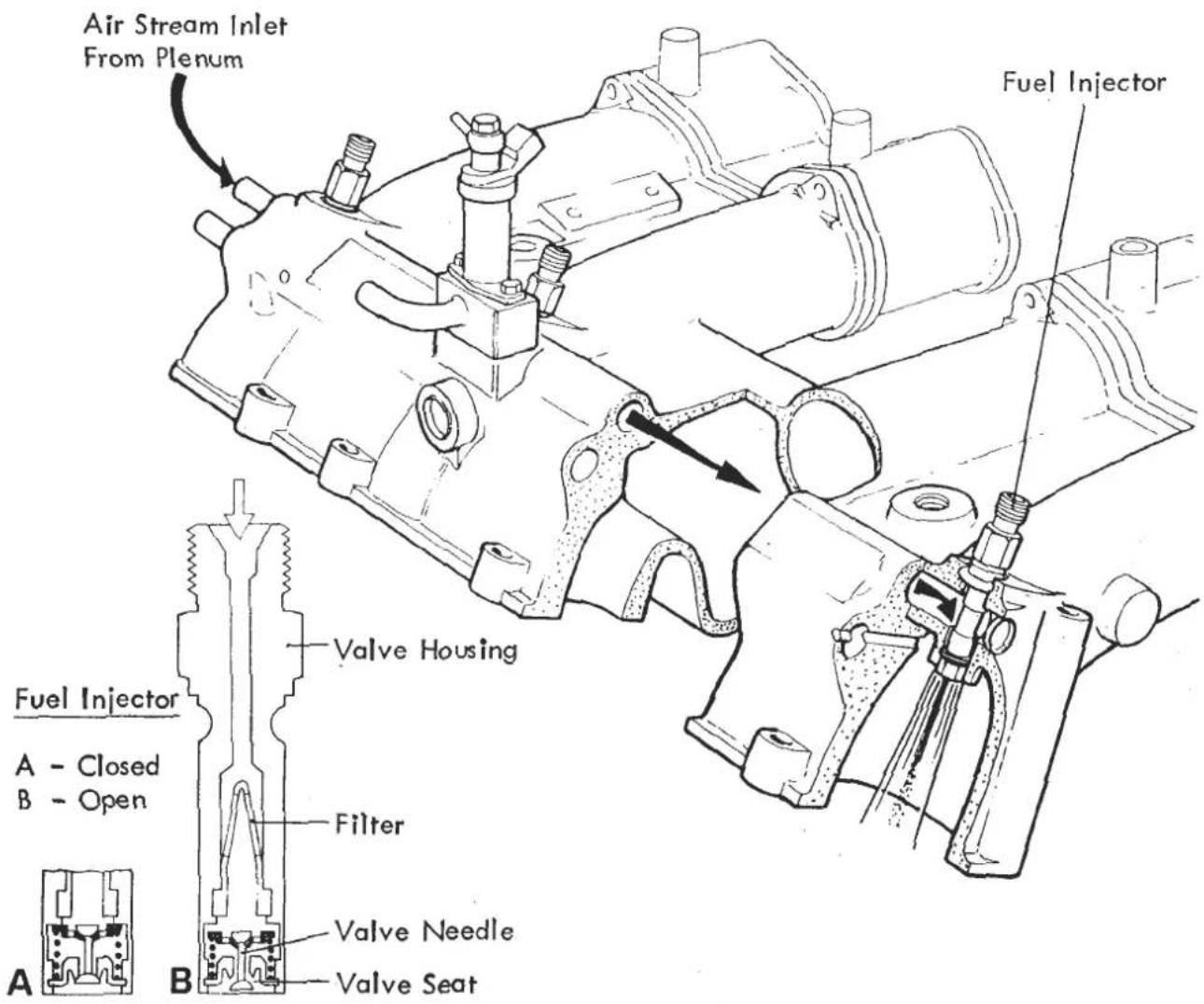
When the engine inlet valves are closed, the air/fuel vapour cloud formed, is stored in the intake port, to be drawn into the cylinder when the inlet valves open again.
When the engine is stopped, the fuel pressure drops below that required to open the injector valves, so shutting the valves and preventing fuel dripping into the ports.
LD. 6 - MIXTURE ADAPTATION
The system so far described provides a fuel/ air mixture suitable for normal running. Various supplementary devices are required in order to adapt the mixture strength for differing climatic, transient and emissions related conditions. These components include those providing enriched mixture strength for cold starting and running, fuel cut-off on overrun, and adjustment of mixture to achieve minimal harmful emissions.
LD. 7 - COLD START INJECTOR
When starting a cold engine, the cranking speed induces very low air flow with resulting low fuel delivery to the injectors. The additional fuel necessary for cold starting is supplied by the cold start injector only at cranking, and for a maximum duration of between 0.1 and 8.0 seconds dependant on coolant temperature.

The single cold start injector is fitted into an air rail running alongside the fuel injector air stream rail on the inlet manifold. Connecting passages join this air rail with each intake tract. A hose from the auxiliary air valve allows a flow of air to be drawn around the cold start injector on engine cranking to finely atomise the fuel sprayed from its nozzle.
The cold start injector is a solenoid valve supplied with fuel at primary pressure from the fuel distributor, and is opened by a current supplied via, and for a time period governed by the thermal time switch.
LD. 8. - THERMAL TIME SWITCH
The thermal time switch is fitted into the inlet manifold water jacket between tracts 3 & 4. Its function is to control the injection time of the cold start injector dependent on engine temperature.
The switch consists of a hollow tube, inside which is mounted an electrical contact controlled by a bimetallic strip wound with a heating coil.
The current, supplied to the thermal time switch only whilst the engine is cranked, is passed through the heating coil, and switch contacts to the cold start injector. As the bimetal strip heats up, it bends and opens the contacts, shutting off the injector. Maximum injection time, at -20°C is approx. 8 secs. The warmer the engine is, the more heat is absorbed by the bimetal strip, so that a shorter electrical heating time is needed to break the contact. When the engine is at normal running temperature the switch absorbs sufficient heat to keep the contacts open rendering the cold start injector inoperative.
LD. 9 - AUXILIARY AIR VALVE
In order to overcome the increased friction present in a cold engine, and enable the engine to idle satisfactorily after cold start-up, an auxiliary air valve is fitted between the plenum chamber and cold start air rail to by-pass the throttle butterflies and provide an additional air flow to the engine. Since this air is drawn through the airflow sensor, additional fuel is injected accordingly.
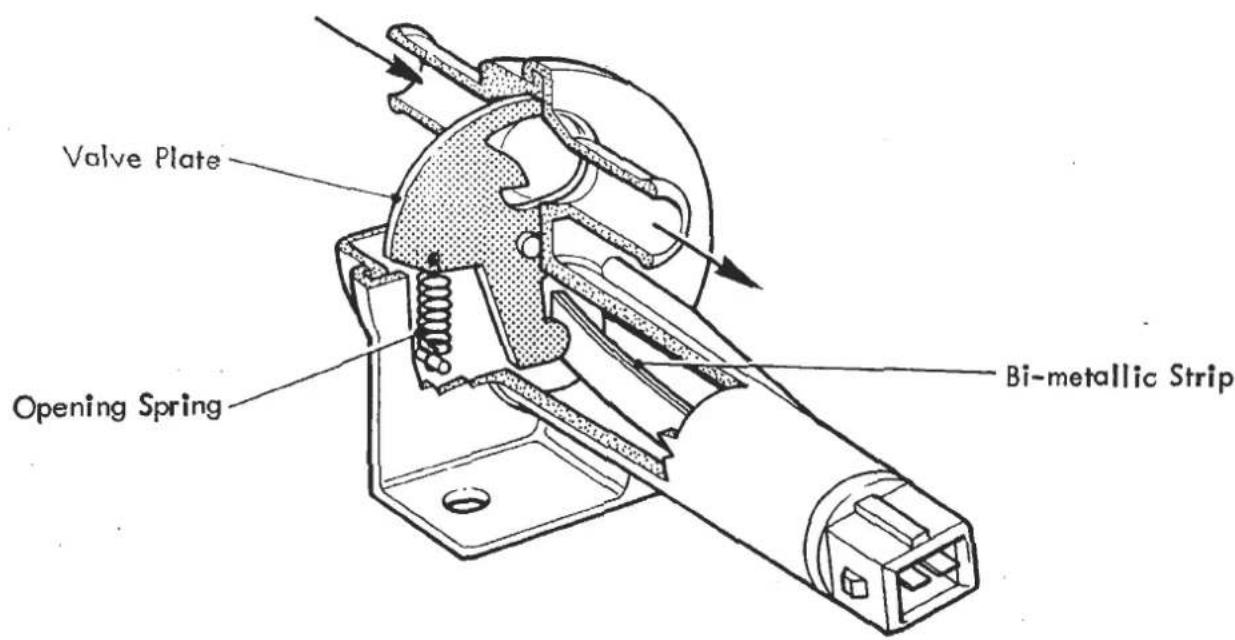
The auxiliary air valve consists of a pivoted plate provided with a specially shaped aperture such that by moving the plate the by-pass air supply line may be regulated between fully open and fully closed. Movement of the disc is controlled by an opening spring and a closing, heating coil wound, bimetal strip.

In the cold engine condition the plate adopts a position fully opening the by-pass line. As soon as the ignition is switched on, current flows through the heating coil and gradually causes the bimetal strip to bend and rotate the plate, reducing the by-pass aperture. As the engine warms, and its heat is absorbed by the valve body, the heating effect of the coil is augmented and the plate is rotated further to fully close the by-pass. Engine heat alone is sufficient to ensure that the by-pass remains closed when the engine is warm.
LD.10 - WARM UP REGULATOR
In order to compensate for the condensation of fuel on the inlet tract and cylinder walls whilst the engine is running cold, and to maintain driveability until normal running temperature is reached, it is necessary to enrich the fuel/air mixture during this period.
The warm up regulator fulfils this function by reducing the control pressure by an amount dependent on engine temperature. When the control pressure is reduced, the fuel control valve in the distributor is allowed to move further for a given airflow and open a greater proportion of the metering slits, increasing fuel flow to the injectors.


-
Valve Diaphragm
-
Return to Tank
-
Control Pressure
-
Valve Spring
-
Bimetal Spring
-
Heating Coil

-
Spring
-
Aneroic Capsule
The warm up regulator consists of a flat seat valve controlling the return of fuel from the control pressure line to the tank. The valve is held closed by a coil spring, but this is opposed by a bimetallic spring wound with a heating element which is fed with current whilst the ignition is switched on.
When cold, the bimetal spring overcomes the coil spring and opens the valve, such that the control pressure is low, and the mixture rich on engine start up. As the engine runs, the bimetal spring is heated, both by its heating coil, and by engine heat absorbed by the regulator, and gradually reduces its opening force on the valve. Finally, when the engine reaches normal running temperature, the bimetal spring is sufficiently heated to lift clear of the valve rod so that the control pressure is controlled only by the coil spring.
LD. 11. - HIGH ALTITUDE COMPENSATION
Operating the engine at high altitude where the air density is lower, requires that some compensation be made by the fuel metering system to prevent the mixture becoming too rich.
This compensation is achieved by incorporating an aneroic capsule into the base of the warm up regulator. The valve rod is extended to abut against the capsule, which is held in a 'flattened' condition by atmospheric pressure and a leaf spring as shown in the warm up regulator diagram. At high altitude, the reduced atmospheric pressure results in the aneroic capsule 'expanding' and exerting an additional closing force on the control pressure valve, raising the control pressure and compensating the mixture strength for altitude.
LD. 12 - EXHAUST EMISSION CONTROL
The minimum production of harmful exhaust gas emissions is achieved primarily through the use of starter and main 'three way' catalysts combined with very accurate fuel metering.
The optimum air/fuel ratio for minimum emission of all three noxious components - carbon monoxide CO, unburnt hydrocarbons HC, and nitrogen oxide NOx, and also for minimum fuel consumption with maximum driveability, is about 14 to 1 by weight. This is sometimes referred to as the 'stoichiometric ratio'.
The air/fuel ratio may also be represented by expressing the amount of air present in the mixture as a proportion of that amount required for a stoichiometric ratio. This proportion, the excess air factor, when used in connection with Bosch fuel injection, is referred to by the Greek letter Lambda (L). Thus, when Lambda (L) = 1, the correct amount of air is present, and the air/fuel ratio = 14 to 1.

When L is greater than 1, too much air is present and the mixture is lean. When L is less than one, too little air is present, and the mixture rich.
LD. 13 - LAMBDA SENSOR
It is possible to determine the excess air factor of the mixture being delivered to the cylinders by measuring the oxygen content of the exhaust gas before the catalyst. This is achieved by fitting a Lambda sensor into the exhaust system between the turbocharger and catalyst.
The Lambda sensor is calibrated such that deviations from L = 1 (the desired air/fuel ratio) result in a sudden change to its output voltage signal. This signal is used by an electronic control unit to determine the fuel delivery correction necessary. This correction is made via a 'Frequency Valve' fitted between the fuel distributor and tank. The sensor is fitted with its own heating coil which is used to heat the sensor to operating temperature after engine start up. Signals from the sensor are only processed at engine oil temperatures above 35° C.
LD. 14 - FREQUENCY VALVE (Timing Valve)
Corrections to the fuel delivery as determined by the Lambda sensor and electronic control unit (E.C.U.), are made by altering the fuel pressure beneath the diaphragms of the differential valves in the fuel distributor.
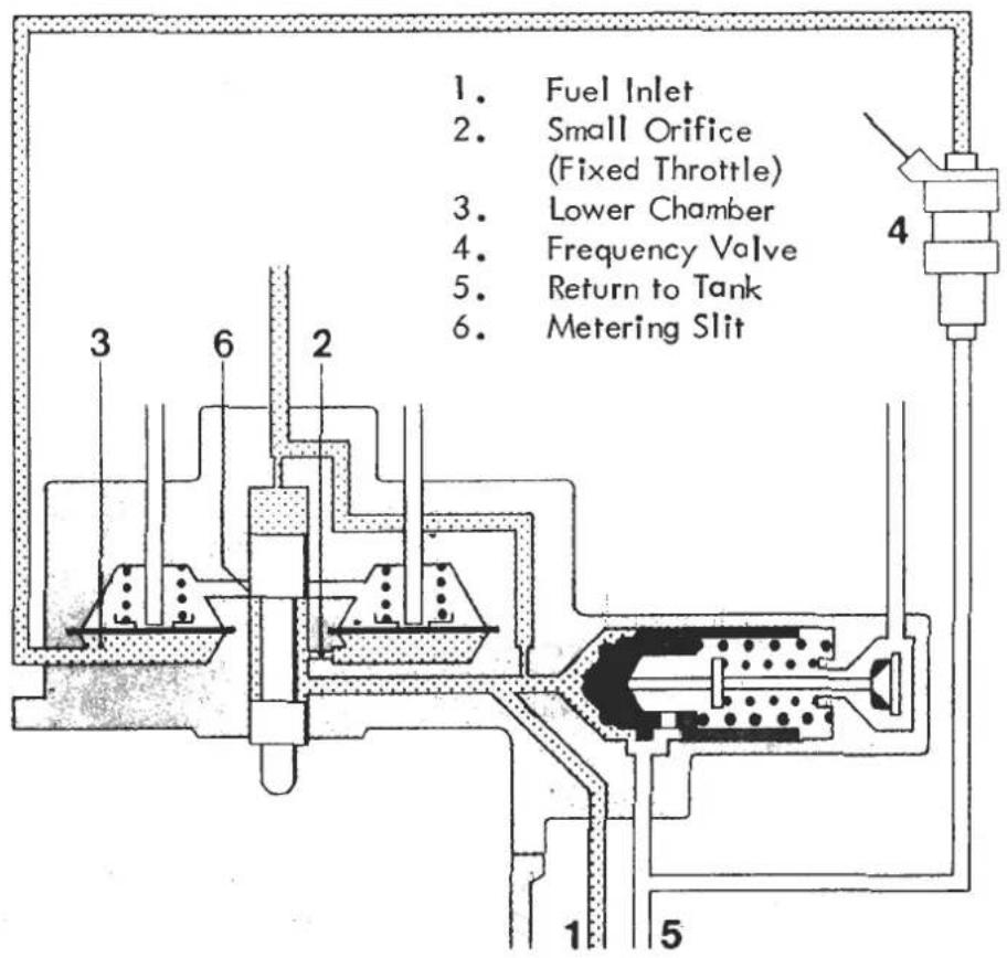
In order that the pressure in these lower chambers may be varied, the connection between their ring main and the regulated primary pressure is fitted with a small orifice (fixed throttle), and a return line from the lower chambers to the tank is provided with a variable throttle. In this way, if the variable throttle is closed, regulated primary pressure will be present in the lower chambers, whilst opening the variable throttle allows fuel in the lower chambers to bleed off back to the tank, hence lowering the pressure.
Lowering the pressure beneath the diaphragms will increase the pressure differential across the metering slits and increase fuel delivery to the injectors.
The variable throttle takes the form of a Frequency Valve, which continuously cycles open/closed, with the ratio between open and closed periods being determined by the electronic control unit.
LD. 15 - ELECTRONIC CONTROL UNIT (E.C.U.)
The function of the electronic control unit is to process information fed to it by various sensors including the exhaust gas Lambda sensor, and set an open/close ratio for the frequency valve.
This method of regulating the air/fuel ratio to Lambda = 1.0 by continuously monitoring exhaust gas oxygen content, is called Lambda closed loop control, and may be represented by the following flow chart.
![graph TD A["Lean mixture"] --> B["Rich mixture"] B --> C["Low sensor voltage"] C --> D["Regulated fuel pressure decreases"] D --> E["Injected fuel quantity increases"] E --> F["High sensor voltage"] F --> G["No Oxygen in exhaust gases"] G --> H["Open/close ratio of Frequency Valve is decreasing"] H…](/content/2026/05/1021120/images/25df521beb5cb51996beea16f6197baafd3dc4a905edd60292673fd76c52f411.jpg)
Certain operating conditions require different air/fuel ratios, and it is necessary to switch to an open loop control system with a preset frequency valve open/close ratio.
The open/close ratio of the solenoid operated frequency valve is controlled by an electrical pulse sent to open the valve many times a second. Under normal running conditions, the valve is opened for about 50% of the time, and the pulse rate supplied to it is referred to as 50% duty cycle. 100% duty cycle would mean the valve is held permanently open.
The E.C.U. sets fixed duty cycles under the following conditions:
i) 75% duty cycle at engine oil temperatures below 35° C as sensed by the the low temperature switch.
ii) 65% duty cycle on engine overrun, when fuel by-pass valve (LD.16) is operating.
iii) 65% duty cycle at throttle butterfly openings of more than 30°, as sensed by the throttle position switch.
iv) 65% duty cycle at engine speeds higher than 3250 rpm as sensed by 'fuel enrichment module' mounted on RH fuel tank board.
v) 50% duty cycle if a defect in the Lambda sensor is detected (unless conditions i, ii, iii or iv above apply).
At idle speed, the E.C.U. updates the closed loop duty cycle rate more quickly in order to stabilize idle rpm.
LD. 16 - FUEL BY-PASS VALVE
The fuel shut off valve has been incorporated into the fuel system to improve economy during engine overrun by returning the air sensor plate to its rest position, shutting off the fuel supply. This is achieved by collapsing the depression below the sensor plate by allowing air from the air cleaner housing to be fed directly into the air ducting below the plate.
The valve is controlled by an electric power supply and manifold vacuum but governed by the engine coolant temperature, engine speed and the position of the throttle. The valve has an air inlet and outlet with the inlet spigot pressed into a grommet in the air cleaner main body while the outlet is connected by hose to the air flow sensor lower housing. When the valve is triggered to its open position air will be drawn through the valve into the lower housing collapsing the vacuum below the plate. The sensor plate movement will be restored as soon as the valve closes.
The following conditions must occur for the valve to be activated:
The coolant temperature, sensed by the high temperature switch must be above 70°C. This is to ensure that the driveability is not affected during engine warm up.
The throttle must be 'closed'. A throttle position switch controls this operation ensuring that the by-pass valve only operates in the idle position.
The engine must be decelerating from a speed greater than 1600 rpm. Two critical speeds control the valve operation. It will not be activated unless the engine is decelerating from above 1600 rpm and it will cut out once the speed drops down to 1400 rpm. The engine speeds are monitored by a speed sensing relay, mounted in the ignition box at the rear of the engine bay.
LD. 18 - VACUUM OPERATED ENGINE MANAGEMENT DEVICES
These include the Thermal Ignition Valve, (T.I.V.) Ignition Solenoid, and Throttle Jacking Capsule.
Thermal Ignition Valve (T.I.V.)
The T.I.V. is fitted into the inlet manifold water rail and controls the vacuum feed to the distributor advance capsule (D.A.C.). At water temperatures below 53°C, the T.I.V. directs a vacuum pump feed to the distributor advance capsule to improve cold driveability, but changes the feed above this temperature to a throttle edge drilling on no. 3 intake tract.
Ignition Solenoid & Throttle Jacking Capsule (T.J.C.)
The ignition solenoid controls the vacuum supply to the throttle jacking capsule, and is switched by an electrical feed from the high temperature switch, fitted into the inlet manifold water jacket between tracts 1 & 2.
At water temperatures below 70° C the high temperature switch supplies current to the ignition solenoid, which then directs a vacuum pump fed to the T.J.C. to increase cold engine idle speed. Above 70° C the solenoid is de-energised and the T.J.C. connected with the upstream throttle port.
LD. 19 - AIR CONDITIONING IDLE UP SOLENOID
The purpose of the A/C idle up solenoid is to maintain engine idle speed when the air conditioning compressor is operating.
The solenoid is fitted on the RH fuel tank board, and connected by hose between the inlet manifold cold start air rail and the underside of the airflow sensor. The valve is of the 'normally open' type, and is closed when the solenoid is energised.
At water temperatures below 70° C the valve is open at all times, to aid cold running and idling. At water temperatures above 70° C the solenoid is energised and the valve shuts. If however, the air conditioning compressor is operating, the solenoid valve de-energises and opens whenever engine speed is below 1400 rpm. (Controlled by the fuel by-pass relay).

VACUUM SWITCHING DIAGRAM - BELOW 53° C WATER TEMP.
SECTION LD

VACUUM SWITCHING DIAGRAM - BETWEEN 53° - 70° C WATER TEMP.
Page 22
SECTION LD


VACUUM SWITCHING DIAGRAM - ABOVE 70° C WATER TEMP.
LD. 20 - EVAPORATIVE LOSS SYSTEM
The fuel evaporative loss system includes a charcoal canister, one way valve, and crankcase breather valve.
Charcoal Canister
The breather pipes from the fuel tank filler necks are routed via a roll-over valve (to prevent fuel spillage if the car is inverted) to port 'FT' on the charcoal canister, where the fumes are absorbed in charcoal before being purged into the engine.
Similarly, when the engine is stopped, fumes from the intake system are vented to the canister via a hose linking the airflow sensor lower body to canister port 'C'.
In order to cleanse the charcoal of fuel absorbed in this manner, arrangements are made for fresh air to be drawn through the canister and consumed by the engine. Two different connections are used to purge the canister under different engine operating conditions.
Port 'P' on the canister is connected via a one way valve to the inlet manifold cold start air rail, such that when the engine is running at small throttle opening, or on overrun, (i.e. with high manifold vacuum) air is drawn through the canister and one way valve into the inlet manifold, and is then consumed by the engine.
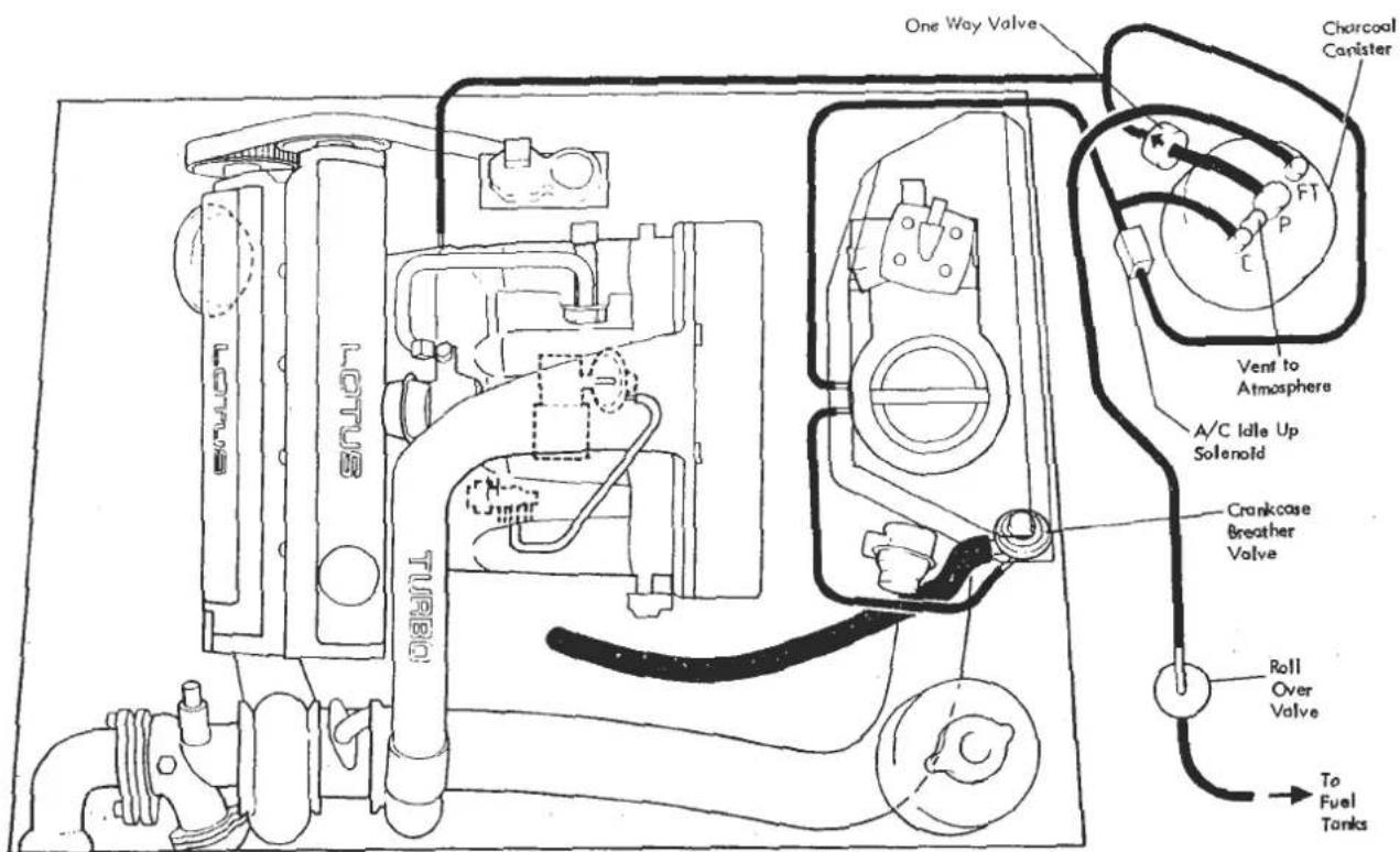
In addition, the small depression below the airflow sensor causes a lesser purge to take place through canister port 'C'.
At water temperatures above 70° C, with wide throttle openings and high rpm, when turbo boost pressure in developed, inlet manifold pressure becomes positive, and the manifold air rail hose is sealed by the one way valve, and A/C idle up solenoid (will not open above 1400 rpm). Purging now takes place through canister port 'C' to the depression (greater now with increased airflow) below the airflow sensor.
Crankcase Breather Valve.
Crankcase fumes are ventilated via the crankcase breather valve into the air cleaner housing. Positive crankcase pressure developed during normal running, is able to vent through the one way breather valve into the air cleaner housing.
In order to prevent these fumes, under low airflow engine idle conditions, escaping through the inlet trunking to atmosphere, the valve is also connected via a smaller bore hose, to the mild depression below the airflow sensor. This enables crankcase fumes at idle to pass directly into the intake tract and suppresses opening of the breather valve.
LD. 21 - ENGINE WARM UP SUMMARY
Engine Cranking
As soon as engine cranking takes place, the rpm relay switches on the fuel pumps and the system is pressurised to 6.5 bar main primary pressure. Air induced into the engine moves the airflow sensor which opens the fuel control valve and allows fuel to be delivered to the injectors. In addition, fuel is supplied by the cold start injector for a period controlled by the thermal time switch. Air by-passes the throttle butterflies via the auxiliary air valve and a/c idle up solenoid valve.
Cold Run - Below 35° C Oil Temp.
When the engine starts, the cold start injector closes, if it has not already done so, but air continues to flow via the auxiliary air valve, which closes as the engine warms. The ignition solenoid directs a vacuum pump supply to the throttle jacking capsule, and to the thermal ignition valve which itself directs the supply to the distributor advance capsule.
The control pressure set by the warm up regulator, is low, but increasing as the engine warms.
The frequency valve is set to run open loop @ 75% duty cycle rate.
Cold Run - Above 35°C Oil Temp., Below 53°C Water Temperature
As 35°C oil temperature is reached, the E.C.U. switches the frequency valve to run 'closed loop' (i.e. controlled by Lambda sensor @ around 50% duty cycle for L = 1).
Cold Run - Between 53° and 70° C Water Temp.
When 53°C water temp. is reached, the thermal ignition valve cuts off the vacuum pump supply to the D.A.C. and connects it with the throttle edge drilling.
Normal Running - Above 70°C Water Temp.
When 70°C water temp. is reached, the ignition solenoid cuts off the vacuum pump supply to the throttle jacking capsule.
The a/c idle up solenoid valve opens only at idle with the compressor operating.
LD 22 - FUEL SYSTEM PRECAUTIONS
Always ensure absolute cleanliness when working on any part of the fuel system. Thoroughly clean around any joint before disconnecting a component.
Pressure is maintained in the fuel system after the ignition is switched off by the action of the fuel accumulator, primary pressure regulator and control pressure shut-off valve. Therefore whenever disconnecting a fuel system joint, take care to use an absorbent cloth to protect from spray, and soak up the small amount of fuel released.
Take all necessary precautions to prevent sparks occurring whilst a fuel joint is disconnected.
Ensure that new sealing washers and gaskets are used on re-assembly, and that all joints are torque tightened in accordance with Section LD 25.
When fuel system tests are being performed involving the collection of fuel from fuel pumps, fuel injectors etc., the very strictest precautions must be taken to prevent sparks occurring in the vicinity of the working area. Any electrical switching necessary in the course of these tests should be performed by the ignition switch, or fuel pump inertia switches.
Ensure the working area is well ventilated
LD 23 ENGINE MANAGEMENT SYSTEM CHECK/SET UP PROCEDURE
Tools Required
i) Duty Cycle Meter T000T0567
ii) Continuity Meter T000T0568
iii) Exhaust Sample Probe T000T0501
iv) Stroboscopic Timing Light (proprietary)
- Connect the duty cycle meter to the frequency valve:
The frequency valve is located ahead of the fuel distributor. Disconnect the electrical plug from the valve and plug in the meter to both the valve, and the harness connector block as shown. Connect the crocodile clip to a good earth.
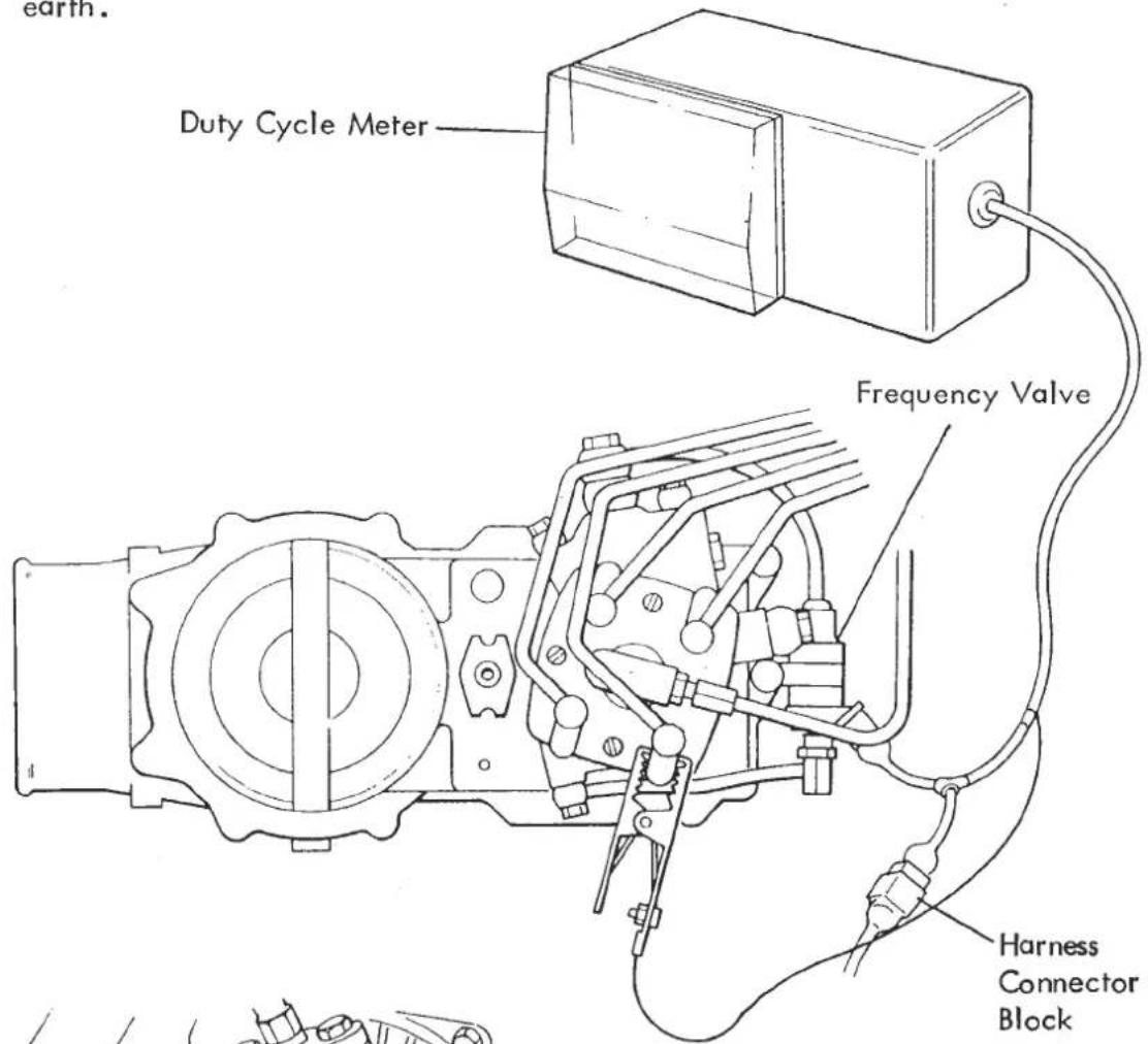

Connect the exhaust sample probe into the turbocharger adaptor and connect to a CO/HC analyser (e.g. Sun EPA 75 or equivalent).
Connect a stroboscopic timing lamp to No. 1 spark plug lead and remove grommet from clutch bell housing.
Start engine and run until normal operating temperature is reached (water temp. above 80°C).
- Check idle speed, 950 ± 50 rpm.
DO NOT ADJUST IDLE SPEED WITHOUT FIRST SLACKENING THROTTLE POSITION SWITCH MOUNTING SCREWS ON REAR OF No. 3/4 THROTTLE BODY.

If adjustment is required, first slacken the throttle position switch screws, and then adjust idle speed at the stop screw between throttle bodies 2 and 3.

Adjust throttle cable to suit if necessary.
After adjustment, connect continuity meter T000T0568 to the throttle position switch, and rotate switch until continuity is JUST made. Tighten screws and recheck setting.
- Check ignition timing at idle: 15° BTDC using the strobe and flywheel timing mark.
View of Clutch Housing Timing Aperture

Adjust, if necessary, at the distributor clamp. (Special Socket T000T0503)
- Check throttle jacking capsule adjustment:
Bridge connections to inlet manifold high temperature switch (use a spare fuse) to activate the capsule. Engine speed should hold at 1300 to 1500 rpm. Adjust if necessary at the clamp between capsule rod and throttle lever. Remove electrical bridge and re-check idle speed.
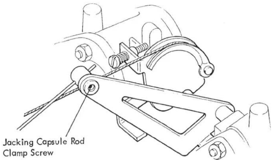
- Check duty cycle is between 45 - 55% with a 5 to 6% cyclic variation. The cyclic variation (flicking back and forth over a 5 to 6% range) indicates that the 'closed loop' feedback system is operating with the mixture strength constantly being amended by the frequency valve in conjunction with the Lambda sensor and E.C.U.
A steady reading indicates that an open loop circuit is operating (see Electronic Control Unit and wiring diagrams).
Check the CO level is 0.8% ± 0.5% and the HC level, as Hexane, is less than 500 ppm.
If the duty cycle or exhaust gas analysis are outside specification, remove the wiring grommet from the LH engine bay wall, and extract the Lambda sensor electrical connector. Disconnect the single spade connector to obtain an open loop exhaust gas reading. (Larger connector block is Lambda heating coil). If the mixture setting is correct disconnecting the Lambda sensor should have no effect on idle rpm.
Refer to the following table:
| Closed Loop Duty Cycle | CO Readings | Remark | See Section | |
| Closed Loop | Open Loop | |||
| 45 - 55% | O.K. | O.K. | System Satisfactory | |
| High | High | i) Sensor Faulty | ||
| ii) Injector Distribution | LD 24E 3 | |||
| iii) Throttle Imbalance | LD 24P | |||
| Over 55% | O.K. | Low | i) M.C.U. Setting too Lean | LD 24H |
| ii) Inlet System Air Leak | LD 24O | |||
| High | O.K. | i) Exhaust System Leaking | LD 24O | |
| ii) Sensor Faulty | ||||
| Under 45% | O.K. | High | M.C.U. Setting too Rich | LD 24H |
| Low | O.K. | Sensor Faulty | ||
LD 24 - FUEL INJECTION FAULT DIAGNOSIS
Note: When using this chart it is assumed that the general engine condition is satisfactory and ignition system is adjusted correctly. It is also assumed that the electrical system, including the safety cut-out circuit for the petrol injection system, has been checked and is in good working condition.
SYMPTOM

SYMPTOM Engine does not start in cold condition Engine does not start in warm condition Engine starts poorly in cold condition Engine starts poorly in warm condition (shakes) Irregular idling with warm-up phase (shakes) Irregular idling with warm engine manifold Engine backfires into intake manifold Engine backfires into exhaust system Engine misfires when operating on the road Driving performance unsatisfactory High petrol consumption CO level during idling too high CO level during idling too low Idle-speed cannot be adjusted (too high) POSSIBLE CA
POSSIBLE CAUSE
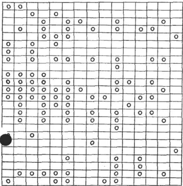
Electric fuel pump faulty
'Cold'control pressure outside specification
'Warm' control pressure too high
'Warm' control pressure too low
Auxiliary air valve does not close
Auxiliary air valve does not open
Cold start injector does not operate
Cold start injector leaking
Primary fuel pressure outside specification
Sensor plate rest position incorrect
Sensor plate and/or control plunger sticking
Vacuum system leaking
Overall fuel system leaking
Fuel injector(s) leaking or opening pressure low
Basic mixture adjustment too rich
Basic mixture adjustment too lean
Throttle does not open/close completely
Thermo time switch does not close
Fuel by-pass valve
Throttle jacking capsule
Throttle position switch
Air leaks in exhaust/inlet
Throttle imbalance
E.C.U. faulty. See electrical LD 26/27/28
A - FUEL PUMPS
- Check inertia switch and fuel pump fuses. (LD 26).
-
Remove fuel pump control relays and fit electrical test bridges T000T0569. The fuel pumps should be heard running. If no sound is heard, refer to LD 26/27/28 for electrical diagnosis.
-
With pumps running, check voltage drop at terminals of both pumps. Minimum = Engine Running: 11.5 V, Engine Stopped: 10.0 V. Remove test bridges from pump control relay bases. To check that sufficient fuel is supplied to the injection system:
Tools required:
Test Hose
T000T0579
Graduated Flask
T000T0582
Electrical Test Bridges
T000T0569
- Check Fuel Return Quantity from Distributor Fit the test hose T000T0579 to the fuel distributor return connection (see Fuel System Precautions LD 22) and place into graduated flask

Trip inertia switch and fit electrical test bridges T000T0569 to fuel pump control relay bases.
Press down inertia switch for a short time to prime the system. Empty flask.
Press down inertia switch for exactly 30 seconds and measure quantity of fuel delivered.
Specification: 1250 ± 100cc
If the quantity is insufficient:
- Check Fuel Delivery Quantity at Secondary Pump Outlet:
Fit the test hose to the secondary fuel pump outlet connection, and place end in graduated flask.
![graph LR A["FUEL PUMPS"] --> B["FUEL FILTER"] B --> C["FUEL ACCUMULATOR"] C --> D["FUEL TANK"] E["Secondary Pump Outlet Connection"] --> C](/content/2026/05/1021120/images/0eccc3b60a1da9546e9083139ed341f944cf42fa14d84ab9997563bb4c47f0fc.jpg)
Trip inertia switch and fit electrical test bridges to fuel pump control relay bases. Press down inertia switch for exactly 30 seconds, and measure fuel quantity delivered.
Specification: 1850 ± 100cc
If delivery is OK, replace the fuel filter.
If below specification:
- Check Fuel Delivery Quantity at primary Pump Outlet
Fit the test hose to the primary pump outlet connection, and place end in graduated flask.
![graph LR A["FUEL PUMPS"] --> B["FUEL FILTER"] B --> C["FUEL ACCUMULATOR"] C --> D["FUEL TANK"] E["Primary Pump Outlet Connection"] --> A](/content/2026/05/1021120/images/64b9117c736e5e803eae650a1a0067fc21a1112cea5fca2ea705138d3c5d61a4.jpg)
With electrical test bridges fitted, press down inertia switch for exactly 30 seconds and measure fuel quantity delivered.
Specification: 1800 ± 100cc
If delivery is below specification, disconnect supply pipe from pump and provide with alternative known supply. Repeat test.
If delivery is now OK, clean, repair or replace tank. If delivery insufficient replace primary fuel pump.
B - FUEL PRESSURES
Tools required:
Test Gauge T000T0575
Electrical Test Bridges T000T0569
1. Check Primary Pressure
Trip inertia switch, remove fuel pump control relays and fit electrical test bridges into relay bases.
Fit test gauge to fuel distributor inlet connection with gauge valve toward distributor. (see Fuel System Precautions LD.22)
Ensure gauge valve is OPEN

Press down inertia switch and record primary fuel pressure from gauge. Trip inertia switch.
Specification: 6.0 - 6.8 Bar @ 20°C
If pressure is below specification:
2. Check Supply Pressure to Fuel Distributor
i) Check gauge valve is fully open.
ii) Press down inertia switch and gradually close gauge valve very slowly until pressure rises to 10.0 Bar, DO NOT close gauge valve further as pressures in excess of 10 Bar are liable to cause damage to the system and/or gauge.
iii) Trip Inertia switch
Specification: At least 10.0 Bar
If pressure is below specification, check quantity of fuel delivered at secondary fuel pump outlet (see LD 24 A5).
If supply pressure to distributor is OK, but primary pressure too low:
3. Adjust Primary Pressure Regulator
Remove the pressure regulator from the fuel distributor by unscrewing the hexagonal nut shown (see Fuel System Precautions LD. 22).
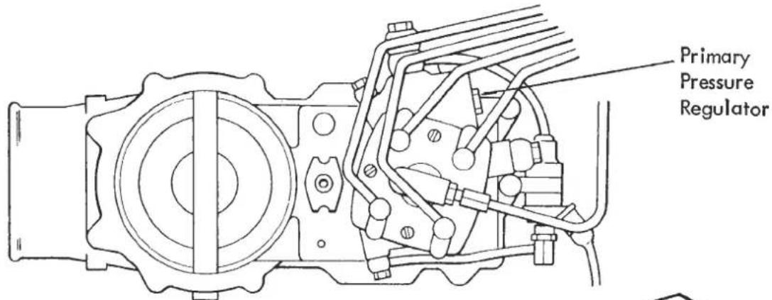
NOTE
THIS ITEM SHOULD NEVER
REQUIRE ATTENTION UNDER
NORMAL CIRCUMSTANCES

Adjusting Shims
Adjust the shim pack as necessary to correct primary pressure - adding 0.1mm shim thickness increases pressure by about 0.15 bar.
Renew 'O' ring and replace regulator into distributor.
Re-test primary pressure.
4. Check Cold Control Pressure
Carry out this test ONLY at an ambient temperature of 30° C or lower.
Fit the test gauge to the warm up regulator as shown.
(See Fuel System Precautions LD.22).
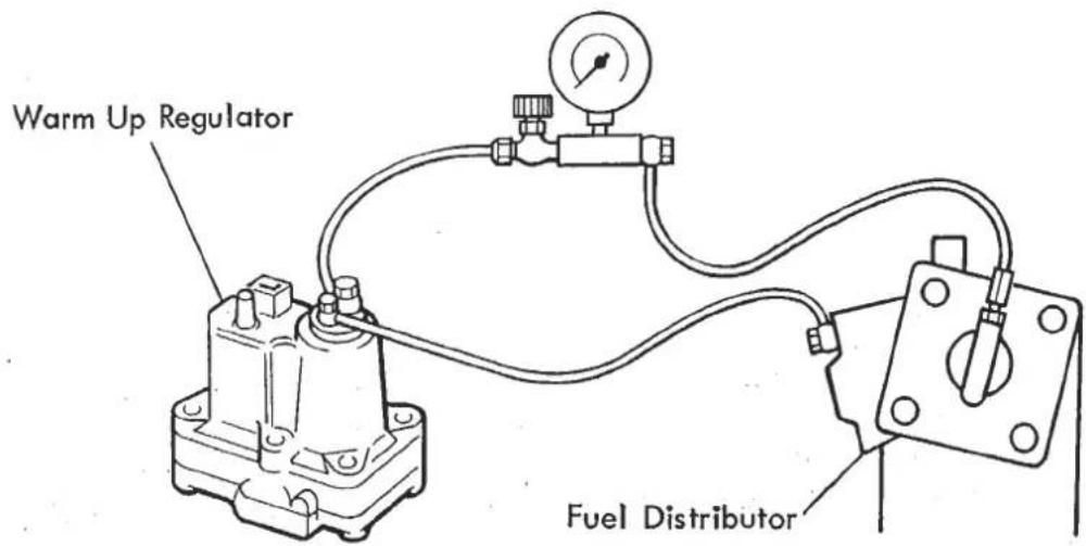
Open gauge valve.
With test bridge fitted, see (1), press down inertia switch and record cold control pressure from gauge. Trip inertia switch.
Compare the reading obtained with the graph shown.
"Cold" Control Pressure
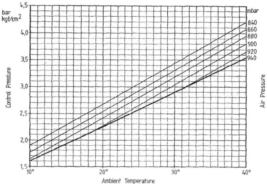
The basic curve applies for an air pressure of 947 mbar and higher (corresponding to see level up to an altitude of about 600 m above see level).
Permissible tolerance of the basic curve: + 0.2 bar.
If the site where the measurements are made is located at higher altitudes, it is essential that the exact air pressure in known on the day when the measurements are made in order to determine the correct control pressure. (Use an accurate barometer, or ask the weather bureau or an airport if one or the other is near and at the same altitude).
Tolerance of the control-pressure altitude curves: + 0.25 bar.
If the "cold" control pressure differs from the nominal value, replace the warm-up regulator.
5. Check Warm Control Pressure
With the test gauge fitted as in (4), (gauge valve open) remove the electrical test bridges, refit fuel pump control relays, and press down inertia switch. Start engine and observe gradual rise in control pressure. When the warm up regulator bimetal strip is fully heated the pressure will stabilise. Record reading and switch off.

The nominal control pressure should be read from the curve in accordance with the air pressure.
The effect of the altitude compensation begins at an air pressure of about 933 mbar, i.e. starting at about 600 m. At higher altitudes it is essential that the exact air pressure is known on the day when the measurements are made. (Use an accurate barometer, or ask the weather bureau or an airport if one or the other is near and at the same altitude).


If the control pressure does not rise from the cold setting, check the feed and earth connections at the warm up regulator.
If warm control pressure is outside specification, replace warm-up regulator.

6. Check for Fuel System Leaks, Internal & External
With the fuel pumps running, carry out a thorough visual inspection of all fuel system connections.
With the test gauge fitted as in (4) and with the gauge valve open, start engine and switch off when 'warm' control pressure is reached. Observe and record the drop in pressure with time.
Specification: Minimum 3.0 Bar after 30 mins.
If the pressure drops too quickly, repeat the test, closing the gauge valve as the engine is switched off, thus isolating the control pressure circuit.
If the same result is found, the leak is in the primary pressure circuit. If however, the second result is within specification, the leak is in the control pressure circuit.

Possible causes of primary pressure leak:
i) Non return valve in secondary fuel pump. Replace pump.
ii) Leak from cold start valve or fuel injector. (see Section D & G).
iii) 'O' ring in primary pressure regulator leaking. Replace 'O' ring.
iv) Fuel accumulator leaking past diaphragm. Replace.
Fit the pressure gauge at the fuel distributor inlet connection, and at the secondary fuel pump outlet connection (see Section 'A') and record rate of pressure drop to establish faulty component.
Possible causes of control pressure leak:
i) Control pressure shut off valve leaking. Replace.
Use new sealing washers whenever re-making a fuel system connection, and refer to fuel system torque settings Section LD 25.
C - AUXILIARY AIR VALVE
Cold Test
If the engine is not cold, the valve may be removed and cooled by freezer.
Remove both hoses from the unit, and with the aid of a mirror and lamp, observe the position of the valve plate, which should be partially open, dependent on temperature. If the valve is completely closed, replace the auxiliary air valve.
Quick Test: Clamping off an air valve hose on a cold engine should reduce idle rpm.

Hot Test
Disconnect RPM relay and bridge connector block terminals 30 and 87.
After a maximum of 5 minutes the auxiliary air valve must be completely closed aided if necessary by tapping the valve assembly with a soft faced mallet to compensate for lack of engine vibration.
If the valve does not close completely, check the electrical feed to the valve and resistance of the valve heating coil for open circuit. Replace if defective.
Quick Test: Clamping off an air valve hose on a warm engine should have no effect on idle rpm.
D - COLD START INJECTOR
Disconnect the cold stert injector electrical plug and release injector, with pipe attached, from inlet maniflod. Taking care not to kink the fuel pipe, place the injector in a glass jar, or graduate, and fit electrical test lead T000T0570. Connect test leads to ignition coil terminals. Switch on ignition and press test lead button. Fuel should spray from the injector. If no spray, check electrical feed and, if necessary, renew cold start injector.
If spray is OK, switch off ignition and wipe injector nozzle clean. Remove electrical test lead and refit cold start injector plug. Switch on ignition and observe valve for one minute, during which time no fuel should be seen to seep from the valve. Refit injector to manifold.
E - SENSOR PLATE
-
Remove the air cleaner body for access to the sensor plate. Check that the sensor plate is concentric with and can move freely through the narrowest part of the air funnel.
Re-position if necessary after loosening the plate fastening screw, and re-tighten to 0.51 - 0.56 kgf.m (3.7 - 4.1 lbf. ft.). -
Remove fuel pump control relays, and fit electrical test bridges T000T0569 into relay bases for about 10 seconds to run the fuel pumps and apply control pressure to the fuel control valve in the fuel distributor. Remove test bridges.
Check the rest position of the sensor plate.

The upper edge of the sensor plate must be flush with the top edge of the funnel's narrowest section, as shown. A position up to a maximum of 0.5 mm higher is permissible, but the lower edge of the sensor plate must not project at any point on its circumference above the funnel narrow section.
NOTE:
The lower edge of the sensor plate is chamfered. Ensure the plate is fitted the correct way up, with the word 'TOP' uppermost and the chamfered edge on the underside.
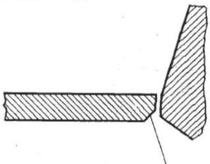
Chamfered edge on bottom
If the sensor plate rest position is too high, the stop pin for the rest position spring may be adjusted by the careful use of a pin punch and light hammer. CAUTION: Take care not to over adjust, as the mixture control unit must then be removed for the pin to be knocked back. Repeated adjustments will loosen press fit.
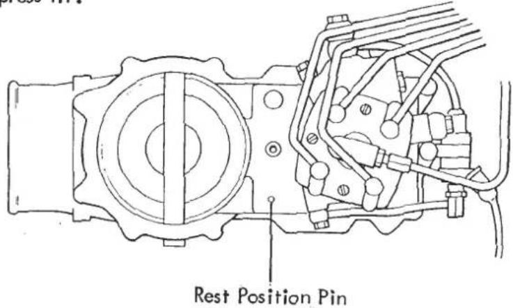
If adjustment has to be made, also check ignition system as the likely cause of sensor plate mal-adjustment is backfire down inlet system.
- Check the free movement of the airflow sensor and fuel distributor control valve, and comparative fuel delivery between injectors. Remove each injector from maniflod (leave pipe attached) and place in graduated flask T000T0594J. Trip inertia switch. Remove fuel pump control relays and fit electrical test bridges T000T0569 into relay bases. Depress inertia switch.
a) Press down the airflow sensor. The same resistance must be felt over the entire movement. Move the sensor plate rapidly back to a position just in front of the zero stop. The control plunger follows this rapid movement of the sensor plate only sluggishly, and therefore initially loses contact with the sensor plate lever. It must be possible, however, to feel the plunger make contact with this lever again. If this condition is fulfilled, the control plunger can be considered to move freely.
b) Check that the control lever moves freely; press the sensor plate to its full deflection again, and then release it. The sensor plate should snap back to the zero position and bounce up about twice from the spring-loaded stop.
c) Trip inertia switch and remove test bridges. Compare quantity of fuel delivered from each injector. Maximum permissible difference between any two injectors: 7.0% If this tolerance is exceeded, interchange injectors and/or injector feed pipes, and repeat test to establish whether fault lies with injector, feed pipe, or fuel distributor. Replace parts as necessary.
If the sensor control lever is found not to move freely, free pivot as necessary, or replace airflow sensor. If the control plunger does not move freely, remove fuel distributor for access to plunger:
See Fuel System Precautions LD. 22
i) Use a cloth to absorb the small amount of pressurised fuel released when the warm up regulator feed pipe is gradually slackened from the distributor. Release all other fuel pipe connections to the fuel distributor taking all precautions necessary to minimise fire hazard.
ii) Release the three screws securing the distributor to the air flow sensor body and remove distributor taking care that the control valve does not drop out.
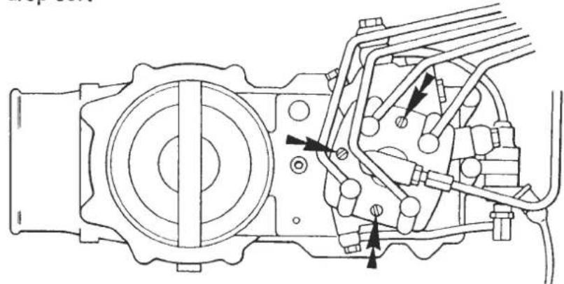
Distributor Fixing Screws
iii) Remove the plunger - under certain conditions, in order to do this it may be necessary to blow compressed air against the plunger through the control-pressure connection hole. Hold the plunger with your hand while doing this.

Clean the plunger thoroughly with petrol. If the plunger still does not move freely, replace the fuel distributor.
iv) Refit the fuel distributor using a new sealing ring between distributor and airflow sensor body. Tighten the three fixing screws to 0.32 - 0.38 kgf.m (2.3 - 2.7 lbf. ft.). Refit fuel pipes to distributor using new sealing washers and tightening M8 bolts to 8.3 kgf. m (7 lbf. ft.), M10 bolts to 2.0 kgf.m (15 lbf. ft.).
v) Carry out the mixture setting up procedure described in LD 23 - H.
F - VACUUM SUPPLY
Use the vacuum switching diagram and a 0.30 in. Hg vacuum gauge to measure the vacuum available at the ignition solenoid, throttle jacking capsule, thermal ignition valve, and distributor advance capsule under the different engine coolant temperatures. A minimum of 18 in. Hg should be recorded at any point in the vacuum line switched to the vacuum pump (with engine running).
If a lesser figure is obtained, check at the vacuum pump. If pump performance is below specification, check vac. pump exhaust pipe for restriction, and 'V' belt drive for fault.
Replace pump if necessary.
With satisfactory vacuum pump performance, clamp off, or disconnect individual components to isolate leaks and replace pipes or components as necessary. Check secure fit of all vacuum pipes.

VACUUM SWITCHING DIAGRAM - BELOW 53° C WATER TEMP.

VACUUM SWITCHING DIAGRAM - BETWEEN 53° - 70° C WATER TEMP.

VACUUM SWITCHING DIAGRAM - ABOVE 70° C WATER TEMP.
G - FUEL INJECTORS
-
Remove the injectors from the inlet manifold (see Fuel System Precautions LD 22) and test individually using tool T000T0580 and white spirit.
-
Connect an injection valve to the valve tester and bleed the discharge tubing by moving the lever back and forth several times with the union nut open. Then tighten the union nut.
-
Check for dirt.
Move the hand lever slowly (about 2 seconds per stroke) back and forth with the stopcock on the pressure gauge open. If the pressure does not build up to 1 - 1.5 bar, the injection valve has a leak, caused possibly by dirt in the valve.
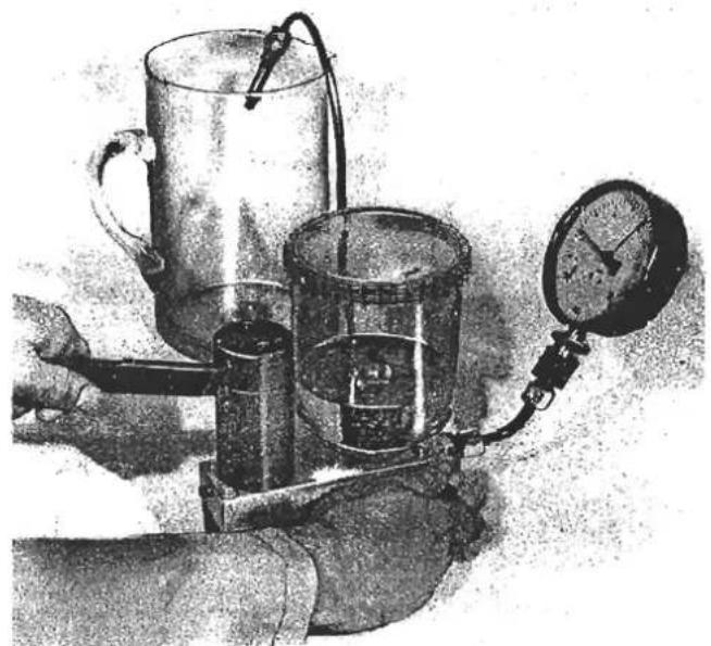
Attempt to flush the injection valve clear by moving the lever back and forth several times vigorously.
If this attempt is successful, continue the test. If it is not possible to flush the valve clear, replace it.
- Test the opening pressure.
With the stopcock closed, flush the valve out and bleed it with several rapid movements of the lever.

Open the stopcock and test the opening pressure by moving the lever slowly (about 2 seconds per stroke).
Injector opening pressure: 3.5 ± 0.6 Bar If the opening pressure is outside.tolerance, replace the injection valve. Individual valves can be changed within a set.
- Leakage test.
Open the stopcock, build the pressure up slowly to a value 0.5 Bar under the opening pressure determined previously and hold it constant at that level. The injector must not drip for at least 15 seconds.
- Chatter test, evaluation of spray.
Move the lever back and forth at about 1 stroke per second. As this is done, the valve must chatter. No drops of fuel must form at the mouth of the valve. The valve must not produce a "cord spray". Formation of a single-sided atomized spray within an overall spray angle of about 35° is permissible (see example given in illustrations).

Good spray formation.
Single-sided but nevertheless good spray formation.

Poor spray formation; replace injection valves.

Drop formation
"Cord" spray

"Spray in strands"
7. Refitting fuel injectors:
Ensure 'O' rings are undamaged. Lubricate the manifold injector hole with a silicone spray and carefully slide the injector down the hole pressing it away from the air rail cross-drilling hole.
Push the larger 'O' ring into its recess using a tube of suitable diameter so that pressure is applied directly to the 'O' ring.
Fit and tighten the injector retaining clamp.
Torque tighten fuel pipe connection to 2.0 kgf.m (15 lbf.ft.).
H - BASIC MIXTURE ADJUSTMENT
Refer to section LD 23 to establish whether the basic mixture setting requires adjustment, or some other component is the cause of an out of specification duty cycle reading.
If adjustment is required:

Remove the anti-tamper plug from the mixture control unit, and use a 3 mm allen key to turn the airflow sensor lever adjusting screw clockwise to reduce the duty cycle rate, or counterclockwise to increase the duty cycle meter reading. Turn only a small amount at a time, and blank off the access hole (with finger) between adjustments. 'Blip' the throttle and re-check duty cycle reading.
When adjustment is completed, refit the anti tamper plug to the access hole. Repeat LD 23 checking procedure.
If a new mixture control unit, or component thereof, is fitted to the engine, or if, for whatever other reason the setting of the basic mixture adjustment screw is unknown or in doubt, it is essential to carry out the following procedure to prevent the possibility of the engine hydraulic locking and causing extensive internal damage.
Disconnect one injector pipe and fit a slave injector, placing into a glass jar or graduate. Trip inertia switch. Remove fuel pump control relays and fit electrical test bridges T000T0569 into relay bases.
Remove anti-tamper plug from mixture adjustment screw access hole.
Press down inertia switch and briefly press down airflow sensor to prime fuel injector.
Using a 3mm allen key, turn the mixture adjustment screw, without pressing down the airflow sensor, until fuel can just be seen to drip from the injector. Turn the screw 1/2 turn counterclockwise. Trip inertia switch and remove electrical test bridges. Refit fuel pump control relays, and reset inertia switch. Remove slave injector and re-connect injector pipe.
Temporarily blank off mixture screw access hole whilst following LD 23 procedure to check duty cycle rate, and adjust if necessary as above.
I - THROTTLE DOES NOT OPEN COMPLETELY
Check that with the accelerator pedal pressed to its fullest extent, the full throttle stop bracket on the butterfly spindle is in contact with the throttle body abutment. Adjust throttle pedal downstop as necessary.
J - THERMO-TIME SWITCH
To test the switch, remove from the manifold and plug the hole to prevent coolant loss. The switching temperature and time period at - 20°C are stamped on one of the switch hexagon flats.
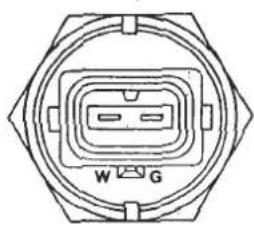

| Design | At a temperature | Resistance measurement in ohms between | |||
| under °C | over °C | Therm 'G' and 'Ground' (Housing) | Term 'W' and 'Ground' | Term 'G' and term 'W' | |
| 38°C/8s | +30 | 25...40 | 0 | 25...40 | |
| +40 | 50...80 | 100...160 | 50...80 | ||
Measure the resistance between the connection listed in the table after standing the switch in water at the appropriate temperature for 10 minutes. Replace switch if necessary.
L - FUEL BY-PASS VALVE
With the engine at normal running temperature, remove the valve from the air filter box, and observe the valve action on closed throttle engine overrun conditions. If the valve does not open, check electrical feed and refer to electrical sections LD. 26/27/28.
Check the closed valve position by blowing down the pipe.
M - THROTTLE JACKING CAPSULE
With engine idling at normal operating temperature, check first that idle speed is correct @ 950 ± 50 rpm. Do not adjust without first referring to Section LD 23.

Capsule Rod Clamp Screw
Bridge connections to high temperature switch in inlet manifold (use a spare fuse) to activate the capsule. Engine speed should hold at 1300 to 1500 rpm. Adjust if necessary at the clamp between capsule rod and throttle lever. Remove electrical bridge and re-check idle speed.
N - THROTTLE POSITION SWITCH
Connect continuity meter T000T0568 to the throttle position switch. With the throttles shut the meter should indicate continuity by buzzing, which should stop at the smallest throttle opening. At about 30° of throttle angle, continuity should again be made.
IT IS ESSENTIAL TO SLACKEN THE THROTTLE POSITION SWITCH MOUNTING SCREWS BEFORE ADJUSTING ENGINE IDLE SPEED. IMBALANCE OF THE THROTTLE BUTTERFLIES MAY OTHERWISE OCCUR.

If the throttle position switch requires adjustment, check first that the warm idle speed is correct. Slacken the throttle position switch mounting screws before making any idle speed adjustment. When completed, rotate the position switch slowly until continuity is JUST made, and tighten screws. Recheck setting.
O - AIR LEAKS IN EXHAUST/INLET
To check for air leaks in the exhaust and inlet system:
Disconnect the turbo to diffuser hose, and apply an airline with a suitable sealing adaptor into the diffuser. Seal the exhaust tailpipe with a bung.
Paint all inlet/exhaust system joints and seals with a soap & water solution and check for leaks whilst applying an air pressure of 5 lb/in 2 into the diffuser.
P - THROTTLE IMBALANCE
If throttle imbalance is diagnosed in procedure LD23, check the throttle position switch switch adjustment (LD24N).
CAUTION The throttle bodies and inlet manifold assembly are balanced as a car set by mass flow, and the throttle bleed channels permanently sealed at the factory. Although provision is made for measuring the inlet manifold depression on cylinders 2 & 3 and adjusting the throttle spindle coupling, this setting should not be disturbed unless essential.
Throttle imbalance can only be caused by abuse of the throttle spindle assembly, or replacement of a throttle lever or return spring.
Investigate all other potential causes of incorrect CO levels before proceeding.
Tools required:
Special Diffuser
T000T0583
Coupling Spanner
T000T0584
Manometer
T000T0499
Balance Tubes
T000T0496 (2)
Remove the blanking plugs from inlet tracts 2 and 3 and fit the balance tubes T000T0496. Connect to manometer. Remove diffuser, and fit special diffuser T000T0583 in its place.

With engine idling at normal running temperature examine the depression in tracts 2 and 3. Use spanner T000T0584 to slacken the coupling locknut and adjust coupling screw, to obtain optimum balance between mercury columns. Re-tighten locknut and re-check balance.
Remove special tools, and return to procedure LD23. If throttle imbalance is still indicated as the cause of high CO readings, the throttle bodies and manifold assembly must be replaced as a set, mass flowed at the factory.
LD 25 - TORQUE SETTINGS - FUEL SYSTEM
| Fuel Distributor | 8 x 1 | 9 Nm | 0.9 kgf.m | 7 lbf.ft. |
| 12 x 1.5 | 20 Nm | 2.0 kgf.m | 15 lbf.ft. | |
| Fuel Injectors | 20 Nm | 2.0 kgf.m | 15 lbf.ft. | |
| Cold Start Injector | 9 Nm | 0.9 kgf.m | 7 lbf.ft. | |
| Warm Up Regulator | 8 x 1 | 9 Nm | 0.9 kgf.m | 7 lbf.ft. |
| 10 x 1 | 14 Nm | 1.4 kgf.m | 10 lbf.ft. | |
| Frequency Valve | 12 Nm | 1.2 kgf.m | 9 lbf.ft. | |
| Fuel Pump | 22 Nm | 2.2 kgf.m | 16 lbf.ft. | |
| Fuel Accumulator | 25 Nm | 2.6 kgf.m | 18 lbf.ft. | |
| Fuel Filter - in | 26 Nm | 2.7 kgf.m | 19 lbf.ft. | |
| - out | 35 Nm | 3.6 kgf.m | 26 lbf.ft. | |
| Fuel Tank (in & out) | 22 Nm | 2.2 kgf.m | 16 lbf.ft. |
REPLACE SEALING WASHERS EVERY TIME A JOINT IS BROKEN


LD.26.-IGNITION BOX COMPONENT LOCATION DIAGRAM
Page 52
SECTION LD
LD 27 - WIRING DIAGRAM SCHEMATICS - FUEL INJECTION
Circuit Descriptions
- Base Circuit. Ignition Off. Cold Engine (Below 35°C)
A positive feed is provided to the RPM relay.
- Cold Crank. Below 35°C Oil Temp.
When the ignition is switched on, the Lambda sensor heating coil is operated, and the fuel by-pass control relay activated via the throttle position switch earth circuit. An ignition feed is also provided to terminal 15 of the rpm relay.
When the engine is cranked, a negative signal from the ignition coil activates the electronic control in the RPM relay allowing the ignition feed to operate the relay coil, and earth via terminal 31. The relay contacts now connect the positive feed from terminal 30 to the fuel pumps via terminal 87b, and to the injection control circuit via terminal 87.
The injection control circuit supplies a positive feed to terminal 8 of the E.C.U., the frequency valve and the heating coils of the auxiliary air valve and warm up regulator.
The closed high temp. switch supplies the fast warm up relay. See circuit (3). A feed from the cold start contact on the starter motor solenoid supplies the cold start injector which is controlled by the thermal time switch.
Earth signals are supplied to terminals 12 and 6 of the E.C.U. via the low temp. switch and fuel by-pass control relay (via idle changeover relay).
- Cold Run & Idle. Below 35° C Oil Temp.
Similar to circuit (2) except:
The cranking circuit feed to the thermal time switch and cold start injector is switched off.
The fast warm up relay, activated by the closed high temperature switch, provides an earth circuit for the ignition solenoid which receives a feed from the ignition auxiliary circuit. The ignition solenoid operates the throttle jacking capsule which, at idle, prevents the throttle position switch 'closed' contact closing. No earth signal is supplied to E.C.U. terminal 6.
- Cold Run & Idle. Above 35° C Oil Temp. Below 70° C Water Temp.
Similar to circuit (3) except:
Low temp. switch opens and cuts off earth signal to E.C.U. terminal 12. Lambda sensor operational.
- Normal Idle. Above 70°C Water Temp.
Similar to circuit (4) except:
High temp. switch opens and de-energises the fast warm up relay. This relay now provides an earth (via the idle up relay) for the idle up solenoid which is energised and closes.
The ignition solenoid is de-energised, which de-activates the throttle jacking capsule (vacuum operated) allowing the throttle position switch to close. The throttle position switch energises the fuel by-pass control relay, which provides an earth signal (via idle changeover relay) to E.C.U. terminal 6.
- Normal Run, Above 1600 rpm. Above 70°C Water Temp. Below 30° Throttle Angle
Similar to circuit (5) except:
Throttle position switch is open. No earth signal to E.C.U. terminal 6. Negative feed from ignition coil activates speed sensing module in fuel by-pass speed sensing relay and allows ignition feed from terminal 15 to energise the relay and earth via terminal 31 and the fast warm up relay. Terminal 88a of the fuel by-pass speed sensing relay, supplies a 12 volt positive to the idle up control relay, which prevents the a/c idle up solenoid opening, and to the idle changeover relay.
- Normal Run. Above 70°C Water Temp. Over 30° Throttle Angle.
Similar to circuit (6) except:
Throttle position switch supplies earth signal to E.C.U. terminal 7.
- Overun. Above 1400 RPM. Decelerating from over 1600 RPM
Similar to circuit (6) except:
Throttle position switch is closed energising the fuel by pass-control relay. This provides an earth signal via the idle changeover relay to E.C.U. terminal 7.
The energised fuel by-pass control relay also provides an earth circuit for the fuel by-pass valve and 'ECON' lamp.
Below 1400 rpm, the fuel by-pass speed sensing relay drops out, and circuit (5) applies.
- Air Conditioning Compressor Operating. At Idle, Above 70°C Water Temp.
Similar to circuit (5) except:
A feed from the compressor circuit is directed via the idle up control relay to energise the idle up relay. This cuts off the earth circuit for the a/c idle up solenoid, which is de-energised and opened.
This circuit only operates below 1400 rpm.
- Light Throttle. Over 3250 RPM
Similar to circuit (6) except:
The fuel enrichment module, supplied with a negative feed from the ignition coil, senses when an engine speed of 3250 rpm is reached, and allows an ignition feed to operate the relay coil and close the relay contacts. This provides an earth signal to E.C.U. terminal 7.

- BASE CIRCUIT. IGNITION OFF. COLD ENGINE (BELOW 35°C)


SECTION 1D
Page 56
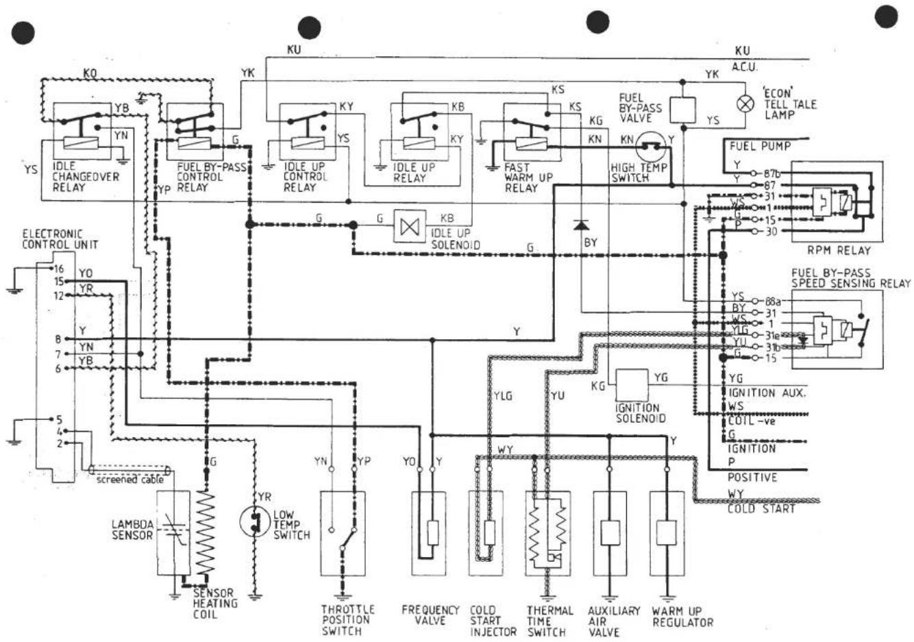
- COLD CRANK. BELOW 35°C OIL TEMP.
SECTION LD
Page 57
![graph TD subgraph Control Unit A["16 YO"] --> B["LAMBDA SENSOR"] C["15 YR"] --> D["SENSOR HEATING COIL"] E["12 Y"] --> F["YN"] G["8 Y"] --> H["YB"] I["7 Y"] --> J["6"] K["5"] --> L["screened cable"] M["2"] --> N["G"] O["16 YO"] --> P["G"] Q["15 YR"] --> R["G"] S["12 Y"] --> T["G"] U["8 Y"] --> V["G"…](/content/2026/05/1021120/images/b06aa4ceeaf6aa4eb577d71fbdc0e01007288d4e0c40d9c8e3efb33d211cb623.jpg)
- COLD RUN & IDLE. BELOW 35°C OIL TEMP.
Page 58
SECTION LD


- COLD RUN & IDLE. ABOVE 35°C OIL TEMP. BELOW 70°C WATER TEMP.
SECTION LD
![graph TD A["LELE CHANGEOVER RELAY"] --> B["FUEL BY-PASS CONTROL RELAY"] B --> C["IDLE UP CONTROL RELAY"] C --> D["IDLE UP RELAY"] D --> E["FAST WARM UP RELAY"] E --> F["FUEL BY-PASS VALVE"] F --> G["YS"] G --> H["ACU."] H --> I["ECON' TELL TALE LAMP"] I --> J["FUEL PUMP"] J --> K["RPM RELAY"] K -->…](/content/2026/05/1021120/images/5f6620778529e689f28737905d198a29e2d56f9a8f3dfbe1fefedbf6dd30b94a.jpg)
Page 60
SECTION ID
- NORMAL IDLE. ABOVE 70°C WATER TEMP.


![graph TD A["EDLECTRONIC CONTROL UNIT"] --> B["screened cable"] B --> C["LAMBDA SENSOR"] C --> D["SENSOR HEATING COIL"] D --> E["YR LOW TEMP SWITCH"] E --> F["THROTTLE POSITION SWITCH"] F --> G["FREQUENCY VALVE"] G --> H["COLD START INJECTOR"] H --> I["THERMAL TIME SWITCH"] I --> J["AUXILIARY AIR VAL…](/content/2026/05/1021120/images/c8aaef6c666daea0f309b188baa6051225b63746920182f918dc2b409013ac90.jpg)
- OVERUN. ABOVE 1400 rpm DECELERATING FROM ABOVE 1600 rpm
SECTION LD
Page 63
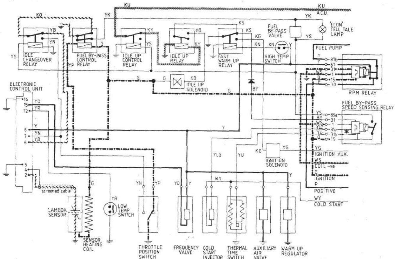
- AIR CONDITIONING COMPRESSOR OPERATING. AT IDLE. ABOVE 70°C WATER TEMP.


Page 64
SECTION LD


LD. 28 - ELECTRICAL COMPONENT FUNCTION & FAULT DIAGNOSIS
1. Idle Change Over Relay
Location: Coil box
Mating connector colour: Black
Change over relay controlled by fuel by-pass speed sensing relay, energised when R.P.M. has exceeded 1600 R.P.M. and de-energised below 1400 R.P.M.
Switches pin 7 of electronic control unit to ground, when fuel by-pass control relay is energised, on deceleration until 1400 R.P.M. when it changes over to switch pin 6 of electronic control unit to ground

Normally open change over relay

Terminals 85 and 86 relay windings
Terminals 30/51, 87A and 87 switching contacts
Lotus Part A079M6141F (Silver)
2) Fuel By-Pass Control Relay
Location: Coil box
Mating connector colour: Blue
Double contact relay controlled by ignition (fuse 23 in fusebox) and throttle position switch. Energised when throttle is in the closed position.
Switches idle change over relay and fuel by-pass valve to ground when ignition is on and throttles are in the closed position.

Terminals 85 and 86 relay windings
Terminals 30, 87 and 87b switching contacts

Lotus Part A082M6182 (Grey)
- Idle Up Relay
Location: Coil box
Mating connector colour: Black
Change over relay (schimatic as shown item one). Controlled by idle up control relay. De-energises idle up solenoid, when air condition compressor is operating, below 1400 R.P.M.
- Fast Warm Up Relay
Location: Coil box
Mating connector colour: Black
Changeover relay (schimatic as shown item one). Controlled by high temperature switch energises ignition solenoid when the high temprature switch is closed circuit. Energises idle up solenoid and fuel by-pass speed sensing relay when the high temperature switch is open circuit.
- Idle Up Control Relay
Location: Coil box
Mating connector colour: Black
Changeover relay (schimatic as shown in item one). Controlled by fuel by-pass speed sensing relay.
Energised when R.P.M. has exceeded 1600 and de-energised below 1400 R.P.M. Switches out idle up relay above 1600 R.P.M.
- Fuel By-Pass Speed Sensing Relay
Location: Coil box
Mating connector colour: Black. Additional information see LD 16.

Controlled by low tension ignition pulses to give engine speed sensing, also thermally inhibited operation by fast warm up relay.
Energises fuel by-pass valve and econ tell-tale on deceleration from an engine R.P.M. of greater than 1600 until 1400 R.P.M. when the throttles are closed. This unit also supplies a 12 volt positive to the idle changeover relay and idle up control relay supply when engine R.P.M. has exceeded 1600 and maintains that supply until engine R.P.M. has dropped to 1400.
- Fuel By-Pass Valve
Location: Rear of induction air box
Mating connector colour: Black. Additional information see LD 16.
Electrically controlled vacuum/air valve, controlled by the fuel by-pass speed sensing relay in conjunction with the fuel by-pass control relay.
- "Econ" Tell-Tale Lamp
Location: Right hand bank of tell tale lamps on instrument binnacle.
Tell-tale lamp to indicate to the driver when the fuel by-pass valve is operating.
9. High Temperature Switch
Location: Water rail, inlet manifold. Additional information see LD 18. Controls fast warm up relay. Sensing coolant temperature goes open circuit on raising temperature at 70° C and closed circuit on falling temperature at 60° C.
10. Idle Up Solenoid
Location: Right hand fuel tank board. Additional information see LD 19. Electrically operated air valve. Air way open when valve is electrically de-energised. Controlled electrically by the idle up relay and fast warm up relay.

11. R.P.M. Relay
Location: Coil box
Mating connector colour: Blue
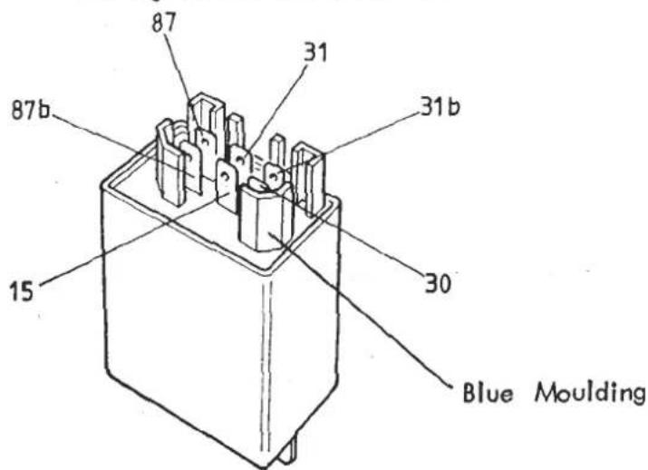
Senses ignition pulses in the low tension circuit and requires a minimum of 4 R.P.M. before making contact and thereby energising the fuel pump and injection circuits. There is an inbuilt delay in the relay that allows the contacts to remain closed for approx. 5 seconds after the low tension circuit has ceased to function.
12. Ignition Solenoid
Location: Coil box
Mating connector colour: Black. Additional information see LD 18. Electrically controlled vacuum solenoid valve. Controls distributor advance by vacuum. See engine operating spec. Controlled by ignition auxiliary (fuse 22 fusebox) being switched also by the fast warm up relay. (Does not operate during starter motor cranking).
13. Low Temperature Switch
Location: Oil gallery cover. Additional information see LD 15.
Senses oil temperature, grounds pin 12 of the electronic control unit when closed circuit.
Open circuit on rising temperature at 35° C, closed circuit on falling temperature at 25° C.
15. Warm Up Regulator
Location: Bolted to alternator bracket
Mating connector colour: Grey. Additional information see LD 10.
Electrical/thermal fuel pressure control valve, feed 12 volts positive from the R.P.M. relay.
Positive
Negative
Connection
Connection
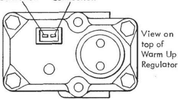
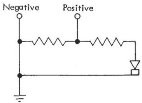
16. Auxiliary Air Valve
Location: Inlet manifold
Mating connector colour: Black. Additional information see LD 9.
Electrically operated air valve. Feed 12 volts positive from the R.P.M. relay.
17. Thermal Time Switch
Location: Screwed into water jacket inlet manifold
Mating connector colour: Brown. Additional information see LD 8.
Electrical/thermal switch which control the time period the cold start injector is operating during engine cranking.
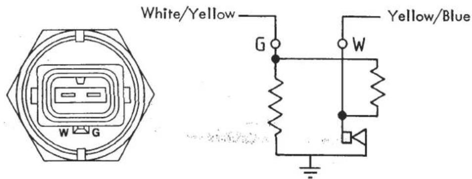
| Design | At a temperature | Resistance measurement in ohms between | |||
| under°C | over°C | Therm 'G' and 'Ground' (Housing) | Term 'W' and 'Ground' | Term 'G' and term 'W' | |
| 38°C/8s | +30 | 25...40 | 0 | 25...40 | |
| +40 | 50...80 | 100...160 | 50...80 | ||
18. Cold Start Injector
Location: Cold start adaptor, inlet manifold
Mating connector colour: Blue. Additional information see LD 7.
Electrically controlled injector. Positive feed supplied from cold start contact of starter motor during cranking, negative supplied by the thermal time switch to control injection period.
19. Throttle Position Switch
Location: Rear of throttle body spindle
Mating connector colour: Black. Additional information see LD 15 & LD 16.
A two contact rotary switch used to ground the fuel by-pass control relay windings at closed throttle and ground both pin 7, of the electronic control unit, and contact 87, of the idle change over relay at a throttle opening of 29° and above.
Schematic shown in closed throttle position
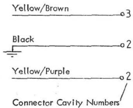
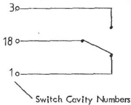
20. Frequency Valve
Location: Front of mixture control unit
Mating connector colour: White. Additional information see LD 14.
Electrically controlled fuel valve. Receives positive feed from the R.P.M. relay and the negative is controlled by the electronic control unit.
Although the frequency valve itself is not polarity conscious for correct operation of the test equipment i.e. duty cycle meter, it is essential that the cables into the connector are in the correct orientation, shown below.
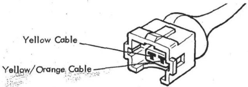
21. Electronic Control Unit
Location: Inside cabin mounted to the bulkhead behind the dirver's seat Mating connector colour: Black. Additional information see LD 15.
Electronic control unit for exhausts emission control. This unit processes information supplied by various sensors/switches and controls the operation of the frequency valve.
Connect as below. (Cavity numbers are moulded into connector)
Cavity 2 Cable to Lambda probe ) car-axial cable
Cavity 4 Screen for Lambda probe cable)
Cavity 5 Unit ground. Black cable to ground at engine via wiring harnesses.
Cavity 6 Yellow/black cable grounded at idle via the idle change over relay and fuel by-pass control relay to give a faster update time and therefore stabilises idle speed.
Cavity 7 Yellow/brown cable. Give a fixed duty cycle of 65% when grounded by the idle change over relay and fuel by-pass relay under deceleration, and the throttle position switch on throttle openings of 29° and above. Also at engine speeds over 3250 rpm.
Cavity 8 Yellow cable. 12 volts positive supply to electronic control unit from the R.P.M. relay.
Cavity 12 Yellow/red cable switched to ground, to give a 75% duty cycle, by the low temperature switch.
Cavity 15 Yellow/orange cable controls the duty cycle (open/close ratio) of the frequency valve.
Cavity 16 Unit ground. Black cable to ground at engine via wiring harnesses.
22. Fuel Pumps
Location: Underside of body R.H. rear. Additional information see LD 3. Twin fuel pump installation electrically connected in parallel through individual fuses, the engine overspeed/fuel pump failure module, and fuel pump control relays.
23. Inertia Switch
Location: Coil box
Mating connector colour: Grey
The safety inertia switch is designed to operate on impact, such as would occur in an accident, to disconnect the fuel pumps and minimise any fire hazard.
To reset the switch, in the event of its tripping, press down the reset plunger on the top.
- Engine Overspeed/Fuel Pump Failure Module
Location: Top of right hand tank board. (Under filler neck)
Mating connector colour: Natural. Additional information see LD 3.
The module senses low tension ignition pulses and supplies a negative to the fuel pump control relay winding.
In the event of excessive engine speed (7,000 ± 50 R.P.M.) this feed is removed thereby stopping the injection system operating and limiting engine R.P.M. Also in the event of one of the two fuel pumps failing to operate the maximum engine R.P.M. is restricted to 2,800 ± 50 R.P.M. This is achieved by monitoring the current drawn by each pump and removing the negative to the fuel pump control relay windings at 2,800 ± 50 R.P.M. in the event of one pump failing to draw any current. Therefore any part of the circuit between the module and the pump, going open circuit, will be detected and engine R.P.M. restricted. (This unit will therefore sense blown fuse, broken or disconnected fuel pump wiring.)
Disconnection of the module will not allow the fuel pumps to operate. Single pump failure may cause the fuse in the other pump circuit to blow due to the increased load imposed on it (dependent on position in which failed pump fails). This circuit is designed as a "get you home" aid in the event of failed fuel pump but the vehicle require attention to the fuel pump system as soon as possible.
- Fuel Pump Control Relays (2)
Location: Coil box
Mating connector colour: Black
Double contact relay (schematic as shown in item 1).
Controlled by the engine overspeed/fuel pump failure module, overboost switch and inertia switch. Switches positive feed, via 15 amp fuses to individual fuel pump circuits.
- Overboost Switch
Location: Coil box
Mating connector colour: White. Additional information see LD 3.
Supplies, via terminal 87b of the R.P.M. relay, a positive feed to the winding of the fuel pump control relay. This feed is removed, thereby de-energising the fuel pumps, in the event of an engine fault condition of excessive turbo boost pressure.
- Fuel Enrichment Module
Location: Top of right hand fuel tank board.
Mating connector colour: White. Additional information see LD 27 - 10
Senses engine speed of 3250 rpm via negative feed from ignition coil, and switches ignition feed to operate relay coil and close relay contacts. This provides earth signal to E.C.U. terminal 7.
ELECTRICAL
SECTION MB - ESPRIT S3 & TURBO (Dom/Row)
| Section | Sheet/Page | |
| Circuit Diagrams: | MB.1 | |
| S3 - Lumenition & Fused Fan Relay | LSL 249 | |
| S3 - A/C, Constant Energy & Thermal Trip | LSL 250 | |
| S3 - A/C, EEC (Symbol) Switches | LSL 251 | |
| S3 - From VIN 85D2153 (July '85) | LSL 254 | |
| S3 - '87 M.Y. onwards | LSL 259 | |
| Turbo - Commemorative, Lumenition | LSL 239 | |
| Turbo - Constant Energy, Fused Fan Relay | LSL 247 | |
| Turbo - Constant Energy, Thermal Trip | LSL 248 | |
| Turbo - '87 M.Y. onwards | LSL 258 | |
| Component Location Diagram | MB.2 | 9/9A |
| Harness Routing Diagram | MB.3 | 10 |
| Lumenition Ignition System | MB.4 | 11 to 14 |
| Lucas Constant Energy Ignition | MB.5 | 15/16 |
| 'Maintenance Free' Battery Charging | ||
| Procedure | MB.6 | 17 |
| Dim-Dip Headlamp System (U.K. models) | MB.7 | 18/19 |

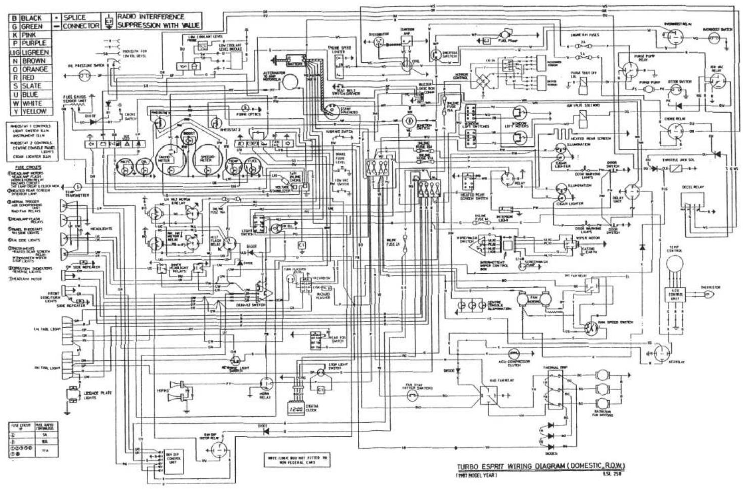
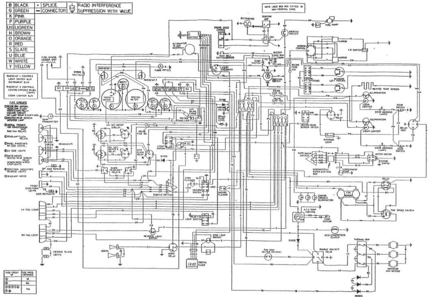
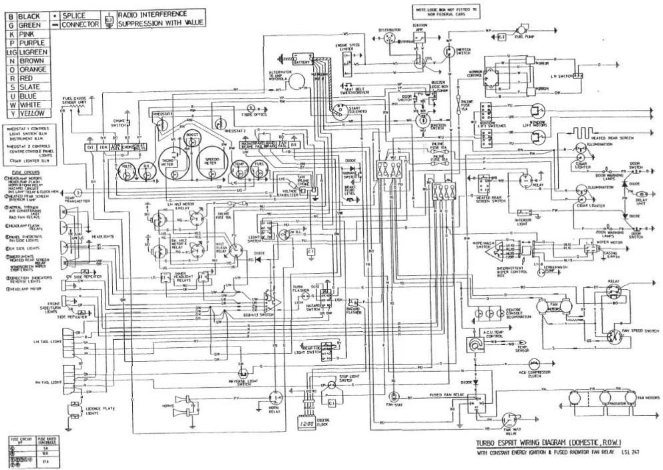
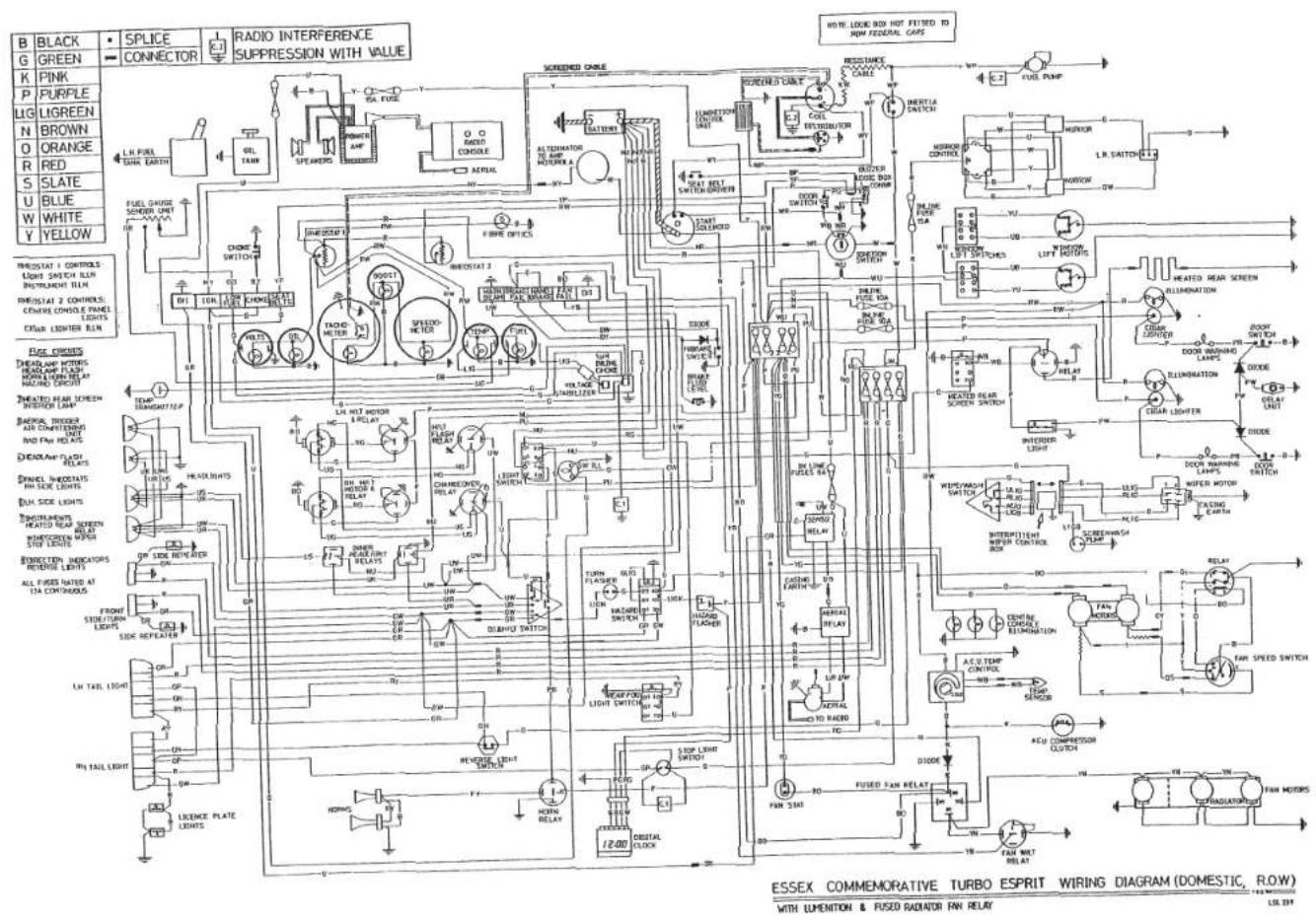

ECCDDIT CO WTRING, PRADEAM ECOM VIM BE D 2153, BE AVERGUE, 000
![graph TD A["Black"] --> B["SPLICE"] C["Green"] --> D["CONNECTOR"] E["PINK"] --> F["L. L. FUEL TAIR.EARTH"] G["LILAC"] --> H["N. BROWN"] I["LIG Green"] --> J["O ORANGE"] K["R RED"] --> L["S SLATE"] M["U BLUE"] --> N["W WHITE"] O["Y YELLOW"] --> P["THYF TRANSFITER"] Q["HANDBRAKE MACD SWITCH"] --> R["B…](/content/2026/05/1021120/images/45cf3d68de255c5568b8f4d52cbfe21ead65e8bc7b1796acc692dc3e2dae4ed4.jpg)
S3 ESPRIT WIRING DIAGRAM (DOMESTIC, R.O.W.) WITH ACU. WITH CONSTANT ENERGY IGNITION & RAD FAN THERMAL TRIP, & EEC (SYMBOL) SWITCHES 156 297


S3 ESPRIT WIRING DIAGRAM (DOMESTIC, R.O.W.) WITH ACU. WITH CONSTANT ENERGY IGNITION & RADIATOR FAN THERMAL TRIP LSL 250
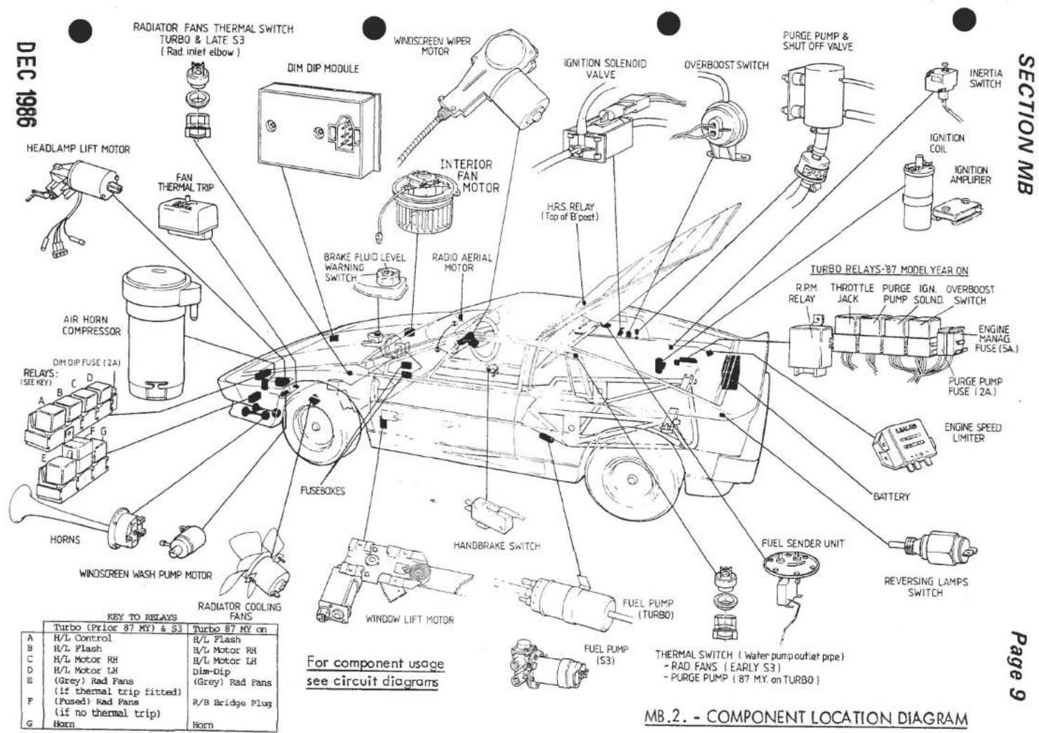
DEC 1986

MB.2.-COMPONENT LOCATION DIAGRAM-Fascia
DEC 1986
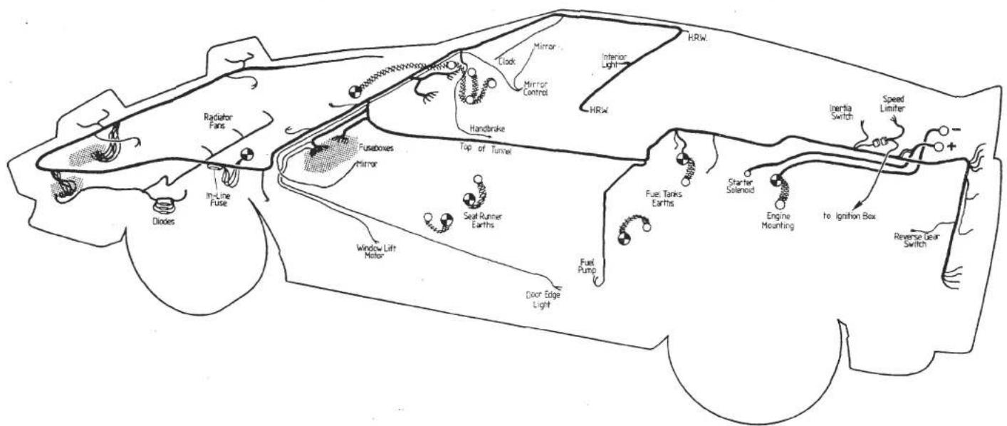
MB.3.- HARNESS ROUTING DIAGRAM
Page 10
SECTION MB
MB.4.- LUMENITION IGNITION SYSTEM
Early Series 3 and Turbo models used Lumenition infra red solid state contact breakerless ignition. On early Turbo models, the Lumenition power module was mounted on the engine bay side of the right hand fuel tank well, but was moved on introduction of the Esprit S3, to the ignition box at the rear of the engine bay.
An optical switch is fitted in the otherwise standard distributor and is operated by a 4 - blade chopper fitted over the distributor cam. A special fibre washer is sometimes used below the chopper blade to achieve the correct blade height through the optical switch.
Two types of Lumenition system have been used, the earlier Mk 16 type being superceded by the Mk 17 type, during 1980 as a running change on production. Components of either type are not individually compatible.
Identification - Power Module
Identification of power modules is only possible by the colour of the resin or plastic block sealing the wires into the module unit.
Mkl6 units are sealed with red or black resin. Mkl7 units are sealed by a white plastic clamp.
- Optical Switch
MK 16 optical switch units are marked with numbers similar to 8240, the 8 and 0 being the year and 24 the week of production.
Mk 17 optical switch units were also produced in 1980 but have a 17 preceding the number i.e. 17 8240.
All units produced in 1981 are Mk 17 with numbers similar to 8124, with 81 being the year and 24 the week of production. In the event of an ambiguous date code (e.g. 8120) contact the Lotus Service Department for advice.
Replacement
If a new power module for a Mk 16 system is required, it can only be replaced with a Mk 17 power module in conjunction with a Mk 17 optical switch.
If a Mk 16 optical switch is to be replaced, it can only be replaced with a Mk 17 optical switch, which, if the Mk 16 power module is to be retained, will necessitate the use of convertor unit A083M6305F fitted between the Mk 16 power module and Mk 17 optical switch.
Summary:
| Power Module Type | Part Number | Connector Block Shape | Colour of Seal | Length of Lead * | Compatible Optical Switch |
| Mk 16 (No longer available) | A075M0335F | Rectangular | Red or Black | 790 mm | A907E6331F (Mk 16) or B907E6331F (MK 17) + A083M6305F (Convertor) |
| Mk 17 | A083M0384F | Oval or Rectangular | White | 790 mm | B907E6331F (Mk 17) |
| Mk 17 | B083M0384F | Oval or Rectangular | White | 470 mm | B907E6331F (Mk 17) |
* With power module by RH fuel tank - 790 mm With power module in ignition box - 470 mm
Connector Blocks
Mk 16 systems used a rectangular connector block between the optical switch and power module. Mk 17 systems used an oval connector block with retaining prongs, which was subsequently found to be less durable than the earlier rectangular type.
All service replacement components are supplied fitted with the rectangular type connector, and include the opposite 'half' of the connector block which may be used if necessary to replace the remaining oval connector. viz:-
- Use special tool T000T0473 to close locking tag on pin and remove from wire end of connector block by pulling. MOST IMPORTANT - open tag to original locking angle.

- Having made certain tags are in locking position, push each pin in the correct tunnel of the new connector block until the tag clicks into position.
The connector is numbered as illustration

NOTE: On no account must Mk 17 power modules be connected with Mk 16 optical switches. Also, Mk 16 modules must not be connected to Mk 17 optical switches without use of adaptor A083M6305F.
TESTING INSTRUCTIONS FOR "LUMENITION" MK 16 AND MK 17 IGNITION SYSTEMS
All tests are carried out with ignition switched on and centre HT lead removed from the distributor and held approximately 6.5 mm (1/4 inch) from an earth point such as the engine, but away from the carburettors region.
CAUTION: HT can be dangerous and can jump 25 mm (1 inch). Leads should be handled carefully.
- To test the complete system -
With the distributor cap removed and out of strong sunlight, pass a piece of opaque material, such as a piece of black card between the lenses of the optical switch - this should produce a spark from the HT lead to earth.
- To test power module (and coil) -
a). Unplug 3-way connector leading to the distributor.
b). Connect (by means of a small piece of wire) -
On Mk 16 the blue to the red On Mk 17 the blue to the black
wire leading to the power module. As this connection is made a spark is produced at the HT lead. If no spark is produced the power module is suspect. If a weak spark is produced - the coil may be suspect.
3. To test the optical switch -
The optical switch must be connected to a good power module. With a sensitive voltmeter measure the voltage between blue and black leads. With infra red beam not interrupted, the voltage is approximately -
Mk 17 (2.7V) Mk 16 (1.8V) - this drops to Mk 17 (1.0V) Mk 16 (0.3V) - with beam interrupted.
N.B. The voltage on the red lead is approximately 7.5V.
4. Do not leave the ignition on for a long time (max 15 mins) with the optical switch assembly disconnected.
NOTE: Under no circumstances should:
a). A full positive feed be applied to any connection other than the red positive wire of the power module supplied with a male Lucas terminal.
b). The coil terminals be short circuited or the brown wire (coil - VE) of the power module be connected to full positive feed.
Failure to observe the notes above will result in catastrophic damage to the power module, invalidating the warranty.
MB.5. - LUCAS CONSTANT ENERGY IGNITION
The Lucas constant energy ignition system is an inductive system in which the energy stored in the coil is maintained constant over a wide range of engine speeds, thereby providing consistently high output voltages. The system comprises a distributor model 45 DM, and ignition coil model 32 C5, an ignition amplifier model AB 14 and an electronic rev. limiter.
The distributor incorporates a variable-reluctance position transducer (pick up) to provide a basic timing waveform. The sintered reluctor has four projections which correspond in function with the cam lobes of a conventional distributor. The pick up comprises a coil and magnet assembly, the pick up air gap (0.20 - 0.35 mm.) being set during manufacture and requiring no subsequent adjustment.
A conventional type rotor arm is fitted, moulded (as is the distributor cap) from track retardant material. The two cables connecting the distributor to the ignition amplifier terminate in a non-reversible "shur plug".
The high energy coil (model 32 C5) is specially designed to achieve the very fast current rise times required for this system. The coil requires no ballast and consumes no current in the stalled engine condition.
The ignition amplifier (AB14) is mounted in the ignition box whilst the electronic rev. limiter unit is fitted on the RH fuel tank board.
The ignition must be switched on for the following checks.
| TEST | RESULT | |||
1 CHECK HT SPARKING |  | |||
| -XAW7] |  | |||
| 1 | 2 | 3 | 4 | SUSPECT |
| LOW | √ | √ | √ | Battery discharged |
| √ | LOW | LOW | √ | Ignition switch and/or wiring |
| √ | √ | LOW | √ | Coil or amplifier |
| √ | √ | √ | HIGH | Amplifier earth (ground) |
3 CHECK AMPLIFIER SWITCHING | Voltage increaseswhile cranking——TEST 5Voltage does not increasewhile cranking——TEST 4 |
4 PICK-UP COIL RESISTANCE | Ohmmeter should show2-5 kΩCorrectChange amplifierIf engine will not start——TEST 5IncorrectChange pick-upIf engine will not start—— |
5 CHECK HT SPARKING | Should be good HT sparkingRepeat with original HT leadGood sparkingIf engine will not start—— No sparking, replace HT leadIf engine will not start——TEST 6No sparkingReplace coilIf engine will not start—— No sparking, replace HT leadIf engine will not start——TEST 6No sparkingReplace coilIf engine will not start—— |
6 CHECK ROTOR ARM | Should be:No sparking—— HT sparkingReplace rotor arm/rotor vaneIf engine will not start—— HT sparkingReplace rotor arm/rotor vaneIf engine will not start—— |
| 7 VISUAL AND HT CABLE CHECKSEXAMINE1 Distributor Cover2 Coil Top3 H.T. Cable Insulation4 H.T. Cable Continuity5 Spark Plugs | Should be:1 Clean, dry, no tracking marks2 Clean, dry, no tracking marks3 Must not be cracked, chafed or perished4 Must not be open circuit5 Clean, dry, and set to correct gap |
Recommended Test Equipment
DC moving coil voltmeter, scale 0 - 20V DC moving coil ohmmeter HT jumper cable
MB.6.- 'MAINTENANCE FREE' BATTERY CHARGING PROCEDURE
Instructions for Tungstone Powermaster Maintenance Free Batteries.
To determine the state of charge of the battery, apply a brief discharge of no more than ten seconds duration (e.g. turn on headlights) with the engine off, and then allow to stand on open circuit for two to three minutes.
Measure the terminal voltage of the battery.
If steady voltage is below 12.4 Volts, recharge battery as follows.
Note: The battery must not be boost charged.
If necessary, fit a replacement battery to the vehicle, whilst original battery is charged as follows.
Remove battery from vehicle.
a). Constant Current: The battery must be charged at a maximum of 5 amps until the battery terminal voltage (on charge) has stabilised over a one hour period, at which time the voltage will be in the range 16.0 - 16.5 V. At this stage the battery must be taken off charge IMMEDIATELY, to prevent excess gassing with resulting water loss which will ultimately reduce the guaranteed service life.
b). Constant Voltage: The battery may be charged at a voltage up to a maximum of 15.8V providing the current is carefully monitored and the charge terminated when the current has tapered off and changes by less than 0.1 amp over a period of one hour. If it is not possible to monitor the current during charging, then the voltage must be restricted to 14.4 V maximum.
MB.7. - DIM-DIP HEADLAMP SYSTEM (U.K. Models)
The Motor Vehicles (Dim-Dip Lighting Devices) Regulations 1983 of the Road Traffic Act, decrees that cars manufactured on or after 1st October 1986 for use in the U.K. and first registered on or after 1st April 1987, shall be fitted with Dim-Dip lighting systems.
The Dim-Dip system must operate as follows:
If, with the vehicle sidelamps lit, the ignition is switched on, the headlamp dip beams (halogen) will operate on a reduced current to provide 10% of their normal intensity.
All 1987 Model Year Domestic cars are fitted with Dim-Dip systems which operate as follows:
The lighting switch is located at the left hand top of the fascia binnacle.
With this switch is the 'up' position, all lights are off.
In the centre position, the side, rear and panel lights are switched on. On U.K. market cars fitted with 'Dim-Dip' headlamps switching on the ignition will raise the headlamp pods with the dip beams operating in 'dim' mode.
With the switch in the 'down' position the headlamp pods are raised with the headlamps lit.
Dip and flash control is unchanged and operates as previously.
Component Location
The dim-dip module is mounted inboard of the right hand headlamp pod well, and the fuse and relay alongside the existing headlamp relays, behind the left hand pod.


i) With sidelamps switched on, a feed is supplied to module terminal 1 and the relay is energised.
ii) When the ignition is switched on, a feed is supplied through the energised relay to the headlamp motors to raise the pods. In addition, a feed is supplied to module terminal 7. The module processes the signals received via terminals 1 and 7 to output a 10% voltage feed to the dip beams via terminal 5.
iii) With the headlamps switched on, a feed from the headlamp switch is supplied to module terminal 2. When dip beam is selected, an additional feed is supplied to module terminal 3. The module processes the signals received and either supplies no output to terminal 5 (when main beam is operating) or full voltage (when dip beam selected).
ELECTRICAL
SECTION MC - ESPRIT TURBO U.S.A. (Prior to '86 M.Y.)
Sheet/Page
Circuit Diagrams:
| Component Index | - |
| Legend | - |
| Supplies | 1 |
| Start, Alternator, Ignition | 2 |
| Engine Management & Operation | 3A/B/C/D/E/F |
| Choke Switch & Fuel Level | 4 |
| Radiator Cooling Fans | 5 |
| Air Conditioning | 6 |
| Internal Fans | 7 |
| Headlamp Beam, Dip, Flash | 8 |
| Horns, Beam, Dip & Column Switch Supply | 9A |
| Headlamp Motor Operation | 9B/C/D/E/F |
| Direction Indicators & Hazard | 10 |
| Rear Lights, Instrument Illumination | 11 |
| Clock, Door Lamps, Interior Lamps, Cigar Lighter | 12 |
| Stop Lights Reverse Lights | 13 |
| Wipers, Washer & Powerwash | 14 |
| Brake Fail & Handbrake Warning | 15 |
| Seat Belt Logic, Water & Battery Gauges | 16 |
| Heated Rear Screen | 17 |
| Window Lift | 18 |
| Mirrors | 19 |
| Radio & Radio Amp (if fitted) | 20 |
| Pulsafe Alarm (if fitted) | 20A |
| Alarm Components Location | 20B |
| Engine Bay Ventilation | 21 |
| Fuse Box, Circuits & Ratings | 22 |
| Relay Connections | 23 |
| Splice 'G' | 24 |
| Splice 'A' | 25 |
| Splice 'B' | 26 |
| Splice 'D' | 27 |
| component Location Diagram | 28 |
| arness Routing Diagram | 29 |
| instrument Binnacle Removal | 30 |
| ucas 'Constant Energy' Ignition | 30 to 32 |
| battery Re-charging Procedure | 33 |
SECTION MC
COMPONENT INDEX
| Sheet/ | |
| A.C.U. Compressor | 6 |
| A.C.U. Tem. Control | 5 |
| A.C.U. Thermistor | 5 |
| Alternator | 2 |
| Battery | 2 |
| Cigar Lighters | 12 |
| Clock | 12 |
| Distributor | 2 |
| Engine Speed Limiter | 2 |
| Fuel Sender Unit | 4 |
| Fuse Box | 22 |
| Heated Rear Screen | 17 |
| Ignition Amplifier | 2 |
| Ignition Coil | 2 |
| Intermittent Wipe Unit | 14 |
| Instruments - Battery Condition | 16 |
| - Fuel Gauge | 14 |
| - Tachometer | 2 |
| - Temp Gauge | 16 |
| Inverter, D.I. Warning Control | 10 |
| Lights - Brake Fail Warning | 15 |
| - Door Warning | 12 |
| - D.I. & Hazard Lamps | 10 |
| - D.I. Warning | 10 |
| - Fan Fail Warning | 5 |
| - Handbrake Warning | 15 |
| - Headlamps | 8 |
| - Ignition Warning | 2 |
| - Instrument Illumination | 11 |
| - Interior Lamp | 12 |
| - Low Fuel/Choke Warning | 4 |
| - Licence Plate Lamps | 11 |
| - Panel Lights | 12 |
| - Reverse Lamps | 13 |
| - Seat Belt Warning | 16 |
| - Side Marker, Front | 10 |
| - Side Marker, Rear | 11 |
| - Stoplamps | 13 |
| - Tailamps | 11 |
| Mirrors | 19 |
| Mirror Control Unit | 19 |
| Motors - Antenna | 20 |
| - Engine Bay Vent Fan | 21 |
| - Headlamp | 19 |
| - Internal Fans | 7 |
| - Radiator Cooling Fans | 5 |
| - Window Lift | 18 |
| - Windscreen Wiper | 14 |
| Pumps - Fuel | 2 |
| - Headlamp Wash | 14 |
| - Screen Wash | 14 |
| Radio | 20 |
| Sheet/T | |
| Radio Amp. (if fitted) | 20 |
| Relays - ACU Control | 6 |
| - Brake Fail | 15 |
| - Dip Beam | 8 |
| - D.I. & Hazard Unit | 10 |
| - Engine Bay Vent | 21 |
| - Engine Management | 3 |
| - Flash | 8 |
| - Headlamp Motors | 9 |
| - Heated Rear Screen | 17 |
| - Horn | 9 |
| - Internal Fans | 7 |
| - Lamp Delay Unit | 12 |
| - Main Beam | 8 |
| - Power (aux.) | 1 |
| - Power (ign.) | 1 |
| - Radiator Cooling Fans | 5 |
| Rheostats | 11 |
| Solenoids - Carb. Evap. | 3 |
| - Cold Start Changeover | 3 |
| - Divertor Valve | 3 |
| - Fuel Pressure | 3 |
| - Starter | 2 |
| - Throttle | 3 |
| Speakers | 20 |
| Switches - Mirror Changeover | 19 |
| - Choke | 4 |
| - Door | 12 |
| - Column, Dip/Beam | 8 |
| - Handbrake | 15 |
| - Hazard | 10 |
| - Heated Rear Screen | 17 |
| - Ignition | 2 |
| - Inertia | 2 |
| - Internal Fans, speed | 7 |
| - Isolator (engine bay vent) | 21 |
| - Lights | 8 |
| - Low Brake Fluid | 15 |
| - Low Pressure Cut-Out (ACU) | 5 |
| - Low Vacuum (brakes) | 15 |
| - Power Wash/Wipe | 14 |
| - Revers Light | 13 |
| - Seat Belt | 16 |
| - Stop Light | 13 |
| - Thermal (engine management) | 3 |
| - Thermal (engine bay vent) | 21 |
| - Throttle Micro | 3 |
| - Window Lift | 18 |
| - Temp Transmitter | 16 |
| - Timer (engine bay vent) | 21 |
| - Voltage stabiliser | 4, 16 |


LEGEND
| BIN | Binnacle Connector |
| D.H.C. | Door Harness Connector |
| D.I. | Direction Indicator |
| E.B.C. | Engine Bulkhead Connector |
| E.H.C. | Engine Harness Connector |
| F.H.C. | Front Harness Connector |
| L.H. | Left Hand |
| P.H.C. | Pumps Harness Connector |
| R.H. | Right Hand |
| R.H.C. | Rear Harness Connector |
| SOL | Solenoid |
| S/W | Switch |
| W/LT. | Warning Light |
| C.C.C. | Centre Console Connector |
| M.H.C. | Manifold Harness Connector |
| C.F.H.C. | Cooling Fans Harness Connector |
Cable Colour Code
| B | Black | O | Orange |
| G | Green | R | Red |
| K | Pink | S | Slate |
| P | Purple | U | Blue |
| LTG | Light Green | W | White |
| N | Brown | Y | Yellow |
SHEET 1
![graph TD A["HEAD LAMP"] --> B["NU"] C["MAIN/DIP BEAM"] --> D["FHC"] E["CIRCUIT SEE SHT.8"] --> F["NU"] G["TO RAD. FAN"] --> H["N"] I["RELAY SEE SHT.5"] --> J["N"] K["TO IGNITION S/W. SEE SHT.2"] --> L["Y"] M["SPLICE 'B' SEE SHT.26"] --> N["SPLICE 'D' SEE SHT.27"] O["SPLICE 'A' SEE SHT.25"] --> P["N"…](/content/2026/05/1021120/images/f7845dae1f39f09fd35e9d510c5f0f1d3b0a623d06d884585cebcd39cef069cd.jpg)
SECTION MC
SUPPLIES
SHEET 1
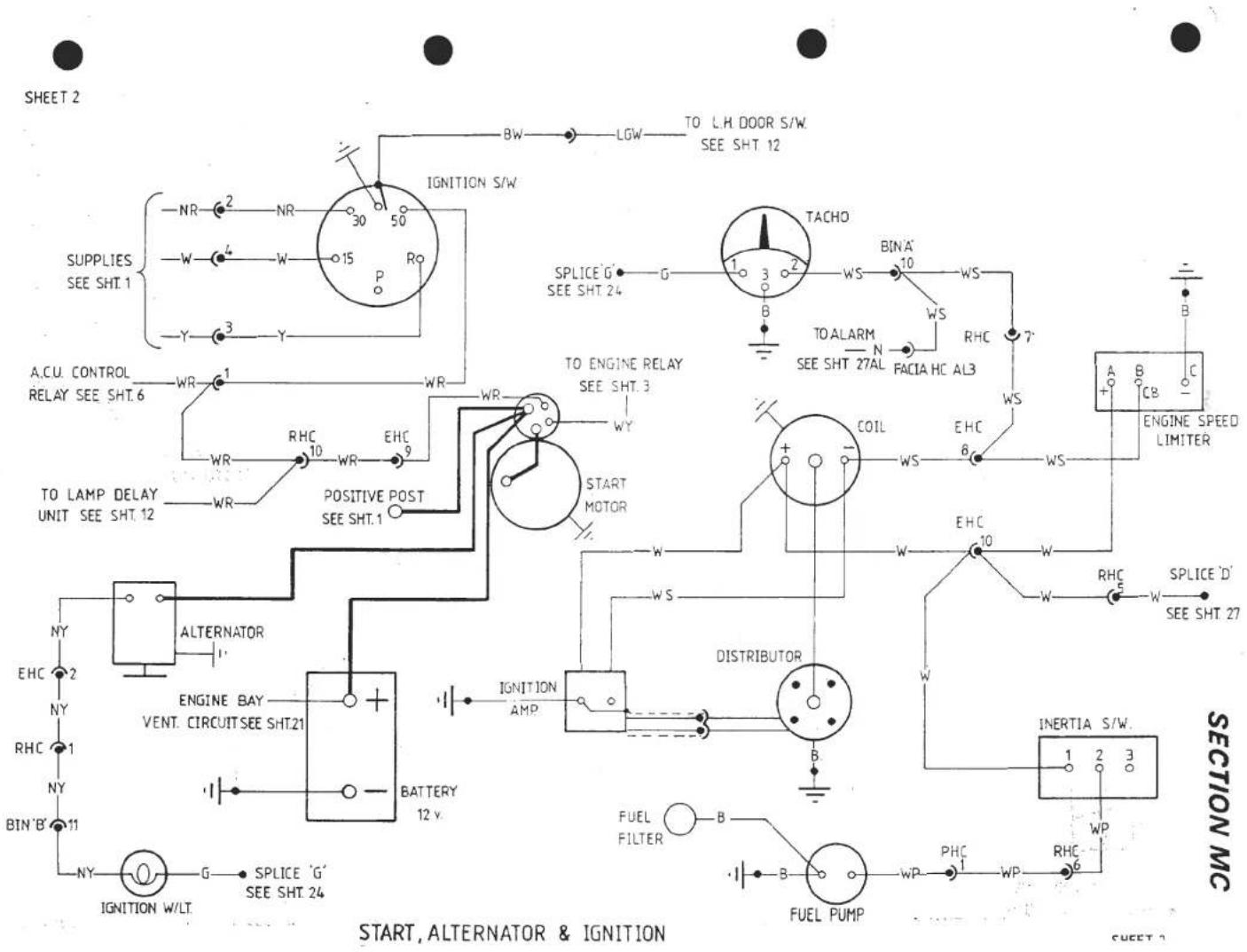
![graph TD A["TO STARTER MOTOR (COLD START)<br>SEE SHT. 2"] --> B["ENGINE RELAYS"] B --> C["SEE CHoke S/W & FUEL<br>LEVEL CIRCUIT ON SHT. 4"] C --> D["COLD START<br>CHANGE OVER<br>SOL."] D --> E["YN"] E --> F["MHC 1"] F --> G["YN"] G --> H["SECTION MC"] H --> I["YP"] I --> J["RHC 10"] J --> K["FUSE BO…](/content/2026/05/1021120/images/4a74cea3b7e8c5237a3188e30769d4428e67fcbfe4b1912f0949788380ba86b0.jpg)
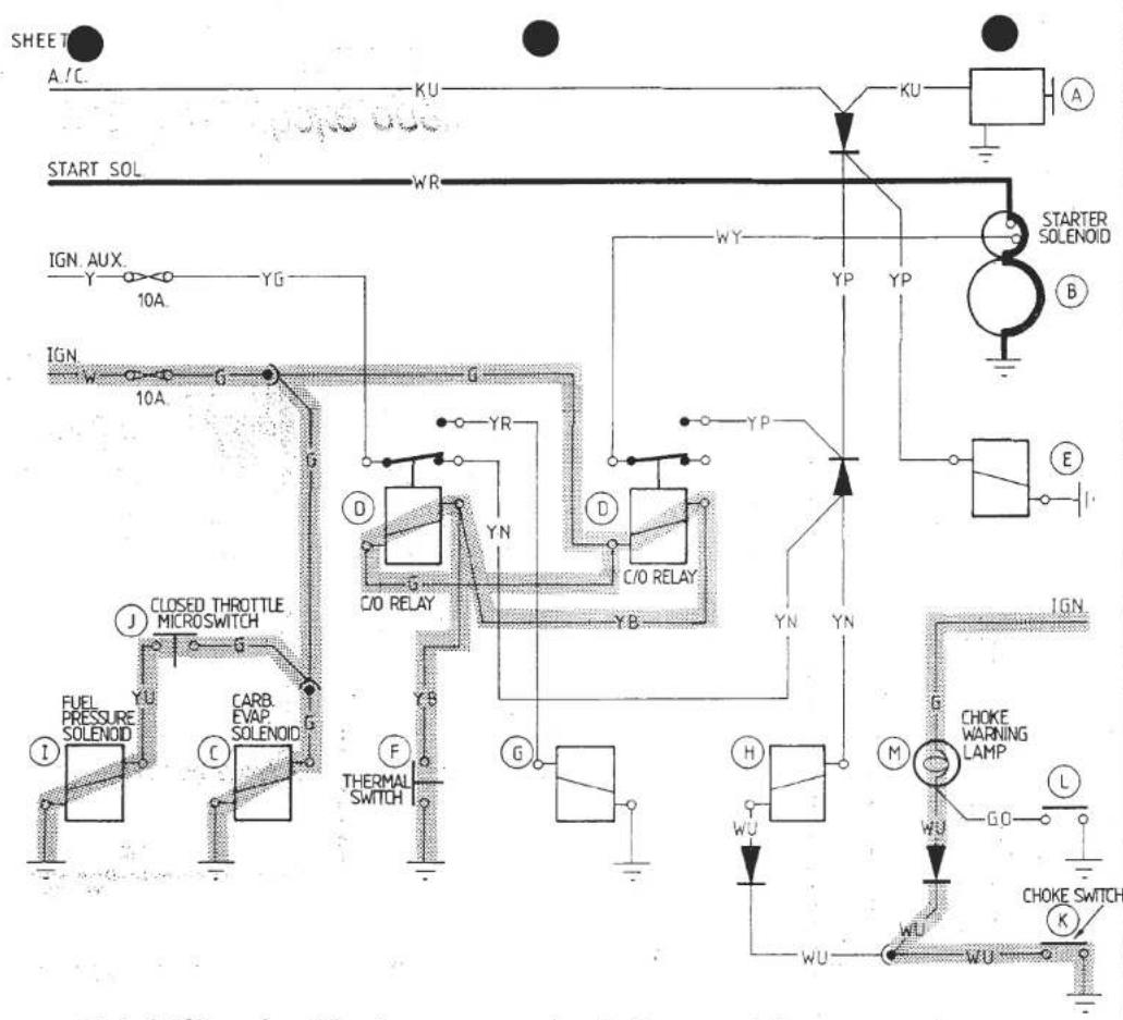
Cold Start. Choke operated & cranking
ENGINE MANAGEMENT CIRCUIT - FEDERAL
SHEET 3B
ENGINE MANAGEMENT OPERATION
A A/C. COMPRESSOR.
B STARTER MOTOR.
C CARB. EVAP. SOLENOID:
CLOSED WHEN
IGNITION OFF, OPEN WHEN IGNITION ON
D TEMP CHANGE OVER RELAYS:
CONTROLLED BY THERMAL SWITCH 'F'
E THROTTLE SOLENOID: TO OPERATE WHEN;
1. A/C. COMPRESSOR IS ENERGISED.
2. STARTER MOTOR CRANKING ON HOT START.
3. COLD STARTING EXCEPT DURING CRANKING
F THERMAL SWITCH:
MAX. BREAK ON RISE 70°C.
MIN. MAKE ON FALL 60°C.
G DIVERTER VALVE:
ENERGISED WHEN COOLANT TEMP ABOVE 60°C
H COLD START CHANGE OVER SOLENOID: ENERGISED WHEN CHOKE IS USED BUT NOT WHilst CRANKING.
I FUEL PRESSURE SOLENOID:
ENERGISED BY THROTTLE MICRO SWITCH 'J'
J THROTTLE MICRO SWITCH.
K CHOKE SWITCH
L LOW FUEL SWITCH
M CHOKE/LOW FUEL WARNING LAMP

Cold Run -choke operated
ENGINE MANAGEMENT CIRCUIT - FEDERAL
SHEET 3C
ENGINE MANAGEMENT OPERATION
A A/C. COMPRESSOR.

B STARTER MOTOR
C CARB. EVAP. SOLENOID:
CLOSED WHEN
IGNITION OFF, OPEN WHEN IGNITION ON.
D TEMP CHANGE OVER RELAYS:
CONTROLLED BY THERMAL SWITCH 'F'
E THROTTLE SOLENOID: TO OPERATE WHEN;
-
A/C. COMPRESSOR IS ENERGISED.
-
STARTER MOTOR CRANKING ON HOT START.
3.COLD STARTING EXCEPT DURING CRANKING.
F THERMAL SWITCH:
MAX. BREAK ON RISE 70° C.
MIN. MAKE ON FALL 60°C.
G DIVERTER VALVE
ENERGISED WHEN COOLANT TEMP ABOVE 60°C
H COLD START CHANGE OVER SOLENOID:
ENERGISED WHEN CHOKE IS USED BUT NOT WHilst CRANKING.
I FUEL PRESSURE SOLENOID:
ENERGISED BY THROTTLE MICRO SWITCH 'J'
J THROTTLE MICRO SWITCH.
K CHOKE SWITCH.
L LOW FUEL SWITCH.
M CHOKE/LOW FUEL WARNING LAMP

Cold Run (below 70°C.)
ENGINE MANAGEMENT CIRCUIT - FEDERAL
SHEET 3D
ENGINE MANAGEMENT OPERATION
A A/C. COMPRESSOR.
B STARTER MOTOR
C CARB. EVAP. SOLENOID:
CLOSED WHEN
IGNITION OFF. OPEN WHEN IGNITION ON.
D TEMP CHANGE OVER RELAYS:
CONTROLLED BY THERMAL SWITCH 'F'
E THROTTLE SOLENOID: TO OPERATE WHEN;
1 A/C. COMPRESSOR IS ENERGISED.
2. STARTER MOTOR CRANKING ON HOT START.
3.COLD STARTING EXCEPT DURING CRANKING.
F THERMAL SWITCH
MAX. BREAK ON RISE 70°C.
MIN. MAKE ON FALL 60°C.
G DIVERTER VALVE
ENERGISED WHEN COOLANT TEMP ABOVE 60°C
H COLD START CHANGE OVER SOLENOID:
ENERGISED WHEN CHOKE IS USED BUT NOT WHilst CRANKING.
I FUEL PRESSURE SOLENOID:
ENERGISED BY THROTTLE MICRO SWITCH 'J'
J THROTTLE MICRO SWITCH.
K CHOKE SWITCH.
L LOW FUEL SWITCH
M CHOKE/LOW FUEL WARNING LAMP

Hot Run (above 70°C.)
ENGINE MANAGEMENT CIRCUIT - FEDERAL
SHEET 3E
ENGINE MANAGEMENT OPERATION

A A/C. COMPRESSOR.
B STARTER MOTOR.
C CARB. EVAP. SOLENOID:
CLOSED WHEN
IGNITION OFF, OPEN WHEN IGNITION ON.
D TEMP CHANGE OVER RELAYS: CONTROLLED BY THERMAL SWITCH 'F'
E THROTTLE SOLENOID: TO OPERATE WHEN:
1. A/C. COMPRESSOR IS ENERGISED.
2. STARTER MOTOR CRANKING ON HOT START.
3. COLD STARTING EXCEPT DURING CRANKING
F THERMAL SWITCH:
MAX. BREAK ON RISE 70°C.
MIN. MAKE ON FALL 60°C.
G DIVERTER VALVE:
ENERGISED WHEN COOLANT TEMP ABOVE 60°C
H COLD START CHANGE OVER SOLENOID: ENERGISED WHEN CHOKE IS USED BUT NOT WHILST CRANKING.
I FUEL PRESSURE SOLENOID:
ENERGISED BY THROTTLE MICRO SWITCH 'J'
J THROTTLE MICRO SWITCH.
K CHOKE SWITCH
L LOW FUEL SWITCH
M CHOKE/LOW FUEL WARNING LAMP
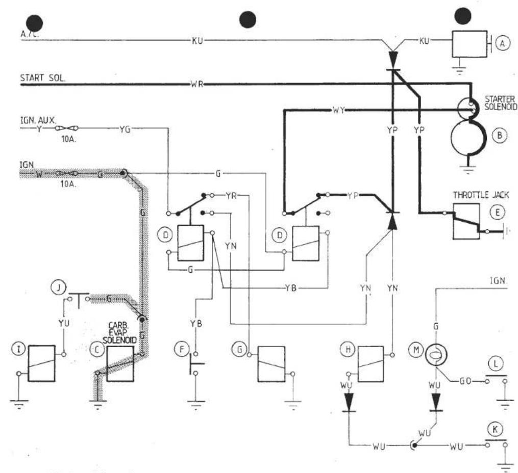
Hot Start
ENGINE MANAGEMENT CIRCUIT - FEDERAL
SHEET 3F
ENGINE MANAGEMENT OPERATION
A A/C. COMPRESSOR.
B STARTER MOTOR.
C CARB EVAP SOLENOID
CLOSED WHEN
IGNITION OFF, OPEN WHEN IGNITION ON.
D TEMP CHANGE OVER RELAYS:
CONTROLLED BY THERMAL SWITCH 'F'
E THROTTLE SOLENOID: TO OPERATE WHEN;
1 A/C. COMPRESSOR IS ENERGISED.
2. STARTER MOTOR CRANKING ON HOT START.
3.COLD STARTING EXCEPT DURING CRANKING
F THERMAL SWITCH
MAX. BREAK ON RISE 70° C.
MIN. MAKE ON FALL 60°C.
G DIVERTER VALVE
ENERGISED WHEN COOLANT TEMP ABOVE 60°C
H COLD START CHANGE OVER SOLENOID:
ENERGISED WHEN CHOKE IS USED BUT NOT WHILST CRANKING.
I FUEL PRESSURE SOLENOID
ENERGISED BY THROTTLE MICRO SWITCH 'J'
J THROTTLE MICRO SWITCH.
K CHOKE SWITCH.
L LOW FUEL SWITCH.
M CHOKE/LOW FUEL WARNING LAMP

SHEET 4
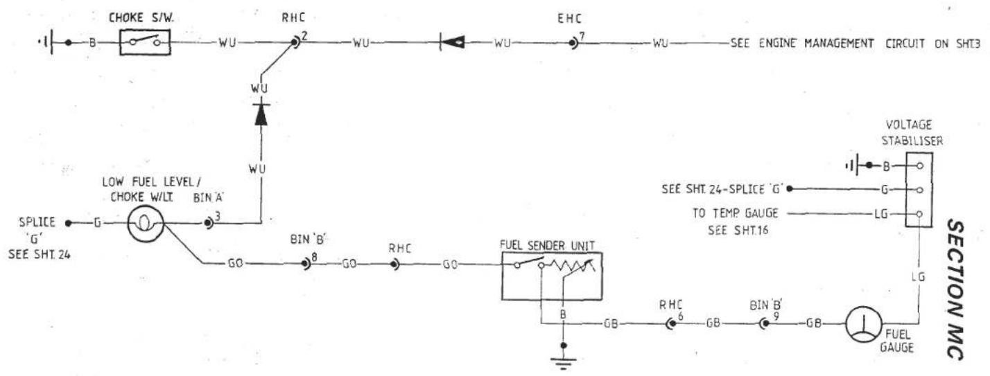
CHOKE S/W. & FUEL LEVEL
SHEET 4


RADIATOR COOLING FANS
SHEET 5
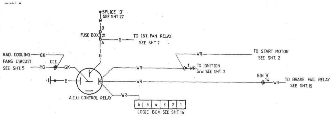
SECTION MC
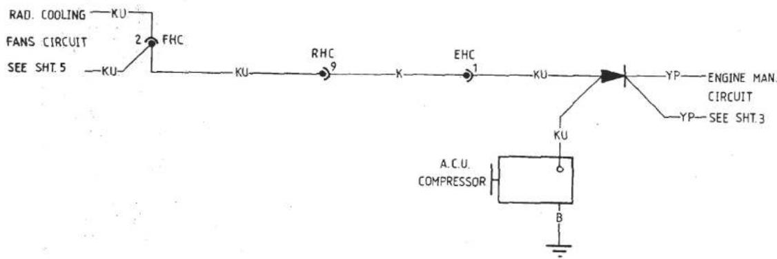
AIR CONDITIONING
SHEET 6


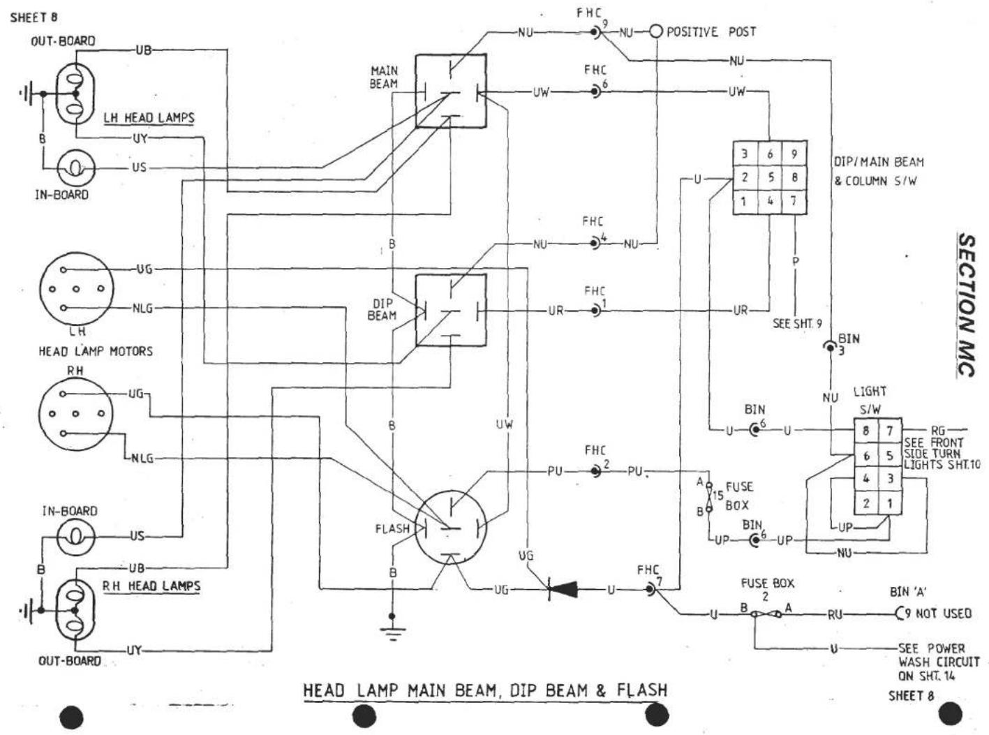


![graph TD A["Down MICRO-SWITCH"] --> B["UP MICRO-SWITCH"] B --> C["RH MOTOR RELAY"] C --> D["NLG"] D --> E["P"] E --> F["POSITIVE POST"] F --> G["10A N"] G --> H["PODS DOWN"] I["down MICRO-SWITCH"] --> J["UP MICRO-SWITCH"] J --> K["LH MOTOR RELAY"] K --> L["S"] L --> M["UG"] M --> N["UG"] N --> O["NL…](/content/2026/05/1021120/images/c7b5704c2b5f6415c39ea155c3cca046205cfe3941b871ea7e421621ef579524.jpg)
HEAD LAMP MOTOR CIRCUIT
SHEET 9B
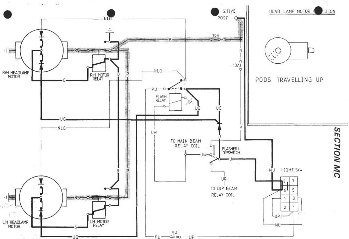
HEAD LAMP MOTOR CIRCUIT
SHEET 9C
![graph TD A["RH HEADLAMP MOTOR"] --> B["RG"] B --> C["RH MOTOR RELAY"] C --> D["B P"] D --> E["NLG"] E --> F["P"] F --> G["POSITIVE POST"] G --> H["10A N"] H --> I["N"] I --> J["10A"] J --> K["PODS UP"] L["LH HEADLAMP MOTOR"] --> M["RS"] M --> N["LH MOTOR RELAY"] N --> O["S UG"] O --> P["UG"] P --> Q…](/content/2026/05/1021120/images/c8036e50bbe0b77bb416486131cb5b5585dbb33f5f8e0f4cb90d5895220dd415.jpg)
HEAD LAMP MOTOR CIRCUIT
SHEET 90
![graph TD A["Head Lamp Motor Circuit"] --> B["RH HEADLAMP MOTOR"] A --> C["LH HEADLAMP MOTOR"] B --> D["RG"] D --> E["RH MOTOR RELAY"] E --> F["B"] F --> G["P"] G --> H["NLG"] H --> I["POSITIVE POST"] I --> J["10A N"] J --> K["PODS TRAVELLING DOWN"] K --> L["SECTION MC"] L --> M["UP"] M --> N["NU"] N…](/content/2026/05/1021120/images/8f58714fe4e4d3e5f081f8b907434b5baa14549a557e14ffa3a45b063a6221a4.jpg)
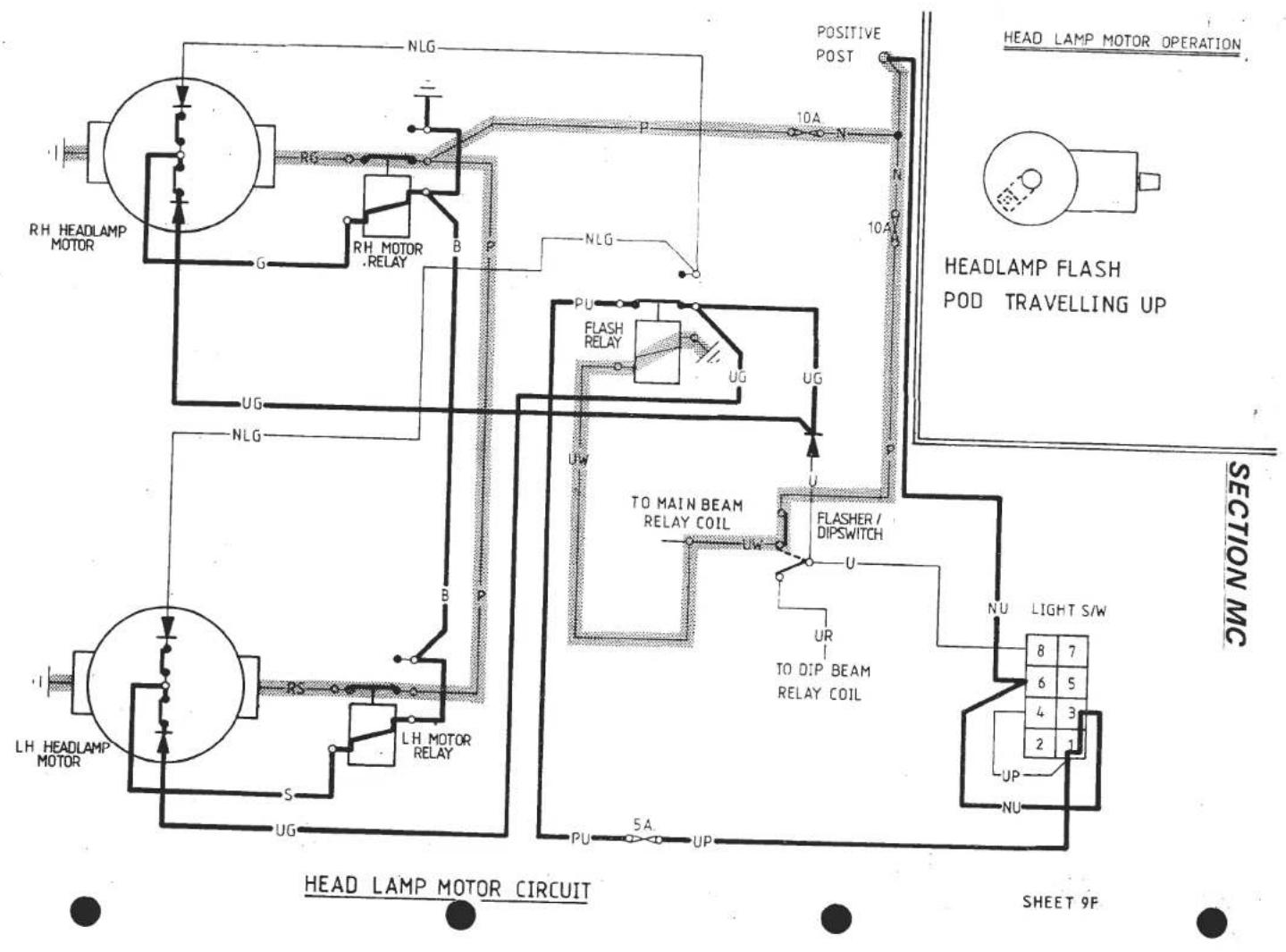

D.I. & HAZARD
SHEET 10

.REAR LIGHTS & INSTRUMENT ILLUMINATION
SHEET 11
SECTION MC

CLOCK, DOOR WARNING & INTERNAL LAMPS
SHEET 12
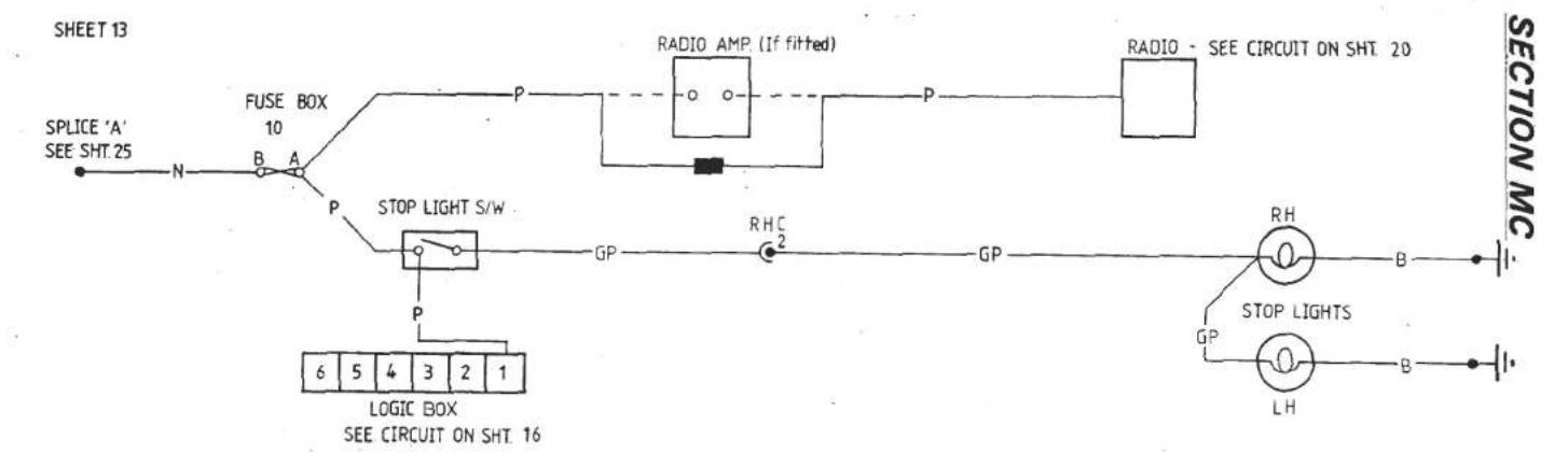
STOP LIGHT

REVERSE LIGHT
SHEET13


SHEET 15

SHEET 19
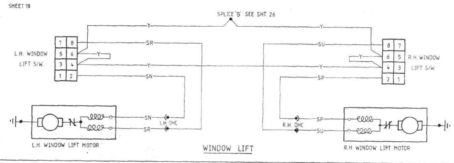
SECTION MC
SHEET 1.
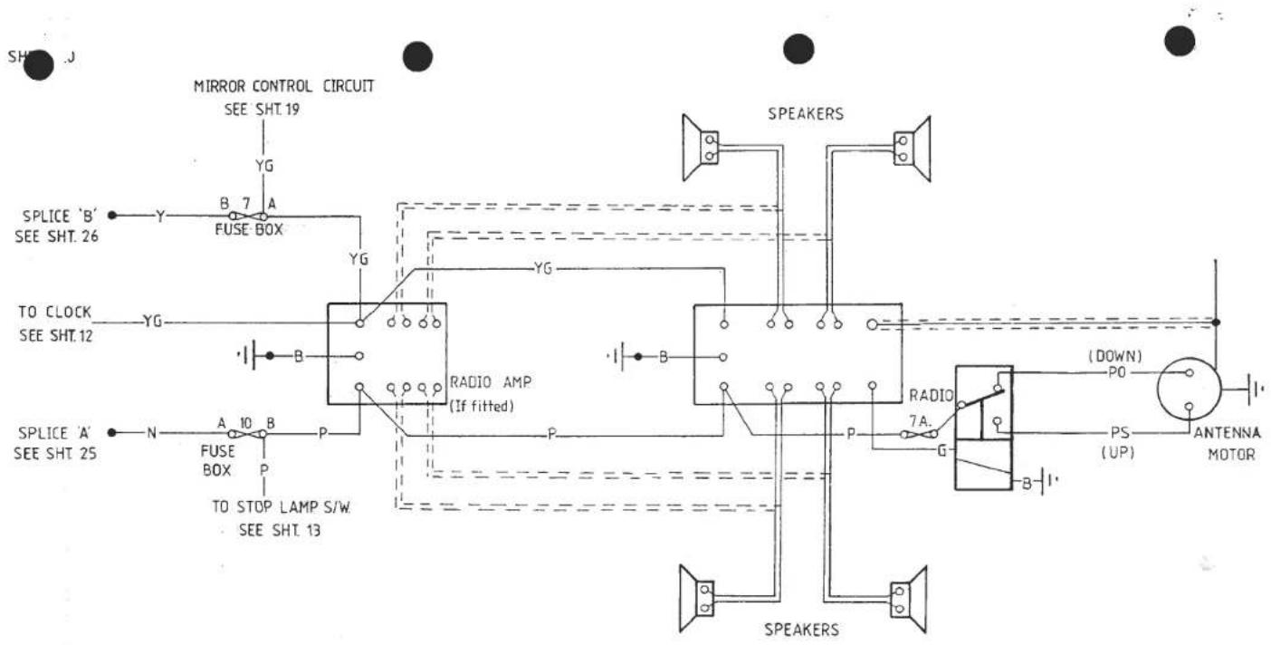
RADIO & RADIO AMP (If fitted)
SHEET 20
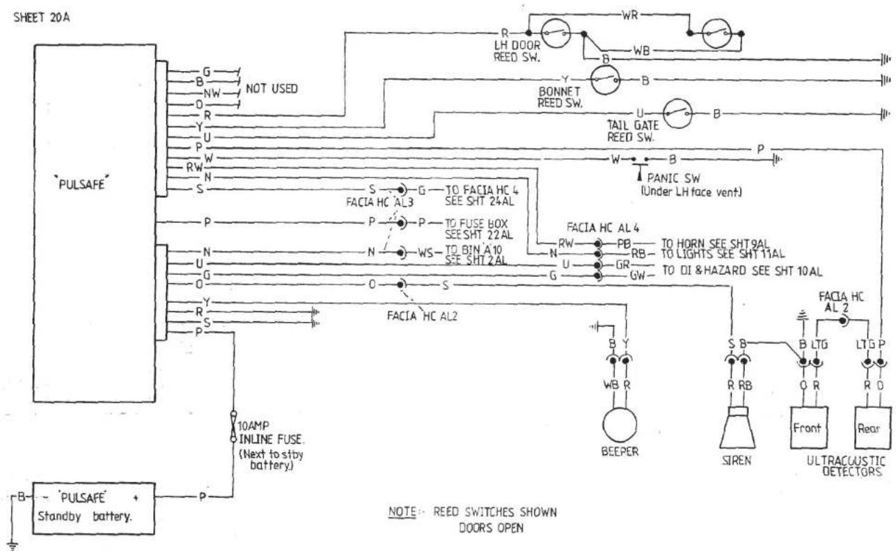
SECTION MC
PULSAFE ALARM
SHEET 20A


SHEET 20P
ULSAFE ALARM COMPONENT LOCATION

JHLLI 21

ENGINE BAY VENTILATION
SHEET 21
SECTION MC
SH

| NO. | FUSE RATING | CIRCUIT |
| 1 | 20A. | INTERIOR FANS |
| 2 | ||
| 3 | 5A. | L.H SIDE / TAIL/ NO. PLATE LAMPS |
| 4 | 15A. | HAZARD LAMPS / INTERIOR LAMP/CLOCK |
| 5 | 15A. | CIGAR LIGHTERS/ DOOR LAMPS |
| 6 | 10A. | RADIATOR FAN NO.1 |
| 7 | 10A. | DOOR MIRRORS / RADIO (AUX.) RADIO AMP (AUX.) [If fitted] |
| 8 | 5A. | INSTRUMENTS & WARNING LAMPS |
| 9 | 5A. | R.H. SIDE / TAIL/ LICENCE NO. PLATE LAMPS |
| 10 | 15A. | STOP LAMPS/SEAT BELT BUZ RADIO (Mem) RADIO AMP (If fitted) ANTENNA |
| 11 | 25A. | HEAD LAMP WASH |
| 12 | 10A. | RADIATOR FAN NO. 3 |
| 13 | 5A. | HEATED REAR SCREEN |
| 14 | 15A. | WIPER MOTOR/ SCREEN WASH |
| 15 | 5A. | HEAD LAMP MOTORS (DOWN CONTROL) |
| 16 | 10A. | HEAD LAMP MOTORS |
| 17 | 10A. | HORN / HEAD LAMP FLASH |
| 18 | 10A. | RADIATOR FAN NO. 2 |
| 19 | 10A. | REVERSE LAMPS |
| 20 | 10A. | INDICATORS |
| 21 | 10A. | A.C.U. COMPRESSOR / A.C.U.-RADIATOR FANS CONTROL |
| 22 | 10A. | ENGINE CONTROL (AUX.) |
| 23 | 10A. | ENGINE CONTROL (IGN.) |
| 24 | 10A | ALARM |

ELECTRONIC UNIT
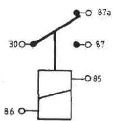

RELAY CONNECTIONS
SHEET 23
![graph TD A["SPLICE 'D' SEE SHT.1"] --> B["W"] B --> C["FUSE BOX B 8 A"] C --> D["G"] D --> E["BRAKE FAIL WARNING CIRCUIT SEE SHT.15"] C --> F["G"] F --> G["FACIA HC AL3"] G --> H["L.H. DI.W/LT SEE SHT.10"] H --> I["G"] I --> J["FACIA H.C"] J --> K["R.H. DI.W/LT SEE SHT.10"] K --> L["G"] L --> M["HAN…](/content/2026/05/1021120/images/28c003b0ff4025c22ff2968a50ca1107cb1715f80017e0b0011812c4746a7763.jpg)
SPLICE 'G'
SHEET 24
3712
![graph TD A["POSITIVE POST SEE SHT.1"] --> B["HEAD LAMP WASH SEE SHT.14"] A --> C["HEAD LAMP MOTORS SEE SHT.9"] A --> D["HORN & HEAD LAMP FLASH SEE SHT.9"] A --> E["STOP LAMPS SEE SHT.13"] A --> F["RADIO SEE SHT.20"] G["N"] --> H["HEAD LAMP WASH P A 11 B N"] G --> I["HEAD LAMP MOTORS P A 16 B N"] G -…](/content/2026/05/1021120/images/1041a15cccdad47e9980108d7a15f38bfb3e6645087b138f03fcf4e08e0d15e5.jpg)
SPLICE 'A'
SHEET 25

5
SHEE 5
![graph TD A["WINDOW LIFT SEE SHT. 18"] --> B["POWER RELAY (AUX.) SEE SHT.1"] A --> C["ENGINE MANAGEMENT SEE SHT. 3"] A --> D["BOOR MIRRORS SEE SHT. 19"] A --> E["RADIO SEE SHT. 20"] A --> F["INTERNAL FANS SEE SHT. 7"] B --> G["B 7 A"] C --> H["B 22 A"] D --> I["YG"] E --> J["YG"] F --> K["YG"] G -->…](/content/2026/05/1021120/images/831da8a2c5c697f59d57ec56a00f464571136a8c5ad955f1d94e043a0107fa37.jpg)
SPLICE 'B'
SHEET 26
![graph TD A["ENGINE MANAGEMENT SEE SHT.3"] --> B["G"] B --> C["A 23 B"] B --> D["W"] C --> E["B"] D --> F["W"] G["INDICATORS SEE SHT.10"] --> H["G"] H --> I["A 20 B"] H --> J["W"] K["REVERSE LAMPS SEE SHT.19"] --> L["G"] L --> M["A 19 B"] L --> N["W"] O["NOT USED"] --> P["G"] P --> Q["B"] Q --> R["W"…](/content/2026/05/1021120/images/b14aee2d302e5be26f742a2d3467b52654d02a0aa712b0e3a70a84fc7f32380b.jpg)

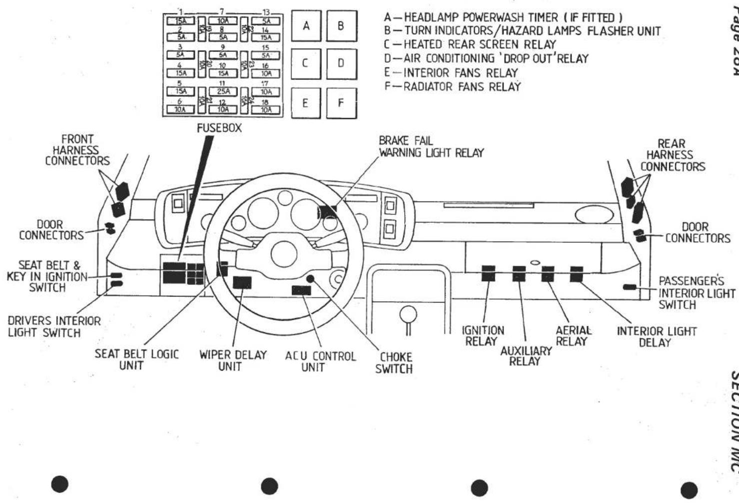
Page 28A
SECTION MC
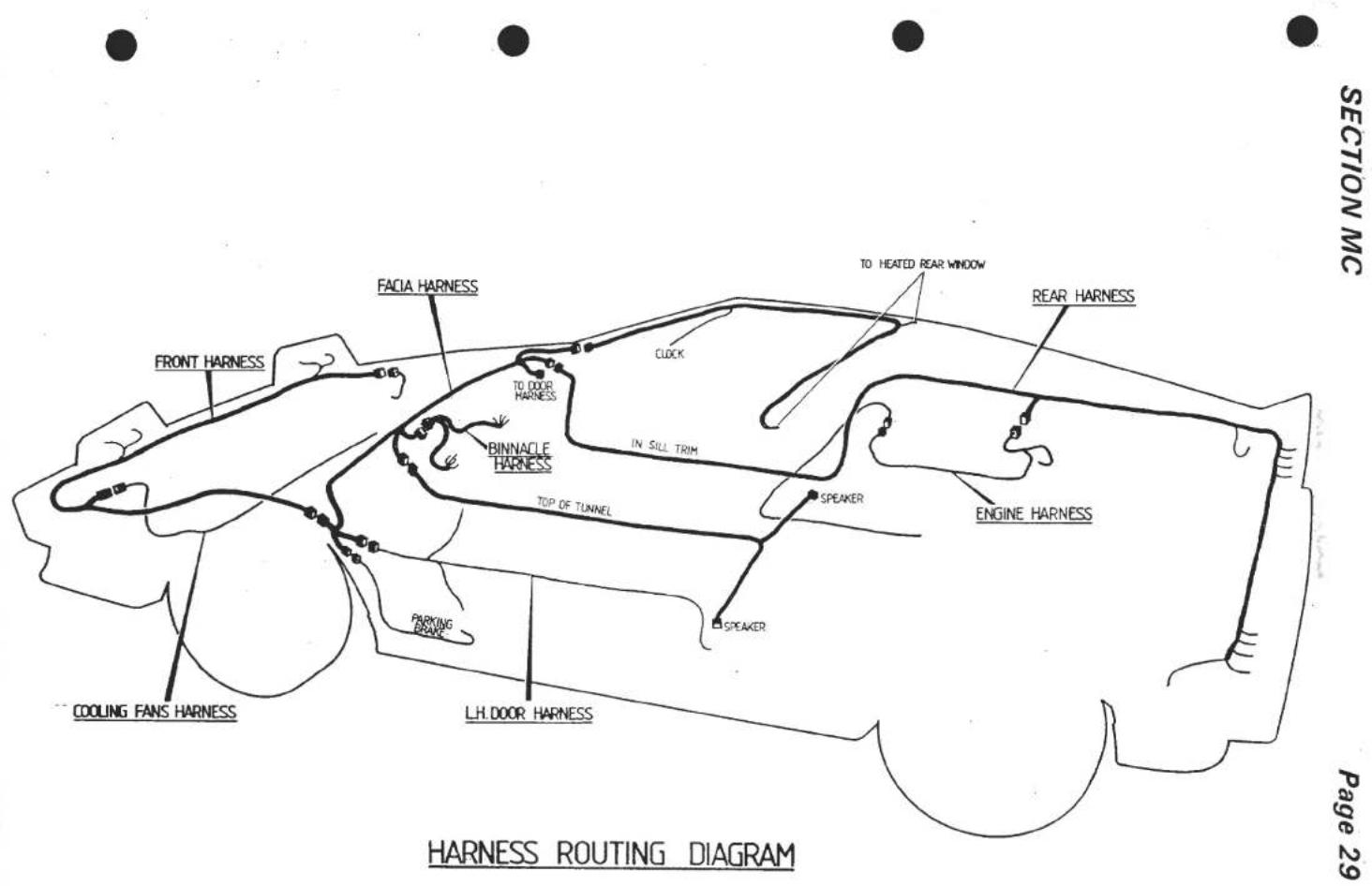
INSTRUMENT BINNACLE REMOVAL
The instrument binnacle contains a centre panel housing the main instruments, and two side panels housing the tell tale lamps, switches and volt and fuel gauges.
The side panels may be removed with the binnacle 'in situ' by removing the four screws securing the centre panel ABS trim, followed by the single screw securing each side panel at its outermost edge. Access to the fibre optic light source (switch illumination) may be obtained after removal of the right hand side panel. Voltmeter and fuel gauge illumination bulbs may also be replaced after removal of the appropriate side panel. The Brake fail warning lamp relay may also be reached after removal of the left hand side panel.
For access to an instrument housed in the centre panel, it is necessary first to remove the binnacle assembly from the fascia. After removal of the four M6 bolts securing the binnacle assembly to the scuttle crossbeam (accessible from beneath) the binnacle may be raised sufficiently to enable the three wiring loom block connectors to be unplugged, the speedo cable to be released, and the boost and oil pressure gauge pipes to be disconnected. Also release the demist vent duct from the binnacle adaptor.
LUCAS CONSTANT ENERGY IGNITION
The Lucas constant energy ignition system is an inductive system in which the energy stored in the coil is maintained constant over a wide range of engine speeds, thereby providing consistently high output voltages. The system comprises a distributor model 45 DM, and ignition coil model 32 C5, an ignition amplifier model AB 14 and an electronic rev. limiter.
The distributor incorporates a variable-reluctance position transducer (pick up) to provide a basic timing waveform. The sintered reluctor has four projections which correspond in function with the cam lobes of a conventional distributor. The pick up comprises a coil and magnet assembly, the pick up air gap (0.20 - 0.35 mm.) being set during manufacture and requiring no subsequent adjustment.
A conventional type rotor arm is fitted, moulded (as is the distributor cap) from track retardant material. The two cables connecting the distributor to the ignition amplifier terminate in a non-reversible "shur plug".
The high energy coil (model 32 C5) is specially designed to achieve the very fast current rise times required for this system. The coil requires no ballast and consumes no current in the stalled engine condition.
The ignition amplifier (AB 14) is mounted in the ignition box whilst the electronic rev. limiter unit is fitted on the RH fuel tank board.
The ignition must be switched on for the following checks.
Recommended Test Equipment
DC moving coil voltmeter, scale 0 - 20V
DC moving coil ohmmeter
HT jumper cable
| TEST | RESULT | |||
1 CHECK HT SPARKING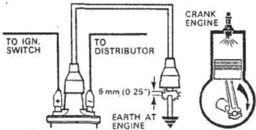 | Should be:Regular sparking———→TEST 6No sparking———→TEST 2 | |||
 | Measure voltages at 1-4 incl.should be:1-More than 11·5V2-1V max. below V at 13-1V max. below V at 14-0V-0·1VAll correct———→TEST 3incorrect reading(s)———→SEE CHART | |||
| 1 | 2 | 3 | 4 | SUSPECT |
| LOW | √ | √ | √ | Battery discharged |
| √ | LOW | LOW | √ | Ignition switch and/or wiring |
| √ | √ | LOW | √ | Coil or amplifier |
| √ | √ | √ | HIGH | Amplifier earth (ground) |
3 CHECK AMPLIFIER SWITCHING | Voltage increaseswhile cranking———→TEST 5Voltage does not increasewhile cranking———→TEST 4 | |||
4 PICK-UP COIL RESISTANCE | Ohmmeter should show2-5 kΩCorrectChange amplifierIf engine will not start  IncorrectChange pick-upIf engine will not start IncorrectChange pick-upIf engine will not start  | |||
5 CHECK HT SPARKING[CT7XY]  | Should be good HT sparkingRepeat with original HT leadGood sparkingIf engine will not s:  TEST 6No sparking, replace HT leadIf engine will not s: TEST 6No sparking, replace HT leadIf engine will not s:  TEST 6No sparkingReplace coilIf engine will not start TEST 6No sparkingReplace coilIf engine will not start  TEST 6 TEST 6 | |||
6 CHECK ROTOR ARM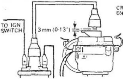  | Should be:No sparking ——  TEST 7 TEST 7 HT sparkingReplace rotor arm/rotor vaneIf engine will not start HT sparkingReplace rotor arm/rotor vaneIf engine will not start  [TEST] [TEST] | |||
| 7 VISUAL AND HT CABLE CHECKSEXAMINE1 Distributor Cover2 Coil Top3 H.T. Cable Insulation4 H.T. Cable Continuity5 Spark Plugs | Should be:1 Clean, dry, no tracking marks2 Clean, dry, no tracking marks3 Must not be cracked, chated or perished4 Must not be open circuit5 Clean, dry, and set to correct gap | |||
Note: If a fault is diagnosed with the distributor pick up assembly, the complete distributor must be replaced as without the specialist equipment required for correct adjustment, extensive engine damage could result from any attempt to replace internal components.
BATTERY RE-CHARGING PROCEDURE
Instructions for Tungstone Powermaster Maintenance Free Batteries.
To determine the state of charge of the battery, apply a brief discharge of no more than ten seconds duration (e.g. turn on headlights) with the engine off, and then allow to stand on open circuit for two to three minutes.
Measure the terminal voltage of the battery.
If steady voltage is below 12.4 Volts, recharge battery as follows.
Note: The battery must not be boost charged.
If necessary, fit a replacement battery to the vehicle, whilst original battery is charged as follows.
Remove battery from vehicle.
a). Constant Current: The battery must be charged at a maximum of 5 amps until the battery terminal voltage (on charge) has stabilised over a one hour period, at which time the voltage will be in the range 16.0 - 16.5 V. At this stage the battery must be taken off charge IMMEDIATELY, to prevent excess gassing with resulting water loss which will ultimately reduce the guaranteed service life.
b). Constant Voltage: The battery may be charged at a voltage up to a maximum of 15.8V providing the current is carefully monitored and the charge terminated when the current has tapered off and changes by less than 0.1 amp over a period of one hour. If it is not possible to monitor the current during charging, then the voltage must be restricted to 14.4 V maximum.

Battery access
ELECTRICAL
SECTION ME - USA ESPRIT TURBO, '86 M.Y. ON (H.C.I.)
Sheet/Page
| Circuit Diagrams: | |
| Component Index | - |
| Legend | - |
| Supplies | 1 |
| Start, Alternator, Ignition | 2 |
| Fuel Injection Management System | 3A/B |
| Fuel Pumps | 3C |
| Fuel Level | 4 |
| Radiator Cooling Fans | 5 |
| Air Conditioning | 6 |
| Internal Fans | 7 |
| Headlamp Beam, Dip, Flash | 8 |
| Horns, Beam, Dip and Column Switch Supply | 9A |
| Headlamp Motor Operation | 9B/C/D/E/F |
| Direction Indicators & Hazard | 10 |
| Rear Lights, Instrument Illumination | 11 |
| Clock, Door Lamps, Interior Lamps, Cigar Lighter | 12 |
| Stop Lights, Reverse Lights | 13 |
| Wipers & Washer | 14 |
| Brake Fail & Handbrake Warning | 15 |
| Seat Belt Logic, Water & Battery Gauge | 16 |
| Heated Rear Screen | 17 |
| Window Lift | 18 |
| Mirrors | 19 |
| Radio & Radio Amp (if fitted) | 20 |
| Low oil and coolant warning | 21 |
| Fuse box, Circuits and Ratings | 22 |
| Relay Connections | 23 |
| Splice 'G' | 24 |
| Splice 'A' | 25 |
| Splice 'B' | 26 |
| Splice 'D' | 27 |
| Component Location Diagram | 28 |
| Harness Routing Diagram | 29 |
| Instrument Binnacle Removal | 30 |
| Lucas 'Constant Energy' Ignition | See Section MC |
COMPONENT INDEX
Sheet / Page
A.C.U. Compressor 6
A.C.U. Tem. Control 5
A.C.U. Thermistor 5
Alternator 2
Auxiliary Air Valve 3B
Battery 2
Cigar Lighters 12
Clock 12
Cold Start Injector 3B
Compressor, air horns 9
Distributor 2
Electronic Control Unit (ECU) 3B
Engine, Overspeed/Fuel Pump failure 3C
Frequency Valve 3B
Fuel Enrichment module 3A
Fuel Sender Unit 4
Fuse Box 22
Heated Rear Screen 17
Ignition Amplifier 2
Ignition Coil 2
Intermittent Wipe Unit 14
Instruments - Battery Condition 16
- Fuel Gauge 4
- Tachometer 2
- Temp Gauge 16
Lambda Sensor 3B
Lights - Brake Fail Warning 15
- Door Warning 12
- D.I. & Hazard Lamps 10
- Economy Warning 3A
- Fan Fail Warning 5
- Handbrake Warning 15
- Headlamps 8
- Ignition Warning 2
- Instrument Illumination 11
- Interior Lamp 12
- Low Fuel Warning 4
- Low Coolant Warning 21
- Licence Plate Lamps 11
- Panel Lights 1 12
- Reverse Lamps 13
- Seat Belt Warning 16
- Side Market, Front 10
- Side Marker, Rear 11
-Stoplamps 13
- Tailamps 11
Mirrors 19
Motors - Antenna 20
- Internal Fans 7
- Mirrors 19
- Radiator Cooling Fans 5
- Window Lift 18
- Windscreen Wiper 14
Pumps - Fuel 3C
- Screen Wash 14
Radio 20
SECTION ME
Sheet/Pag
Radio Amp. (if fitted) 20
Relays - ACU Control 6
- Brake Fail 15
- Dip Beam 8
- D.I. & Hazard Unit 10
- Engine Management 3A
- Flash 8
- Fuel Pump Control 3C
- Headlamp Motors 9
- Heated Rear Screen 17
- Horn 9
- Internal Fans 7
- Lamp Delay Unit 12
- Main Beam 8
- Power (aux.) 1
- Power (ign) 1
- Radiator Cooling Fans 5
Rheostats 11
Solenoids - Starter 2
Speakers 20
Switches - Door 12
- Door Mirror c/o 19
- Door Mirror Control 19
- Column, Dip/Beam 8
- Handbrake 15
- Hazard 10
- Heated Rear Screen 17
- Ignition 2
- Inertia 3C
- Internal Fans, speed 7
- Lights 8
- Low Brake Fluid 15
- Low Pressure Cut Out (ACU) 5
- Low Vacuum (brakes) 15
- Oil Temperature 3B
- Overboost 3C
- Reverse Light 13
- Seat Belt 16
- Stop Light 13
- Thermal (engine management) 3B
- Throttle position 3B
- Window Lift 18
- Temp Transmitter 16
- Voltage Stabiliser 4,16
- Water Temperature 3B
- Warm Up Regulator 3B
SECTION ME
LEGEND
| BIN | Binnacle Connector |
| D.H.C. | Door Harness Connector |
| D.I. | Direction Indicator |
| E.B.C. | Engine Bulkhead Connector |
| E.H.C. | Engine Harness Connector |
| F.H.C. | Front Harness Connector |
| L.H. | Left Hand |
| P.H.C. | Pumps Harness Connector |
| R.H. | Right Hand |
| R.H.C. | Rear Harness Connector |
| SOL | Solenoid |
| S/W | Switch |
| W/LT. | Warning Light |
| C.C.C. | Centre Console Connector |
| M.H.C. | Manifold Harness Connector |
| C.F.H.C. | Cooling Fans Harness Connector |
| C.B.H.C. | Coil Box Harness Connector |
Cable Colour Code
| B | Black | O | Orange |
| G | Green | R | Red |
| K | Pink | S | Slate |
| P | Purple | U | Blue |
| LTG | Light Green | W | White |
| N | Brown | Y | Yellow |
SHEET 1
![graph TD A["HEAD LAMP"] --> B["NU"] B --> C["9"] C --> D["NU"] D --> E["FHC"] E --> F["NU"] F --> G["4"] G --> H["NU"] H --> I["TO RAD. FAN"] I --> J["RELAY SEE SHT 5"] J --> K["N"] K --> L["POSITIVE POST"] L --> M["N"] M --> N["SPLICE 'A' SEE SHT 25"] L --> O["NR"] O --> P["2"] P --> Q["NR"] Q -->…](/content/2026/05/1021120/images/b73c48c387820dc40cc6fbbe81f8bc75540a8e1b8dd8ccb9225956d744b47c23.jpg)
SECTION ME


SUPPLIES


START, ALTERNATOR & IGNITION
SHEET 2

![graph TD A["LECHTRONIC CONTROL UNIT"] --> B["SCREENED CABLE"] B --> C["SENSOR HEATING COIL"] C --> D["LAMBOA SENSOR"] D --> E["THROTTLE POSITION SWITCH"] E --> F["OIL TEMP SWITCH"] E --> G["AUXILIARY AIR VALVE"] E --> H["WARM UP REGULATOR"] H --> I["FREQUENCY VALVE"] H --> J["COLD START INJECTION"]…](/content/2026/05/1021120/images/623665456e2ce1c4e6a16929ae284a529fe9808e09728ba899b6cb76da07a78d.jpg)
FUEL INJECTION MANAGEMENT SYSTEM
SHEET 3B
SHEET 3C


FUEL LEVEL
SHEET 4


AIR CONDITIONING
SECTION ME
SHEET 6
SHEET 7

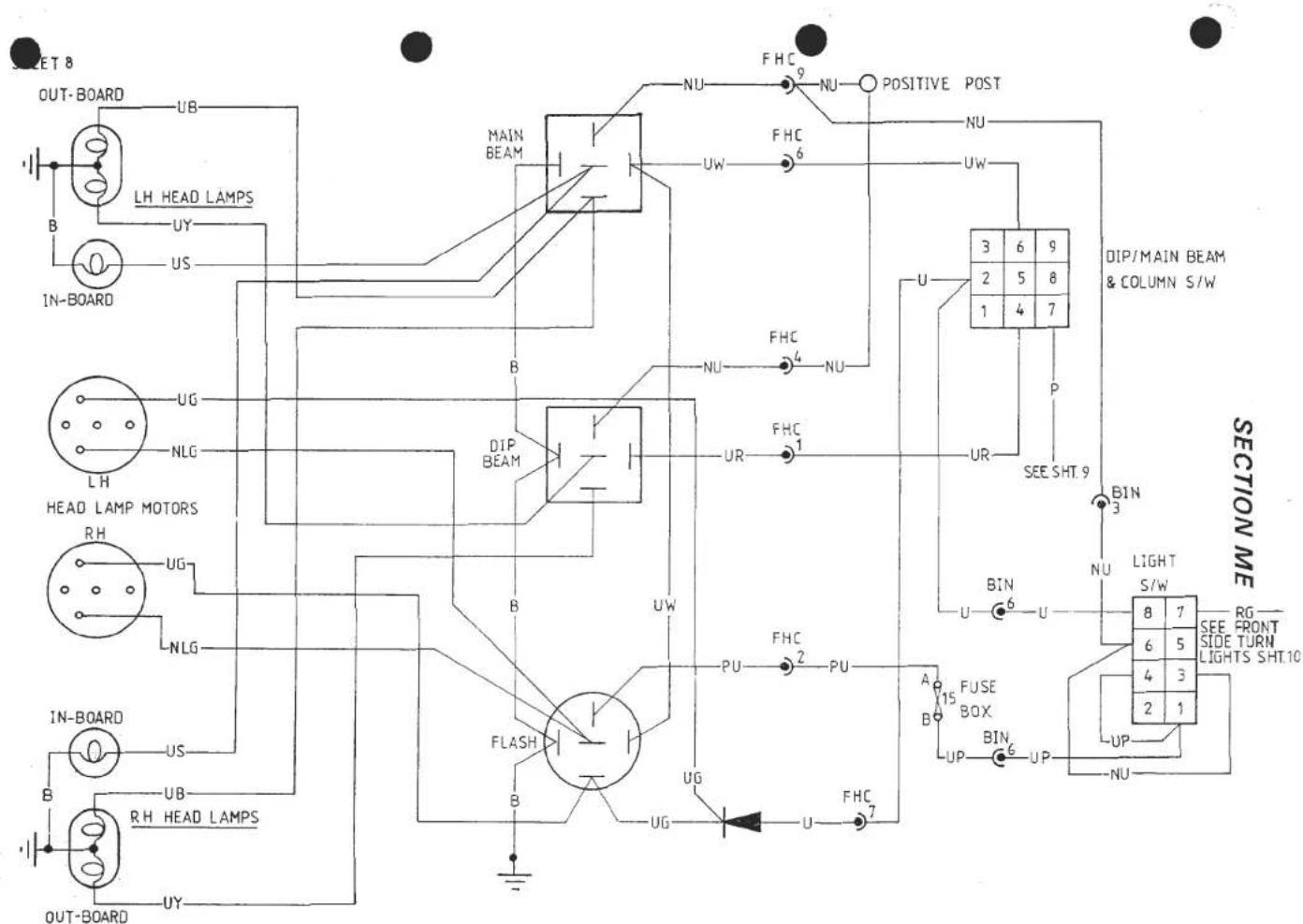
HEAD LAMP MAIN BEAM, DIP BEAM & FLASH
SHEET 8
SHEET 9A
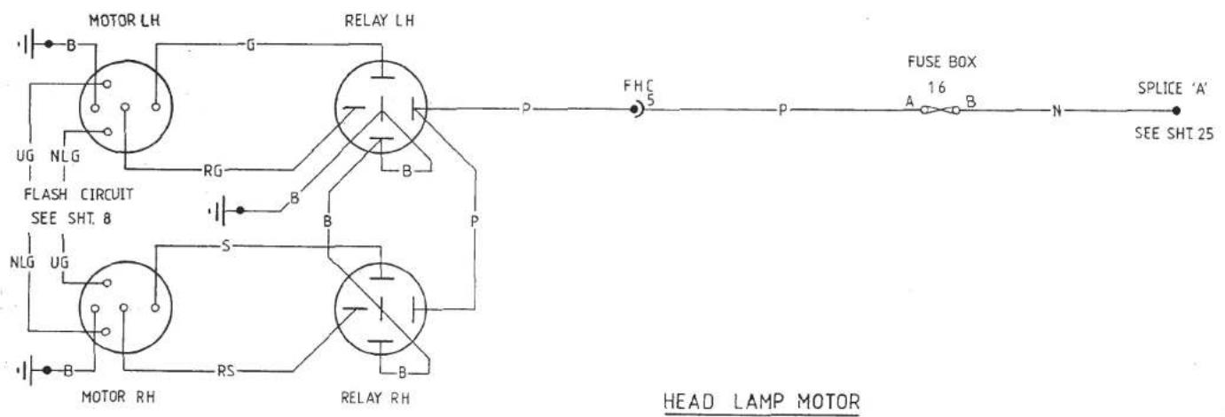

![graph TD A["RH HEADLAMP MOTOR"] --> B["Down MICRO-SWITCH"] B --> C["UP MICRO-SWITCH"] C --> D["RG"] D --> E["RH MOTOR RELAY"] E --> F["B"] F --> G["P"] G --> H["NLG"] H --> I["P"] I --> J["10A N"] J --> K["POSITIVE POST"] K --> L["HEAD LAMP MOTOR OPERATION"] M["LH HEADLAMP MOTOR"] --> N["Down MICRO-…](/content/2026/05/1021120/images/329739e423f070961740c8a78ff315945dbd43527a418a1a59687f0a40705583.jpg)
HEAD LAMP MOTOR CIRCUIT
SHEET9B
![graph TD A["R/H HEADLAMP MOTOR"] --> B["RLS"] B --> C["R.H.MOTOR RELAY"] C --> D["NLG"] D --> E["P"] E --> F["POSITIVE POST"] F --> G["10A N"] G --> H["PODS TRAVELLING UP"] I["LH HEADLAMP MOTOR"] --> J["RS"] J --> K["LH.MOTOR RELAY"] K --> L["S"] L --> M["UG"] M --> N["NLG"] N --> O["UG"] O --> P["P…](/content/2026/05/1021120/images/430de4de740f397c0bbe40b152581bc545c1e05a4a40e56b75f2280cf3c59cc5.jpg)
![graph TD A["RH HEADLAMP MOTOR"] --> B["RG"] B --> C["RH MOTOR RELAY"] C --> D["P"] D --> E["NLG"] E --> F["POSITIVE POST"] F --> G["10A N"] G --> H["PODS UP"] I["LH HEADLAMP MOTOR"] --> J["RS"] J --> K["LH MOTOR RELAY"] K --> L["S"] L --> M["UG"] M --> N["UG"] N --> O["NLG"] O --> P["FLASH RELAY"] P…](/content/2026/05/1021120/images/601503b107526d7269281beae1e7e11e45feefcb16755ceaeb9d898651fafd00.jpg)
HEAD LAMP MOTOR CIRCUIT
SHEET 90
![graph TD A["RH HEADLAMP MOTOR"] --> B["RG"] B --> C["RH MOTOR RELAY"] C --> D["NLG"] D --> E["POSITIVE POST"] E --> F["10A"] F --> G["N"] G --> H["10A"] H --> I["PODS TRAVELLING DOWN"] J["LH HEADLAMP MOTOR"] --> K["RG"] K --> L["LH MOTOR RELAY"] L --> M["S"] M --> N["UG"] N --> O["FLASH RELAY"] O --…](/content/2026/05/1021120/images/ea93bb98cd83991981dd88301caff107fee73b08ebbcb500e212dceabcd3ac07.jpg)
![graph TD A["RH HEADLAMP MOTOR"] --> B["RLG"] B --> C["RH MOTOR RELAY"] C --> D["FLASH RELAY"] D --> E["UG"] E --> F["UP"] F --> G["LUW"] G --> H["TO MAIN BEAM RELAY COIL"] H --> I["FLASHER/DIPSWITCH"] I --> J["UG"] J --> K["UP"] K --> L["LUW"] L --> M["TO DIP BEAM RELAY COIL"] M --> N["UP"] N --> O[…](/content/2026/05/1021120/images/7f6790d2d367cafdfc68053a24ed9e21964dde8fdc4bc88e1009cdba2cc4d545.jpg)
HEAD LAMP MOTOR CIRCUIT
SHEET 9F
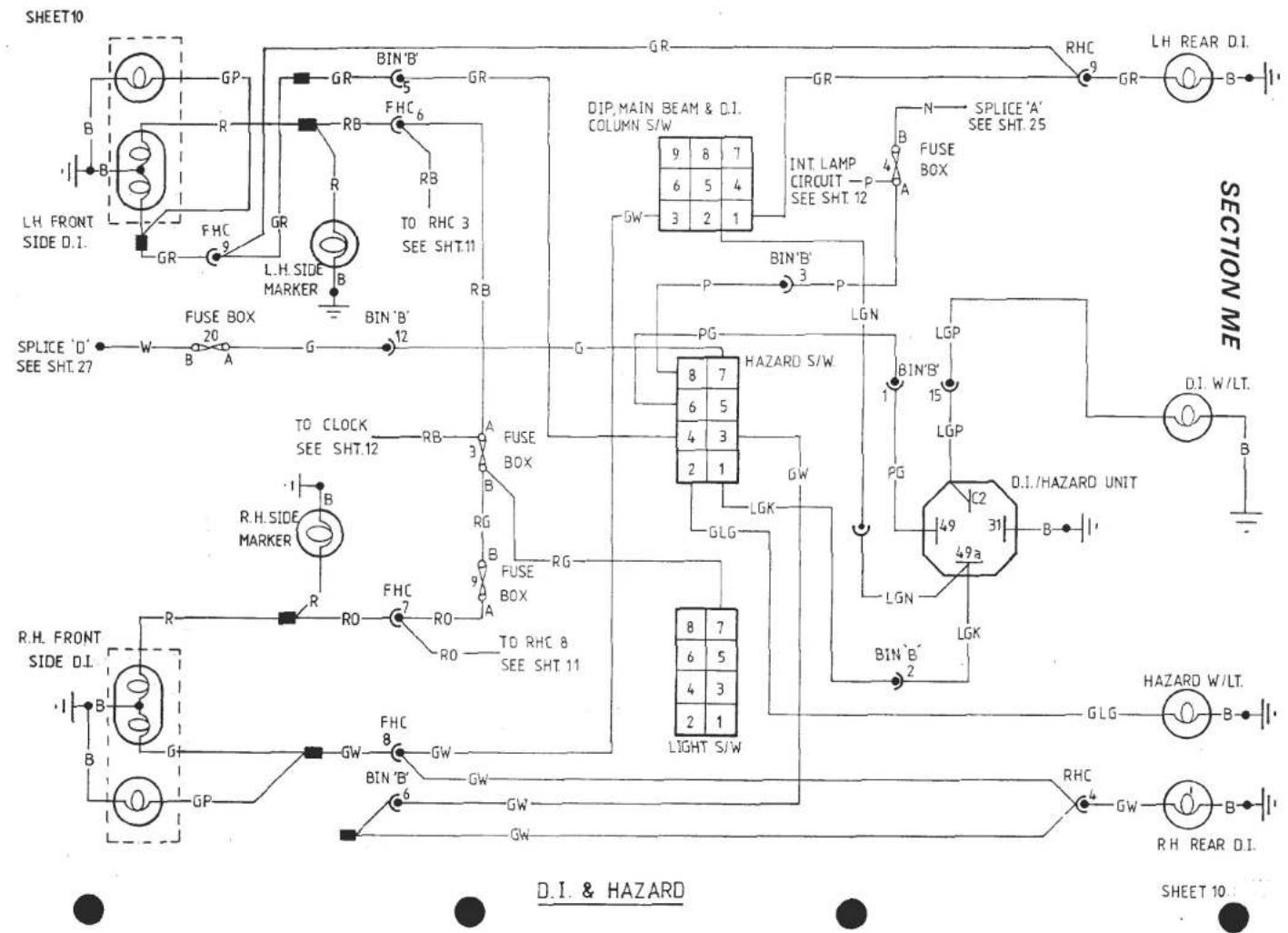
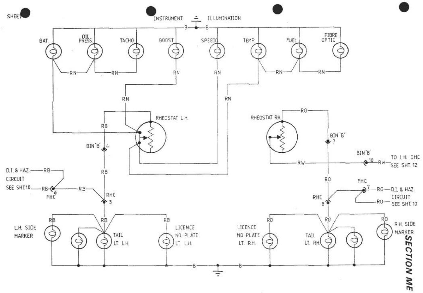
REAR LIGHTS & INSTRUMENT ILLUMINATION
SHEET 11

CLOCK, DOOR WARNING & INTERNAL LAMPS
SHEET 12

REVERSE LIGHT
SHEET13

WIPERS
SHEET 14

MIRRORS (Movement by motors)
SHEET:19
SHEET 20

RADIO & RADIO AMP (If fitted)
SHEET 20

![graph TD A["LOW OIL W/Lt"] --> B["Low COOLANT W/Lt"] C["SPLICE 'B' SEE SHT.26"] --> D["G"] E["MIN 'B'"] --> F["14"] G["BIN 'B'"] --> H["SO"] I["SG"] --> J["EHC"] K["RHC"] --> L["5"] M["B"] --> N["SG"] O["YG"] --> P["SG"] Q["RG"] --> R["SG"] S["LGB"] --> T["SG"] U["G"] --> V["SG"] W["B"] --> X["SG"]…](/content/2026/05/1021120/images/91665065c916fad25bb50d7e05ab6e189ecee48d5ce402307ecc97e3944e7642.jpg)
LOW OIL & COOLANT WARNING
SECTION ME
SHEET 22
| NO. | FUSE RATING | CIRCUIT |
| 1 | 15A. | INTERIOR FANS |
| 2 | ||
| 3 | 5A. | L.H. SIDE / TAIL/ NO. PLATE LAMPS |
| 4 | 15A. | HAZARD LAMPS / INTERIOR LAMP / CLOCK |
| 5 | 15A. | CIGAR LIGHTERS / DOOR LAMPS |
| 6 | 10A. | RADIATOR FAN NO.1 |
| 7 | 10A. | DOOR MIRRORS / RADIO (AUX.) RADIO AMP (AUX.) (If fitted) |
| 8 | 5A. | INSTRUMENTS & WARNING LAMPS |
| 9 | 5A. | R.H. SIDE / TAIL/ LICENCE NO. PLATE LAMPS |
| 10 | 15A. | STOP LAMPS/ SEAT BELT BUZ RADIO (Mem.) RADIO AMP (If fitted) ANTENNA |
| 11 | ||
| 12 | 10A. | RADIATOR FAN NO. 3 |
| 13 | 5A. | HEATED REAR SCREEN |
| 14 | 15A. | WIPER MOTOR / SCREEN WASH |
| 15 | 5A. | HEAD LAMP MOTORS (DOWN CONTROL) |
| 16 | 10A. | HEAD LAMP MOTORS |
| 17 | 10A. | HEAD LAMP FLASH (early cars 20A to include horn - no line fuse) |
| 18 | 10A. | RADIATOR FAN NO. 2 |
| 19 | 10A. | REVERSE LAMPS |
| 20 | 10A. | INDICATORS |
| 21 | 10A. | A.C.U. COMPRESSOR / A.C.U.-CONTROL |
| 22 | 10A. | ENGINE CONTROL (AUX.) |
| 23 | 10A. | ENGINE CONTROL (IGN.) |
| 24 | 5A | RADIATOR FANS CONTROL |

ELECTRONIC UNIT
RELAY CONNECTIONS
SHEET 24
![graph TD A["SPLICE 'D' SEE SHT.1"] --> B["FUSE BOX B B A"] B --> C["FACIA H.C"] C --> D["R.H. D.I. W/LT. SEE SHT.10"] C --> E["G"] E --> F["H.R.S. S/W SEE SHT.17"] E --> G["TACHO SEE SHT.2"] E --> H["IGN. W/LT. SEE SHT.2"] C --> I["G"] I --> J["SEAT BELT W/LT. SEE SHT.16"] C --> K["G"] K --> L["BATT…](/content/2026/05/1021120/images/45fd7a60312a4cacc318a369d942c42c7498884e28b4ef1ec8815318121feb2f.jpg)
SECTION ME
SPLICE 'G'
SHEET 24

![graph TD A["HEAD LAMP MOTORS SEE SHT. 9"] --> B["N"] A --> C["A 16 B"] A --> D["B N"] A --> E["N"] F["HEAD LAMP FLASH SEE SHT. 9"] --> G["P"] F --> H["A 7 B"] F --> I["B N"] F --> J["N"] K["SPLICE 'A'"] --> L["STOP LAMPS SEE SHT. 13"] K --> M["RADIO SEE SHT. 20"] K --> N["A 10"] K --> O["B"] P["POSI…](/content/2026/05/1021120/images/4b78c4d95c01f813b9c8fb9959932c27cebc0c637447c6488ee62acd8cfc0494.jpg)
SHEET 26
![graph TD A["WINDOW LIFT SEE SHT. 18"] --> B["POWER RELAY (AUX.) SEE SHT.1"] A --> C["AO 1"] A --> D["INTERNAL FANS SEE SHT.7"] A --> E["FUEL INJECTION MANAGEMENT SYSTEM SEE SHT. 3A"] B --> F["DOOR MIRRORS SEE SHT. 19"] B --> G["RADIO SEE SHT. 20"] C --> H["BO Box 7 A"] C --> I["BO Box 22 A"] D --> J…](/content/2026/05/1021120/images/b23bce850a574c94cef971fd6d4ac4843a3a7534253f20b3b33d8340a9713c5c.jpg)
![graph TD A["POWER RELAY (IGN)\nSEE SHT. 1"] --> B["FUEL INJECTION MANAGEMENT SYSTEM\nSEE SHT. 3A"] A --> C["INDICATORS\nSEE SHT. 10"] A --> D["REVERSE LAMPS\nSEE SHT. 19"] A --> E["NOT USED"] B --> F["A 23 B W"] C --> G["A 20 B W"] D --> H["A 19 B W"] E --> I["B 14 A"] F --> J["RHC 5 W"] G --> K["B…](/content/2026/05/1021120/images/4ce165df833ac2e5ba2b7faddc20886cef4b1fcc8e3a37a3cc720c005ebc8d80.jpg)


COMPONENT LOCATION DIAGRAM (2)

Page 29
INSTRUMENT BINNACLE REMOVAL
The instrument binnacle contains a centre panel housing the main instruments, and two side panels housing the tell tale lamps, switches and volt and fuel gauges.
The side panels may be removed with the binnacle 'in situ' by removing the four screws securing the centre panel ABS trim, followed by the single screw securing each side panel at its outermost edge. Access to the fibre optic light source (switch illumination) may be obtained after removal of the right hand side panel. Voltmeter and fuel gauge illumination bulbs may also be replaced after removal of the appropriate side panel. The Brake fail warning lamp relay may also be reached after removal of the left hand side panel.
For access to an instrument housed in the centre panel, it is necessary first to remove the binnacle assembly from the fascia. After removal of the four M6 bolts securing the binnacle assembly to the scuttle crossbeam (accessible from beneath) the binnacle may be raised sufficiently to enable the three wiring loom block connectors to be unplugged, the speedo cable to be released, and the boost and oil pressure gauge pipes to be disconnected. Also release the demist vent duct from the binnacle adaptor.
| Page | |
| Recommended Lubricants | 2 |
| Bodywork Defects Sample Sheet | 3/4 |
| Pre-Delivery Inspection Sample Worksheet | 5/6 |
| First After Sales Service Sample Worksheet | 7 |
| Maintenance Plan Sample Worksheet | 9/10 |
RECOMMENDED LUBRICANTS
ENGINE:
Lotus Cars Ltd. strongly recommend that the following engine lubricants are used at oil changes, and where possible/practical between services.
| Above 0°C | Valvoline HP Racing | SAE 20W/50 |
| Elf Competition | SAE 20W/50 | |
| Mobil 1 Rally Formula | SAE 5W/50 |
| Below 0°C | Valvoline XLD | SAE 15W/40 |
| Elf Sporti | SAE 15W/40 | |
| Mobil 1 Rally Formula | SAE 5W/50 |
In severe winter conditions below -15°C a SAE 10W/40 Oil or Mobil 1 Rally Formula SAE 5W/50 is recommended.
When recommended products are unobtainable, engine lubricants meeting the following specifications may be used.
| VISCOSITY | PERFORMANCE | |
| Above 0°C | SAE 20W/50 | API Service SF |
| Below 0°C | SAE 15W/40 | API Service SF |
| Below -15°C | SAE 10W/40 | API Service SF |
TRANSMISSION FRONT HUBS
STEERING SWIVELS (Prior '85 MY) BRAKE & CLUTCH HYDRAULICS
SAE 80
Lithium base wheel bearing grease
SAE 90
-
API GL5
NLGI No.2
API GL5
DOT 3 or DOT 4


Bodywork Defects Sheet


| DEFECT CODE | |
| A | SCRATCHES |
| B | OVERSPRAY |
| C | DIRT UNDER PAINT |
| D | RUN |
| E | SINKAGE |
| F | THIN PAINT |
| G | GEL CRAZING |
| H | CHIPS |
| J | PIN HOLES |
| K | FLAKING |

| UNIT No. |
| COLOUR |
| OWNER |
APR 1987

Bodywork Defects Sheet

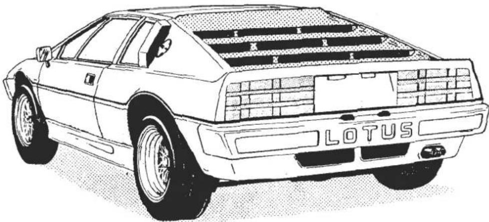
| DEFECT CODE | |
| A | SCRATCHES |
| B | OVERSPRAY |
| C | DIRT UNDER PAINT |
| D | RUN |
| E | SINKAGE |
| F | THIN PAINT |
| G | GEL CRAZING |
| H | CHIPS |
| J | PIN HOLES |
| K | FLAKING |
| UNIT No. |
| COLOUR |
| OWNER |
APR 1987
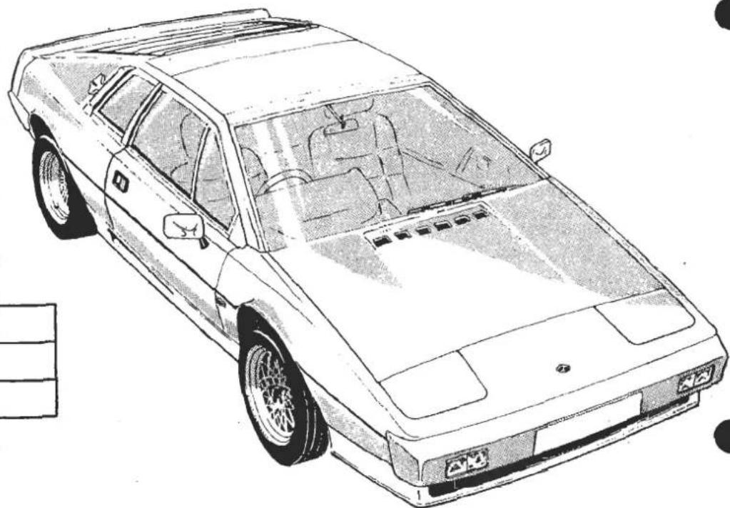
PRE-DELIVERY INSPECTION - ALL MODELS

MODEL
VIN: ENGINE NO.
| OPERATIONS - Tick box if O.K. - X box if additional work reqd. - submit defect report | OPERATOR INITIALS |
MECHANICAL
| Check coolant level and check system for leaks. | ||
| Renew engine oil and filter (Federal only) | ||
| Check engine, gearbox and rear axle oil levels and check for leaks. | ||
| Check security of engine oil filter. | ||
| Check brake/clutch fluid reservoir level. | ||
| Check fuel system for leaks. | ||
| Completely fill fuel tanks and check for leaks. | ||
| Check clutch adjustment. | ||
| Check tightness of wheel nuts/bolts. | ||
| Check tyre pressure including spare. | ||
| Check engine idling speed. | ||
| Check power assisted steering fluid level and system for leaks (when fitted). | ||
| Check automatic transmission fluid level (when fitted). |
ELECTRICAL
| Check security of battery terminals. | ||
| Check operation of all lamps. | ||
| Check operation of horns and direction indicators. | ||
| Check operation and park position of screen wipers. | ||
| Check operation of windscreen washers. | ||
| Check operation of all instruments. | ||
| Check operation of headlamps and door windows. | ||
| Check operation of heater and fan. | ||
| Check headlamp alignment. | ||
| Check operation of air conditioning equipment (when fitted). |
BODY
| Check operation of doors and locks. | ||
| Check bonnet and tailgate release mechanism. | ||
| Check interior trim for damage and cleanliness. | ||
| Check operation of seat belts. | ||
| Check all bright work and paint for condition. | ||
| Check presence of tool kit and literature pack. |
Road Test
Carry out brief road test and submit report with any additional attention required. Submit a defect report where necessary.
The pre-delivery inspection is subject to the following conditions:
(a) It is the responsibility of the supplying Distributor/importer/dealer to ensure that the car is delivered to the customer in the best possible condition.
(b) All costs incurred during the inspection are the responsibility of the supplying distributor/importer/dealer.
(c) Failure to return a signed copy of this inspection to Lotus Cars Limited by the distributor/importer/dealer, may result in warranty claims on the particular car being rejected.
DATE: DEALERS STAMP AND SIGNATURE:

First After Sales Service
LSL 246B
(NOT U.S.A.)
excel —— esprit S3 —— esprit turbo
Owner's name .... Date ....
Registration No. ....Job no. ....
V.I.N. Mileage
Mark as follows:
Adjustments made
OK.
Repairs desirable
(See separate sheet)
区
√
R
To be carried out at:
500-1000 miles
(800-1600 km)
MAINTENANCE NOTES:
"Inspect" means check for correct operation or condition — if wrong, advise before carrying out repairs or adjustments at extra time.
"Check" means test and adjust/fill or tighten as necessary.
| excel | esprit | |
| ● | ● | □ Install protective covers |
| ● | ● | □ Renew engine oil and filter, ensuring filter seals fully |
| ● | ● | □ Renew manual gearbox/transaxle oil |
| ● | □ Check auto transmission fluid level | |
| ● | □ Renew final drive oil | |
| ● | □ Lubricate propeller shaft universal joints | |
| ● | □ Lubricate lower steering swivels (if applicable) | |
| ● | ● | □ Lubricate throttle linkage and controls |
| ● | ● | □ Lubricate door locks and bonnet catches |
| ● | ● | □ Lubricate headlamp pod pivots |
| ● | ● | □ Check camshaft toothed belt tension and inspect valve timing |
| ● | ● | □ Check ignition timing and advance operation |
| ● | ● | □ Check all V-belt tensions |
| ● | ● | □ Check security of all fixings, especially engine mounting bolts, exhaust manifold and system, and inlet manifold and carburettor mountings |
| ● | ● | □ Check and adjust idle speed and CO level |
| ● | □ Check security and cleanliness of ignition harness joints including alternator and starter motor connections | |
| ● | ● | □ Top up cooling system and check security of all water hose connections |
| ● | ● | □ Inspect fuel system for leaks and check fuel pipe connections on carburettors |
| ● | ● | □ Inspect foot brake system for leaks and correct operation |
| ● | ● | □ Check handbrake adjustment and operation |
| ● | ● | □ Inspect all brake pipes and vacuum pipes and connections for damage, chafing, or leaks |
| ● | ● | □ Check brake, clutch and P.A.S. fluid reservoir levels |
| ● | ● | □ Inspect operation of brake fail/handbrake warning lamp |
| excel | esprit | |
| ● | ● | □ Check clutch operation and adjust if necessary |
| ● | ● | □ Check security of front and rear suspension, and steering column and steering rack assembly |
| ● | ● | □ Check front wheel alignment |
| ● | □ Inspect rear wheel toe-in | |
| ● | □ Check security of propshaft bolts | |
| ● | ● | □ Check front hub bearing adjustment |
| ● | ● | □ Inspect operation of all electrical equipment |
| ● | ● | □ Check battery electrolyte level, security of terminals and main earth connections |
| ● | ● | □ Check headlamp alignment |
| ● | ● | □ Inspect all tyres for damage, and set tyre pressures |
| ● | ● | □ Tighten all wheel nuts to specified torque loading |
| ● | ● | □ Check body condition generally, including door adjustments, bonnet and tailgate/boot adjustment (opening and closing), operation of door locks and tailgate/boot lock |
| ● | ● | □ Inspect seat adjustment mechanism and operation of seat belts |
| ● | ● | □ Inspect operation of heater/air conditioning and controls |
| ● | ● | □ Check final drive, gearbox and drive shaft mounting bolts to specified torque loadings |
| ● | ● | □ Ensure upholstery and driving controls are clean |
| ● | ● | □ Top up screen washer reservoir |
Work completed by.
Road Test Performance
| Engine performance |
| Clutch operation |
| Carbox operation/noise |
| Drive line noise/vibration |
| □ | Suspension noises | □ |
| □ | Brake performance | □ |
| □ | Wheel balance | □ |
| □ | Steering performance | □ |
| Turbo boost pressure | □ |
| Light operation | □ |
Work completed by ....

LSL 245B
Maintenance Plan (Not USA)
excel —— esprit S3 —— esprit turbo
Registration No. ....Job no. ....
V.I.N. Mileage
| Mark as follows: | Please tick Service required. | ||
| Adjustments made | ☒ | A — | ☐ |
| O.K. | ☑ | B — | ☐ |
| Repairs desirable(See separate sheet) | ☒ | C — | ☐ |
| For intervals see overleaf | |||
MAINTENANCE NOTES:
"Inspect" means check for correct operation or condition — if wrong, advise before carrying out repairs or adjustments at extra time.
"Check" means test and adjust/fill or tighten as necessary.
| esprit | A | B | C | excel | esprit | A | B | C | ||
| ● | □ | □ | □ | Install protective covers | ● | ● | □ | □ | □ | Inspect exhaust system condition, mountings and joints |
| ● | □ | □ | □ | Renew engine oil and filter | ||||||
| ● | □ | Check manual gearbox oil, inspect for leaks | ● | ● | □ | □ | Check brake fluid level | |||
| ● | □ | Check auto. trans. fluid level, inspect for leaks | ● | ● | □ | Renew brake fluid & check seals | ||||
| ● | □ | □ | □ | Renew manual gearbox oil, inspect for leaks | ● | ● | 48,000 mls. intervals | |||
| ● | □ | Renew auto. trans. fluid and clean filter. | Renew all brake system rubber parts & hoses | |||||||
| inspect for leaks | ● | ● | □ | □ | □ | Inspect brake system for leaks & damage | ||||
| ● | □ | Check final drive oil, inspect for leaks | ● | ● | □ | □ | □ | Inspect pads & linings for wear | ||
| ● | □ | □ | Renew final drive oil, inspect for leaks | ● | ● | □ | □ | □ | Check adjustment of handbrake | |
| ● | □ | □ | □ | Lubricate propshaft universal joints | ● | ● | □ | □ | □ | Inspect brakes tell tale |
| ● | □ | □ | □ | Lubricate speedo angle drive | ● | ● | □ | □ | □ | Check/adjust clutch |
| ● | □ | □ | □ | Oil front trunnions (if applicable) | ● | ● | □ | □ | □ | Inspect for clutch fluid leaks |
| ● | □ | □ | □ | Check P.A.S. fluid level | ● | ● | □ | □ | Check steering U/J clamp tightness | |
| ● | □ | □ | Inspect PAS for leaks & damage | ● | ● | □ | □ | □ | Inspect condition of steering joints and gaiters | |
| ● | □ | □ | □ | Lubricate handbrake linkage | ● | □ | Renew trunnion bushes (if applicable) | |||
| ● | □ | □ | □ | Lubricate locks, hinges & catches | ● | ● | □ | □ | Inspect condition of all suspension rubber bushes | |
| ● | □ | □ | □ | Lubricate throttle linkage & other controls | ● | ● | □ | □ | □ | Check security of front & rear suspension |
| ● | □ | □ | □ | Lubricate headlamp pivots | ● | ● | □ | □ | Inspect dampers for leaks & performance | |
| ● | □ | □ | □ | Check coolant level and strength | ● | ● | □ | Check/adjust front hubs | ||
| ● | □ | □ | □ | Inspect cooling system for leaks/damage | ● | ● | □ | Check condition front hub bearings & seals. | ||
| ● | □ | □ | □ | Inspect engine mounting rubbers | Repack grease | |||||
| ● | □ | □ | Check/adjust cam-belt. Inspect valve timing | ● | ● | □ | □ | □ | Inspect tyre condition, set pressures (incl. spare) | |
| ● | □ | Renew cam-belt | ● | ● | □ | □ | Inspect road wheel balance | |||
| ● | □ | □ | □ | Inspect cam-belt tensioner | ● | ● | □ | □ | □ | Check/tighten wheel nuts to spec. torque |
| ● | □ | □ | Check/adjust V-belts condition & tension | ● | ● | □ | □ | □ | Inspect front & rear wheel toe-in | |
| ● | □ | Renew all V-belts | ● | □ | Check security of propshaft bolts | |||||
| ● | □ | □ | □ | Renew spark plugs | ● | ● | □ | □ | □ | Check battery (except 'maintenance free') |
| ● | □ | □ | □ | Check/adjust ignition timing & advance | ● | ● | □ | □ | Remove battery leads, clean & inhibit | |
| ● | □ | □ | □ | Check engine ancillaries for security | ● | □ | □ | □ | Clean Electric aerial | |
| ● | □ | □ | Inspect valve clearances (extra time to adjust) | ● | ● | □ | □ | Check engine bay earth leads | ||
| ● | □ | □ | □ | Renew air cleaner element | ● | ● | □ | □ | □ | Inspect operation of all lights |
| ● | □ | □ | Renew fuel filter (Nat. Aspirated models) | ● | ● | □ | □ | □ | Check/adjust headlamps | |
| 36,000 mls. | ● | ● | □ | □ | □ | Inspect operation of all electrics | ||||
| intervals | Renew fuel filter (Turbocharged models) | ● | ● | □ | □ | □ | Inspect operation of A.C.U. | |||
| ● | □ | □ | □ | Check fuel connections to carburettors | ● | ● | □ | □ | □ | Top up screen wash reservoir |
| ● | □ | □ | □ | Check security of all fuel system connections | ● | ● | □ | □ | □ | Check/adjust door lock strikers |
| ● | □ | □ | □ | Check throttle/kickdown/cruise control cable adjustment | ● | ● | □ | □ | □ | Inspect seat belts condition & operation |
| ● | □ | □ | □ | Check/adjust idle speed & CO level | ● | ● | □ | □ | Clean all drain holes, check drains | |
| ● | □ | □ | □ | Inspect operation/condition of cooling fans | Check security of major unit mountings | |||||
| excel | esprit | A | B | C | |
| ● | ● | □ | □ | □ | Inspect exhaust system condition, mountings and joints |
| ● | ● | □ | □ | Check brake fluid level | |
| ● | ● | □ | Renew brake fluid & check seals | ||
| ● | ● | 48,000 mls. intervals | |||
| Renew all brake system rubber parts & hoses | |||||
| ● | ● | □ | □ | □ | Inspect brake system for leaks & damage |
| ● | ● | □ | □ | □ | Inspect pads & linings for wear |
| ● | ● | □ | □ | □ | Check adjustment of handbrake |
| ● | ● | □ | □ | □ | Inspect brakes tell tale |
| ● | ● | □ | □ | □ | Check/adjust clutch |
| ● | ● | □ | □ | □ | Inspect for clutch fluid leaks |
| ● | ● | □ | □ | Check steering U/J clamp tightness | |
| ● | ● | □ | □ | □ | Inspect condition of steering joints and gaiters |
| ● | □ | Renew trunnion bushes (if applicable) | |||
| ● | ● | □ | □ | Inspect condition of all suspension rubber bushes | |
| ● | ● | □ | □ | □ | Check security of front & rear suspension |
| ● | ● | □ | □ | Inspect dampers for leaks & performance | |
| ● | ● | □ | Check/adjust front hubs | ||
| ● | ● | □ | Check condition front hub bearings & seals. Repack grease | ||
| ● | ● | □ | □ | □ | Inspect tyre condition, set pressures (incl. spare) |
| ● | ● | □ | □ | Inspect road wheel balance | |
| ● | ● | □ | □ | □ | Check/tighten wheel nuts to spec. torque |
| ● | ● | □ | □ | □ | Inspect front & rear wheel toe-in |
| ● | □ | Check security of propshaft bolts | |||
| ● | ● | □ | □ | □ | Check battery (except 'maintenance free') |
| ● | ● | □ | □ | Remove battery leads, clean & inhibit | |
| ● | □ | □ | □ | Clean Electric aerial | |
| ● | ● | □ | □ | Check engine bay earth leads | |
| ● | ● | □ | □ | □ | Inspect operation of all lights |
| ● | ● | □ | □ | □ | Check/adjust headlamps |
| ● | ● | □ | □ | □ | Inspect operation of all electrics |
| ● | ● | □ | □ | □ | Inspect operation of A.C.U. |
| ● | ● | □ | □ | □ | Top up screen wash reservoir |
| ● | ● | □ | □ | □ | Check/adjust door lock strikers |
| ● | ● | □ | □ | □ | Inspect seat belts condition & operation |
| ● | ● | □ | □ | Clean all drain holes, check drains | |
| ● | ● | □ | □ | Check security of major unit mountings | |
Work completed by
Road Test Performance

Engine performance
Clutch operation
Gearbox operation/noise
Drive line noise/vibration
□ Suspension noises □
□ Brake performance □
□ Wheel balance □
□ Steering performance □
Turbo boost pressure □
Light operation □
Work completed by
APR 1987
| ASERVICEAt 6,000 mls./10,000 km.or 6 months from Registration(whichever sooner)Mileage: Date: | This service has beencompleted in accordancewith the MaintenanceSchedule.Dealer's Stamp:Signature: |
| BSERVICEAT 12,000 mls./20,000 km.or 6 months from last Service(whichever sooner)Mileage: Date: | This service has beencompleted in accordancewith the MaintenanceSchedule.Dealer's Stamp:Signature: |
| ASERVICEAt 18,000 mls./30,000 km.or 6 months from last Service(whichever sooner)Mileage: Date: | This service has beencompleted in accordancewith the MaintenanceSchedule.Dealer's Stamp:Signature: |
| CSERVICEAT 24,000 mls./40,000 km.or 6 months from last Service(whichever sooner)Mileage: Date: | This service has beencompleted in accordancewith the MaintenanceSchedule.Dealer's Stamp:Signature: |
| ASERVICEAt 30,000 mls./50,000 km.or 6 months from last Service(whichever sooner)Mileage: Date: | This service has beencompleted in accordancewith the MaintenanceSchedule.Dealer's Stamp:Signature: |
| BSERVICEAT 36,000 mls./60,000 km.or 6 months from last Service(whichever sooner)Mileage: Date: | This service has beencompleted in accordancewith the MaintenanceSchedule.Dealer's Stamp:Signature: |
| ASERVICEAt 42,000 mls./70,000 km.or 6 months from last Service(whichever sooner)Mileage: Date: | This service has beencompleted in accordancewith the MaintenanceSchedule.Dealer's Stamp:Signature: |
| CSERVICEAT 48,000 mls./80,000 km.or 6 months from last Service(whichever sooner)Mileage: Date: | This service has beencompleted in accordancewith the MaintenanceSchedule.Dealer's Stamp:Signature: |
SECTION OC
| Page | |
| Recommended Lubricants | 2 |
| Pre-Delivery Inspection Sample Worksheet | 3/4 |
| Bodywork Defects Sample Sheet | 5 |
| Maintenance Schedule - Except California | 7/8 |
| Maintenance Schedule - California | 9/10 |
RECOMMENDED LUBRICANTS
ENGINE:
Lotus Cars Ltd. strongly recommend that the following engine lubricants are used at oil changes, and where possible/practical between services.
| Above 0°C | Valvoline HP Racing | SAE 20W/50 |
| Elf Competition | SAE 20W/50 | |
| Mobil 1 Rally Formula | SAE 5W/50 |
| Below 0°C | Valvoline XLD | SAE 15W/40 |
| Elf Sporti | SAE 15W/40 | |
| Mobil 1 Rally Formula | SAE 5W/50 |
In severe winter conditions below -15°C a SAE 10W/40 Oil or Mobil 1 Rally Formula SAE 5W/50 is recommended.
When recommended products are unobtainable, engine lubricants meeting the following specifications may be used.
| VISCOSITY | PERFORMANCE | |
| Above 0°C | SAE 20W/50 | API Service SF |
| Below 0°C | SAE 15W/40 | API Service SF |
| Below -15°C | SAE 10W/40 | API Service SF |
TRANSMISSION
FRONT HUBS
STEERING SWIVELS (Prior '85 MY)
| API | Service | SF |
| API | Service | SF |
| API | Service | SF |
SAE 80
Lithium base wheel bearing grease
SAE 90
API GL5
NLGI No.2
API GL5
DOT 3 or DOT 4
PRE-DELIVERY INSPECTION - ALL MODELS

MODEL
VIN: ENGINE NO.
| OPERATIONS - Tick box if O.K. - X box if additional work reqd. - submit defect report | OPERATOR INITIALS |
MECHANICAL
| Check coolant level and check system for leaks. | ||
| Renew engine oil and filter (Federal only) | ||
| Check engine, gearbox and rear axle oil levels and check for leaks. | ||
| Check security of engine oil filter. | ||
| Check brake/clutch fluid reservoir level. | ||
| Check fuel system for leaks. | ||
| Completely fill fuel tanks and check for leaks. | ||
| Check clutch adjustment. | ||
| Check tightness of wheel nuts/bolts. | ||
| Check tyre pressure including spare. | ||
| Check engine idling speed. | ||
| Check power assisted steering fluid level and system for leaks (when fitted). | ||
| Check automatic transmission fluid level (when fitted). |
ELECTRICAL
| Check security of battery terminals. | ||
| Check operation of all lamps. | ||
| Check operation of horns and direction indicators. | ||
| Check operation and park position of screen wipers. | ||
| Check operation of windscreen washers. | ||
| Check operation of all instruments. | ||
| Check operation of headlamps and door windows. | ||
| Check operation of heater and fan. | ||
| Check headlamp alignment. | ||
| Check operation of air conditioning equipment (when fitted). |
BODY
| Check operation of doors and locks. | ||
| Check bonnet and tailgate release mechanism. | ||
| Check interior trim for damage and cleanliness. | ||
| Check operation of seat belts. | ||
| Check all bright work and paint for condition. | ||
| Check presence of tool kit and literature pack. |
Road Test
Carry out brief road test and submit report with any additional attention required. Submit a defect report where necessary.
The pre-delivery inspection is subject to the following conditions:
(a) It is the responsibility of the supplying Distributor/importer/dealer to ensure that the car is delivered to the customer in the best possible condition.
(b) All costs incurred during the inspection are the responsibility of the supplying distributor/importer/dealer.
(c) Failure to return a signed copy of this inspection to Lotus Cars Limited by the distributor/importer/dealer, may result in warranty claims on the particular car being rejected.
DATE: DEALERS STAMP AND SIGNATURE:

Bodywork Defects Sheet


| DEFECT CODE | |
| A | SCRATCHES |
| B | OVERSPRAY |
| C | DIRT UNDER PAINT |
| D | RUN |
| E | SINKAGE |
| F | THIN PAINT |
| G | GEL CRAZING |
| H | CHIPS |
| J | PIN HOLES |
| K | FLAKING |

UNIT No.
COLOUR
OWNER
APR 1987
MAINTENANCE SCHEDULE EXCEPT CALIFORNIA
The operations listed below should be carried out at the mileage shown.

| DESCRIPTION OF OPERATION | Free Service 1500 Miles | A Service 6000 Miles | B Service 12,500 Miles | A Service 18,500 Miles | C Service 25,000 Miles | A Service 31,000 Miles | B Service 37,500 Miles | A Service 43,500 Miles | C Service 50,000 Miles |
| ENGINE | |||||||||
| Check and if necessary top up coolant. | x | x | x | x | x | x | x | x | x |
| Inspect cooling system hoses and connections. | x | x | x | x | x | ||||
| Check valve clearances, adjust if necessary | x | x | x | x | |||||
| Renew spark plugs. | x | x | x | x | |||||
| Check operation of engine management Systems. | x | x | x | x | x | ||||
| Check toothed timing belt condition and tension, adjust if necessary. | x | x | x | ||||||
| Renew toothed timing belt. | x | x | |||||||
| Check all "V" belt condition and tension, adjust if necessary. | x | x | x | x | x | ||||
| Renew air cleaner elements. | x | x* | x | x | |||||
| Renew fuel filter. (x* NOT HCI models) | x | ||||||||
| Inspect fuel system cap, tank, lines and connections. | x | x | x | x | x | ||||
| Torque exhaust system mounting bolts. | x | ||||||||
| Renew exhaust catalyst. | x | ||||||||
| LUBRICATION | |||||||||
| Renew engine oil and filter. | x | x | x | x | x | x | x | x | x |
| Renew transmission oil. | x | x | x | x | x | ||||
| Check and if necessary top up transmission oil. | x | x | x | x | |||||
| Lubricate lower steering swivels. (if applicable) | x | x | x | x | x | x | x | x | x |
| Lubricate locks, hinges and catches. | x | x | x | x | x | x | x | x | |
| Lubricate speedo angle drive. | x | x | x | x | x | x | x | x | |
| Repack front hubs. | x | x | |||||||
| BRAKING SYSTEM | |||||||||
| Check brake fluid level. | x | x | x | x | x | x | x | x | x |
| Check entire system for leaks and damage to pipes. | x | x | x | x | x | ||||
| Renew hydraulic fluid and seals. | x | ||||||||
| Check brake pads/linings for wear. | x | x | x | x | x | x | x | x | |
| Check operation of brake fail warning lamp. | x | x | x | x | x | x | x | x | x |
| Check torque of caliper mounting bolts. | x | x | x | x | x | ||||
| Check handbrake adjustment. | x | x | x | x | x | x | x | x | x |
| CLUTCH | |||||||||
| Check and adjust if necessary. | x | x | x | x | x | x | x | x | x |
| Check clutch fluid level. | x | x | x | x | x | x | x | x | x |
| STEERING AND SUSPENSION | |||||||||
| Check security of all steering connections and mountings. | x | x | x | x | x | ||||
| Check anti roll bar connections and rubber mountings. | x | x | x | x | x | ||||
| Check torque of front and rear suspension and damper bolts. | x | x | x | x | x | ||||
| Check all moving parts for wear and bellows for oil leaks. | x | x | x | x | x | x | x | x | |
| Check front wheel bearing adjustment. | x | x | x | x | x | ||||
| Check torque loading of drive shaft bolts. | x | x | x | x | x | ||||
| Check dampers for leaks and deterioration. | x | x | x | x | |||||
| Check front and rear wheel alignment. | x | x | x | x | x | ||||
| ELECTRICAL | |||||||||
| Check security of battery and earth connections and (if applicable) | x | x | x | x | x | ||||
| Check operation of all lights. electrolyte level. | x | x | x | x | x | x | x | x | x |
| Check headlamp alignment. | x | x | x | x | x | ||||
| Check operation of all electrical equipment and instruments. | x | x | x | x | x | x | x | x | x |
MAINTENANCE SCHEDULE EXCEPT CALIFORNIA -Continued
The operations listed below should be carried out at the mileage shown.
| DESCRIPTION OF OPERATION | Free Service 1500 Miles | A Service 6000 Miles | B Service 12,500 Miles | A Service 18,500 Miles | C Service 25,000 Miles | A Service 31,000 Miles | B Service 37,500 Miles | A Service 43,500 Miles | C Service 50,000 Miles |
| WHEELS AND TYRES | |||||||||
| Check tyre condition and pressures, including spare. | x | x | x | x | x | x | x | x | x |
| Check torque of all wheel nuts. | x | x | x | x | x | x | x | x | x |
| Check road wheel balance. | x | x | x | x | |||||
| BODY | |||||||||
| Check all hinge and lock operations. | x | x | x | x | x | ||||
| Check seat belts and seat adjustments. | x | x | x | x | x | x | x | x | x |
| Check air conditioning operation. | x | x | x | x | x | ||||
| Top up screen washer reservoirs. | x | x | x | x | x | x | x | x | x |
| GENERAL | |||||||||
| Inspect condition of all major unit mounting rubbers. | x | x | x | x | |||||
| Check torque loading of major unit mounting bolts. | x | x | x | x | |||||
MAINTENANCE SCHEDULE CALIFORNIA
The operations listed below should be carried out at the mileage shown.
Recommended Maintenance x
Lotus Cars Ltd. urges that these maintenance operations and checks should be made either by you or a qualified technician at the frequencies indicated to help ensure proper safety, emissions performance and dependability of your vehicle. Take any problems to your dealer for service advice. Whenever repairs are necessary, have them completed at once.
Required Engine Maintenance ●
These operations are the minimum required intervals necessary for compliance with California emissions regulations.
| DESCRIPTION OF OPERATION | Free Service 1500 Miles | A Service 6000 Miles | B Service 12,500 Miles | A Service 18,500 Miles | C Service 25,000 Miles | A Service 31,000 Miles | B Service 37,500 Miles | A Service 43,500 Miles | C Service 50,000 Miles |
| ENGINE | |||||||||
| Check and if necessary top up coolant. | x | x | x | x | x | x | x | x | x |
| Inspect cooling system hoses and connections. | ● | x | x | x | x | ||||
| Check valve clearances, adjust if necessary | x | ● | x | ● | x | ||||
| Renew spark plugs. | x | x | ● | x | x | ||||
| Check operation of engine management Systems. | ● | x | x | x | ● | ||||
| Check toothed timing belt condition and tension, adjust if necessary. | ● | x | ● | x | ● | x | |||
| Renew toothed timing belt. | x | ||||||||
| Check all "V" belt condition and tension, adjust if necessary. | x | x | x | ● | x | x | |||
| Renew air cleaner elements. | x | x | ● | x | x | ||||
| Renew fuel filter. (x* NOT HCI models) | x* | x | |||||||
| Inspect fuel system cap, tank, lines and connections. | ● | ● | |||||||
| Torque exhaust system mounting bolts. | ● | ||||||||
| LUBRICATION | |||||||||
| Renew engine oil and filter. | ● | ● | ● | ● | ● | ● | ● | ● | ● |
| Renew transmission oil. | x | x | x | x | x | ||||
| Check and if necessary top up transmission oil. | x | x | x | x | |||||
| Lubricate lower steering swivels. (if applicable) | x | x | x | x | x | x | x | x | x |
| Lubricate locks, hinges and catches. | x | x | x | x | x | x | x | x | |
| Lubricate speedo angle drive. | x | x | x | x | x | x | x | x | |
| Repack front hubs. | x | x | |||||||
| BRAKING SYSTEM | |||||||||
| Check brake fluid level. | x | x | x | x | x | x | x | x | x |
| Check entire system for leaks and damage to pipes. | x | x | x | x | x | ||||
| Renew hydraulic fluid and seals. | x | ||||||||
| Check brake pads/linings for wear. | x | x | x | x | x | x | x | x | |
| Check operation of brake fail warning lamp. | x | x | x | x | x | x | x | x | x |
| Check torque of caliper mounting bolts. | x | x | x | x | x | ||||
| Check handbrake adjustment. | x | x | x | x | x | x | x | x | x |
| CLUTCH | |||||||||
| Check and adjust if necessary. | x | x | x | x | x | x | x | x | x |
| Check clutch fluid level. | x | x | x | x | x | x | x | x | x |
| STEERING AND SUSPENSION | |||||||||
| Check security of all steering connections and mountings. | x | x | x | x | x | ||||
| Check anti roll bar connections and rubber mountings. | x | x | x | x | x | ||||
| Check torque of front and rear suspension and damper bolts. | x | x | x | x | x | ||||
| Check all moving parts for wear and bellows for oil leaks. | x | x | x | x | x | x | x | x | |
| Check front wheel bearing adjustment. | x | x | x | x | x | ||||
| Check torque loading of drive shaft bolts. | x | x | x | x | x | ||||
| Check dampers for leaks and deterioration. | x | x | x | x | |||||
| Check front and rear wheel alignment. | x | x | x | x | x | ||||
MAINTENANCE SCHEDULE CALIFORNIA -Continued
The operations listed below should be carried out at the mileage shown.
| DESCRIPTION OF OPERATION | Free Service 1500 Miles | A Service 6000 Miles | B Service 12,500 Miles | A Service 18,500 Miles | C Service 25,000 Miles | A Service 31,000 Miles | B Service 37,500 Miles | A Service 43,500 Miles | C Service 50,000 Miles |
| ELECTRICAL | |||||||||
| Check security of battery and earth connections and (if applicable) | x | x | x | x | x | ||||
| Check operation of all lights. electrolyte level. | x | x | x | x | x | x | x | x | x |
| Check headlamp alignment. | x | x | x | x | x | ||||
| Check operation of all electrical equipment and instruments. | x | x | x | x | x | x | x | x | x |
| WHEELS AND TYRES | |||||||||
| Check tyre condition and pressures, including spare. | x | x | x | x | x | x | x | x | x |
| Check torque of all wheel nuts. | x | x | x | x | x | x | x | x | x |
| Check road wheel balance. | x | x | x | x | |||||
| BODY | |||||||||
| Check all hinge and lock operations. | x | x | x | x | x | ||||
| Check seat belts and seat adjustments. | x | x | x | x | x | x | x | x | x |
| Check air conditioning operation. | x | x | x | x | x | ||||
| Top up screen washer reservoirs. | x | x | x | x | x | x | x | x | x |
| GENERAL | |||||||||
| Inspect condition of all major unit mounting rubbers. | x | x | x | x | |||||
| Check torque loading of major unit mounting bolts. | x | x | x | x | |||||
HEATER/AIR CONDITIONING
SECTION PB - ESPRIT S3 & TURBO
| Operation | Page | |
| Air Conditioning Operating Principles | PB1 | 2 to 4 |
| Airflow Distribution | PB2 | 4 to 8 |
| Refrigerant Handling | PB3 | 9 |
| Refrigerant Pipework Precautions | PB4 | 9/10 |
| Charging Unit with Refrigerant | PB5 | 10/11 |
| Refrigerant Quick Check Procedure | PB6 | 12 |
| Recommended Refrigerant Oil | PB7 | 13 |
| Refrigerant Oil Level Checking Procedure | PB8 | 13/14 |
| Compressor | PB9 | 15/16 |
| Removal of Heater/Air Conditioning Assembly | PB10 | 16/17 |
PB.1 - AIR CONDITIONING OPERATING PRINCIPLES
With the air conditioning control 'ON' and engine running, the compressor clutch operates engaging the compressor. Low pressure vapour entering the compressor is converted into high pressure vapour at the output and discharged into a condenser. The vapour is cooled in the condenser changing into a liquid, from here it flows into the receiver-drier, where any foreign matter is expelled.
A sight glass following the receiver-drier provides a means of checking the system is full of refrigerant and operating correctly. High pressure liquid enters the expansion valve where it expands rapidly changing from high to low pressure liquid. As the refrigerant expands in the evaporator it begins to boil, absorbing heat from the core and cooling the air passing through to the passenger compartment. The compressor draws off the low pressure vapourised refrigerant completing the closed circuit and recycling the refrigerant.
![graph LR A["Drive Pulley"] --> B["Clutch"] B --> C["High Pressure Vapour"] C --> D["COMPRESSOR"] D --> E["CONDENSER"] E --> F["RECEIVER DRIER"] F --> G["SIGHT GLASS"] G --> H["High Pressure Liquid"] I["Capillary Control Line"] --> J["EVAPORATOR"] J --> K["EXPANSION VALVE"] K --> L["Chilled air into…](/content/2026/05/1021120/images/d4dbf330edc8c109c90d755776aafb127205b740c3b80332ee04287479590a62.jpg)
Condenser
The condenser is located in front of engine radiator. Air passes over the condenser cooling fins, cooling the 'hot' high pressure refrigerant vapour and condensing it into
a high pressure liquid. The construction of the condenser is similar to the engine radiator but is designed to withstand higher pressures.
Receiver-Drier
Located in the front compartment on the right hand side its purpose is to ensure a supply of liquid refrigerant to the expansion valve in an operational condition. A drier is incorporated in the base of Receiver-drier which absorbs any moisture that entered the system during assembly. Any foreign matter in the refrigerant will also be trapped in the drier.
Some models are fitted with a low pressure cut out switch at the receiver-drier to prevent damage to the compressor due to lack of lubrication from running with a discharged system.
Expansion Valve
The expansion valve is located at the side of the evaporator and thermostatically meters the flow of high pressure liquid refrigerant into the evaporator. The refrigerant supply is controlled by a capillary tube strapped to the outlet pipe of the evaporator, as the temperature changes at the outlet pipe so the refrigerant flow through the valve changes. When liquid to the core of the evaporator exceeds requirement the outlet temperature drops, this is sensed via the capillary tube, closing down the expansion valve and reducing the flow of liquid refrigerant. The expansion valve is pre-set internally and has no external adjustment.
Temperature Control Switch
Turning the control clockwise to the required temperature position will engage the compressor clutch and drive the compressor. On some models when the compressor is running a red light (a light emitting diode above the temperature control switch) is illuminated.
The output from the temperature sensor in the evaporator is compared by an electronic comparator with the setting made on the temperature control switch. When the temperature sensed is greater than the setting, the compressor is engaged via the clutch and the red light is illuminated. The clutch will disengage when the temperature is reached and the red light will extinguish.
The electronic comparator is fitted to the rear of the temperature control switch.
PB2 - AIRFLOW DISTRIBUTION
The heater/air conditioning unit is located beneath the fascia and contains a heater matrix fed with engine coolant via a cable/thermostat operated water valve and a refrigerant evaporator.
Two fan motors are contained behind a cover in the front luggage compartment on the bulkhead. Fresh air is drawn into this cover from a chamber at the base of the windscreen via a fresh air flap, and is then blown into the heater/air conditioning unit for heating/refrigeration and distribution to the various outlet vents. The heater/air conditioning unit itself contains two flaps, a mode flap, controlling airflow through the heater matrix, and a screen flap controlling airflow to the windscreen vents. The fresh air flap and mode flap are operated by vacuum actuators supplied with vacuum on Domestic and ROW cars by the inlet manifold via a non-return valve and reservoir mounted on the left hand fuel tank board, whilst Federal Esprit Turbo's are supplied with vacuum from an engine driven pump.
The vacuum supply is controlled by two valves mounted on a control plate and operated by a cam connected by cable to the distribution control knob. The screen flap is mechanically operated via the distribution control cable, and a bellcrank lever and link.

OFF
In the 'OFF' position, the fresh air vent is closed and the re-circulation vent open.
All heater functions are off.
This setting should be used during city driving to avoid drawing traffic fumes into the car.
With the air conditioning switched on, this is the maximum refrigeration' setting. Air is drawn by the fan from the interior of the car through the re-circulation vent, and is blown through the evaporator to the centre and outer face level vents. Also through the footwell bleed holes (deleted mid '86).

NORM/VENT
The control cam releases the fresh air/re-circulation flap valve, thus closing the re-circulation vent and opening the fresh air vent.
All heater functions remain off.
Fresh air at ambient temperature is supplied to the outer and centre face level vents.
With the air conditioning switched on this is the 'normal' refrigeration setting, supplying refrigerated fresh air to the centre and outer face level vents either by 'ram' effect or fan assisted.

INTERIOR/HEATER
The control cam operates the mode flap valve and starts to move the screen flap link. The mode flap opens the heater matrix and shuts off the centre face level vents. The screen flap moves half way.
With the temperature control in the red sector, heated fresh air is supplied by ram effect or fan assisted, to both screen and footwell vents. Ambient air is still available from the outer face level vents.
The air conditioning may be used with this setting to produce de-humidified air. Close off the outer face level vents for optimum performance.

DEFROST
The screen flap is moved full travel to shut off the footwell vent, and direct all air to the windscreen vents.
This is the defrost position. With the temperature control in the red sector, heated air is supplied solely to the screen. (keep outer face level vents closed).

PB.3 - REFRIGERANT HANDLING
The refrigerant used in the air conditioning system is 'Freon 12' and the following precautions MUST ALWAYS BE OBSERVED.
- Do NOT leave refrigerant drums open - always make sure the caps are securely closed.
- Do NOT transport drums of refrigerant in the passenger compartment of a car.
- Do NOT expose refrigerant drums to high temperature.
- Do NOT weld or use a steam cleaner in close proximity of the air conditioning unit.
- Do NOT discharge refrigerant vapour into an enclosed area where there is a naked flame. Heavy concentrations of refrigerant when exposed to a naked flame produces a toxic gas, which will also attack metal.
- Do NOT expose the eyes to vapourised or liquid refrigerant - ALWAYS wear safety goggles when handling refrigerant.
PB.4 - REFRIGERANT PIPEWORK PRECAUTIONS
The following precautions should be read carefully before carrying out any work on the refrigerant pipework.
- When disconnecting any pipe or flexible connection, the system MUST FIRST BE DISCHARGED OF ALL PRESSURE. Open either connection of receiver-drier SLOWLY, cover union with a cloth, so that no injury will occur if liquid is present in the pipe. If pressure is noticed, ALLOW TO BLEED SLOWLY - slacken the union nuts a 'flat' at a time; allow pressure to bleed, slacken the nut a further 'flat', allow pressure to bleed, and so on until all pressure has been expelled (approximately 2 to 3 minutes).
ALWAYS WEAR SAFETY GOGGLES WHEN OPENING REFRIGERANT CONNECTIONS.
- Pipes, flexible end connections and components, MUST be capped immediately they are opened to prevent the ingress of moisture and/or dirt.
- All replacement components and flexible end connections are sealed when new, and should only be opened IMMEDIATELY PRIOR TO FITTING, AND AT ROOM TEMPERATURE, to prevent condensation of any moisture which may enter when the sealing is removed.
- The receiver-drier should be the LAST component to be connected, this is to ENSURE optimum dehydration and maximum moisture protection of the system.
- Precautions MUST be taken to prevent damage to fittings and connections; minute damage could cause a leak due to the high pressures used in the system. ALWAYS USE TWO SPANNERS OF THE CORRECT SIZE (one on each union nut), when releasing or tightening pipes, or connections. This is particularly important with the pipes on the condenser as this unit is constructed from aluminium.
- All joints should be coated with refrigeration oil BEFORE making any connections, as this will aid seating.
- All pipes and hoses MUST BE FREE from any kinking. The efficiency of the system can be impaired by a single kink, or restriction. Flexible hoses should not be bent to a radius which is less than ten times the diameter of the hose.
PB.5 - CHARGING UNIT WITH REFRIGERANT
The procedure for charging the air condition system is supplied by the manufacturer of the charging trolley used; follow this procedure carefully.
Before charging the system it is first necessary to evacuate the system for the following reasons:
- All air is removed from the system to ensure it can be fully charged.
- All moisture is removed, which could be harmful to the system.
- It provides a means of checking for leaks, which may occur in a faulty connection.
Evacuate the system to a vacuum to 28 inches of mercury (28in Hg) for NOT LESS THAN 20 minutes. The hold period of 20 minutes will allow any leaks to be seen easily and purge the system of any moisture.
The system is charged with 1.4kg (3 lbs) of 'Refrigerant 12', which is made up from 'Freon 12' and 'Arcton 12'. After charging the system it must be checked for gassing, using the following procedure:
- Start the engine and adjust engine speed to 1200 r.p.m.
- Turn the air conditioning switch fully clockwise, and the fan speed switch to fast. Check that the engine cooling fans have automatically switched on.
-
View the refrigerant through the sight glass on the top of the receiver-drier, after 5 minutes running there should be no bubbles visible (gassing); an occasional bubble is however acceptable. If the ambient temperature is below 4°C , continuous gassing may occur, it is therefore advised to carry out the checks in a covered garage.
-
Increase the engine speed to 2000 r.p.m. and check that the refrigerant passing the sight glass is clear of bubbles. If a continuous stream of bubbles still persists then, the refrigerant charge should be increased until the bubbles are no longer present.
-
Before disconnecting the service valves from the compressor, check the system for leaks using a leak detector capable of detecting a leak of 1 lb in 32 years. This leak standard applies to all connections except the following:
-
Compressor front seal
- Uncapped Schraeder valves
- Sight glass
The leak standard for the above is 1 lb in 10 years. It will therefore be necessary to have a leak detector capable of covering both standards. It is recommended that the leak test be performed in a halogen-free atmosphere with no significant draughts of air.
PB.6 - REFRIGERANT QUICK-CHECK PROCEDURE
The following procedure can be used to quickly determine if the air conditioning system has its required charge of refrigerant. This check facilitates system diagnosis by pinpointing the problem to the amount of charge in the system, or by eliminating this possibility from the overall diagnosis.
Start engine and 'run' at 1200 r.p.m. Set controls for maximum cold, with fan at fast speed
| Symptom | Cause | Remedy | |
| a) | Continuous bubbles present in sight glass | System low on charge. | Check with leak detector. Correct leak, if any, and fill system to correct charge. |
| b) | No bubbles. Sight glass clear. | System is either fully charged or empty. | Feel high and low pressure pipes of compressor. High pressure pipe should be warm, low pressure pipe should be cold. |
| c) | No appreciable temperature differential noted | System empty, or nearly empty. | Switch 'off' engine. Re-charge system with refrigerant, and check with leak detector. |
| d) | Temperature differential noted at compressor. | Even though a differential is noted, there exits a possibility of overcharge. An overcharge filled system will result in poor cooling. | Check by disconnecting the compressor clutch connection (at upper front) while observing the sight glass. |
| Refrigerant in sight glass remains clear for more than 45 secs., before foaming and settling away from glass. | System over-charged. | Verify with performance checks. | |
| Refrigerant foams and settles away from sight glass in less than 45 secs. | System correctly charged. | Continue checking out system using checks as previously given. |


PB.7 - RECOMMENDED REFRIGERANT OIL
The refrigerant oil recommended for use in the compressor and to lubricate flared pipe ends and union threads are:
Frigidair 525
Shell Clavus Oil 33
Texaco Capella E (Waxfree)
Sunisco 5
BP Energol LPT 500
NOTE: (a) The above oils are not given in any order of preference and all are equally suitable.
(b) Keep the oil container tightly capped at all times.
Add additional oil in the following amounts for any of the system components listed which are being replaced:
Receiver-Driver 1 fluid oz.
Condenser 1 fluid oz.
Evaporator (air
conditioning unit) 3 fluid ozs.
PB.8 - REFRIGERANT OIL LEVEL CHECKING PROCEDURE
To check the refrigerant oil level during servicing of the Compressor or the system, proceed in the following manner:
- Run the compressor at the engine idle speed for 10 minutes.
- Recover all the refrigerant 12 from the compressor, being careful not to lose any oil.
- Place the angle gauge (Sankyo Part No. 32448) across the top of the top two mounting lugs. Centre the bubble in the level indicator and read off the mounting angle of the compressor to the nearest degree.
-
Remove the oil filler plug and looking through the plug hole, centre the internal parts as they move towards the rear of the compressor (discharge stroke). This will allow the dipstick to be inserted to its full length.
-
Insert dipstick (Sankyo tool number 32447) with the angled 'stop' towards highest part of compressor, just inside the plug hole. Align the angled bottom of the 'stop' with the top surface of the oil filler hole, and insert the dipstick until it reaches the 'stop'
-
Remove the dipstick and count the number of increments covered with oil.
-
Compare the measurement taken in 3 (compressor angle) and the oil level increment with those shown in following table.
| Mounting Angle in Degrees | Acceptable oil level in Increments |
| 0 | 4 to 6 |
| 10 | 6 to 8 |
| 20 | 7 to 9 |
| 30 | 8 to 10 |
| 40 | 9 to 11 |
| 50 | 9 to 11 |
| 60 | 9 to 12 |
- If the increments indicated on the dipstick do not fall between the figures given in the above table, add or subtract oil until the mid-range figure is achieved.
- Refit oil filler plug and tighten to 6 to 9 ft. lbs. (0.8 to 1.2 kg-m). Ensure the O-ring is not twisted and that the O-ring seating is clean before fitting. Do not overtighten if plug leaks, fit a new O-ring. Re-charge the system with refrigerant as previously described.
PB.9-COMPRESSOR
The compressor is factory charged with 6 ± 0.5 fluid ounces (175 ± 15cc) of refrigerant oil with a viscosity of 500. Only oils listed under RECOMMENDED REFRIGERANT OIL should be used when adding or changing the oil.
To Remove
- Depressurise the air conditioning system by slackening the union not securing the pipe to the receiver-drier. Take the necessary precautions described under the heading 'Refrigerant Pipework'.
- Remove the pipe connections to the Compressor, taking the necessary precautions described under the heading 'Refrigerant Pipework'.
- Loosen and remove the compressor drive belt and disconnect the electrical connections to the compressor clutch.
- Remove the two nuts and bolts securing the compressor to the mounting bracket. Drain the oil from the compressor and measure the amount drained. Make a note of the amount of oil drained as this information is required when replacing the compressor.
To Replace
- Reverse the removal procedure. Refill the compressor with the same amount of new oil as that drained during removal, plus an additional one fluid ounce. Before assembling the pipework lubricate the flared ends and union threads with refrigerant oil.
- Recharge the system as previously described.
- The compressor drive belt should be correctly tensioned to give a total movement of 9 mm (0.35 ins) on the longest run of belt.
Fitting a New Compressor
The following procedure is to be used when replacing a compressor containing uncontaminated oil with a new compressor, when there is no evidence of oil having escaped from the system.
- Drain the oil from the new compressor.
-
Drain and measure the oil from the old compressor.
-
Refill the new compressor with an amount of new oil equal to that drained from the old compressor, plus an additional one fluid ounce (30 cc) of new oil.
After a major failure involving total loss of fluid and a replacement compressor, it is necessary to add an extra 2.7 fluid oz. (80 cc) of oil to the 6 fluid oz. (175 cc) of oil supplied in the new compressor.
NOTE: Satisfactory operation of the compressor depends on there being sufficient oil in the system. However too much oil decreases the cooling efficiency of the installation.
PB.10 - REMOVAL OF HEATER/AIR CONDITIONING ASSEMBLY
To Remove:
-
Disconnect battery. Drain cooling system. Depressurise refrigerant system.
-
From inside front luggage compartment: Remove bulkhead ABS cover. Disconnect both fan motors, release the two screws and remove the motor scroll casing from the unit.
-
Remove the re-circulation vent flap, and through the aperture exposed, disconnect the inlet water hose from the water valve. Disconnect the control cable to the valve, and release the valve from the pedal box.
-
Release the dividing panel fixings: Two pop rivets along inner edge of aperture; flap bracket lower fixing; two additional screws.
-
From inside vehicle: Remove the binnacle, fascia and tunnel trim assemblies together with the radio, if fitted.
-
Remove passenger side demist vent. Remove the front bonnet release bar. Release the return water hose from the heater matrix.
-
Remove the centre face level vent nozzle from the unit, and through the aperture exposed, release the two screws securing the unit to the tunnel top bracket.
-
Remove the two screws in the passenger footwell securing the lower edge of the bulkhead divider panel. Disconnect the washer tubing and front wiring harness and feed through the divider panel. With sharp knife, cut round the divider panel sealant, and withdraw the panel into the front luggage compartment.
- Disconnect the two refrigerant pipes to the evaporator, taking precautions detailed in REFRIGERANT PIPEWORK.
- Release the vacuum supply pipe and fresh air flap actuator vacuum pipe. Release drain pipe from beneath unit.
- Carefully withdraw unit towards passenger side of vehicle, taking care not to damage the water valve capillary tube.
To Replace:
Reverse the removal procedure, positioning the unit such that the dimension from the inboard edge of the large hole in the bulkhead (passengers side) to the end of the unit (where fan motor scroll fits) is approx. 150 mm. Also ensure that there is celarance between the vacuum control valve assembly and the bonnet release bar.
If a new evaporator is fitted, see section PB.7. for additional oil quantity.
CLUTCH
SECTION QB - ESPRIT S3 AND TURBO
Operation Page
| General Description | - | 2/3 |
| Adjustment | QB 1 | 3 to 5 |
| Hydraulic Units | QB 2 | 5 |
| Clutch Assembly | QB 3 | 6 |
| Release Bearing | QB 4 | 6/7 |
| Spigot Bearing | QB 5 | 7 |
| Clutch Shaft | QB 6 | 8 |
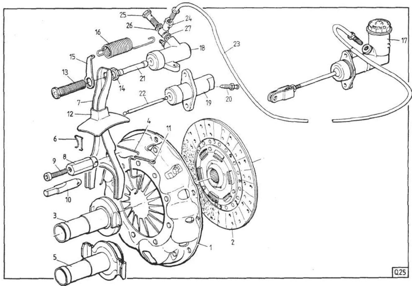
Page 2
SECTION QB
CLUTCH SYSTEM DIAGRAM
Key to Clutch System Drawing
-
Cover/Pressure Plate Assembly.
-
Centre Plate.
-
Release Bearing/Carrier Assembly. (Cast Type)
-
Spring, Fork to Carrier.
-
Release Bearing/Carrier Assembly (Fabricated Type)
-
Spring, Fork to Carrier.
-
Release Fork.
-
Pivot, Release Fork, S3
-
Screw, Pivot Ball.
-
Pivot, Release Fork, Turbo.
-
Split Pin, Fork to Pivot.
-
Grommet, Release Fork.
-
Adjuster Screw, Release Fork.
-
Locknut, Adjuster.
-
Lug, Return spring.
-
Return Spring, Release Fork.
-
Master Cylinder.
-
Slave Cylinder, S3.
-
Slave Cylinder, Turbo.
-
Bleed Nipple.
-
Pushrod, S3.
-
Pushrod, Turbo.
-
Flexible Hydraulic Pipe.
-
Banjo.
-
Banjo Bolt.
-
Washer, Large.
-
Washer, Small.
GENERAL DESCRIPTION
The clutch assembly comprises a diaphragm spring pressure plate with a single driven, dry friction plate. The friction plate is free to slide along the splines of the clutch shaft whose rear end is splined into the gearbox primary shaft and whose front end is supported by a needle roller bearing in the rear of the crankshaft.
The clutch release is operated hydraulically via a master cylinder at the pedal box and a slave cylinder on the clutch bellhousing. On Series 3 models until late '84, the slave cylinder is mounted on top of the clutch housing together with a release fork 'pull off' spring. Series 3 cars from late '84 and all Turbo models use a self adjusting slave cylinder mounted on the right hand side of the clutch housing.
QB 1 - ADJUSTMENT
1 Pedal
With the clutch pedal fully depressed and the master cylinder bottoming out, check the clearance between the lower edge of the clutch pedal pad (metal) and the GRP body. If necessary, adjust the clutch master cylinder pushrod length to achieve a clearance of 2 - 5 mm, i.e. the pedal should just touch the carpet.
- With the clutch pedal released, adjust the pedal upstop (if fitted), or discard if necessary to achieve 2 - 5 mm upward free play of the pedal, i.e. the master cylinder is 'topping out'.
If the master cylinder piston is restricted from reaching its full travel in either direction clutch drag and/or slip will result.
If necessary, adjust the brake pedal pushrod length to obtain compatible pedal heights.
Thus set up the clutch pedal should require adjustment only after replacement of a pedal box component.
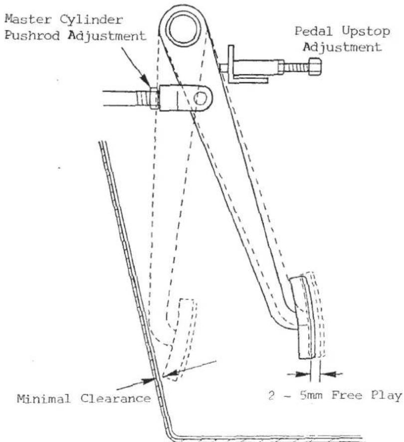
RELEASE FORK
The side mounted clutch slave cylinder (Series 3 after late '84 and all Turbos) is self adjusting, with fluid being returned to the master cylinder as the friction plate wears in service and the slave cylinder piston is pushed progressively further back on its return stroke. The "adjuster" in the release fork end should be set such that 22mm of adjuster projects beyond the locknut as shown in the diagram.
NOTE A previous specification called for the "adjuster" to be screwed in fully. However, the 22mm setting allows a greater degree of clutch friction plate wear to take place before the slave cylinder piston 'tops out' on its return stroke causing clutch slip and indicating that clutch replacement is necessary.
CAUTION: An adjuster setting of less than 22mm may cause damage to pressure plate and flywheel, and/or incomplete disengagement.

SECTION QB
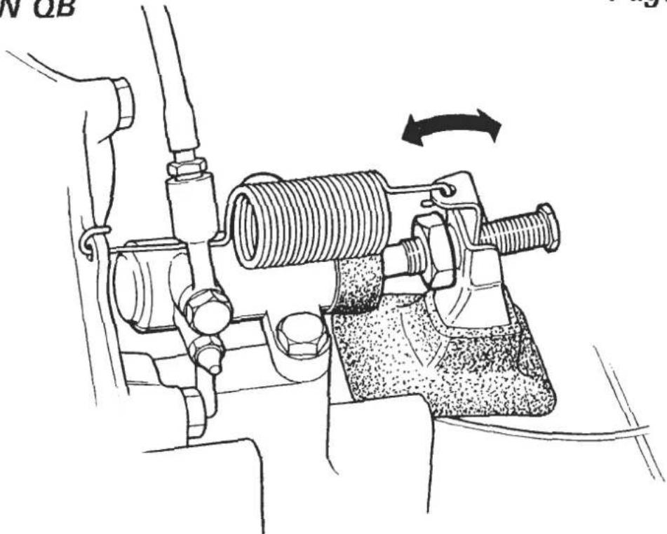
Series 3 cars up to late '84 with the top mounted slave cylinder, require checking for release fork clearance at service intervals in the following manner:
i) At the slave cylinder end, unhook the release fork spring, and measure the free play at the end of the release fork.
ii) If necessary, slacken the locknut and adjust to obtain 3 mm movement. Early Series 3 cars were not fitted with a locknut, but their use is recommended to improve adjustment retention.
iii) After adjustment, tighten locknut and refit spring. As the centre plate wears in service the clearance will reduce.
QB 2 - HYDRAULIC UNITS
Service kits are available for both the master and slave cylinders.
Before commencing work on the hydraulic system, take precautions as necessary to protect paintwork from brake fluid spillage.
NOTE: For cleaning purposes use ONLY commercial alcohol, methylated spirit or brake fluid. On no account should mineral based fluids such as petrol or paraffin be used.
On reassembly, coat the piston seals with rubber grease before inserting into the cylinder, refit the cylinder and bleed the hydraulic system of air.
QB 3 - CLUTCH ASSEMBLY
The gearbox or engine/gearbox assembly must first be removed from the vehicle before access to the clutch centre plate or spring/pressure plate may be obtained. If the gearbox assembly is to be removed from a Turbo model, it may be found easier if the turbocharger is first removed.
Before re-assembly, ensure that the spigot bearing and Nylatron thrust washers are correctly fitted (see QB 5), and that a small quantity of molybdenum disulphide lithium base grease (NLGl No. 2) is applied to the clutch splines.
Torque the clutch assembly to flywheel bolts to 2.3 - 2.6 kg f.m (17 - 19 lbf ft).
Note that if the clutch housing is to be replaced, the gearbox casing must be returned to the factory for mating and machining.
A revised clutch cover (pressure plate assembly) has been fitted to all Esprit Turbo models from engine number 22728.
This new cover has a diaphragm spring with curved fingers, instead of straight as used previously. This necessitates a corresponding change to the release bearing assembly from a curved thrust face to a flat face.
It is most important that 'old' and 'new' specification components are not mixed on the same vehicle although later type covers and release bearings may be used as a pair on any car.
QB.4 - RELEASE BEARING
Several different types of release bearing have been used, and great care must be taken to ensure the correct fitment.
Summary - Series 3: Prior to the introduction of the C35 type gearbox (late 1983) Series 3 cars were fitted with a cast iron release bearing carrier, whereas C35 equipped cars use a fabricated carrier. Both types use a flat face adaptor profile.
Turbo: All Turbo models use the fabricated type release bearing carrier, but with two types of adaptor profile. Prior to Eng. No. 22728, a curved profile was used (for straight diaphragm fingers) whilst later cars use a flat profile (for curved fingers). Earlier cars may however be fitted with the later clutch cover and release bearing as a pair. See Parts List for details.
On reassembly, lubricate the outer surface of the release bearing carrier with molybdenum disulphide, lithium base grease (NLG1 No.2) and apply also to the contact points of release arm and carrier, release arm pivot, release arm adjuster to pushrod, and sparingly to the front face of the release bearing.
Fit the bearing carrier into the guide tube and clip to the release arm.
SECTION QB
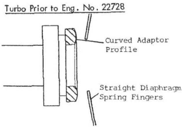

QB 5 - SPIGOT BEARING
The spigot bearing (A907E 6319F) must be fitted into the crank with its identifying numbers facing outwards (i.e. towards gearbox), and pressed in ONLY UNTIL FLUSH with the rear face of the crank. Ensure the bearing is lubricated with either Esso Unirex N3, or Shell Alvania R2 or R3.

It is essential that the Nylatron thrust washer (Ao79F 4029F) is fitted between clutch shaft and spigot bearing as shown.
QB 6 - CLUTCH SHAFT
The clutch shaft is splined into the gearbox primary shaft and retained by a circlip and spring.
Old type clutch shaft A079F 6066F has been replaced by modified shaft B085F 4068J which incorporates a hardened steel sleeve (A089F 0404F), to run inside the spigot bearing. This sleeve is fitted to the shaft using Permabond A148, and if there is any doubt about the security of the sleeve, it should be removed and refitted as follows:-
i) Roughen inside surface of sleeve with 320 grade emery paper. Degrease, clean and dry.
ii) Apply Permabond Al48 (A089F 6060) to spigot shaft and inside surface of sleeve. Fit sleeve onto shaft and rotate two or three times to ensure even distribution of adhesive.
iii) Remove sleeve, re-apply adhesive and repeat ii)
iv) To ensure sleeve to shaft concentricity, the final fitting should be performed with the spigot shaft in a vertical position and left in this position until cured i.e. cannot be moved with light finger pressure (approximately 1/2 - 1 hour).
NOTE: Ensure that all traces of adhesive are removed from the clutch shaft splines before re-assembly of the clutch.
NOTE: Earlier modified shaft A085F 4068J used a shorter (15mm) sleeve A089F 0400F, which may be replaced by the longer (18.5) sleeve A089F 0404F.
INTERIOR TRIM
SECTION VB - ESPRIT S3 & TURBO
| Operation | Page | |
| Centre Console | VB 1 | 2 |
| Tunnel Sides | VB 2 | 2 |
| Instrument Binnacle | VB 3 | 3/4 |
| Fascia | VB 4 | 4 |
| Cant Rails | VB 5 | 5 |
| 'A' Post Covers | VB 6 | 5 |
| Windscreen Header Rail | VB 7 | 5 |
| Rear Bulkhead Trim | VB 8 | 5/6 |
| Door Trim Panel | VB 9 | 6 |
VB.1. - CENTRE CONSOLE
To remove:
- Pull off centre tunnel top armrest.
- Release three screws securing choke/window switch panel and lay aside.
- Remove radio, or radio blanking panel and release knobs from heater a/c control panel. Remove graphic control panel.
- On cars prior to VIN 82/85 D2153, release the heater a/c controls from their light box.
- On cars after VIN 82/85 D2270, release the two wing nuts, via the radio aperture, securing the top of the centre console.
- Release the fixing at the rear of the console and remove the gear lever knob. Withdraw the console, unhooking the tongue at its front end from the fascia.
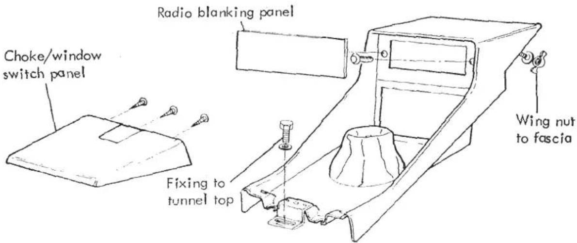
VB.2. - TUNNEL SIDES
After removing the centre console (VB.1) release the two screws each side securing the tunnel side to the fascia, and four screws into the tunnel top. Release the rear bulkhead trim fixings if necessary to enable the rear end of the tunnel side to be withdrawn.
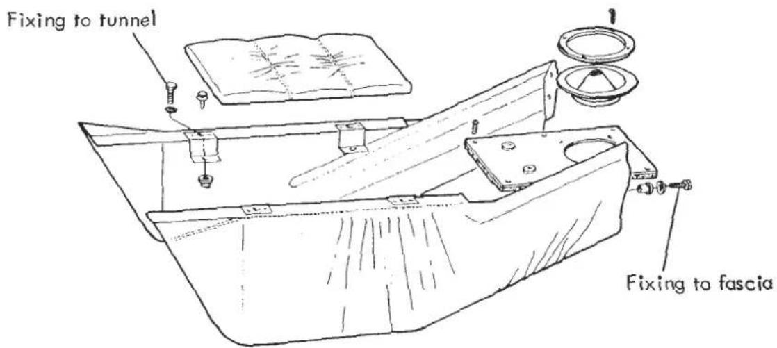
VB.3. - INSTRUMENT BINNACLE
Domestic & R.O.W. cars. Before the binnacle may be removed, it is necessary to dismantle the instrument/switch panels in order to disconnect the wiring harness, speedo cable, oil and boost pipes, and screen vent ducting.
Prior to 1985, Series 3 cars used a binnacle layout similar to that of S2 models, with slider type heater controls in the right hand side, and a face level vent in the left. The centre instrument panel and side switch panels must be released and the wires marked and disconnected from the switches and gauges. Release the speedo cable, oil pressure gauge pipe, heater cables and vent ducting.
During 1985, the Series 3 fascia and binnacle was changed to that of the DOM/ROW Turbo type. On these cars, the rheostat knobs are pulled off to reveal two of the four instrument mask screws. After removing the instrument mask and mounting panel the switch side panels and masks are released by removing the screws on the binnacle underside.

The binnacle, complete with mounting bracket, is removed by releasing the four bolts securing the mounting bracket to the scuttle cross beam, accessible from within the binnacle.
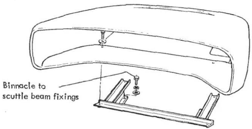
U.S.A (Federal) Models
On these cars it is not necessary to dismantle the instrument panels to remove the binnacle. Release the four bolts beneath the fascia securing the binnacle mounting bracket to the scuttle cross beam. Raise the binnacle sufficiently to enable the wiring connector blocks speedo cable, oil pressure and boost gauge pipes and demist vent hose to be disconnected.

VB.4 - FASCIA
Mounting bracket to scuttle fixing bolt
To Remove:
- Remove centre console (VB.1), steering wheel, column shrouds column switches.
- Remove instrument binnacle (U.S.A.) or dismantle instrument/ switch plates (DOM/ROW) to disconnect harness, pipes and cables.
- Release the three fixings securing the glovebox floor to the fascia and remove the 'A' post covers (VB.6)
- Release the four M6 nuts securing the fascia to the scuttle beam, and the two screws securing the lower edge of the fascia to the 'A' post. Release the single fixing on the tunnel top.
- Withdraw the fascia whilst disconnecting face level vent hoses, courtesy light switch leads, wiring harness clips etc. Leave glovebox fixed to scuttle beam.

VB.5. - CANT RAILS
The cantrails are secured by a single screw at their front end, by two screws from outside the door aperture and, on sunroof models, by the trim material wrapped into the roof aperture.
VB.6. - 'A' POST COVERS
Remove cant rail (VB.5) and pull off door seal from around front of door aperture. Peel off 'A' post trim from aperture and pull trim cover out, sideways from its three push fixings.
VB.7. - WINDSCREEN HEADER RAIL
On cars with a glass, or removeable roof panel pull off the weatherstrip from the front of the aperture and peel off the header rail trim material. Remove one cant rail (VB.5) and release the top of that sides 'A' post cover. Release the four screws securing the header rail and withdraw, whilst disconnecting the clock leads.

VB.8 - REAR BULKHEAD TRIM
Pull off the weatherstrip from around the rear of both door apertures, and on glass or removeable roof cars, from the rear of the roof aperture, and peel off the trim material. Release seat belt fixing from sill.
On U.S.A. cars, the tailgate release handle must be released from the bulkhead (see BD.12). Remove the four screws securing the trim panel to the bulkhead, and on sun roof models, the screw above each roof catch, concealed by the ABS trim. Withdraw the bulkhead trim, unclipping the top edge on solid roof cars from the fixing dowling.

VB. 9 - DOOR TRIM PANEL
The trim panel is secured by a single screw at the front and rear of the panel, a lip along the top edge and the interior release handle bezel. To remove the bezel, slacken the two screws securing the handle to the door and slide out the two halves of the bezel.
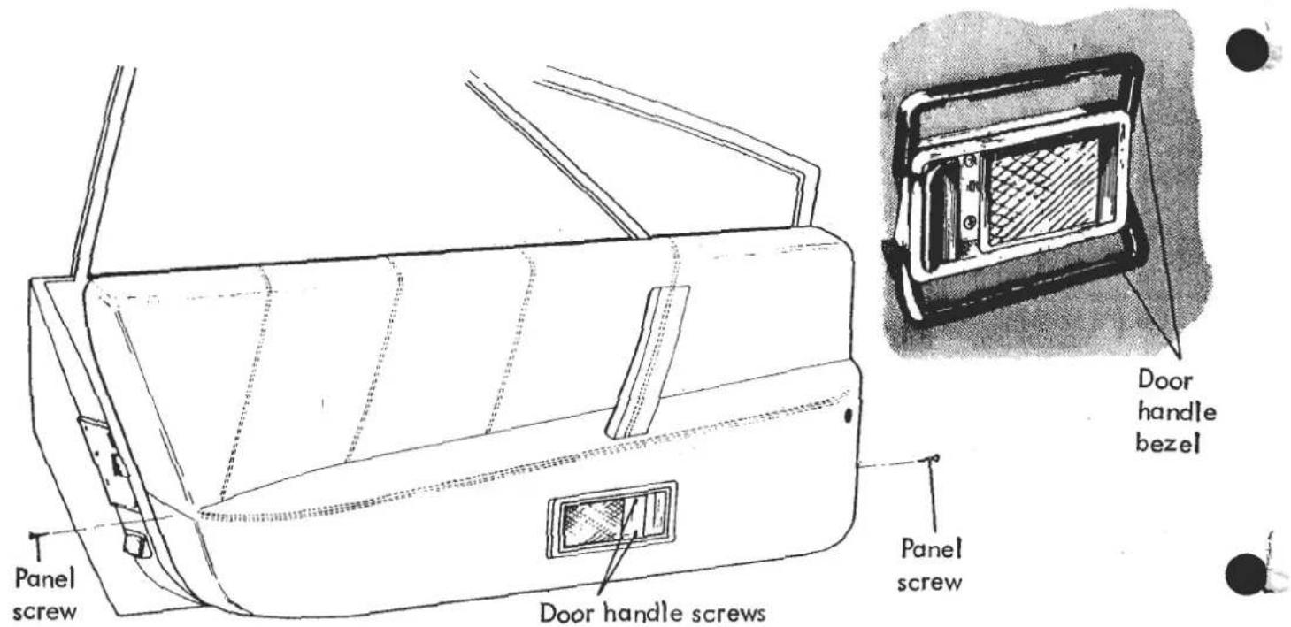

turbo esprit

SERVICE PARTS LIST
1980-87 Model Years

Lotus Cars Limited
Norwich, Norfolk, NR14 8EZ, England. Telex 97401
Telephone: (0953) 608000 Telefax: (0953) 606884
turbo esprit
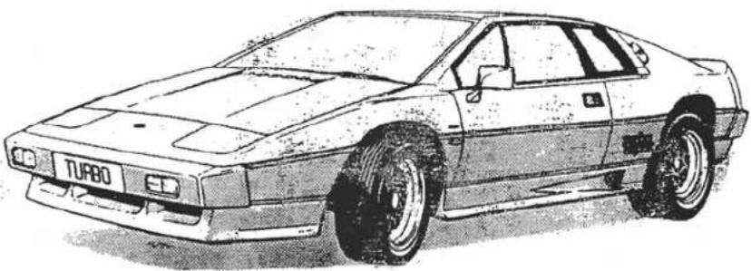
SERVICE PARTS LIST
Part No. E082T0325J
© Lotus Cars Ltd.: 1987
VEHICLE IDENTIFICATION NUMBER
The Vehicle Identification Number (VIN) is stamped on a plate fixed to the right or left hand front wheelarch inside the front luggage compartment. This number is repeated on the right hand side of the chassis frame, visible from within the right hand front wheelarch. This number should be quoted in all enquires regarding the vehicle. The seventeen characters of the VIN are coded in accordance with EEC directives as follows:
NOTES
- Seperate serial number sequences are used for the following groups of chassis market (character 12);
D A,E,G,H,S
- For change point identification in Service Notes, Parts Lists and Service Bulletins, the following VIN characters ONLY will be quoted;
Domestic & Export - 5,6,12,14 to 17
Example A typical change point could be listed as follows; 82 D 1100 (Domestic Turbo 1100) 82 A/E/G/H/S 0341(Export Turbo 0341) Note that two Numbers are needed to identify the single change point due to the different serial number sequences outlined in note 1. If a dash is used in place of the chassis market letter code (e.g. 82 - 0341), this is the change point for all markets not otherwise li

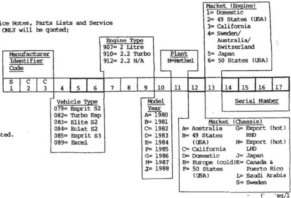
| Function Code | Contents | Function Code | Contents |
| 10.00 | BODY STRUCTURE | 34.00 | WHEELS & TYRES |
| 10.01A | Body Repair Sections, Front | 34.01A | Wheels, Tyres, Spare Wheel Retention |
| 10.02A | Body Repair Sections, Rear | 40.00 | ENGINE |
| Timber Bulkhead, Speaker Bins | 40.01A | Block, Main Bearing Housing, Mountings | |
| 10.05A | Seat Belt Mounting Beam, Scuttle Beam, Jacking | 40.03A | (Wet Sump Only) Sump |
| Plates, Seat Belt Sill Plates | 40.05A | Cylinder Head | |
| 10.07A | Headlamp Pods, Pod Pivots | 40.07A | Prior '87 M.Y. Camshafts, Cam Housings |
| 10.09A | Front Bonnet & Release Mechanism | 40.07B | '87 M.Y. On. Camshafts, Cam Housings |
| 10.11A | Tailgate & Release Mechanism | 40.09A | Pistons & Liners. Con. Rods |
| 10.13A | Engine Compartment | 40.11A | Crankshaft & Flywheel |
| 10.15A | Door Shell, Door Beam, Hinge Post | 40.13A | Water Pump |
| 10.17A | Door Handles, Lock Mechanism, Striker Post | 40.15A | Aux. Hsg. Oil Pump, Filter, Turbo Lubrication |
| 10.23A | Bumpers, Sills, Valence, Spoiler | 40.15B | (Dry Sump Only) Scavenge Manifold, Oil Pump, Oil Tank |
| 11.00 | GLAZING, DOOR WEATHERSTRIPS, WINDOW LIPT | ||
| 11.01A | Glass, Finishers, Door Weatherstrips | 40.17A | Distributor, Ignition System, Coil Box |
| 11.02A | Door Window Frame, Lift Mechanism | 40.19A | Alternator, Starter Motor |
| 11.05A | 'Glass Roof' | 40.21A | Exhaust Manifold, Turbocharger, Wastegate |
| 12.00 | EXTERIOR HARDWARE & TRIMS | 40.23A | A/C Compressor |
| 12.01A | Capp. Rails, Air Scoops, 'B'Post Fin. Wind Defl. | 40.27A | '87 M.Y. On. Vacuum Pump, Brackets, Pulley |
| 12.05A | Waistband Finisher, Decals | 40.28A | Engine Upper Gasket Set |
| 12.09A | Door Mirrors | 40.28B | Engine Lower Gasket Set |
| 13.00 | SEATS & SEAT BELTS | 41.00 | BELPS & PULLEYS |
| 13.03A | Seat Frames & Runners | 41.01A | Prior '87 M.Y. Camshaft Belt, Pulleys, Tensioner |
| 13.09A | Seat Foams, Suspension & Backboard | 41.01B | '87 M.Y. On. Camshaft Belt, Pulleys, Tensioner |
| 13.11A | Trimmed Seats, Trimmed Backboard | 41.03A | Auxiliary Belts, Pulleys |
| 13.27A | Seat Belts, Reel Cover | 42.00 | INDUCTION SYSTEM |
| 14.00 | PEDAL BOX & FASCIA | 42.01A | Airbox, Diffuser, Plenum Chamber, Engine Bay Ducting |
| 14.01A | RHD Pedal Box, Throttle & Choke Cables | 42.03A | Carburettor Assys. Fuel Regulating Valve |
| 14.01B | LHD Pedal Box, Throttle & Choke Cables | 42.04A | Carburettor Internal Components |
| 14.05A | Fascia Trimmed Panels. Column Shroud | 42.07A | Prior '87 M.Y. Inlet Manifold, Water Rail, Vacuum Rail |
| 14.07A | Binnacle Instrument Panels & Masks | 42.07B | '87 M.Y. On. Inlet Manifold |
| 14.08A | Centre Console, Light Box, G/Lever Gaiter | 43.00 | EMISSION EQUIPMENT |
| 14.10A | Trimmed Instrument Binnacle | 43.03A | '87 M.Y. On. Engine Management System, Vacuum Pipes |
| 14.12A | Glovebox | 44.00 | FUEL SYSTEM |
| 15.00 | INTERIOR TRIM | 44.01A | Fuel Tanks, Pillers, Sender Unit |
| 15.01A | Roof Trim, Mirror, Sun Visors | 44.03A | Pump, Filter, Pipes |
| 15.11A | Rear Bulkhead Trim | 44.05A | Fuel Tank Breather System |
| 15.13A | Door Trim, (Ashtray in Door) | 45.00 | EXHAUST |
| 15.19A | Tunnel Trim, G/Lever Lower Gaiter | 45.03A | Exhaust System, Mountings |
| 15.24A | Rear Luggage Compartment Carpet | 45.05A | Heat Shields |
| 15.30A | Passenger Compartment Carpet. H/Brake Gaiter | 46.00 | COOLING |
| 16.00 | SCUND INSULATION | 46.01A | Prior '87 M.Y. Radiator Fans, Pipes, Header Tank, Rad. Duct |
| 16.01A | Passenger Compartment Insulation | 46.01B | '87 M.Y. ON. Radiator Fans, Pipes, Header Tank, Rad. |
| 16.02A | Duct Body Underside Insulation | 46.03A | Oil Cooler, Hoses, Thermostat |
| 17.00 | ELECTRICAL | 47.00 | TRANSMISSION |
| 17.01A | Harness & Leads | 47.01A | Clutch, Release Mechanism |
| 17.03A | Relays, Delay Units, Horns | 47.02A | 'C35' Gearbox Identification |
| 17.05A | Switches, Fibre Optics | 47.03A | G/Box Assy. Mountings, Clutch Housing, Speedo Drive |
| 17.07A | Instruments, Tell Tale Lamps | 47.05A | Gear Lever, External Gearchange Linkage |
| 17.09A | Speedo Cable, Oil/Boost Pipes | 47.06A | Top Cover, Selector Mechanism (Internal) |
| 17.11A | Exterior Lamps, Except Headlamps | 47.07A | Gears, Shafts, Bearings |
| 17.13A | Headlamps & Surrounds | 47.11A | Crownwheel & Pinion, Differential |
| 17.15A | Headlamp Lift Mechanism | 47.15A | Output Shafts, Housings, Bearings |
| 17.17A | Interior Lamp, Courtesy Switches | 60.00 | TOOLS |
| 17.19A | Fuse Boxes, Thermal Trip, Inertia Switch | 60.01A | Tool Kit, Jack & Stowage |
| 17.21A | Windscreen Wiper & Washer | 60.02A | Special Tools |
| 17.27A | Radio/Cassette, Speakers, Aerial | 60.04A | Transmission Tools - |
| 17.29A | Suppression Devices | 80.00 | EULK ITEMS |
| 17.31A | Battery, Battery Cables | 80.20A | Paint Codes & Touch-in Paint |
| 18.00 | HEATER/AIR CONDITIONING | ||
| 18.01A | Heater A/C Casing | ||
| 18.03A | Air Conditioning Plumbing | ||
| 18.05A | Heater Plumbing | ||
| 18.07A | Blower Motors | ||
| 18.09A | Mechanically Operated Parts & Controls | ||
| 18.11A | Vacuum Operated Parts & Controls | ||
| 18.13A | Trunking, Vents, Plenum Chamber | ||
| 30.00 | CHASSIS | ||
| 30.01A | Chassis Frame | ||
| 31.00 | SUSPENSION | ||
| 31.01A | Prior to '85 M.Y. Front Suspension | ||
| 31.01B | '85 M.Y. On. Front Suspension | ||
| 31.03A | Rear Suspension & Drive Shafts | ||
| 32.00 | STEERING | ||
| 32.01A | Steering Rack Assy. Intermediate Column | ||
| 32.05A | Steering Column, Lock, Wheel | ||
| 33.00 | BRAKES | ||
| 33.01A | Prior to '85 M.Y. Calipers & Discs | ||
| 33.01B | '85 M.Y. On. Calipers & Discs | ||
| 33.03A | Prior to '85 M.Y. Hydraulic System, Servo | ||
| 33.03B | '85 M.Y. On. Hydraulic System, Servo | ||
| 33.05A | Handbrake |
PART NUMBERS
All part numbers commence with the vehicle type number, indicating the type of Lotus model on which the part was first used:
26,36,45,500.....ELAN
50.....ELAN +2
46,54,65,74.....EUROPA
75.....ELITE S1
76.....ECLAT S1
79.....ESPRIT S1/S2/S2.2
82.....ESPRIT TURBO
83.....ELITE S2
84.....ECLAT S2
85.....ESPRIT S3
89.....EXCEL
STANDARD HARDWARE PART NUMBERS
All standard finish bolts, screws, studs, nuts & washers, carry part numbers including the prefix A075W, B075W etc.,
ENGINE PART NUMBERS
All engine part numbers commence with the engine type number on which the part was first used:
907 - 2 Litre Naturally Aspirated 911 - 2.2 Litre Naturally Aspirated (Talbot)
910 - 2.2 Litre Turbocharged 912 - 2.2 Litre Naturally Aspirated (Lotus)
This publication has been designed primarily for Lotus Dealers, and will be updated by issue of Service Bulletins to Lotus Dealers when necessary. Lotus policy is one of continuous product improvement and the right is reserved to alter specifications at any time without prior notice.
Whilst every care has been taken to ensure correctness of information, it is impossible to guarantee complete freedom from omissions and errors, or to accept liability arising from such omissions and errors, but nothing contained herein shall affect your statutory rights.
| ILLUSNO. | DESCRIPTION |  PART NUMBER PART NUMBER | QUANTITY | REMARKS | ||
| RHD | LHD | |||||
| 10.01A | ||||||
| 1 | Bodyshell (inc. sills)" " " " " " " " " " " " " " " " " " " " " " " " " " " " " " " " " " " " " " " " " " " " " " " " " " " " " " " " " " " " " " " " " " " " " " " " " " " " " " " " " " " " " " " " " " " " " " " " " " " " " | A082B4228K A082B4516K A082B4229K A082B4517K A082B4305K A082B4306K A082B4308K A082B4309K A082B4311K A082B4312K A082B4314K A082B4315K A082B4317K A082B4318K A082B4320K A082B4321K A082B4323K A082B4584K | 1 1 1 1 1 1 1 1 1 1 1 1 1 1 1 1 1 1 1 1 1 1 1 1 1 1 1 1 1 1 1 1 1 1 1 1 1 1 1 1 1 1 1 1 1 1 1 1 1 1 1 | NOT 'Glass Roof' 'Glass Roof' NOT 'Glass Roof' 'Glass Roof' | ||
| 2 | Body Section, Mid Nose, Full Width" " " " " " " " " " " " " " " " " " " " " " " " " " " " " " " " " " " " " " " " " " " " " " " " " " " " " " " " " " " " " " " " " " " " " " " " " " " " " " " " " " " " " " " " " " " " " " " " " " " " “ " " " " " " " " " " " " " " " " " " " " " " " " " " " " " " " " " " " " " " " " " " " " " " " " " " " " " " " " " " " " " " " " " " " " " " " " " " " " " " " " " " " " " " " " " " " " " " " " " " " ) | |||||
| 3 | Body Section, Mid Nose, LH Half" " " " " " " " " " " " " " " " " " " " " " " " " " " " " " " " " " " " " " " " " " " " " " " " " " " " " " " " " " " " " " " " " " " " " " " " " " " " " " " " " " " " " " " " " " " " " " " " " " " “ | |||||
| 4 | Body Section, Full Nose, Full Width" " " " " " " " " " " " " " " " " " " " " " " " " " " " " " " " " " " " " " " " " " " " " " " " " " " " " " " " " " " " " " " " " " " " " " " " " " " " " " " " " " " " " " " " " " " " " " " “ | |||||
| 5 | Body Section, Full Nose, RH Half" " " " " " " " " " " " " " " " " " " " " " " " " " " " " " " " " " " " " " " " " " " " " " " " " " " " " " " " " " " " " " " " " " " " " " " " " " " " " " " " " " " " " " " " " " " " " " " " " " “ | 1 1 1 1 1 1 1 1 1 1 1 1 1 1 1 1 1 1 1 1 1 1 1 1 1 1 1 1 1 1 1 1 1 1 1 1 1 1 1 1 1 1 1 1 1 1 1 1 1 2 | ||||
| 6 | Body Section, Full Nose, LH Half" " " " " " " " " " " " " " " " " " " " " " " " " " " " " " " " " " " " " " " " " " " " " " " " " " " " " " " " " " " " " " " " " " " " " " " " " " " " " " " " " " " " " " " " " " " " " " " “ | Turbo 10.01A | ||||
| 7 | Body Section, Roof (NOT 'Glass' Roof) Body Section, Roof ('Glass Roof' Models) | A082B4323K A082B4584K | 1 1 1 1 1 1 1 1 1 1 1 1 1 1 1 1 1 1 1 1 1 1 1 1 1 1 1 1 1 1 1 1 1 1 1 1 1 1 1 1 | |||

TURBO
10.02A


| ILLUSNO. | DESCRIPTION | PART NUMBER | QUANTITY | MAY 1991REMARKS | |
| ALL | |||||
| 10.02A | |||||
| 1 | Body Section, Short Rear, Full Width | A082B4324K | 1 | Not 'Glass Roof' 'Glass Roof' Models | |
| 2 | Body Section, Short Rear, RH Half | A082B4326K | 1 | ||
| 3 | Body Section, Short Rear, LH Half | A082B4328K | 1 | ||
| 4 | Body Section, Full Rear, Full Width | A082B4330K | 1 | ||
| 5 | Body Section, Full Rear, RH Half | A082B4332K | 1 | ||
| 6 | Body Section, Full Rear, LH Half | A082B4334K | 1 | ||
| 7 | Bulkhead, Upper, (Timber) | G079B4000F | 1 | ||
| Bulkhead, Upper, (Timber) | B082B4497F | 1 | |||
| 8 | Bulkhead, Centre, (Timber) | F079B4001F | 1 | ||
| 9 | Bulkhead, Lower, (Timber) | J079B4002F | 1 | ||
| Speaker Enclosure, Rear Bulkhead (ABS) | A082B4302K | 2 | |||
| d4p2 | Turbo 10.02A | ||||

TURBO 10.05A


| ILLUSNO. | DESCRIPTION | PART NUMBER | QUANTITY | MAY 1931REMARKS | |
| ALL | |||||
| 10.05A | |||||
| 1 | Cross Beam, Scuttle, RHD | E079U4196J | 1 | ||
| Cross Beam, Scuttle, LHD | E079U4097J | 1 | |||
| 2 | Setscrew, M8 x 25, Beam to Hinge Post | A075W1039F | 4 | ||
| 3 | Setscrew, M8 x 20, Beam to Hinge Post | A075W1038F | 2 | ||
| 4 | Washer, Spring, Beam to Hinge Post | A075W4036F | 6 | ||
| 5 | Washer, Plain, Beam to Hinge Post | A075W4020F | 6 | ||
| 6 | Crossbeam, Rear Bulkhead, Seat Belt Mtg. | J079U4309J | 1 | ||
| 7 | Bolt, Thinhead, Beam End to Door Aperture | A079U4317F | 4 | ||
| 8 | Washer, Large O/D | A075W4021F | 4 | ||
| 9 | Nut, M8 | A075W3021F | 2 | ||
| 10 | Setscrew, M6 x 25, Beam to Bulkhead | A075W1031F | 12 | ||
| 11 | Washer, Large O/D | A075W4017F | 12 | ||
| 12 | Nut, Nyloc, M6 | A075W3009F | 7 | ||
| 14 | Plate, Seat Belt Mounting to Sill, LH | D079U4213K | 1 | ||
| 15 | Plate, Seat Belt Mounting to Sill, RH | D079U4214K | 1 | ||
| 16 | Bolt, M8 x 25, Mounting Plate to Sill | A075W1039F | 6 | ||
| 17 | Washer, Large O/D Special | A075W4021F | 2 | ||
| 18 | Washer, Flat | A075W4002F | 4 | ||
| Stiffener Bracket, Tailgate Aperture, RH | B082U4739K | 1 | Dry Sump Cars | ||
| 20 | Stiffener Bracket, Tailgate Aperture, RH | A085U4824K | 1 | Wet Sump Cars Prior '87 M.Y. | |
| Stiffener Bracket, Tailgate Aperture, RH | A085U5727K | 1 | '87 M.Y. on, With Purge Pump Bracket | ||
| 21 | Stiffener Bracket, Tailgate Aperture, LH | C082U4710K | 1 | ||
| 22 | Setscrew, Thinhead, M8, Brkt/Aperture | A075W1081F | 4 | 2 Only if Gas Struts anchored in aperture | |
| 23 | Washer, Flat | A075W4002Z | 4 | ||
| 24 | Setscrew, M8 x 25, Brkt/Body | A075W1039Z | 4 | Brkt/Oil Tank on Dry Sump Cars | |
| 25 | Washer, Large O/D, Brkt/Body | A075W4021Z | 8 | 6 On Dry Sump Cars | |
| 26 | Nut, Nyloc, M8, Brkt/Body | A075W3010F | 4 | 2 On Dry Sump Cars | |
| 27 | Jacking Plate | A085U4792F | 4 | '85 M.Y. on | |
| Jacking Plate | A082U5023J | 4 | With Stepped Joint Face Prior to Body Mod. | ||
| 28 | Pop Rivet, Jacking Plate to Body | A075W6092F | 8 | ||
| Tow Eye, Front | A085B4399F | 1 | ) | ||
| Reinforcing Plate, Tow Eye | A085B4398F | 1 | ) | ||
| Setscrew, M6 x 20, Tow Eye | A075W1030Z | 5 | )Germany Only | ||
| Washer, Flat, Tow Eye | A075W4013Z | 5 | ) | ||
| d4p3 | Turbo 10.05A | ||||
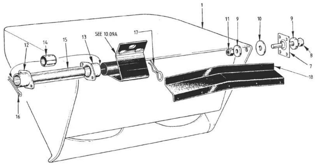
TURBO
10.07A


| ILLUSNO. | DESCRIPTION |  PART NUMBER PART NUMBER | QUANTITY | MAY 1991REMARKS | |
| ALL | |||||
| 10.07A | |||||
| 1 | Headlamp Pod, RH | A082B4468J | 1 | Lucas/Hella HeadlampsCibie HeadlampsLucas/Hella HeadlampsCibie Headlamps | |
| Headlamp Pod, RH | A085B4378J* | 1 | |||
| Headlamp Pod, LH | A082B4469J | 1 | |||
| Headlamp Pod, LH | A085B4379J* | 1 | |||
| 7 | Ball Joint, Pod Outer Pivot | A079U4652F | 2 | ||
| Pop Rivet, Ball Joint Fixing | A075W6090Z | 8 | |||
| 8 | Setscrew, M6 x 30, Pod Outer Pivot | A075W1032Z | 2 | ||
| 9 | Washer, Flat, Pod Outer Pivot | A075W4015Z | 4 | ||
| 10 | Washer, Large O/D, Pod Outer Pivot | A075W4065Z | 2 | * Cars prior VIN 82 D 226582 - 0624Will also require new Headlamp surround. 17.13A | |
| 11 | Nut, Nyloc, M6, Pod Outer Pivot | A075W3009Z | 2 | ||
| 12 | Bearing Housing, LH Outer/RH Inner | A079U4451F | 2 | ||
| 13 | Bearing Housing, RH Outer/LH Inner | A079U4452F | 2 | ||
| Pop Rivet, Bearing Housing Fix | A075W6090Z | 8 | |||
| 14 | Bearing Bush, Pod Inboard Pivot | A079U6030F | 4 | ||
| 15 | Hinge Pin, Pod/Bonnet | A079U4456F | 2 | ||
| 16 | Split Pin, Hinge Pin Retention | A075W6009Z | 2 | ||
| 17 | 'R' Pin, Hinge Pin | A079W6177F | 2 | ||
| 18 | Water Shield | B079U4459K | 2 | ||
| Pop Rivet, Shield to Body | A075W6094Z | 6 | |||
| d4p4 | Turbo 10.07A | ||||

| ILLUS NO. | DESCRIPTION |  PART NUMBER PART NUMBER | QUANTITY | MAY 1991REMARKS | |
| ALL | |||||
| 10.09A | |||||
| 1 | Bonnet Panel | A079B4024J | 1 | )Up to VIN 82 D 1060) 82 - 0337) R/B Bonnet B085B4357J) with Seal and Hinges | |
| 2 | Seal Bonnet | A079U4007F | 1 | ||
| 3 | Hinge, Bonnet, LH | A079U4480F | 1 | ||
| 4 | Hinge, Bonnet, RH | B079U4457F | 1 | ||
| 1 | Bonnet Panel, Six Slot | B085B4357J | 1 | >From VIN 82 D 1061) 82 - 0338) | |
| Bonnet Panel, Two Slot | C082B4629J | 1 | |||
| 2 | Seal, Bonnet | A082U6077F | 1 | ||
| 3 | Hinge, Bonnet, LH | B085U4797K | 1 | ||
| 4 | Hinge, Bonnet, RH | B085U4798K | 1 | ||
| 5 | Stiffener, Bonnet, Front Edge Curvature | A079B4064F | 1 | R/B B082B4473FIncluded in Bonnet Panel | |
| Stiffener, Bonnet, Front Edge Curvature | B082B4473F | 1 | |||
| 6 | Shim Plate, Hinge to Bonnet | C079U4484K | A/R | ||
| 7 | Setscrew, M6 x 18, Hinge to Bonnet | A075W1029Z | 6 | ) Alternatives | |
| Setscrew, M6 x 16, Hinge to Bonnet | A075W1026Z | 6 | |||
| 8 | Washer, Shakeproof, Hinge to Bonnet | A075W4046Z | 6 | ||
| 9 | Washer, Flat, Hinge to Bonnet | A075W4065Z | 6 | ||
| 10 | Tapping Plate, Bonnet Hinge | A079U4458K | 2 | ||
| 11 | Grille, Bonnet | C079U4227F | 1 | ||
| Screw, Grille to Bonnet | A075W5014Z | 5 | )R/B Betaseal | ||
| Insert Bush, Grille to Bonnet | A075W6042Z | 5 | |||
| 12 | Striker, Bonnet Catch | A079U4266F | 2 | ||
| 13 | Shim Plate, Striker to Bonnet | A076U0618Z | A/R | ||
| 14 | Setscrew, MB x 25, Striker to Bonnet | A075W1039Z | 4 | ||
| 15 | Washer, Spring, Striker to Bonnet | A075W4036Z | 4 | ||
| 16 | Washer, Flat, Striker to Bonnet | A075W4020Z | 4 | ||
| 17 | Tapping Plate, Bonnet Striker | A079U4487F | 2 | ||
| 20 | Bracket, Bonnet Latch Disc Mounting | A079U4208F | 2 | ||
| 21 | Setscrew, 10 UNF x 3/4", Bracket/Body | A075W5061Z | 6 | ||
| 22 | Washer, Flat, Bracket/Body | A075W4000Z | 6 | ||
| d4p5 | Turbo 10.09APage 1 | ||||

| ILLUSNO. | DESCRIPTION |  PART NUMBER PART NUMBER | QUANTITY | MAY 1991REMARKS | |
| ALL | |||||
| 10.09A | |||||
| 23 | Latch Disc, Bonnet Lock | B079U4218F | 2 | ||
| 24 | Clevis Pin, Latch Disc to Bracket | A075W6033Z | 2 | ||
| 25 | 'R' Pin, Latch Disc Clevis | A075W6175Z | 2 | ||
| 26 | Washer, Flat, Disc to Bracket | A075W4020Z | 4 | ||
| 27 | Clevis Pin, Latch Rod to Disc | B079U4219F | 2 | ||
| 28 | Rod, Bonnet Latch Operating | C079U4222F | 1 | ||
| 29 | Bush & Clip, Rod to Cross Shaft | A075U6033K | 1 | ||
| 30 | Cross-Shaft, Bonnet Lock, RHD | A079U4221F | 1 | ||
| Cross-Shaft, Bonnet Lock, LHD | A079U4363F | 1 | |||
| 31 | Bracket, Cross-Shaft Pivot | A079U4220F | 2 | ||
| 32 | Setscrew, M6 x 12, Bracket to Body | A075W1027Z | 4 | ||
| 33 | Washer, Flat, Bracket to Body | A075W4013Z | 4 | ||
| 40 | Stay, Telescopic, Bonnet Support | A079U4277K | 1 | )Top Bracket Rivetted to Stay | |
| Stay, Telescopic, Bonnet Support | B079U4277K | 1 | )Top Bracket Bolted to Stay | ||
| Bracket, Bonnet Stay to Bonnet | A075U0385Z | 1 | )Use With B079U4277K | ||
| Gas Strut, Bonnet Support | C075U6032F | 1 | )Alternative | ||
| Bracket, Gas Strut to Bonnet & Wheelarch | A075U0385Z | 2 | |||
| Washer, Flat, Strut to Brackets | A075W4020Z | 2 | |||
| Nut, Nyloc, Strut to Brackets | A075W3010Z | 2 | |||
| 45 | Setscrew, Strut/Stay Bracket to Wheelarch | A075W1025F | 2 | M5 x 20 | |
| 46 | Nut, Nyloc, M5 " " " " | A075W3008Z | 2 | ||
| 47 | Washer, Flat " " " " | A075W4011Z | 2 | ||
| 48 | Washer, Large O/D " " " " | A075W4009Z | 2 | ||
| 49 | Setscrew, M5 x 12, Brkt. to Bonnet | A075W5085Z | 2 | ||
| 50 | Washer, Shakeproof, Brkt. to Bonnet | A075W4045Z | 2 | ||
| 51 | Jacknut, M5 " " | A076W3043F | 2 | ||
| Turbo 10.09APage 2 | |||||
| d4p6 | |||||


| ILLUSNO. | DESCRIPTION |  PART NUMBER PART NUMBER | QUANTITY | MAY 1991REMARKS | |
| FIXEDROOF | GLASSROOF | ||||
| 10.11A | |||||
| 1 | Tailgate Panel | A082B4263K | 1 | 1 | |
| 3 | Foam Seal, Tailgate to Engine Lid | A082U6065V | 2m | 2m | |
| 4 | Seal, Tailgate to Body | A079B4074F | A/R | A/R | On Body |
| Foam Strip, Tailgate to Body | A082U6067V | A/R | A/R | On Tailgate. If Fitted | |
| 6 | Hinge Blade, Tailgate, LH | E079U4061K | 1 | ||
| 7 | Hinge Blade, Tailgate, RH | E079U4062K | 1 | ||
| 8 | Bolt, Hinge Pivot | A079U4516F | 2 | ||
| 9 | Nut, Nyloc, M10, Hinge Pivot | A075W3011F | 2 | ||
| 10 | Hinge Blade, Tailgate, LH | A082U4969F | 1 | ||
| Hinge Blade, Tailgate, RH | A082U4970F | 1 | |||
| 11 | Bracket, Tailgate Hinge to Body | A082U4972F | 2 | ||
| 12 | Setscrew, Tailgate Hinge Pivot | A082W1077F | 2 | ||
| 13 | Washer, Shakeproof, T/Gate Hinge Pivot | A075W4049Z | 2 | ||
| 14 | Washer, Flat, T/Gate Hinge Pivot | A075W4024F | 4 | ||
| 15 | Setscrew, M8 x 25, Bracket to Body | A075W1039Z | 4 | ||
| 16 | Washer, Flat, Bracket to Body | A075W4020F | 4 | ||
| 17 | Washer, Large O/D, Bracket to Body | A075W4021F | 4 | ||
| 18 | Nut, Nyloc, M8, Bracket to Body | A075W3010Z | 4 | ||
| 19 | Gasket, Bracket to Body | A082U4973F | 2 | ||
| 20 | Setscrew, M8 x 25, Hinge Blade/Tailgate | A075W1029Z | 4 | 4 | |
| 21 | Washer, Spring, Hinge Blade/Tailgate | A075W4036Z | 4 | 4 | |
| 22 | Washer, Flat, Hinge Blade/Tailgate | A075W4020Z | 4 | 4 | |
| Tapping Plate, Hinge Blade, LH | B079U4063K | 1 | 1 | Inside Tailgate Panel | |
| Tapping Plate, Hinge Blade, RH | B079U4198K | 1 | 1 | Inside Tailgate Panel | |
| 23 | Louvre, Tailgate | C082B4282K | 1 | 1 | |
| 24 | Nut, Nyloc, M6 | A907E6285F | 6 | 6 | |
| 25 | Washer, Flat | B082W4018F | 6 | 6 | |
| Grommet, Louvre, Front Edge Fixings | A054J6005Z | 3 | 3 | ||
| 26 | Screw, Louvre, Side Fixing | A075W5027Z | 4 | 4 | |
| Gas Strut, Tailgate Support | A079U6013F | 2 | With Anchors on Body Aperture and Tailgate Edge | ||
| 27 | Gas Strut, Tailgate Support | A082U6074F | 2 | 2 | With Anchors on Cabin Bulkhead and Tailgate Inner Skin |
| Turbo 10.11APage 1 | |||||
| d4p7 | |||||
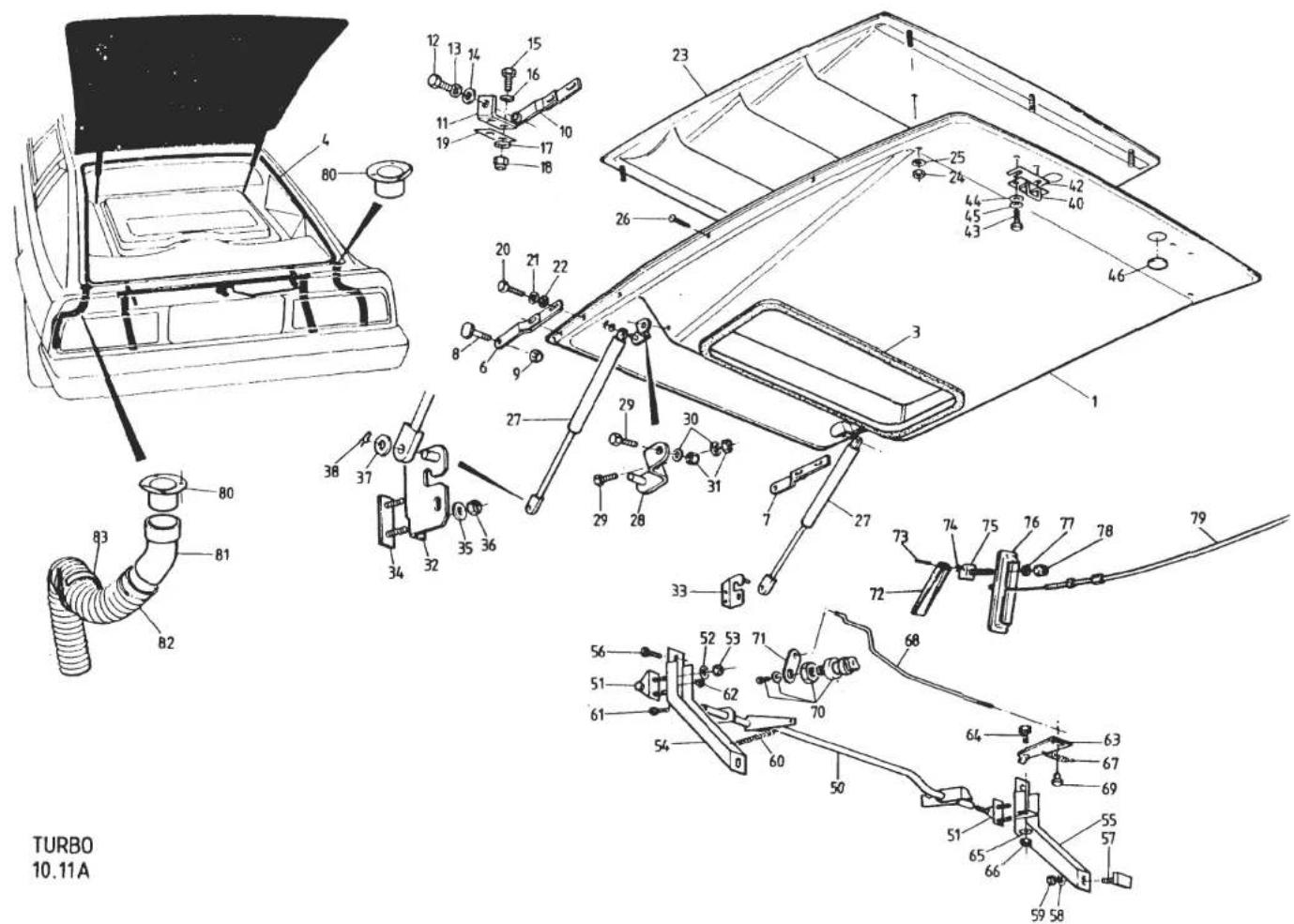


| ILLUS NO. | DESCRIPTION |  PART NUMBER PART NUMBER | QUANTITY | MAY 1991REMARKS | |
| FIXED ROOF | GLASS ROOF | ||||
| 10.11A | |||||
| 28 | Bracket, LH, Gas Strut to Tailgate | B082U4767F | 1 | 1 | ) |
| Bracket, RH, Gas Strut to Tailgate | B082U4768F | 1 | 1 | ) | |
| 29 | Setscrew, M6 x 30, Bracket to Tailgate | A075W1032F | 4 | 4 | ) |
| 30 | Washer, Flat, Bracket to Tailgate | A075W4015F | 4 | 4 | ) |
| 31 | Nut, Nyloc, M6, Bracket to Tailgate | A075W3009F | 4 | 4 | ) |
| 32 | Bracket, LH, Gas Strut to Cabin Bulkhead | B082U4765F | 1 | 1 | ) |
| 33 | Bracket, RH, Gas Strut to Cabin Bulkhead | B082U4766F | 1 | 1 | )For Use With Strut A082U6074F |
| 34 | Studplate, Bracket to Bulkhead | A082U4852F | 2 | 2 | ) |
| 35 | Washer, Flat, Bracket Fixing | A075W4013F | 4 | 4 | ) |
| 36 | Nut, Nyloc, M6, Bracket Fixing | A075W3009F | 4 | 4 | ) |
| 37 | Washer, Flat, Strut to Bracket | A075W4020F | 4 | 4 | ) |
| 38 | 'R' Pin, Strut to Bracket | A075W6175F | 4 | 4 | ) |
| 40 | Striker, Tailgate Latch | A079U4500F | 2 | 2 | |
| Tapping Plate, Striker | A079U4487F | 2 | 2 | Inside Tailgate Panel | |
| 42 | Shim Plate, Striker Adjustment | A076U0618F | A/R | A/R | |
| 43 | Setscrew, M8 x 20, Striker Fix | A075W1038Z | 4 | 4 | |
| 44 | Washer Flat, Striker Fix | A075W4020F | 4 | 4 | |
| 45 | Washer, Spring, Striker Fix | A075W4036Z | 4 | 4 | |
| 46 | Grommet, Tapping Plate Access | A054J6005Z | 2 | 2 | |
| 50 | Cross Shaft, Tailgate Latch | A082U4703F | 1 | 1 | |
| 51 | Bearing Bracket, Cross Shaft | B079U4501K | 2 | 2 | |
| 52 | Washer, Flat, Bearing Bracket Fix | A075W4020F | 4 | 4 | |
| 53 | Nut, Nyloc, M8, Bearing Bracket Fix | A075W3010F | 4 | 4 | |
| Support Bracket, LH, Latch Cross-Shaft | A079U4505K | 1 | )Lower End Fixes to Floor | ||
| Support Bracket, RH, Latch Cross-Shaft | A082U4700K | 1 | ) | ||
| 54 | Support Bracket, LH, Latch Cross-Shaft | A082U4989K | 1 | 1 | )Lower End Fixes to Prior to '87 M.Y.)Rear Lamp Aperture '87 M.Y. on ) |
| 55 | Support Bracket, RH, Latch Cross-Shaft | A082U4990K | 1 | 1 | |
| Support Bracket, RH, Latch Cross-Shaft | B082U4990K | 1 | 1 | ||
| 56 | Screw, Thinhead, M6, Support Brkt. Top | A075W1026F | 2 | 2 | |
| 57 | Studplate, M6 x 16, Support Brkt. Bottom | B079U4011F | 2 | 2 | |
| 58 | Washer, Flat, Support Brkt. Fixing | A075W4015F | 4 | 4 | |
| 59 | Nut, Nyloc, M6 | A075W3009F | 4 | 4 | |
| Spring, Tailgate Latch Opening | A079Q6005F | 1 | Used With Support Brkt. A079U4505K | ||
| 60 | Spring, Tailgate Latch Opening | A075J6028Z | 1 | 1 | Used With Support Brkt. A082U4989K Turbo 10.11A Page 2 |
| 61 | Setscrew, M6 x 20, Latch Upstop | A075W1030F | 1 | 1 | |
| d4p8 | |||||


| ILLUSNO. | DESCRIPTION | PART NUMBER | QUANTITY | MAY 1991REMARKS | |
| FIXEDROOF | GLASSROOF | ||||
| 62 | Nut, Nyloc, M6, Latch Upstop | A075W3009F | 1 | 1 | |
| 63 | Release Lever, Tailgate Latch | A082U4706F | 1 | 1 | Prior '87 M.Y.'87 M.Y. on |
| Release Lever, Tailgate Latch | A082U5732F | 1 | 1 | ||
| 64 | Screw, Release Lever Pivot | B079U4503K | 1 | 1 | |
| 65 | Washer, Flat, Release Lever Pivot | A075W4013F | 1 | 1 | |
| 66 | Nut, Nyloc, M6, Release Lever Pivot | A075W3009F | 1 | 1 | |
| 67 | Spring, Release Lever | A075J6029Z | 1 | 1 | |
| 68 | Rod, Lock to Release Lever | C082U4713F | 1 | 1 | > |
| 69 | Trunnion, Rod to Release Lever | A075U1116F | 1 | 1 | > Prior to '87 M.Y. |
| 70 | Lock Assembly & Keys, Tailgate | A083U6093F | 1 | 1 | > |
| 71 | Lever Arm, Tailgate Lock | B082U4716K | 1 | 1 | > |
| 72 | Lever, Tailgate Internal Release | B082U4916F | 1 | 1 | ) |
| 73 | Spirol Pin, 5 x 30, Lever Pivot | A082W6235F | 1 | 1 | ) |
| 74 | Washer, Lever to Bracket | A075W4011Z | 2 | 2 | ) |
| 75 | Hinge Bracket, Release Lever | A082U4915F | 1 | 1 | ) '87 M.Y. on |
| 76 | Recess, Release Lever, ABS | A082U5758K | 1 | 1 | RHD) |
| Recess, Release Lever, ABS | A082U5759K | 1 | 1 | LHD) | |
| 77 | Washer, Flat, Brkt. & Recess to Bulkhead | A075W4015Z | 1 | 1 | ) |
| 78 | Nut, Nyloc, M6, Brkt. & Recess to Bulkhead | A075W3009Z | 1 | 1 | ) |
| 79 | Cable, Tailgate Release | A082U5734F | 1 | 1 | RHD) |
| Cable, Tailgate Release | A082U5735F | 1 | 1 | LHD) | |
| Adaptor, Tailgate Channel Drain, LH | A079B4110K | 1 | 1 | ] | |
| Adaptor, Tailgate Channel Drain, RH | A079B4111K | 1 | 1 | ] R/B A085U4813K | |
| 80 | Adaptor, Tailgate Channel Drain | A085U4813K | 2 | 2 | |
| Pop Rivet, Drain Adaptor Fix | A075W6070Z | 6 | 6 | ||
| 81 | Elbow, Tailgate Channel Drain | A082B6079F | 2 | 2 | |
| 82 | Hose, Tailgate Channel Drain | A075P6066V | 1.5m | 1.5m | |
| 83 | Clip, Drain Hose Securing | A075W6236F | 2 | 2 | |
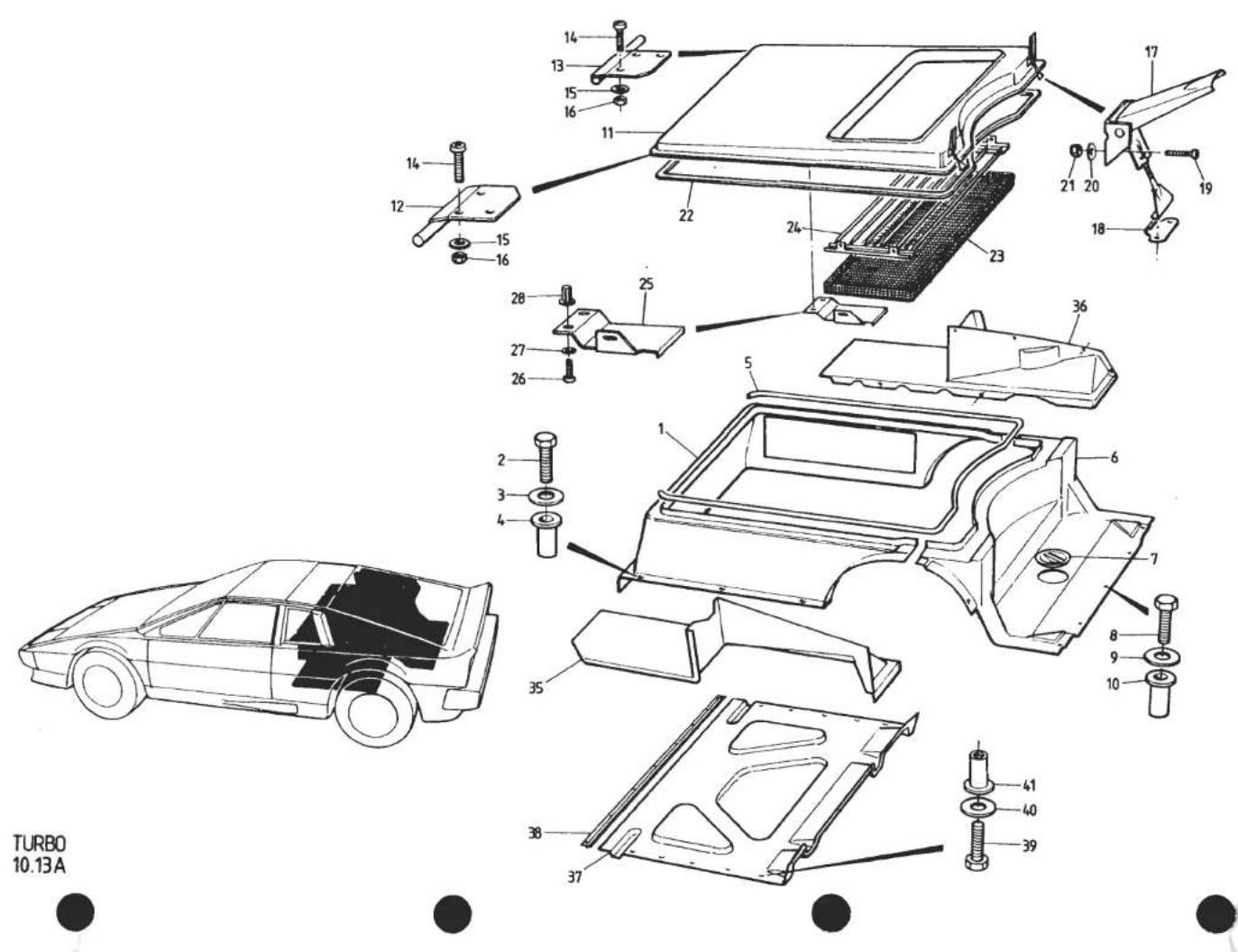
| ILLUSNO. | DESCRIPTION |  PART NUMBER PART NUMBER | QUANTITY | MAY 1991REMARKS | |
| ALL | |||||
| 10.13A | |||||
| 1 | Engine Bay Sidewall | A082B4286K | 1 | For Twist Lock Engine Lid Fasteners | |
| Engine Bay Sidewall | B082B4286K | 1 | For Overcentre Engine Lid Fasteners | ||
| Engine Bay Sidewall | C082B4286K | 1 | '87 M.Y. on | ||
| 2 | Screw, M6 x 25, Sidewall to Body | A075W5089Z | 8 | ||
| 3 | Washer, Flat, Sidewall to Body | A075W4013Z | 8 | ||
| 4 | Pulsert, M6, Sidewall to Body | A079W6156F | 8 | ||
| Setscrew, M6 x 25, Sidewall to Front Hinge Brkt. | A075W1031F | 2 | |||
| Washer, Large, O/D | A075W4016Z | 2 | |||
| Nut, Nyloc, M6 | A075W3009Z | 2 | |||
| 5 | Edge Finisher | C082U4775F | 3M | ||
| Rear Wall/Floor, Engine Bay | A082B4287K | 1 | For Twist Lock Engine Lid Fasteners | ||
| Rear Wall/Floor, Engine Bay | A082B4386K | 1 | Early Canadian Cars Only. Twist Lock Fasteners | ||
| 6 | Rear Wall/Floor, Engine Bay | B082B4287K | 1 | For Overcentre Engine Lid Fasteners | |
| Foam Strip, Rear Floor to Body | A082U6067F | 3m | |||
| Studplate, M6 x 20, Coilbox Fix | A082U5081F | 4 | |||
| Pop Rivet, Studplate Fix | A075W6090F | 8 | |||
| Washer, Pop Rivet | A075W4001F | 8 | |||
| 7 | Grommet, Gearbox Filler Access | X026B0371Z | 1 | ||
| 8 | Setscrew, M6 x 25, Floor to Body | A075W5089Z | 11 | ||
| 9 | Washer, Flat, Floor to Body | A085W4013Z | 11 | ||
| 10 | Pulsert, M6, Floor to Body | A079W6156F | 11 | ||
| Lid, Engine Bay | A082B4288K | 1 | For Twist Lock Engine Lid Fasteners | ||
| 11 | Lid, Engine Bay | B082B4288K | 1 | For Overcentre Engine Lid Fasteners | |
| Tongue, Engine Lid Front Hinge | A082B4280K | 2 | ) | ||
| Eye, Engine Lid Front Hinge | A082B4281K | 2 | ) | ||
| Setscrew, 10 UNF x ‡", Tongue/Eye | A075W1002F | 8 | ) | ||
| Washer | A075W4011F | 8 | )For Use With Lid A082B4288K | ||
| Nut, Nyloc, 10 UNF | A075W3000F | 8 | ) | ||
| Twist Lock Catch, Male, Engine Lid | B082B6051F | 4 | ) | ||
| Rubber Washer, Male Catch | B082B6052F | 4 | ) Turbo 10.13A | ||
| Twist Lock Catch, Female, Engine Lid | A082B6054F | 4 | ) Page 1 | ||
| Pop Rivet, Catch Fixing | A075W6071F | 8 | ) | ||
| d4p11 | |||||

| ILLUSNO. | DESCRIPTION | PART NUMBER | QUANTITY | MAY 1891REMARKS | |
| ALL | |||||
| 10.13A | |||||
| 12 | Hinge, LH, Engine Lid | A082U4769F | 1 | ) | |
| 13 | Hinge, RH, Engine Lid | A082U4770F | 1 | ) | |
| 14 | Screw, 10 UNF x 1⁄2", Hinge to Lid | A075W1002F | 6 | ) | |
| 15 | Washer, Flat, Hinge to Lid | A075W4011F | 6 | ) | |
| 16 | Nut, Nyloc, 10 UNF, Hinge to Lid | A075W3000F | 6 | ) | |
| 17 | Catch, Overcentre, Engine Lid | A079B6048F | 2 | )Chrome )For Use With Lid B082B4288K | |
| 18 | Striker, Overcentre Catch | A907E6303F | 2 | ) | |
| Catch, Overcentre, Engine Lid | A082B6095F | 2 | >Zinc ) | ||
| Striker, Overcentre, Catch | A082B6096F | 2 | > ) | ||
| 19 | Screw, 4BA, Catch/Striker Fix | A075W5049F | 8 | ) | |
| 20 | Washer, Flat, Catch/Striker Fix | A075W4001F | 8 | ) | |
| 21 | Nut, 4BA, Catch/Striker Fix | A079W3057F | 8 | ) | |
| Rivet, Zinc Striker Fix | A075W6090Z | 4 | |||
| 22 | Foam Seal, Engine Lid | A082U6065V | 3M | ||
| 23 | Mesh, Engine Lid Aperture | A082B4259K | 1 | ||
| 24 | Slat Assembly, Engine Lid Aperture | B082B4262J | 1 | ||
| Screw, Mesh and Slat Fixing | A075W5015Z | 10 | |||
| Spire Nut, Mesh and Slat Fixing | A075W6013Z | 10 | |||
| 25 | Water Shield, Engine Lid Aperture | A082B4338K | 1 | ||
| 26 | Screw, M6 x 12, Water Shield Fix | A075W1027Z | 2 | ||
| 27 | Washer, Shakeproof, Water Shield Fix | A075W4046Z | 2 | ||
| 28 | Jacknut, M6, Water Shield Fix | A075W3031Z | 2 | ||
| 35 | Trim Panel, Rear 1/4, LH | A082B4289K | 1 | NOT 'Glass Roof' >Including | |
| Trim Panel, Rear 1/4, LH | B082B4289K | 1 | 'Glass Roof' >Carpet | ||
| 36 | Trim Panel, Rear 1/4, RH | A082B4290K | 1 | Dry Sump Only > | |
| Trim Panel, Rear 1/4, RH | B082B4290K | 1 | Wet Sump. NOT 'Glass Roof' >For Carpet | ||
| Trim Panel, Rear 1/4, RH | C082B4290K | 1 | 'Glass Roof' >See 15.24A | ||
| Clip Bracket, Trim Panel to T/Gate Aperture | A082B4304K | 8 | ) | ||
| Pop Rivet, Brkt. to Panel | A075W6092Z | 16 | ) | ||
| Screw, Brkt. to Body | A075W5028Z | 8 | ) | ||
| Spire Nut, Brkt. to Body | A075W6014Z | 8 | )Fixings Replaced by Later Set | ||
| Screw, Panel to Engine Bay | A075W5037Z | 4 | ) | ||
| Washer, Flat, Panel to Engine Bay | A075W4000Z | 4 | ) | ||
| Spire Nut, Panel to Engine Bay | A075W6016Z | 4 | ) | ||
| d4p12 | Turbo 10.13APage 2 | ||||

| ILLUSNO. | DESCRIPTION | PART NUMBER | QUANTITY | MAY 1991REMARKS | |
| ALL | |||||
| 10.13A | |||||
| 37 | Spire Clip 'U' Nut, Trim Panel to Body | A082W6255F | 4 | R/B Shorter Undertray B082B4292K | |
| Spire Nut, Flat, Trim Panel to Body | A075W6013Z | 6 | |||
| Spire Nut, Trim Panel to Engine Bay | A075W6016Z | 4 | |||
| Screw, Panel to Body & Engine Bay | A075W5028Z | 14 | |||
| Setscrew, M5 x 20, Panel Rear to Engine Bay | A075W1025F | 2 | |||
| Jacknut, M5, Panel Rear to Eng. Bay | A076W3043F | 2 | |||
| Washer, Flat, Panel to Engine Bay | A075W4000Z | 6 | |||
| Undertray, Engine Bay | A082B4292K | 1 | |||
| Undertray, Engine Bay | B082B4292K | 1 | |||
| Undertray, Engine Bay | A082B4559K | 1 | |||
| 38 | Retaining Strip, Undertray Front | A082U4748K | 1 | ||
| Pop Rivet, Retainer to Body | A075W6089Z | 8 | |||
| 39 | Setscrew, M6 x 20, Undertray Fixing | A075W1030Z | 12 | ||
| 40 | Washer, Flat, Undertray Fixing | A075W4013Z | 12 | ||
| 41 | Pulsert, M6, Undertray Fixing | A079W6156F | 12 | ||
| d4p13 | Turbo 10.13APage 3 | ||||

TURBO
10.15A


| ILLUSNO. | DESCRIPTION |  PART NUMBER PART NUMBER | QUANTITY | MAY 1991REMARKS | |
| ALL | |||||
| 10.15A | |||||
| 1 | Door Shell, LH | A079B4185J | 1 | Prior Change Point * | |
| Door Shell, LH, RHD | A082B4586J | 1 | > From Change Point * | ||
| Door Shell, LH, LHD | A082B4588J | 1 | > | ||
| Door Shell, RH | A079B4186J | 1 | Prior Change Point * | ||
| Door Shell, RH, RHD | A082B4585J | 1 | > From Change Point * | ||
| Door Shell, RH, LHD | A082B4587J | 1 | > | ||
| 3 | Door Beam, LH | L079U4109K | 1 | ||
| Door Beam, RH | L079U4110K | 1 | * Change Point VIN 82 D 213782 - 0606 | ||
| 4 | Setscrew, M8 x 20, Door Rear to Beam | A075W1038Z | 4 | ||
| 5 | Washer, Large O/D, " " " " | A075W4021Z | 4 | ||
| 6 | Washer, Spacing, Door Rear to Beam | A075W4003Z | A/R | If Fitted | |
| 7 | Setscrew, M6 x 16, Door Front to Beam | A075W1028Z | 4 | ||
| 8 | Washer, Large O/D, Door Front to Beam | A075W4017Z | 4 | ||
| 9 | Fixing Plate, M6, Door Front to Beam | A079U4329K | 4 | ||
| 10 | Washer, Spacing, Shutline Adjust | A075W4022Z | A/R | If Fitted | |
| 12 | Hinge Post, Door, LH | D079U4405K | 1 | In Body 'A' Post | |
| Hinge Post, Door, RH | D079U4404K | 1 | In Body 'A' Post | ||
| Reinforcing Bracket, Hinge Post to Sill | A079U4409K | 2 | ) | ||
| Setscrew, M8 x 16, Bracket to Post | A075W1036F | 4 | ) | ||
| Washer, Plain, Bracket to Post | A075W4020F | 4 | ) | ||
| Washer, Spring, Bracket to Post | A075W4036F | 4 | )If Fitted | ||
| Tapping Plate, Bracket to Sill | A079U4410F | 2 | ) | ||
| Setscrew, M8 x 20, Bracket to Sill | A075W1038F | 4 | ) | ||
| Washer, Plain, Bracket to Sill | A075W4020F | 4 | ) | ||
| Washer, Spring, Bracket to Sill | A075W4036F | 4 | ) | ||
| 25 | Hinge Bracket, Upper, LH | H079U4087F | 1 | ||
| Hinge Bracket, Upper, RH | H079U4088F | 1 | |||
| 26 | Hinge Bracket, Lower | G079U4089F | 2 | ||
| 27 | Clamp Plate, Door Hinge | E079U4340F | 4 | ||
| 28 | Shim, 18 swg, Hinge to Body | C079U4090F | 4 | ||
| 29 | Shim, 18 swg, Hinge to Body | C079U4092F | A/R | Slotted | |
| Shim, 12 swg, Hinge to Body | C079U4091F | A/R | Slotted | ||
| 30 | Shim, Abrasive, Hinge to Body | B079U4094F | 4 | ||
| 31 | Nut, Nyloc, 1" UNF, Hinge to Body | A079W3056F | 4 | ||
| 32 | Tie Rod, Upper to Lower Hinge | A079U4326F | 2 | ||
| d4p14 | |||||

TURBO
10.15A


| ILLUS NO. | DESCRIPTION |  PART NUMBER PART NUMBER | QUANTITY |  REMARKS REMARKS | |
| ALL | |||||
| 10.15A | |||||
| 33 | Washer, Tie Rod to Hinge | A075W4020F | 4 | ||
| 34 | Nut, Nyloc, M8, Tie Rod to Hinge | A075W3010Z | 4 | ||
| 35 | Pivot Bush, Door Beam | C079U4189F | 4 | ||
| 36 | Pivot Pin, Door Beam | A079U4558F | 2 | ||
| 37 | Nut, Nyloc, M12, Pivot Pin | A075W3012F | 4 | ||
| Check Strap, LH | B075U0455J | 1 | ) | ||
| Check Strap, RH | B075U0456J | 1 | ) | ||
| Bolt, M8 x 45, Strap to Hinge Brkt. | A075W2040F | 2 | ) | ||
| Nut, Nyloc, M8, Strap to Hinge | A075W3010F | 2 | ) | ||
| Guide Assy. Check Strap Slider, LH | A075U0709W | 1 | )Earlier Type Check Strap With Coil | ||
| Guide Assy. Check Strap Slider, RH | A075U0708W | 1 | )Spring Activated Catch | ||
| Setscrew, M6 x 12, Guide to Bracket | A075W1027F | 4 | ) | ||
| Washer, Shakeproof, Guide to Bracket | A075W4046F | 4 | ) | ||
| Nut, M6, Guide to Bracket | A075W3020F | 4 | ) | ||
| 40 | Check Strap, inc. Spring, LH | A089U1517F | 1 | > | |
| Check Strap, inc. Spring, RH | A089U1516F | 1 | > | ||
| 41 | Spring, Door Check, LH | A089U1515F | 1 | > | |
| Spring, Door Check, RH | A089U1514F | 1 | > | ||
| 42 | Guide, Check Strap | A089U1518F | 2 | >Later Type Check Strap With Spring | |
| 43 | Setscrew, M6 x 30, Guide to Brkt. | A075W2028Z | 2 | >Wire Catch | |
| 44 | Washer, Plain | A075W4015F | 2 | > | |
| 45 | Nut, Nyloc, M6, Guide to Brkt. | A075W3009F | 2 | > | |
| 46 | Bolt, M8 x 45, Strap to Hinge | A075W2040F | 2 | > | |
| 47 | Nut, Nyloc, M8, Strap to Hinge | A075W3010F | 2 | > | |
| 50 | Bracket, Check Strap Guide to Beam, LH | E079U4191K | 1 | ||
| Bracket, Check Strap Guide to Beam, RH | E079U4258K | 1 | |||
| 51 | Bracket, Window Motor Mounting, LH | B079U4205F | 1 | ||
| Bracket, Window Motor Mounting, RH | B079U4126F | 1 | |||
| 52 | Studplate, M6, Bracket to Door Beam | B079U4011F | 6 | ||
| 53 | Nut, Nyloc, M6, Bracket to Door Beam | A075W3009F | 6 | ||
| Turbo 10.15APage 2 | |||||
| d4p15 | |||||

| ILLUSNO. | DESCRIPTION |  PART NUMBER PART NUMBER | QUANTITY | MAY 1991REMARKS | |
| ALL | |||||
| 10.17A | |||||
| 1 | Exterior Door Handle Set (Black) | B079U4634F | 1 | Comprises LH & RH Door Handles,Federal Cubby Box Lock & KeysComprises LH & RH Door Handles & Keys | |
| Exterior Door Handle Set (Silver & Black) | B075U0705W | 1 | |||
| Door Handle, Exterior, RH, (Black) | B079U4630F | 1 | |||
| Door Handle, Exterior, RH, (Silver & Black) | B075U6018Z | 1 | |||
| Door Handle, Exterior, LH, (Black) | B079U4631F | 1 | |||
| Door Handle, Exterior, LH, (Silver & Black) | B075U6019Z | 1 | |||
| 2 | Clamp Bracket, Handle to Door | A079U4661K | 2 | ||
| 3 | Nut, 10 UNF, Handle to Clamp | A075W3000F | 4 | ||
| Washer, 3/16", Handle to Clamp | A075W4000F | 4 | |||
| 4 | Door Handle, Interior, RH | B075U1076F | 1 | ||
| Door Handle, Interior, LH | B075U1075F | 1 | |||
| 7 | Tapping Plate, Door Handle to Door | A075U4061F | 2 | ||
| 8 | Screw, 10 UNF x 3/4", Handle to Door | A075W5061F | 6 | R/B A076W5062F | |
| Screw, 10 UNF x 1", Handle to Door | A076W5062F | 6 | |||
| 9 | Washer, Handle to Door | A075W4016F | 12 | ||
| 10 | Bezel, Door Handle | X054B6059F | 4 | ||
| 15 | Latch Mechanism, Door Lock, RH | A079U4628F | 1 | ||
| Latch Mechanism, Door Lock, LH | A079U4629F | 1 | |||
| 16 | Plate, Latch to Door Beam | A079U4616F | 2 | ||
| 23 | Bolt, M6 x 45, Latch to Beam | A075W7004Z | 8 | ||
| 24 | Nut, Nyloc, M6, Latch to Beam | A075W3009Z | 8 | ||
| 25 | Trunnion, Rods to Latch | A079U4620F | 6 | ||
| 26 | Circlip, Latch Trunnions | A079U6059F | 6 | ||
| 27 | Clip, Rod End, Ext. Release to Latch | A079W6153F | 2 | ||
| 28 | Clip, Rod End, Exterior Handle | A075U6033Z | 4 | ||
| 29 | Bracket, Rod Guide | A079U4255K | 2 | ||
| 30 | Guide Clip, Interior Handle Rods | A075J6027Z | 4 | ||
| Pop Rivet, Guide Bracket to Door | A075W6071Z | 4 | |||
| Washer, Pop Rivet | A075W4001Z | 4 | |||
| d4p17 | Turbo 10.17APage 1 | ||||
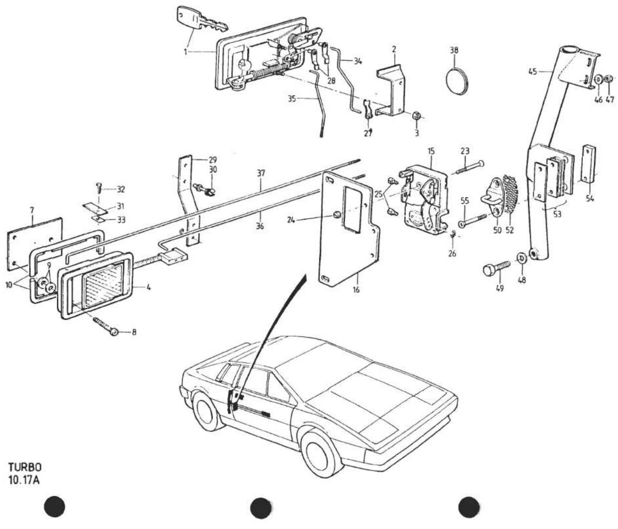
| ILLUSNO. | DESCRIPTION | PART NUMBER | QUANTITY | MAY 1991REMARKS | |
| ALL | |||||
| 10.17A | |||||
| 31 | Plate, Interior Lock Rod Retaining | A079U4337K | 2 | R/B B079U4626F | |
| 32 | Screw, Plate to Door | A075W5016F | 2 | ||
| 33 | Spire Nut, Plate to Door | A075W6013F | 2 | ||
| 34 | Rod, Exterior Release to Latch, RH | B079U4624F | 1 | ||
| Rod, Exterior Release to Latch, LH | B079U4625F | 1 | |||
| 35 | Rod, Exterior Lock to Latch, RH | A079U4622F | 1 | ||
| Rod, Exterior Lock to Latch, LH | B079U4623F | 1 | |||
| 36 | Rod, Interior Release to Latch | A079U4621F | 2 | ||
| Rod, Interior Lock to Latch, LH | B079U4627F | 1 | |||
| 37 | Rod, Interior Lock to Latch | B079U4626F | 2 | ||
| 38 | Grommet, Blanking, Lock Rod Access | X054J6005Z | 2 | ||
| 45 | Striker Post, RH | E079U4382F | 1 | ||
| Striker Post, LH | E079U4381F | 1 | |||
| 46 | Washer, Large O/D, Striker Post Top | A075W4021F | 4 | ||
| 47 | Nut, Nyloc, M8, Striker Post Top | A075W3010F | 4 | ||
| 48 | Washer, 12mm | A075W4071F | 2 | ||
| 49 | Setscrew, M12 x 30, Striker Post Bottom | A079W1058F | 2 | ||
| 50 | Striker Plate, Door Latch | A075U6022F | 2 | ||
| Spacer, 3mm, Striker to Body | A082U5003F | A/R | |||
| Spacer, 1.5mm, Striker to Body | A082U5002F | A/R | |||
| Abrasive Washer, Striker to Body | A075U0656Z | 2 | R/B Friction Plate A082U5004F | ||
| 52 | Friction Plate, Striker to Body | A082U5004F | 2 | ||
| 53 | Shim, 1.2mm, Striker Post to Body | B079U4486F | A/R | ||
| Shim, 3mm, Striker Post to Body | B079U4394F | A/R | |||
| 54 | Tapping Plate, Door Latch Striker | B075U0333F | 2 | ||
| 55 | Screw, M6 x 35, Striker Fixing | A082W7035F | 4 | ||
| d4p18 | Turbo 10.17APage 2 | ||||
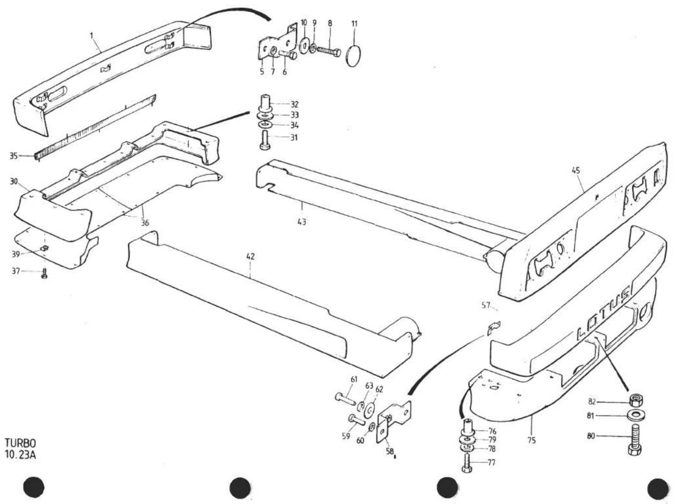
| ILLUSNO. | DESCRIPTION |  PART NUMBER PART NUMBER | QUANTITY | MAY1951REMARKS | |
| ALL | |||||
| 10.23A | |||||
| 1 | Front Bumper, GRP, Inc. Brkts. | A082B4240J | 1 | With Linear Diffusion PatternSide/Turn Lamps | |
| Front Bumper, GRP, Inc. Brkts. | A082B4533K | 1 | With Circular Diffusion PatternSide/Turn Lamps | ||
| 5 | Front Bumper, RRIM | A082B4428F | 1 | Prior '85 M.Y. R/B A082B460LJ (S/B 1986/0) | |
| Front Bumper, RRIM | A082B460LJ | 1 | '86 M.Y. on, with Lucas Side/Turn Lamps | ||
| Front Bumper, RRIM | B082B460LJ | 1 | '86 M.Y. on, with Cobo Side/Turn Lamps | ||
| Bracket, GRP Bumper Mtg. | C079U4135K | 5 | ) | ||
| 6 | Setscrew, Bracket to GRP Bumper | A075W1006Z | 10 | ) | |
| 7 | Washer, Spring, Bracket to GRP Bumper | A075W4035Z | 10 | )Use with GRP Bumpers | |
| 8 | Setscrew, M8 x 25, GRP Bumper to Body | A075W1039Z | 5 | )A082B4240/4533 | |
| 9 | Washer, Spring, GRP Bumper to Body | A075W4036Z | 5 | ) | |
| 10 | Washer, Large O/D, GRP Bumper to Body | A075W4003Z | 5 | ) | |
| 11 | Grommet, GRP Bumper Bolt Access (In Pod Well) | X054J6005Z | 4 | ) | |
| Setscrew, M8 x 25, Bumper Centre Fixing | A075W1039Z | 2 | > | ||
| Nut, Nyloc, M8, Bumper Centre Fixing | A075W3010Z | 2 | > | ||
| Washer, Flat, Bumper Centre Fixing | A075W4020Z | 4 | >Use With RRIM Bumper | ||
| Stud, 'Bighead' M6 x 20, Outboard Fixing | A085B6078F | 4 | >A082B4428F | ||
| Washer, Flat, Bumper Outboard Fixing | A075W4011Z | 4 | > | ||
| Nut, Nyloc, M6, Bumper Outboard Fixing | A075W3009Z | 4 | > | ||
| Setscrew, M8 x 25, Bumper Centre Fixing | A075W1039Z | 2 | ) | ||
| Washer, Flat, Bumper Centre Fixing | A075W4003Z | 4 | ) | ||
| Nut, Nyloc, M8, Bumper Centre Fixing | A075W3010Z | 2 | )Use with RRIM Bumper | ||
| Shim Plate, Bumper Outboard Fixing | A082B4603F | 2 | )A/B082B460LJ | ||
| Stud, M6 x 30, Bumper Outboard Fixing | A082U6082F | 4 | ) | ||
| Washer, Flat, Bumper Outboard Fixing | A075W4017Z | 4 | ) | ||
| Washer, Spring, Bumper Outboard Fixing | A075W4035Z | 4 | ) | ||
| Nut, Plain, M6, Bumper Outboard Fixing | A075W3020Z | 4 | ) | ||
| 30 | Spoiler, Front | A082B4236K | 1 | Prior '87 M.Y. | |
| Spoiler, Front | A082B4605K | 1 | '87 M.Y. on | ||
| 31 | Setscrew, M8 x 25, Spoiler To Body | A075W1039Z | 6 | ||
| 32 | Pulsert, M8, Spoiler to Body | A075W6155F | 6 | Turbo 10.23APage 1 | |
| d4pl9 | |||||

| ILLUS NO. | DESCRIPTION |  PART NUMBER PART NUMBER | QUANTITY |   | |
| ALL | |||||
| 10.23A | |||||
| 33 | Washer, Flat, Spoiler to Body | A075W4003Z | 6 | ||
| 34 | Washer, Spring, Spoiler to Body | A075W4036Z | 6 | ||
| Spire Bolt, Spoiler to Rad. Duct | A079W6166F | 5 | |||
| Spire Nut, Spoiler to Rad. Duct | A079W6165F | 5 | |||
| Washer, 6mm, Spoiler to Rad. Duct | A075W4015Z | 5 | |||
| 35 | Grille, Radiator Air Intake | A079U4544F | 1 | Prior '87 M.Y.'87 M.Y. on | |
| Grille, Radiator Air Intake | B082U5108F | 1 | |||
| Nut, Nyloc, Intake Grille Fix | A075W3000F | 5 | |||
| Washer, 5mm, Grille Fix | A075W4009F | 5 | |||
| 36 | Undershield, Front (Pair) | A082B4275K | 1 | Used With 306mm Rad. Duct Stays | |
| Undershield, Front (Pair) | A082B4492K | 1 | Used With 266 & 286mm Rad. Duct Stays | ||
| Spire Bolt, Undershield Fixing | A079W6166Z | 12 | ) | ||
| Washer, Spire Bolt | A075W4015Z | 12 | ) | ||
| Spire Nut, 'J' Type | A079W6165F | 7 | )Used With Undershield A082B4275K | ||
| Spire Nut, Flat | A079W6164F | 5 | ) | ||
| 37 | Screw, s/t, Undershield to Spoiler | A075W5043Z | 14 | > | |
| Screw, s/t, Undershield to Rad. Duct | A075W5041Z | 6 | >Used With Undershield A082B4492K | ||
| Washer, Undershield Fix | A075W4009Z | 20 | > | ||
| 39 | Spire Nut, Undershield Fix | A075W6016Z | 20 | > | |
| 42 | Sill, LH | C082B4239K | 1 | ||
| 43 | Sill, RH | C082B4238K | 1 | ||
| 45 | Spoiler, Rear | A082B4235K | 1 | Prior '87 M.Y.'87 M.Y. on | |
| Spoiler, Rear | A082B4654K | 1 | |||
| Pulsert, M6, Spoiler Fixing | A079W6156F | 10 | |||
| Setscrew, M6 x 25, Spoiler Fixing | A075W1031Z | 10 | |||
| Washer, Large O/D, Spoiler Fixing | A075W4017Z | 10 | |||
| Washer, Shakeproof, Spoiler Fixing | A075W4046Z | 10 | |||
| Screw, s/t, Spoiler Fixing | A075W5039Z | 8 | |||
| Spire Nut, Spoiler Fixing | A075W6016Z | 8 | |||
| 55 | Foam Strip, Spoiler Seal | A082U6067F | 3m | Turbo 10.23APage 2 | |
| d4p20 | |||||

| ILLUS NO. | DESCRIPTION |  PART NUMBER PART NUMBER | QUANTITY | MAY 1004REMARKS | |
| ALL | |||||
| 57 | Rear Bumper (GRP) Inc. Brkts. | A082B4345J | 1 | ||
| 58 | Bracket, GRP Bumper Mounting | C079U4135K | 6 | ||
| 59 | Setscrew, Bracket to GRP Bumper | A075W1006Z | 12 | ||
| 60 | Washer, Spring, Bracket to GRP Bumper | A075W4035Z | 10 | ||
| 61 | Setscrew, M8 x 25, Bumper to Body | A075W1039Z | 6 | ||
| 62 | Washer, Flat, Bumper to Body | A075W4003Z | 6 | ||
| 63 | Washer, Spring, Bumper to Body | A075W4036Z | 6 | ||
| Seal, Neoprene, Bumper to Body | B075U6054V | 2.2m | |||
| 75 | Rear Valance | A082B4464K | 1 | ||
| 76 | Pulsert, M8, Valance to Body | A079W6155F | 4 | ||
| 77 | Setscrew, M8 x 25, Valance to Body | A075W1039Z | 4 | ||
| 78 | Washer, Spring, Valance to Body | A075W4036Z | 4 | ||
| 79 | Washer, Flat, Valance to Body | A075W4002Z | 4 | ||
| 80 | Setscrew, M8 x 20, Valance to Bumper | A075W1038Z | 3 | ||
| 81 | Washer, Flat, Valance to Bumper | A075W4020Z | 6 | ||
| 82 | Nut, Nyloc, M8, Valance to Bumper | A075W3010Z | 3 | ||


| ILLUS NO. | DESCRIPTION |  PART NUMBER PART NUMBER | QUANTITY | REMARKS | |
| ALL | |||||
| 11.01A | |||||
| "Betaseal" Screen Fitting KitComprises:Betaseal 71904 in 300cc CartridgeGlass Primer Applicator BottleGlass Primer Applicator Head and Felt PadGlass Primer, Black, 84132-11Wipe Cleaner No. 4Piano Wire 0.6mm x 120cmSpecial Cleaning PaperSpacing Blocks 10 x 14 x 20mm | A075B6158J | A/R | Used for Windscreen and Rear Bulkhead Glass Fitment | ||
| 1 | |||||
| 1 | |||||
| 1 | |||||
| 1 | |||||
| 1 | |||||
| 1 | |||||
| 1 | |||||
| 4 | |||||
| "Solbit", Thermo-Electric Sealer, 9.5mm | A075B6121V | A/R | Replaces 8mm Solbit. Used on Door 1/4 Light, Rear 1/4 Light, Drop Glass and Tailgate Glass | ||
| "Solbit" PrimerWindscreen, TintedWindscreen, Clear | A075B6012ZA079U4023FA079U4014F | A/R | |||
| 1 | |||||
| 1 | |||||
| 1 | |||||
| 8 | |||||
| 1 | |||||
| Spacer, 4mm, Screen to BodyFinisher, Windscreen Top | A075U0588FB079U4048F | 1 | |||
| 1 | |||||
| Finisher, Windscreen, RH | A079U4050F | 1 | |||
| 1 | |||||
| Finisher, Windscreen, LH | A079U4049F | 1 | |||
| 2 | |||||
| Finisher Clip, Windscreen Top Corner | A079U4051F | 1.5m | |||
| Black Strip, 1 3/4" Screen Bottom | A082U6072V | 1 | |||
| Glass, Door 1/4 Light, RH, Tinted | A079U4026F | 1 | |||
| Glass, Door 1/4 Light, RH, Clear | A079U4018F | 1 | |||
| Glass, Door 1/4 Light, LH, Tinted | A079U4027F | 1 | |||
| Glass, Door 1/4 Light, LH, Clear | A079U4017F | 1 | |||
| Drop Glass, Door, RH, Tinted | A079U4028F | 1 | R/B A082U5034F | ||
| Drop Glass, Door, RH, Tinted | A082U5034F | 1 | |||
| Drop Glass, Door, RH, Clear | A079U4018F | 1 | |||
| Drop Glass, Door, LH, Tinted | A079U4029F | 1 | R/B A082U5035F | ||
| Drop Glass, Door, LH, Tinted | A082U5035F | 1 | |||
| Drop Glass, Door, LH, Clear | A079U4019F | 1 | |||
| Finisher, Door Top, External, RH | F079U4316F | 1 | Turbo 11.01APage 1 | ||
| d4p22 | |||||

| ILLUSNO. | DESCRIPTION |  PART NUMBER PART NUMBER | QUANTITY | MAY 1591REMARKS | |
| ALL | |||||
| 11.01A | |||||
| 12 | Finisher, Door Top, External LH | F079U4315F | 1 | ||
| Nut, Plain, 4BA, Finisher Fixing | A075W3057F | 6 | |||
| Washer, Flat, Finisher Fixing | A075W4001F | 6 | |||
| 13 | Weatherstrip, Door Glass, External | C079U4434F | 2 | ||
| Backing Strip, Weatherstrip/Finisher | D079U4438K | 2 | |||
| Pop Rivet, Weatherstrip/Finisher | A075W6071F | 26 | |||
| Finisher/Weatherstrip Assy. RH | A079U4576J | 1 | |||
| Finisher/Weatherstrip Assy. LH | A079U4577J | 1 | |||
| 14 | Seal, Drop Glass, Internal | A079U4175K | 2 | )Clip On, Prior VIN* | |
| 15 | Seal, Door 1/4 Light, Internal | A079U4176K | 2 | ) | |
| Clip, Seal, to Door Trim Channel | A075W6054Z | 16 | ) | ||
| Seal, Drop Glass, & 1/4 Light, Internal | A089V6166V | 2m | ]Stick On, From VIN* | ||
| 16 | Door Weatherstrip | A079U4197F | 2 | ||
| Secondary Door Seal (Wedge) | A082U4870F | 2 | *VIN 82 D 2431 | ||
| 20 | Glass, Rear 1/4 Light, RH, Tinted | A079U4550F | 1 | 82 - 0721 | |
| Glass, Rear 1/4 Light, RH, Clear | A079U4548F | 1 | |||
| 21 | Glass, Rear 1/4 Light, LH, Tinted | A079U4551F | 1 | ||
| Glass, Rear 1/4 Light, LH, Clear | A079U4599F | 1 | |||
| 22 | Spacer, 4mm, Glass to Body | A075U0588F | 8 | ||
| 23 | Trim, ABS, Rear 1/4 Glass, RH | B079U4570K | 1 | ||
| 24 | Trim, ABS, Rear 1/4 Glass, LH | B079U4569K | 1 | ||
| 25 | Sill Finisher, Rear 1/4 Glass, RH | B079U4572F | 1 | ||
| 26 | Sill Finisher, Rear 1/4 Glass, LH | B079U4571F | 1 | ||
| 27 | Nut, 10 UNF, Finisher Fixing | A075W3013F | 4 | ||
| 28 | Washer, Finisher Fixing | A075W4017F | 4 | ||
| 35 | Glass, Rear Bulkhead | A079U4032F | 1 | ||
| 36 | Spacer, Glass to Surround | A075U0588F | 6 | ||
| 37 | Surround, Bulkhead Glass Mounting | B079B4037K | 1 | Without 'Glass Roof' | |
| Surround, Bulkhead Glass Mounting | A082B4498K | 1 | With 'Glass Roof' | ||
| Foam Strip, Surround to Body | A036B6213V | 3m | |||
| 38 | Screw, 1⁄2", Surround to Body | A075W5014Z | 9 | ||
| 39 | Screw, 3/4", Surround to Body | A075W5028Z | 5 | Turbo 11.01APage 2 | |
| d4p23 | |||||

| ILLUS NO. | DESCRIPTION |  PART NUMBER PART NUMBER | QUANTITY | MAY 1991REMARKS | |
| ALL | |||||
| 11.01A | |||||
| 40 | Glass, Tailgate, Heated | A082U4669F | 1 | ||
| Glass, Tailgate, Unheated | A082U4668F | 1 | |||
| 41 | Spacer, 4mm, Glass to Tailgate | A075U0588Z | 4 | ||
| 42 | Surround, Tailgate Glass | A082U4717F | 1 | ||
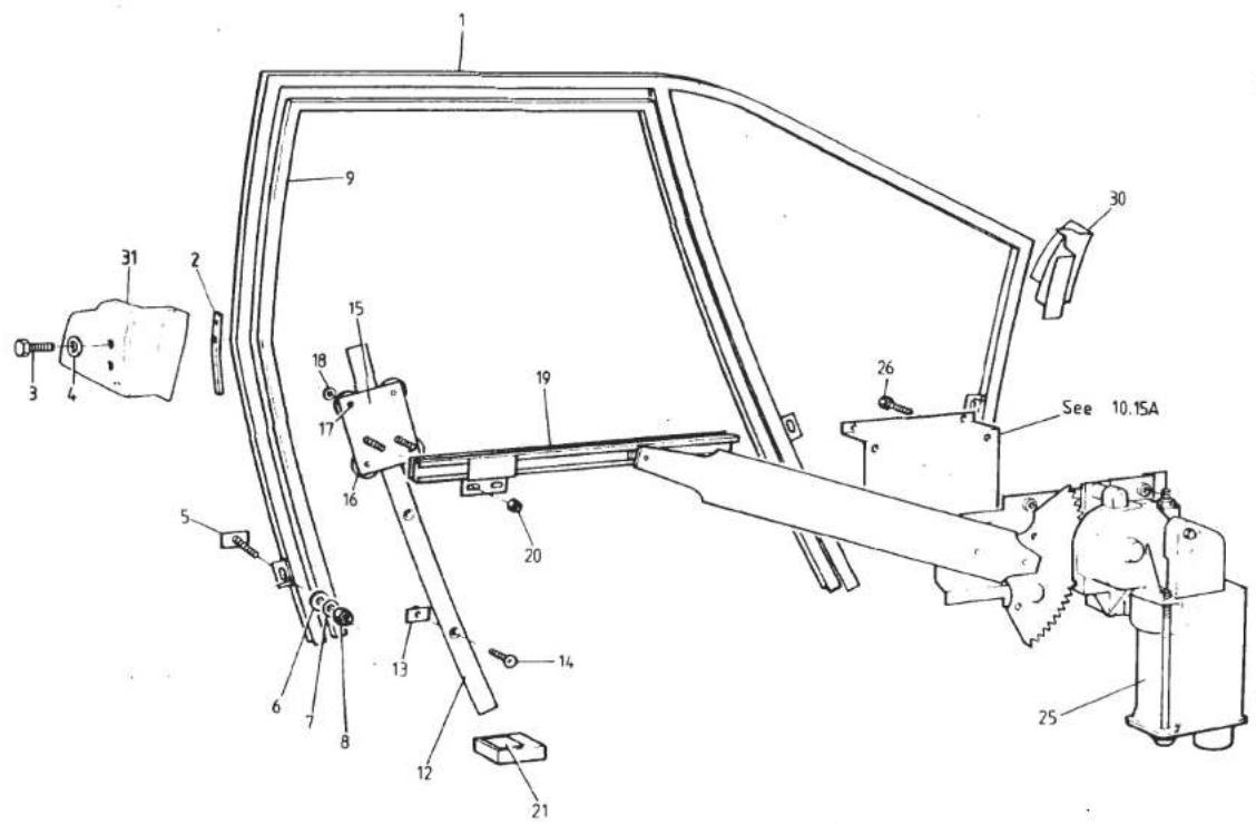
| ILLUSNO. | DESCRIPTION | PART NUMBER | QUANTITY | REMARKS | |
| ALL | |||||
| 11.05A | |||||
| 1 | Glass Roof | C082U4968F | 1 | ||
| 2 | Plinth, Tongue to Roof Glass | A082U4978F | 2 | ||
| 3 | Tapping Plate, Tongue Plinth | A082U6100F | 2 | ||
| 4 | Sealing Ring, Tapping Plate | A082U6103F | 2 | ||
| 5 | Screw, Plinth to Tapping Plate | A082W5097F | 2 | ||
| 6 | Washer, Plinth to Tapping Plate | A075W4000Z | 2 | ||
| 7 | Tongue, Roof Glass Front | A082U6101F | 2 | ||
| 8 | Screw, 10 UNF, Tongue to Plinth | A075W5058Z | 4 | ||
| 9 | Washer, Flat, Tongue to Plinth | A075W4000Z | 4 | ||
| 10 | Washer, Shakeproof, Tongue to Plinth | A075W4043Z | 4 | ||
| 13 | Slot Recess, LH, Roof Aperture Front | A082U6097F | 1 | ||
| Slot Recess, RH, Roof Aperture Front | A082U6098F | 1 | |||
| 14 | Gasket, Slot Recess to Body | A082U6099F | 2 | ||
| Bracket, Anti-rattle, Glass Roof | A082U5771F | 2 | If Fitted | ||
| 15 | Screw, Slot Recess to Body | A082W5115F | 4 | ||
| 16 | Washer, Slot Recess to Body | A075W4000Z | 4 | ||
| Washer, Slot Recess to Body | A075W4036Z | 4 | |||
| 17 | Catch Handle Assy. Roof Glass Rear | A082U6095F | 2 | ||
| 18 | Sliding Pin Assy. Catch Handle | B082U6096F | 2 | ||
| 18A | Screw, M4 x 10, Sliding Pin Assy. to Brkt. | A075W5079F | 4 | ||
| 19 | Washer, Sliding Pin Assy. to Brkt. | A075W4062F | 4 | ||
| 20 | Mounting Bracket, Sliding Pin/Body | C082U4974F | 2 | R/B D082U4974F | |
| Mounting Bracket, Sliding Pin/Body | D082U4974F | 2 | With Roof Abutment Buffer | ||
| Buffer, Rubber, Roof Abutment | X046B6113Z | 2 | Used With Bracket D082U4974F | ||
| 25 | Shim, Mounting Bracket to Body | A082U4975F | A/R | ||
| 26 | Screw, M6 x 16, Brkt. to Body | A075W1028Z | 8 | ||
| 27 | Washer, Bracket to Body | A075W4013Z | 8 | ||
| 30 | Recess Moulding, Catch Bracket, LH | A082U4987K | 1 | ||
| Recess Moulding, Catch Bracket, RH | A082U4988K | 1 | |||
| 31 | Screw, Moulding Fix | A075W5028Z | 4 | ||
| 32 | Spire Nut, Moulding Fix | A075W6014Z | 4 | ||
| 33 | Seal, Roof Glass to Body | A082U6123F | 3m | ||
| 35 | Bag, Roof Glass Protection | A082V7289J | 1 | Turbo 11.05A | |
| d4p26 | |||||
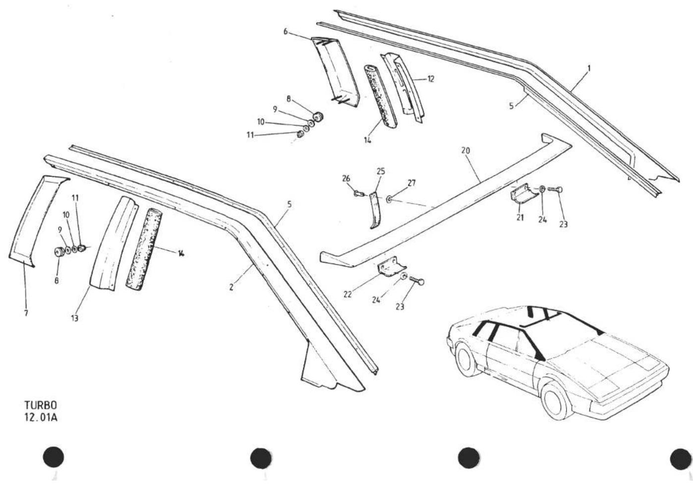
| ILLUSNO. | DESCRIPTION |  PART NUMBER PART NUMBER | QUANTITY | MAY 1991REMARKS | |
| ALL | |||||
| 12.01A | Capping Rail, LH | A079B4011K | 1 | With ABS Lower 'A' Post Finisher | |
| Capping Rail, LH | A082B4455K | 1 | With Integral Lower 'A' Post Finisher | ||
| Capping Rail, RH | A079B4012K | 1 | With ABS Lower 'A' Post Finisher | ||
| 2 | Capping Rail, RH | A082B4454K | 1 | With Integral Lower 'A' Post Finisher | |
| Pop Rivet, Capping Rail to Body | A075W6066Z | 14 | |||
| 3 | Finisher, 'A' Post Lower, LH ABS | A079U4165K | 1 | Used With Capping Rail A079B4011K | |
| 4 | Finisher, 'A' Post Lower, RH ABS | A079U4166K | 1 | Used With Capping Rail A079B4012K | |
| Pop Rivet, Finisher Fixing | A075W6090Z | 2 | |||
| Drive Fastener, Black | A079W6159F | 2 | |||
| 5 | Finisher Strip, Capping Rail to Body | B079U4010F | 2 | ||
| Pop Rivet, Finisher to Body | A075W6071Z | 22 | |||
| 6 | Air Scoop, LH, Engine Bay Ventilation | A079B4127K | 1 | ||
| 7 | Air Scoop, RH, Engine Air Intake | A079B4126K | 1 | ||
| Grille, LH, Air Scoop | A082U5117K | 1 | ) '87 M.Y. on) | ||
| Grille, RH, Air Scoop | A082U5118K | 1 | |||
| 8 | Grommet, Air Scoop to Body | A075U6058Z | 8 | ||
| 9 | Rubber Washer, Air Scoop Fix | A036L6019Z | 8 | ||
| 10 | Washer, Flat | A075W4000Z | 8 | ||
| 11 | Nut, Nyloc, 10 UNF | A075W3000Z | 8 | ||
| 12 | Finisher, 'B' Post, LH | B079B4035K | 1 | ||
| 13 | Finisher, 'B' Post, RH | B079B4036K | 1 | ||
| Pop Rivet, Finisher Fix | A075W6065Z | 16 | |||
| 14 | Foam Mesh, 'B' Post Ventilation | A082U5014K | 2 | ||
| 20 | Wind Deflector | C082B4512K | 1 | In Primer. 'Glass Roof' Models | |
| 21 | Retainer Tongue, LH, Wind Deflector | A082U4985F | 1 | ||
| 22 | Retainer Tongue, RH, Wind Deflector | A082U4986F | 1 | ||
| 23 | Screw, 10 UNF, Tongue to Deflector | A075W5059Z | 4 | ||
| 24 | Washer, Tongue to Deflector | A075W4000Z | 4 | ||
| 25 | Strap, Deflector Retaining | A082V7299J | 1 | ||
| 26 | Rivet, Strap to Deflector | A079W6195Z | 1 | ||
| 27 | Spring Clip, Strap Rivet | A075W6173F | 1 | ||
| Turbo 12.01A | |||||
| d4p27 | |||||

| ILLUSNO. | DESCRIPTION |  PART NUMBER PART NUMBER | QUANTITY | MAY 1091REMARKS | |
| ALL | |||||
| 12.05A | |||||
| 1 | Badge 'Styled by Giugiaro' | A079U4047F | 1/2 | Not Essex Turbo | |
| 2 | Badge, 'World Champion 1978' | A075U1160F | 1 | Where Fitted | |
| 3 | Bezel, World Champion Badge | A036B6341Z | 1 | Where Fitted | |
| 4 | Nose Badge, 'Old Style', Black/Silver | C036B0269F | 1 | ||
| " " " " Black/Gold | D036B0269F | 1 | R/B C079U4607F | ||
| " " " " Black/Gold | C079U4607F | 1 | |||
| 5 | Nose Badge, 'New Style', Green/Gold | A089U1550F | 1 | ||
| " " " " Black/Gold | A089U1610F | 1 | |||
| 6 | Rawlnut, 2BA, Nose Badge Fixing | B075W6029Z | 2 | >As Required | |
| Rawlnut, M5, Nose Badge Fixing | A075W6074F | 2 | > | ||
| 7 | Decal, 'Essex Lotus' | A082U4718F | 2 | ) | |
| 8 | Decal, Red 'X' | A082U4725F | 2 | ) | |
| 9 | Chrome Stripe, 12 mm Wide | A082U4719F | 12m | ) | |
| 10 | Chrome Stripe, 100 mm Wide | A082U4720F | 4.5m | )Essex Turbo Only | |
| 11 | Red Stripe, 55 mm Wide | A082U4724F | 12m | ) | |
| 12 | Decal, Commemorative, Numbered | A082U4723F | 2 | ) | |
| 13 | Decal, 'Essex', Chrome | A082U4722F | 1 | ) | |
| 14 | Decal, 'Turbo Esprit', Chrome | A082U4721F | 1 | ) | |
| Decal, 'Turbo Esprit', Red | A082U4692F | 3 | Total Height of Decal 160mm) | ||
| " " " Red | A082U4952F | 2 | " " " " 116mm) | ||
| " " " Gold | A082U4773F | 3 | " " " " 160mm) Prior to | ||
| " " " Gold | A082U4951F | 2 | " " " " 116mm) '87 M.Y. | ||
| " " " Black | A082U4833F | 3 | " " " " 160mm) | ||
| " " " Black | A082U4953F | 2 | " " " " 116mm) | ||
| " " " Silver | A082U4984F | 2 | " " " " 116mm) | ||
| 14A | Decal, 'Turbo Esprit H.C.', Gold/Red | A082U5873F | 2 | ) | |
| " " " " Red/Silver | A082U5874F | 2 | ) | ||
| " " " " Blue/Silver | A082U5875F | 2 | )'87 M.Y. on (First Colour - Outline | ||
| " " " " Gold/Black | A082U5876F | 2 | ) Second Colour - Infill) | ||
| Decal, 'Lotus', Red | A089U1771F | 2 | |||
| " " Gold | A089U1770F | 2 | |||
| " " Blue | A089U1772F | 2 | Turbo 12.05A | ||
| " " Silver | A089U1773F | 2 | Page 1 | ||
| d4p28 | |||||

| ILLUSNO. | DESCRIPTION | PART NUMBER | QUANTITY | MAY 1991REMARKS | |
| ALL | |||||
| 12.05A | |||||
| 15 | Single Stripe, 30 mm Wide, Red" " " " Gold" " " " " Black" " " " " Silver | A082U4867VA082U4868VA082U4869VA082U4884V | 10m10m10m10m12m12m12m12m12m12m2m8m10m10m2 | > | Prior '85 M.Y. |
| 16 | Pin Stripe, 3 mm Wide, Red" " " " " Gold" " " " " Black" " " " " Silver | A089U1699VA089U1530VA089U1529VA089U1769V | 12m12m12m12m12m12m12m12m12m12m12m12m12m12m12m12m12m12m12m12m12m12m12m12m12m12m12m12m12m12m12m12m12m12m | ] | '85 & '86 M.Y. |
| 17 | Black Tape, 8 mm Wide, Spoiler/Bumper | A089U1699VA089U1530VA089U1768V | 12m12m12m12m12m12m12m12m12m12m12m12m12m12m12m12m12m12m12m12m12m12m12m12m12m12m12m12m12m12m12m12m1 | } | '87 M.Y. on |
| 20 | Finisher Strip, Waistband ('Square' Profile) | B076U6005V | 8m10m10m10m10m10m10m10m10m10m10m10m10m10m10m10m10m10m10m10m10m10m10m10m10m10m10m10m10m10m10m10m10m10m10 | Prior to '85 M.Y. | Prior to '86 M.Y. |
| 21 | Finisher Strip, Waistband ('Rounded' Profile) | A082U5105VC079U4485F | 2 | '86 M.Y. Prior to VIN* | * VIN 82 D 2360 |
| 22 | Carrier, Waistband Finisher to Door | A079W5004FA075W6092Z | 18182.6m160cc40cc | '86 M.Y. on From VIN* | 82 - 0691 |
| Screw, s/t, Carrier to Door | A079W5004FA075W6092Z | 182.6m160cc40cc | |||
| Pop Rivet, Carrier to Door | A089U6063VA075U6088V | ||||
| Double Sided Tape, Carrier to Door | A075U6089V | ||||
| Adhesive, Part A, Waistband Finisher | |||||
| Adhesive, Part B, Waistband Finisher | |||||
| Turbo 12.05APage 2 | |||||
| d4p29 | |||||

TURBO
12.09A


| ILLUSNO. | DESCRIPTION |  PART NUMBER PART NUMBER | QUANTITY | MAY 1991REMARKS | |
| RHD | LHD | ||||
| 12.09A | |||||
| 1 | Door Mirror, RH, Convex | A079U6052F | 1 | 1 | ) |
| Door Mirror, RH, Flat | A079U6054F | 1 | 1 | Optional) | |
| Door Mirror, LH, Convex | A079U6051F | 1 | 1 | ) | |
| Door Mirror, LH, Flat | A079U6053F | 1 | 1 | Optional) | |
| 3 | Washer, Large O/D, Mirror to Door | A075W4017Z | 4 | 4 | ) Prior to VIN 82 D 2137 |
| 4 | Nut, Nyloc, M6, Mirror to Door | A075W3009Z | 4 | 4 | ) 82 - 0606 |
| Mirror Glass, Convex | A079U6064F | 2 | 2 | ) | |
| Mirror Glass, Flat | A079U6063F | 2 | 2 | ) | |
| Bezel, Mirror | A079U6071F | 2 | 2 | ) | |
| 10 | Door Mirror, RH, Less Mirror Glass | A082M6289F | 1 | > | |
| Door Mirror, RH, Less Mirror Glass | A082M6291F | 1 | > | ||
| Door Mirror, LH, Less Mirror Glass | A082M6290F | 1 | > | ||
| Door Mirror, LH, Less Mirror Glass | A082M6292F | 1 | > From VIN 82 D 2137 | ||
| Glass/Pad Assembly, Convex | A082M6295F | 2 | 2 | > 82 - 0606 | |
| 11 | Gasket, Door Mirror | A082M6305F | 2 | 2 | > |
| 12 | Washer, Mirror to Door | A075W4016Z | 4 | 4 | > |
| 13 | Nut, Nyloc, M6, Mirror to Door | A075W3009Z | 4 | 4 | > |
| Turbo 12.09A | |||||

| ILLUSNO. | DESCRIPTION | PART NUMBER | QUANTITY | MAY 1991REMARKS | |
| PRIOR'87 M.Y | '87 M.YON | ||||
| 13.03A | |||||
| 1 | Seat Frame | F079V4006F | 2 | ||
| 2 | Seat Frame, Reclining, RH | A082V5912F | 1 | ||
| Seat Frame, Reclining, LH | A082V5913F | 1 | |||
| 4 | Spring, Anti-Rattle | A083V6091F | 2 | ||
| 5 | Seat Reclining Mechanism, RH | A083V6066F | 1 | ||
| Seat Reclining Mechanism, LH | A083V6065F | 1 | |||
| 6 | Nut, Nyloc, MB | A075W3010F | 8 | ||
| 7 | Bolt, M8 x 60, Button Head | A082W7051F | 2 | ||
| 8 | Bolt, M8 x 30, Button Head | A082W7050F | 2 | ||
| 9 | Stud, Pawl Pivot | A083V2420F | 2 | ||
| 10 | Bolt, M8 x 20, Button Head | A075W7022F | 2 | ||
| 11 | Spacer | A082V5921F | 4 | ||
| 12 | Locking Plate, Tilt Pawl | A082V5923F | 2 | ||
| 13 | Pop Rivet, Locking Plate Fix | A075W6087F | 2 | ||
| 14 | Washer, Drive Plate Clamp | A089U6066F | 2 | ||
| 15 | Washer, Recline Mechanism Shaft | A089U6065F | 2 | ||
| 16 | Handwheel, Seat Recline | A083V6067F | 2 | ||
| 17 | Trim, Handwheel Centre | A083V6068F | 2 | ||
| 18 | Badge, Handwheel Trim Centre | A089U1553F | 2 | ||
| 19 | Seat Runner, Locking | A085V5721K | 2 | 2 | |
| 20 | Seat Runner, Non-Locking | A085V5722K | 2 | 2 | |
| 21 | Setscrew, Runner to Seat Frame | A075W1038Z | 8 | 8 | |
| 22 | Washer, Runner to Seat Frame | A075W4013Z | 16 | 16 | |
| 23 | Washer, Flat, Large O/D, Floor Underside | A075W4021F | 8 | 8 | |
| 24 | Nut, Nyloc, M8, Runner to Floor | A075W3010F | 8 | 8 | |
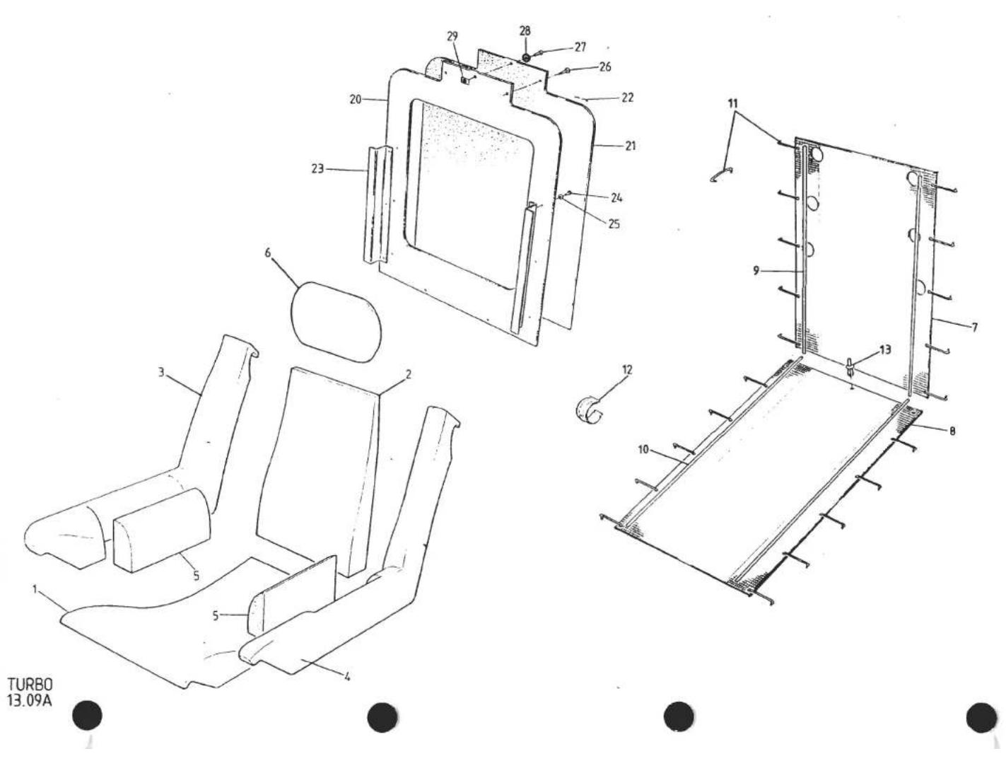
| ILLUS NO. | DESCRIPTION |  PART NUMBER PART NUMBER | QUANTITY | MAY 1991REMARKS | |
| ALL | |||||
| 13.09A | |||||
| 1 | Cushion Foam | A082V4777F | 2 | Quantities Are Per Car | |
| 2 | Backrest Foam | A082V4778F | 2 | ||
| 3 | Armrest Foam, RH | A085V5664K | 2 | )Fixed Seat. Prior '87 M.Y.) | |
| 4 | Armrest Foam, LH | A085V5665K | 2 | ||
| Armrest Foam, RH | A082V7352P | 2 | >Reclining Seat. '87 M.Y. on > | ||
| Armrest Foam, LH | A082V7353P | 2 | |||
| 5 | Insert, Armrest Foam | A085V5666F | 4 | ||
| 6 | Headrest Foam | A082V4779F | 2 | ||
| 7 | Suspension Unit, Backrest | B085V5663F | 2 | ||
| 8 | Suspension Unit, Cushion | B085V5662F | 2 | ||
| 9 | Flexolator, Backrest, 520mm | A082V4782F | 4 | ||
| 10 | Flexolator, Cushion, 490mm | A082V4783F | 4 | ||
| 11 | Hogring, Flexolator to Suspension Unit | A075W6076F | 80 | ||
| 12 | Tube Clip, Trim to Frame | B079W6120F | 110 | ||
| 13 | Rivet, Rokut, Cushion Unit to Frame | A079W6195F | 6 | ||
| 20 | Backboard | E079V4130F | 2 | ||
| 21 | Foam, 3mm, Seat Backboard | A079V6010V | 1sq.m | ||
| 22 | Staple | A075W6100F | 100 | ||
| 23 | Bracket, Seat Backboard Fix | A079V4122K | 4 | ||
| 24 | Pop Rivet, Bracket to Backboard | A075W6090Z | 12 | ||
| 25 | Washer, Pop Rivet | A075W4001Z | 12 | ||
| 26 | Screw, Backboard to Seat Frame | A075W5028Z | 6 | ||
| 27 | Screw, Press Stud Fix | A075W5026Z | 4 | ||
| 28 | Press Stud, Headrest Collar Fix | A076W6111D | 4 | ||
| 29 | Spire Nut, Press Stud Fix | A075W6013Z | 4 | ||

| ILLUSNO. | DESCRIPTION |  PART NUMBER PART NUMBER | QUANTITY | MAY 1991REMARKS | |
| PRIOR'87 M.Y | '87 M.YON | ||||
| 13.11A | Trimmed Seat Assembly, Complete | 082V7174J* | 2 | Fixed Backrest.>Reclining.> | |
| Trimmed Seat Assembly, Complete, RH | 082V7362J* | 1 | |||
| 2 | Trimmed Seat Assembly, Complete, LH | 082V7363J* | 1 | ||
| 4 | Trim Cover, Seat LH Flank | 082V7179J* | 2 | ) | |
| 5 | Trim Cover, Seat Centre | 082V7178J* | 2 | )Early Cars With 3 - Piece Seat Trim) | |
| 6 | Trim Cover, Seat, RH Flank | 082V7177J* | 2 | ||
| 7 | Trim Cover, Seat, Complete | 082V7180J* | 2 | ||
| 9 | Trim Cover, Seat, Complete, LH | 082V7367J* | 1 | ||
| Trim Cover, Seat, Complete, RH | 082V7366J* | 1 | |||
| 10 | Collar, Seat Head Restraint | 082V7183J* | 2 | ||
| 11 | Trim Cover, Seat Head Restraint | 082V7184J* | 2 | ||
| 12 | Trim Cover, Seat Head Restraint, Removeable | 082V7370J* | 2 | ||
| 13 | Trim Cover, Head Restraint Frame | 082V7379J* | 2 | ||
| 14 | Seat Backboard, Trimmed | 082V7185J* | 2 | ||
| Seat Backboard, Trimmed | 082V7382J* | 2 | |||
| *Prefix Trim Part Numbers With:A - All Leather (State Smooth or Ruched)B - All ClothF - Leather & Cloth (State Smooth or Ruched)Also Specify or Supply Sample of Colourand Vehicle Identification Number (VIN)Turbo 13.11A | |||||
| d4p34 | |||||

| ILLUSNO. | DESCRIPTION |  PART NUMBER PART NUMBER | QUANTITY | MAY 1991REMARKS | |
| ALL | |||||
| 13.27A | Seat Belt Assembly | B085V5730F | 2 | R/B A085V7166F | |
| Seat Belt Assembly | A085V7166F | 2 | R/B B085V7166F | ||
| Seat Belt Assembly | B085V7166F | 2 | |||
| 3 | Finisher, Seat Belt Bulkhead Slot | B075V0612K | 2 | ||
| 4 | Button, Slot Finisher Fixing | A075W6041F | 4 | ||
| 5 | Cover, Seat Belt Reel, ABS | A082U4740K | 2 | ||
| 7 | Screw, Belt Reel Cover | A075W5028Z | 8 | ||
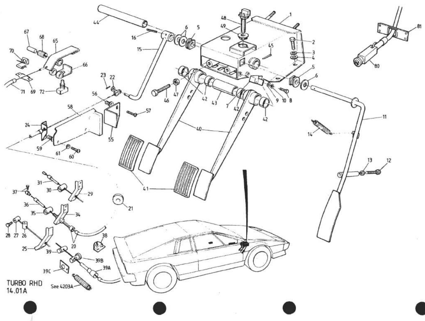
| ILLUSNO. | DESCRIPTION | PART NUMBER | QUANTITY | MAY 1991REMARKS | |
| LHD | |||||
| 14.01B | This Page LHD Only. For RHD See 14.01A | ||||
| 1 | Pedal Box (Uses Threaded Stop Switch) | B079J4059J | 1 | R/B D079J4059J with stop switch A089M6019F, Bush A089M6020F & mtng brkt A082J4169KWith integral top mounted stop switch brkt, R/B D079J4059J with brkt A082J4169KUses separate rear mounted stop switch brkt | |
| Pedal Box (Uses Push & Twist Stop Switch) | C079J4059J | 1 | |||
| Pedal Box (Uses Push & Twist Stop Switch) | D079J4059J | 1 | |||
| 2 | Setscrew, M8 x 25, Pedal Box to Chassis | A075W1039Z | 4 | ||
| 3 | Washer, Spring, Pedal Box to Chassis | A075W4048Z | 4 | ||
| 4 | Washer, Flat, Pedal Box to Chassis | A075W4020Z | 4 | ||
| 5 | Bearing, Throttle Pedal Pivot | A075J6005F | 2 | ||
| 6 | Washer, Throttle Pedal Pivot | A075W4005F | 3 | ||
| 7 | Bracket, Throttle Pedal Upstop | G079J4017F | 1 | ||
| 8 | Setscrew, M6 x 16, Upstop to P/Box | A075W1028F | 2 | ||
| 9 | Washer, Flat, Upstop Fix | A075W4013F | 2 | ||
| Nut, Nyloc, M6, Upstop Fix | A075W3009F | 2 | With No Pedal Box WeldnutsWith Pedal Box Weldnuts | ||
| 10 | Washer, Shakeproof | A075W4046F | 2 | ||
| 11 | Throttle Pedal | A079J4062F | 1 | ||
| 12 | Split Pin, Throttle Pedal Retention | A075W6176F | 1 | ||
| 13 | Bolt, M8 x 60, Pedal Downstop | A079W1044F | 1 | ||
| 14 | Locknut, M8, Downstop | A075W3026F | 1 | ||
| 15 | Buffer, Pedal Downstop | X046B6113Z | 1 | ||
| 16 | Spring, Throttle Pedal Return | A075J6029F | 1 | ||
| 20 | Abutment Bracket, Throttle Downstop | A079J4057F | 1 | ||
| 21 | Setscrew, M6 x 16, Bracket Fix | A075W1028Z | 4 | ||
| 22 | Washer, Large O/D, Bracket Fix | A075W4017Z | 4 | ||
| 23 | Nut, Nyloc, M6, Bracket Fix | A075W3009Z | 4 | ||
| 30 | Throttle Cable, Inc. Adjuster | C079J4055F | 1 | ||
| 31 | Grommet, Throttle Cable | X050B6158Z | 1 | ||
| 32 | Clevis Pin, Cable to Pedal | A075W6030Z | 1 | ||
| 33 | Washer, Cable Clevis to Pedal | A075W4000Z | 1 | ||
| 34 | Split Pin, Clevis Retaining | A075W6005Z | 1 | ||
| 35 | Abutment, Throttle Cable | C079J4016K | 1 | ||
| Pop Rivet, Abutment to Body | A075W6090F | 2 | |||
| d4p39 | Turbo LHD 14.01BPage 1 | ||||

| ILLUSNO. | DESCRIPTION |  PART NUMBER PART NUMBER | QUANTITY | MAY 1991REMARKS | |
| RHD | |||||
| 14.01A | This Page RHD Only. For LHD See 14.01B | ||||
| Pedal Box (Uses Threaded Stop Switch) | B079J4059J | 1 | R/B D079J4059J with stop switch A089M6019F, Bush A089M6020F & mtg brkt A082J4169KWith integral top mounted stop switch brktR/B D079J4059J with brkt A082J4169KUses separate rear mounted stop switch brkt | ||
| 1 | Pedal Box (Uses Push & Twist Stop Switch) | C079J4059J | 1 | ||
| Pedal Box (Uses Push & Twist Stop Switch) | D079J4059J | 1 | |||
| 2 | Setscrew, M8 x 25, Pedal Box to Chassis | A075W1039Z | 4 | ||
| 3 | Washer, Spring, Pedal Box to Chassis | A075W4048Z | 4 | ||
| 4 | Washer, Flat, Pedal Box to Chassis | A075W4020Z | 4 | ||
| 5 | Bearing, Throttle Pedal Pivot | A075J6005F | 2 | ||
| 6 | Washer, Throttle Pedal Pivot | A075W4005F | 3 | ||
| 7 | Bracket, Throttle Pedal Upstop | G079J4017F | 1 | ||
| 8 | Setscrew, M6 x 16, Upstop to Pedal Box | A075W1028F | 2 | ||
| 9 | Washer, Flat, Upstop Fix | A075W4013F | 2 | ||
| Nut, Nyloc, M6, Upstop Fix | A075W3009F | 2 | With No Pedal Box WeldnutsWith Pedal Box WeldnutsR/B C079J4060F With Downstop | ||
| 10 | Washer, Shakeproof | A075W4046Z | 2 | ||
| Throttle Pedal | B079J4060F | 1 | |||
| 11 | Throttle Pedal, With Downstop | C079J4060F | 1 | ||
| 12 | Bolt, M8 x 45, Throttle Pedal Downstop | A075W1043Z | 1 | ||
| 13 | Nut, M8, Downstop Locknut | A075W3072F | 1 | ||
| 14 | Spring, Throttle Pedal Return | A075J6029F | 1 | ||
| 15 | Lever, Throttle | A079J4061F | 1 | ||
| 16 | Spirol Pin, M5 x 30, Lever to Pedal Shaft | A082W6235F | 1 | ||
| 20 | Throttle Cable, Inc. Adjuster | C079J4055F | 1 | ||
| 21 | Grommet, Throttle Cable | X050B6158Z | 1 | ||
| 22 | Washer, Cable Clevis to Lever | A075W4000Z | 1 | ||
| 23 | Split Pin, Cable Clevis to Lever | A075W6005Z | 1 | ||
| 24 | Abutment, Throttle Cable, Front | C079J4016K | 1 | ||
| Pop Rivet, Abutment to Body | A075W6090F | 2 | |||
| 25 | Bracket, Throttle Cable Abutment | C910E1535F | 1 | On Plenum B/Plate)With HairpinLess Clamp Screw )Type Carb.)Lever Return)SpringTurbo RHD 14.01APage 1 | |
| 26 | Trunnion Barrel, Carb. Throttle Lever | A050B6160F | 1 | ||
| 27 | Barrel, Solderless Nipple (Modify) | A074K6001Z | 1 | ||
| 28 | Screw, Solderless Nipple | B074K6002F | 1 | ||
| d4p36 | |||||

| ILLUSNO. | DESCRIPTION |  PART NUMBER PART NUMBER | QUANTITY | MAY 1991REMARKS | |
| RHD | |||||
| 14.01A | |||||
| 29 | Bracket, Throttle Cable Abutment | D910E1535F | 1 | This Page RHD Only. For LHD See 14.01B | |
| 30 | Trunnion Barrel, Carb. Throttle Lever | A082J4118F | 1 | )Used With Extension Type Carb. | |
| 31 | Spacer, Trunnion to Nipple | A082J4119F* | 1 | )Lever Return Spring, With S/Less | |
| Barrel, Solderless Niple | A074K6001Z* | 1 | )Nipple At Pedal End. Replace Parts | ||
| Screw, Solderless Nipple | B074K6002Z* | 1 | )Marked * With Parts Marked + And Fit | ||
| 34 | Bracket, Throttle Cable Abutment | D910E1535F | 1 | )S/Less Nipple At Carb. End. Refer To | |
| 35 | Trunnion Barrel, Carb. Throttle Lever | A082J4118F | 1 | )S/B 1985/08 | |
| 36 | Spacer Trunnion to Nipple | A082J4119F+ | 1 | >Used With Extension Type Carb. | |
| 37 | Solderless Nipple | A082J6096F+ | 1 | >Lever Return Spring, With S/Less | |
| Setscrew, Abutment Bracket to Plenum | A075W1027Z | 2 | >Nipple At Carb. End. | ||
| Washer, Spring, Abutment Bracket to Plenum | A075W4035Z | 2 | > | ||
| 38 | Anchor Bracket, Throttle Cable to Cam Cover | A912E1639F | 1 | ) | |
| Screw, Anchor Bracket to Cam Cover | A079W7011F | 2 | ) | ||
| 39 | Solderless Nipple, Throttle Cable | A050B6160F | 1 | ) | |
| 39A | Cable Extension | A079J4079F | 1 | )'87 M.Y. on | |
| 39B | Trunnion Barrel, Carb. Throttle Lever | A079J4077F | 1 | ) | |
| 39C | Spring Plate, Throttle Return Spring | A079J4078K | 1 | ) | |
| 40 | Pedal, Brake and Clutch | D079J4002F | 2 | Prior to '85 Model Year | |
| Pedal, Brake and Clutch | A082J4126F | 2 | '85 Model Year Onward | ||
| 41 | Pad, Brake & Clutch Pedals | A079J6001F | 2 | ||
| 42 | Pivot Bush, Brake & Clutch Pedals | A079J6025F | 4 | ||
| 43 | Spacer, Brake/Clutch Pedals | A079J4005F | 1 | ||
| 44 | Shaft, Brake and Clutch Pedal Pivot | B079J4003J | 1 | ||
| 45 | Split Pin, Pedal Shaft Retaining | A075W6008Z | 1 | ||
| 46 | Setscrew, M8 x 50, Brake/Clutch Upstop | A079W1044F | 2 | ||
| 47 | Locknut, M8, Brake/Clutch Upstop | A075W3026Z | 2 | '85 Model Year Onward | |
| Switch, Stop Light | X036M6154W | 1 | ) Thread & Nut Fixing | ||
| Locknut, Stop Switch | A050M6067Z | 1 | ) | ||
| d4p37 | Turbo RHD 14.01APage 2 | ||||

| ILLUS NO. | DESCRIPTION |  PART NUMBER PART NUMBER | QUANTITY | MAY 1991REMARKS | |
| RHD | |||||
| 14.01A | This Page RHD Only. For LHD See 14.01B | ||||
| 48 | Switch, Stop Light | A089M6019F | 1 | >Quickfit', Push and Twist | |
| 49 | Bush, Stop Switch Retentional | A089M6020F | 1 | > | |
| Bracket, Stop Light Switch Mounting | A082J4169K | 1 | Used with Pedal Box D079J4059J | ||
| 55 | Footrest, Left FootBrake/Clutch Upstop | A079J4074K | 1 | ||
| 56 | Jacknut, M5, Footrest Fixing | A076W3043F | 2 | ||
| 57 | Setscrew, M5 x 12, Footrest Fixing | A075W1021F | 2 | ||
| 58 | Cover, Footrest | B079J4075K | 1 | ||
| 59 | Jacknut, M6, Cover Fixing | A075W3034F | 2 | ||
| 60 | Setscrew, M6 x 12, Cover Fixing | A075W1027F | 2 | ||
| 61 | Washer, Shakeproof Cover Fixing | A075W4046F | 2 | ||
| 65 | Choke Lever | D079U4235F | 1 | ) | |
| 66 | Bracket, Choke Lever Mounting | F079U4260F | 1 | ) | |
| Pop Rivet, 1/8", Bracket Fix | A075W6090Z | 2 | ) | ||
| 67 | Pivot Pin, Choke Lever | A079U4261F | 1 | ) | |
| 68 | Bush 'Startol Ring', Choke Lever Pivot | A079U6019F | 1 | )With Tunnel Mounted Choke Control | |
| 69 | Bracket, Choke Cable Abutment | B079U4297F | 1 | ) | |
| 70 | Clip, Choke Cable Abutment | A075W6117F | 1 | ) | |
| 71 | Choke Cable | A079S4008F | 1 | ) | |
| 72 | Micro-Switch, Choke Warning | B075M6024F | 1 | ) | |
| 80 | Choke Cable (inc. Micro Switch) | A082S4101F | 1 | > | |
| 81 | Mounting Plate, Choke Cable to Fascia | C082U4927F | 1 | >With Fascia Mounted Choke Control | |
| Pop Rivet, Mounting Plate to Fascia | A075W6066F | 4 | >Prior to VIN 82 D 2402 | ||
| Clip, Choke Cable to Engine Bay Rear | A079W6124F | 1 | > 82 - 0708 | ||
| Choke Cable (inc. Micro Switch) | A089S0764F | 1 | ) | ||
| Mounting Plate, Choke Cable to Fascia | A082U5116F | 1 | )With Fascia Mounted Choke Control | ||
| Pop Rivet, Mounting Plate to Fascia | A075W6090Z | 4 | )From VIN 82 D 2402 | ||
| Washer, Pop Rivet | A075W4001Z | 4 | ) 82 - 0708 | ||
| Clip, Choke Cable to Plate | A089W6278F | 1 | ) | ||
| d4p38 | Turbo RHD 14.01APage 3 | ||||

| ILLUSNO. | DESCRIPTION |  PART NUMBER PART NUMBER | QUANTITY | MAY 195REMARKS | |
| LHD | |||||
| 14.01B | |||||
| This Page LHD Only. For RHD See 14.01A | |||||
| 40 | Bracket, Throttle Cable Abutment | C910E1535F | 1 | On Plenum B/Plate )With Hairpin Type | |
| 41 | Trunnion Barrel, Carb. Throttle Lever | A050B6160F | 1 | Less Clamp Screw )Carb. Lever Return | |
| 42 | Barrel, Solderless Nipple (modify) | A074K6001Z | 1 | )Spring | |
| 43 | Screw, Solderless Nipple | B074K6002F | 1 | ) | |
| 44 | Bracket, Throttle Cable Abutment | D910E1535F | 1 | )Used With Extension Type Carb.Lever | |
| 45 | Trunnion Barrel, Carb. Throttle Lever | A082J4118F | 1 | )Return Spring, With S/Less Nipple At | |
| 46 | Spacer, Trunnion to Nipple | A082J4119F* | 1 | )Pedal End. Replace Parts Marked * With | |
| Barrel, Solderless Nipple | A074K6001Z* | 1 | )Parts Marked + And Fit S/Less Nipple At | ||
| Screw, Solderless Nipple | B074K6002Z* | 1 | )Carb End. Refer To S/B 1985/08 | ||
| 49 | Bracket, Throttle Cable Abutment | D910E1535F | 1 | >Used With Extension Type Carb. Lever | |
| 50 | Trunnion Barrel, Carb. Throttle Lever | A082J4118F | 1 | >Return Spring, With S/Less Nipple At | |
| 51 | Spacer Trunnion to Nipple | A082J4119F+ | 1 | >Carb. End. | |
| 52 | Solderless Nipple | A082J6096F+ | 1 | > | |
| Setscrew, Abutment Bracket to Plenum | A075W1027Z | 2 | |||
| Washer, Spring, Abut. Brkt. to Plenum | A075W4035Z | 2 | |||
| 53 | Anchor Bracket, Throttle Cable to Cam Cover | A912E1639F | 1 | ) | |
| Screw, Anchor Bracket to Cam Cover | A079W7011F | 2 | ) | ||
| 54 | Solderless Nipple, Throttle Cable | A050B6160F | 1 | ) | |
| 54A | Cable Extension | A079J4079F | 1 | )'87 M.Y. on | |
| 54B | Trunnion Barrel, Carb. Throttle Lever | A079J4077F | 1 | ) | |
| 54C | Spring Plate, Throttle Return Spring | A079J4078K | 1 | ) | |
| 55 | Pedal, Clutch | A079J4051F | 1 | Prior to '85 Model Year | |
| Pedal, Clutch | A082J4125F | 1 | 1985 Model Year Onwards | ||
| 56 | Pedal, Brake | A079J4051F | 1 | Prior to '85 Model Year | |
| Pedal, Brake | A082J4125F | 1 | 1985 Model Year Onwards | ||
| 57 | Pad, Brake & Clutch Pedals | A079J6001F | 2 | ||
| 58 | Pivot Brush, Brake & Clutch Pedals | A079J6025F | 4 | ||
| 59 | Spacer, Brake/Clutch Pedals | A079J4005F | 1 | ||
| 60 | Shaft, Brake & Clutch Pedal Pivot | B079J4003J | 1 | ||
| 61 | Split Pin, Pedal Shaft Retaining | A075W6008Z | 1 | Turbo LHD 14.01B | |
| d4p40 | Page 2 | ||||

| ILLUSNO. | DESCRIPTION | PART NUMBER | QUANTITY | MAY 1991REMARKS | |
| LHD | |||||
| 14.01B | This Page LHD Only. For RHD See 14.01A | ||||
| 62 | Setscrew, M8 x 50, Brake/Clutch Upstop | A079W1044F | 2 | ||
| 63 | Locknut, M8, Brake/Clutch Upstop | A075W3026Z | 2 | ||
| Switch, Stop Light | X036M6154W | 1 | ) Thread & Nut Fitting | ||
| Locknut, Stop Switch | A050M6067Z | 1 | ) | ||
| 64 | Switch, Stop Light | A089M6019F | 1 | >Quickfit', Push & Twist | |
| 65 | Bush, Stop Switch Retention | A089M6020F | 1 | > | |
| Bracket, Stop Light Switch Mounting | A082J4169K | 1 | Used with Pedal Box D079J4059J | ||
| 70 | Choke Lever | D079U4235F | 1 | ) | |
| 71 | Bracket, Choke Lever Mounting | F079U4260F | 1 | ) | |
| Pop Rivet 1/8" Bracket Fix | A075W6090Z | 2 | ) | ||
| 72 | Pivot Pin, Choke Lever | A079U4261F | 1 | ) | |
| 73 | Bush, 'Startol Ring' Choke Lever Pivot | A079U6019F | 1 | )With Tunnel Mounted Choke Control | |
| 74 | Bracket, Choke Cable Abutment | B079U4297F | 1 | ) | |
| 75 | Clip, Choke Cable Abutment | A075W6117F | 1 | ) | |
| 76 | Choke Cable | A079S4008F | 1 | ) | |
| 77 | Micro-Switch, Choke Warning | B075M6024F | 1 | ) | |
| 80 | Choke Cable (inc. Micro Switch) | A082S4101F | 1 | > | |
| 81 | Mounting Plate, Choke Cable to Fascia | C082U4927F | 1 | >With Fascia Mounted Choke Control | |
| Pop Rivet, Mounting Plate to Fascia | A075W6066F | 4 | >Prior to VIN 82 D 2402 Outer Cable | ||
| Clip, Choke Cable to Engine Bay Rear | A079W6124F | 1 | > 82 - 0708 Length 3.0m | ||
| Choke Cable (inc. Micro Switch) | A089S0764F | 1 | ) | ||
| Mounting Plate, Choke Cable to Fascia | A082U5116F | 1 | )With Fascia Mounted Choke Control | ||
| Pop Rivet, Mounting Plate to Fascia | A075W6090Z | 4 | )From VIN 82 D 2402 Outer Cable | ||
| Washer, Pop Rivet | A075W4001Z | 4 | ) 82 - 0708 Length 2.7m | ||
| Clip, Choke Cable to Plate | A089W6278F | 1 | ) | ||
| Turbo LHD 14.01BPage 3 | |||||
| d4p41 | |||||

TURBO
14.05A

| ILLUSNO. | DESCRIPTION |  PART NUMBER PART NUMBER | QUANTITY | MAY 1991REMARKS | |
| RHD | LHD | ||||
| 14.05A | |||||
| 1 | Fascia, Trimmed | 082V5170J* | 1 | With Rectangular Centre Vents | |
| Fascia, Trimmed | 082V7188J* | 1 | With Round Centre Vents. No Choke Aperture | ||
| Fascia, Trimmed, Square Choke Cable Aperture | 082V7287J*† | 1 | )Round Centre Vents. Choke Cable Aperture | ||
| Fascia, Trimmed, 'D' Shape Cable Aperture | 082V7430J*† | 1 | ) | ||
| Fascia, Trimmed | 082V5171J* | 1 | With Rectangular Centre Vents | ||
| Fascia, Trimmed | 082V7190J* | 1 | With Round Centre Vents. No Choke Aperture | ||
| Fascia, Trimmed, Square Choke Cable Aperture | 082V7288J*† | 1 | )Round Centre Vents. Choke Cable Aperture | ||
| Fascia, Trimmed, 'D' Shape Cable Aperture | 082V7431J*† | 1 | ) | ||
| 3 | Jacknut, M6, Fascia Fixing | A075W3034Z | 4 | 4 | |
| 4 | Bracket, Fascia to 'A' Post | A079U4354K | 2 | 2 | |
| 5 | Trim Cover, Screen Landing | 082V5206K* | 1 | 1 | With Perforations for Concealed Speakers |
| Trim Cover, Screen Landing | 082V7217K* | 1 | 1 | Plain. Cut Speaker Apertures if Required | |
| 7 | Column Shroud, Top, Trimmed | 082V5185J* | 1 | 1 | |
| 8 | Column Shroud, Bottom, Trimmed | 082V5186J* | 1 | 1 | |
| 9 | Spire Nut, Column Shroud Fixing | A079W6024Z | 4 | 4 | |
| *Prefix Trim Part Numbers With: A - Leather (State Smooth or Ruched) B - Cloth (Brushed Velour) Also Specify or Supply Sample of Colour and Vehicle Identification Number (VIN) | |||||
| † Change Point: VIN 82 D 2402 82 - 0708 | |||||
| d4p77 | Turbo 14.05A | ||||
TURBO 14.07A

| ILLUS NO. | DESCRIPTION |  | QUANTITY | MAY 1931 | |
| ALL | REMARKS | ||||
| 14.07A | |||||
| 1 | Instrument Mounting Panel, Steel | B082U4734J | 1 | White Illumination | |
| Instrument Mounting Panel, Steel | C082U4734J | 1 | Green Illumination. R/B E082U4734J | ||
| Instrument Mounting Panel, Steel | E082U4734J | 1 | '87 M.Y. on | ||
| 2 | Bracket, Instrument Panel to Binnacle | A079U4354K | 1 | Prior to '87 M.Y. | |
| Bracket, Instrument Panel to Binnacle | A079U4393C | 2 | ) | ||
| Clip, Instrument Panel to Bracket | A075W6117F | 2 | )'87 M.Y. on | ||
| Screw, s/t, No. 6 x ‡", Panel Fix | A075W5012F | 7 | ) | ||
| Spire Nut, Panel Fix | A079W6024F | 7 | ) | ||
| 3 | Mask, Instrument Panel, ABS | B082U4664K | 1 | Prior to '87 M.Y. | |
| Mask, Instrument Panel, ABS | D082U4664K | 1 | '87 M.Y. on | ||
| 4 | Side Panel, Binnacle, RH, Steel | B082U4689K | 1 | ||
| 5 | Side Panel, Binnacle, LH, Steel | B082U4688K | 1 | ||
| 6 | Bracket, Fuel/Voltmeter Mounting | B082U4683C | 2 | ||
| 7 | Mask, Side Panel, RH, ABS | A082U4662K | 1 | ||
| 8 | Mask, Side Panel, LH, ABS | A082U4663K | 1 | ||
| d4p78 | Turbo 14.07A | ||||

TURBO
14.08A
| ILLUSNO. | DESCRIPTION |  PART NUMBER PART NUMBER | QUANTITY | MAY 1991REMARKS | |
| ALL | |||||
| 14.08A | |||||
| 1 | Centre Console, Trimmed, inc. Lever Gaiter | 082V5193J* | 1 | ) Fettle Radio Aperture as Required | |
| 2 | Blanking Panel, Trimmed, Radio Aperture | 082V523LJ* | 1 | ) Prior to VIN 82 D 2153 | |
| 4 | Light Box, Heater/A/C Controls | A082U4756J | 1 | ) 82 - 0609 | |
| 5 | Spacer, Heater/A/C Controls | A082B4216K | 1 | ) | |
| Clock Mounting Panel, (ABS) | A082U4753J | 1 | )> Essex Commemorative Only | ||
| Cassette Storage Bin, (ABS) | A082U4754J | 1 | )> | ||
| 10 | Centre Console, Trimmed, inc. Gaiter & Brkts. | 082V7192J* | 1 | > VIN 82 D 2153 to 2270 | |
| Blanking Panel, Trimmed, Radio Aperture | 082V523LJ* | 1 | > 82 - 0609 to 0622 | ||
| 12 | Bracket, Centre Console, Rear | A085V5723K | 1 | > | |
| 13 | Setscrew, M6 x 20, Console to Tunnel | A075W1030Z | 1 | > | |
| 14 | Washer, Flat, Console to Tunnel | A075W4015Z | 1 | > | |
| 15 | Rawlnut, M6, Console to Tunnel | A075W6140Z | 1 | > ]Alternatives | |
| Rawlnut, M6, 'Neoprene' Console to Tunnel | A082W6285F | 1 | > ] | ||
| 16 | Mounting Bracket & Light Box, Heater/A/CControls | A082U4918J | 1 | > | |
| 17 | Screw, Heater/A/C Bracket Fix | A075W5027Z | 4 | > | |
| Spire Nut, Top Fix | A075W6014Z | 2 | > | ||
| 18 | Edge Protector, 'Neoprene' | B075U6054V | 140mm | > | |
| 20 | Centre Console, Trimmed, inc. Gaiter & Brkts. | 082V727LJ* | 1 | ) From VIN 82 D 2271 | |
| 21 | Blanking Panel, Trimmed Radio Aperture | 082V7272J* | 1 | ) 82 - 0623 | |
| 22 | Fastener, Blanking Panel Fix | A079W6162F | 2 | ) | |
| 23 | Bracket, Centre Console, Rear | A085V5723K | 1 | ) | |
| Setscrew, M6 x 20, Console to Tunnel | A075W1030Z | 1 | ) | ||
| Washer, Flat, Console to Tunnel | A075W4015Z | 1 | ) | ||
| Rawlnut, M6, Console to Tunnel | A075W6140Z | 1 | ) | ||
| d6p20 |  Turbo 14.08APage 1 Turbo 14.08APage 1 | ||||

| ILLUS NO. | DESCRIPTION |  PART NUMBER PART NUMBER | QUANTITY | MAY 1991 REMARKS | |
| ALL | |||||
| 14.08A | |||||
| 27 | Mounting Bracket & Light Box, Heater/A/C Controls | ||||
| 28 | Screw, Bracket to Tunnel Top | A082U5062J | 1 | ) From VIN 82 D 2271) 82 - 0623 | |
| 29 | Washer, Flat, Console/Brkt. to Fascia | A075W5027Z | 2 | ||
| 30 | Wing Nut, Console/Brkt. to Fascia | A075W4009Z | 2 | ||
| Washer, Shakeproof, Console/Brkt. to Fascia | A082W3081F | 2 | |||
| A075W4086Z | 2 | ||||
| 35 | Gaiter, Gear Lever | A082V5196K | 1 | ||
| 36 | Retaining Ring, Gear Lever Gaiter | A085U4826K | 1 | ||
| 37 | Choke/Window Switch Panel, Trimmed | 082V5203J* | 1 | With Tunnel Mounted Choke Control | |
| Window Switch Panel, Trimmed | 082V7260J* | 1 | With Fascia Mounted Choke Control | ||
| * Prefix Trim Part Numbers With :A - Leather (State Smooth or Ruched)B - Cloth (Brushed Velour)Also Specify or Supply Sample ofColour and Vehicle IdentificationNumber (VIN) | |||||
| d6p21 | Turbo 14.08APage 2 | ||||

| ILLUSNO. | DESCRIPTION | PART NUMBER | QUANTITY | MAY 1991REMARKS | |
| ALL | |||||
| 1 | Instrument Binnacle, TrimmedFoam Binnacle, Interior, Anti-Rattle | 082V5182J*A079V6010V | 1A/R | ||
| 2 | Mounting Bracket, Binnacle to Fascia | A079U4527K | 1 | ||
| 3 | Setscrew, M6 x 18, Binnacle to Brkt. | A075W1029Z | 2 | ||
| 4 | Washer, Large O/D, Binnacle to Brkt. | A075W4017Z | 2 | ||
| 5 | Fascia Blanking Panel, Trimmed, RHD | 082V5233J* | 1 | ||
| Fascia Blanking Panel, Trimmed, LHD | 082V5173J* | 1 | |||
| *Prefix Trim Part Number With:A - LeatherB - Cloth (Brushed Velour)Also Specify or Supply Sample ofColour, and Vehicle IdentificationNumber (VIN) | |||||
| Turbo 14.10A | |||||
| d4p42 | |||||
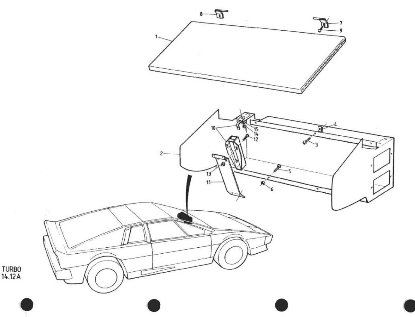
| ILLUS NO. | DESCRIPTION |  PART NUMBER PART NUMBER | QUANTITY | MAY 1991REMARKS | |
| ALL | |||||
| 14.12A | |||||
| 1 | Glove Box Lid, Trimmed | 082V5175J* | 1 | ||
| 2 | Glove Box Inner, RHD | C082V4790F | 1 | ||
| Glove Box Inner, LHD | B082V4791F | 1 | |||
| 3 | Screw, Glove Box Inner Top Edge Fix | A075W5027Z | 3 | ||
| 4 | Spire Nut, Glove Box Top Edge Fix | A075W6014Z | 3 | ||
| 5 | Screw, 10 UNF x 1⁄2", Glovebox to Fascia | A075W5059Z | 3 | ||
| 6 | Nut, Nyloc, 10 UNF " " " | 3 | |||
| 7 | Hinge, Glovebox Lid, RH | B079U4436F | 1 | ||
| 8 | Hinge, Glovebox Lid, LH | B079U4435F | 1 | ||
| 9 | Screw, Hinge to Fascia Beam | A075W5012F | 2 | ||
| 10 | Latch, Glovebox Lid | A082U6130F | 1 | ||
| 11 | Bracket, Latch to Fascia | B079U4374F | 1 | ||
| 12 | Screw, Latch to Bracket | A075W5049F | 2 | ||
| 13 | Nut, 4BA, Latch to Bracket | A075W3057F | 2 | ||
| 14 | Nut, Nyloc, 6BA, Striker to Lid | A079W3058W | 2 | ||
| 15 | Washer, Striker to Lid | A075W4000W | 2 | *Prefix Trim Part Numbers With:A - Leather (State Smooth or Ruched)B - Cloth (Brushed Velour)Also Specify or Supply Sample ofColour and Vehicle IdentificationNumber (VIN)Turbo 14.12A | |
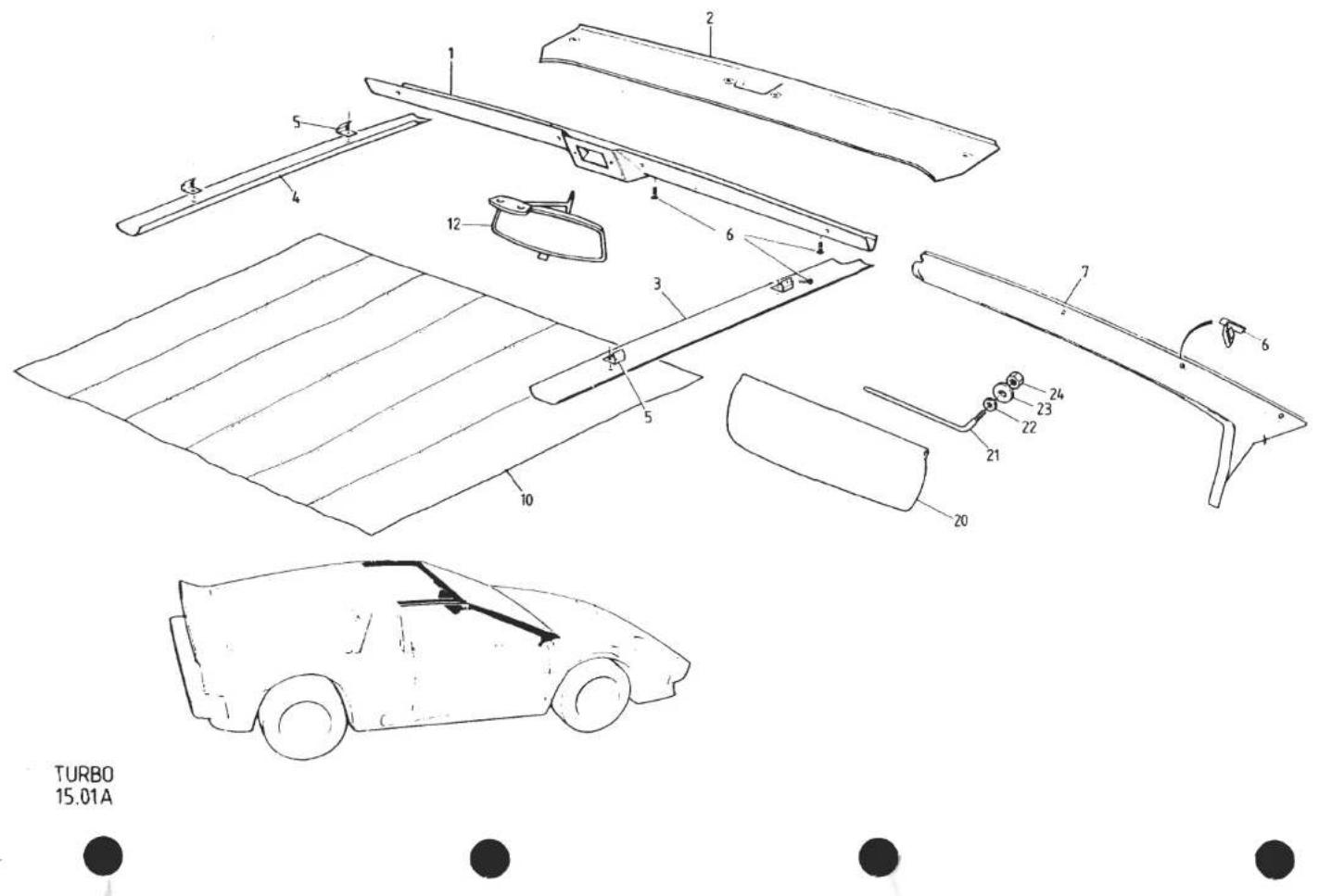
| ILLUS NO. | DESCRIPTION |  PART NUMBER PART NUMBER | QUANTITY | MAY 1991REMARKS | |
| FIXED ROOF | GLASS ROOF | ||||
| 15.01A | |||||
| Header Rail, Trimmed | A082V5227J† | 1 | No Clock - 'Essex' Cars Only | ||
| Header Rail, Trimmed | A079V4496J† | 1 | For 'Rocking Bar' Type Clock | ||
| 1 | Header Rail, Trimmed | A082V7198J† | 1 | For 'Pin Button' Type Clock | |
| 2 | Header Rail, Trimmed | A082V7200J† | 1 | For 'Pin Button' Type Clock | |
| Header Rail, Trimmed | A082V7286J† | 1 | For 'Rocking Bar' Type Clock | ||
| 3 | Cant Rail, Trimmed, RH | A079V4526K† | 1 | ||
| Cant Rail, Trimmed, RH, | A082V7202J† | 1 | |||
| 4 | Cant Rail, Trimmed, LH, | A079V4527J† | 1 | ||
| Cant Rail, Trimmed, LH, | A082V7203J† | 1 | |||
| 5 | Bracket, Cant Rail, Fixing | A082U4992K | 4 | 4 | |
| 6 | Screw, Header & Cant Rail Fixing | A075W4028Z | 6 | 6 | |
| 7 | 'A' Post Trimmed Panel, RH | A082V5190J | 1 | 'Essex' Cars Only | |
| 'A' Post Trimmed Panel, RH | 082V7206J* | 1 | 1 | ||
| 'A' Post Trimmed Panel, LH | A082V5189J | 1 | 'Essex' Cars Only | ||
| 'A' Post Trimmed Panel, LH | 082V7207J* | 1 | 1 | ||
| 8 | Clip 'A' Post Trim Fixing | A075W6062Z | 6 | 6 | |
| 10 | Headlining, | A079V4560J† | 1 | ||
| Mirror, Interior | A079U6012F | 1 | Stick On | ||
| 12 | Mirror, Interior | A079U6044F | 1 | 1 | Screw On |
| Screw, 2BA, Mirror to Header Rail | A079W5052F | 2 | 2 | ||
| Nut, Nyloc, 2BA, Mirror Fixing | A079W3001F | 2 | 2 | ||
| Washer, Mirror Fixing | A079W4011Z | 2 | 2 | ||
| 20 | Sun Visor, Drivers, RHD | A079V4800J† | 1 | 1 | |
| Sun Visor, Drivers, RHD, with 'Document Strap | A082V7380J† | 1 | 1 | ||
| Sun Visor, Drivers, LHD | A079V4803J† | 1 | 1 | ||
| Sun Visor, Drivers, LHD, with 'Document Strap | A082V7381J† | 1 | 1 | ||
| Sun Visor, Passenger, RHD | A079V4801J† | 1 | 1 | With Mirror | |
| Sun Visor, Passenger, LHD | A079V4802J† | 1 | 1 | With Mirror | |
| 21 | Swivel, Sun Visor | A079V4361F | 4 | 4 | *Prefix Trim Part Numbers With: |
| 22 | Washer, Sun Visor Swivel | A075W4015Z | 4 | 4 | A - Leather |
| 23 | Washer, Sun Visor Swivel | A075W4017Z | 4 | 4 | B - Cloth (Brushed Velour) |
| 24 | Nut, Nyloc, M6, Sun Visor Swivel | A075W3009Z | 4 | 4 | Also State or Supply Sample of Colour& Vehicle Identification Number (VIN) |
| d4p44 | † State or Supply Sample of ColourTurbo 15.01A | ||||

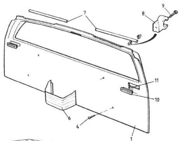
TURBO
15.11A


| ILLUS NO. | DESCRIPTION |  PART NUMBER PART NUMBER | QUANTITY | REMARKS | |
| FIXED ROOF | GLASS ROOF | ||||
| 15.11A | |||||
| 1 | Bulkhead Trimmed Panel | 082V5207J* | 1 | For Interior Lamp with Rocking Lens Switch | |
| Bulkhead Trimmed Panel | 082V7282J* | 1 | For Interior Lamp with Button Switch | ||
| Bulkhead Trimmed Panel | 082V7384J* | 1 | '87 M.Y. on | ||
| 2 | Bulkhead Trimmed Panel | 082V7215J* | 1 | For Interior Lamp with Rocking Lens Switch | |
| Bulkhead Trimmed Panel | 082V7283J* | 1 | For Interior Lamp with Button Switch | ||
| Bulkhead Trimmed Panel | 082V7385J* | 1 | '87 MY. on | ||
| 3 | Grille, Rear Bulkhead, Air Outlet | A082V4780F | 4 | ||
| 4 | Screw, Rear Bulkhead Trim Fixing | A075W5028Z | 4 | 4 | |
| 5 | Screw, Rear Bulkhead Top Fixing | A075W5028Z | 2 | ||
| Map Pocket, Trimmed | 082V5205J* | 1 | 1 | Prior to '87 M.Y. | |
| 6 | Map Pocket, Trimmed | 082V7372J* | 1 | 1 | '87 M.Y. on |
| 7 | Doweling, Bulkhead Trim Fixing | A079U6048F | 0.7m | ||
| 8 | Clip, Bulkhead Trim Doweling | A079W6183F | 8 | ||
| 9 | Screw, Clip to Bulkhead Trim | A079W5047F | 4 | ||
| Screw, Clip to Body | A075W5026Z | 4 | |||
| 10 | Slot Finisher, Seat Belt | B075V0612K | 2 | 2 | |
| 11 | Button, Slot Finisher Retaining | A075W6041F | 4 | 4 | *Prefix Trim Part Numbers With: A - Leather (State Smooth or Ruched) B - Cloth (Brushed Velour) Also State or Supply Sample of Colour & Vehicle Identification Number (VIN) |
| d4p46 | Turbo 15.11A | ||||
TURBO
15.13A


| ILLUSNO. | DESCRIPTION |  PART NUMBER PART NUMBER | QUANTITY | MAY 1991REMARKS | |
| RHD | LHD | ||||
| 15.13A | |||||
| Door Trim Panel, Trimmed, LH | 082V5210J* | 1 | No Ashtray. No Speaker) | ||
| Door Trim Panel, Trimmed, LH | 082V7219J* | 1 | No Ashtray. Speaker Perforations) | ||
| Door Trim Panel, Trimmed, LH | 082V7221J* | 1 | With Ashtray. No Speaker) | ||
| Door Trim Panel, Trimmed, LH | 082V5212J* | 1 | No Ashtray. No Speaker) | ||
| Door Trim Panel, Trimmed, LH | 082V5223J* | 1 | No Ashtray. Speaker Perforations) | ||
| Door Trim Panel, Trimmed, LH | 082V7225J* | 1 | With Ashtray. No Speaker) † | ||
| Door Trim Panel, Trimmed, RH | 082V5209J* | 1 | No Ashtray. No Speaker) | ||
| Door Trim Panel, Trimmed, RH | 082V7218J* | 1 | No Ashtray. Speaker Perforations) | ||
| Door Trim Panel, Trimmed, RH | 082V7220J* | 1 | With Ashtray. No Speaker) | ||
| Door Trim Panel, Trimmed, RH | 082V5211J* | 1 | No Ashtray. No Speaker) | ||
| Door Trim Panel, Trimmed, RH | 082V7222J* | 1 | No Ashtray. Speaker Perforations) | ||
| Door Trim Panel, Trimmed, RH | 082V7224J* | 1 | With Ashtray. No Speaker) | ||
| † Prior to VIN 82 D 213782 - 0606 | |||||
| Door Trim Panel, Trimmed, LH | 082V7275J* | 1 | > | ||
| Door Trim Panel, Trimmed, LH | 082V7277J* | 1 | > | ||
| Door Trim Panel, Trimmed, RH | 082V7276J* | 1 | > | ||
| Door Trim Panel, Trimmed, RH | 082V7278J* | 1 | > From VIN 82 D 2137> 82 - 0606 | ||
| Stud Plate, Mirror Switch Fixing | A082U5069F | 1 | 1 | > Prior to '87 M.Y. | |
| Bracket, Mirror Control Switch Mounting | A082U5066F | 1 | 1 | > | |
| Nut, Nyloc, M5, Bracket/Stud Plate | A075W3008Z | 3 | 3 | For Sill Mounted Ashtray, See 15.30A | |
| Prefix Trim Part Numbers With:A - All Leather (State Smooth or Ruched)B - All ClothF - Leather & Cloth (Brushed Velour)Also State or Supply Sample of ColourVehicle Identification Number (VIN)Turbo 15.13APage 1 | |||||
| d4p47 | |||||
TURBO 15.13A


| ILLUSNO. | DESCRIPTION |  PART NUMBER PART NUMBER | QUANTITY | MAY 1991REMARKS | |
| RHD | LHD | ||||
| 15.13A | |||||
| 1 | Door Trim Panel, Trimmed, LH | 082V7373J* | 1 | ) | |
| Door Trim Panel, Trimmed, LH | 082V7375J* | 1 | ) | ||
| Door Trim Panel, Trimmed, RH | 082V7374J* | 1 | ) | ||
| Door Trim Panel, Trimmed, RH | 082V7376J* | 1 | )'87 M.Y. on | ||
| Stud Plate, Mirror Switch Fixing | A082U5069F | 1 | 1 | ) | |
| Bracket, Mirror Control Switch Mounting | A082U5066F | 1 | 1 | ) | |
| Nut, Nyloc, M5, Bracket to Stud Plate | A075W3008Z | 3 | 3 | ) | |
| 2 | Flange, Window Weatherstrip Mounting | B079V4017F | 2 | 2 | For Clip on W/Strip,Inc. in Trimmed Door |
| Flange, Window Weatherstrip Mounting | C079V4017F | 2 | 2 | For Stick on W/Strip,Panel | |
| 4 | Ashtray Assembly (Chrome Frame) | 089V3883J* | 2 | 2 | Note.All Door Trim Panels Inc. Flange |
| Ashtray Assembly (Black Frame) | 089V4309J* | 2 | 2 | Suitable for 'Stick on' Type Weatherstrip | |
| 5 | Clamp Bracket, Ashtray | A083V2474F | 2 | 2 | A089V6166V (See 11.01 A) |
| 6 | Screw, Ashtray Fixing | A075W5028Z | 2 | 2 | |
| Door Pull Handle, Trimmed, LH | 082V5217J* | 1 | 1 | )Prior '87 M.Y. | |
| Door Pull Handle, Trimmed, RH | 082V5218J* | 1 | 1 | ) | |
| 10 | Door Pull Handle, Trimmed, LH | 082V7377J* | 1 | 1 | >'87 M.Y. on |
| Door Pull Handle, Trimmed, RH | 082V7378J* | > | |||
| 11 | Washer, Door Pull Handle Fix | A075W4015F | 4 | 4 | |
| 12 | Nut, Nyloc, M6, Handle Top Fix | A075W3009F | 2 | 2 | |
| Setscrew, M6 x 16, Handle Lower Fix | A075W1028F | 2 | 2 | For Female Threaded Handle | |
| 13 | Spacer, Handle Lower to Door | A082V5903K | 2 | 2 | ) |
| 14 | Nut, Nyloc, M6, Handle Lower Fix | A075W3009F | 2 | 2 | )For Handle With Stud |
| 15 | Screw, Door Trim Panel Fixing | A075W5028F | 4 | 4 | |
| 16 | Tapping Plate, Door Panel Screws | A079U4479F | 4 | 4 | |
| Pop Rivet, Tapping Plate to Door Shell | A075W6071F | 8 | 8 | For Sill Mounted Ashtray, See 15.30A | |
| Prefix Trim Part Numbers With: | |||||
| A - All Leather (State Smooth or Ruched) | |||||
| B - All Cloth | |||||
| F - Leather & Cloth (Brushed Velour) | |||||
| Also State or Supply Sample of Colour | |||||
| Vehicle Identification Number (VIN) | |||||
| Turbo 15.13A | |||||
| Page 2 | |||||
| d4p75 | |||||

TURBO
15.19A
| ILLUSNO. | DESCRIPTION |  PART NUMBER PART NUMBER | QUANTITY | REMARKS | |
| ALL | |||||
| 15.19A | |||||
| 1 | Tunnel Side, Trimmed, LH | 082V5197J* | 1 | ||
| 2 | Tunnel Side, Trimmed, RH | 082V5198J* | 1 | ||
| 3 | Setscrew, M6 x 20, Tunnel Side Fixing | A075W1030Z | 8 | ||
| 4 | Washer, Tunnel Side Fixing | A075W4015Z | 8 | ||
| 5 | Rawlnut, M6 x 15, Tunnel Side Fixing | A075W6140Z | 8 | )Alternatives) | |
| Rawlnut, M6 x 15, Tunnel Side Fixing | A082W6285F | 8 | |||
| Tunnel Top Armrest, Trimmed | 082V520LJ* | 1 | Prior to '87 M.Y.'87 M.Y. on | ||
| 6 | Tunnel Top Armrest, Trimmed | 082V737LJ* | 1 | ||
| 7 | Clip, Tunnel Armrest Fixing | A079W6162F | 4 | ||
| 9 | Plate, Gear Lever Aperture | C082U4737F | 1 | ||
| 10 | Gasket, Aperture Plate to Body | A082U4738K | 1 | ||
| 11 | Screw, Aperture Plate to Body | A075W5014Z | 6 | ||
| 12 | Gaiter, Gear Lever, Lower | A076V1444F | 1 | ||
| 13 | Clamp Ring, Gear Lever Lower Gaiter | A085U4826K | 1 | ||
| 14 | Screw, Gaiter Clamp Ring Fixing | A075W5015Z | 4 | ||
| 15 | Plate, Tunnel Loom Retaining | A082M4176K | 1 | ||
| 16 | Screw, Plate to Body | A075W5014Z | 4 | *Prefix Trim Part Numbers With:A - Leather (State Smooth or Ruched)B - Cloth (Brushed Velour)Also State or Supply Sample of Colour& Vehicle Identification Number (VIN)Turbo 15.19A | |

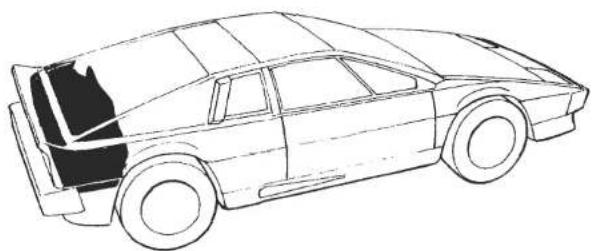
TURBO
15.24A


| ILLUSNO. | DESCRIPTION | PART NUMBER | QUANTITY | MAY 1994REMARKS | |
| PRIOR85 M.Y. | 1985M.Y.ON | ||||
| Luggage Bag Assembly | A082V5232J | 1 | |||
| Fixing Strip, Bag to Rear Panel | B082V5021K | 1 | |||
| Screw, Fixing Strip | A075W5046Z | 6 | |||
| Spire Nut, Fixing Strip | A075W6016Z | 6 | |||
| Rear Luggage Compartment Grey Fleck Carpet | |||||
| 5 | Side, LH | A082V5877K | 1 | ||
| 6 | Wheelarch, LH | A082V7226J | 1 | ||
| 7 | Engine Bay Rear Wall | A082V7227J | 1 | ||
| 8 | Floor | A082V7228J | 1 | ||
| 9 | Rear Transom | A082V7229J | 1 | ||
| 10 | Battery Board, Carpeted | A082V7230J | 1 | ||
| Button, 'Durable Dot', Carpet Fixing | A076W6109F | 10 | |||
| Socket, 'Durable Dot', Carpet Fixing | A076W6110F | 10 | |||
| 11 | Bracket, Battery Board Top Locating | A082V5882F | 2 | ||
| Pop Rivet, Battery Board Bracket | A075W6090F | 2 | |||
| Washer, Pop Rivet | A075W4001F | 2 | |||
| 12 | Infill Panel, LH Rear Corner | A082B4489K | 1 | 1 | |
| Rear, Bulkhead | A082V5897K | 1 | 1 | ||
| Rear, Quarter Light Trim Panel, RH | A082V5827K | 1 | 1 | ||
| Rear, Quarter Light Trim Panel, LH | A082V5826K | 1 | 1 | ||
| Turbo 15.24A | |||||
| d4p49 | |||||

TURBO
15.30A


| ILLUSNO. | DESCRIPTION | PART NUMBER | QUANTITY | MAY 1991REMARKS | |
| RHD | LHD | ||||
| 15.30A | |||||
| 1 | Carpet, Footwell Front | A082V723LJ | 2 | 2 | Specify or Supply Sample of Colour& Vehicle Identification Number(VIN) |
| 2 | Carpet, Front Floor, With Mat, RH | A082V7233J | 1 | ||
| Carpet, Front Floor, With Mat, RH | A082V7234J | 1 | |||
| 3 | Carpet, Front Floor, With Mat, LH | A082V7235J | 1 | * State if Ashtray in Sill | |
| Carpet, Front Floor, With Mat, LH | A082V7236J | 1 | |||
| 4 | Carpet, Underseat | A082V7239J | 2 | 2 | For Door Mounted Ashtrays, See 15.13A |
| 5 | Carpet, Front Wheelarch, With Mat, RH | A082V7240J | 1 | 1 | |
| 6 | Carpet, Front Wheelarch, With Mat, LH | A082V7241J | 1 | 1 | |
| 7 | Carpet, Sill, RH, (Inc. H/Brake Gaiter) | A082V7244J * | 1 | ) Includes GRP | |
| Carpet, Sill, RH | A082V7242J * | 1 | With Heater Only) Sill Panel | ||
| 8 | Carpet, Sill, RH | A082V7245J * | 1 | With a/c ) and (if applicable) | |
| 9 | Carpet, Sill, LH | A082V7243J * | 1 | With Heater Only) a/c hose ABS | |
| 10 | Carpet, Sill, LH | A082V7246J * | 1 | With a/c ) cover | |
| Carpet, Sill, LH, (Inc. H/Brake Gaiter) | A082V7247J * | 1 | |||
| 11 | Gaiter | A082V7261J | 1 | 1 | |
| 12 | Carpet, Tunnel Side, RH | A082V7250J | 1 | 1 | |
| 13 | Carpet, Tunnel Side, LH | A082V7251J | 1 | 1 | |
| 14 | Carpet, Rear Bulkhead, RH | A082V7252J | 1 | 1 | |
| 15 | Carpet, Rear Bulkhead, LH | A082V7253J | 1 | 1 | |
| Ashtray, Sill Mounted | A079U6062F | 2 | 2 | ||

TURBO
16.01A


| ILLUSNO. | DESCRIPTION | PART NUMBER | QUANTITY | MAY 1991REMARKS | |
| ALL | |||||
| 16.01A | |||||
| 1 | Foam, Front Floor, RH | A085V5674K | 1 | ||
| 2 | Foam, Tunnel Side, RH | A085V5672K | 1 | ||
| 3 | Foam, Tunnel Top | A085V5671K | 1 | ||
| 4 | Foam, Tunnel Side, LH | A085V5673K | 1 | ||
| 5 | Foam, Front Floor, LH | A085V5675K | 1 | ||
| 6 | Foam, Underseat | B079V4138F | 2 | ||
| 7 | Foam, Rear Bulkhead Lower, RH | A085V5719K | 1 | ||
| 8 | Foam, Rear Bulkhead Upper | A085V5670K | 1 | ||
| 9 | Foam, Rear Bulkhead Lower, LH | A085V5720K | 1 | ||
| 10 | Felt, Wheelarch, LH | B079V4095F | 1 | ||
| 11 | Felt, Wheelarch, RH | B079V4096F | 1 | ||
TURBO 16.02A
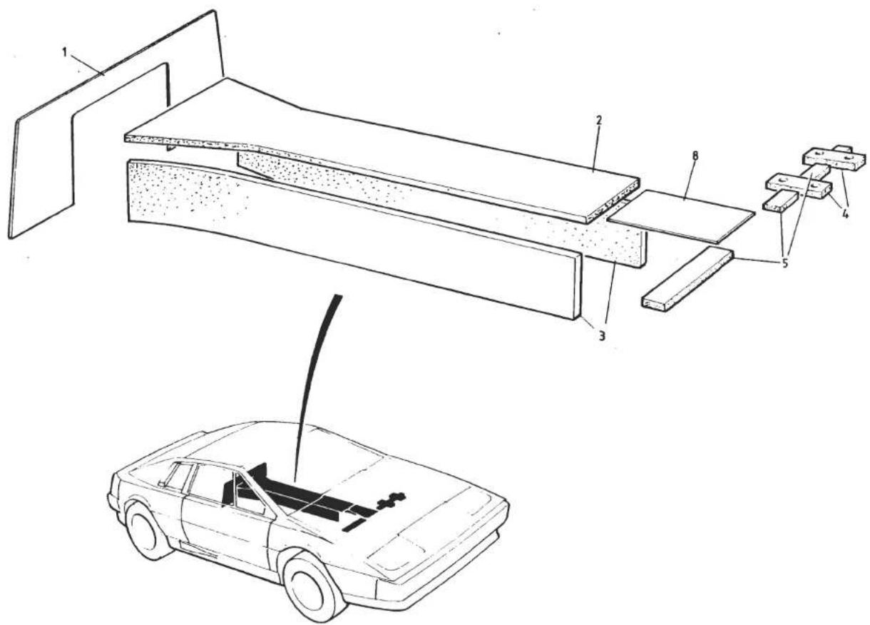


| ILLUSNO. | DESCRIPTION | PART NUMBER | QUANTITY | REMARKS | |
| ALL | |||||
| 16.02A | |||||
| 1 | Sound Barrier Mat, Rear Bulkhead | B079V4143K | 1 | '87 M.Y. on | |
| Screw, s/t, No. 6 x 1", Mat Fixing | A075W5020F | 14 | |||
| Cup Washer, Mat Fixing Screw | A075W6025F | 14 | |||
| 2 | Foam, Tunnel Top Underside | A085V5724K | 1 | ||
| 3 | Foam, Tunnel Side, Underside | A085V5725K | 2 | ||
| 4 | Foam, Pedal Box Seal | A085V5726K | 2 | ||
| 5 | Foam, Chassis Front Crossmember | A085V5727K | 1 | ||
| 8 | Pad, Anti-Squeak | A082V5759K | 1 | ||
| Sound Proofing, Engine Bay Sidewall | B082V5728K | 1 | |||
| d4p52 | Turbo 16.02A | ||||
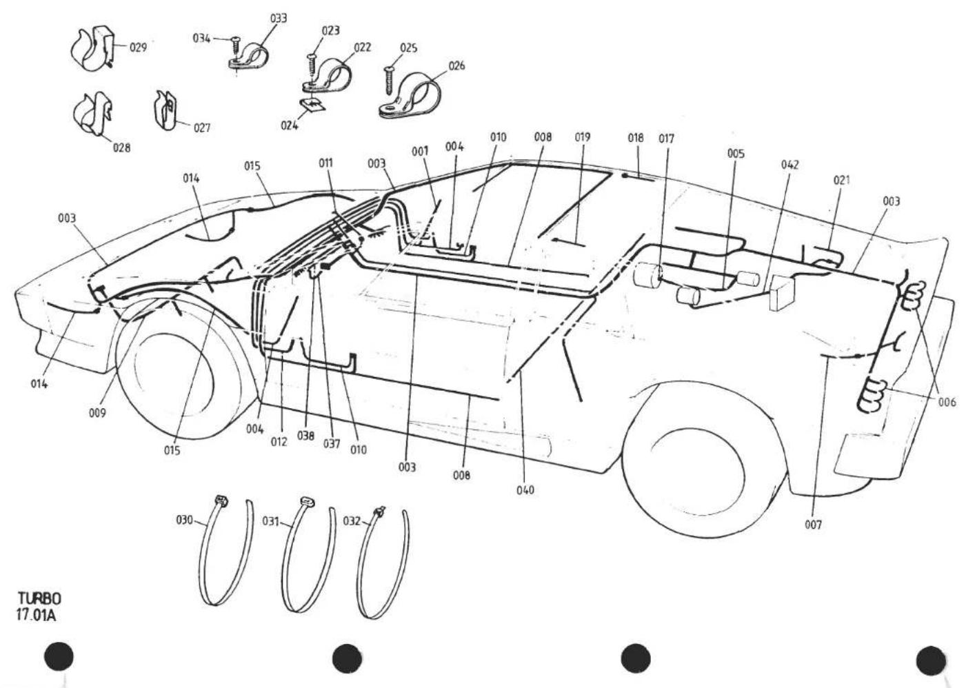
| ILLUS NO. | DESCRIPTION |  PART NUMBER PART NUMBER | QUANTITY | MAY 1991REMARKS | |
| ALL | |||||
| 001 | Extension Harness, Mirror | A082M4578F | 1 | ||
| 003 | Main Harness | B082M4117F | 1 | Prior to '87 M.Y.) | |
| Main Harness | C082M4117F | 1 | |||
| Grommet, Main Harness, Bulkhead & Engine Bay | A089M6115F | 2 | )'87 M.Y. on. H.C. Engines only) | ||
| Bush, Grommet | A089M6116F | 2 | |||
| 004 | Door Mirror Harness | A079M4095F | 1 | ||
| Harness, Door Mirror Control | A082M4615F | 1 | From VIN 82 D 213782 - 0606 | ||
| 005 | Alternator Harness | A079M4060F | 1 | ||
| 006 | Earth Lead, Tailamps | A079M4061F | 2 | ||
| 007 | Reverse Lamp Lead | A079M4062F | 1 | ||
| 008 | Door Ajar Lamp Harness | A085M4205F | 2 | ||
| 009 | Rad. Fan Harness | A082M4191F | 1 | Used Only with Rad. Fan Thermal Trip | |
| 010 | Cigar Lighter Earth Lead | A085M4206F | 2 | ||
| Cigar Lighter Harness | A079M4085F | 1 | |||
| 011 | Air Conditioning Harness | A082M4110F | 1 | With Orange 'Cartier' D.P. Fan Relay | |
| Air Conditioning Harness | C082M4110F | 1 | With Double Contact Relay | ||
| Heater Only Harness | A082M4165F | 1 | With Orange 'Cartier' D.P. Fan Relay | ||
| Heater Only Harness | C082M4110F | 1 | With Double Contact Relay | ||
| 012 | Door Harness | B079M4004F | 2 | ||
| 014 | Front Side/Turn Lamp Extension Harness | A082M6208F | 2 | For Circular Diffusion Pattern Lamps | |
| 016 | Repeater Lamp Extension Harness | A082M4188F | 2 | Used Only With Later Type Repeater Lamps | |
| 017 | Boot, Starter/Alternator Terminals | A075M6174F | 2 | ||
| 018 | Lead, Heated Rear Screen | A082M4136F | 1 | ||
| 019 | Lead, Heated Rear Screen | A082M4137F | 1 | ||
| 021 | Ignition Harness | A082M4126Z | 1 | With 'Lumenition' Ignition | |
| Ignition Harness | A082M4198F | 1 | With Lucas 'Constant Energy' Ignition | ||
| 022 | 'P' Clip, Ignition Harness to Ign. Box | A075W6000Z | 1 | ||
| 023 | Screw, 'P' Clip Fix | A075W5015Z | 1 | ||
| 024 | Spire Nut, 'P' Clip Fix | A079W6024Z | 1 | ||
| 025 | Screw, No. 6 x 3/4", Loom Fix | A075W5028Z | 6 | ||
| 026 | 'P' Clip, Loom Fix | A075W6021Z | 2 | ||
| 'P' Clip, Door Mirror Control Harness | A075W6228F | 4 | ) From VIN 82 D 2137) 82 - 0606Turbo 17.01APage 1 | ||
| Pop Rivet, Clip Fix | A082W6243F | 4 | |||
| d4p53 | |||||

| ILLUS NO. | DESCRIPTION |  PART NUMBER PART NUMBER | QUANTITY | MAY 1991 REMARKS | |
| ALL | |||||
| 17.01A | |||||
| 027 | Clip, Loom Fix | A075W6018Z | 2 | ||
| 028 | Clip, Loom Fix | A079W6115F | 2 | ||
| 029 | Clip, Loom Fix | A085W6258F | 5 | ||
| 030 | Cable Tie, 312 mm | A075W6038Z | 25 | ||
| 031 | Cable Tie, 220 mm | A075W6045Z | 13 | ||
| 027 | Clip, Loom Fixing | A075W6018Z | 2 | ||
| 028 | Clip, Loom Fixing | A079W6115F | 2 | ||
| 029 | Clip, Loom Fixing | A085W6258F | 5 | ||
| 030 | Cable Tie, 312 mm | A075W6038Z | 25 | ||
| 031 | Cable Tie, 220 mm | A075W6045Z | 13 | ||
| 032 | Cable Tie, 455 mm | A079W6224F | 5 | ||
| 033 | 'P' Clip, Small | A075W6223F | 10 | ||
| 034 | Screw, No. 6 x 1/4", 'P' Clip Fix | A075W5010Z | 10 | ||
| 037 | Harness, Radio Feed | A082M4577F | 1 | Motorola, Sparkomatic, Blaupunkt | |
| 038 | Harness, Aerial Switch | A082M4579F | 1 | ||
| Speaker Loom, Front | A082M4588F | 1 | For Blaupunkt 'Quickfit' Fascia Speakers | ||
| 040 | Speaker Loom, Rear | A082M4589K | 1 | Routed Along Tunnel | |
| 042 | Lead, Ignition Amplifier to Distributor | A089M6037F | 1 | With Lucas Constant Energy Ignition | |
| Grommet, Ignition Box | A082M6286H | 1 | |||
| Harness, Engine Management | A085M4626F | 1 | '87 M.Y. on | ||
| Diode, 1 AMP (Black) | B075M6141Z | A/R | |||
| Turbo 17.01A | |||||
| Page 2 | |||||
| d4p54 | |||||

| ILLUS NO. | DESCRIPTION |  PART NUMBER PART NUMBER | QUANTITY | REMARKS | |
| PRIOR '87 M.Y | '87 M.Y ON | ||||
| 17.03A | |||||
| 1 | Flasher Unit, Hazard | A007M4124Z | 1 | 1 | |
| 2 | Clip, Hazard Flasher Unit | X036M6301F | 1 | 1 | |
| 3 | Flasher Unit, Turn Indicators | A079M6018F | 1 | 1 | |
| Screw, Flasher Unit Fixing | A075W5012F | 1 | 1 | ||
| Spire Nut, Flasher Unit Fixing | A075W6013Z | 1 | 1 | ||
| 4 | Relay, Double Contact | A082M6182F | 2/3/4 | 4 | Inner H/L (2), Rad. Fans (1) (For Cars Fitted With Thermal Trip), Interior Fans (1) (For Cars NOT Fitted With Orange 'Cartier' Relay). |
| 5 | Relay, Changeover, Silver 30 Amp | A079M6141F | R/B B079M6141F | ||
| Relay, Changeover, Black 40 Amp | B079M6141F | 5/6/7/8 | Horn (1), H/L Control (1) (Prior to Fitment of Diode), H/L Flasher (1), H/L Motor RH (1), H/L Motor LH (1), Fan Fail (1) (Prior to Thermal Trip), HRS (1). | ||
| 6 | Relay, Changeover, Black 40 Amp | B079M6141F | 5/6 | '87 M.Y. On. Throttle Jack, Purge Pump Ignition Solenoid Valve, Overboost Switch Dim-Dip. A/C Compressor (With Switch A082M6221F) | |
| 7 | Fused Relay, 4RA, Radiator Fans | A079M6101F | 1 | Prior to Thermal Trip | |
| 'Cartier' Relay, Interior Fans (Orange) | A083M6218F | 1 | Prior to Relay A082M6182F | ||
| Moulding 'Cartier' Relay | A083M6229F | 1 | |||
| Diode, Headlamp Changeover Circuit | B075M6141Z | 1 | 1 | Later Cars Not Using Relay B079M6141F | |
| 8 | Relay Bridge, Rad. Fan Circuit | A082M4195F | 1 | 1 | With Fan Thermal Trip |
| 9 | Delay Unit, Wipers | A079M6126F | 1 | 1 | |
| 10 | Spacer, Delay Unit to Fascia | A907E0696Z | 2 | 2 | |
| Delay Unit, Interior Lamp, Progressive Dimmer | A082M6143F | 1 | >As Fitted | ||
| 11 | Delay Unit, Interior Lamp, Timed Switch | A082M6220F | 1 | 1 | > |
| 14 | Horn, Low Note | A079M6086F | 1 | ) | |
| 15 | Horn, High Note | A079M6087F | 1 | ) Electric Horns | |
| 16 | Bracket, Horn Mounting | A079M6089F | 2 | ) | |
| 17 | Air Horn Kit | A089M6063F | 1 | 1 | With Air Horns |
| d4p58 | Turbo 17.03APage 1 | ||||
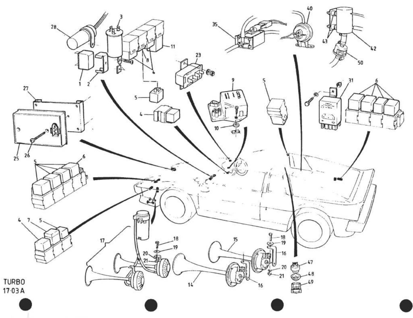
| ILLUS NO. | DESCRIPTION |  PART NUMBER PART NUMBER | QUANTITY | MAY 1991REMARKS | |
| PRIOR'87 M.Y | '87 M.YON | ||||
| 17.03A | |||||
| 18 | Setscrew, M6 x 25, Horn Brkt. to Body | A075W1031Z | 2 | 2 | |
| 19 | Washer, Flat, Brkt. Fixing | A075W4015Z | 2 | 2 | |
| 20 | Washer, 25mm O/D, Brkt Fixing | A075W4017Z | 2 | 2 | |
| 21 | Nut, Nyloc, M6, Brkt. Fixing | A075W3009Z | 2 | 2 | |
| 23 | Voltage Stabiliser | A079N6027F | 1 | 1 | |
| Diode, Brake Warning Lamp | B075M6141Z | 1 | 1 | ||
| 25 | Module, 'Dim-Dip' | A085M6315F | 1 | ) | |
| 26 | Screw, M4 x 30, Unit Fix | A085W5112F | 2 | )U.K. only | |
| 27 | Bracket, Relay Mounting | A085U5112F | 1 | ) | |
| Pop Rivet, Brkt. Fix | A075W6071F | 4 | ) | ||
| 28 | Module, Low Coolant | A082M6275F | 1 | ||
| Screw, s/t, Module Fix | A075W5012F | 2 | |||
| Spire Nut, Module Fix | A075W6013F | 2 | |||
| 'P' Clip, Module Fix | A075W6229F | 1 | |||
| 31 | Relay Engine Speed Sensing | A910E6757F | 1 | Throttle Jack Control | |
| Screw, Relay Fix | A075W1002Z | 1 | |||
| Nut, Nyloc, 10 UNF, Relay Fix | A075W3000Z | 1 | |||
| Washer, Relay Fix | A075W4011Z | 1 | |||
| 35 | Ignition Solenoid Valve | A910E6764F | 1 | ||
| Screw, s/t, No. 8 x 3/8", Solenoid Fix | A075W5032Z | 2 | |||
| Washer, Solenoid Fix | A075W4011Z | 2 | |||
| 40 | Overboost Switch | A082M4610K | 1 | ||
| Screw, No. 8 x 1⁄2", Switch Fix | A075W5034Z | 2 | |||
| 42 | Purge Pump | A089M6105F | 1 | ||
| 43 | Resilient Mounts, Purge Pump | A089M8042K | 2 | ||
| Nut, M6, Purge Pump Fix | A075W3020F | 2 | |||
| Washer, Internal Spring, Purge Pump Fix | A075W4046F | 2 | |||
| 47 | Thermal Switch, Purge Pump Control | A082M6317F | 1 | MOR 70, BOF 60. Includes Grommet | |
| 48 | Grommet, Purge Pump Switch | A079M6181F | 1 | ||
| 49 | Clip, Switch Retention | A079M6138F | 1 | ||
| 50 | Solenoid Valve, Purge Line Shut-Off | A082L4130F | 1 | ||
| d4p79 | Turbo 17.03APage 2 | ||||

| ILLUS NO. | DESCRIPTION |  PART NUMBER PART NUMBER | QUANTITY | REMARKS | |
| ALL | |||||
| 17.05A | |||||
| 001 | Light Source, Fibre Optics | B079M6099F | 1 | ||
| 002 | Bulb, 12V 5W, Light Source | A075M6144F | 1 | ||
| 003 | Clip, Fibre Optic Carrier to Switch | A079M6100F | 4 | ||
| 004 | Fibre Optic Light Carrier, 880mm | B079M6097F | 1 | ||
| 005 | Fibre Optic Light Carrier, 435mm | B079M6098F | 2 | ||
| 006 | Rheostat, 27W, Binnacle/Switch Illum. | A083M6220F | 1 | Identification Number 78546 | |
| 007 | Rheostat, 19.8W, Heater/Cigar Illum. | A079M6029F | 1 | Identification Number 78526 | |
| 008 | Knob, Rheostat, Plain | A082M6153F | 2 | R/B A089M0490F | |
| Knob, Rheostat, with Graphic | A089M0490F | 2 | |||
| Heatshield, Rheostat | A083M0376K | 2 | If Fitted | ||
| 009 | Blanking Plug, Light Source | A082M6240F | 4 | ||
| 011 | Cigar Lighter, Inner & Outer | A079M6123J | 2 | ||
| 012 | Illumination Ring, Cigar Lighter | A079M6124F | 2 | ||
| 013 | Bracket, Cigar Lighter Mounting | A079M4088K | 2 | ||
| Pop Rivet, Brkt. Fixing | A075M6092Z | 8 | |||
| Switch, Dip/Flash/Turn/Horn | A075M6072Z | 1 | On RH Side of Steering Column | ||
| 015 | Switch, Dip/Flash/Turn/Horn | A082M6151Z | 1 | On LH Side of Steering Column | |
| Switch, Wash/Wipe | B075M6073Z | 1 | On LH Side of Steering Column | ||
| 016 | Switch, Wash/Wipe | A082M6152Z | 1 | On RH Side of Steering Column | |
| 017 | Bracket, Switches to Column | B075M6051Z | 1 | ||
| 018 | Screw, 10 UNC x 119, | A075M6074Z | 2 | Wash/Wipe Switch to Bracket | |
| 019 | Screw, 10 UNC x 135 | A075M6075Z | 2 | Dip/Flash/Turn Switch to Bracket | |
| 020 | Spacer, Switches to Column | B079M4017F | 1 | ||
| 021 | Switch, Lighting | B079M6134F | 1 | ||
| 022 | Clip, Bulbholder | A079M6135F | 1 | ||
| 023 | Switch, Hazard Warning Lamps | B079M6063F | 1 | ||
| 024 | Switch, Rear Fog Lamps | A075M6206F | 1 | ||
| 028 | Switch, Heated Rear Screen | A075M6212F | 1 | ||
| 029 | Switch, Window Lift | B079M6068F | 2 | ||
| 030 | Clip, Window Switch Retention | A079U4657F | 2 | ||
| Turbo 17.05APage 1 | |||||
| d4p10 | |||||

| ILLUS NO. | DESCRIPTION |  PART NUMBER PART NUMBER | QUANTITY | MAY 1991REMARKS | |
| ALL | |||||
| 031 | Switch, Mirror Adjust | A079M6111F | 1 | Prior to Change Point * | |
| Switch, Mirror Adjust | A082M6300F | 1 | ) | ||
| Nut, 3/4 UNF, Switch Retaining | A082M6304F | 1 | ) | ||
| Spacer, Mirror Adjust Switch | A082U5067F | 1 | )From Change Point * | ||
| Bezel, Mirror Adjust Switch | A082U5068F | 1 | ) | ||
| Spring Clip, Bezel Retaining | A082M6303F | 1 | ) | ||
| 032 | Switch, Mirror Select | A075M0339F | 1 | Prior to Change Point * | |
| Switch, Mirror Select | A082M6301F | 1 | From Change Point * | ||
| 033 | Switch, Interior Fan Speed | A082M6145F | 1 | R/B A082M6223F | |
| Switch, Interior Fan Speed | A082M6223F | 1 | |||
| 034 | Switch, Radio Aerial | A075M0339F | 1 | ||
| 035 | Knob, Fan Speed Switch | A082P4186F | 1 | R/B Knob A089P6102F & Cap A089P6103F | |
| Knob, Fan Speed Switch | A089P6102F | 1 | |||
| Cap, Fan Speed Switch Knob | A089P6103F | 1 | |||
| Control Switch Assy. Fridge Temp | A079P6013F | 1 | Prior to VIN 82 D 215382 - 0602 | ||
| 039 | Control Switch, Fridge Temp | A082M6221F | 1 | ) | |
| 040 | Cover, Control Switch, (ABS) | A082M4239K | 1 | ) From VIN 82 D 2153 | |
| 041 | Control Unit, Fridge Temp | A082M4605F | 1 | ) 82 - 0602 | |
| Harness, Control Unit to Relay | A082M4585F | 1 | |||
| Knob, Fridge Switch | A082P4186F | 1 | R/B Knob A089P6102F & Cap A089P6103F | ||
| Knob, Fridge Switch | A089P6102F | 1 | |||
| Cap, Fridge Switch Knob | A089P6103F | 1 | * Change Point VIN 82 D 213782 - 0606 | ||
| Turbo 17.05APage 2 | |||||
| d4p59 | |||||

| ILLUS NO. | DESCRIPTION |  PART NUMBER PART NUMBER | QUANTITY | MAY 1991REMARKS | |
| PRIOR '87 M.Y | '87 M.Y ON | ||||
| 17.07A | |||||
| 001 | Clock, Digital,LED (Rocking Bar Adjustment) | A079M6088F | 1 | Early Cars, Flat Connector Block | |
| Clock, Digital,LED (Pin Button Adjustment) | A089M6034F | 1 | |||
| Clock, Digital,LED (Rocking Bar Adjustment) | A082M4619F | 1 | 1986 M.Y. Round Connector Block. (R/B A082M6341F & Jump Harness A082M4689F) | ||
| Clock, Digital,LCD | A082M6341F | 1 | |||
| 002 | Screw, M4 x 20, Clock Fixing | A079W5083F | 2 | ) | |
| 003 | Washer, Flat, Clock Fixing | A075W4062F | 2 | )Use with Clock A089M6034F | |
| 004 | Nut, Nyloc, M4, Clock Fixing | A075W3049F | 2 | ) | |
| 005 | Speedometer, 170 mph, RHD | A079N6032F | 1 | White Illumination | |
| Speedometer, 170 mph, RHD | A082N6040F | 1 | 1 | Green Illumination | |
| Speedometer, 265 kph, LHD | A079N6033F | 1 | White Illumination | ||
| Speedometer, 260 kph, LHD | A082N6041F | 1 | 1 | Green Illumination | |
| Bulb, Speedo Illumination | A089M6047F | 1 | 1 | For Speedo A082N6040/1F | |
| 006 | Fuel Gauge | A079N6024F | 1 | White Illumination | |
| Fuel Gauge | A082N6044F | 1 | 1 | Green Illumination | |
| 007 | Boost Gauge | A082N6035F | 1 | R/B A082N6047F | |
| Boost Gauge | A082N6047F | 1 | 1 | ||
| 008 | Bracket, Boost Gauge Illumination | A082N4007J | 1 | 1 | |
| Lens, Green, Illumination Bracket | A082N6049F | 1 | 1 | ||
| Check Screw, Gauge Damping | A082N6039F | 1 | |||
| 012 | Water Temperature Gauge | A079N6023F | 1 | White Illumination | |
| Water Temperature Gauge | A082N6043F | 1 | 1 | Green Illumination | |
| 013 | Oil Pressure Gauge | A079N6026F | 1 | White Illumination | |
| Oil Pressure Gauge | A082N6046F | 1 | 1 | Green Illumination | |
| 014 | Tachometer | A079N6022F | 1 | White Illumination | |
| Tachometer | A082N6042F | 1 | 1 | Green Illumination | |
| Bulb, Tacho Illumination | A089M6047F | 1 | 1 | For Tacho A082N6042F | |
| 015 | Voltmeter, Battery Condition Gauge | A079N6025F | 1 | White Illumination | |
| Voltmeter, Battery Condition Gauge | A082N6045F | 1 | 1 | Green Illumination | |
| 016 | Tell-Tale Light Assembly, RH | A082N4004F | 1 | With Separate Low Fluid & Park. Brake Lamp | |
| Tell-Tale Light Assembly, RH | B082N4004F | 1 | 1 | With Combined Low Fluid & Park. Brake Lamp | |
| 017 | Tell-Tale Light Assembly, LH | A082N4005F | 1 | With Separate Fuel & Choke Lights | |
| Tell-Tale Light Assembly, LH | A082N4008F | 1 | With Combined Fuel/Choke Light | ||
| 019 | Tell-Tale Light Assembly, Centre | A082M6278F | 1 | ||
| 020 | Lens, Low Oil Pressure Tell-Tale | A082M6279F | 1 | ||
| 021 | Lens, Low Coolant Level Tell-Tale | A082M6280F | 1 | ||
| d4p55 | Turbo 17.07A | ||||

TURBO
17.09A


| ILLUSNO. | DESCRIPTION | PART NUMBER | QUANTITY | MAY 1891REMARKS | |
| ALL | |||||
| 17.09A | |||||
| 1 | Speedo Cable | A079N6034F | 1 | R/B Items 5,6,7 and Take-Off Elbow A910E6772 (See 42.01A) | |
| 2 | 'P' Clip, Cable to Chassis | A075Q6016F | 1 | ||
| 3 | Pipe, Oil Pressure Gauge, Nut Fitting | A079N4001F | 1 | ||
| 4 | Pipe, Boost Gauge, Nut Fitting | A079N4001F | 1 | ||
| 5 | Pipe, Boost Gauge, Plain End | A082N4019F | 1 | ||
| 6 | Connector Tube, Boost Pipe to Engine | A082N4020K | 1 | ||
| 7 | Restrictor, Boost Gauge Pipe | A912E6452H | 1 | ||
| 8 | Washer, Oil/Boost Pipe to Gauge | A036N6000F | 2 | ||
| d4p56 | Turbo 17.09A | ||||
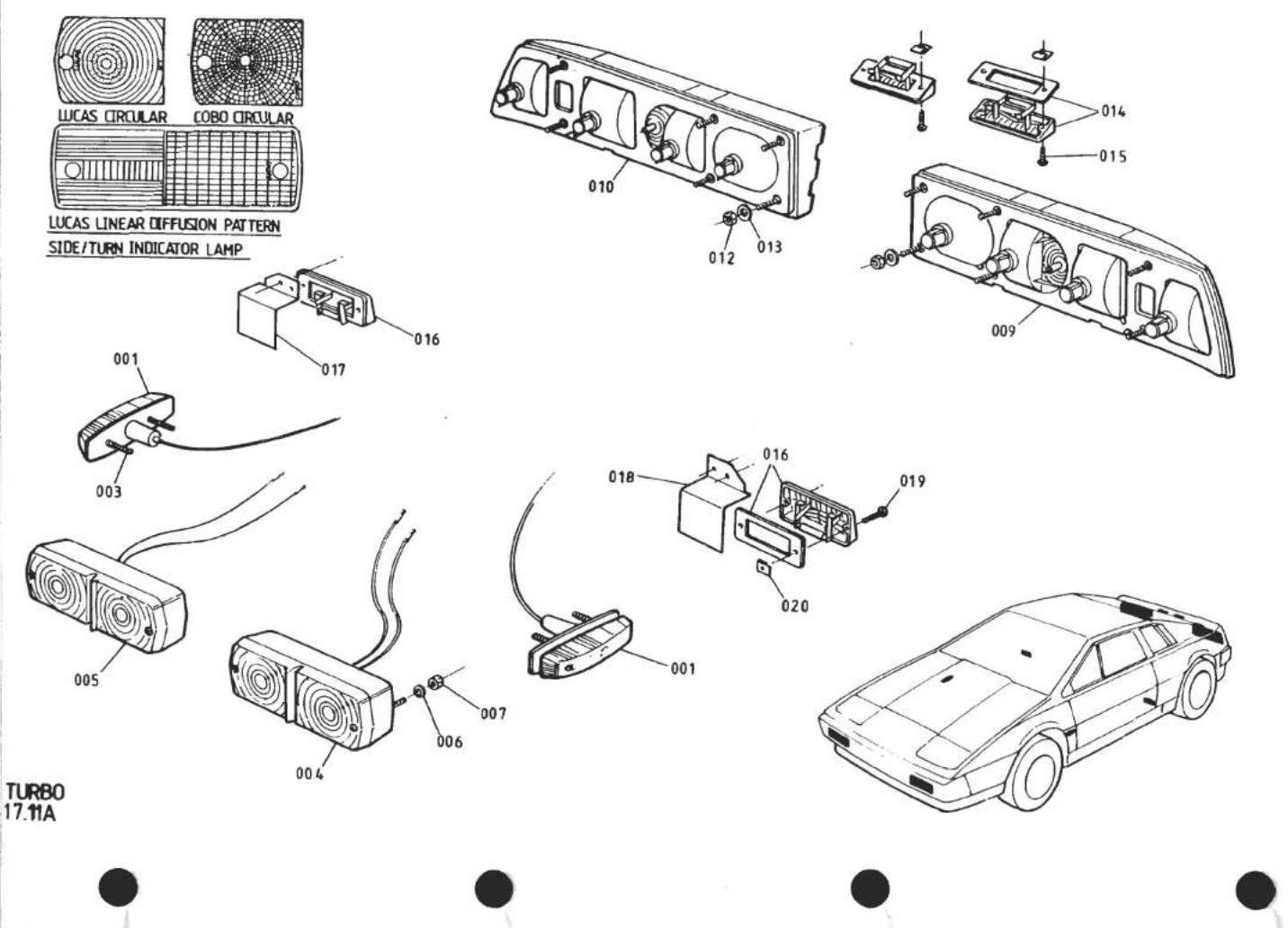
TURBO
17.11A
| ILLUS NO. | DESCRIPTION |  PART NUMBER PART NUMBER | QUANTITY | MAY 1991REMARKS | |
| ALL | |||||
| 17.11A | |||||
| 001003 | Turn Repeater Lamp | A075M6140W | 2 | R/B Lamp A082M6180F and Extension Harness A082M4188F | |
| Turn Repeater Lamp | A082M6180F | 2 | |||
| Screw, Lamp Fixing | A075W5028Z | 4 | |||
| Side/Turn Lamp, LH | A075M6029W | 1 | ] | ||
| Side/Turn Lamp, RH | A075M6028W | 1 | ]Linear Diffusion Pattern, 'Lucas' | ||
| Lens, Side/Turn Lamp | A075M6119Z | 2 | ] | ||
| Screw, Lamp Fixing | A075W5034Z | 8 | ] | ||
| Spire Nut, Lamp Fixing | A075W6171F | 8 | ] | ||
| 004005 | Side/Turn Lamp, LH | A089M6022F | 1 | } | |
| Side/Turn Lamp, RH | A089M6021F | 1 | }Circular Diffusion Pattern, 'Lucas' | ||
| Lens, Side/Turn Lamp | A089M6061F | 2 | } | ||
| 006007 | Washer, Flat, Lamp Fixing | A075W4013Z | 4 | } | |
| Nut, Nyloc, M6, Lamp Fixing | A075W3009Z | 4 | } | ||
| Side/Turn Lamp, LH | A089M6073F | 1 | > | ||
| Side/Turn Lamp, RH | A089M6074F | 1 | >Circular Diffusion Pattern, 'Cobo' | ||
| Lens, Side/Turn Lamp | A089M6083F | 2 | > | ||
| Setscrew, M6 x 25, Lamp Fix | A075W1031F | 4 | > | ||
| Washer, M6, Lamp Fix | A075W4013Z | 8 | > | ||
| Washer, Lamp Fix | A075W4017Z | 2 | > | ||
| Nut, Nyloc, M6, Lamp Fix | A075W3009Z | 4 | > | ||
| 009 | Rear Lamp Assy. LH | A079M6093F | 1 | ||
| Rear Lamp Assy. RH | A079M6094F | 1 | |||
| 012 | Nut, Lamp Fix | A075W3008Z | 12 | ||
| 013 | Washer, Lamp Fix | A075W4000Z | 12 | ||
| 014 | Licence Plate Lamp | A082M6144F | 2 | ||
| 015 | Screw, Lamp Fix | A075W5015Z | 4 | ||
| 016 | 'Door Open' Warning Lamp (inc. Gasket) | A082M6155F | 2 | ||
| 017 | Shield, Door Lamp, LH | A082U4743K | 1 | ||
| 018 | Shield, Door Lamp, RH | A082U4742K | 1 | ||
| 019 | Screw, Lamp Fix | A075W5027Z | 4 | ||
| 020 | Spire Nut, Lamp Fix | A079W6024F | 4 | ||
| d4p57 | Turbo 17.11A | ||||
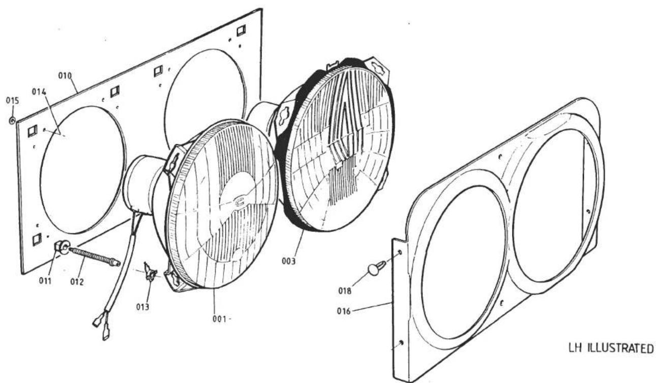
TURBO 17.13A
| ILLUSNO. | DESCRIPTION | PART NUMBER | QUANTITY | MAY 1991REMARKS | |
| RHD | LHD | ||||
| 17.13A | |||||
| 001003 | Headlamp Assembly, Lucas/HellaHeadlamp Unit, Lucas/HellaHeadlamp Assembly, Lucas/HellaHeadlamp Unit, Lucas/Hella | A079M6106KA079M6104FA079M6105KA079M6103F | 44 | Frame/Unit/BulbIncludes H4 BulbFrame/Unit/BulbIncludes H4 Bulb | |
| Headlamp Assembly, Inboard, CibieHeadlamp Assembly, Outboard, CibieHeadlamp Assembly, Outboard, CibieBulb, Halogen H4, Beam/DipBulb, Halogen HI, Beam OnlyBulb, Halogen, H4, YellowScrew, Headlamp to PodSpire Nut, Headlamp to Pod | A082M6174FA085M4223JA085M4224JA075M6126FA082M6288FA079M6113FA075W5043ZA075W6016Z | 224/221616 | 224/2241616 | Main Beam Only, HI BulbUnit/Carriage Plate/Bezel/H4 BulbUnit/Carriage Plate/Bezel/H4 BulbCibie InboardFrance Only. Lucas/Hella LampsLucas/HellaLucas/Hella | |
| 010011012013014015 | Plate, Headlamp Mounting to PodInsert Bush, Adjuster Screw to PlateAdjuster Screw, Headlamp AimCapsule, 1/4 Turn, Headlamp MountingPop Rivet, Mtg. Plate to PodWasher, Pop RivetSurround, Headlamps, LHSurround, Headlamps, RScrew, Surround to Pod | A085M4217FA082M6207FA082M6206FA085M6217FA075W6069FA075W4062FA079U4449KA079U4450KA075W5030F | 2121232321181181111112 | 212121232321181111111111111111111111111111111111111111111111111111111111111111111111111111111111111111111111111111 | > |
| 016 | Surround, Headlamps, LHSurround, Headlamps, RSSurround, Headlamps, LHSurround, Headlamps, RS | A085M4222KA085M4221KB085M4222KB085M4221KA075W6192F | 111111111111111111111111111111111111111111111111111111111111111111111111111111111111111111111111111 | ) )Lucas/Hella Headlamps) Prior to VIN 82 D 2265 >82 - 0625 >Cibie)From VIN 82 D 2265 >Headlamps) 82 - 0625 >Turbo 17.13A | |
| 018 | Button Clip, Surround to Pod | ||||
| d4p60 | |||||
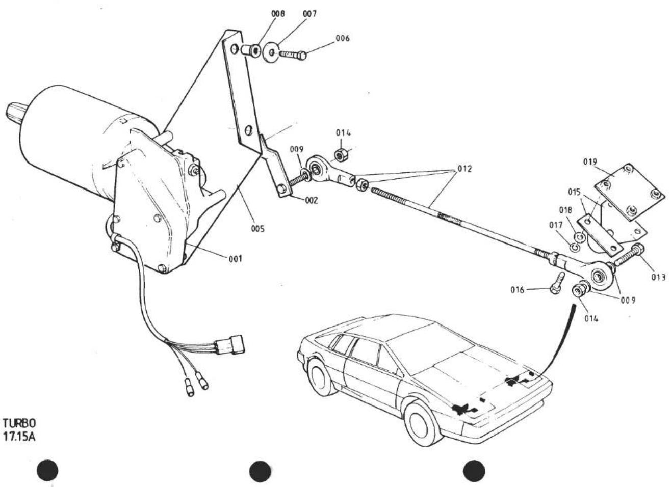
| ILLUSNO. | DESCRIPTION |  PART NUMBER PART NUMBER | QUANTITY | MAY 1991REMARKS | |
| ALL | |||||
| 17.15A | |||||
| 001 | Motor Assembly, Headlamp Pod | B079M6047F | 2 | R/B A082M4584F | |
| Motor Assembly, Headlamp Pod | A082M4584F | 2 | Inc. Rotary Link | ||
| 002 | Rotary Link | D079M4055K | 2 | ||
| 005 | Bracket, Headlamp Motor Mounting | A079U4453K | 2 | ||
| 006 | Setscrew, 1/4" UNF x 3/4" Brkt/Body | A075W1005Z | 8 | ||
| 007 | Washer, Bracket/Body | A075W4015Z | 8 | ||
| 008 | Rawlnut, 1/4" UNF, Bracket/Body | A075W6036Z | 8 | ||
| 009 | Washer, Flat, Rod End | A075W4013Z | 8 | ||
| Connecting Link, Pod Actuation | A079U4455F | 2 | ) | ||
| Rod End, 1/4" UNF, Connecting Link | A079U6031F | 4 | )R/B Assembly A082U5006F | ||
| Locknut, 1/4" UNF, Rod End | A075W3038Z | 4 | ) | ||
| 012 | Linkage Assembly, Pod Actuation | A082U5006F | 2 | M6 RH/LH Threads | |
| 013 | Setscrew, M6 x 30, Link to Pod | A075W1032Z | 2 | ||
| 014 | Nut, Nyloc, M6, Link Fixing | A907E6285F | 4 | ||
| 015 | Bracket, Link to Pod | A079U4454K | 4 | ||
| 016 | Setscrew, M6 x 18, Bracket to Pod | A075W1029F | 8 | ||
| 017 | Washer, Shakeproof, Bracket to Pod | A075W4046Z | 8 | ||
| 018 | Washer, Flat, Bracket to Pod | A075W4015Z | 8 | ||
| 019 | Tapping Plate, Bracket to Pod | A079U4517F | 2 | ||

TURBO
17.17A


| ILLUSNO. | DESCRIPTION |  PART NUMBER PART NUMBER | QUANTITY | MAY 1991REMARKS | |
| ALL | |||||
| 1 | Interior Lamp (with rocking lens switch) | A082M6156F | 1 | From 1986 | |
| 2 | Bracket, Interior Lamp Mounting | A082U4726K | 1 | ||
| 3 | Bulb, Festoon, Interior Lamp, 6W | A083M6292F | 1 | ||
| 5 | Interior Lamp (with button switch) | A083M6291F | 1 | ||
| 6 | Bracket, Interior Lamp Mounting | B079V4454K | 1 | ||
| 7 | Bulb, Festoon, Interior Lamp, 10W | A082M6310F | 1 | ||
| 9 | Door Switch, Courtesy Lamp | A075M6044Z | 2 | ||
| 10 | Spacer Washer, Fibre, Switch Adjust | A075W4057Z | A/R | ||
| d4p62 | Turbo 17.17A | ||||

| ILLUS NO. | DESCRIPTION |  PART NUMBER
 | QUANTITY | 1651 A/W REMARKS | |
| ALL | |||||
| 001 | Thermal Trip, 3-Way, Rad. Fans | A082M6196F | 1 | Red Spot. R/B B082M6196F Green Spot | |
| Thermal Trip, 3-Way, Rad. Fans | B082M6196F | 1 | |||
| 002 | Mounting Bracket, Thermal Trip | A082M4196F | 1 | ||
| Pop Rivet, Trip Connector Mldg/Brkt. | A075W6096F | 1 | |||
| 004 | Screw, Mounting Bracket to Body | A075W5012F | 2 | ||
| 005 | Inertia Switch, Fuel Pump Cut Out | B079M6133F | 1 | ||
| Bolt, M5 x 50, Switch Fix | A079W2026F | 2 | |||
| Nut, Full, M5, Switch Fix | A082W3084F | 2 | |||
| Washer, Shakeproof, Switch Fix | A075W4045Z | 2 | |||
| 006 | Fusebox | A079M6037F | 2 | ||
| Screw, 2BA x 1", Fusebox Fixing | A075W5054Z | 4 | |||
| Nut, Nyloc, 2BA, Fusebox Fixing | A075W3001Z | 4 | |||
| Turbo 17.19A | |||||
| d4p63 | |||||

| ILLUS NO. | DESCRIPTION |  PART NUMBER PART NUMBER | QUANTITY | MAY 13 | |
| RHD | LHD | REMARKS | |||
| 17.21A | |||||
| 001 | Wiper Motor, 16W | B075M6021F | 1 | 1 | R/B A085M6163F |
| Wiper Motor, 29W, Inc. Clamp & Pad | A085M6163F | 1 | 1 | Bronze Coloured Motor Casing | |
| Clamp & Pad, Motor Mounting | A079M4022F | 1 | 1 | ||
| 002 | Setscrew, M6 x 30, Clamp to Body | A075W2028Z | 2 | 2 | |
| 003 | Washer, 25mm O/D, Motor Mtg. | A075W4017Z | 2 | 2 | |
| 004 | Nut, Nyloc, M6, Motor Mtg. | A075W3009Z | 2 | 2 | |
| 005 | Bundy Tube, Motor to Wheelbox | A079M4140F | 1 | 1 | |
| 006 | Bundy Tube, Wheelbox Run-out | X026M0012J | 1 | 1 | |
| Wheelbox Assembly, Inc. Nuts | A076M0309F | 1 | 1 | For 'Push-On' Type Wiper Arm R/B B083M6227F With Associated Parts | |
| Bracket, Wheelbox Stabilising | A079M4021K | 2 | 2 | ) | |
| Setscrew, Bracket to Body | A075W1003F | 2 | 2 | ) | |
| Washer, Bracket to Body | A075W4000Z | 2 | 2 | ) | |
| Nut, Torqloc, Bracket to Body | A075W3000Z | 2 | 2 | ) | |
| Spacer, Wheelbox to Body | A079M4077F | 1 | 1 | )'Push-on' Wiper Arm | |
| Spacer, Locking Plate to Body | A079M4077F | 1 | 1 | ) | |
| Locking Plate, Pantograph Arm | A079M4015K | 1 | ) | ||
| Locking Plate, Pantograph Arm | A079M4016K | 1 | ) | ||
| Screw, Locking Plate to Body | A075W5040Z | 1 | 1 | ) | |
| 007 | Wheelbox Assembly Inc. Nuts | B083M6227F | 1 | 1 | |
| 008 | Bracket, Wheelbox Stabilising | A085U4788K | 2 | 2 | |
| 010 | Setscrew, Bracket to Body | A075W1003F | 2 | 2 | |
| 011 | Washer, Bracket to Body | A075W4000Z | 2 | 2 | |
| 012 | Nut, Torqloc, Bracket to Body | A075W3000Z | 2 | 2 | |
| 013 | Spacer, Wheelbox to Body, 13mm | B085U4789F | 1 | 1 | )Selected by > |
| Spacer, Wheelbox to Body, 9mm | A079M4077F | 1 | 1 | )Body Thickness > | |
| 014 | Spacer, Locking Plate to Body, 9mm | A079M4077F | 1 | 1 | With p/g swivel joint > |
| Spacer, Locking Plate to Body, 6.5mm | A082M4256K | 1 | 1 | with p/g ball joint > | |
| d4p64 | |||||

| ILLUSNO. | DESCRIPTION |  PART NUMBER PART NUMBER | QUANTITY | MAY 1991REMARKS | |
| ALL | |||||
| 17.27A | Radio/Cassette Unit | A082M6166F | 1 | National Panasonic 973 | |
| Radio/Cassette Unit | A084M6035F | 1 | National Panasonic 583 | ||
| Radio/Cassette Unit | A089M6027F | 1 | Motorola 'Lotus' | ||
| Radio/Cassette Unit | A089M6051F | 1 | Sparkomatic SR309F | ||
| Radio/Cassette Unit | A089M6328F | 1 | Blaupunkt Cambridge | ||
| Radio/Cassette Unit | A089M6329F | 1 | Blaupunkt Boston | ||
| Radio/Cassette Unit | A082M6266F | 1 | Blaupunkt Toronto | ||
| Radio/Cassette Unit | A089M6082F | 1 | Clarion '950' | ||
| Radio/Cassette Unit | A089M6119F | 1 | Clarion '920' | ||
| Fitting Kit, Blaupunkt Units | A082M6267F | 1 | R/B A082M6309F | ||
| Fitting Kit, Blaupunkt Units | A082M6309F | 1 | |||
| Diode, 1 Amp, Radio Harness | B075M6141F | 2 | )National Panasonic Unit | ||
| Support Bracket, Radio to Tunnel | A079P4083K | 1 | ) | ||
| Speaker, 4 ohm, Front/Rear | A082M6167F | 2/4 | Audax. No Grilles on Fascia | ||
| Grille, Speaker, Rear Bulkhead | A082M6160F | 2 | With Audax Speakers | ||
| Spacer, Speaker | A082M4115F | 2/4 | " " " | ||
| Screw, M4 x 20, Front Speaker Fix | A079W5083F | 6 | " " " | ||
| Nut, M4, Front Speaker Fix | A075W3019F | 6 | " " " | ||
| Washer, Front Speaker Fix | A075W4011F | 6 | " " " | ||
| Screw, Rear Speaker Fix | A075W5013F | 8 | " " " | ||
| Speaker Cable, Rear, Short | B082M4118F | 1 | " " " | ||
| Speaker Cable, Rear, Long | B082M4119F | 1 | " " " | ||
| Speaker Cable, Front | A082M4580F | 2 | " " " | ||
| Speaker, Oval, Door Mounted | A079M6017F | 2 | |||
| Harness, Door Speakers | A079M4101F | 1 | |||
| Speaker, Fascia, IOW | A082M6230F | 2 | Inc. Fascia Grille | ||
| Speaker Cable, Front | B082M4580F | 1 | |||
| 4 | Speaker, Fascia, 'Quickfit' 15W | A089M6327F | 1pr | )Blaupunkt | |
| Loom, Front Speaker | A082M4588F | 1 | ) | ||
| Loom, Front Speaker | A082M4641K | 1 | Clarion | ||
| d4p68 | Turbo 17.27APage 1 | ||||
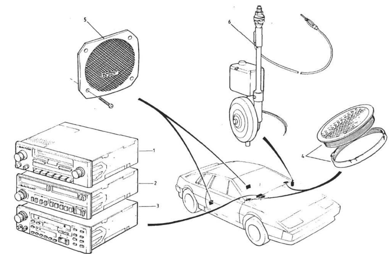
TURBO
17.27A
LHD SHOWN
| ILLUS NO. | DESCRIPTION |  PART NUMBER PART NUMBER | QUANTITY | MAY 1991REMARKS | |
| RHD | LHD | ||||
| 015 | Locking Plate, Pantograph Arm | A085U4790K | 1 | with p/g swivel joint > | |
| " " " " | B082M4258F | 1 | with p/g ball joint > | ||
| " " " " | A085U4791K | 1 | with p/g swivel joint >'Bolt-on' | ||
| " " " " | B082M4257F | 1 | with p/g ball joint > Wiper Arm | ||
| 016 | Screw, Locking Plate to Body | A075W5040Z | 1 | 1 | with p/g swivel joint > |
| Screw, Locking Plate to Body | A075W5040Z | 2 | 2 | with p/g ball joint > | |
| 017 | Bracket, Downstop | A079M4034K | 1 | 1 | |
| 018 | Screw, Downstop Fixing | A075W5040Z | 2 | 2 | |
| Wiper Arm Assembly | A079M4000F | 1 | ) | ||
| Wiper Arm Assembly | A079M4033F | 1 | )'Push-on' Wiper Arm | ||
| Bezel | A079M6085F | 1 | 1 | ) | |
| 020 | Wiper Arm Assembly | A085M4154F | 1 | > | |
| Wiper Arm Assembly | A085M4155F | 1 | >'Bolt-On' Wiper Arm with Pantograph | ||
| Washer, Wiper Arm Nut | A089M6038F | 1 | 1 | > Arm Swivel Joint | |
| Adaptor Plate, Wiper Arm | A082U6207F | 1 | 1 | Converts Swivel Joint to Ball Joint | |
| Wiper Arm Assembly | B082M4242J | 1 | ) | ||
| Wiper Arm Assembly | B082M4243F | 1 | )'Bolt-On' Wiper Arm with Pantograph | ||
| Washer, Wiper Arm Nut | A089M6038F | 1 | 1 | ) Arm Ball Joint | |
| 022 | Wiper Blade | A079M6015F | 1 | 1 | |
| 023 | Grommet, Washer Tubing | X036B6150Z | 1 | 1 | |
| 024 | Washer Pump & Reservoir Assembly | A079M6010F | 1 | 1 | |
| 025 | Mounting Bracket, Washer Reservoir | A075M6069Z | 1 | 1 | |
| 026 | Screw, Washer Brkt. to Body | A075W5014F | 3 | 3 | |
| 027 | Washer, Washer Brkt. to Body | A075W4014Z | 3 | 3 | |
| 028 | Washer Tubing, 4mm | A050M6164V | A/R | A/R | |
| 029 | Twin Jet, Windscreen Washer | A082M6176F | 1 | 1 | |
| Turbo 17.21APage 2 | |||||
| d4p65 | |||||

| ILLUS NO. | DESCRIPTION |  PART NUMBER PART NUMBER | QUANTITY |  REMARKS REMARKS | |
| ALL | |||||
| 17.27A | |||||
| 5 | Speaker, Rear, 25WCable, Short, Rear SpeakerCable, Long, Rear SpeakerLoom, Rear SpeakersSpeaker, Rear, EurotechGrille, Rear Speaker, with BadgeBadge, 'Lotus', Speaker GrilleCable Assembly, Rear SpeakersAerial, Electric, External FitRelay, Electric Aerial | A082M6231FC082M4118FC082M4119FA082M4589KA089M6079FA089M6080FA089U1725HA082M4640KA082M6149FA083M6321F | lpr11111222111 | Blaupunkt) )Routed Along SillRouted Along Tunnel) )Clarion Radio) )Nat. Panasonic, Motorola, Sparkomatic For A082M6149F | |
| 6 | Aerial, Electric, Internal FitJump Harness, AerialJump Harness, Ignition FeedJump Harness, Aerial/RadioHarness, Radio Feed | A082M6271FA082M4145CA082M4141CB082M4142CA082M4577F | 111111 | (See S/B 1984/10) )With Nat. Panasonic Radio) )Motorola, Sparkomatic, Blaupunkt | |
| d4p69 | Turbo 17.27APage 2 | ||||

| ILLUSNO. | DESCRIPTION |  PART NUMBER PART NUMBER | QUANTITY | MAY 1991REMARKS | |
| ALL | |||||
| 001 | Earth Bond, LH Door to Scuttle Beam | B082M4171F | 1 | ||
| 002 | Earth Bond, RH Door to Scuttle Beam | B082M4172F | 1 | ||
| 003 | Setscrew, M6 x 20, Bond to Door Beam | A075W1030Z | 2 | ||
| 007 | Foil, Screening | A065M6008V | 5m | ||
| 008 | Earth Bond, Chassis to Bulkhead | A082M4175F | 1 | ||
| 009 | Earth Braid, Engine to Chassis | A082M4210F | 1 | ||
| Capacitor, 2 mf, Ignition Coil | A075M6096Z | 1 | |||
| Capacitor, 1 mf, Fuel Pump | A075M6097Z | 1 | |||
| 012 | Capacitor, 1 mf, Stop Switch | A074M6008Z | 1 | ||
| 013 | Capicitor, 1 mf, Voltage Stabiliser | A075M6100Z | 1 | ||
| Choke, Voltage Stabiliser | X050M6107Z | 1 | |||
| 015 | Earth Lead, Timing Belt Tensioner | A082M4209F | 1 | ||
| 016 | Earth Bond, Seat & Tanks to Chassis | A079M4094F | 4 | ||
| Earth Bond, Electric Aerial | A079M4091F | 1 | |||
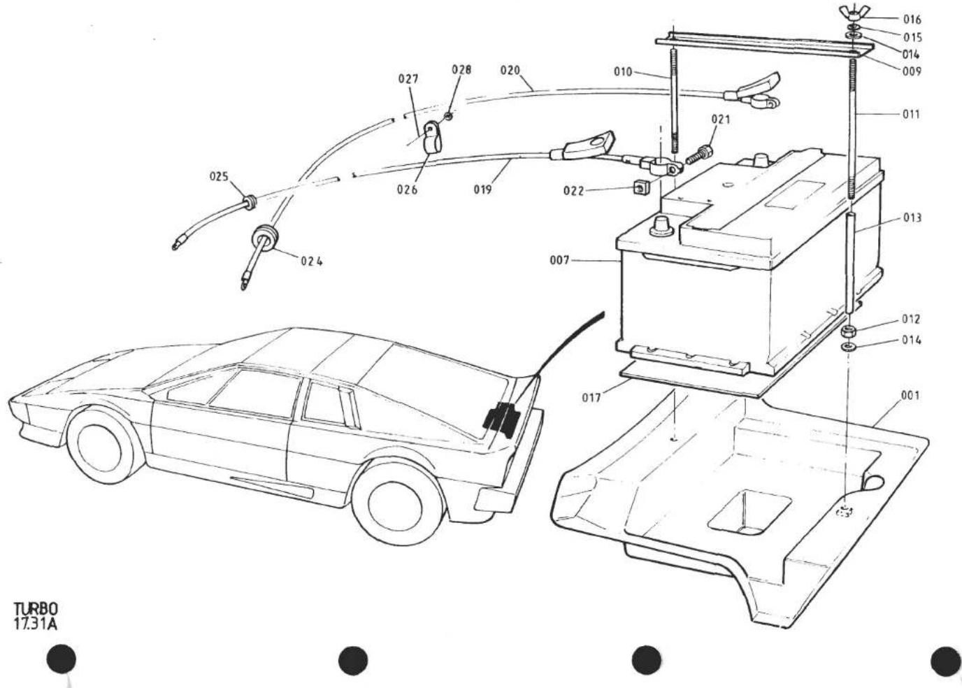
| ILLUS NO. | DESCRIPTION | PART NUMBER | QUANTITY | REMARKS | |
| ALL | |||||
| 17.31A | |||||
| 001 | Tray, Battery Carrier | A085B4359K | 1 | ||
| Battery, Chloride, Type 362 | A076M6004F | 1 | R/B A082M6214F | ||
| Battery, Chloride, Type 385 | A082M6214F | 1 | |||
| 007 | Battery, Tungstone, Type 065 Maintenance Free | A082M6169F | 1 | ||
| Battery, Tungstone, Type 088 Low Maintenance | A082M6284F | 1 | '87 M.Y. on) | ||
| Clamp Plate, Battery Retention | A082U4697K | 1 | |||
| Bolt, M8 x 35, Battery Retention | A075W2038Z | 1 | )For Bolt Fixing) | ||
| Bolt, M8 x 100, Battery Retention | A075W2049Z | 1 | |||
| Washer, Flat, Battery Retention | A075W4020Z | 2 | |||
| 009 | Clamp Plate, Battery Retention | A079U4471K | 1 | >Prior '87 M.Y. | |
| Clamp Plate, Battery Retention | A085U5115F | 1 | >'87 M.Y. on) | ||
| 010 | Stud, Short, Battery Retention | A085M4166F | 1 | > | |
| 011 | Stud, Long, Battery Retention | A085M4167F | 1 | > | |
| 012 | Nut, M6, Stud Retention | A075W3020Z | 2 | > For Stud Fixing | |
| 013 | Sleeving, Battery Stud | A085M6172V | 270mm | > | |
| 014 | Washer, Flat, Battery Stud | A075W4013Z | 4 | > | |
| 015 | Washer, Spring, Battery Stud | A075W4035Z | 4 | > | |
| 016 | Wing Nut, M6, Battery Retention | A075W3033Z | 2 | > | |
| 017 | Pad, Battery | A085M4168F | 1 | ||
| 019 | Battery Cable, Positive | A082M4107F | 1 | With Exide/Chloride Battery | |
| Battery Cable, Positive | A082M4157F | 1 | With Tungstone Battery | ||
| 020 | Battery Cable, Negative | A082M4108F | 1 | With Exide/Chloride Battery | |
| Battery Cable, Negative | A082M4158F | 1 | With Tungstone Battery | ||
| 021 | Bolt, 5/16" BSW, Battery Terminal | A082M6201F | 2 | ||
| 022 | Nut, 5/16" BSW, Battery Terminal | A082M6202F | 2 | ||
| 024 | Grommet, Battery Cable/Harness | A075P6021F | 3 | ||
| 025 | Grommet, Pos. Cable | A079U6033F | 1 | With Exide/Chloride Battery | |
| Grommet, Pos. Cable | X036J6026F | 1 | With Tungstone Battery | ||
| 026 | 'P' Clip, Battery Lead Securing | A075W6200Z | 1 | ||
| 027 | Pop Rivet 'P' Clip | A075W6092Z | 1 | ||
| 028 | Washer, Pop Rivet | A075W4001Z | 1 | ||
| Turbo 17.31A | |||||
| d4p67 | |||||

TURBO 18.01A


| ILLUS NO. | DESCRIPTION |  PART NUMBER PART NUMBER | QUANTITY | MAY 1991REMARKS | |
| RHD | LHD | ||||
| 18.01A | |||||
| 001 | Heater Assembly | A082P4168K | 1 | )Inc. Heater Matrix, Evaporator | |
| Heater Assembly | A082P4167K | 1 | )(A/C Only), Vac. Valves, | ||
| Heater/Air Conditioning Assembly | A082P4206K | 1 | )Control Cables, Rotary | ||
| Heater/Air Conditioning Assembly | A082P4205K | 1 | )Controls | ||
| Case, Upper | A079P4154K | 1 | Heater Only | ||
| Case, Upper | A079P4136K | 1 | Air Conditioning | ||
| Case, Upper | A079P4155K | 1 | Heater Only | ||
| 003 | Case, Upper | B079P4108K | 1 | Air Conditioning | |
| Case, Lower | A079P4156K | 1 | Heater Only | ||
| Case, Lower | A079P4137J | 1 | Air Conditioning | ||
| Case, Lower | A079P4157K | 1 | Heater Only | ||
| Case, Lower | A079P4109K | 1 | Air Conditioning | ||
| 009 | Setscrew, M6 x 12, Case to Mtg. Brkt. | A075W1027Z | 2 | 2 | |
| 010 | Washer, Flat, Case to Mtg. Brkt. | A075W4013Z | 2 | 2 | |
| 011 | Mounting Bracket, Case to Tunnel | A079P4096K | 1 | 1 | |
| 012 | Pop Rivet, Mtg. Brkt. to Tunnel | A075W6091Z | 2 | 2 | |
| 013 | Bush, Flap Pivot, Inner | A089P0268F | 4 | 4 | |
| 014 | Bush, Flap Pivot, Outer | A075P6064F | 4 | 4 | |
| 015 | Closing Panel | A079P4112K | 1 | 1 | |
| 016 | Screw, Closing Panel to Case | A075W5032Z | 2 | 2 | |
| 017 | Drain Adaptor, Main Case | A079P4106K | 1 | 1 | |
| 018 | Drain Tube, 5/8" PVC | A075U6083V | 0.4m | 0.4m | |
| 019 | Screw, Upper/Lower Case Fix | A075W5032Z | 9 | 9 | |
| 021 | Hose Clip, 16-25mm, Drain Tube | A079K6018F | 1 | ||
| d4p70 | Turbo 18.01A | ||||

| ILLUS NO. | DESCRIPTION |  PART NUMBER PART NUMBER | QUANTITY | MAY 1091REMARKS | |
| RHD | LHD | ||||
| Evaporator | A079P4139F | 1 | |||
| 001 | Evaporator | A079P4080F | 1 | ||
| 002 | Foam, Open Mesh | A075P0206F | 1 | 1 | |
| 003 | Elbow Adaptor | A079P6017F | 1 | ||
| 004 | Expansion Valve | A079P6012F | 1 | 1 | |
| 005 | Flare Gasket, 10.4mm | A082P4241F | 1 | 2 | Exp. Valve/Elbow/Evaporator |
| 006 | Receiver Drier | A079P6011F | 1 | 1 | |
| 007 | Bracket, Receiver Drier | A075P0089F | 1 | 1 | R/B A089P0278F |
| Bracket, Receiver Drier | A089P0278F | 1 | 1 | ||
| 008 | Bolt, M6 x 50, Bracket Clamping | A075W2032Z | 1 | 1 | Use with Bracket A075P0089F |
| Bolt, M6 x 30, Bracket Clamping | A075W2028Z | 1 | 1 | Use with Bracket A089P0278F | |
| 009 | Nut, Nyloc, M6, Brkt. Clamping | A075W3009Z | 1 | 1 | |
| 010 | Setscrew, M6 x 20, Brkt. to Body | A075W1030Z | 2 | 2 | |
| 011 | Washer, Flat, Brkt. to Body | A075W4015Z | 2 | 2 | |
| 012 | Washer, 25mm O/D, Brkt to Body | A075W4017Z | 2 | 2 | |
| 013 | Nut, Nyloc, M6, Brkt. to Body | A075W3009Z | 2 | 2 | |
| Hose, Receiver/Drier to Exp. Valve | A079P4135F | 1 | |||
| 014 | Hose, Receiver/Drier to Exp. Valve | A079P4077F | 1 | ||
| Hose, Evaporator to Compressor | A082P4204F | 1 | Dry Sump Engine | ||
| Hose, Evaporator to Compressor | A079P4134F | 1 | Wet Sump Engine | ||
| Hose, Evaporator to Compressor | A082P4203F | 1 | Dry Sump Engine | ||
| 015 | Hose, Evaporator to Compressor | A079P4078F | 1 | Wet Sump Engine | |
| 016 | Flare Gasket, Hose to Evaporator | A082P4242F | 1 | 1 | 15.7mm |
| Hose, Compressor to Condenser | A082P4202F | 1 | Dry Sump Engine | ||
| Hose, Compressor to Condenser | A082P4232F | 1 | Wet Sump Engine | ||
| Hose, Compressor to Condenser | A082P4201F | 1 | Dry Sump Engine | ||
| 017 | Hose, Compressor to Condenser | A082P4234F | 1 | Wet Sump Engine | |
| Heatshield Wrap, Discharge Hose | A082P4235F | 1 | Dry Sump Engine | ||
| Grommet, Fridge Hose/Engine Bay (Black) | A075P6021Z | 2 | 2 | )As Fitted | |
| Grommet, Fridge Hose/Engine Bay (Grey) | A082P6045F | 2 | 2 | ) | |
| 018 | Hose, Condenser to Receiver/Drier | A082P4170F | 1 | 1 | |
| 019 | 'O' Ring, ‡", Condenser Inlet | A075P6084F | 1 | 1 | |
| 020 | 'O' Ring, 3/8", Condenser Outlet | A075P6083F | 1 | 1 | |
| 021 | Plate, Grommet | B079P4084K | 1 | 1 | Turbo 18.03A |
| 023 | Grommet, Fridge Hoses/Bulkhead | A046K6001Z | 2 | 2 | Page 1 |
| d4p7l | |||||
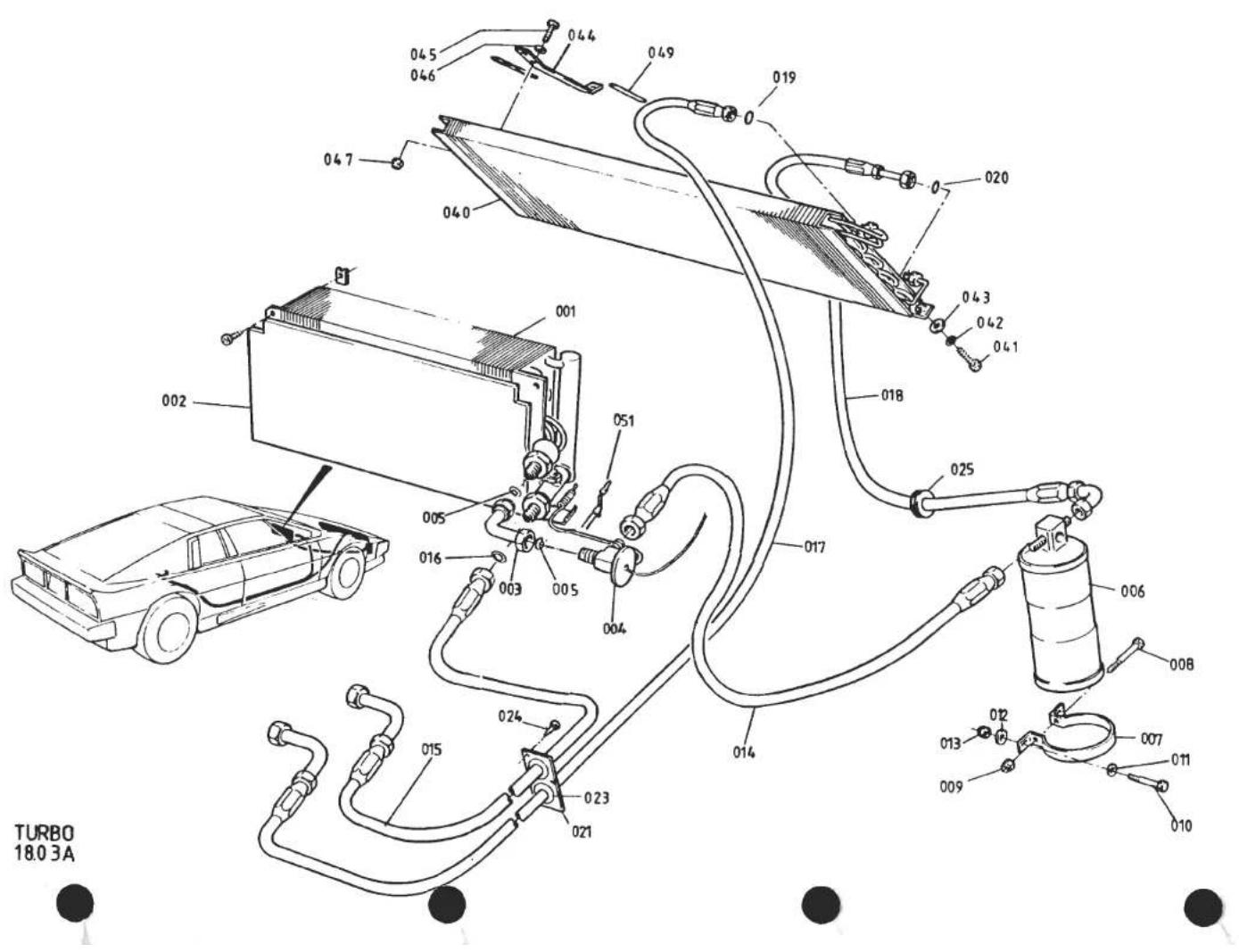
| ILLUS NO. | DESCRIPTION |  PART NUMBER PART NUMBER | QUANTITY | REMARKS | |
| RHD | LHD | ||||
| 18.03A | |||||
| 024 | Screw, Grommet Plate Fixing | A075W5015F | 4 | 4 | |
| 025 | Grommet, Fridge Hoses | A075P6021K | 4 | 5 | |
| 040 | Condenser | C082P4160F | 1 | 1 | |
| Foam Strip, Condenser to Radiator | A075B6015V | 0.5m | 0.5m | ||
| 041 | Setscrew, M8 x 20, Condenser to Duct | A075W1038Z | 2 | 2 | |
| 042 | Washer, Shakeproof, Condenser to Duct | A075W4048Z | 2 | 2 | |
| 043 | Washer, 25mm O/D, Condenser to Duct | A075W4021Z | 2 | 2 | |
| 044 | Bracket, Condenser Support | A082P4163K | 2 | 2 | )Prior to '87 M.Y. |
| Bracket, Condenser Support | A082P4251F | 2 | 2 | )'87 M.Y. On | |
| 045 | Setscrew, M6 x 16, Brkt. to Condenser | A075W1028Z | 4 | 4 | |
| 046 | Washer, Flat, Brkt. to Condenser | A075W4013Z | 4 | 4 | |
| 047 | Nut, Nyloc, M6, Brkt. to Condenser | A075W3009Z | 4 | 4 | |
| 049 | Neoprene Strip, Anti-Chafe | B075U6054V | 640 | 320 | mm |
| Tape, Non-Drip, Evaporator Connections | A075P6086V | A/R | A/R | ||
| 051 | Thermistor | A085P6038F | 1 | 1 | Strapped to Evaporator |
| Turbo 18.03APage 2 | |||||
| d4p72 | |||||

| ILLUS NO. | DESCRIPTION |  PART NUMBER PART NUMBER | QUANTITY | MAY 199i REMARKS | |
| ALL | |||||
| 18.05A | |||||
| 1 | Heater Matrix | A075P6055Z | 1 | ||
| 2 | Foam, Heater Matrix to Case | A075P0194K | 2 | ||
| 5 | Water Valve | A075P6060F | 1 | ||
| 6 | Bracket, Water Valve Mounting, RHD | A079P4144K | 1 | ||
| Bracket, Water Valve Mounting, LHD | A079P4104K | 1 | |||
| 7 | Setscrew, Bracket to Water Valve | A075W1000Z | 1 | ||
| 8 | Nut, Bracket to Water Valve | A075W3000Z | 1 | ||
| Bracket, Cable Abutment | A079P4105K | 1 | ) Prior to Spot Welded Abutment Bracket | ||
| Clip, Cable Abutment | A075W6117F | 1 | |||
| Setscrew, Abutment Bracket to Valve | A075W1000Z | 2 | |||
| Nut, Abutment Bracket to Valve | A075W3000Z | 2 | |||
| Clamp, Cable to Water Valve | A082P4244F | 1 | Used with Spot Welded Abutment Bracket | ||
| 11 | Hose, Capillary Line Protection | A050M6165Z | 250mm | ||
| 12 | Clip, Capillary Line | A075W6223F | 2 | ||
| 15 | Hose, Water Valve to Matrix | A079P4142F | 1 | ||
| 16 | Hose Clip | A079K6018K | 2 | ||
| 17 | Hose, Valve Inlet/Matrix Outlet | A079P4056F | 2 | ||
| 18 | Hose Clip | A079K6018K | 4 | ||
| 19 | Grommet, Hoses Through Body | A075P6021Z | 2 | ||
| 20 | Connector Pipe, Heater Hose | B075K0111F | 2 | ||
| 21 | Elbow Hose, Heater Pipe, Front | A075P0189F | 2 | ||
| 22 | Hose Clip, Elbow Hose | A079K6018K | 4 | ||
| 25 | Pipe, Heater Water, Through Chassis | A082P4200F | 2 | ||
| 26 | Grommet, Pipes/Chassis | A079K6004F | 4 | ||
| 27 | Hose, Heater Feed & Return | A079P4056F | 2 | ||
| 28 | Hose Clip, Feed & Return Hose | A079K6018K | 4 | ||
| 30 | Transfer Pipe, Heater Pipe to Plenum | B910E1546K | 1 | ||
| 31 | 'p' Clip, Transfer Pipe to Plenum | A910E6490F | 2 | ||
| 32 | Elbow Hose, Water Rail to Transfer Pipe | A075P0189F | 1 | ||
| 33 | Hose Clip, Elbow Hose | A079K6018F | 2 | ||
| Turbo 18.05A | |||||
| d4pl6 | |||||
TURBO 18.07A


| ILLUS NO. | DESCRIPTION |  PART NUMBER PART NUMBER | QUANTITY | MAY 1991REMARKS | |
| ALL | |||||
| 1 | Blower Motor & Fan Assembly, Top | A075P6056F | 1 | CCW Rotation Viewed Motor End | |
| 2 | Blower Motor & Fan Assembly, Bottom | A075P6058F | 1 | CW Rotation Viewed Motor End | |
| 3 | Clamp, Motor to Housing | A079P4091K | 6 | ||
| 4 | Setscrew, M5 x 20, Motor Clamp | A075W1025Z | 6 | ||
| 5 | Washer, Motor Clamp Screw | A075W4011Z | 6 | ||
| 6 | Jacknut, M5, Motor Clamp Screw | A076W3043F | 6 | ||
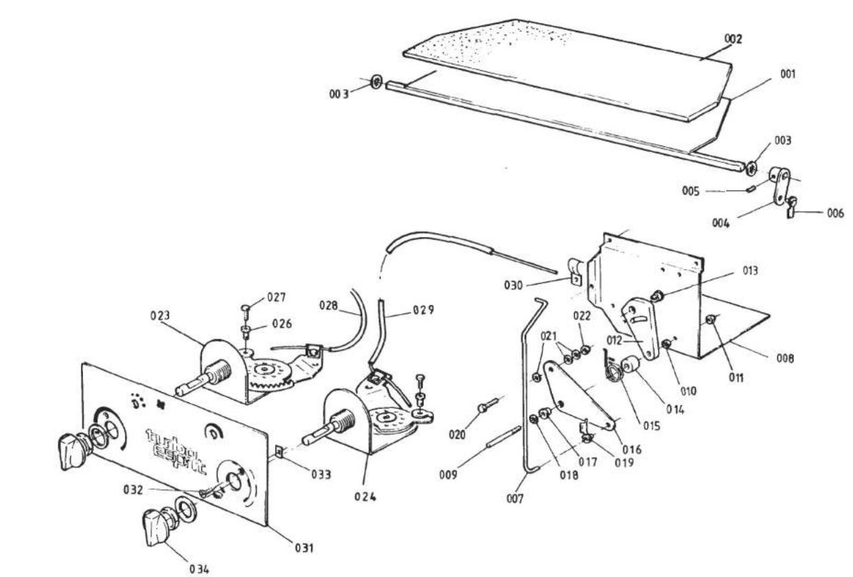
TURBO 18.0 9A


| ILLUSNO. | DESCRIPTION |  PART NUMBER PART NUMBER | QUANTITY | MAY 1991REMARKS | |
| RHD | LHD | ||||
| 001 | Flap, Defrost/Footwell | B079P4017F | 1 | ||
| Flap, Defrost/Footwell | A079P4175F | 1 | |||
| 002 | Foam, Defrost/Footwell Flap | B036B6197V | * | * | 300 x 100mm |
| 003 | Clip, Flap Shaft Ends | A075W6173F | 2 | 2 | |
| 004 | Lever, Defrost/Footwell Flap Shaft | A079P4101F | 1 | 1 | |
| 005 | Grubscrew, Lever to Shaft | A075W7023Z | 1 | 1 | |
| 006 | Clip, Rod to Lever | A075U6033F | 1 | 1 | |
| 007 | Rod, Defrost/Footwell Flap Operating | C079P4143F | 1 | 1 | |
| 008 | Control Plate | C082P4188K | 1 | ||
| Control Plate | C082P4185K | 1 | |||
| 009 | Stud, 10 UNF, Cam/Lever Pivot | A075P0225F | 1 | 1 | |
| 010 | Nut, Plain, 10 UNF, Pivot Stud | A075W3013Z | 1 | 1 | |
| 011 | Nut, Nyloc, 10 UNF, Pivot Stud | A075W3000Z | 1 | 1 | |
| 012 | Cam, Vacuum Valve Operating | A075P0173F | 1 | 1 | |
| 013 | Trunnion, Cable to Cam | B075W6121F | 1 | 1 | |
| 014 | Spacer, Lever to Cam | A075P0229F | 1 | 1 | |
| 015 | Spring, Cam Return | B075P0176F | 1 | ||
| Spring, Cam Return | A079P4103F | 1 | |||
| 016 | Lever, Bell Crank, Defrost Flap | A082P4184K | 1 | 1 | |
| 017 | Bush, Lever Pivot | A075P0162F | 1 | 1 | |
| 018 | Clip, Lever Pivot | A075W6173F | 1 | 1 | |
| 019 | Clip, Lever to Flap Rod | A075U6033F | 1 | 1 | |
| 020 | Setscrew, 10 UNF x 3/8", Cam Operating | A075W1000Z | 1 | 1 | |
| 021 | Washer, Cam Setscrew | A075W4011Z | 3 | 3 | |
| 022 | Nut, Nyloc, 10 UNF, Cam Setscrew | A075W3000Z | 1 | 1 | |
| 023 | Rotary Control, Temperature | B082P4195J | 1 | 1 | |
| 024 | Rotary Control, Air Distribution | B082P4196Z | 1 | 1 | |
| 026 | Nipple/Trunnion, Rotary Control | A074K6001Z | 2 | 2 | |
| 027 | Screw, Cable to Control | B074K6002F | 2 | 2 | |
| 028 | Control Cable, Water Valve | A082P4189F | 1 | 1 | |
| 029 | Control Cable, Air Distribution | A082P4190F | 1 | 1 | |
| 030 | Clamp, Cable to Control Plate | A082P4244F | 1 | 1 | |
| Turbo 18.09APage 1 | |||||
| d4p74 | |||||
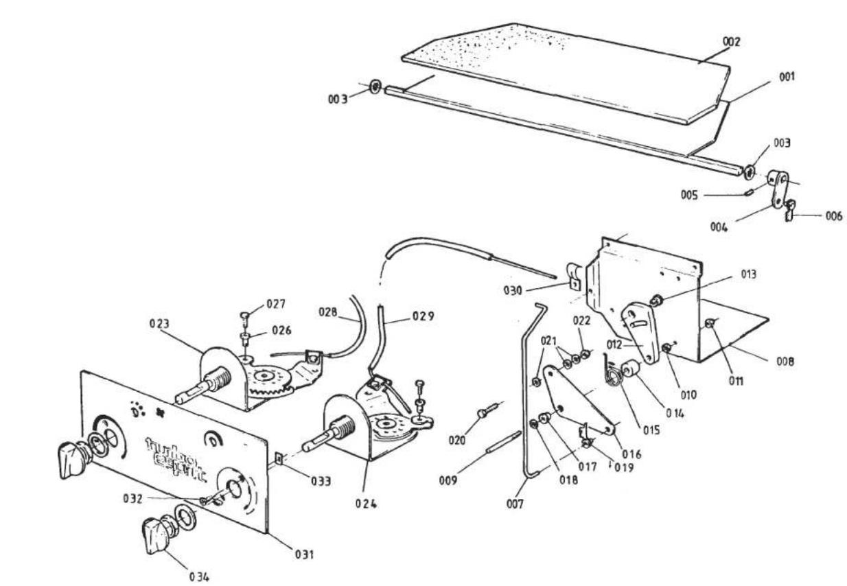
TURBO
18.09A


| ILLUS NO. | DESCRIPTION |  PART NUMBER PART NUMBER | QUANTITY | MAY 1991REMARKS | |
| RHD | LHD | ||||
| 18.09A | |||||
| 031 | Graphic Control Panel, with A/C | A082P4197F | 1 | 1 | With Essex Turbo Cockpit Unit |
| Graphic Control Panel, with A/C, Long | A082P4164F | 1 | 1 | With Hole for Compressor Indicator LightFor Face Mounted Radio, or No Radio | |
| Graphic Control Panel, with A/C, Long | B082P4164F | 1 | 1 | With No Hole for Compressor Indicator LightFor Face Mounted Radio, or No Radio | |
| Graphic Control Panel, with A/C, Short | A082P4210F | 1 | 1 | With Hole for Compressor Indicator LightFor Box Mounted Type Radio | |
| Graphic Control Panel, with A/C, Short | A082P4238F | 1 | 1 | With No Hole for Compressor Indicator LightFor Box Mounted Type Radio | |
| Graphic Control Panel, Heater Only, Long | A082P4193F | 1 | 1 | For Face Mounted Radio or No RadioCut Short for Box Mounted Type Radio | |
| 032 | Screw, No.6 x 1⁄2" s/t, Panel Fix | A075W5020Z | 2/4 | 2/4 | |
| 033 | Spire Nut, Panel Fix | A075W6014Z | 2/4 | 2/4 | |
| 034 | Knob, Rotary Controls | A082P6023F | 2 | 2 | R/B A082P4253K |
| Knob, Rotary Controls | A082P4253K | 2 | 2 | ||
| d4p80 | Turbo 18.09APage 2 | ||||

| ILLUS NO. | DESCRIPTION |  PART NUMBER PART NUMBER | QUANTITY | MAY 1991REMARKS | |
| RHD | LHD | ||||
| Flap, Mode | A079P4176F | 1 | |||
| 001 | Flap, Mode | B079P4014F | 1 | ||
| 002 | Foam, Mode Flap | A079P4161K | 2 | 2 | |
| 003 | Clip, Flap Shaft Ends | A075W6173F | 2 | 2 | |
| 004 | Mounting Plate, Actuator Brkt. | B079P4093F | 1 | 1 | |
| Pop Rivet, Mtg. Plate to Case | A075W6071Z | 5 | 5 | ||
| 005 | Bracket, Vacuum Actuator Mtg. | A075P0170F | 1 | 1 | |
| Pop Rivet, Brkt to Plate | A075W6071Z | 4 | 4 | ||
| 006 | Vacuum Actuator, Mode/Fresh Air Flap | A075P6059F | 2 | 2 | |
| 007 | Rod, Actuator to Mode Flap | A075P0234F | 1 | 1 | |
| 008 | Locking Tab, Actuator to Rod | A079P4149K | 1 | 1 | |
| 009 | Clip, Rod to Mode Flap Lever | A075U6033F | 1 | 1 | |
| 010 | Lever, Flap Operating | A079P4102F | 1 | 1 | |
| 011 | Vacuum Switch, Mode/Fresh Air Flaps | A075P6062F | 2 | 2 | |
| 012 | Bracket, Vac. Switch Securing | A075P0172F | 2 | 2 | |
| 013 | Screw, No. 6 x 1/4", Brkt. to Plate | A075W5010Z | 4 | 4 | |
| 014 | Elbow Connector | A075P6079F | 7 | 7 | |
| 014A | 'T' Piece, Vacuum Pipes | A075P6081F | 1 | 1 | |
| 015 | Vacuum Pipe | A075P6068V | 6m | 6m | |
| 016 | Elbow Connector, Unequal Bore | A075P6069F | 2 | 2 | |
| 017 | Bracket, Vac. Actuator to Bulkhead | A079P4097K | 1 | 1 | |
| 018 | Screw, No. 6 x 3/4", Brkt. to Bulkhead | A075W5028Z | 4 | 4 | |
| 019 | Spire Nut, Brkt. to Bulkhead | A075W6013Z | 4 | 4 | |
| 020 | Clevis Pin, Actuator to Flaps | A075W6027Z | 1 | 1 | |
| 021 | Washer, Clevis | A075W4001Z | 4 | 4 | |
| 022 | Split Pin, Clevis Retention | A075W6005Z | 1 | 1 | |
| 023 | Flap, Fresh Air Intake | A079P4099F | 1 | 1 | |
| Flap, Air Re-Circulation | A079P4138F | 1 | With Air Conditioning | ||
| 025 | Flap, Air Re-Circulation | A079P4098F | 1 | With Air Conditioning | |
| 026 | Lever, Fresh Air/Re-Circ. Flap | A079P4102F | 1/2 | 1/2 | 2 With A/C |
| 026A | Grub Screw, Lever to Flap Shaft | A075W7023Z | 3 | 3 | |
| 027 | Bracket, Fresh Air/Re-Circ. Flap Support, RH | A079P4141K | 1 | 1 | |
| 027A | Bracket, " " " " " " " , LH | A079P4087K | 1 | 1 | Turbo 18.11APage 1 |
| d5pl | |||||
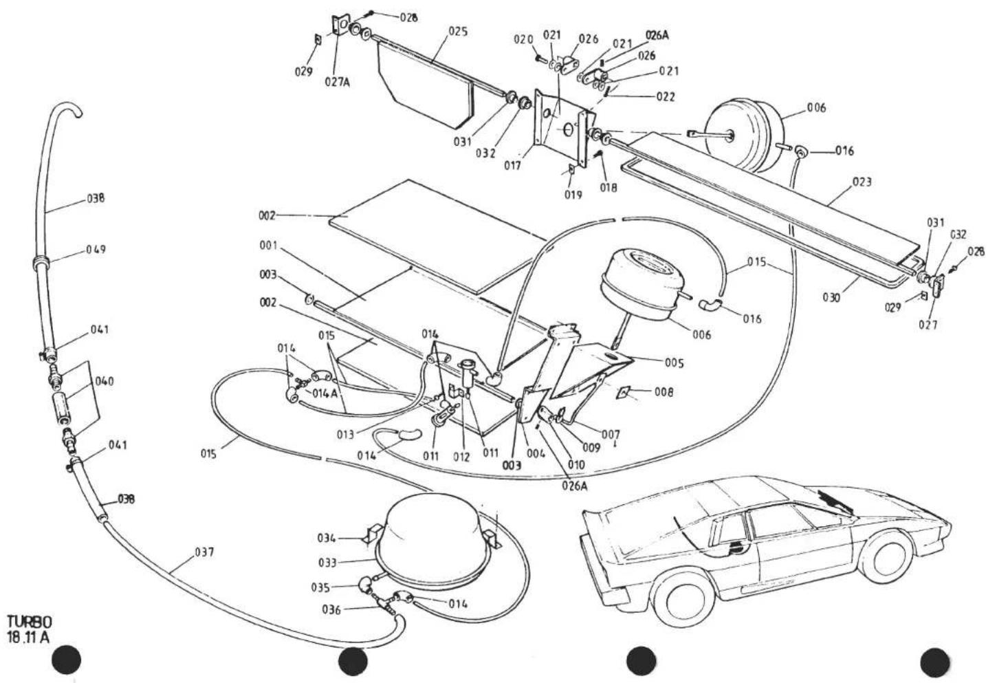
| ILLUSNO. | DESCRIPTION | PART NUMBER | QUANTITY | REMARKS | |
| RHD | LHD | ||||
| 18.11A | |||||
| 028 | Screw, No. 6 x 3/4", Brkt to Bulkhead | A075W5028Z | 4 | 4 | |
| 029 | Spire Nut, Brkt. to Bulkhead | A075W6013Z | 4 | 4 | |
| 030 | Foam Seal, Fresh Air Flap | A036B6213V | lm | lm | |
| 031 | Pivot Bush, Inner | A089P0268F | 2/4 | 2/4 | 4 With A/C ) |
| 032 | Pivot Bush, Outer | A075P6064F | 2/4 | 2/4 | 4 With A/C ) |
| 033 | Vacuum Reservoir | A079P6014F | 1 | 1 | |
| Pad, Anti-Vibration, Reservoir Mounting | A082P4256C | 1 | 1 | ||
| 034 | Bracket, Reservoir Fixing | A079P4090K | 3 | 3 | |
| Setscrew, M6 x 16, Brkt. Fixing | A075W1029Z | 3 | 3 | )R/B A075W5014F ) | |
| Nut, Nyloc, M6, Brkt. Fixing | A075W3009Z | 3 | 3 | ||
| Screw, s/t, Bracket, Fixing | A075W5014Z | 3 | 3 | ||
| 035 | Straight Connector, Reservoir/'T' Piece | A075P6080F | 1 | 1 | |
| 036 | 'T' Piece | A079P6019F | 1 | 1 | |
| 037 | Tubing, Vacuum, Nylon | A026B0130Z | A/R | A/R | |
| Connector Hose, PVC | A075U6080F | A/R | A/R | R/B A075L6043V ) | |
| 038 | Vacuum Hose, Rubber | A075L6043V | A/R | A/R | |
| Non-Return Valve, 'In Line' | A075U0561Z | 1 | 1 | R/B A089P0714J ) | |
| 040 | Non-Return Valve, 'In Line' | A089P0714J | 1 | 1 | On pre '85 Turbo, Replaces NRV In ) |
| Manifold Balance Rail. See SB 1982/14) | |||||
| 041 | Hose Clip | A079M6132F | 3 | 3 | |
| 049 | Grommet, Engine Bay Wall | X036B6010Z | 1 | 1 | |
| * Prior to '87 M.Y. | |||||
| Turbo 18.11A | |||||
| Page 2 | |||||
| d5p2 | |||||
LHD ILLUSTRATED
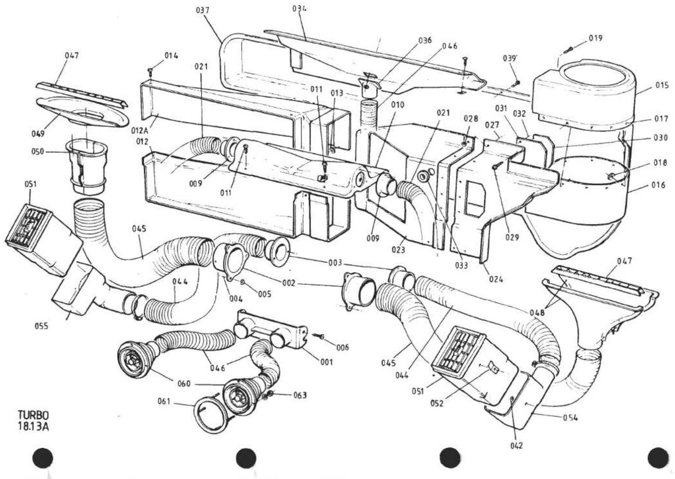
| ILLUSNO. | DESCRIPTION |  PART NUMBER PART NUMBER | QUANTITY | MAY 1991REMARKS | |
| RHD | LHD | ||||
| Outlet Adaptor, Centre F.L.V. | A079P4118K | 1 | 1 | For Rectangular Centre Vents | |
| 001 | Outlet Adaptor, Centre F.L.V. | A085P4213K | 1 | 1 | For Round Centre Vents |
| 002 | Outlet Adaptor, Demist | A079P4119K | 2 | 2 | |
| 003 | Outlet Adaptor, Outer F.L.V. | A079P4120K | 2 | 2 | |
| 004 | Pop Rivet, Demist & Outer F.L.V. Adaptors | A075W6071Z | 12 | 12 | |
| 005 | Washer, Pop Rivet | A075W4001Z | 6 | 6 | |
| 006 | Screw, Centre F.L.V. Adaptor | A075W5032Z | 2 | 2 | |
| 009 | Outlet Adaptor, Footwell | A075P0105F | 2 | 2 | |
| 010 | Cover, Footwell Duct Take Off | A079P4117K | 1 | 1 | |
| 011 | Screw, No. 8 x 3/8", Cover to Case | A075W5032Z | 4 | 4 | |
| 012 | Scroll Extension | A079P4114K | 1 | 1 | RHD Upper, LHD Lower |
| 012A | Scroll Extension | A079P4113K | 1 | 1 | RHD Lower, LHD Upper |
| 013 | Washer, Scroll Extension | A075W4001Z | 9 | 9 | |
| 014 | Screw, Scroll Extension | A075W5032Z | 7 | 7 | |
| 015 | Scroll, Blower Fan | A079P4110K | 1 | 1 | RHD Lower, LHD Upper |
| 016 | Scroll, Blower Fan | A079P4111K | 1 | 1 | RHD Upper, LHD Lower |
| 017 | Pop Rivet, Fan Scroll | A075W6071Z | 10 | 10 | |
| 018 | Washer, Pop Rivet | A075W4001Z | 10 | 10 | |
| 019 | Screw, Scroll to Scroll Extension | A075W5034Z | 2 | 2 | |
| Spire Nut | A075W6011Z | 2 | 2 | ||
| 021 | Ducting, 11", Footwell | A075P6066V | lm | lm | |
| Bulkhead Sealing Panel, Inboard | A082P4220K | 1 | |||
| 023 | Bulkhead Sealing Panel, Inboard | A082P4222K | 1 | ||
| Bulkhead Sealing Panel, Outboard | B082P4221K | 1 | |||
| 024 | Bulkhead Sealing Panel, Outboard | B082P4223K | 1 | ||
| 027 | Pop Rivet 1/8" Sealing Panel Joint | A075W6070F | 3 | 3 | |
| 028 | Washer, Sealing Panel Joint | A075W4001Z | 3 | 3 | |
| 029 | Screw, Sealing Panel Fixing | A075W5014Z | 6 | 6 | |
| 030 | Flap, Cabin Pressure Relief | A079P4131K | 1 | 1 | |
| 031 | Hinge, Pressure Relief Flap | A085P4231K | 1 | 1 | |
| 032 | Pop Rivet, Flap Fixing | A075W6071Z | 3 | 3 | |
| 033 | Grommet, Bulkhead Sealing Panel | X036B6150Z | 1 | 1 | Turbo 18.13APage 1 |
| d5p3 | |||||
LHD ILLUSTRATED

| ILLUS NO. | DESCRIPTION |  PART NUMBER PART NUMBER | QUANTITY | MAY 1991REMARKS | |
| RHD | LHD | ||||
| 18.13A | |||||
| Plenum Chamber | A079P4152K | 1 | |||
| 034 | Plenum Chamber | A079P4116K | 1 | ||
| 036 | Adaptor, Plenum to Drain Tube | A079P4173K | 1 | 1 | |
| Cover, Bulkhead | B082P4171K | 1 | |||
| 037 | Cover, Bulkhead | B082P4172K | 1 | ||
| Foam Strip, Cover to Body | A082U6067F | 2m | 2m | ||
| 039 | Screw, No. 6 x 1⁄2", Bulkhead Cover | A075W5015Z | 16 | 16 | |
| 044 | Ducting, 1 7/8", Outer F.L.V. | A079P6007V | A/R | A/R | |
| 045 | Ducting, 2 1/4", Demist | A079P4027V | A/R | A/R | |
| Ducting, 2", Centre F.L.V. | A079P4005V | A/R | A/R | With Rectangular Centre F.L.V.'s | |
| 046 | Ducting, 11⁄2", Centre F.L.V. | A075P6066V | A/R | A/R | With Round Centre F.L.V.'s |
| 047 | Outlet Vanes, Demist Vent | B079P4039F | 2 | 2 | |
| 048 | Demist Vent, Passenger Side | A079P4026K | 1 | 1 | |
| 049 | Demist Vent, Binnacle | A079P4064K | 1 | 1 | |
| 050 | Adaptor, Demist Vent to Hose | A079P4065K | 1 | 1 | |
| 051 | Face Level Vent, Outer | A075P6018Z | 2 | 2 | |
| 052 | Clip, Outer F.L.V. Retaining | C075P0112Z | 4 | 4 | |
| Pop Rivet, Clip to F.L.V. | A075W6086F | 4 | 4 | ||
| Washer, Pop Rivet | A075W4001F | 4 | 4 | ||
| 054 | Adaptor, 90°, F.L.V. to Ducting | B076P0132F | 1 | 1 | Passenger Side Vent |
| Adaptor, 90°, F.L.V. to Ducting | A075P0113Z | 1 | Driver's Side Vent | ||
| 055 | Adaptor, 90°, F.L.V. to Ducting | A075P0114Z | 1 | Driver's Side Vent | |
| Face Level Vent, Centre, Rectangular | A075P6018Z | 2 | 2 | ||
| Clip, Centre F.L.V. Retaining | A075P0115Z | 4 | 4 | ||
| Pop Rivet, Clip to F.L.V. | A075W6086F | 4 | 4 | ||
| Washer, Pop Rivet | A075W4001F | 4 | 4 | ||
| Adaptor, Straight, F.L.V. to Ducting | A079P4126K | 2 | 2 | Rectangular Centre F.L.V.'s | |
| 060 | Face Level Vent, Centre, Round | A085P6037F | 2 | 2 | |
| 061 | Retaining Ring, Round Vent | A085P4212K | 2 | 2 | Inc. In Trimmed Fascia |
| 063 | Nut, Nyloc, M3, Vent Fixing | A079W3060F | 8 | 8 | |
| Turbo 18.13APage 2 | |||||
| d5p4 | |||||
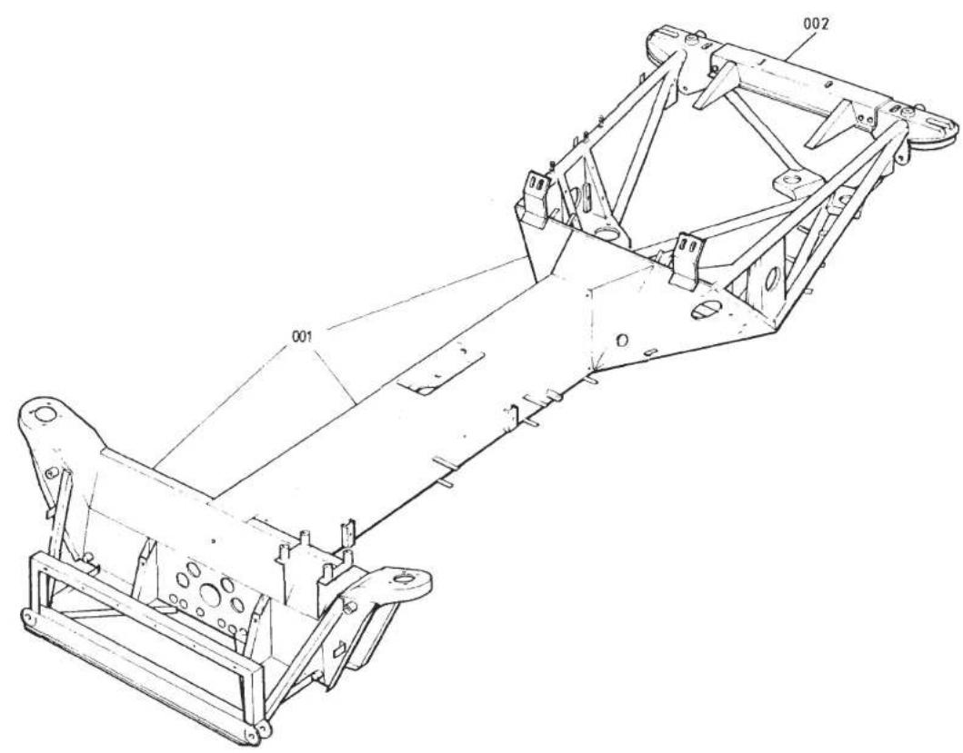
TURBO 30.01 A


| ILLUSNO. | DESCRIPTION |  PART NUMBER PART NUMBER | QUANTITY | MAY 1991REMARKS | |
| RHD | LHD | ||||
| 30.01A | |||||
| 001 | ChassisChassisChassisChassisChassisChassisChassisChassisChassisChassisChassisChassisChassisChassisChassisChassisChassisChassisChassisChassisChassisChassisChassisChassisChassisChassisChassisChassisChassisChassisChassisChassisChassisChassisChassisChassisChassisChassisChassisChassisChassisChassisChassisChassisChassisChassisChassisChassisChassisChassisCh之日起继续继续继续继续继续继续继续继续继续继续继续继续继续继续继续继续继续继续继续继续继续继续继续继续继续继续继续继续继续继续继续继续继续继续继续继续继续继续继续继续继续继续继续继续继续继续继续继续继续继续继续继续继续继续继续继续继续继续继续继续继续继续继续继续继续继续继续继续继续继续继续继续继续继续继续继续继续继续继续继续继续继续继续继续继续继续继续继续继续继续继续继续继续继续继续继续继续继续继续继续续 | G082A4160JA082A4218FB082A4218JB082A4234J #G082A4125JA082A4217FB082A4217JB082A4234J #B082A4152JB082A4236FA082A4237FA082A4238F | 1111111111111111111111111111111111111111111111111111111111111111111111111111111111111111111111111111 | Prior to '85 Model Year* †1985/'86 Model Year †'87 M.Y. on R/B B082A4234J +(B/Pipe Clamps)Prior to '85 Model Year* †1985/'86 Model Year †'87 M.Y. on R/B B082A4234J +(B/Pipe Clamps)*When replacing a pre '85 chassis, the following parts may also be required to fit the latest pre '85 specification Chassis dependent on VIN: Anti-Roll Bar & Fixings (see 31.01A) Rear Top Link Fixings (see 31.03A) Engine Mountings (see 40.01A)†Note When replacing a Pre'87 M.Y.Chassis, the oil cooler hoses must be run through the Chassis backbone with 190mm of edge protector AX75L6020V in the Chassis rear diaphragm, and 85mm of foam tube A082E6022V in the front crossmember.If a oil cooler thermostat is fitted, replace LH hose from thermostat to cooler with hose A082E4111F.Turbo 30.01A | |
| 002 | Rear CrossmemberClamp, Hose #Clamp, Pipe LH #Clamp, Pipe RH # | ||||
| d5p5 | |||||


| ILLUS NO. | DESCRIPTION |  PART NUMBER PART NUMBER | QUANTITY | MAY 1991REMARKS | |
| ALL | |||||
| 31.01A | |||||
| 12 | Front Hub Assembly (With Studs) | A082C4018F | 2 | This Page Prior to '85 Model YearFor '85 M.Y. Cars see 31.01B) | |
| Stud, Wheel | A079D6002H | 8 | )Compomotive Wheels | ||
| Front Hub | A082C4043F | 2 | BBS Wheels | ||
| Brake Disc | A075J0297F | 2 | Ground Finish. R/B C075J0297F in pairs | ||
| Brake Disc | C075J0297F | 2 | Non Directional Machined | ||
| 3456 | Bolt, 3/8" x 7/8" UNF | A075W1024F | 8 | > | |
| Washer, Spring 3/8" | A075W4067F | 8 | >Brake Disc to Hub | ||
| Wheel Bearing, Inner | A036C6042F | 2 | |||
| Wheel Bearing, Outer | A036C6041F | 2 | |||
| Oil Seal, Front Hub | A050C6002F | 2 | |||
| Stub Axle | A036C6040F | 2 | |||
| Nut, Nyloc, 9/16" | A075W3054F | 2 | ) | ||
| Washer, Plain | A036C6034F | 2 | )Stub Axle to Vertical Link | ||
| 78 | Nut, Castellated | A036C6010F | 2 | > | |
| Washer, 'D' | A050C6000F | 2 | >Hub to Stub Axle | ||
| Split Pin | A075W6176F | 2 | |||
| Hub Cap | A075C6004F | 2 | |||
| Vertical Link LH | A036C6043F | 1 | |||
| Vertical Link RH | A036C6044F | 1 | |||
| 910 | Plug, Lubrication, Vertical Link | A036C6035F | 2 | ||
| Steering Arm, RH | C075C0122F | 1 | |||
| Steering Arm, LH | C075C0123F | 1 | |||
| Caliper Mounting Plate RH | A082C4022F | 1 | |||
| Caliper Mounting Plate LH | A082C4023F | 1 | |||
| 11 | Sealing Ring | X050C6019F | 2 | Caliper Mounting Plate to Vertical Link | |
| Dust Shield LH | B075C0139F | 1 | |||
| Dust Shield RH | B075C0140F | 1 | |||
| d5p6 | Turbo (Prior '85 M.Y.) 31.01APage 1 | ||||
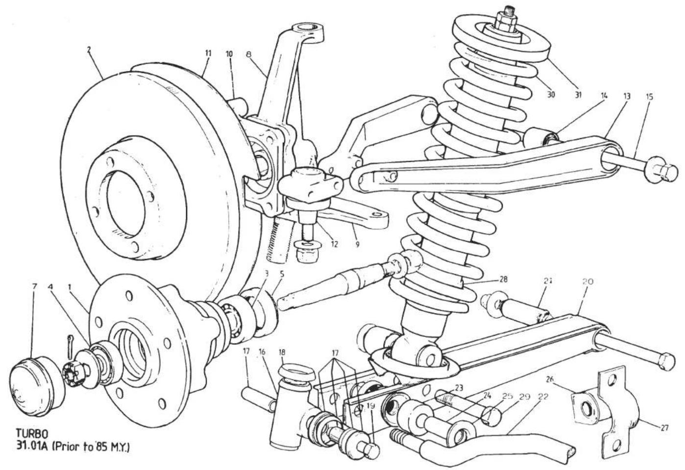


| ILLUS NO. | DESCRIPTION |  PART NUMBER PART NUMBER | QUANTITY | 1664 AYWREMARKS | |
| ALL | |||||
| 31.01A | |||||
| 12 | Bolt 5/16" x 3/4" UNFWasher, Spring, 8 mm | A075W1022FA075W4036F | 44 | This Page Prior to '85 Model YearFor '85 M.Y. Cars See 31.01B)Caliper Plate to Vertical Link> | |
| Bolt 3/8" x 1.1/4" UNFWasher, Spring, 10 mm | A075W1023FA075W4037F | 22 | |||
| Bolt, 3/8" x 2.1/4" UNFNut, Torgloc, 3/8" UNF | B075W2096FA075W3003F | 22 | |||
| Upper Ball JointNut, Torgloc, 7/16" UNFWasher, Plain | A036C6007FA075W3004FA075W4005F | 22 | |||
| Bolt, 8 x 100 mmBolt, 8 x 60 mmNut, Nyloc, MB | A075W2049FA075W2043FA075W3010F | 224 | |||
| Washer, Plain | A075W4020F | 4 | |||
| 13 | Wishbone Arm | E075C0130F | 4 | ||
| 14 | Pivot Bush, Wishbone | X036C6004F | 4 | ||
| 15 | Stud, Wishbone PivotNut, Nyloc 1⁄2" UNFLocknut, 1⁄2" UNFWasher, Wishbone PivotCover, Wishbone Stud AccessScrew, Cover Fixing | A075C0145FA075W3005F | 24 | ||
| A075W3017FA075C0149F | 28 | ||||
| A082B6057FA075W5011Z | 24 | ||||
| 16 | Lower Trunnion, RHLower Trunnion, LH | A036C6025FA036C6026F | 11 | ||
| 17 | Bush Kit, Lower Trunnion | A083C6012FA036C6047F | 22 | One Kit per Trunnion)Trunnion to Lower Link) | |
| 18 | Seal, Trunnion Top | A075W2010FA075W3004F | 22 | ||
| 19 | Bolt 7/16" UNFNut, 7/16" UNFWasher | A075W4005FA075W4005F | 22 | ||
| 20 | Lower Link, LHLower Link, RH | B082C4019FB082C4020F | 11 | Turbo (Prior '85 M.Y.) 31.01APage 2 | |
| d5p7 | |||||


| ILLUSNO. | DESCRIPTION |  |  |  | ||
| PART NUMBER | ALL | REMARKS | ||||
| 31.01A | ||||||
| 21 | Bush, Lower Link Pivot | A075C6000F | 2 | This Page Prior to '85 Model YearFor '85 M.Y. Cars See 31.01B)Lower Link to ChassisUp to VIN 82 D 126282 - 0410 exc. 0399 & 0400 | ||
| Bolt 1⁄2" x 6" UNF | A075W2015F | 2 | ||||
| Nut, Nyloc 1⁄2" UNF | A075W3005F | 2 | ||||
| Washer | A075W4007F | 2 | ||||
| 22 | Anti-Roll Bar | C082C4025F | 1 | |||
| Anti-Roll Bar | E082C4025F | 1 | From VIN 82 D 126382 - 0411 plus 0399 & 0400 | |||
| 23 | Bush, Anti-Roll Bar to Lower Link | A075C0144F | 4 | |||
| 24 | Distance Tube | A075C0126F | 2 | > | ||
| Washer, Special | A075C0132F | 2 | > | |||
| 25 | Washer, Chamfer Toward Front | A075C0133F | 2 | >Anti-Roll Bar to Lower Link | ||
| Nut, Nyloc, M12 | A075W3012F | 2 | > | |||
| Mounting Rubber, A.R.B. to Chassis | A079C6030F | 2 | ) | |||
| Clamp Plate | C079C4005F | 2 | )Up to VIN 82 D 1262 | |||
| Spacer Washer, Castor Adjust | A075W4028Z | A/R | ) 82 - 0410 exc. 0399 & 0400 | |||
| Setscrew, M12 x 30, A.R.B. to Chassis | A079W1058F | 4 | ) | |||
| Washer, Spring, A.R.B to Chassis | A075W4069F | 4 | ) | |||
| 26 | Mounting Rubber, A.R.B. to Chassis | A075C6005F | 2 | > | ||
| 27 | Clamp Plate | A082C4047F | 2 | >From VIN 82 D 1263 | ||
| Shim Plate, Castor Adjust | A082C4052F | A/R | > 82 - 0411 plus 0399 & 0400 | |||
| Setscrew, M12 x 35, A.R.B. to Chassis | A079W1059F | 4 | > | |||
| Washer, Spring, A.R.B. to Chassis | A075W4069F | 4 | > | |||
| d5p8 | Turbo (Prior '85 M.Y.) 31.01APage 3 | |||||

| 21 | Bush, Lower Link Pivot | A075C6000F | 2 | |
| Bolt 1⁄2" x 6" UNF | A075W2015F | 2 | )Lower Link to Chassis | |
| Nut, Nyloc 1⁄2" UNF | A075W3005F | 2 | ||
| Washer | A075W4007F | 2 | )Up to VIN 82 D 126282 - 0410 exc. 0399 & 0400 | |
| 22 | Anti-Roll Bar | C082C4025F | 1 | |
| Anti-Roll Bar | E082C4025F | 1 | From VIN 82 D 126382 - 0411 plus 0399 & 0400 | |
| 23 | Bush, Anti-Roll Bar to Lower Link | A075C0144F | 4 | |
| 24 | Distance Tube | A075C0126F | 2 | > |
| Washer, Special | A075C0132F | 2 | > | |
| 25 | Washer, Chamfer Toward Front | A075C0133F | 2 | >Anti-Roll Bar to Lower Link |
| Nut, Nyloc, M12 | A075W3012F | 2 | > | |
| Mounting Rubber, A.R.B. to Chassis | A079C6030F | 2 | )Up to VIN 82 D 1262 | |
| Clamp Plate | C079C4005F | 2 | ||
| Spacer Washer, Castor Adjust | A075W4028Z | A/R | ) 82 - 0410 exc. 0399 & 0400 | |
| Setscrew, M12 x 30, A.R.B. to Chassis | A079W1058F | 4 | ) | |
| Washer, Spring, A.R.B to Chassis | A075W4069F | 4 | ) | |
| 26 | Mounting Rubber, A.R.B. to Chassis | A075C6005F | 2 | > |
| 27 | Clamp Plate | A082C4047F | 2 | >From VIN 82 D 1263 |
| Shim Plate, Castor Adjust | A082C4052F | A/R | > 82 - 0411 plus 0399 & 0400 | |
| Setscrew, M12 x 35, A.R.B. to Chassis | A079W1059F | 4 | > | |
| Washer, Spring, A.R.B. to Chassis | A075W4069F | 4 | > | |
| d5p8 | Turbo (Prior '85 M.Y.) 31.01APage 3 |
| 21 | Bush, Lower Link Pivot | A075C6000F | 2 | |
| Bolt 1⁄2" x 6" UNF | A075W2015F | 2 | )Lower Link to Chassis | |
| Nut, Nyloc 1⁄2" UNF | A075W3005F | 2 | ||
| Washer | A075W4007F | 2 | )Up to VIN 82 D 126282 - 0410 exc. 0399 & 0400 | |
| 22 | Anti-Roll Bar | C082C4025F | 1 | |
| Anti-Roll Bar | E082C4025F | 1 | From VIN 82 D 126382 - 0411 plus 0399 & 0400 | |
| 23 | Bush, Anti-Roll Bar to Lower Link | A075C0144F | 4 | |
| 24 | Distance Tube | A075C0126F | 2 | > |
| Washer, Special | A075C0132F | 2 | > | |
| 25 | Washer, Chamfer Toward Front | A075C0133F | 2 | >Anti-Roll Bar to Lower Link |
| Nut, Nyloc, M12 | A075W3012F | 2 | > | |
| Mounting Rubber, A.R.B. to Chassis | A079C6030F | 2 | )Up to VIN 82 D 1262 | |
| Clamp Plate | C079C4005F | 2 | ||
| Spacer Washer, Castor Adjust | A075W4028Z | A/R | ) 82 - 0410 exc. 0399 & 0400 | |
| Setscrew, M12 x 30, A.R.B. to Chassis | A079W1058F | 4 | ) | |
| Washer, Spring, A.R.B to Chassis | A075W4069F | 4 | ) | |
| 26 | Mounting Rubber, A.R.B. to Chassis | A075C6005F | 2 | > |
| 27 | Clamp Plate | A082C4047F | 2 | >From VIN 82 D 1263 |
| Shim Plate, Castor Adjust | A082C4052F | A/R | > 82 - 0411 plus 0399 & 0400 | |
| Setscrew, M12 x 35, A.R.B. to Chassis | A079W1059F | 4 | > | |
| Washer, Spring, A.R.B. to Chassis | A075W4069F | 4 | > | |
| d5p8 | Turbo (Prior '85 M.Y.) 31.01APage 3 |
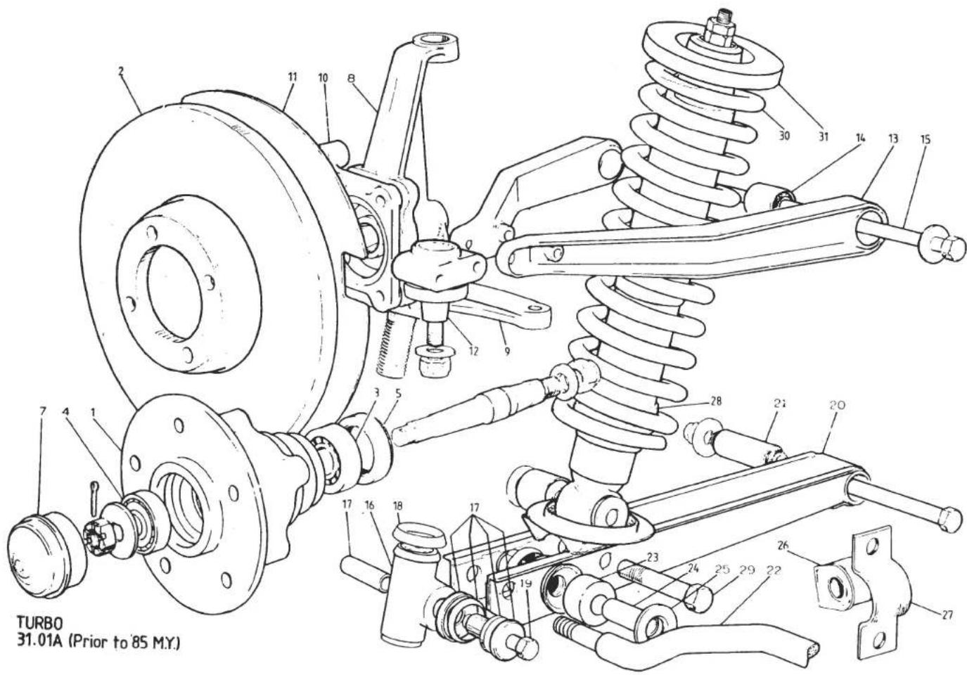


| ILLUS NO. | DESCRIPTION |  PART NUMBER PART NUMBER | QUANTITY | MAY 1091REMARKS | |
| ALL | |||||
| 31.01A | |||||
| 28 | Damper Assy. (includes A082C6033F)Damper Assy. (includes A082C6033F) | B082C4014FC082C4014F | 22 | This Page Prior to '85 Model YearFor '85 M.Y. Cars See 31.01B | |
| R/B C082C4014F In PairsGreen Spot on Lower BodyIf fitting to early car (up to approx. VIN 82D 1029, 82H 0334),with 16mm diameter damper stemhole in chassis: Fit only in pairswith 2 off Top Stem Bush Kit A082C6032F.Later cars have 19.5mm double thicknesshole and use Bush Kit A082C6033F. | |||||
| Bush Kit, Damper Top StemBush Kit, Damper Top StemBush, Damper Lower EyeWasher, Damper/Lower Link/NutBolt, 1⁄2" UNF x 21⁄2"Nut, Nyloc, 1⁄2" UNFRoad Spring, Red/GreenRoad Spring, Red/RedSpring Seat, Rubber | A082C6032FA082C6033FA075C6011FA075W4008FC075W2013FA075W3005FA082C4046FA082C4028FB075C0129Z | 2226222222 | With 16 mm Damper Stem Hole in ChassisWith 19.5mm Damper Stem Hole in ChassisIncluded in Damper assembly)Damper to Lower LinkHeater Cars OnlyAir Conditioned Cars OnlySpring to Chassis | ||
| d5p9 | Turbo (Prior '85 M.Y.) 31.01APage 4 | ||||
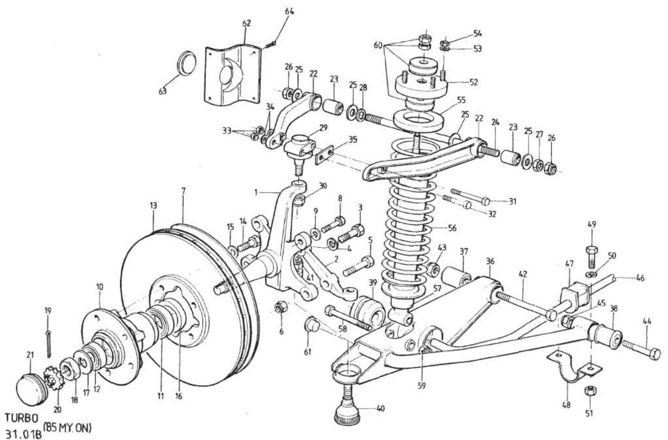
| ILLUS NO. | DESCRIPTION |  PART NUMBER PART NUMBER | QUANTITY | MAY REMARKS | |
| ALL | |||||
| 31.01B | |||||
| 1 | Vertical Link | C089C0163F | 2 | This Page '85 Model Year OnFor Cars Prior to '85 M.Y. See 31.01A | |
| 2 | Steering Arm RH | B082C4074F | 1 | ||
| Steering Arm LH | B082C4073F | 1 | |||
| 3 | Setscrew, M12 x 35, Arm/Link | A075W1059Z | 2 | ||
| 4 | Washer, Spring, Arm/Link | A075W4069F | 2 | ||
| 5 | Bolt, M12 x 45, Arm/Link | A075W1061Z | 2 | ||
| 6 | Nut, Nyloc, M12 Arm/Link | A075W3078F | 2 | ||
| 7 | Shield, Brake Disc, RH | C089C0750J | 1 | ||
| Shield, Brake Disc, LH | C089C0751J | 1 | |||
| 8 | Setscrew, Disc Shield/Vert. Link | A075W1039F | 2 | ||
| 9 | Washer, Flat, Shield/Vert. Link | A075W4021F | 2 | ||
| 10 | Hub, Front | B082C4078F | 2 | ||
| 11 | Bearing, Inboard, Front Hub | A089C8004F | 2 | ||
| 12 | Bearing, Outboard, Front Hub | A089C8005F | 2 | ||
| 13 | Brake Disc, Front Ventilated | A089J8014F | 2 | ||
| 14 | Bolt, Brake Disc to Hub | A089C8013F | 8 | ||
| 15 | Washer, Brake Disc to Hub | A089C8014F | 8 | ||
| 16 | Grease Seal, Front Hub | A089C8003F | 2 | A089D8003F May be used as Alternative | |
| 17 | Washer, Claw, Bearing Retaining | A089C8006F | 2 | ||
| 18 | Nut, Bearing Retaining | A089C8007F | 2 | ||
| 19 | Split Pin, Locking Cap | A075W6222Z | 2 | ||
| 20 | Locking Cap, Bearing Nut | A089C8009F | 2 | ||
| 21 | Grease Cap, Hub Bearing | A089C8008F | 2 | ||
| 22 | Arm, Upper Wishbone | E075C0130F | 4 | ||
| 23 | Pivot Bush, Upper Wishbone | X036C6004F | 4 | ||
| 24 | Stud, Upper Wishbone Pivot | A075C0145F | 2 | ||
| 25 | Buffer Washer, Pivot Bush | A075C0149D | 8 | ||
| 26 | Nut, Nyloc, ‡" UNF | A075W3005F | 4 | ||
| 27 | Locknut, ‡" UNF | A075W3017F | 2 | May be used in place of front nylocif castor shims are fitted | |
| d5p10 | Turbo ('85 M.Y. on) 31.01BPage 1 | ||||
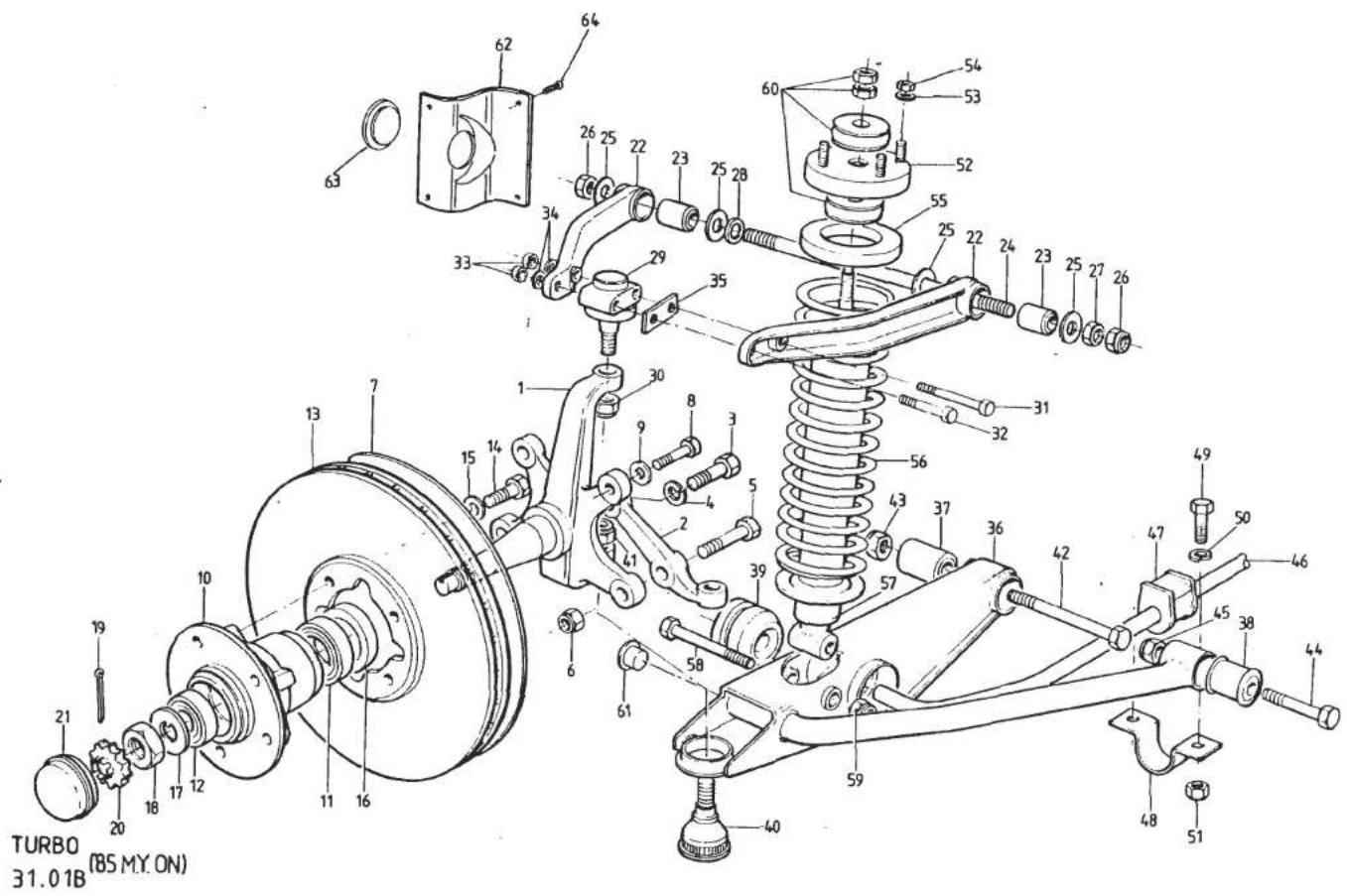
| ILLUS NO. | DESCRIPTION |  PART NUMBER PART NUMBER | QUANTITY | MAY 1991REMARKS | |
| ALL | |||||
| 31.01B | |||||
| 28 | Shim Washer, Castor Adjust, 1.5mm | A082C4091F | A/R | This Page'85 Model Year OnFor Cars Prior to '85 M.Y. See 31.01A)If Fitted)Upper Ball Joint to Vertical LinkMay be used if Castor Shims FittedIf FittedIf Fitted | |
| Shim Washer, Castor Adjust, 3.0mm | A082C4092F | A/R | |||
| Shim Washer, Castor Adjust, 6.0mm | A082C4093F | A/R | |||
| 29 | Ball Joint, Upper | A036C6007F | 2 | ||
| 30 | Nut, Torqloc, 7/16" UNF | A075W3004F | 2 | ||
| Washer, Flat, Ball Joint/Wishbone | A075W4005Z | 2 | |||
| 31 | Bolt, M8 x 100, Ball Joint/Wishbone | A075W2049Z | 2 | ||
| 32 | Bolt, M8 x 60, Ball Joint/Wishbone | A075W2043F | 2 | ||
| Bolt, M8 x 65, " " " " | A075W2044F | 2 | |||
| 33 | Nut, Nyloc, M8, " " " " | A075W3010F | 4 | ||
| 34 | Washer, Plain, " " " " | A075W4020F | 4 | ||
| 35 | Shimplate, Castor Adjust, 1.5mm | B082C4090F | A/R | ||
| Shimplate, Castor Adjust, 3.0mm | B082C4089F | A/R | |||
| 36 | Lower Wishbone, RH | B082C4076J | 1 | ||
| Lower Wishbone, LH | B082C4077J | 1 | |||
| 37 | Pivot Bush, Lower Wishbone, Rear | A075C6000F | 2 | ||
| 38 | Pivot Bush, Lower Wishbone, Front | A082D4084F | 2 | ||
| 39 | Bush, Anti-Roll Bar/Lower Wishbone | A089C6088F | 2 | ||
| 40 | Ball Joint, Lower | A089C6089F | 1 | ||
| 41 | Nut, Nyloc, M14 | A075W3069Z | 2 | Lower Ball Joint to Vertical LinkLower Link Rear to Chassis>Lower Link Front to Chassis>Turbo ('85 M.Y. on) 31.01BPage 2 | |
| 42 | Pivot Bolt, 1⁄2" UNF x 6" | A075W2015F | 2 | ||
| 43 | Nut, Nyloc, 1⁄2" UNF | A075W3005F | 2 | ||
| 44 | Pivot Bolt, 1⁄2" UNF x 2 3/4" | A075W2097F | 2 | ||
| 45 | Nut, Nyloc, 1⁄2" UNF | A075W3005F | 2 | ||
| 46 | Anti-Roll Bar | B082C4070F | 1 | ||
| 47 | Bush, Anti-Roll Bar to Chassis | A082C4084F | 2 | ||
| 48 | Clamp, Anti-Roll Bar to Chassis | A082C4047F | 2 | ||
| 49 | Setscrew, M12 x 35, ARB to Chassis | A079W1059F | 4 | ||
| 50 | Washer, Flat, " " " | A075W4028Z | 4 | ||
| d5pll | |||||
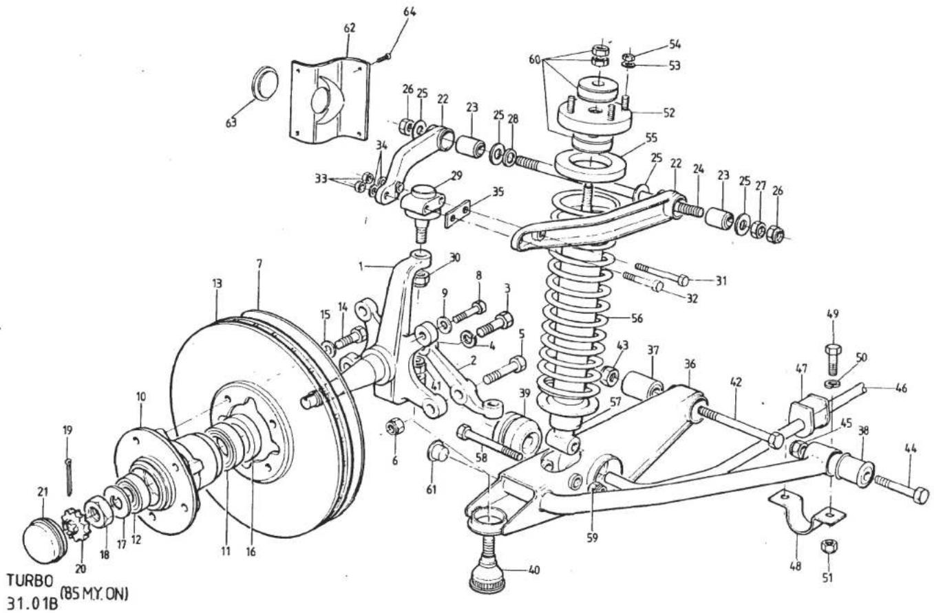
| ILLUS NO. | DESCRIPTION |  PART NUMBER PART NUMBER | QUANTITY | MAY 1991REMARKS | |
| ALL | |||||
| 31.01B | |||||
| 51 | Nut, Nyloc, M12, ARB to Chassis | A075W3012Z | 4 | This Page '85 Model Year On.For Cars Prior to '85 M.Y. See 31.01A | |
| 52 | Abutment Plate, Spring/Damper Top | A082C4075F | 2 | ||
| 53 | Washer, Abutment Plate/Chassis | A075W4020F | 8 | ||
| 54 | Nut, MB " " " " " | A075W3010F | 8 | ||
| 55 | Insulator, Front Spring Top | A082C4069F | 2 | ||
| 56 | Spring/Damper Assy. (Parallel Spring) | A082C4087J | 2 | Heater Only ) | |
| Spring/Damper Assy. (Parallel Spring) | A082C4094J | 2 | With A/C )Replaced by | ||
| Road Spring, Parallel, (Purple/Red) | A082C4083F | 2 | Heater Only )Conical Spring/Damper | ||
| Road Spring, Parallel, (Yellow/Yellow) | A082C4088F | 2 | With A/C )Assembly | ||
| 57 | Spring/Damper Assy. (Conical Spring) | A082C4098J | 2 | Heater Only. Includes Top Abutment Plate | |
| Spring/Damper Assy. (Conical Spring) | A082C4099J | 2 | With A/C. Includes Top Abutment Plate | ||
| Road Spring, Conical, (Purple/Blue) | A082C4096F | 2 | Heater Only | ||
| Road Spring, Conical, (Yellow/White) | A082C4097F | 2 | With A/C. R/B B082C4097F | ||
| Road Spring, Conical, (Yellow/Purple) | B082C4097F | 2 | With A/C (Longer than 'A') | ||
| Damper, Front, Black with White Spot | A082C4086F | 2 | For Parallel Spring (R/B ) Inc. Top A082C4095F + Conical Spring) ) Stem Bush | ||
| Damper, Front, Black with Red Spot | A082C4095F | 2 | For Conical Spring ) Kit. | ||
| 58 | Bolt, 1⁄2" UNF x 31⁄2" | A079W2088F | 2 | >Damper to Lower Wishbone | |
| 59 | Nut, Nyloc, 1⁄2" UNF | A075W3005F | 2 | > | |
| 60 | Bush Kit, Damper Top Stem | A082C6036F | 2 | ||
| 61 | Blanking Plug, Plastic | A089U6089F | 2 | ||
| 62 | Cover, Wishbone Stud Access | A082B4337K | 2 | R/B A079U4352K | |
| Cover, Wishbone Stud Access | A079U4352K | 2 | |||
| 63 | Grommet, Wishbone Stud Access | A082B6057F | 2 | ||
| 64 | Screw, Cover Fixing | A075W5022Z | 8 | ||
| d5p12 | Turbo ('85 M.Y. on) 31.01BPage 3 | ||||

| ILLUS NO. | DESCRIPTION |  PART NUMBER PART NUMBER | QUANTITY | MAY 1991REMARKS | |
| ALL | |||||
| 31.03A | |||||
| Rear Hub Assembly (with studs) | B082D4071F | 2 | Compomotive Wheels | ||
| Stud, Wheel | A079D6002H | 8 | Compomotive Wheels | ||
| 1 | Rear Hub | A082D4094F | 2 | BBS Wheels | |
| 2 | Nut, Hub Retaining | A082D4062F | 2 | ||
| 3 | Split Pin, Hub Nut | A075W6010Z | 2 | ||
| 4 | Cone, Hub Retention | A075D0256F | 2 | ||
| 5 | Bearing, Rear Wheel | A082D6012F | 2 | ||
| 6 | Circlip, Bearing Retaining | A082D6013F | 2 | ||
| 7 | Spacer, Drive Shaft/Bearing | A082D4064F | 2 | ||
| 8 | Drive Shaft, Outboard | A082D4067F | 2 | ||
| 9 | Drive Shaft Assembly, Intermediate | B082D4057F | 2 | ||
| Boot Kit, Drive Shaft C.V. Joint | A082D6018F | 4 | |||
| 10 | Bolt, Allen, M10 x 65 x 1.5 mm | A079W7020F | 24 | D.Shaft to Adaptor and Outboard D.Shaft | |
| 11 | Segment Washer | A082D6017F | 12 | ||
| 12 | Adaptor, Driveshaft | A082D4053F | 2 | ||
| Nut Special | B079D6011F | 6 | |||
| Washer, Spring, 12 mm | A075W4069F | 6 | |||
| Stud, Output Shaft/Adaptor | A079D6003F | 6 | |||
| 16 | Shim, Output Shaft to Disc | A079D4022K | 4 | ||
| 17 | Hub Carrier, RH | A082D4072K | 1 | ||
| Hub Carrier, LH | A082D4073K | 1 | |||
| 18 | Radius Arm, RH | B082D4056K | 1 | Compomotive Wheels | |
| Radius Arm, RH | B082D4078K | 1 | BBS Wheels.R/B C082D4078K With 130mm Bolts | ||
| Radius Arm, RH | C082D4078K | 1 | BBS Wheels.R/B B082D4110J | ||
| Radius Arm, RH | B082D4110J | 1 | |||
| Radius Arm, LH | B082D4055K | 1 | Compomotive Wheels | ||
| Radius Arm, LH | B082D4077K | 1 | BBS Wheels.R/B C082D4077K With 130mm Bolts | ||
| Radius Arm, LH | C082D4077K | 1 | BBS Wheels.R/B B082D411LJ | ||
| Radius Arm, LH | B082D411LJ | 1 | |||
| 19 | Bolt, M10 x 120, Rad. Arm/Hub Carrier | A075W2064Z | 4 | Except Rad. Arm C082D4077/8 | |
| Bolt, M10 x 130, Rad. Arm/Hub Carrier | A075W2065F | 4 | For Rad. Arm C082D4077/8 | ||
| 20 | Nut, Nyloc M10 | A075W3011F | 4 | ) | |
| Washer, Plain | A075W4024Z | 4 | )Radius Arm to Hub CarrierTurbo 31.03APage 1 | ||
| d5p13 | |||||
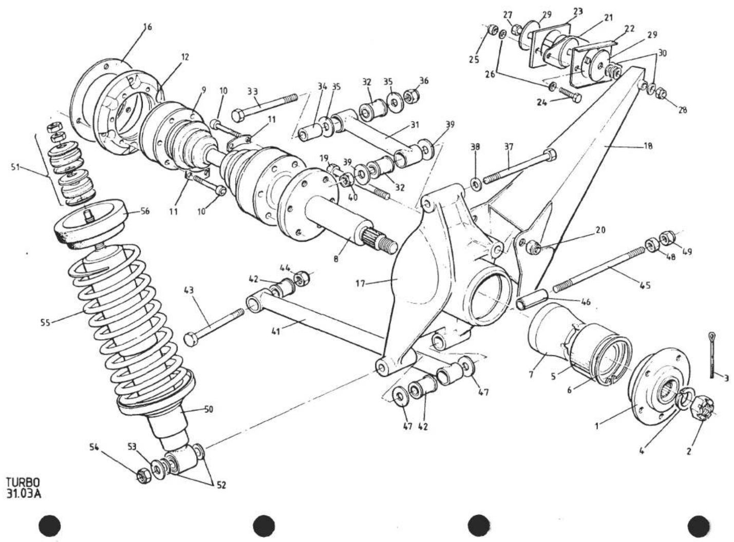
| ILLUSNO. | DESCRIPTION |  PART NUMBER PART NUMBER | QUANTITY | REMARKS | |
| ALL | |||||
| 31.03A | |||||
| 21 | Mounting Rubber | A046D6000F | 2 | Radius Arm to Chassis | |
| 22 | Plate, Reinforcing | C079D4013K | 2 | > | |
| 23 | Spacer, 0.9mm, Toe-In Adjust | C079D4051F | A/R | > | |
| Spacer, 1.5mm, Toe-In Adjust | A079D4051F | A/R | > | ||
| Spacer, 6.0mm, Toe-in Adjust | B079D4051F | A/R | >Radius Arm Mounting to Chassis | ||
| 24 | Setscrew, M8 x 35 | A075W1041F | 4 | > | |
| 25 | Nut, Nyloc M8 | 4 | > | ||
| 26 | Washer, Plain | A075W4020Z | 8 | > | |
| 27 | Bolt, 7/16" x 4.1/2", UNF | A075W2087F | 2 | ) | |
| 28 | Nut, Torqloc, 7/16" UNF | A075W3004F | 2 | ) | |
| 29 | Washer, Large, 7/16" x 1 1/2 " | A075W4006F | 4 | )Radius Arm to Mounting | |
| 30 | Washer, Toe-In Adjust | A075W4005F | 10 | ) | |
| Upper Link (Less Bushes) | A082D4086F | 2 | > | ||
| Bush, Upper Link (Metalastick) | A082D6016F | 4 | > | ||
| Bolt, 1/2 " UNF x 5", Link/Chassis | A079W2025F | 2 | >Compomotive Wheels | ||
| Spacer, Split | A079D4025F | 2 | > | ||
| Washer, 1/2 " x 1. 1/4" | A075W4008Z | 2 | > | ||
| Nut, Nyloc, 1/2 " UNF | A075W3005F | 2 | > | ||
| 31 | Upper Link (Less Bushes) | B082D4081F | 2 | )BBS Wheels | |
| 32 | Bush, Upper Link (Silentbloc) | A082D4084F | 4 | ) | |
| Bolt, 1/2 " UNF x 5", Link/Chassis | A079W2025F | 2 | > | ||
| Spacer, Split | A079D4025F | 2 | >BBS Wheels up to VIN 82 D 1161 | ||
| Washer, 1/2 " x 1 3/4" | A079W4083F | 4 | > 82 - 0346 | ||
| Nut, Nyloc, 1/2 " UNF | A075W3005F | 2 | > | ||
| 33 | Bolt, 1/2 " UNF x 4 1/2 ", Link/Chassis | A079W2023F | 2 | ) | |
| 34 | Spacer | A082D4099K | 2 | )BBS Wheels From VIN 82 D 1162 | |
| 35 | Washer, 1/2 " x 1 3/4" | A079W4083F | 4 | ) 82 - 0347 | |
| 36 | Nut, Nyloc, 1/2 " UNF | A075W3005F | 2 | ) | |
| d5pl4 | Turbo 31.03APage 2 | ||||

| ILLUSNO. | DESCRIPTION | PART NUMBER | QUANTITY | MAY 1991REMARKS | |
| ALL | |||||
| 31.03A | |||||
| 37 | Bolt, 1⁄2" UNF x 5.1/2" Top Link/Carrier | A079W2091F | 2 | ) | |
| Washer, Bolt/Carrier, Nut/Link | A075W4008Z | 4 | ) Compomotive Wheels | ||
| Washer, 1⁄2" Hardened, Link/Carrier | A074D6003F | 2 | ) | ||
| Nut, Nyloc, 1⁄2" UNF | A075W3005F | 2 | ) | ||
| Bolt, 1⁄2" UNF x 5.1/2" Top Link/Carrier | A079W2091F | 2 | > | ||
| 38 | Washer, Bolt Head | A074D6003Z | 2 | > BBS Wheels | |
| 39 | Washer, 1⁄2" x 1.3/4" | A079W4083F | 4 | > | |
| 40 | Nut, Nyloc 1⁄2" UNF | A075W3005F | 2 | > | |
| Lower Link, (Less Bushes) | A082D4060F | 2 | ) | ||
| Bush, Lower Link, Outer, Metalastik | A082D6016F | 2 | ) Compomotive Wheels | ||
| Bush, Lower Link, Inner, Metalastik | A074D6002F | 2 | ) | ||
| 41 | Lower Link (Less Bushes) | B082D4083F | 2 | > BBS Wheels | |
| 42 | Bush, Lower Link, Silentbloc | A082D4084F | 4 | > | |
| 43 | Bolt, 1⁄2" UNF x 2.1/2", Link/Chassis | A075W2097F | 2 | ||
| 44 | Nut, Nyloc, 1⁄2" UNF, Link/Chassis | A075W3005F | 2 | ||
| 45 | Stud, Lower Link/Hub Carrier | B079D4024F | 2 | ||
| 46 | Split Spacer | B082D4079F | 2 | ||
| Washer, 1⁄2" x 1.1/4", Link/Spacer | A075W4008Z | 2 | ) | ||
| Washer, 1⁄2" Hardened, Link/Carrier | A074D6003F | 2 | )Compomotive Wheels | ||
| 47 | Washer, 1⁄2" x 1.3/4" | A079W4083F | 4 | BBS Wheels | |
| 48 | Locknut, 1⁄2" UNF | A075W3017F | 2 | ||
| 49 | Nut, Nyloc, 1⁄2" UNF | A075W3005F | 2 | ||
| 50 | Damper Assy. (Includes A082C6033F) | B082D4058F | 2 | Prior to '85 M.Y. R/B C082D4058F | |
| Damper Assy. (Includes A082C6033F) | C082D4058F | 2 | Prior to '85 Model Year | ||
| Blue With Green Spot on Lower Body | |||||
| If fitting to early car (up to approx. | |||||
| VIN 82D 1029, 82H 0334), with 16mm | |||||
| diameter damper stem hole in chassis: | |||||
| Fit only in pairs with 2 off top stem | |||||
| bush kit A082C6032F. | |||||
| Later cars have 19.5mm double thickness | |||||
| hole and use bush kit A082C6033F. | |||||
| d5p15 | Turbo 31.03APage 3 | ||||

| ILLUS NO. | DESCRIPTION |  | QUANTITY |  | |
| PART NUMBER | ALL |  | |||
| 31.03A | |||||
| 51 | Damper Assy. (Includes A082C6036F) | A082D4102F | 2 | 1985 Model Year OnwardBlack With White Spot on Lower Body16mm Chassis Hole ) Prior to19.5mm Chassis Hole ) '85 M.Y.1985 Model Year On. | |
| Bush Kit, Damper Top Stem (3/8" UNF) | A082C6032F | 2 | |||
| Bush Kit, Damper Top Stem (3/8" UNF) | A082C6033F | 2 | |||
| Bush Kit, Damper Top Stem (M10) | A082C6036F | 2 | |||
| 52 | Spacer Washer, Damper Lower Fix | A075W4028F | 4 | ||
| 53 | Washer, Flat | A075W4008F | 2 | ||
| 54 | Nut, Nyloc, 1⁄2" UNF, Damper/Carrier | A075W3005F | 2 | ||
| 55 | Road Spring, Green/Green | E079D4003F | 2 | Heater only carsA/C cars. R/B D079D4003F in pairsA/C cars. 1⁄2" longer than E079D4003F | |
| Road Spring, Green/Green | E079D4003F | 2 | |||
| Road Spring, Green | D079D4003F | 2 | |||
| 56 | Insulator, Rear Spring | A079D4028F | 2 | ||
| Grommet, RH Wheelarch | A082U6073F | 1 | |||
| d5p16 | Turbo 31.03APage 4 | ||||
TURBO 32.01A

LHD ILLUSTRATED


| ILLUSNO. | DESCRIPTION |  PART NUMBER PART NUMBER | QUANTITY | MAY 1991REMARKS | |
| RHD | LHD | ||||
| 32.01A | |||||
| 001 | Protective Sleeve, Column Spline | A079H4010K | 1 | 1 | |
| 002 | Intermediate Steering Column Assy. | A079H4002F | 1 | 1 | Inc. Upper U/J |
| 003 | Universal Joint, Lower | C075H6009F | 1 | 1 | |
| 004 | Bolt, M8 x 35, Universal Joint Clamping | A079H4019F | 3 | 3 | |
| 005 | Washer, Flat, U/J Clamp Bolt | A075W4020Z | 3 | 3 | |
| 006 | Nut, Nyloc, M8 U/J Clamp Bolt | A075W3010Z | 3 | 3 | |
| Protective Sleeve, Pinion Shaft | A079H4011K | 1 | 1 | R/B A082H4030H plus A082H6025F | |
| 007 | Spacer, Column Lower U/J | A082H4030H | 1 | 1 | |
| 008 | Circlip, Pinion Shaft/Spacer | A082H6025F | 1 | 1 | |
| 009 | Rack & Pinion Assembly | A082H4021F | 1 | R/B D082H4021F With Reduced Travel | |
| Rack & Pinion Assembly | D082H4021F | 1 | |||
| Rack & Pinion Assembly | A082H4020F | 1 | R/B D082H4020F with Reduced Travel | ||
| Rack & Pinion Assembly | D082H4020F | 1 | |||
| 010 | Ball Joint Track Rod End | A075H6001Z | 2 | 2 | |
| 011 | Locknut, 1⁄2" UNF, Ball Joint | A075W3017Z | 2 | 2 | |
| 012 | Tapping Plate, Steering Rack Mounting | B079H4004F | 2 | 2 | |
| Shim, Rack Assy. to Chassis | A079H4006K | 4 | 4 | ||
| 014 | Clamp Bracket, Rack Assy. to Chassis | B007H4104Z | 1 | 1 | Non-Pinion End |
| 015 | Clamp Bracket, Rack Assy. to Chassis | B007H4105Z | 1 | 1 | Pinion End |
| 016 | Rubber Mounting, Rack Assembly | A007H4103Z | 1 | 1 | Non-Pinion End |
| 017 | Rubber Mounting, Rack Assembly | A007H4106Z | 1 | 1 | Pinion End |
| 018 | Setscrew, M8 x 20, Clamp to Chassis | A075W1038Z | 4 | 4 | |
| 019 | Washer, Spring, Clamp to Chassis | A075W4036Z | 4 | 4 | |
| 020 | Gaiter Set, Steering Rack (inc. clips) | A082H6023F | 1 | 1 | |

| ILLUSNO. | DESCRIPTION |  PART NUMBER PART NUMBER | QUANTITY | MAY 1991REMARKS | |
| RHD | LHD | ||||
| 32.05A | |||||
| 001 | Nut, Steering Wheel to Column | A075W3005Z | 1 | 1 | |
| 002 | Washer, Steering Wheel Nut | A075W4008Z | 1 | 1 | |
| 003 | Collet, Steering Wheel Thrust | A085H6018F | 2 | 2 | |
| 004 | Band, Collet Retaining | A085H6019F | 1 | 1 | |
| Steering Wheel Assembly, Black | A085H4028F | 1 | 1 | With 'Old' Badge ) | |
| Steering Wheel Assembly, Black | C085H4028F | 1 | 1 | With 'New' Badge )inc. * Items | |
| *006 | Steering Wheel, Black Leather | A079H6009H | 1 | 1 | |
| Steering Wheel, Coloured Leather | B079H6009H | 1 | 1 | Special Order. State VIN or Colour | |
| *007 | Hub, Steering Wheel | A085H4026H | 1 | 1 | |
| *008 | Roll Pin, Turn Indicator Cancelling | A079H6013H | 2 | 2 | |
| *009 | Fixing, Wheel to Hub | A079H6012H | 6 | 6 | |
| *010 | Wheel Centre ('Old' Badge) | A082H6016H | 1 | 1 | |
| Wheel Centre ('New' Badge) | B082H6024H | 1 | 1 | ||
| 011 | Crash Pad, Black Leather | A082V4789K | 1 | 1 | |
| Crash Pad, Coloured Leather | B082V4789K | 1 | 1 | Special Order. State VIN or Colour | |
| 015 | Steering Column Assembly | B079H6006F | 1 | 1 | |
| 016 | Setscrew, M10 x 25, Column/Scuttle | A075W1048Z | 2 | 2 | |
| 017 | Washer, Flat, Column/Scuttle | A075W4025Z | 2 | 2 | |
| 018 | Washer, Shakeproof, Column/Scuttle | A075W4044Z | 2 | 2 | |
| 019 | Nut, Special, Column/Scuttle | A079U4098F | 2 | 2 | |
| 022 | Clamp, Column to Pedal Box | A082H4022J | 1 | ||
| Clamp, Column to Pedal Box | A082H4023J | 1 | |||
| 025 | Nut, Nyloc M8, Clamp to Pedal Box | A075W3010Z | 2 | 2 | |
| 026 | Washer, Flat, Clamp to Pedal Box | A075W4020Z | 2 | 2 | |
| 027 | Lock, Steering Column c/w Ignition Switch | A079H6001F | 1 | 1 | |
| 028 | Shear Bolt, Lock to Column | A079H6008F | 2 | 2 | |
| 037 | Seal Plate, Column to Bulkhead | A079U4332F | 1 | ||
| Seal Plate, Column to Bulkhead | A079U4331F | 1 | |||
| 040 | Gasket, Seal Plate to Bulkhead | B079U4325F | 1 | 1 | |
| 041 | Setscrew, M6 x 20, Plate to B/Head | A075W1030Z | 1 | 1 | |
| 042 | Washer, Sealplate Fix | A075W4015Z | 1 | 1 | |
| 043 | Nut, Nyloc, M6 | A075W3009F | 1 | 1 | |
| Turbo 32.05A | |||||
| d5p18 | |||||
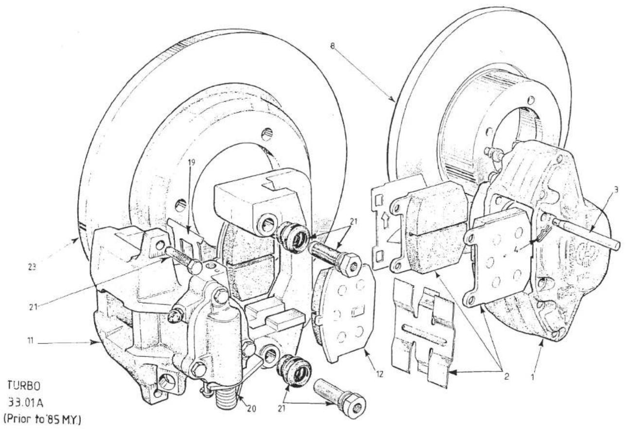
| ILLUSNO. | DESCRIPTION | PART NUMBER | QUANTITY | MAY 1991REMARKS | |
| ALL | |||||
| 33.01A | This Page prior to '85 M.Y.For '85 M.Y. See 33.01B | ||||
| 1 | Caliper Assembly, Front, RH | B082J6052F | 1 | Includes Brake Pads | |
| Caliper Assembly, Front, LH | B082J6053F | 1 | Includes Brake Pads | ||
| 2 | Brake Pad Set, Front | A082J6058F | 1 | Includes Pins & Clips | |
| 3 | Pin, Pad Retaining | A079J6026F | 4 | ||
| 4 | Clip, Pin Retaining | A079J6027F | 4 | ||
| Bolt, Caliper to Mounting Bracket | A079J6007F | 4 | |||
| Washer, Spring, 12 mm | A075W4069F | 4 | |||
| Service Kit, Front Caliper | X036J6003ZJ | A/R | Includes 4 Piston Seals, 4 Dust Boots,4 Dust Boot Clips | ||
| 8 | Disc, Front Brake | A075J0297Z | 2 | ||
| Bolt, Disc to Hub | A075W1024F | 8 | |||
| Washer, Spring, 3/8" | A075W4067F | 8 | |||
| 11 | Caliper Assembly, Rear, RH | A079J6012F | 1 | ||
| Caliper Assembly, Rear, LH | A079J6004F | 1 | |||
| 12 | Brake Pad Set, Rear | A079J6024F | 1 | Includes Locking Bolts | |
| Bolt, M10 x 100, Caliper Mounting | A079W2062F | 2 | |||
| Bolt, M10 x 60, Caliper Mounting | A079W2055Z | 2 | |||
| Washer, Spring, 10 mm | A079W4070Z | 4 | |||
| Washer, Plain, 10 mm | A075W4024Z | 4 | |||
| Ring Dowel, Caliper | A079J6018F | 4 | |||
| Adaptor, Caliper to Brake Hose | A079J6051F | 2 | |||
| 19 | Pad Damping Spring | A079J6047F | 4 | ||
| 20 | Return Spring, RH | A079J6049F | 1 | Handbrake Lever Arm | |
| Return Spring, LH | A079J6048F | 1 | Handbrake Lever Arm | ||
| Seal Kit, Rear Caliper | A079J6042F | A/R | |||
| 21 | Guide Pin Kit | A079J6045F | A/R | Includes 4 Guide Pins, 4 Locking Bolts,4 Bolts and Grease)inc. H/Brake Mechanism)Turbo (Prior to '85 M.Y.) 33.01APage 1 | |
| Piston Kit, Rear Caliper, LH | A079J6043F | A/R | |||
| Piston Kit, Rear Caliper, RH | A079J6044F | A/R | |||
| Bleed Screw, Rear Caliper | A079J6046F | 2 | |||
| d5p19 | |||||

| ILLUS NO. | DESCRIPTION |  | QUANTITY | MAY 1991 | |
| 33.01A | PART NUMBER | ALL | REMARKS | ||
| 23 | Disc, Rear Brake Nut, M12, Disc Fixing Washer, Spring, Disc Fixing | A079J4000F A079D6011F A075W4069F | 2 6 6 | This Page Prior to '85 M.Y For '85 M.Y. See 33.01B | |
| d5p20 | Turbo (Prior to '85 M.Y.) 33.01A Page 2 | ||||
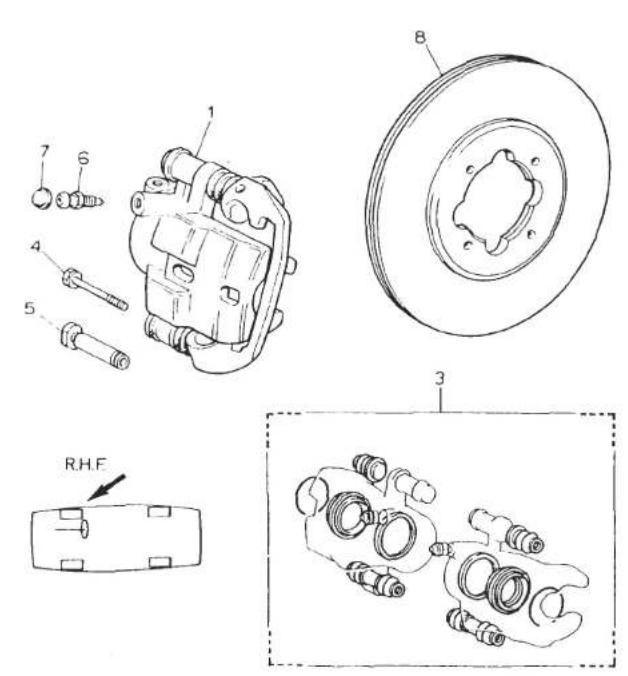

33.01B
TURBO (85 M.Y. ON)
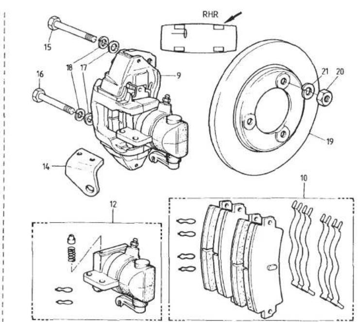
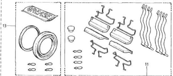
J53


| ILLUS NO. | DESCRIPTION |  PART NUMBER PART NUMBER | QUANTITY | MAY ISSI REMARKS | |
| ALL | |||||
| 33.01B | |||||
| 1 | Brake Caliper Assembly, RH Front | A089J8056F | 1 | This Page '85 M.Y. Onward For Cars Prior to '85 M.Y. See 33.01A | |
| Brake Caliper Assembly, LH Front | A089J8057F | 1 | |||
| 2 | Pad Set, Including Anti-Rattle Springs | A089J8055F | 1 | ||
| 3 | Caliper Repair Kit, Front | A089J8025F | 1 | ||
| 4 | Bolt, Caliper Swing Release | A089J8068F | 2 | ||
| 5 | Bush, Lower, Caliper Sliding | A089J8069F | 2 | ||
| 6 | Bleed Nipple, Front Caliper | A089J8026F | 2 | ||
| 7 | Dust Cap, Bleed Nipple | A089J8013F | 2 | ||
| Bolt, Caliper Fixing | A089J0358F | 4 | |||
| Washer, Shakeproof, Caliper Fix | A075W4069F | 4 | |||
| 8 | Brake Disc, Front, Ventilated | A089J8014F | 2 | ||
| Bolt, Brake Disc to Hub | A089C8013F | 8 | |||
| Washer, Brake Disc to Bolt | A089C8014F | 8 | |||
| 9 | Brake Caliper Assembly, RH Rear | A082J4132F | 1 | Includes Brake Pads | |
| Brake Caliper Assembly, LH Rear | A082J4131F | 1 | Includes Brake Pads | ||
| 10 | Pad Set, Rear Calipers | A082J6076F | 1 | Inc. Anti-Rattle Springs & Locking Clips | |
| 11 | Accessory Kit, Rear Calipers | A082J6078F | 1 | Inc. Anti-Rattle Springs, Locking Clips Retaining Plates, Springs, Bleed Caps)Inc. Locking Pin & Spring) | |
| 12 | Cylinder Assembly, RH | A082J6080F | 1 | ||
| Cylinder Assembly, LH | A082J6081F | 1 | |||
| 13 | Seal Kit, Rear Caliper | A082J6079F | 2 | Inc. Piston Seal, Piston Boot, Locking Clips & Grease | |
| 14 | Abutment, Park Braking Cable, RH | B082J4128F | 1 | ||
| Abutment, Parking Brake Cable, LH | B082J4127F | 1 | |||
| Setscrew, M8 x 20, Abutment/Caliper | A075W1038Z | 4 | |||
| Spring Washer, Abutment/Caliper | A075W4036Z | 4 | |||
| 15 | Bolt, M12 x 85, Caliper Fix, Top | A082J4144F | 2 | ||
| 16 | Bolt, M12 x 75, Caliper Fix, Bottom | A082J4145F | 2 | Turbo ('85 M.Y. On) 33.01B | |
| 17 | Washer, Flat, Caliper Fix | A075W4028Z | 4 | Page 1 | |
| d5p21 | |||||
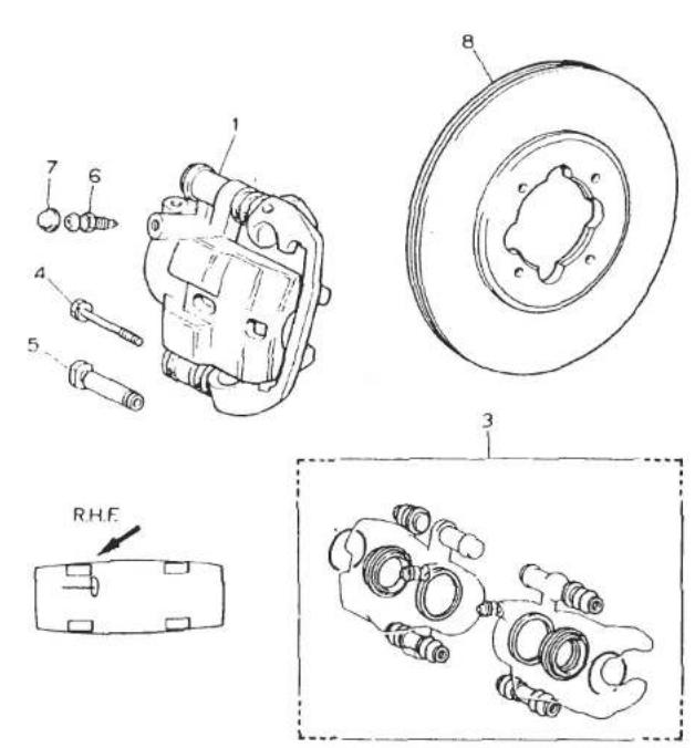

33.01B
TURBO (85 M.Y. ON)


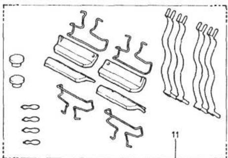

J53

A
| ILLUSNO. | DESCRIPTION |  PART NUMBER PART NUMBER | QUANTITY | MAY 1991REMARKS | |
| ALL | |||||
| 33.01B | |||||
| 18 | Washer, Spring, Caliper Fix | A075W4069F | 4 | This Page '85 M.Y. OnwardFor Cars Prior to '85 M.Y. See 33.01A | |
| 19 | Brake Disc, Rear | A082J4124F | 2 | ||
| 20 | Nut, M12, Disc Fixing | A079D6011F | 6 | White Colour Code or Cast Part Number | |
| 21 | Washer, Spring, Disc Fixing | A075W4069F | 6 | ||
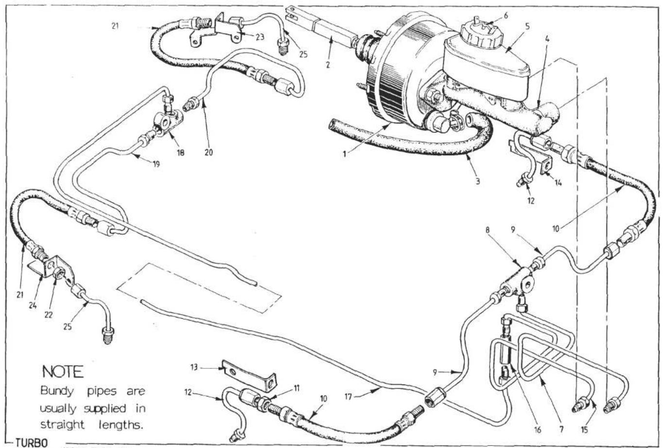
33.03A
(PRIOR TO '85 MY)
| ILLUS NO. | DESCRIPTION |  PART NUMBER PART NUMBER | QUANTITY | MAY 1991REMARKS | |
| LHD | RHD | ||||
| 33.03A | This Page Prior to '85 M.Y.For Cars '85 M.Y. On See 33.03B | ||||
| 1 | Servo Assembly, Girling Type 50 | A075J6080F | 1 | 1 | |
| 2 | Push Rod, Brake Pedal to Servo | B079J4037F | 1 | 1 | |
| Clevis Pin, Pushrod to Pedal | A079W6143F | 1 | 1 | R/B A082J4197F | |
| Clevis Pin, Pushrod to Pedal | A082J4197F | 1 | 1 | ||
| Spring Clip, Clevis Retaining | A075W6175F | 1 | 1 | ||
| Service Kit, Brake Servo | A075J6033F | 1 | 1 | ||
| Non-Return Valve Kit | A075J6081F | 1 | 1 | ||
| Bracket, Servo to Pedal Box | A079J4036J | 1 | 1 | R/B B079J4036J | |
| Bracket, Servo to Pedal Box | B079J4036J | 1 | 1 | ||
| Spacer, Bracket to Pedal Box | A079J4004K | 4 | 4 | ||
| Nut, Bracket to Pedal Box | A075W3010F | 2 | 2 | ||
| Nut, Servo to Mounting Bracket | A075W3010F | 4 | 4 | ||
| 3 | Hose, Vacuum, Servo to Bundy | BX75J0309K | 1 | 1 | |
| Grommet, Servo Hose | X036M6289Z | 1 | 1 | ||
| Bundy Pipe, Servo Vacuum | A082J4091F | 1 | 1 | ||
| Hose, Vacuum, Bundy to Manifold | A075J6078V | lm | lm | ||
| Clip, Vacuum Hose | A079M6132F | 4 | 4 | ||
| 4 | Brake Master Cylinder Assy. | A082J6064F | 1 | 1 | Type AS/AS |
| Nut, M10, M/Cylinder to Servo | A082J6068J | 2 | 2 | ||
| Washer, M/Cylinder to Servo | A082J6069J | 2 | 2 | ||
| 5 | Reservoir Kit, Master Cylinder | A082J6066F | 1 | 1 | |
| 6 | Fluid Level Warning Indicator | A079J6035F | 1 | 1 | |
| Service Kit, Master Cylinder | A082J6065F | 1 | 1 | ||
| Banjo, Master Cylinder to Front Pipe | A082J6061F | 1 | Where Fitted | ||
| Gasket, Banjo | A082J6063F | 1 | |||
| Gasket, Banjo | A082J6067F | 1 | |||
| Bolt, Banjo | A082J6062F | 1 | |||
| Grommet, Pipes Thro' Bulkhead | A075L6025F | 2 | 2 | ||
| 7 | Pipe, Front Brake, M/C to 3-Way | A082J4082F | 1 | ||
| Pipe, Front Brake, M/C to 3-Way | A082J4083F | 1 | Turbo (Prior to '85 M.Y.) 33.03APage 1 | ||
| d5p23 | |||||
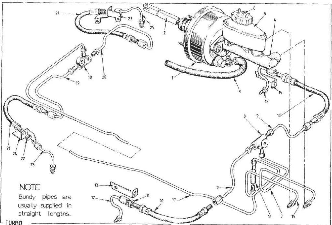
33.03A
(PRIOR TO '85 MYI)
| ILLUS NO. | DESCRIPTION |  PART NUMBER PART NUMBER | QUANTITY | MAY 1991REMARKS | |
| RHD | LHD | ||||
| 33.03A | This Page Prior to '85 M.Y.For Cars '85 M.Y. On See 33.03B | ||||
| 8 | Union 3-Way, Front | B075J6019Z | 1 | 1 | |
| 9 | Pipe, Brake, 3-Way to Hose | A079J4068F | 2 | 2 | |
| Clip, Brake Pipe | A075W6051Z | 5 | 5 | ||
| Screw, Pipe Clip to Chassis | A075W5011Z | 5 | 5 | ||
| 10 | Hose, Front Brake | C075J6015F | 2 | 2 | |
| 11 | Locknut, Front Brake Hose | A075J6017F | 4 | 4 | |
| Washer Shakeproof, Front Brake Hose | A075W4049Z | 4 | 4 | ||
| 12 | Pipe, Brake, Hose to Front Caliper | A079J4071F | 2 | 2 | |
| 13 | Bracket, Caliper Pipe Support, RH | A082J4080K | 1 | 1 | |
| 14 | Bracket, Pipe/Hose Support LH | A082J4081K | 1 | 1 | |
| 15 | Pipe, Brake, Rear Feed | A079J4066F | 1 | Master Cylinder to Double Ended Union | |
| Pipe, Brake, Rear Feed | A079J4072F | 1 | Master Cylinder to Double Ended Union | ||
| 16 | Union, Double Ended | A079J6020F | 1 | 1 | |
| 17 | Pipe, Double Ended Union to Rear 3-Way | A082J4099F | 1 | 1 | |
| 18 | Union, 3-Way, Rear | B075J6019Z | 1 | 1 | |
| 19 | Pipe, Brake, 3-Way to RH Hose | A082J4100F | 1 | 1 | |
| 20 | Pipe, Brake, 3-Way to LH Hose | C082J4101F | 1 | 1 | 850 mm |
| Pipe, Brake, 3-Way to LH Hose | A082J4150F | 1 | 1 | 790 mm | |
| Clip, Brake Pipe | A075W6051Z | 3 | 3 | ||
| Screw, Clip to Chassis | A075W5011Z | 3 | 3 | ||
| 21 | Hose, Rear Brake | B082J6060F | 2 | 2 | Replaced by C082J6060F |
| Hose, Rear Brake Armoured | C082J6060F | 2 | 2 | ||
| 22 | Locknut, Rear Brake Hose | A075J6017F | 4 | 4 | |
| Washer, Shakeproof, 10 mm | A075W4049Z | 2 | 2 | ||
| 23 | Bracket, Hose/Pipe to Caliper LH | A082J4095K | 1 | 1 | |
| 24 | Bracket, Hose/Pipe to Caliper RH | A082J4096K | 1 | 1 | |
| 25 | Pipe, Brake, Hose to Rear Caliper | A079J4071F | 2 | 2 | |
| Turbo (Prior '85 M.Y.) 33.03APage 2 | |||||
| d5p24 | |||||
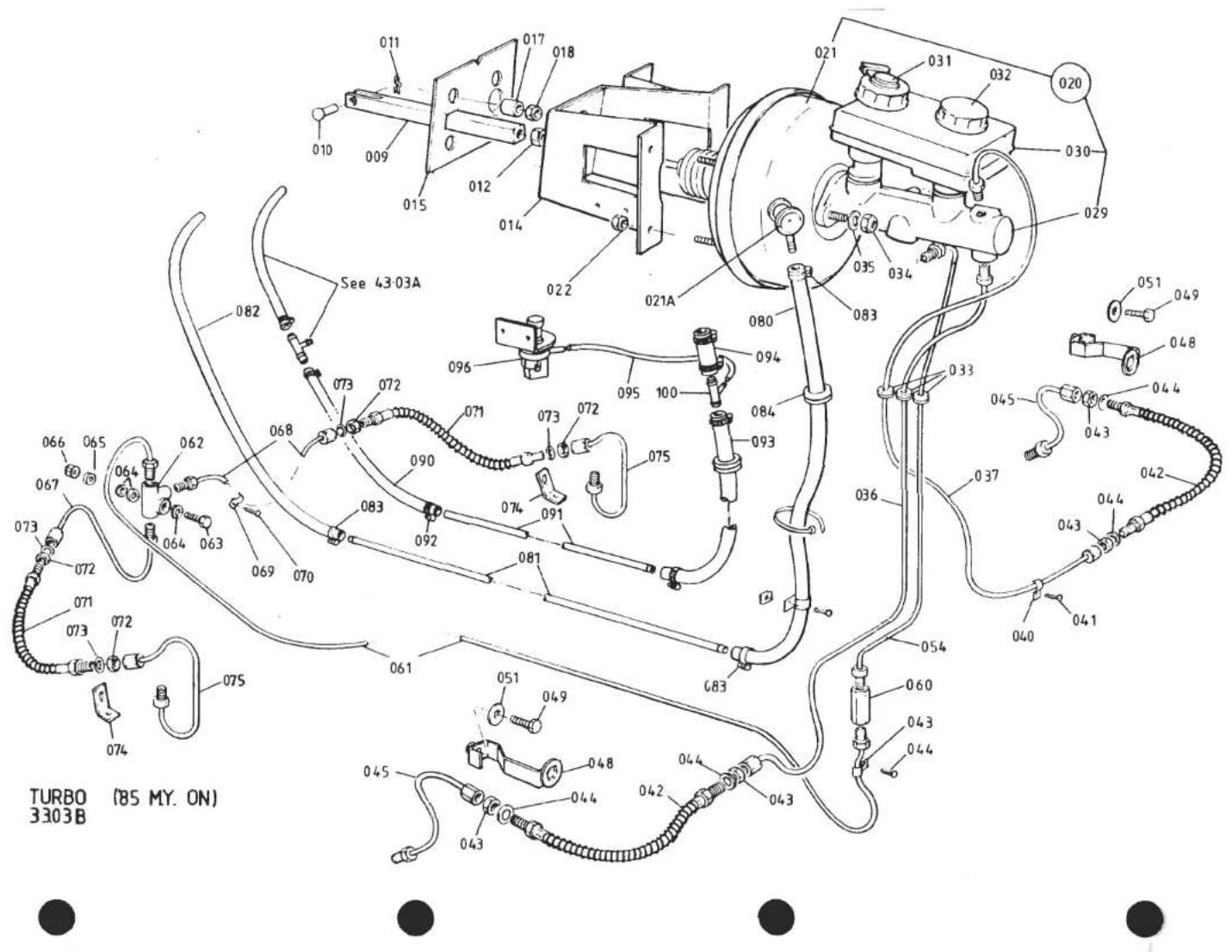
| ILLUSNO. | DESCRIPTION | PART NUMBER | QUANTITY | MAY 1991REMARKS | |
| RHD | LHD | ||||
| 33.03B | |||||
| 009 | Pushrod, Brake Pedal to Servo | A082J4139F | 1 | 1 | This page for '85 M.Y. onFor cars prior 1985 see 33.03A |
| 010 | Clevis Pin, Pedal to Pushrod | A082J4197F | 1 | 1 | |
| 011 | Spring Clip, Clevis Retaining | A075W6175F | 1 | 1 | |
| 012 | Locknut, Servo Pushrod | A075W3024Z | 1 | 1 | |
| 014 | Bracket, Servo & Clutch M/Cylinder Mtg. | A082J4143J | 1 | 1 | |
| 015 | Gasket, Servo Bracket to Body | A082J4156F | 1 | 1 | |
| 017 | Spacer, Bracket to Pedal Box | A079J4004K | 4 | 4 | |
| 018 | Nut, Nyloc, M8, Brkt. to Pedal Box | A075W3010Z | 4 | 4 | |
| Washer, Spring, Brkt. to Pedal Box | A075W4036Z | 4 | 4 | ||
| 020 | Servo/Brake Master Cylinder Assy. | A082J4147F | 1 | 1 | Inc. Reservoir Low Fluid Switch & Cap Inc. N.R.V. |
| 021 | Servo Assembly, (Bendix DBA) | A082J4134H | 1 | 1 | |
| 021A | Non Return Valve & Seal | A082J6084F | 1 | 1 | |
| 022 | Nut, Nyloc, M7, Servo to Bracket | A079F6023F | 4 | 4 | |
| Washer, Spring, Servo to Bracket | A075W4036Z | 4 | 4 | ||
| 029 | Brake Master Cylinder Assy. | A082J4133H | 1 | 1 | |
| 030 | Reservoir, Brake Master Cylinder | A082J4135H | 1 | 1 | |
| 031 | Fluid Level Warning Switch (Nivocode) | A082J4136H | 1 | 1 | |
| 032 | Cap, Filler, Fluid Reservoir | A082J4137H | 1 | 1 | |
| Repair Kit, Master Cylinder | A082J6082F | 1 | 1 | ||
| 033 | Grommet Pipes Through Body | A075L6025F | 3 | 3 | |
| 034 | Nut, Nyloc, MB, M/Cylinder to Servo | A075W3010Z | 2 | 2 | |
| 035 | Washer, Flat, M/Cylinder to Servo | A075W4020Z | 2 | 2 | |
| 036 | Pipe, Brake, M/Cylinder to RHF Hose | A082J4154F | 1 | ||
| Pipe, Brake, M/Cylinder to RHF Hose | A082J4152F | 1 | |||
| 037 | Pipe, Brake, M/Cylinder to LHF Hose | A082J4155F | 1 | ||
| Pipe, Brake, M/Cylinder to LHF Hose | A082J4151F | 1 | |||
| 040 | Clip, Brake Pipe to Chassis | A075W6051Z | 5 | 5 | |
| 041 | Screw, Pipe Clip to Chassis | A075W5011Z | 5 | 5 | |
| 042 | Hose, Front Brake | B089J6012F | 2 | 2 | |
| 043 | Locknut, Front Brake Hose | A075J6017Z | 4 | 4 | |
| 044 | Washer, Shakeproof, Brake Hose | A075W4049Z | 4 | 4 | |
| 045 | Pipe, Brake Hose to Front Caliper | A089J0338F | 2 | 2 | |
| 048 | Bracket, Pipe/Hose Support | A089J0350F | 2 | 2 | |
| 049 | Setscrew, M6 x 20, Brkt. to Caliper | A075W1030Z | 2 | 2 | R/B A082W7041FTurbo ('85 M.Y. on) 33.03BPage 1 |
| Screw, Socket Head, M6 x 20 | A082W7041F | 2 | 2 | ||
| d5p25 | |||||

| ILLUS NO. | DESCRIPTION |  PART NUMBER PART NUMBER | QUANTITY | MAY 1991REMARKS | |
| RHD | LHD | ||||
| 051 | Washer, Flat, Brkt. to Caliper | A075W4016Z | 2 | 2 | This page '85 M.Y. onFor cars prior 1985 see 33.03A |
| Washer, Shakeproof, Brkt. to Caliper | A075W4046F | 2 | 2 | ||
| Nut, M6, Brkt. to Caliper | A075W9017F | 2 | 2 | ||
| 054 | Pipe, Rear Brake M/Cyl. to D/E Union | A079J4066F | 1 | ||
| Pipe, Rear Brake, M/Cyl. to D/E Union | A079J4072F | 1 | |||
| 060 | Union, Double Ended | A079J6020F | 1 | 1 | |
| 061 | Pipe, Rear Brake, D/E Union to 3-Way | A082J4099F | 1 | 1 | |
| 062 | Union, 3-Way, Rear | B075J6019Z | 1 | 1 | |
| 063 | Bolt, M6 x 40, 3-Way Union to Chassis | A075W2030F | 1 | 1 | |
| 064 | Washer, Spacer, 3-Way Union | A075W4014F | 3 | 3 | |
| 065 | Washer, Flat, Union Fix | A075W4013F | 1 | 1 | |
| 066 | Nut, Nyloc, M6, Union Fix | A075W3009F | 1 | 1 | |
| 067 | Pipe, Brake, 3-Way to RHR Hose | A082J4100F | 1 | 1 | |
| 068 | Pipe, Brake, 3-Way to LHR Hose | C082J4101F | 1 | 1 | |
| 069 | Clip, Brake Pipe to Chassis | A075W6051Z | 3 | 3 | |
| 070 | Screw, Pipe Clip to Chassis | A075W5011Z | 3 | 3 | |
| 071 | Hose, Rear Brake | C082J6060F | 2 | 2 | |
| 072 | Locknut, Rear Brake Hose | A075J6017F | 4 | 4 | |
| 073 | Washer, Shakeproof, Brake Hose | A075W4049Z | 4 | 4 | |
| 074 | Bracket, Rear Hose to Caliper | A082J4149F | 2 | 2 | |
| 075 | Pipe, Brake, Rear hose to Caliper | A082J4148F | 2 | 2 | |
| 080 | Hose, Vacuum, Servo to Bundy | BX75J0309K | 1 | 1 | > |
| 081 | Bundy Pipe, Servo Vacuum, Thro' Chassis | A082J4091F | 1 | 1 | > Prior |
| 082 | Hose, Vacuum Bundy to Manifold | A075J6078V | 1054 | 1054 | mm. See S/B 1984/17 > '87 |
| 083 | Hose Clip, Vac. Hose | A075M6132F | 4 | 4 | >M.Y. |
| 084 | Grommet, Servo Vac. Hose | X036M6289Z | 1 | 1 | > |
| 090 | Hose, Vacuum, T-Piece to Bundy | A075J6078V | 230mm | 230mm | ) |
| 091 | Pipe, Bundy, Servo Vacuum | A082J4115F | 1 | 1 | ) |
| 092 | Clip, Hose | A082L6042F | 8 | 8 | )'87 M.Y. on |
| 093 | Hose, Vacuum, Bundy to T-Piece | A075J6078V | 800mm | 800mm | ) |
| 094 | Hose, Vacuum, T-Piece to Servo | A075J6078V | 100mm | 100mm | ) |
| 095 | Pipe, Vacuum, T-Piece to Low Vacuum Switch | A910E6640V | 200mm | 200mm | ) |

| ILLUS NO. | DESCRIPTION |  PART NUMBER
 | QUANTITY | REMARKS | |
| RHD | LHD | ||||
| 33.03B | |||||
| 096 | Switch, Low Vacuum Screw, s/t, No.6 x 1⁄2", Switch Fixing Nut, Spire, No.6, Switch Fixing 'T'-Piece, Low Vacuum Switch Take-Off | A082M6234F A075W5015Z A075W6013Z A910E6644F | 1 2 2 1 | 1 2 2 1 | ) '87 M.Y. on) |
| 100 | |||||
| d5p81 | Turbo ('85 M.Y. On) 33.03B Page 3 | ||||


| ILLUSNO. | DESCRIPTION | PART NUMBER | QUANTITY | MAY 1991REMARKS | |
| PRIOR'85 MY | 1985M.Y.ON | ||||
| Multiplier Lever Introduced at VIN82D 1695. 82 A/E/G/H/S 0531 | |||||
| Handbrake Lever Assembly | A079J6000F | 1 | Without Multiplier | ||
| Handbrake Lever Assembly | A082J6071F | 1 | With Multiplier | ||
| 1 | Handbrake Lever Assembly | A082J4157F | 1 | 'Fold Down' Type | |
| 2 | Grip, Handbrake Lever | A079J6050F | 1 | 1 | |
| Nut, Nyloc, M10, Lever Pivot | A075W3011F | 1 | ) As Fitted | ||
| 3 | Nut, Nyloc, M8, Lever Pivot | A075W3010F | 1 | 1 | ) |
| Washer, Flat, 10mm, Lever Pivot | A075W4023F | 1 | > | ||
| 4 | Washer, Flat, 8mm, Lever Pivot | A075W4019F | 1 | 1 | > As Fitted |
| Mounting Plate, Handbrake Lever | E079U4216K | 1 | RHD ) Without Multiplier | ||
| Mounting Plate, Handbrake Lever | B079U4319K | 1 | LHD ) | ||
| Mounting Plate, Handbrake Lever | C082B4478J | 1 | 1 | RHD > With Multiplier | |
| 5 | Mounting Plate, Handbrake Lever | C082B4479J | 1 | 1 | LHD > |
| Setscrew, Mounting Plate to Sill | A075W1038Z | 3 | Without Multiplier | ||
| 6 | Setscrew, Mounting Plate to Sill | A075W1039Z | 4 | 4 | With Multiplier |
| Washer, Mounting Plate to Sill | A075W4002Z | 3 | Without Multiplier | ||
| 7 | Washer, Large O/D, Mtg. Plate to Sill | A075W4022Z | 4 | 4 | With Multiplier |
| 8 | Setscrew, M6 x 30, Ratchet Fixing | A075W1032Z | 1 | 1 | Also Operates Handbrake Switch |
| 9 | Nut, M6, Ratchet Fixing | A075W3020Z | 1 | 1 | |
| Washer, Spring, Ratchet Fixing | A075W4035Z | 1 | 1 | ||
| 11 | Mounting Bracket, Handbrake Microswitch | A082U4909F | 1 | 1 | |
| 12 | Setscrew, M6 x 30, Switch Brkt. Fix | A075W1032Z | 1 | 1 | |
| 13 | Washer, Flat Switch Brkt. Fix | A075W4013Z | 2 | 2 | |
| 14 | Nut, Nyloc, M6, Switch Brkt. Fix | A075W3009Z | 1 | 1 | |
| 15 | Microswitch, Handbrake Tell-tale | B075M6084Z | 1 | 1 | |
| 16 | Screw, s/t, Switch to Brkt. | A075W5027Z | 2 | 2 | ) |
| Screw, M3 x 16, Switch to Brkt. | A082W5110F | 2 | 2 | )As Required | |
| Nut, Nyloc, M3, Switch to Brkt. | A079W3060F | 2 | 2 | ) | |
| 17 | Clevis Pin, Handbrake to Link/Act. Rod | A079W6026F | 1 | 1 | |
| 18 | Spring Clip, Clevis Retaining | A079W6175F | 1 | 1 | |
| 19 | Washer, Handbrake Clevis | A075W4016F | 3 | 3 | |
| 20 | Washer, Clevis Spring Clip | A075W4015F | 1 | 1 | Turbo 33.05APage 1 |
| d5p27 | |||||

TURBO 33.05A


| ILLUSNO. | DESCRIPTION |  PART NUMBER PART NUMBER | QUANTITY | REMARKS | |
| PRIOR'85 MY | 1985M.Y.ON | ||||
| 33.05A | Multiplier Lever Introduced at VIN82D 1695, 82 A/E/G/H/S 0531 | ||||
| 25 | Link, Handbrake to Multiplier | A082J4122K | 1 | 1 | ) |
| Multiplier Lever | A082J4121K | 2 | ) | ||
| 26 | Multiplier Lever | B082J4121K | 2 | ) | |
| 27 | Washer, Multiplier Lever Pivot | A075W4024Z | 3 | 3 | ) |
| 28 | Split Pin, Multiplier Lever Pivot | A075W6009Z | 1 | 1 | )With Multiplier |
| 29 | Clevis Pin, Multiplier Lever | A075W6031Z | 2 | 2 | ) |
| 30 | Washer, Multiplier Clevis | A075W4015Z | 2 | 2 | ) |
| 31 | 'R' Pin, Clevis Retaining | A075W6175Z | 2 | 2 | ) |
| 32 | Spring, Lever Return | A082J6075F | 1 | ||
| 33 | Anchor Bracket, Return Spring | A082J4159F | 1 | ||
| Pop Rivet, Anchor Bracket to Body | A075W6090Z | 2 | |||
| Actuating Rod, Handbrake Lever/Compensator | B079J4024F | 1 | Without Multiplier | ||
| 40 | Actuating Rod, Multiplier/Compensator | A082J4120F | 1 | 1 | With Multiplier |
| 41 | Compensator, H/Brake Cables | A079J4023F | 1 | 1 | |
| 42 | Clevis Pin, Compensator | A075W6033F | 3 | 3 | |
| 43 | Washer, Clevis Pin | A075W4020F | 3 | 3 | |
| 44 | Spring Clip, Clevis Retaining | A075W6175F | 3 | 3 | |
| Cable, Handbrake | A082J6056F | 2 | |||
| 45 | Cable, Handbrake | A082J4138F | 2 | ||
| Cable Tie, Handbrake Cable | A082W6286F | 3 | Used if no Chassis tags Fitted | ||
| Abutment, Handbrake Cable, Forward | E079J4021F | 1 | 1 | RHD | |
| 46 | Abutment, Handbrake Cable, Forward | E079J4022F | 1 | 1 | LHD |
| 47 | Setscrew, M8 x 25, Abutment to Body | A075W1039F | 2 | 2 | |
| Washer, Spring, Abutment to Body | A075W4036F | 2 | 2 | ||
| 48 | Grommet Plate, Handbrake Cables | A079U4483F | 2 | 2 | |
| 49 | Grommet, Handbrake Cable | A075U6043Z | 4 | 4 | |
| 50 | Screw, Grommet Plate Fix | A075W5015Z | 8 | 8 | |
| Turbo 33.05APage 2 | |||||
| d5p28 | |||||

TURBO 34.01A


| ILLUSNO. | DESCRIPTION | PART NUMBER | QUANTITY | MAY 1991REMARKS | |
| PRIOR'85 MY | 1985M.Y.ON | ||||
| 34.01A | |||||
| Road Wheel & Tyre Assembly, Front | A082G4029F | 2 | ) | ||
| Road Wheel, Front | A082G4024F | 2 | ) | ||
| Tyre, Front, 195/60 VR15 Goodyear | A082G4038H | 2 | ) | ||
| Valve, Tyre, Front Road Wheel | A082G6017F | 2 | ) | ||
| Road Wheel and Tyre Assembly, Rear | A082G4030F | 2 | ) | ||
| Road Wheel, Rear | A082G4025F | 2 | ) | ||
| Tyre, Rear, 235/60 VR15 Goodyear | A082G4039H | 2 | ) Compomotive (Split Rim) Wheels | ||
| Valve, Tyre, Rear Road Wheel | A082G6018F | 2 | ) | ||
| Badge, Wheel Centre | A074G6004Z | 4 | ) | ||
| Wheel Nut | A079G6011F | 16 | ) | ||
| Wheel and Tyre Assembly, Spare | A082G4044F | 1 | ) | ||
| Wheel, Spare | A082G4033H | 1 | ) | ||
| Tyre, Spare, 175/70 SR14 Goodyear | A082G6019H | 1 | ) | ||
| Valve, Tyre, Spare Wheel | A085G6025H | 1 | ) | ||
| 001 | Road Wheel & Tyre Assembly, Front | B082G4050F | 2 | > | |
| Road Wheel & Tyre Assembly, Front | A082G4059F | 2 | > | ||
| 002 | Road Wheel, Front | A082G6020H | 2 | 2 | > |
| 003 | Tyre, Front, 195/60 VR15 Goodyear NCT | A082G4038H | 2 | > | |
| Tyre, Front, 195/60 VR15 Goodyear NCT | A082G4060H | 2 | > | ||
| 004 | Valve, Front Tyre | A082G6027H | 2 | 2 | > |
| 005 | Road Wheel & Tyre Assembly, Rear | A082G4058F | 2 | > BBS Wheels | |
| Road Wheel & Tyre Assembly, Rear | A082G4061F | 2 | > | ||
| 006 | Road Wheel | A082G6021H | 2 | 2 | > |
| 007 | Tyre, Rear, 235/60 VR15 Goodyear NCT | A082G4057H | 2 | > | |
| Tyre, Rear, 235/60 VR15 Goodyear NCT | A082G4062H | 2 | > | ||
| 008 | Valve, Rear Tyre | A082G6027H | 2 | 2 | > |
| 009 | Wheel & Tyre Assembly, Spare | A082G4046F | 1 | 1 | R/B A082G6029F > |
| Wheel & Tyre Assembly, Spare | A082G6029F | 1 | > | ||
| 010 | Wheel, Spare | A082G4045H | 1 | 1 | R/B A082G6028H > |
| Wheel, Spare | A082G6028H | 1 | > | ||
| Turbo 34.01APage 1 | |||||
| d5p29 | |||||

TURBO 34.01A


| ILLUSNO. | DESCRIPTION |  PART NUMBER PART NUMBER | QUANTITY | 1107 1991REMARKS | |
| PRIOR85 M.Y. | 1985M.Y.ON | ||||
| 34.01A | |||||
| 011 | Tyre, Spare, 175/70 SR14, Goodyear | A082G6019H | 1 | 1 | ) |
| 012 | Valve, Spare Tyre | A085G6025H | 1 | 1 | )BBS Wheels |
| 013 | Wheel Bolt | A082G6023F | 20 | 20 | ) |
| 015 | Finisher, Wheel Centre (With 'Old' Badge) | A082G4053J | 4 | ) | |
| Finisher, Wheel Centre (With 'New' Badge) | A085G4063J | 4 | 4 | ) | |
| 022 | Clamp Bolt, Spare Wheel Securing | C082U4763K | 1 | 1 | |
| 023 | Clamp Plate | A075U0492Z | 1 | 1 | |
| 024 | 'O' Ring, Clamp Bolt | A912E6398F | 1 | 1 | |
| 025 | Tapping Plate, Clamp Bolt | A079U4341K | 1 | 1 | |
| 027 | Pop Rivet, Tapping Plate to Body | A075W6068F | 4 | 4 | |
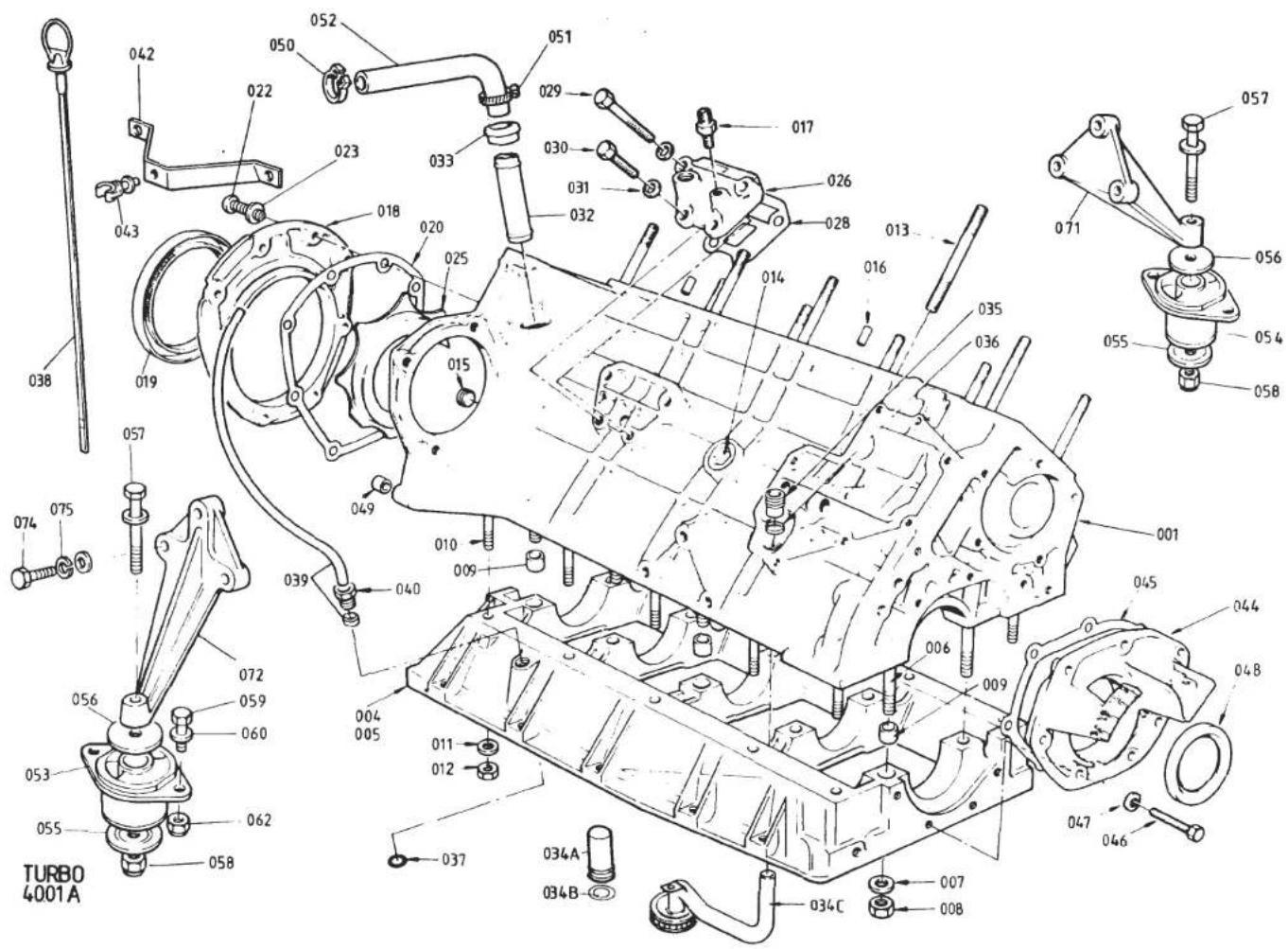


| ILLUSNO. | DESCRIPTION | PART NUMBER | QUANTITY | MAY 1991REMARKS | |
| DRYSUMP | WETSUMP | ||||
| 001 | Cylinder Block & Main Bearing Housing | A910E0984J | 1 | >Inc. Items Up to 012 | |
| Cylinder Block & Main Bearing Housing | B912E0750J | 1 | > | ||
| Cylinder Block & Main Bearing Housing | A910E9195J | 1 | H.C.> | ||
| Stud, M12 x 183, Block to MBH | A908E0225Z | 10 | Heater Only | ||
| Stud, M12 x 183, Block to MBH | A908E0225Z | 7 | )With A/C | ||
| Stud, M12 x 192, Block to MBH | A907E0224Z | 3 | ) | ||
| 006 | Stud, M12, Block to MBH | A907E0225Z | 10 | ||
| 007 | Washer, Flat, Block to MBH | A910E2383Z | 10 | 10 | |
| 008 | Nut, M12, Block to MBH | A910E6903Z | 10 | 10 | |
| 009 | Ring Dowel, Block to MBH | A911E0320F | 10 | 10 | |
| Stud, M8 x 47 Block to MBH | A910E1396K | 9 | |||
| Stud, M8 x 41 Block to MBH | A907E0128Z | 1 | |||
| 010 | Stud, M8, Block to MBH | A907E0226Z | 10 | ||
| 011 | Washer, Flat, Block to MBH | A075W4020Z | 10 | 10 | |
| 012 | Nut, M8, Block to MBH | A075W3021Z | 10 | 10 | |
| 013 | Stud, M12, Cylinder Head to Block | A907E0224Z | 10 | 10 | |
| 014 | Plug, 1" NPTF, Cylinder Block | A907E0528Z | 2 | 2 | |
| 015 | Plug, 1/4" BSP, Oil Gallery | A907E6063Z | 1 | 1 | |
| 016 | Spirol Pin, Cylinder Head to Block | A907E6007Z | 2 | 2 | |
| 017 | Union, Oil Pressure Gauge Take-Off | A907E0625Z | 1 | 1 | |
| 018 | Housing, Rear Crank Seal | A907E0599Y | 1 | 1 | R/B C907E0599Y |
| Housing, Rear Crank Seal | C907E0599Y | 1 | 1 | ||
| 019 | Seal, Crankshaft Rear, (Red) | A907E0631Z | 1 | 1 | R/B A912E2334F |
| Seal, Crankshaft Rear, (Black) | A912E2334F | 1 | |||
| 020 | Gasket, Rear Seal Housing | A907E0671Z | 1 | 1 | |
| 022 | Setscrew, M6 x 25, Rear Housing/Block | A075W1031F | 4 | 4 | R/B A075W7016Z |
| 023 | Washer, Flat, Rear Housing/Block | A075W4013Z | 4 | 4 | R/B A075W4065Z |
| Button Head Screw, Housing/Block & MBH | A075W7016Z | 8 | 8 | ||
| Washer, Thin, Housing/Block & MBH | A075W4065Z | 8 | 8 | ||
| 025 | Sprayshield | B907E0662Z | 1 | 1 | |
| 026 | Cover, Oil Gallery | B910E1400K | 1 | 1 | Std. |
| Cover, Oil Gallery | A910E2328K | 1 | ) | ||
| Switch, Oil Pressure, 17.6 PSI | A910E6866F | 1 | )H.C. | ||
| Sealing Washer, Switch | A910E6831F | 1 | ) Turbo 40.01A | ||
| d5p31 | Page 1 | ||||
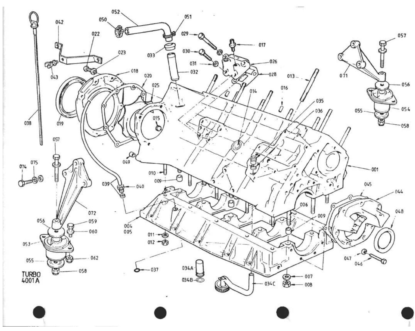
| ILLUS NO. | DESCRIPTION |  PART NUMBER PART NUMBER | QUANTITY | MAY 1991REMARKS | |
| DRYSUMP | WETSUMP | ||||
| 40.01A | |||||
| 028 | Gasket, Oil Gallery | A907E0438Z | 1 | 1 | |
| 029 | Bolt, M8 x 35, Oil Gallery Cover | A075W1041Z | 2 | 2 | |
| 030 | Setscrew, M8 x 20, Oil Gallery Cover | A075W1038Z | 2 | 2 | |
| 031 | Washer, Flat, Oil Gallery Cover | A075W4020Z | 4 | 4 | |
| 032 | Spout, Crankcase Breather | B907E0626Z | 1 | 1 | |
| 033 | Bush, Breather Spout | A907E0659Z | 1 | 1 | |
| 034A | Pipe, Oil Feed | B908E1282K | 1 | ||
| 034B | 'O' Ring, Oil Feed Pipe/MBH | A908E6420F | 1 | ||
| 034C | Pipe, Oil Pick Up | A907E0624Z | 1 | ||
| 035 | Union, Oil Pick Up/Feed Pipe | A907E0605Z | 1 | 1 | |
| 036 | Olive, Compression, Oil Pipe | A907E0606Z | 1 | 1 | |
| 037 | 'O' Ring, Dipstick Tube | A912E6398F | 1 | ||
| 038 | Dipstick | A910E1792F | 1 | ||
| 039 | Tube, Dipstick, (c/w Olive) | A910E9020K | 1 | Std. | |
| Tube, Dipstick, (c/w Olive) | A910E9038J | 1 | H.C. | ||
| 040 | Tube Nut, Dipstick Tube | A911E6378F | 1 | ||
| 042 | Bracket, Dipstick Tube to Plenum | B910E1793F | 1 | Std. | |
| Bracket, Dipstick Tube to Plenum | A910E1902F | 1 | H.C. | ||
| 043 | Clip, Plastic, Dipstick Tube Bracket | A910E6592F | 1 | ||
| 044 | Front Cover | A907E1230F | 1 | 1 | |
| 045 | Gasket, Front Cover | A907E0245Z | 1 | 1 | |
| 046 | Setscrew, M6 x 25, Front Cover | A075W1031Z | 7 | 7 | |
| 047 | Washer, Flat, Front Cover | A075W4013Z | 7 | 7 | |
| 048 | Seal, Crankshaft Front | B907E6010F | 1 | 1 | |
| 049 | Dowel, Engine to Clutch Housing | A907E6181Z | 2 | 2 | |
| 050 | Snapper Clip, Breather Hose | A075W6211Z | 1 | 1 | |
| 051 | Hose Clip, Breather Hose | A907E6085Z | 1 | 1 | |
| Hose, Breather, Crankcase/Oil Tank | B907E0636Z | 1 | |||
| Hose, Breather, Crankcase/Turbo Intake | B907E1795Z | 1 | R/B A910E1842F ) Std. Engine Only. | ||
| Hose, Breather, Crankcase/Turbo Intake | A910E1842F | 1 | ) For 'H.C.' See 43.03A | ||
| 052 | Hose, Breather, Crankcase/Air Filter | A911E0636F | 1 | ) | |
| Mounting Rubber, Engine | X046D6000F | 2 | R/B A085E6012F sets of 4 (inc.Trans.Mtg.) | ||
| Mounting Rubber, Engine, Blue | A085E6012F | 2 | Fixing Hole Cntr. 91mm.Up to VIN 82D 1008 | ||
| d5p32 | Turbo 40.01APage 2 | ||||

| ILLUS NO. | DESCRIPTION |  PART NUMBER PART NUMBER | QUANTITY | REMARKS | |
| DRYSUMP | WETSUMP | ||||
| Buffer Washer, Mtg. Brkt. to Rubber | A075W4006F | 2 | ) | ||
| Bolt, 7/16" UNF x 3 1/2 ", Mtg. Brkt/Rubber | A079W2084F | 2 | ) | ||
| Washer, Flat, Mtg. Brkt./Rubber | A075W4005F | 2 | ) | ||
| Nut, Nyloc, 7/16" UNF, Mtg. Brkt./Rubber | A075W3004F | 2 | )Use With Mtg. Rubber A085E6012F | ||
| Setscrew, M8 x 20, Mtg. Rubber/Chassis | A079W2084F | 2 | ) | ||
| Washer, Flat, Mtg. Rubber/Chassis | A075W4020F | 8 | ) | ||
| Nut, Nyloc, M8 | A075W3010F | 4 | ) | ||
| 053 | Mounting Rubber, Engine, RH, Blue | B085E6008F | 1 | 1 | >Fixing Hole Centres 82mm From |
| 054 | Mounting Rubber, Engine, LH, Pink | B085E6009F | 1 | 1 | >VIN 82D 1009 |
| 055 | Buffer Washer, Lower | A085E6010F | 2 | 2 | ) |
| 056 | Buffer Washer, Upper | A085E6011F | 2 | 2 | ) |
| 057 | Bolt, M12 x 100, Rubber to Mtg. Brkt. | A079W2072F | 2 | 2 | ) |
| 058 | Nut, Nyloc, M12, Rubber to Mtg. Brkt. | A075W3012F | 2 | 2 | )Use With Mtg. Rubber A085E6008/9F |
| 059 | Setscrew, M8 x 20, Rubber/Chassis | A075W1038F | 4 | 4 | ) |
| 060 | Washer, Flat | A075W4020F | 6 | 6 | ) |
| Washer, Spring | A075W4036F | 2 | 2 | ) | |
| 062 | Nut, Nyloc, M8 | A075W3010F | 2 | 2 | ) |
| 071 | Mounting Bracket, Engine, LH | A082E4079K | 1 | 1 | |
| Mounting Bracket, Engine, RH, With Relay Lever Pivot | A082E4078K | 1 | 1 | For Use With 0.86:1 Ratio Gear Change Relay Lever. If Replacing Earlier Fabricated Mounting Bracket, Replace Also Relay Lever (see 47.05A) | |
| Mounting Bracket, Engine, RH, With Relay Lever Pivot (inc. Bush) | A912E9022J | 1 | For Use With 1:1 Ratio Gear Change Relay Lever | ||
| Bush, Gear Change Relay Lever Pivot | A912E6593F | 1 | For Use With Mtg. Brkt. A912E9022J | ||
| 072 | Mounting Bracket, Engine, RH, Without Relay Lever Pivot | B082E4078K | 1 | ||
| Edge Finisher, Engine Mounting Brkt | C082U4775F | 40mm | For Use With Mtg. Brkt. B082E4078K R/B A082W7053F | ||
| 074 | Bolt, M8 x 40, Bracket to Engine | A075W2039D | 6 | 6 | |
| Setscrew, Cap Head, M8 x 35, Brkt. to Engine | A082W7053F | 6 | |||
| 075 | Washer, Spring, Bracket to Engine | A075W4036Z | 6 | 6 | Turbo 40.01A Page 3 |
| d5p33 | |||||

TURBO 4003A


| ILLUSNO. | DESCRIPTION | PART NUMBER | QUANTITY | REMARKS | |
| WETSUMP | |||||
| 40.03A | |||||
| 001 | Oil Sump | A910E1701K | 1 | ||
| 002 | Plug, Sump Drain | A036R6014Z | 1 | ||
| 003 | Washer, Sump Plug | A075W4055Z | 1 | ||
| 006 | Baffle, Sump | A910E9216J | 1 | ||
| 013 | Screw, Baffle to Sump | A912E6399F | 2 | ||
| 014 | Setscrew, M8 x 25, Sump to MBH | A075W1039Z | 3 | ||
| 015 | Bolt, M8 x 45, Sump to MBH | A075W2040Z | 3 | ||
| 016 | Bolt, M8 x 65, Sump to MBH | A075W2044Z | 1 | ||
| 018 | Bolt, M8 x 50, Sump to MBH | A075W2041Z | 3 | ||
| 019 | Nut, Nyloc, M8, Sump to MBH | A075W3010Z | 2 | ||
| 020 | Washer, Flat, Sump to MBH | A075W4020Z | 18 | ||
| 021 | Bolt, M8 x 30, Sump to MBH | A075W1040Z | 5 | ||
| 022 | Bolt, M8 x 80, Sump to MBH | A075W2045Z | 1 | ||

TURBO 40.05 A


| ILLUSNO. | DESCRIPTION |  PART NUMBER PART NUMBER | QUANTITY | MAY 1991REMARKS | |
| STD.ENGINE | H.C.ENGINE | ||||
| 001 | Cylinder Head Assembly | A910E0703J | 1 | >Inc. Items Up To & Inc. 024 | |
| Cylinder Head Assembly | A910E9057J | 1 | > | ||
| 005 | Core Plug, Small | A907E6038F | 6 | 6 | |
| 006 | Core Plug, Large, Rear | A907E6039Z | 1 | 1 | |
| 008 | Plug, 1/8" BSP, Socket | A907E6023Z | 2 | 2 | |
| 009 | Pipe, Heater Take-Off | A907E0486Z | 1 | 1 | |
| 013 | Guide, Inlet Valve, O/D Std. | F907E0315Y | ) | ) | |
| Guide, Inlet Valve, O/D + 0.001" | C907E0315Y | ) 8 | ) 8 | ||
| Guide, Inlet Valve, O/D + 0.002" | D907E0315Y | ) | ) | ||
| Guide, Inlet Valve, O/D + 0.005" | I907E0315Y | ) | ) | ||
| 015 | Guide, Exhaust Valve, O/D Std. | A910E0315F | > | > | |
| Guide, Exhaust Valve, O/D + 0.001" | B910E0315F | > 8 | > 8 | ||
| Guide, Exhaust Valve, O/D + 0.002" | C910E0315F | > | > | ||
| Guide, Exhaust Valve, O/D + 0.005" | D910E0315F | > | > | ||
| 018 | Circlip, Valve Guide | A907E6037Z | 16 | 16 | |
| 019 | Seat Insert, Inlet Valve, O/D Std. | B907E0312Y | ) | ||
| Seat Insert, Inlet Valve, O/D + 0.001" | C907E0312Y | ) 8 | |||
| Seat Insert, Inlet Valve, O/D + 0.002" | D907E0312Y | ) | |||
| Seat Insert, Inlet Valve, O/D + 0.005" | E907E0312Y | ) | |||
| Seat Insert, Inlet Valve, O/D Std. | C912E2010F | > | |||
| Seat Insert, Inlet Valve, O/D + 0.001" | C912E2011F | > 8 | |||
| Seat Insert, Inlet Valve, O/D + 0.002" | C912E2012F | > | |||
| Seat Insert, Inlet Valve, O/D + 0.005" | C912E2013F | > | |||
| 023 | Seat Insert, Exhaust Valve, O/D Std. | A910E1386F | ) | ) | |
| Seat Insert, Exhaust Valve, O/D + 0.001" | B910E1386F | ) 8 | ) 8 | ||
| Seat Insert, Exhaust Valve, O/D + 0.002" | C910E1386F | ) | ) | ||
| Seat Insert, Exhaust Valve, O/D + 0.005" | D910E1386F | ) | ) | ||
| d5p35 | Turbo 40.05APage 1 | ||||

TURBO 40.05 A


| ILLUSNO. | DESCRIPTION |  PART NUMBER PART NUMBER | QUANTITY | MAY 1391REMARKS | |
| STD.ENGINE | H.C.ENGINE | ||||
| 40.05A | |||||
| 024 | Stub Pipe, Water Outlet | A908E1281F | 1 | ||
| 025 | Adaptor, Water Outlet | A910E2403F | 1 | ||
| 027 | Roll Pin, Cyl. Head to Cam Hsg. | A075W6097Z | 2 | 2 | |
| 028 | 'O' Ring, Roll Pin | A907E6202Z | 2 | 2 | |
| 029 | Setscrew, Oil Gallery Plug | A075W1036Z | 1 | 1 | |
| 030 | 'O' Ring, Oil Gallery Plug | A907E6202Z | 1 | 1 | |
| 031 | Washer, Flat, Oil Gallery Plug | A075W4020Z | 1 | 1 | |
| 032 | Stud, M8, Cam Hsg. to Head | A911E0227Z | 4 | 4 | |
| 033 | Seat, Valve Spring | A907E0316Z | 16 | 16 | |
| 034 | Spring, Valve, Inner | A912E0023F | 16 | 16 | |
| 035 | Spring, Valve, Outer | A912E0022F | 16 | 16 | |
| 036 | Retainer, Valve Spring | A912E0021F | 16 | 16 | |
| 037 | Collet, Inlet Valve | A907E6040Z | 16 | 16 | |
| 038 | Collet, Exhaust Valve | A910E6377F | 16 | 16 | |
| 039 | Valve, Inlet | A912E0019F | 8 | 8 | |
| 040 | Valve, Exhaust | B910E1383F | 8 | 8 | |
| 041 | Gasket, Cylinder Head | B907E0026Z | 1 | 1 | |
| 042 | Washer, Cylinder Head to Block | A910E2383Z | 10 | 10 | |
| 043 | Nut, M12, Cylinder Head to Block | A910E6903Z | 10 | 10 | |
| 044 | Stud, Exhaust Manifold to Head | C907E0635F | 12 | 12 | |
| 046 | Stud, Inlet Manifold to Head | A907E1027K | 9 | 9 | |

TURBO (Prior '87 M.Y. H.C.) 40.07A
| ILLUS NO. | DESCRIPTION |  PART NUMBER PART NUMBER | QUANTITY | MAY 1991REMARKS | |
| PRIOR22911 | FROM22911 | ||||
| Eng. No. 22911 Built January 1986This Page Prior to '87 M.Y. H.C. | |||||
| 001 | Camshaft Housing, Exhaust | B911E1328K | 1 | ||
| Camshaft Housing, Exhaust | A912E2033K | 1 | |||
| 003 | Camshaft Housing, Inlet | B911E1329K | 1 | ||
| Camshaft Housing, Inlet | A912E2034K | 1 | |||
| 004 | Camshaft '107' | A912E0107F | 2 | 2 | |
| 005 | Woodruff Key, Pulley to Camshaft | A907E6025Z | 2 | 2 | |
| 006 | Plug, Camshaft Front | A907E6069F | 2 | 2 | |
| 008 | Thrust Washer, 0.173 - 0.175" | A907E0619Z | ) | ) | |
| Thrust Washer, 0.175 - 0.177" | A907E0620Z | 2 | 2 | Cam Endfloat Control | |
| Thrust Washer, 0.177 - 0.179" | A907E0621Z | ) | |||
| Thrust Washer, 0.179 - 0.181" | A907E0622Z | ) | ) | ||
| 011 | Dowel, Thrust Washer/Camshaft | A907E0476Z | 2 | 2 | |
| 012 | Setscrew, M10, Thrust Washer to Cam | A075W1046Z | 2 | 2 | |
| 013 | Washer, Spring | A075W4037Z | 2 | 2 | |
| 014 | Tappet | A026E0024Z | 16 | 16 | |
| 015 | Shim, Tappet (Selective) | 16 | 16 | See 40.07A Page 3 | |
| 016 | Rear Cover, Camshaft Housing | A907E0090Y | 2 | 2 | |
| 017 | 'O' Ring, Rear cover | A907E6027Z | 2 | 2 | |
| 020 | Washer, Large O/D | A075W4017Z | 8 | 8 | |
| 021 | Washer, Spring | A075W4035Z | 4 | 4 | |
| 023 | 'Torx' Bolt, Housing to Head | B911E1311F | 16 | 16 | |
| 024 | Washer, Flat, Housing to Head | A075W4020Z | 4 | 4 | |
| 025 | Nut, M8, Housing to Head | A075W3021Z | 4 | 4 | |
| 026 | Stud, Cam Cover to Housing | A912E1363F | 6 | 6 | |
| 027 | Screw, Chromed, Cam Cover to Hsg. | A911E1333F | 6 | 6 | |
| 028 | Rubber Washer, Cam Cover Screw | A912E6406F | 6 | 6 | |
| Spirol Pin, Gasket Location | A079W6245F | 8 | |||
| 029 | Gasket, Cam Cover to Hsg. | A911E0001F | 2 | R/B A912E2040F | |
| Gasket, Cam Cover to Hsg. | A912E2040F | 2 | 2 | ||
| Turbo (Prior to '87 M.Y. H.C.) 40.07APage 1 | |||||
| d5p37 | |||||

TURBO (Prior '87 M.Y. H.C.) 40.07A
| ILLUSNO. | DESCRIPTION | PART NUMBER | QUANTITY | MAY 1991 | |
| PRIOR22911 | FROM22911 | REMARKS | |||
| 40.07A | Eng. No. 22911 Built January 1986This Page Prior to '87 M.Y. H.C. | ||||
| 030 | Cam Cover, Inlet, Without Filler | A911E0301K | 1 | Dry Sump Only | |
| Cam Cover, Inlet, With Filler | A910E0992K | 1 | R/B B910E0992K | ||
| Cam Cover, Inlet, With Filler | B910E0992K | 1 | Wet Sump. With Provision for Throttle Return Spring Bracket R/B C910E0992K | ||
| 032 | Cam Cover, Inlet, With Filler | C910E0992K | 1 | 1 | R/B B911E0301K |
| Cam Cover, Exhaust | A911E0301K | 1 | |||
| Cam Cover, Exhaust | B911E0301K | 1 | 1 | ||
| Plug, M20, Torx Bolt Access | A910E1690F | 10 | With Under Cut Thread. R/B A9116343F with Dowty Washer A910E6553F | ||
| 034 | Washer, Fibre, Used With A910E1690F | A911E6344F | 10 | R/B A910E6553F | |
| Plug, M20, Torx Bolt Access | A911E6343F | 10 | 10 | ||
| 035 | Washer, 'Dowty', Plug Sealing | A910E6553F | 10 | ||
| 'O' Ring, Plug Sealing | A912E6694F | 1 | |||
| 036 | Oil Seal, Camshaft Front | B907E6042F | 2 | 2 | |
| 037 | Snubber, Inlet Cam Pulley | A907E1107F | 1 | 1 | |
| 038 | Eccentric Adjuster, Snubber | A907E1108F | 1 | 1 | |
| 039 | Stud, Snubber Fixing | A907E1027K | 2 | 2 | |
| 040 | Washer, Flat, Snubber Fixing | A075W4020Z | 2 | 2 | |
| 041 | Nut, M8, Snubber Fixing | A075W3021Z | 2 | 2 | |
| 043 | Cap, Oil Filler | A026E0415Z | 1 | 1 | Wet Sump Only |
| 044 | Setscrew, M5 x 12, Cap Retention | A075W1021Z | 1 | 1 | |
| 045 | Washer, Flat, Cap Retention | A075W4013Z | 1 | 1 | |
| 046 | Washer, Shakeproof, Cap Retention | A075W4046Z | 1 | 1 | |
| Gasket, Filler Cap | A026E0325Z | 1 | 1 | ||
| d5p38 | Turbo (Prior to '87 M.Y. H.C.) 40.07A Page 2 | ||||

TURBO (Prior '87 M.Y. H.C.) 4007A
40.07A
Item 015
TAPPET SHIMS
| Shim | Part No. | Shim | Part No. | Shim | Part No. | Shim | Part No. |
| 0.060in | A026E6160Z | 0.083in | A026E6183Z | 0.106in | A026E6206Z | 0.129in | A026E6229Z |
| 0.061in | A026E6161Z | 0.084in | A026E6184Z | 0.107in | A026E6207Z | 0.130in | A026E6230Z |
| 0.062in | A026E6162Z | 0.085in | A026E6185Z | 0.108in | A026E6208Z | 0.131in | A026E6231Z |
| 0.063in | A026E6163Z | 0.086in | A026E6186Z | 0.109in | A026E6209Z | 0.132in | A026E6232Z |
| 0.064in | A026E6164Z | 0.087in | A026E6187Z | 0.110in | A026E6210Z | 0.133in | A026E6233Z |
| 0.065in | A026E6165Z | 0.088in | A026E6188Z | 0.111in | A026E6211Z | 0.134in | A026E6234Z |
| 0.066in | A026E6166Z | 0.089in | A026E6189Z | 0.112in | A026E6212Z | 0.135in | A026E6235Z |
| 0.067in | A026E6167Z | 0.090in | A026E6190Z | 0.113in | A026E6213Z | 0.136in | A026E6236Z |
| 0.068in | A026E6168Z | 0.091in | A026E6191Z | 0.114in | A026E6214Z | 0.137in | A026E6237Z |
| 0.069in | A026E6169Z | 0.092in | A026E6192Z | 0.115in | A026E6215Z | 0.138in | A026E6238Z |
| 0.070in | A026E6170Z | 0.093in | A026E6193Z | 0.116in | A026E6216Z | 0.139in | A026E6239Z |
| 0.071in | A026E6171Z | 0.094in | A026E6194Z | 0.117in | A026E6217Z | 0.140in | A026E6240Z |
| 0.072in | A026E6172Z | 0.095in | A026E6195Z | 0.118in | A026E6218Z | 0.141in | A026E6241Z |
| 0.073in | A026E6173Z | 0.096in | A026E6196Z | 0.119in | A026E6219Z | 0.142in | A026E6242Z |
| 0.074in | A026E6174Z | 0.097in | A026E6197Z | 0.120in | A026E6220Z | 0.143in | A026E6243Z |
| 0.075in | A026E6175Z | 0.098in | A026E6198Z | 0.121in | A026E6221Z | 0.144in | A026E6244Z |
| 0.076in | A026E6176Z | 0.099in | A026E6199Z | 0.122in | A026E6222Z | 0.145in | A026E6245Z |
| 0.077in | A026E6177Z | 0.100in | A026E6200Z | 0.123in | A026E6223Z | 0.146in | A026E6246Z |
| 0.078in | A026E6178Z | 0.101in | A026E6201Z | 0.124in | A026E6224Z | 0.147in | A026E6247Z |
| 0.079in | A026E6179Z | 0.102in | A026E6202Z | 0.125in | A026E6225Z | 0.148in | A026E6248Z |
| 0.080in | A026E6180Z | 0.103in | A026E6203Z | 0.126in | A026E6226Z | 0.149in | A026E6249Z |
| 0.081in | A026E6181Z | 0.104in | A026E6204Z | 0.127in | A026E6227Z | 0.150in | A026E6250Z |
| 0.082in | A026E6182Z | 0.105in | A026E6205Z | 0.128in | A026E6228Z |
TU6AAB
Turbo 40.07A
Page 3
FEB 1987

TURBO ('87 M.Y. HC.)
40.07B


| ILLUSNO. | DESCRIPTION | PART NUMBER | QUANTITY | MAY 1991REMARKS | |
| '87 M.YH.C. | |||||
| 40.07B | |||||
| 1 | Camshaft Housing, Inlet | A912E2034K | 1 | ||
| 2 | Camshaft Housing, Exhaust | A912E2033K | 1 | ||
| 3 | Nut, M8, Cam Housing to Head | A075W3021Z | 4 | ||
| 4 | Washer, 8mm, Cam Housing to Head | A075W4020Z | 4 | ||
| 5 | Torx Bolt, Cam Housing to Head | B911E1311F | 16 | ||
| 6 | Plug, M20, Torx Bolt Access | A911E6343F | 10 | ||
| 7 | 'O' Ring, Access Plug | A912E6694F | 10 | ||
| 8 | Tappet | A026E0024Z | 16 | ||
| 9 | Shim, Tappet | 16 | see 40.07A Page 3 | ||
| 10 | Thrust Washer, 0.173 - 0.175" | A907E0619Z | ) | ||
| Thrust Washer, 0.175 - 0.177" | A907E0620Z | ) 2 | Camshaft Endfloat Control | ||
| Thrust Washer, 0.177 - 0.179" | A907E0621Z | ) | |||
| Thrust Washer, 0.179 - 0.181" | A907E0622Z | ) | |||
| 14 | Dowel, Thrust Washer/Camshaft | A907E0476Z | 2 | ||
| 15 | Setscrew, M10, Thrust Washer to Camshaft | A075W1046Z | 2 | ||
| 16 | Spring Washer, Thrust Washer to Camshaft | A075W4037Z | 2 | ||
| 17 | Rear Cover, Camshaft Housing | A907E0090Z | 2 | ||
| 18 | 'O' Ring, Rear Cover | A907E6027Z | 2 | ||
| 19 | Stud, Cam Housing Rear | A912E2043F | 4 | ||
| 21 | Bracket, Diffuser Support | A910E2233K | 1 | ||
| Washer, Plain, Bracket to Diffuser | A075W4013Z | 1 | |||
| Nut, Nyloc, M6, Bracket to Diffuser | A075W3020Z | 1 | |||
| 22 | Camshaft, (Type '107') | A912E0107Z | 2 | ||
| 23 | Woodruff Key, Camshaft Pulley | A907E6025Z | 2 | ||
| 24 | Oil Seal, Camshaft Front | B907E6042F | 2 | ||
| 25 | Blanking Plug, Camshaft Front | A907E6069F | 2 | ||
| 26 | Cam Cover, Inlet, Red | A912E2277K | 1 | ||
| 27 | Cam Cover, Exhaust, Red | A912E2278K | 1 | ||
| 28 | Screw, Cam Cover Fix | B912E2037F | 6 | ||
| 29 | 'O' Ring, Cam Cover Fixing Screws | A912E6695F | 6 | ||
| 30 | Gasket, Cam Cover to Housing | A912E2040F | 2 | ||
| 31 | Spirol Pin, Gasket Location | A079W6245F | 8 | Turbo ('87 M.Y. H.C.) | |
| 32 | Oil Filler Cap Inc. Seal | A910E6779F | 1 | 40.07B | |
| d5p74 | |||||
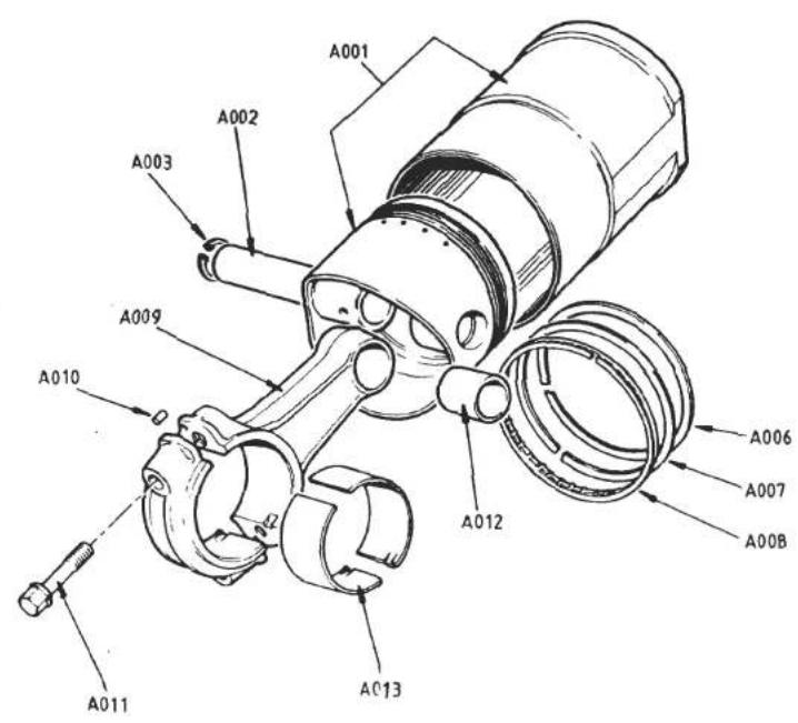
TURBO
40.09A


| ILLUS NO. | DESCRIPTION |  PART NUMBER PART NUMBER | QUANTITY |  REMARKS REMARKS | |
| STD. ENGINE | '87 M.Y H.C. | ||||
| 40.09A | |||||
| A001 | Piston & Liner Assembly,(5mm Oil Control Ring) | B910E0778F | 4 | R/B B910E6919F | |
| Piston & Liner Assembly,(4mm Oil Control Ring) | B910E6919F | 4 | Includes Items up to A008 inc. | ||
| Piston & Liner Assembly | A910E9192F | 4 | " " " " " " | ||
| A002 | Gudgeon Pin | B907E0405H | 4 | ||
| Gudgeon Pin | A910E2170H | 4 | |||
| A003 | Circlip, Gudgeon Pin | A907E6022H | 8 | ||
| Circlip, Gudgeon Pin | A910E6781F | 8 | |||
| A006 | Compression Ring, Top | A911E0401H | 4 | Internal Top Bevel | |
| Compression Ring, Top | A910E2193F | 4 | Internal Top & Bottom Bevel | ||
| A007 | Compression Ring, Second | A911E0402H | 4 | Internal Top Step | |
| Compression Ring, Second | A910E2194F | 4 | Plain | ||
| A008 | Oil Control Ring (5mm Width) | B907E0404H | 4 | R/B A912E6985F | |
| Oil Control Ring (5mm Width) | A912E6985F | 4 | |||
| Oil Control Ring (4mm Width) | A910E6923F | 4 | Use With Piston B910E6919F | ||
| Oil Control Ring | A910E2195F | 4 | |||
| A009 | Connecting Rod | A910E0714F | 4 | R/B B910E0714F | |
| Connecting Rod | B910E0714F | 4 | 4 | Includes Items up to A012 inc. | |
| A010 | Dowel, Cap to Rod | A907E0339H | 8 | 8 | |
| A011 | Bolt, Cap to Rod | A907E0344H | 8 | 8 | |
| A012 | Bush, Small End | A907E0357H | 4 | 4 | |
| A013 | Bearing Shell, 'Big End' STD. | A907E0342S | ) | ||
| Bearing Shell, 'Big End' - 0.010" | A907E0540Z | ) 8 | 8 | ||
| Bearing Shell, 'Big End' - 0.020" | A907E0541Z | ) | |||
REMARKS
Turbo 40.09A
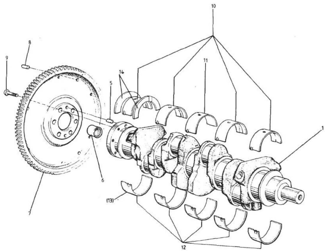
TURBO 40.11A


| ILLUSNO. | DESCRIPTION | PART NUMBER | QUANTITY | MAY 1991REMARKS | |
| ALL | |||||
| 40.11A | |||||
| 1 | Crankshaft (Including Dowels & Spigot Brg.) | A910E0897J | 1 | R/B A912E9234JInc.Adaptor A910B6902F | |
| Crankshaft (Including Dowels) | A912E9234J | 1 | |||
| 5 | Dowel, Crank to Flywheel | A907E6015F | 2 | ||
| 6 | Spigot Bearing | A907E6319F | 1 | ||
| 7 | Flywheel (Integral ring gear) | B910E1432F | 1 | ||
| 8 | Dowel, Flywheel to Clutch | A907E6084Z | 3 | ||
| 9 | Bolt, Flywheel to Crank | A907E6020Z | 6 | ||
| 10 | Shell, Main Bearing, Std. I/D, Std. O/D | A907E0336Z | 4 | (Groove/Hole) Upper, except Centre(Plain/Hole) Upper, Centre(Plain) Lower. Qty. 5 from EngineNo. 20875(Plain/Notch) Rear Lower* up to EngineNo. 20874 | |
| 11 | " " " " " " " " | A911E1315F | 1 | ||
| 12 | " " " " " " " " | A907E1170F | 4/5 | ||
| 13 | " " " " " " " " | A912E1993S | 1 | ||
| Shell, Main Bearing - 0.010" I/D, Std. O/D | A907E0538Z | 4 | (Groove/Hole) Upper, except Centre(Plain/Hole) Upper, Centre(Plain) Lower. Qty. 5 from EngineNo. 20875(Plain/Notch) Rear Lower* up to EngineNo. 20874 | ||
| " " " " " " " " | A911E1317F | 1 | |||
| " " " " " " " " | A907E1172F | 4/5 | |||
| " " " " " " " " | A912E1994S | 1 | |||
| Shell, Main Bearing - 0.020" I/D, Std. O/D | A907E0539Z | 4 | (Groove/Hole) Upper, except Centre(Plain/Hole) Upper, Centre(Plain) Lower. Qty. 5 from EngineNo. 20875(Plain/Notch) Rear Lower* up to EngineNo. 20874 | ||
| " " " " " " " " | A911E1318F | 1 | |||
| " " " " " " " " | A907E1173F | 4/5 | |||
| " " " " " " " " | A912E1995S | 1 | |||
| *See Service Notes Section EA. 28 | |||||
| d6p26 | Turbo 40.11APage 1 | ||||

TURBO 40.11A


| ILLUSNO. | DESCRIPTION |  PART NUMBER PART NUMBER | QUANTITY | REMARKS | |
| ALL | |||||
| 40.11A | |||||
| Shell, Main Bearing, Std. I/D, + 0.015" O/D" " " " " " " " " " " " " " " " " " " " " " " " " " " " " " " " " " " " " " " " " " " " " " " " " " " " " " " " " " " " " " " " " " " " " " " " " " " " " " " " " " " " " " " " " " " " " " " " " " " " " | A907E0675ZA911E1316FA907E1171FA912E1996S | 414/51 | (Groove/Hole) Upper, except Centre(Plain/Hole) Upper, Centre(Plain) Lower. Qty. 5 from EngineNo. 20875(Plain/Notch) Rear Lower* up to EngineNo. 20874 | ||
| Shell, Main Bearing, - 0.010" I/D + 0.015" O/D" " " " " " " " " " " " " " " " " " " " " " " " " " " " " " " " " " " " " " " " " " " " " " " " " " " " " " " " " " " " " " " " " " " " " " " " " " " " " " " " " " " " " " " " " | B907E0675ZB911E1316FB907E1171FA912E1997S | 414/51 | (Groove/Hole) Upper, except Centre(Plain/Hole) Upper, Centre(Plain) Lower. Qty. 5 from EngineNo. 20875(Plain/Notch) Rear Lower* up to EngineNo. 20874 | ||
| Shell, Main Bearing, - 0.020" I/D + 0.015" O/D" " " " " " " " " " " " " " " " " " " " " " " " " " " " " " " " " " " " " " " " " " " " " " " " " " " " " " " " " " " " " " " " " " " " " " " " " " " " " " " " " " " " " | C907E0675ZC911E1316FC907E1171FA912E1998S | 414/51 | (Groove/Hole) Upper, except Centre(Plain/Hole) Upper, Centre(Plain) Lower. Qty. 5 from EngineNo. 20875(Plain/Notch) Rear Lower* up to EngineNo. 20874 | ||
| 14 | Thrust Washer, Crank, Std.Thrust Washer, Crank, + 0.0025"Thrust Washer, Crank, + 0.0050"Thrust Washer, Crank, + 0.0075"Thrust Washer, Crank, + 0.0100" | A907E1000ZA907E1001ZA907E1002ZA907E1003ZA907E1004Z | ) )2 ) | ||
| *See Sevice Notes Section EA. 28 | |||||
| d6p27 | Turbo 40.11APage 2 | ||||

| ILLUSNO. | DESCRIPTION |  PART NUMBER PART NUMBER | QUANTITY | MAY 1991REMARKS | |
| PRIOR'87 M.Y | '87 M.YON | ||||
| 40.13A | |||||
| Water Pump Assembly, inc. Pulley | B910E0946J | 1 | Dry Sump(Pulley Pressed Direct onto Shaft) | ||
| 2 | Water Pump Assembly, (less pulley) | B910E9001J | 1 | Inc. Hub, Elbow & Plug )Wet | |
| 6 | Hub, Pump Pulley | A907E6295Z | 1 | )Sump | |
| 7 | Elbow, Heater Return | A911E1431F | 1 | ||
| 9 | Plug, Blanking | A910E1644K | 1 | If Fitted | |
| 10 | Bolt, M6 x 75, Pump to Block | A075W2036F | 1 | ||
| 12 | Setscrew, M6 x 25, Pump to Block | A075W2027Z | 4 | ||
| 13 | Washer, Flat, Pump Fixing | A075W4013Z | 5 | ||
| 14 | Gasket, Pump to Block | A907E0246Z | 1 | ||
| 17 | Water Pump Assy. | B912E9021J | 1 | inc. pulley hub & adaptor pipes | |
| 18 | Hub, Water Pump Pulley | A907E6295Z | 1 | ||
| 19 | Elbow Pipe, Heater Return | A911E1431F | 1 | ||
| 20 | Adaptor Pipe, Thermostat Housing | A910E1909F | 1 | ||
| 21 | Gasket, Water Pump to Block | A907E0246Z | 1 | ||
| 22 | Bolt, M6 x 30, Pump to Block | A075W2028Z | 2 | ||
| 24 | Bolt, M6 x 35, Pump to Block | A075W2029Z | 2 | ||
| 25 | Bolt, M6 x 55, Pump to Block | A075W2034Z | 1 | ||
| 26 | Washer, Flat, Water Pump Fixings | A075W4013Z | 5 | ||
| 27 | Hose, Inlet Manifold to Pump | A912E1896F | 1 | ||
| 28 | Hose Clip, 32/50 | A079K6019F | 2 | ||
| 29 | Elbow Hose, Cylinder Head to Pump | A912E1837F | 1 | ||
| 30 | Hose Clip | A079K6018F | 2 | ||
| 31 | Thermostat Cover Outlet Elbow | B912E1829P | 1 | ||
| 32 | Gasket, Thermostat Cover | A026E6102Z | 1 | ||
| 33 | Setscrew, M8 x 25, Thermostat Cover | A075W1039Z | 2 | ||
| 34 | Washer, Flat, Thermostat Cover | A075W4020Z | 2 | ||
| 35 | Thermal Transmitter, Temp Gauge | A050M6136W | 1 | ||
| 37 | Thermostat, 74°C | A075K0121F | 1 | Hot Climates | |
| Thermostat, 82°C | A907E6046Z | 1 | Temperate Climates | ||
| d5p39 | Turbo 40.13A | ||||

| ILLUSNO. | DESCRIPTION |  PART NUMBER PART NUMBER | QUANTITY | MAI 1991REMARKS | |
| DRYSUMP | WETSUMP | ||||
| 40.15A | |||||
| 001 | Auxiliary Housing and "Oil Pump" Assembly | A910E0983J | 1 | )Includes Items | |
| Auxiliary Housing and Oil Pump Assembly | G907E0747F | 1 | Without A/C up to & inc. 018 | ||
| Auxiliary Housing and Oil Pump Assembly | B907E0859F | 2 | 1 | With A/C ) | |
| Auxiliary Housing | B910E1584K | 1 | |||
| Auxiliary Housing | F907E0437H | 1 | 1 | Without A/C | |
| Auxiliary Housing | A907E1092H | 3 | 1 | With A/C | |
| Plug, 3/8" BSP, Aux. Hsg. Oilway Blanking | A910E1598F | 6 | |||
| Plug, 1⁄2" BSP, Aux. Hsg. Oilway Blanking | A910E1643F | 4 | |||
| 002 | "Oil Pump", Housing, | C907E0443F | 1 | R/B E907E0803H | |
| Oil Pump Housing Assembly | E907E0803H | 1 | inc. relief valve and dist. stud | ||
| 003 | Stud, Distributor Clamp | A907E0503H | 1 | 1 | |
| Spacer Tube | A910E1675K | 1 | ) | ||
| Blanking Plug | A907E1324F | 1 | )Replaces oil pressure relief valve | ||
| 'O' Ring, Blanking Plug | A907E6099F | 1 | ) | ||
| 004 | Dowel, Pump Body to Aux. Hsg. | A907E0530F | 2 | 2 | |
| 005 | Gasket, Pump Body to Aux. Hsg. | A907E0474H | 1 | 1 | |
| 006 | Bolt, M6 x 30, Pump to Aux. Hsg. | A075W2028F | 6 | 6 | |
| 007 | Washer, Spring, Pump to Aux. Hsg. | A075W4035H | 6 | ||
| 008 | Washer, Flat, Pump to Aux. Hsg. | A075W4013F | 6 | 6 | |
| Shaft & Rotor Assembly | B907E0785F | 1 | Inc. key & circlip | ||
| Auxiliary Shaft | A910E1585K | 1 | |||
| 010 | Auxiliary Shaft | E907E0291H | 1 | ||
| 011 | Rotor, Oil Pump | A907E0472F | 1 | 1 | |
| 012 | Woodruff Key, Oil Pump Rotor | A907E6001F | 1 | 1 | |
| 013 | Circlip, Rotor to Shaft | A907E6101F | 1 | 1 | |
| 014 | Annulus, Oil Pump | A907E0473H | 1 | ||
| 015 | Circlip, Pulley Abutment | A907E6067H | 1 | 1 | |
| 016 | Spring, Dist. Drive/Aux. Shaft | B907E0135F | 1 | ||
| Spring, Dist. Drive/Aux. Shaft | A907E0192H | 1 | |||
| 017 | Oil Seal, Aux. Shaft Front | A907E6064H | 1 | 1 | |
| Oil Seal, Aux. Shaft Rear | A910E6383F | 1 | |||
| 018 | Adaptor Union, Oil Filter | A907E0249H | 1 | 1 | |
| 019 | Gasket, Aux. Hsg. to Cylinder Block | D907E0442F | 1 | 1 | |
| d5p40 | Turbo 40.15APage 1 | ||||
) Includes Items
Without A/C )up to & inc. 018
With A/C )
Without A/C
With A/C
R/B E907E0803H
inc. relief valve and dist. stud
)
)Replaces oil pressure relief valve

| ILLUSNO. | DESCRIPTION |  PART NUMBER PART NUMBER | QUANTITY | MAY 1991REMARKS | |
| DRYSUMP | WETSUMP | ||||
| 020 | Setscrew, M8 x 25, Housing to Block | A075W1039Z | 3 | 3 | Wet |
| 021 | Bolt, M8 x 40, Housing to Block | A075W2039Z | 3 | 3 | Use Torx Bolt A912E1692K Sump at front lower location if insufficient hex. head clearance |
| 022 | Bolt, M8 x 60, Housing to Block | A075W2043Z | 2 | 2 | |
| 023 | Bolt, M8 x 90, Housing to Block | A075W2048Z | 1 | 1 | |
| 025 | Washer, Flat, Aux. Hsg. Fixings | A075W4020Z | 9 | 9 | |
| 020A | Setscrew, M8 x 25, Housing to Block | A075W1039Z | 2 | > | |
| 021A | Bolt, M8 x 40, Housing to Block | A075W2039Z | 3 | > | |
| 022A | Bolt, M8 x 60, Housing to Block | A075W2043Z | 1 | > | |
| 023A | Bolt, M8 x 90, Alt. Brkt/Housing/Block | A075W2048Z | 1 | Used with Alt/Brkt A910E1760K > With | |
| Bolt, M8 x 100, Alt. Brkt/Housing/Block | A075W2049Z | 1 | Used with Alt/Brkt B910E1760K > A/C | ||
| Bolt, M8 x 115, Alt. Brkt/Housing/Block | A075W2047Z | 1 | Used with Alt/Brkt C910E1760K > | ||
| 023B | Bolt, M8 x 90, Alt. Brkt/Housing/Block | A075W2048Z | 1 | Used with Alt/Brkt A910E1760K > | |
| Bolt, M8 x 100, Alt. Brkt/Housing/Block | A075W2049Z | 1 | Used with Alt/Brkt B910E1760K > | ||
| Bolt, S/H, M8 x 100, Alt. Brkt/Housing/Block | A08ZW7043F | 1 | Used with Alt/Brkt C910E1760K > | ||
| 024A | Bolt, M8 x 100, Alt. Brkt/Housing/Block | A075W2049Z | 1 | Use with Alt/Brkt A/B910E1760K> | |
| Bolt, M8 x 105, Alt. Brkt/Housing/Block | A075W2077Z | 1 | Used with Alt/Brkt C910E1760K > | ||
| 025 | Washer, Flat, Aux. Hsg. Fixings | A075W4020Z | 7/9 | 7 with A/C > | |
| 026 | Mounting Bracket, Alternator | A910E1760K | 1 | R/B C910E1760K ) | |
| Mounting Bracket, Alternator | B910E1760K | 1 | R/B C910E1760K ) | ||
| Mounting Bracket, Alternator | C910E1760K | 1 | With Plinth ) With | ||
| 027 | Spacer, Alt. Brkt. to Hsg. | A907E1094F | 1 | ) A/C | |
| 028 | Bracket, A/C Compressor Rear | B912E1379K | 1 | ||
| 029 | Spacer, Comp. Brkt. to Hsg. | B912E1378K | 1 | ||
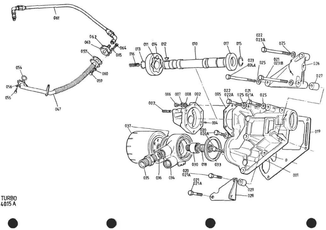
| ILLUSNO. | DESCRIPTION | PART NUMBER | QUANTITY | REMARKS | |
| DRYSUMP | WETSUMP | ||||
| 40.15A | |||||
| 030 | Extension Union, Oil Filter | B907E0571F | 1 | ||
| 033 | Sealing Ring, Adaptor/Housing | A907E6167F | 1 | ||
| 034 | Adaptor, Oil Cooler | A907E1248K | 1 | ||
| 035 | Union, Oil Cooler Pipes | A907E6300F | 2 | ||
| 036 | Washer, Union to Adaptor | B907E6301F | 2 | ||
| 037 | Oil Filter (inc. Sealing Ring) | A907E6000W | 1 | 1 | Prior to '86 M.Y.'86 M.Y. On. Use A907E6000W in Service |
| Oil Filter (inc. Sealing Ring) | B907E6000W | 1 | |||
| 047 | Pipe, Oil Drain, Turbo to Sump | C910E0979J | 1 | ||
| Pipe, Oil Drain, Turbo to Sump | B910E0990J | 1 | R/B C910E0990F | ||
| Pipe, Oil Drain, Turbo to Sump | C910E0990F | 1 | |||
| 054 | 'O' Ring, Drain Pipe to Sump | A910E6491F | 1 | 1 | |
| 055 | Setscrew, M6 x 16, Pipe to Sump | A075W1028Z | 2 | 2 | |
| 056 | Washer, Spring, Pipe to Sump | A075W4035Z | 2 | 2 | |
| 057 | Gasket, Drain Pipe to Turbo | A910E6375H | 1 | 1 | |
| 059 | Setscrew, M8 x 20, Pipe to Turbo | A075W1038Z | 2 | 2 | |
| 060 | Washer, Spring, Pipe to Turbo | A075W4036Z | 2 | 2 | |
| 061 | Hose Assembly, Turbo Oil Feed | A910E1403F | 1 | 1 | R/B A910E2216F |
| Hose Assembly, Turbo Oil Feed | A910E2216F | 1 | 1 | ||
| 062 | Flange Adaptor, Turbo to Oil Feed Hose | A910E1545F | 1 | 1 | |
| 063 | Gasket, Flange Adaptor to Turbo | A910E6374H | 1 | 1 | |
| 064 | Setscrew, M8 x 20, Flange to Turbo | A075W1038Z | 2 | 2 | |
| 065 | Washer, Spring, Flange to Turbo | A075W4036Z | 2 | 2 | |
| Turbo 40.15APage 3 | |||||
| d5p42 | |||||


| ILLUSNO. | DESCRIPTION | PART NUMBER | QUANTITY | MAY 1991REMARKS | |
| DRYSUMP | |||||
| 40.15B | |||||
| 1 | Scavenge Manifold | A910E1452F | 1 | ||
| Gasket, Scavenge Manifold to Sump | A910E1468F | 1 | |||
| Stud, M6 x 87, Scavenge Manifold to Sump | A910E1671F | 5 | |||
| Stud, M6 x 67, Scavenge Nanifold to Sump | A910E1595K | 3 | |||
| Nut, M6, Manifold to Sump | A075W3020Z | 8 | |||
| Bolt, M6, Manifold to Sump | A075W1031F | 2 | |||
| Washer, 6mm, Manifold to Sump | A075W4013Z | 10 | |||
| Stud, M6 x 116, Manifold to Pump | A910E1500K | 4 | |||
| Stud, M6 x 123, Manifold to Pump | A910E1501K | 2 | |||
| Loctite 501, Studs to Manifold | A/R | ||||
| 2 | Stud, M6, Oil Inlet Pipe to Manifold | A912E0063F | 1 | ||
| 3 | Oil Pump Assembly | A910E0998J | 1 | Complete Pump Assembly but less ScavengeManifold, Pulley and Fixings | |
| Nut, M6, Pump to Manifold | A075W3020Z | 6 | |||
| Washer, 6mm, Pump to Manifold | A075W4013Z | 6 | |||
| 4 | Union, Scavenge Pump Outlet | A910E1621K | 1 | ||
| 5 | "Dowty" Washer, Outlet Union | B907E6301F | 1 | ||
| 6 | Pulley, Oil Pump, - 0.010" Diameter | A910E1705F | ) | No Dots | |
| Pulley, Oil Pump, Standard | A910E1706F | ) 1 | One Dot on Pulley Rim | ||
| Pulley, Oil Pump, + 0.010" Diameter | A910E1707F | ) | Two Dots on Pulley Rim | ||
| 7 | Key, Pulley to Shaft | B910E6386F | 1 | ||
| 8 | Washer, Pulley Rear/Shaft | A910E1711F | 1 | ||
| 9 | Washer, Conical, Pulley Ret. | A910E1708F | 1 | ||
| Oil Seal, Pump Shaft Front | A910E6383F | 1 | |||
| 10 | Bolt, Socket Head, Pulley Ret. | A075W7026F | 1 | ||
| Belt, Oil Pump Drive -9/-8 | A910E6659F | ) | |||
| Belt, Oil Pump Drive -7/-6/-5 | A910E6660F | ) | |||
| Belt, Oil Pump Drive -4/-3/-2 | A910E6661F | ) | |||
| Belt, Oil Pump Drive -1/std/+1 | A910E6384F | ) 1 | |||
| Belt, Oil Pump Drive +2/+3 | A910E6662F | ) | |||
| Belt, Oil Pump Drive +4/+5/+6 | A910E6663F | ) | |||
| Belt, Oil Pump Drive +7/+8/+9 | A910E6664F | ) | |||
| Belt, Oil Pump Drive +10/+11/+12 | A910E6665F | ) | |||
| 11 | Pipe, Oil Tank Hose to Pump | A910E0982J | 1 | Turbo (Dry Sump) 40.15BPage 1 | |
| d5p43 | |||||


| ILLUSNO. | DESCRIPTION | PART NUMBER | QUANTITY | MAY 1991REMARKS | |
| DRYSUMP | |||||
| 12 | 'O' Ring, Pipe to Pump | A910E6526F | 1 | ||
| Nut, M6, Nyloc, Pipe to Pump | A075W3009Z | 1 | |||
| Washer, 6mm | A075W4013Z | 1 | |||
| 13 | Support Bracket, Oil Pipe | A910E098LJ | 1 | ||
| Setscrew, M6 x 18, Oil Pipe to Bracket | A075W1029Z | 1 | |||
| Washer, Shakeproof | A075W4046Z | 1 | |||
| 14 | Oil Tank | A910E0942J | 1 | ||
| 15 | Bracket, Oil Tank Upper | B082U4739K | 1 | ||
| Setscrew, M8 x 25, Tank to Bracket | A075W1039Z | 2 | |||
| Washer, Flat, Tank to Bracket | A075W4020Z | 4 | |||
| Nut, Nyloc, M8 Tank to Bracket | A075W3010Z | 2 | |||
| 16 | Bracket, Oil Tank Lower Front | B082U4730K | 1 | ||
| 17 | Bracket, Oil Tank Lower Rear | A082U4731K | 1 | ||
| Setscrew, M8 x 25 | A075W1039Z | 6 | ) Oil Tank to Brkts. and Brkts. to Body | ||
| Washer, 8mm, Large O/D | A075W4021Z | 6 | |||
| Washer, Spring, 8mm | A075W4036Z | 6 | |||
| 18 | Oil Pick Up/Strainer Assembly | A910E093LJ | 1 | ||
| 19 | Gasket, Pick Up to Tank | A910E1627F | 1 | ||
| Screw, Pick Up to Tank | A075W5089F | 6 | |||
| 20 | Adaptor, Pick Up Assembly to Hose | A082E6003F | 1 | ||
| 21 | Oil Hose Assembly, Tank to Pump | A082E4088F | 1 | ||
| Drain Plug | A910E6467F | 1 | |||
| 22 | Dipstick (including 'O' Ring) | A910E0959J | 1 | ||
| 23 | 'O' Ring, Dipstick | A910E6469F | 1 | ||
| Filler Cap, Oil Tank | A026E0415F | 1 | |||
| Gasket, Filler Cap | A026E0325F | 1 | |||
| 24 | Hose, Breather, Crankcase to Sleeve | B907E0636ZL | 1 | ||
| 25 | Sleeve, Junction | B075K0111Z | 1 | ||
| 26 | Hose, Breather, Sleeve/Oil Tank | A082E4090F | 1 | ||
| Clip, Breather Hose | B079K6018F | 4 | |||
| Grommet, Breather Hose/Body | A075P6018F | 1 | |||
| 27 | Hose, Breather, Airbox/Oil Tank | A082E4089F | 1 | ||
| Clip, Breather Hose | B079K6018F | 2 | Turbo (Dry Sump) 40.15B | ||
| Grommet, Breather Hose/Body | A075P6018F | 1 | Page 2 | ||
| d5p44 | |||||

| ILLUS NO. | DESCRIPTION |  PART NUMBER PART NUMBER | QUANTITY | REMARKS | |
| ALL | |||||
| 40.17A | |||||
| 001 | Distributor Assembly, Lumenition(With MK 16 Switch) | B907E090LJ | 1 | R/B C907E090LJ. See OpticalSwitch Remarks | |
| 001A | Distributor Assembly, Lumenition(With MK 17 Switch) | C907E090LJ | 1 | ||
| 002 | Distributor Assembly, Lucas 'Constant Energy' | A912E9002F | 1 | Prior '87 MY.'87 M.Y. on ('HC') | |
| 003 | Distributor Cap | A910E6857F | 1 | ||
| 004 | Rotor Arm/Rev. Limiter | A907E6329H | 1 | Used With 'Lumenition' | |
| 006 | Rotor Arm | A907E6330F | 1 | Used With 'Constant Energy' | |
| 007 | Nut, Nyloc, Dist. Clamp to Engine | A912E6598F | 1 | ||
| 009 | Washer, Flat, Dist. Clamp to Engine | A075W3009Z | 1 | ||
| 010 | Spark Plug, NGK BPR6ESIgnition Harness, H.T. | A075W4013Z | 1 | ||
| Ignition Harness, H.T. | B907E6317F | 4 | |||
| Ignition Harness, H.T. | A910E1645F | 1 | Early Cars With H.T. Coil Near Battery | ||
| Lumenition Optical Switch/InterrupterKit (MK 16) | C907E0740F | 1 | R/B A910E9197F | ||
| Lumenition Optical Switch/InterrupterKit (MK 17) | A910E9197F | 1 | |||
| Lumenition Power Module (MK16) | A907E6331F | 1 | R/B B907E6331F | ||
| Lumenition Power Module (MK17)* | B907E6331F | 1 | When Replacing Mk16 Switch With MK17Switch, Use With Adaptor A083M6305If Retaining Mk16 Power Module.See S/B 1981/20 & 1982/13 | ||
| Lumenition Power Module (MK17)* | A075M0335F | 1 | R/B A/B083M0384F | ||
| A083M0384F | 1 | Early Cars With Module by R.H. Fuel Tank | |||
| B083M0384F | 1 | With Module in Ignition Box | |||
| *When Replacing MK16 Power Module (Redor Black Resin Sealing Wires Into Unit)With MK17 Unit (White Plastic SealingClamp), Use Only in Conjunction WithMK17 Optical Switch | |||||
| Setscrew, M5 x 20, Module Fixing | A075W1025F | 2 | |||
| Washer, 5mm, Module Fixing | A075W4011Z | 2 | |||
| d5p45 | Turbo 40.17APage 1 | ||||

| ILLUSNO. | DESCRIPTION | PART NUMBER | QUANTITY | REMARKS | |
| ALL | |||||
| 40.17A | Nut, Nyloc, M5, Module Fixing | A075W3008Z | 2 | ||
| Lumenition Adaptor, Mk17 Switch/MK16 Module | A083M6305F | 1 | When Required | ||
| Fibre Washer, Chopper Blade Height Adjust | A075W4057F | 1 | When Required | ||
| 022 | Lucas 'Constant Energy' IgnitionAmplifier (AB 14) | A089M6036F | 1 | ||
| 023 | Setscrew, M8 x 50, AB14 Fixing | A075W1044F | 2 | ||
| 024 | Washer, Flat, AB14 Fixing | A075W4020F | 2 | ||
| 025 | Washer, Shakeproof, AB14 Fixing | A075W4048Z | 2 | ||
| 027 | Nut, M8, AB14 Fixing | A075W3021F | 2 | ||
| 030 | Engine Speed Limiter 'Constant Energy'Setscrew, M5 x 20, Limiter Fixing | B082M6183F | 1 | ||
| Nut, Nyloc, M5, Limiter Fixing | A075W1025F | 2 | )With Speed Limiter Fitted To)Rear of Wheelarch | ||
| Washer, Flat, Limiter Fixing | A075W3008Z | 2 | |||
| 031 | Screw, No. 6 x 3/4", Limiter Fixing | A075W4009Z | 2 | )With Limiter Fitted to WheelarchReinforcing Timber Web. Prior to '87 M.Y. | |
| Setscrew, M5 x 30, Limiter Fixing | A075W5028Z | 2 | |||
| Washer, M5, Limiter Fixing | A079W1084F | 2 | > | ||
| Nut, Nyloc, M5, Limiter Fixing | A075W4011Z | 2 | >'87 M.Y. on | ||
| 032 | Ignition Box | A075W3008Z | 2 | > | |
| 033 | Setscrew, M6 x 20, Ign. Box Fixing | A082B4382J | 1 | ||
| 034 | Washer, 24mm O/D, Ign. Box Fixing | A075W1030Z | 4 | ||
| 035 | Nut, Nyloc, M6, Ign. Box Fixing | A075W4017Z | 8 | ||
| 036 | Grommet, Harness Thro' Box | A075W3009Z | 4 | ||
| 037 | Grommet, H.T. Harness/Ign. Box | A075U6043Z | 2 | ||
| 038 | Ignition Coil, H.T. | A075U6043Z | 1 | ||
| A082M6150F | 1 | With Pink/White Ballast )Resistor Wire In Main )WithHarness )'Lumenition'With Separate Ballast ) IgnitionResistor )Used With Coil A085M6198F) | |||
| Ignition Coil H.T. | A085M6198F | 1 | |||
| Ballast Resistor | A085M6209F | 1 | |||
| Ignition Coil | A085M6198F | 1 | With Lucas 'Constant Energy' | ||
| 039 | Setscrew, M6 x 16, Coil Fixing | A075W1028Z | 2 | ||
| 040 | Washer, Coil Fixing | A075W4017Z | 2 | ||
| 041 | Nut, Nyloc, M6, Coil Fixing | A075W3009Z | 2 | Turbo 40.17APage 2 | |
| d5p46 | |||||
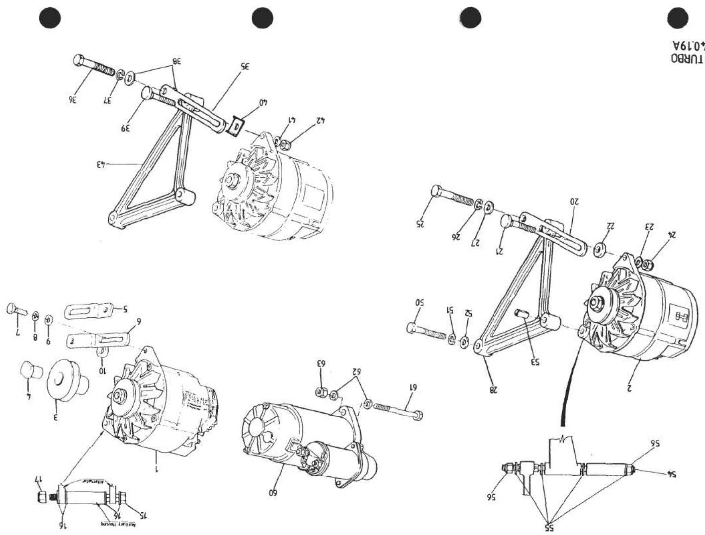
4019A
TURBO
| ILLUSNO. | DESCRIPTION | PART NUMBER | QUANTITY | MAY 1991REMARKS | |
| DRYSUMP | WETSUMP | ||||
| 40.19A | |||||
| Alternator, 70A | A907E6320F | 1 | Discard Pulley Supplied | ||
| 1 | Alternator and Pulley Assy. 70A | A907E6320F | 1 | Without Air Conditioning, Prior '87 M.Y. | |
| 2 | Alternator and Pulley Assy. 70A | B910E6566F | 1 | With Air Conditioning, All '87 M.Y. On | |
| Fan Kit, Alternator | A910E6818S | 1 | |||
| 3 | Pulley, Alternator | B910E1592F | 1 | ||
| 4 | Nut, Special, Pulley to Alternator | A910E1593F | 1 | ||
| 5 | Strap, Alternator Adjusting | A910E1647K | 1 | ||
| Setscrew, MB x 20, Strap to Alternator | A075W1038Z | 1 | |||
| Washer, Spring, Strap to Alternator | A075W4036Z | 1 | |||
| Spacer, Adjusting Strap to Belt Tensioner | A907E1137F | 1 | |||
| 6 | Strap, Alternator Adjusting | A907E1189F | 1 | ) | |
| 7 | Setscrew, MB x 20, Strap to Alternator | A075W1038Z | 1 | ) | |
| 8 | Washer, Spring, Strap to Alternator | A075W4036Z | 1 | ) | |
| 9 | Washer, Flat, Strap to Alternator | A075W4020Z | 1 | )Wet Sump Prior to '87 M.Y. | |
| 10 | Spacer, Adjusting Strap to Belt to Tensioner | A907E1137F | 1 | ) Without A/C | |
| 15 | Bolt, MB x 127, Alternator to Aux. Hsg. | A075W2050Z | 1 | 1 | ) |
| 16 | Washer, Flat, Alternator to Aux. Hsg. | A075W4020Z | 4 | 4 | ) |
| 17 | Nut, Nyloc, M8, Alt. to Aux. Hsg. | A075W3010Z | 1 | 1 | ) |
| 20 | Strap, Alternator Adjusting | A910E1764F | 1 | > | |
| Bolt, Strap to Alternator | A910E1819F | 1 | R/B A910E2226F > | ||
| 21 | Bolt, Strap to Alternator | A910E2226F | 1 | > | |
| 22 | Spacer, Strap to Alternator | A907E1139F | 1 | > | |
| 23 | Washer, Plain, Strap to Alternator | A075W4020Z | 1 | >Prior to '87 M.Y. | |
| 24 | Nut, Nyloc, M8, Strap to Alternator | A075W3010Z | 1 | > With A/C | |
| 25 | Bolt, M10 x 45, Strap to Engine | A075W2053Z | 1 | > | |
| 26 | Washer, Spring, Strap to Engine | A075W4037Z | 1 | > | |
| 27 | Washer, Plain, Strap to Engine | A075W4024Z | 1 | > | |
| 28 | Steady Bracket, Alternator | C910E1761K | 1 | > | |
| 35 | Strap, Alternator Adjusting (Nylon) | A912E2220F | 1 | ) | |
| 36 | Bolt, M10 x 45, Strap/Brkt./Engine | A075W2053Z | 1 | ) | |
| 37 | Washer, Spring, Strap Fixing | A075W4037Z | 1 | )'87 M.Y. on | |
| 38 | Bush, Alternator Strap | A912E2222F | 2 | ) | |
| 39 | Clamp Bolt, Alternator to Strap | A910E2226F | 1 | ) | |
| d5p47 | Turbo 40.19APage 1 | ||||

| ILLUSNO. | DESCRIPTION | PART NUMBER | QUANTITY | MAY 1991REMARKS | |
| DRYSUMP | WETSUMP | ||||
| 40.19A | |||||
| 40 | Clamp Plate, Alternator to Strap | A912E2221F | 1 | ) | |
| 41 | Washer, Flat, Alternator Fixing | A075W4020Z | 1 | )'87 M.Y. on | |
| 42 | Nut, Nyloc, M8, Alternator Fixing | A075W3010Z | 1 | ) | |
| 43 | Steady Bracket, Alternator | D910E1847K | 1 | ) | |
| 50 | Bolt, Steady Brkt. to Water Pump | A075W2039D | 1 | > | |
| 51 | Washer, Spring, Brkt. to Water Pump | A075W4019Z | 1 | >Prior to '87 M.Y. with A/C | |
| 52 | Washer, Flat, Brkt. to Water Pump | A075W4036Z | 1 | >'87 M.Y. on, with & without A/C | |
| 53 | Bush, Split, Steady Bracket | B910E1796F | 1 | > | |
| 54 | Stud, Alternator to Aux. Hsg. | B910E1797Z | 1 | > | |
| 55 | Washer, Flat, Alt. to Aux. Hsg. | A075W4020Z | 4 | > | |
| 56 | Nut, Nyloc, M8, Alt. to Aux. Hsg. | A075W3010Z | 2 | > | |
| 60 | Starter Motor, Lucas 3M100 | B907E6179W | 1 | 1 | R/B A912E6884F |
| Starter Motor, Lucas M80R | A912E6884F | 1 | 1 | ||
| Insulation Sleeve, Unused Terminal | A910E2385F | 1 | 1 | ||
| 61 | Bolt, M10 x 75, Starter to Engine | A075W2059Z | 2 | 2 | Use with Lucas 3M100 S/Motor |
| Bolt, M10 x 80, Starter to Engine | A075W2061Z | 2 | 2 | Use with Lucas M80R S/Motor | |
| 62 | Washer, Starter to Engine | A075W4024Z | 4 | 4 | |
| 63 | Nut, Nyloc, M10, Starter to Engine | A075W3011Z | 2 | 2 | |

| ILLUSNO. | DESCRIPTION |  PART NUMBER PART NUMBER | QUANTITY | MAY 1991REMARKS | |
| STD.ENGINE | H.C.ENGINE | ||||
| 40.21A | |||||
| 001 | Gasket, Exhaust Manifold to Head | A910E0004K | 4 | ||
| Gasket, Exhaust Manifold to Head | A910E2235F | 4 | |||
| 002 | Manifold, Exhaust | C910E1380K | 1 | R/B A910E2155K | |
| Manifold, Exhaust | A910E2155K | 1 | 1 | ||
| 003 | Washer, Flat, Manifold to Head | A075W4020Z | 12 | ||
| Locking Plate, Manifold to Head, Upper | A910E2419F | 2 | |||
| Locking Plate, Manifold to Head, Lower | A910E2420F | 4 | |||
| 004 | Nut, M8, 'Aerotight' Manifold to Head | A075W3022Z | 12 | 12 | |
| Nut, M8, Special | A082S6013F | 4 | 4 | Alternative Top Fixings if Insufficient Clearance for A075W3035Z | |
| 005 | Gasket, Manifold to Adaptor | B910E1390F | 1 | 1 | |
| 006 | Adaptor, Wastegate | C910E1389F | 1 | 4 x M6/2 x M8 Wastegate Fixing R/B E910E1389F | |
| Adaptor, Wastegate | D910E1389F | 1 | 4 x M6/2 x M10 Wastegate Fix R/B E910E1389F | ||
| Adaptor, Wastegate | E910E1389F | 1 | 1 | 2 x M10 Wastegate Fixing | |
| 007 | Bolt, Adaptor to Manifold | A910E6412F | 4 | 4 | |
| 008 | Lockplate, Adaptor/Manifold Bolts | A910E1562F | 2 | 2 | |
| 009 | Bolt, Wastegate Pipe to Adaptor | A910E6414F | 2 | 2 | |
| 010 | Gasket, Wastegate Pipe to Adaptor | A910E1391F | 1 | 1 | |
| Setscrew, Wastegate to Adaptor | A910E1765F | 4 | For 4-Stud Fixing Wastegate. Replaces Studs and Nuts | ||
| Locktab, Wastegate to Adaptor | A910E1672K | 2 | For 4-Stud Fixing Wastegate | ||
| 011 | Stud, M8, Wastegate to Adaptor | C910E6413K | 2 | ||
| Stud, M10, Wastegate to Adaptor | B910E1826F | 2 | 2 | ||
| Reducing Sleeve, 10/8mm, Wastegate to Adaptor | A910E1976F | 2 | Use to Fit M10 Wastegate with M8 Studs | ||
| 012 | Washer, 8mm, Wastegate to Adaptor | A075W4020Z | 2 | ||
| Locking Plate, Wastegate Adaptor | A910E2422F | 2 | 2 | ||
| 013 | Nut, M8, Wastegate to Adaptor | A075W3022Z | 2 | ||
| Nut, M10, 'Aerotight', Wastegate to Adaptor | A079W3071F | 2 | 2 | ||
| Wastegate Assembly, 4 x M6 Stud Fixing | A910E6430F | 1 | R/B E910E6373F with M8 studs and reducing sleeves | ||
| d5p49 | Turbo 40.21APage 1 | ||||

TURBO 4021A


| ILLUSNO. | DESCRIPTION |  PART NUMBER PART NUMBER | QUANTITY | MAY 1991REMARKS | |
| STD.ENGINE | H.C.ENGINE | ||||
| 014 | Wastegate Assembly, 2 x M8 Stud fixing | D910E6373F | 1 | R/B E910E6373F with reducing sleeves | |
| Wastegate Assembly, 2 x M10 Stud fixing | E910E6373F | 1 | |||
| Wastegate Assembly, 2 x M10 Stud fixing | A910E9206F | 1 | |||
| Diaphragm, Wastegate | A910E6571F | 1 | ) | ||
| Gasket, Diaphragm | A910E6575F | 2 | )For wastegate D/E 910E6373F | ||
| Nut, Locking, Valve Stem | A910E6746F | 2 | ) | ||
| Sealing Washer, Diaphragm Clamping | A910E6747F | 2 | ) | ||
| 015 | Gasket, Wastegate to Adaptor | A910E6431F | 1 | 4 x M6 stud fixing | |
| Gasket, Wastegate to Adaptor | B910E6391F | 1 | 2 x M8 stud fixing | ||
| Gasket, Wastegate to Adaptor | C910E6391F | 1 | 1 | 2 x M10 stud fixing | |
| 017 | Elbow, Wastegate to Boost Control Pipe | A910E6461F | 1 | 1 | |
| 018 | Copper Washer, Elbow to Wastegate | A910E6392F | 1 | 1 | |
| 019 | Locknut, Elbow to Wastegate | A910E6462F | 1 | 1 | |
| 020 | Pipe, Boost Control | A910E1674K | 1 | ||
| Pipe, Boost Control | A910E2160F | 1 | |||
| 021 | Elbow, Turbo to Boost Control Pipe | A910E6460F | 1 | 1 | |
| 022 | Olive, Boost Control Pipe | A910E6463F | 2 | 2 | |
| 023 | Sleeve Nut, Boost Control Pipe | A910E6464F | 2 | 2 | |
| 024 | Turbocharger Assembly | C910E6372F | 1 | 1 | |
| 025 | Gasket, Turbo to Wastegate Adaptor | A910E6376H | 1 | 1 | |
| 026 | Bolt, Turbo to Wastegate Adaptor | A910E6415F | 4 | 4 | |
| 027 | Lockplate, Turbo to Wastegate Adaptor | A910E1563F | 2 | 2 | |
| 028 | Stud, Turbo to Exhaust Pipe | B910E1650K | 4 | 4 | |
| 029 | Nut, Exhaust Pipe to Turbo | A075W3072F | 4 | 4 | |
| 030 | Lockplate, Exhaust Pipe to Turbo | A910E1564F | 2 | 2 | |
| 031 | Gasket, Exhaust Pipe to Turbo | A910E1300F | 1 | 1 | |
| Turbo 40.21APage 2 | |||||
| d5p50 | |||||

TURBO 4023A


| ILLUSNO. | DESCRIPTION | PART NUMBER | QUANTITY | MAY 1991REMARKS | |
| DRYSUMP | WETSUMP | ||||
| Compressor, Air Conditioning | A079P6010F | 1 | |||
| Bracket, Compressor to Engine | B910E1581K | 1 | |||
| Screw, Socket Head, Compressor to Bracket | A079W7025F | 2 | |||
| Nut, M10, Compressor to Bracket | A075W3023Z | 2 | |||
| Washer, 10mm, Compressor to Bracket | A075W4024Z | 4 | |||
| Bush, Compressor Rear Fix | A910E1646K | 1 | |||
| Bolt, M6, Compressor Mounting Rear | A075W2030Z | 1 | |||
| Washer, Compressor Mounting Rear | A075W4016Z | 1 | |||
| Nut, M6, Compressor Mounting Rear | A075W3009Z | 1 | |||
| Idler Pulley/Adjuster Bracket | B910E0947J | 1 | |||
| Setscrew, M8, Belt Adjuster | A075W1040Z | 2 | |||
| Washer, 8mm, Plain | A075W4020Z | 1 | |||
| Washer, 8mm, Conical | A907E0688Z | 1 | |||
| Washer, 8mm, Spring | A075W4036Z | 2 | |||
| 001 | Compressor, Air Conditioning | A079P6010F | 1 | ||
| 006 | Spacer, Compressor to Rear Bracket | A907E1136F | 1 | ||
| 007 | Bolt, M10 x 40, Compressor Rear Fixing | A075W2052Z | 1 | ||
| 008 | Washer, Compressor Rear Fixing | A075W4024Z | 2 | ||
| 009 | Nut, M10, Compressor Rear Fixing | A075W3011Z | 1 | ||
| 010 | Bracket, Compressor Front to Block | A907E1233K | 1 | Prior '87 M.Y.'87 M.Y. On | |
| Bracket, Compressor Front to Block | A912E2276F | 1 | |||
| 011 | Bolt, Compressor to Front Bracket | A075W2051Z | 3 | ||
| 012 | Nut, M10, Compressor to Front Bracket | A075W3011Z | 3 | ||
| 013 | Washer, Compressor to Front Bracket | A075W4024Z | 3 | ||
| 014 | Idler Pulley/Adjuster Bracket 27mm offset* | B907E0898J | 1 | Up to engine No 20825Engine No 20826 onwards*Dimension is pulley axis offset from line joining adjuster bracket fixing hole centres | |
| Idler Pulley/Adjuster Bracket 10mm offset* | A910E9049J | 1 | |||
| 018 | Stud , Pulley Bracket/Comp Bracket/MBH | A907E1197F | 1 | ||
| 019 | Washer, Flat, Pulley Bracket Fixing | A075W4020Z | 1 | ||
| 020 | Nut, Nyloc, M8, Pulley Bracket Fixing | A075W3010Z | 1 | ||
| 021 | Bolt, M8, Idler Pulley Adjust | A075W2037Z | 1 | Turbo 40.23A | |
| 022 | Washer, Conical, Adjusting Slot | A907E0688Z | 1 | R/B A079W4019F Page 1 | |
| d5p51 | Washer, Thick, Adjusting Slot | A079W4019F | 1 | ||

TURBO
4023A


| ILLUS NO. | DESCRIPTION | WGKKPART NUMBER | QUANTITY | MAY 1991REMARKS | |
| DRYSUMP | WETSUMP | ||||
| 023 | Washer, Flat, Idler Pulley Adjust | A075W4020Z | 1 | ||
| 024 | Nut, Nyloc, M8, Idler Pulley Adjust | A075W3010Z | 1 | ||
| d6p23 | Turbo40.23APage 2 | ||||

STD

HC
TURBO
40·28A


| ILLUSNO. | DESCRIPTION | PART NUMBER | QUANTITY | REMARKS | |
| STD. | H.C. | ||||
| 40.28A | |||||
| Engine Upper Gasket Set Comprising | B910E0807W | 1 | Replaces Earlier Cork Type | ||
| 1 | Cylinder Head Gasket | B907E0026Z | 1 | ||
| 2 | Inlet Manifold Gasket | A907E0204Z | 1 | ||
| 3 | Diffuser/Plenum Gasket | A910E1474F | 1 | ||
| 4 | Exhaust Manifold Gasket | A910E0004Z | 4 | ||
| 5 | Camshaft Cover Gasket | A912E2040F | 2 | ||
| 6 | Camshaft Cover Screw Washer | A912E6406F | 6 | ||
| 7 | Camshaft Front Oil Seal | B907E6042Z | 2 | ||
| 8 | Camshaft Rear Cover 'O' Ring | A907E6027Z | 2 | ||
| 9 | Camshaft Housing Oil Feed 'O' Ring | A907E6202Z | 2 | ||
| 10 | Carburettor Mounting 'O' Ring | A910E6387F | 8 | ||
| Engine Upper Gasket Set Comprising | A910E9246W | 1 | |||
| 12 | Cylinder Head Gasket | B907E0026Z | 1 | ||
| 13 | Inlet Manifold Gasket | A912E2009F | 1 | ||
| 14 | Diffuser/Plenum Gasket | A910E1474F | 1 | ||
| 15 | Thermostat Housing Gasket | A026E6102Z | 1 | ||
| 16 | Camshaft Cover Gasket | A912E2040F | 2 | ||
| 17 | Camshaft Cover Screw 'O' Ring | A912E6695F | 6 | ||
| 18 | Camshaft Front Oil Seal | B907E6042Z | 2 | ||
| 19 | Camshaft Rear Cover 'O' Ring | A907E6027Z | 2 | ||
| 20 | Camshaft Housing Access Plug 'O' Ring | A912E6694F | 10 | ||
| 21 | Camshaft Housing Oil Feed 'O' Ring | A907E6202Z | 2 | ||
| 22 | Carburettor Mounting 'O' Ring | A907E6027Z | 8 | ||
| For Exhaust Manifold Gaskets, Order 4-OFF A910E2235F Separately if Required | |||||
| d6p28 | Turbo 40.28A | ||||
TURBO
40·28B

| ILLUSNO. | DESCRIPTION | PART NUMBER | QUANTITY | REMARKS | |
| ALL | |||||
| 40.28B | |||||
| 1 | Engine Lower Gasket SetComprising:- | A910E0808W | 1 | Not used on '87 M.Y. | |
| 2 | Front Cover Gasket | A907E0245Z | 1 | ||
| 3 | Water Pump Gasket | A907E0246Z | 1 | ||
| 4 | Oil Gallery Cover Gasket | A907E0438Z | 1 | ||
| 5 | Auxiliary Housing Gasket | C907E0442Z | 1 | ||
| 6 | Oil Pump Gasket | A907E0474Z | 1 | ||
| 7 | Rear Seal Housing Gasket | A907E0671Z | 1 | ||
| 8 | Scavenge Manifold Gasket | A910E1468F | 1 | Dry Sump Engines Only | |
| 9 | Crankshaft Front Oil Seal | B907E6010Z | 1 | ||
| 10 | Crankshaft Rear Oil Seal | A907E0631Z | 1 | ||
| 11 | Oil Pick Up Pipe Olive | A907E0606Z | 1 | Dry Sump Engines Only | |
| 12 | 'O' Ring, Oil Tank Hose to Pump | A910E6526F | 1 | ||
| 13 | 'O' Ring, Turbo Drain to Sump | A910E6491F | 1 | ||
| Gasket, Turbo Drain to Turbo | A910E6375F | 1 | |||
| d5p77 | Turbo 40.28B | ||||
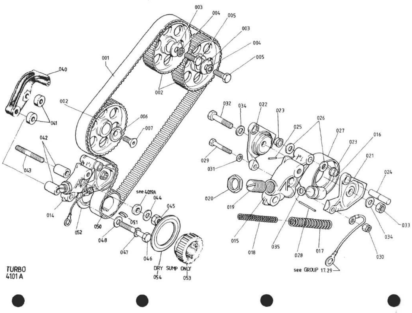
| ILLUS NO. | DESCRIPTION |  PART NUMBER PART NUMBER | QUANTITY | REMARKS | |
| HEATER ONLY | WITH ACU | ||||
| 41.01A | |||||
| 001 | Belt, Camshaft Timing | A907E0191Z | 1 | 1 | Trapezoidal Tooth Profile |
| 002 | Toothed Pulley, Camshaft/Auxiliary Shaft | A910E0309F | 3 | 3 | 104° M.O.P. Green dots |
| 003 | Washer, Pulley to Camshaft | A907E6026Z | 2 | 2 | |
| 004 | Washer, Spring, Pulley to Camshaft | A075W4037Z | 2 | 2 | |
| 005 | Bolt, M10 x 35, Pulley to Camshaft | A075W2051Z | 2 | 2 | |
| 006 | Washer, Pulley to Auxiliary Shaft | A907E0576Z | 1 | 1 | |
| 007 | Screw, M10 x 30 C/S, Pulley to Auxiliary Shaft | A075W7018Z | 1 | 1 | |
| 014 | Tensioner Assembly, Timing Belt | A907E0893K | 1 | Slotted adjuster | |
| Tensioner Assembly, Timing Belt | A907E0913K | 1 | Hex. Head adjuster | ||
| 015 | Housing, Belt Tensioner | B907E1143F | 1 | 1 | |
| 016 | Piston, 'Nylatron' Belt Tensioner | A907E1245F | 1 | 1 | |
| 017 | Spring, Outer, Belt Tensioner | A907E1164F | 1 | 1 | |
| 018 | Spring, Inner, Belt Tensioner | A907E1165F | 1 | 1 | |
| 019 | Seat, Tensioner Spring, Slotted | B907E1146F | 1 | ||
| Seat, Tensioner Spring, Hex. Head | A907E1269F | 1 | |||
| 020 | Locknut, Spring Seat | A907E1149F | 1 | 1 | |
| 021 | Yoke, Front, Belt Tensioner | B907E1141F | 1 | 1 | |
| 022 | Yoke, Rear, Belt Tensioner | B907E1142F | 1 | 1 | |
| 023 | Bush, Pivot, Belt Tensioner | B907E1163F | 2 | 2 | |
| 024 | Pin, Pivot, Belt Tensioner | A907E1144F | 1 | 1 | |
| 025 | Spirol Pin, Pivot Pin Retention | A907E6283F | 1 | 1 | |
| 026 | Rubber Washer, Yoke Pivot | A907E1148F | 1 | 1 | |
| 027 | Pulley/Bearing, Belt Tensioner | A907E6249F | 1 | 1 | |
| 028 | Locking Pin, 4 mm, Tensioner Piston | A907E1195F | 1 | 1 | |
| 029 | Belt, M6 x 30, Yoke Clamping | A075W2028Z | 1 | 1 | |
| 030 | Nut, Nyloc, M6, Yoke Clamping | A907E6285Z | 1 | 1 | |
| 031 | Washer, flat, Yoke Clamping | A075W4013Z | 1 | 1 | |
| 032 | Bolt, M8 x 35, Yoke Centre Clamping | A075W2038W | 1 | 1 | |
| 033 | Nut, M8, Yoke Centre Clamping | A075W3021Z | 1 | 1 | |
| 034 | Washer, Flat, Yoke Centre Clamping | A075W4020Z | 1 | 1 | |
| 035 | Washer, Spring to Piston | A075W4065Z | 1 | 1 | |
| 040 | Snubber, Auxiliary Shaft Pulley | B907E1140F | 1 | 1 | ) If snubber fitted |
| 041 | Spacer, Snubber to Tensioner | A907E1139F | 2 | 2 | ) Turbo (Prior to '87 M.Y.) 41.01A Page 1 |
| d5p52 | |||||
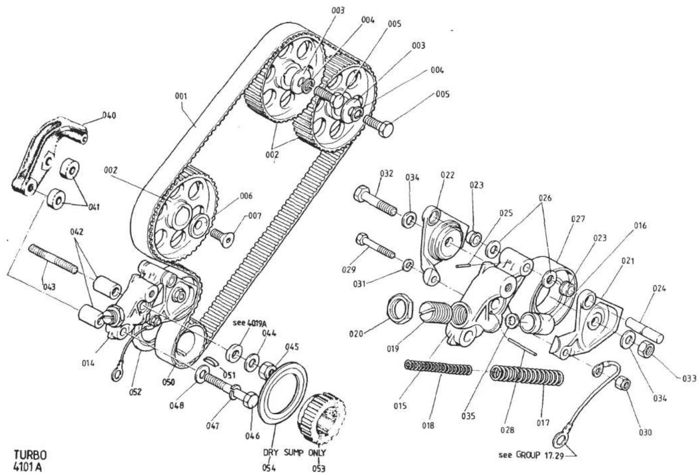


| ILLUS NO. | DESCRIPTION |  PART NUMBER PART NUMBER | QUANTITY | MAY 1991REMARKS | |
| HEATER ONLY | WITH ACU | ||||
| 042 | Spacer, Tensioner to Block | A907E1138F | 2 | 2 | Heater cars with no snubber |
| 043 | Stud, Belt Tensioner to Block | B907E0504K | 1 | ||
| 044 | Washer, Flat, Tensioner Fixing | A075W4024Z | 1 | ||
| 045 | Nut, Nyloc, M10, Tensioner Fixing | A075W3011Z | 1 | ||
| 046 | Bolt, M10 x 70, Tensioner to Block | A075W2058Z | 1 | 2 | |
| 047 | Washer, Spring, Tensioner Fixing | A075W4037Z | 1 | 2 | |
| 048 | Washer, Flat, Tensioner Fixing | A075W4024Z | 1 | 2 | |
| 050 | Toothed Pulley, Crankshaft, Cam Belt Drive | D907E0095Z | 1 | 1 | |
| 051 | Woodruff Key, Crankshaft to Pulley | A907E6016Z | 1 | 1 | |
| 052 | Flange, Crank Pulley Rear | A907E0096Z | 1 | 1 | |
| 053 | Oil Pump, Drive Pulley | A910E1464F | 1 | 1 | ) Dry Sump Only |
| 054 | Flange, Tooth Belt Separation | A910E1466F | 1 | 1 | ) |
| Turbo (Prior to '87 M.Y.) 41.01A Page 2 | |||||
| d5p53 | |||||

TURBO ('87 M.Y. ON)
41.01B


| ILLUS. NO. | DESCRIPTION | PART NUMBER | QUANTITY | REMARKS | |
| 87 M.Y ON | |||||
| 41.01B | |||||
| 1 | Toothed Belt, Camshaft Driving | A912E6697F | 1 | Rounded Tooth Profile (H.T.D.) | |
| 2 | Toothed Pulley, Camshaft/ Aux Shaft | A912E2019F | 3 | Green Dots. 104° M.O.P. | |
| 5 | Washer, Camshaft Pulley Retention | A907E6026Z | 3 | ||
| 6 | Washer, Spring, Cam Pulley Retention | A075W4037Z | 3 | ||
| 7 | Bolt, M10x35, Cam Pulley Retention | A075W2051Z | 3 | ||
| 10 | Bracket, Belt Tensioner to Block | A912E2275F | 1 | )Heater Only Cars | |
| 11 | Bolt, M10x45, Tensioner brkt/Block | A075W2053Z | 2 | )(For A/C Cars see 40.23A) | |
| Washer, Flat, Tensioner brkt Fixing | A075W4024Z | 2 | ) | ||
| 13 | Stud, M10, Tensioner Fixing | B907E0504K | 1 | ||
| 15 | Eccentric Hub, Belt Tensioner | A912E2176F | 1 | ||
| 16 | Pulley/Bearing, Belt Tensioner | A907E6249F | 1 | ||
| 18 | Nut, Nyloc, M10 | A075W3011Z | 1 | ||
| Washer, Plain Tensioner Fix | A075W4024Z | 1 | |||
| 20 | Toothed Pulley, Crankshaft, Cam Belt Drive | A912E2018F | 1 | Rounded Tooth Profile (H.T.D.) | |
| 21 | Flange, Toothed Pulley Rear | A907E0096Z | 1 | ||
| 22 | Woodruff Key, Toothed Pulley | A907E6016Z | 1 | ||

| ILLUS NO. | DESCRIPTION |  PART NUMBER PART NUMBER | QUANTITY | MAY 1991REMARKS | |
| DRYSUMP | WETSUMP | ||||
| 1 | 'V' Belt, Water Pump | A907E6296F | 1 | 1 | Prior to '87 M.Y. |
| 2 | 'V' Belt, Water Pump/Vacuum Pump | A907E6332F | 1 | '87 M.Y. on | |
| 'V' Belt, Alternator | A907E6315F | 1 | |||
| 3 | 'V' Belt, Alternator | A907E6315F | 1 | Prior to '87 M.Y. with Heater Only | |
| 4 | 'V' Belt, Alternator | A907E6332F | 1 | Prior to '87 M.Y. with A/C & '87 M.Y. on | |
| 5 | 'V' Belt, a/c Compressor | A907E6333F | 1 | ||
| 'V' Belt, (Standard Type), a/c Comp. | A907E6333F | 1 | Use With Adj. Brkt. B907E0898) See | ||
| 6 | 'V' Belt, (Moulded Cog), a/c Comp | A910E6656F | 1 | Use With Adj. Brkt. A910E9049) 40.23A | |
| 'V' Pulley, Water Pump | B910E1594K | 1 | |||
| 10 | 'V' Pulley, Water Pump | A907E6294F | 1 | ||
| 11 | Setscrew, M8 x 16, Pulley | A075W1036Z | 4 | ||
| 12 | Washer, Flat, Pulley Fixing | A075W4020Z | 4 | ||
| 13 | Washer, Spring, Pulley Fixing | A075W4036Z | 4 | ||
| 'V' Pulley, Alternator | B910E1592F | 1 | |||
| Nut, Pulley to Alternator | A910E1593F | 1 | |||
| 'V' Pulley, Crankshaft, Triple Groove | A910E1465F | 1 | |||
| 17 | 'V' Pulley, Crankshaft, Triple Groove | A907E1193F | 1 | Except Heater Cars Prior to '87 M.Y. | |
| 18 | 'V' Pulley, Crankshaft, Double Groove | A907E1192F | 1 | Heater Only Prior to '87 M.Y. | |
| Spirol Pin, 'V' Pulley Locating | A907E6007Z | 1 | |||
| 20 | Washer, Conical, Pulley Retention | B907E1106F | 1 | 1 | |
| Washer, Plain, Pulley Retention | A079W4066F | 1 | |||
| Washer, Spring, Pulley Retention | A075W4038Z | 1 | |||
| Bolt 'V' Pulley to Crank | A079W2090F | 1 | |||
| 23 | Setscrew, 1⁄2" UNF x 11⁄2" Pulley/Crank | A075W1020Z | 1 | ||

| ILLUSNO. | DESCRIPTION | PART NUMBER | QUANTITY | MAY 1991 | |
| PRIOR'87 M.Y | '87 M.YON | REMARKS | |||
| 42.01A | |||||
| 001 | Plenum, RH Air Scoop | A082B4291K | 1 | 1 | |
| Screw, Plenum to Body | A075W5015Z | 4 | 4 | ||
| Spire Nut, Plenum | A075W6013Z | 4 | 4 | ||
| 002 | Adaptor, Plenum to Hose | A079B4131K | 1 | 1 | |
| Pop Rivet, Adaptor to Plenum | A075W6094Z | 4 | 4 | ||
| 003 | Trunking, Plenum to Airbox | A082E4081F | 1 | 1 | |
| 004 | Hose Clip, Trunking | A907E6347F | 2 | 2 | |
| 005 | Airbox | A082E4084K | 1 | 1 | |
| Insulation, Airbox | A907E1424K | 1 | |||
| Foam Strip, Airbox to Body | A036B6221V | lm | lm | ||
| 007 | Spire Bolt, Airbox to Body | A079W6166F | 4 | 4 | |
| 008 | Spire Nut, Airbox to Body | A079W6164F | 4 | 4 | |
| 010 | Cover, Airbox | A082E4085K | 1 | 1 | |
| 011 | Adaptor Pipe, Breather to Airbox | B082E4086F | 1 | 1 | Not Used on Earlier Cars |
| 014 | Clamp, Airbox Cover to Body, Upper | C082E4080K | 2 | 2 | |
| Clamp, Airbox Cover to Body, Lower | A082U4939F | 2 | 2 | ||
| 015 | Setscrew, M6 x 30, Cover to Body | A075W1032Z | 4 | 4 | |
| 016 | Washer, Spring, Cover to Body | A075W4035Z | 4 | 4 | |
| 017 | Washer, Flat, Cover to Body | A075W4013Z | 4 | 4 | |
| 018 | Nut, 'Pulsert' M6, Cover to Body | A079W6156F | 4 | 4 | |
| 021 | Trunking, Airbox to Turbo | A910E1089F | 1 | Used With Turbo Inlet Adaptor Sleeve | |
| Trunking, Airbox to Turbo | E907E1089F | 1 | 1 | Cars Without Turbo Inlet Adaptor Sleeve | |
| 022 | Hose Clip, Trunking to Airbox | A036S6006Z | 1 | 1 | |
| 023 | Hose Clip, Trunking to Turbo/Sleeve | A075L6044F | 1 | 1 | |
| 024 | Adaptor Sleeve, Turbo Inlet | C910E1710F | 1 | )Where Fitted | |
| 024A | Seal, Adaptor Sleeve to Turbo | C910E1712F | 1 | ) | |
| 025 | Plenum Backplate, Carburettor | B910E1472K | 1 | ||
| Plenum Backplate, Carburettor | A910E1880K | 1 | |||
| 026 | Gasket, Diffuser to Backplate | A910E1474F | 1 | 1 | |
| 027 | Gasket, Plenum Cover to Backplate | A910E1475F | 1 | 1 | |
| 028 | Plenum Chamber Cover, Carburettor | C910E1471K | 1 | ||
| Plenum Chamber Cover, Carburettor | D910E1471K | 1 | |||
| 030 | Dump Valve Assembly | C910E0928J | 1 | ||
| 031 | Gasket, Dump Valve Plenum | A910E1499F | 1 | ||
| 037 | Bolt, M6 x 55, Dump Valve to Plenum | A075W2034Z | 2 | Turbo 42.01A | |
| d5p55 | Page 1 | ||||
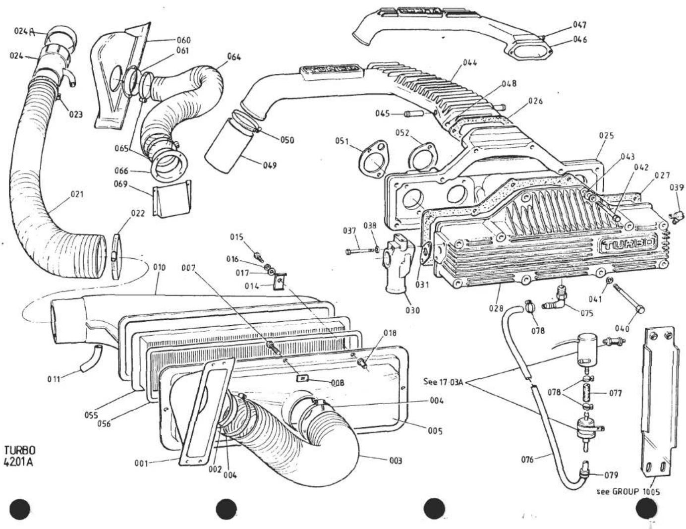
| ILLUS NO. | DESCRIPTION |  PART NUMBER PART NUMBER | QUANTITY |  REMARKS REMARKS | |
| PRIOR'87 M.Y | '87 M.Y ON | ||||
| 038 | Washer, Flat, Dump Valve to Plenum | A075W4013Z | 2 | ||
| 039 | Elbow Union, Boost Gauge, Screw-on Pipe Fit. | A910E6481F* | 1 | Prior to A910E2274 | |
| Elbow Union, Boost Gauge, Screw-on Pipe Fit. | A910E2274K* | 1 | |||
| Grub Screw, Elbow Union, Damping | A082W7034F | 1 | Fits A910E2274* R/B Elbow Union A910E6772. Cut off end fitting from boost pipe & fit connecting hose A082N4020 with restrictor A912E6452 | ||
| Elbow Union, Boost Gauge, Push-on Pipe Fit. | A910E6772F | 1 | |||
| Elbow Union, Engine Management Take-Off | A910E6772F | 1 | |||
| 040 | Bolt, Plenum Cover to Backplate | A075W2045F | 8 | 8 | |
| 041 | Washer, Flat, Cover to Backplate | A075W4020Z | 8 | 8 | |
| 042 | Bolt, Plenum Cover/Backplate/Diffuser | A075W2042Z | 2 | 2 | |
| 043 | Washer, Flat, Cover/Backplate/Diffuser | A075W4020Z | 2 | 2 | |
| 044 | Diffuser, Turbo to Plenum | A910E0949J | 1 | ||
| 045 | Stub Pipe, Cold Start Take Off | A910E1600F | 2 | ||
| 046 | Diffuser, Turbo to Plenum (inc. Stub Pipe) | A910E9230F | 1 | ||
| 047 | Stub Pipe, Cold Start Take-Off | A910E2125F | 1 | ||
| 048 | Helicoil Insert | A910E6510F | 2 | 2 | |
| 049 | Hose, Turbo to Diffuser | D910E6394F | 1 | ||
| Hose, Turbo to Diffuser | A910E1912F | 1 | |||
| 050 | Clip, Turbo/diffuser Hose | A910E6389F | 2 | 2 | |
| 051 | Gasket, Plenum Backplate to Carb. | A910E1536F | 2 | ||
| Gasket, Plenum Backplate to Carb. | A910E1886F | 2 | |||
| 052 | Gasket, Plenum Backplate to Carb. | A910E1537F | 2 | ||
| Gasket, Plenum Backplate to Carb. | A910E1887F | 2 | |||
| 055 | Air Filter Element | A907E6182F | 1 | 1 | |
| 056 | Seal, Filter Element | C907E0588F | 1 | 1 | |
| 060 | Plenum, LH Air Scoop | B082B4599K | 1 | ||
| 061 | Adaptor, Plenum to Hose | A079B4130K | 1 | ||
| Pop Rivet, Adaptor to Plenum | A075W6095Z | 3 | |||
| Washer, Adaptor to Plenum | A075W4013Z | 6 | |||
| 064 | Trunking, Adaptor to Sidewall | A082E4140F | 1 | ||
| 065 | Hose Clip, Trunking | A036S6006Z | 2 | ||
| 066 | Adaptor, Angled | A082B4568K | 1 | ||
| Pop Rivet, Adaptor to Sidewall | A075W6095F | 4 | Turbo 42.01APage 2 | ||
| d5p56 | |||||
REMARKS

| ILLUS NO. | DESCRIPTION |  PART NUMBER PART NUMBER | QUANTITY | REMARKS | |
| PRIOR '87 M.Y | '87 M.Y ON | ||||
| 42.01A | |||||
| 069 | Washer, M6 x 12, Adaptor to Sidewall | A075W4013Z | 8 | ||
| Air Deflector, Engine Sidewall | B082U5074K | 1 | |||
| Pop Rivet, Deflector Fix | A075W6095F | 4 | |||
| Washer, Deflector Fix | A075W4013Z | 8 | |||
| 075 | Elbow Adaptor, Plenum Purge | A910E6765F | 1 | ||
| 076 | Pipe, Purge, Elbow/Solenoid Valve | A910E2325K | 1 | ||
| 077 | Pipe, Purge, Solenoid Valve/Purge Pump | A910E2326K | 1 | ||
| Pipe, Purge, Purge Pump Exhaust | A910E2327K | 1 | |||
| 078 | Clip, 'Norma', 12-20mm, Pipe Fix | A079M6132F | 5 | ||
| 079 | Grommet, Purge Pump/Sidewall | X036J6026Z | 1 | ||
| d5p78 | Turbo 42.01APage 3 | ||||

| ILLUSNO. | DESCRIPTION |  PART NUMBER PART NUMBER | QUANTITY | MAY 1991REMARKS | |
| PRIOR'87 M.Y | '87 M.YON | ||||
| 42.03A | |||||
| 005 | Carburettor, Rear, DHLA 40H | B910E0925F | 1 | ||
| 006 | Carburettor, Front, DHLA 40H | B910E0926F | 1 | ||
| Carburettor, Rear, DHLA 45M | A910E6856F | 1 | |||
| Carburettor, Front, DHLA 45M | A910E6855F | 1 | |||
| Throttle Lever | A910E1394F | 1 | For Hairpin Type Return Spring | ||
| 010 | Throttle Lever | B910E1394F | 1 | For Coil Type Return Spring | |
| Throttle Lever | A907E6086Z | 1 | |||
| Spring, Throttle Return | A074E0464F | 1 | Hairpin Type | ||
| 011 | Spring, Throttle Return | A082J6072F | 1 | Coil Type | |
| 012 | Split Pin, Coil Spring to Lever | A082W6262F | 1 | ||
| 013 | Anchor Bracket, Coil Spring to Cam Cover | A082J4123F | 1 | ||
| 014 | Screw, Anchor Brkt. to Cam Cover | A079W7011F | 2 | 2 | |
| Spring, Throttle Return | A910E6865F | 1 | |||
| Bracket, Spring to Plenum | A910E2308F | 1 | |||
| Setscrew, Spring Brkt. to Plenum | A075W1027Z | 2 | |||
| Spring Washer, Brkt. to Plenum | A075W4035Z | 2 | |||
| 016 | Linkage Assembly, Cold Start Interconnect | A910E0986J | 1 | ||
| Linkage Assembly, Cold Start Interconnect | A910E9231K | 1 | |||
| 017 | Screw, Drilled, Cable to Lever | A036E6146Z | 1 | > | |
| 018 | Screw, Link to Lever | A036E6143Z | 1 | > | |
| 019 | Pivot Bush, Choke Linkage | A910E6532F | 2 | >inc. in Linkage Assy. | |
| Pivot Bush, Choke Linkage | A910E2302F | 2 | > | ||
| 020 | Washer, Flat | A036E6145Z | 1 | > | |
| 021 | Washer, Spring | A036E6045Z | 1 | > | |
| 026 | Bell Mouth, Carb. Intake | A910E6539H | 4 | ||
| Bell Mouth, Carb. Intake | A907E6090H | 4 | |||
| Pipe, Steel Braided, PRV to Front Carb. | A910E0962F | 1 | ) | ||
| Pipe, Steel Braided, PRV to Rear Carb. | A910E0963F | 1 | ) | ||
| Adaptor, Fuel Pipe to Carb. | A910E1657F | 2 | ) With Steel Braided Fuel Pipes | ||
| Filter, Carb. Fuel Inlet | A910E6528F | 2 | ) | ||
| Washer, Sealing, Adaptor to Carb. | A910E6527F | 2 | ) | ||
| d5p57 | Turbo 42.03APage 1 | ||||
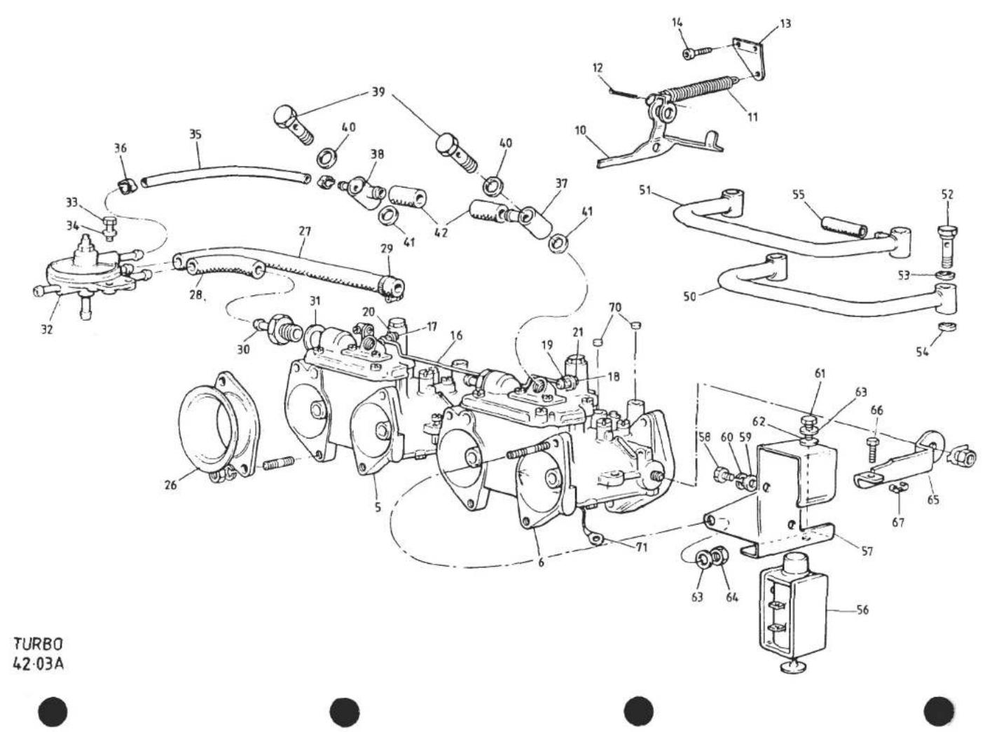
| ILLUS NO. | DESCRIPTION |  PART NUMBER PART NUMBER | QUANTITY | MAY 1991REMARKS | |
| PRIOR'87 M.Y | 1987M.Y.ON | ||||
| 42.03A | |||||
| 062 | Washer, M6, Brkt. Fix | A075W4013Z | 1 | ||
| 063 | Washer, M6, Internal Spring, Brkt. Fix | A075W4046Z | 2 | ||
| 064 | Nut, M6, Brkt. Fix | A075W3020Z | 1 | ||
| 065 | Lever, Throttle Spindle | A910E1872F | 1 | ||
| 066 | Adjusting Screw, Lever to Solenoid | A910E6617F | 1 | ||
| Clip, Adjuster Screw Locking | A910E6618F | 1 | |||
| 070 | Plug, Anti-Tamper, CO & Air Bleed | A907E1227F | 8 | Nylon | |
| Plug, Anti-Tamper, CO & Throttle Coupling | A907E1227F | 4 | Metal | ||
| Plug, Anti-Tamper, Air Bleed | A910E6654F | 4 | |||
| 071 | Earth Lead, Carburettor/Engine | A082M4208F | 2 | 2 | |
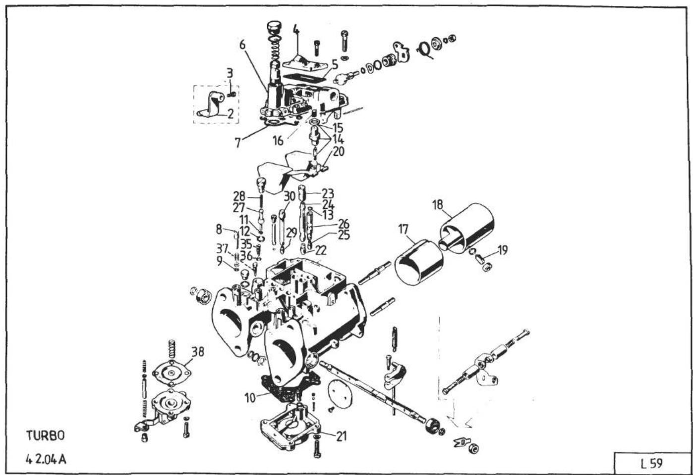
L59
| ILLUS NO. | DESCRIPTION |  PART NUMBER PART NUMBER | QUANTITY | MAY 1991REMARKS | |
| PRIOR'87 M.Y | '87 M.YON | ||||
| 42.03A | |||||
| 027 | Pipe, Dunlop, PRV to Front Carb. | A910E1957K | 1 | Cut From A910E6650V > With Dunlop | |
| 028 | Pipe, Dunlop, PRV to Rear Carb. | A910E1958K | 1 | Cut From A910E6650V > Fuel Pipes | |
| 029 | Hose Clip, Dunlop Fuel Pipes | A079M6132F | 4 | > | |
| 030 | Adaptor, Fuel Pipe to Carb. | A910E1959F | 2 | > | |
| 031 | Washer, Sealing, Adaptor to Carb. | A910E6651F | 2 | > | |
| 032 | Fuel Pressure Regulating Valve(8.5mm S/Spigot) | A910E1607F | 1 | R/B A910E6615F + 180mm of A910E6785V | |
| Fuel Pressure Regulating Valve(5.0mm S/Spigot) | A910E6615F | 1 | |||
| Cap, Anti-Tamper, PRV | A910E1956F | 1 | |||
| 033 | Setscrew, PRV Fixing | A075W1028Z | 2 | 2 | |
| 034 | Washer, Spring, PRV Fixing | A075W4035Z | 2 | 2 | |
| 035 | Hose, Pressure Sensing | A910E1606F | 1 | Use with PRV A910E1607F>PRV to Rear Carb. | |
| Hose, Pressure Sensing | A910E6785V | 180mm | Use with PRV A910E6615F> | ||
| 036 | Clip, Oetiker, Pressure Sensing Hose | A910E6479F | 2 | ||
| 037 | Banjo, Front Carb. | A910E1602K | 1 | )Cold Start Air Supply | |
| 038 | Banjo, Rear Carb. | A910E1603K | 1 | ) | |
| 039 | Bolt, Banjo | A910E1601K | 2 | ||
| 040 | Washer, Banjo, Large | A079W4081F | 2 | ||
| 041 | Washer, Banjo, Small | A079W4082F | 2 | ||
| 042 | Hose, Cold Start, Banjo to Diffuser | A910E1605F | 2 | ||
| 050 | Pipe, Carburettor Balance | A910E9039F | 1 | ||
| 051 | Pipe, Cold Start Air Supply, Diffuser/Carbs. | A910E9229F | 1 | ||
| 052 | Bolt, Banjo, Balance/Pipe Cold Start Air Pipes | A910E1601K | 4 | ||
| 053 | Washer, Banjo, Large | A079W4081F | 4 | ||
| 054 | Washer, Banjo, Small | A079W4082F | 4 | ||
| 055 | Hose, Cold Start, Banjo to Diffuser | A910E1605F | 1 | ||
| 056 | Solenoid, Throttle Jacking | B910E9030J | 1 | ||
| 057 | Bracket, Solenoid to Carb. | A912E2231F | 1 | ||
| 058 | Setscrew, M4 x 6, Solenoid Fix | A075W1087F | 2 | ||
| 059 | Washer, Solenoid Fix | A079W4073F | 2 | ||
| 060 | Washer, Spring, Solenoid Fix | A075W4088F | 2 | ||
| 061 | Setscrew, M6 x 30, Brkt. to Carb. | A075W1032Z | 1 | ||
| d5p58 | Turbo 42.03APage 2 | ||||

| ILLUSNO. | DESCRIPTION |  PART NUMBER PART NUMBER | QUANTITY | MAY 1991REMARKS | |
| PRIOR'87 M.Y | '87 M.YON | ||||
| 42.04A | |||||
| 23 | Air Corrector Jet, Main, 200 | A910E6485H | 4 | Quantities are per car | |
| Air Corrector Jet, Main, 180 | A910E6873F | 4 | |||
| 24 | Emulsion Tube, Main, 12 | A910E6486H | 4 | ||
| Emulsion Tube, Main, 14 | A910E6875F | 4 | |||
| 25 | Idle Jet, 40 | A910E6603F | 4 | ||
| Idle Jet, 58 | A912E6452H | 4 | |||
| Idle Air Tube | A907E6268F | 4 | |||
| Idle Air Tube | A912E6647H | 4 | |||
| 27 | Pump Jet, 48H Special | A910E6488H | 4 | ||
| Pump Jet, 35 | A910E6877F | 4 | |||
| 28 | Filter, Pump Jet | A910E6686F | 4 | 4 | If Fitted |
| 29 | Starter Jet, 80 | A912E6449H | 2 | 2 | |
| 30 | Emulsion Tube, Starter | A907E6188H | 2 | 2 | |
| 35 | Air Bleed Screw | A910E6775F | 4 | 4 | |
| 36 | 'O' Ring, Air Bleed Screw | A910E6776F | 4 | 4 | |
| 37 | Plug, Vacuum Tapping Orifice | A910E6777F | 4 | 4 | |
| 38 | Accelerator Pump Diaphragm | A907E6309F | 2 | ||
| Accelerator Pump Diaphragm | A910E6852F | 2 | |||
| Adaptor, eng. man. & Spring Anchor | A910E6881F | 2 | |||
| d5p76 | Turbo 42.04APage 2 | ||||

| ILLUS NO. | DESCRIPTION |  PART NUMBER PART NUMBER | QUANTITY |  REMARKS REMARKS | |
| PRIOR '87 M.Y | '87 M.Y ON | ||||
| 42.04A | |||||
| 2 | Abutment, Choke Cable | A036E6064Z | 1 | 1 | Quantities are per car |
| 3 | Screw, Cable to Abutment | A074K6002Z | 1 | 1 | |
| 4 | Jet Cover, Cold Start Air Intake | A910E6672F | 2 | ||
| Jet Cover, Cold Start Air Intake | A910E6880F | 2 | |||
| 5 | Gasket, Jet Cover | A910E6834F | 2 | Red 0.7mm ) | |
| Gasket, Jet Cover | A910E6673F | 2 | Black 0.4mm ) | ||
| Gasket, Jet Cover | B910E6834Z | 2 | 2 | Red 0.6mm | |
| 6 | Top Cover | A910E6671F | 2 | ||
| 7 | Gasket, Top Cover, (Float Chamber) | A910E6835F | 2 | Red 0.7mm >R/B B910E6835Z | |
| Gasket, Top Cover, (Float Chamber) | A910E6689F | 2 | Black 0.4mm >R/B B910E6835Z | ||
| Gasket, Top Cover, (Float Chamber) | B910E6835Z | 2 | 2 | Red 0.6mm | |
| 8 | Screw, Idle CO Adjust | A910E6600F | 4 | 4 | |
| 9 | 'O' Ring, Idle CO Screw | A036E6096Z | 4 | 4 | |
| 10 | Gasket, Pump Body | A910E6676F | 2 | 2 | |
| 11 | 'O' Ring, Small, Pump Jet | A036E6100Z | 4 | 4 | |
| 12 | 'O' Ring, Large, Pump Jet | A036E6101Z | 4 | 4 | |
| 13 | 'O' Ring, Idle Emulsion Tube | A036E6107Z | 4 | 4 | |
| 14 | Needle Valve. Float, 200 | A910E6677F | 2 | 2 | |
| 15 | Gasket, Needle Valve | A036E6070Z | 2 | 2 | |
| 16 | Filter, Needle Valve | A910E6678F | 2 | 2 | If Fitted |
| Gasket Kit (All Gaskets & Seals for 2 Carbs.) | A910E6599F | 1 | R/B B910E6599F | ||
| Gasket Kit (All Gaskets & Seals for 2 Carbs.) | B910E6599F | 1 | 1 | Inc. in addition Naturally Aspirated Type Jet Cover Gaskets (Brown) | |
| 17 | Choke, 36mm | A910E6487H | 4 | ||
| Choke, 35mm | A907E6273F | 4 | |||
| 18 | Auxiliary Venturi | A910E1637H | 4 | ||
| Auxiliary Venturi | A910E6882F | 4 | |||
| 19 | Screw, Auxiliary Venturi Retaining | A910E6601F | 4 | 4 | |
| 20 | Float Assembly, 8.5g | A911E6444H | 2 | 2 | |
| 21 | Accelerator Pump Body, 27 | A910E6602F | 2 | 2 | |
| 22 | Main Jet, 185 | A910E6484F | 4 | ||
| Main Jet, 160 | A907E6277H | 4 | |||
| d5p59 | Turbo 42.04APage 1 | ||||
REMARKS
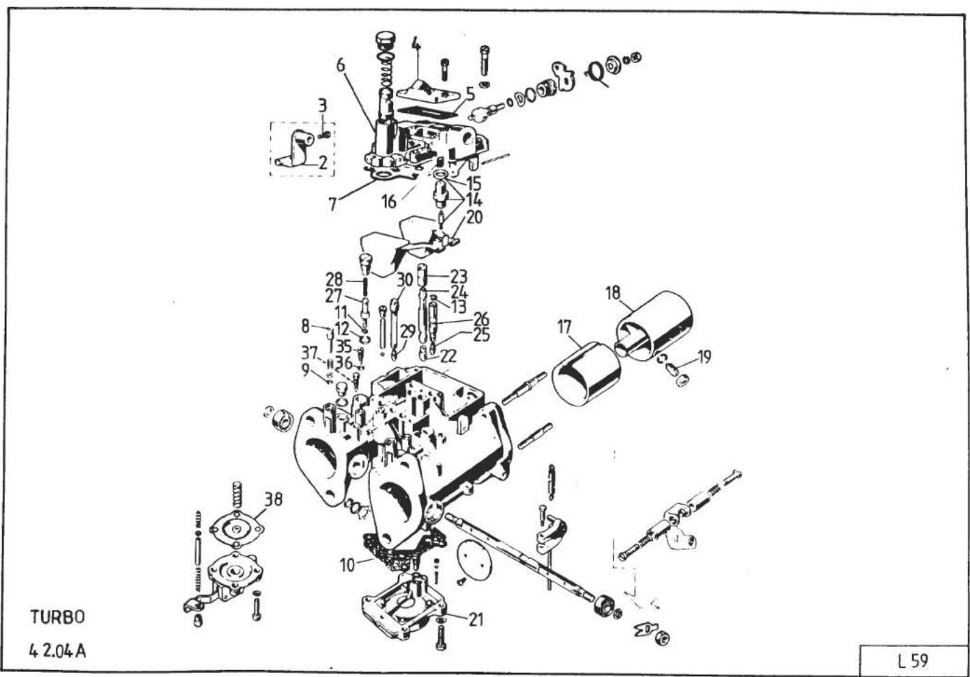


| ILLUSNO. | DESCRIPTION | PART NUMBER | QUANTITY | MAY 1991REMARKS | |
| PRIOR'87 M.Y | '87 M.YON | ||||
| 42.07A | |||||
| 001 | Inlet Manifold | C910E1523K | 1 | ||
| 003 | Gasket, Inlet Manifold to Head | A907E0204Z | 1 | ||
| 004 | Stud, Manifold to Carburettors | D910E1478K | 8 | ||
| 008 | Water Rail | E910E1397K | 1 | R/B B910E1818K | |
| Water Rail | B910E1818K | 1 | |||
| 009 | Hose, Manifold to Water Rail | A910E1635F | 3 | ||
| 010 | Hose Clip, Manifold/Water Rail Hose | A079K6018F | 6 | ||
| 013 | Elbow Hose, Cylinder Head to Water Rail | B910E1399F | 1 | ||
| 014 | Hose Clip, Elbow Hose | A079K6018F | 2 | ||
| 017 | Stub Pipe, Manifold Water Outlet | A907E0486Z | 3 | ||
| 018 | Nut, Manifold to Head | A075W3021Z | 9 | ||
| 019 | Washer, Manifold to Head | A075W4020Z | 9 | ||
| 020 | Spacer, Manifold to Carburettors | A910E1636K | 4 | ||
| 021 | 'O' Ring, Manifold/Spacer/Carb. | A910E6387F | 8 | ||
| 022 | Nut, Carb. to Manifold | A075W3010Z | 8 | ||
| 023 | Cup Washer, Carb. to Manifold | C036E0471Z | 16 | ||
| 024 | Rubber Washer, Carb. to Manifold | B036E0470Z | 8 | ||
| 030 | Connector Union, Manifold Vacuum | B910E1398F | 4 | ) Up to VIN 82 D 1954) 82 - 0576) | |
| 031 | Hose, Manifold to Vacuum Rail | B910E1504F | 4 | ||
| 032 | Hose, Clip, Connector Hose | A082L6042F | 8 | ||
| 033 | Vacuum Rail, Balance Pipe | A910E1664K | 1 | ||
| 034 | Connector Union, Vac. Rail | A026E0367Z | 2 | ||
| 035 | Connector Union, Manifold Vacuum | A089P6000F | 2 | >From VIN 82 D 1955> 82 - 0577 | |
| 036 | Blanking Plug, Manifold Tract 3 & 4 | A907E6023F | 2 | ||
| d5p60 | Turbo (Prior '87 M.Y.)42.07A | ||||
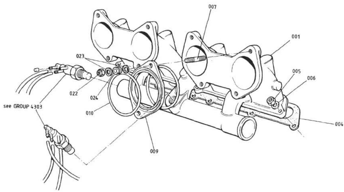
TURBO ('87 M.Y. ON)
4207B


1
| ILLUSNO. | DESCRIPTION | PART NUMBER | QUANTITY | MAY 1991REMARKS | |
| 1987M.Y.ON | |||||
| 42.07B | |||||
| 001 | Inlet Manifold | A912E2184K | 1 | ||
| 004 | Gasket, Inlet Manifold to Head | A912E2009F | 1 | ||
| 005 | Nut, Manifold to Head | A075W3021Z | 9 | ||
| 006 | Washer, Manifold to Head | A075W4020Z | 9 | ||
| 007 | Stud, Manifold to Carburettors | D910E1478K | 8 | ||
| 009 | Spacer, Manifold to Carburettors | B907E0129Z | 4 | ||
| 010 | 'O' Ring, Manifold/Spacer/Carb. | A907E6027Z | 8 | ||
| 022 | Nut, Carb. to Manifold | A075W3010Z | 8 | ||
| 023 | Cup Washer, Carb. to Manifold | C036E0471Z | 16 | ||
| 024 | Rubber Washer, Carb. to Manifold | B036E0470Z | 8 | ||
| d5p79 | Turbo ('87 M.Y. ON) 42.07B | ||||

| ILLUS NO. | DESCRIPTION |  PART NUMBER PART NUMBER | QUANTITY | REMARKS | |
| '87 M.Y ON | |||||
| 001 | Thermal Ignition Valve (T.I.V.) | A912E6796F | 1 | Light Green, R/B A910E6893F | |
| Thermal Ignition Valve (T.I.V.) | A910E6893F | 1 | Green | ||
| 002 | Hose, Vacuum, (T.I.V.) to Ign.Solenoid Valve | A910E2313K | 1 | Black/Red. (900mm of A910E6783F) | |
| Grommet, Engine Bay Sidewall | X036J0026Z | 1 | |||
| 003 | Hose, Vacuum, (T.I.V.) to Throttle Edge Port | B912E2224K | 1 | Black/White. (350mm of A910E6784F) | |
| 004 | Hose, Vacuum, (T.I.V.) to Distributor | A912E2223K | 1 | Black. (260mm of A910E6786F) | |
| 004A | Restrictor, Pulsation Damping | A912E6452H | 1 | ||
| 005 | Crankcase Breather Valve (C.B.V.) | A912E6802F | 1 | ||
| 006 | Adaptor, Crankcase Breather Valve | A912E6806F | 1 | ||
| 007 | Cold Enrichment Thermal Valve (C.E.T.V.) | A910E6792F | 1 | R/B B910E6792F | |
| Cold Enrichment Thermal Valve (C.E.T.V.) | B910E6792F | 1 | Brown | ||
| 008 | Cap, Rubber, Blanking (C.E.T.V.) | A912E6804F | 1 | ||
| 010 | Hose, Vacuum, (C.B.V.) to (C.E.T.V.) | A910E2322K | 1 | Black. (200mm of A910E6786F) | |
| 011 | Hose, Vacuum, (C.E.T.V.) to Non Return Valve | A910E2316K | 1 | Black/White. (45mm of A910E6784F) | |
| 012 | Non Return Valve | A910E6863F | 1 | ||
| 013 | Hose, Vacuum, Non Return Valve to T-Piece | A910E2315K | 1 | Black/White. (85mm of A910E6784F) | |
| 015 | T-Piece | A082J6089F | 1 | ||
| 016 | Hose, Vacuum, T-Piece to Overboost Switch | A910E2314K | 1 | Black/White. (700mm of A910E6784F) | |
| 017 | Overboost Switch | A082M4610Z | 1 | ||
| 018 | Hose, Vacuum, Junction Connecting | A910E2323K | 1 | Black. (90mm of A910E6786F) | |
| 019 | T-Piece, Rear Carburettor Connection | A082J6089F | 1 | ||
| 020 | Hose, Vacuum, Rear Carb. to T-Piece | A912E2240K | 1 | ||
| 022 | Pipe, Connecting, 1/4" OD, Carburettor | A912E2238K | 1 | ||
| 023 | Elbow, Connecting Pipe to Carburettor | A912E6805F | 1 | ||
| 024 | Clip, Elbow Pipe | A079M6132F | 1 | ||
| 025 | Connector, 4-Way | A910E6645F | 1 | ||
| 026 | Hose, Vacuum, 4-Way to Distributor | A910E2318K | 1 | Black/Blue. (350mm of A910E6785F) | |
| 027 | Hose, Vacuum, 4-Way to Pressure Reg. Valve | A910E2319K | 1 | Black/Blue. (180mm of A910E6785F) | |
| 028 | Hose, Vacuum, 4-Way to Plenum Adaptor | A910E2317K | 1 | Black/Blue. (40mm of A910E6785F) | |
| 030 | Hose, Vacuum, 4-Way to T-Piece | A910E2320K | 1 | Black/Blue. (400mm of A910E6785F) | |
| 031 | T-Piece | A082J6089F | 1 | ||
| 032 | Hose, Vacuum, T-Piece to Ign. Solenoid Valve | A910E2321K | 1 | Black/Blue. (200mm of A910E6785F) | |
| 033 | Ignition Solenoid Valve (I.S.V.) | A910E6764F | 1 | ||
| d6p24 | Turbo ('87 M.Y. On) 43.03APage 1 | ||||
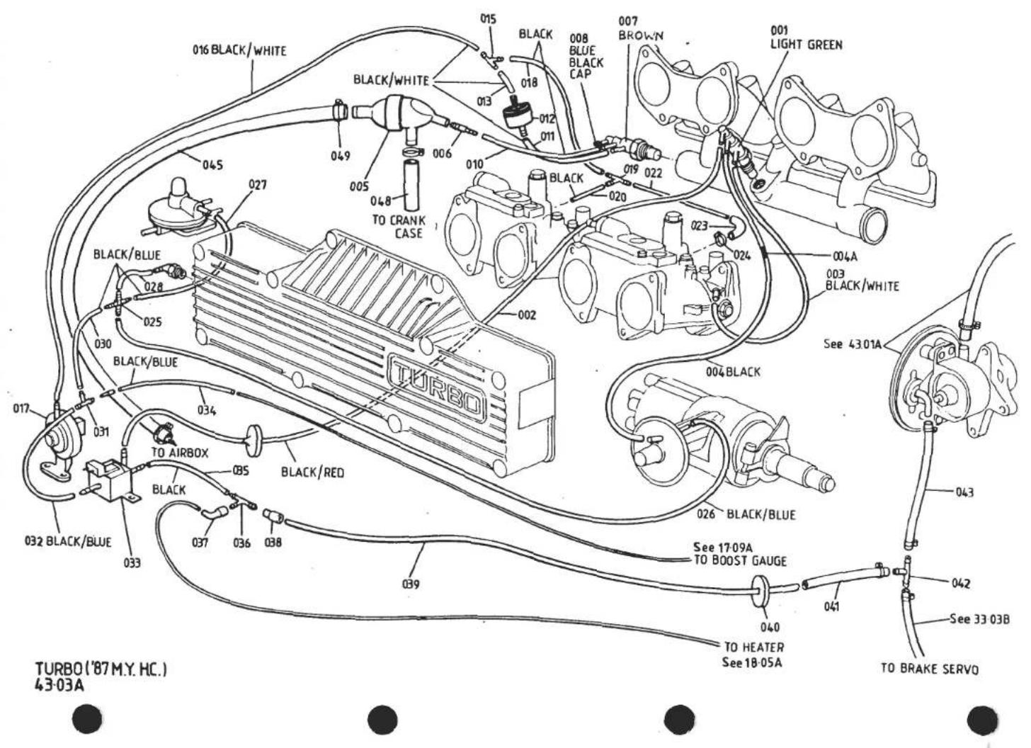
| ILLUS NO. | DESCRIPTION |  PART NUMBER PART NUMBER | QUANTITY | MAY 1991REMARKS | |
| '87 M.Y ON | |||||
| 034 | Hose, Vacuum, (I.S.V.) to Boost Gauge Pipe | A910E2320K | 1 | Black/Blue, (400mm of A910E6785F) | |
| 035 | Hose, Vacuum, (I.S.V.) to T-Piece | A910E2324K | 1 | Black, (100mm of A910E6786F) | |
| 036 | T-Piece | A082J6089F | 1 | ||
| 037 | Elbow, Heater/A/C Take-Off | A075P6069F | 1 | ||
| 038 | Connector Sleeve, T-Piece/Vacuum Supply Pipes | A075P6080F | 1 | ||
| 039 | Pipe, Vacuum Supply | B082J4162K | 1 | ||
| 040 | Grommet, Engine Bay Sidewall, Boost/Vac.Pipes | X036J6026Z | 1 | ||
| 041 | Connector, Hose | A082J4164K | 1 | ||
| 042 | T-Piece, Hose Connector | A082L6048F | 1 | ||
| 043 | Hose Vacuum, T-Piece to Vacuum Pump | A075J6078V | 1 | 340mm length | |
| 045 | Pipe, (C.B.V.) to Airbox | A910E2309F | 1 | ||
| 048 | Hose, (C.B.V.) to Crankcase | B912E2236F | 1 | ||
| 049 | Clip, Hose, (C.B.V.) Hoses | A907E6805F | 4 | ||

| ILLUS NO. | DESCRIPTION |  PART NUMBER PART NUMBER | QUANTITY | MAY 1991REMARKS | |
| ALL | |||||
| 002 | Filler Cap Assembly, Lockable | B076L0167F | 2 | ||
| Filler Cap Cover | A076L0168K | 2 | |||
| Filler Cap Shutter | A076L6003F | 2 | |||
| Filler Cap Base, (Inc. Lock & Keys) | A082L4137F | 2 | |||
| 006 | Clamp Ring, Filler Neck | A079L4034F | 2 | ||
| 007 | Gasket, Clamp Ring to Body | A079L4035F | 2 | ||
| 008 | Screw, No. 6 x 1⁄2" Clamp Ring | A075W5014F | 8 | ||
| 009 | Fuel Filler Neck, LH | C082L4049F | 1 | )6.5mm Breather Hose Spigot | |
| 010 | Fuel Filler Neck, RH | C082L4050F | 1 | ) | |
| Fuel Filler Neck, LH | D082L4049F | 1 | >8.0mm Breather Hose Spigot | ||
| Fuel Filler Neck, RH | D082L4050F | 1 | > | ||
| 025 | Hose, Filler Neck to Tank | A082L4112F | 2 | ||
| 026 | Hose Clip, Filler Hose | A075L6044F | 4 | ||
| 027 | Pipe, Filler Vent | A082L4071F | 2 | ||
| 028 | Hose Clip, Filler Vent Hose | A079K6018F | 4 | ||
| 029 | Fuel Tank, LH (Requires Banjo Offtake) | C082L4045F | 1 | R/B E082L4045F | |
| Fuel Tank, LH (Integral Fuel Pipe Spigot) | E082L4045F | 1 | |||
| 030 | Fuel Tank, RH (Requires Banjo Offtake) | C082L4046F | 1 | R/B E082L4046F | |
| Fuel Tank, RH (Integral Fuel Pipe Spigot) | E082L4046F | 1 | |||
| 031 | Grommet, Crossover Hose/Body | A082L4064F | 2 | ||
| 032 | Ring, Grommet Fixing | A082L4065K | 2 | ||
| Screw, Ring Fixing | A075W5034Z | 8 | )R/B 033 & 034 | ||
| Spire Nut, Ring Fixing | A075W6016Z | 8 | ) | ||
| 033 | Screw, Ring Fixing | A075W5016Z | 8 | ||
| 034 | Washer, Ring Fixing | A075W4000Z | 8 | ||
| 035 | Foam, Tank Clamping | A082L4063F | 2 | ||
| 036 | Foam, Tank Seating | A079L4032K | 2 | ||
| Pad, Self Adhesive, Noise Damping | A082V7167K | 17 | Tank Side & LH Top) | ||
| Pad, Self Adhesive, Noise Damping | A082V7168K | 2 | Tank Top )If | ||
| Pad, Self Adhesive, Noise Damping | A082V7169K | 1 | RH Tank Top )Fitted | ||
| Pad, Self Adhesive, Noise Damping | A082V7170K | 2 | Tank Bottom ) | ||
| 043 | Setscrew, M8 x 20, Tank to Body | A075W1038Z | 2 | ||
| 044 | Washer, Flat,M8 x 25, Tank to Body | A075W4021Z | 4 | ||
| 045 | Washer, Spring, Tank to Body | A075W4036Z | 2 | ||
| d5p61 | Turbo 44.01APage 1 | ||||

| ILLUS NO. | DESCRIPTION |  | QUANTITY | MAY 1901 | |
| PART NUMBER | ALL | REMARKS | |||
| 44.01A | |||||
| 047 | Pipe, Crossover | B082L4061F | 1 | ||
| 048 | Hose, Clip, Crossover Pipe Hoses | A075M6145F | 4 | ||
| 049 | Hose, Moulded, Tank to Crossover Pipe | B082L4062F | 2 | ||
| 050 | Grommet, Crossover Pipe/Chassis | A046K6001F | 2 | ||
| Sender Unit, Fuel Gauge | A082L4051F | 1 | R/B A082L6032F | ||
| 051 | Sender Unit, Fuel Gauge | A082L6032F | 1 | Inc. Gasket | |
| Gasket, Sender Unit | A026L6000F | 1 | |||
| 052 | Screw, 10 UNF x 1", Sender Fixing | A075W1002F | 6 | ) | |
| Washer, Spring, Sender Fixing | A075W4030F | 6 | )R/B A082W7044F | ||
| Washer, Flat, Sender Fixing | A075W4011F | 6 | ) | ||
| Capscrew, 10 UNF x 1", Sender Fix | A082W7044F | 6 | |||
| 055 | Washer, Fibre, Sender Fixing | A075W4058F | 6 | ||
| 056 | Board, Fuel Tank Top, LH | A082U4673F | 1 | ||
| 057 | Board, Fuel Tank Top, RH | A082U4674F | 1 | ||
| 058 | Bracket, Tank Board to Bulkhead | A082U4675K | 2 | ||
| 060 | Bracket, Tank Board to Wheelarch | A082U4676K | 2 | ||
| 062 | Studplate, Bracket to Bulkhead | A082U4677K | 2 | ||
| 064 | Washer Plate, Bulkhead Brkt./Board | A082U4678K | 2 | ||
| 065 | Washer Plate, Wheelarch Brkt./Board | A082U4679K | 2 | ||
| 066 | Washer Plate, Wheelarch Brkt/Body | A082U4680K | 2 | ||
| 068 | Setscrew, M8 x 20, Wheelarch Brkt. | A075W1038Z | 8 | ||
| 069 | Nut, Nyloc, M8, Bulkhead Brkt. | A075W3010Z | 8 | ||
| Turbo 44.01A | |||||
| Page 2 | |||||
| d5p62 | |||||
TURBO 44.03A
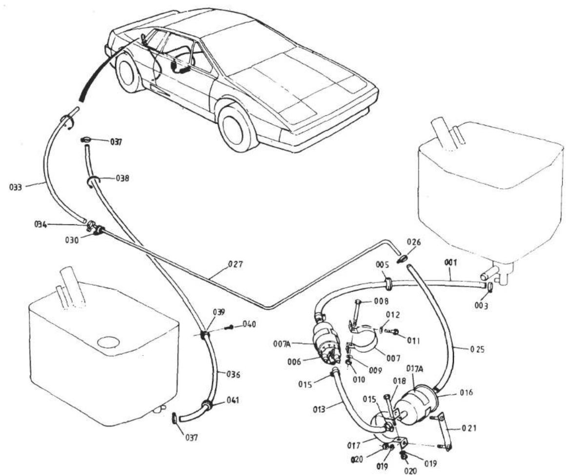


| ILLUS NO. | DESCRIPTION |  PART NUMBER PART NUMBER | QUANTITY | MAY 1991REMARKS | |
| ALL | |||||
| 44.03A | |||||
| 001 | Banjo, 10mm, LH Tank Fuel FeedBanjo, 12mm, LH Tank Fuel FeedCopper Washer, BanjoCrush Washer, 1⁄2", BanjoBolt, BanjoPipe, Steel Braided, LH Tank to PumpPipe, Dunlop, LH Tank to PumpPipe, Dunlop, LH Tank to PumpClip, Fuel Pipe to Tank and PumpClip, Fuel Pipe to Tank and PumpGrommet, Pipe Thro' BodyFuel PumpClamp, Fuel Pump Mtg.Insulator Strip, Clamp to PumpBolt, M5 x 40, Pump ClampingWasher, Plain, Pump ClampingNut, Nyloc, M5, Pump ClampingSetscrew, M6 x 20, Clamp to ChassisWasher, Flat, Clamp to ChassisRubber Bobbin, Pump Brkt. to BodyNut, 5/16" UNF, Bobbin to Pump Brkt.Nut, Nyloc, 5/16" UNF, Bobbin to BodyTapping Plate, Pump Bracket to BodyPop Rivet, Tapping Plate to BodyWasher, Flat, Bobbin FixWasher, Spring, Bobbin to Pump Brkt. | A082L6027FA082L4103FA079L6006FA075L6022FA079L6005FA082L4065KA082L4098KB082L4098KA079M6132FA082L6042FA075L6025FA082L6014FB082L4067FA075L0112ZA079W2033FA075W4011FA075W3008ZA075W1030ZA075W4013ZX050S0156ZA075W3040ZA075W3002ZA082L4121FA075W6094FA075W4020ZA075W4036ZA082L4057KA082L4123HA910E6479FA075W6228FA075W5020FA082L6016FA082L4066FA082L4092F | 1111111111111111111111111111111111111111111111111111111111111111111111111111111111111111111111111111 | ) )If Fitted ) )Cut From A082L6017V (400mm)Cut From A082L6038V (400mm)*Cut From A082L6038V (520mm)†For Steel Braided PipeFor Dunlop Pipe*) ) >R/B A082L4121F >>†> | * with pump mounted on chassis† with pump mounted on bodyTurbo 44.03APage 1 |
| 003 | |||||
| 005 | |||||
| 006 | |||||
| 007 | |||||
| 007A | |||||
| 008 | |||||
| 009 | |||||
| 010 | |||||
| 011 | |||||
| 012 | |||||
| 013 | Pipe, Pump to FilterPipe, Pump to FilterClip, Oetiker, 9/16''P' Clip, Open, Pump to Filter HoseScrew, 'P' Clip FixingFilter, FuelClamp, Fuel FilterInsulator Strip, Clamp to Filter | ||||
| 015 | |||||
| 016 | |||||
| 017 | |||||
| 017A | |||||
| d5p63 | |||||
TURBO
44.03A


| ILLUSNO. | DESCRIPTION |  PART NUMBER PART NUMBER | QUANTITY | MAY 1931REMARKS | |
| ALL | |||||
| 44.03A | |||||
| 001 | Banjo, 10mm, LH Tank Fuel Feed | A082L6027F | 1 | ) | |
| Banjo, 12mm, LH Tank Fuel Feed | A082L4103F | 1 | ) | ||
| Copper Washer, Banjo | A079L6006F | 1 | )If Fitted | ||
| Crush Washer, 1", Banjo | A075L6022F | 1 | ) | ||
| Bolt, Banjo | A079L6005F | 1 | ) | ||
| Pipe, Steel Braided, LH Tank to Pump | A082L4065K | 1 | Cut From A082L6017V (400mm) | ||
| Pipe, Dunlop, LH Tank to Pump | A082L4098K | 1 | Cut From A082L6038V (400mm)* | ||
| Pipe, Dunlop, LH Tank to Pump | B082L4098K | 1 | Cut From A082L6038V (520mm)† | ||
| Clip, Fuel Pipe to Tank and Pump | A079M6132F | 2 | For Steel Braided Pipe | ||
| 003 | Clip, Fuel Pipe to Tank and Pump | A082L6042F | 2 | For Dunlop Pipe | |
| 005 | Grommet, Pipe Thro' Body | A075L6025F | 1 | ||
| 006 | Fuel Pump | A082L6014F | 1 | ||
| 007 | Clamp, Fuel Pump Mtg. | B082L4067F | 1 | ||
| 007A | Insulator Strip, Clamp to Pump | A075L0112Z | 1 | ||
| 008 | Bolt, M5 x 40, Pump Clamping | A079W2033F | 1 | ||
| 009 | Washer, Plain, Pump Clamping | A075W4011F | 2 | ||
| 010 | Nut, Nyloc, M5, Pump Clamping | A075W3008Z | 1 | ||
| 011 | Setscrew, M6 x 20, Clamp to Chassis | A075W1030Z | 2 | )* | |
| 012 | Washer, Flat, Clamp to Chassis | A075W4013Z | 2 | ) | |
| Rubber Bobbin, Pump Brkt. to Body | X050S0156Z | 2 | > | ||
| Nut, 5/16" UNF, Bobbin to Pump Brkt. | A075W3040Z | 2 | > | ||
| Nut, Nyloc, 5/16" UNF, Bobbin to Body | A075W3002Z | 2 | R/B A082L4121F > | ||
| Tapping Plate, Pump Bracket to Body | A082L4121F | 1 | >† | ||
| Pop Rivet, Tapping Plate to Body | A075W6094F | 1 | > | ||
| Washer, Flat, Bobbin Fix | A075W4020Z | 2/4 | > | ||
| Washer, Spring, Bobbin to Pump Brkt. | A075W4036Z | 2 | > | ||
| 013 | Pipe, Pump to Filter | A082L4057K | 1 | Cut From A075L6043V (300mm)* | |
| Pipe, Pump to Filter | A082L4123H | 1 | Cut From A075L6043V (410mm)† | ||
| 015 | Clip, Oetiker, 9/16" | A910E6479F | 2 | ||
| 'P' Clip, Open, Pump to Filter Hose | A075W6228F | 2 | >† | ||
| Screw, 'P' Clip Fixing | A075W5020F | 2 | > * with pump mounted on chassis | ||
| 016 | Filter, Fuel | A082L6016F | 1 | † with pump mounted on body | |
| 017 | Clamp, Fuel Filter | A082L4066F | 1 | ||
| 017A | Insulator Strip, Clamp to Filter | A082L4092F | 1 | ||
| d5p63 | Turbo 44.03APage 1 | ||||
TURBO 44.03A


| ILLUS NO. | DESCRIPTION |  PART NUMBER PART NUMBER | QUANTITY | MAY 1991REMARKS | |
| ALL | |||||
| 44.03A | |||||
| 018 | Bolt, M6 x 60, Filter Clamping | A082W2078F | 1 | ||
| 019 | Washer, Flat, Filter Clamp | A075W4013Z | 4 | ||
| 020 | Nut, Nyloc, M6, Filter Clamp | A075W3009Z | 3 | ||
| 021 | Studplate, Filter Clamp to Body | A082L4068K | 1 | ||
| 025 | Pipe, Filter to Bundy | A082L4097K | 1 | Cut From A075L6043V (350mm)* | |
| Pipe, Filter to Bundy | A082L4124H | 1 | Cut From A075L6043V (200mm)† | ||
| 026 | Clip, Oetiker, 9/16" | A910E6479F | 2 | ||
| 027 | Bundy Pipe, Fuel Feed | A082L4054F | 1 | ||
| 030 | 'P' Clip, Bundy Fixing | A075Q6013F | 4 | ||
| Screw, s/t, P Clip Fix | A075W5033Z | 3 | |||
| Spire Nut, P Clip Fix | A075W6011Z | 3 | |||
| Pipe, Steel Braided, Bundy to P.R.V. | B082L4069J | 1 | |||
| 033 | Pipe, Dunlop, Bundy to P.R.V. | A082L4101K | 1 | Cut From A082L6036V (500mm) | |
| 034 | Clip, Pipe to Bundy & P.R.V. | A082L6042F | 2 | For Dunlop Pipe | |
| Pipe, Steel Braided, P.R.V. to RH Tank | B082L4070J | 1 | |||
| 036 | Pipe, Dunlop P.R.V. to RH Tank | A082L4102K | 1 | Cut From A910E6650V (1450mm) | |
| 037 | Clip, Pipe to P.R.V. and Tank | A082L6042F | 2 | For Dunlop Pipe | |
| 038 | Tie Wrap, Return Hose to Chassis | A075W6038Z | 1 | ||
| 039 | 'P' Clip, Return Hose to Body | A075W6002Z | 2 | ||
| 040 | Screw, s/t, 'P' Clip Fixing | A075W5016Z | 2 | ||
| 041 | Grommet, Return Hose/Body | A075L6025F | 1 | ||
| Banjo, RH Tank | A082L4072F | 1 | ) | ||
| Copper Washer, Banjo | A079L6006F | 1 | )If Fitted | ||
| Crush Washer, ‡", Banjo | A075L6022F | 1 | ) | ||
| Bolt, Banjo | A079L6005F | 1 | ) | ||
| * With pump mounted on chassis† With pump mounted on body | |||||
| Turbo 44.03APage 2 | |||||
| d5p64 | |||||

TURBO 44.05A


| ILLUSNO. | DESCRIPTION | PART NUMBER | QUANTITY | MAY 1031 | |
| ALL | REMARKS | ||||
| 44.05A | |||||
| 1 | Breather Hose, Filler Neck to Anti Surge Valve | A085L4078K | 2 | 5.7mm I/D. Use with 6.5mm Filler Neck Spigot | |
| Breather Hose, Filler Neck to Anti Surge Valve | A082L4125F | 2 | 7.1mm I/D. Use with 8mm Filler Neck Spigot | ||
| 2 | Clip, Breather Hose to Filler Neck | A075U6082F | 2 | ||
| 3 | Clip, Breather Hose to Valve | A079W6189F | 2 | ||
| 4 | Valve, Anti Surge | B076L6001F | 2 | ||
| 5 | 'P' Clip, Valve Fixing | A075W6000Z | 2 | ||
| 6 | 'P' Clip, Valve Fixing | A075W6002Z | 2 | ||
| Pop Rivet | A075W6092Z | 2 | |||
| Washer | A075W4001Z | 2 | |||
| 9 | Breather Hose, 200 mm, Anti Surge to 'T' Piece | A085L4079K | 1 | ||
| 10 | Breather Hose, 2 m, Anti Surge to 'T' Piece | A085L4080K | 1 | ||
| 11 | 'T' Piece, Breather Hose | A075L6042F | 1 | ||
| 12 | Breather Hose, 3.2 m | A085L4081K | 1 | ||
| 13 | Clip, Hose to 'T' & Valves | A075L6018F | 5 | ||
| 14 | 'P' Clip, Breather Hose Fixing | A075W6021Z | 4 | ||
| Pop Rivet Breather Hose Fixing | A075W6090Z | 4 | |||
| Washer, Breather Hose Fixing | A075W4062Z | 4 | |||
| d5p73 | Turbo 44.05A | ||||

TURBO 4503A


| ILLUSNO. | DESCRIPTION |  PART NUMBER PART NUMBER | QUANTITY | MAY 1991REMARKS | |
| ALL | |||||
| 45.03A | |||||
| 1 | Exhaust Pipe, Main | A082S4082F | 1 | ||
| 3 | Exhaust Pipe, Wastegate | A082S4081F | 1 | ||
| 4 | Bolt, Pipes to Silencer | A075W2038D | 6 | ||
| 5 | Nut, Pipes to Silencer | A075W3035Z | 6 | ||
| 6 | Silencer & Tail Pipes | A082S4083F | 1 | R/B B082S4105F'84 M.Y. On | |
| Silencer & Tail Pipes | B082S4105F | 1 | |||
| 7 | Clamp, Silencer to Channel | A079S4066F | 2 | ||
| 8 | Setscrew, M8, Silencer Clamp | A075W1043Z | 2 | ||
| 9 | Nut, M8, Silencer Clamp | A075W3035Z | 2 | ||
| 10 | Channel, Silencer Mounting | A079S4065S | 1 | ||
| 11 | Nut, M10, Channel to Bracket | A075W3011Z | 2 | ||
| 12 | Washer, Channel to Bracket | A075W4027Z | 2 | ||
| Bracket, Silencer Mounting | A079S4061F | 1 | Prior to C35 G/Box | ||
| 13 | Bracket, Silencer Mounting | C082S4096F | 1 | With C35 G/Box R/B D082S4126F & Fixings | |
| Bracket, Silencer Mounting | D082S4126F | 1 | |||
| 14 | Stud, Bracket to Gearbox | A079F4030F | 1 | R/B B079F4030F | |
| Stud, M7 x 128, Bracket to Gearbox | B079F4030F | 1 | Used with bracket D082S4126F | ||
| Nut, Nyloc, M7, Bracket to Gearbox | A079F6023F | 1 | |||
| Washer, Flat, Bracket to Gearbox | A075W4002Z | 1 | |||
| 15 | Bolt, Bracket to Gearbox | A079F4031F | 1 | >R/B B079F4031F | |
| 16 | Bolt, Bracket to Gearbox | A079F4031F | 2 | With C35 G/Box > | |
| Bolt, M7 x 50, Bracket to Gearbox | B079F4031F | 3 | Used with Bracket D082S4126F | ||
| Turbo 45.03A | |||||
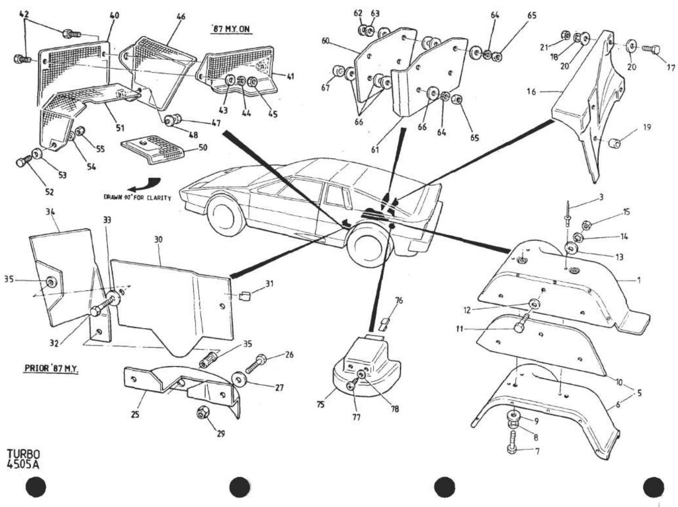
| ILLUSNO. | DESCRIPTION |  PART NUMBER PART NUMBER | QUANTITY | REMARKS | |
| PRIOR'87 M.Y | '87 M.YON | ||||
| 45.05A | |||||
| 1 | Heatshield, Body & Tyre, (Aluminium) | B082B4283K | 1 | 1 | 2 Pieces, Inc. Jacknuts |
| Jacknut, M6, Heatshield | A075W3031Z | 4 | 4 | ||
| Screw, S/T, Alum. Shield Joining | A075W5012Z | 6 | 6 | ||
| 3 | Pop Rivet, 3/16", Shield to Body | B075W6089Z | 7 | 7 | |
| Washer, Pop Rivet | A075W4002Z | 7 | 7 | ||
| 5 | Heatshield Assy. Body & Tyre (Ferrobestos) | D082B4284F | 1 | 1 | Comprises Items 6 and 10 |
| 6 | Heatshield, Body, (Ferrobestos) | A082D4343H | 1 | 1 | |
| 7 | Setscrew, M6 x 12, (Ferro.) Shield Fix | A075W1027Z | 4 | 4 | |
| 8 | Washer, Shakeproof, (Ferro.) Shield Fix | A075W4046Z | 4 | 4 | |
| 9 | Washer, Large O/D, (Ferro.) Shield Fix | A075W4017Z | 4 | 4 | |
| 10 | Heatshield, Tyre, (Ferrobestos) | A082B4344H | 1 | 1 | |
| 11 | Setscrew, M6 x 16, (Ferro.) Shield Fix | A075W1028Z | 3 | 3 | |
| 12 | Washer, Flat, (Ferro.) Shield Fix | A075W4013Z | 3 | 3 | |
| 13 | Washer, Large O/D, (Ferro.) Shield Fix | A075W4017Z | 6 | 6 | |
| 14 | Washer, S/Proof, (Ferro.) Shield Fix | A075W4046Z | 3 | 3 | |
| 15 | Nut, Nyloc, M6, (Ferro.) Shield Fix | A075W3009Z | 3 | 3 | |
| 16 | Heatshield, Engine Bay Rear | A082B4303F | 1 | 1 | |
| 17 | Screw, M4 x 10, Heatshield Fix | A075W5079F | 3 | 3 | |
| 18 | Washer, Shakeproof " " | A075W4043Z | 3 | 3 | |
| 19 | Spacer, Insulating " " | A082B6058F | 3 | 3 | |
| 20 | Washer, Flat " " | A075W4000F | 3 | 3 | |
| 21 | Nut, Nyloc " " | A075W3049F | 3 | 3 | |
| 25 | Heatshield, LH Engine Mounting | C082E4092F | 1 | ||
| 26 | Setscrew, M6 x 20, Shield to Chassis | A075W1030F | 2 | ||
| 27 | Washer, Large O/D, " " " | A075W4017F | 2 | ||
| Washer, Flat, " " " | A075W4013F | 2 | |||
| 29 | Nut, Nyloc, M6 " " " | A075W3009F | 2 | ||
| 30 | Heatshield, LH Radius Arm Mtg. | C082E4091F | 1 | ||
| 31 | Clip, Shield to Chassis | A079W6188F | 3 | ||
| 32 | Setscrew, M6 x 20, Shield to Chassis | A075W1030F | 1 | ||
| 33 | Washer, Flat, Shield to Chassis | A075W4013F | 1 | ||
| 34 | Heatshield, Compressor/A/C Pipes | C082P4207F | 1 | ||
| 35 | Jacknut, Heatshield Fix | A075W3031F | 2 | ||
| Setscrew, M6 x 20, Heatshield Fix | A075W1030F | 1 | |||
| Washer, Large O/D, Heatshield Fix | A075W4017F | 1 | Turbo 45.05APage 1 | ||
| d5p66 | |||||

| ILLUS NO. | DESCRIPTION |  PART NUMBER PART NUMBER | QUANTITY | MAY 1991REMARKS | |
| PRIOR'87 M.Y | '87 M.YON | ||||
| 45.05A | |||||
| 40 | Heatshield, Radius Arm Mounting | A082E4150F | 1 | ||
| Setscrew, M6 x 20, Heatshield Fix | A075W1031F | 1 | |||
| 41 | Heatshield | A082E4146F | 1 | ||
| 42 | Setscrew, M6 x 20, Heatshield Fix | A075W1030F | 3 | ||
| 43 | Washer, Flat, M6 x 15, Heatshield Fix | A075W4015Z | 3 | ||
| 44 | Washer, Spring, M6, Heatshield Fix | A075W4035Z | 3 | ||
| 45 | Nut, M6, Heatshield Fix | A075W3020Z | 3 | ||
| 46 | Heatshield, Vacuum Pump | A082E4149F | 1 | ||
| 47 | Setscrew, M6 x 20, Heatshield Fix | A075W1030F | 1 | ||
| 48 | Washer, Flat, M6 x 15, Heatshield Fix | A075W4015Z | 1 | ||
| 50 | Heatshield, Engine Mounting Cover | A082E4147F | 1 | ||
| 51 | Heatshield, Engine Mounting | A082E4148F | 1 | ||
| 52 | Setscrew, M6 x 16, Heatshield Fix | A075W1028F | 1 | ||
| 53 | Washer, Flat, Heatshield Fix | A075W4015Z | 1 | ||
| 54 | Washer, M6 x 12, Heatshield Fix | A075W4013Z | 1 | ||
| 55 | Nut, Nyloc, M6, Heatshield Fix | A075W3009Z | 1 | ||
| Heatshield, Turbo | A910E1402F | 1 | |||
| 60 | Heatshield, Turbo | A910E2172F | 1 | ||
| 61 | Reflector, Turbo Heatshield | A910E2173F | 1 | ||
| 62 | Washer, Flat, M6 x 15, 'Shield/Diffuser Brkt. | A075W4015Z | 2 | ||
| 63 | Washer, Flat, M6 x 15, " " " " | A075W4014Z | 2 | ||
| 64 | Washer, Spring | A075W4035Z | 4 | ||
| 65 | Nut, M6 | A075W3020Z | 4 | ||
| 66 | Washer, Load Spreader | A075W4017Z | 8 | 16 | |
| 67 | Spacer, Heatshield | A907E0696Z | 4 | 2 | |
| 68 | Bolt, M6 x 30, Heatshield/Cover/Housing | A075W2028Z | 4 | ||
| 69 | Washer, Spring | A075W4035Z | 4 | ||
| 75 | Heatshield, LH Damper Top | A082U4764F | 1 | 1 | |
| 76 | Clip, Heatshield to Chassis | A075W6050Z | 1 | 1 | |
| 77 | Screw, Shield Fixing | A075W5038F | 2 | 2 | |
| 78 | Washer, Flat, Shield Fixing | A075W4011F | 2 | 2 | |
| Turbo 45.05APage 2 | |||||
| d5p67 | |||||

| ILLUS NO. | DESCRIPTION |  PART NUMBER PART NUMBER | QUANTITY | MAY 1991REMARKS | |
| ALL | |||||
| 46.01A | |||||
| 001 | Radiator Duct | A082B4237K | 1 | Used With 306mm Support Stays | |
| Radiator Duct | A082B4491K | 1 | With 266 / 286mm Stays.252mm Oil Cooler | ||
| Radiator Duct | B082B4491K | 1 | 325mm Oil Cooler Union Centres | ||
| Radiator Duct | C082B4491K | 1 | Fettle to Fit Rad: A082K4237F | ||
| 002 | Setscrew, M6 x 25, Duct to Body | A075W1031Z | 6 | ||
| 003 | Washer, Large O/D, Duct to Body | A075W4017Z | 12 | ||
| 004 | Nut, Nyloc, M6, Duct to Body | A075W3009Z | 6 | ||
| 005 | Screw, s/t, Duct to Body | A075W5028Z | 3 | ||
| 006 | Spire Nut, Duct to Body | A075W6013Z | 3 | ||
| Support Stay, Radiator Duct | B082K4105K | 2 | )R/B A082K4188/9 | ||
| 'L' Bracket, Stay to Chassis | B082A4166F | 2 | )Ref. S. Bulletin 1983/11 | ||
| Support Stay, Rad. Duct, RH | A082K4188K | 1 | >306mm Between Hole Centres | ||
| Support Stay, Rad. Duct, LH | A082K4189K | 1 | > | ||
| Support Stay, Rad. Duct, RH | A082K4186K | 1 | )266mm Between Hole Centres | ||
| Support Stay, Rad. Duct, LH | A082K4185K | 1 | ) | ||
| 007 | Support Stay, Rad. Duct. RH | A082K4198K | 1 | >286mm Between Hole Centres | |
| 008 | Support Stay, Rad. Duct. LH | A082K4199K | 1 | >1985 Model Year On. | |
| 009 | Setscrew, M6 x 20, Stay to Chassis | A075W1030Z | 2 | ||
| 010 | Washer, Flat, Stay to Chassis | A075W4013Z | 2 | ||
| 011 | Nut, Nyloc, M6, Stay to Chassis | A075W3009Z | 2 | ||
| Spacer Washer, Stay to Chassis | A075W4016Z | 4 | ) | ||
| Setscrew, M6 x 20, Stay to Duct | A075W1030Z | 2 | ) | ||
| Washer, Large O/D, Stay to Duct | A075W4017Z | 2 | )Use With 266 & 286mm Stays | ||
| Washer, Flat, Stay to Duct | A075W4013Z | 2 | ) | ||
| Nut, Nyloc, M6, Stay to Duct | A075W3009Z | 2 | ) | ||
| 012 | Radiator | B082K4101K | 1 | R/B A082K4237F | |
| Radiator | A082K4237F | 1 | |||
| Foam, Radiator top to Body | A079K4001F | 1 | Thick | ||
| Foam, Radiator bottom to Duct | A089K0131F | 1 | Thin | ||
| 013 | Drain Plug, Radiator | B075K6011F | 1 | ||
| 014 | Setscrew, M6 x 25, Radiator to Duct | A075W1031Z | 4 | ||
| Washer, S/Proof, Rad. to Duct | A075W4046Z | 4 | |||
| 015 | Washer, Large O/D, Rad. to Duct | A075W4017Z | 4 | ||
| d5p68 | Turbo (Prior '87 M.Y.) 46.01APage 1 | ||||

| ILLUS NO. | DESCRIPTION |  PART NUMBER PART NUMBER | QUANTITY | REMARKS | |
| ALL | |||||
| 46.01A | |||||
| Washer Bush, Rad. to Duct | AX75B2259F | 8 | )If Fitted | ||
| Jacknut, M6, Rad. to Duct | A075W3034Z | 2 | ) | ||
| 018 | Cowl, Radiator Fans, ABS | D082K4102K | 1 | > | |
| Cowl, Radiator Fans | E082K4102K | 1 | >Fettle to fit A082K4237F | ||
| 019 | Edge Clip, Cowl to Radiator | A079W6187F | 18 | ||
| Fan Shroud & Motor Mounting | C079K4085F | 3 | Use With Metal Fans | ||
| 020 | Fan Shroud & Motor Mounting | A079K4174F | 3 | Use With Plastic Fans | |
| Fan Motor, Rad. Cooling (for metal fan) | A074M6027Z | 3 | )R/B A082K6025F | ||
| Fan, Radiator Cooling, Metal | A074K6000Z | 3 | )See S. Bulletin 1983/21 | ||
| 021 | Fan Motor and Blade Assy. (plastic fan) | A082K6025F | 3 | R/B next four items | |
| Fan Motor, Rad. Cooling (for plastic fan) | A082K6026H | 3 | |||
| Fan, Radiator, Cooling, Plastic | A082K6027H | 3 | |||
| Circlip, Plastic Fan to Motor | A082K6029F | 3 | |||
| Washer, Plastic Fan to Motor | A082K6028F | 3 | |||
| Setscrew, M5 x 12. Motor Mtg. | A075W1021Z | 9 | ) | ||
| Nut, Nyloc, M5, Motor Mtg. | A075W3008Z | 9 | )For Fan Motor A074M6027Z | ||
| Washer, 5mm, Motor Mtg. | A075W4000Z | 9 | ) | ||
| 022 | Washer, Flat, Motor Mtg. | A075W4013Z | 9 | >For Fan Motor A082K6026H | |
| 023 | Nut, Nyloc, M6, Motor Mtg. | A075W3009Z | 9 | > | |
| 024 | Pop Rivet, Fan Shroud to Cowl | A075W6092Z | 30 | ||
| 025 | Washer, Pop Rivet | A075W4001Z | 30 | ||
| 026 | Hose, Cylinder Head to Water Pipe | A082K4116K | 1 | ||
| Hose Clip, 32-50 | A079K6019F | 2 | |||
| 028 | Hose, Water Rail to Water Pipe | A910E1567F | 1 | ||
| 029 | Pipe, Cylinder Head to Thermostat | A082K4111F | 1 | ||
| 030 | Hose, Air Bleed | D075K0113Z | 1 | Water Pipe to Header Tank | |
| 031 | Hose Clip, Air Bleed Hose | A079M6132F | 2 | ||
| 032 | Clip, Bleed Hose to Engine Bay | A082W6257F | 3 | ||
| 033 | Hose, Thermostat Inlet | A082K4123F | 1 | Except Wet Sump A/C | |
| Hose, Thermostat Inlet | A082K4180F | 1 | Wet Sump A/C | ||
| Hose Clip, 32-50mm | A079K6019F | 2 | |||
| 034 | Thermostat | C910E6433F | 1 | ||
| 035 | Hose, Thermostat Outlet | A082K4126K | 1 | ||
| Hose Clip, 32-50mm | A079K6019F | 2 | |||
| 037 | Connector Pipe | A082K4112F | 1 | Turbo (Prior '87 M.Y.) 46.01A | |
| d5p69 | Page 2 | ||||

| ILLUS NO. | DESCRIPTION |  PART NUMBER PART NUMBER | QUANTITY | FEB 1987REMARKS | |
| ALL | |||||
| 46.01A | |||||
| 038 | Hose, Rad. Main Feed Pipe, Rear | A082K4127K | 1 | ||
| Hose Clip, 32-50mm | A079K6019F | 2 | |||
| 040 | Pipe, Rad. Main Feed, Thro' Chassis | A082K4106F | 1 | ||
| 041 | Hose, Reducer, Feed Pipe Front | A082K4115K | 1 | ||
| Hose Clip, 32-50 | A079K6019F | 2 | |||
| 042 | Elbow Pipe, Radiator Inlet | A082K4119F | 1 | ||
| 043 | Rad.-Fan Thermo-Switch ('Otter') (82/72) Blue Coded | A079M6136F | 1 | Hot Climates. Includes Grommet | |
| Rad. Fan Thermo. Switch ('Otter') (86/76) | A079M6137F | 1 | R/B A079M6200F | ||
| Rad. Fan Thermo. Switch ('Otter') (92/82) Green Coded | A079M6200F | 1 | Temperate Climates. Includes Grommet | ||
| 044 | Grommet, Fan Switch | A079M6181F | 1 | ||
| 045 | Clip, Fan Switch Retaining | A079M6138F | 1 | ||
| 046 | Hose, Radiator Inlet | A082K4128K | 1 | R/B A082K4200 | |
| Hose, Radiator Inlet | A082K4200K | 1 | |||
| Hose Clip, 32-50 | A079K6019F | 2 | |||
| 047 | Junction Pipe, 'Stat/H. Tank/By-Pass | A082K4125F | 1 | Except Wet Sump A/C | |
| 048 | Junction Pipe, 'Stat/H. Tank/By-Pass | A082K4179F | 1 | Wet Sump A/C | |
| 049 | Hose, Thermostat By-Pass | A079K4034F | 1 | ||
| Hose Clip, 32-50 | A079K6019F | 2 | |||
| 050 | Hose, Junction Pipe to H. Tank Pipe | A079K4034F | 1 | ||
| Hose Clip, 32-50 | A079K6019F | 2 | |||
| 051 | Pipe, Header Tank | A082K4122F | 1 | Except Wet Sump A/C | |
| Pipe, Header Tank | A082K4177F | 1 | Wet Sump A/C | ||
| 052 | Hose, Header Tank to Water Pipe | A082K4128K | 1 | R/B A079K4034F | |
| Hose, Header Tank to Water Pipe | A079K4034F | 1 | |||
| Hose Clip, 32-50 | A079K6019F | 2 | |||
| 056 | Hose, Junction Pipe to By-Pass Pipe | A079K4034F | 1 | ) | |
| Hose Clip, 32-50 | A079K6019F | 2 | )Wet Sump A/C | ||
| 057 | Pipe, Radiator By-Pass | A082K4178F | 1 | ) | |
| 062 | Hose, Radiator By-Pass | A075K0103F | 1 | ||
| Hose Clip, 32-50 | A079K6019F | 1 | |||
| Turbo (Prior '87 M.Y.) 46.01A Page 3 | |||||
| d5p70 | |||||

| ILLUSNO. | DESCRIPTION |  PART NUMBER PART NUMBER | QUANTITY | MAY 1991REMARKS | |
| ALL | |||||
| 46.01A | |||||
| 063 | Junction Pipe, Return | A082K4114F | 1 | Rad. Return/By-Pass/Pump | |
| 065 | Hose, Junction Pipe to Reducer | A082K4127K | 1 | ||
| Hose Clip, 32-50 | A079K6019F | 2 | |||
| 067 | Pipe, Reducing, Pump Inlet | A082K4129F | 1 | ||
| 068 | Hose, Water Pump Inlet | B079K4043F | 1 | ||
| Hose Clip, 32-50 | A079K6019F | 2 | |||
| 069 | Hose, Rad. Main Return Pipe Rear | A082K4123F | 1 | ||
| Hose Clip, 32-50 | A079K6019F | 2 | |||
| 070 | Pipe, Rad. Main Return, Thro' Chassis | A082K4106F | 1 | ||
| Sheathing, Chassis Strut Pipe Protection | C082U4775V | 100mm | |||
| Snapper Clip, Sheathing to Chassis | A082W6275F | 2 | |||
| Hose, stepped, Return Pipe Front | A082K4115K | 1 | ) | ||
| Pipe, Elbow, Radiator Outlet | A079K4033F | 1 | )R/B A082K4108F | ||
| Hose, Rad. Outlet to Elbow | B075K0118P | 1 | ) | ||
| 071 | Hose, Rad. Outlet to Return Pipe | A082K4108F | 1 | ||
| 072 | Hose Clip, 32-50 | A079K6019F | 2 | ||
| 074 | Grommet, Water Pipes/Chassis | A082K6022F | 4 | ||
| 080 | Temp. Transmitter, Water Gauge | A050M6136F | 1 | ||
| 081 | Header Tank | A082K4121F | 1 | ||
| 082 | Setscrew, M8 x 20, Header Tank Fix | A075W1038Z | 4 | ||
| 083 | Washer, Flat, Header Tank Fix | A075W4020Z | 4 | ||
| 084 | Nut, Nyloc, M8, Header Tank Fix | A075W3010Z | 4 | ||
| 085 | Pressure Cap, Header Tank, 10 psi | A075K6004Z | 1 | R/B A082K6031 | |
| Pressure Cap, Header Tank, 15 psi | A082K6031F | 1 | |||
| 086 | Elbow, Header Tank Overflow | A036J0135Z | 1 | ||
| Turbo (Prior '87 M.Y.) 46.01APage 4 | |||||
| d5p71 | |||||
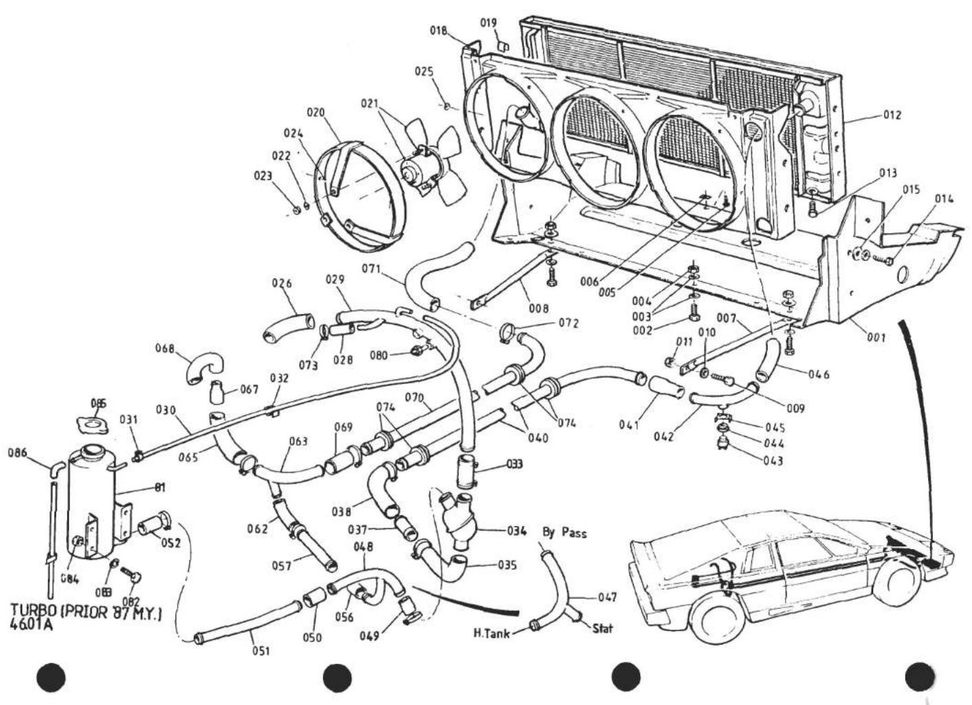
| ILLUSNO. | DESCRIPTION | PART NUMBER | QUANTITY | MAY 1991REMARKS | |
| ALL | |||||
| 46.01A | |||||
| Cooling System Modification KitComprising :- | A082K6049J | 1 | See S/Bulletin 1987/26 | ||
| Header Tank | B082K6048D | 1 | |||
| Blanking Cap, Header Tank | A082K6041F | 1 | |||
| Sensor | A082M6282F | 1 | Sensor used only as a blank | ||
| Grommet, Sensor Mounting | A082M6283F | 1 | |||
| Hose, Header Tank to Expansion Tank | A075L6043V | A/R | |||
| Clip, Hose | A075U6082F | 2 | |||
| Expansion Tank | A082K6040F | 1 | |||
| Pressure Cap, Expansion Tank | A082K6042F | 1 | |||
| Setscrew, M6 x 25, Expansion Tank Fix | A075W1031F | 1 | |||
| Setscrew, M6 x 18, " " " | A075W1029Z | 1 | |||
| Washer, Flat, M6 x 16, " " " | A075W4017Z | 1 | |||
| Washer, Flat, M6 x 12, " " " | A075W4013Z | 3 | |||
| Nut, Nyloc, M6 " " " | A075W3009Z | 2 | |||
| 'Y' Piece, Heater Return Hose to Header Tank | A082K6038D | 1 | |||
| Hose, Header Tank to 'Y' Piece | A082K6045D | 1 | |||
| Junction Pipe, Return | A082K6039D | 1 | |||
| Pipe, Bypass | A082K6044D | 1 | |||
| Hose, Thermostat to Bypass Pipe | A082K6046D | 1 | |||
| Hose, Bypass Pipe to Junction Pipe | A082K6047D | 1 | |||
| Thermostat | B082K6043F | 1 | |||
| Clip, Hose, 8-16mm | A082L6042F | 2 | |||
| Clip, Hose, 25-40mm | A075M6145F | 4 | |||
| Clip, Hose, 20-32mm | B907E6085Z | 4 | |||
| Tie Wrap, Hose Securing | A075W6038Z | 5 | |||
| Grommet, Rear Quarter Trim Panel | X026B0371Z | 1 | |||
| d5p82 | Turbo (Prior '87 M.Y.) 46.01APage 5 | ||||

| ILLUSNO. | DESCRIPTION | PART NUMBER | QUANTITY | MAY 1991 | |
| 1987M.Y.ON | REMARKS | ||||
| 46.01B | |||||
| 1 | Radiator Duct | C082B4491K | 1 | This page for '87 M.Y. 'H.C.' Turbo Cars.For cars prior '87 M.Y. see 46.01A | |
| 3 | Spacer, Radiator Duct Front to Body | A082U5076F | 2 | ||
| 4 | Bolt, M8 x 127, Radiator Duct Front Mounting | A075W2050Z | 2 | ||
| 5 | Nut, Nyloc, M8, Radiator Duct Front Mounting | A075W3010Z | 2 | ||
| 6 | Washer, Flat, Radiator Duct Front Mounting | A075W4021Z | 4 | ||
| 7 | Setscrew, M6 x 25, Duct to Body | A075W1031Z | 6 | ||
| 8 | Washer, 25 O/D, Duct to Body | A075W4017Z | 12 | ||
| 9 | Nut, Nyloc, M6, Duct to Body | A075W3009Z | 6 | ||
| Screw, s/t, Duct to Body | A075W5028Z | 3 | |||
| Spire Nut, Duct to Body | A075W6013Z | 3 | |||
| 12 | Support Stay, Rad. Duct LH | A082K4199K | 1 | 286mm. | |
| 13 | Support Stay, Rad. Duct RH | A082K4198K | 1 | 286mm. | |
| 14 | Setscrew, M6 x 20, Stay to Chassis | A075W1030Z | 2 | ||
| 15 | Washer, Stay to Chassis | A075W4013Z | 2 | ||
| 16 | Nut, Nyloc, M6, Stay to Chassis | A075W3009Z | 2 | ||
| Spacer Washer, Stay to Chassis | A075W4016Z | 4 | |||
| 18 | Setscrew, M6 x 20, Stay to Duct | A075W1030Z | 2 | ||
| 19 | Washer, 25 O/D, Stay to Duct | A075W4017Z | 2 | ||
| 20 | Washer, Flat, Stay to Duct | A075W4013Z | 2 | ||
| 21 | Nut, Nyloc, M6, Stay to Duct | A075W3009Z | 2 | ||
| 23 | Radiator | E082K4101F | 1 | R/B A082K4237F | |
| Radiator | A082K4237F | 1 | |||
| 24 | Drain Plug, Radiator | B075K6011F | 1 | ||
| 25 | Setscrew, M6 x 18, Rad. to Duct | A075W1029Z | 4 | ||
| 26 | Washer, 25 O/D, Rad. to Duct | A075W4017Z | 4 | ||
| 27 | Washer, Spring ,Rad. to Duct | A075W4035Z | 4 | Thick | |
| 28 | Foam, Rad. top to Body | A079K4001F | 1 | Thin | |
| 29 | Foam, Rad. Bottom to Duct | A089K0131F | 1 | ||
| 30 | Cowl, Rad. Fans | D082K4102K | 1 | ||
| Cowl, Rad. Fans | E082K4102K | 1 | Fettle to fit Rad: A082K4237F | ||
| 31 | Edge Clip, Cowl to Radiator | A079W6187F | 12 | ||
| 32 | Screw, s/t, Cowl to Radiator | A075W5014F | 3 | ||
| 33 | Spire Nut, Cowl to Radiator | A075W6013Z | 3 | Turbo H.C. ('87 M.Y. On) | |
| 34 | Fan Shroud & Motor Mounting | A079K4174F | 3 | 46.01B | |
| Page 1 | |||||
| d3p4l | |||||

| ILLUS NO. | DESCRIPTION |  PART NUMBER PART NUMBER | QUANTITY | MAY 1991REMARKS | |
| 1987M.Y.ON | |||||
| 46.01B | |||||
| 35 | Pop Rivet, Shroud to Cowl | A075W6090Z | 18 | This page for '87 M.Y. 'H.C.' Turbo Cars.For cars prior '87 M.Y. see 46.01A | |
| Washer, Pop Rivet | A075W4001Z | 18 | |||
| 37 | Fan Motor, Radiator Cooling | A082K6026H | 3 | ||
| 38 | Fan, Radiator Cooling | A082K6027H | 3 | ||
| Washer, Fan to Motor Shaft | A082K6028F | 3 | |||
| Spring Clip, Fan to Motor Shaft | A082K6029F | 3 | |||
| 41 | Washer, Flat, Motor Mounting | A075W4013Z | 9 | ||
| 42 | Nut, Nyloc, M6, Motor Mounting | A075W3009Z | 9 | ||
| 43 | Hose, Radiator Outlet | A082K4108F | 1 | ||
| 44 | Hose Clip, Outlet Hose | A079K6019F | 2 | ||
| 45 | Pipe, Water Feed/Return, through Chassis | A082K4106F | 2 | ||
| 46 | Sheathing, Chassis Strut, Pipe Protection | C082U4775V | 100mm | ||
| 47 | Snapper Clip, Sheathing to Chassis | A082W6275F | 2 | ||
| 48 | Grommet, Water Pipe/Chassis | A082K6022F | 4 | ||
| 55 | Elbow Hose, Return Pipe to Junction Pipe | A082K4196K | 1 | ||
| 56 | Hose Clip | A079K6019F | 2 | ||
| 57 | Junction Pipe, Header Take-Off | A082K4191F | 1 | ||
| 58 | Grommet, Junction Pipe/Chassis | A082U6109F | 1 | ||
| 59 | Hose, Pump Inlet | A082K4190F | 1 | ||
| 60 | Hose Clip | A079K6019F | 2 | ||
| 61 | Rubber Pad, Hose/Chassis | A082U5008F | 1 | ||
| 62 | Hose, Header Tank Feed | A075K0119F | 1 | ||
| 63 | Connector Pipe, Header Hose | B075K0111Z | 1 | ||
| 64 | Hose, Connector to Header Tank | A079P4056F | 1 | ||
| 65 | Hose Clip, Header Hose | A079K6018F | 4 | ||
| 66 | 'P' Clip, Header Hose to Chassis | B907E6229F | 2 | ||
| Tie Wrap, 290mm, Hose Securing | A075W6045Z | 1 | |||
| 67 | Hose Clip | A910E6389F | 1 | ||
| 68 | Hose, Thermostat Housing to Pipe | B912E1839F | 1 | ||
| 70 | Pipe, Engine Outlet | C082K4182F | 1 | ||
| 71 | Bracket, Water Pipe Fixing | A082K4187F | 1 | ||
| 74 | Thermal Switch, Radiator Fans | A079M6200F | 1 | 92/82 Green Coded Includes Grammet | |
| 75 | Grommet, Radiator Fans Thermal Switch | A079M6181F | 1 | ||
| d3p42 | Turbo H.C. ('87 M.Y. On)46.01BPage 2 | ||||

| ILLUS NO. | DESCRIPTION |  PART NUMBER PART NUMBER | QUANTITY | REMARKS | |
| 1987M.Y.ON | |||||
| 46.01B | |||||
| 76 | Clip, Thermal Switch Retention | A079M6138F | 1 | This page for '87 M.Y. 'H.C.' Turbo Cars. | |
| 77 | Hose, Outlet Pipe to Chassis Pipe | A082K4207F | 1 | For cars prior '87 M.Y. see 46.01A | |
| 79 | Hose Clip, Elbow Hose & Water Pipe to Brkt. | A079K6019F | 5 | ||
| 80 | Hose, Reducing | A082K4115F | 1 | ||
| Hose Clip | A079K6019F | 2 | |||
| 82 | Elbow Pipe, Radiator Inlet & Thermal Switch | A082K4119F | 1 | ||
| 83 | Hose, Radiator Inlet | A082K4200K | 1 | ||
| Hose Clip, Radiator Inlet Hose | A079K6019F | 2 | |||
| 85 | Bracket, Water Pipe to Chassis | A082K4192K | 1 | ||
| Screw, Bracket, to Chassis | A075W5016Z | 1 | |||
| Hose Clip, Pipe to Bracket | A075M6145F | 1 | |||
| 86 | Edge Clip, Header Tank Hose | A082W6185Z | 1 | ||
| 87 | Edge Clip, Header Tank Hose | A082W6257F | 2 | ||
| 88 | Header Tank | A082K4206F | 1 | ||
| 89 | Setscrew, M6 x 20, Header Tank Fix | A075W1030Z | 4 | ||
| 90 | Washer, Internal Spring, Header Tank Fix | A075W4046Z | 4 | ||
| 91 | Washer, M6 x 12, Header Tank Fix | A075W4013Z | 4 | ||
| 92 | Pressure Cap, Header Tank, 15 psi | A082K6031F | 1 | ||
| 93 | Hose, Air Bleed | D075K0113Z | 1 | ||
| 94 | Hose Clip, Air Bleed Hose | A036S6160Z | 2 | ||
| Clip, Air Bleed Hose to Airbox | A075W6228F | 2 | |||
| Pop Rivet, Sealed, Clip to Airbox | A085W6259F | 2 | |||
| 97 | Hose, Header Tank Overflow | A075L6043V | 300mm | ||
| 98 | Elbow, Header Tank Overflow Hose | X036J0135Z | 1 | ||
| Clip, Hose to Header Tank | A079W6185Z | 1 | |||
| 99 | Clip, Overflow Hose to Body | A075W6228F | 1 | ||
| 100 | Pop Rivet, Clip Fix | A075W6090Z | 1 | ||
| Washer, Clip Fix | A075W4001Z | 1 | |||
| Clip, Overflow Hose to Chassis | A075W6185Z | 1 | |||
| 103 | Probe, Coolant Level Tell-Tale | A082M6282F | 1 | ||
| 104 | Grommet, Coolant Level Probe | A082M6283P | 1 | ||
| Turbo H.C. ('87 M.Y. On) | |||||
| 46.01B | |||||
| Page 3 | |||||
| d3p43 | |||||

| ILLUS NO. | DESCRIPTION |  PART NUMBER PART NUMBER | QUANTITY | MAY 1991REMARKS | |
| DRYSUMP | WETSUMP | ||||
| 001 | Oil Hose Assembly, Scavenge Pump to Cooler | B082E4082F | 1 | When No Oil Cooler Thermostat Fitted | |
| 002 | Oil Hose Assembly, Scavenge Pump to Thermostat | B082E4109F | 1 | ) | |
| 003 | Thermostat, Oil Cooler | A082E6016F | 1 | ) | |
| Bracket, Thermostat Mounting | A082U4848K | 1 | ) | ||
| Setscrew, M6 x 16, Bracket to Body | A075W1028F | 2 | ) | ||
| Washer, 6 mm, Bracket to Body | A075W4017F | 2 | )With Oil Cooler Thermostat | ||
| 004 | Nut, Nyloc, M6, Bracket to Body | A075W3009F | 2 | ) | |
| Oil Hose Assembly, Thermostat to Cooler | A082E4107F | 1 | ) | ||
| 005 | Oil Hose Assembly, Cooler to Thermostat | A082E4108F | 1 | ) | |
| 006 | Oil Hose Assembly, Thermostat to Tank | A082E4093F | 1 | ) | |
| Oil Hose Assembly, Cooler to Tank | A082E4093F | 1 | When No Oil Cooler Thermostat Fitted | ||
| Grommet, Tank Return Pipe/Body | A082U4779F | 1 | |||
| Ring, Grommet Retaining | A079L4034F | 1 | |||
| Screw, Grommet Ring | A075W5014Z | 4 | |||
| Oil Hose Assembly, Stat to Engine | A082E4105F | 1 | |||
| Oil Hose Assembly, Engine to Stat (5/8"@ Stat) | A082E4105F | 1 | With Oil Cooler Thermostat A910E6550F | ||
| 012 | Oil Hose Assembly, Engine to Stat (3/4"@ Stat) | A082E4112F | 1 | With Oil Cooler Thermostat A082E6016F | |
| 013 | Thermostat, Oil Cooler | A910E6550F | 1 | 4 x 5/8" BSP > If Thermostat | |
| Thermostat, Oil Cooler | A082E6016F | 1 | 3 x 5/8" 1 x 3/4" BSP > Fitted | ||
| 014 | Bracket, Thermostat Mounting | A082U4842F | 1 | For A910E6550F > (Prior to | |
| Bracket, Thermostat Mounting | B082U4842F | 1 | For A082E6016F > November '85) | ||
| Nut, Nyloc, M6 | A075W3009F | 2 | > | ||
| Washer, Flat | A075W4015F | 2 | > | ||
| d6p1 | Turbo 46.03APage 1 | ||||

| ILLUSNO. | DESCRIPTION |  PART NUMBER PART NUMBER | QUANTITY | FEB 1987REMARKS | |
| DRYSUMP | WETSUMP | ||||
| 46.03A | |||||
| 015 | Connector Union, Oil Hose, Eng. to Cooler | A082E6026F | 1 | 3/4" - 5/8" BSP) | |
| 016 | Connector Union, Oil Hose, Cooler to Eng. | A082E6025F | 1 | 5/8" BSP x 2 )Interim Spec. | |
| Mounting Brkt. Connector Unions | A082E4135F | 1 | Without Thermostat | ||
| Clamp Plate, Unions to Brkt. | A082E4136F | 1 | )(Nov.'85 to VIN 82 D 2321) | ||
| Spacer, Union Locking | A082E4141F | 1 | ) 82 - 0672 | ||
| Nut, Nyloc, M8, Clamping & Fixing | A075W3010F | 2 | ) | ||
| Washer, 25 O/D, Brkt. to Chassis | A075W4021Z | 1 | ) | ||
| Oil Hose Assembly, Cooler/Stat LH | A082E4103F | 1 | > | ||
| 016 | Oil Hose Assembly, Cooler/Stat RH | A082E4101F | 1 | R/B A082E4111F >With Thermostat | |
| Oil Hose Assembly, Cooler/Stat RH | A082E4111F | 1 | Inc. 45° Thermostat Union> | ||
| Oil Hose Assembly, Eng/Cooler, Cooler/Eng. | A082E4134F | 2 | Without Thermostat | ||
| 020 | 'P' Clip, Hose to Chassis | A075H6018F | 4 | ||
| 021 | Screw 'P' Clips | A075W5036F | 3 | ||
| 022 | Nut, Spire | A075W6011F | 3 | ||
| 023 | Clip, Oil Hose to Front Frame | A075W6230F | 4 | ||
| 024 | Screw, Clip Fixing | A075W5034Z | 4 | ||
| 025 | Spire Nut, Clip Fixing | A075W6011Z | 4 | ||
| Grommet, Oil Hose/Chassis | A082K6022F | 6 | With Hoses on outside of Chassis Backbone | ||
| Edge Protector, Oil Hose/Chassis Rr.Diaphram | AX75L6020V | 190mm | With Hoses run through Chassis Backbone | ||
| Foam Tube, Oil Hose/Chassis Front X-member | A082E6022V | 85mm | |||
| Tie Wrap, Oil Hose | A075W6038F | 10 | |||
| 030 | Cooler, Oil (Silver) | A907E1219F | 1 | 1 | 252mm Pipe Centres. Prior Nov. '85 |
| Cooler, Oil (Black) | A082W6024F | 1 | 325mm Pipe Centres. Nov. '85 on | ||
| Plate, Spreader | A082K4103F | 2 | 2 | ||
| Setscrew, M6 x 20 | A075W1030Z | 4 | 4 | ||
| Washer, 6mm, Flat | A075W4013Z | 4 | 4 | ||
| Nut, Nyloc, M6 | A075W3009Z | 4 | 4 | ||
| d6p2 | Turbo 46.03APage 2 | ||||
| 3/4" - 5/8" BSP) | |
| 5/8" BSP x 2 | )Interim Spec. |
| )Without Thermostat | |
| )(Nov.'85 to VIN 82 D 2321) | |
| ) 82 - 0672 | |
| ) | |
| ) | |
| With Hoses on outside of Chassis Backbone With Hoses run through Chassis Backbone |
| 252mm Pipe Centres. Prior Nov. '85 |
| 325mm Pipe Centres. Nov. '85 on |

TURBO
47.01A


| ILLUS NO. | DESCRIPTION |  PART NUMBER PART NUMBER | QUANTITY | REMARKS | |
| ALL | |||||
| 47.01A | |||||
| 001 | Master Cylinder, ClutchClevis Pin, Clutch Pedal to Clevis'R' Pin, Clutch Pedal to ClevisPressure Washer, Clutch Pedal to Clevis | C079J6013FA082J4197FA075W6175F | 111 | ||
| 002 | Washer, Master Cylinder Fix | A082W4103FA075W4020Z | 12 | ||
| 003 | Nut, Nyloc, M8, Master Cyl. FixService Kit, Master CylinderFiller Cap | A075W3010ZA036J6091ZA079J6038F | 1211 | ||
| 004 | Pipe, Flexible, Master to Slave CylinderPipe, Flexible, Master to Slave Cylinder | A082J4088FA082J4089F | 11 | RHDLHD | |
| 006 | Slave CylinderSetscrew, M8 x 25, Slave Cylinder Fix | A082Q6020FA075W1039Z | 12 | ||
| 007 | Washer, Spring, Slave Cylinder Fix | A075W4036ZA082Q6024F | 11 | ||
| 008 | Service Kit, Slave CylinderBleed Screw, Slave Cylinder | A082Q6025FA082Q0058F | 11 | ||
| 009 | Pushrod, Clutch OperatingPressure Plate Assy. (Straight Fingers) | A082Q4006FA082Q4018F | 11 | R/B A082Q4018F With Rel/Brg. A085Q4016JUse With Rel/ Brg. A085Q4016J | |
| 010 | Pressure Plate Assy. (Curved Fingers)* | A082Q4018F | 1 | R/B A082Q4019F | |
| 011 | Friction PlateFriction Plate | A082Q4007FA082Q4019F | 11 | ||
| 012 | Setscrew, Cover to Flywheel | A075W1012Z | 6 | ||
| 013 | Washer, Spring, Cover to Flywheel | A075W4032Z | 6 | ||
| 015 | Release Bearing Assembly (Curved Face) | A082Q4013J | 1 | Use With P.P. Assy. A082Q4006F | |
| Release Bearing Assembly (Flat Face) | A085Q4016J | 1 | Use With P.P. Assy. A082Q4018F | ||
| 017 | Spring Clip, Release Brg. to Fork | A082Q6021F | 2 | ||
| 018 | Fork, Clutch Release | B079Q6009F | 1 | ||
| 020 | Ball Pin, Fork Pivot | A082F0752F | 1 | ||
| 021 | Split Pin, Fork to Pivot | A079Q6016F | 1 | ||
| 022 | Grommet, Fork to Housing | A079Q6017F | 1 | ||
| 023 | Adjuster Screw, Release Fork | A079Q6010F | 1 | ||
| 024 | Locknut, Adjuster Screw | A079W3048F | 1 | ||
| * From Eng. No. 22728 | |||||
| Turbo 47.01A | |||||
| d6p3 | |||||
PREVIOUS TYPE

'C35' TYPE

TURBO
47.02A


INTRODUCTION OF TYPE C35 GEARBOX ASSEMBLY
From early 1984, all Esprit models were fitted with the type 'C35' gearbox. All Esprit gearboxes are stamped with a Lotus serial number, repeated on its matched clutch housing. All gearboxes stamped with a 'C' prefix to the serial number are type C35.
Gearboxes with the following serial numbers (without 'C' prefix) are also type C35
2914 to 2920 2954 to 2974 3023 to 3024 3028 to 3039 3044 to 3152
All numbers are inclusive, and are to be found on the top front of the gearbox and adjacent surface of the clutch housing
Drain Plug
C35 type gearboxes have only one oil drain plug which is situated beneath the main case. They are not fitted with the additional rear case drain plug as used on previous type gearboxes.
TU3AAK/2
Level Plug
The oil level plug (painted yellow) is fitted in the left hand side of the case, as before, and should not be confused with a similar plug (blanking) positioned higher up on the same side of the gearbox.
Exhaust Silencer Mounting Bracket
The C35 type gearbox rear cover incorporates a large cast boss, necessitating a revised silencer mounting bracket and fixings.
Turbo 47.02A
FEB 1987
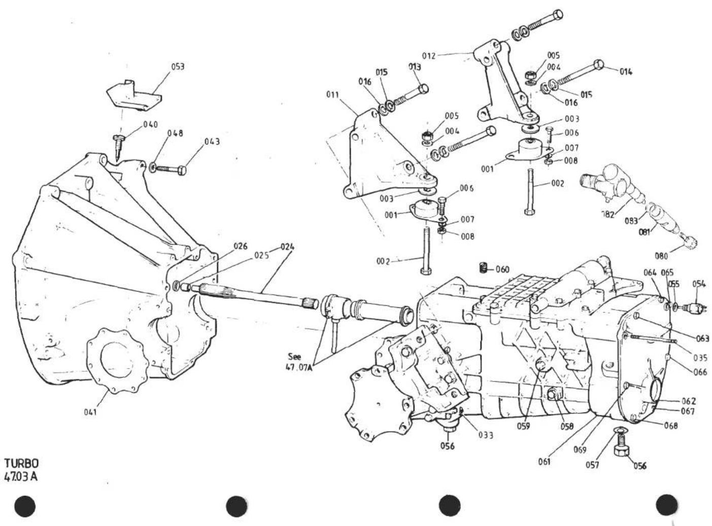
| ILLUSNO. | DESCRIPTION |  PART NUMBER PART NUMBER | QUANTITY | FEB 1987REMARKS | |
| PRIORC35 | C35 | ||||
| Gearbox & Clutch Housing Assy. | B082F4000J | 1 | For Identification of C35, See 47.02A | ||
| Gearbox & Clutch Housing Assy. | A082F4072F | 1 | R/B A/B 082F4072J | ||
| Gearbox & Clutch Housing Assy. | B082F4072F | 1 | Prior to '85 M.Y. | ||
| Clutch Housing | C082F4001F | 1 | '85 M.Y. on) Must be machined to) Match Gearbox Casing | ||
| Clutch Housing | E082F4001F | 1 | |||
| 001 | Rubber Mounting, Engine/G.Box Rear | B085E6012F | 2 | 2 | |
| 002 | Bolt 7/16", Mtg. to G/.Box Brkt. | B085E4095F | 2 | 2 | |
| 003 | Washer, Snubber, Mtg. to G./Box Brkt. | A075W4006F | 2 | 2 | |
| 004 | Washer, Flat, Mtg. Bolt | A075W4005F | 2 | 2 | |
| 005 | Nut, Nyloc, 7/16" Mtg. Bolt | A075W3004F | 2 | 2 | |
| 006 | Setscrew, M8 x 20, Mtg. to Chassis | A075W1038F | 4 | 4 | |
| 007 | Washer, Flat, Mtg. to Chassis | A075W4020F | 8 | 8 | |
| 008 | Nut, Nyloc, M8, Mtg. to Chassis | A075W3010F | 4 | 4 | |
| 011 | Bracket, Gearbox/Caliper Mtg. LH | A082F4039K | 1 | ||
| Bracket, Gearbox/Caliper Mtg. LH | A082F4073K | 1 | |||
| 012 | Bracket, Gearbox/Caliper Mtg. RH | A082F4038K | 1 | ||
| Bracket, Gearbox/Caliper Mtg. RH | A082F4074K | 1 | |||
| 013 | Bolt, ML4 x 75, Bracket/Gearbox | A082F6293F | 2 | 2 | |
| 014 | Bolt, ML4 x 90, Bracket/Gearbox | A079F6013F | 2 | 2 | |
| 015 | Washer, Spring, Bracket to Gearbox | A079W4068F | 4 | 4 | |
| 016 | Washer, Flat, Bracket to Gearbox | A079W4054F | 4 | 4 | |
| 024 | Clutch Shaft | B085F4068J | 1 | 1 | Includes Spigot Sleeve A089F0404F |
| 025 | Sleeve, Clutch Shaft Spigot (18.5mm Long) | A089F0404F | 1 | 1 | Replaces Earlier 15mm Sleeve |
| 026 | Thrust Washer, Nylon, Shaft/Spigot Brg. | A079F4029F | 1 | 1 | |
| 033 | Plug, Gearbox Joint Face | A085F4069K | 1 | ||
| 035 | Stud, Silencer Mounting Bracket | A079F4030F | 1 | 1 | |
| Nut, M7, Nyloc | A079F6023F | 1 | 1 | ||
| 040 | Pointer, Engine Timing | A082F0753F | 1 | 1 | |
| 041 | Gasket, Output Shaft Housing | B079F6028F | 1 | 1 | |
| 043 | Bolt, ML0 x 35, Clutch Housing/Engine | A075W2051Z | 2 | 2 | Not Dry Sump |
| Bolt, ML0 x 50, Clutch Housing/Engine | A075W2054Z | 5 | 5 | ||
| Bolt, ML0 x 60, Clutch Housing/Engine | A075W2055Z | 2 | 2 | Turbo 47.03APage 1 | |
| d6p4 | |||||
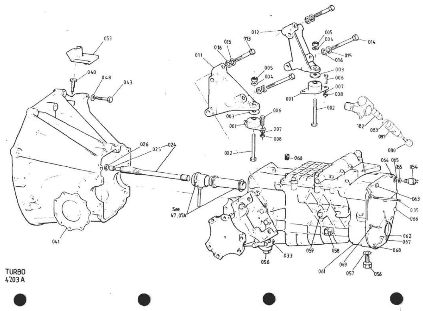
| ILLUSNO. | DESCRIPTION |  PART NUMBER PART NUMBER | QUANTITY | REMARKS | |
| PRIORC35 | C35 | ||||
| 47.03A | |||||
| Bolt, M10 x 75, Clutch Housing/Engine | A075W2059Z | 2 | 2 | Dry Sump Only | |
| Nut, Nyloc, M10, Clutch Housing/Engine | A075W3011Z | 2 | 2 | 8 Used on Dry Sump | |
| 048 | Washer, Flat, Clutch Housing/Engine | A075W4024Z | 11 | 11 | 12 Used on Dry Sump |
| Shim, Clutch Housing to Sump | A911E1430F | A/R | A/R | ||
| 053 | Cover, Timing Aperture | A082F0762K | 1 | 1 | |
| 054 | Switch, Reverse Light | A079M6014F | 1 | 1 | |
| 055 | Washer, Reverse Light Switch | A079M6052F | 1 | 1 | |
| 056 | Drain Plug | A079F6227F | 2 | ||
| Drain Plug | A082F6331F | 1 | |||
| 057 | Washer, Drain Plug | A079F6205F | 2 | 1 | |
| 058 | Level Plug | A079F6222F | 1 | 1 | |
| 059 | Blanking Plug | A079F6222F | 1 | ||
| Washer, Level/Blanking Plug | A079F6223F | 1 | 2 | ||
| 060 | Air Vent, Breather | A079F6211F | 1 | 1 | If Fitted |
| 061 | End Housing | A079F6201F | 1 | ||
| End Housing | A082F6320F | 1 | |||
| 062 | End Cover | A079F6226F | 1 | ||
| End Cover | A082F6324F | 1 | |||
| Core Plug, End Cover Blanking | A082F6346F | 1 | |||
| 063 | Screw, M7 x 100, Rear Cover Fix | A079F6202F | 1 | ||
| Screw, M7 x 28, Rear Cover Fix | A079F6190F | 1 | |||
| 064 | Screw, M7 x 40, Rear Cover Fix | A079F6219F | 1 | ||
| Screw, M7 x 28, Rear Cover Fix | A079F6190F | 1 | |||
| 065 | Screw, M7 x 95, Rear Cover Fix | A079F6203F | 1 | 1 | |
| 066 | Bolt, M7 x 45, Silencer Brkt/Rear Cover | A079F4031F | 1 | 1 | |
| 067 | Screw, M7 x 100, Silencer Brkt/Rear Cover | A079F6202F | 1 | ||
| Screw, M7 x 45, Silencer Brkt/Rear Cover | A079F4031F | 1 | |||
| 068 | Screw, M7 x 25, Silencer Brkt/Rear Cover | A079F6191F | 1 | ||
| Screw, M7 x 45, Silencer Brkt/Rear Cover | A079F4031F | 1 | |||
| 069 | Screw, M9 x 65, Rear Cover Fix | A079F6217F | 1 | 1 | Turbo 47.03APage 2 |

| ILLUS NO. | DESCRIPTION |  PART NUMBER PART NUMBER | QUANTITY | REMARKS | |
| PRIOR C35 | C35 | ||||
| 47.03A | |||||
| Stop, Speedo Pinion | A079F6206F | 1 | 1 | ||
| Nut, Speedo Pinion Stop | A079F6216F | 1 | |||
| Nut, Speedo Pinion Stop | A082F6345F | 1 | |||
| Screw, M9 x 30, Rear Cover/Main Case | A079F6204F | 5 | 5 | ||
| Screw, M9 x 25, Rear Cover/Main Case | A079F6221F | 3 | |||
| Outflow Plate | A079F6269F | 1 | ) Inside End Cover | ||
| Outflow Tube | A079F6268F | 1 | |||
| Oil Deflector | A079F6270F | 1 | |||
| Oil Deflector | A082F6350F | 1 | ) | ||
| Stud, M12 x 73, G/Box to Clutch Hsg. | A079F6215F | 2 | 2 | ||
| Stud, M12 x 58, G/Box to Clutch Hsg. | A079F6214F | 2 | 2 | ||
| Washer, 12mm, G/Box to Clutch Hsg. | A079F6213F | 4 | 4 | ||
| Nut, M12, G/Box to Clutch Hsg. | A079F6212F | 4 | 4 | ||
| 080 | Speedo Driven Gear, (17 Teeth) | A079F6054F | 1 | 1 | |
| 081 | Nylon Bush, Speedo Driven Gear | B079F6228F | 1 | Replaces Earlier Bush With Steel Cap | |
| Nylon Bush, Speedo Driven Gear | A082F6330F | 1 | |||
| 082 | Right Angle Drive, Speedo | A079F6292F | 1 | 1 | R/B B079F6292F With 'O' Ring |
| Right Angle Drive, Speedo | B079F6292F | 1 | 1 | Use With 'O' Ring A082F6315F | |
| 083 | 'O' Ring, Speedo Angle Drive | A082F6315F | 1 | 1 | |

| ILLUSNO. | DESCRIPTION |  PART NUMBER PART NUMBER | QUANTITY | MAY 1991REMARKS | |
| ALL | |||||
| 47.05A | |||||
| 1 | Gear Lever AssemblyRoll Pin, Gear Lever, M5 x 40Gear Lever AssemblyGear Lever AssemblyGear Lever | A079F6002FA074F6013FA082F6313FA082F4075FA082F4088HB079F4016FA082F4063FA079F4017FA082F4064F | 1111111111111111111111111111111111111111111111111111111111111111111111111111111111111111111111111111 | M7 Knob Thread R/B A082F6313FFor Gear Lever Ass. A079F6002FM8 Knob Thread R/B A082F4075FM8 Knob ThreadM8 Knob Thread | |
| 2 | Gear LeverKnob, Gear Lever, M7Knob, Gear Lever, M8 | B079F4016FA082F4063FA079F4017FA082F4064F | 11111111111111111111111111111111111111111111111111111111111111 | For Gear Lever Assy. A079F6002FFor Gear Lever Assy. A082F6313F/A082F4075FR/B A079W6245 | |
| 3 | Spacer, M7 Gear KnobLock Ring, M8 Gear Knob | B079F4012FA082F4062FA079W6198FA079W6245FA079F4022FA079W6199FA082K6032V | 11111111111111111111111111111111111111111111111111111111111111111111111111111111111111111111111111 | Use With 240mm Extension RodUse With 442/422 Extension Rod | |
| 4 | Reverse GateReverse GateSpirol Pin, 5 x 14, Bellcrank to Cable YokeSpirol Pin, 3/16" x 14 | A079W6198FA079W6245FA079F4022FA079W6199FA082K6032V | 11111111111111111111111111111111111111111111111111111 | If Fitted | |
| 5 | Yoke, Lever Assy. to Crossgate CableSpirol Pin, 5 x 18, Cable to YokeLockwire, S/Steel Pin Retention | C079F4015FD079F4015FA079W4051FA082F4042CB075Q6001Z | 0.2m112111111111111111111111111111111111111111111111111111111111111111111111111111111111111111111111111111 | ||
| 6 | Crossgate CableCrossgate Cable | A079F4015FA079F4015FA079W4051FA082F4042C | 211111111111111111111111111111111111111111111111111111111111111111111111111111111111111111111111111 | R/B B082F4065K | |
| 7 | Washer, Shakeproof, 14mm, Cable/ChassisBracket, Cable Abutment Rear | B075Q6001Z | 1 | ||
| 8 | Dust Cover, Cable RearRod, Crossgate Cable Extension, 240mmRod, Crossgate Cable Extension, 442mmRod, Crossgate Cable Extension, 422mmLocknut/Cable Stiffener | B082F4044KB082F4065KB082F4065K | 11111111111111111111111111111111111111111111111111111111111111111111111111111111111111111111111111 | ||
| 9 | Locknut/Cable StiffenerLocknut, Crossgate Cable to Ext. Rod | A075W3020ZA075W6034FA075W6175FA075W4000Z | 1111111111111111111111111111111111111111111111111111111111111111111111111111 | Use With 240mm Extension RodUse With 442/422 Extension Rod | |
| 10 | Clevis Pin, Rod to BellcrankSpring Clip, Clevis PinWasher, Clevis Pin | C082F4043FF082F4043FA075J6003FC079F4014F | 111111111111111111111111111111111111111111111111111111111111111111 | ||
| 11 | Bellcrank Lever, CrossgateBellcrank Lever, Crossgate | C082F4043FF082F4043FA075J6003FC079F4014F | 111111111111111111111111111111111111111 | R/B F082F4043F | |
| 12 | Bush, Bellcrank LeverPivot Pin, Bellcrank Lever | Turbo 47.05APage 1 | |||
| d6p7 | |||||
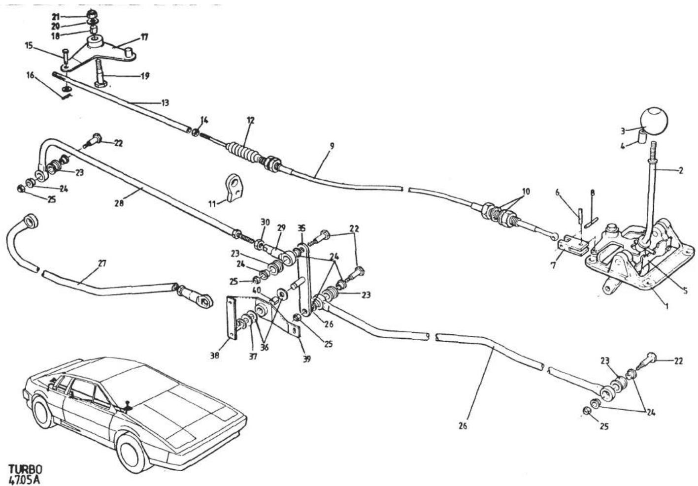
| ILLUSNO. | DESCRIPTION |  PART NUMBER PART NUMBER | QUANTITY | REMARKS | |
| ALL | |||||
| 47.05A | |||||
| 20 | Washer, Bellcrank Pivot | A075W4024Z | 2 | ||
| 21 | Nut, Nyloc, M10, Bellcrank Pivot Bolt | A075W3011Z | 1 | ||
| 22 | Pivot Pin, Gearchange Tubes | A079F6004F | 4 | M7 Thread | |
| Pivot Pin, Gearchange Tubes | A082F4070F | 4 | M8 Thread | ||
| 23 | Rubber Bush, Tube End | A079F6007F | 4 | ||
| 24 | Bearing, Nylon, Tube End | A079F6008F | 8 | ||
| 25 | Nut, Pivot Pin | A079F6023F | 4 | M7 Thread | |
| Nut, Pivot Pin | A907E6284F | 4 | M8 Thread | ||
| Washer, 8mm, Gear Lever to Front Tube | A075W4020Z | 1 | If Fitted | ||
| 26 | Tube, Gearchange, Front | A082F4053J | 1 | ||
| 27 | Tube, Gearchange, Rear | A082F4052J | 1 | Prior to '85 M.Y. | |
| 28 | Tube, Gearchange, Rear | A082F4108J | 1 | '85 Model Year | |
| 29 | Adjustable End, Rear G/Change Tube | A085F4058F | 1 | ||
| 30 | Locknut, Adjustable End | A075W3024F | 1 | ||
| Relay Lever, Gearchange, 0.86:1 Ratio | A082F4050K | 1 | |||
| 35 | Relay Lever, Gearchange, 1:1 Ratio | A082F4059F | 1 | R/B B082F4059F With M8 Pivot Pins | |
| Relay Lever, Gearchange, 1:1 Ratio | B082F4059F | 1 | Uses M8 Pivot Pins | ||
| Washer, 10mm, Relay Lever Pivot | A075W4024F | 1 | )Use With Relay Lever A082F4050K | ||
| Split Pin, Relay Lever Pivot | A075W6176F | 1 | ) | ||
| 36 | Thrust Washer, Relay Lever Pivot | A082F6301F | 2 | > | |
| 37 | Washer, Flat, Relay Lever Pivot | A075W4028Z | 1 | >Use With Relay Lever A/B082F4059F | |
| 38 | 'E' Clip, Relay Lever Pivot | A082F6302F | 1 | > | |
| 39 | Pivot Bracket, Relay Lever (Inc. Bush) | A082F4102J | 1 | Chassis Mounted. Earlier Cars | |
| 40 | Bush, Relay Lever Pivot | A912E6593F | 1 | Used Pivot on Engine Mounting Leg | |
| Setscrew, M6 x 18, Pivot Brkt./Chassis | A075W1029Z | 3 | For Bracket A082F4102J | ||
| Nut, Nyloc, M6, Pivot Brkt/Chassis | A075W3009Z | 3 | |||
| Washer, Flat, Pivot Brkt./Chassis | A075W4015Z | 3 | |||
| Edge Protector, Pivot Brkt/A/C Pipes | AX75L6020V | * | 205mm A/C Cars Only | ||
| FEB 1987 | |||||
| Turbo 47.05A | |||||
| Page 2 | |||||
| d6p8 | |||||
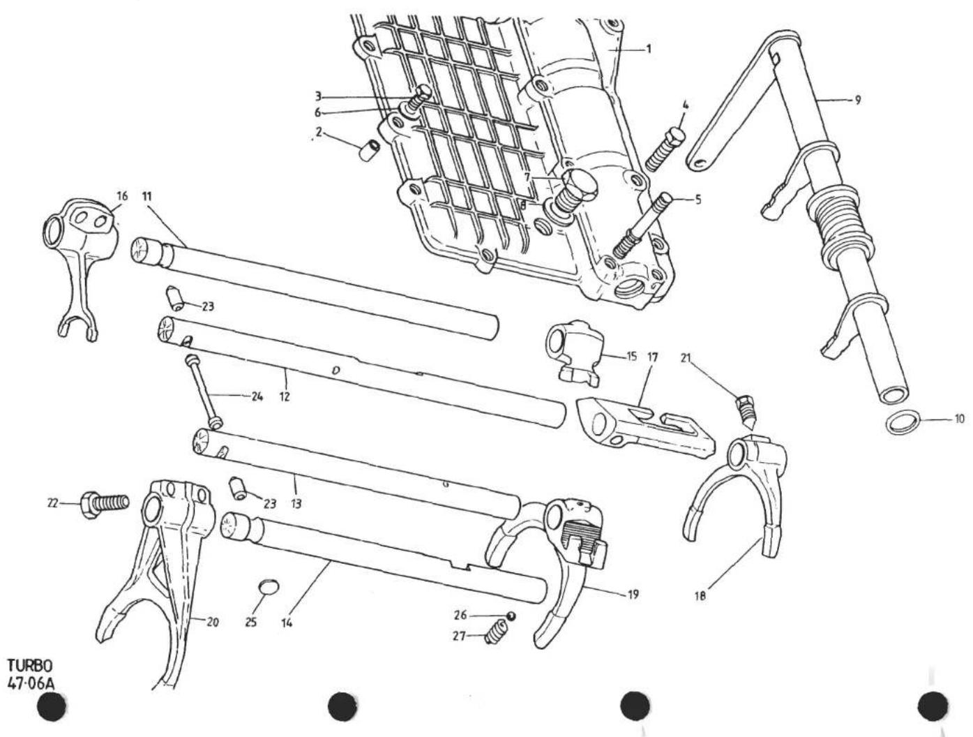
| ILLUS NO. | DESCRIPTION |  PART NUMBER PART NUMBER | QUANTITY | REMARKS | |
| PRIOR C35 | C35 | ||||
| 47.06A | For Identification of C35 See 47.02A | ||||
| 1 | Top Cover & Cross Shaft Bearing Cap | A079F6177F | 1 | ||
| Top Cover & Cross Shaft Bearing Cap | A082F6327F | 1 | |||
| 2 | Dowel, Top Cover Locating | A079F6189F | 4 | 4 | |
| 3 | Setscrew, M7 x 35, Top Cover | A079F6192F | 3 | 2 | |
| Setscrew, M7 x 25, Top Cover | A079F6191F | 5 | 4 | ||
| 4 | Setscrew, M7 x 28, Top Cover | A079F6190F | 4 | ||
| Setscrew, M7 x 50, Top Cover | A079F6198F | 2 | 4 | ||
| 5 | Shouldered Screw | A079F6197F | 2 | ||
| Shouldered Screw | 1 | ||||
| 6 | Washer, Top Cover Screw | A079F6200F | 4 | 4 | |
| 7 | Filler Plug | A079F6178F | 1 | 1 | |
| 8 | Gasket, Filler Plug | A079F6179F | 1 | 1 | |
| 9 | Cross Shaft Assembly | A082F0755K | 1 | ||
| Cross Shaft Assembly | A082F4060F | 1 | R/B B082F4060FUse With M8 Linkinge Pivot BoltPrior to '85 M.Y.1985 Model Year on | ||
| Cross Shaft Assembly | B082F4060F | 1 | |||
| Cross Shaft Assembly | C082F4107F | 1 | |||
| 10 | 'O' Ring, Cross Shaft | A079F6055F | 2 | ||
| 'O' Ring, Cross Shaft | A082F6312F | 2 | |||
| 11 | Selector Shaft, Reverse | A079F6172F | 1 | 1 | |
| 12 | Selector Shaft, 5th | A079F6171F | 1 | ||
| Selector Shaft, 5th | A082F6340F | 1 | |||
| Plunger, Interlock Relay (Thro' Rod) | A082F6339F | 1 | |||
| 13 | Selector Shaft, 3rd & 4th | A079F6170F | 1 | ||
| Selector Shaft, 3rd & 4th | A082F6338F | 1 | |||
| Plunger, Interlock Relay (Thro' Rod) | A082F6339F | 1 | |||
| 14 | Selector Shaft, 1st & 2nd | A079F6169F | 1 | 1 | |
| 15 | Relay Dog, Reverse Selector Shaft | A079F6165F | 1 | 1 | |
| 16 | Selector Fork, Reverse | A079F6164F | 1 | 1 | |
| 17 | Relay Dog, 5th Selector Shaft | A079F6160F | 1 | ||

| ILLUS NO. | DESCRIPTION |  | QUANTITY | REMARKS | |
| PART NUMBER | ALL | ||||
| 47.11A | |||||
| 13 | Adjusting Washer, 3.00 Adjusting Washer, 3.05 Adjusting Washer, 3.10 Adjusting Washer, 3.15 Adjusting Washer, 3.20 Adjusting Washer, 3.25 Adjusting Washer, 3.30 Adjusting Washer, 3.35 Crown Wheel and Pinion Roller Bearing | A079F6259F A079F6260F A079F6261F A079F6262F A079F6263F A079F6264F A079F6265F A079F6266F A079F6267F A079F6258F | >1 >1 >1 >1 2 | Selective | |
| 14 | |||||
| 15 | |||||
| d6p15 | Turbo 47.11A Page 2 | ||||

TURBO
47.15A


| ILLUS NO. | DESCRIPTION |  PART NUMBER PART NUMBER | QUANTITY | REMARKS | |
| ALL | |||||
| 47.11A | |||||
| 1 | Housing | A079F6231F | 1 | ||
| 2 | Planet Wheel | A079F6232F | 2 | ||
| 3 | Satellite Wheel | A079F6233F | 4 | ||
| 4 | Satellite Spindle, Long | A079F6234F | 1 | ||
| 5 | Satellite Spindle, Short | A079F6235F | 2 | ||
| 6 | Locking Screw, Satellite Wheel | A079F6237F | 3 | R/B A082F6318F | |
| Locking Screw, Satellite Wheel | A082F6318F | 3 | |||
| 7 | Locking Screw, Crown Wheel | A079F6238F | 5 | ||
| 8 | Planet Wheel Washer 1.52 | A079F6239F | ) | ||
| Planet Wheel Washer 1.58 | A079F6240F | ) | |||
| Planet Wheel Washer 1.64 | A079F6241F | ) 1 | Selective | ||
| Planet Wheel Washer 1.70 | A079F6242F | ) | |||
| Planet Wheel Washer 1.76 | A079F6243F | ) | |||
| Planet Wheel Washer 1.82 | A079F6244F | ) | |||
| 9 | Satellite Gear Washer 1.54 | A079F6245F | > | ||
| Satellite Gear Washer 1.62 | A079F6246F | > | |||
| Satellite Gear Washer 1.70 | A079F6247F | > 1 | Selective | ||
| Satellite Gear Washer 1.78 | A079F6248F | > | |||
| 10 | Crosshead Bush | A079F6236F | 1 | ||
| 11 | Spacer | A079F6249F | 1 | ||
| 12 | Spacer, 2.9 | A079F6250F | ) | ||
| Spacer, 3.3 | A079F6251F | ) | |||
| Spacer, 3.7 | A079F6252F | ) | |||
| Spacer, 4.1 | A079F6253F | ) 1 | Selective | ||
| Spacer, 4.5 | A079F6254F | ) | |||
| Spacer, 4.9 | A079F6255F | ) | |||
| Spacer, 5.3 | A079F6256F | ) | |||
| Spacer, 5.7 | A079F6257F | ) | |||
| FEB 1987 | Turbo 47.11A | ||||
| d6p14 | Page 1 | ||||

TURBO
47.11A


| ILLUSNO. | DESCRIPTION | PART NUMBER | QUANTITY | MAY 1991 | |
| PRIORC35 | C35 | REMARKS | |||
| 47.07A | |||||
| Spacer Washer, 2.61 | A079F6143F | ) | |||
| Spacer Washer, 2.65 | A079F6144F | ) | |||
| Spacer Washer, 2.69 | A079F6145F | ) | |||
| Spacer Washer, 2.73 | A079F6146F | ) 1 | 1 | Selective | |
| Spacer Washer, 2.77 | A079F6147F | ) | |||
| Spacer Washer, 2.81 | A079F6148F | ) | |||
| Spacer Washer, 2.85 | A079F6149F | ) | |||
| Spacer Washer, 2.89 | A079F6150F | ) | |||
| Spacer Washer, 2.93 | A079F6151F | ) | |||
| Spacer Washer, 2.97 | A079F6152F | ) | |||
| Spacer Washer, 3.01 | A079F6153F | ) | |||
| Spacer Washer, 3.05 | A079F6154F | ) | |||
| Spacer Washer, 3.09 | A079F6155F | ) | |||
| Spacer Washer, 3.13 | A079F6156F | ) | |||
| 29 | Driven Pinion, 3rd/4th Secondary Shaft | A079F6157F | 1 | 1 | |
| 30 | Double Ball Bearing, Secondary Shaft Rear | A079F6115F | 1 | R/B A082F6326F | |
| Double Ball Bearing, Secondary Shaft Rear | A082F6326F | 1 | |||
| 31 | Driven Pinion, 5th, Secondary Shaft | A079F6158F | 1 | 1 | |
| 32 | Nut/Speedo Drive Gear | A079F6114F | 1 | 1 | |
| 33 | Idler Gear, Reverse, Inc. Bush | A079F6112F | 1 | 1 | |
| 34 | Spindle, Reverse Idler Gear | A079F6099F | 1 | 1 | |
| 35 | Screw, Reverse Gear Spindle | A079F6100F | 1 | 1 | |
| 36 | Nut, Reverse Spindle Screw | A079F6101F | 1 | 1 | |
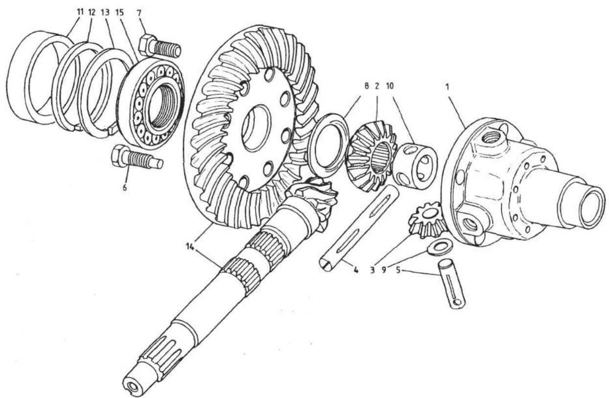
TURBO
47.11A


| ILLUSNO. | DESCRIPTION |  PART NUMBER PART NUMBER | QUANTITY | MAY 1991REMARKS | |
| PRIORC35 | C35 | ||||
| 47.07A | |||||
| 22 | Driven Pinion, 1st, Secondary Shaft | A079F6102F | 1 | 1 | R/B A082F6316FSupplied With Matched Synchro. Ring |
| 23 | Driven Pinion, 2nd, Secondary Shaft | A079F6103F | 1 | 1 | |
| Driven Pinion, 2nd, Secondary Shaft | A082F6316F | 1 | 1 | ||
| 24 | Needle Roller Bearing, 1st/2nd Pinion | A079F6104F | 2 | 2 | |
| 25 | Sleeve, 1st/2nd Pinion Bearing | A079F6118F | 2 | 2 | |
| 26 | Synchroniser Assembly, 1st & 2nd | A079F6089F | 1 | ||
| Synchroniser Assembly, 1st & 2nd | A082F6333F | 1 | |||
| 27 | Synchro Ring, 1st & 2nd | A079F6090F | 2 | 2 | |
| 28 | Spacer Washer, 1.65 | A079F6119F | ) | ||
| Spacer Washer, 1.69 | A079F6120F | ) | |||
| Spacer Washer, 1.73 | A079F6121F | ) | |||
| Spacer Washer, 1.77 | A079F6122F | ) | |||
| Spacer Washer, 1.81 | A079F6123F | ) | |||
| Spacer Washer, 1.85 | A079F6124F | ) | |||
| Spacer Washer, 1.89 | A079F6125F | ) | |||
| Spacer Washer, 1.93 | A079F6126F | ) 1 | 1 | Selective | |
| Spacer Washer, 1.97 | A079F6127F | ) | |||
| Spacer Washer, 2.01 | A079F6128F | ) | |||
| Spacer Washer, 2.05 | A079F6129F | ) | |||
| Spacer Washer, 2.09 | A079F6130F | ) | |||
| Spacer Washer, 2.13 | A079F6131F | ) | |||
| Spacer Washer, 2.17 | A079F6132F | ) | |||
| Spacer Washer, 2.21 | A079F6133F | ) | |||
| Spacer Washer, 2.25 | A079F6134F | ) | |||
| Spacer Washer, 2.29 | A079F6135F | ) | |||
| 28 | Spacer Washer, 2.33 | A079F6136F | ) | ||
| Spacer Washer, 2.37 | A079F6137F | ) | |||
| Spacer Washer, 2.41 | A079F6138F | ) | |||
| Spacer Washer, 2.45 | A079F6139F | ) | |||
| Spacer Washer, 2.49 | A079F6140F | ) | |||
| Spacer Washer, 2.53 | A079F6141F | ) | |||
| Spacer Washer, 2.57 | A079F6142F | ) | Turbo 47.07APage 2 | ||
| d6p12 | |||||
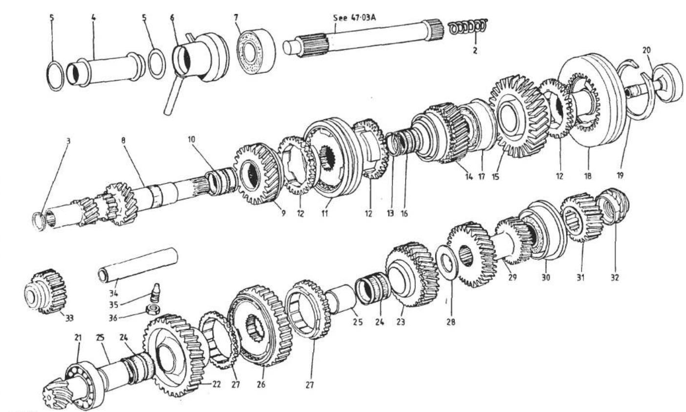
TURBO
4707A


| ILLUS NO. | DESCRIPTION |  PART NUMBER PART NUMBER | QUANTITY | MAY 1931REMARKS | |
| PRIOR C35 | C35 | ||||
| 47.07A | |||||
| 2 | Spring, Clutch Shaft Endthrust | A079F6067F | 1 | 1 | |
| 3 | Circlip, Clutch Shaft Retention | A079F6068F | 1 | 1 | |
| 4 | Support Tube, Clutch Release Bearing | A082F0754E | 1 | 1 | |
| 5 | 'O' Ring, Support Tube Sealing | A079F6096F | 2 | 2 | |
| 6 | Scroll and Housing | A079F4032K | 1 | 1 | |
| 7 | Ball Bearing, Primary Shaft Front | A079F6069F | 1 | 1 | |
| 8 | Primary Shaft | A079F6060F | 1 | 1 | |
| 9 | Drive Pinion, 3rd, Primary Shaft | A079F6064F | 1 | 1 | R/B A082F6317F |
| Drive Pinion, 3rd, Primary Shaft | A082F6317F | 1 | 1 | Supplied With Matched Synchro. Ring | |
| 10 | Needle Roller Bearing, 3rd Pinion | A079F6061F | 1 | R/B A082F6348F | |
| Needle Roller Bearing, 3rd Pinion | A082F6348F | 1 | |||
| 11 | Synchroniser Assembly, 3rd & 4th | A079F6072F | 1 | ||
| Synchroniser Assembly, 3rd & 4th | A082F6332F | 1 | |||
| 12 | Synchro Ring, 3rd, 4th & 5th | A079F6073F | 3 | 3 | |
| 13 | Stop Ring, 3rd & 4th Synchro 2.20 | A079F6074F | ) | ||
| Stop Ring, 3rd & 4th Synchro 2.25 | A079F6075F | ) | |||
| Stop Ring, 3rd & 4th Synchro 2.30 | A079F6076F | ) 1 | 1 | Selective | |
| Stop Ring, 3rd & 4th Synchro 2.35 | A079F6077F | ) | |||
| 14 | Drive Pinion, 4th, Primary Shaft | A079F6107F | 1 | 1 | |
| 15 | Drive Pinion, 5th, Primary Shaft | A079F6108F | 1 | 1 | |
| 16 | Needle Roller Bearing, 4th & 5th Pinion | A079F6109F | 2 | R/B A082F6349F | |
| Needle Roller Bearing, 4th & 5th Pinion | A082F6349F | 2 | |||
| 17 | Double Ball Bearing, Primary Shaft Rear | A079F6098F | 1 | R/B A082F6321F | |
| Double Ball Bearing, Primary Shaft Rear | A082F6321F | 1 | |||
| 18 | Synchroniser Assembly 5th | A079F6094F | 1 | ||
| Synchroniser Assembly, 5th | A082F6325F | 1 | |||
| 19 | Circlip, 5th Synchroniser | A079F6092F | 1 | 1 | |
| 20 | Screw, 5th Hub to Primary Shaft | A079F6097F | 1 | ||
| Screw, 5th Hub to Primary Shaft | A082F6322F | 1 | |||
| Oil Tube, 5th Hub Screw | A082F6323F | 1 | |||
| 21 | Roller Bearing, Secondary Shaft Front | A079F6116F | 1 | R/B A082F6334F | |
| Roller Bearing, Secondary Shaft Front | A082F6334F | 1 | |||
| d6pll | Turbo 47.07APage 1 | ||||

TURBO
47-07A


| ILLUSNO. | DESCRIPTION | PART NUMBER | QUANTITY | MAY 1991REMARKS | |
| PRIORC35 | C35 | ||||
| 47.06A | |||||
| Relay Dog, 5th Selector Shaft | A082F6341F | 1 | |||
| 18 | Selector Fork, 5th | A079F6163F | 1 | ||
| Selector Fork, 5th | A082F6335F | 1 | |||
| 19 | Selector Fork, 3rd & 4th | A079F6162F | 1 | 1 | |
| 20 | Selector Fork, 1st & 2nd | A079F6161F | 1 | 1 | |
| 21 | Locking Screw, Fork/Relay to Shaft | A079F6166F | 4 | 3 | |
| Locking Wire, Fork/Relay Screw | A079F6168F | 4 | 3 | ||
| Screw, 5th Fork to Shaft | A082F6337F | 1 | |||
| Spring Washer, 5th Fork Screw | A082F6336F | 1 | |||
| 22 | Setscrew, M9 x 25, Fork Clamping | A079F6221F | 4 | 4 | |
| 23 | Interlock Plunger, Short | A079F6174F | 2 | 2 | |
| 24 | Interlock Plunger, Long | A079F6173F | 1 | 1 | |
| 25 | Blanking Plug, 12mm Diameter | A079F6184F | 2 | 2 | |
| Blanking Plug, 17mm Diameter | A079F6183F | 1 | 1 | ||
| 26 | Detent Ball, Selector Shaft | A079F6176F | 4 | 4 | |
| 27 | Spring, Detent Ball | A079F6175F | 4 | ||
| Spring, Detent Ball | A082F6347F | 4 | |||

TURBO
47-07A


| ILLUS NO. | DESCRIPTION |  | QUANTITY | REMARKS | |
| PART NUMBER | PRIOR C35 | C35 | |||
| 47.15A | |||||
| 1 | Housing, Diff. Output Shaft, RH | A079F6275F | 1 | ||
| Housing, Diff. Output Shaft, RH | A082F6342F | 1 | |||
| Housing, Diff. Output Shaft, LH | A079F6276F | 1 | |||
| Housing, Diff. Output Shaft, LH | A082F6343F | 1 | |||
| 2 | Gasket, Output Shaft Housing | B079F6028F | 2 | 2 | |
| 3 | Drain Hose, Output Shaft Housing | A079F4019F | 2 | 2 | |
| 4 | Bolt, M7 x 20, Output Hsg./Trans. | A079F6218F | 1 | ||
| Bolt, M7 x 25, Output Hsg./Trans. | A079F6191F | 5 | 1 | ||
| Bolt, M7 x 70, Output Hsg./Trans. | A079F6287F | 2 | |||
| Bolt, M9 x 30, Output Hsg./Trans. | A079F6204F | 10 | 10 | ||
| Bolt, M9 x 75, Output Hsg./Trans. | A079F6286F | 2 | 4 | ||
| 5 | Shaft, Diff. Output, RH | A079F6281F | 1 | 1 | |
| Shaft, Diff. Output, LH | A079F6280F | 1 | 1 | ||
| 6 | Washer, Oil Retaining | A079F6282F | 2 | 2 | |
| 7 | Oil Seal, Output Shaft | A079F6288F | 2 | 2 | |
| 8 | Thrust Ring | A079F6283F | 2 | 2 | |
| 9 | Double Ball Bearing | A079F6277F | 2 | 2 | |
| 10 | Ring Nut, Bearing to Housing | A079F6278F | 2 | ||
| Ring Nut, Bearing to Housing | A082F6344F | 2 | |||
| 11 | Locking Screw, Ring Nut to Housing | A079F6279F | 2 | 2 | |
| 12 | Nut, Bearing to Output Shaft | A079F6284F | 2 | 2 | |
| 13 | Locking Screw, Output Shaft Nut | A079F6285F | 2 | 2 | |


| ILLUS NO. | DESCRIPTION |  | QUANTITY | MAY 1991 | |
| PART NUMBER | ALL | REMARKS | |||
| 60.01A | |||||
| 001 | Toolkit & Roll | B075T0728J | 1 | With Compomotive Wheels) | |
| Toolkit & Roll | A082T4003J | 1 | With BBS Wheels ) | ||
| 002 | Roll, Toolkit | A075T0369K | 1 | ) | |
| 006 | Spanner, O/E, 8 x 10 | B075T6003F | 1 | ) | |
| 007 | Spanner, O/E, 10 x 13 | B075T6004F | 1 | ) | |
| 008 | Spanner, O/E, 13 x 17 | B075T6005F | 1 | )'Roll' type | |
| 009 | Screwdriver, Posidrive no. 2 | B075T6006F | 1 | ) Toolkit | |
| 010 | Pliers | B075T6007F | 1 | ) | |
| 011 | 'T' Bar, Sliding | B075T6008F | 1 | ) | |
| 012 | Extension, 5 in., 3/8 in. Drive | B075T6009F | 1 | ) | |
| 013 | Spark Plug Socket, 13/16 in. | B075T6011F | 1 | ) | |
| 014 | Socket 19mm | B075T6010F | 1 | In Toolkit B075T0728J ) | |
| Socket, 17mm | B082T6001F | 1 | In Toolkit A082T4003J ) | ||
| 015 | Toolkit & Plastic Case | A082T4005F | 1 | > | |
| 016 | Strap, Tool Case Retention | A089U1412F | 1 | >Plastic Case type Toolkit | |
| 017 | Hook, Tool Case Strap | B082U4715K | 1 | > | |
| Rivet, Strap & Hook Fix | A075W6065Z | 3 | > | ||
| Washer, Rivet | A075W4013F | 3 | > | ||
| Jack, (Scissor Type) | B065T0347ZB | 1 | |||
| 020 | Jack, (With Integral Baseplate) | A085T4004K | 1 | ||
| 021 | Handle, 145mm Crank | B085T6002F | 1 | ||
| Handle, 265mm Crank | A075T0350F | 1 | |||
| 023 | Strap, Jack Retention, (Front) | A079U4033F | 1 | ||
| 024 | Strap, Jack Retention, (Rear) | A082U5024F | 1 | ||
| 025 | Anchor Hook, Jack Strap | B082U4715K | 2 | ||
| Pop Rivet, Strap and Anchor Fixing | A075W6099F | 6 | |||
| 026 | Clip, Jack Handle Stowage (2 Hole Fix) | A079W6146F | 2/3 | ) | |
| Clip, Jack Handle Stowage (1 Hole Fix) | A079W6145F | 1 | ) As Fitted | ||
| Turbo 60.01A | |||||
| d6p17 | |||||

TURBO
60·02A


| ILLUS NO. | DESCRIPTION |  PART NUMBER PART NUMBER | QUANTITY | REMARKS | |
| ALL | |||||
| 60.02A | |||||
| Engine Special Tool Kit Assembly | T000L0002A | 1 | Comprises * Items | ||
| 1 | Cylinder Liner Clamps* | T000T0002A | 2 | ||
| 2 | Cylinder Liner Extractor* | T000T0012A | 1 | ||
| 3 | Cylinder Liner Nip Gauge* | T000G0003A | 1 | ||
| 4 | Drift, Inlet Valve Seat* | T000T0093A | 1 | ||
| 5 | Drift, Exhaust Valve Seat* | T000T0094A | 1 | ||
| 6 | Inserter, Spigot Bearing* | T000T0242A | 1 | ||
| 7 | Drift, Valve Guide* | T000T0004A | 1 | ||
| 8 | Inserter, Camshaft Oil Seal* | T000T0010A | 1 | ||
| 9 | Spanner, Oil Pick-Up Pipe Union* | T000T0083A | 1 | ||
| 10 | Extractor, Camshaft Oil Seal* | T000T0011A | 1 | ||
| 11 | Sleeve, Camshaft Oil Seal* | T000T0072A | 1 | ||
| 12 | Pilot, Rear Oil Seal, Crankshaft* | T000T0084A | 1 | ||
| 13 | Puller, Crankshaft Pulley* | T000T0170A | 1 | ||
| 14 | Pilot, Front Cover* | T000T0009B | 1 | ||
| Clips, Tool Retention, set c/w Fixings | T000L0005A | 1 | |||
| Shadow Sheet, Self Adhesive | T000T0271A | 1 | |||
| Tool Board | T000T0270A | 1 | |||
| Burroughs Gauge, Toothed Belt | T000T0290A | 1 | R/B T000G0025J | ||
| Burroughs Gauge, Toothed Belt | T000G0025J | 1 | Cantilevered Type | ||
| Torx Socket, Cam Housing Bolt | T000T0443A | 1 | |||
| Carburettor Balance Adaptors | T000T0496F | 4 | |||
| Carburettor Float Setting Bar | T000T0498F | 1 | |||
| Carburettor Manometer | T000T0499M/F | 1 | M-With Mercury, F-Without Mercury | ||
| Rear Brake Caliper Spreader | T000T0556F | 1 | 1985 Model Year | ||
| Screen Removal Tool | A075B6169F | 1 | |||
| Turbo 60.02A | |||||
| d6pl8 | |||||
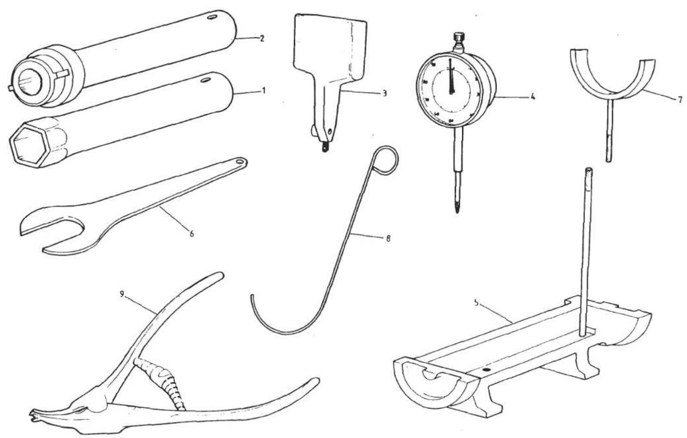
TURBO 60-04A


LOTUS PAINT CODES & TOUCH-IN PAINT/STICK NUMBERS
| LOTUS PAINT CODE | COLOUR | LOTUS TOUCH-IN PAINT NO. | LOTUS PAINT CODE | LOTUS TOUCH-IN PAINT NO. | |
| A02 | Black | B036B6424S | A53 | Cirrus Grey | A082B6127F |
| A03 | Silver Diamond | A075B6249F | A54 | New Jupiter Red | A082B6128F |
| A04 | Gold | A075B6250F | A55 | Cherry Red | A082B6129F |
| A05 | Viper Green | A075B6271F | A56 | Nimbus Grey | A082B6130F |
| A06 | Bermuda Blue | A075B6251F | A57 | Shadow Grey | A082B6131F |
| A07 | Roman Bronze | A075B6255F | A58 | Champagne Gold | A082B6132F |
| A08 | Lotus Bronze | A075B6256F | A59 | Steel Blue * | C082B6133J |
| A13 | Tabac | A083B6252F | A60 | Seal Grey | A082B6144F |
| A14 | Altair Green | A083B6253F | A61 | Atlantic Green | A082B6134F |
| A15 | Helleblau | A083B6254F | A62 | Claret * | C082B6145J |
| A16 | Essex Blue | A082B6060F | A63 | British Racing Green '88 MY | B082B6146S |
| A17 | Essex Blue | A082B6062F | A64 | Camel Yellow | A082B6192F |
| A19 | Copper Fire Metallic | A082B6063F | A65 | British Racing Green '89 MY | B082B6171S |
| A21 | Monaco White | B050B6237S | A67 | Vulcan Grey * | C082B6172J |
| A22 | Lotus Yellow II | A075B6267F | A68 | Pacific Blue * | C082B6173J |
| A23 | Calypso Red | B075B6264S | |||
| A25 | New Gold | A076B6157F | |||
| A26 | Copper | A082B6063F | |||
| A30 | Jupiter Red | A076B6158F | |||
| A31 | Copper | A076B6159F | |||
| A32 | Mediterranean Blue * | C082B6126J | |||
| A33 | Ice Blue | A082B6143F | |||
| A34 | Essex Blue | A076B6161F | |||
| A35 | Silver | A076B6162F | |||
| A36 | New Gold | A076B6163F | |||
| A38 | Chrysler Steel Grey | A089B6164F | |||
| A42 | British Racing Green * | C082B6089J | |||
| A44 | Glacier Blue * | C082B6090J | |||
| A45 | Silver Frost * | C082B6091J | |||
| A51 | Midnight Blue | A082B6125F | |||
| A52 | Mediterranean Blue | A082B6126F | Touch-In Stick Display Unit | A082B6191S |
* TOUCH-IN KIT, CONTAINING (PAINT/LACQUER STICKS)
| ILLUS NO. | DESCRIPTION |  PART NUMBER PART NUMBER | QUANTITY | REMARKS | |
| ALL | |||||
| 60.04A | |||||
| 1 | Transmission Tool Kit, Comprises | T000L0621A | 1 | 1st/2nd gear | |
| 2 | Spanner, Bearing to Shaft Nut | T000T0612F | 1 | ||
| 3 | Spanner, Bearing to Housing Lock Ring | T000T0613F | 1 | ||
| 4 | Dial Gauge Support | T000T0614F | 1 | ||
| 5 | Dial Gauge | T000T0615F | 1 | ||
| 6 | Pinion Setting Fixture | T000T0616F | 1 | ||
| 7 | Spanner, Speedo Drive Nut | T000T0617F | 1 | ||
| 8 | Syncro Gauges (set of 6) | T000T0618F | 1 | ||
| 9 | Reverse Selector Gauge | T000T0619F | 1 | ||
| Circlip Pliers, 3rd/4th Syncro Hub | T000T0620F | 1 | |||
| FEB 1987 | Turbo 60.04A | ||||
| d6p19 | |||||
- SERVICE NOTES
- CONTENTS
- VEHICLE IDENTIFICATION NUMBER
- NOTES
- USA
- TECHNICAL DATA
- SECTION TD A - ENGINE TYPE 907/912
- PAGE
- VALVE GUIDES
- CAMSHAFTS
- CAM FOLLOWERS
- AUXILIARY SHAFT
- CRANKSHAFT
- SECTION TD A
- CONNECTING ROD
- GUDGEON (PISTON) PIN
- PISTON AND LINER
- PISTON (CONT.)
- IGNITION SYSTEM
- DISTRIBUTOR
- SECTION TD B
- SECTION TD B - ENGINE TYPE 910
- MARKET
- ENGINE EQUIPMENT
- WET SUMP INTRODUCTION
- CYLINDER HEAD
- VALVE SPRINGS
- FLYWHEEL
- GUDGEON PIN
- LUBRICATION SYSTEM
- SECTION TD D - VEHICLE, ESPRIT S3 & TURBO
- CAPACITIES
- SUSPENSION
- STEERING
- BRAKES
- WHEELS & TYRES
- 15" TYRE REPLACEMENT
- TORQUE SETTINGS
- BA 1 - PAINT CODES
- ICI PAINT REFERENCE NUMBER
- BA 2 - ESSENTIAL WORKING PRACTICE
- CAUTION
- BA 3 - BODY AND COMPONENT PREPARATION FOR PRIMER COATING
- BA 4 - BODY AND COMPONENT POLYURETHANE PRIMER
- SECTION BA
- BA 5 - BODY & COMPONENT PREPARATION FOR COLOUR COATING
- BA 6 - BODY & COMPONENT NITRO-CELLULOSE COLOUR COAT
- BA 8 - P422 LINE 2 PACK ACRYLIC POLYURETHANE SPRAYING
- BA 9 BODY & COMPONENT INTERCOAT RECTIFICATION PROCEDURES
- BA 10 - NITRO-CELLULOSE PAINT RECTIFICATION
- GEL CRACKS CONT
- BLISTERS
- CHIPS AND SCRATCHES
- EDGE/CORNER CHIPS
- PANEL CHIPS
- SCRATCHES-MINOR
- SCRATCHES-MAJOR
- BA 11 - ACRYLIC POLYURETHANE PAINT RECTIFICATION
- BA 12 - PAINT PROCEDURE FOR RRIM COMPONENTS
- PREPARATION
- COLOUR PAINT APPLICATION
- CLEAR COAT APPLICATION. (NOT USED ON 'L' PAINT CODE CARS)
- BA13 - PEARLESCENT WHITE PAINT PROCEDURE
- RRIM COMPONENTS IN PEARLESCENT WHITE
- BB 1 - LOTUS COMPOSITE BODY FEATURES
- SECTION BB
- BB 2 - BODYCARE
- (OWNERS HANDBOOK EXTRACT)
- WASHING
- POLISHING
- VENTILATION
- SUMMARY
- WINDSCREEN
- BRIGHT METAL
- ALLOY WHEELS
- UPHOLSTERY AND ROOF LINING
- LEATHER UPHOLSTERY
- SEAT BELTS CLEANING
- BB 3 - GENERAL DESCRIPTION
- BB 4 - ACCIDENT DAMAGE ASSESSMENT
- BB 7 - HEADLAMP BOWLS AND SURROUNDS
- BB 11 - REPLACEMENT SECTIONS
- BB 12 - POSITIONING REPLACEMENT PANELS
- BOBBINS PULLING OUT
- STRIPPED THREADS
- LAMINATING NEW BOBBIN
- LAYUP AROUND BOBBINS
- BB 14 - BODY MOUNTING POINTS
- EXCEL
- ESPRIT
- BD.1 - WINDSCREEN REPLACEMENT
- SECTION BD
- BD.3. - REAR BULKHEAD GLASS
- TO REPLACE GLASS
- TO REPLACE
- BD.5. - DOOR WINDOW FRAME
- BD.7. - DOOR GLASS EXTERNAL WEATHERSTRIP
- BD.8. - DOOR QUARTER LIGHT GLASS
- ADJUSTMENT
- BD.11 - FRONT BONNET PANEL
- BD.12. - TAILGATE
- LATCH ADJUSTMENT
- TURBO
- BD.17 - GLASS ROOF ABUTMENT
- GENERAL DESCRIPTION
- KEY TO FRONT SUSPENSION GENERAL LAYOUT DRAWING
- CB.1.- LUBRICATION
- CB.2.- GEOMETRY
- CB.3.-CASTOR ADJUSTMENT
- CB.4.-FRONT WHEEL ALIGNMENT
- CB.5.- FRONT SUSPENSION DISASSEMBLY
- CB.6.-FRONT HUB ADJUSTMENT
- CB.7. - WHEEL BEARING REPLACEMENT
- FRONT SUSPENSION
- KEY TO SUSPENSION LAYOUT DIAGRAM
- GEOMETRY
- CASTOR ADJUSTMENT
- SUSPENSION DISASSEMBLY
- SUSPENSION RE-ASSEMBLY
- FRONT WHEEL BEARINGS
- REAR SUSPENSION
- SECTION DB - ESPRIT S3 & TURBO
- KEY TO REAR SUSPENSION GENERAL LAYOUT DRAWING
- DB.1.- GEOMETRY
- DB.2.- REAR WHEEL ALIGNMENT
- DB.3.- REAR SUSPENSION REASSEMBLY
- DB.4. - REAR WHEEL BEARING REMOVAL
- DB.5.- REAR WHEEL BEARING INSTALLATION
- DB.6. - DRIVE SHAFT C.V. JOINT BOOT REPLACEMENT
- EA.1.-LUBRICATION
- GENERAL
- OIL LEVEL
- OIL FILTER
- EA.2.- ENGINE TUNE (NOT FEDERAL TURBO)
- EA.3. - COMPRESSION CHECK
- EA.5.- CAMSHAFTS
- TO REMOVE
- SECTION EA
- EA.6.-VALVE CLEARANCES
- TO CHECK
- TO ADJUST
- EA.7. - TOOTHED BELT GUARD (FRONT ENGINED CARS - EARLY TYPE)
- UPPER SECTION
- LOWER SECTION
- EA.8.- CAMSHAFT DRIVING BELT (TOOTHED BELT)
- EA.9. - DRIVING BELT TENSIONER
- EA.10.-CYLINDER HEAD
- TO REMOVE (NATURALLY ASPIRATED)
- 912 HEAD GASKET SELECTION
- EA.12.-DECARBONISE CYLINDER HEAD & PISTONS
- EA.13.-VALVE SEAT INSERTS
- EA.14.-VALVE GUIDES
- EXCEL MODELS - 1985 MODEL YEAR ONWARD
- EA.20.-IGNITION DISTRIBUTOR
- EA.21.-OIL PUMP & AUXILIARY HOUSING
- EA.22.-INLET MANIFOLD & CARBURETTORS
- TO REMOVE (ESPRIT TURBO)
- EA.25. - ENGINE ASSEMBLY
- NOTE
- TOFIT HEATSHIELD
- EA.26. - FLYWHEEL & RING GEAR (MANUAL TRANSMISSION)
- EA.27. - CRANKSHAFT REAR OIL SEAL
- OVERSIZE OUTSIDE DIAMETER MAIN BEARING SHELLS
- 907 ENGINES
- 912 AND 910 WET SUMP ENGINES
- 910 DRY SUMP ENGINE
- MODIFICATION OF 910/912 MAIN BEARING PANEL, PRIOR TO ENG. NO 20875
- EA.30.- CONNECTION OF OIL COOLER THERMOSTAT
- EA.31.-LUBRICATION SYSTEM PRECAUTIONS
- ENGINE MANAGEMENT
- FUEL PRESSURE SOLENOID
- THROTTLE JACK SOLENOID
- AIR PUMP & DIVERTOR VALVE
- EVAPORATIVE CONTROL SYSTEM
- SECTION EMA
- COLD ENGINE
- EMA.3.- ENGINE DIAGNOSTIC PROCEDURE
- SUB GROUP E - FUEL CONTROL PRESSURE
- SUB GROUP H - THERMAL SWITCH
- SUB SECTION I - FUEL PUMP ELECTRICAL CIRCUIT
- CHECK SAFETY INERTIA SWITCH HAS NOT BEEN ACTIVATED
- EMC.2. - THERMAL IGNITION ADVANCE
- VACUUM CIRCUITS
- WATER TEMP: INLET MANIFOLD BELOW 60°C
- SECTION EMC
- EMC.3. - CRANKCASE BREATHER VALVE
- EMC.4. - COLD ENRICHMENT THERMAL VALVE
- EMC.5. - PLENUM PURGE
- EMC.6. - THROTTLE JACK SOLENOID
- EMC.7. - OVERBOOST SWITCH
- EMC.8. IDLE SPEED & IGNITION TIMING SETTING PROCEDURE
- EMD.2. - THERMAL IGNITION ADVANCE
- EMD.3. - CRANKCASE BREATHER VALVE
- EMD.4. - COLD ENRICHMENT THERMAL VALVE
- EMD.5. - PLENUM PURGE
- EMD.6. - THROTTLE JACK SOLENOID
- EMD.7. - AIR INLET TEMPERATURE CONTROL SYSTEM
- SECTION EMD
- GEARBOX/TRANSMISSION
- SECTION FB - ESPRIT
- KEY TO TRANSMISSION ASSEMBLY DRAWING
- C35' INTRODUCTION
- DRAIN AND LEVEL PLUG
- FB.1. - GEARSHIFT LEVER AND GEAR CHANGE LINKAGE
- KEY TO GEARCHANGE LINKAGE DRAWING
- TUBE LINKAGE BASIC SETTING
- CROSSGATE CABLE BASIC SETTING
- FB.2. - TRANSMISSION ASSEMBLY
- SECTION FB
- FB.3. - CLUTCH BELLHOUSING
- DISMANTLING
- FB.4.- CLUTCH SHAFT
- FB.6.-GEAR SELECTORS REMOVAL
- REVERSE GEAR SELECTOR
- 5TH GEAR SELECTOR
- 3RD AND 4TH GEAR SELECTOR
- 1ST AND 2ND GEAR SELECTOR
- INTERLOCK PLUNGERS
- FB.7. - GEAR SELECTOR REPLACEMENT
- GEAR SELECTOR MECHANISM
- 4TH GEAR STOP ADJUSTMENT
- FINAL ASSEMBLY
- FB.8.-PRIMARY SHAFT
- KEY TO GEARBOX SHAFTS & GEARS DRAWING
- FB.9.-BEVEL PINION SHAFT
- ADJUSTMENTS
- FINAL REPLACEMENT
- FB.10.- DIFFERENTIAL SHAFTS (DRIVE SHAFTS)
- DISMANTLE
- TO ASSEMBLE
- FB.11.- DIFFERENTIAL CROWNWHEEL & PINION
- FB.12.- DIFFERENTIAL BEARINGS ADJUSTMENT
- METHOD 1
- METHOD 2
- FB.13. - BACKLASH ADJUSTMENT
- NON-S.I.R. TYPE UPPER STEERING COLUMN
- S.I.R. TYPE UPPER STEERING COLUMN
- KEY TO INTERMEDIATE COLUMN & RACK & PINION ASSEMBLY DRAWING
- HB.1 - GENERAL DESCRIPTION
- HB.3 - UPPER STEERING COLUMN ASSEMBLY
- POST ACCIDENT INSPECTION
- S.I.R. CARS
- TO REFIT UPPER STEERING COLUMN ASSEMBLY: NON-S.I.R. CARS
- HB.4 - INTERMEDIATE STEERING COLUMN ASSEMBLY
- HB.5 - TRACK ROD ENDS & TOE-IN ADJUSTMENT
- HB.6 - STEERING RACK GAITERS
- TO FIT GAITER KIT
- HB.7 - RACK & PINION ASSEMBLY
- TO REMOVE RACK & PINION ASSEMBLY
- TO REFIT RACK & PINION ASSEMBLY
- JB.1 - FRONT BRAKE PAD REPLACEMENT
- SECTION JB
- JB.2 - REAR BRAKE PAD REPLACEMENT
- JB. 3 - HANDBRAKE
- JB. 4 - FRONT BRAKE CALIPER OVERHAUL
- JB. 5 - REAR CALIPER OVERHAUL
- JB.7 - MASTER CYLINDER
- TO OVERHAUL
- JB. 8 - BRAKE SERVO UNIT
- SECTION JC - ESPRIT S3 & TURBO: 1985 MODEL YEAR ONWARDS
- JC.1 - FRONT BRAKE PAD REPLACEMENT
- TO REMOVE PADS
- SECTION JC
- JC 3. - HANDBRAKE ADJUSTMENT
- PAGE 6
- JC.4 - FRONT CALIPER OVERHAUL
- JC. 5 - REAR CALIPER OVERHAUL
- PAGE 8
- REPLACEMENT
- JC.6-BRAKE DISCS
- JC. 7 - BRAKE SERVO UNIT
- JC. 8 - MASTER CYLINDER OVERHAUL
- COOLING SYSTEM
- KB.1 - GENERAL DESCRIPTION
- KB.2 - DRAIN/REFILL PROCEDURE
- KB.4 - COOLING FANS THERMAL TRIP
- SECTION KB
- KB.6 - REPLACEMENT OF EARLY TYPE RAD. DUCT STAYS
- FUEL SYSTEM
- LA.1.-GENERAL DESCRIPTION
- ESPRIT SERIES 3
- LA.2. - CARBURETTOR THEORY OF OPERATION
- FUEL SUPPLY
- STARTING
- IDLING
- PROGRESSION
- ACCELERATION
- FULL THROTTLE
- LA.3. - FLOAT LEVEL CHECKING
- LA.4. - CARBURETTOR BALANCING PROCEDURE
- LA.5.-CARBURETTOR MOUNTING
- SECTION LA
- KEY TO FUEL SYSTEM DIAGRAM
- SECTION LB - ESPRIT TURBO, DOM/ROW
- LB.1.-GENERAL DESCRIPTION
- SECTION LB
- LB.3. - FLOAT LEVEL CHECKING
- LB.4.- CARBURETTOR BALANCING PROCEDURE
- LB.5.-CARBURETTOR MOUNTING
- LC.1 - GENERAL DESCRIPTION
- LC.2 - CARBURETTOR THEORY OF OPERATION
- SECTION LC
- POWER JET OPERATION
- LC.3 - FUEL CONTROL PRESSURE
- LC.4 - FLOAT LEVEL CHECKING
- LC.5 - CARBURETTOR BALANCING PROCEDURE
- LC.6 - CARBURETTOR MOUNTING
- FUNCTION INJECTION COMPONENT FUNCTION
- LD.1.-GENERAL DESCRIPTION
- FUEL INJECTION SYSTEM DESCRIPTION
- FUEL FEED
- ELECTRIC FUEL PUMP
- FUEL FILTER
- MIXTURE CONTROL UNIT
- FUEL INJECTORS
- MIXTURE ADAPTATION
- COLD START INJECTOR
- THERMAL TIME SWITCH
- AUXILIARY AIR VALVE
- LD.10 - WARM UP REGULATOR
- HIGH ALTITUDE COMPENSATION
- EXHAUST EMISSION CONTROL
- LAMBDA SENSOR
- FREQUENCY VALVE (TIMING VALVE)
- ELECTRONIC CONTROL UNIT (E.C.U.)
- FUEL BY-PASS VALVE
- VACUUM OPERATED ENGINE MANAGEMENT DEVICES
- THERMAL IGNITION VALVE (T.I.V.)
- IGNITION SOLENOID & THROTTLE JACKING CAPSULE (T.J.C.)
- AIR CONDITIONING IDLE UP SOLENOID
- EVAPORATIVE LOSS SYSTEM
- CHARCOAL CANISTER
- ENGINE WARM UP SUMMARY
- ENGINE CRANKING
- LD 22 - FUEL SYSTEM PRECAUTIONS
- LD 23 ENGINE MANAGEMENT SYSTEM CHECK/SET UP PROCEDURE
- TOOLS REQUIRED
- LD 24 - FUEL INJECTION FAULT DIAGNOSIS
- SYMPTOM
- POSSIBLE CAUSE
- A - FUEL PUMPS
- B - FUEL PRESSURES
- CHECK PRIMARY PRESSURE
- CHECK SUPPLY PRESSURE TO FUEL DISTRIBUTOR
- ADJUST PRIMARY PRESSURE REGULATOR
- CHECK COLD CONTROL PRESSURE
- CHECK WARM CONTROL PRESSURE
- CHECK FOR FUEL SYSTEM LEAKS, INTERNAL & EXTERNAL
- C - AUXILIARY AIR VALVE
- COLD TEST
- HOT TEST
- D - COLD START INJECTOR
- E - SENSOR PLATE
- F - VACUUM SUPPLY
- G - FUEL INJECTORS
- REFITTING FUEL INJECTORS
- H - BASIC MIXTURE ADJUSTMENT
- I - THROTTLE DOES NOT OPEN COMPLETELY
- J - THERMO-TIME SWITCH
- L - FUEL BY-PASS VALVE
- M - THROTTLE JACKING CAPSULE
- N - THROTTLE POSITION SWITCH
- O - AIR LEAKS IN EXHAUST/INLET
- P - THROTTLE IMBALANCE
- ELECTRICAL COMPONENT FUNCTION & FAULT DIAGNOSIS
- IDLE CHANGE OVER RELAY
- FUEL BY-PASS CONTROL RELAY
- HIGH TEMPERATURE SWITCH
- IDLE UP SOLENOID
- R.P.M. RELAY
- IGNITION SOLENOID
- LOW TEMPERATURE SWITCH
- WARM UP REGULATOR
- THROTTLE POSITION SWITCH
- FREQUENCY VALVE
- ELECTRONIC CONTROL UNIT
- FUEL PUMPS
- INERTIA SWITCH
- ELECTRICAL
- MB.4.- LUMENITION IGNITION SYSTEM
- IDENTIFICATION - POWER MODULE
- OPTICAL SWITCH
- CONNECTOR BLOCKS
- TESTING INSTRUCTIONS FOR "LUMENITION" MK 16 AND MK 17 IGNITION SYSTEMS
- TO TEST THE OPTICAL SWITCH
- DO NOT LEAVE THE IGNITION ON FOR A LONG TIME (MAX 15 MINS) WITH THE OPTICAL SWITCH ASSEMBLY DISCONNECTED
- MB.5. - LUCAS CONSTANT ENERGY IGNITION
- RECOMMENDED TEST EQUIPMENT
- MB.6.- 'MAINTENANCE FREE' BATTERY CHARGING PROCEDURE
- MB.7. - DIM-DIP HEADLAMP SYSTEM (U.K. MODELS)
- COMPONENT LOCATION
- SECTION MC
- COMPONENT INDEX
- LEGEND
- ENGINE MANAGEMENT OPERATION
- ULSAFE ALARM COMPONENT LOCATION
- INSTRUMENT BINNACLE REMOVAL
- LUCAS CONSTANT ENERGY IGNITION
- BATTERY RE-CHARGING PROCEDURE
- SHEET / PAGE
- SECTION ME
- SHEET/PAG
- RECOMMENDED LUBRICANTS
- ENGINE
- BODYWORK DEFECTS SHEET
- ROAD TEST
- FIRST AFTER SALES SERVICE
- EXCEL —— ESPRIT S3 —— ESPRIT TURBO
- MAINTENANCE NOTES
- ROAD TEST PERFORMANCE
- MAINTENANCE PLAN (NOT USA)
- SECTION OC
- TRANSMISSION
- SAE 80
- API GL5
- MAINTENANCE SCHEDULE EXCEPT CALIFORNIA
- MAINTENANCE SCHEDULE EXCEPT CALIFORNIA -CONTINUED
- MAINTENANCE SCHEDULE CALIFORNIA
- RECOMMENDED MAINTENANCE X
- REQUIRED ENGINE MAINTENANCE ●
- MAINTENANCE SCHEDULE CALIFORNIA -CONTINUED
- HEATER/AIR CONDITIONING
- PB.1 - AIR CONDITIONING OPERATING PRINCIPLES
- CONDENSER
- RECEIVER-DRIER
- EXPANSION VALVE
- TEMPERATURE CONTROL SWITCH
- PB2 - AIRFLOW DISTRIBUTION
- OFF
- NORM/VENT
- INTERIOR/HEATER
- DEFROST
- PB.3 - REFRIGERANT HANDLING
- PB.4 - REFRIGERANT PIPEWORK PRECAUTIONS
- PB.5 - CHARGING UNIT WITH REFRIGERANT
- PB.6 - REFRIGERANT QUICK-CHECK PROCEDURE
- PB.7 - RECOMMENDED REFRIGERANT OIL
- PB.8 - REFRIGERANT OIL LEVEL CHECKING PROCEDURE
- PB.9-COMPRESSOR
- FITTING A NEW COMPRESSOR
- KEY TO CLUTCH SYSTEM DRAWING
- QB 1 - ADJUSTMENT
- 1 PEDAL
- RELEASE FORK
- SECTION QB
- QB 2 - HYDRAULIC UNITS
- QB 3 - CLUTCH ASSEMBLY
- QB.4 - RELEASE BEARING
- QB 6 - CLUTCH SHAFT
- INTERIOR TRIM
- SECTION VB - ESPRIT S3 & TURBO
- VB.1. - CENTRE CONSOLE
- VB.2. - TUNNEL SIDES
- VB.3. - INSTRUMENT BINNACLE
- U.S.A (FEDERAL) MODELS
- VB.5. - CANT RAILS
- VB.6. - 'A' POST COVERS
- VB.7. - WINDSCREEN HEADER RAIL
- VB.8 - REAR BULKHEAD TRIM
- TURBO ESPRIT
- SERVICE PARTS LIST
- 1980-87 MODEL YEARS
- LOTUS CARS LIMITED
- PART NUMBERS
- STANDARD HARDWARE PART NUMBERS
- ENGINE PART NUMBERS
- INTRODUCTION OF TYPE C35 GEARBOX ASSEMBLY
- DRAIN PLUG
- LEVEL PLUG
- EXHAUST SILENCER MOUNTING BRACKET
Brand : Lotus
Model : Turbo Esprit (1980)
Category : Automobile