ECO 210-5 - Uncategorized Senseca - Free user manual and instructions
Find the device manual for free ECO 210-5 Senseca in PDF.


| Product Type | Environmental Data Logger |
| Brand | Senseca |
| Model | ECO 210-5 |
| Dimensions (approx.) | 100 x 50 x 20 mm |
| Weight (approx.) | 100 g |
| Power Supply | 2 x AAA batteries (not included) |
| Battery Life | Up to 6 months with normal use |
| Measurement Range (Temperature) | -20°C to 60°C |
| Accuracy (Temperature) | ±0.5°C |
| Measurement Range (Humidity) | 0% to 100% RH |
| Accuracy (Humidity) | ±3% RH |
| Logging Interval | Adjustable from 1 minute to 24 hours |
| Memory Capacity | Up to 100,000 data points |
| Connectivity | USB 2.0 for data download |
| Display | LCD with current readings and status |
| Software Compatibility | Windows and macOS (Senseca Logger Suite) |
| Ingress Protection | IP54 (dust and splash resistant) |
| Operating Conditions | Indoor use, 0°C to 50°C, non-condensing |
| Maintenance | Clean with soft dry cloth; do not use solvents |
| Safety Precautions | Do not immerse in water; keep away from heat sources |
| Spare Parts & Repairability | Battery compartment accessible; no user-serviceable parts inside |
| Included Accessories | USB cable, quick start guide, mounting bracket |
Frequently Asked Questions - ECO 210-5 Senseca
User questions about ECO 210-5 Senseca
0 question about this device. Answer the ones you know or ask your own.
Ask a new question about this device
Download the instructions for your Uncategorized in PDF format for free! Find your manual ECO 210-5 - Senseca and take your electronic device back in hand. On this page are published all the documents necessary for the use of your device. ECO 210-5 by Senseca.
USER MANUAL ECO 210-5 Senseca
Picture shows ECO 210-3 with UT
Table of contents
1 About this documentation ....4
1.1 Foreword....4
1.2 Legal notices....4
1.3 Further information....4
2 Safety 5
2.1 Foreseeable misuse....5
2.2 Safety instructions....6
2.3 Intended use 6
2.4 Qualified personnel....6
3 The product at a glance....7
3.1 Display elements....7
3.2 Connections....7
3.3 Operating elements 8
4 Operation 9
4.1 Opening the configuration menu....9
4.2 Open the adjustment menu 11
5 Measurement Basics....12
5.1 Special functions 12
5.1.1 NVLL Tare function.... 12
5.1.2 F,NE High-resolution measurement with 0.1 Pa (ECO 210-3) or 1 Pa (ECO 210-5) 12
5.1.3 AVR 0:02 / AVR 0:05 / AVR 0: 10.... 13
5.2 Pressure Connection.... 14
5.2.1 Replacement of pressure hoses.... 14
6 Operation and maintenance....16
6.1 Operating and maintenance notices 16
6.2 Battery 16
6.2.1 Battery indicator 16
7 Disposal....18
8 Error and system messages....19
9 Technical data....20
10 Service 22
10.1 Manufacturer 22
10.2 Calibration and adjustment service.... 22
1 About this documentation
1.1 Foreword
Read this document carefully and familiarize yourself with the operation of the product before you use it. Keep this document ready to hand and in the immediate vicinity of the product so that it is available to the personnel/user for reference at all times in case of doubt.
The user must have carefully read and understood the operating manual before beginning any work.
1.2 Legal notices
The liability and warranty of the manufacturer for damages and consequential damages are voided with misuse, disregarding this document, disregarding safety notices, assignment of inadequately qualified technical personnel and arbitrary modifications of the product.
This document is entrusted to the recipient for personal use only. Any impermissible transfer, duplication, translation into other languages or excerpts from this operating manual are prohibited.
The manufacturer assumes no liability for print errors.
1.3 Further information
Software version of the product:
- V1.1 or later
For the exact product name, refer to the type plate on the rear side of the product.
Note
For information about the software version, press and hold the ON button to switch on for longer than 5 seconds. The series is shown in the main display and the software version of the product is shown in the secondary display.
2 Safety
Danger
This symbol warns of imminent danger, which can result in death, severe bodily injury, or severe property damage in case of non-observance.
Caution
This symbol warns of potential dangers or harmful situations, which can cause damage to the device or to the environment in case of non-observance.
Note
Blue underlining indicates processes, which can have a direct influence on operation or can trigger an unforeseen reaction in case of non-observance.
2.1 Foreseeable misuse
The fault-free function and operational safety of the product can only be guaran-teed if applicable safety precautions and the device-specific safety instructions for this document are observed.
If these notices are disregarded, personal injury or death, as well as property damage can occur.
⚠️ Danger Incorrect area of application!
In order to prevent erratic behavior of the product, personal injury and property damage, the product must be used exclusively as described in the chapter De-scription in the operating manual.
▶ The product is not suitable for use in explosion-prone areas!
▶ The product must not be used for diagnostic or other medical purposes on patients!
For measurements requiring devices that are subject to authorization or special approvals, this product is not a substitute for such products and can only be used as an aid in preparatory or comparison measurements!
▶ Do not use in safety / emergency stop devices!
▶ Not for unattended operation on other pressure vessels/systems, especially if leaks, etc. hazards can arise.
2.2 Safety instructions
Note
This product does not belong in children's hands!
2.3 Intended use
| ECO 210-3 | The device is designed as a manometer and measures even the smallest pressure differential pressures of up to ±200 hPa with a maximum resolution of up to 0.1 Pa (at RANG = Slo and FVNC = FINE) in air or in non-corrosive/non-ionising gases between the two pressure connections. |
| ÉCO 210-5 | The device is designed as a manometer and measures even the smallest pressure differential pressures of up to ±2000 hPa with a maximum resolution of up to 1 Pa (at RANG = Slo and FVNC = FINE) in air or in non-corrosive/non-ionising gases between the two pressure connections. |
Usual applications include precise measurements of filter condition, gas flow pressure, draught, leak integrity, dynamic pressure flow speed.
The pressure connection is made at the supplied interchangeable pressure connection ports with suitable hoses - 4 different connection options are available as standard, many other connection options can be used easily and reliable with G 1/8 adapters.
The product must only be used under the conditions and for the purposes for which it was designed.
It must be handled with care and used according to the technical data (do not throw, strike, etc.). Suitable measures must be used to protect the pressure connections and be protected from dirt and moisture.
2.4 Qualified personnel
For commissioning, operation and maintenance, the relevant personnel must have adequate knowledge of the measuring process and the significance of the measurements. The instructions in this document must be understood, observed and followed.
In order to avoid any risks arising from interpretation of the measurements in the concrete application, the user must have additional expertise. The user is solely liable for damages/danger resulting from misinterpretation due to inadequate expertise.
3 The product at a glance
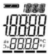
LCD Display+
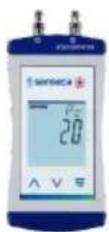
Front view
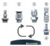
Connection variants
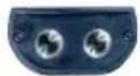
Top view
3.1 Display elements


Battery indicator
Unit display
Main display
Auxiliary display
Bar graph
Evaluation of the battery status
Display of the units or Min/Max/Hold information text
Measurement of the current pressure or value for min/max/hold
Measurement of the current pressure in Min/Max/Hold mode
Trend display with the special function F,NE
3.2 Connections
Universal connection
Interchangeable pressure connection via G1/8" thread.
3.3 Operating elements

On / Off button
Press briefly
Switch on the device
Activate / deactivate lighting
Long press
Switch off the device

Reject changes in a menu

Up / Down button

Press briefly

Display of the min/max value

Change value of the selected parameter
Long press

Reset the min/max value of the current measurement
Both simultaneously
Rotate display, overhead display


Function button
Press briefly

Freeze measurement (Hold)

Call up next parameter
Long press, 2s

Start menu "configuration", (ONF appears in the display
Long press, 4s

Depending on the selected special function:
Activation of the Tare function NVLL, high-resolution measurement F,NE or rapid measurement with mean value AVR
Operating status

device is in measured value display

device is in the configuration menu
4 Operation
4.1 Opening the configuration menu
1 Press the Function key for 2 seconds to open the Configuration menu.
2 (ONF appears in the display. Release the Function key.
| Parameter Values Meaning | ||
| UN,T | Display unit | |
| Pa | (only available at ECO 210-3) | |
| HPa | ||
| mBaR | ||
| BaR | (only available at ECO 210-5) | |
| PSI | ||
| mmKG | ||
| FVN< | Activate able special functions | |
| NVLL | Tara function available | |
| F,NE | High-resolution measurement with 0.1 Pa (ECO 210-3) or 1 Pa (G 1113) * ^1 | |
| AVR 0:02AVR 0:05AVR 0:10 | Rapid measurement with mean value over 2 s, 5 s or 10 s | |
| RATE | Measuring rate | |
| SLO | Slow measurement speed | |
| FAST | Fast measurement speed | |
| RANG | Measuring range / display resolution | |
| AVTOK, | Automatic measuring range switchoverWide measuring range / reduced resolution | |
| LO | Narrow measuring range / increased resolution | |
| POFF | Shut-off time | |
| OFF | No automatic shut-off | |
| 0:15, 0:30, 1:00, 4:00, 12:00 | Automatic shut-off after a selected time in hours:minutes, during which no buttons have been pressed | |
| L,TE | Backlight | |
| OFF | Backlight deactivated | |
| 0:15, 0:30, 1:00, 2:00, 4:00 | Automatic shut-off of the backlight after a select-ed time in minutes:seconds, during which no buttons have been pressed | |
| ON | No automatic shut off of the backlight | |
| IN,T | Factory settings | |
| NO | Use current configuration | |
| YES | Reset device to factory settings. After confirming with the function-button, the display shows: IN,T DONE | |
*1 = when the FINE function is activated, the parameter settings for unit and measuring rate become invalid
4.2 Open the adjustment menu
The sensor adjustment can be adjusted with the zero point correction and the gradient correction. If an adjustment is made, you change the pre-adjusted factory settings. This is signaled with the display text PR.OF or PR.SL when switching on.
1 Switch the device off.
2 Hold the down button and press the On/Off button to switch on the device and open the Adjustment menu.
3 The display shows the first parameter. Release the down button.
| Parameter Values Meaning | ||
| PR.OF | Zero point correction | |
| 0.00-5.00 ... 5.00 | No zero point correctionZero point correction [in selected display unit](e.g. at ECO 210-3: ± 5.00 hPa) | |
| PR.SL | Gradient correction | |
| 0.00 | No gradient correction of the temperature | |
| -5.00 ... 5.00 | Gradient correction in % | |
Formula:
Zero point correction: Displayed value = measured value - PR.OF
Gradient correction: Display = (measured value - PR.OF) * (1 + PR.SL / 100)
5 Measurement Basics
5.1 Special functions
With the special functions that can be selected via the Configuration menu, the device can be optimized for special measuring tasks. After it is switched on, the device starts up in standard measuring mode, the relevant special function is started by pressing and holding the Function key for 4 s.
5.1.1 NVLL Tare function
The special function FVNC NVLL has been selected in the configuration menu.
The display can be zeroed by pressing the Function key for 4 s. If the tare function is activated, NVLL blinks in the lower display. The tare function can be reset by pressing the Function key again for 4 s.
Note
The tare function is independent of the zero point correction accessible via the adjustment menu.
5.1.2 F,NE High-resolution measurement with 0.1 Pa (ECO 210-3) or 1 Pa (ECO 210-5)
| ECO 210-3 | High-resolution measurement for the finest adjustment work, 4 Pascal Test (test of chimney draft with living-space-independent single combustion) and many other finely adjusted pressure applications. |
| ECO 210-5 | High-resolution measurement for the finest adjustment work and many other applications with the finest adjustment of pressure. |
In the Configuration menu, the special function FVNC F,NE has been selected.
The high-resolution measurement can be activated by pressing and holding the Function key for 4 s. Then the sensor is immediately zeroed and the optimized parameters for this measurement are activated.
Caution
When starting the special function, make sure that there is no pressure at the connections.
Note
The increased current consumption in this mode decreases battery life.
The quickly determined measurement replaces other devices, such as a U-tube manometer. The four bars in the lower display provide additional support.
▶ The two middle bars appear: Measurement is stable
▶ Left bars appear: the measurement decreases
▶ Right bars appear: the measurement increases
By pressing and holding the Function key for 2 s the special function can be deactivated. END FVNC appears in the display.
5.1.3 AVR 0:02 / AVR 0:05 / AVR 0:10
Fast measurement with mean value over 2 s / 5 s / 10 s
• Mean value mode for measurement of heavily fluctuating pressures.
- In the Configuration mode, a special function AVR 0:02, AVR 0:05 or AVR 0:10 has been selected.
- By pressing and holding the Function key for 4 s the measurement with mean value can be activated.
- Heavily fluctuating values arise particularly with dynamic pressure/compression measurements in chimney draft tests of forced-air burners and, consequently, conventional electronic manometers are not adequate for task. This special function optimizes the device for this application purpose.
- The different mean value times of 2, 5 or 10 seconds can be selected depending on the requirement.
- The first parameter is shown in the auxiliary display.
By pressing and holding the Function key for 2 s the special function can be deactivated. END FVNC appears in the display.
If the tare function is active when calling up the special function AVR, it can be reset by pressing the function key for 4 seconds. In order to reactivate tare, the special function must be changed in the configuration menu.
5.2 Pressure Connection
The device measures the pressure difference between the two connection ports.
• [+] higher pressure
- [-] lower pressure
Measurement takes place against ambient air for relative pressure measurements, for which purpose the pressure hose is connected to [+] , [-] remains free.
Note
Silicon hoses are not necessarily suitable for pressures up to 2 bar, depending on dimensioning. Check for suitability!

Caution Air pressure at port variant UT!
With higher pressures greater than 1 bar, the hoses must be secured to prevent unintended loosening. Suitable GDZ hose clamps are used for this purpose.
▶ 6x1 mm PVC (GDZ-01) up to 5 bar rel., vacuum-suitable!
▶ 6x1 mm PE (GDZ-02) up to 10 bar rel., vacuum-suitable!
▶ 6x1 mm PUR (GDZ-03) up to 9 bar rel., vacuum-suitable!
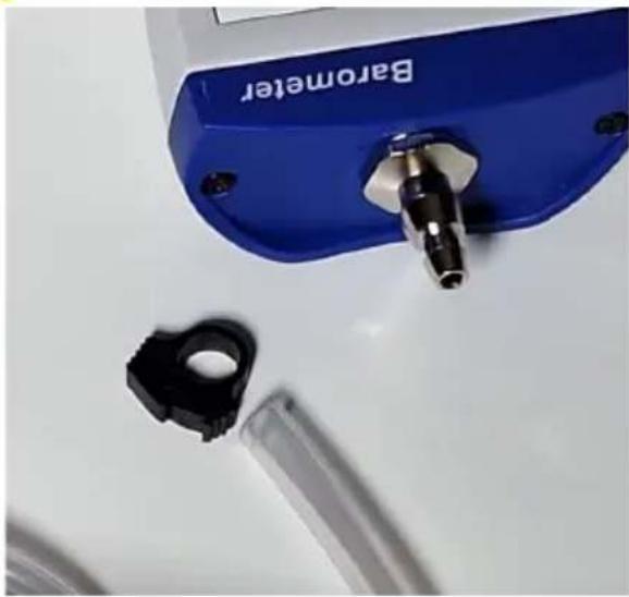
natural_image
Close-up of a blue BARometer device with a black plastic clip attached, next to a transparent cylindrical object (no text or symbols visible)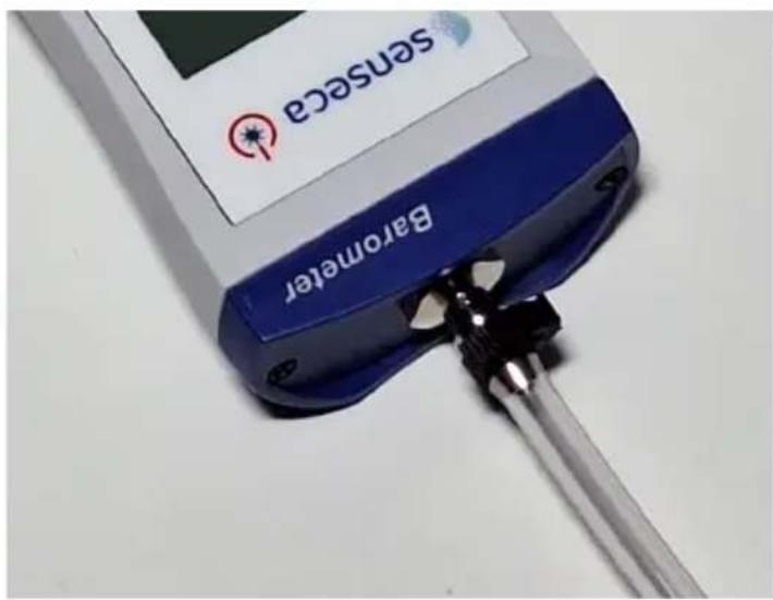
5.2.1 Replacement of pressure hoses
The pressure connections are screwed into the product with a standard G 1/8 inch thread with end seal. All common pressure connections with this design can be connected.
Note
Use a suitable tool for tightening and observe the maximum torque of 2 Nm!
Supplied connection:
| Typ Picture | Description | |
| .. - UT | 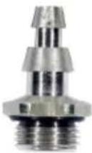 | Universal hose connection for 6 x 1 mm (4 mm inside) and 8 x 1 mm (6 mm inside) hoses. |
| The universal hose connection is suitable for plastic and silicon hoses with an outer diameter of 6 mm, for which purpose the hoses are simply connected to the upper part. Rubber/silicon hoses with a larger diameter (e.g. 8 mm) can also be connected. They are fit on the lower part for this purpose. | ||
| .. - QC6 | 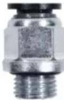 | Quick-Connect for ∅ 6 mm hoses. |
| The practical quick-change connection is only suitable for plastic hoses with 6 mm outer diameter. The hose end must be clean and undamaged for connection. It is fit by simply pushing it in until the mechanical stop is reached. It is disconnected by simultaneously pressing the ring on the upper end of the connection and pulling the hose. | ||
| .. - ST6 | 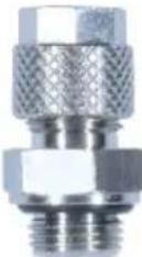 | Screw connection for 6 x 1 mm (∅ 4 mm inside) plastic hoses. |
| The secure screw connection is only suitable for plastic hoses with 6 mm outer diameter (∅ 4 mm inside). The hose end must be clean and undamaged for connection. The union nut must be loosened before connection. Then the hose is pushed onto the hose nipple up to the mechanical stop. The union nut is hand-tightened to secure the connection. Disconnection takes place by loosening the union nut and pulling on the hose. | ||
| .. - MCM | 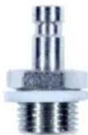 | MCM mini-quick-coupler plug connector. |
Compatible quick-couplers with nominal width 2.7 mm can be used: 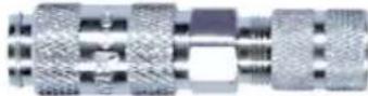 |
6 Operation and maintenance
6.1 Operating and maintenance notices
Note
Pressure connections must be protected from soiling.
6.2 Battery
6.2.1 Battery indicator
If the empty frame in the battery display blinks, the batteries are depleted and must be replaced. However, the device will still operate for a certain length of time.
If the BAT display text appears in the main display, the battery voltage is no longer adequate for operation of the device. The battery is fully depleted.

Danger Danger of explosion!
Using damaged or unsuitable batteries can generate heat, which can cause the batteries to crack and possibly explode!
▶ Only use high-quality and suitable alkaline batteries!

Caution Damage
If the batteries have different charge levels, leaks and thus damage to the device can occur.
▶ Only use high-quality and suitable alkaline batteries!
▶ Do not use different types of batteries!
▶ Remove depleted batteries immediately and dispose of them at a suitable collection point.
Note
▶ Unnecessary unscrewing endangers the protection against moisture and should therefore be avoided.
▶ Read the following handling instructions before replacing batteries and follow them step by step.
▶ If disregarded, the device could be damaged or the protection from moisture could be diminished.
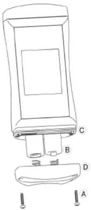
1 Unscrews the Phillips screws (A) and remove the cover.
2 Carefully replace the two Mignon AA batteries (B). Ensure that the polarity is correct! It must be possible to insert the batteries in the correct position without using force.
3 The O-ring (C) must be undamaged, clean and positioned at the intended depth.
4 Fit the cover (D) on evenly. The O-ring must remain at the intended depth!
5 Tighten the Phillips screws (A).
7 Disposal
Separation by material and recycling of device components and packaging must take place at the time of disposal. The valid regional statutory regulations and directives applicable at the time must be observed.
Note

vice must not be disposed of with household waste. Return it to us, freight prepaid. We will then arrange for the proper and environmentally friendly disposal.
Private end users in Germany have the possibility of dropping off the device at the municipal collection center. Batteries must be removed beforehand!
Please dispose of empty batteries at the collection points intended for this purpose.
8 Error and system messages
| Display | Meaning | Possible causes | Remedy |
| ---- Calculation not possible | Measurement data acquisition is running | Waiting for data collection | |
| No display, unclear characters or no response when buttons are pressed | Battery depletedSystem errorProduct is defective | Battery depletedError in the productProduct is defective | Replace batterySend in for repair |
| BAT | Battery depleted | Battery depleted | Replace battery |
| ERR.1 | Measuring range exceeded | Measurement too highProduct is defective | Stay within allowable measurement rangeSend in for repair |
| ERR.2 | Measuring range is undercut | Measurement too lowProduct is defective | Stay within allowable measurement rangeSend in for repair |
| ERR.3 | Display range has been exceeded | Incorrect display unitIncorrect resolutionF,NE Function active | Correct settingDeactivate function |
| ERR.4 | Display range has been undercut | Incorrect display unitIncorrect resolutionF,NE Function active | Correct settingDeactivate function |
| SYS ERR | System error | Error in the product | Switch product on/offReplace batteriesSend in for repair |
9 Technical data
| ECO 210-3 | Measuring range (Hi) | Measuring range (Lo) |
| Measuring range | -200.0 .. +200.0 hPa (mbar)-2.900 .. +2.900 PSI-150.0 .. +150.0 mmHg (Torr) | 2000 .. +2000 Pa-20.00 .. +20.00 hPa (mbar)-20.00 .. +20.00 mmHg (Torr) |
| Overload | Max. ± 1700 hPa | |
| ECO 210-5 | Measuring range (Hi) | Measuring range (Lo) |
| Measuring range | -2000 .. +2000 hPa (mbar)-2.000 .. +2.000 bar-29.00 .. +29.00 PSI-1500 .. +1500 mmHg (Torr) | -200.0 .. +200.0 hPa (mbar)-200.0 .. +200.0 mmHg (Torr) |
| Overload | Max. ± 3100 hPa | |
| Accuracy | Typ.:± 0.1 % FSS (at nominal temperature 25 °C)Max.: ± 1 % FSS | |
| Measuring medium | air or non-corrosive/non-ionizing gases | |
| Pressure connection | 2 hose connections, interchangeable with G1/8 universal ports | |
| Measuring cycle | FAST: approx. 25 measurements per secondSLO: approx. 2.5 measurements per second | |
| Display 3-line segment L | CD, additional symbols, illuminated (white, duration adjustable) | |
| Standard function Min/Max/Hold | ||
| Activatable special functions | NVLL: Tare functionF,NE: Measurement resolution 0.1 Pa (ECO 210-3) / 1 Pa (ECO 210-5)AVR: Averaging over 2 s / 5 s / 10 s | |
| Adjustment | Zero point and gradient adjustment | |
| Housing | Break-proof ABS housing | |
| Protection rating | IP67 (pressure connections must be protected from soiling and moisture) | |
| Dimensions | 108 * 54 * 28 mm without pressure connection | |
| Weight | 150 g, incl. batteries | |
| Nominal temperature | 25 °C | |
| Operating conditions | -20 to 50 °C; 0 to 95 %RH (temporarily 100 %RH) | |
| Storage temperature | -20 to +70 °C | |
| Current supply | 2 * AA batteries (mignon) | |
| Current requirement | approx. 1 mA, approx. 3 mA with backlight (with slow measuring range) | |
| Directives and standards | The devices conform to the following Directives of the Council for the harmonization of legal regulations of the Member States:2014/30/EU EMC Directive2011/65/EU RoHSApplied harmonized standards:EN 61326-1:2013 Emission limits: Class BImmunity according to Table 2Additional errors: < 1 % FSEN IEC 63000:2018The device is intended for mobile use and/or stationary operation in the scope of the specified operating conditions without further limitations. | |
10 Service
10.1 Manufacturer
If you have any questions, please do not hesitate to contact us.
10.2 Calibration and adjustment service
The purpose of the calibration is to verify the precision of the measuring device by comparing it with a traceable reference.
Both ISO calibration certificates and DAkkS calibration certificates are available from Senseca.
Note
The ISO standard 9001 is applied for the iso-calibration certificates.
These certificates area affordable alternative to the DAkkS calibration certificates and provide information of the traceable reference, a list of individual values and documentation.
The DAkkS calibration is based on DIN EN ISO/17025, the accreditation basis is recognized worldwide. These certificates offer high-quality calibration and consistently high quality. The DAkkS calibration includes any necessary adjustment with the purpose of minimizing a deviation of the measuring device.
▶ The device is delivered with a test report.
This confirms that the measuring device has been adjusted and tested, without making any further statement about the accuracy.
▶ Only the manufacturer can check the basic settings and make corrections if necessary.
senseca.com

Senseca Germany GmbH
- Table of contents
- About this documentation
- Foreword
- Legal notices
- Further information
- Note
- Safety
- Danger
- Caution
- Foreseeable misuse
- ⚠️ Danger Incorrect area of application!
- Safety instructions
- Intended use
- Qualified personnel
- The product at a glance
- Display elements
- Connections
- Operating elements
- On / Off button
- Up / Down button
- Function button
- Operation
- Opening the configuration menu
- Open the adjustment menu
- Formula:
- Measurement Basics
- Special functions
- NVLL Tare function
- AVR 0:02 / AVR 0:05 / AVR 0:10
- Pressure Connection
- Caution Air pressure at port variant UT!
- Replacement of pressure hoses
- Operation and maintenance
- Operating and maintenance notices
- Battery
- Battery indicator
- Danger Danger of explosion!
- Caution Damage
- Disposal
- Technical data
- Service
- Manufacturer
- Calibration and adjustment service
Brand : Senseca
Model : ECO 210-5
Category : Uncategorized