
H14DSG-OD - Computer Server Supermicro - Free user manual and instructions
Find the device manual for free H14DSG-OD Supermicro in PDF.


| Product Type | Server Motherboard |
| Brand | Supermicro |
| Model | H14DSG-OD |
| Form Factor | E-ATX (12" x 13") |
| Socket Type | Dual LGA 4677 (Intel Xeon Scalable) |
| Memory Support | DDR5, up to 4TB, 32 DIMM slots |
| Storage Interfaces | 8x SATA3, 4x M.2 NVMe, 2x U.2 |
| PCIe Slots | 7x PCIe 5.0 x16 |
| Networking | 2x 10GbE, 2x 1GbE |
| Power Connectors | 2x EPS12V, 1x 24-pin ATX |
| Remote Management | IPMI 2.0 with dedicated LAN |
| Operating Temperature | 0°C to 50°C |
| Dimensions (W x D) | 12" x 13" (305 x 330 mm) |
| Weight | Approximately 3.5 lbs (1.6 kg) |
Frequently Asked Questions - H14DSG-OD Supermicro
User questions about H14DSG-OD Supermicro
0 question about this device. Answer the ones you know or ask your own.
Ask a new question about this device
Download the instructions for your Computer Server in PDF format for free! Find your manual H14DSG-OD - Supermicro and take your electronic device back in hand. On this page are published all the documents necessary for the use of your device. H14DSG-OD by Supermicro.
USER MANUAL H14DSG-OD Supermicro
The information in this User's Manual has been carefully reviewed and is believed to be accurate. The vendor assumes no responsibility for any inaccuracies that may be contained in this document, and makes no commitment to update or to keep current the information in this manual, or to notify any person or organization of the updates. Note: For the most up-to-date version of this manual, see our website at https://www.supermicro.com.
Super Micro Computer, Inc. ("Supermicro") reserves the right to make changes to the product described in this manual at any time and without notice. This product, including software and documentation, is the property of Supermicro and/or its licensors, and is supplied only under a license. Any use or reproduction of this product is not allowed, except as expressly permitted by the terms of said license.
IN NO EVENT WILL Super Micro Computer, Inc. BE LIABLE FOR DIRECT, INDIRECT, SPECIAL, INCIDENTAL, SPECULATIVE OR CONSEQUENTIAL DAMAGES ARISING FROM THE USE OR INABILITY TO USE THIS PRODUCT OR DOCUMENTATION, EVEN IF ADVISED OF THE POSSIBILITY OF SUCH DAMAGES. IN PARTICULAR, SUPER MICRO COMPUTER, INC. SHALL NOT HAVE LIABILITY FOR ANY HARDWARE, SOFTWARE, OR DATA STORED OR USED WITH THE PRODUCT, INCLUDING THE COSTS OF REPAIRING, REPLACING, INTEGRATING, INSTALLING OR RECOVERING SUCH HARDWARE, SOFTWARE, OR DATA.
Any disputes arising between manufacturer and customer shall be governed by the laws of Santa Clara County in the State of California, USA. The State of California, County of Santa Clara shall be the exclusive venue for the resolution of any such disputes. Supermicro's total liability for all claims will not exceed the price paid for the hardware product.
FCC Statement: This equipment has been tested and found to comply with the limits for a Class A or Class B digital device pursuant to Part 15 of the FCC Rules. These limits are designed to provide reasonable protection against harmful interference when the equipment is operated in industrial environment for Class A device or in residential environment for Class B device. This equipment generates, uses, and can radiate radio frequency energy and, if not installed and used in accordance with the manufacturer's instruction manual, may cause harmful interference with radio communications. Operation of this equipment in a residential area is likely to cause harmful interference, in which case you will be required to correct the interference at your own expense.
California Best Management Practices Regulations for Perchlorate Materials: This Perchlorate warning applies only to products containing CR (Manganese Dioxide) Lithium coin cells. "Perchlorate Material-special handling may apply. See https://www.dtsc.ca.gov/hazardouswaste/perchlorate".

WARNING: This product can expose you to chemicals including lead, known to the State of California to cause cancer and birth defects or other reproductive harm. For more information, go to https://www.P65Warnings.ca.gov.

The products sold by Supermicro are not intended for and will not be used in life support systems, medical equipment, nuclear facilities or systems, aircraft, aircraft devices, aircraft/emergency communication devices or other critical systems whose failure to perform be reasonably expected to result in significant injury or loss of life or catastrophic property damage. Accordingly, Supermicro disclaims any and all liability, and should buyer use or sell such products for use in such ultra-hazardous applications, it does so entirely at its own risk. Furthermore, buyer agrees to fully indemnify, defend and hold Supermicro harmless for and against any and all claims, demands, actions, litigation, and proceedings of any kind arising out of or related to such ultra-hazardous use or sale.
Manual Revision 1.0
Release Date: January 07, 2025
Unless you request and receive written permission from Super Micro Computer, Inc., you may not copy any part of this document. Information in this document is subject to change without notice. Other products and companies referred to herein are trademarks or registered trademarks of their respective companies or mark holders.
Copyright © 2025 by Super Micro Computer, Inc.
All rights reserved.
Published in the United States of America
Preface
About This Manual
This manual is written for professional system integrators and PC technicians. It provides information for the installation and use of the H14DSG-OD motherboard. Installation and maintenance should be performed by certified service technicians only.
Notes
For your system to work properly, follow the links below to download all necessary drivers/utilities and the user's manual for your server.
• Supermicro product manuals: https://www.supermicro.com/support/manuals
• Product drivers and utilities: https://www.supermicro.com/wdl
- Product safety info: https://www.supermicro.com/about/policies/safety_information.cfm
- A secure data deletion tool designed to fully erase all data from storage devices can be found on our website: https://www.supermicro.com/about/policies/disclaimer.cfm?url=/wdl/utility/Lot9_Secure_Data_Deletion_Utility
- Frequently Asked Questions: https://www.supermicro.com/FAQ/index.php
- If you still have questions after referring to our FAQs, contact our support team. Region-specific Technical Support email addresses can be found at: "Contacting Supermicro" on page 9
- If you have any feedback on Supermicro product manuals, contact our writing team at: Techwriterteam@supermicro.com
This manual may be periodically updated without notice. Check the Supermicro website for possible updates to the manual revision level.
Conventions Used in the Manual
Special attention should be given to the following symbols for proper installation and to prevent damage done to the components or injury to yourself.

Warning! Indicates important information given to prevent equipment/property damage or personal injury.

Warning! Indicates high voltage may be encountered while performing a procedure.
Important: Important information given to ensure proper system installation or to relay safety precautions.
Note: Additional information given to differentiate various models or to provide information for proper system setup.
Contents
Contacting Supermicro 9.
Chapter 1: Introduction 10.
1.1 Quick Reference 12
Motherboard Layout 12.
Quick Reference Table 14.
System Block Diagram 16
1.2 Motherboard Features 17
1.3 Platform Overview 19
1.4 System Health Monitoring 20
Onboard Voltage Monitors 20
Fan Status Monitor with Firmware Control.20
Environmental Temperature Control 20.
1.5 ACPI Features 21
Chapter 2: Component Installation 22
2.1 Static-Sensitive Devices 24.
Precautions 24
Unpacking 24
2.2 Motherboard Installation 25.
Tools Needed 25
Location of Mounting Holes 25
Installing the Motherboard 27
2.3 Processor and Heatsink Installation
Preparing the Processor Socket 29
Installing the Processor into the Frame 31
Installing the Heatsink 33
Uninstalling the Heatsink and Processor 34
2.4 Memory Support and Installation
Memory Support 36
General Guidelines for Optimizing Memory Performance 36
DIMM Population 37
DIMM Installation 38
DIMM Removal 4.1
2.5 Battery Removal and Installation 42
Battery Removal 42.
Proper Battery Disposal 42
Battery Installation 42.
2.6 Connections, Jumpers, and LEDs 43
Power Supply Connections 43.
Power Supply 43
Power Supply Connectors 43
Fan Board 54 V 8-pin Connector.43
Backplane and BlueField-3 Card 12 V 8-pin Power Connectors 43
E1.S Backplane, M.2 Module, BlueField-3 Risers, and BlueField-3 Bridge Boards 12 V 4-pin Power Connectors 44
Headers and Connections 44.
Fan Headers (FAN1 to FAN5) 44
TPM/Port 80 Header 45
NC-SI Connection 45
Fan Board I2C Header 46
NVMe / SATA I2C Header 46
Liquid Cooling Leak Detection Connector 47
MCIO M.2 NVMe Connector 47
Midplane and NIC Card Carrier Board Connectors 47
SATA Port 47
Front/Rear I/O Module Connectors 47
I/O Module Connectors 47
Jumper Settings 48
CMOS Clear 48
JPG1 49
JUID1 49
LED Indicators 49
Onboard Power LED (LED1) 49
RoT Status LED (LED2) 50
BMC Heartbeat LED (LED3) 50
Chapter 3: Troubleshooting 51.
3.1 Troubleshooting Procedures 52.
Before Power On 52.
No Power 52.
No Video 52.
System Boot Failure 52.
Memory Errors 53.
Losing the System's Setup Configuration 53
If the System Becomes Unstable .53
3.2 Technical Support Procedures 55
3.3 Motherboard Battery 56
3.4 Where to Get Replacement Components 57
3.5 Returning Merchandise for Service 58
3.6 Feedback 59
Chapter 4: UEFI BIOS 60
4.1 Introduction 61
Updating BIOS 61
Starting the Setup Utility 61
4.2 Main Setup 63
4.3 Advanced Setup Configuration 65
Boot Feature 65
CPU Configuration 67
NB Configuration 7.1
ACPI Settings 74
Super IO Configuration Menu 75
Serial Port 1 Configuration Menu 75
Serial Port 2 Configuration Menu 76
Serial Port Console Redirection Menu 76
PCIe/PCI/PnP Configuration Menu 78
USB Configuration 80
Network Configuration Menu 81
SATA Configuration Menu 83
HTTP Boot Configuration Menu 83
Supermicro KMS Server Configuration 84
Super-Guardians Configuration 86
TLS Authenticate Configuration 88
RAM Disk Configuration 88
BROADCOM Configuration Utility 89
Driver Health Menu 90....
4.4 BMC 92
System Event Log Menu 92
BMC Network Configuration Menu 93
4.5 Event Logs 96
4.6 Security 98
4.7 Boot 101
4.8 Save & Exit 103
Appendix A: Software 105
Microsoft Windows OS Installation 105
Installing the OS 105
Driver Installation 107
BMC 109
BMC ADMIN User Password 109
Appendix B: Standardized Warning Statements 110
Battery Handling 110
Product Disposal 112
Contacting Supermicro
Headquarters
Address: Super Micro Computer, Inc.
980 Rock Ave.
San Jose, CA 95131 U.S.A.
Tel: +1 (408) 503-8000
Fax: +1 (408) 503-8008
Email: Marketing@supermicro.com (General Information)
Sales-USA@supermicro.com (Sales Inquiries)
Government Sales-USA@supermicro.com (Gov. Sales Inquiries)
Support@supermicro.com (Technical Support)
RMA@Supermicro.com (RMA Support)
Webmaster@supermicro.com (Webmaster)
Website: https://www.supermicro.com
Europe
Address: Super Micro Computer B.V.
's-Hertogenbosch, The Netherlands
Tel: +31 (0) 73-6400390
Fax: +31 (0) 73-6416525
Email: Sales_Europe@supermicro.com (Sales Inquiries)
Support Europe@supermicro.com (Technical Support)
RMA Europe@supermicro.com (RMA Support)
Website: https://www.supermicro.nl
Asia-Pacific
Address: Super Micro Computer, Inc.
3F, No. 150, Jian 1st Rd.
Zhonghe Dist., New Taipei City 235 Taiwan (R.O.C)
Tel: +886 (2) 8226-3990
Fax: +886 (2) 8226-3992
Email: Sales-Asia@supermicro.com.tw (Sales Inquiries)
Support@supermicro.com.tw (Technical Support)
RMA@supermicro.com.tw (RMA Support)
Website: https://www.supermicro.com.tw
Chapter 1:
Introduction
Congratulations on purchasing your computer motherboard from an industry leader. Supermicro motherboards are designed to provide you with the highest standards in quality and performance.
1.1 Quick Reference 12
Motherboard Layout 12.
Quick Reference Table 14.
System Block Diagram 16.
1.2 Motherboard Features 17
1.3 Platform Overview 19
1.4 System Health Monitoring 20
Onboard Voltage Monitors 20.
Fan Status Monitor with Firmware Control 20
Environmental Temperature Control 20
1.5 ACPI Features 21

natural_image
Green printed circuit board with multiple CPU modules and memory chips, no readable text or symbols present.Figure 1-1. Motherboard Image
1.1 Quick Reference
For details on the H14DSG-OD motherboard layout, features, and other quick reference information, refer to the content below.
Motherboard Layout

Figure 1-2. Motherboard Layout
Notes:
- See "Component Installation" on page 22 for detailed information on jumpers, connectors, and LED indicators.
- "■" indicates the location of pin 1.
- Components not documented are for internal testing-purposes only.
- Use only the correct type of onboard CMOS battery as specified by the manufacturer. Do not install the onboard battery upside down to avoid possible explosion.
Quick Reference Table
| Jumper Description Default Setting | ||
| JBT1 CMOS | Clear Open (Normal) | |
| JPFR1 PFR | Function Open (Normal) | |
| JPFR2 PFR | Function Open (Normal) | |
| JPFR3 PFR | Function Open (Normal) | |
| JPG1 VGA | Enable/Disable Pins 1-2 (Enable) | |
| JUID1 Switch | Function UID/Reset Pins 1-2 (UID) | |
| LED Description Status | ||
| LED1 Power LED Solid Green | Power On | |
| LED2 Rot Status LED | Off: NormalRed on: Fail | |
| LED3 BMC Heartbeat LED | Green: Blinking (BMC Normal)Green: Fast Blinking (BMC Initializing) | |
| Connector Description | |
| FAN1-FAN5 6-pin | System Cooling Fan Headers |
| JFP1 | Front Control Panel Connector |
| JLC0-3 | 2-pin 2.048 V Header for Liquid-Cooled Solution |
| JMCIO_P0G3AJMCIO_P0G3B | PCIe 5.0 x8 (Processor 1) |
| JMCIO_P1G1AJMCIO_P1G1B | PCIe 5.0 x8 (Processor 2) |
| JMCIO_P1P4 | PCIe 3.0 x4 (Processor 2) for M.2 Module(AOC-SMG4-2M2 or AOM-S3808NI-4NM) |
| JNIC1-JNIC6 | PCIe Connections to NIC Card Carrier Board (AOM-DP805-LPIO) |
| JNCSIBF3 | NCSI Connector |
| JNVME1-4 | PCIe 5.0 x8 Ports to Backplane(Vpp available through JNVME1 and JNVME3) |
| Connector | Description |
| JP3 Front Fan Board | I2C |
| JPWR3, JPWR12 | 12 V Power to BF3 Card |
| JPWR4 | 12 V Power to Backplane(BPN-NVME5-HS119N-S8L or BPN-NVME5-LB16A-S10) |
| JPWR6 54 V Power | to Front Fan Board (AOM-528G-FAN-CAS2) |
| JPWR11 12 V Power | to E1.S (BPN-E1S5-GP101M) |
| JPWR13 12 V Power | to M.2 Module (AOC-SMG4-2M2 or AOM-S3808NI-4NM) |
| JPWR14-15 | 12 V Power to BF3 Riser (RSC-G-6G5-GP805) and BF3 Bridge Board (AOM-BB-GP102-P) with Y cable |
| JS1 SATA Connector | to Backplane |
| JSW_P54V1 54 V | Power Connector |
| JSW_PWR1JSW_PWR2JSW_PWR4 | 12 V Power to Motherboard |
| JSW_1~JSW_8 | PCIe Connectors Connected to Middle Plane(BPN-GPU-GP403 or BPN-GPU-GP805) |
| JTPM1 Trusted Platform | Module (TPM) |
| JUSB1 USB Port | |
| JVGA1 VGA Port | |
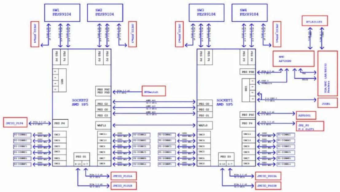
System Block Diagram
flowchart
graph TD
    subgraph Network
        A["SW1 PEZ89104"] --> B["SOCKET2 AMD SP5"]
        C["SW2 PEZ89104"] --> B
        D["SW3 PEZ89104"] --> E["SOCKET1 AMD SP5"]
        F["SW4 PEZ89104"] --> E
    end

    subgraph RSTLA211F3
        G["RTLA211F3"] --> H["JUEB1"]
        I["NPC AST2600"] --> H
        J["VIA/RPC LAM/FR222 Features"] --> H
        K["ASTIOG1"] --> L["JUE_P0 M_2 SLOT1"]
    end

    B --> M["PEO P4"]
    B --> N["WAFL1"]
    B --> O["PO 01"]
    B --> P["PO 02"]
    B --> Q["PO 03"]
    B --> R["PO 04"]
    B --> S["PO 05"]
    B --> T["PO 06"]
    B --> U["PO 07"]
    B --> V["PO 08"]
    B --> W["PO 09"]
    B --> X["PO 10"]
    B --> Y["PO 11"]
    B --> Z["PO 12"]
    B --> AA["PO 13"]

    M --> AB["INC11"]
    M --> AC["INC12"]
    M --> AD["INC13"]
    M --> AE["INC14"]
    M --> AF["INC15"]
    M --> AG["INC16"]
    M --> AH["INC17"]
    M --> AI["INC18"]
    M --> AJ["INC19"]
    M --> AK["INC20"]
    M --> AL["INC21"]
    M --> AM["INC22"]
    M --> AN["INC23"]
    M --> AO["INC24"]
    M --> AP["INC25"]
    M --> AQ["INC26"]
    M --> AR["INC27"]
    M --> AS["INC28"]
    M --> AT["INC29"]
    M --> AU["INC30"]
    M --> AV["INC31"]
    M --> AW["INC32"]
    M --> AX["INC33"]
    M --> AY["INC34"]
    M --> AZ["INC35"]
    M --> BA["INC36"]
    M --> BB["INC37"]
    M --> BC["INC38"]
    M --> BD["INC39"]
    M --> BE["INC40"]
    M --> BF["INC41"]
    M --> BG["INC42"]

    B --> BH["MFC PSC PED PSD"]
    B --> BI["NFTSwitch"]
    B --> BJ["PED PSC PED PSD"]
    B --> BK["PED Q2"]
    B --> BL["PED Q3"]
    B --> BM["PED Q4"]

    E --> BN["PED PCD"]
    E --> BO["PED PDD"]

    H --> BP["RPTLA211F3"]

    L --> BQ["NPC_P0 P0 M_2 SLOT1"]

    LQ["NPC_P0 P0 M_2 SLOT1"] --> BR["SPI-DIMMCI"]
    LQ --> BS["SPI-DIMMCI"]
    LQ --> BT["SPI-DIMMCI"]
    LQ --> BU["SPI-DIMMCI"]
    LQ --> BV["SPI-DIMMCI"]
    LQ --> BW["SPI-DIMMCI"]
    LQ --> BX["SPI-DIMMCI"]
Figure 1-3. System Block Diagram
1.2 Motherboard Features
| Motherboard Features |
| CPU |
| • Dual AMD EPYCTM 9005/9004 Series Processors in Socket SP5 |
| Memory |
| • Up to 6 TB registered ECC DDR5 4800 MT/s speed in 24 DIMM slots with AMD EPYC TM 9004 Series processors installed |
| • Up to 9 TB registered ECC DDR5 6000 MT/s speed in 24 DIMM slots with AMD EPYC TM 9005 Series processors installed |
| DIMM Size |
| • Up to 384 GB |
| Chipset |
| • System on Chip (SoC) |
| Expansion Slots |
| • Eight PCIe 5.0 x8 MCIO vertical connectors |
| • One PCIe 3.0 x4 MCIO connector for M.2 module (AOC-SMG4-2M2 or AOM-S3808NI-4NM) |
| Network |
| • AST2600 BMC chip with one gigabit RJ45 port via AOM-DP805-IO |
| Baseboard Management Controller (BMC) |
| • Aspeed AST2600 BMC |
| Graphics |
| • Aspeed AST2600 BMC chip with one VGA port via JVGA1 |
| I/O Devices |
| • One VGA port |
| • One RJ45 Dedicated LAN port |
| • One SATA 3.0 port (JS1) |
| • Two USB 3.0 ports via JUSB1 header |
| BIOS |
| • 512 Mb SPI AMI BIOS® SM Flash UEFI BIOS |
| • ACPI 6.4, SMBIOS 3.5, Plug-and-Play (PnP), RTC (Real Time Clock) wakeup, Riser Card Auto-Detection |
| Power Management |
| ACPI power management (S5)Power button override mechanismWake-On-LANPower-on mode for AC power recovery |
| System Health Monitoring |
| Onboard voltage monitoring for +3.3 V, +12 V, +3.3 VStb, +5 VStb, Vcore, VmemOnboard temperature monitoring for CPU, System, Memory, and PeripheralCPU Thermal Trip support |
| Fan Control |
| Five 6-pin fan headersFan speed control |
| System Management |
| Redundant power supply unit detection sensorSDO/SPM/SSM/SAATrusted Platform Module (TPM) support |
| LED Indicators |
| CPU / System OverheatingPower / Suspend-state IndicatorFan Failure |
| Dimensions |
| 17" (W) x 16" (L), (432 mm x 406 mm) |
1.3 Platform Overview
Built upon the functionality and capability of AMD EPYCTM in Socket SP5, the H14DSG-OD motherboard offers maximum I/O expandability, energy efficiency, and data reliability in a 3-nm (Zen 5c) and 4-nm (Zen 5) process architecture, and is optimized for embedded storage solutions, networking applications, or cloud-computing platforms.
With support of the new micro-architecture 3-nm process technology, it increases system performance for a multitude of server applications.
The following features are supported by AMD EPYC™:
• ACPI Power Management Logic Support Rev. 6.5
- Adaptive Thermal Management/Monitoring
• PCIe 5.0 with a transfer rate up to 32 GT/s
• System Management Bus (SMBus) Specification Version 3.1.1
1.4 System Health Monitoring
Onboard Voltage Monitors
An onboard voltage monitor will continuously scan the voltages of the onboard chipset, memory, processor, and battery. Once a voltage becomes unstable, a warning is given or an error message is sent to the screen. You can adjust the voltage thresholds to define the sensitivity of the voltage monitor. Real time voltage levels are displayed in IPMI.
Fan Status Monitor with Firmware Control
The system health monitor embedded in the BMC chip can check the RPM status of the cooling fans. The processor and chassis fans are controlled via IPMI.
Environmental Temperature Control
System Health sensors in the BMC monitor the temperatures and voltage settings of onboard processors and the system in real time via the IPMI interface. Whenever the temperature of the processor or the system exceeds a user-defined threshold, system/processor cooling fans will be turned on to prevent the processor or the system from overheating.
Note: To avoid possible system overheating, be sure to provide adequate airflow to your system.
1.5 ACPI Features
ACPI stands for Advanced Configuration and Power Interface. The ACPI specification defines a flexible and abstract hardware interface that provides a standard way to integrate power management features throughout a computer system, including its hardware, operating system and application software. This enables the system to automatically turn on and off peripherals such as network cards, hard disk drives, and printers.
In addition to enabling operating system-directed power management, ACPI also provides a generic system event mechanism for Plug and Play, an operating system-independent interface for configuration control. ACPI leverages the Plug and Play BIOS data structures while providing a processor architecture-independent implementation that is compatible with Windows Server 2022.
Chapter 2:
Component Installation
This chapter provides instructions on installing and replacing main system components for the H14DSG-OD motherboard. To prevent compatibility issues, only use components that match the specifications and/or part numbers given.
Installation or replacement of most components require that power first be removed from the system. Follow the procedures given in each section.
2.1 Static-Sensitive Devices 24
Precautions 24
Unpacking 24
2.2 Motherboard Installation 25
Tools Needed 25.
Location of Mounting Holes 25
Installing the Motherboard 27.
2.3 Processor and Heatsink Installation 29
Preparing the Processor Socket 29.
Installing the Processor into the Frame 31
Installing the Heatsink 33.
Uninstalling the Heatsink and Processor 34
2.4 Memory Support and Installation 36
Memory Support
General Guidelines for Optimizing Memory Performance 36
DIMM Population 37
DIMM Installation 38
DIMM Removal 41
2.5 Battery Removal and Installation 42
Battery Removal
Proper Battery Disposal 42
Battery Installation 42
2.6 Connections, Jumpers, and LEDs 43
Power Supply Connections 43
Headers and Connections 44
Front/Rear I/O Module Connectors 47
I/O Module Connectors 47
Jumper Settings 48....
LED Indicators 49
2.1 Static-Sensitive Devices
Electrostatic Discharge (ESD) can damage electronic components. To avoid damaging your motherboard, it is important to handle it very carefully. The following measures are generally sufficient to protect your equipment from ESD.
Precautions
- Use a grounded wrist strap designed to prevent static discharge.
- Touch a grounded metal object before removing the board from the antistatic bag.
- Handle the motherboard by its edges only. Do not touch its components, peripheral chips, memory modules, or gold contacts.
- When handling chips or modules, avoid touching their pins.
- Put the motherboard and peripherals back into their antistatic bags when not in use.
- For grounding purposes, make sure that your computer chassis provides excellent conductivity between the power supply, the case, the mounting fasteners, and the motherboard.
- Use only the correct type of onboard CMOS battery. Do not install the onboard battery upside down to avoid possible explosion.
Unpacking
The motherboard is shipped in antistatic packaging to avoid static damage. When unpacking the motherboard, make sure that the person handling it is static protected.
2.2 Motherboard Installation
All motherboards have standard mounting holes to fit different types of chassis. Make sure that the locations of all the mounting holes for both the motherboard and the chassis match.
Although a chassis may have both plastic and metal mounting fasteners, metal ones are highly recommended because they ground the motherboard to the chassis. Make sure that the metal standoffs click in or are screwed in tightly.
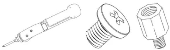
Tools Needed
natural_image
Technical line drawings of three different screw and nut components (no text or symbols)Figure 2-1. Torque Driver (1), Philips Screws (12), Standoffs (12)
Location of Mounting Holes
- To avoid damaging the motherboard and its components, do not use a force greater than 8 lbf-in on each mounting screw during motherboard installation.
- Some components are very close to the mounting holes. Take precautionary measures to avoid damaging these components when installing the motherboard to the chassis.

natural_image
Green printed circuit board with multiple CPU and memory chips, no visible text or symbols on the chip surface.Figure 2-2. Motherboard Mounting Holes
Installing the Motherboard
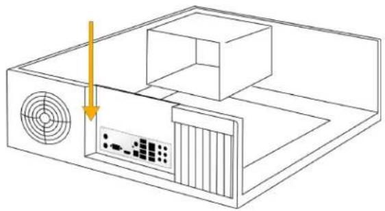
- Install the I/O shield into the back of the chassis, if applicable.
natural_image
Line drawing of a computer setup with ventilation fan and monitor (no text or symbols)Figure 2-3. Install the I/O Shield
Note: Images displayed are for illustration purposes only. The components installed in your system may or may not look exactly the same as the graphics shown in the manual.
- Locate the mounting holes on the motherboard. See Motherboard Installation for the location.

Figure 2-4. Locate the Mounting Holes
- Locate the matching mounting holes on the chassis. Align the mounting holes on the motherboard against the mounting holes on the chassis.
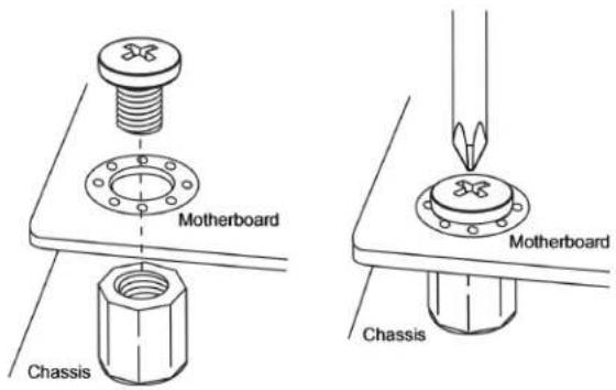
Figure 2-5. Align the Mounting Holes
- Install standoffs in the chassis as needed.
- Install the motherboard into the chassis carefully to avoid damaging other motherboard components.
- Insert pan head #6 screws into the mounting holes on the motherboard and the matching mounting holes on the chassis.
- Make sure that the motherboard is securely placed in the chassis.
2.3 Processor and Heatsink Installation
This section provides procedures to install the processor(s) and heatsink(s).
Notes:
- Take industry standard precautions to avoid ESD damage. For details, see "Static-Sensitive Devices" on page 24.
- Before starting, make sure that the plastic socket cap is in place and none of the socket pins are bent. If any damage is noted, contact your retailer.
- Do not connect the system power cord before the processor and heatsink installation is complete.
- When handling the processor, avoid touching or placing direct pressure on the LGA lands (gold contacts). Improper installation or socket misalignment can cause serious damage to the processor or processor socket.
- Install the processor in the socket and the motherboard into the chassis before installing the heatsink.
- When buying a processor separately, use only a Supermicro certified heatsink.
• Refer to the Supermicro website for the most recent processor support. - When installing the heatsink, ensure a torque driver set to the correct force is used for each screw.
- Thermal grease is pre-applied on a new heatsink. No additional thermal grease is needed.
Preparing the Processor Socket
- Remove the screw holding down the force frame. The spring-loaded force frame will raise up. Allow it to lift up to its stopped position.

natural_image
Line drawing showing two steps of assembling a CPU into a motherboard, with one hand using a tool to adjust the component (no text or symbols present)Figure 2-6. Removing Screw from the Force Frame
- Lift the rail frame up by gripping the lift tabs near the front end of the rail frame. While keeping a secure grip of the rail frame, lift it to a position so you can do the next step of removing the external cap.
Note: The rail frame is spring loaded, so keep a secure grip on it as you lift it so it does not snap up.

natural_image
Technical line drawing of an open electronic component with mounting holes and internal circuitry (no text or symbols)Figure 2-7. Lifting the Frame
- Remove the external cap from the rail frame by pulling it upwards through the rail guides on the rail frame.

natural_image
Line drawing of a hand installing or adjusting an electronic component on a baseplate, with no visible text or symbols.Figure 2-8. Remove the Cap
Installing the Processor into the Frame
-
The processor package is shipped from the factory with the carrier frame pre-assembled. Grip the handle of the carrier frame/processor assembly from its shipping tray, and while gripping the handle, align the flanges of the carrier frame onto the rails of the rail frame so its pins will be at the bottom when the rail frame is lowered later.
-
Slide the carrier frame/processor assembly downwards to the bottom of the rail frame. Ensure the flanges are secure on the rails as you lower it downwards.
Note: You can only install the processor inside the socket in one direction with the handle at the top. Make sure that it is properly inserted into the socket before closing the rail frame plate. If it doesn't close properly, do not force it as it may damage your processor. Instead, open the rail frame plate again, and double-check that the processor is aligned properly.

natural_image
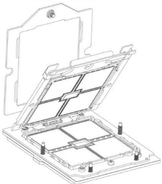
Line drawing of a hand inserting a component into a computer motherboard (no text or symbols)- Lift up the rail frame until it securely rests in upright position. Then remove the PnP cover cap from the socket below. Grip the two lift tabs marked "Remove" at the middle of the cap and pull vertically upwards to remove the PnP cover cap.
Important: The exposed socket contacts are extremely vulnerable and can be damaged easily. Do not touch or drop objects onto the contacts and be careful removing the PnP cover cap and when placing the rail frame over the socket.
natural_image
Technical line drawing of an open electrical enclosure with internal components (no text or symbols)- Gently lower the rail frame down onto the socket until the latches on the rail frame engage with the socket housing and it rests in place. Do not force it into place! Note that the force frame is spring loaded and must be held in place before it is secured.

- Use a T20 bit torque driver, set at 12.5–15.0 kgf-cm (10.8–13.0 in-lbf) to prevent damage to the processor. Replace and tighten the screws in the same order they were removed. When finished, the force frame will be secure over both the rail frame and processor package.

Installing the Heatsink
After the force frame is secured and the processor is in place, install the heatsink onto the processor.
- Place the heatsink so that it rests on the processor aligning the six screws on the socket frame.
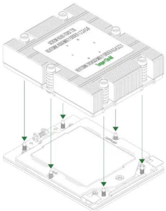
Figure 2-9. Heatsink Placement
- Using a T20 torque driver, tighten the screws using the diagonal tightening pattern and torque specifications printed on the heatsink. Tighten the two center screws completely before tightening the four corner screws.
The heatsink is now secured.
Uninstalling the Heatsink and Processor
- Remove the screws holding the heatsink and gently work it loose.
- Clean the thermal grease left by the heatsink on the processor assembly to limit the risk of it contaminating the land pads or contacts in the socket housing.
- Unscrew the plate and lift the force frame to the vertical position.
- Lift the rail frame using the lift tabs near the front end of the rail frame. Note that the rail frame is spring loaded, so be careful lifting it up into a vertical position.
- Grip the handle of the carrier frame and pull upwards to extract it from the rail frame. Return the processor assembly to its original shipping container.
-
Grip the handle on the external cap and return it to the rail frame sliding it downwards till it rests in the frame.
-
Gripping the rail frame, rotate it downwards till it rests above and locks over the socket housing in its horizontal position.
- Push and rotate down the force frame till it is over the external cap and rail frame into a horizontal position.
- While holding down the force frame, secure it back to the socket frame by securing screw #1 in place.
2.4 Memory Support and Installation
Important: Exercise extreme care when installing or removing memory modules to prevent any damage.
Note: Check the Supermicro website for recommended memory modules.
Memory Support
The H14DSG-OD supports up to 9 TB of ECC DDR5 memory in 24 DIMM slots. Refer to the tables below for additional information.
| Populating RDIMM/RDIMM 3DS DDR5 Memory Modules with AMD EPYCTM 9004 Series Processors | |||
| Type | DIMM Population Max | Maximum Frequency (MT/s) | |
| DIMM1 5600 MT/s Grade DIMM 4800 MT/s Grade DIMM | |||
| RDIMM | 1R (1 rank) | 4800 4800 | |
| 2R (2 ranks) | |||
| 3DS RDIMM | 2S2R (4 ranks) | ||
| 2S4R (8 ranks) | |||
| Populating RDIMM/RDIMM 3DS DDR5 Memory Modules with AMD EPYCTM 9005 Series Processors | ||||
| Type | DIMM Population | Maximum Frequency (MT/s) | ||
| DIMM1 | 6400 MT/sGrade DIMM | 5600 MT/sGrade DIMM | 4800 MT/sGrade DIMM | |
| RDIMM | 1R (1 rank) | 6000 5600 4800 | ||
| 2R (2 ranks) | ||||
| 3DS RDIMM | 2S2R (4 ranks) | |||
| 2S4R (8 ranks) | ||||
General Guidelines for Optimizing Memory Performance
- It is recommended to use DDR5 memory of the same type, size, and speed.
- Mixed DIMM speeds can be installed. However, all DIMMs will run at the speed of the slowest DIMM.
- The motherboard will support an odd number amount of memory modules. However, to achieve the best memory performance, a balanced memory population is recommended.
DIMM Population
This table shows the recommended slots to populate.
| DIMM Population Guide | ||||||||||||
| Slots Used | Channel | |||||||||||
| F1 E | 1 D1 | C1 B1 | A1 G | 1 H1 | 1 J1 | K1 L1 | ||||||
| One CPU | ||||||||||||
| 1 DIMM V | ||||||||||||
| 2 DIMMs V V | ||||||||||||
| 4 DIMMs V V V V | ||||||||||||
| 6 DIMMs V V V V V V | ||||||||||||
| 8 DIMMs V V V V V V V V | ||||||||||||
| 10 DIMMs V V V V V V V V V | ||||||||||||
| 12 DIMMs V V V V V V V V V V V | ||||||||||||
| Two CPUs | ||||||||||||
| 8 DIMMs | CPU1 | V V | V V | |||||||||
| CPU2 | V V | V V | ||||||||||
| 16 DIMMs | CPU1 V V V | V V V | V V V V V | |||||||||
| CPU2 V V V | V V V V V V | |||||||||||
| 24 DIMMs | CPU1 V V V V | V V V V V V V V V | ||||||||||
| CPU2 V V V V | V V V V V V V V V | |||||||||||

Figure 2-10. DIMM Labels
DIMM Installation
Important: Do not use excessive force when pressing the release tabs on the ends of the DIMM socket to avoid causing any damage to the memory module or the DIMM socket. Handle memory modules with care. Carefully follow all the instructions given in "Static-Sensitive Devices" on page 24 to avoid ESD-related damages done to your memory modules or components.
- Insert the desired number of DIMMs into the memory slots based on the recommended DIMM population table earlier in this section.
- Push the release tabs outwards on both ends of the DIMM slot to unlock it.

natural_image
Pure mechanical component diagram showing a beam with two green circular arrows indicating rotational motion (no text or symbols)Figure 2-11. Unlock the DIMM Slot
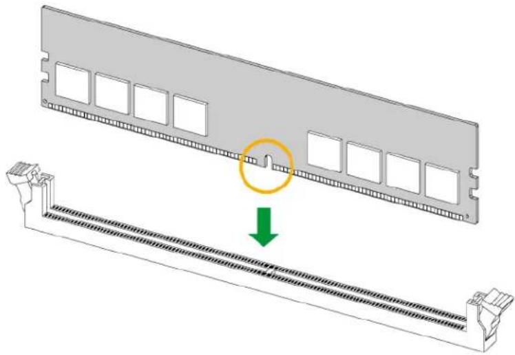
- Align the key of the DIMM with the receptive point on the memory slot.
natural_image
3D diagram of a computer RAM module with a highlighted slot and arrow indicating compression or disassembly (no text or symbols present)Figure 2-12. Align the DIMM Slot with the Receptive Point
- Align the notches on both ends of the module against the receptive points on the ends of the slot.

Figure 2-13. Align the Notches
- Press both ends of the module straight down into the slot until the module snaps into place.
- Press the release tabs to the lock positions to secure the DIMM into the slot.

Figure 2-14. Press Both Ends
For a detailed diagram of the H14DSG-OD motherboard, see the layout under "Quick Reference" on page 12.
DIMM Removal
Important: Do not use excessive force when pressing the release tabs on the ends of the DIMM socket to avoid causing any damage to the memory module or the DIMM socket. Handle memory modules with care. Carefully follow all the instructions given in "Static-Sensitive Devices" on page 24 to avoid ESD-related damages done to your memory modules or components.
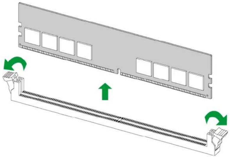
Press both release tabs on the ends of the DIMM socket to unlock it. Once the DIMM is loosened, remove it from the memory slot.
natural_image
Diagram of a computer RAM module with two green arrows indicating rotation or assembly (no text or symbols present)For a detailed diagram of the H14DSG-OD motherboard, see the layout under "Quick Reference" on page 12.
2.5 Battery Removal and Installation
Battery Removal
To remove the onboard battery, follow the steps below:
- Power off your system and unplug your power cable.
- Locate the onboard battery as shown below.
- Using a tool such as a pen or a small screwdriver, push the battery lock outwards to unlock it. Once unlocked, the battery will pop out from the holder.
- Remove the battery.
Proper Battery Disposal
Important: Handle used batteries carefully. Do not damage the battery in any way; a damaged battery may release hazardous materials into the environment. Do not discard a used battery in the garbage or a public landfill. Comply with the regulations set up by your local hazardous waste management agency to dispose of your used battery properly.
Battery Installation
To install an onboard battery, follow steps 1 and 2 above and continue below:
Important: When replacing a battery, be sure to only replace it with the same type.
- Identify the battery's polarity. The positive (+) side should be facing up.
- Insert the battery into the battery holder and push it down until you hear a click to ensure that the battery is securely locked.
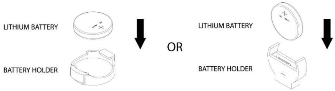
2.6 Connections, Jumpers, and LEDs
Refer to the following sections for information about connections, jumpers, and LEDs for the H14DSG-OD motherboard.
Power Supply Connections
For information about the power connections of the H14DSG-OD motherboard, refer to the following content.
Power Supply
As with all computer products, a stable power source is necessary for proper and reliable operation. It is even more important for processors that have high CPU clock rates where noisy power transmission is present.
Power Supply Connectors
The H14DSG-OD has four PowerMAX power input connectors: JSW_PWR1, JSW_PWR2, and JSW_PWR4 for 12 VDC power input via the midplane, and JSW_P54V1 for 54 VDC power input via the midplane.
Fan Board 54 V 8-pin Connector
JPWR6 is an 8-pin, 54 VDC power connector for the system's fan board. Refer to the table below for pin definitions.
| Fan Board PowerPin Definitions | |||
| Pin# Definition Pin# Definition | |||
| 1 Ground | 5 +54 V | ||
| 2 Ground | 6 +54 V | ||
| 3 Ground | 7 +54 V | ||
| 4 Ground | 8 +54 V | ||
Backplane and BlueField-3 Card 12 V 8-pin Power Connectors
JPWR3, JPWR4, and JPWR12 are 8-pin 12 VDC power inputs. JPWR3 and JPWR4 are for the system's left and right BlueField-3 cards. JPWR12 is for the system's backplane. Refer to the table below for pin definitions.
| 8-Pin PowerPin Definitions | |||
| Pin# Definition Pin# Definition | |||
| 1 Ground | 5 +12 V | ||
| 2 Ground | 6 +12 V | ||
| 3 Ground | 7 +12 V | ||
| 4 Ground | 8 +12 V | ||
E1.S Backplane, M.2 Module, BlueField-3 Risers, and BlueField-3 Bridge Boards 12 V 4-pin Power Connectors
JPWR11, JPWR13, JPWR14, and JPWR15 are 4-pin 12 VDC power inputs. JPWR11 provides power to the system's E1.S backplane. JPWR13 supplies power to the system's M.2 module. JPWR14 is used for the system's left BlueField-3 riser and BlueField-3 bridge board via a Y cable. JPWR15 powers the system's right BlueField-3 riser and BlueField-3 bridge board, also through a Y cable. Refer to the table below for pin definitions.
| 4-Pin PowerPin Definitions | |
| Pin# Definition | |
| 1 Ground | |
| 2 Ground | |
| 3 12 V | |
| 4 12 V | |
Headers and Connections
For information about the headers of the H14DSG-OD motherboard, refer to the following content.
Fan Headers (FAN1 to FAN5)
There are five fan headers (FAN1 to FAN5) on the motherboard. These are 6-pin fan headers, with pins 1-3 being backward compatible with traditional 3-pin fans. The onboard fan speeds are controlled by Fan Mode in the BMC. When using Fan Mode setting, use all 6-pin fans.
| Fan HeaderPin Definitions | |
| Pin# Definition | |
| 1 Ground (Black) | |
| 2 +12 V (Red) | |
| 3 Tachometer (Yellow) | |
| 4 PWM control (Blue) | |
| 5 12 V | |
| 6 Ground | |
TPM/Port 80 Header
The JTPM1 header on the H14DSG-OD motherboard is used to connect a Trusted Platform Module (TPM)/Port 80, which is available from Supermicro (optional). A TPM/Port 80 connector is a security device that supports encryption and authentication in hard drives. It allows the motherboard to deny access if the TPM associated with the hard drive is not installed in the system. Information on the TPM is available at the following page:
https://www.supermicro.com/manuals/other/AOM-TPM-9670V_9670H_X12_H12.pdf
For a detailed diagram of the H14DSG-OD motherboard, see the layout under "Quick Reference" on page 12.
| Trusted Platform Module HeaderPin Definitions: 10 Total | |||
| Pin# Definition Pin# Definition | |||
| 1 +3.3 V 2 | SPI_CS# | ||
| 3 RESET# 4 SPI_MISO | |||
| 5 SPI_CL | K 6 Ground | ||
| 7 SPI_MOSI 8 No Connection | |||
| 9 3V3_AUX 10 | SPI_IRQ# | ||
NC-SI Connection
The Network Controller Sideband Interface (NC-SI) connection is located at JNCSIBF3. This connection is used to connect a Network Interface Card (NIC) to the motherboard to allow the onboard Baseboard Management Controller (BMC) to communicate with a network.
Note: For detailed instructions on how to configure Network Interface Card (NIC) settings, refer to the Network Interface Card Configuration User's Guide posted on the web page under the link: https://www.supermicro.com/support/manuals.
For a detailed diagram of the H14DSG-OD motherboard, see the layout under "Quick Reference" on page 12.
Fan Board I²C Header
An I ^2 C fan header for the fan board is located at JP3. Fan speed control for this fan is supported by Thermal Management via the BMC 2.0 interface. See the table below for pin definitions.
| Fan Board I2C HeaderPin Definitions | |
| Pin# Definition | |
| 1 SDA | |
| 2 Ground | |
| 3 SCL | |
| 4 P3V3_AUX | |
NVMe / SATA I2C Header
The NVMe / SATA SMBus (I2C) header (JRSI2C1) provides hot-plug support via a dedicated SMBus interface. This feature is only available for a Supermicro complete system with an Supermicro-proprietary NVMe / SATA add-on card and a proper cable installed. See the table below for pin definitions.
| NVMe / SATA I2C HeaderPin Definitions | |
| Pin# Definition | |
| 1 SDA | |
| 2 Ground | |
| 3 SCL | |
| 4 P3V3_AUX | |
Liquid Cooling Leak Detection Connector
Four liquid cooling leak detection connectors are located at JLC0 through JLC3 on the motherboard. JLC0 is used for leak detection on the PCIe switch cold plate, JLC1 for leak detection on the CPU2 side, JLC2 for leak detection around the DIMM slots, and JLC3 for leak detection on the CPU1 side. Connect the appropriate cable from the chassis to receive notifications when a leak is detected. Refer to the table below for pin definitions.
| Leak Detection Connector (JLC0-3) Pin Definitions | |
| Pin# Definition | |
| 1 Vsen+ | |
| 2 Vsen- | |
MCIO M.2 NVMe Connector
The motherboard features a single MCIO x4 connector (JMCIO_P1P4), which is supported by CPU2. This connector supports a PCIe 3.0 x4 connection and is used for the M.2 module (AOC-SMG4-2M2 or AOM-S3808NI-4NM).
Midplane and NIC Card Carrier Board Connectors
There are eight ExaMax connectors (JSW_1 to JSW_8) on the motherboard to connect to the midplane for GPU system.
In addition, there are six PCIe 5.0 ExaMax connectors (JNIC1 to 6) to connect to the NIC card carrier board, which supports eight PCIe 5.0 x16 connections.
SATA Port
The H14DSG-OD motherboard has one SATA 3.0 port (JS1) that is supported by ASMEDIA ASM1061.
Front/Rear I/O Module Connectors
I/O Module Connectors
Two connectors on the motherboard provide I/O module connections.
- Rear I/O: BMC dedicated LAN port is supported through AOC-DP805-IO.
- Front access: The connector located at JFP1 provides connection to an I/O module. It supports one UID switch, and one UID LED indicator. Two USB 3.0 ports are supported with the JUSB1 connector. VGA is supported with the JVGA1 connector.
Jumper Settings
To modify the operation of the motherboard, jumpers can be used to choose between optional settings. Jumpers create shorts between two pins to change the function of the connector. Pin 1 is identified with a square solder pad on the printed circuit board. See the diagram below for an example of jumping pins 1 and 2. Refer to the motherboard layout page for jumper locations.
Note: On two-pin jumpers, "Closed" means the jumper is on and "Open" means the jumper is off the pins.

CMOS Clear
JBT1 on the H14DSG-OD motherboard is used to clear CMOS, which will also clear any passwords. Instead of pins, this jumper consists of contact pads to prevent accidentally clearing the contents of CMOS.
For a detailed diagram of the H14DSG-OD motherboard, see the layout under "Quick Reference" on page 12.

JBT1 contact pads
- First power down the system and unplug the power cord(s).
- Remove the cover of the chassis to access the motherboard.
- Remove the onboard battery from the motherboard.
- Short the CMOS pads, JBT1, with a metal object such as a small screwdriver for at least four seconds.
Note: Clearing CMOS will also clear all passwords.
- Remove the screwdriver (or shorting device).
- Replace the cover, reconnect the power cord(s), and power on the system.
JPG1
JPG1 enables or disables the VGA connector. The default setting is enabled.
| JPG1 | |
| Jumper Position | Definition |
| Pins 1–2 Enabled | |
| Pins 2–3 Disabled | |
JUID1
JUID1 is used for a chassis that supports a front UID button. Setting JUID1 to Pins 2-3 configures the front UID button as a reset button.
| JUID1 | |
| Jumper Position | Definition |
| Pins 1–2 Switch function UID | |
| Pins 2–3 Reset | |
LED Indicators
For information about the LED indicators on the H14DSG-OD motherboard, refer to the following content.
Onboard Power LED (LED1)
The Onboard Power LED is located at LED1 on the H14DSG-OD motherboard. When this LED is on, the system is on. Be sure to turn off the system and unplug the power cord before removing or installing components.
For a detailed diagram of the H14DSG-OD motherboard, see the layout under "Quick Reference" on page 12.
| Onboard Power LED Indicator | |
| LED Color Definition | |
| Off System Power Off (power cable not connected) | |
| Green System Power On |
RoT Status LED (LED2)
A RoT (Root-of-Trust) status LED is located at LED2 on the H14DSG-OD motherboard. When this LED is lit, it means the RoT check has failed. See the table below for more information.
| RoT Status LED Indicator | |
| LED Color Definition | |
| Green: Blinking BMC | Normal |
| Green: Blinking, fast BMC | initializing |
| Green: solid BMC Reset or Cold Boot | |
BMC Heartbeat LED (LED3)
A BMC Heartbeat LED is located at LED3 on the H14DSG-OD motherboard. When this LED is blinking, the BMC is functioning normally.
For a detailed diagram of the H14DSG-OD motherboard, see the layout under "Quick Reference" on page 12.
| BMC Heartbeat LED Indicator | |
| LED Color Definition | |
| Green: Blinking BMC Normal |
Chapter 3:
Troubleshooting
The following content contains information on common issues and how to resolve them.
3.1 Troubleshooting Procedures 52
Before Power On 52
No Power 52.
No Video 52.
System Boot Failure 52.
Memory Errors 53
Losing the System's Setup Configuration 53
If the System Becomes Unstable .53
3.2 Technical Support Procedures 55
3.3 Motherboard Battery 56
3.4 Where to Get Replacement Components 57
3.5 Returning Merchandise for Service 58
3.6 Feedback 59
3.1 Troubleshooting Procedures
Use the following procedures to troubleshoot your system. If you have followed all of the procedures below and still need assistance, refer to the "Technical Support Procedures" on page 55 or "Returning Merchandise for Service" on page 58 section(s) in this chapter. Always disconnect the AC power cord before adding, changing or installing any non hot-swap hardware components. If the below steps do not fix the setup configuration problem, contact your vendor for repairs.
Before Power On
- Make sure that there are no short circuits between the motherboard and chassis.
- Disconnect all ribbon/wire cables from the motherboard, including those for the keyboard and mouse.
- Remove all add-on cards.
- Install the processor (making sure it is fully seated) and connect the front panel connectors to the motherboard.
No Power
- Make sure that there are no short circuits between the motherboard and the chassis.
- Make sure that the power connectors are properly connected.
- Check that the 115 V/230 V switch, if available, on the power supply is properly set.
- Turn the power switch on and off to test the system, if applicable.
- Check the processor socket for bent pins and make sure the processor is fully seated.
- The battery on your motherboard may be old. Check to verify that it still supplies approximately 3 VDC. If it does not, replace it with a new one.
No Video
- If the power is on, but you do not have video, remove all add-on cards and cables.
- Remove all memory modules and turn on the system (if the alarm is on, check the specs of memory modules, reset the memory, or try a different one).
System Boot Failure
If the system does not display Power-On-Self-Test (POST) or does not respond after the power is turned on, do the following:
- Check the screen for an error message.
- Clear the CMOS settings by unplugging the power cord and contacting both pads on the CMOS clear jumper. Restart the system. Refer to "CMOS Clear" on page 48.
- Remove all components from the motherboard and turn on the system with only one DIMM installed. If the system boots, turn off the system and repopulate the components back into the system to retest. Add one component at a time to isolate which one may have caused the system boot issue.
Memory Errors
When suspecting faulty memory is causing the system issue, check the following:
- Make sure that the memory modules are compatible with the system and are properly installed. See "Component Installation" on page 22 for installation instructions. (For memory compatibility, refer to the "Tested Memory List" link on the motherboard's product page to see a list of supported memory.)
- Check if different speeds of DIMMs have been installed. It is strongly recommended that you use the same RAM type and speed for all DIMMs in the system.
- Make sure that you are using the correct type of DIMMs recommended by the manufacturer.
- Check for bad DIMMs or slots by swapping a single module among all memory slots and check the results.
Losing the System's Setup Configuration
-
Make sure that you are using a high-quality power supply. A poor-quality power supply may cause the system to lose the CMOS setup information. Refer to Introduction for details on recommended power supplies.
-
The battery on your motherboard may be old. Check to verify that it still supplies approximately 3 VDC. If it does not, replace it with a new one.
If the System Becomes Unstable
A. If the system becomes unstable during or after OS installation, check the following:
-
Processor/BIOS support: Make sure that your processor is supported and that you have the latest BIOS installed in your system.
-
Memory support: Make sure that the memory modules are supported. Refer to the product page on our website at https://www.supermicro.com. Test the modules using memtest86 or a similar utility.
Note: Click on the "Tested Memory List" link on the motherboard's product page to see a list of supported memory.
-
Storage Drive support: Make sure that all storage drives work properly. Replace the failed storage drives with good ones.
-
System cooling: Check the system cooling to make sure that all heatsink fans and processor/system fans, etc., work properly. Check the hardware monitoring settings in the IPMI to make sure that the processor and system temperatures are within the normal range. Also, check the front panel Overheat LED and make sure that it is not on.
-
Adequate power supply: Make sure that the power supply provides adequate power to the system. Make sure that all power connectors are connected. Refer to our website for more information on the minimum power requirements.
-
Proper software support: Make sure that the correct drivers are used.
B. If the system becomes unstable before or during OS installation, check the following:
-
Source of installation: Make sure that the devices used for installation are working properly, including boot devices such as a USB flash or media device.
-
Cable connection: Check to make sure that all cables are connected and working properly.
-
Use the minimum configuration for troubleshooting: Remove all unnecessary components (starting with add-on cards first), and use the minimum configuration (but with the processor and a memory module installed) to identify the trouble areas. Refer to the steps listed above in this section for proper troubleshooting procedures.
-
Identify bad components by isolating them: If necessary, remove a component in question from the chassis, and test it in isolation to make sure that it works properly. Replace a bad component with a good one.
-
Check and change one component at a time instead of changing several items at the same time. This will help isolate and identify the problem.
-
To find out if a component is good, swap this component with a new one to see if the system will work properly. If so, then the old component is bad. You can also install the component in question in another system. If the new system works, the component is good and the old system has problems.
3.2 Technical Support Procedures
Before contacting Technical Support, take the following steps. Also, note that as a motherboard manufacturer, Supermicro also sells motherboards through its channels, so it is best to first check with your distributor or reseller for troubleshooting services. They should know of any possible problems with the specific system configuration that was sold to you.
- Refer to "Troubleshooting Procedures" on page 52 or see the FAQs on our website (https://www.supermicro.com/FAQ/index.php) before contacting Technical Support.
- BIOS upgrades can be downloaded from our website (https://www.supermicro.com/support/resources/bios_ipmi.php).
-
If you still cannot resolve the problem, include the following information when contacting Supermicro for technical support:
-
Motherboard model and PCB revision number
- BIOS release date/version (This can be seen on the initial display when your system first boots up.)
-
System configuration
-
An example of a Technical Support form is on our website at https://webpr3.supermicro.com/SupportPortal.
-
Distributors: For immediate assistance, have your account number ready when placing a call to our Technical Support department. For Supermicro contact information, refer to "Contacting Supermicro" on page 9.
3.3 Motherboard Battery
For information on removing, disposing of, and replacing the motherboard battery of your system, refer to "Battery Removal and Installation" on page 42.
3.4 Where to Get Replacement Components
If you need replacement parts for your H14DSG-OD motherboard, to ensure the highest level of professional service and technical support, purchase exclusively from our Supermicro Authorized Distributors/System Integrators/Resellers. A list can be found on the Supermicro website:
https://www.supermicro.com
Under the "Buy" menu, click the "Where to Buy" link.
3.5 Returning Merchandise for Service
A receipt or copy of your invoice marked with the date of purchase is required before any warranty service will be rendered. You can obtain service by calling your vendor for a Returned Merchandise Authorization (RMA) number. When returning the motherboard to the manufacturer, the RMA number should be prominently displayed on the outside of the shipping carton, and the shipping package is mailed prepaid or hand-carried. Shipping and handling charges will be applied for all orders that must be mailed when service is complete.
For faster service, RMA authorizations can be requested online at the following page:
https://www.supermicro.com/RmaForm
Whenever possible, repack the motherboard in the original Supermicro carton, using the original packaging material. If these are no longer available, be sure to pack the motherboard securely, using packaging material to surround the motherboard so that it does not shift within the carton and become damaged during shipping.
This warranty only covers normal consumer use and does not cover damages incurred in shipping or from failure due to the alternation, misuse, abuse or improper maintenance of products.
During the warranty period, contact your distributor first for any product problems.
3.6 Feedback
Supermicro values your feedback as we strive to improve our customer experience in all facets of our business. Email us at Techwriterteam@supermicro.com to provide feedback on our manuals.
Chapter 4:
UEFI BIOS
The following content contains information on BIOS configuration with the H14DSG-OD motherboard.
4.1 Introduction 61
4.2 Main Setup 63
4.3 Advanced Setup Configuration 65
4.4 BMC 92
4.5 Event Logs 96
4.6 Security 98
4.7 Boot 101
4.8 Save & Exit 103
4.1 Introduction
This chapter describes the AMIBIOS™ Setup utility for the motherboard. The BIOS is stored on a chip and can be easily upgraded using the UEFI script (flash.nsh), the BMC WebUI, or the SuperServer Automation Assistant (SAA) utility.
Note: Due to periodic changes to the BIOS, some settings may have been added or deleted and might not yet be recorded in this manual. Refer to the Manual Download area of our website for any changes to BIOS that may not be reflected in this manual.
Updating BIOS
It is recommended that you do not upgrade your BIOS if you are not experiencing any problems with your system. Updated BIOS files are located on our website at the following page:
https://www.supermicro.com/support/resources/bios_ipmi.php
Check our BIOS warning message and the information on how to update your BIOS on our website. Select your motherboard model and download the BIOS file to your computer. Also, check the current BIOS revision to make sure that it is newer than your BIOS before downloading.
Important: Do not shut down or reset the system while updating the BIOS to prevent possible system boot failure! Read the motherboard README file carefully before you perform the BIOS update.
Unzip the BIOS file onto a bootable USB device and then boot into the built-in UEFI Shell and type "flash.nsh
Starting the Setup Utility
To enter the BIOS Setup Utility, hit the Delete key while the system is booting-up. In most cases, the
The Main BIOS screen has two main frames. The left frame displays all the options that can be configured. "Grayed-out" options cannot be configured. The right frame displays the key legend. Above the key legend is an area reserved for a text message. When an option is selected in the left frame, it is highlighted in white. Often a text message will accompany it. (Note that BIOS has default text messages built in. We retain the option to include, omit, or change any of these text messages.) Settings printed in Bold are the default values.
A "▶" indicates a submenu. Highlighting such an item and pressing the
The BIOS setup utility uses a key-based navigation system called hot keys. Most of these hot keys (
4.2 Main Setup
The Main setup screen appears when the AMI BIOS Setup utility is first entered. To return to the Main setup screen, select the Main tab at the top of the screen. The Main BIOS setup screen is shown below.
| System Date [Mon 12/09/2024] System Time [01:56:53] Supermicro H14DSG-OD BIOS Version 1.0 Build Date 10/11/2024 CPLD Version F2.65.06 Memory Information Total Memory 1572864 MB | Set the Date. Use Tab to switch between Date elements. Default Ranges: Year: 1998-9999 Months: 1-12 Days: Dependent on month Range of Years may vary. |
| ++: Select Screen ↑↓: Select Item Enter: Select +/-: Change Opt. F1: General Help F2: Previous Values F3: Optimized Defaults F4: Save & Exit ESC: Exit | |
| Version 2.22.1294 Copyright (C) 2024 AMI | |
Figure 4-1. UEFI BIOS Main Screen Tab
System Date/System Time
Use the two features to change the system date and time. Highlight System Date or System Time using the arrow keys. Enter new values using the keyboard. Press the
Note: The time is in the 24-hour format. For example, 5:30 P.M. appears as 17:30:00.
Supermicro H14DSG-OD
BIOS Version
This feature displays the version of the BIOS ROM used in the system.
Build Date
This feature displays the date when the version of the BIOS ROM used in the system was built.
CPLD Version
This feature displays the version of the Complex-Programmable Logical Device (CPLD) used in the system.
Memory Information
Total Memory
This feature displays the total size of memory available in the system.
4.3 Advanced Setup Configuration
Use the arrow keys to select the Advanced submenu and press

Figure 4-2. Advanced Setup Configuration Screen Tab
Important: Use caution when changing the Advanced settings. An incorrect value, an improper DRAM frequency, or a wrong BIOS timing setting may cause the system to malfunction. When this occurs, revert the setting to the manufacture default settings.
Boot Feature
▶ Boot Configuration
Quiet Boot
Use this feature to select the screen between displaying the Power-on Self Test (POST) messages or the OEM logo upon bootup. Select Disabled to display the POST messages. Select Enabled to display the OEM logo instead of the normal POST messages. The options
are Disabled and Enabled.
Note: BIOS POST messages are always displayed regardless of the setting of this feature.
Option ROM Messages
Use this feature to set the display mode for the Option ROM. Select Keep Current to display the current AddOn ROM display settings. Select Force BIOS to use the Option ROM display mode set by the system BIOS. The options are Force BIOS and Keep Current.
Bootup NumLock State
Use this feature to set the Power-on state
Wait For "F1" If Error
Select Enabled to force the system to wait until the
INT19 Trap Response
Interrupt 19 is the software interrupt that handles the boot disk function. When this feature is set to Immediate, the ROM BIOS of the host adaptors will "capture" Interrupt 19 at bootup immediately and allow the drives that are attached to these host adaptors to function as bootable disks. If this feature is set to Postponed, the ROM BIOS of the host adaptors will not capture Interrupt 19 immediately to allow the drives attached to these adaptors to function as bootable devices at bootup. The options are Immediate and Postponed.
Re-try Boot
If this feature is set to Enabled, the system BIOS will automatically reboot the system from an Extensible Firmware Interface (EFI) boot device after an initial boot failure. The options are Disabled, Legacy Boot, and EFI Boot.
Power Configuration
Watch Dog Function
Select Enabled to allow the Watch Dog timer to reboot the system when it is inactive for more than five minutes. The options are Disabled and Enabled.
Restore on AC Power Loss
Use this feature to set the power state after a power outage. Select Stay Off for the system power to remain off after a power loss. Select Power On for the system power to be turned on after a power loss. Select Last State to allow the system to resume its last power state before a power loss. The options are Stay off, Power On, and Last State.
Power Button Function
This feature controls how the system shuts down when the power button is pressed. Select 4 Seconds Override to power off the system after pressing and holding the power button for four seconds or longer. Select Instant Off to instantly power off the system as soon as you press the power button. The options are Instant Off and 4 Seconds Override.
CPU Configuration
CPU Configuration
Workload Profile
This function allows configuring the BIOS settings to match the selected workload. The options are Disabled, HPC, I/O, Virtualization, Telco NFVI, Telco NFVI-FP, and Telco FlexRAN.
SMT Control
This setting controls whether symmetric multithreading (SMT) is enabled. To activate SMT after disabling it, it is required to restart the computer. To use the default setting, set to Auto. The options are Disabled, Enabled, and Auto.
Core Performance Boost
This setting control whether the CPU's Core Performance Boost feature is enabled. This feature can help improve performance in certain situations. The options are Disabled and Auto.
Global C-state Control
This setting manages power-saving states (C-states) for input-output devices and deep sleep (DF) states. The options are Disabled, Enabled, and Auto.
ACPI CST C2 Latency
This setting sets the latency for C2 state transitions in microseconds, increasing this value reduces the frequency of C2 transitions and the time spent in C2 state. The default value is 100.
PPIN Opt-in
Select Unlock/Enabled to use the Protected Processor Inventory Number (PPIN) in the system. The PPIN is a unique number set for tracking a given Intel Xeon server processor. The options are Disabled, Enabled, and Auto.
SMEE
This setting controls Secure Memory Encryption (SME) for the system. The options are Disabled, Enabled, and Auto.
Fast Short REP MOVSB (FSRM)
This setting controls whether a specific memory copy instruction (REP MOVSB) is optimized for speed. The options are Auto, Enabled, and Disabled.
Enhanced REP MOVSB/STOSB (ERSM)
This setting optimizes CPU string operations. Disabling ERSM (setting it to 0) can be useful for performance analysis if supported by the operating system. The options are Disabled, Enabled, and Auto.
AVX512
This setting enables or disables AVX-512 (Advanced Vector Extensions 512), which is used for high-performance computing tasks. The options are Auto, Enabled, and Disabled.
Monitor and MWAIT Disable
This setting controls the availability of the MONITOR, MWAIT, MONITORX, and MWAITX opcodes, which are used for power management and synchronization. The options are Enabled, Disabled, and Auto.
L1 Stream HW Prefetcher
This setting is used to enable or disable the L1 Stream Hardware Prefetcher. The options are Disabled, Enabled, and Auto.
L2 Stream HW Prefetcher
This setting is used to enable or disable the L2 Stream Hardware Prefetcher. The options are Disabled, Enabled, and Auto.
CCD Control
This setting allows you to control the number of Core Complex Dies (CCDs) active in the CPU to optimize performance and power usage. The options are Auto, 2 CCDs, 4 CCDs, 6 CCDs, 8 CCDs, and 10 CCDs.
Core Control
This sets the number of cores to be used by your system. Once this option has been used to remove any cores, a power cycle is required in order for the future selections to take effect. The options are Auto, ONE (1+0), TWO (2+0), THREE (3+0), FOUR (4+0), FIVE (5+0), SIX (6+0), SEVEN (7+0), Two (1+1), FOUR (2+2), SIX (3+3), EIGHT (4+4), TEN (5+5), TWELVE (6+6), and FOURTEEN (7+7).
SVM Mode
This setting enables or disables CPU Virtualization. The options are Disabled and Enabled.
▶ CPU1 Information
CPU Configuration
These sections are for informational purposes. They will display some details about the detected CPUs on the motherboard, such as:
- CPU Version
• Number of Cores Running - Processor Family
- Processor Model
- Microcode Patch Level
• L1 Instruction Cache (Size/Method)
• L1 Data Cache (Size/Method)
• L2 Cache (Size/Method)
• L3 Cache per Socket (Size/Method)
CPU1 PCIe Package Group P2
This setting selects the PCIe port bifurcation configuration for the selected slot. The options are Auto, x4x4x4x4, x4x4x8, x8x4x4, x8x8, and x16.
CPU1 PCIe Package Group G2
This setting selects the PCIe port bifurcation configuration for the selected slot. The options are Auto, x4x4x4x4, x4x4x8, x8x4x4, x8x8, and x16.
CPU1 PCIe Package Group P3
This setting selects the PCIe port bifurcation configuration for the selected slot. The options are Auto, x4x4x4x4, x4x4x8, x8x4x4, x8x8, and x16.
CPU1 PCIe Package Group G3
This setting selects the PCIe port bifurcation configuration for the selected slot. The options are Auto, x4x4x4x4, x4x4x8, x8x4x4, x8x8, x16, and SATA.
CPU1 PCIe Package Group P1
This setting selects the PCIe port bifurcation configuration for the selected slot. The options are Auto, x4x4x4x4, x4x4x8, x8x4x4, x8x8, and x16.
CPU1 PCIe Package Group G1
This setting selects the PCIe port bifurcation configuration for the selected slot. The options are Auto, x4x4x4x4, x4x4x8, x8x4x4, x8x8, and x16.
CPU1 PCIe Package Group P0
This setting selects the PCIe port bifurcation configuration for the selected slot. The options are Auto, x4x4x4x4, x4x4x8, x8x4x4, x8x8, x16, and SATA.
CPU1 PCIe Package Group 01
This setting selects the PCIe port bifurcation configuration for the selected slot. The options are Auto, x4x4x4x4, x4x4x8, x8x4x4, x8x8, and x16.
▶ CPU2 Information
These sections are for informational purposes. They will display some details about the detected CPUs on the motherboard, such as:
- CPU Version
• Number of Cores Running - Processor Family
- Processor Model
- Microcode Patch Level
• L1 Instruction Cache (Size/Method)
• L1 Data Cache (Size/Method)
• L2 Cache (Size/Method)
• L3 Cache per Socket (Size/Method)
CPU2 PCIe Package Group P2
This setting selects the PCIe port bifurcation configuration for the selected slot. The options are Auto, x4x4x4x4, x4x4x8, x8x4x4, x8x8, and x16.
CPU2 PCIe Package Group G2
This setting selects the PCIe port bifurcation configuration for the selected slot. The options are Auto, x4x4x4x4, x4x4x8, x8x4x4, x8x8, and x16.
CPU2 PCIe Package Group P3
This setting selects the PCIe port bifurcation configuration for the selected slot. The options are Auto, x4x4x4x4, x4x4x8, x8x4x4, x8x8, and x16.
CPU2 PCIe Package Group P3
This setting selects the PCIe port bifurcation configuration for the selected slot. The options are Auto, x4x4x4x4, x4x4x8, x8x4x4, x8x8, x16, and SATA.
CPU2 PCIe Package Group P1
This setting selects the PCIe port bifurcation configuration for the selected slot. The options are Auto, x4x4x4x4, x4x4x8, x8x4x4, x8x8, and x16.
CPU2 PCIe Package Group G1
This setting selects the PCIe port bifurcation configuration for the selected slot. The options are Auto, x4x4x4x4, x4x4x8, x8x4x4, x8x8, and x16.
CPU2 PCIe Package Group P0
This setting selects the PCIe port bifurcation configuration for the selected slot. The options are Auto, x4x4x4x4, x4x4x8, x8x4x4, x8x8, x16, and SATA.
CPU2 PCIe Package Group G0
This setting selects the PCIe port bifurcation configuration for the selected slot. The options are Auto, x4x4x4x4, x4x4x8, x8x4x4, x8x8, and x16.
NB Configuration
North Bridge Configuration
IOMMU
Use this setting to enable or disable IOMMU. The options are Disabled, Enabled, and Auto.
DMAr Support
Use this setting to enable DMAr system protection during POST (Power-On Self-Test). The options are Disabled, Enabled, and Auto.
DRTM Virtual Device Support
This enables or disables the DRTM ACPI Virtual device. The options are Disabled, Enabled, and Auto.
DRTM Memory Reservation
Reserve 128 MB memory below Bottom IO for DRTM. It is required to be enabled for Secured-Core Server function. The options are Disabled, Enabled, and Auto.
ACS Enable
This setting enables Access Control Service (ACS) functionality, which requires AER to be active. The options are Enabled, Disabled, and Auto.
TDP Control
Use this setting to set the processor's power consumption (TDP). The options are Manual and Auto.
Package Power Limit Control
Use Auto to apply the default power limit (PPT) or Manual to set a custom PPT. The options are Manual and Auto.
Determinism Control
Use this setting to configure the level of performance determinism. The options are Manual and Auto.
APBDIS
Use this setting to control the APBDIS feature. A value of 0 indicates "not APBDIS" (mission mode). The options are 0, 1, and Auto.
Power Profile Selection
Use this setting to select a power profile to optimize performance or efficiency. The options are High Performance Mode, Efficiency Mode, Maximum IO Performance Mode, Balanced Memory Performance Mode, Balanced Core Performance Mode, Balanced Core Memory Performance Mode, and Auto.
DF Cstates
This setting controls the power-saving states of the data fabric. The options are Disabled, Enabled, and Auto.
Data Link Feature Cap
This setting controls the activation of advanced data link features for PCIe devices, which can improve link performance and reliability. The options are Enabled, Disabled, and Auto.
SEV-SNP Support
This setting controls the activation of Secure Encrypted Virtualization - Secure Nested Paging (SEV-SNP) security features. The options are Disabled, Enabled, and Auto.
Periodic Training Mode
This setting controls the method for managing power-saving states. The options are Disabled and Legacy.
EQ Bypass To Highest Rate
This setting determines whether the system can bypass equalization steps at lower data rates and directly attempt equalization at the highest supported rate during the link setup process. The options are Disable, Enable, and Auto.
CXL Memory Attribute
This setting determines the memory type for CXL devices. The options are Enabled, Disabled, Auto,
Sync Header Bypass
This setting controls the inclusion of synchronization headers in data transmissions. The options are Enabled, Disabled, and Auto.
▶ xGMI Configuration
xGMI Link Width Control
This setting controls the number of lanes used for the xGMI interface. When the setting is set to Manual, the "xGMI Force Link Width Control" and "xGMI Max Link Width Control" items becomes available. The options are Manual and Auto.
xGMI Link Max Speed
This setting controls the maximum speed of the xGMI link. The options are 10.667 Gbps, 11 Gbps, 12 Gbps, 13 Gbps, 14 Gbps, 15 Gbps, 16 Gbps, 17 Gbps, 18 Gbps, 19 Gbps, 20 Gbps, 21 Gbps, 22 Gbps, and Auto.
▶ Memory Configuration
Memory Target Speed
Use this setting to specify the memory target speed in MT/s. The options are Auto, DDR3600, DDR4000, DDR4400, DDR4800, DDR5200, DDR5600, DDR6000, and DDR6400.
Memory Interleaving
This setting controls fabric level memory interleaving. Note that the channel, die and socket have requirements on memory populations and it will be ignored if the memory doesn't support the selected option. The options are Disabled, Auto, and Enabled.
Chipselect Interleaving
This setting allows memory blocks to be interleaved across the DRAM chip selects for node 0, which can enhance memory performance. The options are Disabled and Auto.
BankSwapMode
This setting determines the operation of memory banks in relation to CPU usage. The options are Auto, Disabled, and Swap CPU.
Power Down Enable
Use this setting to enable or disable DDR power down mode. The options are Disabled, Enabled, and Auto.
DRAM Scrub Time
This setting specifies the frequency of memory scrubbing, which helps maintain data integrity by refreshing memory contents. The options are Disabled, 1 hour, 4 hours, 6 hours, 8 hours, 12 hours, 16 hours, 24 hours, and 48 hours.
TSME
This setting controls the Transparent Secure Memory Encryption feature. The options are Enabled, Disabled, and Auto.
Enhanced PPR
Use this setting to enable a full memory test during system setup. While this thorough testing can enhance system stability, it will also increase the overall boot time. The options are Disabled and Enabled.
▶ CPU1 Memory Information
CPU1 Memory Information
These sections are for informational purposes. They will display some details about the detected memory according to each CPU on the motherboard, such as:
• Detected Size (per slot, in MB)
• Current Speed (MT/s)
▶ CPU2 Memory Information
CPU2 Memory Information
These sections are for informational purposes. They will display some details about the detected memory according to each CPU on the motherboard, such as:
• Detected Size (per slot, in MB)
• Current Speed (MT/s)
ACPI Settings
ACPI Settings
High Precision Event Timer
The High Precision Even Timber (HPET) is a hardware timer that provides high-resolution time stamps and periodic interrupts, used by the operating system for various timing-related tasks. The options are Disabled and Enabled.
PCI AER Support
This setting controls the Advanced Error Reporting (AER) capability for PCIe devices in the system. The options are Enabled and Disabled.
NUMA Nodes Per Socket
Use this setting to specify the number of desired NUMA (Non-Uniform Memory Access) nodes per socket. Zero will attempt to interleave the two sockets together. The options are NPS0, NPS1, NPS2, NPS4, and Auto.
ACPI SRAT L3 Cache As NUMA Domain
This setting determines how the system's NUMA (Non-Uniform Memory Access) domains are defined in relation to the L3 cache. The options are Disabled, Enabled, and Auto.
Super IO Configuration Menu
▶ Super IO Configuration
Note: This submenu is available when your system supports this feature.
The following information is displayed.
- Super IO Chip
Serial Port 1 Configuration Menu
▶ Serial Port 1 Configuration
Serial Port 1
Select Enabled to enable serial port 1. The options are Disabled and Enabled.
Device Settings (Available when "Serial Port 1" above is set to Enabled)
This feature displays the base I/O port address and the Interrupt Request address of serial port 1.
Change Settings (Available when "Serial Port 1" above is set to Enabled)
Use this feature to specify the base I/O port address and the Interrupt Request address of serial port 1. Select Auto for the BIOS to automatically assign the base I/O and IRQ address to serial port 1. The options are Auto, (IO=3F8h; IRQ=4;), (IO=3F8h; IRQ=3,4,5,6,7,9,10,11,12;), (IO=2F8h; IRQ=3,4,5,6,7,9,10,11,12;), (IO=3E8h; IRQ=3,4,5,6,7,9,10,11,12;), and (IO=2E8h; IRQ=3,4,5,6,7,9,10,11,12;).
Serial Port 2 Configuration Menu
▶ Serial Port 2 Configuration
Note: It can be "Serial Port 2 Configuration" or "SOL Configuration" based on your system support.
Serial Port 2/SOL ("Serial Port 2" or "SOL" based on your system support)
Select Enabled to enable serial port 2 (or SOL). The options are Disabled and Enabled.
Device Settings (Available when "Serial Port 2/SOL" above is set to Enabled)
This feature displays the base I/O port address and the Interrupt Request address of serial port 2 (or SOL).
Change Settings (Available when "Serial Port 2/SOL" above is set to Enabled)
Use this feature to specify the base I/O port address and the Interrupt Request address of serial port 2 (or SOL). Select Auto for the BIOS to automatically assign the base I/O and IRQ address to serial port 2 (or SOL). The options are Auto, (IO=2F8h; IRQ=3;), (IO=3F8h; IRQ=3,4,5,6,7,9,10,11,12;), (IO=2F8h; IRQ=3,4,5,6,7,9,10,11,12;), (IO=3E8h; IRQ=3,4,5,6,7,9,10,11,12;), and (IO=2E8h; IRQ=3,4,5,6,7,9,10,11,12;).
Serial Port 2 Attribute (Available for Serial Port 2 only)
Select SOL to use serial port 2 as a Serial Over LAN (SOL) port for console redirection. The options are SOL and COM.
Serial Port Console Redirection Menu
COM1 (Available when your system supports the serial port of COM1)
Console Redirection
Select Enabled to enable COM port 1 for Console Redirection, which allows a client machine to be connected to a host machine at a remote site for networking. The options are Disabled and Enabled.
Note: This feature will be set to Enabled if there is no BMC support.
▶ Console Redirection Settings
Note: This submenu is available when "Console Redirection" for COM1 or SOL/COM2 is set to Enabled.
Terminal Type
Use this feature to select the target terminal emulation type for Console Redirection. Select VT100 to use the ASCII character set. Select VT100+ to add color and function key support. Select ANSI to use the extended ASCII character set. Select VT-UTF8 to use UTF8 encoding to map Unicode characters into one or more bytes. The options are VT100, VT100+, VT-UTF8, and ANSI.
Bits Per Second
Use this feature to set the transmission speed for a serial port used in Console Redirection. Make sure that the same speed is used in the host computer and the client computer. A lower transmission speed may be required for long and busy lines. The options are 9600, 19200, 38400, 57600, and 115200 (bits per second).
Data Bits
Use this feature to set the data transmission size for Console Redirection. The options are 7 and 8 (bits).
Parity
A parity bit can be sent along with regular data bits to detect data transmission errors. Select Even if the parity bit is set to 0, and the number of 1's in data bits is even. Select Odd if the parity bit is set to 0, and the number of 1's in data bits is odd. Select None if you do not want to send a parity bit with your data bits in transmission. Select Mark to add a mark as a parity bit to be sent along with the data bits. Select Space to add a Space as a parity bit to be sent with your data bits. The options are None, Even, Odd, Mark, and Space.
Stop Bits
A stop bit indicates the end of a serial data packet. Select 1 Stop Bit for standard serial data communication. Select 2 Stop Bits if slower devices are used. The options are 1 and 2.
Flow Control
Use this feature to set the flow control for Console Redirection to prevent data loss caused by buffer overflow. Send a "Stop" signal to stop sending data when the receiving buffer is full. Send a "Start" signal to start sending data when the receiving buffer is empty. The options are None and Hardware RTS/CTS.
VT-UTF8 Combo Key Support
Select Enabled to enable VT-UTF8 Combination Key support for ANSI/VT100 terminals. The options are Disabled and Enabled.
Recorder Mode
Select Enabled to capture the data displayed on a terminal and send it as text messages to a remote server. The options are Disabled and Enabled.
Resolution 100x31
Select Enabled for extended-terminal resolution support. The options are Disabled and Enabled.
Putty KeyPad
This feature selects Function Keys and KeyPad settings for Putty, which is a terminal emulator designed for the Windows OS. The options are VT100, LINUX, XTERMR6, SCO, ESCN, and VT400.
▶ Legacy Console Redirection Settings
Legacy Serial Redirection Port
Select a COM port to display redirection of legacy os and legacy oprom messages. The options are COM1 and SOL.
Resolution
On legacy os, the number of rows and columns supported redirection. The options are 80x24 and 80x25.
Redirection After BIOS Post
When bootloader is selected, then legacy console redirection is disabled before booting to legacy OS. When always is select, then legacy console redirection is enabled ofr legacy os.. The options are Always Enable and BootLoader.
Console Redirection EMS
Select Enabled to use the SOL port for Console Redirection. The options are Disabled and Enabled.
PCIe/PCI/PnP Configuration Menu
Above 4G Decoding
This setting enables 64-bit PCI device access to memory beyond 4 GB for improved memory utilization and performance. The options are Disabled and Enabled.
Re-Size BAR Support
This setting enables or disables the Re-Size Base Address Register feature for compatible PCIe devices, which allows the system to allocate more memory to the device. The options are Disabled and Enabled.
SR-IOV Support
This setting enables or disables Single Root I/O Virtualization support for the system's PCIe devices. The options are Disabled and Enabled.
BME DMA Mitigation
This setting enables or disables Bus Mastering Error (BME) Direct Memory Access (DMA) mitigation for protection during the pre-boot process. The options are Disabled and Enabled.
PCIe ARI Support
This setting enables alternative routing-ID interpretation. The options are Disabled, Enabled, and Auto.
PCIe ARI Enumeration
This setting controls the forwarding of Alternate Routing-ID Interpretation (ARI) information for each downstream port, which is essential for device identification in PCIe systems. The options are Disabled, Enabled, and Auto.
Relaxed Ordering
This setting determines whether PCI Express devices are permitted to bypass strict transaction ordering, which can lead to potential performance improvements. The options are Disabled and Enabled.
Clock Spread Spectrum
This setting allows the BIOS to monitor and reduce the level of Electromagnetic Interference (EMI) generated by system components. The options are Disabled and Enabled.
No Snoop
This setting configures the No Snoop option for PCI Express devices, determining whether memory accesses bypass the cache. The options are Disabled and Enabled.
VGA Priority
This setting allows you to choose the primary video output source for the system. The options are Onboard and External.
PCIe Ten Bit Tag Support
This setting enables the use of ten-bit tags for PCIe devices, which can improve data handling and management. The options are Disabled, Enabled, and Auto.
NVMe Firmware Source
This setting determines the source of firmware for NVMe devices, allowing you to select between native support or vendor-specific firmware. The options are Vendor Defined Firmware and AMI Native Support.
PCI Devices Option ROM Setting
CPU SLOT3-10 PCIe 5.0 x16 OPROM
This setting enables or disables the Option ROM for the SLOT3 PCIe 5.0 x16 interface. The options are Disabled and EFI.
M.2-C1 OPROM
This setting enables or disables the Option ROM for the M.2-C1 slot. The options are Disabled and EFI.
M.2-C2 OPROM
This setting enables or disables the Option ROM for the M.2-C2 slot. The options are Disabled and EFI.
Onboard Video Option ROM
This setting selects the type of firmware to be loaded for onboard video. The options are Disabled and EFI.
AOM-PTG-I2T OPROM
This setting allows you to select the firmware function to be loaded for the onboard LAN1 interface. The options are Disabled and EFI.
USB Configuration
USB Configuration
USB Module Version 29
USB Controllers: 3 XHCIs
USB Devices: 1 Keyboard, 1 Mouse, 1 Hub
XHCI Hand-off
This setting provides a workaround for operating systems that do not support XHCI hand-off. The XHCI ownership change must be claimed by the XHCI driver. The options are Enabled and Disabled.
Legacy USB Support
Select Enabled to support onboard legacy USB devices. Select Auto to disable legacy support if there are no legacy USB devices present. Select Disable to have all USB devices available for EFI applications only. The options are Enabled, Disabled, and Auto.
Network Configuration Menu
Network Stack
Select Enabled to enable Preboot Execution Environment (PXE) or Unified Extensible Firmware Interface (UEFI) for network stack support. The options are Disabled and Enabled.
IPv4 PXE Support (Available when "Network Stack" is set to Enabled)
Select Enabled to enable IPv4 PXE boot support. If this feature is disabled, it will not create the IPv4 PXE boot option. The options are Disabled and Enabled.
IPv4 HTTP Support (Available when "Network Stack" is set to Enabled)
Select Enabled to enable IPv4 HTTP boot support. If this feature is disabled, it will not create the IPv4 HTTP boot option. The options are Disabled and Enabled.
IPv6 PXE Support (Available when "Network Stack" is set to Enabled)
Select Enabled to enable IPv6 PXE boot support. If this feature is disabled, it will not create the IPv6 PXE boot option. The options are Disabled and Enabled.
IPv6 HTTP Support (Available when "Network Stack" is set to Enabled)
Select Enabled to enable IPv6 HTTP boot support. If this feature is disabled, it will not create the IPv6 HTTP boot option. The options are Disabled and Enabled.
PXE Boot Wait Time (Available when "Network Stack" is set to Enabled)
Use this feature to set the wait time (in seconds) upon which the system BIOS will wait for you to press the
Media Detect Count (Available when "Network Stack" is set to Enabled)
Use this feature to set the wait time (in seconds) for the BIOS ROM to detect the presence of a LAN media either via the Internet connection or via a LAN port. Press the <+> or <-> key on your keyboard to change the value. The default setting is 1.
▶ IPv6 Network Configuration
▶ Enter Configuration Menu
Interface Name
Interface Type
MAC address
Host addresses
Route Table
Gateway addresses
DNS addresses
Interface ID
DAD Transmit Count
The number of consecutive Neighbor Solicitation messages sent while performing Duplicate Address Detection on a tentative address. A value of zero indicates that Duplicate Address Detection is not performed. The default value is 1.
Policy
Use this feature to select how the policy is to be configured. The options are Automatic and Manual.
Save Changes and Exit
The options are Yes and No.
▶ IPv4 Network Configuration
▶ Configured (Available when set Enabled)
Enable DHCP
The options are Disabled and Enabled.
Local IP Address
Enter IP address in dotted-decimal notation. Example: 192.168.10.12
Local NetMask
Enter NetMask in dotted-deimal notation. Exmaple: 255.255.255.0
Local Gateway
Enter Gateway in dotted-decimal notation. Example: 192.168.10.1
Local DNS Servers
Enter DNS Servers in dotted-decimal notation. Example: 192.168.10.8
Save Changes and Exit
The options are Yes and No.
SATA Configuration Menu
ASMedia SATA Configuration
▶ ASMedia SATA Controller
Hot-Plug
Enable or disable hot-plug support for SATA devices, allowing them to be connected or disconnected while the system is running. The options are Disabled and Enabled.
▶ Serial ATA Controller 0 Settings
SATA Enable
The options are Disabled, Enabled, and Auto.
▶ SATA Information
HTTP Boot Configuration Menu
HTTP Boot Configuration
HTTP Boot Policy
Use this feature to set the HTTP boot policy. The options are Apply to all LANs, Apply to each LAN, and Boot Priority #1 instantly.
HTTP Boot Checks Hostname
Enable this feature for HTTPS boot to check the hostname of the TLS certificates to see if it matches the host name provided by the remote server. The options are Enabled and Disabled (WARNING: Security Risk!).
Important: Disabling "HTTPS Boot Checks Hostname" is a violation of RFC 6125 and may expose you to Man-in-the-Middle Attacks. Supermicro is not responsible for any and all security risks incurred by you disabling this feature.
Priority of HTTP Boot
Instance of Priority 1: (Available when your motherboard supports this feature)
This feature sets the rank target port. The default setting is 1.
Select IPv4 or IPv6
This feature specifies which connection the target LAN port should boot from. The options are IPv4 and IPv6.
Boot Description
Use this feature to enter a boot description, which cannot be longer than 75 characters. Please be sure to enter a boot description; otherwise, the boot option for the URI cannot be created.
Boot URI
Enter a Boot Uniform Research Identifier (URI) with 128 characters or shorter. This Boot URI determines how IPv4 Boot Option and IPv6 Boot Option will be created. This feature is only supported on Dual or EFI Boot Mode.
Supermicro KMS Server Configuration
Supermicro KMS Server IP address
Use this feature to set the Supermicro Key Management Service (KMS) server IPv4 address in dotted-decimal notation.
Second Supermicro KMS Server IP address
Use this feature to set the second Supermicro KMS server IPv4 address in dotted-decimal notation.
Supermicro KMS TCP Port number
Use this feature to set the TCP port number used in Supermicro KMS Server. The valid range is 100–9999. The default setting is 5696. Do not change the default setting unless a different TCP port number has been specified and used in the Supermicro KMS Server.
KMS Time Out
Use this feature to enter the KMS server connecting time-out (in seconds). The default setting is 5 (seconds).
TimeZone
Use this feature to set the correct time zone. The default setting is 0 (not specified).
Client UserName
Press
Client Password
Press
▶ CA Certificate
This setting provides options for managing the Certificate Authority (CA) certificate. The options are Update, Delete, and Export.
▶ Client Certificate
This setting provides options for managing the client certificate. The options are Update, Delete, and Export.
▶ Client Private Key
Use the three features to enroll factory defaults or load the KMS Transport Layer Security (TLS) certificates, which are generated by the KMS Server, from the file stored in the USB flash drive as shown below.
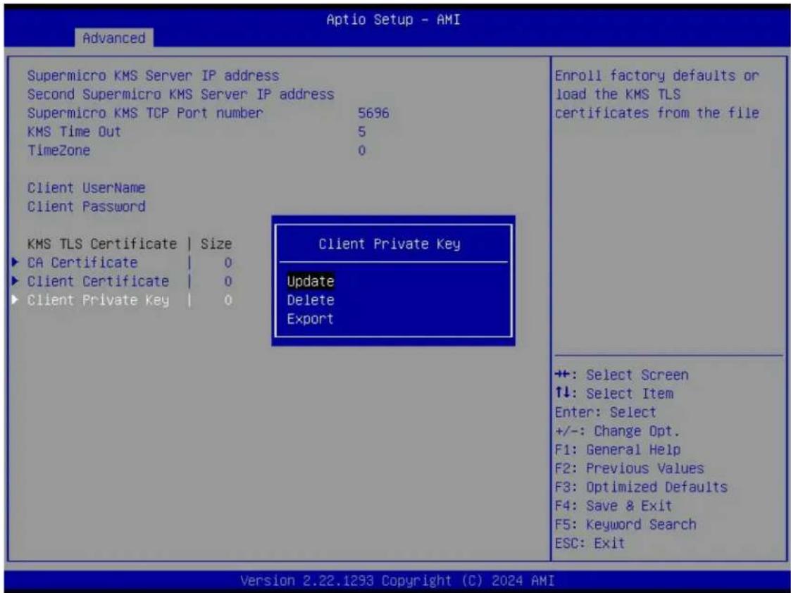
Figure 4-3. Private Key Password (Available when "Client Private Key" above has been set)
Private Key Password (Available when "Client Private Key" above has been set)
Use this feature to change the password for the client private key.
Super-Guardians Configuration
Super-Guardians Protection Policy
Use this feature to enable the Super-Guardians Protection Policy. The options are Storage, System, and System and Storage. Set this feature to Storage to protect and have secure access to Trusted Computing Group (TCG) NVMe devices with the Authentication-Key (AK). Set this feature to System to protect and have secure access to your system/motherboard with the AK. Set this feature to System and Storage to protect and have secure access to your system/motherboard/storage devices with the AK.
KMS Security Policy (Available when "TPM Security Policy" and "USB Security Policy" are set to Disabled)
Set this feature to Enabled to enable the KMS Security Policy. When this feature has not previously been set to Enabled, the options are Disabled and Enabled. Changes take effect after you save settings and reboot the system.
When this feature has previously been set to Enabled, the options are Enabled, Reset, and Key Rotation. Set this feature to Key Rotation to obtain an existing AK from the KMS server and create a new AK. To disable the KMS Security Policy, set this feature to Reset. When this feature is set to Reset, the system and TCG NVMe devices chosen in "Super-Guardians Protection Policy" will be in the unprotected mode.
Notes:
- Be sure that the KMS server is ready before configuring this feature.
- Use the professional KMS server solutions (e.g., Thales Server) or the Supermicro PyKMIP Software Package to establish the KMS server.
KMS Server Retry Count (Available when "TPM Security Policy" and "USB Security Policy" are set to Disabled)
Use this feature to specify how many times the system will attempt reconnecting to the KMS server. The valid range is 0–10. Press the <+> or <-> key on your keyboard to change the value. The default setting is 5. If the value is 0, the system will retry infinitely.
TPM Security Policy (Available when "KMS Security Policy" and "USB Security Policy" are set to Disabled)
Set this feature to Enabled to enable the TPM Security Policy. When this feature has not previously been set to Enabled, the options are Disabled and Enabled. Changes take effect after you save settings and reboot the system.
When this feature has previously been set to Enabled, the options are Enabled and Reset. To disable the TPM Security Policy, set this feature to Reset. When this feature is set to reset, the system and TCG NVMe devices chosen in "Super-Guardians Protection Policy" will be in the unprotected mode.
Note: Be sure to install a TPM 2.0 device to your system before configuring this feature.
Load Authentication-Key (Available when "KMS Security Policy," "TPM Security Policy," and "USB Security Policy" are set to Disabled)
The options are Disabled and Enabled. Set this feature to Enabled. Changes take effect after you save settings and reboot the system. While booting, the BIOS will automatically load the Authentication-Key (filename: TPMAuth.bin) from the USB flash drive. Afterwards, the default setting will be set to Disabled by the BIOS.
Notes:
- Be sure to connect a USB flash drive with the Authentication-Key (filename: TPMAuth.bin) to your system before the system reboot.
- Be sure to save the Authentication-Key (filename: TPMAuth.bin) to the USB flash drive and have a backup. Please load the Authentication-Key (filename: TPMAuth.bin) after installing a TPM device. Otherwise, the TPM function can not work properly.
Save Authentication-Key (Available when "TPM Security Policy" is set to Enabled)
The options are Disabled and Enabled. Set this feature to Enabled. Changes take effect after you save settings and reboot the system. While booting, the BIOS will automatically save the Authentication-Key (filename: TPMAuth.bin) to the USB flash drive. Afterwards, the default setting will be set to Disabled by the BIOS.
Note: Be sure to connect a USB flash drive to your system before the system reboot.
USB Security Policy (Available when "KMS Security Policy" and "TPM Security Policy" are set to Disabled)
Use this feature to enable the USB Security Policy. The options are Disabled and Enabled. Set this feature to Enabled. Changes take effect after you save settings and reboot the system. Connect a USB flash drive to your system before the system reboot. While booting, the BIOS will automatically create the USB Authentication-Key (filename: USBAuth.bin) and save it to the USB flash drive.
When this feature has been previously set to Enabled, the options are Enabled and Reset. To disable the USB Security Policy, set this feature to Reset. When this feature is set to Reset, the system and TCG NVMe devices chosen in "Super-Guardians Protection Policy" will be in the unprotected mode.
Note: Be sure to connect a USB flash drive to your system before configuring this feature. Save the USB Authentication-Key (filename: USBAuth.bin) to the USB flash drive and keep a backup.
TLS Authenticate Configuration
▶ Server CA Configuration
This feature allows you to configure the client certificate that is to be used by the server.
▶Enroll Certification
This feature allows you to enroll the certificate in the system.
▶Enroll Certification Using File
This feature allows you to enroll the security certificate in the system by using a file.
Certification GUID
Press
▶ Commit Changes and Exit
Use this feature to save all changes and exit TLS settings.
▶ Discard Changes and Exit
Use this feature to discard all changes and exit TLS settings.
▶ Delete Certification
This feature is used to delete the certificate if a certificate has been enrolled in the system.
▶ Client Certification Configuration
RAM Disk Configuration
Disk Memory Type
This setting specifies the type of memory to use from the available memory pool in the system to create a disk. the options are Boot Service Data and Reserved.
Create raw
Size (Hex):
Set the size of the RAM disk. The valid size should be multiples of the RAM disk block size.
Create & Exit or Discard & Exit.
Create from file
Created RAM disk list:
This displays a list of the created RAM disks.
Created RAM disk list:
Remove selected RAM disk(s)
BROADCOM Configuration Utility
▶ Main Menu
The menu options are as below:
▶ Configuration Management
Clear Configuration: No
▶ Controller Management
Basic Properties: Product Name/Controller Status/Personality Mode/Select Boot Device/PCI ID/PCI Segment/PCI Slot Number/Package Version/Firmware Version/NVDATA Version/Supported Device Interfaces/Drive Count/JBOD Count/Virtual Drive Count
Advanced Controller Management
Advanced Controller Properties
▶Virtual Drive Management
▶ Drive Management
▶ Hardware Components
▶ Help
The setting shows context sensitive help message.
Properties:
Status / Backplane / CacheVault / Enclosure / JBODs / Drive Groups / Virtual Drives
▶View Server Profile
The setting shows the UEFI spec version that this system supports and menu options as below:
Server:
UEFI Spec Version
▶ Controller Management
▶ Hardware Components
▶ Drive Management
▶Virtual Drive Management
Actions:
▶ Configure
The setting displays configuration options. Some options appear only if the controller supports them.
▶ Set Factory Defaults
The setting restores factory default values for all the controller properties.
▶ Update Firmware
The setting allows users to update the controller firmware to a newer version.
▶ Manage MegaRAID Advanced Software Options
The setting displays the activated Advanced Software Options on the controller and allows the user to configure the MegaRAID Advanced Software Options to use the advanced features.
Driver Health Menu
▶ Driver Health
This feature displays the health information of the drivers installed in your system, including LAN controllers, as detected by the BIOS. Select one and press
Note: This section is provided for reference only, for the driver health status will differ depending on the drivers installed in your system. It's also based on your system configuration and the environment that your system is operating in.
4.4 BMC
Use this menu to configure Baseboard Management Console (BMC) settings.
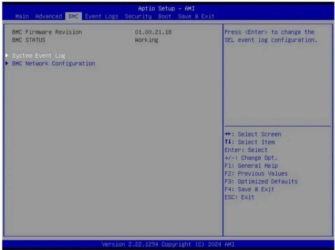
Figure 4-4. BMC Screen Tab
BMC Firmware Revision
This feature indicates the BMC firmware revision used in your system.
BMC STATUS
This feature indicates the status of the BMC firmware installed in your system.
System Event Log Menu
▶ System Event Log
Note: All values changed in this submenu do not take effect until computer is restarted.
SEL Components
Select Enabled to enable all system event logging upon system boot. The options are Disabled and Enabled.
Erasing Settings
Erase SEL (Available when "SEL Components" is set to Enabled)
Select (Yes, On next reset) to erase all system event logs upon next system boot. Select (Yes, On every reset) to erase all system event logs upon each system reboot. Select No to keep all system event logs after each system reboot. The options are No, (Yes, On next reset), and (Yes, On every reset).
When SEL is Full (Available when "SEL Components" is set to Enabled)
This feature defines what the BIOS should do when the system event log is full. Select Erase Immediately to erase all events in the log when the system event log is full. The options are Do Nothing and Erase Immediately.
BMC Network Configuration Menu
▶ BMC Network Configuration
Update BMC LAN Configuration
Select Yes for the BIOS to implement all IP/MAC address changes upon next system boot. The options are No and Yes.
Configure IPv4 Support
******************************************************************************************
BMC LAN Selection
This feature displays the type of the BMC LAN.
BMC Network Link Status:
This feature displays the status of the BMC network link for this system.
Configuration Address Source (Available when "Update BMC LAN Configuration" is set to Yes)
Use this feature to select the source of the IPv4 connection. If Static is selected, note the IP address of the IPv4 connection and enter it to the system manually in the field. If DHCP is selected, the BIOS will search for a Dynamic Host Configuration Protocol (DHCP) server in the network that is attached to and request the next available IP address for this computer. The options are Static and DHCP.
Station IP Address
This feature displays the Station IP address in decimal and in dotted quad form (i.e., 172.29.176.131). It is available for configuration when "Configuration Address Source" above is set to Static.
Subnet Mask
This feature displays the sub-network that this computer belongs to. It is available for configuration when "Configuration Address Source" above is set to Static.
Station MAC Address
This feature displays the Station MAC address for this computer. Mac addresses are six two-digit hexadecimal numbers.
Gateway IP Address
This feature displays the Gateway IP address for this computer. This should be in decimal and in dotted quad form (i.e., 172.29.0.1). It is available for configuration when "Configuration Address Source" above is set to Static.
**************************
Configure IPv6 Support
****************************************************************************************
IPv6 Address Status
This feature displays the status of the IPv6 address.
IPv6 Support (Available when "Update BMC LAN Configuration" is set to Yes)
Use this feature to enable IPv6 support. The options are Enabled and Disabled.
Configuration Address Source (Available when "IPv6 Support" is set to Enabled)
Use this feature to select the source of the IPv6 connection. If Static Configuration is selected, note the IP address of IPv6 connection and enter it to the system manually in the field. If the other two options are selected, the BIOS will search for a DHCP server in the network that is attached to and request the next available IP address for this computer. The options are Static Configuration, DHCPv6 Stateless, and DHCPv6 Stateful.
IPv6 Address ("Static," "DHCPv6 Stateless," or "DHCPv6 Stateful," depending on the option you selected for "Configuration Address Source" above)
This feature displays the station IPv6 address. It is available for configuration when "Configuration Address Source" above is set to Static Configuration.
Prefix Length
This feature displays the prefix length. It is available for configuration when "Configuration Address Source" above is set to Static Configuration.
Gateway IP
This feature displays the IPv6 gateway IP address. It is available for configuration when "Configuration Address Source" above is set to Static Configuration.
Advanced Settings (Available when "Configuration Address Source" is set to DHCPv6 Stateless)
Use this feature to set the DNS server IP. The default setting allows this system to obtain the DNS server IP automatically. The options are Auto obtain DNS server IP and Manually obtain DNS server IP.
Preferred DNS server IP (Available when "Advanced Settings" above is set to Manually obtain DNS server IP)
This feature displays the preferred DNS server IP. It can be configured via Redfish.
Alternative DNS server IP (Available when "Advanced Settings" above is set to Manually obtain DNS server IP)
This feature displays the alternative DNS server IP. It can be configured via Redfish.
****************************************************************************************
Configure VLAN Support
****************************************************************************************
Lan channel 1
VLAN Support (Available when "Update BMC LAN Configuration" is set to Yes)
Use this feature to enable the virtual LAN (VLAN) support. The options are Enabled and Disabled.
4.5 Event Logs
Use this menu to configure Event Logs settings.

Figure 4-5. Event Logs Screen Tab
Note: After you've made any changes in this section, please be sure to reboot the system for the changes to take effect.
▶ Change SMBIOS Event Log Settings
Note: Reboot the system for the changes in this section to take effect.
Enabling/Disabling Options
SMBIOS Event Log
Select Enabled to enable System Management BIOS (SMBIOS) Event Logging during system boot. The options are Disabled and Enabled.
Erasing Settings
Erase Event Log (Available when "SMBIOS Event Log" is set to Enabled)
Select No to keep the event log without erasing it upon next system bootup. Select (Yes, Next reset) to erase the event log upon next system reboot. The options are No, (Yes, Next reset), and (Yes, Every reset).
When Log is Full (Available when "SMBIOS Event Log" is set to Enabled)
Select Erase Immediately to immediately erase all errors in the SMBIOS event log when the event log is full. Select Do Nothing for the system to do nothing when the SMBIOS event log is full. The options are Do Nothing and Erase Immediately.
SMBIOS Event Log Standard Settings
Log System Boot Event (Available when "SMBIOS Event Log" is set to Enabled)
Select Enabled to log system boot events. The options are Enabled and Disabled.
MECI (Available when "SMBIOS Event Log" is set to Enabled)
Enter the increment value for the multiple event counter. Enter a number between 1 and 255. The default setting is 1. (MECI is the abbreviation for Multiple Event Count Increment.)
METW (Available when "SMBIOS Event Log" is set to Enabled)
Use this feature to determine how long (in minutes) should the multiple event counter wait before generating a new event log. Enter a number between 0 and 99. The default value is 60. (METW is the abbreviation for Multiple Event Count Time Window.)
▶ View SMBIOS Event Log
Use this feature to view the event in the system event log. Select this feature and press
4.6 Security
This menu allows you to configure the following security settings for the system.
![Aptio Setup - AMI Main Advanced BMC Event Logs Security Boot Save & Exit Administrator Password Not Installed User Password Not Installed Password Description If the Administrator's / User's password is set, then this only limits access to Setup and is asked for when entering Setup. Please set Administrator's password first in order to set User's password, if clear Administrator's password, the User's password will be cleared as well. The password length must be in the following range: Minimum length 8 Maximum length 20 Administrator Password Password Check [Setup] Supermicro Security Erase Configuration Disable Sanitize Freeze Lock [Disabled] Set Administrator Password ++: Select Screen ↑↓: Select Item Enter: Select +/-: Change Opt. F1: General Help F2: Previous Values F3: Optimized Defaults F4: Save & Exit ESC: Exit Version 2.22.1294 Copyright (C) 2024 AMI](/content/2026/05/1015879/images/0773c969fdc75209b701b40012a1cfdf0c1e6db588302a45e24a9d288fbbd53e.jpg)
Figure 4-6. Security Screen Tab
Disable Block Sid and Freeze Lock (Available when your storage devices support TCG)
Select Enabled to allow SID authentication to be performed in TCG storage devices. The options are Disabled and Enabled.
The following information is displayed:
- Administrator Password
- User Password
- Password Description
Administrator Password
This feature indicates if an administrator password has been installed. Use this feature to set the administrator password, which is required to enter the BIOS Setup utility. The length of the password can be between three and 20 characters long.
User Password (Available when "Administrator Password" has been set)
This feature indicates if a user password has been installed. Use this feature to set the user password which is required to enter the BIOS Setup utility. The length of the password can be between three and 20 characters long.
Password Check
Select Setup for the system to check for a password at Setup. Select Always for the system to check for a password at bootup and upon entering the BIOS Setup utility. The options are Setup and Always.
Hard Drive Security Frozen
Select Enabled to freeze the Lock Security feature for HDD to protect key data in hard drives from being altered. The options are Disabled and Enabled.
▶ Supermicro Security Erase Configuration
Use this submenu to configure the Supermicro-proprietary Security Erase settings. When this submenu is selected, the following information is displayed. Please note that the order of the following information may differ based on the storage devices being detected.
- HDD Name: This feature displays the name of the storage device that is detected by the BIOS.
- HDD Serial Number: This feature displays the serial number of the storage device that is detected by the BIOS.
- Security Mode: This feature displays the security mode of the storage device that is detected by the BIOS.
- Estimated Time: This feature displays the estimate time needed to perform the selected Security Erase features.
- HDD User Pwd Status: This feature indicates if a password has been set as a storage device user password which enables configuring Supermicro Security Erase settings on the storage device by using this user password.
Security Function
Select Set Password to set a storage device password which enables configuring the security settings of the storage device. Select Security Erase - Password to enter a storage device user password to enable erasing the password and the contents previously stored in the storage device. Select Security Erase - Without Password to use the manufacturer default password "111111111" as the storage device user password and enable erasing the contents of the storage device by using this default password. The options are Disabled, Set Password, Security Erase - Password, and Security Erase - Without Password.
Password
Disable Sanitize Freeze Lock
If this option is enabled, then sending Sanitize Freeze Lock command to HDDs will be skipped in next boot. The options are Disabled and Enabled.
Lockdown Mode (Available when the DCMS key is activated)
Select Enabled to support the Lockdown Mode, which prevents the existing data or keys stored in the system from being altered or changed in an effort to preserve system integrity and security. The options are Disabled and Enabled.
HDD Security Configuration:
▶ Secure Boot
The following information is displayed:
- System Mode
- Secure Boot
Note: For detailed instructions on configuring Security Boot settings, refer to the Security Boot Configuration User's Guide at https://www.supermicro.com/support/manuals.
4.7 Boot
Use this menu to configure Boot settings.
![Boot Configuration Boot Mode Select [UEFI] LEGACY to EFI Support [Disabled] FIXED BOOT Option Priorities Boot Option #1 [UEFI Hard Disk:RedHat Boot Manager (P1: INTEL SSDSC2BB080G6)] Boot Option #2 [UEFI CD/DVD] Boot Option #3 [UEFI USB Hard Disk] Boot Option #4 [UEFI USB CD/DVD] Boot Option #5 [UEFI USB Key] Boot Option #6 [UEFI USB Floppy] Boot Option #7 [UEFI USB Lan] Boot Option #8 [UEFI Network:(B81/D0/F0) UEFI PXE IPv4 Intel(R) Ethernet Controller X710 for 10GBASE-T(MAC:905A080C4 590)] Boot Option #9 [UEFI AP:UEFI: Built-in EFI Shell] Select boot mode Legacy/UEFI ++: Select Screen ↑↓: Select Item Enter: Select +/-: Change Opt. F1: General Help F2: Previous Values F3: Optimized Defaults F4: Save & Exit ESC: Exit Version 2.22.1294 Copyright (C) 2024 AMI](/content/2026/05/1015879/images/e8523a25ade7888c6388b5df24c3ead9147f18683e4ae946a71dbcd294dd5e5b.jpg)
Figure 4-7. Boot Screen Tab
Boot Configuration
Boot Mode Select
Use this feature to select boot mode. The options are Legacy, UEFI, and Dual.
Legacy to EFI Support
Use this feature to enable system to boot to EFI OS after boot failed from legacy boot order. The options are Disabled and Enabled.
FIXED BOOT ORDER Priorities
Use this feature to prioritize the order of a bootable device from which the system will boot. Press
- Boot Option #1 – Boot Option #9
▶ Add New Boot Option
Use this feature to add a new boot option to the boot priority features for system boot.
Note: This submenu is available when any storage device is detected by the BIOS.
Add boot option
Use this feature to specify the name for the new boot option.
Path for boot option
Use this feature to enter the path for the new boot option in the format fsx:\path\filename.efi.
Boot option File Path
Use this feature to specify the file path for the new boot option.
Create
After setting the name and the file path for the boot option, press
▶ Delete Boot Option
Use this feature to select a boot device to delete from the boot priority list.
Delete Boot Option
Use this feature to remove an EFI boot option from the boot priority list.
▶UEFI Hard Disk Drive BBS Priorities
Use this feature to set the system boot order of detected devices.
▶UEFI NETWORK Drive BBS Priorities
Use this feature to set the system boot order of detected devices.
▶ UEFI Application Boot Priorities
Use this feature to set the system boot order of detected devices.
4.8 Save & Exit
Select Save & Exit from the BIOS Setup screen to configure the settings below.
| Main Advanced BMC Event Logs Security Boot Save & Exit | |
| Save Options Discard Changes and Exit Save Changes and Reset Save Changes Discard Changes Default Options Restore Optimized Defaults Save as User Defaults Restore User Defaults Boot Override RedHat Boot Manager (P1: INTEL SSDSC2BB080G6) (B81/D0/F0) UEFI PXE IPv4 Intel(R) Ethernet Controller X710 for 10GBASE-T(MAC:905A080C4590) (B81/D0/F1) UEFI PXE IPv4 Intel(R) Ethernet Controller X710 for 10GBASE-T(MAC:905A080C4591) (B81/D0/F0) UEFI PXE IPv6 Intel(R) Ethernet Controller X710 for 10GBASE-T(MAC:905A080C4590) (B81/D0/F1) UEFI PXE IPv6 Intel(R) Ethernet Controller X710 for 10GBASE-T(MAC:905A080C4591) UEFI: Built-in EFI Shell Launch EFI Shell from filesystem device | Exit system setup without saving any changes. ++: Select Screen ↑↓: Select Item Enter: Select +/-: Change Opt. F1: General Help F2: Previous Values F3: Optimized Defaults F4: Save & Exit ESC: Exit |
| Version 2.22.1294 Copyright (C) 2024 AMI | |
Figure 4-8. Save & Exit Screen Tab
Save Options
Discard Changes and Exit
Use this feature to exit from the BIOS Setup utility without making any permanent changes to the system configuration and reboot the computer.
Save Changes and Reset
On completing the system configuration changes, use this feature to exit the BIOS Setup utility and reboot the computer for the new system configuration parameters to take effect.
Save Changes
On completing the system configuration changes, use this feature to save all changes made. This will not reset (reboot) the system.
Discard Changes
Select this feature and press
Default Options
Restore Optimized Defaults
Select this feature and press
Note: After pressing
Save As User Defaults
Select this feature and press
Select this feature and press
Boot Override
Note: Use this section to override the Boot priorities sequence in the Boot menu, and immediately boot the system with a device specified here instead of the one specified in the boot list. This is a one-time boot override.
Appendix A:
Software
After the H14DSG-OD motherboard has been installed, you can install the Operating System (OS), configure RAID settings, and install the drivers.
Microsoft Windows OS Installation
If you will be using RAID, you must configure RAID settings before installing the Windows OS and the RAID driver. Refer to the RAID Configuration User Guides posted on our website at https://www.supermicro.com/support/manuals.
Installing the OS
- Create a method to access the Microsoft Windows installation ISO file. That can be a USB flash or media drive, or the BMC KVM console.
- Retrieve the proper drivers. Go to the Supermicro web page for your motherboard and click on "Download the Latest Drivers and Utilities," select the proper driver, and copy it to a USB flash drive.
- Boot from a bootable device with Windows OS installation. You can see a bootable device list by pressing
during the system bootup.

Figure A-1. Select Boot Device
- During Windows Setup, continue to the dialog box where you select the drives on which to install Windows. If the disk you want to use is not listed, click on the "Load driver" link at the bottom left corner.

Figure A-2. Load Driver Link
To load the driver, browse the USB flash drive for the proper driver files.
- Once all devices are specified, continue with the installation.
- After the Windows OS installation has completed, the system will automatically reboot multiple times for system updates.
Driver Installation
The Supermicro website contains drivers and utilities for your system at the following page:
https://www.supermicro.com/wdl.
Some of these drivers and utilities must be installed, such as the chipset driver. After accessing the website, go into the CDR_Images (in the parent directory of the above link) and locate the ISO file for your motherboard. Download this file to a USB flash or media drive. You may also use a utility to extract the ISO file if preferred.
Another option is to go to the Supermicro website at https://www.supermicro.com. Find the product page for your motherboard and download the latest drivers and utilities.
Insert the flash drive or disk, and the screenshot shown below should appear.
![SUPERMICRO H14DSG-OD Motherboard Drivers & Tools (Win11) S SUPERMICRO System on Chip H14DSG-OD AMD EPYC SP5 Driver AMD EPYC SP5 PSHED Plug-in Driver Microsoft .Net Framework 4.8 [Optional] ASPEED Graphics Driver Intel PRO Network Connections Drivers Build driver diskettes and manuals Browse CD Auto Start Up Next Time For more information, please visit SUPERMICRO's web site.](/content/2026/05/1015879/images/391b9e9b632022e851976e620150d8b61b0f976a729b809575608a466a4c30a2.jpg)
Figure A-3. Driver Download Screenshot
Note: Click the icons showing a hand writing on paper to view the readme files for each item. Click the computer icons to the right of these items to install each item (from top to bottom) one at a time. After installing each item, you must reboot the system before moving on to the next item on the list. The bottom icon with a CD on it allows you to view the entire contents.
BMC
The H14DSG-OD motherboard provides remote access, monitoring, and management through the baseboard management controller (BMC) and other management controllers distributed among different system modules. There are several BIOS settings that are related to BMC. For general documentation and information on BMC, visit our website at the following page:
https://www.supermicro.com/en/solutions/management-software/bmc-resources
BMC ADMIN User Password
For security, each system is assigned a unique default BMC password for the ADMIN user. The password can be found on a sticker on the motherboard and a sticker on the chassis, for Supermicro chassis. The sticker also displays the BMC MAC address. If necessary, the password can be reset using the Supermicro IPMICFG tool.

Figure A-4. BMC Password Label
Appendix B:
Standardized Warning Statements
The following statements are industry standard warnings, provided to warn the user of situations which have the potential for bodily injury. Should you have questions or experience difficulty, contact Supermicro's Technical Support department for assistance. Only certified technicians should attempt to install or configure components.
Read this section in its entirety before installing or configuring components in the Supermicro H14DSG-OD motherboard.
These warnings may also be found on our website at https://www.supermicro.com/about/policies/safety_information.cfm.
Battery Handling

CAUTION There is risk of explosion if the battery is replaced by an incorrect type. Replace the battery only with the same or equivalent type recommended by the manufacturer. Dispose of used batteries according to the manufacturer's instructions.
電池の取り扱い
Warning! Ultimate disposal of this product should be handled according to all national laws and regulations.
製品の廃棄


- Preface
- About This Manual
- Notes
- Conventions Used in the Manual
- Contents
- Contacting Supermicro 9.
- Chapter 1: Introduction 10.
- Quick Reference 12
- Motherboard Features 17
- Platform Overview 19
- System Health Monitoring 20
- ACPI Features 21
- Chapter 2: Component Installation 22
- Static-Sensitive Devices 24.
- Motherboard Installation 25.
- Processor and Heatsink Installation
- Memory Support and Installation
- Battery Removal and Installation 42
- Connections, Jumpers, and LEDs 43
- Chapter 3: Troubleshooting 51.
- Troubleshooting Procedures 52.
- Technical Support Procedures 55
- Motherboard Battery 56
- Where to Get Replacement Components 57
- Returning Merchandise for Service 58
- Feedback 59
- Chapter 4: UEFI BIOS 60
- Introduction 61
- Main Setup 63
- Advanced Setup Configuration 65
- Appendix A: Software 105
- Appendix B: Standardized Warning Statements 110
- Contacting Supermicro
- Headquarters
- Europe
- Asia-Pacific
- Chapter 1:
- Introduction
- Quick Reference
- Notes:
- Motherboard Features
- Platform Overview
- System Health Monitoring
- Onboard Voltage Monitors
- Fan Status Monitor with Firmware Control
- Environmental Temperature Control
- ACPI Features
- Chapter 2:
- Component Installation
- Static-Sensitive Devices 24
- Motherboard Installation 25
- Processor and Heatsink Installation 29
- Memory Support and Installation 36
- Static-Sensitive Devices
- Precautions
- Unpacking
- Motherboard Installation
- Tools Needed
- Location of Mounting Holes
- Installing the Motherboard
- Preparing the Processor Socket
- Installing the Processor into the Frame
- Installing the Heatsink
- Uninstalling the Heatsink and Processor
- Memory Support
- General Guidelines for Optimizing Memory Performance
- DIMM Population
- DIMM Installation
- DIMM Removal
- Battery Removal and Installation
- Battery Removal
- Proper Battery Disposal
- Battery Installation
- Connections, Jumpers, and LEDs
- Power Supply Connections
- Power Supply
- Power Supply Connectors
- Fan Board 54 V 8-pin Connector
- Backplane and BlueField-3 Card 12 V 8-pin Power Connectors
- E1.S Backplane, M.2 Module, BlueField-3 Risers, and BlueField-3 Bridge Boards 12 V 4-pin Power Connectors
- Headers and Connections
- Fan Headers (FAN1 to FAN5)
- TPM/Port 80 Header
- NC-SI Connection
- Fan Board I²C Header
- NVMe / SATA I2C Header
- Liquid Cooling Leak Detection Connector
- MCIO M.2 NVMe Connector
- Midplane and NIC Card Carrier Board Connectors
- SATA Port
- Front/Rear I/O Module Connectors
- I/O Module Connectors
- Jumper Settings
- CMOS Clear
- JBT1 contact pads
- JPG1
- JUID1
- LED Indicators
- Onboard Power LED (LED1)
- RoT Status LED (LED2)
- BMC Heartbeat LED (LED3)
- Chapter 3:
- Troubleshooting
- Troubleshooting Procedures 52
- Troubleshooting Procedures
- Before Power On
- No Power
- No Video
- System Boot Failure
- Memory Errors
- Losing the System's Setup Configuration
- If the System Becomes Unstable
- Technical Support Procedures
- Motherboard Battery
- Where to Get Replacement Components
- Returning Merchandise for Service
- Feedback
- Chapter 4:
- UEFI BIOS
- Introduction
- Updating BIOS
- Starting the Setup Utility
- Main Setup
- System Date/System Time
- Supermicro H14DSG-OD
- BIOS Version
- Build Date
- CPLD Version
- Memory Information
- Total Memory
- Advanced Setup Configuration
- Boot Feature
- ▶ Boot Configuration
- Quiet Boot
- Option ROM Messages
- Bootup NumLock State
- Wait For "F1" If Error
- INT19 Trap Response
- Re-try Boot
- Power Configuration
- Watch Dog Function
- Restore on AC Power Loss
- Power Button Function
- CPU Configuration
- Workload Profile
- SMT Control
- Core Performance Boost
- Global C-state Control
- ACPI CST C2 Latency
- PPIN Opt-in
- SMEE
- Fast Short REP MOVSB (FSRM)
- Enhanced REP MOVSB/STOSB (ERSM)
- AVX512
- Monitor and MWAIT Disable
- L1 Stream HW Prefetcher
- L2 Stream HW Prefetcher
- CCD Control
- Core Control
- SVM Mode
- ▶ CPU1 Information
- CPU1 PCIe Package Group P2
- CPU1 PCIe Package Group G2
- CPU1 PCIe Package Group P3
- CPU1 PCIe Package Group G3
- CPU1 PCIe Package Group P1
- CPU1 PCIe Package Group G1
- CPU1 PCIe Package Group P0
- CPU1 PCIe Package Group 01
- ▶ CPU2 Information
- CPU2 PCIe Package Group P2
- CPU2 PCIe Package Group G2
- CPU2 PCIe Package Group P3
- CPU2 PCIe Package Group P1
- CPU2 PCIe Package Group G1
- CPU2 PCIe Package Group P0
- CPU2 PCIe Package Group G0
- NB Configuration
- North Bridge Configuration
- IOMMU
- DMAr Support
- DRTM Virtual Device Support
- DRTM Memory Reservation
- ACS Enable
- TDP Control
- Package Power Limit Control
- Determinism Control
- APBDIS
- Power Profile Selection
- DF Cstates
- Data Link Feature Cap
- SEV-SNP Support
- Periodic Training Mode
- EQ Bypass To Highest Rate
- CXL Memory Attribute
- Sync Header Bypass
- ▶ xGMI Configuration
- xGMI Link Width Control
- xGMI Link Max Speed
- ▶ Memory Configuration
- Memory Target Speed
- Memory Interleaving
- Chipselect Interleaving
- BankSwapMode
- Power Down Enable
- DRAM Scrub Time
- TSME
- Enhanced PPR
- ▶ CPU1 Memory Information
- CPU1 Memory Information
- ▶ CPU2 Memory Information
- CPU2 Memory Information
- ACPI Settings
- High Precision Event Timer
- PCI AER Support
- NUMA Nodes Per Socket
- ACPI SRAT L3 Cache As NUMA Domain
- Super IO Configuration Menu
- ▶ Super IO Configuration
- Serial Port 1 Configuration Menu
- ▶ Serial Port 1 Configuration
- Serial Port 1
- Device Settings (Available when "Serial Port 1" above is set to Enabled)
- Change Settings (Available when "Serial Port 1" above is set to Enabled)
- Serial Port 2 Configuration Menu
- ▶ Serial Port 2 Configuration
- Serial Port Console Redirection Menu
- ▶ Console Redirection Settings
- Terminal Type
- Bits Per Second
- Data Bits
- Parity
- Stop Bits
- Flow Control
- VT-UTF8 Combo Key Support
- Recorder Mode
- Resolution 100x31
- Putty KeyPad
- ▶ Legacy Console Redirection Settings
- Legacy Serial Redirection Port
- Resolution
- Redirection After BIOS Post
- Console Redirection EMS
- PCIe/PCI/PnP Configuration Menu
- Above 4G Decoding
- Re-Size BAR Support
- SR-IOV Support
- BME DMA Mitigation
- PCIe ARI Support
- PCIe ARI Enumeration
- Relaxed Ordering
- Clock Spread Spectrum
- No Snoop
- VGA Priority
- PCIe Ten Bit Tag Support
- NVMe Firmware Source
- PCI Devices Option ROM Setting
- CPU SLOT3-10 PCIe 5.0 x16 OPROM
- M.2-C1 OPROM
- M.2-C2 OPROM
- Onboard Video Option ROM
- AOM-PTG-I2T OPROM
- USB Configuration
- XHCI Hand-off
- Legacy USB Support
- Network Configuration Menu
- Network Stack
- IPv4 PXE Support (Available when "Network Stack" is set to Enabled)
- IPv4 HTTP Support (Available when "Network Stack" is set to Enabled)
- IPv6 PXE Support (Available when "Network Stack" is set to Enabled)
- IPv6 HTTP Support (Available when "Network Stack" is set to Enabled)
- PXE Boot Wait Time (Available when "Network Stack" is set to Enabled)
- Media Detect Count (Available when "Network Stack" is set to Enabled)
- DAD Transmit Count
- Policy
- Save Changes and Exit
- Enable DHCP
- Local IP Address
- Local NetMask
- Local Gateway
- Local DNS Servers
- SATA Configuration Menu
- HTTP Boot Configuration Menu
- Boot Description
- Boot URI
- Supermicro KMS Server Configuration
- Supermicro KMS Server IP address
- Second Supermicro KMS Server IP address
- Supermicro KMS TCP Port number
- KMS Time Out
- TimeZone
- Client UserName
- Client Password
- ▶ CA Certificate
- ▶ Client Certificate
- ▶ Client Private Key
- Super-Guardians Configuration
- Super-Guardians Protection Policy
- KMS Security Policy (Available when "TPM Security Policy" and "USB Security Policy" are set to Disabled)
- KMS Server Retry Count (Available when "TPM Security Policy" and "USB Security Policy" are set to Disabled)
- TPM Security Policy (Available when "KMS Security Policy" and "USB Security Policy" are set to Disabled)
- Load Authentication-Key (Available when "KMS Security Policy," "TPM Security Policy," and "USB Security Policy" are set to Disabled)
- Save Authentication-Key (Available when "TPM Security Policy" is set to Enabled)
- USB Security Policy (Available when "KMS Security Policy" and "TPM Security Policy" are set to Disabled)
- TLS Authenticate Configuration
- ▶ Server CA Configuration
- ▶Enroll Certification
- ▶Enroll Certification Using File
- Certification GUID
- ▶ Commit Changes and Exit
- ▶ Discard Changes and Exit
- ▶ Delete Certification
- ▶ Client Certification Configuration
- RAM Disk Configuration
- Disk Memory Type
- Create raw
- BROADCOM Configuration Utility
- Advanced Controller Management
- Properties:
- ▶View Server Profile
- Server:
- Actions:
- ▶ Configure
- ▶ Set Factory Defaults
- ▶ Update Firmware
- ▶ Manage MegaRAID Advanced Software Options
- Driver Health Menu
- ▶ Driver Health
- BMC
- BMC Firmware Revision
- BMC STATUS
- System Event Log Menu
- ▶ System Event Log
- SEL Components
- Erasing Settings
- BMC Network Configuration Menu
- ▶ BMC Network Configuration
- Configure IPv4 Support
- BMC LAN Selection
- BMC Network Link Status:
- Configuration Address Source (Available when "Update BMC LAN Configuration" is set to Yes)
- Station IP Address
- Subnet Mask
- Station MAC Address
- Gateway IP Address
- Configure IPv6 Support
- IPv6 Address Status
- IPv6 Support (Available when "Update BMC LAN Configuration" is set to Yes)
- Configuration Address Source (Available when "IPv6 Support" is set to Enabled)
- IPv6 Address ("Static," "DHCPv6 Stateless," or "DHCPv6 Stateful," depending on the option you selected for "Configuration Address Source" above)
- Prefix Length
- Gateway IP
- Advanced Settings (Available when "Configuration Address Source" is set to DHCPv6 Stateless)
- Preferred DNS server IP (Available when "Advanced Settings" above is set to Manually obtain DNS server IP)
- Alternative DNS server IP (Available when "Advanced Settings" above is set to Manually obtain DNS server IP)
- Configure VLAN Support
- Lan channel 1
- VLAN Support (Available when "Update BMC LAN Configuration" is set to Yes)
- Event Logs
- ▶ Change SMBIOS Event Log Settings
- Enabling/Disabling Options
- SMBIOS Event Log
- Erase Event Log (Available when "SMBIOS Event Log" is set to Enabled)
- When Log is Full (Available when "SMBIOS Event Log" is set to Enabled)
- SMBIOS Event Log Standard Settings
- Log System Boot Event (Available when "SMBIOS Event Log" is set to Enabled)
- MECI (Available when "SMBIOS Event Log" is set to Enabled)
- METW (Available when "SMBIOS Event Log" is set to Enabled)
- ▶ View SMBIOS Event Log
- Security
- Disable Block Sid and Freeze Lock (Available when your storage devices support TCG)
- Administrator Password
- User Password (Available when "Administrator Password" has been set)
- Password Check
- Hard Drive Security Frozen
- ▶ Supermicro Security Erase Configuration
- Security Function
- Password
- Disable Sanitize Freeze Lock
- Lockdown Mode (Available when the DCMS key is activated)
- HDD Security Configuration:
- ▶ Secure Boot
- Boot
- Boot Configuration
- Boot Mode Select
- Legacy to EFI Support
- FIXED BOOT ORDER Priorities
- ▶ Add New Boot Option
- Add boot option
- Path for boot option
- Boot option File Path
- Create
- ▶ Delete Boot Option
- Delete Boot Option
- ▶UEFI Hard Disk Drive BBS Priorities
- ▶UEFI NETWORK Drive BBS Priorities
- ▶ UEFI Application Boot Priorities
- Save & Exit
- Save Options
- Discard Changes and Exit
- Save Changes and Reset
- Save Changes
- Discard Changes
- Default Options
- Restore Optimized Defaults
- Save As User Defaults
- Boot Override
- Appendix A:
- Software
- Microsoft Windows OS Installation
- Installing the OS
- Driver Installation
- BMC
- BMC ADMIN User Password
- Appendix B:
- Standardized Warning Statements
- Battery Handling
Brand : Supermicro
Model : H14DSG-OD
Category : Computer Server