
AT-PRO5-101-SC-RX - AV receiver Atlona - Free user manual and instructions
Find the device manual for free AT-PRO5-101-SC-RX Atlona in PDF.


| Product Type | HDBaseT Receiver |
| Model | AT-PRO5-101-SC-RX |
| Brand | Atlona |
| Dimensions (L x W x H) | Approximately 4.3 x 3.1 x 1.0 inches (110 x 80 x 25 mm) |
| Weight | Approximately 0.5 lbs (0.23 kg) |
| Power Supply | PoE (Power over Ethernet) or external 5V DC adapter |
| Video Input | 1x HDMI (via HDBaseT) |
| Video Output | 1x HDMI |
| Maximum Resolution | 4K@60Hz 4:4:4 (up to 100m) |
| HDCP Support | HDCP 2.2 compliant |
| Audio Support | Embedded audio via HDMI |
| Control | IR, RS-232, Ethernet pass-through |
| Operating Temperature | 32°F to 122°F (0°C to 50°C) |
| Storage Temperature | -4°F to 140°F (-20°C to 60°C) |
| Humidity | 10% to 90%, non-condensing |
| Warranty | Limited 10-year warranty |
| Mounting | Rack-mountable with optional bracket |
| Compliance | CE, FCC, RoHS |
Frequently Asked Questions - AT-PRO5-101-SC-RX Atlona
User questions about AT-PRO5-101-SC-RX Atlona
0 question about this device. Answer the ones you know or ask your own.
Ask a new question about this device
Download the instructions for your AV receiver in PDF format for free! Find your manual AT-PRO5-101-SC-RX - Atlona and take your electronic device back in hand. On this page are published all the documents necessary for the use of your device. AT-PRO5-101-SC-RX by Atlona.
USER MANUAL AT-PRO5-101-SC-RX Atlona
4K HDR SDVoE Receiver with Scaler for PRO5 Matrix Switcher
AT-PRO5-101-SC-RX
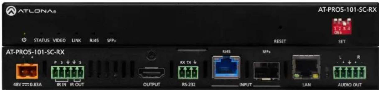
The Atlona AT-PRO5-101-SC-RX is an AV extension receiver with integrated video processing, featuring SDVoE® 10GbE connectivity for receiving ultra-high definition video and audio from the AT-PRO5-MX810 matrix switcher. Part of the PRO5 Series, the PRO5-101-SC-RX is HDCP 2.3 compliant, and supports 4K/60 4:4:4 and HDR at HDMI® data rates up to 18 Gbps. It features an RJ45 port, and an SFP+ cage for copper or fiber optic connectivity to receive video, embedded audio, Gigabit Ethernet, and RS-232 and IR control signals from the matrix switcher. The RJ45 port allows extension up to 330 feet (100 meters) over CAT6a UTP cable, along with PoE for powering the PRO5-101-SC-RX, while the SFP+ cage can be used with a compatible fiber optic module to extend from 38 meters up to 10 kilometers over fiber optic cable. This receiver features high-performance video processing which includes 4K video upscaling and downscaling with frame rate conversion, and video wall processing for 2x2, 1x3, and 2x4 display arrays. The PRO5-101-SC-RX SDVoE scaling receiver, together with the PRO5-MX810 HDMI to SDVoE matrix switcher, is ideal for a wide range of commercial applications requiring multi-zone AV distribution with long-distance signal extension.
Package Contents
1 x AT-PRO5-101-SC-RX
1 x 3-pin captive screw connector
2 x 5-pin captive screw connectors
1 x Insert w/ QR code
Front Panel Descriptions

1 LED Indicators
Displays the current state of the unit:
- PWR - LED will be green when the unit is powered.
- STATUS - LED will be solid green when the signal is encrypted with HDCP. If the signal is not encrypted, the LED will blink green. If no video signal is detected, then the LED will be off.
• VIDEO - LED will be solid green when video is passing through the AT-PRO5-SC-RX. - LINK - LED will be solid green when a link has been established with AT-PRO5-MX810.
- RJ45 - LED will be solid green when the RJ45 port is being used.
- SPF+ - LED will be solid green when and SFP+ module is being used.
2 RESET
Press this recessed button, using a paperclip or other small object, to perform a factory-reset on the unit.
3 SET
These DIP switches control the function of both the RJ45 and SFP+ port. Refer to DIP Switch Settings (page 4) for more information.
Rear Panel Descriptions

1 48V / 0.83A
Connect the included 48 V / 0.83 A power supply from this port to an available AC electrical outlet. Note that the power supply is optional when using the SFP+ port.
2 IR IN / IR OUT
Connect one of the included 5-pin captive screw connectors to this port. Refer to IR IN / IR OUT (page 6) for wiring information.
3 OUTPUT
Connect an HDMI cable from this port to a display.
4 RS-232
Connect the included 3-pin captive screw connector to this port.
5 INPUT
Connect these inputs from the AT-PRO5-MX810, based on the desired extension method. Note that both RJ45 and SFP+ port cannot be used at the same time.
- RJ45 - Provides extension up to 330 feet (100 meters) over CAT6A/7 cable along with Power over Ethernet (PoE).
- SFP+ When used with compatible fiber optic transceiver modules, this port provides extension from 38 meters (125 feet) up to 10 kilometers (6.2 miles) over fiber optic cable.
6 LAN
Connect an Ethernet cable from this port to the network.
7 AUDIO OUT
Connect the included 5-pin captive screw connector from this port to an amplifier.
Installation
- Connect these INPUT ports from the EXT 1 - EXT 8 ports on the AT-PRO5-MX810. Note that both RJ45 and SFP+ port cannot be used at the same time.
-
Optional: Adjust the DIP switches to the desired setting. By default, they are configured to Auto mode, which automatically detects the correct extension type on the back panel. Refer to the DIP Switch Settings table below
-
RJ45 - Connect CAT6a/7 cabling up to 330 feet (100 meters) to AT-PRO5-101-SC-RX scaling receivers or AT-PRO5-101-RX receivers.
-
SFP+ - Fiber optic transceiver modules extend from 38 meters up to 10 kilometers over fiber optic cable. Refer to Compatible Transceivers (page 4) for more information.
-
Connect an HDMI cable from the OUTPUT port to a display.
- Connect an Ethernet cable from the LAN port to the Local Area Network (LAN).
- Connect the included 3-pin captive screw connector from the RS-232 port to the display, if using RS-232 to control the display. Refer to RS-232 (page 5) for more information.
- Connect a 3.5 mm jack from the control system to the IR IN ports. Connect IR emitters from the IR OUT ports to controlled devices.
- Connect the included 5-pin captive screw connectors from these AUDIO OUT ports to an amplifier. Refer to AUDIO OUT (page 5) for more information.
- Optional: Connect the power supply to the 48V / 0.83A receptacle.
DIP Switch Settings
| Function | SW 1 | SW 2 | SW 3 | SW 4 |
| Auto | Up | Up | - | - |
| 10Gb | Up | Down | - | - |
| SFP+ | Down | Down | - | - |
| Ethernet Pass-Through | - | - | Up | - |
| Ethernet Control | - | - | Down | - |
NOTE: The “-” symbol indicates that the switch can be in either up or down for that function.

RS-232
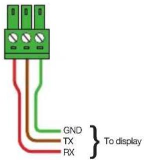
Connect the RS-232 cable between the RS-232 port on the AT-PRO5-101-SC-RX and the display. Use the included 3-pin captive screw connector to wire the RS-232 cable as shown.

AUDIO OUT
Each AUDIO OUT port can be wired for either unbalanced or balanced output. For unbalanced audio connections, both negative terminals should be connected to ground. Wire the included 5-pin captive screw connectors as shown.


Unbalanced Audio

Balanced Audio
IR IN / IR OUT
Connect the IR sensor and an IR emitter to the IR IN / IR OUT port on the AT-PRO5-101-SC-RX. Use the included 3-pin captive screw connector for the IR receiver (IR IN) and the included 2-pin captive screw connector to connect the IR emitter (IR OUT).


Notes
Warranty
To view the product warranty, use the following link or QR code: https://atlona.com/warranty/.

English Declaration of Conformity
The English version can be found under the resources tab at: https://atlona.com/product/at-pro5-101-sc-rx/.

Chinese Declaration of Conformity 中国RoHS合格声明
由SKU列出於:
https://atlona.com/about-us/china-rohs/.


The terms HDMI, HDMI High-Definition Multimedia Interface, HDMI trade dress and the HDMI Logos are trademarks or registered trademarks of HDMI Licensing Administrator, Inc.

ATLONA.
a Payout company
US International
atlona.com • 408.962.0515 • 41.43.508.4321
© 2025 Atlona Inc. All rights reserved. "Atlona" and the Atlona logo are registered trademarks of Atlona Inc. All other brand names and trademarks or registered trademarks are the property of their respective owners. Pricing, specifications and availability subject to change without notice. Actual products, product images, and online product images may vary from images shown here.
Brand : Atlona
Model : AT-PRO5-101-SC-RX
Category : AV receiver