
XHB554 - TV Peerless-AV - Free user manual and instructions
Find the device manual for free XHB554 Peerless-AV in PDF.


| Product Type | TV Display |
| Brand | Peerless-AV |
| Model | XHB554 |
| Screen Size | 55 inches |
| Mounting Pattern | VESA 400x200mm, 400x400mm; Alternate 600x600mm, 850x600mm |
| Mounting Screw Size | M8 x 18mm max (VESA 400mm); M8 x 12mm max (Alternate) |
| Orientation | Landscape or Portrait (90° rotation) |
| Power Requirements | 100-240V AC, 50-60Hz |
| Operating Temperature | -35°C to 60°C (-31°F to 140°F) |
| Compliance | FCC Class A, Part 15 |
| Safety Features | UL listed external surge protection; grounded outlet; drip loop for cables |
| Airflow Requirements | Minimum 2 inches (51mm) sides, 4 inches (102mm) top/bottom; increased spacing for multiple units |
| Cleaning Instructions | Unplug power; do not spray water >100kPa; use soft cloth; avoid harsh pressure |
| Sensor Window Location | Top left in landscape; top right in portrait |
| Image Retention Prevention | Avoid static images for >20 minutes |
Frequently Asked Questions - XHB554 Peerless-AV
User questions about XHB554 Peerless-AV
0 question about this device. Answer the ones you know or ask your own.
Ask a new question about this device
Download the instructions for your TV in PDF format for free! Find your manual XHB554 - Peerless-AV and take your electronic device back in hand. On this page are published all the documents necessary for the use of your device. XHB554 by Peerless-AV.
USER MANUAL XHB554 Peerless-AV
SYSTEM INSTALLATION AND ELECTRICAL REQUIREMENTS
Electrical Code
Note: To the display system installer: This reminder is provided to call attention to Article 820-44 of the National Electric Code that provides guidelines for proper grounding and, in particular, specifies that the cable ground shall be connected to the grounding system of the facility. Outlet shall be installed near the equipment and shall be easily accessible.

Note: Installation shall incorporate UL Listed external surge protection rated 2500 Vpk or less, for 150 to 300 Vac mains, installed in accordance with Article 285 of ANSI/NFPA 70 or applicable local codes.
Power Source
The display must be connected to a mains socket outlet with a protective grounding connection.
The mains plug is used as the disconnect device and shall remain readily accessible.
Electrical installation shall be in accordance with the applicable parts of Chapter 8 of ANSI/NFPA 70.
An outdoor antenna should not be located near overhead electrical lines or any electrical circuits.
If an outside antenna is connected to the receiver, confirm that the antenna system is grounded to protect against voltage surges and built up static charges. Section 810 of the National Electric Code, ANSI/NFPA No 70-1984, provides information with respect to proper grounding for the mast and supporting structure, grounding of the lead-in wire to an antenna discharge unit, size of grounding connectors, location of antenna discharge unit, connection to grounding electrodes and requirements for the grounding electrode.
This display operates on 100-240 volts 50-60 Hz, AC current. Never connect the display to direct current or anything other than the specified voltage.
To prevent electric shock from the display, do not use with an extension cord, receptacle, or other outlet unless the blades and ground terminal can be fully inserted to prevent blade exposure.
All secondary lines must be routed through grounded conduit and kept separate from AC line.
FCC CAUTION
To assure continued compliance and possible undesirable interference, ferrite cores may be used when connecting this display to video equipment; maintain at least 400mm (15.75 inches) spacing to other peripheral devices.
FCC STATEMENT
This equipment has been tested and found to comply with the limits for a Class A digital device, pursuant to Part 15 of the FCC Rule. These limits are designed to provide reasonable protection against harmful interference in a residential installation. This equipment generates, uses and can radiate radio frequency energy and, if not installed and used in accordance with these instructions, may cause harmful interference to radio communications; however, there is no guarantee that interference will not occur in a particular installation. If this equipment does cause harmful interference to radio or television reception, which can be determined by turning the equipment off and on, the user is encouraged to try to correct the interference by one or more of the following measures:
- Reorient or relocate the receiving antenna.
- Increase the separation between the equipment and receiver.
- Connect the equipment into an outlet on a circuit different from that to which the receiver is connected.
- Consult the dealer or an experienced radio/display technician for help.
This device complies with Part 15 of the FCC Rules. Operation is subject to the following two conditions:
- This device may not cause harmful interference.
• This device must accept any interference received, including interference that may cause undesired operation.
Relevant Information
Record your display's model and serial number here for future reference. Keep this user manual in an accessible location in the event service is required. Note: Your display's serial number can be found on the box, underneath the rear cover plate, and in the Setup Menu under Peerless-AV Technical Support.
Model Number
Serial Number
GENERAL SAFETY PRECAUTIONS
Read before operating equipment
Thank you for purchasing our product. Before using it, please read this user guide carefully and follow the instructions for safe operation. Please keep this manual for future reference and always include it when transferring or transporting this product to a different location.
WARNING
In case of emergency such as fire or electric shock caused by the product, immediately contact 911 or proper emergency police/fire service agencies in your country.
To reduce the risk of electric shock or fire, heed the following:
- In case of product malfunction or unusual events such as electrical burning smell, smoke, or loss of content signals due to internal overheating, immediately turn off, unplug the electrical cord and contact the manufacturer.
- Do not disassemble, modify or service product in any way other than that contained in this instruction. Any unauthorized modifications made to the product automatically void product warranty.
- Do not touch antenna lines or wires, electrical cables or plugs when lightning or thunder is present or with wet hands.
- Do not submerge in water.
- Do not destroy, process, or place close to any heat source.
- Do not install near poisonous gas or chemically unstable atmosphere.
- Do not install near strong magnetic or electrical current field.
- Do not install the product in unstable locations or near moving objects, constantly vibrating equipment, or uneven surfaces.
- Do not leave any fire source, such as candles, close to or on the product.
- Do not operate the product if it has been dropped or struck. Severe physical impact to the product may cause components to fall out of place within and break.
- Do not bend or twist electrical cords, electrical plugs, cables, or wires with excessive force.
- Do not block ventilation slots or place any heavy object on the product.
- Use properly rated electrical voltage.
- Do not use any electrical sockets or power strips with many other devices jointly plugged in. Use a single, directly dedicated and rated GFCI electrical outlet for the product for safe operation.
- Do not move or transport with any cables (electrical, content connectivity) plugged in to the source devices.
- Always connect the electrical plug firmly and completely. When disconnecting any cables, always pull on the plug and not the cord.
- Always leave the power off when plugging or unplugging the electrical cords or connection cables.
- Do not defeat the safety purpose of the polarized or grounding type electrical plug. A polarized plug has two blades with one wider than the other. A grounding type plug has two blades and a third grounding prong. The wide blade or the third prong are provided for your safety. If the provided plug does not fit into your outlet, consult an electrician for replacement of the obsolete outlet.
- Protect the electrical cord from being walked on or pinched particularly at plugs, convenience receptacles, and the point where they exit from the apparatus.
WARNING
- Never apply pressure to the exterior of the LCD screen.
- If monitor or glass is broken, do not come in contact with the liquid crystal and handle with care.
- Do not climb on the product.
- Do not install within five feet from a body of water.
- Do not use if ambient air temperature exceeds the operating limits; Maximum operating temperature is -31^ 140^ (-35°C \~ 60°C).
- High solar loads may require reducing maximum operation temperature up to 14^ or 10^ to reduce the possibility of temporary screen artifacts.
- Do not install in enclosure or recessed cavity with less than 2 inches of airflow around the display. Air inside fully encased display must be ventilated. Installations within any third party enclosure without written authorization from Peerless-AV are not covered by the Peerless-AV Limited Warranty, nor any extended warranty.
- When installing in an enclosure or recessed cavity, the internal temperatures of those locations must not exceed the maximum operating temperatures as listed above.
- The product is to be secured to building before operation.
- Product must be carried and supported by at least two persons.
- Periodically clean dust off the electrical plug to keep it clean and dry, ensuring proper and safe operation.
- Only use attachments/accessories specified by the manufacturer.
CAUTION
To avoid image retention/burn-in on the LCD screen, do not allow static images to display for longer than 20 minutes at a time. Image retention is considered improper use of an LCD and is not covered by the Peerless-AV Limited Warranty, nor any extended warranty.
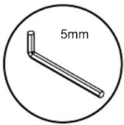
Tools Needed for Assembly.
Installation Locations
Follow local codes for environmental requirements.
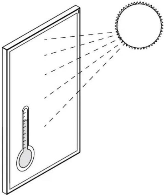
If installed in extremely hot locations, ensure ambient temperature does not exceed operating temperature of the display. Be aware that sun exposure times over 3 hours can elevate the display's internal temperature by an additional 30^ C over ambient temperature.
The end user/installer must note the potential for temperature-increase based on high thermal/solar load, which needs to be addressed with additional cooling measures. Please contact Peerless-AV for design consultation in such cases.
natural_image
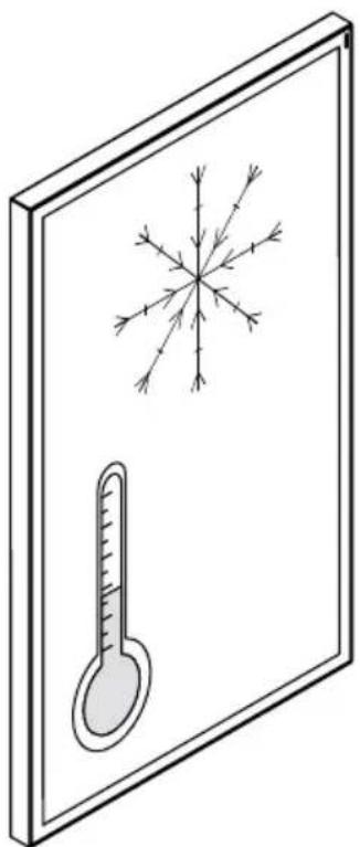
Diagram showing a thermometer inside a mirror with a sun emitting rays, illustrating thermal imaging or temperature measurement (no text or symbols present)If installed in extremely cold locations, the end user/installer must note the potential for temperature-decrease based on environmental conditions and note that until display reaches operating temperature, display may experience performance lag.
natural_image
Illustration of a thermometer and snowflake on a wall, no text or symbols presentUse this graph to estimate solar load and its effect on maximum safe ambient temperature for the display.

line
| Solar Load (W/m²) | Temperature (°C) | | ----------------- | ---------------- | | 0 | 60 | | 200 | 60 | | 300 | 59 | | 400 | 58 | | 500 | 57 | | 600 | 56 | | 700 | 55 | | 800 | 54 | | 900 | 53 | | 1000 | 52 | | 1100 | 51 | | 1200 | 50 |Kiosks will incur an additional 5^ C minimum temperature rise with the disclaimer that insufficient airflow, high surface area to volume ratio, additional internal electronics, and dark exterior colors will incur a higher temperature rise. Peerless-AV Engineering should be consulted in these situations.
Peerless-AV Engineering must be consulted before placing the display into any enclosure not developed by Peerless-AV. Peerless-AV Engineering management must approve this installation solution to support the native warranty of the display.
This page intentionally left blank.
Display Orientation
Display can be oriented in landscape or portrait. Rotate display 90^ clockwise to change to portrait orientation. Rotate display 90^ counterclockwise to switch back to landscape orientation. When in landscape orientation, the sensor window will be on the top left of the display. When in portrait orientation, the sensor window will be on the top right of the display.


Do not block the sensor window. If window is blocked, consult with Peerless-AV for proper IR extender (included with product) and ALS extender usage (sold separately).
Prepare the Display for Mounting
Install cords prior to mounting your display. Input panel may be obstructed once the display is mounted.
A mounting solution is sold separately. Contact your Peerless-AV representative for an outdoor rated mounting solution for your particular application.
For your safety, only install an outdoor-rated mount that is suitable for the application and supports the weight of the display. When mounting a display outdoors, use proper environmentally rated mounts to ensure longevity in harsh environments.
Examine the chart below to determine the mounting specifications for your display:
| Display Size | Mounting Hole Pattern Mounting Screw Size | |
| 55" | VESA 400 x 200mmVESA 400 x 400mm | Four M8 x 18mm maximum thread |
| Alternate 600 x 600mmAlternate 850 x 600mm | Four M8 x 12mm maximum thread | |
| Display Size | A B C D E | F G H I | |||||||
| 55" | 15.75"(400mm) | 15.75"(400mm) | 17.16"(436mm) | 6.74"(171mm) | 3.92"(100mm) | 7.87"(200mm) | 23.62"(600mm) | 23.62"(600mm) | 33.46"(850mm) |

BACK VIEW
Removing Handles (Optional)


CAUTION
Do not remove the screws above or below the handles. Failure to follow these instructions can result in the product being damaged or destroyed, voiding the warranty.
Landscape Mounting
Landscape oriented displays use a 400 x 400mm VESA mounting pattern.

Portrait Mounting
Portrait oriented displays can use either 400mm x 400mm VESA mounting patterns on the raised portion of the rear surface. Note, this may limit access to removable input cover. Installers can also use either a 600 x 600mm mounting pattern or the 600 x 850mm perimeter mounting locations.
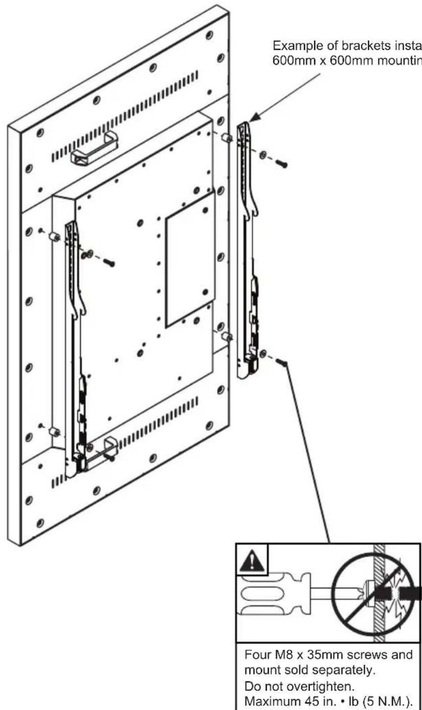
For portrait or landscape oriented displays, the maximum downward tilt is 15^ . For other orientations, consult Peerless-AV.

LANDSCAPE PORTRAIT
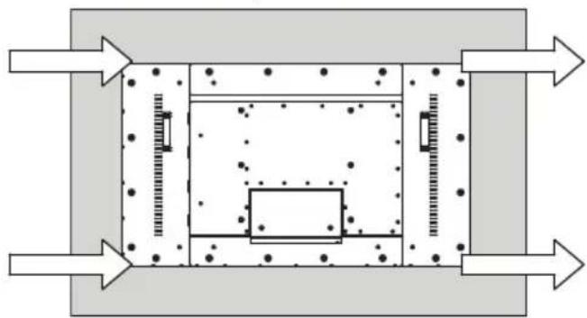
Minimum Airflow Spacing
Consult Peerless-AV for minimum spacing when installing two or more adjacent displays. Note: These are minimum requirements. Internal heat sources due to additional equipment, external heat sources and high solar loads may require additional spacing and airflow. Please consult Peerless-AV for additional guidance.
| W X1 | X2 Y1 Y2 | |||
| 4" (102mm) | 2" (51mm) | 2" (51mm) | 4" (102mm) | 2" (51mm) |


Minimum Airflow Spacing
Consult Peerless-AV for minimum spacing when installing two or more adjacent displays. Note: These are minimum requirements. Internal heat sources due to additional equipment, external heat sources and high solar loads may require additional spacing and airflow. Please consult Peerless-AV for additional guidance.
| WX Y1 Y2 | ||
| 8" (203mm) 2" (51mm) 4" (102mm) 2" (51mm) | ||

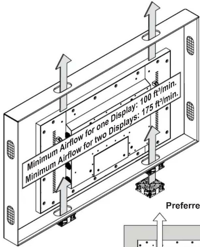
Airflow, Venting and Heat Dissipation
Consult Peerless-AV when installing two or more adjacent displays. Note: These are minimum requirements. Internal heat sources due to additional equipment, external heat sources and high solar loads may require additional spacing and airflow. Please consult Peerless-AV for additional guidance.
Preferred

natural_image
Pure schematic diagram of a mechanical or structural assembly with no text, numbers, or symbolsCAUTION
Do not impede airflow by blocking ventilation holes.

natural_image
Illustration of a wall-mounted device with grass and a coiled cable beside it (no text or symbols)Optional
natural_image
Pure schematic diagram of a rectangular chamber with internal components and directional arrows, no text or symbols present.Airflow, Venting and Heat Dissipation
Consult Peerless-AV when installing two or more adjacent displays. Note: These are minimum requirements. Internal heat sources due to additional equipment, external heat sources and high solar loads may require additional spacing and airflow. Please consult Peerless-AV for additional guidance.


CAUTION
Do not impede airflow by blocking ventilation holes.

natural_image
Illustration of a wall-mounted device with grass and a coiled cable beside it (no text or symbols)Routing Cables in the Display
Use only high-quality, shielded, grounded cables.

flowchart
graph TD
    A["media device"] --> B["drip/service loop"]
    C["media device"] --> D["drip/service loop"]
    style A fill:#f9f,stroke:#333
    style C fill:#f9f,stroke:#333
    style B fill:#ccf,stroke:#333
    style D fill:#ccf,stroke:#333

Replacing Cord Cover
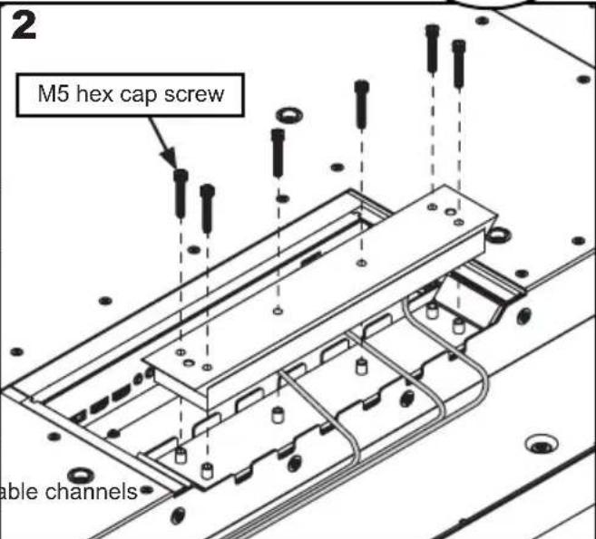
- Run power and signal cords through separate cable channels to prevent unwanted interference. Route the power cord through the right most cable channel. (see image 1 below).
- Replace the cord cover ensuring the cords are running through the cable channels and not getting pinched. Loosely install six M5 hex cap screws, then tighten using 3mm allen wrench until the cover gasket is fully compressed to the cord gasket.
- Replace the rear cover plate ensuring the cords are running through the cable channels and not
getting pinched. Fasten the two hex screws on the rear cover plate using 3mm allen wrench to secure. Ensure the rear cover plate is fully compressed to the back of the display.

natural_image
Simple line drawing of a bent rod inside a circle with letter E (no text or symbols on the object itself)
CAUTION
Failure to follow these instructions can result in the product being damaged or destroyed, voiding the warranty.
Optional: cable management


natural_image
Technical line drawing of a mechanical assembly with mounting holes and internal components (no text or symbols)CAUTION
- Ensure cord bend radius does not exceed limits set by the manufacturer.
- Ensure cords are seated properly in the cable channels to avoid potential damage to cords when rear cover plate is installed.
- Do not remove lanyard that connects the rear cover plate to the display.
- Ensure cables exiting input compartment are routed downward when installing display in portrait orientation. If the installation requires the cabling to be routed upward, ensure that the cables are routed with a drip loop.

Do not overtighten screws.
Cleaning the Screen
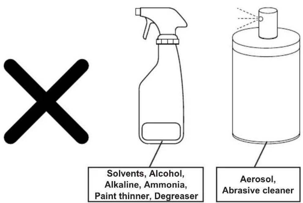
Do not rub or strike the screen with anything hard as this may scratch, mark, or even damage the screen permanently. Unplug the power cord before cleaning the screen. Do not spray water on the display in excess of 100kPa (14.5 PSI).

This page intentionally left blank.
This page intentionally left blank.
This page intentionally left blank.
www.peerless-av.com/warranty
peerless-AV®
Peerless-AV
2300 White Oak Circle
Aurora, IL 60502
Email: tech@peerlessmounts.com
Ph: (800) 865-2112
Fax: (800) 359-6500
www.peerless-av.com
Peerless-AV Europe
Unit 3 Watford Interchange,
Colonial Way, Watford, Herts,
WD24 4WP, United Kingdom
Customer Care
44 (0) 1923 200 100
www.peerless-av.com
Peerless-AV América Latina
- SYSTEM INSTALLATION AND ELECTRICAL REQUIREMENTS
- Electrical Code
- Power Source
- FCC CAUTION
- FCC STATEMENT
- Relevant Information
- GENERAL SAFETY PRECAUTIONS
- Read before operating equipment
- WARNING
- CAUTION
- Installation Locations
- Display Orientation
- Prepare the Display for Mounting
- Removing Handles (Optional)
- Landscape Mounting
- Portrait Mounting
- Minimum Airflow Spacing
- Airflow, Venting and Heat Dissipation
- Routing Cables in the Display
- Replacing Cord Cover
- Cleaning the Screen
- www.peerless-av.com/warranty
- peerless-AV®
- Peerless-AV
- Peerless-AV Europe
- Peerless-AV América Latina
Brand : Peerless-AV
Model : XHB554
Category : TV