
WAERO - Headset with mic CAME-TV - Free user manual and instructions
Find the device manual for free WAERO CAME-TV in PDF.


| Product Type | Wireless Video Transmitter & Receiver System |
| Model | WAERO |
| Brand | CAME-TV |
| Dimensions (Transmitter) | 100 x 60 x 30 mm |
| Dimensions (Receiver) | 100 x 60 x 30 mm |
| Weight (Transmitter) | 150 g |
| Weight (Receiver) | 150 g |
| Power Input | DC 7-17 V |
| Battery Compatibility | Sony NP-F series |
| Video Resolution | 1080p up to 60 fps |
| Transmission Range | Up to 500 m (line of sight) |
| Latency | < 0.1 seconds |
| Video Input/Output | HDMI, SDI |
| Frequency Band | 5 GHz |
| Channel Selection | Auto or manual (up to 16 channels) |
| Display | OLED on transmitter and receiver |
| Cooling | Built-in fan |
| Mounting | 1/4"-20 threaded hole, cold shoe |
| Maintenance | Clean with dry cloth; avoid dust buildup |
| Safety | Do not expose to moisture; use only approved power supplies |
| Spare Parts Available | Antennas, power cables, mounting brackets |
| Repairability | Modular design with replaceable components |
Frequently Asked Questions - WAERO CAME-TV
User questions about WAERO CAME-TV
0 question about this device. Answer the ones you know or ask your own.
Ask a new question about this device
Download the instructions for your Headset with mic in PDF format for free! Find your manual WAERO - CAME-TV and take your electronic device back in hand. On this page are published all the documents necessary for the use of your device. WAERO by CAME-TV.
USER MANUAL WAERO CAME-TV
WAERO
USER MANUAL
V 2.4.1
The CAME-TV WAERO Duplex Digital Wireless Foldable Headset is easy to set up and provides about 366m/1200ft of open range between the Master and Remote headsets. There are two versions available, US for the US while EU for EU countries and other countries can use either version if it does not have the regulation on frequency use. This manual applies to model WAERO-R(Remote) and WAERO-M(Master).
Parameters
| Standard DECT technology, GAP compatible | |
| Range 1200ft (366 Meters) in open space | |
| Talk Time Master 10 Hours; Remote 13 Hours | |
| Channel Bandwidth 1.728MHz | |
| Modulation Type GFSK | |
| Duplex Operation Time Division Duplex (TDD) | |
| CE Frequency 1881.792-1897.344 MHz | |
| FCC Frequency 1920-1930 MHz | |
| MIC Frequency 1895.616-1902.528 MHz |
Quick Start Guide
Install the batteries correctly into the battery compartments of the master and remote, and the device will automatically power on and be ready for use.
Voice +: Raise the volume

Power on / off
Voice -: Lower the volume

Red indicator: Master

Blue indicator: Remote
Operating Instructions
1. Power On/Off
Power on: the headset will be powered on automatically when battery is installed. In the condition that battery is already in its compartment, one quick press the power button to turn on the headset.
Power off: Press and hold the power button for around 5 seconds until power indicator changes off.
Note: Power off the remote headsets first otherwise the master headset can not be powered off.
2.LED Indicators
Master: red LED on earcup indicates master headset.
Remote: blue LED on earcup indicates remote headset.
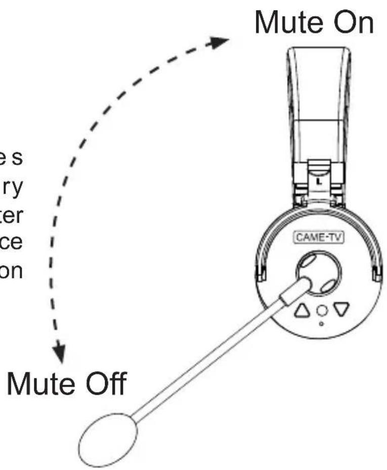
3.Microphone Boom
MUTE OFF: When microphone boom is in down position, you can talk and listen.
MUTE ON: Flip the boom microphone up, it mutes the microphone only and you can still hear what everyone else is saying.
4. Volume
Voice +: Raise the volume
Voice -: Lower the volume
How to Optimize the Communication Effect
- In order to get the best communication result, it is recommended to place the master (or HUB) in the center position, and the remotes are arranged around the master (or HUB) to ensure that each remote is within the working distance.
- If there is both a master headset and a HUB, the distance between master and the HUB should also be kept within an appropriate distance within 1200ft. Also, it is important to distinguish which remote headsets are paired with the master and which remote headsets are paired with the HUB. If a remote headset paired with the master exceeds the working range of the master, even if it is close to the HUB, it will not be able to talk.

![graph TD A["A"] --> B["B"] A --> C["C"] A --> J["J"]](/content/2026/05/1015504/images/2619d773d5356cafc9f0140414e62ed210e5a0db7c7ec9219345f0ef67a1516b.jpg)

Master
BCJ
Remote

![graph TD A["A"] --> HUB["HUB"] HUB --> M2["M2"] HUB --> R["R"] HUB --> M1["M1"] M2 --> G["G"] M2 --> H["H"] M2 --> I["I"] M1 --> D["D"] M1 --> E["E"] M1 --> F["F"]](/content/2026/05/1015504/images/442a8929a728309b68dccce96daad8f109d9a1e746e104568ff1eb46940ad07b.jpg)


![graph TD A["A"] --> B["B"] A --> C["C"] HUB["HUB"] --> M1["M1"] HUB --> M2["M2"] M1 --> R["R"] M2 --> G["G"] M2 --> H["H"] M2 --> I["I"] M1 --> D["D"] M1 --> E["E"] M1 --> F["F"]](/content/2026/05/1015504/images/6b9a045afed158846b7cc2b2a275a03c723ac5007f1716ef267e1577042a0e39.jpg)

6 Person Talking in One Group or Split into Two Groups (Each Group Four Person)
![graph TD A["Master A M"] --> B["Headphones"] A --> C["Headphones"] A --> D["Headphones"] A --> E["Headphones"] A --> F["Headphones"] G["Master A M"] --> H["Headphones"] G --> I["Headphones"] G --> J["Headphones"] G --> K["Headphones"] G --> L["Headphones"] M["Master A M"] --> N["3.5mm Audio Cable"]…](/content/2026/05/1015504/images/0122d8e7355352b4f60cf3da9c1434624a63d353e64fac554105b5ec894449b3.jpg)
Expanding to 18 Person Talking or Split into 2/3/4 Different Groups
![graph TD A["Headsets"] --> B["Master A"] C["Headsets"] --> B D["Headsets"] --> B E["Headsets"] --> B F["Headsets"] --> B G["Headsets"] --> B H["Headsets"] --> B I["Headsets"] --> B J["Headsets"] --> B K["Headsets"] --> B L["Headsets"] --> B M["Headsets"] --> B N["Headsets"] --> B O["Headsets"] --> B…](/content/2026/05/1015504/images/4e3d8db12908cb30ba42602bca29f567b0880dcb9152cd41e7fdf20931749f37.jpg)
The Hub incorporates two Masters and one built-in Remote.
Each Master within the Hub can accommodate up to 3 Remotes.
With this configuration, a single hub enables connections for up to 9 headsets within a single system, while two hubs can facilitate connections for up to 14 headsets.
(Please refer to the pairing diagram above for further guidance.)
The hub has a micro USB port to power/charge the unit via 5V DC with a USB power supply or power bank.
When power is connected it can run directly without batteries and also charge when batteries are installed. The Hub can run alone on batteries and with one installed run time is about 8-10 hours and with two batteries installed, the run time increases to about 15-18 hours.
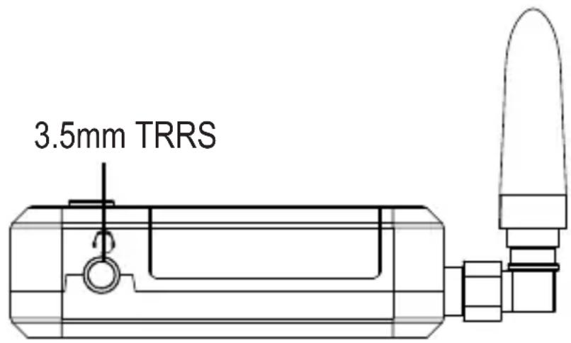
3.5mm TRRS audio jack It adheres to the United States CTIA standard.
If your equipment follows the OMTP standard, you will need to use a conversion cable.
USB Function
- Direct Power Supply to the HUB
- Charge batteries in the battery compartment.

USB 5V Switch button

1 Working indicator for M1 group 2 Working indicator for HUB remote
3 Working indicator for M2 group 4 Master 1 button
5 Remote button Master 2 button 6
7 Charging indicator 8 Power indicator
9 Charging indicator Battery compartment
As long as an NB-6L battery is present in the battery compartment, it will constantly supply power to the hub.
If there is no battery, the hub can also be connected to an external power supply through the USB port.
With an external USB power supply, the HUB can also charge the batteries placed inside it.

Working Indicator for M1 and M2
The working indicator aids in distinguishing the Master to which the remote belongs.
When viewed vertically from the top, the M1 and M2 indicators display the number of remotes they are connected to, with each Master capable of connecting to up to 3 remotes.
Consequently, up to 6 indicators can illuminate simultaneously.
If a remote powers off or disconnects, the corresponding indicator will extinguish. For instance, if one of the remotes connected to M1 powers off, only two of M1's indicators will remain lit, while M2's indicators will remain unaffected.
The product comes pre-paired, allowing immediate use upon switching on the device without any additional steps. Pairing becomes necessary only if a remote loses connection with the master.
WAERO Pairing Steps
① Ensure that both the Master and all Remote devices are powered on. When the Master enters the pairing state, any Remotes not powered on will be cleared from the set.
② Make sure to mute off the microphone. (The LED indicator light will flash slowly when mute is on, which may disrupt the pairing procedure.)
③ Simultaneously press the Volume Up and Down keys on the Master until the Red LED indicator begins flashing quickly, indicating it has entered the pairing state. Remote headsets share the same pairing activation steps by simultaneously press volume up and down button. Start by pairing one Remote, then proceed to pair the remaining lost Remotes one by one in sequence. The newly connected Remotes can be powered on without any additional steps.
④ The Master will automatically exit the pairing state and the LED will become solid once it is fully connected with all 3 Remotes. If there are fewer than 3 Remotes, you can manually exit the pairing state by pressing the Master Headset power button. If you want to pair a Remote with a new Master, be sure to turn off the previous Master that was paired with that Remote before initiating the new pairing process.
These are precise pairing procedures. It is strongly recommended to follow the guide carefully and accurately for successful operation of this unit.
Pairing
The product comes pre-paired, allowing immediate use upon switching on the device without any additional steps. Pairing becomes necessary only if a remote loses connection with the master.
It is important to check the disconnected remote ID number to identify which group master it belongs to:
- Master A group (Remote Hub R and Remote B/C)
- Hub M1 group (Remote D/E/F)
- Hub M2 group (Remote G/H/I)
Make sure to pair the disconnected group only. Ensure that both the master and all remote devices in the disconnected group are powered on. When the Master enters the pairing state, any remotes not powered on in the same group will be cleared.
**Pairing Steps for Different Group Remotes:**
① Pairing Master A with Remote Hub R and Remote headsets B/C: (In below two circumstances, make sure Master A, Remote Hub R, and Remote headsets B/C are powered on.)
If it is Remote B/C/J disconnected from Master A:
- Activate the pairing mode of Master A by pressing the "Volume Up" and "Volume down" buttons simultaneously, once the LED indicator starts flashing quickly and the sound of "pairing" is heard, indicating it has entered the pairing state. And then activate the pairing mode of lost remote headset. Start by pairing one remote, once it says "your headset is connected" then proceed to pair the remaining lost remotes one by one in sequence.
If it is Remote Hub R disconnected from Master A:
- Press the Volume Up and Down keys simultaneously on Master A until the LED indicator starts flashing quickly to enter the pairing state.
-Press and hold the middle button on remote Hub R until the Blue LED indicator starts flashing quickly to enter the pairing state.
-Once they are successfully connected with each other, the working indicator for hub remote R will become solid. The Master A will automatically exit the pairing state and the LED will become solid once it is fully connected with 3 Remotes(Remote Hub R and Remote headsets B/C). If there are fewer than 3 remotes, you can manually exit the pairing state by pressing the master A mute button.
**Pairing Steps for Different Group Remotes:**
② Pairing the Hub M1 group (Remote D/E/F):
- Ensure that both the Hub M1 and all Remote D/E/F are powered on.
- Press and hold the left button on Hub M1 until the blue LED indicator starts flashing quickly to enter the pairing state.
Simultaneously press the "Volume Up" and "Volume Down" buttons on the disconnected remote Nano until the LED starts flashing quickly, you will hear the sound of pairing from the remote. Begin by pairing one remote first, then proceed to pair the remaining lost remotes one by one in sequence.
- Hub M1 will automatically exit the pairing state, and the LED will become solid once it is fully connected with 3 remotes (Remote D/E/F). If there are fewer than 3 remotes, you can manually exit the pairing state by long-pressing the HUB M1 button.
③ Pairing the Hub M2 group (Remote G/H/I):
- Ensure that both the Hub M2 and all Remote I/H/G are powered on.
- Long-press the Hub M2 button to activate the pairing process. The procedure is similar to the step above.
① The Master module and remote module in the hub cannot be paired at the same time, as it may result in malfunction.
② It is crucial to identify the group that the disconnected remote belongs to before pairing.
③ Pairing is only needed for the disconnected group, and ensure that all remotes in the same group are powered on before pairing.
FCC Regulatory Compliance
This device complies with Part 15 of the FCC Rules.
Operation is subject to the following two conditions:
(1) this device may not cause harmful interference, and (2) this device must accept any interference received including interference that may cause undesired operation.
Warning: changes or modifications not expressly approved by the party responsible for compliance could void the user's authority to operate the equipment.
Note: This equipment has been tested and found to comply with the limits for a Class B digital device, pursuant to Part 15 of the FCC Rules. These limits are designed to provide reasonable protection against harmful interference in a residential installation. This equipment generates, uses and can radiate radio frequency energy and, if not installed and used in accordance with the instructions, may cause harmful interference to radio communications. However, there is no guarantee that interference will not occur in a particular installation.
If this equipment does cause harmful interference to radio or television reception, which can be determined by turning the equipment off and on, the user is encouraged to try to correct the interference by one or more of the following measures:
--Reorient or relocate the receiving antenna.
--Increase the separation between the equipment and receiver.
--Connect the equipment into an outlet on a circuit different from that to which the receiver is connected.
--Consult the dealer or an experienced radio/TV technician for help.
FCC RF Radiation Compliance
The device has been tested and comply with FCC SAR limits.
This transmitter must not be co-located or operating in conjunction with any other antenna or transmitter.
While we trust you will never have the need, if you do, our service is both friendly and hassle-free.
Email:
Americas: americas@came-tv.com Outside Americas: europe@came-tv.com
Follow Us:
https://www.facebook.com/CameTvGear/ https://www.instagram.com/cametv/ https://www.youtube.com/c/CameTVgear/videos https://www.twitter.com/CameTV
- WAERO
- QUICK START GUIDE
- OPERATING INSTRUCTIONS
- POWER ON/OFF
- 2.LED INDICATORS
- 3.MICROPHONE BOOM
- VOLUME
- HOW TO OPTIMIZE THE COMMUNICATION EFFECT
- USB FUNCTION
- WORKING INDICATOR FOR M1 AND M2
- WAERO PAIRING STEPS
- PAIRING
- PAIRING STEPS FOR DIFFERENT GROUP REMOTES
- IF IT IS REMOTE B/C/J DISCONNECTED FROM MASTER A
- IF IT IS REMOTE HUB R DISCONNECTED FROM MASTER A
- FCC REGULATORY COMPLIANCE
- FCC RF RADIATION COMPLIANCE
- FOLLOW US
Brand : CAME-TV
Model : WAERO
Category : Headset with mic