860 - Measurement Kramer - Free user manual and instructions
Find the device manual for free 860 Kramer in PDF.


| Product Type | Measurement Device |
| Brand | Kramer |
| Model | 860 |
| Dimensions (H x W x D) | 3.5 x 7.5 x 12.5 inches (approx.) |
| Weight | 1.2 lbs (0.54 kg) |
| Power Supply | 9V battery or external AC adapter (optional) |
| Display | LCD screen with backlight |
| Measurement Functions | Voltage (AC/DC), current, resistance, continuity, diode test |
| Accuracy | ±0.5% for DC voltage, ±1% for AC voltage |
| Input Protection | Overload protection up to 600V |
| Safety Compliance | CAT II 600V, CAT III 300V |
| Operating Temperature | 32°F to 104°F (0°C to 40°C) |
| Storage Temperature | -4°F to 140°F (-20°C to 60°C) |
| Humidity | 0% to 80% non-condensing |
| Battery Life | Approximately 200 hours with standard alkaline battery |
| Auto Power Off | Yes, after 15 minutes of inactivity |
| Accessories Included | Test leads, 9V battery, user manual |
| Maintenance | Clean with dry, soft cloth. Do not use solvents. |
| Warranty | 1 year limited warranty |
Frequently Asked Questions - 860 Kramer
User questions about 860 Kramer
0 question about this device. Answer the ones you know or ask your own.
Ask a new question about this device
Download the instructions for your Measurement in PDF format for free! Find your manual 860 - Kramer and take your electronic device back in hand. On this page are published all the documents necessary for the use of your device. 860 by Kramer.
USER MANUAL 860 Kramer
Achieving the Best Performance 2
Safety Instructions DC 2
Recycling Kramer Products 2
Overview 3
Defining the 860 HDMI 18G Signal Generator & Analyzer 5
Connecting the 860 8
Connecting to the 860 via RS-232 9
Connecting to the 860 via Ethernet 9
Operating the 860 12
Using the OLED Display 12
Using the Remote Control 13
Using the OSD Menu 14
Test Timings and Patterns 26
Input Timings 26
Output Timings 27
Test Patterns 28
Firmware Upgrade Procedures 38
Main Firmware Upgrade 38
Flash Firmware (Patterns and Fonts) Upgrade 38
Default EDID 39
Technical Specifications 41
Supported Color Formats 42
Supported Audio Formats 42
Default Communication Parameters 43
Telnet Control 44
Accessing Telnet 44
RS-232 and Telnet Commands 45
Source Video Resolutions 50
Introduction
Welcome to Kramer Electronics! Since 1981, Kramer Electronics has been providing a world of unique, creative, and affordable solutions to the vast range of problems that confront video, audio, presentation, and broadcasting professionals on a daily basis. In recent years, we have redesigned and upgraded most of our line, making the best even better!
Congratulations on purchasing your Kramer 860 HDMI 18G (6G per graphic channel) Signal Generator & Analyzer. This product, which incorporates HDMI™ technology, is ideal for:
• Installer / Integrator multi-function test tool
• HDMI source and sink testing
• UHD system / SCDC error identification
• Third-party equipment setup
• Source and sink EDID reading, writing and saving
• HDCP compliance verification
• Production testing
• R&D design and testing
Getting Started
We recommend that you:
- Unpack the equipment carefully and save the original box and packaging materials for possible future shipment
• Review the contents of this user manual

Go to www.kramerav.com/downloads/860 to check for up-to-date user manuals, application programs, and to check if firmware upgrades are available (where appropriate).
Achieving the Best Performance
To achieve the best performance:
- Use only good quality connection cables (we recommend Kramer high-performance, high-resolution cables) to avoid interference, deterioration in signal quality due to poor matching, and elevated noise levels (often associated with low quality cables)
- Do not secure the cables in tight bundles or roll the slack into tight coils
- Avoid interference from neighboring electrical appliances that may adversely influence signal quality
- Position your 860 away from moisture, excessive sunlight and dust

This equipment is to be used only inside a building. It may only be connected to other equipment that is installed inside a building.
Safety Instructions DC

Caution: There are no operator serviceable parts inside the unit
Warning: Use only the Kramer Electronics power supply that is provided with the unit
Warning: Disconnect the power and unplug the unit from the wall before installing
Recycling Kramer Products
The Waste Electrical and Electronic Equipment (WEEE) Directive 2002/96/EC aims to reduce the amount of WEEE sent for disposal to landfill or incineration by requiring it to be collected and recycled. To comply with the WEEE Directive, Kramer Electronics has made arrangements with the European Advanced Recycling Network (EARN) and will cover any costs of treatment, recycling and recovery of waste Kramer Electronics branded equipment on arrival at the EARN facility. For details of Kramer's recycling arrangements in your particular country go to our recycling pages at www.kramerav.com/support/recycling/.
Overview
The 860 HDMI 18G (6G per graphic channel) Signal Generator & Analyzer is an advanced and handy tool for generating, testing and verifying the signal path within your (up to) 4K@60Hz (4:4:4) HDMI 2.0 / HDCP 2.2 ecosystem. With 88 built-in resolutions, 55 test patterns and over a dozen types of A/V analysis functions, this unit provides an enormous range of testing options. HDMI data packet, EDID and HDCP analysis is supported along with EDID upload and emulation. Additionally the Status and Control Data Channel (SCDC) can be monitored, allowing HDMI 18G signal detection and analysis. Up to 8 channels of LPCM audio test tones can be generated with a wide range of frequencies.
The unit also supports the ability to upload up to 2 user-generated graphic files which can be used as additional test patterns. The use of multi-function and multi-color backlit buttons allows for easy operation of the unit's wide variety of functions and a clear OLED display provides a way to quickly view the current signal status information. In addition to the front panel buttons, the unit can also be controlled via RS-232, Telnet and IR providing a complete range of control options.
The 860 features:
• Resolution support up to 4K@60Hz (4:4:4)
• HDMI 2.0, HDCP 2.2, HDCP 1.4 and DVI 1.0 compliance
- Analysis of source and sink data paths up to 18G HDMI signals (6G per graphic channel)
• Analysis of HDMI data packets
• Analysis and control of HDCP v1.4 and v2.2
• Analysis and emulation of EDID data, including SCDC
• Analysis of input audio signals
• HDR bypass and analysis support
• HDMI timing generation up to 4096×2160@60Hz 4:4:4, 8-bit
- Heavy duty, waterproof, padded protective case
- HDMI and VGA signal output generation:
VGA output supports 350p, 480p, 576p, 720p, 1080i, 1080p, 640×480, 800×600, 1024×768, 1280×1024, 1366×768, 1400×1050, 1440×900, 1600×900 (Reduced Blanking; RB), 1600×1200, 1680×1050, 1920×1200 (RB), 2048×1080p
HDMI output supports 350p, 480p, 576p, 720p, 1080i, 1080p, 640×480, 800×600, 1024×768, 1280×1024, 1366×768, 1400×1050. 1440×900, 1600×900 (RB), 1600×1200, 1680×1050, 1920×1200 (RB), 3G4K, 6G4K
• 2 custom user test pattern resolutions: 640×480 & 1920×1080
• External stereo audio input and output
- LPCM sinewave audio generation – up to 8 channels
• Front-panel, RS-232, Telnet, and IR Remote controls
- OLED display with rapid updates of current status information
• Detailed OSD for settings and informational displays
• Supports USB firmware and pattern update - Small and portable unit
Defining the 860 HDMI 18G Signal Generator & Analyzer
This section defines the 860.
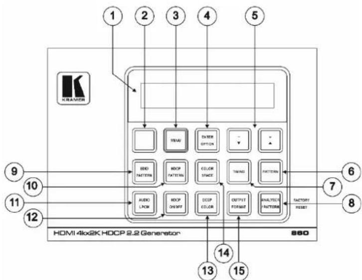
Figure 1: 860 HDMI 18G Signal Generator & Analyzer – Top Panel
| # | Feature | Function |
| 1 | OLED Display | Displays the current signal analysis information or test pattern mode selection details including input and/or output resolution timing. The screen layout changes completely depending on the unit's mode (seeUsing the OLED Displayon page 12). |
| 2 | IR Window | Accepts IR signals from the included IR remote for control of this unit only (seeUsing the Remote Controlon page 13). |
| 3 | MENU Button | Press to enter the OSD menu or to navigate out from menu items (seeUsing the OSD Menuon page 14). |
| 4 | ENTER/OPTION Button | Press to confirm a selection or to go deeper into a menu item. When the selected function has additional options, the associated buttons' LEDs illuminate together with the▼/▲(-/+) buttons. |
| 5 | +/- and▲/▼Buttons | Press to move up and down or adjust selections within menus. These buttons illuminate when the selected function has values that can be adjusted up or down. |
| 6 | PATTERN Button | Pattern mode: Press to enable selection of the test pattern used. The▼/▲buttons illuminate and are used to select the new pattern. The new test pattern automatically becomes active after selecting it and pausing for 2 seconds. Press again to select additional variations (if available).Analyzer mode: Press to turn on/off a "title-safe/action-safe" overlay. |
| 7 | TIMING Button | Press to enable selection of the output timing and resolution used. The▼/▲buttons illuminate and are used to select the new timing. The currently selected timing is shown on the OLED display. The new timing automatically becomes active after selecting it and pausing for 2 seconds.Press and hold for 2 seconds to select "Bypass" timing to disable scaling the source output signal before it is sent to the display. The LED blinks Red when timing is set to Bypass.Press and hold again to exit "Bypass" timing and to return to the previous resolution. |
| 8 | ANALYZER / PATTERN Button | Press to switch the unit between Analyzer Mode (LED=Red) and Pattern Mode (LED=Blue).In Analyzer Mode: Press and hold for 2 seconds to force an RX hot-plug.In Pattern Mode: Press and hold for 2 seconds to turn on/off the AVMute bit within the output's General Control Packet (GCP).Press and hold while powering the unit to perform a factory reset. |
| 9 | EDID PATTERN Button | Press to enable selection of the EDID to use on the HDMI input port. The▼/▲ buttons illuminate and are used to select the new EDID. The currently selected EDID is shown on the OLED display. The new EDID automatically becomes active after selecting it and pausing for 5 seconds. |
| 10 | HDCP PATTERN Button | Press to enable/disable the OSD display of the detected HDCP version support and handshaking information between the sink and source.In Analyzer mode the unit is the RX, in Pattern mode the unit is the TX.In Pattern mode, if HDCP handshaking fails, an error message “HDCP OUT FAIL” is displayed on the OSD. |
| 11 | AUDIO LPCM Button | Analyzer mode: Press to select which digital audio source pair (0-3) is routed to the primary stereo channel (LPCM 2.0 and headphone output) for monitoring. The LED color indicates the selection (Off=SD0, Red=SD1, Blue=SD2, Purple=SD3).Pattern mode: Press to switch between LPCM 2.0 (LED=Red), 5.1 (LED=Blue) and 7.1 (LED=Purple) channel test tone output formats. Press and hold for 2 seconds to allow adjustment of the output volume. |
| 12 | HDCP ON/OFF Button | Press to switch between supported HDCP versions or to disable HDCP. In Analyzer mode: OFF (LED=Off), HDCP 1.4 (LED=Red), and HDCP 1.4+2.2 (LED=Blue) modes are available for the input port. In Pattern mode: OFF, HDCP 1.4, and HDCP 2.2 modes are available for the output port. |
| 13 | DEEP COLOR Button | Press repeatedly to switch between the available output color bit depth options. The button's LED is colored to indicate the current bit depth: Off=8-bit, Red=10-bit, Blue=12-bit. |
| 14 | COLOR Space Button | Press repeatedly to switch between the available color space formats. The button's LED is colored to indicate the current color space: Red=RGB, Blue=YCbCr 4:4:4, Purple=YCbCr 4:2:0, Off=YCbCr 4:2:2. |
| 15 | OUTPUT FORMAT Button | Press to switch between DVI (LED=Blue) and HDMI (LED=Red) output formats. Press and hold the button for 2 seconds to disable/enable video output completely. The button's LED turns off when the output is disabled. |
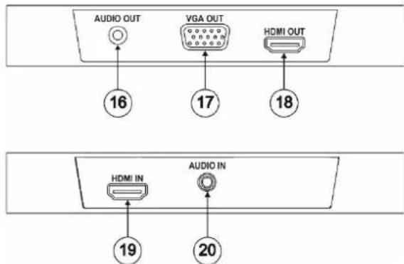
Figure 2: 860 HDMI 18G Signal Generator & Analyzer – Front / Rear Panels
| # | Feature | Function |
| 16 | AUDIO OUT 3.5mm Connector | Connect to powered speakers or an amplifier for stereo analog audio output |
| 17 | VGA OUT Connector | Connect to a VGA (RGBHV) monitor or display for analog video output. |
| 18 | HDMI OUT Connector | Connect to HDMI TVs, monitors or amplifiers for digital video and audio output. |
| 19 | HDMI IN Connector | Connect to HDMI source equipment such as a media player, game console or set-top box. |
| 20 | AUDIO IN 3.5mm Connector | Connect to the stereo analog output of a device such as a CD player or PC. |
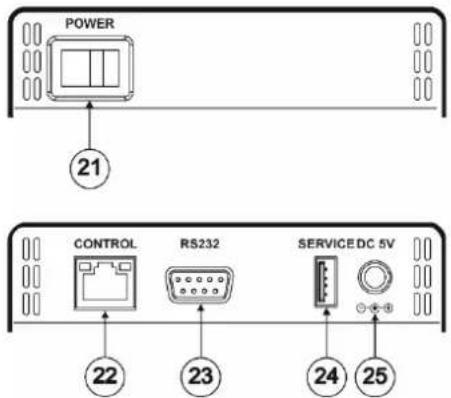
Figure 3: 860 HDMI 18G Signal Generator & Analyzer – Left / Right Panels
| # | Feature | Function |
| 21 | POWER Switch | Powers the device ON or OFF (after connecting a power source). |
| 22 | CONTROL RJ-45 Connector | Connect directly, or through a network switch, to your PC/laptop to control the unit via Telnet. |
| 23 | RS232 Connector | Connect directly to your PC/laptop to send RS-232 commands to control the unit. |
| 24 | SERVICE USB Connector | This slot is used for firmware updates and uploading customer designed test pattern files.Warning: Do not disconnect power to the unit while a firmware update is in progress. |
| 25 | DC 5V | Plug the 5V DC power supply into the unit and connect it to an AC wall outlet. |
Connecting the 860

Always switch off the power to each device before connecting it to your 860. After connecting your 860, connect its power and then switch on the power to each device.

You do not have to connect all the inputs and outputs, connect only those that are required.
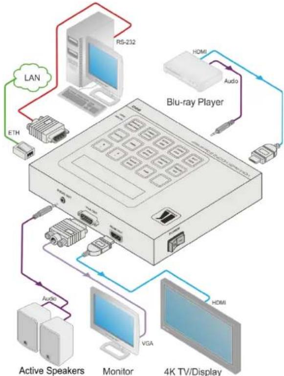
To connect the 860, as illustrated in the example in Figure 4, do the following:
- Connect a source device to the HDMI IN connector (for example, a Blu-ray player).
- If required, connect an analog audio source device to the AUDIO IN 3.5mm connector (for example, a Blu-ray player).
- Connect the HDMI OUT connector to an HDMI acceptor (for example, a 4K TV).
- Connect the VGA OUT connector to a VGA monitor.
- If required, connect the AUDIO OUT connector to an analog audio acceptor (for example, powered speakers).
- Connect a PC to the RS-232 connector.
- Connect the CONTROL RJ-45 connector to your local area network.
- Connect the power cord (not shown in Figure 4).
flowchart
graph TD
    A["Blu-ray Player"] -->|LAN| B["RS-232"]
    A -->|Audio| C["Monitor"]
    A -->|HDMI| D["4K TV/Display"]
    A -->|VGA| E["Active Speakers"]
    A -->|Audi| F["Hardware"]
    A -->|ETH| G["Computer"]
    A -->|HDMI Audio| H["Hardware"]
Figure 4: Connecting the 860 HDMI 18G Signal Generator & Analyzer
Connecting to the 860 via RS-232
You can connect to the 860 via an RS-232 connection using, for example, a PC. Note that a null-modem adapter/connection is not required.
To connect to the 860 via RS-232, connect the RS-232 9-pin D-sub rear panel port on the 860 via a 9-wire straight cable (only connect pin 2 to pin 2, pin 3 to pin 3, and pin 5 to pin 5) to the RS-232 9-pin D-sub port on your PC
Connecting to the 860 via Ethernet
You can connect to the 860 via Ethernet using either of the following methods:
- Directly to the PC using a crossover cable (see Connecting the Ethernet Port Directly to a PC on page 9)
- Via a network hub, switch, or router, using a straight-through cable (see Connecting the Ethernet Port via a Network Hub on page 11)

If you want to connect via a router and your IT system is based on IPv6, contact your IT department for specific installation instructions.
Connecting the Ethernet Port Directly to a PC
You can connect the Ethernet port of the 860 directly to the Ethernet port on your PC using a crossover cable with RJ-45 connectors.

This type of connection is recommended for identifying the 860 with the factory configured default IP address.
After connecting the 860 to the Ethernet port, configure your PC as follows:
- Click Start > Control Panel > Network and Sharing Center.
- Click Change Adapter Settings.
- Highlight the network adapter you want to use to connect to the device and click Change settings of this connection.
The Local Area Connection Properties window for the selected network adapter appears as shown in Figure 5.
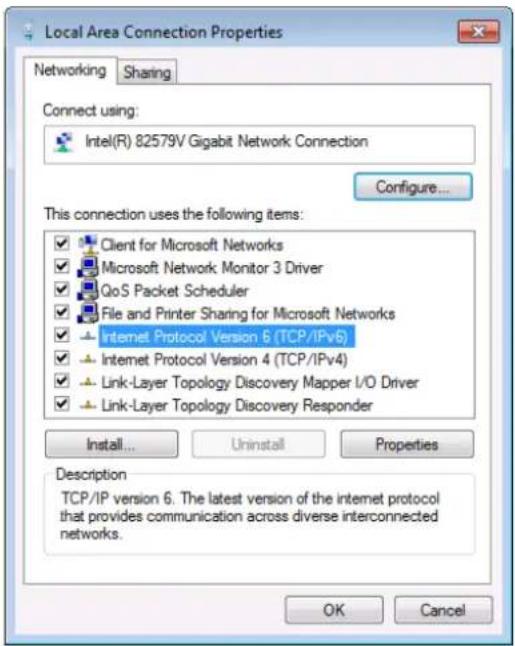
Figure 5: Local Area Connection Properties Window
- Highlight either Internet Protocol Version 6 (TCP/IPv6) or Internet Protocol Version 4 (TCP/IPv4) depending on the requirements of your IT system.
- Click Properties.
The Internet Protocol Properties window relevant to your IT system appears as shown in Figure 6 or Figure 7.
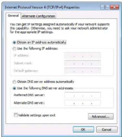
Figure 6: Internet Protocol Version 4 Properties Window
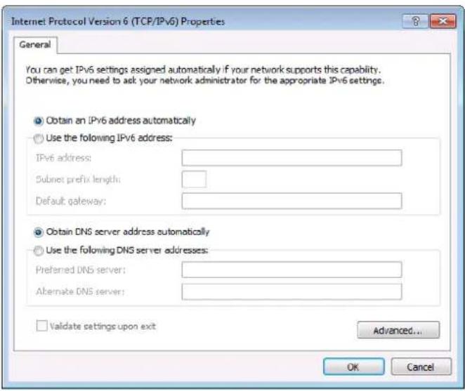
Figure 7: Internet Protocol Version 6 Properties Window
- Select Use the following IP Address for static IP addressing and enter the details as shown in Figure 8.
For TCP/IPv4 you can use any IP address between 192.168.1.1 to 192.168.1.255 (excluding 192.168.1.39) that is provided by your IT department.
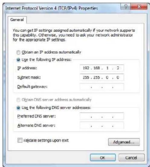
Figure 8: Internet Protocol Properties Window
- Click OK.
- Click Close.
Connecting the Ethernet Port via a Network Hub or Switch
You can connect the Ethernet port of the 860 to the Ethernet port on a network hub or using a straight-through cable with RJ-45 connectors.
Configuring the Ethernet Port
You can set the Ethernet parameters via the OSD menu (see Using the OSD Menu on page 14).
Operating the 860
Using the OLED Display
In Analyzer mode (Analyzer / Pattern button is red), if there is no live video source detected on the input port, the OLED displays any voltage, TMDS, or sync that may be present (Figure 9). Once a live video signal is detected, the unit displays that signal's current timing, format, HDCP version, AV Mute status, color space, color depth, and audio format (Figure 10).
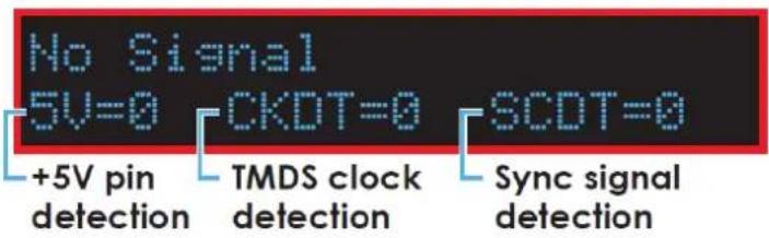
Figure 9: OLED Display – Analyzer Mode without Live Video Signal
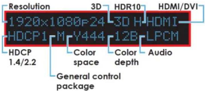
Figure 10: OLED Display – Analyzer Mode with Live Video Signal
In Pattern mode (Analyzer / Pattern button is blue), when the output is not connected to a sink, the unit displays the current output timing, RX Sense, and Hot-plug detection (HPD) status (Figure 11). Once an active sink is connected, the lower portion of the display changes to indicate the current test pattern number and name. If the output timing is auto/native an “A “appears on the upper portion of the display, next to the output timing (Figure 12).
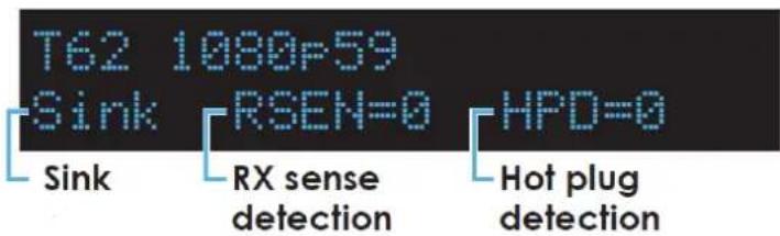
Figure 11: OLED Display – Pattern Mode without Connected Sink
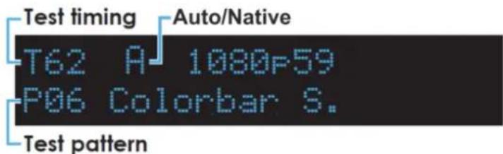
Figure 12: OLED Display – Pattern Mode with Connected Sink
Using the Remote Control
The IR remote uses one out of 4 available address channels for control of the test pattern generator, allowing up to 4 to be located in the same area while being controlled by different remotes.
To connect a serial controller to the 860:
- In the OSD main menu, select Setup > IR Controller Address.
- Assign an address number (from 0 to 3) that matches the setting on the remote used with the unit (Figure 13). The default factory setting is 0.
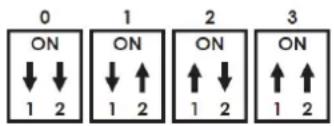
Figure 13: IR Remote Address Number
The IR remote's address can be set using the two DIP switches located on the back of the remote, inside the battery cover. The default factory setting is 0 (off, off).
You can control the 860 using the infrared remote control transmitter:
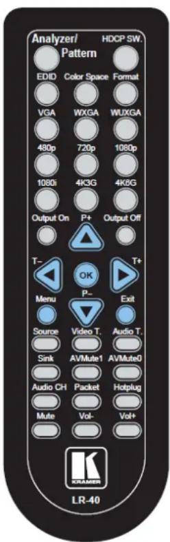
Figure 14: Infrared Remote Control Transmitter
| Keys | Function |
| Analyzer / Pattern | Switch between Analyzer and Pattern mode. |
| EDID | Switch between the available EDIDs for the HDMI input. |
| Color Space | Switch between the available color space formats (RGB, YCbCr 4:4:4, YCbCr 4:2:2 and YCbCr 4:2:0). |
| HDCP SW | Switch between supported HDCP versions or to disable HDCP. |
| Format | Switch between DVI and HDMI output formats. |
| VGA / WXGA / WUXGA / 480p / 720p / 1080p / 1080i / 4K3G / 4K6G | Directly select the output resolution. |
| Output On / Output Off | Enable / disable video output. |
| T- / T+ | Select a new output resolution timing. In the OSD menu, adjust selections. |
| P+ / P- | Change the current test pattern. In the OSD menu, move up and down. |
| OK | After selecting a pattern, press and hold for 2 seconds to switch to alternate variations of the pattern. In the OSD menu, press to confirm selections. |
| Menu | Enter the OSD menu. |
| Exit | Exit the OSD or cancel the selection. |
| Source | Display source signal information on the OSD (Analyzer mode only). |
| Video T / Audio T | Display video / audio analysis details on the OSD (Analyzer mode only). |
| Packet Display the HDMI input's packet analysis information (Analyzer mode only). | |
| Hotplug | Force an RX hot-plug event on the input port (Analyzer mode only). |
| Sink | Display HDMI output detection / information on the OSD (Pattern mode only). |
| AVMute 1 / AVMute 0 | Turn on / off the AVMute bit in the output's GCP (Pattern mode only). |
| Audio CH Analyzer mode: Select which digital audio source pair (0–3) is routed to the primary stereo channel for monitoring. Pattern mode: Switch between LPCM 2.0, 5.1 and 7.1 channel test tone output formats. | |
| Mute / Vol- / Vol+ | Press Mute to mute both digital and analog audio outputs. Press Vol- / Vol+ to increase / decrease volume. |
Using the OSD Menu
The control buttons let you control the 860 via the OSD menu. Press the:
- MENU button to enter or exit a menu
- ENTER button to accept changes and to change menu settings
- Arrow buttons to navigate the OSD menu, which is displayed on the video output
The OSD menu differs according to the selected mode:
• Analyzer mode (see Analyzer Mode on page 15).
- Pattern mode (see Pattern Mode on page 22).
Analyzer Mode
| Main Menu | Sub Menu | Adjustments | Default |
| Source Monitor | Analytic Data | ||
| Video Timing | Analytic Data | ||
| Audio Timing | Analytic Data | ||
| Packet | Analytic Data | ||
| EDID Analyzer | HDMI Sink | Analytic Data | |
| VGA Sink | Analytic Data | ||
| RX EDID | Analytic Data | ||
| Default & Copied EDID | [D1]~[D10] Default EDID Settings & [C1]~[C10] Copied EDID Settings | ||
| EDID Emulator | RX EDID Select | Copy HDMI Sink | [D4] 8B 2D 2CH LPCM HD |
| [D1] DVI | |||
| [D2] VGA | |||
| [D3] 8B 2D 2CH LPCM PC | |||
| [D4] 8B 2D 2CH LPCM HD | |||
| [D5] 12B 2D 8CH Bits 720p | |||
| [D6] 12B 3D 8CH Bits HD | |||
| [D7] 12B 2D 8CH Bits 4K6G | |||
| [D8] 12B 2D 8CH HBR 4K3G | |||
| [D9] 12B 2D 8CH HBR 4K420 | |||
| [D10] 12B 2D 8CH HBR 4K6G | |||
| [C1] Copy 01 | |||
| [C2] Copy 02 | |||
| [C3] Copy 03 | |||
| [C4] Copy 04 | |||
| [C5] Copy 05 | |||
| [C6] Copy 06 | |||
| [C7] Copy 07 | |||
| [C8] Copy 08 | |||
| [C9] Copy 09 | |||
| [C10] Copy 10 | |||
| Copy HDMI Sink EDID | [C1]~[C10] Copied EDID Settings | ||
| Copy VGA Sink EDID | [C1]~[C10] Copied EDID Settings | ||
| Rename Copied Sink EDID | [C1]~[C10] Copied EDID Settings | ||
| Burn EDID to HDMI Sink | [D1]~[D10] Default EDID Settings & [C1]~[C10] Copied EDID Settings | ||
| Burn EDID to VGA Sink | [D1]~[D10] Default EDID Settings & [C1]~[C10] Copied EDID Settings | ||
| HDCP Input Monitor | Analytic Data | ||
| SCDC Input Monitor | Analytic Data | ||
| RX Port Controls | Hot Plug Preset | Low | Toggle |
| High | |||
| Toggle | |||
| Hot Plug Toggle Time | 50ms~500ms | 150ms | |
| Hot Plug Run | |||
| RX Sense | On | On (PoR) | |
| Off | |||
| DDC | On | On (PoR) | |
| Off | |||
| V.Freq/1.001 Detection | On | On | |
| Off | |||
| HDCP Port On/ Off | On | On (PoR) | |
| Off | |||
| HDCP Port Version | v1.4 | v1.4+v2.2 | |
| v1.4+v2.2 | |||
| HDCP REAUTH_REQ Toggle | |||
| HDCP Counter Reset | |||
| SCDC Port | On | On | |
| Off | |||
| SCDC CED Ch Auto Clear | On (Auto clear while source reads the Character Error Detection (CED)) | Off | |
| Off | |||
| Output Resolution | T01 640x350p85~T88 Bypass | 1080p60 | |
| OSD Settings | H Position | 0%~100% | 10% |
| V Position | 0%~100% | 10% | |
| Transparency | 0~7 (Solid~Transparent) | 4 | |
| A Mode Color (Analyzer Mode) | Red | Red | |
| Blue | |||
| Gray | |||
| P Mode Color (Pattern Mode) | Red | Blue | |
| Blue | |||
| Gray | |||
| Ethernet | IP Mode | DHCP | Static |
| Static | |||
| IP Address | a.b.c.d (Static Mode) | 192.168.1.39 | |
| Subnet Mask | a.b.c.d (Static Mode) | 255.255.0.0 | |
| Gateway | a.b.c.d (Static Mode) | 0.0.0.0 | |
| Setup | Firmware Update | No | No |
| Yes | |||
| Image 640x480 Update | No | No | |
| Yes | |||
| Image 1920x1080 Update | No | No | |
| Yes | |||
| [Letter H] Option 2 | Small | Medium | |
| Medium | |||
| 3D Source Image Bypass | No | No | |
| Yes | |||
| Information Refresh | 1 Sec | 2 Sec | |
| 2 Sec | |||
| Manual | |||
| IR Controller Address (see Using the Remote Control on page 13) | 0~3 | 0 | |
| Copied EDID Reset | No | No | |
| Yes | |||
| Ethernet Reset | No | No | |
| Yes | |||
| Factory Reset | No | No | |
| Yes | |||
| Information | Analytic Data |

The Power on Reset (PoR) setting is reset when the unit is powered off.
Image file format: 640×480 / 1920×1080 (RGB, 24-bit, bitmap).
Do not disconnect power to the unit while a firmware update is in progress.

Understanding Analyzer Mode Information
This section provides additional information on the Analyzer mode OSD menus.
Source Monitor
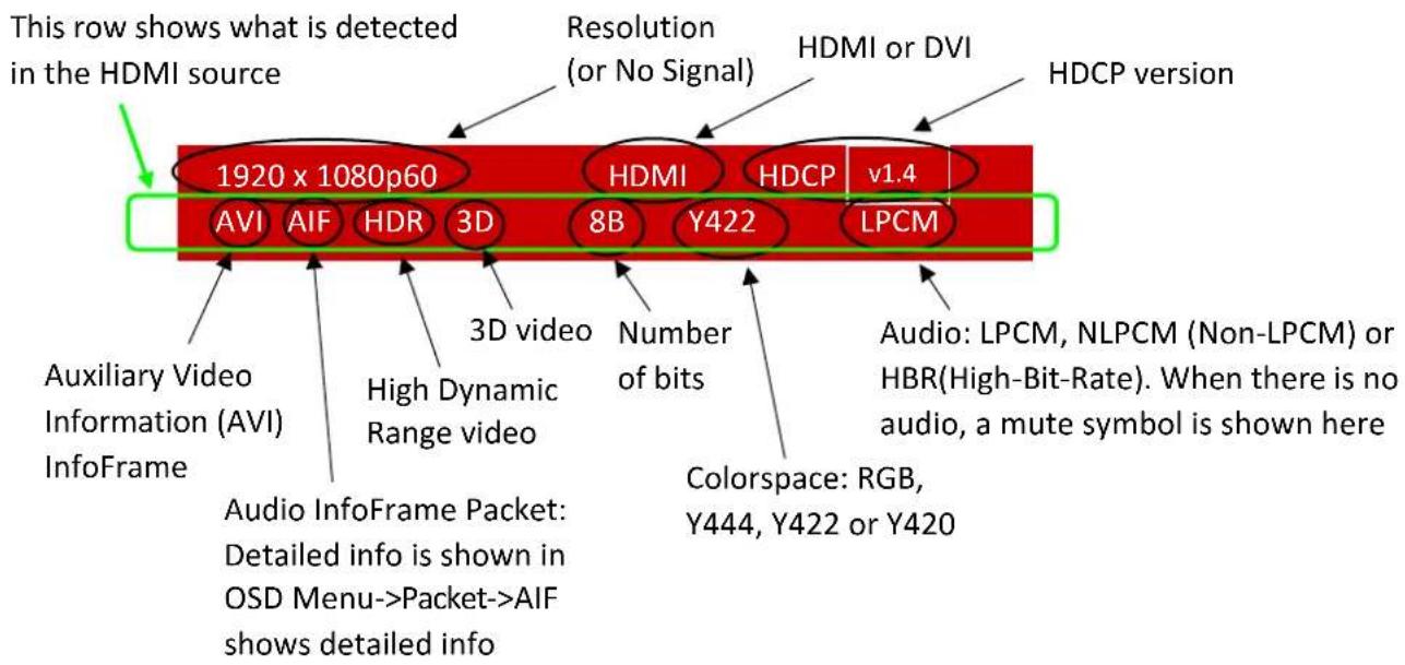
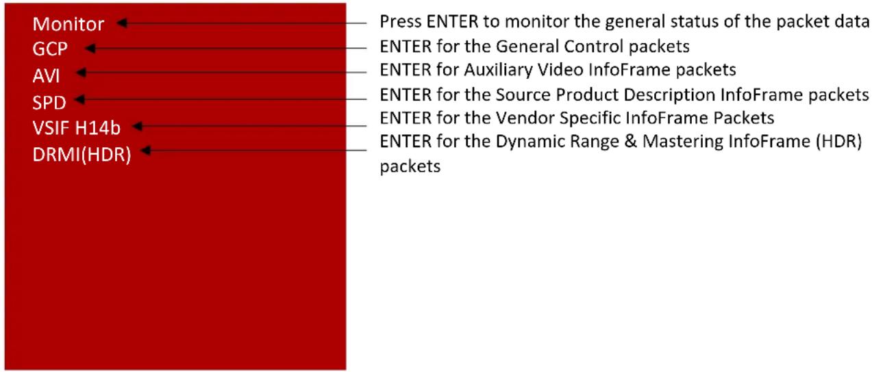
The following parameters may also be displayed:
- 5V (ON or OFF) – Shows whether or not 5V is detected on pin 18.
- CKDT (ON or OFF) – Shows whether or not the source clock is detected.
- SCDT (ON or OFF) – Shows whether or not the source sync is detected.
Video Timing
| Timing | >1920x1080p60 | Input resolution detected |
| TMDS Clock | >185638kHz 10bits | Number of bits per pixel |
| Pixel Clock | >148510kHz | TMDS clock rate |
| Data Rate | >5.569Gbps | Pixel clock rate |
| H Frequency | >67504Hz | Data rate |
| H Total | >2200 pixel | Horizontal frequency |
| H Active | >1920 pixel | Total number of horizontal pixels (active pixels + blanking) |
| H Back Porch | >148 pixel | Number of active horizontal pixels |
| H Sync Width | >44 pixel | Width of horizontal back porch (measured in pixels) |
| H Front Porch | >88 pixel | Width of horizontal sync (measured in pixels) |
| H Sync Polarity | >Positive | Width of horizontal front porch (measured in pixels) |
| V Frequency | >60.00Hz | Horizontal sync polarity (positive or negative) |
| V Total | >1125 line | Vertical frequency |
| V Active | >1080 line | Total number of vertical lines (active lines + blanking) |
| V Back Porch | >36 line | Number of active vertical lines |
| V Sync Width | >5 line | Number of lines in the vertical back porch |
| V Front Porch | >4 line | Number of lines in the vertical sync |
| V Sync Polarity | >Positive | Number of lines in the vertical back porch |
| HV Sync Offset1 | >0 dot | Vertical sync polarity (positive or negative) |
| HV Sync Offset2 | >0 dot | Progressive source: Start position offset of “Hori. Sync to Vert. Sync” |
| Scan Mode | >Progressive | Interlaced source: Start position of even field “Hori. Sync to Vert. Sync” |
| Start position of odd field “Hori. Sync to Vert. Sync” (only valid for interlaced source) | ||
| Progressive or interlaced scanning |
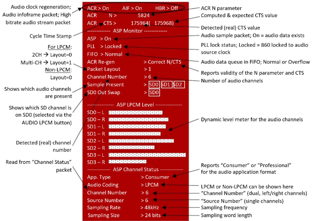
Audio Timing
Packet
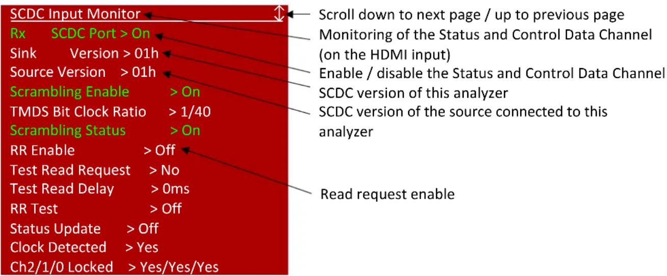
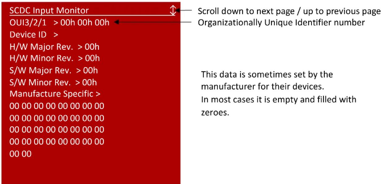
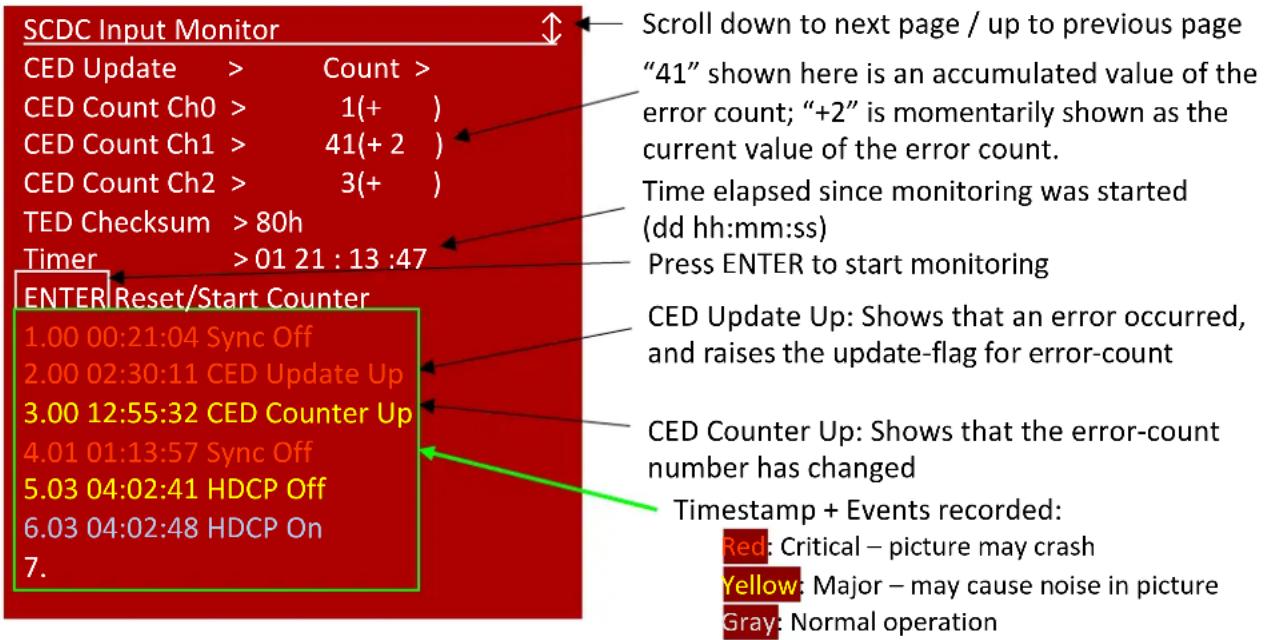
SCDC Input Monitor
For information about the Status and Control Data Channel, refer to chapter 10 of the HDMI 2.0b Specification.
![SCDC Input Monitor [Rx EDID] HDMI Forum VSDB > 0xC45DD8 Version > 01h Max TMDS Char.Rate > 600MHz LTE 340Mcsc Scramble > No SCDC RR Capable > No SCDC Present > Yes Scroll down to next page / up to previous page Vendor Specific Data Block Less than or equal to 340 Mcsc scrambling support Analysis of 860's Rx EDID: Data is shown for 860 Rx EDID set for 6G EDID](/content/2026/05/1015477/images/64cac32e32bf493e8dd1c235dc05b9be760a0574b073693411864df6f3c32ca7.jpg)
Pattern Mode
| Main Menu | Sub Menu | Adjustments | Default |
| Sink Monitor | Analytic Data | ||
| Pattern | P01 Border ~ P55 Window Yellow | ||
| Audio Output | Source | HDMI In | Int. Sinewave (PoR) |
| Analog In | |||
| Int. Sinewave | |||
| Volume | 0~80 | 70 | |
| Analog Out CH | SD0 L/R | SD0 L/R | |
| SD1 L/R | |||
| SD2 L/R | |||
| SD3 L/R | |||
| Sampling Rate | 48kHz | 48kHz | |
| 96kHz | |||
| 192kHz | |||
| Word Length | 16 Bits | 24 Bits | |
| 20 Bits | |||
| 24 Bits | |||
| Channels | 2CH | 7.1CH | |
| 5.1CH | |||
| 7.1CH | |||
| SD0-L Freq. | Mute | 1000Hz | |
| 200Hz~1600Hz | |||
| SD0-R Freq. | Mute | ||
| 200Hz~1600Hz | |||
| SD1-L Freq. | Mute | ||
| 200Hz~1600Hz | |||
| SD1-R Freq. | Mute | ||
| 200Hz~1600Hz | |||
| SD2-L Freq. | Mute | ||
| 200Hz~1600Hz | |||
| SD2-R Freq. | Mute | ||
| 200Hz~1600Hz | |||
| SD3-L Freq. | Mute | ||
| 200Hz~1600Hz | |||
| SD3-R Freq. | Mute | ||
| 200Hz~1600Hz | |||
| EDID Analyzer | Analytic Data | ||
| EDID Emulator | |||
| HDCP Output Monitor | |||
| HDR Output Emulator | HDR Out On/Off | On | Off |
| Off | |||
| Settings | 1 | 1 | |
| 2 | |||
| 3 | |||
| Value Unit | Hex | nit(cd/m*m) | |
| nit(cd/m*m) | |||
| Tx AVI Colorimetry | No Data | BT.2020(2) | |
| ITU601 | |||
| ITU709 | |||
| xvYCC601 | |||
| xvYCC709 | |||
| sYCC601 | |||
| AdobeY601 | |||
| Adobe RGB | |||
| BT.2020(1) | |||
| BT.2020(2) | |||
| EOTF | 0:SDR Luminance Range | 0:SDR Luminance Range | |
| 1:HDR Luminance Range | |||
| 2:SMPTE ST 2084[2] | |||
| 3:Future EOTF | |||
| Metadata Descriptor | Static Metadata Type 1 | Static Metadata Type 1 | |
| Reserved | |||
| display primaries x0 | 0.0000 ~ 1.3100 | 0.0000 | |
| display primaries y0 | 0.0000 ~ 1.3100 | ||
| display primaries x1 | 0.0000 ~ 1.3100 | ||
| display primaries y1 | 0.0000 ~ 1.3100 | ||
| display primaries x2 | 0.0000 ~ 1.3100 | ||
| display primaries y2 | 0.0000 ~ 1.3100 | ||
| white point x | 0.0000 ~ 1.3100 | ||
| white point y | 0.0000 ~ 1.3100 | ||
| max disp mastering lumi | 0 ~ 65500 | 0 | |
| min disp mastering lumi | 0.0000 ~ 6.5500 0.0000 | ||
| Max Content Light Level | 0 ~ 65500 | 0 | |
| Max Frame-average L-L | 0 ~ 65500 | ||
| Tx AVI Color Space | |||
| Sink EDID supports HDR | |||
| SCDC Output Monitor | Analytic Data | ||
| TX Port Controls | +5V Out On/Off | Follow TMDS | Follow TMDS |
| Always on | |||
| HDCP Output On/Off | On | Off (PoR) | |
| Off | |||
| HDCP Output Version | v1.4 | v1.4 | |
| v2.2 | |||
| HDCP AKE_Send_Stored_km() | On | Off | |
| Off | |||
| HDCP Counter Reset | |||
| SCDC CED Counter Read | On | On | |
| Off (TX doesn't read sink CH0~3 Error-Counter) | |||
| SCDC CED Always Read | On (TX ignores sink CED_Update flag) | On | |
| Off | |||
| SCDC CED Ch Auto Clear | On (While sink CED_Update flag=1, TX auto clear itself CH0~3 Error- Counter. And read new counter from sink) | Off | |
| Off | |||
| Output Resolution | T01 640x350p85~T88 Bypass (T88 is available in Analyzer mode) | 1080p60 | |
| OSD Settings | H Position | 0%~100% | 10% |
| V Position | 0%~100% | 10% | |
| Transparency | 0~7 (Solid ~ Transparent) | 4 | |
| A Mode Color (Analyzer Mode) | Red | Red | |
| Blue | |||
| Gray | |||
| P Mode Color (Pattern Mode) | Red | Blue | |
| Blue | |||
| Gray | |||
| Ethernet | IP Mode | DHCP | Static |
| Static | |||
| IP Address | a.b.c.d (Static Mode) | 192.168.1.39 | |
| Subnet Mask | a.b.c.d (Static Mode) | 255.255.0.0 | |
| Gateway | a.b.c.d (Static Mode) | 0.0.0.0 | |
| Setup | Firmware Update | No | No |
| Yes (860_v2.07K.bin) | |||
| Image 640x480 Update | No | No | |
| Yes (IMG_480.BMP) | |||
| Image 1920x1080 Update | No | No | |
| Yes (IMG_1080.BMP) | |||
| [Letter H] Option 2 | Small | Medium | |
| Medium | |||
| 3D Source Image Bypass | No | No | |
| Yes | |||
| Information Refresh | 1 Sec | 2 Sec | |
| 2 Sec | |||
| Manual | |||
| IR Controller Address | 0~3 | 0 | |
| Copied EDID Reset | No | No | |
| Yes | |||
| Ethernet Reset | No | No | |
| Yes | |||
| Factory Reset | No | No | |
| Yes | |||
| Information | Analytic Data |


The Power on Reset (PoR) setting is reset when the unit is powered off.
Do not disconnect power to the unit while a firmware update is in progress.
Test Timings and Patterns
The 860 supports a total of 87 resolutions.

The VGA output only supports RGBHV (No YUV, RGBS or RGsB support). The OSD menu display is not supported over the VGA output.
In Analyzer mode, the VGA output is turned off.
Input Timings
| Resolutions | Vertical Frequency (Hz) | HDMI |
| 640×350p | 85 | √ |
| 640×480p | 59, 72, 75, 85 | √ |
| 720×400p | 70, 85 | √ |
| 800×600p | 56, 60, 72, 75, 85 | √ |
| 848×480p | 60 | √ |
| 1024×768p | 60, 70, 75, 85 | √ |
| 1152×864p | 70, 75, 85 | √ |
| 1280×768p | 60 (RB), 60, 75, 85 | √ |
| 1280×800p | 60 (RB), 60, 75, 85 | √ |
| 1280×960p | 60, 85 | √ |
| 1280×1024p | 60, 75, 85 | √ |
| 1360×768p | 60 | √ |
| 1366×768p | 60 (RB), 60 | √ |
| 1400×1050p | 60 (RB), 60 | √ |
| 1440×900p | 60 (RB), 60 | √ |
| 1600×900p | 60 (RB) | √ |
| 1600×1200p | 60 | √ |
| 1680×1050p | 60 (RB), 60 | √ |
| 1920×1200p | 60 (RB) | √ |
| 480i | 59, 60 | √ |
| 480p | 59, 60 | √ |
| 576i | 50 | √ |
| 576p | 50 | √ |
| 720p | 25, 29, 30, 50, 59, 60 | √ |
| 1080i | 50, 59, 60 | √ |
| 1080p | 23, 24, 25, 29, 30, 50, 59, 60 | √ |
| 2048×1080p | 23, 24, 25, 29, 30, 50, 59, 60 | √ |
| 3840×2160p | 23, 24, 25, 29, 30, 50, 59, 60 | √ |
| 4096×2160p | 23, 24, 25, 29, 30, 50, 59, 60 | √ |
Output Timings
| Resolutions | Vertical Frequency (Hz) | HDMI | DVI | VGA |
| 640×350p | 85 | √ | √ | √ |
| 640×480p | 59, 72, 75, 85 | √ | √ | √ |
| 720×400p | 70, 85 | √ | √ | √ |
| 800×600p | 56, 60, 72, 75, 85 | √ | √ | √ |
| 848×480p | 60 | √ | √ | √ |
| 1024×768p | 60, 70, 75, 85 | √ | √ | √ |
| 1152×864p | 75 | √ | √ | √ |
| 1280×768p | 60 (RB), 60, 75, 85 | √ | √ | √ |
| 1280×800p | 60 (RB), 60, 75, 85 | √ | √ | √ |
| 1280×960p | 60, 85 | √ | √ | √ |
| 1280×1024p | 60, 75, 85 | √ | √ | √ |
| 1360×768p | 60 | √ | √ | √ |
| 1366×768p | 60 (RB), 60 | √ | √ | √ |
| 1400×1050p | 60 (RB), 60 | √ | √ | √ |
| 1440×900p | 60 (RB), 60 | √ | √ | √ |
| 1600×900p | 60 (RB) | √ | √ | √ |
| 1600×1200p | 60 | √ | √ | √ |
| 1680×1050p | 60 (RB), 60 | √ | √ | √ |
| 1920×1200p | 60 (RB) | √ | √ | √ |
| 480i | 59, 60 | √ | √ | |
| 480p | 59, 60 | √ | √ | √ |
| 576i | 50 | √ | √ | √ |
| 576p | 50 | √ | √ | √ |
| 720p | 50, 59, 60 | √ | √ | √ |
| 1080i | 50, 59, 60 | √ | √ | |
| 1080p | 23, 24, 25, 29, 30 | √ | √ | |
| 50, 59, 60 | √ | √ | √ | |
| 2048×1080p | 23, 24, 25, 29, 30, 50, 59, 60 | √ | √ | |
| 3840×2160p | 23, 24, 25, 29, 30, 50, 59, 60 | √ | ||
| 4096×2160p | 23, 24, 25, 29, 30, 50, 59, 60 | √ |
Test Patterns
1. Border
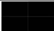
The Border pattern presents 4 equal-sized squares dividing the screen into 4 quadrants, forming a central white cross, with red, green, blue and white inner squares. Ideal for testing screen boundary, alignment and pincushion issues. All lines should be straight, and edge transitions should be sharp.
2. Checkerboard
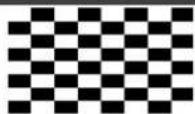
8×8
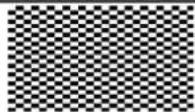
24x24
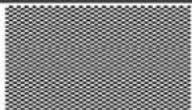
48×48
The Checkerboard pattern displays a repeating black and white checkerboard image. This is ideal for checking the alignment and corner convergence of TVs or monitors. Bandwidth can be checked by observing the vertical transitions. Transitions from black to white should be sharp. There are 3 variations: 8x8, 24x24 and 48x48.
3.Circle 1
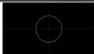
The Circle 1 pattern provides a single white circle in the middle with a white cross and a white outer border line. This pattern is designed for quickly confirming that the geometry of the scene is correct and that the full source is being displayed, edge to edge.
4. Circle 4
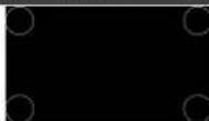
The Circle 4 pattern provides 4 smaller white circles in each of the 4 corners of the screen. This pattern can help confirm that the display is maintaining correct geometry at the edges of the screen.
5. Black
- Blue
- Cyan
- Green
9. Magenta
- Red
- White
- Yellow
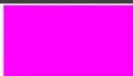
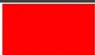
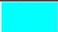
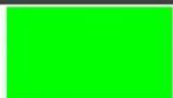
These patterns are full screen purity tests offering eight different full field patterns: Black, Blue, Cyan, Green, Magenta, Red, White, Yellow. The color patterns should display an even distribution of brightness and consistent color tone across the screen. The 100% white pattern should display evenly across the screen and not cause the display's overall brightness to lower, or for the image to become instable. The black pattern will give a good idea of the display's true minimum brightness capability and is helpful for setting the viewing room lighting levels.
13. Colorbar Delay
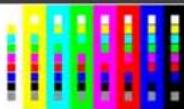
The Colorbar Delay pattern provides a sequence of standard 100% color bars with a full set of smaller color squares within each bar. This test is primarily to detect if any of the color components of the video signal are delayed/skewed relative to each other. Pay close attention to the left and right sides of the squares and look for a color shift. This is a common problem when using extreme-length analog extension products, or very long analog cables.
14. Colorbar-H
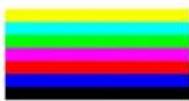
The Colorbar-H pattern is a standard (white, yellow, cyan, green, magenta, red, blue, black) 100% color bar pattern using horizontal bars.
15. Colorbar Motion
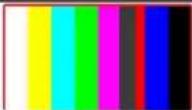
The Colorbar Motion pattern is a standard (white, yellow, cyan, green, magenta, red, blue, black) 100% color bar pattern using vertical bars with a grey bar moving horizontally across it. There are 2 variations: slow and fast motion of the grey bar.
16. Colorbar S.
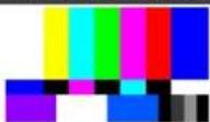
The Colorbar S. pattern is a standard SMPTE color bar pattern which is used for rapid verification of signal color accuracy and for display setup using the Blue-Only option on your display, if it has one.
17. Colorbar Split
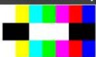
The Colorbar Split pattern is a vertical color bar pattern with the color bars split in the middle by large black and white sections. All colors (white, yellow, cyan, green, magenta, red, blue) are at 100% brightness.
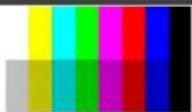
18. Colorbar-V (3 variations)
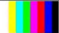
100%
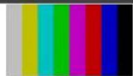
75%
100% & 75%
The Colorbar-V pattern comes in 3 variations. The first is a standard (white, yellow, cyan, green, magenta, red, blue, black) 100% color bar pattern using vertical bars. The 2nd variation has all bars at 75% brightness. The 3rd variation is split with the top half being at 100% and the lower half being at 75% brightness.
19. Cross Hatch 8 (2 variations)
Normal
Inverse
The Cross Hatch 8 pattern is a full field black & white pattern of crossing vertical and horizontal lines dividing the screen into 8 sections in each direction. This pattern is primarily used to check for color convergence and pincushion issues in projectors. There are 2 variations: Normal (white lines, black field) and Inverse (black lines, white field).
20. Cross Hatch 16 (2 variations)
Normal
Inverse
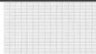
The Cross Hatch 16 pattern is a full field black & white pattern of crossing vertical and horizontal lines dividing the screen into 16 sections in each direction. This pattern is primarily used to check for color convergence and pincushion issues in projectors. There are 2 variations: Normal (white lines, black field) and Inverse (black lines, white field).
21. Cross Hatch 32 (2 variations)
Normal
Inverse
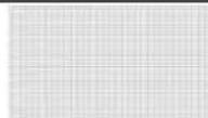
The Cross Hatch 32 pattern is a full field black & white pattern of crossing vertical and horizontal lines dividing the screen into 32 sections in each direction. This pattern is primarily used to check for color convergence and pincushion issues in projectors. There are 2 variations: Normal (white lines, black field) and Inverse (black lines, white field).
22. Diagonal 1
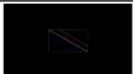
The Diagonal 1 pattern is a set of 3 diagonal colored lines (red, white and blue) within a white square in the middle of the screen. This pattern is used to check for distortion and alignment issues in the center of the screen.
23. Diagonal 2
The Diagonal 2 pattern is 2 diagonal lines that travel from the corners to the exact center of the display. This can be used to check for alignment and geometry issues, particularly with projectors. The outer border of the screen also has a white outline to verify that the full image is being displayed.
24. Dot
The Dot pattern is a full field black & white pattern with a repeating pattern of single-pixel (resolutions below 4K) or 4-pixel (at 4K) white dots surrounded by single pixels of black. This pattern is ideal for testing the signal path/display for bandwidth issues, interference, cross-talk or scaling issues.
25. General (3 variations)
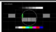
Stop/Slow/Fast Motion
The General pattern is an all-purpose, multi-pattern test to visually check for multiple issues simultaneously. It includes color bars, 8-step greyscale, vertical and horizontal multi-burst, cross hatch, circle and motion patterns. There are 3 variations: No motion, slow motion and fast motion.
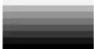
26. Grayscale 8 (3 variations)
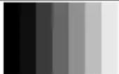
Vert. Bar

Vert. L/R Bar
Hori. Bar
The Grayscale 8 pattern provides a way to check and adjust the contrast, brightness and grayscale tracking of your display with 8 bars progressing from 0% to 100% brightness in even steps. When testing a display, no color should be visible in any of the bars, and all bars should be visible and distinct. There are 3 variations: 8 vertical bars, two sets of 8 vertical bars with the lower set reversed, and 8 horizontal bars.
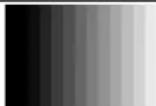
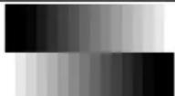
27. Grayscale 16 (3 variations)
Vert. Bar
Vert. L/R Bar

Hori. Bar
The Grayscale 16 pattern provides a way to check and adjust the contrast, brightness and grayscale tracking of your display with 16 bars progressing from 0% to 100% brightness in even steps. When testing a display, no color should be visible in any of the bars, and all bars should be visible and distinct. There are 3 variations: 16 vertical bars, two sets of 16 vertical bars with the lower set reversed, and 16 horizontal bars.
28. Grayscale 32 (3 variations)

Vert. Bar

Vert. L/R Bar

Hori. Bar
The Grayscale 32 pattern provides a way to check and adjust the contrast, brightness and grayscale tracking of your display with 32 bars progressing from 0% to 100% brightness in even steps. When testing a display, no color should be visible in any of the bars, and all bars should be visible and distinct. There are 3 variations: 32 vertical bars, two sets of 32 vertical bars with the lower set reversed, and 32 horizontal bars.
29. Grayscale 64 (3 variations)

Vert. Bar

Vert. L/R Bar

Hori. Bar
The Grayscale 64 pattern provides a way to check and adjust the contrast, brightness and grayscale tracking of your display with 64 bars progressing from 0% to 100% brightness in even steps. When testing a display, no color should be visible in any of the bars, and all bars should be visible and distinct. There are 3 variations: 64 vertical bars, two sets of 64 vertical bars with the lower set reversed, and 64 horizontal bars.
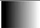
30. Grayscale 256 (4 variations)
Gray
Red
Green
Blue
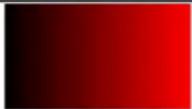
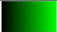
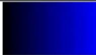
The Grayscale 256 pattern provides a way to fine tune the contrast, brightness and grayscale tracking of your display with a full 265 step gradient progressing from 0% to 100% brightness. When testing a display, no color should be visible at any point across the gradient, and the transition from black to white should appear even and consistent. There are 3 variations: 256 vertical bars, two sets of 256 vertical bars with the lower set reversed, and 265 horizontal bars.
31. Grayscale 256RGB
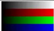
The Grayscale 256RGB pattern provides a way to fine tune the contrast, brightness, grayscale and color tracking of your display with a four full 265 step gradients (gray, red, green, blue) progressing from 0% to 100% brightness. When testing a display, the transition from dark to light should appear even and consistent across all 4 sections.
32. Grayscale Adjust (254 variations)
Adjustable - 1–254
The Grayscale Adjust pattern provides a full field of grey with user adjustable brightness levels for testing display gray purity and signal response. The brightness can be freely adjusted from 1 to 254 by pressing the PATTERN button followed by the -/+ buttons. The gray level number will appear in text on screen while it is in adjusting mode.
33. Grayscale H
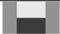
The Grayscale H pattern provides 4 distinct gray fields in an “H” arrangement for testing luminance transition stability. No color or interference should be visible at the transitions between sections.
34. Grid
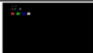
The Grid pattern provides a selection of red, green, blue and white boxes with 2×2 grids within and above them to test for pixel on pixel and color offset issues.
35. Image (2 variations)
The Image pattern is a user customizable test pattern that holds two bitmap images. One image is for use with low output resolutions (below 1920×1080) and the other is for high output resolutions (1920×1080 and above). The low resolution image is a 640×480 bitmap (RGB, 24-bit) and the high resolution image is a 1920×1080 bitmap (RGB, 24-bit).
Note: To upload new images into the unit please the new replacement image on a USB thumb drive with the file named "IMG_480.BMP" or "IMG_1080.BMP" as appropriate. Plug the USB thumb drive into the USB port on the unit and navigate to the "Setup" menu. Next, activate the "Image 640×480 Update" or "Image 1920×1080 Update" menu item, as appropriate, to copy the new image to the unit.
36. Letter H (2 variations)
Big/Small H
The Letter H pattern is a screen filled with a series of large capital “H” characters moving vertically up the screen. This is a basic test to confirm motion detail. There are 2 variations: Large “H” characters and small “H” characters.
37. Line On/Off-H
The Line On/Off-H pattern generates an alternating pattern of single- pixel horizontal white lines. This pattern can be used to analyze the vertical pixel resolution of your display. If the output appears to have mosaic patterns, or appears to be a solid gray field, then it is possible that your display does not fully support the resolution you are currently sending to it.
38. Line On/Off-V (2 variations)
White & Black Lines
Red & Green Lines (Not supported in 4K)
The Line On/Off-V pattern generates an alternating pattern of single-pixel vertical lines. This pattern can be used to analyze the horizontal pixel resolution of your display. If the output appears to have mosaic patterns, or appears to be a solid gray field, then it is possible that your display does not fully support the resolution you are currently sending to it. There are 2 variations: alternating white & black lines and alternating red and green lines.
Note: The red and green variation is not available if the selected output resolution is 4K. The following timings use dual-pixel lines: 3840x2160@50/60Hz & 4096x2160@25/30/50/60Hz.
39. Motion-H (4 variations)
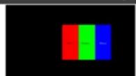
Slow/Fast RGB Block
Slow/Fast String
The Motion-H patterns are a collection of horizontal motion tests. These can be used to test your display's pixel on/off response time. There are 4 variations: Slow red/green/blue block, fast red/green/block, slow moving sample text, fast moving sample text.
Note: The contents of the text can be modified using an RS-232 or telnet command and can be up to 20 characters long.
40. Motion-V (4 variations)
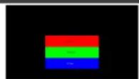
Slow/Fast RGB Block
Slow/Fast String
The Motion-V patterns are a collection of vertical motion tests. These can be used to test your display's pixel on/off response time. There are 4 variations: Slow red/green/blue block, fast red/green/block, slow moving sample text, fast moving sample text.
Note: The contents of the text can be modified using an RS-232 or telnet command and can be up to 20 characters long.
41. Multiburst (3 variations)
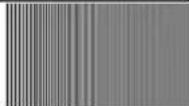
Stop Motion
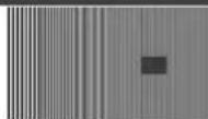
Slow/Fast Motion
The Multiburst pattern provides a standard multiburst pattern consisting of vertical white lines that decrease in thickness from left to right allowing the user to analyze the bandwidth and frequency response of the video path and connected display. There are 3 variations: Standard multiburst, multiburst with a slow moving gray block, and multiburst with a fast moving gray block.
42. Needles
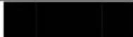
The Needles pattern is a standard needle pulse test. The top half of the screen is black and the bottom half is white with 2 thin inverse-brightness lines crossing from top to bottom. This pattern allows for analysis of the sharpness, blooming and screen distortion issues that a display might have.
43. Overscan
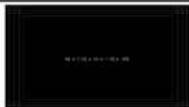
The Overscan pattern provides a quick way to determine how much overscan, or clipping, is being caused by a display. It consists of 5 concentric rectangles moving in from the outer edge of the signal. They are positioned at 0%, 2.5%, 5%, 7.5% and 10% of the screen size.
44. Pluge (2 variations)
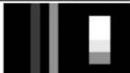
Full/Limited RGB Range
The Pluge pattern is used to perform the accurate and consistent brightness and contrast configuration of a display. Typically you will want to adjust the brightness control of the monitor so that the first bar is just barely indistinguishable from the background black while the second bar is still clearly visible. Next you should adjust the contrast so that all four segments of the greyscale box are clearly visible and distinguishable. There are 2 variations: Full RGB range (0–255) and Limited RGB range (16–235).
45. Square H8 (2 variations)
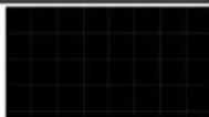
Normal
Inverse
The Square H8 pattern is a full field black & white pattern of squares dividing the screen horizontally into 8 sections. This pattern is primarily used to check projector linearity. There are 2 variations: Normal (white lines, black field) and Inverse (black lines, white field).
46. Square H16 (2 variations)
Normal
Inverse
The Square H16 pattern is a full field black & white pattern of squares dividing the screen horizontally into 16 sections. This pattern is primarily used to check projector linearity. There are 2 variations: Normal (white lines, black field) and Inverse (black lines, white field).
47. Square H32 (2 variations)
Normal
Inverse
The Square H32 pattern is a full field black & white pattern of squares dividing the screen horizontally into 32 sections. This pattern is primarily used to check projector linearity. There are 2 variations: Normal (white lines, black field) and Inverse (black lines, white field).
48. Text (4 variations)
Normal & Small
Inverse & Small
Normal & Big
Inverse & Big
The Text pattern is used to check the clarity of text at various sizes and colors. This is primarily a test for projectors. There are 4 variations: Small multi-color text on a black background, small multi-color text on a white background, large multi-color text on a black background, and large multi-color text on a white background.
49. Window Blue (4 variations)
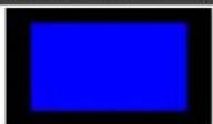
Normal 75%
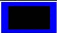
Inverse 75%
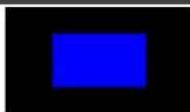
Normal 50%
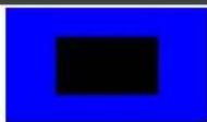
Inverse 50%
50. Window Cyan (4 variations)
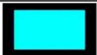
Normal 75%
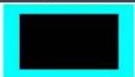
Inverse 75%
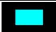
Normal 50%
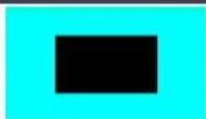
Inverse 50%
51. Window Green (4 variations)
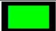
Normal 75%
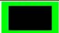
Inverse 75%
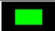
Normal 50%
Inverse 50%
52. Window Magenta (4 variations)
Normal 75%
Inverse 75%
Normal 50%
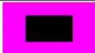
Inverse 50%
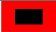
- Window Red (4 variations)
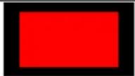
Normal 75%
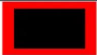
Inverse 75%
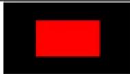
Normal 50%
Inverse 50%
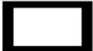
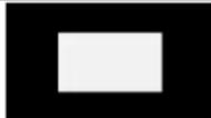
- Window White (4 variations)
Normal 75%
Inverse 75%
Normal 50%

Inverse 50%
- Window Yellow (4 variations)
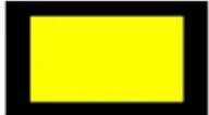
Normal 75%
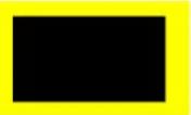
Inverse 75%
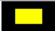
Normal 50%
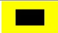
Inverse 50%
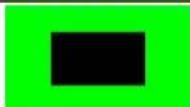
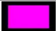
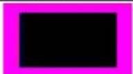
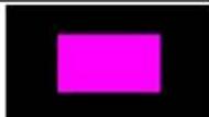
These Window patterns are additional screen purity tests offering seven different patterns with different sized windows of each color on a black field: Blue, Cyan, Green, Magenta, Red, White, Yellow. The color patterns should display an even distribution of brightness and consistent color tone across the screen. Each pattern has 4 variations: Normal 75% Window, Inverse 75% Window, Normal 50% Window, and Inverse 50% Window.
Firmware Upgrade Procedures
The following firmware upgrade procedures are performed via the SERVICE USB connector.
Main Firmware Upgrade
- Save the new firmware file to a memory stick formatted to FAT32. Do not change the name of the file.
- Plug the memory stick into the SERVICE USB connector on 860.
- Using the OSD Menu go to Setup -> Firmware Update submenu.
- Select Yes and confirm by pressing Enter.
- Wait until the upgrade procedure ends on the 860 LCD display.
- In the Information Menu of the OSD, verify the correct version of the upgraded firmware.
Flash Firmware (Patterns and Fonts) Upgrade
- Save the new flash firmware file to a memory stick formatted to FAT32. Do not the change name of the file.
- Switch OFF the 860 power.
- Plug the memory stick into the SERVICE USB connector on 860.
- Press and hold the HDCP ON/OFF button on 860.
- Switch ON the 860 power.
- Release the HDCP ON/OFF button and wait until the upgrade procedure ends on the 860 LCD display.
Default EDID
Monitor
Model name..... 860
Manufacturer..... KMR
Plug and Play ID..... KMR0001
Serial number...... 1
Manufacture date..... 2016, ISO week 14
Filter driver...... None
EDID revision...... 1.3
Input signal type..... Digital
Color bit depth...... Undefined
Display type...... Undefined
Screen size..... 160 x 90 mm (7.2 in)
Power management..... Standby, Suspend, Active off/sleep
Extension blocs..... 1 (CEA-EXT)
DDC/CI...... Not supported
Color characteristics
Default color space..... Non-sRGB
Display gamma.... 2.40
Red chromaticity..... Rx 0.611–Ry 0.329
Green chromaticity..... Gx 0.312–Gy 0.559
Blue chromaticity..... Bx 0.148-By 0.131
White point (default).... Wx 0.320-Wy 0.336
Additional descriptors... None
Timing characteristics
Horizontal scan range.... 15–92kHz
Vertical scan range..... 24–85Hz
Video bandwidth..... 170MHz
CVT standard...... Not supported
GTF standard...... Not supported
Additional descriptors... None
Preferred timing..... Yes
Native/preferred timing.. 1920x1080p at 60Hz (16:9)
Modeline..... "1920x1080" 148.500 1920 2008 2052 2200 1080 1084 1089 1125 +hsync +vsync
Detailed timing #1..... 1280x800p at 60Hz (16:10)
Modeline..... "1280x800" 83.500 1280 1352 1480 1680 800 803 809 831 -hsync +vsync
Standard timings supported
720 x 400p at 70Hz-IBM VGA
640 x 480p at 60Hz–IBM VGA
640 x 480p at 72Hz-VESA
640 x 480p at 75Hz-VESA
800 x 600p at 56Hz-VESA
800 x 600p at 60Hz-VESA
800 x 600p at 72Hz-VESA
800 x 600p at 75Hz-VESA
1024 x 768p at 60Hz-VESA
1024 x 768p at 70Hz-VESA
1024 x 768p at 75Hz-VESA
1280 x 1024p at 75Hz-VESA
1280 x 1024p at 60Hz-VESA STD
1600 x 1200p at 60Hz-VESA STD
1280 x 720p at 60Hz-VESA STD
1600 x 900p at 60Hz-VESA STD
1440 x 900p at 60Hz-VESA STD
1400 x 1050p at 60Hz-VESA STD
1280 x 800p at 60Hz-VESA STD
1680 x 1050p at 60Hz-VESA STD
EIA/CEA-861 Information
Revision number...... 3
IT underscan...... Supported
Basic audio..... Supported
YCbCr 4:4:4.... Supported
YCbCr 4:2:2.... Supported
Native formats..... 1
Detailed timing #1..... 1280x768p at 60Hz (16:9)
Modeline..... "1280x768" 79.500 1280 1344 1472 1664 768 771 778 798 -hsync +vsync
Detailed timing #2..... 1366x768p at 60Hz (4:3)
Modeline...... "1366x768" 85.500 1366 1436 1579 1792 768 771 774 798 +hsync +vsync
Detailed timing #3..... 1920x1200p at 60Hz (16:10)
Modeline..... "1920x1200" 154.000 1920 1968 2000 2080 1200 1203 1209 1235 +hsync -vsync
Detailed timing #4..... 1280x720p at 60Hz (16:9)
Modeline..... "1280x720" 74.250 1280 1390 1430 1650 720 725 730 750 +hsync +vsync
CE video identifiers (VICs)-timing/formats supported
640 x 480p at 60Hz-Default (4:3, 1:1)
720 x 480i at 60Hz-Doublescan (4:3, 8:9)
720 x 480p at 60Hz-EDTV (4:3, 8:9)
1280 x 720p at 60Hz-HDTV (16:9, 1:1) [Native]
1920 x 1080i at 60Hz-HDTV (16:9, 1:1)
1920 x 1080p at 60Hz-HDTV (16:9, 1:1)
720 x 576i at 50Hz-Doublescan (4:3, 16:15)
720 x 576p at 50Hz-EDTV (4:3, 16:15)
1280 x 720p at 50Hz-HDTV (16:9, 1:1)
1920 x 1080i at 50Hz-HDTV (16:9, 1:1)
1920 x 1080p at 50Hz-HDTV (16:9, 1:1)
1920 x 1080p at 24Hz-HDTV (16:9, 1:1)
NB: NTSC refresh rate = (Hz*1000)/1001
CE audio data (formats supported)
LPCM 2-channel, 16/20/24 bit depths at 32/44/48/96/192 kHz
CE vendor specific data (VSDB)
EEE registration number. 0x000C03
CEC physical address..... 1.0.0.0
Maximum TMDS clock..... 165MHz
CE speaker allocation data
Channel configuration.... 2.0
Front left/right..... Yes
Front LFE...... No
Front center.
Rear left/right..... No
Rear center...... No
Front left/right center.. No
Rear left/right center... No
Rear LFE...... No
Report information
Date generated.... 14/11/2016
Software revision..... 2.90.0.1020
Data source...... Real-time 0x0071
Operating system...... 6.1.7601.2.Service Pack 1
Raw data
00,FF,FF,FF,FF,FF,FF,00,4E,84,01,00,01,00,00,00,0E,1A,01,03,80,10,09,8C,FA,9C,20,9C,54,4F,8F,26,
21,52,56,AF,CF,00,81,80,A9,40,81,C0,A9,C0,95,00,90,40,81,00,B3,00,02,3A,80,18,71,38,2D,40,58,2C,
45,00,10,09,00,00,00,1E,9E,20,00,90,51,20,1F,30,48,80,36,00,10,0A,00,00,00,1C,00,00,00,FD,00,18,
55.0F,5C,11,00,0A,20,20,20,20,20,20,20,00,00,00,FC,00,50,41,54,54,45,52,4E,20,47,45,4E,0A,20,01,A8,
02,03,1F,F1,4C,01,06,02,84,05,10,15,11,13,14,1F,20,23,09,57,07,65,03,0C,00,10,00,83,01,00,00,0E,
1F,00,80,51,00,1E,30,40,80,37,00,10,09,00,00,00,1C,66,21,56,AA,51,00,1E,30,46,8F,33,00,04,03,00,
00,00,1E,28,3C,80,A0,70,B0,23,40,30,20,36,00,10,0A,00,00,00,1A,01,1D,00,72,51,D0,1E,20,6E,28,55,
00,10,09,00,00,00,1E,00,00,00,00,00,00,00,00,00,00,00,00,00,00,00,00,00,00,00,00,00,00,42
Technical Specifications
| INPUTS: | 1 HDMI1 unbalanced stereo audio (2Vrms max. / 20kΩ) on a 3.5mm jack1 RS-232 on a 9-pin D-sub connector1 Ethernet on an RJ-45 connector1 USB connector | |
| OUTPUTS: | 1 HDMI1 VGA on a 15-pin HD connector1 unbalanced stereo audio (2Vrms max. / 560Ω) on a 3.5mm jack | |
| COMPLIANCE WITH HDMI STANDARD: | Up to HDMI 2.0 and HDCP 2.2 | |
| CONTROLS: | Panel buttons with OLED display, OSD, RS-232, IR, and Ethernet | |
| MAXIMUM DATA RATE: | 18Gbps (6Gbps per graphic channel) | |
| ESD PROTECTION: | Human body model:±8 kV (air-gap discharge)±4 kV (contact discharge) | |
| OPERATING TEMPERATURE: | 0° to +40°C (32° to 104°F) | |
| STORAGE TEMPERATURE: | -20° to +60°C (-4° to 140°F) | |
| HUMIDITY: | 20% to 90%, RHL non-condensing | |
| POWER CONSUMPTION: | 5V DC, 1.6A | |
| POWER SUPPLY: | 5.2V/4A | |
| DIMENSIONS: | 16.5cm x 13.2cm x 3cm (6.5" x 5.2" x 1.2") W,D,H | |
| WEIGHT: | 0.8kg (1.7lbs) approx. | |
| SHIPPING DIMENSIONS: | 34.5 cm x 16.5cm x 5.2cm (13.6" x 6.5" x 2.0") W,D,H | |
| SHIPPING WEIGHT: | 1.2kg (2.7lbs) approx. | |
| CHASSIS MATERIAL: | Metal | |
| SAFETY REGULATORY COMPLIANCE: | CE | |
| INCLUDED ACCESSORIES: | Remote control (LR-40)5.2V/4A power adaptor | |
| HEAVY DUTY FLIGHT CASE: | External Dimensions: | 30.5cm x 26.9cm x 14.7cm(12" x 10.6" x 5.8") W, D, H |
| Internal Dimensions: | 27.8cm x 20.3cm x 11.5cm(10.9" x 8" x 4.5") W, D, H | |
| Lid Depth: | 3.0cm (1.2") | |
| Bottom Depth: | 8.5cm (3.5") | |
| Material: | Engineer resin and glass fiber | |
| Weight: | 1.5Kg (3.3lbs) | |
| Waterproof Standard: | IP67 | |
| Specifications are subject to change without notice at www.kramerav.com | ||
Supported Color Formats
| Output Resolution (Hz) | RGB | YCbCr4:4:4 | YCbCr4:2:2 | YCbCr4:2:0 | |||||||
| 8 | 10 | 12 | 8 | 10 | 12 | 8 | 12 | 8 | 10 | 12 | |
| 640×350p@85~2048×1080p@60 | √ | √ | √ | √ | √ | √ | √ | ||||
| 3840×2160p@23~30 | √ | √* | √* | √ | √* | √* | |||||
| 4096×2160p@23~30 | |||||||||||
| 3840×2160p@50~60 | √* | √* | √ | √* | √* | ||||||
| 4096×2160p@50~60 | |||||||||||

√ indicates that the specified color depth is supported; √* indicates that the specified color depth is supported and TMDS scrambling is active
Supported Audio Formats
| Audio Source | Sampling Rate (kHz) | Channels | Word Length (Bits) | SD0~3 L/R Freq. (Hz) |
| HDMI Input | Bypass | Bypass | Bypass | Bypass |
| Analog Input | 48 | 2.0 | 16, 20, 24 | Bypass |
| 96 2.0 | ||||
| 192 | 2.0 | |||
| Internal Sinewave | 48 | 2.0, 5.1, 7.1 | 16, 20, 24 | Mute, 200, 400~1600 |
| 96 | 2.0, 5.1, 7.1 | |||
| 192 | 2.0 |
- 48kHz supports a maximum of 2 channels at 2048×1080p@29/30Hz resolution
- 96kHz supports a maximum of 2 channels at 480i, 576i, 480p, 576p, 640×480p@59Hz, 720×400p@70Hz, 1280×768p@60Hz (RB), 1366×768p@60Hz (RB), 2048×1080p@29/30/59/60Hz, 4096×2160p@29/30Hz resolutions
- 192kHz is not supported at 1366×768p@60Hz (RB) or 2048×1080p@29/30Hz resolution
Default Communication Parameters
| RS-232 | |
| Baud Rate | 115200 |
| Data Bits | 8 |
| Stop Bits | 1 |
| Parity | None |
| Flow Control | None |
| Ethernet | |
| To reset the IP settings to the factory reset values go to: Menu-> Setup-> Ethernet Reset-> Change the option to YES and press Enter | |
| IP Address: | 192.168.1.39 |
| Subnet mask: | 255.255.0.0 |
| Default gateway: | 0.0.0.0 |
| TCP Port #: | Not supported |
| Default UDP Port #: | Not supported |
| Maximum UDP Ports: | Not supported |
| Full Factory Reset | |
| OSD | Go to: Menu-> Setup-> Factory Reset->Change the option to Yes and press Enter |
| Top Panel Press and hold the ANAL | YZER / PATTERN button while powering the device on |
| Telnet Command | factory |
| RS-232/Telnet Command | |
| Command Format: | Telnet |
| Example (display the Ethernet link status): | net_link? |
Telnet Control
The 860 can be controlled via RS-232 and Telnet commands over Ethernet. Before attempting to use Telnet control, please ensure that both the unit and the PC/Laptop are connected to the same active network.
For information on connecting via RS-232, see Connecting to the 860 via RS-232 on page 9. For information on connecting via Ethernet, see Connecting to the 860 via Ethernet on page 9.
The device IP address can be found in the Ethernet OSD menu (see Using the OSD Menu on page 14). The default IP address is 192.168.1.39.
Accessing Telnet
To access Telnet:
-
In Windows 7: Click Start, type cmd in the search field and press Enter.
In Windows XP: Click Start > Run, type cmd and press Enter.
In Mac OS X: Click Go > Applications > Utilities > Terminal.
The Command Line Interface (CLI) appears. -
Type telnet [device IP address] and press Enter. For example:
![Administrator: C:\Windows\system32\cmd.exe Microsoft Windows [Version 6.1.7601] Copyright (c) 2009 Microsoft Corporation. All rights reserved. C:\Users\wtarnopolsky>telnet 192.168.73.4](/content/2026/05/1015477/images/a046d8b4f8745267836dca4b677fcd72939f76daa672ec1c6fa52f070b35bd88.jpg)
The device can now be controlled via Telnet.
- Type \help or \? to list all the available commands, for example (The figure below is for illustration purposes only. It does not show all available Telnet commands.):
![$boot [go] $boot7 $edid_copy_sink [c1/c2"c10] $edid_name [c1/c2"c10],[name] Max. 20 Char $edid_name? [d1/d2"d10/c1/c2"c10] $edid_read [d1/d2"d10/c1/c2"c10/sink],[block0/1] $edid_rx [d1/d2"d10/c1/c2"c10/sink] $edid_write [c1/c2"c10/sink_h/sink_v],[block0/block1][128Byte data] $err $factory $fuser7? $hdcp_in_sw [off/on] $hdcp_in_sur7? $hdcp_in_detect7? $hdcp_in_ver [v1.4/v1.4*v2.2] $hdcp_in_ver7? $hdcp_out_sw [off/on] $hdcp_out_sw7? $hdcp_out_ver [v1.4/v2.2] $hdcp_out_ver7? $help $Y $mode1? $motion_text [text] Max. 20 Char $motion_text7? $met_gate7? $met_ip7? $met_ip_mode [dhcp/static] $met_ip_mode7? $met_link7? $met_nac7? $met_mask7? $met_static_gate [xxx.xxx.xxx.xxx] $met_static_gate7? $met_static_ip [xxx.xxx.xxx.xxx] $met_static_ip7? $met_static_mask [xxx.xxx.xxx.xxx] $met_static_mask7? $pattern [1/2/3/~/] $pattern7? $task_mode [analyser/pattern] $task_mode7? $timing [1/2/3/~/] $timing7? $update_fw $update_ing480 $update_ing1880](/content/2026/05/1015477/images/4a6e9103bdbf6bb4ef4a6db56cd33a4424a4716bbe89883e512401cca641e3ad.jpg)

Commands will not be executed unless followed by a carriage return. Commands are not case-sensitive. If the IP address is changed, the IP address required for Telnet access also changes, accordingly.
RS-232 and Telnet Commands
Before using the RS-232 and Telnet commands, please note the following:
- All commands must start with the \$ character or the command will not be recognized by the unit.
- Commands are not case-sensitive.
- Commands must end with a carriage return (0x0D). Use of a line feed (0x0A) is optional.
- The [ and ] characters are placed around variable command parameters where there is a choice of more than one item. Please type the selected parameter without the [ and ] characters when entering the command.
- The unit responds to most commands with a repetition of the original command followed by the specified parameters or requested information except where otherwise noted. If an invalid command is entered, the unit responds with \$err.
- All unit responses end with a carriage return (0x0D) + line feed (0x0A).
- Only one command may be processed at a time. Do not send additional commands until the response from the previous command has been received.
• To disconnect and exit Telnet: Press Ctrl+1 and Enter.
The following table lists the available commands.
| Command | Description |
| audio_ch [2/6/8] | Set output int. (internal sinewave audio) audio channel number: 2 (ch 2) / 6 (ch 5.1) / 8 (ch 7.1) |
| audio_ch? | Get output int. audio channel number |
| audio_freq[sd0_l/sd0_r/sd1_l/sd1_r/sd2_l/sd2_r/sd3_l/sd3_r],[mute/200/400/600/800/1000/1200/1400/1600] | Set output int. audio frequency: SD0-3 L/R in Hz. |
| audio_freq?[sd0_l/sd0_r/sd1_l/sd1_r/sd2_l/sd2_r/sd3_l/sd3_r] | Get output int. audio frequency: SD0-3 L/R in Hz |
| audio_mute [off/on] | Set output audio mute: off, on. |
| audio_mute? | Get output audio mute status. |
| audio_source [ana/hdmi/int] | Set output audio source: analog in, hdmi in, internal. |
| audio_source? | Get output audio source. |
| audio_sr [48/96/192] | Set output int. audio sampling rate in KHz. |
| audio_sr? | Get output int. audio sampling rate. |
| audio_vol [0/1/2/...80] | Set output audio volume. |
| audio_vol? | Get output audio volume. |
| boot go | Reboot the unit. During the boot process the unit won't respond to commands. |
| boot? | Display the boot status. |
| color_space[rgb/y444/y422/y420] | Set output color space. |
| color_space? | Get output color space. |
| deep_color [8/10/12] | Set output deep color depth. |
| deep_color? | Get output deep color depth. |
| edid_copy_sink [cl-c10] | Copy the HDMI sink's EDID to a copy slot (C1-C10). (If the copy fails "err" is displayed.) |
| edid_manuf?[rx/sink_h/sink_v] | Get manufacturer name for: rx, sink HDMI or sink VGA EDID.If reading the EDID fails, "err_ddc" is displayed.If wrong EDID contents found, "err_bad" is displayed. |
| edid_model?[rx/sink_h/sink_v] | Get model name (monitor name) for: rx,sink HDMI or sink VGA EDID.If reading the EDID fails, "err_ddc" is displayed.If wrong EDID contents found, "err_bad" is displayed. |
| edid_name [c1/c2...c10], [name] | Set the name of EDID Copy1-10.Maximum name length is 20 characters. |
| edid_name?[d1/d2~d10/c1/c2...c10] | Get name of EDID Default1-10, Copy1-10. |
| edid_native?[rx/sink_h/sink_v] | Get EDID native resolution for: rx, sink HDMI or sink VGA.(The first detailed timing in block 0).If reading the EDID fails, "err_ddc" is displayed.If wrong EDID contents found, "err_bad" is displayed. |
| edid_read [d1-d10/c1-c10/sink_h/sink_v],block[0/1] | Displays selected data block from the selected EDID slot.The data is output as a bitstream of 128 hex data following the CR+LF within the response.The hex data is in 3 digits: The first two digits are hex values and the third digit is am ASCII space (0x20). |
| edid_rx [d1-d10/c1-c10/sink] | Select the EDID to use on the unit's HDMI input. |
| edid_rx? | Display the current RX EDID selection. |
| edid_type?[rx/sink_h/sink_v] | Get EDID type for: rx, sink HDMI or sink VGA.If reading the EDID fails, "err_ddc" is displayed.If wrong EDID contents found, "err_bad" is displayed. |
| edid_write[c1-c10/sink_h/sink_v],block[0/1]<CR><LF>[128 hex data] | Directly write an EDID block to one of the copy slots (C1~C10), sink HDMI or sink VGA.The data must be sent as a bitstream of 128 hex data following the CR+LF in the command.The hex data is in 3 digits: The first two digits are hex values and the third digit is an ASCII space (0x20). |
| factory | Perform a factory reset & restart the unit. |
| #FCT-SN [serial_number] | Set serial_number: 14 digits. |
| fwver? | Display the current firmware version. |
| hdcp_in_sw [off/on] | Turn HDCP on/off on the input port (Analyzer mode only). |
| hdcp_in_sw? | Display the HDCP on/off setting for the input port. |
| hdcp_in_detect? | Detect the HDCP status of the source. |
| hdcp_in_ver [v1.4/v1.4+v2.2] | Set the HDCP version to use on the input port (Analyzer mode only). |
| hdcp_in_ver? | Display the current HDCP version on the input port. |
| hdcp_out_sw [off/on] | Turn HDCP on/off on the output port (Pattern mode only). |
| hdcp_out_sw? | Get the HDCP output communication status. A status of "Talk" means it's currently performing handshaking. |
| hdcp_out_ver [v1.4/v2.2] | Set the HDCP version to use on the output port (Pattern mode only). |
| hdcp_out_ver? | Display the current HDCP version on the output port. |
| hdr_eotf [sdr/hdr/2084/rsvd] | Set HDR EOTF. |
| hdr_eotf? | Get HDR EOTF. |
| hdr_mcll[0/100/200/...65500] | Set HDR Max. Content Light Level. |
| hdr_mcll? | Get HDR Max. Content Light Level. |
| hdr_mfall[0/100/200/...65500] | Set HDR Max. Frame average Light Level. |
| hdr_mfall? | Get HDR Max. Frame-average Light Level. |
| hdr_set [1/2/3] | Select HDR settings. |
| hdr_set? | Get HDR settings. |
| hdr_sw [off/on] | Set HDR on/off. |
| hdr_sw? | Get HDR on/off status. |
| hdr_tx_col [1/2/...10] | Set TX AVI Colorimetry:No Data (1)ITU601 (2)ITU709 (3)xVYCC601 (4)xVYCC709 (5)sYCC601 (6)AdobeY601 (7)Adobe RGB (8)BT.2020(1) Y'CC'BCC'RC" (9)BT.2020(2) R'G'B' or Y'C'BC'R" (10) |
| hdr_tx_col? | Get TX AVI Colorimetry. |
| help | Show command list. |
| ? | Show command list. |
| model? | Display model number. |
| motion_text [text] | Set text for Motion-H and Motion-V patterns. The maximum length of the text is 20 characters. |
| motion_text? | Display the text used for Motion-H and Motion-V patterns. |
| net_gate? | Display the gateway address. |
| net_ip? | Display the IP address. |
| net_ip_mode [dhcp/static] | Set the IP mode. |
| net_ip_mode? | Display the IP mode status. |
| net_link? | Display the Ethernet link status. |
| net_mac? | Display the Ethernet MAC address. |
| net_mask? | Display the netmask address. |
| net_static_gate[xxx.xxx.xxx.xxx] | Set the static gateway address. |
| net_static_gate? | Display the static gateway address. |
| net_static_ip[xxx.xxx.xxx.xxx] | Set the static IP address. |
| net_static_ip? | Display the static IP address. |
| net_static_mask[xxx.xxx.xxx.xxx] | Set the static netmask address. |
| net_static_mask? | Display the static netmask address. |
| pattern [1/2/3/~] | Select a test pattern to show (P01, P02, P03, and so on). |
| pattern? | Display the current test pattern selection. |
| rx_ddc [off/on] | Set rx port DDC bus. |
| rx_ddc? | Get rx port DDC bus. |
| rx_hotplug [off/on/toggle] | Set rx port hotplug: low (off), high (on) or low >high (toggle) |
| rx_hotplug? | Get rx port hotplug status. |
| rx_hotplug_t[50/100/150/...500] | Set rx port hotplug time in milli-seconds. |
| rx_hotplug_t? | Get rx port hotplug time in milli-seconds. |
| rx_pc_tol [1/2/...10] | Set PC source clock detection tolerance. |
| rx_pc_tol? | Get PC source clock detection tolerance. |
| rx_scdc [off/on] | Set rx port scdc (Status and Control Data Channel). |
| rx_scdc? | Get rx port scdc. |
| rx_sense [off/on] | Set rx port sense. |
| rx_sense? | Get rx port sense. |
| sink_detect?[hotplug/rsense] | Get sink monitor status for: hotplug or receiver sense. |
| sink_detect?[hdcp/aksv/bksv/rxid] | Get HDCP output monitor HDCP port status for: HDCP, AKSV, BKSV, or receiver ID. |
| sink_detect? [scdc/scdc scr enable/scdc scr status/scdc sink ver/scdc source ver] | Get SCDC Output Monitor SCDC port status for: SCDC port status, scrambling enable, sink version, or source version. |
| #SN? | Get serial_number:14 digits. |
| source_detect? [5v/ckdt/data rate/tmds format/scdt] | Get sync input monitor source status for: 5V, TMDS clock detection, video data rate detection, TMDS format, or TMDS sync detection. |
| source_detect?[hdcp/aksv/bksv/rxid] | Get HDCP input monitor HDCP status for: HDCP, AKSV, BKSV, or receiver ID. |
| source_detect?[ha/hbp/hf/ha/hbp/hfp/hsw/ht/hsp,+/-/hvs_offset1/hvs_offset2/pixel_clock/scan,p/i/timing,1/2/...254/timingx,640x480p59/.../tmds_clock/va/vbp/vfp/vsw/vt/vsp] | Get video timing.ha - horizontal active pixelshbp - horizontal back porch pixelshp - horizontal front porch pixelshw - horizontal sync. width pixelshp,+/- - horizontal sync. Polarity, positive/negativehvs_offset1 - h/v sync offset1 in dot (pixels)hvs_offset2 - h/v sync offset2 in dot (pixels)pixel_clock - pixel clock in KHzscan,p/i - video scan mode, p=progressive, i=interlacetiming - displays resolution as an ID code:1/2/.../92/254 - video timing.(see Source Video Resolutions on page 50)timing - displays resolution as text:640x480p59/...(see Source Video Resolutions on page 50)tmds_clock - tmds clock in KHzva - vertical active linesvbp - vertical back porch linesvfp - vertical front porch linesvsw - vertical sync. width linesvt - vertical total linesvsp,+/- - vertical sync. Polarity, positive/negative |
| source_detect?[acr/acr_cts/acr_n/asp/asp_ch/asp_fifo/asp_layout/asp_pll/chs_code/chs_sr/chs_ss/chs_type/hbr/aif] | Get audio timing. |
| source_detect?[aif/avi/drmi/gcp/spd/vsi] | Get packet data. |
| source_detect?[scdc_scr_enable/scdc_scr_status/scdc_sink_ver/scdc_source_ver] | Get SCDC input monitor scrambling status. |
| task_mode [analyser/pattern] | Set the unit's operation mode. |
| task_mode? | Display the unit's current operation mode. |
| timing [1/2/3/~] | Select the output resolution timing to use. (T01, T02, T03, and so on). |
| timing? | Display the unit's current output resolution timing selection. |
| timingx? | Get output video timing selection. |
| tmds_format [dvi/hdmi] | Set TMDS output format. |
| tmds_format? | Get TMDS output format. |
| tmds_sw [off/on] | Set TMDS output off / on. |
| tmds_sw? | Get TMDS output status. |
| tx_5v [follow/on] | Set output +5v-pin: on (always on)/off (follows TMDS out). |
| tx_5v? | Get output +5v-pin status. |
| update_fw | Update the firmware from USB & reboot the unit.Warning: Do not disconnect power to the unit while a firmware update is in progress. |
| update_img480 | Update the 640×480 image from USB & reboot the unit. |
| update_img1080 | Update the 1920×1080 image from USB & reboot the unit. |
Source Video Resolutions
The following table shows the ID codes used by the \$source_detect command for resolution values.
| Source Resolution | Vf | ID |
| 640x350p | 85 1 | |
| 640x480p | 59 2 | |
| 72 3 | ||
| 75 4 | ||
| 85 5 | ||
| 720x400p | 70 6 | |
| 85 7 | ||
| 800x600p | 56 8 | |
| 60 9 | ||
| 72 10 | ||
| 75 11 | ||
| 85 12 | ||
| 848x480p | 60 13 | |
| 1024x768p | 60 14 | |
| 70 15 | ||
| 75 16 | ||
| 85 17 | ||
| 1152x864p | 70 18 | |
| 75 19 | ||
| 85 20 | ||
| 1280x768p | 60rb 21 | |
| 60 22 | ||
| 75 23 | ||
| 85 24 | ||
| 1280x800p | 60rb 25 | |
| 60 26 | ||
| 75 27 | ||
| 85 28 | ||
| 1280x960p | 60 29 | |
| 85 30 | ||
| 1280x1024p | 60 31 | |
| 75 32 | ||
| 85 33 | ||
| 1360x768p | 60 34 | |
| 1366x768p | 60rb 35 | |
| 60 36 | ||
| 1400x1050p | 60rb 37 | |
| 60 38 |
| Source Resolution | Vf | ID |
| 480p | 59 48 | |
| 60 49 | ||
| 576i | 50 50 | |
| 576p | 50 51 | |
| 720p | 25 52 | |
| 29 53 | ||
| 30 54 | ||
| 50 55 | ||
| 59 56 | ||
| 60 57 | ||
| 1080i | 50 58 | |
| 59 59 | ||
| 60 60 | ||
| 1080p | 23 61 | |
| 24 62 | ||
| 25 63 | ||
| 29 64 | ||
| 30 65 | ||
| 50 66 | ||
| 59 67 | ||
| 60 68 | ||
| 2048x1080p | 23 69 | |
| 24 70 | ||
| 25 71 | ||
| 29 72 | ||
| 30 73 | ||
| 50 74 | ||
| 59 75 | ||
| 60 76 | ||
| 3840x2160p | 23 77 | |
| 24 78 | ||
| 25 79 | ||
| 29 80 | ||
| 30 81 | ||
| 50 82 | ||
| 59 83 | ||
| 60 84 | ||
| 4096x2160p | 23 85 |
| Source Resolution | Vf | ID |
| 1440x900p | 60rb 39 | |
| 60 40 | ||
| 1600x900p | 60rb 41 | |
| 1600x1200p | 60 42 | |
| 1680x1050p | 60rb 43 | |
| 60 44 | ||
| 1920x1200p | 60rb 45 | |
| 480i | 59 46 | |
| 60 47 |
| Source Resolution | Vf | ID |
| 24 86 | ||
| 25 87 | ||
| 29 88 | ||
| 30 89 | ||
| 50 90 | ||
| 59 91 | ||
| 60 92 | ||
| No Signal | no_source | |
| Not Supported | 254 | |
rb = Reduced Blanking
The warranty obligations of Kramer Electronics Inc. ("Kramer Electronics") for this product are limited to the terms set forth below:
What is Covered
This limited warranty covers defects in materials and workmanship in this product.
What is Not Covered
This limited warranty does not cover any damage, deterioration or malfunction resulting from any alteration, modification, improper or unreasonable use or maintenance, misuse, abuse, accident, neglect, exposure to excess moisture, fire, improper packing and shipping (such claims must be presented to the carrier), lightning, power surges, or other acts of nature. This limited warranty does not cover any damage, deterioration or malfunction resulting from the installation or removal of this product from any installation, any unauthorized tampering with this product, any repairs attempted by anyone unauthorized by Kramer Electronics to make such repairs, or any other cause which does not relate directly to a defect in materials and/or workmanship of this product. This limited warranty does not cover cartons, equipment enclosures, cables or accessories used in conjunction with this product. Without limiting any other exclusion herein, Kramer Electronics does not warrant that the product covered hereby, including, without limitation, the technology and/or integrated circuit(s) included in the product, will not become obsolete or that such items are or will remain compatible with any other product or technology with which the product may be used.
How Long this Coverage Lasts
The standard limited warranty for Kramer products is seven (7) years from the date of original purchase, with the following exceptions:
- All Kramer VIA hardware products are covered by a standard three (3) year warranty for the VIA hardware and a standard three (3) year warranty for firmware and software updates.
- All Kramer fiber optic cables, adapter-size fiber optic extenders, active cables, cable retractors, all Kramer speakers and Kramer touch panels are covered by a standard one (1) year warranty.
- All Kramer Cobra products, all Kramer Calibre products, all Kramer Minicom digital signage products, all HighSecLabs products, all streaming, and all wireless products are covered by a standard three (3) year warranty.
- All Sierra Video MultiViewers are covered by a standard five (5) year warranty.
- Sierra switchers & control panels are covered by a standard seven (7) year warranty (excluding power supplies and fans that are covered for three (3) years).
- K-Touch software is covered by a standard one (1) year warranty for software updates.
- All Kramer passive cables are covered by a ten (10) year warranty.
Who is Covered
Only the original purchaser of this product is covered under this limited warranty. This limited warranty is not transferable to subsequent purchasers or owners of this product.
What Kramer Electronics Will Do
Kramer Electronics will, at its sole option, provide one of the following three remedies to whatever extent it shall deem necessary to satisfy a proper claim under this limited warranty:
- Elect to repair or facilitate the repair of any defective parts within a reasonable period of time, free of any charge for the necessary parts and labor to complete the repair and restore this product to its proper operating condition. Kramer Electronics will also pay the shipping costs necessary to return this product once the repair is complete.
- Replace this product with a direct replacement or with a similar product deemed by Kramer Electronics to perform substantially the same function as the original product.
- Issue a refund of the original purchase price less depreciation to be determined based on the age of the product at the time remedy is sought under this limited warranty.
What Kramer Electronics Will Not Do Under This Limited Warranty
If this product is returned to Kramer Electronics or the authorized dealer from which it was purchased or any other party authorized to repair Kramer Electronics products, this product must be insured during shipment, with the insurance and shipping charges prepaid by you. If this product is returned uninsured, you assume all risks of loss or damage during shipment. Kramer Electronics will not be responsible for any costs related to the removal or re-installation of this product from or into any installation. Kramer Electronics will not be responsible for any costs related to any setting up this product, any adjustment of user controls or any programming required for a specific installation of this product.
How to Obtain a Remedy Under This Limited Warranty
To obtain a remedy under this limited warranty, you must contact either the authorized Kramer Electronics reseller from whom you purchased this product or the Kramer Electronics office nearest you. For a list of authorized Kramer Electronics resellers and/or Kramer Electronics authorized service providers, visit our web site at www.kramerav.com or contact the Kramer Electronics office nearest you.
In order to pursue any remedy under this limited warranty, you must possess an original, dated receipt as proof of purchase from an authorized Kramer Electronics reseller. If this product is returned under this limited warranty, a return authorization number, obtained from Kramer Electronics, will be required (RMA number). You may also be directed to an authorized reseller or a person authorized by Kramer Electronics to repair the product. If it is decided that this product should be returned directly to Kramer Electronics, this product should be properly packed, preferably in the original carton, for shipping. Cartons not bearing a return authorization number will be refused.
Limitation of Liability
THE MAXIMUM LIABILITY OF KRAMER ELECTRONICS UNDER THIS LIMITED WARRANTY SHALL NOT EXCEED THE ACTUAL PURCHASE PRICE PAID FOR THE PRODUCT. TO THE MAXIMUM EXTENT PERMITTED BY LAW, KRAMER ELECTRONICS IS NOT RESPONSIBLE FOR DIRECT, SPECIAL, INCIDENTAL OR CONSEQUENTIAL DAMAGES RESULTING FROM ANY BREACH OF WARRANTY OR CONDITION, OR UNDER ANY OTHER LEGAL THEORY. Some countries, districts or states do not allow the exclusion or limitation of relief, special, incidental, consequential or indirect damages, or the limitation of liability to specified amounts, so the above limitations or exclusions may not apply to you.
Exclusive Remedy
TO THE MAXIMUM EXTENT PERMITTED BY LAW, THIS LIMITED WARRANTY AND THE REMEDIES SET FORTH ABOVE ARE EXCLUSIVE AND IN LIEU OF ALL OTHER WARRANTIES, REMEDIES AND CONDITIONS, WHETHER ORAL OR WRITTEN, EXPRESS OR IMPLIED. TO THE MAXIMUM EXTENT PERMITTED BY LAW, KRAMER ELECTRONICS SPECIFICALLY DISCLAIMS ANY AND ALL IMPLIED WARRANTIES, INCLUDING, WITHOUT LIMITATION, WARRANTIES OF MERCHANTABILITY AND FITNESS FOR A PARTICULAR PURPOSE. IF KRAMER ELECTRONICS CANNOT LAWFULLY DISCLAIM OR EXCLUDE IMPLIED WARRANTIES UNDER APPLICABLE LAW, THEN ALL IMPLIED WARRANTIES COVERING THIS PRODUCT, INCLUDING WARRANTIES OF MERCHANTABILITY AND FITNESS FOR A PARTICULAR PURPOSE, SHALL APPLY TO THIS PRODUCT AS PROVIDED UNDER APPLICABLE LAW. IF ANY PRODUCT TO WHICH THIS LIMITED WARRANTY APPLIES IS A "CONSUMER PRODUCT" UNDER THE MAGNUSON-MOSS WARRANTY ACT (15 U.S.C.A. §2301, ET SEQ.) OR OTHER APPLICABLE LAW, THE FOREGOING DISCLAIMER OF IMPLIED WARRANTIES SHALL NOT APPLY TO YOU, AND ALL IMPLIED WARRANTIES ON THIS PRODUCT, INCLUDING WARRANTIES OF MERCHANTABILITY AND FITNESS FOR THE PARTICULAR PURPOSE, SHALL APPLY AS PROVIDED UNDER APPLICABLE LAW.
Other Conditions
This limited warranty gives you specific legal rights, and you may have other rights which vary from country to country or state to state.
This limited warranty is void if (i) the label bearing the serial number of this product has been removed or defaced, (ii) the product is not distributed by Kramer Electronics or (iii) this product is not purchased from an authorized Kramer Electronics reseller. If you are unsure whether a reseller is an authorized Kramer Electronics reseller, visit our web site at www.kramerav.com or contact a Kramer Electronics office from the list at the end of this document.
Your rights under this limited warranty are not diminished if you do not complete and return the product registration form or complete and submit the online product registration form. Kramer Electronics thanks you for purchasing a Kramer Electronics product. We hope it will give you years of satisfaction.




P/N:

2900-300647
Rev:

7

SAFETY WARNING
Disconnect the unit from the power supply before opening and servicing
For the latest information on our products and a list of Kramer distributors, visit our Web site where updates to this user manual may be found.
We welcome your questions, comments, and feedback.
- Overview 3
- Connecting the 860 8
- Operating the 860 12
- Test Timings and Patterns 26
- Firmware Upgrade Procedures 38
- Default EDID 39
- Technical Specifications 41
- Telnet Control 44
- Introduction
- Getting Started
- Achieving the Best Performance
- Safety Instructions DC
- Recycling Kramer Products
- Overview
- The 860 features:
- Defining the 860 HDMI 18G Signal Generator & Analyzer
- Connecting the 860
- Connecting to the 860 via RS-232
- Connecting to the 860 via Ethernet
- Connecting the Ethernet Port Directly to a PC
- Connecting the Ethernet Port via a Network Hub or Switch
- Configuring the Ethernet Port
- Operating the 860
- Using the OLED Display
- Using the Remote Control
- To connect a serial controller to the 860:
- Using the OSD Menu
- Understanding Analyzer Mode Information
- Source Monitor
- SCDC Input Monitor
- Test Timings and Patterns
- Test Patterns
- Border
- Checkerboard
- 3.Circle 1
- Circle 4
- Black
- Magenta
- Colorbar Delay
- Colorbar-H
- Colorbar Motion
- Colorbar S.
- Colorbar Split
- Colorbar-V (3 variations)
- Cross Hatch 8 (2 variations)
- Cross Hatch 16 (2 variations)
- Cross Hatch 32 (2 variations)
- Diagonal 1
- Diagonal 2
- Dot
- General (3 variations)
- Grayscale 8 (3 variations)
- Grayscale 16 (3 variations)
- Grayscale 32 (3 variations)
- Grayscale 64 (3 variations)
- Grayscale 256 (4 variations)
- Grayscale 256RGB
- Grayscale Adjust (254 variations)
- Grayscale H
- Grid
- Image (2 variations)
- Letter H (2 variations)
- Line On/Off-H
- Line On/Off-V (2 variations)
- Motion-H (4 variations)
- Motion-V (4 variations)
- Multiburst (3 variations)
- Needles
- Overscan
- Pluge (2 variations)
- Square H8 (2 variations)
- Square H16 (2 variations)
- Square H32 (2 variations)
- Text (4 variations)
- Window Blue (4 variations)
- Window Cyan (4 variations)
- Window Green (4 variations)
- Window Magenta (4 variations)
- Firmware Upgrade Procedures
- Main Firmware Upgrade
- Flash Firmware (Patterns and Fonts) Upgrade
- Default EDID
- Monitor
- Color characteristics
- Timing characteristics
- Standard timings supported
- EIA/CEA-861 Information
- Telnet Control
- Accessing Telnet
- To access Telnet:
- RS-232 and Telnet Commands
- Source Video Resolutions
- What is Covered
- What is Not Covered
- How Long this Coverage Lasts
- Who is Covered
- What Kramer Electronics Will Do
- What Kramer Electronics Will Not Do Under This Limited Warranty
- How to Obtain a Remedy Under This Limited Warranty
- Limitation of Liability
- Exclusive Remedy
- Other Conditions
Brand : Kramer
Model : 860
Category : Measurement