
X14SBW-TF - Computer Supermicro - Free user manual and instructions
Find the device manual for free X14SBW-TF Supermicro in PDF.


| Product Type | Motherboard |
| Brand | Supermicro |
| Model | X14SBW-TF |
| Form Factor | E-ATX |
| CPU Socket | LGA 4677 |
| Supported Processors | Intel Xeon Scalable (4th Gen) |
| Chipset | Intel C741 |
| Memory Slots | 16 x DIMM |
| Memory Type | DDR5 ECC RDIMM |
| Max Memory Capacity | 2 TB |
| Expansion Slots | 4 x PCIe 5.0 x16, 2 x PCIe 5.0 x8 |
| Storage Interfaces | 8 x SATA3, 4 x M.2 NVMe |
| Networking | 2 x 10GbE, 2 x 1GbE |
| Power Connectors | 24-pin ATX, 2 x 8-pin EPS12V |
| Dimensions | 305 mm x 330 mm |
| Weight | 1.2 kg |
| Operating Temperature | 10°C to 35°C |
| BIOS Type | AMI UEFI |
| IPMI Support | Yes (BMC) |
| Security Features | TPM 2.0, Secure Boot, Intel SGX |
Frequently Asked Questions - X14SBW-TF Supermicro
User questions about X14SBW-TF Supermicro
0 question about this device. Answer the ones you know or ask your own.
Ask a new question about this device
Download the instructions for your Computer in PDF format for free! Find your manual X14SBW-TF - Supermicro and take your electronic device back in hand. On this page are published all the documents necessary for the use of your device. X14SBW-TF by Supermicro.
USER MANUAL X14SBW-TF Supermicro
The information in this User's Manual has been carefully reviewed and is believed to be accurate. The vendor assumes no responsibility for any inaccuracies that may be contained in this document, and makes no commitment to update or to keep current the information in this manual, or to notify any person or organization of the updates. Note: For the most up-to-date version of this manual, see our website at https://www.supermicro.com.
Super Micro Computer, Inc. ("Supermicro") reserves the right to make changes to the product described in this manual at any time and without notice. This product, including software and documentation, is the property of Supermicro and/or its licensors, and is supplied only under a license. Any use or reproduction of this product is not allowed, except as expressly permitted by the terms of said license.
IN NO EVENT WILL Super Micro Computer, Inc. BE LIABLE FOR DIRECT, INDIRECT, SPECIAL, INCIDENTAL, SPECULATIVE OR CONSEQUENTIAL DAMAGES ARISING FROM THE USE OR INABILITY TO USE THIS PRODUCT OR DOCUMENTATION, EVEN IF ADVISED OF THE POSSIBILITY OF SUCH DAMAGES. IN PARTICULAR, SUPER MICRO COMPUTER, INC. SHALL NOT HAVE LIABILITY FOR ANY HARDWARE, SOFTWARE, OR DATA STORED OR USED WITH THE PRODUCT, INCLUDING THE COSTS OF REPAIRING, REPLACING, INTEGRATING, INSTALLING OR RECOVERING SUCH HARDWARE, SOFTWARE, OR DATA.
Any disputes arising between manufacturer and customer shall be governed by the laws of Santa Clara County in the State of California, USA. The State of California, County of Santa Clara shall be the exclusive venue for the resolution of any such disputes. Supermicro's total liability for all claims will not exceed the price paid for the hardware product.
FCC Statement: This equipment has been tested and found to comply with the limits for a Class A or Class B digital device pursuant to Part 15 of the FCC Rules. These limits are designed to provide reasonable protection against harmful interference when the equipment is operated in industrial environment for Class A device or in residential environment for Class B device. This equipment generates, uses, and can radiate radio frequency energy and, if not installed and used in accordance with the manufacturer's instruction manual, may cause harmful interference with radio communications. Operation of this equipment in a residential area is likely to cause harmful interference, in which case you will be required to correct the interference at your own expense.
California Best Management Practices Regulations for Perchlorate Materials: This Perchlorate warning applies only to products containing CR (Manganese Dioxide) Lithium coin cells. "Perchlorate Material-special handling may apply. See https://www.dtsc.ca.gov/hazardouswaste/perchlorate".

WARNING: This product can expose you to chemicals including lead, known to the State of California to cause cancer and birth defects or other reproductive harm. For more information, go to https://www.P65Warnings.ca.gov.

The products sold by Supermicro are not intended for and will not be used in life support systems, medical equipment, nuclear facilities or systems, aircraft, aircraft devices, aircraft/emergency communication devices or other critical systems whose failure to perform be reasonably expected to result in significant injury or loss of life or catastrophic property damage. Accordingly, Supermicro disclaims any and all liability, and should buyer use or sell such products for use in such ultra-hazardous applications, it does so entirely at its own risk. Furthermore, buyer agrees to fully indemnify, defend and hold Supermicro harmless for and against any and all claims, demands, actions, litigation, and proceedings of any kind arising out of or related to such ultra-hazardous use or sale.
Manual Revision 1.0
Release Date: October 09, 2024
Unless you request and receive written permission from Super Micro Computer, Inc., you may not copy any part of this document. Information in this document is subject to change without notice. Other products and companies referred to herein are trademarks or registered trademarks of their respective companies or mark holders.
Copyright © 2024 by Super Micro Computer, Inc.
All rights reserved.
Published in the United States of America
Preface
About This Manual
This manual is written for professional system integrators and PC technicians. It provides information for the installation and use of the X14SBW-F/-TF motherboard. Installation and maintenance should be performed by certified service technicians only.
Notes
For your system to work properly, follow the links below to download all necessary drivers/utilities and the user's manual for your server.
• Supermicro product manuals: https://www.supermicro.com/support/manuals
• Product drivers and utilities: https://www.supermicro.com/wdl
- Product safety info: https://www.supermicro.com/about/policies/safety_information.cfm
- A secure data deletion tool designed to fully erase all data from storage devices can be found on our website: https://www.supermicro.com/about/policies/disclaimer.cfm?url=/wdl/utility/Lot9_Secure_Data_Deletion_Utility
- If you have any questions, contact our support team. Region-specific Technical Support email addresses can be found at: "Contacting Supermicro" on page 10
- If you have any feedback on Supermicro product manuals, contact our writing team at: Techwriterteam@supermicro.com
This manual may be periodically updated without notice. Check the Supermicro website for possible updates to the manual revision level.
Conventions Used in the Manual
Special attention should be given to the following symbols for proper installation and to prevent damage done to the components or injury to yourself.

Warning! Indicates important information given to prevent equipment/property damage or personal injury.

Warning! Indicates high voltage may be encountered while performing a procedure.

Important: Important information given to ensure proper system installation or to relay safety precautions.
Note: Additional Information given to differentiate various models or provides information for proper system setup.
Contents
Contacting Supermicro 10.
Chapter 1: Introduction 11.
1.1 Quick Reference 12
Checklist 12.
Motherboard Layout 13
Quick Reference Table 16.
Motherboard Features 18
System Block Diagram 2.1
1.2 Platform Overview 22
1.3 Special Features 23
Recovery from AC Power Loss 23
1.4 System Health Monitoring 24.
Onboard Voltage Monitors 24
Fan Status Monitor with Firmware Control 24
Environmental Temperature Control 24.
1.5 ACPI Features 25
Chapter 2: Component Installation
2.1 Static-Sensitive Devices
Precautions
Unpacking
2.2 Motherboard Installation
Tools Needed
Installing the Motherboard
2.3 Processor and Heatsink Installation
LGA 4710 Socket E2 Processors
Processor Top View
Overview of the Processor Carrier Assembly
Processor
Processor Carriers
Overview of the Processor Socket
Overview of the Processor Heatsink Module
Creating the Processor Carrier Assembly 36
Assembling the Processor Heatsink Module 39
Preparing the Processor Socket for Installation 42
Preparing to Install the PHM into the Processor Socket 43.
Installing the Processor Heatsink Module 45
Removing the Processor Heatsink Module 47
2.4 Memory Support and Installation 51.
Memory Support 51
General Guidelines for Optimizing Memory Performance.53
DIMM Installation 53
DIMM Removal 56
2.5 Battery Removal and Installation 57.
Battery Removal 57
Proper Battery Disposal 57
Battery Installation 57
2.6 Connections, Jumpers, and LEDs 59
Power Supply and Power Connections 59
Power Supply 59
Power Connectors 59
Headers and Connections 60
Chassis Intrusion 60
External BMC I²C Header 61
Fan Headers 61
Inlet Sensor Header 61
M.2 Slots 62
MCIO PCIe 5.0 x8 Connectors 62
NC-SI Connection 62
NVMe SMBus Headers 62
Power SMB (I²C) Header 63
Standby Power 63
SATA 3.0 Ports (Slimline SAS) 64
TPM/Port 80 Header 64
VROC RAID Key Header 64
Front Control Panel Header 66
Power Button 66
Reset Button 67
Power Fail LED 68
Overheat/Fan Fail and UID LED 68
Unit Identifier Button 74
USB Ports 75
VGA Port 76
Jumper Settings 77
CMOS Clear 77
I²C Buses for VRM 78
LAN Port Enable/Disable 78
Onboard TPM Enable/Disable 78
LED Indicators 80
BMC Heartbeat LED 80
M.2 LEDs 80
Onboard Power LED 80
Unit ID (UID) LED 81
Chapter 3: Troubleshooting 82
3.1 Troubleshooting Procedures 83
Before Power On 83
No Power 83
No Video 83
System Boot Failure 83
Memory Errors 84
Losing the System's Setup Configuration 84
When the System Becomes Unstable 84
3.2 Technical Support Procedures 87
3.3 Motherboard Battery 88....
3.4 Where to Get Replacement Components 89
3.5 Returning Merchandise for Service 90
3.6 Feedback 91
Chapter 4: UEFI BIOS 92
4.1 Introduction 93....
Updating BIOS 93
Starting the Setup Utility 93
4.2 Main Setup 95
4.3 Advanced Setup Configuration 98
Boot Feature Menu 99
CPU Configuration Menu 100
Advanced Power Management Configuration Menu 103
CPU P State Control Menu 105
Hardware PM State Control Menu 107
CPU C State Control Menu 107
Package C State Control Menu 108
CPU1 Core Disable Bitmap Menu 108
Chipset Configuration Menu 109
Uncore Configuration Menu 109
Memory Configuration Menu 111
Memory Topology Menu 112
Memory Map Menu 112
Memory RAS Configuration Menu 112
Security Configuration Menu 114
IIO Configuration Menu 118
CPU1 Configuration Menu 119
Intel VT for Directed I/O (VT-d) Menu 120
Trusted Computing Menu 120
ACPI Settings Menu 122
Super IO Configuration Menu 123
Serial Port 1 Configuration Menu 123
Serial Port 2 Configuration Menu 124
Serial Port Console Redirection Menu 124
Network Stack Configuration Menu 128....
MAC:(MAC address)-IPv4 Network Configuration Menu 128
MAC:(MAC address)-IPv6 Network Configuration Menu 129
PCIe/PCI/PnP Configuration Menu 130
HTTP Boot Configuration Menu 133
Supermicro KMS Server Configuration Menu 134
Super-Guardians Configuration Menu 136
Intel(R) Ethernet Controller Menu 138
TLS Authenticate Configuration Menu 139
Asmedia AHCI Controller Menu 140
Driver Health Menu 140
4.4 Event Logs 14.1
4.5 BMC 144
System Event Log Menu 144
BMC Network Configuration Menu 145
4.6 Security 148
Supermicro Security Erase Configuration Menu 149
HDD Security Configuration Menu 150
Secure Boot Menu
TCG Storage Security Configuration Menu 154
4.7 Boot 155
4.8 Save & Exit 158
Appendix A: Software 161
Microsoft Windows OS Installation 161
Installing the OS 161
A.1 Driver Installation 164
BMC 165
BMC ADMIN User Password 165
Appendix B: Standardized Warning Statements 166
Battery Handling 166
Product Disposal 168
Contacting Supermicro
Headquarters
Address: Super Micro Computer, Inc.
980 Rock Ave.
San Jose, CA 95131 U.S.A.
Tel: +1 (408) 503-8000
Fax: +1 (408) 503-8008
Email: Marketing@supermicro.com (General Information)
Sales-USA@supermicro.com (Sales Inquiries)
Government_Sales-USA@supermicro.com (Gov. Sales Inquiries)
Support@supermicro.com (Technical Support)
RMA@Supermicro.com (RMA Support)
Webmaster@supermicro.com (Webmaster)
Website: https://www.supermicro.com
Europe
Address: Super Micro Computer B.V.
's-Hertogenbosch, The Netherlands
Tel: +31 (0) 73-6400390
Fax: +31 (0) 73-6416525
Email: Sales_Europe@supermicro.com (Sales Inquiries)
Support Europe@supermicro.com (Technical Support)
RMA_Europe@supermicro.com (RMA Support)
Website: https://www.supermicro.nl
Asia-Pacific
Address: Super Micro Computer, Inc.
3F, No. 150, Jian 1st Rd.
Zhonghe Dist., New Taipei City 235 Taiwan (R.O.C)
Tel: +886 (2) 8226-3990
Fax: +886 (2) 8226-3992
Email: Sales-Asia@supermicro.com.tw (Sales Inquiries)
Support@supermicro.com.tw (Technical Support)
RMA@supermicro.com.tw (RMA Support)
Website: https://www.supermicro.com.tw
Chapter 1:
Introduction
Congratulations on purchasing your computer motherboard from an industry leader. Supermicro motherboards are designed to provide you with the highest standards in quality and performance.
1.1 Quick Reference 12
Checklist 12.
Motherboard Layout 13.
Quick Reference Table 16.
Motherboard Features 18
System Block Diagram 2.1
1.2 Platform Overview 22
1.3 Special Features 23
Recovery from AC Power Loss 23
1.4 System Health Monitoring 24
Onboard Voltage Monitors 24
Fan Status Monitor with Firmware Control.24
Environmental Temperature Control 24
1.5 ACPI Features
1.1 Quick Reference
For details on the X14SBW-F/-TF motherboard layout, features, and other quick reference information, refer to the content below.
Checklist
In addition to the X14SBW-F/-TF motherboard, several important parts that are included in your shipment are listed below. If anything listed is damaged or missing, contact your retailer.
| Main Parts List | ||
| Description Part Number Quantity | ||
| Supermicro Motherboard X14SBW-F/-TF 1 | ||
| SATA Cables CBL-SAST-1275A-100 1 | ||
| CPU Carrier (XCC) SKT-1543H000-FXC (XCC) 1 | ||
| CPU Carrier (HCC/LCC) SKT-1544H000-FXC (HCC/LCC) 1 | ||
| Quick Reference Guide MNL-2675-QRG 1 | ||
Motherboard Layout

natural_image
Green computer motherboard with CPU socket and multiple ports (no readable text or symbols)Figure 1-1. X14SBW-F Motherboard Image

natural_image
Green computer motherboard with CPU socket and various electronic components (no readable text or symbols)Figure 1-2. X14SBW-TF Motherboard Image

Figure 1-3. X14SBW-F and X14SBW-TF Motherboard Layout
Notes:
- See "Component Installation" on page 26 for detailed information on jumpers, connectors, and LED indicators.
- "■" indicates the location of pin 1.
- Components not documented are for internal testing only.
- Use only the correct type of onboard CMOS battery as specified by the manufacturer. Do not install the onboard battery upside down to avoid possible explosion.
Quick Reference Table
| Jumper Description Default Setting | ||
| JBT1 CMOS | Clear Open (Normal) | |
| JPL1 i210 LAN1 Enable/Disable (X14SBW-F only) | Pins 1–2 (Enabled)Pins 2–3 (Disabled) | |
| JPL2 i210 LAN2 Enable/Disable (X14SBW-F only) | Pins 1–2 (Enabled)Pins 2–3 (Disabled) | |
| JPL3 X550 LAN1 and LAN2 Enable/Disable (X14SBW-TF only) | Pins 1–2 (Enabled)Pins 2–3 (Disabled) | |
| JPT1 Onboard TPM Enable | Pins 1–2 (Enabled)Pins 2–3 (Disabled) | |
| JVRM1 VRM | SMB Clock (to BMC) Pins 1–2 (Enabled) | |
| JVRM2 VRM | SMB Data (to BMC) Pins 1–2 (Enabled) | |
| LED Description Status | ||
| LED4 M.2 LED Blinking: Device Working | ||
| LED6 Unit Identifier LED Solid Blue: Unit Identified | ||
| LED7 M.2 LED Blinking: Device Working | ||
| LEDBMC | BMC Heartbeat | Blinking Green: Device Working |
| LEDPWR | Onboard Power LED | Solid Green: Power On |
| Connector Description | |
| BMC LAN Dedicated BMC | LAN Port |
| BT1 Onboard Battery | |
| COM1, COM2 COM Port | COM Header |
| FAN1-FAN6 CPU/System | Fan Headers |
| JBPNI2C1 | 4-pin BMC External I2C Header (for a BPN-NVME4-LA15-S4 backplane) |
| JF1 Front Control Panel Header | |
| JIPMB1 System Management Bus Header (for IPMI only) | |
| JL1 Chassis Intrusion Header | |
| JM2_1, JM2_2 M.2 M-Key PCIe 5.0 x2 Connectors (supports 2280 and 22110 form factors) | |
| JNCSI1 NC-SI Port Selection | |
| JNVI2C1 Non-volatile Memory (NVMe) I2C Header | |
| JNVME1-JNVME4 MCIC | PCIe 5.0 x8 Connectors |
| JPI2C1 Power System Management Bus I2C Header | |
| JPWR1 8-pin 12 V CPU Power Connector | |
| JPWR2 4-pin 12 V CPU Power Connector | |
| JPWR3 24-pin ATX Power Connector (Required) | |
| JRK1 VROC RAID Key Header | |
| JSEN1 | Inlet Sensor Header |
| JSTBY1 | Standby Power Connector |
| JTPM | Trusted Platform Module (TPM)/Port 80 Connector |
| JUIDB1 Unit Identifier Switch | |
| LAN1, LAN2 | LAN (RJ45) Ports |
| SATA0-7 (Slimline SAS) | Asmedia SATA 3.0 Ports |
| SXB1A, SXB1B, SXB1C | PCIe 5.0 x16 + x16 Supermicro Proprietary WIO Left Add-on Card Slots |
| SXB2 | PCIe 5.0 x8 (in x16) Supermicro Proprietary WIO Right Add-on Card Slot |
| USB0/1 Rear I/O USB 3.2 | Gen 1 Ports |
| USB2/3 Front Panel USB | 3.2 Gen 1 Headers |
| VGA VGA Port | |
Note: Jumpers, connectors, switches, and LED indicators that are not described in the preceding tables are for manufacturing testing purposes only, and are not covered in this manual.
Motherboard Features
| Motherboard Features |
| Processor |
| Supports the Intel® Xeon® 6700-series processor with E-cores and a thermal design power (TDP) of up to 350 W |
| Memory |
| Up to 1 TB of RDIMM DDR5 ECC memory with speeds of up to 6400 MT/s in eight DIMM slots |
| DIMM Size |
| 32 GB, 64 GB, 96 GB, 128 GBNote: Memory speed support depends on the processor used in the system. |
| Expansion Slots |
| One PCIe 5.0 x16 + x16 slot (JSXB1B)One PCIe 5.0 x8 (in x16) slot (JSXB2)Four MCIO PCIe 5.0 x8 connectors for eight NVMe connectionsEight SATA 3.0 (via SlimSAS x8) connectionsTwo M.2 M-Key PCIe 5.0 x2 connectors in the 2280/22110 form factors |
| Network Controllers |
| Dual 1 GbE (X14SBW-F, i210) LAN portsDual 10 GbE (X14SBW-TF, X550) LAN portsOne dedicated BMC LAN |
| Baseboard Management Controller (BMC) |
| ASpeed AST2600 BMC |
| Graphics |
| Graphics controller via ASpeed AST2600 BMC |
| I/O Devices |
| One VGA portOne COM portOne COM headerOne TPM headerOne NC-SI header |
| Peripheral Devices |
| Two rear accessible USB 3.2 Gen 1 portsOne USB 3.2 Gen 1 header |
| BIOS |
| 512 Mb AMI BIOS® SPI Flash BIOSACPI 6.0 or later, Plug and Play (PnP) SPI dual/quad speed support, riser card auto detection support, SMBIOS 3.0 or later |
| Power Management |
| ACPI power managementPower button override mechanismPower-on mode for AC power recoveryPower supply monitoringRoHS |
| System Health Monitoring |
| Onboard voltage monitoring for 3.3 V, +5 V, +12 V, +3.3 VStby, +5 VStby, Vcore, CPU temperature, system temperature, peripheral temperature, memory temperature, GPU temperature, and NVMe temperatureCPU thermal trip supportPlatform Environment Control Interface (PECI)/TSI |
| Fan Control |
| Six 4-pin fan headersFan speed control |
| System Management |
| Trusted Platform Module (TPM) supportPlatform Environment Control Interface (PECI) 3.0 supportWatchdog, NMICHassis intrusion header and detectionIntel Active Management Technology |
| LED Indicators |
| CPU/system overheat LEDPower/suspend-state indicator LEDFan failed LEDUID/remote UIDHDD activity LEDLAN activity LED |
| Dimensions |
| 8" x 13" (230.2 mm x 330.2 mm) (W x L), WIO FF |
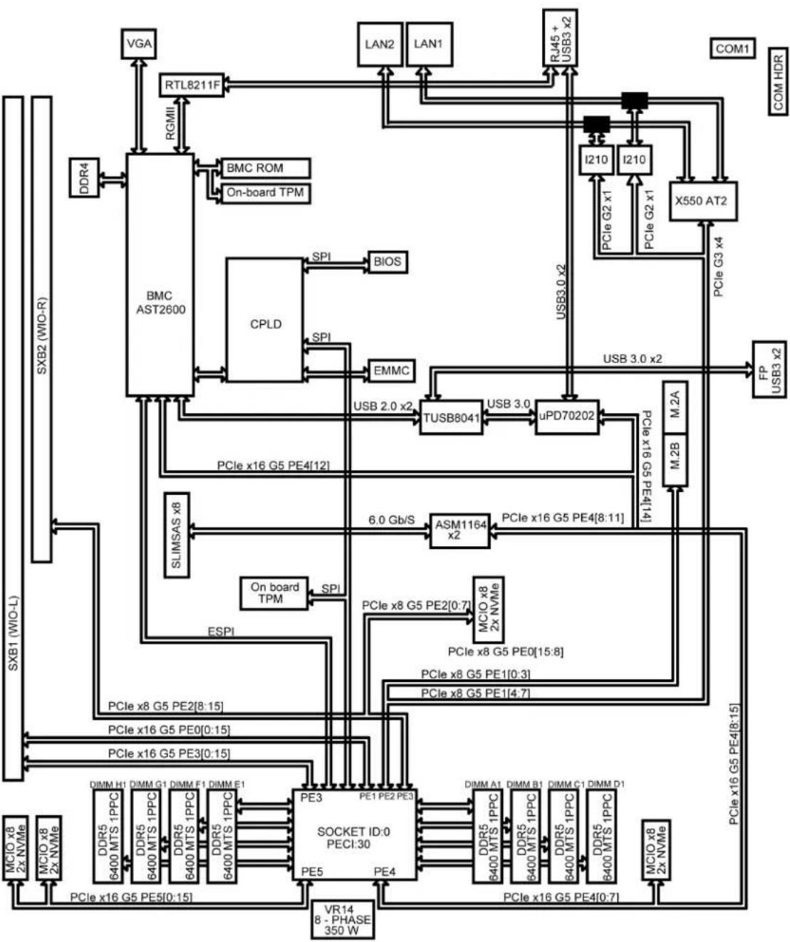
System Block Diagram
flowchart
graph TD
    subgraph Component1
        VGA --> RTL8211F
        RTL8211F --> BMC_ROM
        BMC_ROM --> OnBoard_TPM
        OnBoard_TPM --> CPLD
        CPLD --> SPI
        SPI --> BIOS
        SPI --> EMMC
        EMMC --> USB2.0x2
        USB2.0x2 --> TUSB8041
        TUSB8041 --> USB3.0
        USB3.0 --> uPD70202
        uPD70202 --> USB3.0x2
        USB3.0x2 --> X550_AT2
        X550_AT2 --> COM1
        COM1 --> COM_HDR
    end

    subgraph Component2
        I210 --> PCleG2x1
        I210 --> PCleG2x1
        PCleG2x1 --> PCleG3x4
        PCleG3x4 --> FP_USB3x2
        FP_USB3x2 --> FP_USB3x2
        FP_USB3x2 --> M_2A
        M_2A --> M_2B
        M_2B --> M_2A
    end

    subgraph Component3
        SLIMSAS_x8 --> PCle_x16G5PE4["12"]
        SLIMSAS_x8 --> PCle_x16G5PE4["14"]
        SLIMSAS_x8 --> OnBoard_TPM
        OnBoard_TPM --> SPI
        SPI --> USB2.0x2
        USB2.0x2 --> TUSB8041
        TUSB8041 --> USB3.0
        USB3.0 --> uPD70202
        uPD70202 --> USB3.0x2
        USB3.0x2 --> x30x2
    end

    subgraph Component4
        SLIMSAS_x8 --> PCle_x16G5PE4["15"]
        SLIMSAS_x8 --> PCle_x16G5PE4["15"]
        SLIMSAS_x8 --> OnBoard_TPM
        OnBoard_TPM --> SPI
        SPI --> USB2.0x2
        USB2.0x2 --> TUSB8041
        TUSB8041 --> USB3.0
        USB3.0 --> uPD70202
        uPD70202 --> USB3.0x2
    end

    subgraph Component5
        SLIMSAS_x8 --> PCle_x16G5PE4["15"]
        SLIMSAS_x8 --> PCle_x16G5PE4["15"]
        SLIMSAS_x8 --> OnBoard_TPM
        OnBoard_TPM --> SPI
        SPI --> USB2.0x2
        USB2.0x2 --> TUSB8041
        TUSB8041 --> USB3.0
    end

    subgraph Component6
        SLIMSAS_x8 --> PCle_x16G5PE4["15"]
        SLIMSAS_x8 --> PCle_x16G5PE4["15"]
        SLIMSAS_x8 --> OnBoard_TPM
        OnBoard_TPM --> SPI
        SPI --> USB2.0x2
        USB2.0x2 --> TUSB8041
        TUSB8041 --> USB3.0
                PCle_x16G5PE4["15"]
    end

    subgraph Component7
        SLIMSAS_x8 --> PCle_x16G5PE4["15"]
        SLIMSAS_x8 --> PCle_x16G5PE4["15"]
        SLIMSAS_x8 --> OnBoard_TPM
        OnBoard_TPM --> SPI
        SPI --> USB2.0x2
        USB2.0x2 --> TUSB8041
        TUSB8041 --> USB3.0
                    PCle_x16G5PE4["15"]
    end

    subgraph Component8
        SLIMSAS_x8 --> PCle_x16G5PE4["15"]
        SLIMSAS_x8 --> PCle_x16G5PE4["15"]
        SLIMSAS_x8 --> OnBoard_TPM
        OnBoard_TPM --> SPI
        SPI --> USB2.0x2
        USB2.0x2 --> TUSB8041
        TUSB8041 --> USB3.0
            PCle_x16G5PE4["15"]
    end

    subgraph Component9
        SLIMSAS_x8 --> PCle_x16G5PE4["15"]
        SLIMSAS_x8 --> PCle_x16G5PE4["15"]
        SLIMSAS_x8 --> OnBoard_TPM
        OnBoard_TPM --> SPI
        SPI --> USB2.0x2
        USB2.0x2 --> TUSB8041
        TUSB8041 --> USB3.0
          PCle_x16G5PE4["15"]
    end

    subgraph Component10
        SLIMSAS_x8 --> PCle_x16G5PE4["15"]
        SLIMSAS_x8 --> PCle_x16G5PE4["15"]
        SLIMSAS_x8 --> OnBoard_TPM
        OnBoard_TPM --> SPI
        SPI --> USB2.0x2
        USB2.0x2 --> TUSB8041
        TUSB8041 --> USB3.0
              PCle_x16G5PE4["15"]
    end

    subgraph Component11
        SLIMSAS_x8 --> PCle_x16G5PE4["15"]
        SLIMSAS_x8 --> PCle_x16G5PE4["15"]
        SLIMSAS_x8 --> OnBoard_TPM
        OnBoard_TPM --> SPI
        SPI --> USB2.0x2
        USB2.0x2 --> TUSB8041
        TUSB8041 --> USB3.0
                  PCle_x16G5PE4["15"]
    end

    subgraph Component12
        SLIMSAS_x8 --> PCle_x16G5PE4["15"]
        SLIMSAS_x8 --> PCle_x16G5PE4["15"]
        SLIMSAS_x8 --> OnBoard_TPM
        OnBoard_TPM --> SPI
        SPI --> USB2.0x2
        USB2.0x2 --> TUSB8041
        TUSB8041 --> USB3.0
                        PCle_x16G5PE4["15"]
    end

    subgraph Component13
        SLIMSAS_x8 --> PCle_x16G5PE4["15"]
        SLIMSAS_x8 --> PCle_x16G5PE4["15"]
        SLIMSAS_x8 --> OnBoard_TPM
        OnBoard_TPM --> SPI
        SPI --> USB2.0x2
        USB2.0x2 --> TUSB8041
        TUSB8041 --> USB3.0
                          PCle_x16G5PE4["15"]
    end

    subgraph Component14
        SLIMSAS_x8 --> PCle_x16G5PE4["15"]
        SLIMSAS_x8 --> PCle_x16G5PE4["15"]
        SLIMSAS_x8 --> OnBoard_TPM
        OnBoard_TPM --> SPI
        SPI --> USB2.0x2
        USB2.0x2 --> TUSB8041
        TUSB8041 --> USB3.0
Figure 1-4. System Block Diagram
1.2 Platform Overview
Built upon the capability of the Intel® Xeon® 6700-series processor with E-cores, the X14SBW-F/-TF WIO motherboard provides system performance, power efficiency, and feature sets to address the needs of next-generation computer users.
The X14SBW-F/-TF motherboard utilizes Supermicro legendary WIO rich and flexible I/O configuration features dramatically increases system performance in smallest footprint for a multitude of server, networking and storage applications and supports the following features:
- One WIO PCIe 5.0 x8 right riser (in x16) slot, one WIO PCIe 5.0 x32 left riser slot, five PCIe 5.0 x8 PCIe 5.0 MCIO connectors, CXL 2.0
- BMC supports remote management, virtualization, Redfish, and the security package for enterprise platforms
- Single socket E2 (LGA 4710) supported, processor supports up to 350 W TDP
- Up to 1 TB ECC RDIMM DDR5 6400 MT/s with eight DIMM slots
- Dual LAN with 10G Base-T with Intel ^® X550 (X14SBW-TF)
• Intel Software Guard Extensions (SGX), Intel Trusted Domain Extensions (TDX) - Intel QuickAssist Technology (QAT), Intel Dynamic Load Balancer (DLB) 2.5, Intel Data Streaming Accelerator, Intel In-Memory Analytics Accelerator (IAA) 2.0
1.3 Special Features
Recovery from AC Power Loss
The Basic I/O System (BIOS) provides a setting that determines how the system will respond when AC power is lost and then restored to the system. You can choose for the system to remain powered off (in which case you must press the power switch to turn it back on), or for it to automatically return to the power-on state. See Advanced Setup Configurations under "UEFI BIOS" on page 92 for this setting. The default setting is Last State.
1.4 System Health Monitoring
Onboard Voltage Monitors
An onboard voltage monitor will continuously scan the voltages of the onboard chipset, memory, processor, and battery. Once a voltage becomes unstable, a warning is given or an error message is sent to the screen. You can adjust the voltage thresholds to define the sensitivity of the voltage monitor. Real time voltage levels are displayed in IPMI.
Fan Status Monitor with Firmware Control
The system health monitor embedded in the BMC chip can check the RPM status of the cooling fans. The processor and chassis fans are controlled via IPMI.
Environmental Temperature Control
System Health sensors in the BMC monitor the temperatures and voltage settings of onboard processors and the system in real time via the IPMI interface. Whenever the temperature of the processor or the system exceeds a user-defined threshold, system/processor cooling fans will be turned on to prevent the processor or the system from overheating.
Note: To avoid possible system overheating, be sure to provide adequate airflow to your system.
1.5 ACPI Features
ACPI stands for Advanced Configuration and Power Interface. The ACPI specification defines a flexible and abstract hardware interface that provides a standard way to integrate power management features throughout a computer system, including its hardware, operating system and application software. This enables the system to automatically turn on and off peripherals such as network cards, hard disk drives, and printers.
In addition to enabling operating system-directed power management, ACPI also provides a generic system event mechanism for Plug and Play, an operating system-independent interface for configuration control. ACPI leverages the Plug and Play BIOS data structures while providing a processor architecture-independent implementation that is compatible with Windows Server 2022.
Chapter 2:
Component Installation
This chapter provides instructions on installing and replacing main system components for the X14SBW-F/-TF motherboard. To prevent compatibility issues, only use components that match the specifications and/or part numbers given.
Installation or replacement of most components require that power first be removed from the system. Follow the procedures given in each section.
2.1 Static-Sensitive Devices 28
Precautions 28
Unpacking 28
2.2 Motherboard Installation 29
Tools Needed 29.
Installing the Motherboard 29.
2.3 Processor and Heatsink Installation 32
LGA 4710 Socket E2 Processors 32
Overview of the Processor Carrier Assembly 33
Overview of the Processor Socket 34
Overview of the Processor Heatsink Module 35.
Creating the Processor Carrier Assembly .36
Assembling the Processor Heatsink Module 39
Preparing the Processor Socket for Installation 42
Preparing to Install the PHM into the Processor Socket 43
Installing the Processor Heatsink Module 45
Removing the Processor Heatsink Module 47
2.4 Memory Support and Installation 51
Memory Support 51
General Guidelines for Optimizing Memory Performance 53
DIMM Installation 53
DIMM Removal 56
2.5 Battery Removal and Installation 57
Battery Removal 57
Proper Battery Disposal 57.
Battery Installation 57.
2.6 Connections, Jumpers, and LEDs 59.
Power Supply and Power Connections 59
Headers and Connections 60.
Front Control Panel Header 66
I/O Ports 73
Jumper Settings 77.
LED Indicators 80.
2.1 Static-Sensitive Devices
Electrostatic Discharge (ESD) can damage electronic components. To avoid damaging your motherboard, it is important to handle it very carefully. The following measures are generally sufficient to protect your equipment from ESD.
Precautions
- Use a grounded wrist strap designed to prevent static discharge.
- Touch a grounded metal object before removing the board from the antistatic bag.
- Handle the motherboard by its edges only. Do not touch its components, peripheral chips, memory modules, or gold contacts.
- When handling chips or modules, avoid touching their pins.
- Put the motherboard and peripherals back into their antistatic bags when not in use.
- For grounding purposes, make sure that your computer chassis provides excellent conductivity between the power supply, the case, the mounting fasteners, and the motherboard.
- Use only the correct type of onboard CMOS battery. Do not install the onboard battery upside down to avoid possible explosion.
Unpacking
The motherboard is shipped in antistatic packaging to avoid static damage. When unpacking the motherboard, make sure that the person handling it is static protected.
2.2 Motherboard Installation
All motherboards have standard mounting holes to fit different types of chassis. Make sure that the locations of all the mounting holes for both the motherboard and the chassis match.
Although a chassis may have both plastic and metal mounting fasteners, metal ones are highly recommended because they ground the motherboard to the chassis. Make sure that the metal standoffs click in or are screwed in tightly.
Tools Needed

natural_image
Technical line drawings of three different screw and nut components (no text or symbols)Figure 2-1. Torque Driver (1), Phillips Screws (10), Standoffs (10, only if needed)
Notes:
- To avoid damaging the motherboard and its components, do not use a force greater than 8 lbf-in on each mounting screw during motherboard installation.
- Some components are very close to the mounting holes. Take precautionary measures to avoid damaging these components when installing the motherboard to the chassis.
Installing the Motherboard
- Install the I/O shield into the back of the chassis, if applicable.
Note: Images displayed are for illustration only. The components installed in your system may or may not look exactly the same as the graphics shown in the manual.

natural_image
Line drawing of a device with a fan, control panel, and monitor (no text or symbols)Figure 2-2. Install the I/O Shield
- Locate the mounting holes on the motherboard. See Motherboard Installation for the location.
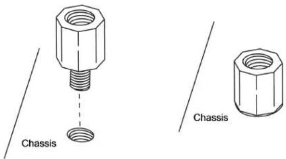
Figure 2-3. Locate the Mounting Holes
- Locate the matching mounting holes on the chassis. Align the mounting holes on the motherboard against the mounting holes on the chassis.

Figure 2-4. Align the Mounting Holes
- Install standoffs in the chassis as needed.
- Install the motherboard into the chassis carefully to avoid damaging other motherboard components.
-
Insert pan head #6 screws into the mounting holes on the motherboard and the matching mounting holes on the chassis.
-
Make sure that the motherboard is securely placed in the chassis.
2.3 Processor and Heatsink Installation
This section provides procedures to install the processor(s) and heatsink(s).
Notes:
- Take industry standard precautions to avoid ESD damage. For details, see "Static-Sensitive Devices" on page 28.
- Before starting, make sure that the plastic socket cap is in place and none of the socket pins are bent. If any damage is noted, contact your retailer.
- Do not connect the system power cord before the processor and heatsink installation is complete.
- When handling the processor, avoid touching or placing direct pressure on the LGA lands (gold contacts). Improper installation or socket misalignment can cause serious damage to the processor or processor socket.
• Install the processor in the socket and the motherboard into the chassis before installing the heatsink. - When buying a processor separately, use only a Supermicro certified heatsink.
• Refer to the Supermicro website for the most recent processor support. - Thermal grease is pre-applied on a new heatsink. No additional thermal grease is needed.
LGA 4710 Socket E2 Processors
Processor Top View

natural_image
Two 3D CAD renderings of a rectangular electronic component with mounting holes and internal channels (no text or symbols visible)Figure 2-5. Processor (SP XCC left, SP HCC/LCC right)
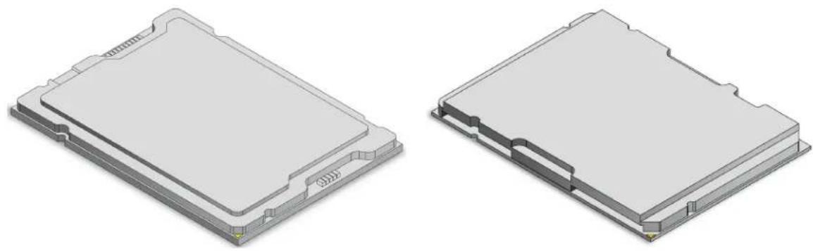
Note: The motherboard supports three processor SKUs: SP XCC, SP HCC, and SP LCC. Each SKU supports a specific carrier; the SP XCC processor supports Carrier E2A while SP HCC and SP LCC support Carrier E2B. Make sure the processors of the same SKU are on the motherboard.
Overview of the Processor Carrier Assembly
The processor carrier assembly contains the processors and processor carriers.
Processor
natural_image
Two 3D CAD renderings of a rectangular electronic component with mounting holes and internal channels (no text or symbols)Figure 2-6. Processor (SP XCC left, SP HCC/LCC right)
Processor Carriers

natural_image
Two technical line drawings of a mechanical housing or enclosure with mounting holes and internal components, no text or symbols present.Figure 2-7. Carrier (SP XCC E2A left, SP HCC/LCC E2B right)

natural_image
Pure architectural floor plan lines without any text, numbers, or symbols
natural_image
Pure technical diagram of a mechanical component with no text, numbers, or symbolsFigure 2-8. Carrier Top View (SP XCC E2A left, SP HCC/LCC E2B right)

natural_image
Architectural floor plan of a building with symmetrical staircases and central balcony (no text or labels)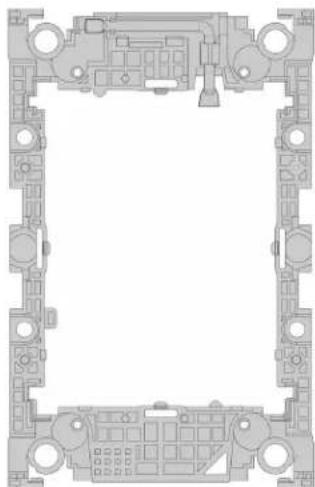
natural_image
Architectural floor plan of a building showing front and top views with room labels (no text or symbols)Figure 2-9. Carrier Bottom View (SP XCC E2A left, SP HCC/LCC E2B right)
Overview of the Processor Socket
The processor socket is protected by a plastic protective cover.

natural_image
Technical line drawing of a mechanical assembly with two views (top and side), showing internal components and mounting holes (no text or symbols)Figure 2-10. Plastic Protective Cover and Processor Socket
Overview of the Processor Heatsink Module
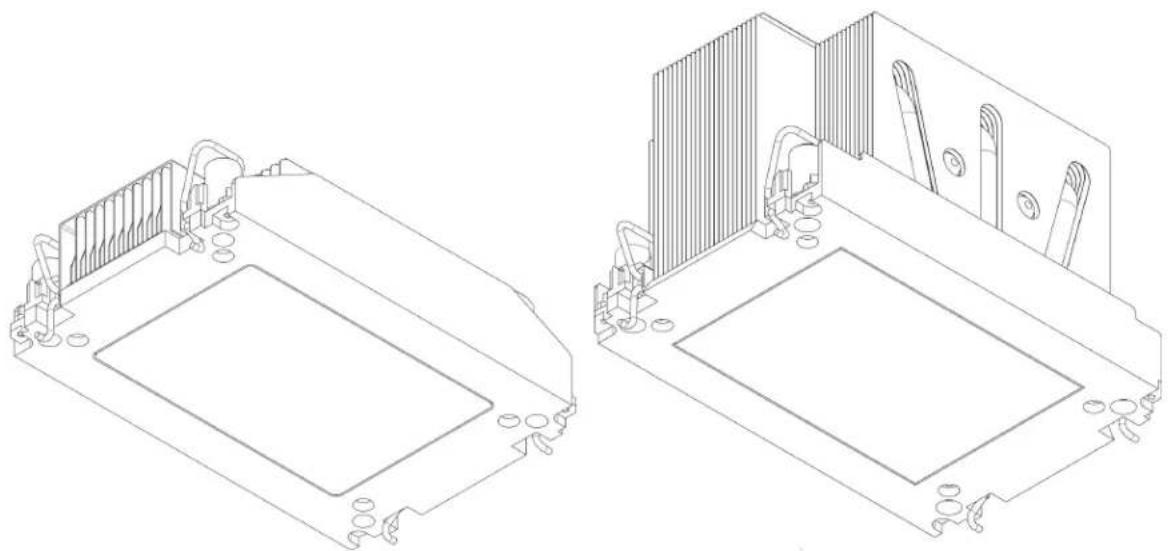
The Processor Heatsink Module (PHM) contains a heatsink, a processor carrier, and the processor.
natural_image
Technical line drawings of two electronic components with mounting brackets and internal structures (no text or symbols)Figure 2-11. Heatsink (1U left, 2U right)

natural_image
Technical line drawings of two 3D mechanical components with internal circuitry and mounting brackets (no text or symbols)Figure 2-12. Carrier (SP XCC E2A left, SP HCC/LCC E2B right)

natural_image
Two technical diagrams showing a grid-patterned panel with internal structural lines, no text or symbols present.Figure 2-13. Processor (SP XCC E2A left, SP HCC/LCC E2B right)
Creating the Processor Carrier Assembly
To install a processor into the processor carrier, follow the steps below:
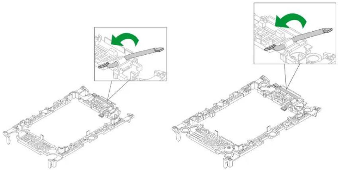
- Before installation, make sure the lever on the processor carrier is pressed down as shown below.
natural_image
Technical illustration of a mechanical assembly with two views showing tool positioning and assembly steps (no text or symbols)Figure 2-14. Carrier Lever (SP XCC left, SP HCC/LCC right)
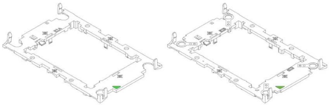
- Hold the processor with the LGA lands (gold contacts) facing up. Locate the small, gold triangle in the corner of the processor and the corresponding hollowed triangle on the processor carrier. These triangles indicate pin 1.

natural_image
Technical line drawings of two 3D electronic component modules (no text or symbols)Figure 2-15. Processor (SP XCC E2A left, SP HCC/LCC E2B right)
natural_image
Two technical line drawings of a mechanical housing or enclosure with mounting holes and internal components (no text or symbols)Figure 2-16. Carrier (SP XCC E2A left, SP HCC/LCC E2B right)
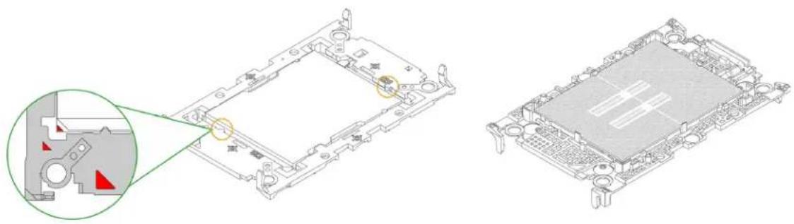
- Use the triangles as a guide to carefully align and place one end of the processor into the latch marked A, and place the other end of processor into the latch marked B as shown below.

Figure 2-17. Keys and Latches Locations (SP XCC E2A left, SP HCC/LCC E2B right)
- Examine all corners to ensure that the processor is firmly attached to the carrier.

Figure 2-18. SP XCC E2A Keys and Latches
natural_image
Technical diagram of a mechanical assembly with a magnified inset showing internal components (no text or symbols)Figure 2-19. SP HCC/LCC E2B Keys and Latches Together

natural_image
Two technical line drawings of a computer motherboard with visible components and mounting holes (no text or symbols)Figure 2-20. Carrier Assembly Complete (SP XCC E2A left, SP HCC/LCC E2B right)
Assembling the Processor Heatsink Module
After creating the processor carrier assembly for the processor, mount it onto the heatsink to create the processor heatsink module (PHM):
- Note the label on top of the heatsink, which marks the airflow direction. Turn the heatsink over and orient the heatsink so the airflow arrow is pointing towards the triangle on the processor.
- If this is a new heatsink, the thermal grease has been pre-applied. Otherwise, apply the proper amount of thermal grease.
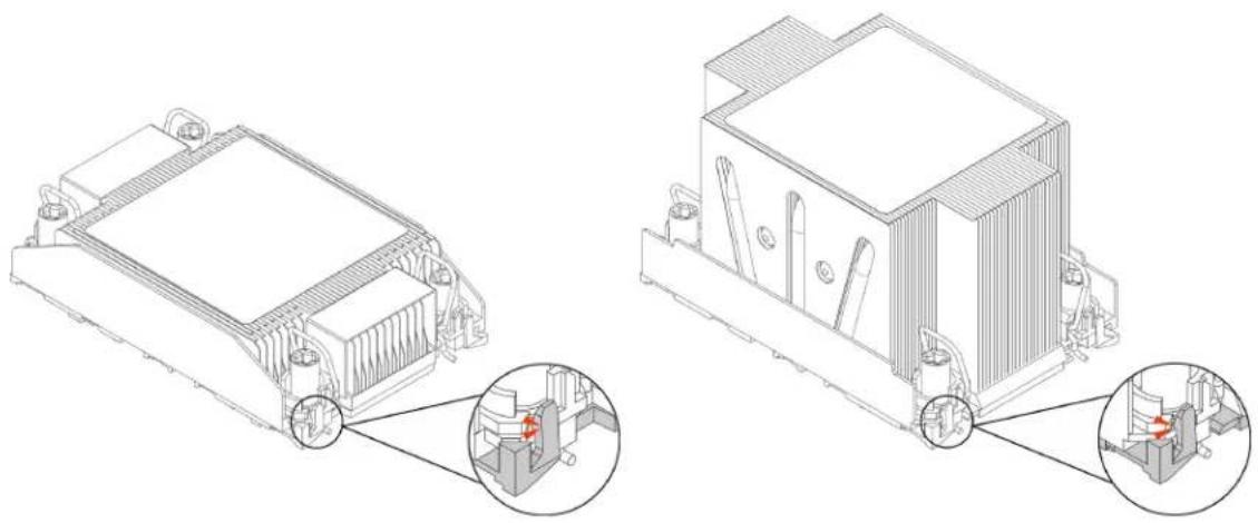
- Hold the processor carrier assembly so the processor's gold contacts are facing up, then align the holes of the processor carrier assembly with the holes on the heatsink. Press the processor carrier assembly down until it snaps into place. The plastic clips of the processor carrier assembly will lock at the four corners.


Figure 2-21. Carrier with 1U Heatsink (SP XCC left, SP HCC/LCC right)


Figure 2-22. Carrier with 2U Heatsink (SP XCC left, SP HCC/LCC right)
natural_image
Technical line drawing of a mechanical component with two views: top shows internal structure, bottom shows close-up of internal components (no text or symbols)Figure 2-23. PHM Plastic Clips Locked (1U left, 2U right)
- Examine all corners to ensure that the plastic clips on the processor carrier assembly are firmly attached to the heatsink.

natural_image
Technical line drawings of an electronic circuit board with internal components (no text or symbols)Figure 2-24. 1U PHM Completed (SP XCC left, SP HCC/LCC right)

natural_image
Isometric technical drawing of a computer motherboard with cooling fins and heatsink (no text or symbols)
natural_image
Technical line drawing of a computer motherboard with cooling fins and heatsink (no text or symbols)Figure 2-25. 2U PHM Completed (SP XCC left, SP HCC/LCC right)
Preparing the Processor Socket for Installation
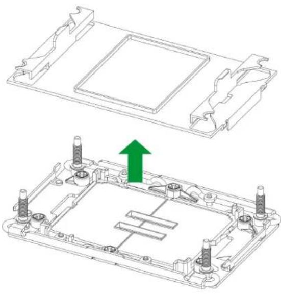
This motherboard comes with a plastic protective cover installed on the processor socket. Remove it from the socket to install the Processor Heatsink Module (PHM). Gently pull up one corner of the plastic protective cover to remove it.
- Press the tabs inward.

natural_image
Technical line drawing of a rectangular electronic component with mounting holes and green arrows indicating directional arrows (no text or symbols)Figure 2-26. Processor Socket with Plastic Protective Cover
- Pull up the protective cover from the socket.
natural_image
Technical line drawing of a mechanical assembly with mounting holes and a green upward arrow indicating a component (no text or symbols present)Figure 2-27. Plastic Protective Cover Removed
Note: Do not touch or bend the socket pins.
Preparing to Install the PHM into the Processor Socket
After assembling the Processor Heatsink Module (PHM), you are ready to install it into the processor socket. To ensure the proper installation, follow the procedures below:
- Locate four threaded fasteners (marked a, b, c, and d) on the processor socket.

a, b, c, d: Threaded Fasteners
Figure 2-28. Threaded Fasteners
- Locate four PEEK nuts (marked A, B, C, and D) and four rotating wires (marked 1, 2, 3, and 4) on the heatsink.
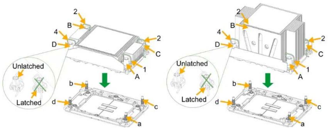
Figure 2-29. PEEK Nuts and Rotating Wires (1U left, 2U right)
- Check the rotating wires (marked 1, 2, 3, and 4) to make sure that they are at unlatched positions before installing the PHM into the processor socket.
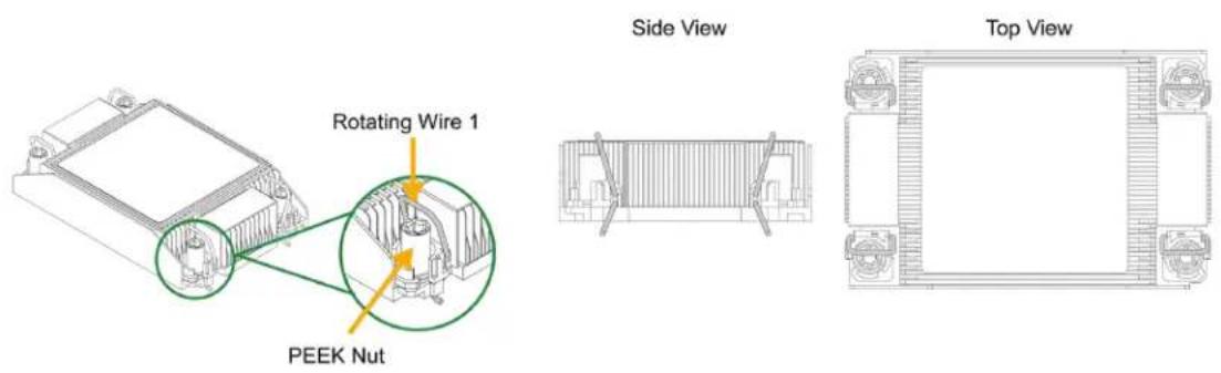
Figure 2-30. 1U Unlatched Positions

Figure 2-31. 2U Unlatched Positions
Installing the Processor Heatsink Module
- Align pin 1 of the PHM with the printed triangle on the processor socket.
- Make sure all four PEEK nuts of the heatsink (marked A, B, C, and D) are aligned with the threaded fasteners (marked a, b, c, and d), then gently place the heatsink on top of the processor socket.
A, B, C, D:
PEEK Nut on the Heatsink

a, b, c, d:
Threaded Fastener on the processor socket
A, B, C, D:
PEEK Nut on the Heatsink

a, b, c, d:
Threaded Fastener on the processor socket
Figure 2-32. Align the Heatsink with the Socket (1U left, 2U right)
- Press all four rotating wires outwards and make sure that the heatsink is securely latched into the processor socket.

natural_image
Technical line drawings of two electronic components with green arrows indicating rotation or assembly (no text or symbols present)Figure 2-33. Latch the PHM (1U left, 2U right)
- With a T30 bit torque driver set to a force of 8.0 in-lbf (0.904 N-m), gradually tighten the four screws to ensure even pressure. You can start with any screw, but make sure to tighten the screws in a diagonal pattern.
Important: Do not use a force greater than 8.0 in-lbf (0.904 N-m). Exceeding this force may over-torque the screw, causing damage to the processor, heatsink, and screw.
- Examine all corners to ensure that the PHM is firmly attached to the socket.

Figure 2-34. Install the PHM with a Torque Driver (1U left, 2U right)
Removing the Processor Heatsink Module
Before removing the processor heatsink module (PHM) from the motherboard, shut down the system and then unplug the AC power cord from all power supplies.
Then follow the steps below:
- Use a screwdriver to loosen the four screws. You can start with any screw, but make sure to loosen the screws in a diagonal pattern.

Figure 2-35. Loosen the Screws (1U left, 2U right)
- Press the four rotating wires inwards to unlatch the PHM from the socket.

natural_image
Technical line drawing of two mechanical components with green arrows indicating rotation or assembly (no text or symbols)Figure 2-36. Unlatch the PHM (1U left, 2U right)
- Gently lift the PHM upwards to remove it from the socket.

natural_image
Technical line drawings of a heat exchanger housing with green arrows indicating assembly or component movement (no text or symbols present)Figure 2-37. Remove the PHM from the Socket (1U left, 2U right)
- To remove the processor from the heatsink, gently lift the lever from the processor carrier.

natural_image
Two technical line drawings of an electronic device chassis with internal components and green arrows indicating rotation (no text or symbols present)Figure 2-38. Carrier with 1U Heatsink (SP XCC left, SP HCC/LCC right)

natural_image
Technical line drawings of a battery module with internal components and green arrows indicating rotation (no text or symbols)Figure 2-39. Carrier with 2U Heatsink (SP XCC left, SP HCC/LCC right)
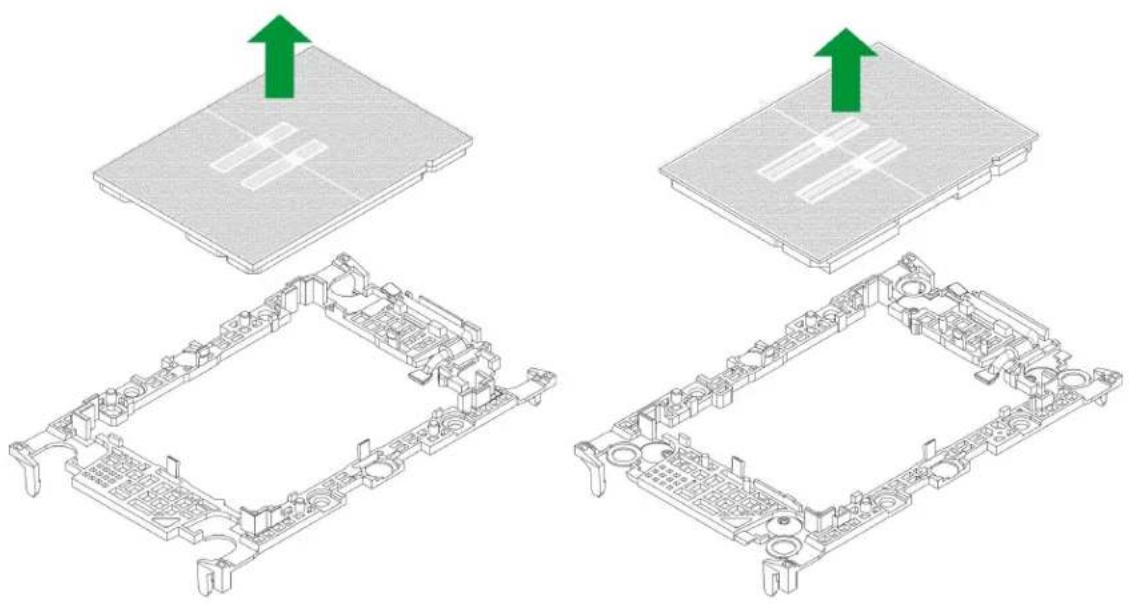
- To remove the processor, move the lever to its unlocked position and gently remove the processor.
natural_image
Technical illustration of a computer motherboard with green arrows indicating upward motion (no text or symbols present)Figure 2-40. Processor Removal (SP XCC left, SP HCC/LCC right)
2.4 Memory Support and Installation

Warning! Exercise extreme care when installing or removing memory modules to prevent any damage.

Note: Check the Supermicro website for recommended memory modules.
Memory Support
The X14SBW-F/-TF motherboard supports up to 1 TB of RDIMM ECC memory with speeds of up to 6400 MT/s (1DPC) in eight memory slots.
| DDR5-6400 Memory Support for the Intel® Xeon® 6700-series processors with E-cores | |||||
| Type | Ranks Per DIMM, Data Width (Stack) | DIMM Capacity (GB) | Speed (MT/s); Voltage (V); Slots per Channel (SPC) and DIMMs per Channel (DPC) | ||
| DRAM Density | |||||
| 16 Gb 24 | Gb 32 Gb 1DPC/2SPC | ||||
| 1DPC 1DPC 1DPC 1.1 V | |||||
| RDIMM | 1Rx4 32 GB - | 6400, 6000, 5600, 5200, 4800 (DDR5-6400 rated RDIMMs only) | |||
| 2Rx8 32 GB - | |||||
| 2Rx4 64 GB 96 GB - | |||||
| 2Rx4 - - 128 GB | |||||
| CXL Memory Configuration Support for the Intel® Xeon® 6700-series processors with E-cores | ||||||||
| Native DDR5 Memory Per Socket CXL Memory Per Socket | ||||||||
| Slot 0DIMMRanks | Slot 0DIMMCapacity(GB) | DIMMType | DRAMDensity(Gb) | CXLMemoryChannels | CXLMemoryType | CXLCapacityPerDevice/Module | CXLInterleave | CXLMode |
| 2Rx4 64 | 10x4 16 2+2 DDR5 x8 64 GB | 1x4*, 2x2, 4x1 | 1LM+Vol | |||||
| 2Rx4 64 | 10x4 16 1+1 DDR5 x16 128 GB 1x2*, 2x1 1LM+Vol | |||||||
| 1Rx4 32 | 10x4 16 2 DDR5 x8 128 GB 1x2* | Intel Flat Memory Mode | ||||||
Notes:
- The items with an asterisk (*) are the default settings in BIOS.
- The Intel ^® Xeon ^® 6700-series processors with E-cores CXL memory configurations are 1DPC ('Slot 0') only for native DDR5.
- CXL Memory Channel: number of devices per root port, with root ports separated by "+," e.g. 2+2+2+2 = four root ports populated with two devices per root port
- CXL Interleave: sets x ways, e.g. 2x4 = One set of two modules, interleaved four-way
- CXL Modes:
- 1LM + Vol = DDR5 ('1LM') and (volatile) CXL memory visible to SW as separate tiers, separately interleaved
- Hetero x12 = DDR5 and (volatile) CXL memory interleaved together in one 12-way set
- Flat Memory Mode = HW manages data movement between DDR5 and CXL memory, total capacity visible to SW
| Intel® Xeon® 6700-series processors with E-cores DDR5 Memory Population Table(1 Processor and 8 DIMMs Installed, 1DPC) | |
| DIMM Counts Memory Population Sequence (1DPC) | |
| 1 Processor and 1 DIMM | DIMMA1 |
| 1 Processor and 4 DIMMs | DIMMA1/DIMMC1/DIMME1/DIMMG1DIMMB1/DIMMD1/DIMMH1/DIMMF1 |
| 1 Processor and 8 DIMMs | DIMMA1/DIMMB1/DIMMC1/DIMMD1/DIMME1/DIMMF1/DIMMG1/DIMMH1 |
| Intel® Xeon® 6700-series processors with E-cores DDR5 Memory Population Table(1 Processor and 16 DIMMs Installed, 2DPC) | |
| DIMM Counts Memory Population Sequence (2DPC) | |
| 1 Processor and 1 DIMM | DIMMA1 |
| 1 Processor and 4 DIMMs | DIMMA1/DIMMC1/DIMME1/DIMMG1DIMMB1/DIMMD1/DIMMF1/DIMMH1 |
| 1 Processor and 8 DIMMs | DIMMA1/DIMMA2/DIMMC1/DIMMC2/DIMME1/DIMME2/DIMMG1/DIMMG2DIMMB1/DIMMB2/DIMMD1/DIMMD2/DIMMF1/DIMMF2/DIMMH1/DIMMH2DIMMA1/DIMMB1/DIMMC1/DIMMD1/DIMME1/DIMMF1/DIMMG1/DIMMH1 |
| 1 Processor and 16 DIMMs | DIMMA1/DIMMA2/DIMMB1/DIMMB2/DIMMC1/DIMMC2/DIMMD1/DIMMD2/DIMME1/DIMME2/DIMMF1/DIMMF2/DIMMG1/DIMMG2/DIMMH1/DIMMH2 |
General Guidelines for Optimizing Memory Performance
- It is recommended to use DDR5 memory of the same type, size, and speed.
- Mixed DIMM speeds can be installed. However, all DIMMs will run at the speed of the slowest DIMM.
DIMM Installation

Warning! Do not use excessive force when pressing the release tabs on the ends of the DIMM socket to avoid causing any damage to the memory module or the DIMM socket. Handle memory modules with care. Carefully follow all the instructions given in "Static-Sensitive Devices" on page 28 to avoid ESD-related damages done to your memory modules or components.

- Insert the desired number of DIMMs into the memory slots based on the recommended DIMM population table earlier in this section.
- Push the release tabs outwards on both ends of the DIMM slot to unlock it.

natural_image
Pure mechanical component diagram without any text, numbers, or symbolsFigure 2-41. Unlock the DIMM Slot
- Align the key of the DIMM with the receptive point on the memory slot.

natural_image
Diagram of a computer RAM module with a highlighted slot and arrow indicating compression or disassembly (no text or symbols present)Figure 2-42. Align the DIMM Slot with the Receptive Point
- Align the notches on both ends of the module against the receptive points on the ends of the slot.

Figure 2-43. Align the Notches
- Press both ends of the module straight down into the slot until the module snaps into place.
- Press the release tabs to the lock positions to secure the DIMM into the slot.

Figure 2-44. Press Both Ends
For a detailed diagram of the X14SBW-F/-TF motherboard, see the layout under "Quick Reference" on page 12.
DIMM Removal

Warning! Do not use excessive force when pressing the release tabs on the ends of the DIMM socket to avoid causing any damage to the memory module or the DIMM socket. Handle memory modules with care. Carefully follow all the instructions given in "Static-Sensitive Devices" on page 28 to avoid ESD-related damages done to your memory modules or components.

Press both release tabs on the ends of the DIMM socket to unlock it. Once the DIMM is loosened, remove it from the memory slot.

natural_image
Diagram of a computer RAM module with two green arrows indicating rotation or assembly (no text or symbols present)For a detailed diagram of the X14SBW-F/-TF motherboard, see the layout under "Quick Reference" on page 12.
2.5 Battery Removal and Installation
Battery Removal
To remove the onboard battery, follow the steps below:
- Power off your system and unplug your power cable.
- Locate the onboard battery as shown below.
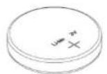
- Using a tool such as a pen or a small screwdriver, push the battery lock outwards to unlock it. Once unlocked, the battery will pop out from the holder.
- Remove the battery.
Proper Battery Disposal

Warning! Handle used batteries carefully. Do not damage the battery in any way; a damaged battery may release hazardous materials into the environment. Do not discard a used battery in the garbage or a public landfill. Comply with the regulations set up by your local hazardous waste management agency to dispose of your used battery properly.

Battery Installation
To install an onboard battery, follow steps 1 and 2 above and continue below:

Warning! When replacing a battery, be sure to only replace it with the same type.

- Identify the battery's polarity. The positive (+) side should be facing up.
- Insert the battery into the battery holder and push it down until you hear a click to ensure that the battery is securely locked.
LITHIUM BATTERY

OR
LITHIUM BATTERY


BATTERY HOLDER

BATTERY HOLDER

2.6 Connections, Jumpers, and LEDs
Refer to the following sections for information about connections, jumpers, and LEDs for the X14SBW-F/-TF motherboard.
Power Supply and Power Connections
For information about the power connections of the X14SBW-F/-TF motherboard, refer to the following content.
Power Supply
As with all computer products, a stable power source is necessary for proper and reliable operation. It is even more important for processors that have high CPU clock rates where noisy power transmission is present.
Power Connectors
Power connectors are located at JPWR1, JPWR2, and JPWR3 on the X14SBW-F/-TF motherboard. JPWR3 is the 24-pin power connector for ATX power source. JPWR1 (8-pin) and JPWR2 (4-pin) are the 12 V DC power connectors that provide power to the CPU in conjunction with JPWR3 or they can be used as the sole 12 V DC only power inputs when JPWR3 is not in use.
| ATX Power 24-pin ConnectionPin Definitions: 24 Total | |||
| Pin# Definition Pin# Definition | |||
| 13 +3.3 V | 1 +3.3 V | ||
| 14 | NoConnection | 2 +3.3 V | |
| 15 GND | 3 GND | ||
| 16 PS_ON | 4 +5 V | ||
| 17 GND | 5 GND | ||
| 18 GND | 6 +5 V | ||
| 19 GND | 7 GND | ||
| 20 | Res (NoConnection) | 8 PWR_OK | |
| 21 +5 V | 9 5 VSB | ||
| 22 +5 V | 10 +12 V | ||
| 23 +5 V | 11 +12 V | ||
| 24 GND | 12 +3.3 V | ||
| 8-pin CPU PowerPin Definitions:Eight Total | |
| Pin# Definition | |
| 1-4 GND | |
| 5-8 | P12 V (12 VPower) |
| 4-pin CPU PowerPin Definitions: Four Total | |
| Pin# Definition | |
| 1-2 GND | |
| 3-4 | P12 V (12 VPower) |
Headers and Connections
For information about the headers of the X14SBW-F/-TF motherboard, refer to the following content.
Chassis Intrusion
A Chassis Intrusion header is located at JL1 on the X14SBW-F/-TF motherboard. Attach the appropriate cable from the chassis to inform you when the chassis is opened.
For a detailed diagram of the X14SBW-F/-TF motherboard, see the layout under "Quick Reference" on page 12.
| Chassis IntrusionPin Definitions: Two Total | |
| Pin# Definition | |
| 1 | Intrusion Input |
| 2 | GND |
External BMC I²C Header
A System Management Bus header for the BMC is located at JIPMB1 on the X14SBW-F/-TF motherboard. Connect the appropriate cable here to use the IPMB I²C connection on your system.
For a detailed diagram of the X14SBW-F/-TF motherboard, see the layout under "Quick Reference" on page 12.
Fan Headers
There are six 4-pin fan headers (FAN1–FAN6) on the X14SBW-F/-TF motherboard. All the 4-pin fan headers are backwards compatible with the traditional 3-pin fans. However, fan speed control is available for 4-pin fans only by Thermal Management via the IPMI 2.0 interface.
For a detailed diagram of the X14SBW-F/-TF motherboard, see the layout under "Quick Reference" on page 12.
| 4-pin Fan HeaderPin Definitions: Four Total | |
| Pin# Definition | |
| 1 GND (Black) | |
| 2 +12 V (Red) | |
| 3 Tachometer | |
| 4 PWM Control | |
Inlet Sensor Header
An inlet sensor header is located at JSEN1 on the X14SBW-F/-TF motherboard. The inlet temperature sensor represents the ambient air temperature entering the system. The equivalent temperature sensor retrievable by the onboard BMC is RT0.
For a detailed diagram of the X14SBW-F/-TF motherboard, see the layout under "Quick Reference" on page 12.
| Inlet Sensor HeaderPin Definitions: Four Total | |
| Pin# Definition | |
| 1 Data | |
| 2 GND | |
| 3 Clock | |
| 4 3V3 Stby | |
M.2 Slots
Two M.2 M-Key slots are located at JM2_1, JM2_2 on the X14SBW-F/-TF motherboard. M.2 was formerly known as Next Generation Form Factor (NGFF) and serves to replace mini PCIe. M.2 allows for a variety of card sizes, increased functionality, and spatial efficiency. The M.2 M-Key slots on the motherboard support PCIe 5.0 x2 devices in a 2280/22110 form factor.
For a detailed diagram of the X14SBW-F/-TF motherboard, see the layout under "Quick Reference" on page 12.
MCIO PCIe 5.0 x8 Connectors
Mini Cool Edge IO (MCIO) PCIe 5.0 x8 connectors are located at JNVME1-JNVME4 on the X14SBW-F/-TF motherboard.
For a detailed diagram of the X14SBW-F/-TF motherboard, see the layout under "Quick Reference" on page 12.
NC-SI Connection
Note: For detailed instructions on how to configure Network Interface Card (NIC) settings, refer to the Network Interface Card Configuration User's Guide posted on the web page under the link: https://www.supermicro.com/support/manuals.
For a detailed diagram of the X14SBW-F/-TF motherboard, see the layout under "Quick Reference" on page 12.
NVMe SMBus Headers
Two NVMe SMBus (I²C) headers are located at JNVI²C1 and JNVI²C2 on the X14SBW-F/-TF motherboard). They are used for PCIe SMBus clock and data connections, provides hot-plug support through a dedicated SMBus interface. This feature is only available for a Supermicro complete system with a Supermicro proprietary NVMe add-on card and a proper cable installed.
For a detailed diagram of the X14SBW-F/-TF motherboard, see the layout under "Quick Reference" on page 12.
| NVMe SMBus HeadersPin Definitions: Four Total | |
| Pin# Definition | |
| 1 Data | |
| 2 GND | |
| 3 Clock | |
| 4 +3.3 V | |
Power SMB (I²C) Header
The Power System Management Bus (I²C) connector (JPI²C1 on the X14SBW-F/- TF motherboard) monitors the power supply, fan, and system temperatures.
For a detailed diagram of the X14SBW-F/-TF motherboard, see the layout under "Quick Reference" on page 12.
| Power SMBus HeaderPin Definitions: Five Total | |
| Pin# Definition | |
| 1 Clock | |
| 2 Data | |
| 3 PMBUS_Alert | |
| 4 GND | |
| 5 +3.3 V | |
Standby Power
The Standby Power header is located at JSTBY1 on the motherboard. You must have a card with a Standby Power connector and a cable to use this feature.
For a detailed diagram of the X14SBW-F/-TF motherboard, see the layout under "Quick Reference" on page 12.
| Standby PowerPin Definitions: Three Total | |
| Pin# Definition | |
| 1 +5 V Standby | |
| 2 GND | |
| 3 No Connection | |
SATA 3.0 Ports (Slimline SAS)
SATA 3.0 ports are located at SATA0–7 on the X14SBW-F/-TF motherboard. The connections are supported by the chipset through SlimSAS connector that supports eight SATA3 devices or two PCIe 3.0 x4 devices.
TPM/Port 80 Header
The JTPM1 header on the X14SBW-F/-TF motherboard is used to connect a Trusted Platform Module (TPM)/Port 80, which is available from Supermicro (optional). A TPM/Port 80 connector is a security device that supports encryption and authentication in hard drives. It allows the motherboard to deny access if the TPM associated with the hard drive is not installed in the system. Go to the following link for more information on the TPM: https://www.supermicro.com/manuals/other/AOM-TPM-9670V_9670H_X12_H12.pdf.
For a detailed diagram of the X14SBW-F/-TF motherboard, see the layout under "Quick Reference" on page 12.
| Trusted Platform Module HeaderPin Definitions: 10 Total | |||
| Pin# Definition Pin# Definition | |||
| 1 +3.3 V 2 | SPI_CS# | ||
| 3 RESET# 4 SPI_MISO | |||
| 5 SPI_CL | K 6 Ground | ||
| 7 SPI_MOSI | 8 No Connection | ||
| 9 +1.8 V Stdby | 10 | SPI_IRQ# | |
VROC RAID Key Header
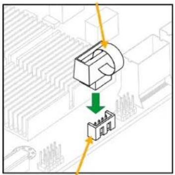
A VROC RAID Key header is located at JRK1 on the X14SBW-F/-TF motherboard. Install a VROC RAID key on JRK1 for NVMe RAID support as shown in the illustration below.
Note: For detailed instructions on how to configure VROC RAID settings, refer to the VROC RAID Configuration User's Guide posted on the web page under the link: https://www.supermicro.com/support/manuals.
For a detailed diagram of the X14SBW-F/-TF motherboard, see the layout under "Quick Reference" on page 12.
Note: Images displayed are for illustrative purposes only. The components installed in your system may or may not look exactly the same as the graphics shown in the manual.
| Intel VROC KeyPin Definitions: FourTotal | |
| Pin# Definition | |
| 1 GND | |
| 2 3.3 V Standby | |
| 3 GND | |
| 4 | CPU RAIDKey |
Front Control Panel Header
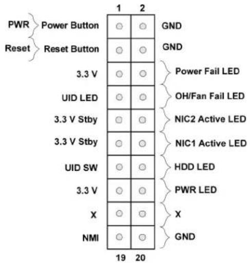
JF1 on the X14SBW-F/- TF motherboard contains header pins for various buttons and indicators that are normally located on a control panel at the front of the chassis. These connectors are designed specifically for use with Supermicro chassis. See the figure below for the descriptions of the front control panel buttons and LED indicators.
Power Button
The Power Button connection is located on pins 1 and 2 of JF1 on the X14SBW-F/-TF motherboard. Momentarily contacting both pins will power on/off the system. This button can also be configured to function as a suspend button (with a setting in the BIOS). To turn off the power when the system is in suspend mode, press the button for four seconds or longer.
For a detailed diagram of the X14SBW-F/-TF motherboard, see the layout under "Quick Reference" on page 12.
| Power ButtonPin Definitions (JF1) | |
| Pin# Definition | |
| 1 Signal | |
| 2 GND | |

Reset Button
The Reset Button connection is located on pins 3 and 4 of JF1 on the X14SBW-F/- TF motherboard. Attach it to a hardware reset switch on the computer case to reset the system.
For a detailed diagram of the X14SBW-F/-TF motherboard, see the layout under "Quick Reference" on page 12.
| Reset ButtonPin Definitions (JF1) | |
| Pin# Definition | |
| 3 Reset | |
| 4 GND | |

Power Fail LED
The Power Fail LED connection is located on pins 5 and 6 of JF1 on the X14SBW-F/-TF motherboard.
For a detailed diagram of the X14SBW-F/-TF motherboard, see the layout under "Quick Reference" on page 12.
| Power Fail LEDPin Definitions (JF1) | |
| Pin# Definition | |
| 5 3.3 V | |
| 6 PWR Supply Fail | |

Overheat/Fan Fail and UID LED
Connect an LED cable to pins 7 and 8 of the Front Control Panel to use the Overheat/Fan Fail LED connections. The LED on pin 8 provides warnings of overheat or fan failure.
For a detailed diagram of the X14SBW-F/-TF motherboard, see the layout under "Quick Reference" on page 12.
| OH/Fan Fail IndicatorStatusPin Definitions (JF1) | |
| State Definition | |
| Off Normal | |
| On Overheat | |
| Flashing Fan Fall | |
| OH/Fan Fail/UID LEDPin Definitions (JF1) | |
| Pin# Definition | |
| 7 UID LED (Blue) | |
| 8 | OH/FAN FailLED |

The Network Interface Controller (NIC) LED connection for LAN port 1 is located on pins 11 and 12 of JF1 on the X14SBW-F/-TF motherboard, and LAN port 2 is on pins 9 and 10. Attach the NIC LED cables here to display network activity.
For a detailed diagram of the X14SBW-F/-TF motherboard, see the layout under "Quick Reference" on page 12.
| LAN1/LAN2 LEDPin Definitions (JF1) | |
| Pin# Definition | |
| 9 VCC | |
| 10 NIC2 Link/Active LED | |
| 11 VCC | |
| 12 NIC1 Link/Active LED | |

HDD LED/UID Switch
The HDD LED connection is located on pins 13 and 14 of JF1 on the X14SBW-F/-TF motherboard. Attach a cable to pin 14 to show storage drive activity status. Attach a cable to pin 13 to use the UID button.
For a detailed diagram of the X14SBW-F/-TF motherboard, see the layout under "Quick Reference" on page 12.
| HDD LED/UID ButtonPin Definitions (JF1) | |
| Pin# Definition | |
| 13 3.3 V Stdbv/UID Button | |
| 14 HDD Activity |

Power LED
The Power LED connection is located on pins 15 and 16 of JF1 on the X14SBW-F/-TF motherboard.
For a detailed diagram of the X14SBW-F/-TF motherboard, see the layout under "Quick Reference" on page 12.
| Power LEDPin Definitions (JF1) | |
| Pin# Definition | |
| 15 3.3 V | |
| 16 PWR LED | |
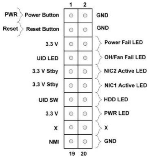
NMI Button
The non-maskable interrupt (NMI) button header is located on pins 19 and 20 of JF1 on the X14SBW-F/-TF motherboard.
For a detailed diagram of the X14SBW-F/-TF motherboard, see the layout under "Quick Reference" on page 12.
| NMI ButtonPin Definitions (JF1) | |
| Pin# Definition | |
| 19 Control | |
| 20 GND | |

I/O Ports

Figure 2-45. X14SBW-F/-TF I/O Ports
| I/O Ports | |||
| # Description # Description | iption | ||
| 1 COM1 5 LAN1 | |||
| 2 BMC_LAN 6 LAN2 | |||
| 3 USB0 (3.2 Gen 1) 7 VGA | |||
| 4 USB1 (3.2 Gen 1) 8 UID | Button | ||
COM Port
There is one COM port (COM1) on the I/O ports of the motherboard. The COM port provides serial communication support.
For a detailed diagram of the X14SBW-F/-TF motherboard, see the layout under "Quick Reference" on page 12.
| COM PortPin Definitions: 11 Total | |||
| Pin# Definition Pin# Definition | |||
| 1 SP_DCD0 6 SP_DSR0 | |||
| 2 SP_RXD0 7 SP_RTS0 | |||
| 3 SP_TXD0 8 SP_CTS0 | |||
| 4 SP_DTR0 9 SP_RIO | |||
| 5 GND 10 | GND | ||
| 11 | GND | ||
LAN Ports
The motherboard has dual 1 GbE LAN ports (i210, X14SBW-F) or dual 10 GbE LAN ports (X550, X14SBW-TF) located at the rear I/O ports of the X14SBW-F/-TF motherboard. The two 1 GbE and 10 GbE LAN ports accept RJ45 cables. In addition to the LAN ports, there is one dedicated BMC LAN port.
For a detailed diagram of the X14SBW-F/-TF motherboard, see the layout under "Quick Reference" on page 12.
| LAN PortsPin Definitions: 21 Total | |||
| Pin# Definition Pin# Definition | |||
| 1 TRD1P | 11 TRD4N | ||
| 2 TRD1N | 12 TRCT4 | ||
| 3 TRCT1 | 13 TRD5P | ||
| 4 TRD2P | 14 TRD5N | ||
| 5 TRD2N | 15 L1-GRE- | ||
| 6 TRCT2 | 16 L1-GRE+ | ||
| 7 TRD3P | 17 L2-YEL- | ||
| 8 TRD3N | 18 COMMON | ||
| 9 TRCT3 | 19 L2-GRE | ||
| 10 TRD4P | 20 CG1 | ||
| 21 CG2 | |||
| BMC LANPin Definitions: 19 Total | |||
| Pin# Definition Pin# | Definition | ||
| 29 | Link 1000 LED (Amber) | ||
| 20 | TD0+ | 30 | Link 100 LED (Green) |
| 21 | TD0- | 31 | Active LED (Yellow) |
| 22 | TD1+ | 32 | GND |
| 23 | TD1- | 33 | SGND |
| 24 | TD2+ | 34 | SGND |
| 25 | TD2- | 35 | SGND |
| 26 | TD3+ | 36 | SGND |
| 27 | TD3- | ||
| 28 | GND | ||
Unit Identifier Button
A Unit Identifier (UID) button and two LED Indicators are located on the motherboard. The UID button is located near the I/O ports of the X14SBW-F/-TF motherboard.
Note: After pushing and holding the UID button for 12 seconds, all BMC settings including username and password will revert back to the factory default. Only the network settings and FRU are retained.
For a detailed diagram of the X14SBW-F/-TF motherboard, see the layout under "Quick Reference" on page 12.
| Function User Input Behavior LED Activity | |||
| UID LED Indicator | Push Once Push Again | Turns on the UID LED Turns off the UID LED | UID LED turns solid blue UID LED turns off |
| BMC Reset | Push and hold for 6 seconds Push and hold for 12 seconds | BMC will do a cold boot BMC will reset to factory default | BMC Heartbeat LED turns solid green BMC Heartbeat LED turns solid green |
| UID ButtonPin Definitions: Four Total | |
| Pin# Definition | |
| 1 Button In | |
| 2 GND | |
| G1 GND | |
| G2 GND | |
| UID LEDPin Definitions:Four Total | |
| Color Status | |
| 1 Button In | |
| 2 GND | |
| G1 GND | |
| G2 GND | |
USB Ports
There are two USB 3.2 Gen 1 ports (USB0/1) located at the rear I/O ports f the X14SBW-F/-TF motherboard. There is also one USB 3.2 Gen 1 header (USB2/3) on the front panel.
For a detailed diagram of the X14SBW-F/-TF motherboard, see the layout under "Quick Reference" on page 12.
| USB0/1 (USB 3.2 Gen 1) PortPin Definitions: 18 Total | |||
| Pin# Definitions Pin# Definitions | |||
| 1 VBUS 10 VBUS | |||
| 2 D- 11 D- | |||
| 3 D+ 12 D+ | |||
| 4 GND 13 GND | |||
| 5 STDA_SSRX- 14 STDA_S SRX- | |||
| 6 STDA_SSRX+ 15 STDA_SSRX+ | |||
| 7 GND 16 GND | |||
| 8 STDA_SSTX- 17 STDA_S STX- | |||
| 9 STDA_SSTX+ 18 STDA_SSTX+ | |||
| USB 2/3 (USB 3.2 Gen 1) HeaderPin Definitions: 20 Total | |||
| Pin# Definitions Pin# Definitions | |||
| 1 VBUS 1 | IntA_P2_D+ | ||
| 2 | IntA_P1_SSRX- | 12 IntA_P2_D- | |
| 3 | IntA_P1_SSRX+ | 13 GND | |
| 4 GND 14 | IntA_P2_SSTX+ | ||
| 5 | IntA_P1_SSTX- | 15 | IntA_P2_SSTX- |
| 6 | IntA_P1_SSTX+ | 16 GND | |
| 7 GND 17 | IntA_P2_SSRX+ | ||
| 8 IntA_P1_D- 18 | IntA_P2_SSRX- | ||
| 9 IntA_P1_D+ 19 VBUS | |||
| 10 GND 20 No Connection | |||
VGA Port
A video (VGA) port is located on the I/O ports of the motherboard. The VGA port provides analog interface support between the computer and the video displays.
For a detailed diagram of the X14SBW-F/-TF motherboard, see the layout under "Quick Reference" on page 12.
Jumper Settings
To modify the operation of the motherboard, jumpers can be used to choose between optional settings. Jumpers create shorts between two pins to change the function of the connector. Pin 1 is identified with a square solder pad on the printed circuit board. See the diagram below for an example of jumping pins 1 and 2. Refer to the motherboard layout page for jumper locations.
Note: On two-pin jumpers, "Closed" means the jumper is on and "Open" means the jumper is off the pins.

CMOS Clear
JBT1 on the X14SBW-F/-TF motherboard is used to clear CMOS, which will also clear any passwords. Instead of pins, this jumper consists of contact pads to prevent accidentally clearing the contents of CMOS.
For a detailed diagram of the X14SBW-F/-TF motherboard, see the layout under "Quick Reference" on page 12.

JBT1 contact pads
Note: Clearing CMOS will also clear all passwords.
- First power down the system and unplug the power cord(s).
- Remove the cover of the chassis to access the motherboard.
-
Remove the onboard battery from the motherboard.
-
Short the CMOS pads, JBT1, with a metal object such as a small screwdriver for at least four seconds.
- Remove the screwdriver (or shorting device).
- Replace the cover, reconnect the power cord(s), and power on the system.
I²C Buses for VRM
Jumpers JVRM1 and JVRM2 allow the BMC to access CPU and memory VRM controllers.
For a detailed diagram of the X14SBW-F/-TF motherboard, see the layout under "Quick Reference" on page 12.
| JVRM1Jumper Settings | |
| JumperSetting | Definition |
| Pins 1–2 | SMB Data (toBMC) |
| JVRM2Jumper Settings | |
| JumperSetting | Definition |
| Pins 1–2 | SMB CLOCK (toBMC) |
LAN Port Enable/Disable
Use JPL1 to enable or disable the i210 LAN1 port (for X14SBW-F). Use JPL2 to enable or disable the i210 LAN2 port (for X14SBW-F). Use JPL3 to enable or disable the X550 LAN1 and LAN2 ports (for X14SBW-TF). The default setting is Enabled.
For a detailed diagram of the X14SBW-F/-TF motherboard, see the layout under "Quick Reference" on page 12.
| LAN Port Enable/DisableJumper Settings | |
| Jumper Setting | Definition |
| Pins 1–2 Enabled | (Default) |
| Pins 2–3 Disabled | |
Onboard TPM Enable/Disable
Use JPT1 to enable or disable the onboard TPM.
For a detailed diagram of the X14SBW-F/-TF motherboard, see the layout under "Quick Reference" on page 12.
| TPM Enable/DisableJumper Settings | |
| Jumper Setting | Definition |
| Pins 1–2 Enabled | (Default) |
| Pins 2–3 Disabled | |
LED Indicators
For information about the LED indicators on the X14SBW-F/-TF motherboard, refer to the following content.
BMC Heartbeat LED
A BMC Heartbeat LED is located at LEDPWR (LED2)at LEDBMC on the X14SBW-F/-TF motherboard. When this LED is blinking, the BMC is functioning normally.
For a detailed diagram of the X14SBW-F/-TF motherboard, see the layout under "Quick Reference" on page 12.
| BMC Heartbeat LED Indicator | |
| LED Color Definition | |
| Green: Blinking BMC Normal |
M.2 LEDs
M.2 LEDs are located at LED4 and LED7 on the X14SBW-F/-TF motherboard. When these LEDs are blinking, the M.2 devices are functioning normally
For a detailed diagram of the X14SBW-F/-TF motherboard, see the layout under "Quick Reference" on page 12.
| M.2 LED State | |
| LED Color Definition | |
| Green: Blinking Device Working |
Onboard Power LED
The Onboard Power LED is located at LEDPWR on the X14SBW-F/-TF motherboard. When this LED is on, the system is on. Be sure to turn off the system and unplug the power cord before removing or installing components.
For a detailed diagram of the X14SBW-F/-TF motherboard, see the layout under "Quick Reference" on page 12.
| Onboard Power LED Indicator | |
| LED Color Definition | |
| Off System Power Off (power cable not connected) | |
| Green System Power On |
Unit ID (UID) LED
The front UID LED indicator is located at LED6 on the X14SBW-F/-TF motherboard. This UID indicator provides easy identification of a system that may need services.
For a detailed diagram of the X14SBW-F/-TF motherboard, see the layout under "Quick Reference" on page 12.
| UID LEDLED Indicator | |
| LED Color Definitions | |
| Blue: On System Identified |
Chapter 3:
Troubleshooting
The following content contains information on common issues and how to resolve them.
3.1 Troubleshooting Procedures 83
Before Power On 83.
No Power 83
No Video 83
System Boot Failure 83
Memory Errors 84
Losing the System's Setup Configuration 84
When the System Becomes Unstable 84
3.2 Technical Support Procedures 87
3.3 Motherboard Battery 88
3.4 Where to Get Replacement Components 89
3.5 Returning Merchandise for Service 90
3.6 Feedback 91
3.1 Troubleshooting Procedures
Use the following procedures to troubleshoot your system. If you have followed all of the procedures below and still need assistance, refer to the "Technical Support Procedures" on page 87 or "Returning Merchandise for Service" on page 90 section(s) in this chapter. Always disconnect the AC power cord before adding, changing or installing any non hot-swap hardware components. If the below steps do not fix the setup configuration problem, contact your vendor for repairs.
Before Power On
- Make sure that there are no short circuits between the motherboard and chassis.
- Disconnect all ribbon/wire cables from the motherboard, including those for the keyboard and mouse.
- Remove all add-on cards.
- Install the processor (making sure it is fully seated) and connect the front panel connectors to the motherboard.
No Power
- Make sure that there are no short circuits between the motherboard and the chassis.
- Make sure that the power connectors are properly connected.
- Check that the 115 V/230 V switch, if available, on the power supply is properly set.
- Turn the power switch on and off to test the system, if applicable.
- Check the processor socket for bent pins and make sure the processor is fully seated.
- The battery on your motherboard may be old. Check to verify that it still supplies approximately 3 VDC. If it does not, replace it with a new one.
No Video
- If the power is on, but you do not have video, remove all add-on cards and cables.
- Remove all memory modules and turn on the system (if the alarm is on, check the specs of memory modules, reset the memory, or try a different one).
System Boot Failure
If the system does not display Power-On-Self-Test (POST) or does not respond after the power is turned on, do the following:
- Check the screen for an error message.
- Clear the CMOS settings by unplugging the power cord and contacting both pads on the CMOS clear jumper. Restart the system. Refer to "CMOS Clear" on page 77.
- Remove all components from the motherboard and turn on the system with only one DIMM installed. If the system boots, turn off the system and repopulate the components back into the system to retest. Add one component at a time to isolate which one may have caused the system boot issue.
Memory Errors
When suspecting faulty memory is causing the system issue, check the following:
- Make sure that the memory modules are compatible with the system and are properly installed. See "Component Installation" on page 26 for installation instructions. (For memory compatibility, refer to the "Tested Memory List" link on the motherboard's product page to see a list of supported memory.)
- Check if different speeds of DIMMs have been installed. It is strongly recommended that you use the same RAM type and speed for all DIMMs in the system.
- Make sure that you are using the correct type of DIMMs recommended by the manufacturer.
- Check for bad DIMMs or slots by swapping a single module among all memory slots and check the results.
Losing the System's Setup Configuration
-
Make sure that you are using a high-quality power supply. A poor-quality power supply may cause the system to lose the CMOS setup information. Refer to "Introduction" on page 11 for details on recommended power supplies.
-
The battery on your motherboard may be old. Check to verify that it still supplies approximately 3 VDC. If it does not, replace it with a new one.
When the System Becomes Unstable
A. If the system becomes unstable during or after OS installation, check the following:
-
Processor/BIOS support: Make sure that your processor is supported and that you have the latest BIOS installed in your system.
-
Memory support: Make sure that the memory modules are supported. Refer to the product page on our website at https://www.supermicro.com. Test the modules using memtest86 or a similar utility.
Note: Click on the "Tested Memory List" link on the motherboard's product page to see a list of supported memory.
-
Storage Drive support: Make sure that all storage drives work properly. Replace the failed storage drives with good ones.
-
System cooling: Check the system cooling to make sure that all heatsink fans and processor/system fans, etc., work properly. Check the hardware monitoring settings in the IPMI to make sure that the processor and system temperatures are within the normal range. Also, check the front panel Overheat LED and make sure that it is not on.
-
Adequate power supply: Make sure that the power supply provides adequate power to the system. Make sure that all power connectors are connected. Refer to our website for more information on the minimum power requirements.
-
Proper software support: Make sure that the correct drivers are used.
B. If the system becomes unstable before or during OS installation, check the following:
-
Source of installation: Make sure that the devices used for installation are working properly, including boot devices such as a USB flash or media device.
-
Cable connection: Check to make sure that all cables are connected and working properly.
-
Use the minimum configuration for troubleshooting: Remove all unnecessary components (starting with add-on cards first), and use the minimum configuration (but with the processor and a memory module installed) to identify the trouble areas. Refer to the steps listed above in this section for proper troubleshooting procedures.
-
Identify bad components by isolating them: If necessary, remove a component in question from the chassis, and test it in isolation to make sure that it works properly. Replace a bad component with a good one.
-
Check and change one component at a time instead of changing several items at the same time. This will help isolate and identify the problem.
-
To find out if a component is good, swap this component with a new one to see if the system will work properly. If so, then the old component is bad. You can also install
the component in question in another system. If the new system works, the component is good and the old system has problems.
3.2 Technical Support Procedures
Before contacting Technical Support, take the following steps. Also, note that as a motherboard manufacturer, Supermicro also sells motherboards through its channels, so it is best to first check with your distributor or reseller for troubleshooting services. They should know of any possible problems with the specific system configuration that was sold to you.
- Refer to "Troubleshooting Procedures" on page 83 or see the FAQs on our website (https://www.supermicro.com/FAQ/index.php) before contacting Technical Support.
- BIOS upgrades can be downloaded from our website (https://www.supermicro.com/support/resources/bios_ipmi.php).
-
If you still cannot resolve the problem, include the following information when contacting Supermicro for technical support:
-
Motherboard model and PCB revision number
- BIOS release date/version (This can be seen on the initial display when your system first boots up.)
-
System configuration
-
An example of a Technical Support form is on our website at https://webpr3.supermicro.com/SupportPortal.
-
Distributors: For immediate assistance, have your account number ready when placing a call to our Technical Support department. For Supermicro contact information, refer to "Contacting Supermicro" on page 10.
3.3 Motherboard Battery
For information on removing, disposing of, and replacing the motherboard battery of your system, refer to "Battery Removal and Installation" on page 57.
3.4 Where to Get Replacement Components
If you need replacement parts for your X14SBW-F/-TF motherboard, to ensure the highest level of professional service and technical support, purchase exclusively from our Supermicro Authorized Distributors/System Integrators/Resellers. A list can be found at https://www.supermicro.com. Under the "Buy" menu, click the "Where to Buy" link.
3.5 Returning Merchandise for Service
A receipt or copy of your invoice marked with the date of purchase is required before any warranty service will be rendered. You can obtain service by calling your vendor for a Returned Merchandise Authorization (RMA) number. When returning the motherboard to the manufacturer, the RMA number should be prominently displayed on the outside of the shipping carton, and the shipping package is mailed prepaid or hand-carried. Shipping and handling charges will be applied for all orders that must be mailed when service is complete.
For faster service, RMA authorizations may be requested online (https://www.supermicro.com/RmaForm).
Whenever possible, repack the motherboard in the original Supermicro carton, using the original packaging material. If these are no longer available, be sure to pack the motherboard securely, using packaging material to surround the motherboard so that it does not shift within the carton and become damaged during shipping.
This warranty only covers normal consumer use and does not cover damages incurred in shipping or from failure due to the alternation, misuse, abuse or improper maintenance of products.
During the warranty period, contact your distributor first for any product problems.
3.6 Feedback
Supermicro values your feedback as we strive to improve our customer experience in all facets of our business. Email us at Techwriterteam@supermicro.com to provide feedback on our manuals.
Chapter 4:
UEFI BIOS
The following content contains information on BIOS configuration with the X14SBW-F/-TF motherboard.
4.1 Introduction 93
4.2 Main Setup 95
4.3 Advanced Setup Configuration 98
4.4 Event Logs 141
4.5 BMC 144
4.6 Security 148
4.7 Boot 155
4.8 Save & Exit 158
4.1 Introduction
This chapter describes the AMIBIOS ^™ Setup utility for the motherboard. The BIOS is stored on a chip and can be easily upgraded using a flash program.
Note: Due to periodic changes to the BIOS, some settings may have been added or deleted and might not yet be recorded in this manual. Refer to the Manual Download area of our website for any changes to BIOS that may not be reflected in this manual.
Updating BIOS

Warning! Do not shut down or reset the system while updating the BIOS to prevent possible system boot failure! Read the motherboard README file carefully before you perform the BIOS update.

It is recommended that you do not upgrade your BIOS if you are not experiencing any problems with your system. Updated BIOS files are located on our website at
https://www.supermicro.com/support/resources/bios_ipmi.php. Check our BIOS warning message and the information on how to update your BIOS on our website. Select your motherboard model and download the BIOS file to your computer. Also, check the current BIOS revision to make sure that it is newer than your BIOS before downloading.
Unzip the BIOS file onto a bootable USB device and then boot into the built-in UEFI Shell and type "flash.nsh
Starting the Setup Utility
To enter the BIOS Setup Utility, hit the Delete key while the system is booting-up. In most cases, the
this manual.
The Main BIOS screen has two main frames. The left frame displays all the options that can be configured. "Grayed-out" options cannot be configured. The right frame displays the key legend. Above the key legend is an area reserved for a text message. When an option is selected in the left frame, it is highlighted in white. Often a text message accompany it. (Note that BIOS has default text messages built in. We retain the option to include, omit, or change any of these text messages.) Settings printed in Bold are the default values.
A "▶" indicates a submenu. Highlighting such an item and pressing the
The BIOS setup utility uses a key-based navigation system called hot keys. Most of these hot keys (
4.2 Main Setup
The Main setup screen appears when the AMI BIOS Setup utility is first entered. To return to the Main setup screen, select the Main tab at the top of the screen. The Main BIOS setup screen is shown below.
![Aptio Setup - AMI Main Advanced Event Logs BMC Security Boot Save & Exit System Date [Sat 10/05/2024] System Time [00:37:01] Supermicro X14SBW-TF BIOS Version 1.1 Build Date 09/20/2024 CPLD Version 20.19.06 Memory Information Total Memory 32768 MB Set the Date. Use Tab to switch between Date elements. Default Ranges: Year: 1998-9999 Months: 1-12 Days: Dependent on month Range of Years may vary. +: Select Screen ↑↓: Select Item Enter: Select +/-: Change Opt. F1: General Help F2: Previous Values F3: Optimized Defaults F4: Save & Exit F5: Keyword Search ESC: Exit DXE--Console Out Device Connect.. Version 2.22.1294 Copyright (C) 2024 AMI](/content/2026/05/1015211/images/09ad748d9023a6d7bfa9d55e74222ea2b962242d2bdc7492a1863215ededfd71.jpg)
Figure 4-1. X14SBW-TF BIOS Main Setup Screen
System Date/System Time
Use the two features to change the system date and time. Highlight System Date or System Time using the arrow keys. Enter new values using the keyboard. Press the
Note: The time is in the 24-hour format. For example, 5:30 P.M. appears as 17:30:00.
Supermicro X14SBW-F/-TF
BIOS Version
This feature displays the version of the BIOS ROM used in the system.
Build Date
This feature displays the date when the version of the BIOS ROM used in the system was built.
CPLD Version
This feature displays the version of the Complex-Programmable Logical Device (CPLD) used in the system.
Memory Information
Total Memory
This feature displays the total size of memory available in the system.
4.3 Advanced Setup Configuration
Use the arrow keys to select the Advanced submenu and press
| Aptio Setup - AMI Main Advanced Event Logs BMC Security Boot Save & Exit | |
| Boot Feature CPU Configuration Chipset Configuration Trusted Computing ACPI Settings Super IO Configuration Serial Port Console Redirection Network Configuration PCIe/PCI/PnP Configuration HTTP Boot Configuration Supermicro KMS Server Configuration Super-Guardians Configuration Intel(R) Ethernet Controller X550 - Intel(R) Ethernet Controller X550 - TLS Authenticate Configuration Asmedia AHCI Controller Asmedia AHCI Controller Driver Health | Boot Feature Configuration Page |
| +: Select Screen ↑↓: Select Item Enter: Select +/-: Change Opt. F1: General Help F2: Previous Values F3: Optimized Defaults F4: Save & Exit F5: Keyword Search ESC: Exit | |
Figure 4-2. Advanced Setup Configuration Screen

Warning! Use caution when changing the Advanced settings. An incorrect value, an improper DRAM frequency, or a wrong BIOS timing setting may cause the system to malfunction. When this occurs, revert the setting to the manufacture default settings.

Use this feature to select the screen between displaying the Power-on Self Test (POST) messages or the OEM logo upon bootup. Select Disabled to display the POST messages. Select Enabled to display the OEM logo instead of the normal POST messages. The options are Disabled and Enabled.
Note: BIOS POST messages are always displayed regardless of the setting of this feature.
Bootup NumLock State
Use this feature to set the Power-on state for the
Wait For "F1" If Error
Select Enabled to force the system to wait until the
Re-try Boot
If this feature is set to Enabled, the system BIOS will automatically reboot the system from an Extensible Firmware Interface (EFI) boot device after an initial boot failure. The options are Disabled and Enabled.
Power Configuration
Watch Dog Function
Select Enabled to allow the Watch Dog timer to reboot the system when it is inactive for more than five minutes. The options are Disabled and Enabled.
Watch Dog Action (Available when "Watch Dog Function" is set to Enabled)
Use this feature to configure the Watch Dog Time_out setting. The options are Reset and NMI.
Restore on AC Power Loss
Use this feature to set the power state after a power outage. Select Stay Off for the system power to remain off after a power loss. Select Power On for the system power to be turned on after a power loss. Select Last State to allow the system to resume its last power state before a power loss. The options are Stay Off, Power On, and Last State.
Power Button Function
This feature controls how the system shuts down when the power button is pressed. Select 4 Seconds Override to power off the system after pressing and holding the power button for four seconds or longer. Select Instant Off to instantly power off the system as soon as you press the power button. The options are Instant Off and 4 Seconds Override.
CPU Configuration Menu
▶ CPU Configuration

Warning! Setting the wrong values for the features included in the following sections may cause the system to malfunction.

The following processor information is displayed.
- Processor BSP Revision
- Processor Socket
- Processor ID
- Processor Frequency
- Processor Max Ratio
- Processor Min Ratio
- Microcode Revision
• L1 Cache RAM (Per Core)
• L2 Cache RAM (Per Package)
• L3 Cache RAM (Per Package) - Processor 0 Version
Hyper-Threading [ALL]
Select Enabled to use Intel Hyper-Threading Technology to enhance CPU performance. The options are Disabled and Enabled. This feature is CPU-dependent.
Note: This feature is NOT available when "Workload Profile" is set to Telco FlexRAN.
Hardware Prefetcher
If this feature is set to Enabled, the hardware prefetcher will prefetch data from the main system memory to Level 2 cache to help expedite data transaction to enhance memory performance. The options are Enabled and Disabled.
Note: This feature is NOT available when "Workload Profile" is set to HPC, I/O, or Virtualization.
Adjacent Cache Prefetch
Select Enabled for the CPU to prefetch both cache lines for 128 bytes as comprised. Select Disabled for the CPU to prefetch both cache lines for 64 bytes. The options are Enabled and Disabled.
Note: This feature is NOT available when "Workload Profile" is set to HPC, I/O, or Virtualization.
DCU Streamer Prefetcher
If this feature is set to Enabled, the Data Cache Unit (DCU) streamer prefetcher will prefetch data streams from the cache memory to the DCU to speed up data accessing and processing to enhance CPU performance. The options are Enabled, Disabled, and Auto.
Note: This feature is NOT available when "Workload Profile" is set to HPC, I/O, or Virtualization.
DCU IP Prefetcher
This feature allows the system to use the sequential load history, which is based on the instruction pointer of previous loads, to determine whether the system will prefetch additional lines. The options are Enabled and Disabled.
Note: This feature is NOT available when "Workload Profile" is set to HPC, I/O, or Virtualization.
LLC Prefetch
If this feature is set to Enabled, LLC (hardware cache) prefetching on all threads will be supported. The options are Disabled and Enabled. This feature is CPU-dependent.
Note: This feature is available when "Workload Profile" is set to Disabled, Telco NFVI, or Telco NFVI-FP.
Homeless Prefetch
Select Enabled for Homeless Prefetch support on all threads, which is an Effective Prefetch Strategy (EPS) used to enhance memory performance by reducing communication overhead, network latency, and the wait time needed for barrier synchronization in memory prefetching commonly associated with the home-based software Distributed Shared Memory (DSM) system. The options are Disabled, Enabled, and Auto. Please note that the option of Auto is program-specific. This feature is CPU-dependent.
Note: This feature is NOT available when "Workload Profile" is set to Telco FlexRAN.
AMP Prefetch
Select Enabled to use a machine learning algorithm to predict the best L2 prefetcher configuration for the currently running workload. This feature can improve the performance of various general-purpose workloads. The options are Disabled and Enabled. This feature is CPU-dependent.
Note: This feature is NOT available when "Workload Profile" is set to Telco FlexRAN.
APIC Physical Mode
This feature allows you to enable/disable the APIC physical destination mode. The options are Disabled and Enabled. (APIC is the abbreviation for Extended Advanced Programmable Interrupt Controller.)
TXT Support
Select Enabled to enable Intel Trusted Execution Technology (TXT) support to enhance system integrity and data security. The options are Disabled and Enabled. This feature is CPU-dependent.
Notes:
- If this feature is set to Enabled, be sure to disable Device Function On-Hide (EV DFX) support when it is present in the BIOS for the system to work properly.
- For more information on TPM, please refer to the TPM manual at https://www.supermicro.com/manuals/other/AOM-TPM-9670V_9670H.pdf.
Intel Virtualization Technology
Select Enabled to enable the Intel Vanderpool Technology for Virtualization platform support, which allows multiple operating systems to run simultaneously on the same computer to maximize system resources for performance enhancement. The options are Disabled and Enabled. Changes take effect after you save settings and reboot the system.
Notes:
- This feature is NOT available when "TXT Support" is set to Enabled.
- This feature is NOT available when "Workload Profile" is set to Virtualization, Telco NFVI, Telco NFVI-FP, or Telco FlexRAN.
Enable SMX
Select Enabled to support Safer Mode Extensions (SMX), which provides a programming interface for system software to establish a controlled environment to support the trusted platform configured by the end user and to verify a virtual machine monitor before it is allowed to run. The options are Disabled and Enabled.
Note: This feature is available when "TXT Support" is set to Disabled.
PPIN Control
Select Unlock/Enabled to use the Protected Processor Inventory Number (PPIN) in the system. The PPIN is a unique number set for tracking a given Intel Xeon server processor. The options are Lock/Disabled and Unlock/Enabled.
AES-NI
Select Enabled to use the Intel Advanced Encryption Standard (AES) New Instructions (NI) to ensure data security. The options are Disabled and Enabled.
Advanced Power Management Configuration Menu
▶ Advanced Power Management Configuration
Workload Profile
Use this feature to select a preconfigured workload profile, which is used to tune the resources in your system. The options are Disabled, HPC, I/O, Virtualization, Telco NFVI, Telco NFVI-FP, and Telco FlexRAN. Changes take effect after you save settings and reboot the system. (NFVI is the abbreviation for Network Functions Virtualization Infrastructure. NFVI-FP is the abbreviation for Network Functions Virtualization Infrastructure Forwarding Platform. RAN is the abbreviation for Radio Access Network.)
Note: Select HPC to optimize power performance of High Performance Computing (HPC) workloads for your system running in the HPC environment. Select I/O for I/O intensive workloads to optimize power performance of high volume of data transfers to and from system memory and storage devices or any program. Select Virtualization to optimize power performance of the workload for your system running in the virtualization environment. Select Telco NFVI to optimize power performance of NFVI workloads for your system. Select Telco NFVI-FP to optimize power performance of NFVI-FP workloads for your system. Select Telco FlexRAN to achieve optimal performance with low power consumption for Intel FlexRANTM based implementations.
Power Performance Tuning
This feature allows either operating system (OS) or BIOS to control the EPB. The options are OS Controls EPB and BIOS Controls EPB. (PECI is the abbreviation for Platform Environment Control Interface. EPB is the abbreviation for Intel Performance and Energy Bias Hint.)
Note: This feature is available when "Workload Profile" is set to Disabled.
ENERGY\_PERF\_BIAS\_CFG Mode (ENERGY PERFORMANCE BIAS CONFIGURATION Mode)
Use this feature to configure the proper operation setting for your machine by achieving the desired system performance level and energy saving (efficiency) level at the same time. Select Maximum Performance to maximize system performance to its highest potential; however, this may consume maximal amount of power as energy is needed to fuel processor operation. Select Performance to enhance system performance; however, this may consume more power as energy is needed to fuel the processors for operation. The options are Extreme Performance, Maximum Performance, Performance, Balanced Performance, Balanced Power, and Power. Please note that the option of Extreme Performance is motherboard-dependent.
Notes:
- This feature is available when "Power Performance Tuning" is set to BIOS Controls EPB.
- This feature is available when "Workload Profile" is set to Disabled.
CPU P State Control Menu
▶ CPU P State Control
Note: This submenu is available when "Power Performance Tuning" is set to BIOS Controls EPB.
Intel SST-PP
This feature allows you to choose from two additional Base-Frequency conditions maximum for CPU P State Control. The options are Auto, Level 0, Level 1, Level 2, Level 3, and Level 4. The options regarding SST-PP levels are CPU-dependent. (SST-PP is the abbreviation for Speed Select Technology-Performance Profile.)
Notes:
- This feature is available when "SpeedStep (P-States)" is set to Enabled and when the number of SST-PP levels supported by your CPU is no less than two.
- This feature is NOT available when "Workload Profile" is set to Telco NFVI, Telco NFVI-FP, or Telco FlexRAN.
AVX P1
Use this feature to set the appropriate TDP level for the system. The Intel Advanced Vector Extensions (Intel AVX) P1 feature allows you to set the base P1 ratio for Streaming SIMD Extensions (SSE) and AVX workloads. Each P1 ratio has the corresponding AVX Impressed Current Cathodic Protection (ICCP) pre-grant license level, which refers to the selection between different AVX ICCP transition levels. The options are Nominal, Level 1, and Level 2. This feature is CPU-dependent.
Notes:
- This feature is available when "SpeedStep (P-States)" is set to Enabled.
- This feature is NOT available when "Workload Profile" is set to Telco FlexRAN.
Dynamic SST-PP
Use this feature to disable or enable the dynamic SST-PP. The options are Disabled and Enabled.
Notes:
- This feature is available when "SpeedStep (P-States)" is set to Enabled and when your CPU supports the Intel Speed Select function.
- This feature is NOT available when "AVX P1" is set to Nominal.
- This feature is NOT available when "Hardware P-States" is set to Disabled or Out of Band Mode.
When "SpeedStep (P-States)" is set to Enabled, the information about SST-PP levels supported by your CPU is displayed.
- SST-PP Level
- Capable
- Core Count
- P1 Ratio
- Package TDP (W)
- DTS_Max
SpeedStep (P-States)
Enhanced Intel SpeedStep Technology (EIST) allows the system to automatically adjust processor voltage and core frequency in an effort to reduce power consumption and heat dissipation. Please refer to Intel's website for detailed information. The options are Disabled and Enabled.
Note: This feature is available when "Workload Profile" is set to Disabled.
EIST PSD Function
This feature reduces the latency that occurs when one P-state changes to another, thus allowing the transitions to occur more frequently. This will allow for more demand-based P-state switching to occur based on the real-time energy needs of applications so that the power-to-performance balance can be optimized for energy efficiency. The options are HW_ALL and SW_ALL.
Notes:
- This feature is available when "SpeedStep (P-States)" is set to Enabled.
- This feature is NOT available when "Workload Profile" is set to Telco NFVI, Telco NFVI-FP, or Telco FlexRAN.
Turbo Mode (Available when "SpeedStep (P-States)" is set to Enabled and when "Workload Profile" is set to Disabled)
Select Enabled to allow the CPU to operate at the manufacturer-defined turbo speed by increasing CPU clock frequency. This feature is available when it is supported by the processors used in the system. The options are Disabled and Enabled.
Hardware PM State Control Menu
▶ Hardware PM State Control
Note: This submenu is available when “Power Performance Tuning” is set to BIOS Controls EPB.
Hardware P-States
If this feature is set to Disabled, system hardware will choose a P-state setting for the system based on an OS request. If this feature is set to Native Mode, hardware will choose a P-state setting based on the OS guidance. If this feature is set to Native Mode with No Legacy Support, system hardware will choose a P-state setting independently without OS guidance. The options are Disabled, Native Mode, Out of Band Mode, and Native Mode with No Legacy Support.
CPU C State Control Menu
▶ CPU C State Control
Note: This submenu is available when “Power Performance Tuning” is set to BIOS Controls EPB.
Monitor MWAIT
Select Enabled to support Monitor and Mwait, which are two instructions in Streaming SIMD Extension 3 (SSE3) to improve synchronization between multiple threads for CPU performance enhancement. The options are Disabled and Enabled.
Note: This feature is NOT available when "Workload Profile" is set to Telco NFVI, Telco NFVI-FP, or Telco FlexRAN.
ACPI C1 Enumeration
Use this feature to select the ACPI C1 state or the ACPI C1e state. The options are C1 and C1e. This feature is CPU-dependent. (ACPI is the abbreviation for Advanced Configuration and Power Interface.)
Note: This feature is available when "Workload Profile" is set to Disabled.
ACPI C6x Enumeration
Use this feature to configure C6 state or C6 P-state as ACPI C2 or ACPI C3 state. The options are Disabled, C6S as ACPI C2, C6S as ACPI C3, C6S-P as ACPI C2, C6S-P as ACPI C3, and Auto.
Note: This feature is available when "Workload Profile" is set to Disabled.
Package C State Control Menu
▶ Package C State Control
Note: This submenu is available when “Power Performance Tuning” is set to BIOS Controls EPB.
Package C State
Use this feature to optimize and reduce CPU package power consumption in the idle mode. Please note that the changes you've made in this setting will affect all CPU cores or the circuits of the entire system. The options are C0/C1 state, C2 state, C6 (non Retention) state, No Limit, and Auto.
Note: This feature is NOT available when "Workload Profile" is set to I/O, Telco NFVI, Telco NFVI-FP, or Telco FlexRAN.
LTR IIO Input
Use this feature to set the MSR 1FCh Bit[29]. The options are Take IIO LTR input and Ignore IIO LTR input.
CPU1 Core Disable Bitmap Menu
▶CPU1 Core Disable Bitmap
Disable Bitmap[0]:
Enter 0 to enable this feature for CPU Core Bitmap[0]. Enter FFFFFFFF to disable CPU Core Bitmap[0]. Please note that the maximum CPU cores are available in each CPU package and at least one core per CPU must be enabled. Disabling all cores is not allowed. The default setting is 0.
Disable Bitmap[1]:
Enter 0 to enable this feature for CPU Core Bitmap[1]. Enter FFFFFFFF to disable CPU Core Bitmap[1]. Please note that the maximum CPU cores are available in each CPU package and at least one core per CPU must be enabled. Disabling all cores is not allowed. The default setting is 0. This feature is available when the number of CPU cores is greater than 128.
Chipset Configuration Menu
▶ Chipset Configuration

Warning! Setting the wrong values in this section may cause the system to malfunction.

The following information is displayed.
• Number of CPU
• Current UPI Link Speed
• Current UPI Link Frequency
• Global MMIO Low Base / Limit
• Global MMIO High Base / Limit
- PCIe Configuration Base / Size
Degrade Precedence
Use this feature to select the degrading precedence option for Ultra Path Interconnect (UPI) connections. Select Topology Precedent to degrade UPI features if system options are in conflict. Select Feature Precedent to degrade UPI topology if system options are in conflict.
The options are Topology Precedence and Feature Precedence.
Link L0p Enable
Select Enabled for the system BIOS to enable Link L0p support, which allows the CPU to reduce the UPI links from full width to half width in the event when the CPU's workload is low in an attempt to save power. This feature is available for the system that uses Intel processors
with UPI technology support. The options are Disabled, Enabled, and Auto.
Note: You can change the performance settings for non-standard applications by using this parameter. It is recommended that the default settings be used for standard applications.
Link L1 Enable
Select Enabled for the BIOS to activate Link L1 support, which will power down the UPI links to save power when the system is idle. This feature is available for the system that uses Intel processors with UPI technology support. The options are Disabled, Enabled, and Auto.
Note: Link L1 is an excellent feature for an idle system. L1 is used during Package C-States when its latency is hidden by other components during a wakeup.
KTI Prefetch
Keizer Technology Interconnect (KTI) is also known as the Intel Ultra Path Interconnect (UPI) technology. Select Enabled for the KTI prefetcher to preload the L1 cache with data deemed relevant, which allows the memory read to start earlier on a DDR bus in an effort to reduce latency. Select Auto for the KTI prefetcher to automatically preload the L1 cache with relevant data whenever is needed. The options are Disabled, Enabled, and Auto.
IO Directory Cache (IODC)
This feature allows the IODC to generate snoops instead of generating memory lockups for remote IIO (InvIToM) and/or WCiLF (Cores). Select Auto for the IODC to generate snoops (instead of memory lockups) for WCiLF (Cores). The options are Disabled, Auto, Enable for Remote InvItoM Hybrid Push, Enable for Remote InvItoM AllocFlow, Enable for Remote InvItoM Hybrid AllocNonAlloc, and Enable for Remote InvItoM and Remote WCiLF.
SNC
Sub NUMA Clustering (SNC) is a feature that breaks up the Last Level Cache (LLC) into clusters based on address range. Each cluster is connected to a subset of the memory controller. Enable this feature to improve average latency and reduce memory access congestion for higher performance. The options are Disabled, Enabled, and Auto. This feature is CPU-dependent.
Note: This feature is NOT available when "Workload Profile" is set to I/O, Virtualization, or Telco FlexRAN.
XPT Prefetch
XPT Prefetch is a feature that speculatively makes a copy to the memory controller of a read request being sent to the LLC. If the read request maps to the local memory address and the recent memory reads are likely to miss the LLC, a speculative read is sent to the local memory controller. The options are Disabled, Enabled, and Auto.
Stale AtoS
The in-memory directory has three states: I, A, and S states. The I (-invalid) state indicates that the data is clean and does not exist in the cache of any other sockets. The A (-snoop All) state indicates that the data may exist in another socket in an exclusive or modified state. The S state (-Shared) indicates that the data is clean and may be shared in the caches across one or more sockets. When the system is performing "read" on the memory and if the directory line is in A state, we must snoop all other sockets because another socket may have the line in a modified state. If this is the case, a "snoop" will return the modified data. However, it may be the case that a line "reads" in an A state, and all the snoops come back with a "miss." This can happen if another socket reads the line earlier and then has silently dropped it from its cache without modifying it. If "Stale AtoS" is enabled, a line will transition to the S state when the line in the A state returns only snoop misses. That way, subsequent reads to the line will encounter it in the S state and will not have to snoop, saving the latency and snoop bandwidth. Stale "AtoS" may be beneficial in a workload where there are many cross-socket reads. The options are Disabled, Enabled, and Auto.
LLC Dead Line Alloc
Select Enabled to optimally fill the dead lines in the LLC. The options are Disabled, Enabled, and Auto.
Memory Configuration Menu
▶ Memory Configuration
This submenu allows you to configure the Integrated Memory Controller (iMC) settings.
Enforce DDR Memory Frequency POR
Select Enforce POR to enforce Plan of Record (POR) restrictions for DDR memory frequency and voltage programming. The options are Enforce POR, Enforce Stretch Goals, and Disabled.
Host Memory Frequency
Use this feature to set the maximum memory frequency for onboard memory modules. The options are Auto, 3200, 3600, 4000, 4400, 4800, 5200, 5600, 6000, and 6400. Please note that the available options are CPU-dependent.
Global Scrambling
Select Enabled to enable data scrambling to enhance system performance and data integrity. The options are Disabled and Enabled.
Memory Topology Menu
▶ Memory Topology
This submenu displays the information of onboard memory modules as detected by the BIOS, for example:
P1-DIMMA1: 5600MT/s Hynix SRx8 16GB RDIMM
Memory Map Menu
▶ Memory Map
Intel(R) Flat Memory Mode Support
Enable this feature to allow hardware-managed data movement between DDR5 and CXL memory, making total memory capacity visible to your system. The options are Disabled and Enabled.
DDR CXL Heterogeneous Interleave Support
Select Enabled to support heterogeneous interleaving for physical DDR5 and CXL memory. The options are Disabled and Enabled.
Memory RAS Configuration Menu
▶ Memory RAS Configuration
Use this submenu to configure the memory mirroring, Reliability Availability Serviceability (RAS) settings.
Mirror Mode
Use this feature to configure the mirror mode settings for all 1LM/2LM memory modules in the system, which will create a duplicate copy of data stored in the memory to increase memory security, but it will reduce the memory capacity into half. The options are Disabled and Full Mirror Mode.
UEFI ARM Mirror
If this feature is set to Enabled, mirror mode configuration settings for UEFI-based Address Range memory will be enabled upon system boot. This will create a duplicate copy of data
stored in the memory to increase memory security, but it will reduce the memory capacity into half. The options are Disabled and Enabled. The Address Range Mirroring (ARM) feature supports partial memory mirroring. This feature is CPU-dependent.
Note: This feature is available when "Mirror Mode" is set to Disabled.
Mirror TAD0
Use this feature to enable the mirror mode on entire memory for Target Address Decoder 0 (TAD0). The options are Disabled and Enabled. This feature is CPU-dependent.
Note: This feature is available when "UEFI ARM Mirror" is set to Disabled.
Correctable Error Threshold
Use this feature to specify the threshold value for correctable memory-error logging, which sets a limit on the maximum number of events that can be logged in the memory error log at a given time. The default setting is 512.
Note: This feature is available when "Memory PFA Support" is set to Disabled.
DDR PPR Type
Post Package Repair (PPR) is a new feature available for the DDR4/DDR5 technology. PPR provides additional spare capacity within a DDR4/DDR5 DRAM module that is used to replace faulty cell areas detected during system boot. PPR offers two types of memory repairs. Soft Post Package Repair (sPPR) provides a quick, temporary fix on a raw element in a bank group of a DDR4/DDR5 DRAM device, while hard Post Package Repair (hPPR) will take a longer time to provide a permanent repair on a raw element. The options are PPR Disabled, Hard PPR, and Soft PPR.
Enhanced PPR
Use this feature to set advanced memory test. Select Enabled to always execute for every boot. The options are Disabled, Enabled, and Persistent.
Memory PFA Support (Available when the DCMS key is activated)
Select Enabled to enable memory Predictive Failure Analysis (PFA) support. PFA can be used to avoid uncorrectable faults on the same memory page. The options are Disabled and Enabled.
Security Configuration Menu
▶ Security Configuration
Memory Encryption (TME) [Outputs]
The following information is displayed.
- MSE activation state
• MK-TME activation state - Cl activation state
• Cryptographic Algorithm configured
Memory Encryption (TME) [Inputs]
Memory Encryption (TME)
Select Enabled for Intel Total Memory Encryption (TME) support to enhance memory data security. The options are Disabled and Enabled.
Total Memory Encryption Multi-Tenant (TME-MT)
Use this feature to support tenant-provided (SW-provided) keys. The options are Disabled and Enabled.
Memory Integrity
Use this feature to enable TME-MT memory integrity protection for memory transactions. The options are Disabled and Enabled.
The following information is displayed.
- KEY stock amount
- TME-MT key ID bits
TME Encryption Algorithm
Use this feature to set the TME encryption algorithm. The options are AES-XTS-128 and AES-XTS-256.
Trust Domain Extensions (TDX) [Outputs]
The following information is displayed.
- TDX activation state
Trust Domain Extensions (TDX) [Inputs]
Trust Domain Extensions (TDX) (Available when your motherboard supports Intel TDX)
Use this feature to enable Intel Trust Domain Extensions (TDX) technology support to enhance control of data security. The options are Disabled and Enabled.
Note: To support TDX features, DIMM population must be symmetric across integrated Memory Controllers (iMCs) and eight DIMMs per socket at least. For each memory controller, populating first slots (Px-DIMMX1 or DIMMX1 depending on the motherboard design) in all channels is required.
TDX Secure Arbitration Mode Loader (SEAM Loader) (Available when your motherboard supports Intel TDX and when "Trust Domain Extension (TDX)" is set to Enabled)
The SEAM Loader (SEAMLDR) is used to load and update Intel TDX modules into the SEAM memory range by verifying the digital signature. The options are Disabled and Enabled.
TME-MT/TDX Key Split (Available when "Trust Domain Extension (TDX)" is set to Enabled)
Use this feature to set the number of bits for TDX. The other bits will be used by TME-MT. The default setting is 1.
The following information is displayed when "Trust Domain Extension (TDX)" is set to Enabled.
- TME-MT Keys:
- TDX Keys:
Processor Reserved Memory [Capabilities]
The following information is displayed.
• PRMRR Min Size per domain
• PRMRR Max Size per domain
Processor Reserved Memory [Outputs]
The following information is displayed.
- PRMRR Size per domain
- PRM Size per socket
- PRM Size per system
Software Guard Extension (SGX) [Outputs]
The following information is displayed when your motherboard supports SGX.
- SGX activation state
- SGX error code [HEX]
Software Guard Extension (SGX) [Inputs]
The following features are available when your motherboard supports SGX.
Note: To support SGX features, DIMM population must be symmetric across integrated Memory Controllers (iMCs) and eight DIMMs per socket at least. For each memory controller, populating first slots (Px-DIMMX1 or DIMMX1 depending on the motherboard design) in all channels is required.
SGX Factory Reset
Use this feature to perform an SGX factory reset to delete all registration data and force an Initial Platform Establishment flow. Reboot the system for the changes to take effect. The options are Disabled and Enabled.
SW Guard Extensions (SGX)
Use this feature to enable Intel Software Guard Extensions (SGX) support. Intel SGX is a set of extensions that increases the security of application code and data by using enclaves in memory to protect sensitive information. The options are Disabled and Enabled.
SGX Package Info In-Band Access
Setting this feature to Enabled is required before the BIOS provides software with the key blobs, which are generated for each CPU package. The options are Disabled and Enabled.
SGX PRMRR Size Requested (Available when "SW Guard Extensions (SGX)" is set to Enabled)
Use this feature to set the Processor Reserved Memory Range Register (PRMRR) size. The options are Auto, 128M, 256M, 512M, 1G, 2G, 4G, 8G, 16G, 32G, 64G, 128G, 256G, and 512G. Please note that the available options are based on your motherboard features, memory size, and memory map.
SGX QoS (Available when "SW Guard Extensions (SGX)" is set to Enabled)
Use this feature to enable Intel SGX Quality of Service (QoS) support. QoS can enhance network performance by prioritizing network traffic. The options are Disabled and Enabled.
Select Owner EPOCH Input Type (Available when "SW Guard Extensions (SGX)" is set to Enabled)
Owner EPOCH is used as a parameter to add personal entropy into the key derivation process. A correct Owner EPOCH is required to have access to personal data previously sealed by other platform users. There are two Owner EPOCH modes. One is New Random Owner EPOCH, and the other is manually entered by the user. Each EPOCH is 64-bit. The options are SGX Owner EPOCH deactivated, Change to New Random Owner EPOCHs, and Manual User Defined Owner EPOCHs.
Note: Changing the Owner EPOCH value will lose the data in enclaves.
Software Guard Extensions Epoch 0
Use this feature to enter the EPOCH value. The default setting is 0.
Note: This feature is available when "SW Guard Extensions (SGX)" is set to Enabled. This feature is NOT available when "Select Owner EPOCH Input Type" is set to SGX Owner EPOCH deactivated.
Software Guard Extensions Epoch 1
Use this feature to enter the EPOCH value. The default setting is 0.
Note: This feature is available when "SW Guard Extensions (SGX)" is set to Enabled. This feature is NOT available when "Select Owner EPOCH Input Type" is set to SGX Owner EPOCH deactivated.
SGXLEPUBKEYHASHx Write Enable (Available when "SW Guard Extensions (SGX)" is set to Enabled)
Use this feature to enable writes to SGXLEPUBKEYHASH[3..0] from OS/SW. The options are Disabled and Enabled. Only those CPUs that support Intel SGX Flexible Launch Control (FLC) feature have SGXLEPUBKEYHASH, which contains the hash of the public key for the SGX Launch Enclave (LE) to be signed with.
SGXLEPUBKEYHASH0 (Available when both "SW Guard Extensions (SGX)" and "SGXLEPUBKEYHASHx Write Enable" are set to Enabled)
Use this feature to enter the bytes 0–7 of SGX Launch Enclave Public Key Hash.
SGXLEPUBKEYHASH1 (Available when both "SW Guard Extensions (SGX)" and "SGXLEPUBKEYHASHx Write Enable" are set to Enabled)
Use this feature to enter the bytes 8–15 of SGX Launch Enclave Public Key Hash.
SGXLEPUBKEYHASH2 (Available when both "SW Guard Extensions (SGX)" and "SGXLEPUBKEYHASHx Write Enable" are set to Enabled)
Use this feature to enter the bytes 16–23 of SGX Launch Enclave Public Key Hash.
SGXLEPUBKEYHASH3 (Available when both "SW Guard Extensions (SGX)" and "SGXLEPUBKEYHASHx Write Enable" are set to Enabled)
Use this feature to enter the bytes 24–31 of SGX Launch Enclave Public Key Hash.
SGX Auto MP Registration (Available when "SW Guard Extensions (SGX)" is set to Enabled)
Use this feature to enable/disable SGX Auto Multi-Package Registration Agent (MPA) running automatically at boot time. The options are Disabled and Enabled.
IIO Configuration Menu
▶ IIO Configuration
PCIe ASPM Support (Global)
Use this feature to disable the Active State Power Management (ASPM) support for all PCIe root ports. The options are Disabled and Auto.
NVMe Mode Switch
When this feature is set to Auto, VMD support will be automatically enabled when a VROC key is detected by the BIOS. The options are Manual, VMD, and Auto.
PCIe PLL SSC
Select Enabled for PCIe Spread Spectrum Clocking (SSC) support, which allows the BIOS to monitor and attempt to reduce the level of electromagnetic interference caused by the components whenever needed. The options are Disabled and Enabled.
CPU1 Configuration Menu
▶ CPU1 Configuration
▶ PCI Express 1 / PCI Express 2 / PCI Express 3 / PCI Express 4 / PCI Express 5
Note: The number of PCIe slots and the slot naming can differ depending on the PCIe devices connected to your motherboard.
Bifurcation
This feature is CPU-dependent. Use this feature to configure the PCIe Bifurcation setting for the PCIe port you specified. The options are Auto, x4x4x4x4, x4x4x8, x8x4x4, x8x8, and x16.
Intel VMD Technology
Note: After you've enabled VMD in the BIOS on a PCIe slot, this PCIe slot will be dedicated for VMD use only, and it will no longer support any PCIe device. To reactivate this slot for PCIe use, please disable VMD in the BIOS.
Intel VMD Technology
When this feature is set to Enabled, VMD support will be automatically enabled when a VROC key is detected by the BIOS. The options are Disabled and Enabled.
▶ M.2-C1 / M.2-C2 / NVME0 / NVME1 / NVME5 / NVME6 / NVME7 / NVME8
Note: The number of PCIe slots and the slot naming can differ depending on the PCIe devices connected to your motherboard.
Requested Link Speed
Use this feature to configure the link speed for the PCIe port you specified. The options are Auto, Gen 1 (2.5 GT/s), Gen 2 (5 GT/s), Gen 3 (8 GT/s), Gen 4 (16 GT/s), and Gen 5 (32 GT/s).
The following information is displayed.
- Max Link Width
- Current Link Width
- Current Link Speed
PCIe Port Max Payload Size
Use this feature to configure the maximum payload size supported in Direct Media Interface (DMI) device capabilities register for the device installed in the PCIe port. The options are 128B, 256B, 512B, and Auto.
MCTP
Enable this feature, Management Component Transport Protocol (MCTP), to support communications between devices in a platform management subsystem. MCTP's underlying device buses include SMBus/I ^2 C, serial links, PCIe, and USB. The options are Disabled and Enabled.
Intel VMD Technology
When this feature is set to Enabled, VMD support will be automatically enabled when a VROC key is detected by the BIOS. The options are Disabled and Enabled.
Intel VT for Directed I/O (VT-d) Menu
▶ Intel VT for Directed I/O (VT-d)
Note: This submenu is NOT available when "Workload Profile" is set to Virtualization.
Pre-boot DMA Protection
Select Enabled to establish DMA protection during pre-boot processing by setting DMA_CTRL_PLATFORM_OPT_IN_FLAG in the DMAR ACPI table. The options are Enabled and Disabled. (DMA is the abbreviation for Direct Memory Access. DMAR is the abbreviation for DMA Remapping Reporting.)
PCIe ACSCTL
Select Enabled to program ACS control to Chipset PCIe Root Port bridges. Select Disabled to program ACS control to all PCIe Root Port bridges. The options are Enabled and Disabled.
Trusted Computing Menu
▶ Trusted Computing
Note: This submenu is available when a TPM device is installed and detected by the BIOS.
When a Trusted Platform Module (TPM) device is detected by your system, the following information is displayed.
- TPM 2.0 Device Found
- Firmware Version:
- Vendor:
Security Device Support
Select Enabled to enable BIOS support for onboard security devices, which are not displayed in the OS. If this feature is set to Enabled, TCG EFI protocol and INT1A interface will not be available. The options are Disabled and Enabled.
When "Security Device Support" is set to Enabled and a TPM 2.0 device is detected by the BIOS, the following information is displayed.
• Active PCR banks
• Available PCR banks
* The following features are available when a TPM 2.0 device is detected by the BIOS.
SHA-1 PCR Bank (Available when "Security Device Support" is set to Enabled)
Select Enabled to enable SHA-1 PCR Bank support to enhance system integrity and data security. The options are Disabled and Enabled.
SHA256 PCR Bank (Available when "Security Device Support" is set to Enabled)
Select Enabled to enable SHA256 PCR Bank support to enhance system integrity and data security. The options are Disabled and Enabled.
SHA384 PCR Bank (Available when "Security Device Support" is set to Enabled)
Select Enabled to enable SHA384 PCR Bank support to enhance system integrity and data security. The options are Disabled and Enabled.
Pending Operation (Available when "Security Device Support" is set to Enabled)
Use this feature to schedule a TPM-related operation to be performed by a security (TPM) device at the next system boot to enhance system data integrity. The options are None and TPM Clear.
Note: Your system will reboot to carry out a pending TPM operation.
Platform Hierarchy (Available when "Security Device Support" is set to Enabled)
Select Enabled for TPM Platform Hierarchy support, which allows the manufacturer to utilize the cryptographic algorithm to define a constant key or a fixed set of keys to be used for initial system boot. These early boot codes are shipped with the platform and are included in the list of "public keys." During system boot, the platform firmware uses the trusted public keys to verify a digital signature in an attempt to manage and control the security of the platform firmware used in a host system via a TPM device. The options are Disabled and Enabled.
Storage Hierarchy (Available when "Security Device Support" is set to Enabled)
Select Enabled for TPM Storage Hierarchy support that is intended to be used for non-privacy-sensitive operations by a platform owner such as an IT professional or the end user. Storage Hierarchy has an owner policy and an authorization value, both of which can be set and are held constant (-rarely changed) through reboots. This hierarchy can be cleared or changed independently of the other hierarchies. The options are Disabled and Enabled.
Endorsement Hierarchy (Available when "Security Device Support" is set to Enabled)
Select Enabled for Endorsement Hierarchy support, which contains separate controls to address the user's privacy concerns because the primary keys in the hierarchy are certified by the TPM key or by a manufacturer with restrictions on how an authentic TPM device that is attached to an authentic platform can be accessed and used. A primary key can be encrypted and certified with a certificate created by using TPM2_ActivateCredential, which allows the user to independently enable "flag, policy, and authorization values" without involving other hierarchies. A user with privacy concerns can disable the endorsement hierarchy while still using the storage hierarchy for TPM applications, permitting the platform software to use the TPM. The options are Disabled and Enabled.
PH Randomization
Select Enabled for Platform Hierarchy (PH) Randomization support, which is used only during the platform developmental stage. This feature cannot be enabled in the production platforms. The options are Disabled and Enabled.
ACPI Settings Menu
▶ ACPI Settings
NUMA
Use this feature to enable Non-Uniform Memory Access (NUMA) support to minimize memory access latencies. The options are Disabled and Enabled. This feature is CPU-dependent.
Virtual NUMA
Enable this feature to optimize the memory-access performance for VMware virtual machines. The options are Disabled and Enabled.
Note: This feature is NOT available when "Workload Profile" is set to Telco NFVI, Telco NFVI-FP, or Telco FlexRAN.
Number of Virtual NUMA Nodes (Available when "Virtual NUMA" is set to Enabled)
This feature displays the number of virtual NUMA nodes. A NUMA architecture divides hardware resources (including processors, memory, and I/O buses) into groups, called NUMA nodes. This feature indicates the available number of virtual NUMA nodes that can be assigned to the virtual machine. By default, this setting is automatically adjusted to match the physical NUMA topology.
WHEA Support
Select Enabled to support the Windows Hardware Error Architecture (WHEA) platform and provide a common infrastructure for the system to handle hardware errors within the Windows OS environment to reduce system crashes and to enhance system recovery and health monitoring. The options are Disabled and Enabled.
Super IO Configuration Menu
▶ Super IO Configuration
Note: This submenu is available when your system supports this feature.
The following information is displayed.
- Super IO Chip
Serial Port 1 Configuration Menu
▶ Serial Port 1 Configuration
Serial Port 1
Select Enabled to enable serial port 1. The options are Disabled and Enabled.
Device Settings (Available when "Serial Port 1" above is set to Enabled)
This feature displays the base I/O port address and the Interrupt Request address of serial port 1.
Change Settings (Available when "Serial Port 1" above is set to Enabled)
Use this feature to specify the base I/O port address and the Interrupt Request address of serial port 1. Select Auto for the BIOS to automatically assign the base I/O and IRQ address to serial port 1. The options are Auto, (IO=3F8h; IRQ=4;), (IO=3F8h; IRQ=3,4,5,6,7,9,10,11,12;), (IO=2F8h; IRQ=3,4,5,6,7,9,10,11,12;), (IO=3E8h; IRQ=3,4,5,6,7,9,10,11,12;), and (IO=2E8h; IRQ=3,4,5,6,7,9,10,11,12;).
Serial Port 2 Configuration Menu
▶ Serial Port 2 Configuration
Note: It can be "Serial Port 2 Configuration" or "SOL Configuration" based on your system support.
Serial Port 2/SOL ("Serial Port 2" or "SOL" based on your system support)
Select Enabled to enable serial port 2 (or SOL). The options are Disabled and Enabled.
Device Settings (Available when "Serial Port 2/SOL" above is set to Enabled)
This feature displays the base I/O port address and the Interrupt Request address of serial port 2 (or SOL).
Change Settings (Available when "Serial Port 2/SOL" above is set to Enabled)
Use this feature to specify the base I/O port address and the Interrupt Request address of serial port 2 (or SOL). Select Auto for the BIOS to automatically assign the base I/O and IRQ address to serial port 2 (or SOL). The options are Auto, (IO=2F8h; IRQ=3;), (IO=3F8h; IRQ=3,4,5,6,7,9,10,11,12;), (IO=2F8h; IRQ=3,4,5,6,7,9,10,11,12;), (IO=3E8h; IRQ=3,4,5,6,7,9,10,11,12;), and (IO=2E8h; IRQ=3,4,5,6,7,9,10,11,12;).
Serial Port 2 Attribute (Available for Serial Port 2 only)
Select SOL to use serial port 2 as a Serial Over LAN (SOL) port for console redirection. The options are SOL and COM.
Serial Port Console Redirection Menu
▶ Serial Port Console Redirection
COM1 (Available when your system supports the serial port of COM1)
Console Redirection
Select Enabled to enable COM port 1 for Console Redirection, which allows a client machine to be connected to a host machine at a remote site for networking. The options are Disabled and Enabled.
Note: This feature will be set to Enabled if there is no BMC support.
SOL/COM2
Note: This feature is available when your system supports serial port of SOL and/or COM2. The "SOL/COM2" here indicates a shared serial port, and SOL is used as the default.
Console Redirection
Select Enabled to use the SOL/COM2 port for Console Redirection. The options are Disabled and Enabled.
▶ Console Redirection Settings
Note: This submenu is available when "Console Redirection" for COM1 or SOL/COM2 is set to Enabled.
Terminal Type
Use this feature to select the target terminal emulation type for Console Redirection. Select VT100 to use the ASCII Character set. Select VT100+ to add color and function key support. Select ANSI to use the Extended ASCII Character Set. Select VT- UTF8 to use UTF8 encoding to map Unicode characters into one or more bytes. The options are VT100, VT100+, VT-UTF8, and ANSI.
Bits Per Second
Use this feature to set the transmission speed for a serial port used in Console Redirection. Make sure that the same speed is used in the host computer and the client computer. A lower transmission speed may be required for long and busy lines. The options are 9600, 19200, 38400, 57600, and 115200 (bits per second).
Data Bits
Use this feature to set the data transmission size for Console Redirection. The options are 7 and 8 (bits).
Parity
A parity bit can be sent along with regular data bits to detect data transmission errors. Select Even if the parity bit is set to 0, and the number of 1's in data bits is even. Select Odd if the parity bit is set to 0, and the number of 1's in data bits is odd. Select None if you do not want
to send a parity bit with your data bits in transmission. Select Mark to add a mark as a parity bit to be sent along with the data bits. Select Space to add a space as a parity bit to be sent with your data bits. The options are None, Even, Odd, Mark, and Space.
Stop Bits
A stop bit indicates the end of a serial data packet. Select 1 Stop Bit for standard serial data communication. Select 2 Stop Bits if slower devices are used. The options are 1 and 2.
Flow Control
Use this feature to set the flow control for Console Redirection to prevent data loss caused by buffer overflow. Send a "Stop" signal to stop sending data when the receiving buffer is full. Send a "Start" signal to start sending data when the receiving buffer is empty. The options are None and Hardware RTS/CTS.
VT-UTF8 Combo Key Support
Select Enabled to enable VT-UTF8 Combination Key support for ANSI/VT100 terminals. The options are Disabled and Enabled.
Recorder Mode
Select Enabled to capture the data displayed on a terminal and send it as text messages to a remote server. The options are Disabled and Enabled.
Resolution 100x31
Select Enabled for extended-terminal resolution support. The options are Disabled and Enabled.
Putty KeyPad
This feature selects Function Keys and KeyPad settings for Putty, which is a terminal emulator designed for the Windows OS. The options are VT100, LINUX, XTERMR6, SCO, ESCN, and VT400.
Serial Port for Out-of-Band Management/Windows Emergency Management Services (EMS)
The feature allows you to configure Console Redirection settings to support Out-of-Band Serial Port management.
Console Redirection EMS
Select Enabled to use the SOL port for Console Redirection. The options are Disabled and Enabled.
▶ Console Redirection Settings
Note: This submenu is available when "Console Redirection EMS" is set to Enabled.
Out-of-Band Mgmt Port
The feature selects a serial port in a client server to be used by the Microsoft Windows Emergency Management Services (EMS) to communicate with a remote host server. The options are COM1 and SOL/COM2. Please note that the option of SOL/COM2 indicates a shared serial port. SOL is available with BMC support.
Terminal Type EMS
Use this feature to select the target terminal emulation type for Console Redirection. Select VT100 to use the ASCII character set. Select VT100+ to add color and function key support. Select ANSI to use the extended ASCII character set. Select VT-UTF8 to use UTF8 encoding to map Unicode characters into one or more bytes. The options are VT100, VT100+, VT-UTF8, and ANSI.
Bits Per Second EMS
This feature sets the transmission speed for a serial port used in Console Redirection. Make sure that the same speed is used in the host computer and the client computer. A lower transmission speed may be required for long and busy lines. The options are 9600, 19200, 57600, and 115200 (bits per second).
Flow Control EMS
Use this feature to set the flow control for Console Redirection to prevent data loss caused by buffer overflow. Send a "Stop" signal to stop sending data when the receiving buffer is full. Send a "Start" signal to start sending data when the receiving buffer is empty. The options are None, Hardware RTS/CTS, and Software Xon/Xoff.
The following information is displayed.
- Data Bits EMS
- Parity EMS
- Stop Bits EMS
Network Stack Configuration Menu
▶ Network Stack Configuration
Network Stack
Select Enabled to enable Preboot Execution Environment (PXE) or Unified Extensible Firmware Interface (UEFI) for network stack support. The options are Disabled and Enabled.
IPv4 PXE Support (Available when "Network Stack" is set to Enabled)
Select Enabled to enable IPv4 PXE boot support. If this feature is disabled, it will not create the IPv4 PXE boot option. The options are Disabled and Enabled.
IPv4 HTTP Support (Available when "Network Stack" is set to Enabled)
Select Enabled to enable IPv4 HTTP boot support. If this feature is disabled, it will not create the IPv4 HTTP boot option. The options are Disabled and Enabled.
IPv6 PXE Support (Available when "Network Stack" is set to Enabled)
Select Enabled to enable IPv6 PXE boot support. If this feature is disabled, it will not create the IPv6 PXE boot option. The options are Disabled and Enabled.
IPv6 HTTP Support (Available when "Network Stack" is set to Enabled)
Select Enabled to enable IPv6 HTTP boot support. If this feature is disabled, it will not create the IPv6 HTTP boot option. The options are Disabled and Enabled.
PXE Boot Wait Time (Available when "Network Stack" is set to Enabled)
Use this feature to set the wait time (in seconds) upon which the system BIOS will wait for you to press the
Media Detect Count (Available when "Network Stack" is set to Enabled)
Use this feature to set the wait time (in seconds) for the BIOS ROM to detect the presence of a LAN media either via the Internet connection or via a LAN port. Press the <+> or <-> key on your keyboard to change the value. The default setting is 1.
MAC:(MAC address)-IPv4 Network Configuration Menu
▶ MAC:(MAC address)-IPv4 Network Configuration
Configured
Enable this feature to configure network addresses for DHCP, local IP address, local netmask, local gateway, and local DNS server. The options are Disabled and Enabled.
Enable DHCP (Available when "Configured" is set to Enabled)
Select Enabled to support Dynamic Host Configuration Protocol (DHCP), which allows the BIOS to search for a DHCP server attached to the network and request the next available IP address for this computer. The options are Disabled and Enabled.
Local IP Address (Available when "Configured" is set to Enabled and "Enabled DHCP" is set to Disabled)
Use this feature to enter an IP address for the local machine.
Local NetMask (Available when "Configured" is set to Enabled and "Enabled DHCP" is set to Disabled)
Use this feature to set the netmask for the local machine.
Local Gateway (Available when "Configured" is set to Enabled and "Enabled DHCP" is set to Disabled)
Use this feature to set the gateway address for the local machine.
Local DNS Servers (Available when "Configured" is set to Enabled and "Enabled DHCP" is set to Disabled)
Use this feature to set the Domain Name System (DNS) server address for the local machine.
Save Changes and Exit
Press
MAC:(MAC address)-IPv6 Network Configuration Menu
▶ MAC:(MAC address)-IPv6 Network Configuration
▶ Enter Configuration Menu
The following information is displayed.
- Interface Name
- Interface Type
- MAC address
- Host address
- Route Table
- Gateway addresses
- DNS addresses
Interface ID
Use this feature to change/enter the 64-bit alternative interface ID for the device. The string format is colon separated. The default setting is the MAC address above.
DAD Transmit Count
Use this feature to set the number of consecutive neighbor solicitation messages have been sent while performing duplicate address detection on a tentative address. The default setting is 1.
Policy
Use this feature to select how the policy is to be configured. The options are automatic and manual.
▶ Advanced Configuration
Note: This submenu is available when "Policy" is set to manual.
New IPv6 address - Use this feature to enter the IPv6 address for the local machine.
New Gateway addresses - Use this feature to set the gateway address for the local machine.
New DNS addresses - Use this feature to set the DNS server address for the local machine.
Commit Changes and Exit - Press
Discard Changes and Exit - Press
Save Changes and Exit
Press
PCIe/PCI/PnP Configuration Menu
▶ PCIe/PCI/PnP Configuration
The following information is displayed.
- PCI Bus Driver Version
PCI Devices Common Settings:
Re-Size BAR Support
Use this feature to enable the Resizable BAR support. Resizable BAR is a PCIe interface technology that allows the CPU to access to the entire frame buffer. With this technology, your system will be able to handle multiple CPU to GPU transfers simultaneously rather than queuing, which can improve the frame rate performance. The options are Disabled and Enabled.
SR-IOV Support (Unavailable when "Workload Profile" is set to Virtualization)
Select Enabled for Single-Root IO Virtualization support. The options are Disabled and Enabled.
ARI Support
Select Enabled for Alternative Routing-ID Interpretation (ARI) support. The options are Disabled and Enabled.
MMCFG Base
This feature determines how the lowest Memory Mapped Configuration (MMCFG) base is assigned to onboard PCI devices. The options are 1G, 1.5G, 1.75G, 2G, 2.25G, 3G, and Auto. The options of 2G and 2.25G are not available when the MMCFG size is 2G. The option of 3G is not available when the MMCFG size is 1G or 2G.
MMCFG Size
Use this feature to set the MMCFG size. The options are 64M, 128M, 256M, 512M, 1G, 2G, and Auto. Please note that the MMCFG size is based on the memory populated.
MMIO High Base
Use this feature to select the base memory size according to memory-address mapping for the I/O hub. The options are 248T, 120T, 88T, 60T, 30T, 56T, 40T, 32T, 24T, 16T, 4T, 2T, 1T, 512G, 3584T, and Auto. The options of 248T, 120T, 88T, 60T, 30T, and 3584T are CPU-dependent.
MMIO High Granularity Size
Use this feature to select the high memory size according to memory-address mapping for the I/O hub. The options are 1G, 4G, 16G, 32G, 64G, 256G, 1024G, and Auto.
Bus Master Enable
If this feature is set to Enabled, the PCI Bus Driver will enable the Bus Master Attribute for DMA transactions. If it is set to Disabled, the PCI Bus Driver will disable the Bus Master Attribute for Pre-Boot DMA protection. The options are Disabled and Enabled.
NVMe Firmware Source
Use this feature to select the NVMe firmware to support system boot. The options are Vendor Defined Firmware and AMI Native Support. The option of Vendor Defined Firmware is pre-installed on the drive and may resolve errata or enable innovative functions for the drive. The default option, AMI Native Support, is offered by the BIOS with a generic method.
VGA Priority
Use this feature to select the graphics device to be used as the primary video display for system boot. The options are Onboard and Offboard.
Onboard Video Option ROM
Select EFI to boot the computer using the Extensible Firmware Interface (EFI) device installed on the onboard video port. The options are Disabled and EFI.
Onboard LAN1 Option ROM
Select EFI to boot the computer using the EFI device installed on LAN port 1. The options are Disabled and EFI.
Note: This feature is available when your motherboard supports onboard LAN ports.
Onboard LAN2 Option ROM
This feature allows you to boot the computer using the EFI device installed on LAN port 2. Select Disabled to disable this feature. The default setting is Disabled.
Note: This feature is available when your motherboard supports onboard LAN ports and when "Onboard LAN1 Option ROM" is set to Disabled.
AOC-ATG-i2S LAN1 OPROM / Onboard SAS Option ROM / Onboard LAN1 Option ROM / Onboard NVMe1 Option ROM – Onboard NVMe24 Option ROM
Select EFI to boot the computer using the EFI device installed on the PCIe slot specified. The options are Disabled and EFI.
Note: The number of slots and slot naming vary based on your motherboard features.
HTTP Boot Configuration Menu
▶ HTTP Boot Configuration
HTTP Boot Policy
Use this feature to set the HTTP boot policy. The options are Apply to all LANs, Apply to each LAN, and Boot Priority #1 instantly.
HTTPS Boot Checks Hostname

Warning! Disabling "HTTPS Boot Checks Hostname" is a violation of RFC 6125 and may expose you to Man-in-the-Middle Attacks. Supermicro is not responsible for any and all security risks incurred by you disabling this feature.

Enable this feature for HTTPS boot to check the hostname of the TLS certificates to see if it matches the host name provided by the remote server. The options are Enabled and Disabled (WARNING: Security Risk!).
Priority of HTTP Boot
Instance of Priority 1: (Available when your motherboard supports this feature)
This feature sets the rank target port. The default setting is 1.
Select IPv4 or IPv6
This feature specifies which connection the target LAN port should boot from. The options are IPv4 and IPv6.
Boot Description
Use this feature to enter a boot description, which cannot be longer than 75 characters. Please be sure to enter a boot description; otherwise, the boot option for the URI cannot be created.
Boot URI
Enter a Boot Uniform Research Identifier (URI) with 128 characters or shorter. This Boot URI determines how IPv4 Boot Option and IPv6 Boot Option will be created. This feature is only supported on Dual or EFI Boot Mode.
Instance of Priority 2: (Available when "HTTP Boot Policy" is set to Apply to each LAN or Boot Priority #1 instantly)
This feature sets the rank target port. The default setting is 0.
Select IPv4 or IPv6 (Unavailable when "Instance of Priority x:" is set to 0)
This feature specifies which connection the target LAN port should boot from. The options are IPv4 and IPv6.
Boot Description (Unavailable when "Instance of Priority x:" is set to 0
Use this feature to enter a boot description, which cannot be longer than 75 characters. Please be sure to enter a boot description; otherwise, the boot option for the URI cannot be created.
Boot URI (Unavailable when "Instance of Priority x:" is set to 0)
Enter a Boot URI with 128 characters or shorter. This Boot URI determines how IPv4 Boot Option and IPv6 Boot Option will be created. This feature is only supported on Dual or EFI Boot Mode.
Supermicro KMS Server Configuration Menu
▶ Supermicro KMS Server Configuration
Note: Be sure to configure all the features in the submenu of Supermicro KMS Server Configuration and the feature of "KMS Security Policy" in the submenu of Super-Guardians Configuration so that your system can communicate with the KMS server.
Supermicro KMS Server IP address
Use this feature to set the Supermicro Key Management Service (KMS) server IPv4 address in dotted-decimal notation.
Second Supermicro KMS Server IP address
Use this feature to set the second Supermicro KMS server IPv4 address in dotted-decimal notation.
Supermicro KMS TCP Port number
Use this feature to set the TCP port number used in Supermicro KMS Server. The valid range is 100–9999. The default setting is 5696. Do not change the default setting unless a different TCP port number has been specified and used in the Supermicro KMS Server.
KMS Time Out
Use this feature to enter the KMS server connecting time-out (in seconds). The default setting is 5 (seconds).
TimeZone
Use this feature to set the correct time zone. The default setting is 0 (not specified).
Client UserName
Press
Client Password
Press
▶ CA Certificate
▶ Client Certificate
▶ Client Private Key
Use the three features to enroll factory defaults or load the KMS Transport Layer Security (TLS) certificates, which are generated by the KMS Server, from the file stored in the USB flash drive as shown below.

Private Key Password (Available when "Client Private Key" above has been set)
Use this feature to change the private key password.
Super-Guardians Configuration Menu
▶ Super-Guardians Configuration
Super-Guardians Protection Policy
Use this feature to enable the Super-Guardians Protection Policy. The options are Storage, System, and System and Storage. Set this feature to Storage to protect and have secure access to Trusted Computing Group (TCG) NVMe devices with the Authentication-Key (AK). Set this feature to System to protect and have secure access to your system/motherboard with the AK. Set this feature to System and Storage to protect and have secure access to your system/motherboard/storage devices with the AK.
KMS Security Policy (Available when "TPM Security Policy" and "USB Security Policy" are set to Disabled)
Set this feature to Enabled to enable the KMS Security Policy. When this feature has not previously been set to Enabled, the options are Disabled and Enabled. Changes take effect after you save settings and reboot the system.
When this feature has previously been set to Enabled, the options are Enabled, Reset, and Key Rotation. Set this feature to Key Rotation to obtain an existing AK from the KMS server and create a new AK. To disable the KMS Security Policy, set this feature to Reset. When this feature is set to Reset, the system and TCG NVMe devices chosen in "Super-Guardians Protection Policy" will be in the unprotected mode.
Notes:
- Be sure that the KMS server is ready before configuring this feature.
- Use the professional KMS server solutions (e.g., Thales Server) or the Supermicro PyKMIP Software Package to establish the KMS server.
KMS Server Retry Count (Available when "TPM Security Policy" and "USB Security Policy" are set to Disabled)
Use this feature to specify how many times the system will attempt reconnecting to the KMS server. The valid range is 0–10. Press the <+> or <-> key on your keyboard to change the value. The default setting is 5. If the value is 0, the system will retry infinitely.
TPM Security Policy (Available when "KMS Security Policy" and "USB Security Policy" are set to Disabled)
Set this feature to Enabled to enable the TPM Security Policy. When this feature has not previously been set to Enabled, the options are Disabled and Enabled. Changes take effect after you save settings and reboot the system.
When this feature has previously been set to Enabled, the options are Enabled and Reset. To disable the TPM Security Policy, set this feature to Reset. When this feature is set to reset, the system and TCG NVMe devices chosen in "Super-Guardians Protection Policy" will be in the unprotected mode.
Load Authentication-Key (Available when "KMS Security Policy," "TPM Security Policy," and "USB Security Policy" are set to Disabled)
The options are Disabled and Enabled. Set this feature to Enabled. Changes take effect after you save settings and reboot the system. While booting, the BIOS will automatically load the Authentication-Key (filename: TPMAuth.bin) from the USB flash drive. Afterwards, the default setting will be set to Disabled by the BIOS.
Notes:
- Be sure to connect a USB flash drive with the Authentication-Key (filename: TPMAuth.bin) to your system before the system reboot.
- Be sure to save the Authentication-Key (filename: TPMAuth.bin) to the USB flash drive and have a backup. Please load the Authentication-Key (filename: TPMAuth.bin) after installing a TPM device. Otherwise, the TPM function can not work properly.
Save Authentication-Key (Available when "TPM Security Policy" is set to Enabled)
The options are Disabled and Enabled. Set this feature to Enabled. Changes take effect after you save settings and reboot the system. While booting, the BIOS will automatically save the Authentication-Key (filename: TPMAuth.bin) to the USB flash drive. Afterwards, the default setting will be set to Disabled by the BIOS.
Note: Be sure to connect a USB flash drive to your system before the system reboot.
USB Security Policy (Available when "KMS Security Policy" and "TPM Security Policy" are set to Disabled)
Use this feature to enable the USB Security Policy. The options are Disabled and Enabled. Set this feature to Enabled. Changes take effect after you save settings and reboot the system. Connect a USB flash drive to your system before the system reboot. While booting, the BIOS will automatically create the USB Authentication-Key (filename: USBAuth.bin) and save it to the USB flash drive.
When this feature has been previously set to Enabled, the options are Enabled and Reset. To disable the USB Security Policy, set this feature to Reset. When this feature is set to Reset, the system and TCG NVMe devices chosen in "Super-Guardians Protection Policy" will be in the unprotected mode.
Note: Be sure to connect a USB flash drive to your system before configuring this feature.
Save the USB Authentication-Key (filename: USBAuth.bin) to the USB flash drive and keep a backup.
Intel(R) Ethernet Controller Menu
▶Intel (R) Ethernet Controller (Ethernet controller) - (MAC address)
Notes:
- The Ethernet controller and MAC addresses shown above are based on your system features.
- This submenu is available when "Onboard LAN1 Option ROM" is set to EFI.
▶ NIC Configuration
Link Speed
Use this feature to set the connection speed of a LAN port specified. The options are Auto Negotiated, 10 Mbps Half, 10 Mbps Full, 100 Mbps Half, and 100 Mbps Full.
Wake On LAN
Set this feature to support system wake-up via the selected LAN device. If this feature is set to Enabled, the LAN port selected will be enabled when the system is powered on. The options are Disabled and Enabled.
LLDP Agent
Use this feature to enable or disable Link Layer Discovery Protocol (LLDP) agent support on a long-term basis. The LLDP, a vendor-neutral link layer protocol, is used by a network device to identify itself and announce its capability to the neighboring devices in a network environment for networking. When disabling the LLDP agent in the firmware, the function of Data Center Bridging (DCB) will also be disabled. The options are Disabled and Enabled.
Blink LEDs
Use this feature to identify the physical network port by blinking the associated LED. The default setting is 0 (up to 15 seconds).
The following information is displayed.
- UEFI Driver
- Adapter PBA
- Device Name
- Chip Type
- PCI Device ID
- PCI Address
- Link Status
- MAC Address
• Virtual MAC Address
TLS Authenticate Configuration Menu
▶ TLS Authenticate Configuration
This submenu allows you to configure Transport Layer Security (TLS) settings.
▶ Server CA Configuration
This feature allows you to configure the client certificate that is to be used by the server.
▶Enroll Certification
This feature allows you to enroll the certificate in the system.
▶Enroll Certification Using File
This feature allows you to enroll the security certificate in the system by using a file.
Certification GUID
Press
▶ Commit Changes and Exit
Use this feature to save all changes and exit TLS settings.
▶ Discard Changes and Exit
Use this feature to discard all changes and exit TLS settings.
▶ Delete Certification
This feature is used to delete the certificate if a certificate has been enrolled in the system.
▶ Client Certification Configuration
Asmedia AHCI Controller Menu
▶ Asmedia AHCI Controller Menu / Asmedia AHCI Controller Menu
The following information is displayed.
- SATA Port 0
- SATA Port 1
- SATA Port 2
- SATA Port 3
Driver Health Menu
▶ Driver Health
This feature displays the health information of the drivers installed in your system, including LAN controllers, as detected by the BIOS. Select one and press
Note: This section is provided for reference only, for the driver health status will differ depending on the drivers installed in your system. It's also based on your system configuration and the environment that your system is operating in.
4.4 Event Logs
Use this menu to configure Event Logs settings.
Note: After making any changes in this section, please be sure to reboot the system for the changes to take effect.

Figure 4-3. Event Logs Screen
▶ Change SMBIOS Event Log Settings
Note: Please reboot the system for the changes in this section to take effect.
Enabling/Disabling Options
SMBIOS Event Log
Select Enabled to enable System Management BIOS (SMBIOS) Event Logging during system boot. The options are Disabled and Enabled.
Erasing Settings
Erase Event Log (Available when "SMBIOS Event Log" is set to Enabled)
Select No to keep the event log without erasing it upon next system bootup. Select (Yes, Next reset) to erase the event log upon next system reboot. The options are No, (Yes, Next reset), and (Yes, Every reset).
When Log is Full (Available when "SMBIOS Event Log" is set to Enabled)
Select Erase Immediately to immediately erase all errors in the SMBIOS event log when the event log is full. Select Do Nothing for the system to do nothing when the SMBIOS event log is full. The options are Do Nothing and Erase Immediately.
SMBIOS Event Log Standard Settings
Log System Boot Event (Available when "SMBIOS Event Log" is set to Enabled)
Select Enabled to log system boot events. The options are Enabled and Disabled.
MECI (Available when "SMBIOS Event Log" is set to Enabled)
Enter the increment value for the multiple event counter. Enter a number between 1 and 255. The default setting is 1. (MECI is the abbreviation for Multiple Event Count Increment.)
METW (Available when "SMBIOS Event Log" is set to Enabled)
Use this feature to determine how long (in minutes) should the multiple event counter wait before generating a new event log. Enter a number between 0 and 99. The default value is 60. (METW is the abbreviation for Multiple Event Count Time Window.)
▶ View SMBIOS Event Log
Use this feature to view the event in the system event log. Select this feature and press
4.5 BMC
Use this menu to configure Baseboard Management Console (BMC) settings.
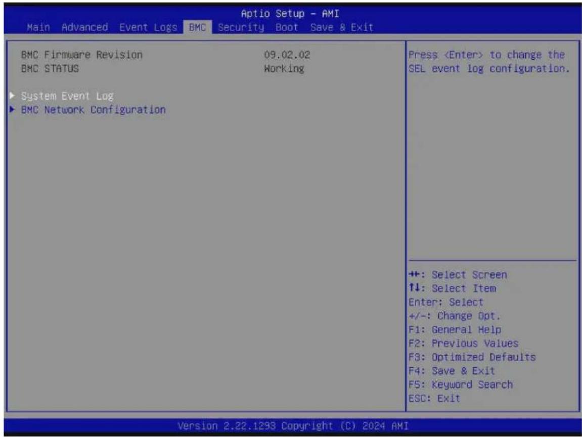
Figure 4-4. BMC Screen
System Event Log Menu
▶ System Event Log
Note: All values changed in this submenu do not take effect until computer is restarted.
Enabling/Disabling Options
SEL Components
Select Enabled to enable all system event logging upon system boot. The options are Disabled and Enabled.
Erasing Settings
Erase SEL (Available when "SEL Components" is set to Enabled)
Select (Yes, On next reset) to erase all system event logs upon next system boot. Select (Yes, On every reset) to erase all system event logs upon each system reboot. Select No to keep all system event logs after each system reboot. The options are No, (Yes, On next reset), and (Yes, On every reset).
When SEL is Full (Available when "SEL Components" is set to Enabled)
This feature defines what the BIOS should do when the system event log is full. Select Erase Immediately to erase all events in the log when the system event log is full. The options are Do Nothing and Erase Immediately.
BMC Network Configuration Menu
▶ BMC Network Configuration
Update BMC LAN Configuration
Select Yes for the BIOS to implement all IP/MAC address changes upon next system boot. The options are No and Yes.
Configure IPv4 Support
BMC LAN Selection
This feature displays the type of the BMC LAN.
BMC Network Link Status:
This feature displays the status of the BMC network link for this system.
Configuration Address Source (Available when "Update BMC LAN Configuration" is set to Yes)
Use this feature to select the source of the IPv4 connection. If Static is selected, note the IP address of the IPv4 connection and enter it to the system manually in the field. If DHCP is selected, the BIOS will search for a Dynamic Host Configuration Protocol (DHCP) server in the network that is attached to and request the next available IP address for this computer. The options are Static and DHCP.
Station IP Address
This feature displays the Station IP address in decimal and in dotted quad form (i.e., 172.29.176.131). It is available for configuration when "Configuration Address Source" above is set to Static.
Subnet Mask
This feature displays the sub-network that this computer belongs to. It is available for configuration when "Configuration Address Source" above is set to Static.
Station MAC Address
This feature displays the Station MAC address for this computer. Mac addresses are six two-digit hexadecimal numbers.
Gateway IP Address
This feature displays the Gateway IP address for this computer. This should be in decimal and in dotted quad form (i.e., 172.29.0.1). It is available for configuration when "Configuration Address Source" above is set to Static.
Configure IPv6 Support
IPv6 Address Status
This feature displays the status of the IPv6 address.
IPv6 Support (Available when "Update BMC LAN Configuration" is set to Yes)
Use this feature to enable IPv6 support. The options are Enabled and Disabled.
Configuration Address Source (Available when "IPv6 Support" is set to Enabled)
Use this feature to select the source of the IPv6 connection. If Static Configuration is selected, note the IP address of IPv6 connection and enter it to the system manually in the field. If the other two options are selected, the BIOS will search for a DHCP server in the network that is attached to and request the next available IP address for this computer. The options are Static Configuration, DHCPv6 Stateless, and DHCPv6 Stateful.
IPv6 Address ("Static," "DHCPv6 Stateless," or "DHCPv6 Stateful," depending on the option you selected for "Configuration Address Source" above)
This feature displays the station IPv6 address. It is available for configuration when "Configuration Address Source" above is set to Static Configuration.
Prefix Length
This feature displays the prefix length. It is available for configuration when "Configuration Address Source" above is set to Static Configuration.
Gateway IP
This feature displays the IPv6 gateway IP address. It is available for configuration when "Configuration Address Source" above is set to Static Configuration.
Advanced Settings (Available when "Configuration Address Source" is set to DHCPv6 Stateless)
Use this feature to set the DNS server IP. The default setting allows this system to obtain the DNS server IP automatically. The options are Auto obtain DNS server IP and Manually obtain DNS server IP.
Preferred DNS server IP (Available when "Advanced Settings" above is set to Manually obtain DNS server IP)
This feature displays the preferred DNS server IP. It can be configured via Redfish.
Alternative DNS server IP (Available when "Advanced Settings" above is set to Manually obtain DNS server IP)
This feature displays the alternative DNS server IP. It can be configured via Redfish.
Configure VLAN Support
Lan channel 1
VLAN Support (Available when "Update BMC LAN Configuration" is set to Yes)
Use this feature to enable the virtual LAN (VLAN) support. The options are Enabled and Disabled.
VLAN ID (Available when "VLAN Support" is set to Enabled)
Use this feature to create a new VLAN ID. The valid range is 1–4094. The default setting is 1.
4.6 Security
Use this menu to configure the following security settings for the system.
![Main Advanced Event Logs BMC Security Boot Save & Exit Disable Block Sid and Freeze Lock [Disabled] Administrator Password Not Installed User Password Not Installed Password Description If the Administrator's / User's password is set, then this only limits access to Setup and is asked for when entering Setup. Please set Administrator's password first in order to set User's password, if clear Administrator's password, the User's password will be cleared as well. The password length must be in the following range: Minimum length 3 Maximum length 20 Administrator Password Password Check [Setup] Hard Drive Security Frozen [Disabled] Override to allow SID authentication of TCG Storage device and to skip freeze lock command for SAT3 device.Modified value will be applicable only for next boot. +: Select Screen +: Select Item Enter: Select +/-: Change Opt. F1: General Help F2: Previous Values F3: Optimized Defaults F4: Save & Exit F5: Keyword Search ESC: Exit ++: Select Screen <<: Select Item Enter: Select +/-: Change Opt. F1: General Help F2: Previous Values F3: Optimized Defaults F4: Save & Exit F5: Keyword Search ESC: Exit Version 2.22.1234 Copyright (C) 2024 AMI](/content/2026/05/1015211/images/c9f477b6d0dcd13de1bccd2d545424d0b5a33dc4b7dad62ff2d6eaca0acc3dd1.jpg)
Figure 4-5. Security Screen
Disable Block Sid and Freeze Lock (Available when your storage devices support TCG)
Select Enabled to allow SID authentication to be performed in TCG storage devices. The options are Disabled and Enabled.
The following information is displayed:
- Administrator Password
- User Password
- Password Description
Administrator Password
This feature indicates if an administrator password has been installed. Use this feature to set the administrator password, which is required to enter the BIOS Setup utility. The length of the password can be between three and 20 characters long.
User Password (Available when "Administrator Password" has been set)
This feature indicates if a user password has been installed. Use this feature to set the user password which is required to enter the BIOS Setup utility. The length of the password can be between three and 20 characters long.
Password Check
Select Setup for the system to check for a password at Setup. Select Always for the system to check for a password at bootup and upon entering the BIOS Setup utility. The options are Setup and Always.
Hard Drive Security Frozen
Select Enabled to freeze the Lock Security feature for HDD to protect key data in hard drives from being altered. The options are Disabled and Enabled.
Lockdown Mode (Available when the DCMS key is activated)
Select Enabled to support the Lockdown Mode, which prevents the existing data or keys stored in the system from being altered or changed in an effort to preserve system integrity and security. The options are Disabled and Enabled.
Supermicro Security Erase Configuration Menu
▶ Supermicro Security Erase Configuration
Note: This submenu is available when any storage device is detected by the BIOS. For more information about this feature, please refer to our website.
Use this submenu to configure the Supermicro-proprietary Security Erase settings. When this submenu is selected, the following information is displayed. Please note that the order of the following information may differ based on the storage devices being detected.
- HDD Name: This feature displays the name of the storage device that is detected by the BIOS.
- HDD Serial Number: This feature displays the serial number of the storage device that is detected by the BIOS.
- Security Mode: This feature displays the security mode of the storage device that is detected by the BIOS.
-
Estimated Time: This feature displays the estimate time needed to perform the selected Security Erase features.
-
HDD User Pwd Status: This feature indicates if a password has been set as a storage device user password which enables configuring Supermicro Security Erase settings on the storage device by using this user password.
- TCG Device Type: This feature displays the TCG device type detected by the system.
- Admin Pwd Status: This feature indicates if a password has been set as a storage device administrator password which enables configuring Supermicro Security Erase settings on the storage device by using this administrator password.
Security Function
Select Set Password to set a storage device password which enables configuring the security settings of the storage device. Select Security Erase - Password to enter a storage device user password to enable erasing the password and the contents previously stored in the storage device. Select Security Erase - Without Password to use the manufacturer default password "111111111" as the storage device user password and enable erasing the contents of the storage device by using this default password. The options are Disabled, Set Password, Change Password, Clear Password, Security Erase - Password, Security Erase - PSID, and Security Erase - Without Password.
Notes:
- The option of Security Erase - PSID is based on the storage device support. PSID is the abbreviation for Physical Security Identification.
- The options of Change Password and Clear Password are available when "Password" below has been set.
- The option of Set Password is not available when "Password" below has been set.
Password
Use this feature to set the storage device user password, which enables configuring the Supermicro Security Erase settings by using this user password.
New Password (Available when "Password" above has been set)
Use this feature to set the new user password for the storage device, which enables configuring the Supermicro Security Erase settings by using this new user password.
HDD Security Configuration Menu
▶ P4: (Storage device model name)
This submenu is available when the storage device is detected by the BIOS. Select this device. Press
• HDD Password Description:
• HDD PASSWORD CONFIGURATION:
• Security Supported:
• Security Enabled:
- Security Locked:
- Security Frozen:
• HDD User Pwd Status:
• HDD Master Pwd Status:
Set User Password (Available when "Security Frozen:" above is No)
Press
Secure Boot Menu
▶ Secure Boot
Note: For detailed instructions on configuring Security Boot settings, please refer to the Security Boot Configuration User's Guide at https://www.supermicro.com/support/manuals.
The following information is displayed:
- System Mode
- Secure Boot
Secure Boot
Select Enabled to configure Secure Boot settings. The options are Disabled and Enabled.
Secure Boot Mode
Use this feature to select the desired secure boot mode for the system. The options are Standard and Custom.
▶ Enter Audit Mode
Note: This submenu is available when "Secure Boot Mode" is set to Custom.
Select Ok to enter the Audit Mode workflow. It will result in erasing the Platform Key (PK) variables and resetting the system to the Setup/Audit Mode.
▶ Enter Deployed Mode / Exit Deployed Mode
Note: This submenu is available when "Secure Boot Mode" is set to Custom.
Select Ok to reset system to the User Mode or to the Deployed Mode.
▶ Key Management
Note: This submenu is available when "Secure Boot Mode" is set to Custom.
The following information is displayed:
- Vendor Keys
Provision Factory Defaults
Select Enabled to install provision factory default settings after a platform reset while the system is in the Setup Mode. The options are Disabled and Enabled.
Note: This submenu is available when any secure keys have been installed.
Select Yes to restore manufacturer default keys to ensure system security. The options are Yes and No. Selecting Yes will reset system to the Deployed mode.
▶ Reset To Setup Mode
Note: This submenu is available when any secure keys have been installed.
This feature resets the system to the Setup Mode. The options are Yes and No.
▶Enroll Efi Image
This feature allows the Efi image to run in the secure boot mode, which will enroll the SHA256 Hash certificate of a PE image into the Authorized Signature Database (DB).
▶ Export Secure Boot Variables
Note: This submenu is available when any secure keys have been installed.
This feature exports the NVRAM contents of secure boot variables to a storage device.
The options are Yes and No.
Secure Boot variable / Size / Keys / Key Source
▶ Platform Key (PK)
Use this feature to enter and configure a set of values to be used as platform firmware keys for the system. These values also indicate the sizes, key numbers, and the sources of the authorized signatures. Select Update to update the platform key.
▶Key Exchange Keys (KEK)
Use this feature to enter and configure a set of values to be used as Key Exchange Keys for the system. These values also indicate the sizes, key numbers, and the sources of the authorized signatures. Select Update to update the Key Exchange Keys. Select Append to append the Key Exchange Keys.
▶ Authorized Signatures (db)
Use this feature to enter and configure a set of values to be used as Authorized Signatures for the system. These values also indicate the sizes, key numbers, and sources of the authorized signatures. Select Update to update the Authorized Signatures. Select Append to append the new Authorized Signatures.
▶ Forbidden Signatures (dbx)
Use this feature to enter and configure a set of values to be used as Forbidden Signatures for the system. These values also indicate sizes, key numbers, and key sources of the forbidden signatures. Select Update to update the Forbidden Signatures. Select Append to append the Forbidden Signature.
▶ Authorized TimeStamps (dbt)
Use this feature to set and save the timestamps for the Authorized Signatures, which will indicate the time when these signatures are entered into the system. These values also indicate sizes, keys, and key sources of the authorized timestamps. Select Update to update the Authorized TimeStamps. Select Append to append the Authorized TimeStamps.
▶ OsRecovery Signatures (dbr)
Use this feature to set and save the Authorized Signatures used for OS recovery. Select Update to update the OsRecovery Signatures. These values also indicate sizes, keys, and key sources of the OsRecovery Signatures. Select Append to append the OsRecovery Signatures.
TCG Storage Security Configuration Menu
▶(Storage device model name)
Note: This submenu is available when the storage device is compliant with TCG specifications.
Select this device. Press
• TCG Storage Security Password Description:
- PASSWORD CONFIGURATION:
• Security Subsystem Class:
• Security Supported:
• Security Enabled:
- Security Locked:
- Security Frozen:
- User Pwd Status:
- Admin Pwd Status:
Set Admin Password
Use this feature to set the administrator password for this storage device.
Set User Password (Available when "Set Admin Password" has been set)
Use this feature to set the user password for this storage device.
Device Reset
Use this feature to reset the password configuration for this storage device.
4.7 Boot
Use this menu to configure Boot settings.
![Aptio Setup - AMI Main Advanced Event Logs BMC Security Boot Save & Exit FIXED BOOT ORDER Priorities Boot Option #1 [UEFI Hard Disk] Boot Option #2 [UEFI CD/DVD] Boot Option #3 [UEFI USB Hard Disk] Boot Option #4 [UEFI USB CD/DVD] Boot Option #5 [UEFI USB Key:UEFI: USB, Partition 1] Boot Option #6 [UEFI USB Floppy] Boot Option #7 [UEFI USB Lan] Boot Option #8 [UEFI Network:(B62/DO/F0) UEFI PXE IPv4 Intel(R) Ethernet Controller XS50(MAC: )] Boot Option #9 [UEFI AP:UEFI: Built-in EFI Shell] ► Add New Boot Option ► Delete Boot Option ► UEFI USB Key Drive BBS Priorities ► UEFI NETWORK Drive BBS Priorities ► UEFI Application Boot Priorities ▲ Specifies the Boot Device Priority sequence from available UEFI Application. ++: Select Screen ↑↓: Select Item Enter: Select +/-: Change Opt. F1: General Help F2: Previous Values F3: Optimized Defaults F4: Save & Exit ▼ F5: Keyword Search ESC: Exit Version 2.22.1294 Copyright (C) 2024 AMI](/content/2026/05/1015211/images/3247a93ced3f85c4525879063706f41ed777f4b0a546b3ab48e809d331ea33b7.jpg)
Figure 4-6. Boot Screen
FIXED BOOT ORDER Priorities
Use this feature to prioritize the order of a bootable device from which the system will boot. Press
- Boot Option #1 – Boot Option #9
▶ Add New Boot Option
Note: This submenu is available when any storage device is detected by the BIOS.
Use this feature to add a new boot option to the boot priority features for system boot.
Add boot option
Use this feature to specify the name for the new boot option.
Path for boot option
Use this feature to enter the path for the new boot option in the format fsx:\path\filename.efi.
Boot option File Path
Use this feature to specify the file path for the new boot option.
Create
After setting the name and the file path for the boot option, press
▶ Delete Boot Option
Use this feature to select a boot device to delete from the boot priority list.
Delete Boot Option
Use this feature to remove an EFI boot option from the boot priority list.
▶UEFI NETWORK Drive BBS Priorities
Use this feature to set the system boot order of detected devices.
▶ UEFI Application Boot Priorities
Use this feature to set the system boot order of detected devices.
▶UEFI USB Key Drive BBS Priorities
Use this feature to set the system boot order of detected devices.
4.8 Save & Exit
Select Save & Exit from the BIOS Setup screen to configure the settings below.
| Main Advanced Event Logs BMC Security Boot Save & Exit | |
| Save Options Discard Changes and Exit Save Changes and Reset Save Changes Discard Changes Default Options Restore Optimized Defaults Save as User Defaults Restore User Defaults Boot Override (B62/D0/F0) UEFI PXE IPv4 Intel(R) Ethernet Controller X550( ) (B62/D0/F1) UEFI PXE IPv4 Intel(R) Ethernet Controller X550( ) (B62/D0/F0) UEFI PXE IPv6 Intel(R) Ethernet Controller X550( ) (B62/D0/F1) UEFI PXE IPv6 Intel(R) Ethernet Controller X550( ) UEFI: Built-in EFI Shell Launch EFI Shell from filesystem device | Exit system setup without saving any changes. +: Select Screen ↑↓: Select Item Enter: Select +/-: Change Opt. F1: General Help F2: Previous Values F3: Optimized Defaults F4: Save & Exit F5: Keyword Search ESC: Exit |
| Version 2.22.1293 Copyright (C) 2024 AMI | |
Figure 4-7. Save & Exit Screen
Save Options
Discard Changes and Exit
Use this feature to exit from the BIOS Setup utility without making any permanent changes to the system configuration and reboot the computer.
Save Changes and Reset
On completing the system configuration changes, use this feature to exit the BIOS Setup utility and reboot the computer for the new system configuration parameters to take effect.
Save Changes
On completing the system configuration changes, use this feature to save all changes made. This will not reset (reboot) the system.
Discard Changes
Select this feature and press
Default Options
Restore Optimized Defaults
Select this feature and press
Note: Please reboot the system for the changes to take effect, which ensures that this system has the optimized default settings.
Save As User Defaults
Select this feature and press
Select this feature and press
Boot Override
Note: Use this section to override the Boot priorities sequence in the Boot menu, and immediately boot the system with a device specified here instead of the one specified in the boot list. This is a one-time boot override.
Appendix A:
Software
After the X14SBW-F/-TF motherboard has been installed, you can install the Operating System (OS), configure RAID settings and install the drivers.
Microsoft Windows OS Installation
If you will be using RAID, you must configure RAID settings before installing the Windows OS and the RAID driver. Refer to the RAID Configuration User Guides posted on our website at https://www.supermicro.com/support/manuals.
Installing the OS
- Create a method to access the Microsoft Windows installation ISO file. That might be a Media drive, using a USB flash or media drive, or the BMC KVM console.
- Retrieve the proper drivers. Go to the Supermicro web page for your motherboard and click on "Download the Latest Drivers and Utilities," select the proper driver, and copy it to a USB flash drive.
- Boot from a bootable device with Windows OS installation. You can see a bootable device list by pressing
during the system bootup.

Figure A-1. Select Boot Device
- During Windows Setup, continue to the dialog box where you select the drives on which to install Windows. If the disk you want to use is not listed, click on the "Load driver" link at the bottom left corner.
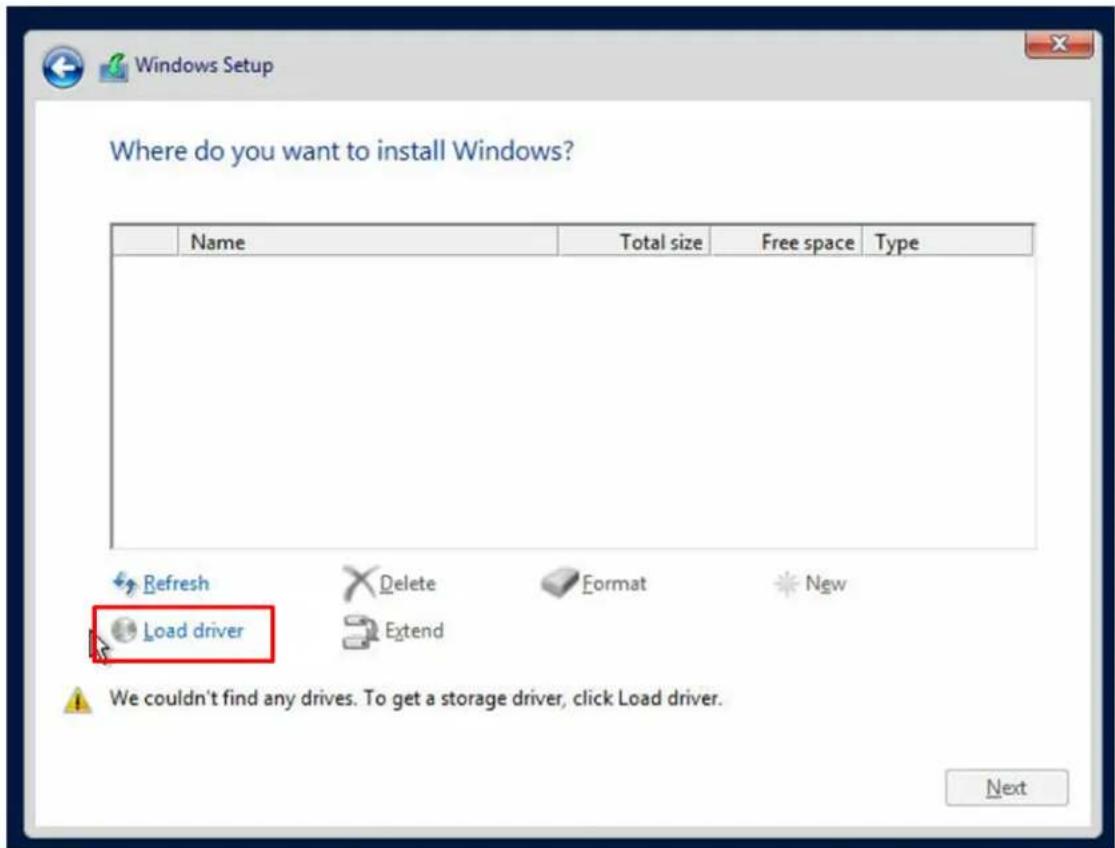
Figure A-2. Load Driver Link
To load the driver, browse the USB flash drive for the proper driver files.
- Once all devices are specified, continue with the installation.
- After the Windows OS installation has completed, the system will automatically reboot multiple times for system updates.
A.1 Driver Installation
The Supermicro website contains drivers and utilities for your system at https://www.supermicro.com/wdl. Some of these must be installed, such as the chipset driver.
After accessing the website, go into the CDR_Images (in the parent directory of the above link) and locate the ISO file for your motherboard. Download this file to a USB flash or media drive. You may also use a utility to extract the ISO file if preferred.
Another option is to go to the Supermicro website at https://www.supermicro.com. Find the product page for your motherboard and download the latest drivers and utilities.
Insert the flash drive or disk, and the screenshot shown below should appear.
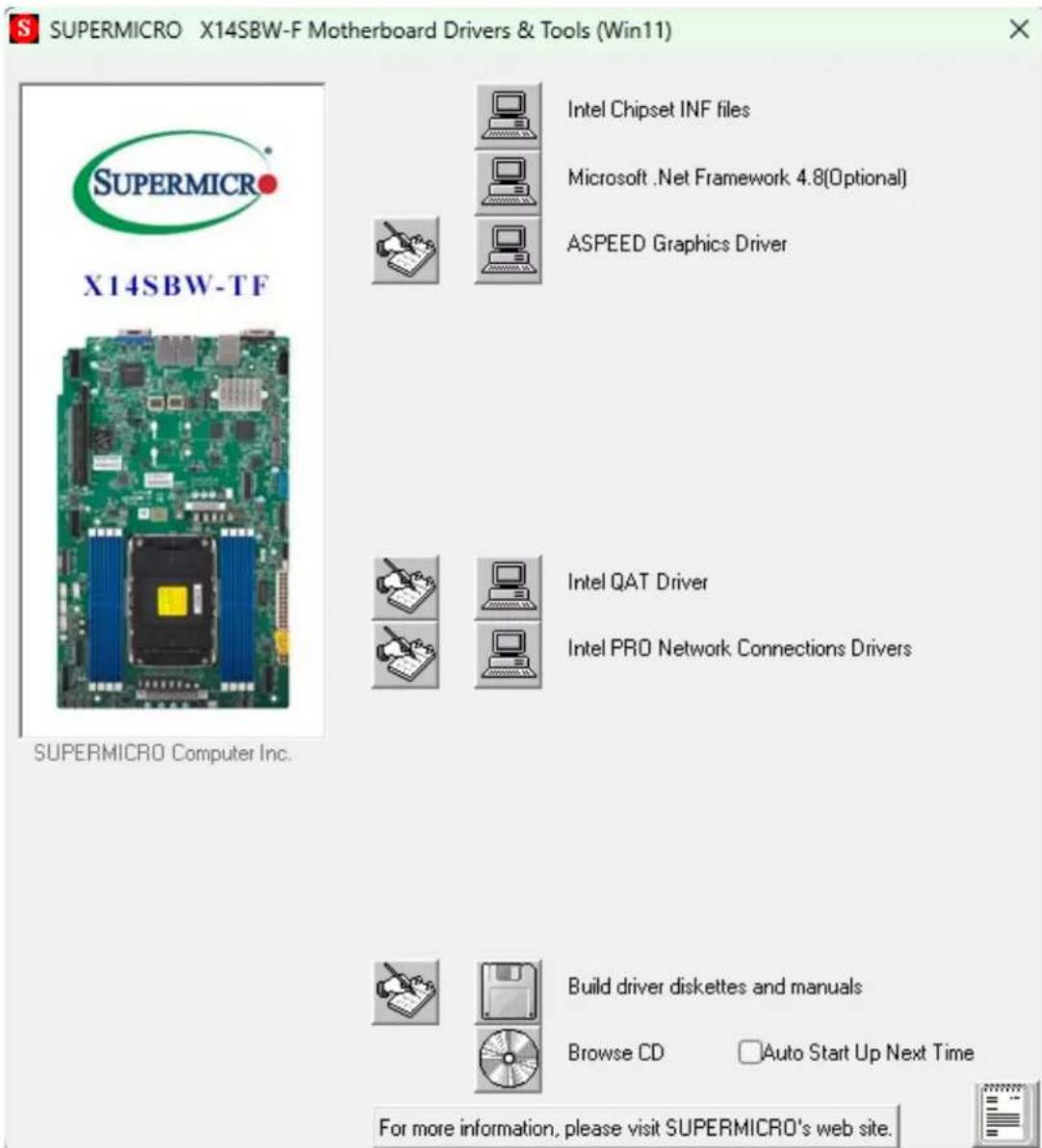
Figure A-3. Driver & Tools Installation Screen
Note: Click the icons showing a hand writing on paper to view the readme files for each item. Click the computer icons to the right of these items to install each item (from top to bottom) one at a time. After installing each item, you must reboot the system before moving on to the next item on the list. The bottom icon with a CD on it allows you to view the entire contents.
BMC
The X14SBW-F/- TF motherboard provides remote access, monitoring, and management through the baseboard management controller (BMC) and other management controllers distributed among different system modules. There are several BIOS settings that are related to BMC. For general documentation and information on BMC, visit our website at: https://www.supermicro.com/en/solutions/management-software/bmc-resources.
BMC ADMIN User Password
For security, each system is assigned a unique default BMC password for the ADMIN user. The password can be found on a sticker on the motherboard and a sticker on the chassis, for Supermicro chassis. The sticker also displays the BMC MAC address. If necessary, the password can be reset using the Supermicro IPMICFG tool.

Figure A-4. BMC Password Label
Appendix B:
Standardized Warning Statements
The following statements are industry standard warnings, provided to warn the user of situations which have the potential for bodily injury. Should you have questions or experience difficulty, contact Supermicro's Technical Support department for assistance. Only certified technicians should attempt to install or configure components.
Read this section in its entirety before installing or configuring components in the Supermicro X14SBW-F/-TF motherboard.
These warnings may also be found on our website at https://www.supermicro.com/about/policies/safety_information.cfm.
Battery Handling

CAUTION There is risk of explosion if the battery is replaced by an incorrect type.
Replace the battery only with the same or equivalent type recommended by the manufacturer. Dispose of used batteries according to the manufacturer's instructions.
電池の取り扱い
Warning! Ultimate disposal of this product should be handled according to all national laws and regulations.
製品の廃棄


- Preface
- About This Manual
- Notes
- Conventions Used in the Manual
- Contents
- Contacting Supermicro 10.
- Chapter 1: Introduction 11.
- Quick Reference 12
- Platform Overview 22
- Special Features 23
- System Health Monitoring 24.
- ACPI Features 25
- Chapter 2: Component Installation
- Static-Sensitive Devices
- Motherboard Installation
- Processor and Heatsink Installation
- Memory Support and Installation 51.
- Battery Removal and Installation 57.
- Connections, Jumpers, and LEDs 59
- Chapter 3: Troubleshooting 82
- Chapter 4: UEFI BIOS 92
- Contacting Supermicro
- Headquarters
- Europe
- Asia-Pacific
- Chapter 1:
- Introduction
- System Health Monitoring 24
- ACPI Features
- Quick Reference
- Checklist
- Motherboard Layout
- Notes:
- Platform Overview
- Special Features
- Recovery from AC Power Loss
- System Health Monitoring
- Onboard Voltage Monitors
- Fan Status Monitor with Firmware Control
- Environmental Temperature Control
- Chapter 2:
- Component Installation
- Static-Sensitive Devices 28
- Motherboard Installation 29
- Processor and Heatsink Installation 32
- Memory Support and Installation 51
- Battery Removal and Installation 57
- Connections, Jumpers, and LEDs 59.
- Precautions
- Unpacking
- Tools Needed
- Installing the Motherboard
- LGA 4710 Socket E2 Processors
- Overview of the Processor Carrier Assembly
- Overview of the Processor Socket
- Overview of the Processor Heatsink Module
- Creating the Processor Carrier Assembly
- Assembling the Processor Heatsink Module
- Preparing the Processor Socket for Installation
- Preparing to Install the PHM into the Processor Socket
- Installing the Processor Heatsink Module
- Removing the Processor Heatsink Module
- Memory Support and Installation
- Memory Support
- General Guidelines for Optimizing Memory Performance
- DIMM Installation
- DIMM Removal
- Battery Removal and Installation
- Battery Removal
- Proper Battery Disposal
- Battery Installation
- Connections, Jumpers, and LEDs
- Power Supply and Power Connections
- Power Supply
- Power Connectors
- Headers and Connections
- Chassis Intrusion
- External BMC I²C Header
- Fan Headers
- Inlet Sensor Header
- M.2 Slots
- MCIO PCIe 5.0 x8 Connectors
- NC-SI Connection
- NVMe SMBus Headers
- Power SMB (I²C) Header
- Standby Power
- SATA 3.0 Ports (Slimline SAS)
- TPM/Port 80 Header
- VROC RAID Key Header
- Front Control Panel Header
- Power Button
- Reset Button
- Power Fail LED
- Overheat/Fan Fail and UID LED
- HDD LED/UID Switch
- Power LED
- NMI Button
- I/O Ports
- COM Port
- LAN Ports
- Unit Identifier Button
- USB Ports
- VGA Port
- Jumper Settings
- CMOS Clear
- I²C Buses for VRM
- LAN Port Enable/Disable
- Onboard TPM Enable/Disable
- LED Indicators
- BMC Heartbeat LED
- M.2 LEDs
- Onboard Power LED
- Unit ID (UID) LED
- Chapter 3:
- Troubleshooting
- Troubleshooting Procedures 83
- Technical Support Procedures 87
- Motherboard Battery 88
- Troubleshooting Procedures
- Before Power On
- No Power
- No Video
- System Boot Failure
- Memory Errors
- Losing the System's Setup Configuration
- When the System Becomes Unstable
- Technical Support Procedures
- Motherboard Battery
- Where to Get Replacement Components
- Returning Merchandise for Service
- Feedback
- Chapter 4:
- UEFI BIOS
- Introduction
- Updating BIOS
- Starting the Setup Utility
- Main Setup
- System Date/System Time
- Supermicro X14SBW-F/-TF
- BIOS Version
- Build Date
- CPLD Version
- Memory Information
- Total Memory
- Advanced Setup Configuration
- Bootup NumLock State
- Wait For "F1" If Error
- Re-try Boot
- Power Configuration
- Watch Dog Function
- Watch Dog Action (Available when "Watch Dog Function" is set to Enabled)
- Restore on AC Power Loss
- Power Button Function
- CPU Configuration Menu
- ▶ CPU Configuration
- Hyper-Threading [ALL]
- Hardware Prefetcher
- Adjacent Cache Prefetch
- DCU Streamer Prefetcher
- DCU IP Prefetcher
- LLC Prefetch
- Homeless Prefetch
- AMP Prefetch
- APIC Physical Mode
- TXT Support
- Intel Virtualization Technology
- Enable SMX
- PPIN Control
- AES-NI
- Advanced Power Management Configuration Menu
- ▶ Advanced Power Management Configuration
- Workload Profile
- Power Performance Tuning
- ENERGY\_PERF\_BIAS\_CFG Mode (ENERGY PERFORMANCE BIAS CONFIGURATION Mode)
- CPU P State Control Menu
- ▶ CPU P State Control
- Intel SST-PP
- AVX P1
- Dynamic SST-PP
- SpeedStep (P-States)
- EIST PSD Function
- ▶ Hardware PM State Control
- Hardware P-States
- ▶ CPU C State Control
- Monitor MWAIT
- ACPI C1 Enumeration
- ACPI C6x Enumeration
- ▶ Package C State Control
- Package C State
- LTR IIO Input
- CPU1 Core Disable Bitmap Menu
- ▶CPU1 Core Disable Bitmap
- Disable Bitmap[0]:
- Disable Bitmap[1]:
- Chipset Configuration Menu
- ▶ Chipset Configuration
- Degrade Precedence
- Link L0p Enable
- Link L1 Enable
- KTI Prefetch
- IO Directory Cache (IODC)
- SNC
- XPT Prefetch
- Stale AtoS
- LLC Dead Line Alloc
- Memory Configuration Menu
- ▶ Memory Configuration
- Enforce DDR Memory Frequency POR
- Host Memory Frequency
- Global Scrambling
- ▶ Memory Topology
- ▶ Memory Map
- Intel(R) Flat Memory Mode Support
- DDR CXL Heterogeneous Interleave Support
- ▶ Memory RAS Configuration
- Mirror Mode
- UEFI ARM Mirror
- Mirror TAD0
- Correctable Error Threshold
- DDR PPR Type
- Enhanced PPR
- Memory PFA Support (Available when the DCMS key is activated)
- Security Configuration Menu
- ▶ Security Configuration
- Memory Encryption (TME)
- Total Memory Encryption Multi-Tenant (TME-MT)
- Memory Integrity
- TME Encryption Algorithm
- Trust Domain Extensions (TDX) (Available when your motherboard supports Intel TDX)
- TDX Secure Arbitration Mode Loader (SEAM Loader) (Available when your motherboard supports Intel TDX and when "Trust Domain Extension (TDX)" is set to Enabled)
- TME-MT/TDX Key Split (Available when "Trust Domain Extension (TDX)" is set to Enabled)
- Processor Reserved Memory [Outputs]
- Software Guard Extension (SGX) [Outputs]
- Software Guard Extension (SGX) [Inputs]
- SGX Factory Reset
- SW Guard Extensions (SGX)
- SGX Package Info In-Band Access
- SGX PRMRR Size Requested (Available when "SW Guard Extensions (SGX)" is set to Enabled)
- SGX QoS (Available when "SW Guard Extensions (SGX)" is set to Enabled)
- Select Owner EPOCH Input Type (Available when "SW Guard Extensions (SGX)" is set to Enabled)
- Software Guard Extensions Epoch 0
- Software Guard Extensions Epoch 1
- SGXLEPUBKEYHASHx Write Enable (Available when "SW Guard Extensions (SGX)" is set to Enabled)
- SGXLEPUBKEYHASH0 (Available when both "SW Guard Extensions (SGX)" and "SGXLEPUBKEYHASHx Write Enable" are set to Enabled)
- SGXLEPUBKEYHASH1 (Available when both "SW Guard Extensions (SGX)" and "SGXLEPUBKEYHASHx Write Enable" are set to Enabled)
- SGXLEPUBKEYHASH2 (Available when both "SW Guard Extensions (SGX)" and "SGXLEPUBKEYHASHx Write Enable" are set to Enabled)
- SGXLEPUBKEYHASH3 (Available when both "SW Guard Extensions (SGX)" and "SGXLEPUBKEYHASHx Write Enable" are set to Enabled)
- SGX Auto MP Registration (Available when "SW Guard Extensions (SGX)" is set to Enabled)
- IIO Configuration Menu
- ▶ IIO Configuration
- PCIe ASPM Support (Global)
- NVMe Mode Switch
- PCIe PLL SSC
- CPU1 Configuration Menu
- ▶ CPU1 Configuration
- ▶ PCI Express 1 / PCI Express 2 / PCI Express 3 / PCI Express 4 / PCI Express 5
- Bifurcation
- Intel VMD Technology
- ▶ M.2-C1 / M.2-C2 / NVME0 / NVME1 / NVME5 / NVME6 / NVME7 / NVME8
- Requested Link Speed
- PCIe Port Max Payload Size
- MCTP
- ▶ Intel VT for Directed I/O (VT-d)
- Pre-boot DMA Protection
- PCIe ACSCTL
- Trusted Computing Menu
- ▶ Trusted Computing
- Security Device Support
- SHA-1 PCR Bank (Available when "Security Device Support" is set to Enabled)
- SHA256 PCR Bank (Available when "Security Device Support" is set to Enabled)
- SHA384 PCR Bank (Available when "Security Device Support" is set to Enabled)
- Pending Operation (Available when "Security Device Support" is set to Enabled)
- Platform Hierarchy (Available when "Security Device Support" is set to Enabled)
- Storage Hierarchy (Available when "Security Device Support" is set to Enabled)
- Endorsement Hierarchy (Available when "Security Device Support" is set to Enabled)
- PH Randomization
- ACPI Settings Menu
- ▶ ACPI Settings
- NUMA
- Virtual NUMA
- Number of Virtual NUMA Nodes (Available when "Virtual NUMA" is set to Enabled)
- WHEA Support
- Super IO Configuration Menu
- ▶ Super IO Configuration
- Serial Port 1 Configuration Menu
- ▶ Serial Port 1 Configuration
- Serial Port 1
- Device Settings (Available when "Serial Port 1" above is set to Enabled)
- Change Settings (Available when "Serial Port 1" above is set to Enabled)
- Serial Port 2 Configuration Menu
- ▶ Serial Port 2 Configuration
- Serial Port 2/SOL ("Serial Port 2" or "SOL" based on your system support)
- Device Settings (Available when "Serial Port 2/SOL" above is set to Enabled)
- Change Settings (Available when "Serial Port 2/SOL" above is set to Enabled)
- Serial Port 2 Attribute (Available for Serial Port 2 only)
- Serial Port Console Redirection Menu
- ▶ Serial Port Console Redirection
- COM1 (Available when your system supports the serial port of COM1)
- Console Redirection
- SOL/COM2
- ▶ Console Redirection Settings
- Terminal Type
- Bits Per Second
- Data Bits
- Parity
- Stop Bits
- Flow Control
- VT-UTF8 Combo Key Support
- Recorder Mode
- Resolution 100x31
- Putty KeyPad
- Serial Port for Out-of-Band Management/Windows Emergency Management Services (EMS)
- Console Redirection EMS
- Out-of-Band Mgmt Port
- Terminal Type EMS
- Bits Per Second EMS
- Flow Control EMS
- Network Stack Configuration Menu
- ▶ Network Stack Configuration
- Network Stack
- IPv4 PXE Support (Available when "Network Stack" is set to Enabled)
- IPv4 HTTP Support (Available when "Network Stack" is set to Enabled)
- IPv6 PXE Support (Available when "Network Stack" is set to Enabled)
- IPv6 HTTP Support (Available when "Network Stack" is set to Enabled)
- PXE Boot Wait Time (Available when "Network Stack" is set to Enabled)
- Media Detect Count (Available when "Network Stack" is set to Enabled)
- MAC:(MAC address)-IPv4 Network Configuration Menu
- ▶ MAC:(MAC address)-IPv4 Network Configuration
- Configured
- Enable DHCP (Available when "Configured" is set to Enabled)
- Local IP Address (Available when "Configured" is set to Enabled and "Enabled DHCP" is set to Disabled)
- Local NetMask (Available when "Configured" is set to Enabled and "Enabled DHCP" is set to Disabled)
- Local Gateway (Available when "Configured" is set to Enabled and "Enabled DHCP" is set to Disabled)
- Local DNS Servers (Available when "Configured" is set to Enabled and "Enabled DHCP" is set to Disabled)
- Save Changes and Exit
- MAC:(MAC address)-IPv6 Network Configuration Menu
- ▶ MAC:(MAC address)-IPv6 Network Configuration
- ▶ Enter Configuration Menu
- Interface ID
- DAD Transmit Count
- Policy
- ▶ Advanced Configuration
- PCIe/PCI/PnP Configuration Menu
- ▶ PCIe/PCI/PnP Configuration
- PCI Devices Common Settings:
- Re-Size BAR Support
- SR-IOV Support (Unavailable when "Workload Profile" is set to Virtualization)
- ARI Support
- MMCFG Base
- MMCFG Size
- MMIO High Base
- MMIO High Granularity Size
- Bus Master Enable
- NVMe Firmware Source
- VGA Priority
- Onboard Video Option ROM
- Onboard LAN1 Option ROM
- Onboard LAN2 Option ROM
- AOC-ATG-i2S LAN1 OPROM / Onboard SAS Option ROM / Onboard LAN1 Option ROM / Onboard NVMe1 Option ROM – Onboard NVMe24 Option ROM
- HTTP Boot Configuration Menu
- ▶ HTTP Boot Configuration
- HTTP Boot Policy
- HTTPS Boot Checks Hostname
- Priority of HTTP Boot
- Select IPv4 or IPv6
- Boot Description
- Boot URI
- Supermicro KMS Server Configuration Menu
- ▶ Supermicro KMS Server Configuration
- Supermicro KMS Server IP address
- Second Supermicro KMS Server IP address
- Supermicro KMS TCP Port number
- KMS Time Out
- TimeZone
- Client UserName
- Client Password
- Super-Guardians Configuration Menu
- ▶ Super-Guardians Configuration
- Super-Guardians Protection Policy
- KMS Security Policy (Available when "TPM Security Policy" and "USB Security Policy" are set to Disabled)
- KMS Server Retry Count (Available when "TPM Security Policy" and "USB Security Policy" are set to Disabled)
- TPM Security Policy (Available when "KMS Security Policy" and "USB Security Policy" are set to Disabled)
- Load Authentication-Key (Available when "KMS Security Policy," "TPM Security Policy," and "USB Security Policy" are set to Disabled)
- Save Authentication-Key (Available when "TPM Security Policy" is set to Enabled)
- USB Security Policy (Available when "KMS Security Policy" and "TPM Security Policy" are set to Disabled)
- Intel(R) Ethernet Controller Menu
- ▶Intel (R) Ethernet Controller (Ethernet controller) - (MAC address)
- ▶ NIC Configuration
- Link Speed
- Wake On LAN
- LLDP Agent
- Blink LEDs
- TLS Authenticate Configuration Menu
- ▶ TLS Authenticate Configuration
- ▶ Server CA Configuration
- ▶Enroll Certification
- ▶Enroll Certification Using File
- Certification GUID
- ▶ Commit Changes and Exit
- ▶ Discard Changes and Exit
- ▶ Delete Certification
- ▶ Client Certification Configuration
- Asmedia AHCI Controller Menu
- ▶ Asmedia AHCI Controller Menu / Asmedia AHCI Controller Menu
- Driver Health Menu
- ▶ Driver Health
- Event Logs
- ▶ Change SMBIOS Event Log Settings
- Enabling/Disabling Options
- SMBIOS Event Log
- Erasing Settings
- Erase Event Log (Available when "SMBIOS Event Log" is set to Enabled)
- When Log is Full (Available when "SMBIOS Event Log" is set to Enabled)
- SMBIOS Event Log Standard Settings
- METW (Available when "SMBIOS Event Log" is set to Enabled)
- ▶ View SMBIOS Event Log
- BMC
- System Event Log Menu
- ▶ System Event Log
- SEL Components
- Erase SEL (Available when "SEL Components" is set to Enabled)
- When SEL is Full (Available when "SEL Components" is set to Enabled)
- BMC Network Configuration Menu
- ▶ BMC Network Configuration
- Update BMC LAN Configuration
- Configure IPv4 Support
- BMC LAN Selection
- BMC Network Link Status:
- Configuration Address Source (Available when "Update BMC LAN Configuration" is set to Yes)
- Station IP Address
- Subnet Mask
- Station MAC Address
- Gateway IP Address
- Configure IPv6 Support
- IPv6 Address Status
- IPv6 Support (Available when "Update BMC LAN Configuration" is set to Yes)
- Configuration Address Source (Available when "IPv6 Support" is set to Enabled)
- IPv6 Address ("Static," "DHCPv6 Stateless," or "DHCPv6 Stateful," depending on the option you selected for "Configuration Address Source" above)
- Prefix Length
- Gateway IP
- Advanced Settings (Available when "Configuration Address Source" is set to DHCPv6 Stateless)
- Preferred DNS server IP (Available when "Advanced Settings" above is set to Manually obtain DNS server IP)
- Alternative DNS server IP (Available when "Advanced Settings" above is set to Manually obtain DNS server IP)
- Configure VLAN Support
- Lan channel 1
- VLAN Support (Available when "Update BMC LAN Configuration" is set to Yes)
- VLAN ID (Available when "VLAN Support" is set to Enabled)
- Security
- Administrator Password
- User Password (Available when "Administrator Password" has been set)
- Password Check
- Hard Drive Security Frozen
- Lockdown Mode (Available when the DCMS key is activated)
- Supermicro Security Erase Configuration Menu
- ▶ Supermicro Security Erase Configuration
- Security Function
- Password
- New Password (Available when "Password" above has been set)
- HDD Security Configuration Menu
- ▶ P4: (Storage device model name)
- Set User Password (Available when "Security Frozen:" above is No)
- Secure Boot Menu
- ▶ Secure Boot
- Secure Boot
- Secure Boot Mode
- ▶ Enter Audit Mode
- ▶ Enter Deployed Mode / Exit Deployed Mode
- ▶ Key Management
- Provision Factory Defaults
- ▶ Reset To Setup Mode
- ▶Enroll Efi Image
- ▶ Export Secure Boot Variables
- Secure Boot variable / Size / Keys / Key Source
- ▶ Platform Key (PK)
- ▶Key Exchange Keys (KEK)
- ▶ Authorized Signatures (db)
- ▶ Forbidden Signatures (dbx)
- ▶ Authorized TimeStamps (dbt)
- ▶ OsRecovery Signatures (dbr)
- TCG Storage Security Configuration Menu
- ▶(Storage device model name)
- Set Admin Password
- Set User Password (Available when "Set Admin Password" has been set)
- Device Reset
- Boot
- FIXED BOOT ORDER Priorities
- ▶ Add New Boot Option
- Add boot option
- Path for boot option
- Boot option File Path
- Create
- ▶ Delete Boot Option
- Delete Boot Option
- ▶UEFI NETWORK Drive BBS Priorities
- ▶ UEFI Application Boot Priorities
- ▶UEFI USB Key Drive BBS Priorities
- Save & Exit
- Save Options
- Discard Changes and Exit
- Save Changes and Reset
- Save Changes
- Discard Changes
- Default Options
- Restore Optimized Defaults
- Save As User Defaults
- Boot Override
- Appendix A:
- Software
- Microsoft Windows OS Installation
- Installing the OS
- A.1 Driver Installation
- Figure A-3. Driver & Tools Installation Screen
- BMC
- BMC ADMIN User Password
- Appendix B:
- Standardized Warning Statements
- Battery Handling
Brand : Supermicro
Model : X14SBW-TF
Category : Computer