
Delta - Air conditioner Calorex - Free user manual and instructions
Find the device manual for free Delta Calorex in PDF.


| Product Type | Dehumidifier |
| Model | Delta |
| Brand | Calorex |
| Dimensions (H x W x D) | 50 cm x 35 cm x 25 cm |
| Weight | 12 kg |
| Power Supply | 220-240 V, 50 Hz |
| Power Consumption | 300 W |
| Dehumidification Capacity | 20 L/day (at 30°C, 80% RH) |
| Water Tank Capacity | 4 L |
| Air Flow Rate | 150 m³/h |
| Noise Level | 45 dB(A) |
| Refrigerant Type | R290 |
| Operating Temperature Range | 5°C – 35°C |
| Humidity Control | Adjustable hygrostat (30% – 80% RH) |
| Timer Function | Yes, 24-hour timer |
| Auto Defrost | Yes, automatic |
| Continuous Drainage | Yes, with hose connection |
| Air Filter | Washable pre-filter |
| Castors | Yes, 2 wheels |
| Energy Efficiency Class | Class A |
| Warranty | 2 years |
Frequently Asked Questions - Delta Calorex
User questions about Delta Calorex
0 question about this device. Answer the ones you know or ask your own.
Ask a new question about this device
Download the instructions for your Air conditioner in PDF format for free! Find your manual Delta - Calorex and take your electronic device back in hand. On this page are published all the documents necessary for the use of your device. Delta by Calorex.
USER MANUAL Delta Calorex
natural_image
Exterior view of a large industrial machine with blue internal components and metallic casing (no visible text or symbols)
HEALTH AND SAFETY WARNING

As the dehumidifier embodies electrical and rotational equipment, ONLY competent persons should carry out any work on this type of machine.
(SEE GUARANTEE)
DELTA SYSTEM, OWNER INSTALLATION MANUAL (SD675650 ISSUE 6)
CONTENTS
HEALTH AND SAFETY WARNING ....4
FEATURES OF THE DELTA RANGE....5
1.0 HOW THE DELTA SYSTEM WORKS......6
1.1 HOW THE AIR FLOWS THROUGH THE DELTA .....7
1.2 HOW TO USE THE DELTA 8
1.3 TOUCHSCREEN USER INTERFACE....9
1.4 DATA ENTRY 15
2.0 USER SETTINGS....16
2.1 ADVANCED SETTINGS 26
2.2 REMOTE ACCESS TO THE DELTA TOUCHSCREEN ..... 34
3.0 INSTALLATION 37
3.1 SITING, MACHINE LOCATION 38
3.2 AIR FLOW (POOL HALL AIR)....40
3.3 FRESH AIR AND EXHAUST AIR....41
3.4 PLUMBING INSTALLATION 42
3.5 ELECTROLYTIC CORROSION IN SWIMMING POOLS..46
3.6 ELECTRICAL CONNECTIONS 47
3.7 ELECTRICAL INSTALLATION....48
3.8 VOLT FREE TERMINALS AND REMOTE ACCESS......49
3.9 AIR QUALITY SENSOR IF OPTION FITTED (KIT D) ..... 52
3.10 NETWORK CONNECTION....52
3.11 BMS CONNECTION
(BUILDING MANAGEMENT SYSTEM) 53
3.12 OPTIONAL REMOTE SENSOR BOX .... 54
4.0 AFTER INSTALLATION 55
4.1 MAINTENANCE 57
4.2 CIRCUIT DIAGRAMS....58
5.0 DATA SHEET 61
5.1 LPHW HEATING DATA - DELTA WITH STANDARD AIR HEATER 62
5.2 LPHW HEATING DATA - DELTA WITH UPGRADED AIR HEATER 63
6.0 DIMENSIONS....64
7.0 DELTA CONFIGURATIONS 78
8.0 WARRANTY CONDITIONS....80
HEALTH AND SAFETY WARNING

This appliance can be used by children from eight years and above and persons with reduced physical, sensory or mental capabilities or lack of experience and knowledge if they have been given supervision or instruction concerning the use of the appliance in a safe way and understand the hazards involved. Children should not play with the appliance. Cleaning and maintenance shall not be made by children without supervision.
This machine is classified as "NOT ACCESSIBLE TO THE PUBLIC" and therefore should be located in a machine room and serviced by qualified personnel.
Disconnect from the mains supply and wait three minutes before removing panels and commencing work on this machine.
FEATURES OF THE DELTA RANGE
The Delta range consists of nine models: 1, 2, 4, 6, 8, 10, 12, 14 and 16. All are purpose designed and built for swimming pool use, to provide heat pump dehumidification, heat recovery and fresh air ventilation. The recirculated air flow increases across the range, from 2500m^3/h for a Delta 1 to 12000m^3/h for a Delta 16. All Delta models are supplied as packaged air handling units with an integral control system and a 5.7'' touchscreen controller.
Delta models offer the following features and functions:
- Robust chassis and construction specifically designed for a swimming pool environment
• Ventilation of the pool hall by main supply fan - Automatically regulated introduction of variable fresh air volume using a dedicated exhaust fan and damper, set to provide a pool hall negative pressure
- Heat pump dehumidifier for the recirculation and exhaust air flows, incorporating heat recovery to pool water and pool hall air
- Condenser for rejection of excess recovered heat to exhaust air (Delta 4 and above only)
- Integral control system complete with PLC, sensors and 5.7" colour touchscreen, providing automatic control of:
- Humidity
- Air temperature
- Pool water temperature
• Comprehensive configuration, operation and fault status
• Fully controlled LPHW air heater battery
• Fully controlled LPHW pool water heat exchanger
- Air filtration
- Optional features
- For duct connections, pool water and LPHW pipework positions and sizes, please refer to drawings elsewhere in this manual.
- The Delta range can be supplied with many air outlet configurations, see configuration drawings for versions available. Versions with a bottom outlet main supply fan include a fitting kit that includes floor adapter, flexible ducting and securing straps to facilitate connection to floor ducting.
All Delta models contain a heat recovery heat pump dehumidifier that is automatically controlled to remove unwanted humidity from the swimming pool hall and provide swimming pool water heating. Heat recovery from the heat pump is usually sufficient to supply the majority of the evaporation heat losses from the main pool water. The heat recovery will also contribute significantly towards the hall heating requirements. The system is optimised for a swimming pool environment and will provide efficiencies upwards of 250%.
For Delta 4 and above, the heat recovery process can also be used to reject heat to the exhaust air stream to provide cooling when the swimming pool hall has exceeded its set temperature.
All Delta models have two fans, a main recirculating fan and a smaller exhaust fan and are designed for connection to supply air ducting, return air ducting and fresh air/exhaust ducting. All models use efficient, direct drive, EC fans.
All Delta models have the facility to exhaust a percentage of the recirculating air and introduce a slightly lesser quantity of fresh air, using the heat pump to provide heat recovery from exhaust air to fresh air. This difference provides a slight negative air pressure within the swimming pool hall, helping to prevent moisture from being driven into building fabric, and minimizing the opportunity for the swimming pool environment migrating to other connected rooms in the facility.
All Delta models are fitted with a fully controlled air heater and pool water heater when connected to a low pressure hot water (LPHW) system. The output of the standard heat exchangers are rated at an LPHW flow temperature of 80^ C (see data sheet on page 60). As an option, all Delta models can be factory fitted with a larger air heater to provide the same output at 60^ C as the standard air heater has at 80^ C, to be used with renewable technology heat sources and condensing boilers that provide lower LPHW flow temperatures. Provision is made for the LPHW heat source to be initiated by the Delta control system. The LPHW heat source is not included.
All Delta models have an exhaust fan and variable fresh air damper, automatically controlled by high humidity or temperature within the swimming pool hall. As an option they can be controlled by an air quality sensor that measures the amount of pollutants within the pool hall. The Delta controller can automatically protect the LPHW circuit from frost damage in extreme climatic conditions. The Delta also has volt free contacts that could be used to control a remote damper (not supplied).
All Delta models are fitted with pairs of "volt free" terminals that provide an interface for pool pump, heat source and setback control, as well as remote monitoring/control of the unit. See section 3.8 Volt free terminals and remote access for a full list of these terminals.
1.0 HOW THE DELTA SYSTEM WORKS

flowchart
graph TD
    A["DEHUMIDIFIED AND HEATED SUPPLY AIR TO POOL HALL"] --> B["SWIMMING POOL"]
    B --> C["Filtration Unit"]
    C --> D["NRV"]
    D --> E["SANITISER OR CHEMICAL DOSING POSITION"]
    E --> F["MOIST RETURN AIR FROM POOL HALL"]
    F --> G["CONDENSATE DRAIN"]
    G --> H["FLOW INDICATOR OR COMMISSIONING SET"]
    H --> I["LPHW SYSTEM"]
    I --> J["MOIST RETURN AIR FROM POOL HALL"]
    J --> K["CONDENSATE DRAIN"]
    K --> L["FLOW INDICATOR OR COMMISSIONING SET"]
    L --> M["MOIST RETURN AIR FROM POOL HALL"]
    M --> N["Filtration PUMP"]
    N --> O["Filtration UNIT"]
    O --> P["SWIMMING POOL"]
    P --> Q["CONDENSATE DRAIN"]
    Q --> R["FLOW INDICATOR OR COMMISSIONING SET"]
    R --> S["MOIST RETURN AIR FROM POOL HALL"]
    S --> T["Filtration PUMP"]
    T --> U["Filtration UNIT"]
    U --> V["SWIMMING POOL"]
    V --> W["CONDENSATE DRAIN"]
    W --> X["FLOW INDICATOR OR COMMISSIONING SET"]
    X --> Y["LPHW SYSTEM"]
    Y --> Z["FLOW INDICATOR OR COMMISSIONING SET"]
    Z --> AA["FLOW INDICATOR OR COMMISSIONING SET"]
    AA --> AB["FLOW INDICATOR OR COMMISSIONING SET"]
    AB --> AC["FLOW INDICATOR OR COMMISSIONING SET"]
    AC --> AD["FLOW INDICATOR OR COMMISSIONING SET"]
    AD --> AE["FLOW INDICATOR OR COMMISSIONING SET"]
    AE --> AF["FLOW INDICATOR OR COMMISSIONING SET"]
    AF --> AG["FLOW INDICATOR OR COMMISSIONING SET"]
    AG --> AH["FLOW INDICATOR OR COMMISSIONING SET"]
    AH --> AI["FLOW INDICATOR OR COMMISSIONING SET"]
    AI --> AJ["FLOW INDICATOR OR COMMISSIONING SET"]
    AJ --> AK["FLOW INDICATOR OR COMMISSIONING SET"]
    AK --> AL["FLOW INDICATOR OR COMMISSIONING SET"]
    AL --> AM["FLOW INDICATOR OR COMMISSIONING SET"]
    AM --> AN["FLOW INDICATOR OR COMMISSIONING SET"]
    AN --> AO["FLOW INDICATOR OR COMMISSIONING SET"]
    AO --> AP["FLOW INDICATOR OR COMMISSIONING SET"]
    AP --> AQ["FLOW INDICATOR OR COMMISSIONING SET"]
    AQ --> AR["FLOW INDICATOR OR COMMISSIONING SET"]
    AR --> AS["FLOW INDICATOR OR COMMISSIONING SET"]
    AS --> AT["FLOW INDICATOR OR COMMISSIONING SET"]
    AT --> AU["FLOW INDICATOR OR COMMISSIONING SET"]
    AU --> AV["FLOW INDICATOR OR COMMISSIONING SET"]
    AV --> AW["FLOW INDICATOR OR COMMISSIONING SET"]
    AW --> AX["FLOW INDICATOR OR COMMISSIONING SET"]
    AX --> AY["FLOW INDICATOR OR COMMISSIONING SET"]
    AY --> AZ["FLOW INDICATOR OR COMMISSIONING SET"]
    AZ --> BA["FLOW INDICATOR OR COMMISSIONING SET"]
    BA --> BB["FLOW INDICATOR OR COMMISSIONING SET"]
    BB --> BC["FLOW INDICATOR OR COMMISSIONING SET"]
    BC --> BD["FLOW INDICATOR OR COMMISSIONING SET"]
    BD --> BE["FLOW INDICATOR OR COMMISSIONING SET"]
    BE --> BF["FLOW INDICATOR OR COMMISSIONING SET"]
    BF --> BG["FLOW INDICATOR OR COMMISSIONING SET"]
    BG --> BH["FLOW INDICATOR OR COMMISSIONING SET"]
    BH --> BI["FLOW INDICATOR OR COMMISSIONING SET"]
    BI --> BJ["FLOW INDICATOR OR COMMISSIONING SET"]
    BJ --> BK["FLOW INDICATOR OR COMMISSIONING SET"]
    BK --> BL["FLOW INDICATOR OR COMMISSIONING SET"]
    BL --> BM["FLOW INDICATOR OR COMMISSIONING SET"]
    BM --> BN["FLOW INDICATOR OR COMMISSIONING SET"]
    BN --> BO["FLOW INDICATOR OR COMMISSIONING SET"]
    BO --> BP["FLOW INDICATOR OR COMMISSIONING SET"]
    BP --> BQ["FLOW INDICATOR OR COMMISSIONING SET"]
    BQ --> BR["FLOW INDICATOR OR COMMISSIONING SET"]
    BR --> BS["FLOW INDICATOR OR COMMISSIONING SET"]
    BS --> BT["FLOW INDICATOR OR COMMISSIONING SET"]
    BT --> BU["FLOW INDICATOR OR COMMISSIONING SET"]
    BU --> BV["FLOW INDICATOR OR COMMISSIONING SET"]
    BV --> BW["FLOW INDICATOR OR COMMISSIONING SET"]
    BW --> BX["FLOW INDICATOR OR COMMISSIONING SET"]
    BX --> BY["FLOW INDICATOR OR COMMISSIONING SET"]
    BY --> BZ["FLOW INDICATOR OR COMMISSIONING SET"]
    BZ --> CA["FLOW INDICATOR OR COMMISSIONING SET"]
    CA --> CB["FLOW INDICATOR OR COMMISSIONING SET"]
    CB --> CC["FLOW INDICATOR OR COMMISSIONING SET"]
    CC --> CD["FLOW INDICATOR OR COMMISSIONING SET"]
    CD --> CE["FLOW INDICATOR OR COMMISSIONING SET"]
    CE --> CF["FLOW INDICATOR OR COMMISSIONING SET"]
    CF --> CG["FLOW INDICATOR OR COMMISSIONING SET"]
    CG --> CH["FLOW INDICATOR OR COMMISSIONING SET"]
    CH --> CI["FLOW INDICATOR OR COMMISSIONING SET"]
    CI --> CJ["FLOW INDICATOR OR COMMISSIONING SET"]
    CJ --> CK["FLOW INDICATOR OR COMMISSIONING SET"]
DELTA HEAT RECOVERY DEHUMIDIFIER APPLIED TO AN INDOOR SWIMMING POOL
1.1 HOW THE AIR FLOWS THROUGH THE DELTA
Full dehumidification and heat recovery

Delta operating on maximum dehumidification of pool air with full heat recovery to pool water and air. Available energy is removed from exhaust air stream. Supplementary heat, if required, supplied by LPHW (water or air).
Light dehumidification and heat recovery

Delta operating on light dehumidification with full heat recovery and reduced fresh air stream control system automatically selects correct operating mode and damper position. LPHW heat available when required.
Air conditioning
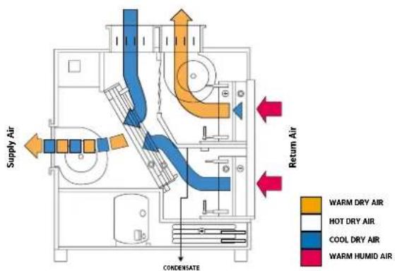
Delta models 4 and above provide an air conditioning facility to minimise the effects of solar gain from larger glazed areas or very high usage. Automatic damper and mode control.
Night set back

Air temperature set back control is incorporated as standard in all Delta units and controlled by a time clock. Pool hall air is dropped to a lower temperature for maximum economy. Air recirculation is maintained, dampers allow low fresh air flow.
1.2 HOW TO USE THE DELTA
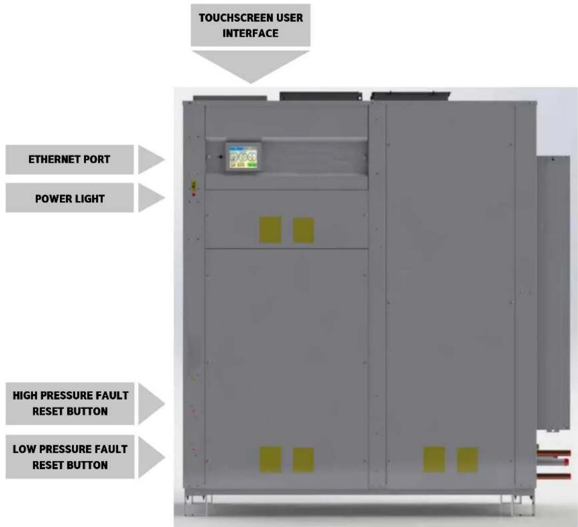
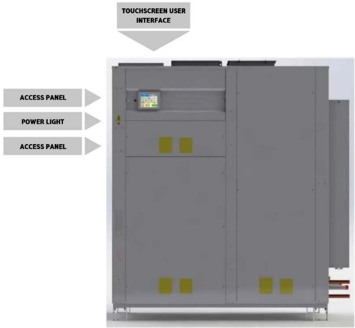
Power light – when illuminated red, power is connected to the Delta.
Caution – the Delta system remains powered and live. Ensure the Delta is isolated from the power supply before any servicing or electrical work commences. When unlit, power is disconnected but remote interfaces connected to the Delta from other systems may still be live.
Ethernet port – for connection to a local area network. (See page 53.)
Touchscreen user interface – display of operating condition and access to settings. (See page 9.)
High pressure fault reset button and low pressure fault reset button – reset buttons for LP/HP Fault. (See pages 11 and 19.)
1.3 TOUCHSCREEN USER INTERFACE
The Delta is controlled by an integral controller with a touchscreen user interface. All the settings of the Delta are available via the touchscreen.
Coloured buttons and parameters with a white background can be modified, except where locked by the User Security settings. Grey buttons and parameters with a grey background cannot be modified. (See page 23.)
If the screen is blank, touch once to activate.
Home screens
These two screens display current operating conditions and main controls. Functions on the home screens can be modified if allowed by the User Security Mode settings. (See page 23.)
First home screen
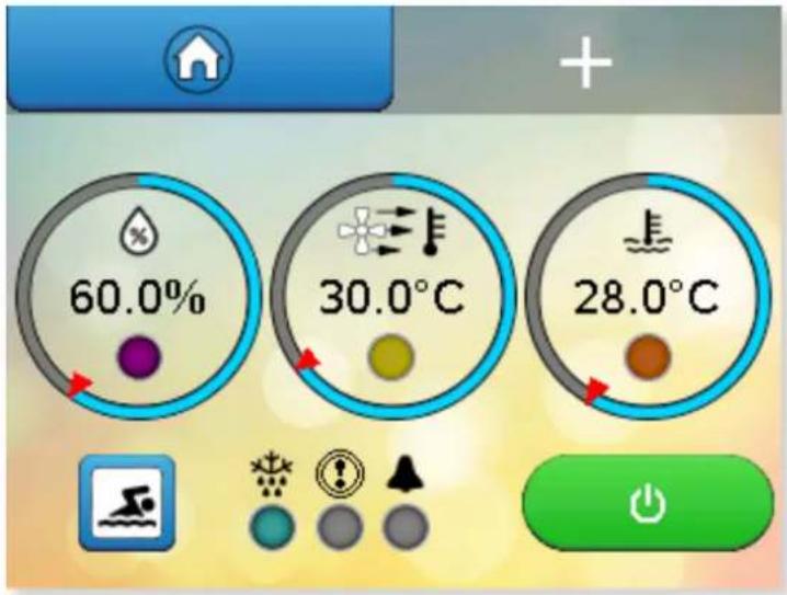
Pressing the + button shows the second home screen. Pressing the home button returns to the first home screen.
Second home screen

FIRST HOME SCREEN
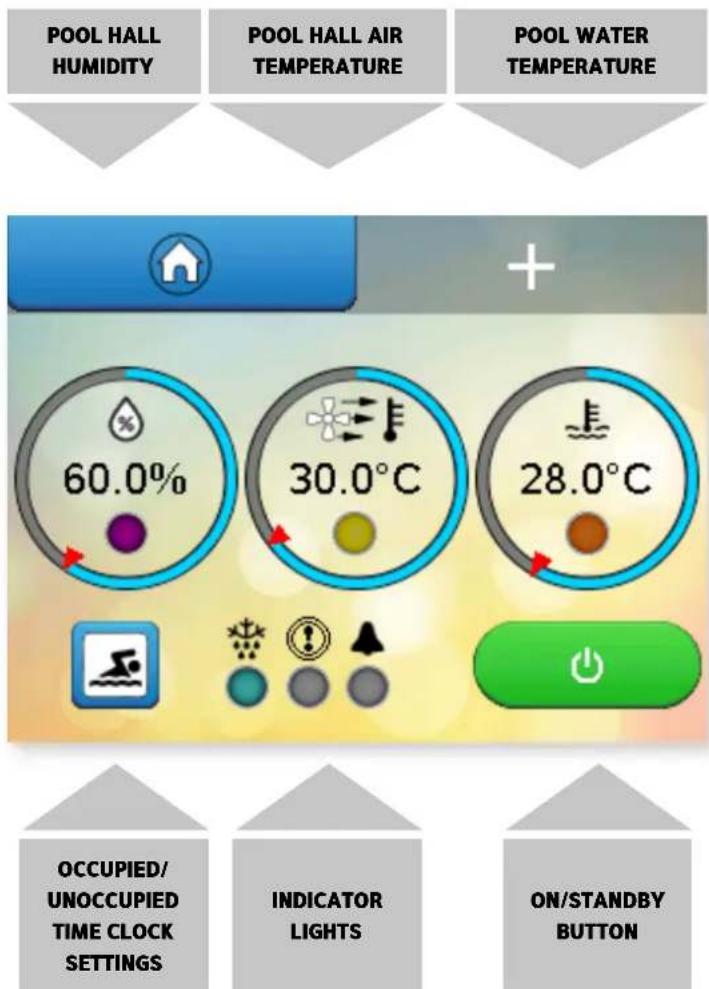
1. Pool hall relative humidity (%RH)
Number shows current measurement. Outer ring shows current measurement (blue bar) in relation to current setting (red arrow). Press the centre to change humidity setting.
Key to lights
Purple (flashing) – waiting for compressor delay timer to elapse.
Purple (solid) - dehumidification operating (compressor running).
Blue (solid) - air cooling mode operating (compressor running).
2. Pool hall air temperature (°C)
Number shows current measurement. Outer ring shows current measurement (blue bar) in relation to current Occupied mode setting (red arrow). Press the centre to change temperature setting.
Key to lights
Yellow (solid) – air heating via LPHW operating.
Blue (solid) - air cooling mode operating.
3. Pool water temperature (°C)
Number shows current measurement. Outer ring shows current measurement (blue bar) in relation to current setting (red arrow). Press the centre to change temperature setting.
Key to lights
Yellow (solid) – pool water heating via LPHW operating.
Orange (flashing) – water heating calling for the pool pump to run.
4. Swimming icon
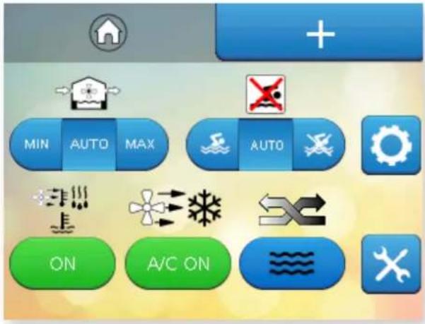
Press to access time clock settings. The swimming icon shows that the Delta is in the Occupied mode. A red cross indicates that the Delta is in Unoccupied mode.
Functions on the first home screen can be modified if allowed by the User Security Mode settings. (See page 23.)
LIGHTS AND STANDBY SWITCH

natural_image
Four icons on a yellow background: starburst, exclamation mark, warning triangle, and circle (no text or symbols)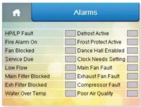


Indicator lights
Pressing this area when an alarm is active displays the "Alarms" screen.
Defrost light
Light blue (solid) – defrost is active. Defrosting is a normal function to remove ice from the heat recovery surfaces, which may be required when the pool hall air temperature drops below 20^ C.
Dark blue (solid) – frost protection is active. (See page 27.)
Light blue and dark blue (flashing) - defrost and frost protection are active.
Fault light
Red (solid) - fault with the refrigeration system.
Orange (solid) - fault with the main fan.
Yellow (solid) – fault with the exhaust fan.
Dark blue (solid) – no flow, fault with the pool pump.
Light blue (flashing) - pool water heat exchanger overheat protection.
Purple (solid) - fault with the compressor.
There can be more than one fault. All faults should be investigated. (See page 19.)
Alarm light
Red (solid) – fire alarm is active.
Pink (solid) - pool water heat exchanger overheat protection.
Orange (solid) - fan pressure alarm (if option fitted).
Yellow (solid) - filter dirty warning (if option fitted).
Dark blue (solid) – air quality sensor is overriding fresh air control (if option fitted).
Light blue (flashing) – 'Dance Hall Mode' is active. (See page 21.)
Purple (solid) - clock reset required.
Purple (solid) + 'S' – service is overdue. Contact the Dantherm Group to arrange servicing of the Delta.
Standby switch
Green and white - ON.
Delta is powered and operating according to the control system settings.
Red and white – user Standby.
Delta is powered but not operating. The Delta has been put into Standby via the user touchscreen. See caution below. To enable the Delta, press the red touchscreen button.
Orange and black – remote Standby.
Delta is powered but not operating. The Delta has been put into Standby via the remote On/Off control interface. See caution below. To enable the Delta, change the remote interface from Off to On.
Red and black – user and remote Standby.
Delta is powered but not operating. The Delta has been put into Standby via the user touchscreen AND the remote on/off control interface. See caution below. To enable the Delta, press the red touchscreen button AND change the remote interface from Off to On.
There is a five second delay before the Delta starts.
Caution: in all Standby modes, the Delta system remains powered and live. Ensure the Delta is isolated from the power supply before any servicing or electrical work commences. See power light on page 8.
Following a power interruption the Delta will either remain in Standby or attempt to restart automatically, according to the user setting. See page 29.
SECOND HOME SCREEN

flowchart
graph TD
    A["FRESH AIR SETTING BUTTONS"] --> B["+"]
    C["OCCUPIED/ UNOCCUPIED OVERRIDE"] --> B
    B --> D["MIN AUTO MAX AUTO GEAR"]
    B --> E["ON A/C ON"]
    B --> F["FUNCTION BUTTON"]
    B --> G["AIR- CONDITIONING BUTTON (DELTA 4 AND ABOVE ONLY)"]
    B --> H["HEAT RECOVERY PRIORITY SWITCH"]
    I["USER SETTINGS - PIN CODE REQUIRED"] --> J["SERVICE ENGINEER SETTINGS - PASSWORD PROTECTED"]
5. Fresh air setting
AUTO (recommended) allows automatic control of fresh air quantity according to control system settings. MIN allows experienced operators to override automatic fresh air control and force the minimum fresh air quantity. MAX allows experienced operators to override automatic fresh air control and force the maximum fresh air quantity.
6. Occupied/Unoccupied override
Normally set to AUTO, allowing the time clock to control the Occupied and Unoccupied periods of the Delta. The left-hand button sets the Delta into Occupied mode. The right-hand button sets the Delta into Unoccupied mode. If remote control of Occupied/Unoccupied is to be used, this control should be set to Unoccupied. (See page 14.)
7. User settings
Allows the user to change the settings of the Delta (user pin code required to access).
8. Function button
Green – ON. Enables the Delta to operate with full function. Red – OFF. Water heating only mode. Note: There is a 60 minute delay when water heating is required.
9. Air-conditioning mode button
Normally set to A/C ON, so the Delta provides air-conditioning when required. When switched to OFF, no air-conditioning will be allowed. Note: Fresh air will still be controlled irrespective of air conditioning mode selection.
10. Air/Water priority button
Switches the Delta between priority given to heating the pool water (recommended for most pools) or air.
11. Service engineer settings
These settings are for Dantherm Group service engineers and are password protected.
Functions on the second home screen can be modified if allowed by the User Security Mode settings. (See page 23.)

other
| Metric | Value (%) | |---|---| | Pool Hall Humidity (%RH) | 60.0 | | Pool Hall Air Temperature (°C) | 30.0 | | Pool Water Temperature (°C) | 28.0 |HUMIDITY AND TEMPERATURE SETTINGS
It is essential to control the pool hall conditions 24 hours per day and, once commissioned, your Delta should never be turned off if you are to avoid discomfort and/or expensive building damage due to humidity. It is a common mistake to believe that by turning the Delta off will save running costs. This is not true. Turning the Delta off turns off all the energy recovery it provides, and your swimming pool will cost you more to operate overall.
The energy usage and environment in a swimming pool are a delicate balance and your Delta has been selected to operate at very specific conditions. The most important principle in a swimming pool is the difference between the air and water temperatures. For both economy and comfort, it is good practice to keep the air temperature in the pool hall 1-2°C above the pool water temperature while the cover is removed (Occupied Mode). A normal humidity target in a pool hall is 60%RH. These settings should correspond to the original design parameters for the project. Unless other conditions were specifically requested at the time the system was designed, the most common conditions used in indoor pools are:
• Water temperature 28°C-30°C
• Air temperature 29°C-30°C
• Relative Humidity 60%RH
Changing the settings may result in high power consumption or less effective control of the environment. If you:
- Increase the water temperature – evaporation from the swimming pool water will increase, running costs will increase, and the likelihood of condensation will increase.
- Reduce the water temperature – evaporation from the swimming pool water will reduce, running costs will reduce.
- Increase the air temperature – evaporation from the swimming pool water will reduce, running costs usually reduce.
- Reduce the air temperature – evaporation from the swimming pool water will increase, running costs will increase, and the likelihood of discomfort and condensation will increase.
- Increase the humidity – running costs will reduce, but comfort will worsen, and the likelihood of condensation will increase.
- Reduce the humidity – running costs will increase, but may not improve comfort, nor reduce the likelihood of condensation.
If you do find it necessary to adjust settings, firstly ensure that the control system sensors are measuring accurately by using a calibrated thermometer and always maintain the air 1°C higher than water temperature. The settings for humidity, air temperature and pool temperature can be changed by touching the centre of the corresponding parameter. A keypad appears. (See page 10.)
Unless the Delta has been specifically chosen for the purpose, do not operate with the air temperature below the water temperature when the cover is removed.
The only exception is when a floating cover is in place on the pool (Unoccupied Mode).
POOL OCCUPIED SYMBOL
POOL UNOCCUPIED SYMBOL


natural_image
Symbol of a person crossing water with a red X (no text or numbers present)OCCUPIED AND UNOCCUPIED
Whenever a floating pool cover is in use, the cover suppresses evaporation and heat loss, so it is not necessary to maintain the air temperature higher than the pool water. Significant running cost reductions can be achieved by reducing the air temperature. Do not reduce the air temperature without a pool cover in place.
Normal operation, with the cover removed, is called Occupied Mode. Reduced air temperature operation, with the cover in place, is called Unoccupied Mode. It is expected that the pool will be covered during Unoccupied periods, to conserve energy and minimise evaporation. If Unoccupied Mode is used while the cover is removed, increased power consumption and loss of ideal conditions may result. The integral time clock on the control system allows fixed times to be set for when the cover will be in place. If you have an automatic pool cover, it may be possible to connect this to the Delta as described in section 3.8, to automatically set Occupied and Unoccupied modes when the cover is moved.
The Delta operates in either Occupied or Unoccupied Mode according to:
- User time period settings
- User override button
- Remote system connected to the interface terminals
In Occupied Mode, all functions operate according to User Settings.
In Unoccupied Mode, the following functions change:
- Pool hall air temperature setting reduced to the unoccupied temperature setting (sometimes called night set back). The pool hall will not be cooled
to this temperature, but if heating is required, it will only heat to this lower temperature setting.
- Refrigerated air-conditioning does not operate (Delta 4 upwards only). The economiser will operate, if enabled.
- Fresh air is reduced to minimum, unless the user fresh air setting or air quality sensor (if fitted) activate maximum fresh air.
- When water heating is required, there is a delay of 60 minutes (adjustable) in activating the pool pump and heating the water.
Going away for extended periods
Your Delta system, once commissioned, should never be turned off completely. Even a cold pool will allow moisture to evaporate into the environment and if this is not dealt with expensive building damage may follow. If you go away for extended periods or wish to take the pool out of commission, then you should follow the following procedure:
Use a good swimming pool cover on the pool to minimise evaporation.
- Set the water temperature at 10^ C
- Set the air temperature to 12-15°C
• Leave the humidity setting at 60-65%RH
• Leave the time clock setting in Unoccupied Mode
These settings will minimise energy usage whilst providing maximum protection for your building.
1.4 DATA ENTRY
Coloured buttons and parameters with a white background can be modified, except where locked by the User Security settings. Grey buttons and parameters with a grey background cannot be modified.
To change parameters with a white background, press the parameter. A keypad appears for number entry – an alphabet appears for text entry.
The keypad for entering numeric parameters is shown below. The parameter to be modified is shown at the top. The allowable range that the parameter can be changed between is shown underneath.
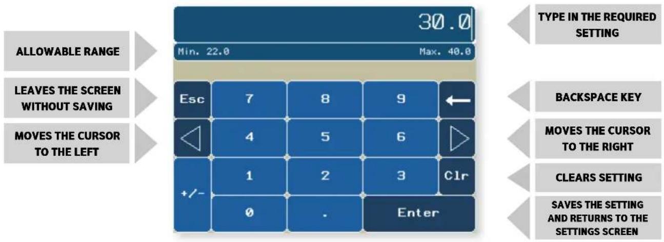
SECURITY MODE
If Security Mode is enabled (see p23) some functions may not be accessible from the home screens. Functions that are not accessible are shown with hashed lines. In the examples shown below all functions have restricted access apart from the Occupied/Unoccupied override.

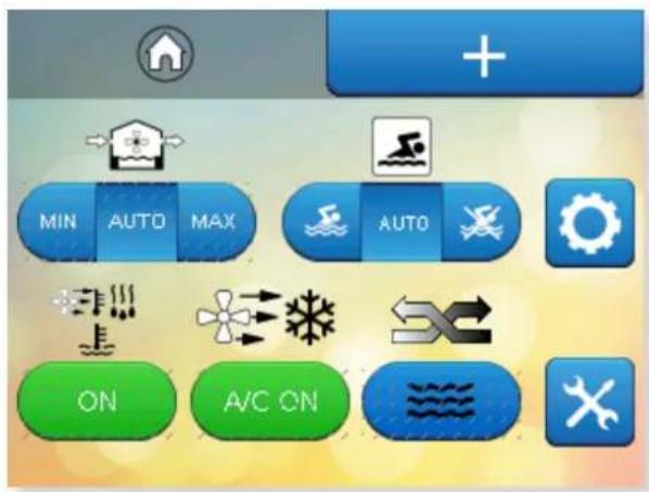
2.0 USER SETTINGS
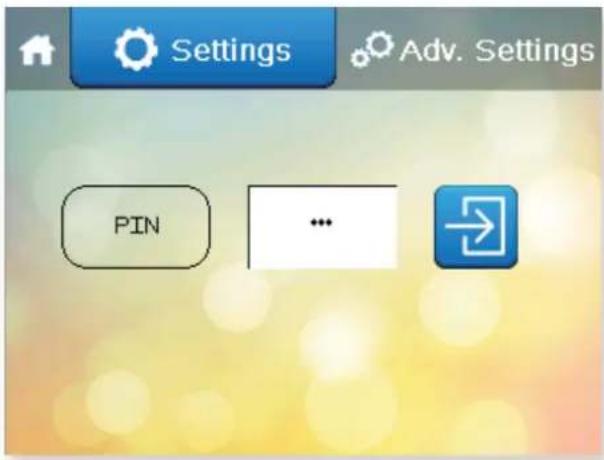
The main User Settings screens are protected by a PIN code. User Settings can be accessed by pressing the cog button on the second Home screen.

INSERT THE PIN AND PRESS THE ARROW
The default PIN for accessing the User Settings is 6016.
The Dantherm Group recommend this is changed.
Security options and record of PIN. (See page 23.)

Settings

Controller Clock Occupied/Unoccupied periods Alarms Set Points and Switches


Dance Hall Mode Language User Security Data Monitoring


CONTROLLER CLOCK
Press this button on the Settings menu.

Arrow icon
Return to
User Settings

Home icon
Return to
Home screen


PRESS SET CLOCK
To change the date or time, press the white box with the number to be changed. Press Set Clock when the date and time are correct.
Press the Arrow to return to the User Settings screen or if nothing else needs to be changed, press Home to return to the Home screen.
Once the time and date have been set this should not need to be done again as long as the Delta is On or in Standby. The clock has a battery reserve fitted which, when charged, has an operating time of three days so that isolating the Delta unit for short periods will not reset the clock. It may be necessary to set the clock if the Delta is isolated from power or if there is an interruption to the power supply which lasts longer than three days.

This button is red when daylight saving is disabled and green when daylight saving is enabled.
Press the button to manually toggle between enabled and disabled.
Default factory settings are UK daylight saving periods and will change automatically on the dates set in this screen. Where the daylight saving times and dates are different to those shown, they can be changed here.
Press the Arrow to return to the User Settings screen or if nothing else needs to be changed, press Home to return to the Home screen.

TIME CLOCK
Press this button on the Settings menu.

Home icon
Return to Home screen
Press the left side of the colon to change the hour setting.
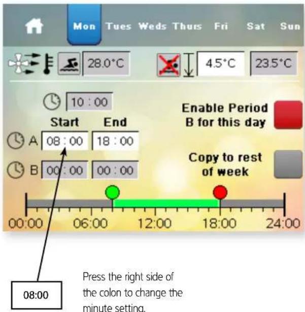
If a second occupied period is required enable this button. Times in the second period can be entered in B.
The times for the rest of the week can be copied by pressing this button.
This screen can also be accessed from the first Home screen if the User Security settings are set to allow access.
When one of the time settings is touched, the keypad appears to allow the parameter to be changed. Any time with a white background can be changed.
There are two periods per day, A and B. Days can be set individually, or copied to the whole week. If A and B periods overlap, priority is given the Occupied period. If one Occupied period is required, period B can be disabled.
The current Occupied air temperature and the Unoccupied air temperature settings are shown. The Unoccupied setting is set as the difference between the two, which can be changed. In the example above, the Occupied air temperature setting is 28.0°C and the Unoccupied air temperature setting is 4.5°C below that, 23.5°C. The minimum night set back temperature controlled by the Delta is 22°C. This means that the greatest difference allowed is 6°C.
Press the Home button to return to the User Settings screen.

ALARMS
Press this button on the Settings menu.

Arrow icon
Return to
User Settings

Home icon
Return to
Home screen

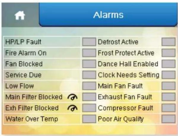
The Alarms screen displays warnings or faults with the Delta, indicated by a red highlight. The example above indicates that there is a problem with the pool water flow rate that should be investigated.
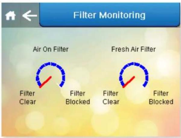
The Main Filter Blocked and Exhaust Filter Blocked alarm text is always shown, but will only function if the optional filter monitoring sensors are fitted in the Delta. When fitted, gauge symbols are shown beside the text for these alarms (see below). When shown, this area can be pressed to access a visualisation of the sensor measurements.

SET POINTS AND SWITCHES
Press this button on the Settings menu.

Arrow icon
Return to
User Settings

Home icon
Return to
Home screen
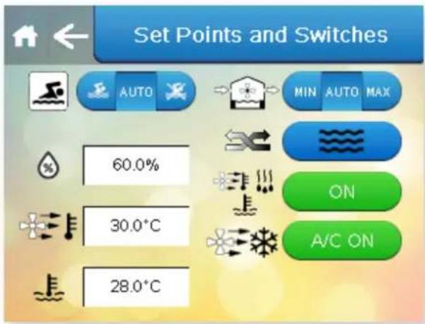
This screen duplicates settings on the Home screens. If functions on the Home screens are disabled by the User Security settings, they may be accessed here. Press the Arrow to return to the User Settings screen or if nothing else needs to be changed press Home to return to the Home screen.

DANCE HALL MODE
Press this button on the Settings menu.

Arrow icon
Return to
User Settings

Home icon
Return to
Home screen

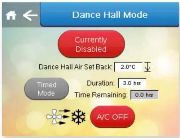


Dance Hall Mode is designed to allow a different air temperature to be used if the pool hall is to be used for a function other than swimming. Water heating and humidity control is deactivated. Air-conditioning is enabled or disabled according to the setting of the A/C ON/OFF button.
Dance Hall Mode can be enabled or disabled by pressing the Currently Enabled/Currently Disabled button to toggle between two.
Dance Hall Mode can be enabled in Constant Mode or Timed Mode. Pressing the Constant Mode/Timed Mode button toggles between the two. In Timed Mode, the maximum timer duration is nine hours. In Constant Mode, the Delta remains in Dance Hall Mode until disabled by the user. Dance Hall Mode is not intended to be used for a long period. If Dance Hall Mode is enabled for a long time, the pool water temperature may fall outside the normal operating range.
The dance hall air temperature setting is shown. The Delta controls the air to a temperature below the Occupied air temperature setting. In the example above, if the Occupied air temperature setting is 28^ C, the Dance Hall temperature is 24^ C (= 28 - 4).
The A/C ON/OFF button determines whether the Delta actively tries to cool the pool hall. Due to the heat recovery properties of the Delta system, use of the air-conditioning function in Dance Hall Mode may result in the pool water being heated above the user setting.
Press the Arrow to return to the User Settings screen or if nothing else needs to be changed press Home to return to the Home screen.

LANGUAGE
Press this button on the Settings menu.

Arrow icon
Return to
User Settings

Home icon
Return to
Home screen

The available languages are shown on this screen and can be selected by pressing the button corresponding to the required language.

USER SECURITY
Press this button on the Settings menu.

Arrow icon
Return to
User Settings

Home icon
Return to
Home screen

Toggles between Password
Enabled and Password Disabled

If the User PIN needs to be changed, it can be changed here. The factory default User PIN is 6016. If the PIN is changed, write it in the box on the right and keep this manual in a safe place.
The User PIN can be enabled or disabled. Pressing the Password Enabled/Password Disabled button toggles between to two. When disabled, the User Settings screen can be accessed without the User PIN.
USER PIN:

Arrow icon
Return to
User Settings

Home icon
Return to
Home screen

flowchart
graph TD
    A["User Pass"] --> B["Security Mode"]
    C["Webgate Pass"] --> D["Security Mode Enabled"]
    B --> E["RH Set Point"]
    B --> F["Air Temp Set Point"]
    B --> G["Water Temp Set Point"]
    B --> H["Night Setback Schedule"]
    B --> I["Forced Occupation"]
    B --> J["Operation Switch"]
    B --> K["Damper Position"]
    B --> L["Priority Switch"]
    B --> M["Air Cool Switch"]
Toggles between
Security Mode Enabled and Security Mode Disabled
Security Mode Disabled
When Security Mode is enabled the buttons shown on the screen can be toggled between grey and orange. Settings in grey can be modified directly from the Home screens. Settings in orange are disabled on the Home screens and must be accessed through the User Settings.
When Security Mode is disabled, all home screen functions are set to grey and can be modified on the Home screens.
Press the Arrow to return to the User Settings screen or if nothing else needs to be changed, press Home to return to the Home screen.
CHANGE WEBGATE PASS
Press the button on the right.

Arrow icon
Return to
User Settings

Home icon
Return to
Home screen


Press to confirm current password and proceed to the change password screen
The factory default Webgate password is DefaultPass.
For security reasons the Dantherm Group recommend that this password is changed.
If the password is changed, write it in the box below and keep this manual in a safe place.
If the password is forgotten, it can only be reset during a visit by a service engineer.
Press the Arrow to return to the User Security screen or if nothing else needs to be changed press Home to return to the Home screen.
WEBGATE PASSWORD:

Arrow icon
Return to
User Settings

Home icon
Return to
Home screen

Button performs same function as Home button

DATA MONITORING
Press this button on the Settings menu.

Arrow icon
Return to
User Settings

Home icon
Return to
Home screen
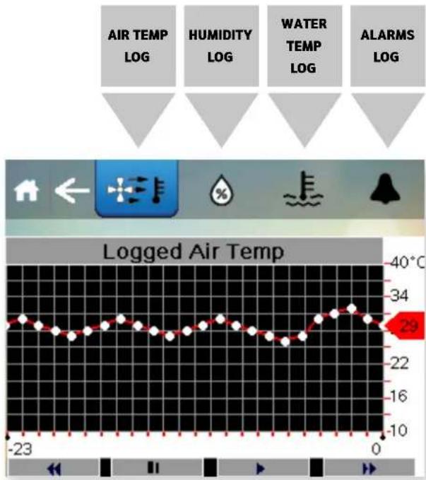
line
| Time (s) | Logged Air Temp (°C) | |---|---| | -23 | 29 | | 0 | 10 |Pressing the buttons brings up a graph of the selected parameter. Choose from Air temperature, Humidity, Water temperature and Alarms. The display is marked up in hours and shows the past 72 hours of activity.

Arrow icon
Return to
User Settings

Home icon
Return to
Home screen

Press the Arrow to return to the User Settings screen or press Home to return to the Home screen.
2.1 ADVANCED SETTINGS
Press this button on the Settings menu.
WARNING
ACCESSING THE ADVANCED SETTINGS BY PUTTING IN THE ONE TIME PASSWORD TAKES YOU INTO PARAMETERS THAT MAY FUNDAMENTALLY CHANGE THE WAY THE DELTA BEHAVES. A SERVICE VISIT MAY BE NECESSARY IF THE PARAMETERS ARE CHANGED INCORRECTLY.
The one-time PIN for accessing these screens is 1842. Once this PIN has been entered once, you will not be prompted for this password in the future.

The Advanced Settings screen appears.

Advanced Settings

Offsets Customer Timers Screen Settings Reset to Factory settings


IP Address BMS Settings More Options


OFFSETS
Press this button on the Advanced Settings menu.

Arrow icon
Return to
User Settings

Home icon
Return to
Home screen

Offsets
The actual conditions in the pool may be slightly different to the conditions detected and shown on the display. If this is due to sensor calibration, a correction can be entered here to improve accuracy. For example, the Delta displays a pool temperature of 27.5°C, and a calibrated thermometer measures 28.0°C. In this instance an offset of +0.5°C can be applied to calibrate the sensor.
The single arrows change the offset in 0.1 increments.
The double arrows change the offsets in 1.0 increments.
Frost Protection
When the outdoor temperature is 6^ C or lower and the Frost Protection function is enabled, the amount of fresh air allowed by the dampers can be adjusted by increasing or decreasing the percentage of fresh air.
The arrows change the offset in 5% increments.
Press the Arrow to return to the Advanced Setting screen or if nothing else needs to be changed press Home to return to the Home screen.
CUSTOMER TIMERS
Press this button on the Advanced Settings menu.

Arrow icon
Return to
User Settings

Home icon
Return to
Home screen

The Delta is connected directly to the pool water circuit. If the pool water pump is on a timer, it can be started outside the normal "pump on" times by the Delta, using interface terminals (see Installation section). When the pool water pump is off, the Delta cannot measure the pool temperature, so the control system will respond to a water heating demand by starting the pool water pump to check the demand is accurate.
Timers delay this response, as follows (factory defaults).
Occupied mode – no delay
Unoccupied mode - 1 hour
The delay timers can be edited from this screen. The sum of the Occupied and Unoccupied timers cannot be more than 23 hours. The pool pump will always be started with no delay in response to a heat recovery requirement.
Please refer to the Occupied and Unoccupied periods before changing these timers. If these delays are set longer than the Occupied and Unoccupied periods, the pool may not be heated sufficiently.
Defrost Off Delay timer – when the Delta control system ends a defrost cycle, the heat pump will restart after the usual delay time. If an additional delay to defrost ending is required, this can be entered here. This delay allows extra time for defrost. Your Dantherm Group service engineer will advise if this is necessary.
Pool Pump Off Delay - determines how long the pool pump demand control (terminals 8/9, see page 50) will continue to run the pool pump to cool the heat exchangers after a heating demand ends. The default settings is 120 seconds.

SCREEN SETTINGS
Press this button on the Advanced Settings menu.

Arrow icon
Return to
User Settings

Home icon
Return to
Home screen

The screen settings can be changed here.
Menu Timeout – the length of time after which the display to automatically return to the Home screen after the last screen press.
Backlight Sleep – the length of time after which the display switches off after the last screen press. Touching the screen will restore the display.
Brightness – can be increased or decreased.
Colour Blind Mode – can be enabled to improve colour contrast. Press the Arrow to return to the Advanced Settings screen or if nothing else needs to be changed press Home to return to the Home screen.
The "Reset Standby Switch on Power Loss" button determines what happens when power is interrupted.
When set to ON the Delta restarts in Standby mode when power is reconnected, and does not function until the On/Standby button is pressed.
When set to OFF, the Delta tries to restart all functions automatically when power is reconnected. During a unplanned power cut, safety devices may activate to protect the Delta system and may require resetting by the user.
Screen Configuration settings button – allows access to advanced screen configuration settings. The touchscreen can be recalibrated here if it does not register finger or stylus touches in the correct position. Other settings should be left as default unless changes are advised by the Dantherm Group.

FACTORY RESET
Press this button on the Advanced Settings menu.

Arrow icon
Return to
User Settings

Home icon
Return to
Home screen
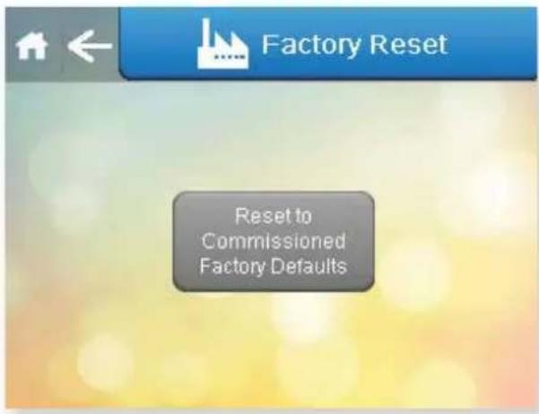
If the settings have been changed in a way that makes the Delta behave in an unusual way, the original commissioned settings can restored by pressing the Reset to Commissioned Factory Defaults button on this screen. After this has been pressed a confirmation appears, pressing again completes the reset.
Press the Arrow to return to the Advanced Setting screen or if nothing else needs to be changed press Home to return to the Home screen.

NETWORK SETTINGS
Press this button on the Advanced Settings menu.

Arrow icon
Return to
User Settings

Home icon
Return to
Home screen
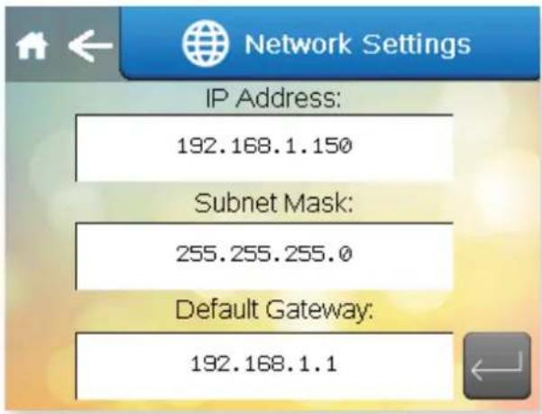
Insert the correct information, data shown here is an example.
This screen contains settings related to remote access by an Android/iOS device or ActiveX browser. (See Remote Access to the Delta Touchscreen on page 34.) When accessing this screen on remote access, the IP address shown will be that of the access device, and it is not possible to view/change the Delta IP address. The Delta IP address can only be changed from the touchscreen.
Press the Arrow to return to the Advanced Setting screen or if nothing else needs to be changed press Home to return to the Home screen.

BMS SETTINGS
Press this button on the Advanced Settings menu.

Arrow icon
Return to
User Settings

Home icon
Return to
Home screen

This screen contains settings related to BMS connectivity when using Modbus/RTU and BACnet MS/TP through the spare RS485 port. The factory default settings are shown. If connecting using BACnet/IP, see the PLC Ethernet Settings screen on page 32.
Slave Address. Can be set from 0 to 255.
Baud Rate. Can be set from 0 to 5, corresponding to:
| 0 9600 | |
| 1 19200 | |
| 2 38400 | |
| 3 57600 | |
| 4 76800 | |
| 5 115200 |
Protocol Used. Can be set from 2 to 4, corresponding to:
| 2 uNET | |
| 3 Modbus/RTU | |
| 4 BACnet MS/TP |
Data Bit. Always set to 8. Included for information only, to configure own software if needed.
Parity Bit. Can be set from 0 to 2, corresponding to:
| 0 Null | |
| 1 Odd | |
| 2 Even |
Stop Bit. Can be set from 1 to 2.
BACnet/IP Port – can be set from 0 to 65535.0 corresponds to the default port 47808.65535 corresponds to BACnet stack running only on PLC side.
After changing any of the above settings, restart the PLC/Delta to save and apply the new settings.
For Modbus Variable list and BACnet Object list please consult the Dantherm Group.
PLC ETHERNET SETTINGS
Press the button on the right.

Arrow icon
Return to
User Settings

Home icon
Return to
Home screen

This screen contains settings related to BMS connectivity using BACnet/IP through the Ethernet port on the PLC. The factory default settings are shown. If connecting using Modbus/RTU or BACnet MS/TP, see the BMS Settings screen on page 31.
Enable DHCP. This button toggles between DHCP enabled or disabled.
IP Address, Subnet Mask, Default Gateway, Primary and Secondary DNS – all fields can be set from 0 to 255.
HTTP Port. Can be set from 0 to 65535. 0 corresponds to default port 80.
TCP/IP Port Can be set from 0 to 65535. Default is 502.
After changing any of the above settings, restart the PLC/Delta to save and apply the new settings.
For Modbus Variable list and BACnet Object list please consult the Dantherm Group.

MORE OPTIONS
Press this button on the Advanced Settings menu.

Arrow icon
Return to
User Settings

Home icon
Return to
Home screen

Button toggles between YES and NO
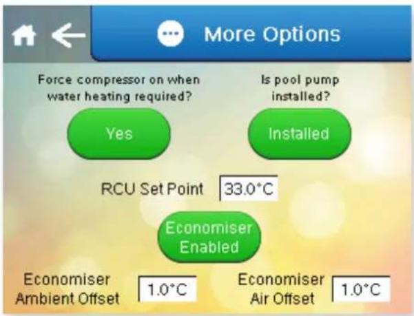

Button toggles between Economiser Enabled and Economiser Disabled

Button toggles between Installed and Not Installed
The "Force compressor on when water heating is required" button toggles between Yes and No. When set to Yes, the heat pump will be turned on to provide water heating. This option only functions when priority is set to water.
The "Is Pool Pump Installed" button toggles between Installed and Not Installed. If the Delta is not connected to pool water, this should be set to Not Installed. This will prevent false alarms relating the pool water, and disable functions that require the pool water to be connected. Pool water heat recovery, LPHW heating and air-conditioning functions will be disabled.
The RCU set point is used when the Delta is built to be connected to RCUs. Check with the Dantherm Group for additional information if this option is fitted.
The Economiser allows for free cooling using fresh air to cool the pool hall rather than refrigerated air-conditioning using the heat pump.
For the Economiser to work two conditions need to be met.
- The outdoor air temperature must be lower than the pool hall air temperature. This difference is set by the Economiser Ambient Offset in the screen shown above.
- The pool hall air temperature needs to be higher than the user temperature setting, but below the temperature that air-conditioning turns on. This difference is set by the Economiser Air Offset in the screen shown above.
The Delta control system measures the outdoor air temperature using a sensor measuring the incoming fresh air temperature. The Economiser can be enabled/disabled using the Economiser Enabled/Economiser Disabled button to toggle between the two. When enabled, if the above conditions are met, the Delta will increase the fresh air quantity to reduce the pool hall temperature.
Press the Arrow to return to the Advanced Setting screen or if nothing else needs to be changed press Home to return to the Home screen.
2.2 REMOTE ACCESS TO THE DELTA TOUCHSCREEN

natural_image
Illustration of a set of electronic devices including a desktop computer, laptop, and smartphone (no text or symbols)The Delta can be controlled remotely either through a mobile device using a third-party Android/iOS app, or using a computer with a web browser that can run Active X.
The Delta touchscreen must be connected to a LAN (local area network), accessible to the device or computer to be used.
Local Area Network Connection
The RJ45 Ethernet port on the front panel may be used. Alternatively the connection may be made directly to the RJ45 Ethernet port on the back of the touchscreen, after disconnecting the front panel extension cable.
The default network IP address for the Delta is 192.168.1.150, but may be changed as required (see section 2.1 Network setting).
If the Delta is only to be accessed by devices connected to the same network, no further network setup is necessary. If the Delta is to be accessed from devices NOT connected to the same network, it is necessary to set port forwarding to the network IP address of the Delta.
Ports to be forwarded
80
6000
6002
If the Delta is to be accessed from devices NOT connected to the same network, a static public IP address for the network is recommended. If your ISP (internet service provider) is not able to provide a static IP address, third party solutions are available to provide a static IP address, which may involve a cost.
Once set up, the Delta may be accessed from an ActiveX enabled browser such as Internet Explorer, or a mobile device using the Vijeo Design' Air app.
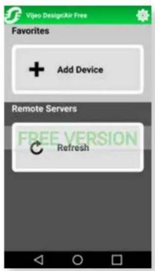

Using an Android/iOS mobile device
The Delta touchscreen can be controlled by a mobile device. To access the Delta by a mobile device, the Vijeo Design'Air app must be installed on the device. A free version is available with restricted usage time. A paid version is available with unlimited access. The setup procedure depends how the remote access is to be used.
If the Delta is ONLY to be accessed when the device is connected to the SAME network as the Delta:
After installing the app, open it and select "Add Device". In the fields that appear enter a name (e.g. Delta), the network IP address of the Delta (see section 2.1 Network setting) and leave the port number as the default setting. From now on the Delta can be controlled from your mobile device by selecting it from "Favourites". Read the disclaimer carefully before accepting the terms and conditions of the app. The box needs to be ticked before the OK button can be pressed.
When the login window appears, login with the username "Webgate" and password. Both are case sensitive. The default password is "DefaultPass". For security reasons the Dantherm Group recommend this password is changed. (See section 2.1 User Security settings.)
If the Delta is to be accessed when the device could be anywhere:
First obtain the public IP address of the network the Delta is connected to using another device that is connected to the same network. Search for "What is my IP" in a search engine and make a note. Ensure port forwarding has been set on the router as mentioned on p34.
It is recommended to perform the app setup when the device is NOT connected to the same network as the Delta (turn off wi-fi or leave the network area). After installing the app, open it and select "Add Device". In the fields that appear enter a name, e.g. "Delta", the public IP address of the network and leave the port number as the default setting. From now on the Delta can be controlled from your mobile device by selecting it from "Favourites". Read the disclaimer carefully before accepting the terms and conditions of the app. The box needs to be ticked before the OK button can be pressed.
When the login window appears, login with the username "Webgate" and password. Both are case sensitive. The default password is "DefaultPass". For security reasons the Dantherm Group recommend this password is changed. (See section 2.1 User Security settings.)
Depending on the router specification, this these settings may also work whilst the device is connected to the same network as the Delta. This can be tested with the device connected to the same network. If it does not work, it will be necessary to add a second device to the app, e.g. "Delta home", using the network IP address (see above). Use the "Delta" device when not connected to the same network and "Delta home" device when connected to the same network.
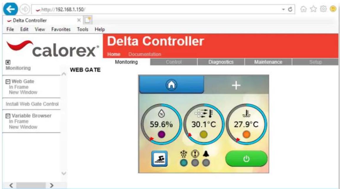
Using an ActiveX web browser on a networked computer
To access the Delta by a networked computer, a browser that can run ActiveX is required. This function has been designed and tested to work with Internet Explorer. Other browsers are not formally supported.
For first time setup instructions, see right.
Once the computer and browser have been setup, screen mirroring can be accessed as follows:
If the Delta is ONLY to be accessed when the computer is connected to the SAME network as the Delta:
In your browser address bar, enter the Delta network IP address (default address 192.168.1.150) and press Enter or click Go.
If the Delta is to be accessed when the device could be anywhere:
First obtain the public IP address of the network the Delta is connected to using a computer that is connected to the same network. Search for "What is my IP" in a search engine and make a note. Ensure port forwarding has been set on the router as mentioned on p34.
It is recommended to test this when the computer is NOT connected to the same network as the Delta (turn off wi-fi or leave the network area). In your browser address bar, enter the public IP address of the network and press Enter or click Go.
Depending on the router specification, the public IP address may also work whilst the device is connected to the same network as the Delta. If it does not work, it will be necessary to use the Delta network IP address when the computer is connected to the same network.
ActiveX browser first time set up procedure
Follow the user access instructions on the left, with the following additional steps.
When prompted, install the Vijeo-Webgate Control. This is stored on the Delta controller, so internet access is not necessary. When prompted, allow Windows to install.
When prompted, the Delta IP address must be added to the browser Trusted Sites list. This is accessible on the Internet Explorer menu – Tools > Internet Options > Security > Trusted Sites > Sites > Add. It may be necessary to uncheck the "Require server verification" box to complete this action. This may be rechecked after the site has been added. If the IP address of the Delta is changed, the new IP address must be added to the Trusted Sites list.
When prompted, install the Active X runtime. This is stored on the Delta controller, so internet access is not necessary. When prompted, allow Windows to install. If flagged by your anti-virus or firewall software, the runtime files should be allowed access.
The browser should be restarted and standard user access instructions can then be followed.
Whichever method is used, when the Delta Controller appears:
- Click "Monitoring" in menu bar of the main window.
- Click "In Frame" or "New Window" from under Webgate in the left-hand menu.
- When the login window appears, login with the username "Webgate" and password. Both are case sensitive. The default password is "DefaultPass". For security reasons the Dantherm Group recommend this password is changed. (See 2.1 User Security settings.)
- Read the warning message carefully and click "Continue to Main Screen." The Delta can be controlled with a mouse as if using the integral touchscreen. Numbers and text can be entered with a keyboard.
- Note that some settings can not be changed through remote access, e.g. Network Settings and Webgate Password.
3.0 INSTALLATION
Installation summary
The Delta is a fully packaged system, supplied as a single piece, ready for positioning and connection to services. The Delta is designed to be installed in an internal plant room. The Delta is suitable for operating in plantroom temperatures from 0^ C to +40^ C.
Unloading and unpacking
On arrival, check the condition of the Delta and that the controls, duct connections and pipe connections are in the positions ordered. Report any concerns to your supplier prior to installation.
Items included with Delta
- User/Installation manual
• Warranty registration card - Touchscreen removal adapter
• Floor duct adapter (bottom outlet models only) - Pool pipework 1" to 1½" adapters (Delta 4-8 models only)
Positioning
The Delta must be kept upright at all times. The cabinet is designed to be supported from the bottom. If lifting with a crane, spreader bars should be used to protect the top of the cabinet from crushing.
Siting
Ensure sufficient access to controls, service access panels and connections for users and service engineers. Due consideration should be given to Health and Safety when designing access for users and service engineers.
Summary of connections and services
Ductwork
• Return air, from pool hall
• Supply air, to pool hall
• Exhaust air, to atmosphere
• Fresh air, from atmosphere
Plumbing
• Pool water circuit, flow and return
• LPHW system, flow and return
- Condensate drain
Electrical
• Power supply
Remote interfaces (if required)
- Terminals
• Network connection
• BMS connections
After installation
• Pre-commissioning checklist
- Initial start-up
- Commissioning
- Operator handover
Ongoing maintenance
The Delta has been designed to operate continuously over a long service life. Preventative maintenance is essential to keep the system operating effectively and efficiently.
3.1 SITING, MACHINE LOCATION
"EF" CONFIGURATION

"ER" CONFIGURATION
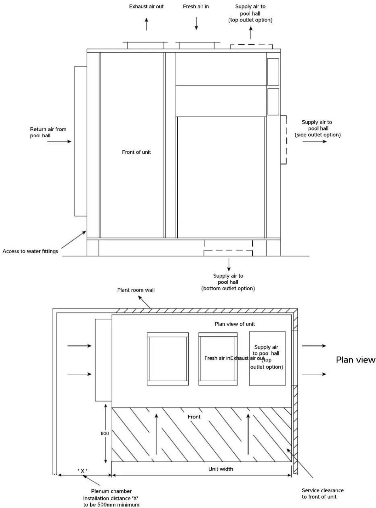
3.2 AIR FLOW (POOL HALL AIR)
"EF"
CONFIGURATION

"ER"
CONFIGURATION

3.3 FRESH AIR AND EXHAUST AIR

Notes
- Ensure duct work pressure drop including all inlet/outlet grilles does not exceed resistance given in data sheet, section 5.0.
-
Every effort must be made to prevent re-circulation of exhaust air back into the fresh air inlet.
-
Ensure fresh air inlet does not become blocked by debris (leaves, grass cuttings, etc).
- If unit is located in a plant room at pool hall air temperatures any ambient air ducting must be heavily insulated.
- Ensure flexible couplings are used to seal the ambient suction and discharge adapters from each other to prevent cold air from entering the plant room.
3.4 PLUMBING INSTALLATION
Pool water
a. The Delta must be connected into the pool filtration water circuit, after the pump and filter. If an existing heater is being retained, then the Delta should be connected upstream of the existing heater (see following schematics), or in parallel.
b. The Delta has plastic stubs (solvent weld) for connecting the pool water flow and return. On Delta 1 to 8 these stubs are 1" diameter. On Delta 10 to 16 these stubs are 1½".
c. Suitable breakable couplings, isolation, and drain down valves should be installed in the pool water flow and return pipes.
d. The Delta may, on small pools, take the full flow rate of the pool filtration system. On larger pools, or if the pool flow rate does not match, a bypass or separate auxiliary pump may be necessary. This method can also be used to reduce energy consumption, by the installation of a two speed or auxiliary pump by-passing the main pump/filter to satisfy pool water heating and dehumidification without the need for the main pump to be running. Further savings on both the above methods can be made by utilizing the standard feature on all Delta units to control the main or auxiliary pumps. (See page 51.)
e. When the pipe work installation is complete the circulating pump(s) should be switched on and the system checked for leaks. Check the filter gauge to see that there is not excessive back pressure.
f. A flow meter should be fitted (or pressure gauges).
Condensate drain
a. The condensate drip tray at the base of the Delta collects the water removed by the dehumidification process. Ensure the Delta is placed on a level plinth so that the condensate can run away and not overflow the edges of the drip tray inside the machine.
b. All Delta models have a 34 " BSPM threaded condensate drain connection. The drain pipe should be run away with the adequate fall to waste i.e. 12 " per ft minimum. DO NOT fit a trap as it is a standard fitting inside the unit. An air break or tun dish should be incorporated to prevent back flow of foul water and smells. (See Fig 3.1 on page 44.)
LPHW plumbing
a. Delta 1 and 2 have 28mm copper stubs. Delta 4, 6 and 8 with standard LPHW have 28mm copper stubs. Delta 4, 6 and 8 with upgraded LPHW have 35mm copper stubs. Delta 10 and 12 have 35mm copper stubs. Delta 14 and 16 with standard LPHW have 1½" BSPM. Delta 14 and 16 with upgraded LPHW have 2" BSPM..
b. Suitable breakable couplings, isolation and drain down valves should be installed in the boiler water flow/return pipes local to the Delta unit.
c. A mixing valve and/or bypass may be required to maintain a minimum boiler return temperature and/or keep a constant load to the boiler pump. Refer to the boiler manufacturers instructions before designing the pipe work system.
d. If boiler and water pump is not controlled by Delta then a boiler bypass will be required.
e. A flow meter should be fitted (or pressure gauges).
f. A filter or "boiler buddy" should be added to the pipe work to help keep the heat exchangers in the Delta free from blockages.
Important general points
a. Do not route water pipes across service access panels, filter access or duct connections.
b. The water circuits to and from the Delta should be capable of maintaining water flow within the specified limits. (See section 5.0 DATA SHEET on page 61.)
c. All pipe work must be adequately supported with allowance for expansion and contraction especially with regard to the plastic pipe work.
d. It is recommended that when installing water systems the last connections to be made should be adjacent to the Delta to avoid undue stresses on the internal pipework.
e. All pool Purifying Devices and Chemical Injection Systems must be fitted down stream of the Delta unit with a non-return valve to prevent concentrated chemicals back feeding into the heat exchangers.
The practice of dosing chemicals direct into the Skimmer Basket which results in concentrated corrosive liquids passing over vulnerable metal components must not be allowed.
f. Water quality must be maintained not only relating to solids, etc. but for pH between 7.4 ± 0.4 , (and if pool water is saline at a maximum concentration of 3% wt/wt). See 8.0 WARRANTY CONDITIONS for total list of water quality limits.
Determining water flow
a. Flow Meter Method (see Fig 3)
Ensure isolation valves 'A' and 'B' and bypass valve 'C' are fully open. Slowly close down bypass valve 'C' until correct flow rate (See section 5.0 DATA SHEET on page 6.1) is shown on the flow meter. Remove handle and lock off valve 'C'.
b. Differential Pressure Method (see Fig 3)
By simply installing two filter pressure indicating gauges, one each on the inlet and outlet of the heat pump, and a locking type gate bypass valve in the bypass line, the flow rate through the heat pump can be accurately determined by the difference in the readings of the gauges. This pressure drop is proportional to flow. Flow rate should be set at the maximum differential with a clean filter if fitted. This differential pressure will drop as the filter becomes dirty. Provided the filter is cleaned before the minimum differential is reached (which would normally be the case with a well managed system) then no problems should be encountered.
Setting up the differential
When installation is complete, the procedure for setting the flow rate through the heat pump using two gauges is as follows:
- With the heat pump switched off ensure isolation valves 'A', 'B' and bypass valve 'C' are fully open.
- Note the System Pressure on both gauges – they should read the same, but due to manufacturing tolerances they may be different.
- Switch on water circulating pump.
For example; with a water System Pressure of 5mhd the gauge on the inlet may read 5 and the outlet gauge 5.5 therefore there is a STATIC ERROR DIFFERENCE of 0.5mhd.
-
Gradually close the bypass valve 'C' until there is a difference in pressure between the two gauges that is equal to the required pressure drop (See section 5.0 DATA SHEET on page 6.1) observing any static error on the gauges before beginning this process.
-
Lock the bypass valve, or render it tamper proof, when correct setting is achieved.
-
See section 5.0 DATA SHEET on page 6.1 for correct water pressure drop.
Fig 3
Pool water schematic (standard)
Ensure pool filtration pump selection allows for all system resistance

flowchart
graph TD
    A["Pump"] --> B["Filter"]
    B --> C["Valve C Bypass valve (Locking gate valve type)"]
    C --> D["Isolating valve A"]
    C --> E["Isolating valve B"]
    D --> F["FLOW SETTING FLOW METER METHOD"]
    E --> G["Sanitiser or chemical dosing position after Delta"]
    H["AUX heater, if fitted"] --> I["Non return valve or loop"]
    I --> J["Pool"]
    J --> K["Flow setting pressure gauges method"]
    K --> L["Delta"]
Pool water schematic (filter dosing)
Ensure pool filtration pump selection allows for all system resistance

flowchart
graph TD
    A["Aux heater (if fitted)"] --> B["Flow setting flow meter method"]
    B --> C["Non return valve or loop"]
    C --> D["Isolating valve A"]
    D --> E["Filter"]
    E --> F["Bypass valve C (Locking gate valve type)"]
    F --> G["Sanitiser or chemical dosing position before filter"]
    G --> H["Pump"]
    H --> I["Pool"]
    I --> J["Delta"]
    J --> K["Flow setting pressure gauges method"]
    K --> L["Non return valve or loop"]
    L --> M["Isolating valve B"]
    M --> N["Filter"]
    N --> O["Bypass valve C (Locking gate valve type)"]
    O --> P["Sanitiser or chemical dosing position before filter"]
    P --> Q["Pump"]

Fig 3.1 Condensate drain schematic

LPHW Schematic

flowchart
graph LR
    A["Boiler"] --> B["Pump"]
    B --> C["Radaitors, if fitted"]
    C --> D["3 way motorised valve (diverting) controlled by heat pump"]
    D --> E["Flow balance valve"]
    E --> F["Flow meter or commissioning set"]
    F --> G["Flow setting pressure gauges method"]
    G --> H["LPHW connections located on Delta cabinet"]
    H --> I["Flow setting pressure gauges method"]
    I --> J["Flow setting pressure gauges method"]
3.5 ELECTROLYTIC CORROSION IN SWIMMING POOLS
Electrolytic corrosion will occur when dissimilar metals that are in contact with each other create a potential difference (voltage) between them. Sometimes, when separated by a conductive substance known as an electrolyte, the dissimilar metals will create a small voltage that allows the ions of one material to pass to the other.
Similar to a battery, ions will pass from the most positive material to the more negative material. A voltage of more than 0.3 volts can cause the most positive material to degrade.
A swimming pool with its associated equipment can create this effect. The pool water being an ideal electrolyte and components of the filtration circuit, heating system, steps, lights etc providing the dissimilar metals needed to complete the circuit.
Whilst these small voltages are rarely a safety threat, they can create premature failure through corrosion. Not dissimilar to corrosion through oxidation, electrolytic corrosion can cause complete failure of a metallic material in a very short period of time.
In order to prevent this type of corrosion all metallic components in contact with swimming pool water should be bonded together using 10mm^2 bonding cable. This includes non-electrical items such as metal filters, pump strainer boxes, heat exchangers, steps and handrails. It is strongly recommended that bonding be retrofitted to existing pools, which may not be protected by this system.
3.6 ELECTRICAL CONNECTIONS
The volt free terminals are accessible by removing the touchscreen access panel. The panel has been designed to hang on the mains in terminal service panel when not fixed in the normal operating position.
There are two cable access holes in the side of the machine. The access panels can be removed to make it easier to feed the cables into the Delta.
Use the lower hole for cable access to the mains in terminals.
Use the upper hole for cable access to volt free and customer terminals.
3.7 ELECTRICAL INSTALLATION
Electrical safety
It is important to ensure that all aspects of the installation comply with the latest I.E.T. Regulations. It is also important to ensure that any remote devices which terminate within the pool hall are of the type and voltage as specified in the I.E.T. Regulations latest edition.
The machine should be installed in accordance with EMC2004/108/EC.
Protected supply
Whilst not mandatory, the Dantherm Group recommend that an R.C.C.B. is always fitted or that the supply is to local electricity authority recommendations, and that all ducting is bonded in accordance with these regulations.
The supply to the machine should incorporate fuses or motor rated circuit breakers (Type C) to specified rating, (See section 5.0 DATA SHEET on page 61.) H.R.C. fuses are recommended. An isolator must be fitted within clear view and not more than 2 metres away. The isolator must have a minimum 3mm air gap in the off position.
All units must be correctly earthed/grounded. An earth leakage trip is recommended to be fitted to all pool electrics.
Inconsistent electrical supply
The following limits of operation must not be exceeded if Calorex machines are to be guaranteed either in performance or warranty terms:
| Voltage Minimum Maximum | ||
| Single phase machines 207V 253V | ||
| Three phase machines 360V 440V | ||
| Frequency 47.5Hz | 52.5Hz | |
Note: The voltage must be measured at the heat pump mains terminals with all the fans/compressors running at the rated load condition.
Correct cable sizing
The cable supplying electricity to a machine with a given load must increase in cross sectional area (C.S.A) as the length increases in order that the voltage drop within the cable does not exceed recommended limits. Cable sizing should be calculated by an approved electrician with due consideration to I.E.E and local codes of practice.
Note: Three phase models from Delta 4 upwards are fitted with phase protection and will not run if phases are connected incorrectly.
Warning: The red lamp adjacent to the control panel indicates that the Delta is live. It is necessary to wait three minutes after the supply is disconnected before removing any panels or commencing servicing of the Delta.


3.8 VOLT FREE TERMINALS AND REMOTE ACCESS
"EF" CONFIGURATION
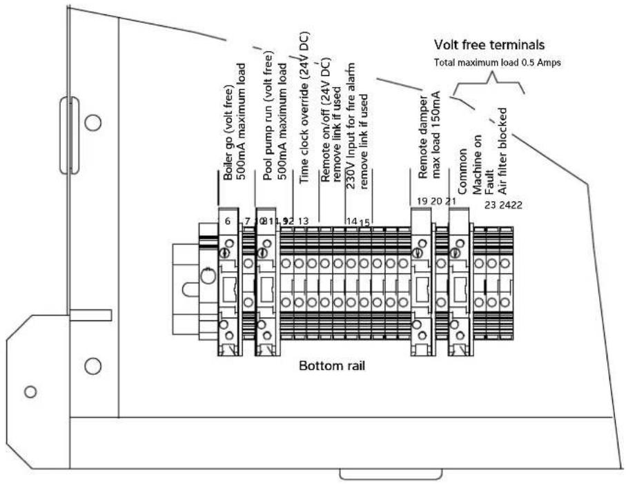
Terminals 6 to 24
"ER" CONFIGURATION

Terminals 6 to 24
"Boiler Go" demand – terminals 6/7
For remote indication of Delta LPHW heat exchangers in operation, used to indicate that the Delta requires LPHW to provide supplementary heating. This could be used to indicate to a boiler, LPHW pump, LPHW control valve, or BMS – whichever are required to enable LPHW flow to the Delta.
These are volt free contacts rated at 0.5A at 230V. Contacts close when LPHW is required.
If the LPHW supply to the Delta is to be activated by the Delta control system, these terminals should be used to enable the LPHW supply. The specifics of this connection depend on the design of the LPHW system.
If the LPHW supply to the Delta is not dependent on demand from the Delta control system, these terminals do not need to be used.
"Pool Pump Run" demand – terminals 8/9
(See page 51.)
"Time clock override" (remote Occupied/Unoccupied) – control terminals 10/11
For remote control of the Delta Occupied/Unoccupied mode.
To enable Occupied mode, the remote switch should be closed. To enable Unoccupied mode, the remote switch should be open. These terminals can be connected to a user switch, pool cover micro-switch, BMS, or whatever system determines the usage mode of the pool. The remote switch should be volt free and suitable to switch 24Vdc.
If remote control of Occupied/Unoccupied is to be used, the User interface should be set to Unoccupied. (See User Settings.)
If this facility is not required, these terminals do not need to be used.
"Remote On/Off" – terminals 12/13
For remote control of On/Standby. To enable Delta to run, the remote switch should be closed. To set the Delta to Standby, the remote switch should be open. The remote switch should be volt free and suitable to switch 24Vdc.
Refer to Standby button function in the User instructions.
If remote On/Off control is required, the factory-fitted link wire should be removed.
If this facility is not required, the factory-fitted link wire should be left in place.
Fire Alarm interface – terminals 14/15
For activating Standby mode in the event of a fire alarm. To enable the Delta to run normally, the remote switch should be closed. To put the Delta into Standby mode, the remote switch should be open. The remote switch should be volt free and suitable to switch 230V. An alarm will show on the control system when the fire alarm is activated.
If the fire alarm interface is required, the factory-fitted link wire should be removed.
If this facility is not required, the factory-fitted link wire should be left in place.
"Remote Damper" control – terminals 19/20
(See page 52.)
"Volt free" status signals – terminals 21/22/23/24
For remote status indication. These are shared volt free contacts rated at a maximum combined 0.5A at 230V.
Terminal 22 – Delta On. Contacts close when Delta is On.
Terminal 23 – Fault. Contacts close when a fault is active.
Terminal 23 – Air filter blocked. Contacts close when filter pressure drop exceeds recommended level. Only available when the optional filter monitoring sensors are fitted in the Delta.
If this facility is not required, these terminals do not need to be used.
"Pool Pump Run" demand – terminals 8/9
For control of the water pump that pumps through the Delta pool water circuit. If this pool water pump runs continuously, these terminals do not need to be used. If this pool water pump is controlled NOT to run continuously, these terminals must be used to start the pump when it would otherwise be off.
These are volt free contacts rated at 0.5A at 230V. Contacts close when the Delta requires pool water flow.
Where the pool water pump is controlled by a time clock (supplied by the others) the Delta control system can override "pump off" periods to ensure pool water flows through the Delta when required. Using these terminals, in conjunction with the pool pump time clock, the pool filtration pump will run when:
a. A "pump on" period has been set by the time clock for filtration purposes.
b. The Delta needs to provide heat recovery to the pool water or the pool requires supplementary heating.
If the pool water pump runs continuously these contacts do not need to be used.
Swimming pool filtration pump time clock
If the pool filtration pump is controlled by its own time clock (not part of Delta), that time clock should be set as required, with the addition of sampling periods to allow the Delta to check and maintain the pool water temperature.
If the pool water temperature is below the set temperature during the sampling period, the Delta unit will continue to run the filtration pump to allow the pool to be heated until the set temperature is reached. (See User Settings).
The Delta control system may override the pool filtration pump time clock.


"Remote Damper" control – terminals 19/20
For control of a remote damper when Advanced Frost Protection is active.
These are powered terminals. Terminal 19 is Live (230V) when Advanced Frost Protection is active. Terminal 19 is fused at 160mA. Terminal 20 is Neutral.
If this facility is not required, these terminals do not need to be used.
Advanced Frost Protection
(Used when the remote damper is installed).
Advanced Frost Protection behaves in the same way as the standard Frost Protection with the addition of closing the remote damper. It also activates under the same conditions as standard, but will not deactivate when the temperature rises immediately. Instead, the machine will check the ambient temperature periodically (every six hours by default).
For each check, the remote dampers are opened for a short time (five minutes), fresh air is allowed to reach the probe and if the temperature has risen above the set point then Advanced Frost Protection is deactivated. If the temperature is still too cold, the machine remains in Advanced Frost Protection mode until the next check. An option to force a check can be found on the Set Points and Switches screen in the User Settings but only while Frost Protection is active.
3.9 AIR QUALITY SENSOR IF OPTION FITTED (KIT D)
Located under the divider panel on the air on side of the machine and preset by the commissioning engineer to the required level.
The fresh air volume is changed to maximum if the air quality drops below the set level at any time.
The position of the shorting plug on the sensor controls the quality of the air and should be set to the - position for adequate air quality with minimum energy consumption.
When the shorting plug is in the mid position a good air quality level is achieved giving optimum energy consumption.
When the shorting plug is in the + position a very good air quality level is achieved at the expense of increased energy consumption.
In the interests of safety, the position of the shorting plug should only be changed by an electrician due to the danger of electric shock.
The air quality sensor adapts itself to the local air quality. The sensor takes about one minute to reach its operating temperature, but takes about two days to stabilize. For this reason the power supply to the Delta should not be interrupted.
3.10 NETWORK CONNECTION
For screen mirroring to function (see Section 2.2 Remote access) the Delta touchscreen must be connected to a LAN (local area network). The RJ45 Ethernet port on the front panel may be used. Alternatively the connection may be made directly to the RJ45 Ethernet port on the back of the touchscreen, after disconnecting the front panel extension cable. The Ethernet controller supports the MDI/MDIX auto-crossover cable function, and may be used with either T568A or T568B wiring standards.
The default network IP address for the Delta is 192.168.1.150, but may be changed as required (see section 2.1 Network setting).
If the Delta is only to be accessed by devices connected to the same network, no further network setup is necessary. If the Delta is to be accessed from devices NOT connected to the same network, it is necessary to set port forwarding to the network IP address of the Delta.
Ports to be forwarded
80
6000
6002
If the Delta is to be accessed from devices NOT connected to the same network, a static public IP address for the network is recommended. If your ISP (internet service provider) is not able to provide a static IP address, third party solutions are available to provide a static IP address, which may involve a cost.
Once set up, the Delta may be accessed from an ActiveX enabled browser such as Internet Explorer, or a mobile device using the Vijeo Design'Air app. See section 2.2 Remote access for more details.
3.11 BMS CONNECTION
(BUILDING MANAGEMENT SYSTEM)

In addition to screen mirroring to the touchscreen (see Section 2.2), the following options for connecting a BMS are included as standard.
- Modbus/RTU
- BACnet/IP
• BACnet MS/TP
Modbus is available via the RS485-2 interface on the PLC.
BACnet IP is available via the Ethernet port on the PLC.
BACnet MS/TP is available via the RS485-2 interface on the PLC.
(Only one BACnet connection may be used at any one time. BACnet and Modbus may not be used at the same time.)
The Ethernet controller supports the MDI/MDIX auto-crossover cable function, and may be used with either T568A or T568B wiring standards.
For configuration settings, see the BMS Settings screen and PLC Ethernet Setting screen in Section 2.2 Advanced Settings.
For Modbus Variable list and BACnet Object list please consult the Dantherm Group.
3.12 OPTIONAL REMOTE SENSOR BOX
A remote sensor box is available allowing the air temperature and humidity sensors to be mounted in the pool hall. This may be beneficial if the sensors located within the Delta cabinet are not able to get a representative measurement of the conditions.
When using 0.5mm^2 cable, the maximum total distance between the sensors and their terminals is 20 metres.

Remote sensor box
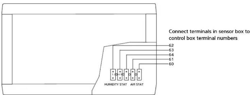
Replace covers
After the Remote Sensor Box has been connected it may be necessary to calibrate the sensor offsets. See Advanced Settings, OFFSETS for how to do this.
4.0 AFTER INSTALLATION
When the Delta leaves the Dantherm Ltd. factory it is fully tested and is ready to operate when connected to the correct power supply, services and ductwork. The default settings allow the Delta to be powered and started safely, provided the pre-commissioning checklist has been actioned.
Pre-commissioning checklist
In order for the Delta to be properly commissioned after installation, the following actions are essential:
- The pool hall structure is complete and sealed according to the design specification.
- All ductwork is fully installed and finished, including all inlet and outlet grilles.
- The pool water filtration system is connected, complete, fully commissioned and operational.
- LPHW connections are complete and the heat source is installed, fully commissioned and operational.
- All electrical connections are complete and all power and control systems are wired and fully commissioned.
Initial start-up
After installation and completion of the services on the pre-commissioning checklist, the Delta can be started:
- Connect power by turning on the local isolator.
- Confirm the red power light illuminates.
- The touchscreen should turn on and go through a start-up sequence after a short delay. If the touchscreen does not start, check:
- Correct phase rotation
– Control MCB inside the electric box is turned on - Touchscreen cable connections
- When the touchscreen displays the first home screen, the Delta can be turned on via the touchscreen (see User Settings).
The Delta should be started well before commissioning to ensure the pool water and air have reached design temperatures prior to commissioning. The default settings will normally allow the Delta to stabilise the conditions ready for commissioning.
Several days may be required to heat up the pool water. If the pool is covered, the Delta may be put into 'water heating only' mode (see User Settings) to save energy on air heating while the pool heats up. If high humidity or condensation occurs, the Delta should be returned to full-function operation.
When connected to an air-source heat pump as the LPHW source, it may be necessary to swap the Delta over to 'heat recovery to air priority' to help heat the pool hall (see User Settings).
Commissioning
For full commissioning procedure, please refer to separate commissioning document and report, which should be completed fully. Summary of commissioning procedure:
Pool hall and plant room
√ Check – is the building finished in accordance with the original plans and specification, ready for commissioning? Check current temperatures and humidity, calibrate air/water temperature and humidity sensors.
√ Check – is Delta service and maintenance access adequate?
Ductwork and air flow
√ Check – is all ductwork and any plenum chamber insulated? Special attention should be made to the insulation of the Exhaust Air and Fresh Air inlet ducting to prevent condensation problems.
√ Check – are there any significant draughts in the pool hall (or plant room if used as a plenum) through poorly fitting doors, windows, pipe ducts, etc? This will let in unwanted ambient air, affecting control, efficiency and energy usage.
√ Check – are exhaust air and fresh air ductwork properly sealed from plant room and other parts of the building?
√ Check – the above should be checked by measuring plant room and pool hall air temperatures. If the plant room is acting as a plenum chamber both temperatures should correspond. If the plant room air temperature is lower, then ambient air is leaking in. This leak should be located and rectified.
√ Check – are all air inlets and outlets free from obstructions? Are exhaust air and fresh air grilles adequately separated and not allowing recirculation from exhaust to inlet?
√ Check – are air filters clean?
√ Action – measure air volumes and commission fan speeds.
Pool water
√ Check – is pool water connected correctly?
√ Check – is pool water flow rate correct?
√ Check – is pool cover installed and used?
LPHW
√ Check – is LPHW connected correctly and insulated?
√ Check – is LPHW flow rate correct?
√ Check – size and type of LPHW heat source?
√ Record – LPHW flow and return temperatures with air and water heat exchangers in operation.
Electrical
√ Check – is electric installation complete?
√ Check – is local isolator present?
√ Check – is MCB suitable for the Delta model installed?
√ Record – MCB details
√ Check – is fan rotation direction correct?
√ Record – which customer terminals are in use.
√ Record – compressor and fan running amps.
Heat pump
√ Check: Are all heat exchangers in good condition?
√ Record: Confirm refrigeration operating pressures.
Controls
√ Check – function of touchscreen.
√ Check and record – Recalibrate sensors, if necessary. (Ensure Delta has been running for at least 30 minutes before calibration).
√ Check and record – User Settings and record.
√ Check – Time clock or remote override settings.
√ Check – is auto-restart on power loss set to On or Off?
Commissioning report
√ Action – complete commissioning report with all details.
√ Check – Delta is fully operational following commissioning.
√ Check – operator has access to User instructions.
Operator handover
When commissioning is complete and there are no outstanding actions to complete, the Delta is ready to be handed over to the operator. The operator should be made aware of the user instructions and familiarised with the basic controls on the Home screens.
The operator should be made aware of the ongoing maintenance requirements. (See 4.1.)
4.1 MAINTENANCE
Operations carried out during a planned maintenance visit are as follows:
- Replace all belts & filters where fitted.
- Check operation and condition of all fans and compressors.
- Check capacitor tolerances.
- Check condition of all heat exchangers/evaporators.
- Check refrigeration system parameters.
- Check operation of control valves.
- Check for water leaks.
- Check drip trays and internal drain lines for blockages and clear.
- Check operation of controls and calibrate as necessary.
- Check operation of interlocks in use.
- Final check on overall operation of unit.
- Indicate on report any faults found or causes for concern.
Frequencies recommended are as follows:
Model Light/Medium use Heavy use
Delta 1 to 12 2 visits per year 4 visits per year
Delta 14 and 16 3 visits per year 4 visits per year
Filters may need more frequent inspection.
In order to comply with European Union F-Gas regulations, it is necessary to leak test hermetically sealed systems with more than 6kg refrigerant annually. The operator of the unit is responsible for seeing that this test is carried out. Delta machines from Delta 6 upwards need to have this annual test.
4.2 CIRCUIT DIAGRAMS


POWER CIRCUIT 1 PHASE DELTA 1A AND 2A

flowchart
graph TD
    A["CONTROL CIRCUIT BREAKER"] --> B["COMPRESSOR CIRCUIT BREAKER"]
    B --> C["MAIN FAN CIRCUIT BREAKER"]
    C --> D["EXHAUST FAN CIRCUIT BREAKER"]
    D --> E["MAIN FAN"]
    E --> F["EXHAUST FAN"]
    G["CONTRACTORS"] --> H["COMPRESSOR"]
    H --> I["MAIN CANDUM BREAKER"]
    I --> J["EXHAUST FAN"]
    K["DELTA 1A"] --> L["10A"]
    K --> M["6A"]
    K --> N["20A"]
    O["N"] --> P["Control Circuit Breaker"]
    Q["L1"] --> R["Control Circuit Breaker"]
    S["See ABOVE"] --> T["Main Fan"]
    U["See ABOVE"] --> V["Exhaust Fan"]
POWER CIRCUIT 1 PHASE DELTA 4A & 6A

flowchart
graph TD
    A["Main Fan"] --> B["Exhaust Fan"]
    B --> C["Compressor"]
    C --> D["Control"]
    E["CONTROLS"] --> F["Exhaust Fan"]
    F --> G["Compressor"]
    G --> H["Control"]
    I["CONTRACTORS"] --> J["Exhaust Fan"]
    J --> K["Main Fan"]
    L["COMPRESSION"] --> M["Main Fan"]
    N["EXhaust Fan"] --> O["Main Fan"]
    P["COMPRESSION"] --> Q["Main Fan"]
    R["EXhaust Fan"] --> S["Main Fan"]
    T["COMPRESSION"] --> U["Main Fan"]
    V["EXhaust Fan"] --> W["Main Fan"]
    X["COMPRESSION"] --> Y["Main Fan"]
    Z["EXhaust Fan"] --> AA["Main Fan"]
    AB["COMPRESSION"] --> AC["Main Fan"]
    AD["EXhaust Fan"] --> AE["Main Fan"]
    AF["COMPRESSION"] --> AG["Main Fan"]
    AH["EXhaust Fan"] --> AI["Main Fan"]
    AJ["COMPRESSION"] --> AK["Main Fan"]
    AL["EXhaust Fan"] --> AM["Main Fan"]
    AN["COMPRESSION"] --> AO["Main Fan"]
    AP["EXhaust Fan"] --> AQ["Main Fan"]
    AR["COMPRESSION"] --> AS["Main Fan"]
    AT["EXhaust Fan"] --> AU["Main Fan"]
    AV["COMPRESSION"] --> AW["Main Fan"]
    AX["EXhaust Fan"] --> AY["Main Fan"]
    AZ["COMPRESSION"] --> BA["Main Fan"]
    BB["EXhaust Fan"] --> BC["Main Fan"]
    BD["COMPRESSION"] --> BE["Main Fan"]
    BF["EXhaust Fan"] --> BG["Main Fan"]
    BH["COMPRESSION"] --> BI["Main Fan"]
    BJ["EXhaust Fan"] --> BK["Main Fan"]
    BL["COMPRESSION"] --> BM["Main Fan"]
    BN["EXhaust Fan"] --> BO["Main Fan"]
    BP["COMPRESSION"] --> BQ["Main Fan"]
    BR["EXhaust Fan"] --> BS["Main Fan"]
    BT["COMPRESSION"] --> BU["Main Fan"]
    BV["EXhaust Fan"] --> BW["Main Fan"]
    BX["COMPRESSION"] --> BY["Main Fan"]
    BZ["EXhaust Fan"] --> CA["Main Fan"]
    CB["COMPRESSION"] --> CC["Main Fan"]
    CD["EXhaust Fan"] --> CE["Main Fan"]
    CF["COMPRESSION"] --> CG["Main Fan"]
    CH["EXhaust Fan"] --> CI["Main Fan"]
    CJ["COMPRESSION"] --> CK["Main Fan"]
| Model | MCB Circuit Breakers | |||
| MAIN FAN | EXHAUST FAN | COMPRESSOR | CONTROL | |
| DELTA 1A | 10A | 6A | 20A | 2A |
| DELTA 2A | 10A | 6A | 25A | 2A |
| Mode | MCB Circuit Breakers | |||
| MAN FAN | EXHAUST FAN | COMPRESSOR | CONTROL | |
| DELTA 4A | 16A | 6A | 25A | 2A |
| DELTA 6A | 16A | 6A | 32A | 2A |
POWER CIRCUIT 3 PHASE DELTA 1B & 2B

flowchart
graph TD
    A["CONTRACTORS"] --> B["COMPRESSOR"]
    B --> C["CONTROLLER MOTOR STARTER"]
    C --> D["CONTROL CIRCUIT BREAKER"]
    D --> E["MAIN FAN CIRCUIT BREAKER"]
    E --> F["EXHAUST FAN CIRCUIT BREAKER"]
    F --> G["HEALTH CIRCUIT BREAKER"]
    G --> H["HEALTH CIRCUIT BREAKER"]
    H --> I["HEALTH CIRCUIT BREAKER"]
    I --> J["HEALTH CIRCUIT BREAKER"]
    J --> K["HEALTH CIRCUIT BREAKER"]
    K --> L["HEALTH CIRCUIT BREAKER"]
    L --> M["HEALTH CIRCUIT BREAKER"]
    M --> N["HEALTH CIRCUIT BREAKER"]
    N --> O["HEALTH CIRCUIT BREAKER"]
    O --> P["HEALTH CIRCUIT BREAKER"]
    P --> Q["HEALTH CIRCUIT BREAKER"]
    Q --> R["HEALTH CIRCUIT BREAKER"]
    R --> S["HEALTH CIRCUIT BREAKER"]
    S --> T["HEALTH CIRCUIT BREAKER"]
    T --> U["HEALTH CIRCUIT BREAKER"]
    U --> V["HEALTH CIRCUIT BREAKER"]
    V --> W["HEALTH CIRCUIT BREAKER"]
    W --> X["HEALTH CIRCUIT BREAKER"]
    X --> Y["HEALTH CIRCUIT BREAKER"]
    Y --> Z["HEALTH CIRCUIT BREAKER"]
    Z --> AA["HEALTH CIRCUIT BREAKER"]
    AA --> AB["HEALTH CIRCUIT BREAKER"]
    AB --> AC["HEALTH CIRCUIT BREAKER"]
    AC --> AD["HEALTH CIRCUIT BREAKER"]
    AD --> AE["HEALTH CIRCUIT BREAKER"]
    AE --> AF["HEALTH CIRCUIT BREAKER"]
    AF --> AG["HEALTH CIRCUIT BREAKER"]
    AG --> AH["HEALTH CIRCUIT BREAKER"]
    AH --> AI["HEALTH CIRCUIT BREAKER"]
    AI --> AJ["HEALTH CIRCUIT BREAKER"]
    AJ --> AK["HEALTH CIRCUIT BREAKER"]
    AK --> AL["HEALTH CIRCUIT BREAKER"]
    AL --> AM["HEALTH CIRCUIT BREAKER"]
    AM --> AN["HEALTH CIRCUIT BREAKER"]
    AN --> AO["HEALTH CIRCUIT BREAKER"]
    AO --> AP["HEALTH CIRCUIT BREAKER"]
    AP --> AQ["HEALTH CIRCUIT BREAKER"]
    AQ --> AR["HEALTH CIRCUIT BREAKER"]
    AR --> AS["HEALTH CIRCUIT BREAKER"]
    AS --> AT["HEALTH CIRCUIT BREAKER"]
    AT --> AU["HEALTH CIRCUIT BREAKER"]
    AU --> AV["HEALTH CIRCUIT BREAKER"]
    AV --> AW["HEALTH CIRCUIT BREAKER"]
    AW --> AX["HEALTH CIRCUIT BREAKER"]
    AX --> AY["HEALTH CIRCUIT BREAKER"]
POWER CIRCUIT 3 PHASE DELTA 4B,6B,8B,10B,12B,14B & 16B

flowchart
graph TD
    A["CONTRACTORS"] --> B["COMpressor"]
    A --> C["MAIN FAN"]
    A --> D["EXHAUST FAN 3 PHASE DELTA 100.120, 149 & 168"]
    A --> E["EXHAUST FAN 1 PHASE DELTA 60.60"]
    B --> F["CONTROL CIRCUIT SWITCH"]
    C --> G["MAIN FAN METER SWITCH"]
    D --> H["EXHAUST FAN METER SWITCH"]
    E --> I["EXHAUST FAN METER SWITCH"]
    F --> J["OUT PHASE ROTATION RELAY"]
    G --> K["OUT PHASE ROTATION RELAY"]
    H --> L["OUT PHASE ROTATION RELAY"]
    I --> M["OUT PHASE ROTATION RELAY"]
FOR DELTA 4B, 6B, 8B, EXHAUST FAN SETTING DENOTES RATING FOR SINGLE POLE MCTS CIRCUIT BREAKER
| Model MCB Circuit Breakers MOTOR STARTER | OVERLOAD SETTING | |||
| MAIN FAN | EXHAUST FAN | CONTROL COMPRESSOR MAIN | ||
| DELTA 1B | 10A | 6A | 2A | 4.8A |
| DELTA 2D | 10A | 6A | 2A | 5.8A |
| MODEL: MCR | Circuit Breakers MOTOR STARTER | OVER LOAD SETTING MODE MOTOR ST | ||
| FAN | EXHAUST FAN COMMISSION CONTROL CIRCUIT BREAKER | |||
| DELTA 4B | 4A | 6A (SEE NOTE) | 5.8A | 1.6A |
| ARTER OVERLOAD SET | NG | |||
| MAN FAN | EXHAUST FAN COMPRISSOR CONTROL | CIRCUIT BREAKER | ||
| DELTA 6S | 4A | 6A (SEE NOTE) | 8.8A | 1.8A |
| DELTA 6S | 4A | 10A (SEE NOTE) | 9.5A | 1.8A |
| DELTA 10B | 5.8A 4.0A | 12.0A | 1.8A | |
| DELTA 17B | 5.8A 4.0A | 13.1A | 1.8A | |
| DELTA 14B | 5.0A 6.2A | 23.6A | 1.8A | |
| DELTA 16B | 5.0A 6.2A | 32.0A | 1.8A | |
Relay Functions, DELTA 1 to DELTA 16
R1 Energised by healthy HP and LP switches (and Soft Start if fitted)
A) Indicates the state of the LP and HP switches to the PLC (Closes on fault)
B) Allows the compressor to start (when required) if HP/LP switches are healthy.
R2 Energised by No. 6 on controller for LPHW air heating.
A) Opens LPHW valve for air heating.
R3 Energised by fire alarm being healthy (if required and item is fitted to machine).
A) Indicates the state of the fire alarm to the PLC (Closes in alarm).
B) Cuts the outputs to the PLC in the event of a fire alarm.
R4 Energised by poor air quality (if required and item is fitted to machine).
A) Indicates to the PLC that the air quality is poor (Closes when the air is poor).
5.0 DATA SHEET
| Specifications Units | DT1ADT1B | DT2ADT2B | DT4ADT4B | DT6ADT6B | DT8BDT | 10BDT12B | DT14BDT16B | |||
| DEHUMIDIFICATION DUTY | ||||||||||
| Heat pump dehumidification 28°C/60%, min. fresh air L/h 4.5 5-5 6 | h 4.5 5-5 6 | 0 8.0 10.0 | 12.0 14.0 28.0 | 30.0 | ||||||
| Total at 18°C dew point (summer) max. fresh air L/h 6.5 | 7.3 9.0 12 | 0 15.0 18.0 | 21.0 41.0 48.0 | |||||||
| Total at 7°C dew point (winter) mid. fresh air L/h 9.5 10.7 | 12.1 16.1 | 20.1 24.2 | 28.2 55.0 60.5 | |||||||
| VDI 2089 L/h 7.6 8.2 9.5 12.6 | 15.8 19.0 22.2 42.5 51.4 | |||||||||
| Total DH + VDI 2089 at 12.5°C dew point - summer L/h 9.8 | 10.9 12.5 | 16.6 20.8 | 25.0 29.2 56.5 | 62.4 | ||||||
| HEAT TO AIR | ||||||||||
| Heat pump heat recovery - Mode A (priority to water) | kW 1.3 1.5 | 1.4 1.5 1.6 2.0 | 2.5 6.0 7.0 | |||||||
| Heat pump heat recovery - Mode B (priority to air) kW | 3.8 4.9 5.1 | 5.6 8.0 10.0 | 12.1 30.0 35.0 | |||||||
| Standard LPHW at 80°C flow - see section 5.1 | kW | 20 | 22 | 25 | 30 | 35 | 38 | 42 | 85 | 90 |
| Upgraded LPHW at 55°C flow - see section 5.2 | kW | 17 | 19 | 21 | 26 | 30 | 32 | 36 | 72 | 77 |
| Total - std. LPHW + Mode A/Mode B heat recovery | kW | 21.3/23.8 | 23.5/26.9 | 26.4/30.1 | 31.5/36.6 | 36.6/43.0 | 40.0/48.0 | 44.5/54.1 | 91.0/115.0 | 97.0/125.0 |
| Available for fabric losses, std. LPHW, Mode A, -5°C | kW | 14.3 | 15.9 | 17.6 | 19.8 | 21.9 | 22.4 | 24.0 | 51.7 | 50.1 |
| Available for fabric losses, upo LPHW, Mode A, -5°C kW | 11.3 12.6 | 13.9 15.3 16 | 16.7 17.7 | 29.0 36.6 | ||||||
| HEAT TO POOL WATER | ||||||||||
| Heat pump heat recovery - Mode A (priority to water) | kW 4.0 5.5 | 5.8 8.0 10.0 | 2.5 15.0 35.0 | 43.0 | ||||||
| Heat pump heat recovery - Mode B (priority to air) kW | 1.7 2.2 2.3 | 8.0 3.7 4.6 5.5 | 12.0 14.0 | |||||||
| LPHW at 80°C flow - see section 5.1 | kW | 23 | 23 | 33 | 33 | 33 | 40 | 40 | 65 | 65 |
| LPHW at 55°C flow - see section 5.2 | kW | 11 | 11 | 16 | 16 | 16 | 20 | 20 | 32 | 32 |
| Total - LPHW + Mode A/Mode B heat recovery | kW | 27.0/24.7 | 28.5/25.2 | 38.8/35.3 | 41.0/36.0 | 43.0/36.7 | 52.5/44.6 | 55.0/45.5 | 100.0/77.0 | 108.0/79.0 |
| Flow rate - pool water ± 10% | L/minute | 31.5 | 31.5 | 38.0 | 40.0 | 40.0 | 54.0 | 54.0 | 100.0 | 100.0 |
| Pressure drop at rated flow | m/kPa | 1.4/13.7 | 1.4/13.7 | 2.5/24.5 | 2.5/24.5 | 2.5/24.5 | 3.5/34.3 | 3.5/34.3 | 3.5/34.3 | 3.5/34.3 |
| Maximum working pressure | bar 3.5 | 3.5 3.5 3.5 | 3.5 3.5 3.5 | 3.5 | ||||||
| Plate heat exchanger pool water flow meter setting | L/minute | 17.5 | 17.5 | 24.0 | 24.0 | 24.0 | 29.0 | 29.0 | - | - |
| COOLING DUTY | ||||||||||
| Cooling duty - sensible | kW | 2.0/- | 2.5/- | 2.9 | 3.9 | 4.7 | 5.9 | 7.1 | 13.0 | 15.0 |
| Cooling duty - total | kW | 3.0/- | 4.0/- | 4.2 | 5.5 | 6.7 | 8.4 | 10.1 | 23.0 | 28.0 |
| LPHW DATA | ||||||||||
| Rec. min. boiler capacity (standard LPHW at 80°C) | kW | 43 | 45 | 58 | 63 | 68 | 78 | 82 | 150 | 155 |
| Rec. min. boiler capacity (upgraded LPHW at 55°C) | kW | 28 | 30 | 37 | 42 | 46 | 52 | 56 | 104 | 109 |
| Flow rate - standard LPHW | L/minute | 28 | 28 | 35 | 39 | 42 | 49 | 53 | 115 | 115 |
| Flow rate - upgraded LPHW | L/minute | 40 | 40 | 50 | 58 | 63 | 69 | 73 | 202 | 202 |
| Pressure drop at rated flow rate | m/kPa | 2.0/19.6 | 2.0/19.6 | 2.5/24.5 | 2.5/24.5 | 2.5/24.5 | 2.8/27.4 | 2.8/27.4 | 4.0/39.2 | 4.0/39.2 |
| Maximum working pressure | bar | 6 | 6 | 6 | 6 | 6 | 6 | 6 | 6 | 6 |
| Plate heat exchanger LPHW flow meter setting | L/minute | 14 | 14 | 19 | 19 | 19 | 23 | 23 | - | - |
| ELECTRICAL | ||||||||||
| Total power consumed - nominal | kW 2.6 | 2.9 2.9 3.4 4 | 5.9 7.4 12 | 17.0 | ||||||
| Minimum supply capacity (FLA) 230V/1N/50Hz | A | 22 | 24 | 25 | 33 | - | - | - | - | - |
| Minimum supply capacity (FLA) 400V/3N/50Hz | A | 10 | 11 | 13 | 16 | 19 | 22 | 23 | 38 | 47 |
| Maximum supply fuse 230V/1N/50Hz | A | 32 | 32 | 40 | 50 | - | - | - | - | - |
| Maximum supply fuse 400V/3N/50Hz | A | 16 | 20 | 20 | 25 | 25 | 32 | 32 | 50 | 63 |
| MAIN FAN DATA - VARIABLE SPEED | ||||||||||
| Design air flow - supply volume | m^3/h | 2500 | 2600 | 3000 | 4000 | 5000 | 6000 | 7000 | 10000 | 12000 |
| Design external static pressure | Pa | 150 | 150 | 200 | 200 | 200 | 250 | 250 | 250 | 250 |
| Maximum external static pressure standard LPHW | Pa | 200 | 200 | 700 | 450 | 800 | 800 | 500 | 800 | 450 |
| Maximum external static pressure upgraded LPHW | Pa | 180 | 180 | 670 | 410 | 740 | 760 | 450 | 750 | 400 |
| Design running amps - 230V/1N fans | A | 3.5 | 3.5 | 2.4 | 3.1 | - | - | - | - | - |
| Design running amps - 400V/3N fans | A | - | - | 0.9 | 1.1 | 1.9 | 2.6 | 4.0 | 3.7 | 6.4 |
| FLA - 230V/1N fans | A | 5.2 | 5.2 | 6.8 | 6.8 | - | - | - | - | - |
| FLA - 400V/3N fans | A | - | - | 4.0 | 4.0 | 4.0 | 5.8 | 5.8 | 8.0 | 8.0 |
| EXHAUST FAN DATA - VARIABLE SPEED | ||||||||||
| Design air flow - summer maximum fresh air volume | m^3/h | 1200 | 1300 | 1500 | 2000 | 2500 | 3000 | 3500 | 6700 | 8000 |
| Air flow - winter maximum fresh air volume | m^3/h | 600 | 650 | 750 | 1000 | 1250 | 1500 | 1750 | 3350 | 4000 |
| Air flow - minimum fresh air volume | m^3/h | 120 | 130 | 150 | 200 | 250 | 300 | 350 | 670 | 850 |
| Design external static pressure | Pa | 50 | 50 | 80 | 100 | 100 | 150 | 150 | 150 | 150 |
| Max external static pressure | Pa | 300 | 290 | 280 | 200 | 110 | 500 | 500 | 500 | 320 |
| Design running amps - 230V/1N fans | A | 0.9 | 0.9 | 1.7 | 2.3 | 3.0 | - | - | - | - |
| Design running amps - 400V/3N fans | A | - | - | - | - | - | 1.0 | 1.4 | 2.7 | 3.7 |
| FLA - 230V/1N fans | A | 3.0 | 3.0 | 3.0 | 3.0 | 5.2 | - | - | - | - |
| FLA - 400V/3N fans | A | - | - | - | - | - | 4.0 | 4.0 | 6.2 | 6.2 |
| PART F - ACTUAL SFP AT DESIGN CONDITION | ||||||||||
| W/L/s | 1.27 | 1.23 | 0.94 | 0.89 | 1.23 | 1.35 | 1.64 | 1.47 | 2.07 | |
| COMPRESSOR DATA | ||||||||||
| Nominal power consumed | kW 1.7 | 2.0 2.1 2.4 27 | 3.6 4.2 8.2 | 10.1 | ||||||
| Nominal RLA - 230V/1N/50Hz | A | 10.2 | 12.4 | 12.4 | 12.8 | - | - | - | - | - |
| Starting current - 230V/1N/50Hz | A | 62 | 62 | 62 | 103 | - | - | - | - | - |
| Starting current - 230V/1N/50Hz (with soft start) | A | 28 | 28 | 28 | 34 | - | - | - | - | - |
| Nominal RLA - 400V/3N/50Hz | A | 3.2 4.8 4.8 4.7 5.1 6.4 8.9 14.1 22.4 | ||||||||
| Starting current - 400V/3N/50Hz | A | 38 | 30.5 | 30.5 | 48 | 48 | 48 | 101 | 102 | 174 |
| Starting current - 400V/3N/50Hz (with soft start) | A | 15 | 16 | 16 | 25 | 25 | 25 | 34 | 34 | 41 |
| GENERAL DATA | ||||||||||
| HERMETIC REFRIGERATION SYSTEM | ||||||||||
| Refrigerant charge - R407C | kg | 3.0 | 3.0 | 6.0 | 7.8 | 7.8 | 9.0 | 8.0 | 21.5 | 22.5 |
| Weight - unpacked | kg | 300 | 310 | 350 | 360 | 370 | 410 | 460 | 954 | 1020 |
For accurate project sizing consult the Dantherm Group or your local representative
Mode A: heat recovery biased to pool water when pool water temperature not satisfied
Mode B: heat recovery biased to pool hall air when pool water temperature satisfied
R407c global warming potential (GWP): 1774
SD675650 ISSUE 6 M172 DELTA
1mm water gauge = 9.8Pa
1m head = 9.8kPa
1L/minute = 0.22gallon/minute (Imperial)
5.1 LPHW HEATING DATA - DELTA WITH STANDARD AIR HEATER
| flow °C 80 70 | 60 50 45 | ||||||
| DELTA 1 Standard | air heating capacity kW 20.0 16.0 12.0 8.0 6.0Available for fabric losses, mode A, -5°C kW 14.3Pool water heating capacity kW 23.0 18.4 13.8 9 | 10.3 6.3 2.3 0.32 6.9 | |||||
| Recommended boiler capacity kW 43.0 34.4 25.8LPHW flow rate | 17.2L/min | 12.928 28 28 28 28 | |||||
| Return temperature air heating onlyReturn temperature pool heating onlyReturn temperature both heating | °C°C°C | 69.868.258.0 | 61.860.652.4 | 53.952.946.8 | 45.945.341.2 | 41.941.538.4 | |
| flow °C 80 70 | 60 50 45 | ||||||
| DELTA 2 Standard | air heating capacity kW 22.0 17.6 13.2 8.8 6.6Available for fabric losses, mode A, -5°C kW 15.9Pool water heating capacity kW 23.0 18.4 13.8 9 | 11.5 7.1 2.7 0.52 6.9 | |||||
| Recommended boiler capacity kW 45.0 36.0 27.0LPHW flow rate | 18.0L/min | 13.528.0 28 28 28 | 28 | ||||
| Return temperature air heating onlyReturn temperature pool heating onlyReturn temperature both heating | °C°C°C | 68.768.257.0 | 61.060.651.6 | 53.252.946.2 | 45.545.340.8 | 41.641.538.1 | |
| flow °C 80 70 | 60 50 45 | ||||||
| DELTA 4 | Standard air heating capacityAvailable for fabric losses, mode A, -5°C kW 17.6Pool water heating capacity kW 33.0 26.4 19.8 13.8 13.2 | kW12.6 7.6 2.6 0.13.2 | 25.09 | 20.0 | 15.0 | 10.0 | 7.5 |
| Recommended boiler capacity kW 58.0 46.4 34.8LPHW flow rate | 23.2L/min | 17.435.0 35 35 35 | 35 | ||||
| Return temperature air heating onlyReturn temperature pool heating onlyReturn temperature both heating | °C°C°C | 69.866.556.2 | 61.859.251.0 | 53.951.945.7 | 45.944.640.5 | 41.940.937.9 | |
| flow °C 80 70 | 60 50 45 | ||||||
| DELTA 6 | Standard air heating capacityAvailable for fabric losses, mode A, -5°C kW 19.8Pool water heating capacity kW 33.0 26.4 19.8 13.8 13.2 | kW13.8 7.8 1.8 -1.23.2 | 30.09 | 24.0 | 18.0 | 12.0 | 9.0 |
| Recommended boiler capacity kW 63.0 50.4 37.8LPHW flow rate | 25.2L/min | 18.939 39 39 39 39 | |||||
| Return temperature air heating onlyReturn temperature pool heating onlyReturn temperature both heating | °C°C°C | 69.067.956.8 | 61.260.351.5 | 53.452.746.1 | 45.645.140.7 | 41.741.438.1 | |
| flow °C 80 70 | 60 50 45 | ||||||
| DELTA 8 | Standard air heating capacityAvailable for fabric losses, mode A, -5°C kW 21.9Pool water heating capacity kW 33.0 26.4 19.8 13.8 13.2 | kW14.9 7.9 0.9 -2.63.2 | 35.09 | 28.0 | 21.0 | 14.0 | 10.5 |
| Recommended boiler capacity kW 68.0 54.4 40.8LPHW flow rate | 27.2L/min | 20.442 42 42 42 42 | |||||
| Return temperature air heating onlyReturn temperature pool heating onlyReturn temperature both heating | °C°C°C | 68.168.756.8 | 60.461.051.4 | 52.853.246.1 | 45.245.540.7 | 41.441.638.0 | |
| flow °C 80 70 | 60 50 45 | ||||||
| DELTA 10 | Standard air heating capacityAvailable for fabric losses, mode A, -5°C kW 22.4Pool water heating capacity kW 40.0 32.0 24.0 16.0 | kW14.8 7.2 -0.46.0 | 38.0-4.212.0 | 30.4 | 22.8 | 15.2 | 11.4 |
| Recommended boiler capacity kW 78.0 62.4 46.8LPHW flow rate | 31.2L/min | 23.449 49 49 49 49 | |||||
| Return temperature air heating onlyReturn temperature pool heating onlyReturn temperature both heating | °C°C°C | 68.968.357.2 | 61.160.651.7 | 53.353.046.3 | 45.645.340.9 | 41.741.538.2 | |
| flow °C 80 70 | 60 50 45 | ||||||
| DELTA 12 | Standard air heating capacityAvailable for fabric losses, mode A, -5°C kW 24.0Pool water heating capacity | kW15.6 7.2 -1.2kW 40.0 32.0 | 42.0-5.424.0 16.0 | 33.612.0 | 25.2 | 16.8 | 12.6 |
| Recommended boiler capacity kW 82.0 65.6 49.2LPHW flow rate | 32.8L/min | 24.653 53 53 53 53 | |||||
| Return temperature air heating onlyReturn temperature pool heating onlyReturn temperature both heating | °C°C°C | 68.669.257.8 | 60.961.352.3 | 53.253.546.7 | 45.545.741.1 | 41.641.838.3 | |
| flow °C 80 70 | 60 50 45 | ||||||
| DELTA 14 | Standard air heating capacityAvailable for fabric losses, mode A, -5°C kW 51.7Pool water heating capacity kW 65.0 52.0 39.0 26.0 | kW34.7 17.7 0.7 -7.86.0 | 85.019.5 | 68.0 | 51.0 | 34.0 | 25.5 |
| Recommended boiler capacityLPHW flow rate | kWL/min | 150.0115 | 120.0115 | 90.0115 | 60.0115 | 45.0115 | |
| Return temperature air heating onlyReturn temperature pool heating onlyReturn temperature both heating | °C°C°C | 69.471.961.3 | 61.563.555.0 | 53.655.148.8 | 45.846.842.5 | 41.842.639.4 | |
| flow °C 80 70 | 60 50 45 | ||||||
| DELTA 16 | Standard air heating capacityAvailable for fabric losses, mode A, -5°CPool water heating capacity kW 65.0 52.0 39.0 26.0 | kWkWL/min | 90.050.119.5 | 72.032.1 | 54.014.1 | 36.0-3.9 | 27.0-12.9 |
| Recommended boiler capacityLPHW flow rate | kWL/min | 155.0115 | 124.0115 | 93.0115 | 62.0115 | 46.5115 | |
| Return temperature air heating onlyReturn temperature pool heating onlyReturn temperature both heating | °C°C°C | 68.871.960.7 | 61.063.554.5 | 53.355.148.4 | 45.546.842.3 | 41.642.639.2 |
5.2 LPHW HEATING DATA - DELTA WITH UPGRADED AIR HEATER
(WHERE MODEL NUMBER INCLUDES +E)
| flow °C 65 60 | 55 50 45 | ||||||
| DELTA 1 Upgraded | air heating capacity kW 23.3 20.0 16.7 13.3 10.0 Available for fabric losses, mode A, -5°C kW 17.6 Pool water heating capacity kW 16.1 13.8 11.5 9 | 14.3 10.9 7.6 4.3 2.6.9 | |||||
| Recommended boiler capacity kW 39.4 33.8 28.2 LPHW flow rate L/min 40 40 40 40 | 22.5 16.9 | ||||||
| Return temperature air heating only °C Return temperature pool heating only Return temperature both heating | 56.6 52.8 49 °C °C | 0 45.2 41.4 59.2 50.9 | 55.1 47.9 | 50.9 44.9 | 46.7 41.9 | 42.5 38.9 | |
| flow °C 65 60 | 55 50 45 | ||||||
| DELTA 2 Upgraded | air heating capacity kW 25.7 22.0 18.3 14.7 11.0 Available for fabric losses, mode A, -5°C kW 19.5 Pool water heating capacity kW 16.1 13.8 11.5 9 | 15.9 12.2 8.5 4.9 2.6.9 | |||||
| Recommended boiler capacity kW 41.8 35.8 29.8 LPHW flow rate L/min 40 40 40 40 | 23.9 17.9 | ||||||
| Return temperature air heating only °C Return temperature pool heating only Return temperature both heating | 55.8 52.1 48 °C °C | 4 44.7 41.1 59.2 50.0 | 55.1 47.2 | 50.9 44.3 | 46.7 41.4 | 42.5 38.6 | |
| flow °C 65 60 | 55 50 45 | ||||||
| DELTA 4 Upgraded | air heating capacity kW 29.2 25.0 20.8 16.7 12.5 Available for fabric losses, mode A, -5°C kW 21.8 Pool water heating capacity kW 23.1 19.8 16.5 13.2 9.9 | 17.6 13.4 9.3 5.1 3.2 9.9 | |||||
| Recommended boiler capacity kW 52.3 44.8 37.3 LPHW flow rate L/min 50 50 50 50 | 29.9 22.4 | ||||||
| Return temperature air heating only °C Return temperature pool heating only Return temperature both heating | 56.6 52.8 49 °C °C | 0 45.2 41.4 58.4 50.0 | 54.3 47.2 | 50.3 44.3 | 46.2 41.4 | 42.2 38.6 | |
| flow °C 65 60 | 55 50 45 | ||||||
| DELTA 6 Upgraded | air heating capacity kW 35.0 30.0 25.0 20.0 15.0 Available for fabric losses, mode A, -5°C kW 24.8 Pool water heating capacity kW 23.1 19.8 16.5 13.2 9.9 | 19.8 14.8 9.8 4.8 3.2 9.9 | |||||
| Recommended boiler capacity kW 58.1 49.8 41.5 LPHW flow rate L/min 58 58 58 58 | 33.2 24.9 | ||||||
| Return temperature air heating only °C Return temperature pool heating only Return temperature both heating | 56.4 52.6 48 °C °C | 8 45.1 41.3 59.3 50.6 | 55.1 47.7 | 50.9 44.7 | 46.7 41.8 | 42.6 38.8 | |
| flow °C 65 60 | 55 50 45 | ||||||
| DELTA 8 Upgraded | air heating capacity kW 40.8 35.0 29.2 23.3 17.5 Available for fabric losses, mode A, -5°C kW 27.8 Pool water heating capacity kW 23.1 19.8 16.5 13.2 9.9 | 21.9 16.1 10.3 4.4 3.2 9.9 | |||||
| Recommended boiler capacity kW 63.9 54.8 45.7 LPHW flow rate L/min 63 63 63 63 | 36.5 27.4 | ||||||
| Return temperature air heating only °C Return temperature pool heating only Return temperature both heating | 55.7 52.0 48 °C °C | 4 44.7 41.0 59.7 50.5 | 55.5 47.5 | 51.2 44.6 | 47.0 41.7 | 42.7 38.8 | |
| flow °C 65 60 | 55 50 45 | ||||||
| DELTA 10 | Upgraded air heating capacity Available for fabric losses, mode A, -5°C kW 28.7 Pool water heating capacity kW 28.0 24.0 20.0 16.0 12.0 | kW 22.4 16.1 9.7 3.4 6.0 12.0 | 44.3 | 38.0 | 31.7 | 25.3 | 19.0 |
| Recommended boiler capacity kW 72.3 62.0 51.7 LPHW flow rate L/min 69 69 69 69 | 41.3 31.0 | ||||||
| Return temperature air heating only °C Return temperature pool heating only Return temperature both heating | 55.8 52.1 48 °C °C | 4 44.7 41.1 59.2 50.0 | 55.0 47.1 | 50.8 44.3 | 46.7 41.4 | 42.5 38.6 | |
| flow °C 65 60 | 55 50 45 | ||||||
| DELTA 12 | Upgraded air heating capacity Available for fabric losses, mode A, -5°C kW 31.0 Pool water heating capacity | kW 24.0 17.0 10.0 3.0 kW 28.0 24.0 | 49.0 20.0 16.0 12.0 | 42.0 | 35.0 | 28.0 | 21.0 |
| Recommended boiler capacity kW 77.0 66.0 55.0 LPHW flow rate L/min 73 73 73 73 | 44.0 33.0 | ||||||
| Return temperature air heating only °C Return temperature pool heating only Return temperature both heating | 55.4 51.8 48 °C °C | 1 44.5 40.9 59.5 49.9 | 55.3 47.0 | 51.1 44.2 | 46.9 41.4 | 42.6 38.5 | |
| flow °C 65 60 | 55 50 45 | ||||||
| DELTA 14 | Upgraded air heating capacity Available for fabric losses, mode A, -5°C kW 58.9 Pool water heating capacity kW 45.5 39.0 32.5 26.0 19.5 | kW 45.8 32.6 19.4 6.2 6.0 19.5 | 92.2 | 79.1 | 65.9 | 52.7 | 39.5 |
| Recommended boiler capacity LPHW flow rate | kW L/min | 137.7 202 | 118.1 202 | 98.4 202 | 78.7 202 | 59.0 202 | |
| Return temperature air heating only °C Return temperature pool heating only Return temperature both heating | 58.5 54.4 50 °C °C | 3 46.3 42.2 61.8 55.2 | 57.2 51.6 | 52.7 48.0 | 48.2 44.4 | 43.6 40.8 | |
| flow °C 65 60 | 55 50 45 | ||||||
| DELTA 16 | Upgraded air heating capacity Available for fabric losses, mode A, -5°C kW 65.1 Pool water heating capacity kW 45.5 39.0 32.5 26.0 19.5 | kW 50.1 35.1 20.1 5.1 6.0 19.5 | 105.0 | 90.0 | 75.0 | 60.0 | 45.0 |
| Recommended boiler capacity LPHW flow rate | kW L/min | 150.5 202 | 129.0 202 | 107.5 202 | 86.0 202 | 64.5 202 | |
| Return temperature air heating only °C Return temperature pool heating only Return temperature both heating | 57.5 53.6 49 °C °C | 7 45.7 41.8 61.8 54.3 | 57.2 50.8 | 52.7 47.4 | 48.2 43.9 | 43.6 40.4 |
6.0 DIMENSIONS

Top view
DT1A, DT1B, DT2A, DT2B EF Configuration
Standard LPHW water connections 28mm copper stubs Upgraded LPHW water connections 28mm copper stubs Pool water connections 1" PVC stubs
Drain 34 " BSPM stub
* see Duct dimension data
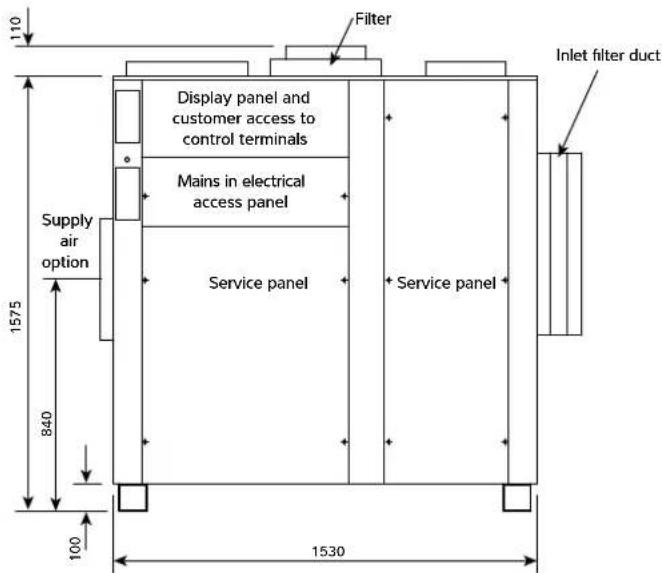
Front view

Side view
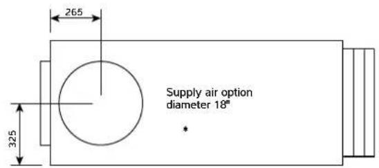
Bottom view (base)

DT4A, DT4B EF Configuration
Standard LPHW water connections 28mm copper stubs
Upgraded LPHW water connections 35mm copper stubs
Pool water connections 1" PVC stubs
Drain 34 " BSPM stub
* See duct dimension data

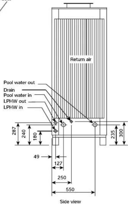

DT4A, DT4B ER Configuration
Standard LPHW water connections 28mm copper stubs
Upgraded LPHW water connections 35mm copper stubs
Pool water connections 1" PVC stubs
Drain = 3/4 BSPM stub
* See duct dimension data
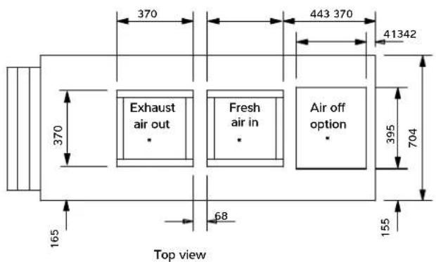
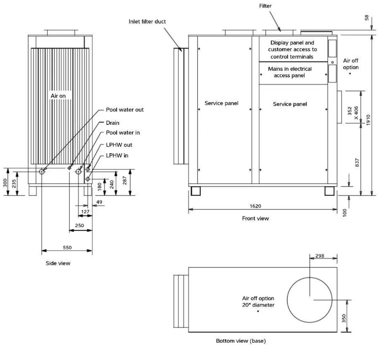

DT6A, DT6B, DT8B EF Configuration
Standard LPHW water connections 28mm copper stubs Upgraded LPHW water connections 35mm copper stubs Pool water connections 1" PVC stubs
Drain 34 " BSPM stub * See duct dimension data

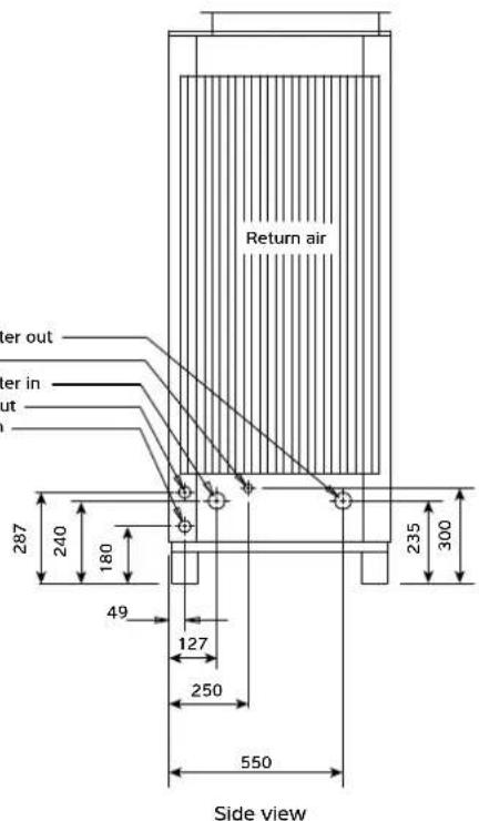

DT6A, DT6B, DT8B ER Configuration
Standard LPHW connections 28mm copper stubs Upgraded LPHW connections 35mm copper stubs
Pool water connections 1" PVC stubs
Drain 34 " BSPM stubs
* See duct dimension data


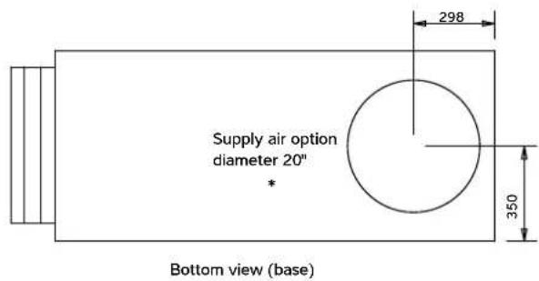
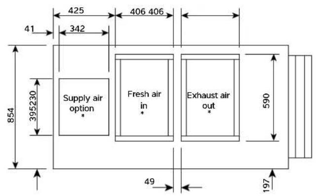
DT10B, DT12B EF Configuration
Standard LPHW connections 35mm copper stubs Upgraded LPHW connections 35mm copper stubs Pool water connections 1½" PVC stubs Drain ¾" BSPM stubs * See duct dimension data
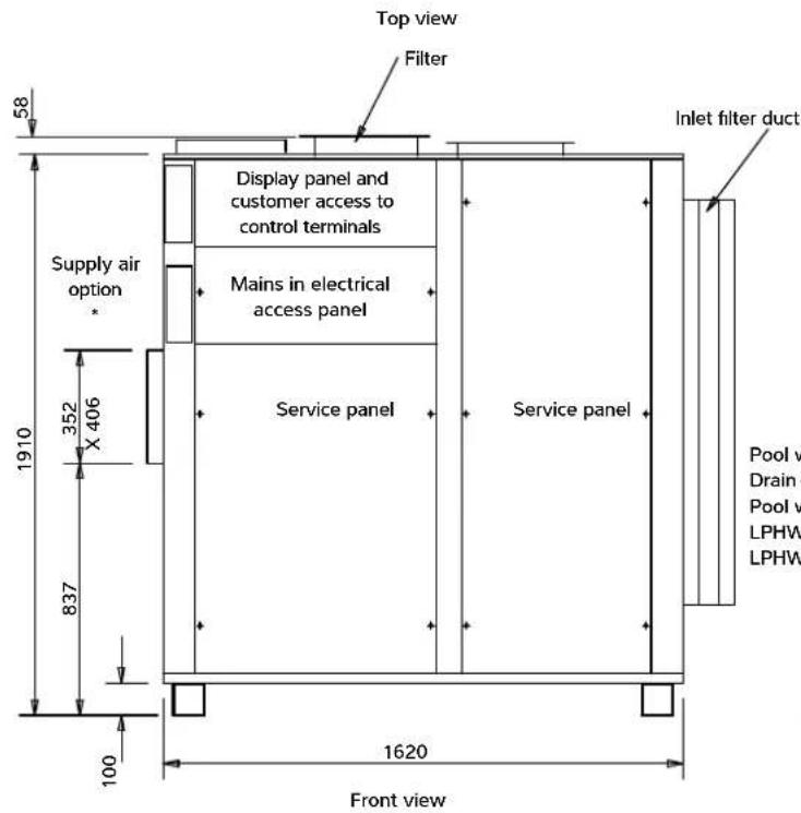
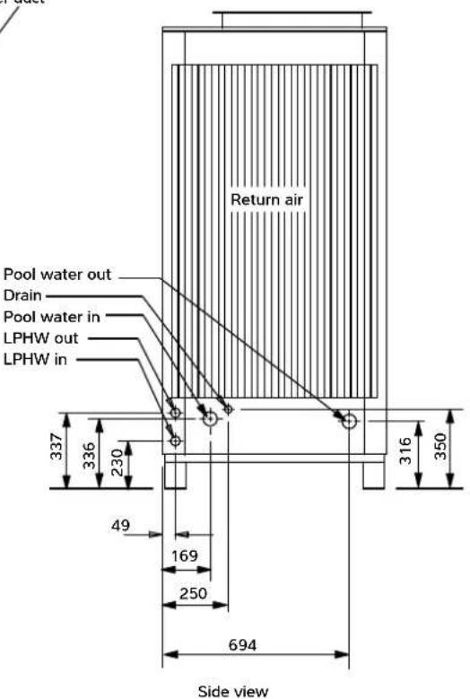

DT10B, DT12B ER Configuration
Standard LPHW connections 35mm copper stubs Upgraded LPHW connections 35mm copper stubs
Pool water connections 1½" PVC stubs Drain ¾" BSPM stub
* See duct dimension data
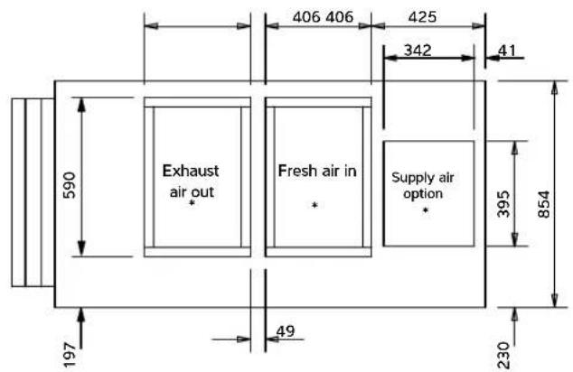
Top view


Bottom view (base)
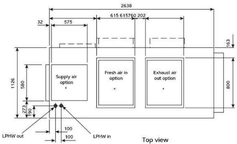
DT14B, DT16B EF Configuration
Pool water connections 1½ BSPM
Standard LPHW connections = 1½ BSPM
Upgraded LPHW connections = 2 BSPM
Drain = 3/4 BSPM
* See duct dimension data

Side view

DT14B, DT16B ER Configuration
Pool water connections 1½ BSPM
Standard LPHW connections = 1½ BSPM
Upgraded LPHW connections = 2 BSPM
Drain = 3/4 BSPM
* See duct dimension data
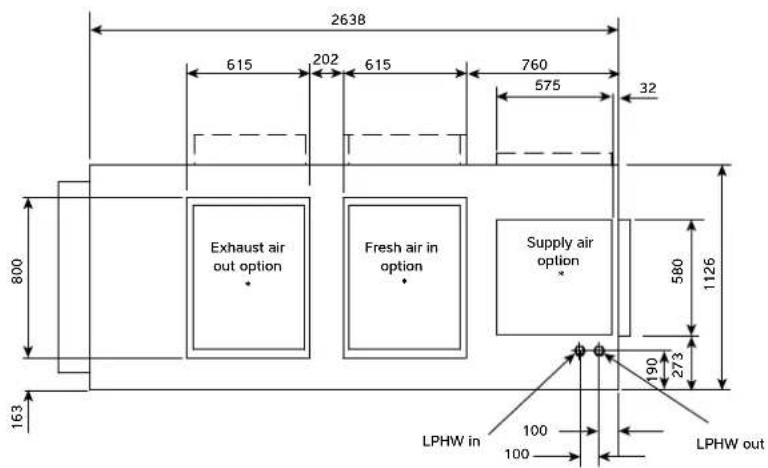
Top view

Side view
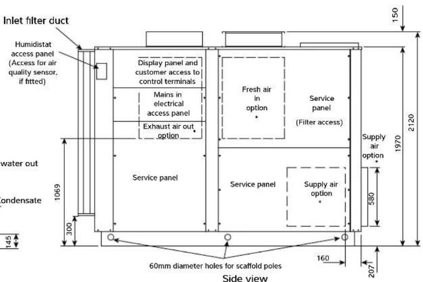

Bottom view (base)
Delta model 1 and 2 duct dimension data

Delta model 4 duct dimension data
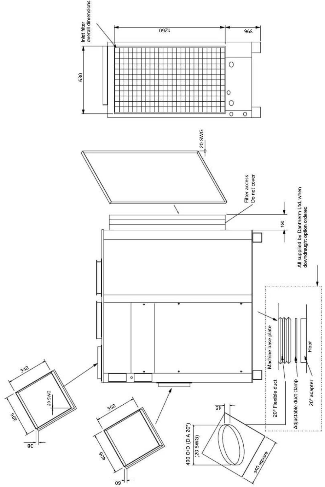
Delta model 6 and 8 duct dimension data
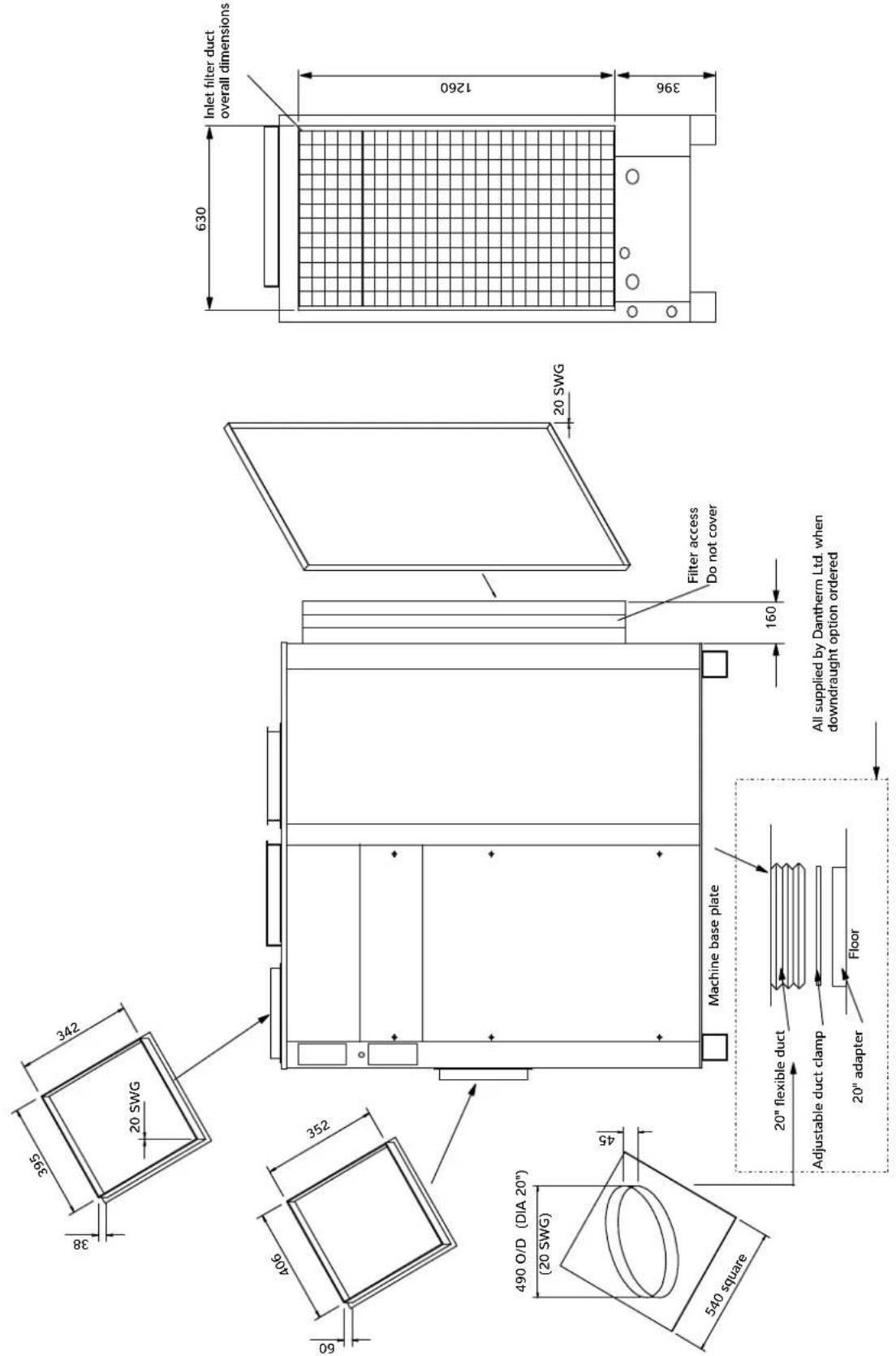
Delta model 10 and 12 duct dimension data
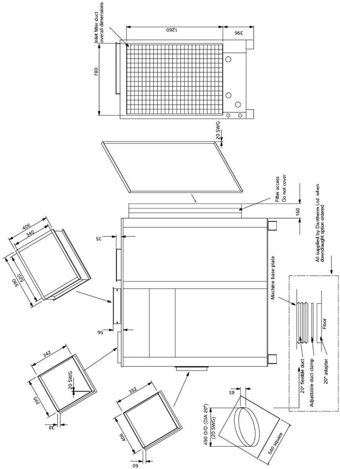
Delta model 14 & 16 duct dimension data

7.0 DELTA CONFIGURATIONS
The Delta can be supplied in a range of physical configurations.
DT1 & DT2
| Type (tick 1)230V - 1 phase 400V - 3 phase | Main fan outlet (tick 1) | Options (tick all that apply) | ||||
| Delta 1A | ☐ | Delta 1B | ☐ | SO | ☐ | A Wooden Crate |
| Delta 2A | ☐ | Delta 2B | ☐ | TO | ☐ | B Fan pressure monitoring |
| BO | ☐ | C Filter pressure monitoring | ||||
| D Air quality sensor | ||||||
| E Upgraded LPHW | ||||||
| F Duct kit | ||||||
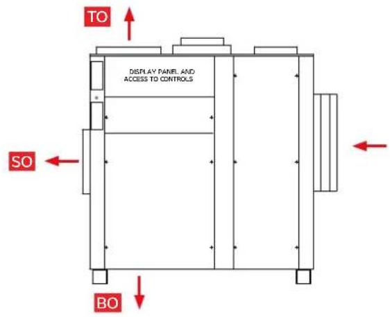
DT4, DT6, DT8, DT10, & DT12
| Type (tick 1)230V - 1 phase 400V - 3 phase | Orientation (tick 1) | Main fan outlet (tick 1) | Options (tick all that apply) | |||||
| Delta 4A | ☐ | Delta 4B | ☐ | EF | ☐ | SO | ☐ | A ☐ Wooden crate |
| Delta 6A | ☐ | Delta 6B | ☐ | ER | ☐ | TO | ☐ | B ☐ Fan pressure monitoring |
| Delta 8B | ☐ | BO | ☐ | C ☐ Filter pressure monitoring | ||||
| Delta 10B | ☐ | D ☐ Air quality sensor | ||||||
| Delta 12B | ☐ | E ☐ Upgraded LPHW | ||||||
| F ☐ Duct kit | ||||||||
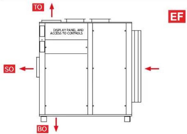

DT14 & DT16
| Type (tick one)400V - 3 Phase | Orientation(tick one) | Main fan outlet(tick one) | Damper position(tick one) | Options(tick all that apply) |
| Delta 14B | A □ Wooden crate | |||
| Delta 16B | BO □FO □RO □ | DR □ | B □ Fan pressure monitoringC □ Filter pressure monitoringD □ Air quality sensorE □ upgraded LPHWF □ duct kit |
Options
A □ Wooden crate
B □ Fan pressure monitoring
C □ Filter pressure monitoring
D □ Air quality sensor
E Upgraded LPHW
F duct kit
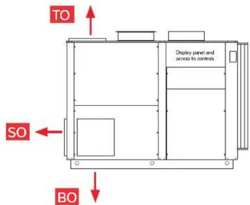

(Side view)
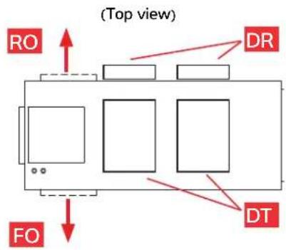


8.0 WARRANTY CONDITIONS
One year manufacturer's warranty is valid from the date of commissioning or 18 months from delivery, whichever is sooner.
Where commissioning is provided in the UK and Ireland, this must be carried out by factory trained and approved personnel.
The following exclusions apply to the Warranty given by Dantherm Ltd. No claims will be accepted if :
- The heat pump is installed in any way that is not in accordance with the current procedures as defined by Dantherm Ltd.
- The heat pump has not been maintained in accordance with service requirements in section 4.1 Regular Planned Maintenance.
- The heat pump has been worked upon or is adjusted by anyone other than a person authorised to do so by Dantherm Ltd.
- The heat pump is incorrectly sized for the application.
- The water flow through the machine is outside the specified limits.
| Acidity pH pH 7.8 - 7.2 | ||
| Total Alkalinity, as CaCO3 ppm 120 - 80 | ||
| Total Hardness, as CaCO3 ppm 250 - 150 | ||
| Total Dissolved Solids ppm 1000 | ||
| Maximum Salt Content ppm 8000 | ||
| Free Chlorine Range ppm Domestic 2 - 1 | ||
| Free Chlorine Range ppm Commercial 6 - 3 | ||
| Superchlorination max 30ppm for 24 hrs | ||
| Bromine | ppm 5 - 2 | |
| Baquacil | ppm 50 - 25 | |
| Ozone | ppm Max 0.9 | |
| Maximum Copper Content ppm 1 | ||
| Aquamatic Ionic Purifier | ppm Max 2 |
- The water pH level and/or chemical balance is outside the following limits:
- The heat pump has suffered frost damage.
- The electrical supply is insufficient or in any way incorrect.
- The fan amps and duct pressure are outside the specified limits.
- The air flow to and from the machine is outside the specified limits.
- Corrosion is present due to poor air quality that has not been attended to.
If in doubt or if advice is required please contact the Dantherm Group UK Service Department by calling 01621 856611 (option 4) or emailing service.department@dantherm.com
Note: The Reply Paid Warranty Registration Card must be returned, to ensure that the correct warranty is given. If you do not find a Registration Card with your heat pump please contact the Dantherm Group UK Service Department giving your name, address and serial number of your heat pump. A card will be sent to you for completion.
Please give MODEL NUMBER and SERIAL NUMBER of your heat pump when making technical or service enquiries. This will assist in correct diagnosis and ensure service can be provided with the minimum delay.
In order to comply with European F-Gas regulations, it is necessary for hermetically sealed systems with more than 6kg refrigerant to be leak tested annually.
The operator of the heat pump is responsible for seeing that the test is carried out.
For heat pumps affected see Datasheet. A sample log sheet can be seen below.
Dantherm Ltd. is an F-Gas registered company. Certificate number REF1011570.
| GENERAL INFORMATION | ||||
| Plant name Serial number | ||||
| Location of plant | ||||
| Plant operator1 | ||||
| Operator contact2 | ||||
| Refrigerant type Refrigerant quantity installed (kg) | ||||
| Plant manufacturer Dantherm Ltd Year of installation | ||||
| REFRIGERANT ADDITIONS | ||||
| Date | Engineer3 | Amount added kg | Reason for addition | |
| Company Name | ||||
| REFRIGERANT REMOVALS | ||||
| Date | Engineer | Amount removed kg | Reason for removal What done with recovered refrigerant | |
| Company Name | ||||
| NAME AND ADDRESS OF RECYCLING OR RECLAMATION FACILITY | Certificate number if applicable | |||
| LEAK TESTS | ||||
| Date | Engineer | Test result Follow up action required | ||
| Company Name | ||||
| FOLLOW UP ACTIONS | ||||
| Date | Engineer | Related to test on Actions taken | ||
| Company Name | ||||
| TESTING OF AUTOMATIC LEAK DETECTION SYSTEM (IF FITTED) | ||||
| Date | Engineer | Test result Comments | ||
| Company Name | ||||
1 Name and address of company operating plant.
2 Contact details of operator's nominated person responsible for F-Gas compliance.
3 Company and technician carrying out work, with details to provide evidence of compliance.
SD675650 ISSUE 6 M172 DELTA
IMPORTANT The company carrying out refrigerant checking and removals, and the owner of the equipment need to keep records for FIVE YEARS.
When this heat pump is decommissioned the refrigerant gas is to be recovered in accordance with current environmental legislation.
danthermgroup.co.uk
Dantherm Ltd.
Unit 12, Galliford Road
Maldon CM9 4XD
United Kingdom
+44 (0)1621 856 611

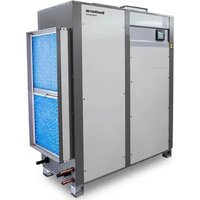


- HEALTH AND SAFETY WARNING
- CONTENTS
- FEATURES OF THE DELTA RANGE
- HOW THE DELTA SYSTEM WORKS
- HOW THE AIR FLOWS THROUGH THE DELTA
- HOW TO USE THE DELTA
- TOUCHSCREEN USER INTERFACE
- Home screens
- First home screen
- Second home screen
- Pool hall relative humidity (%RH)
- Key to lights
- Pool hall air temperature (°C)
- Pool water temperature (°C)
- Swimming icon
- Indicator lights
- Defrost light
- Fault light
- Alarm light
- Standby switch
- Fresh air setting
- Occupied/Unoccupied override
- User settings
- Function button
- Air-conditioning mode button
- Air/Water priority button
- Service engineer settings
- HUMIDITY AND TEMPERATURE SETTINGS
- Unless the Delta has been specifically chosen for the purpose, do not operate with the air temperature below the water temperature when the cover is removed.
- OCCUPIED AND UNOCCUPIED
- Going away for extended periods
- DATA ENTRY
- SECURITY MODE
- USER SETTINGS
- INSERT THE PIN AND PRESS THE ARROW
- Settings
- CONTROLLER CLOCK
- PRESS SET CLOCK
- TIME CLOCK
- Home icon
- ALARMS
- Arrow icon
- SET POINTS AND SWITCHES
- DANCE HALL MODE
- LANGUAGE
- USER SECURITY
- USER PIN:
- Security Mode Disabled
- CHANGE WEBGATE PASS
- WEBGATE PASSWORD:
- DATA MONITORING
- ADVANCED SETTINGS
- WARNING
- Advanced Settings
- OFFSETS
- Frost Protection
- CUSTOMER TIMERS
- SCREEN SETTINGS
- FACTORY RESET
- NETWORK SETTINGS
- BMS SETTINGS
- After changing any of the above settings, restart the PLC/Delta to save and apply the new settings.
- PLC ETHERNET SETTINGS
- MORE OPTIONS
- REMOTE ACCESS TO THE DELTA TOUCHSCREEN
- Local Area Network Connection
- Ports to be forwarded
- Using an Android/iOS mobile device
- If the Delta is ONLY to be accessed when the device is connected to the SAME network as the Delta:
- If the Delta is to be accessed when the device could be anywhere:
- Using an ActiveX web browser on a networked computer
- For first time setup instructions, see right.
- If the Delta is ONLY to be accessed when the computer is connected to the SAME network as the Delta:
- ActiveX browser first time set up procedure
- Whichever method is used, when the Delta Controller appears:
- INSTALLATION
- Installation summary
- Unloading and unpacking
- Items included with Delta
- Positioning
- Siting
- Summary of connections and services
- Ductwork
- Plumbing
- Electrical
- Remote interfaces (if required)
- After installation
- Ongoing maintenance
- AIR FLOW (POOL HALL AIR)
- FRESH AIR AND EXHAUST AIR
- Notes
- PLUMBING INSTALLATION
- Pool water
- Condensate drain
- LPHW plumbing
- Important general points
- Determining water flow
- a. Flow Meter Method (see Fig 3)
- b. Differential Pressure Method (see Fig 3)
- Setting up the differential
- ELECTROLYTIC CORROSION IN SWIMMING POOLS
- ELECTRICAL CONNECTIONS
- ELECTRICAL INSTALLATION
- Electrical safety
- Protected supply
- Inconsistent electrical supply
- Correct cable sizing
- VOLT FREE TERMINALS AND REMOTE ACCESS
- "Boiler Go" demand – terminals 6/7
- "Pool Pump Run" demand – terminals 8/9
- "Time clock override" (remote Occupied/Unoccupied) – control terminals 10/11
- "Remote On/Off" – terminals 12/13
- Fire Alarm interface – terminals 14/15
- "Remote Damper" control – terminals 19/20
- "Volt free" status signals – terminals 21/22/23/24
- Swimming pool filtration pump time clock
- Advanced Frost Protection
- AIR QUALITY SENSOR IF OPTION FITTED (KIT D)
- In the interests of safety, the position of the shorting plug should only be changed by an electrician due to the danger of electric shock.
- NETWORK CONNECTION
- BMS CONNECTION
- (BUILDING MANAGEMENT SYSTEM)
- OPTIONAL REMOTE SENSOR BOX
- Replace covers
- AFTER INSTALLATION
- Pre-commissioning checklist
- Initial start-up
- Commissioning
- Pool hall and plant room
- Ductwork and air flow
- LPHW
- Heat pump
- Controls
- Commissioning report
- Operator handover
- MAINTENANCE
- Operations carried out during a planned maintenance visit are as follows:
- Frequencies recommended are as follows:
- Model Light/Medium use Heavy use
- CIRCUIT DIAGRAMS
- LPHW HEATING DATA - DELTA WITH UPGRADED AIR HEATER
- DIMENSIONS
- DT1A, DT1B, DT2A, DT2B EF Configuration
- DT4A, DT4B EF Configuration
- DT4A, DT4B ER Configuration
- DT6A, DT6B, DT8B EF Configuration
- DT6A, DT6B, DT8B ER Configuration
- DT10B, DT12B EF Configuration
- DT10B, DT12B ER Configuration
- DT14B, DT16B EF Configuration
- DT14B, DT16B ER Configuration
- DELTA CONFIGURATIONS
- DT14 & DT16
- Options
- WARRANTY CONDITIONS
- Dantherm Ltd.
Brand : Calorex
Model : Delta
Category : Air conditioner