
ANT24-0800 - TV Antenna D-LINK - Free user manual and instructions
Find the device manual for free ANT24-0800 D-LINK in PDF.


| Product Type | Outdoor/Indoor TV Antenna |
| Brand | D-Link |
| Model | ANT24-0800 |
| Frequency Range | VHF (174-230 MHz) / UHF (470-862 MHz) |
| Gain | 8 dBi |
| Impedance | 75 Ohm |
| Polarization | Linear Horizontal |
| Dimensions (L x W x H) | 400 mm x 300 mm x 50 mm |
| Weight | 0.5 kg |
| Cable Length | 5 m (coaxial) |
| Connector Type | F-type female |
| Mounting | Wall bracket or pole mount (included) |
| Weather Resistance | IP54 (splash-proof) |
| Operating Temperature | -20°C to 60°C |
| Power Supply | Passive (no external power needed) |
| Directionality | Directional |
| Color | Black / Grey |
| Compliance | RoHS, CE |
| Package Contents | Antenna, mounting kit, 5m coaxial cable, manual |
| Maintenance | Clean with dry cloth; avoid abrasive cleaners |
| Safety Warning | Disconnect from receiver before cleaning |
| Spare Parts Availability | Contact D-Link support for replacements |
Frequently Asked Questions - ANT24-0800 D-LINK
User questions about ANT24-0800 D-LINK
0 question about this device. Answer the ones you know or ask your own.
Ask a new question about this device
Download the instructions for your TV Antenna in PDF format for free! Find your manual ANT24-0800 - D-LINK and take your electronic device back in hand. On this page are published all the documents necessary for the use of your device. ANT24-0800 by D-LINK.
USER MANUAL ANT24-0800 D-LINK
natural_image
Collection of various electronic and medical sensor components including sensors, cables, and a D-Link device (no visible text or symbols)User's Guid
Version 3.00
ANT24-Series
ANT70-Series
D-Link Antenna Kits
D-Link Antenna-kit Installation Guide
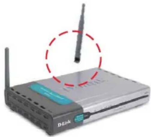
Step 1
Remove the default antenna.
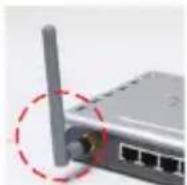
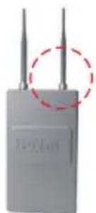
natural_image
Gray electronic device with two antennas and a red dashed circle highlighting the top-right corner (no visible text or symbols)Step 2
Connect the extension cable/antenna onto the external connector on device.
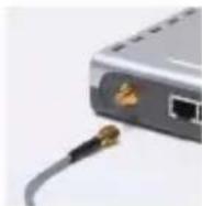
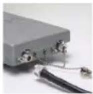
Step 3 (If needed)
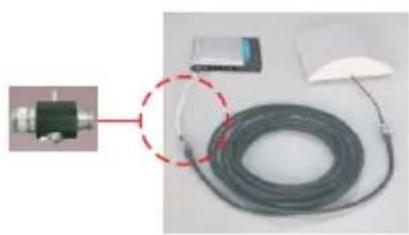
natural_image
Close-up of a mechanical device connected to a coiled cable and a small electronic device (no visible text or symbols)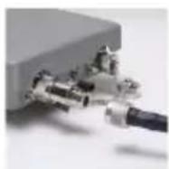
Install the surge protector. (You can install with optional ANT24 series low loss cables)
Note:
When install the surge protector between cables,
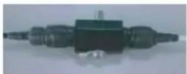
natural_image
Close-up of a black mechanical component with no visible text or symbolswrap the connectors as well. The lightning protection adaptor for grounding the antenna.
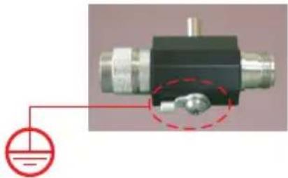
natural_image
Mechanical component with a red dashed circle highlighting a specific part, no visible text or symbolsWith Surge protector adaptor on an outdoor serial is attached to the lightning protection system (ground) of the building. All devices downstream are then protected by the ground from lightning strikes. It can protect your sensitive WLAN equipments from high voltage surges caused by discharge and transients at the antennas. It will be integrated in the cabling system between the antenna and the coax-cable and must have direct ground contact.
D-Link Antenna-kit Installation Guide
Surge protector Installation guide for outdoor antenna-kit
natural_image
Close-up of a hand holding a small mechanical component with a metallic fitting (no visible text or symbols)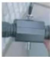
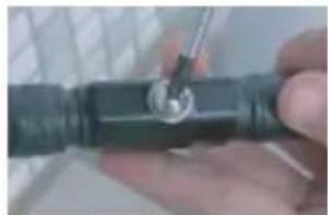
Step 1
loosen the screw from the surge protector.
natural_image
Close-up of a hand holding a small metallic tool interacting with a dark cylindrical object (no visible text or symbols)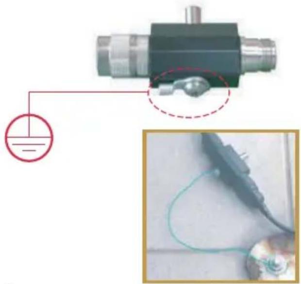
natural_image
Close-up of a mechanical component with a red dashed circle highlighting a small metallic part, and an inset image showing a cable being held (no text or symbols visible)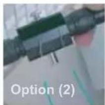
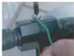
natural_image
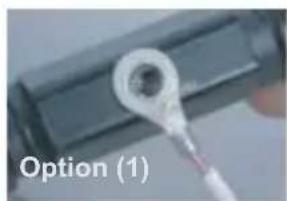
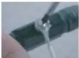
Close-up of a hand holding a black mechanical component with a green wire, no visible text or symbolsStep 2 get a normal conductive copper wire with 2 sides stripped long enough to be conductive, these wires can lead high voltage surges into the grounding.
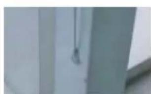
natural_image
Exterior view of a modern office building (no signage)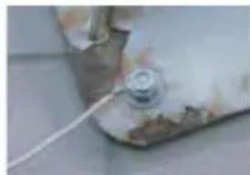
natural_image
Close-up of a mechanical component with a small cylindrical part attached to a surface, no visible text or symbols.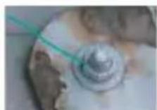

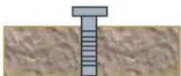
Ground
Step 3 find a conductive material nearby the antenna installation sites, connect another end of the wire into position, there are several options:
(1) Use a long screw to stick into the ground tightly, connect another wire onto.
(2) fix or solder another end of wire onto a steel material/ bar under steel construction, such as wall for buildings, railings or other conductive materials which set up from the ground.
Remark:
(1) for the ground screw you use, we suggest the longer (deeper into ground) the better performance it has.
(2) please use a copper wire with diameter at least from 2.0mm, the thicker the diameter, the higher voltage it can sustain.
Regulations
D-Link WLAN Antenna-Kit
Extended range differentiation for FCC/CE regulated regions
CE ETSI EN 300 328 regulated European Union (EU) regions
Based on ETSI EN 300 328, the system device and its antenna Emitted Isotropic Radiated Power (EIRP) are limited to operate within a 20dBm gain. The range extension provided by the antenna kit should comply with the restrictions set by the EU.
FCC regulated regions (US, Canada, etc.)
Using the same antenna-kit in FCC-regulated regions, the extended range may extend farther than CE-regulated antennas due to a higher output power allowance (FCC limits EIRP emissions to 36dBm).
The usage of high gain antennas must be properly set to comply with EU regulations, and additional consideration should be made to avoid potential health hazard. Consult a professional installer for every occasion of application.
Outdoor Installations
To fully benefit from D-Link's extensive range of quality outdoor antennas, please note that they should be installed by a professional and must comply with the Europe Union CE wireless radio frequency output power. Cable length will affect the antenna gain dramatically.
EIRP limitaton:
| 2.4GHz~2.5GHz 5.15GHz~5.35GHz | 5.47~5.725 5.75GHz~5.875GHz | ||||
| ETSI | point to multi-point | 20dBm ave.23dBm peak. | 23dBm 30dBm | X | |
| point to point | |||||
| FCC | point to multi-point 36dBm 36dBm | 23dBm | X | ||
| point to point | 30+6(antenna gain) dBmthen above 30dBm, one dB outputpower reduced, then 3dB antenna gainincreased | 30+23(antenna gain)then above 30dBm, one dB output powerreduced, then 3dB antenna gain increased | |||

For outdoor use
EIRP = Effective, Isotropic Radiated Power
= Device Output Power + Antenna Gain - Cable Loss
Cable Loss
| Model Cable Type Length Interface | Cable loss (dB) @ 2.4GHz | Cable loss(dB) @5GHz | ||
| ANT24-CB03N LMR400 3m N plug to N | jack 1 1.75 | |||
| ANT24-CB06N LMR400 6m N plug to N | jack 1.85 | 2.7 | ||
| ANT24-CB09N LMR400 9m N plug to N | jack | 2.6 | 3.8 |
Note:
- The loss value includes two connectors (around 0.3\~0.4dB @ 2.4GHz, 0.39\~0.52dB@5GHz).
- The longer cable you use, the more attenuation it causes, therefore, the extended range might be shorten then a normal link with default cables.
- To comply with EU regulation, please use longer cables which can cause enough attenuation value.
- For more detail of connectors type, please refer to the appendix page.(P.30)
D-Link ANT24-0230 Indoor MIMO Antenna
Electrical specification
| Frequency Range | 2400~2500MHz |
| Impedance | 50 Ohms |
| VSWR | 1.92 Max. |
| Return Loss | -10 dB Maximum |
| Antenna Structure | Helis antenna |
| Peak Gain (w/o cable loss) | 2dBi |
| Admitted power | 1 W |
| Cable loss(1.5m) | 2dB@2.45GHz |
| E-Plane | 60 deg. |
| H-Plane | 360 deg. |
Environmental & Mechanical Characteristics
| Cable | RG-174 Coaxial Cable |
| Cable length | 1.5M |
| Cable color | Black, Yellow |
| Connector | SMA Plug Reverse |
| Antenna Material | ABS+PC |
| Operating Temp | -20°C~+65°C |
| Storage Temp | -30°C~+75°C |
| Color | Antenna:Black , silverBase:silver |
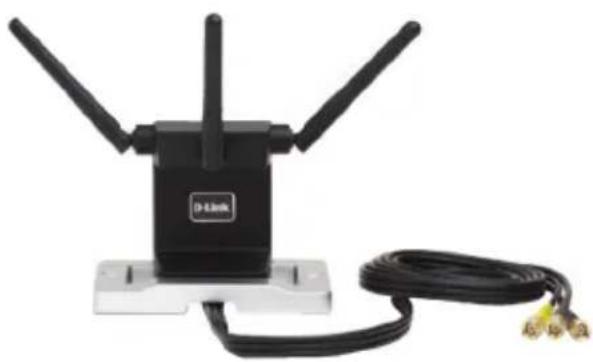
natural_image
Black D-Link wireless device with three antennas and a coiled cable (no text or symbols visible)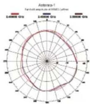
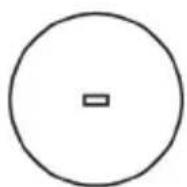
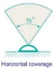
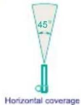
Horizontal coverage
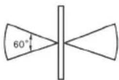
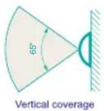
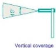
Vertical coverage
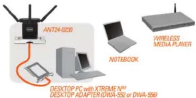
Package Contents:
- Xtreme N™ 2.4GHz aNTENNA
- Wall Mounting Kit
- Quick installation Guide
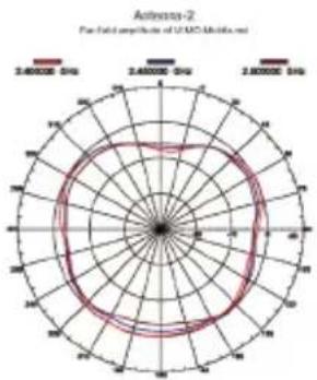
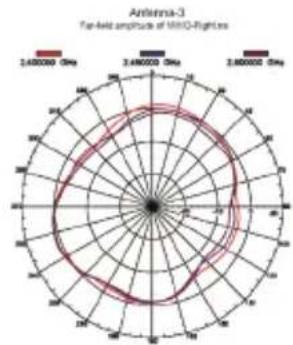
radar
| Angle | Value | |-------|-----------| | 0° | 2.48e6 | | 30° | 2.46e6 | | 60° | 2.44e6 | | 90° | 2.42e6 | | 120° | 2.40e6 | | 150° | 2.38e6 | | 180° | 2.36e6 | | 210° | 2.34e6 | | 240° | 2.32e6 | | 270° | 2.30e6 | | 300° | 2.28e6 | | 330° | 2.26e6 | | 360° | 2.24e6 |D-Link ANT24-0401 Ceiling Mount Antenna
Electrical specification
| Frequency band | 2400-2500MHz |
| Antenna gain | 2.5 - 3.7 dBi |
| VSWR | 2.0 max |
| Polarization | Linear vertical |
| HPBW / H-plane | 360 |
| HPBW / E-plane | 58°~75° |
| Impedence | 50 Ohms |
| Dimensions | ø132x42 mm |
| Weight | 110g without joint |
Environmental & Mechanical Characteristics
| Temperature -10°C to 55°C | |
| Humidity 100% @ 25 C | * |
| Lightning protection DC ground | |
| Radome color white | |
| Radome material ABS | |
| Weight 100gw | |
| Dimensions 132 x 42 mm | |
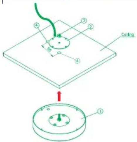
Installation Note:
- Carefully remove the antenna from the package.
- Take out the Washer (1 pcs) from the package
- Take out the Flange washer (1 pcs) as well.
- Drill 2 holes through the ceiling board, one to fix the antenna main body with wacher, another for the antenna SMA connector linked onto extension cable which is included within the package.
Package Contents:
- ANT24-0401 Antenna
- Extension Cable (2M)
- Mounting Kit
- Quick Installation Guide

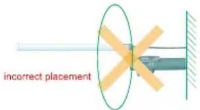
incorrect placement
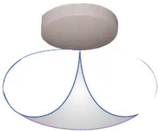
natural_image
Abstract 3D geometric shape with curved lines and a top circular feature (no text or symbols)
Horizontal coverage
Overlook
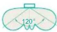
Vertical coverage
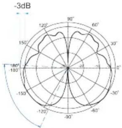
radar
| Angle | Value | |-------|-------| | 0° | -20 | | 30° | -25 | | 60° | -30 | | 90° | -35 | | 120° | -40 | | 150° | -45 | | 180° | -50 | | 210° | -45 | | 240° | -40 | | 270° | -35 | | 300° | -30 | | 330° | -25 | | 360° | -20 | | 390° | -15 | | 420° | -10 | | 450° | -5 | | 480° | 0 | | 510° | 5 | | 540° | 10 | | 570° | 15 | | 600° | 20 | | 630° | 25 | | 660° | 30 | | 690° | 35 | | 720° | 40 | | 750° | 45 | | 780° | 50 | | 810° | 45 | | 840° | 40 | | 870° | 35 | | 900° | 30 | | 930° | 25 | | 960° | 20 | | 990° | 15 | | 1020° | 10 | | 1050° | 5 | | 1080° | 0 | | 1110° | -5 | | 1140° | -10 | | 1170° | -15 | | 1200° | -20 | | 1230° | -25 | | 1260° | -30 | | 1290° | -35 | | 1320° | -40 | | 1350° | -45 | | 1380° | -50 | | 1410° | -45 | | 1440° | -40 | | 1470° | -35 | | 1500° | -30 | | 1530° | -25 | | 1560° | -20 | | 1590° | -15 | | 1620° | -10 | | 1650° | -5 | | 1680° | 0 | | 1710° | 5 | | 1740° | 10 | | 1770° | 15 | | 1800° | 20 |Vertical Pattern@2.45 GHz
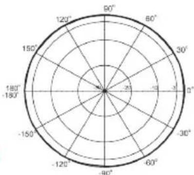
radar
| Angle | Value | |---|---| | 0° | -10 | | 30° | -15 | | 60° | -20 | | 90° | -25 | | 120° | -30 | | 150° | -35 | | 180° | -40 | | 210° | -45 | | 240° | -50 | | 270° | -55 | | 300° | -60 | | 330° | -65 | | 360° | -70 |Horizontal Pattern @2.45 GHz
D-Link ANT24-0500Indoor/Outdoor Omni-Directional Antenna
Electrical specification
| Frequency band | 2400-2500MHz |
| Antenna gain | 5.0 dBi |
| VSWR | 2.0 max |
| Polarization | Linear vertical |
| HPBW / H-plane | 360 |
| HPBW / E-plane | 32° |
| Impedence | 50 Ohms |
| Dimensions LxWxH | 19× 330mm |
| Weight | 180g without joint |
Environmental & Mechanical Characteristics
| Survival wind speed 180 km/hr |
| Temperature -40 C to +80 C |
| Humidity 100% @ 25 C |
| Lightning protection DC ground |
| Radome color Gray-white |
| Radome material Fiberglass |
| Radiator material Micro striple line |
| Weight 0.8kgw |
| Dimensions 330 x 19 mm |
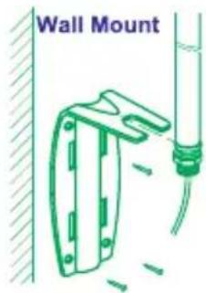
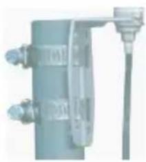
Pole Mount
natural_image
Exterior view of a mechanical or electrical component with no visible text or symbolsInstallation Note:
- use L-type mounting to fix with antenna
- use 4 plastic anchor with (4) screws to install the antenna onto the wall.
- use band clamp (2pcs) to fix the antenna on the pole.
Package Contents:
- ANT24-0500 Antenna
- Extension Cable (3m)
- Mounting Kit
- Quick Installation Guide
natural_image
Diagram of a satellite dish antenna with a central vertical axis and base mount (no text or symbols)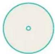
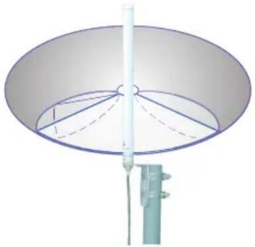
Horizontal coverage
Overlook
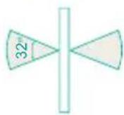
Vertical coverage
H-plane Co-polarization Pattern
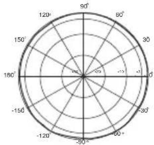
radar
| Angle (degrees) | Value | |---|---| | 0° | -15 | | 30° | -10 | | 60° | -7 | | 90° | -3 | | 120° | 0 | | 150° | 3 | | 180° | 6 | | 210° | 9 | | 240° | 12 | | 270° | 15 | | 300° | 18 | | 330° | 20 | The chart displays a polar coordinate system with angular positions in degrees and radial values representing magnitude or intensity. The data is plotted as a circle divided into three equal sectors for the polar plot. There are no labels or additional data series in this image.V-plane Co-polarization Pattern
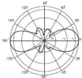
radar
| Angle (°) | Value | | --------- | ----- | | 0 | -20 | | 30 | -10 | | 60 | -5 | | 90 | 0 | | 120 | 5 | | 150 | 10 | | 180 | 15 | | 210 | 20 | | 240 | 15 | | 270 | 10 | | 300 | 5 | | 330 | 0 | | 360 | -5 |CAUTION:
Please always place the antenna vertically to the horizontal surface, not recommend to mount the antenna perpendicular to walls.
D-Link ANT24-0501 Indoor Omni-Directional Antenna
Electrical specification
| Frequency Range 2400~2500MHz | |
| Impedance 50Ω Normal | |
| VSWR 1.92 Max | |
| Return Loss -10 dB Maximum | |
| Antenna Structure Helis antenna | |
| Peak Gain ( w/o cable loss) 5dBi | |
| Admitted Power 1 W | |
| Cable loss( 1.5m) 2.1dB@2.45GHz | |
| E-Plane 36 deg. | |
| H-Plane 360 deg. | |
Physical Properties
| Cable RG-178 50Ω | |
| Cable length 1.5 M | |
| Cable color Gray | |
| Connector Reverse SMA plug | |
| Antenna Material | ABS, ABS+PC |
| Operating Temp | -20°C ~ +65°C |
| Storage Temp | -30°C ~ +75°C |
| Color | Antenna: Metallic gray and silverBase: Metallic gray |
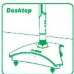
natural_image
Illustration of a desktop cleaning tool with a lever and base (no text or symbols)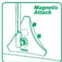
Package Contents
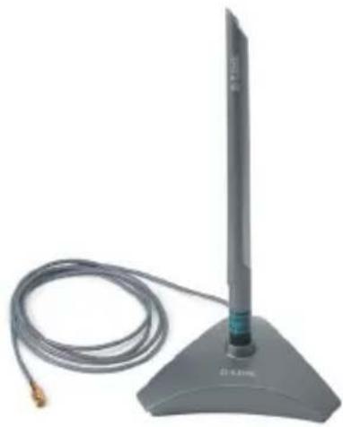
-One ANT24-0501 2.4GHz indoor 5dBi omni-directional Antenna with 1.5M extension cable and RP-SMA Jack connector
-One RP-SMA/ RP-TNC adaptor
-One registration card and international office guide
-Mounting kit includes:
-Two Crews
-Two plastic fixings
-One sticker
natural_image
Exterior view of a modern office building (no signage)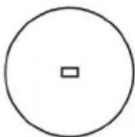
Horizontal coverage
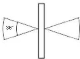
Vertical coverage
Far-field amplitude of D-link-5dBi-H-1020.nsi
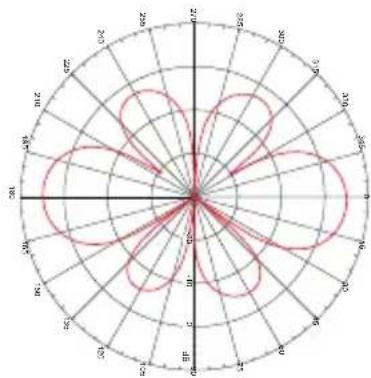
radar
| Angle (°) | Value | |---|---| | 0 | 0 | | 30 | 15 | | 60 | 30 | | 90 | 45 | | 120 | 60 | | 150 | 75 | | 180 | 90 | | 210 | 105 | | 240 | 120 | | 270 | 135 | | 300 | 150 | | 330 | 165 | | 360 | 180 | | 390 | 195 | | 420 | 210 | | 450 | 225 | | 480 | 240 | | 510 | 255 | | 540 | 270 | | 570 | 285 | | 600 | 300 | | 630 | 315 | | 660 | 330 | | 690 | 345 | | 720 | 360 | | 750 | 375 | | 780 | 390 | | 810 | 405 | | 840 | 420 | | 870 | 435 | | 900 | 450 | | 930 | 465 | | 960 | 480 | | 990 | 495 | | 1020 | 510 | | 1050 | 525 | | 1080 | 540 | | 1110 | 555 | | 1140 | 570 | | 1170 | 585 | | 1200 | 600 | | 1230 | 615 | | 1260 | 630 | | 1290 | 645 | | 1320 | 660 | | 1350 | 675 | | 1380 | 690 | | 1410 | 705 | | 1440 | 720 | | 1470 | 735 | | 1500 | 750 | | 1530 | 765 | | 1560 | 780 | | 1590 | 795 | | 1620 | 810 | | 1650 | 825 | | 1680 | 840 | | 1710 | 855 | | 1740 | 870 | | 1770 | 885 | | 1800 | 900 | | 1830 | 915 | | 1860 | 930 | | 1890 | 945 | | 1920 | 960 | | 1950 | 975 | | 1980 | 990 | | 2010 | 1015 | | 2040 | 1030 | | 2070 | 1045 | | 2100 | 1060 | | 2130 | 1075 | | 2160 | 1090 | | 2190 | 1105 | | 2220 | 1120 | | 2250 | 1135 | | 2280 | 1150 | | 2310 | 1165 | | 2340 | 1180 | | 2370 | 1195 | | 2400 | 1210 | | 2430 | 1225 | | 2460 | 1240 | | 2490 | 1255 | | 2520 | 1270 | | 2550 | 1285 | | 2580 | 1300 | | 2610 | 1315 | | 2640 | 1330 | | 2670 | 1345 | | 2700 | 1360 | | 2730 | 1375 | | 2760 | 1390 | | 2790 | 1405 | | Note: The data is in a format where the number of rows for each row corresponds to the value of the row in the chart. The values are estimated based on the formula 'a' and the number of rows for each row. There is only one data series labeled 'a'. The values are estimated based on the formula 'b'.Far-field amplitude of D-link-5dBi-v-1020.nsi
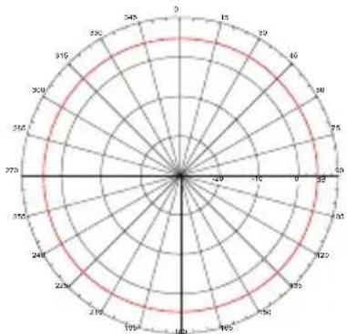
radar
| Angle (°) | Value | |-----------|-------| | 0 | 29 | | 30 | 345 | | 60 | 315 | | 90 | 280 | | 120 | 265 | | 150 | 270 | | 180 | 240 | | 210 | 215 | | 240 | 195 | | 270 | 180 | | 300 | 165 | | 330 | 150 | | 360 | 135 | | 390 | 120 | | 420 | 105 | | 450 | 90 | | 480 | 75 | | 510 | 60 | | 540 | 45 | | 570 | 30 | | 600 | 15 | | 630 | -15 | | 660 | -30 | | 690 | -45 | | 720 | -60 | | 750 | -75 | | 780 | -90 | | 810 | -105 | | 840 | -120 | | 870 | -135 | | 900 | -150 | | 930 | -165 | | 960 | -180 | | 990 | -195 | | 1020 | -210 | | 1050 | -225 | | 1080 | -240 | | 1110 | -255 | | 1140 | -270 | | 1170 | -285 | | 1200 | -300 | | 1230 | -315 | | 1260 | -330 | | 1290 | -345 | | 1320 | -360 | | 1350 | -375 | | 1380 | -390 | | 1410 | -405 | | 1440 | -420 | | 1470 | -435 | | 1500 | -450 | | 1530 | -465 | | 1560 | -480 | | 1590 | -495 | | 1620 | -510 | | 1650 | -525 | | 1680 | -540 | | 1710 | -555 | | 1740 | -570 | | 1770 | -585 | | 1800 | -600 | | Note: The data is in a grid format with 'Values' as the index of the data points. There is only one data series in this case. The values are explicitly labeled on the chart.D-Link ANT24-0501C Indoor Omni-Directional Antenna
Electrical specification
| Frequency Range 2400~2500MHz | |
| Impedance 50Ω Normal | |
| VSWR 1.92 Max | |
| Peak Gain 5dBi | |
| Admitted Power 1 W | |
| E-Plane 36 deg. | |
| H-Plane 360 deg. | |
Physical Properties
| Connector Reverse SMA plug | |
| Antenna Material ABS, ABS+PC | |
| Operating Temp -20°C ~ +65°C | |
| Storage Temp -30°C ~ +75°C | |
| Color Antenna: Metallic gray and silver | |
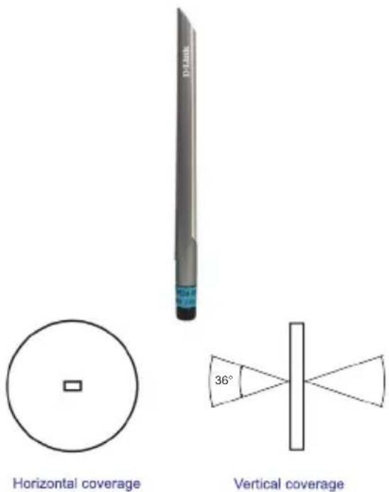
Package Contents
-One ANT24-0501C 2.4GHz 5dBi indoor omni-directional antenna with a RP-SMA plug connector
-One RP SMA/ RP TNC adapter
-One registration card and company contact guide
radar
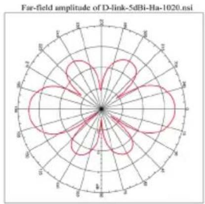
Far-field amplitude of D-link-5dBi-Ha-1020.nsi | Angle (degrees) | Far-field Amplitude | | :--- | :--- | | 0 | 0 | | 30 | 1.8 | | 60 | 4.2 | | 90 | 7.6 | | 120 | 10.8 | | 150 | 13.2 | | 180 | 15.6 | | 210 | 17.8 | | 240 | 19.2 | | 270 | 18.4 | | 300 | 16.6 | | 330 | 13.8 | | 360 | 10.8 | | 390 | 7.6 | | 420 | 4.2 | | 450 | 1.8 | | 480 | 0 | | 510 | -1.8 | | 540 | -4.2 | | 570 | -6.6 | | 600 | -9.0 | | 630 | -11.4 | | 660 | -13.8 | | 690 | -15.2 | | 720 | -14.4 | | 750 | -12.8 | | 780 | -10.8 | | 810 | -7.6 | | 840 | -4.2 | | 870 | -1.8 | | 900 | 0 | | 930 | 1.8 | | 960 | 4.2 | | 990 | 7.6 | | 1020 | 10.8 |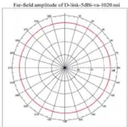
radar
Far-field amplitude of D-link-5dBi-va-1020.nsi | Angle (degrees) | Far-field Amplitude (dBm) | | :--- | :--- | | 0 | 0 | | 30 | 0 | | 60 | 0 | | 90 | 0 | | 120 | 0 | | 150 | 0 | | 180 | 0 | | 210 | 0 | | 240 | 0 | | 270 | 0 | | 300 | 0 | | 330 | 0 | | 360 | 0 | | 390 | 0 | | 420 | 0 | | 450 | 0 | | 480 | 0 | | 510 | 0 | | 540 | 0 | | 570 | 0 | | 600 | 0 | | 630 | 0 | | 660 | 0 | | 690 | 0 | | 720 | 0 | | 750 | 0 | | 780 | 0 | | 810 | 0 | | 840 | 0 | | 870 | 0 | | 900 | 0 | | 930 | 0 | | 960 | 0 | | 990 | 0 | | 1020 | 0 | | 1050 | 0 | | 1080 | 0 | | 1110 | 0 | | 1140 | 0 | | 1170 | 0 | | 1200 | 0 | | 1230 | 0 | | 1260 | 0 | | 1290 | 0 | | 1320 | 0 | | 1350 | 0 | | 1380 | 0 | | 1410 | 0 | | 1440 | 0 | | 1470 | 0 | | 1500 | 0 | | 1530 | 0 | | 1560 | 0 | | 1590 | 0 | | 1620 | 0 | | 1650 | 0 | | 1680 | 0 | | 1710 | 0 | | 1740 | 0 | | 1770 | 0 | | 1800 | 0 | | 1830 | 0 | | 1860 | 0 | | 1890 | 0 | | 1920 | 0 | | 1950 | 0 | | 1980 | 0 | | 2010 | 0 | | 2040 | 0 | | 2070 | 0 | | 2100 | 0 | | 2130 | 0 | | 2160 | 0 | | 2190 | 0 | | 2220 | 0 | | 2250 | 0 | | 2280 | 0 | | 2310 | 0 | | 2340 | 0 | | 2370 | 0 | | 2400 | 0 | | 2430 | 0 | | 2460 | 0 | | 2490 | 0 | | 2520 | 0 | | 2550 | 0 | | 2580 | 0 | | 2610 | 0 | | 2640 | 0 | | 2670 | 0 | | 2700 | 0 | | Note: The data is a time series visualization with 'Time' as the independent variable. The 'Amplitude' values are estimated based on the provided code.D-Link ANT24-0502
Indoor Omni-Directional Antenna
Electrical Specification
| Frequency range | 2400 MHz - 2500 MHz |
| Gain | 5.0dBi |
| VSWR | 2.0 : 1 Max |
| Polarization | Linear, vertical |
| HPBW/horizontal | 360° |
| HPBW/vertical | 40° |
| Downtilt | 0° |
| Power handling | 2 W (cw) |
| Impedance | 50 Ohms |
| Connector | RP SMA Plug |
Environmental & Mechanical Characteristics
| Temperature | -10°C to +55°C |
| Humidity | 95% @55°C |
| Radome color | Black |
| Radome material | ABS, UV resistant |
| Weight | 20 g |
| Dimensions | φ 13.5 x 177 mm |
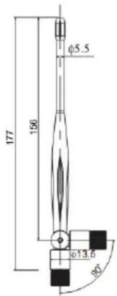
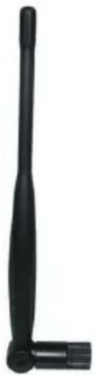
natural_image
Black right-handled antenna with a long shaft and base, isolated on white background (no text or symbols)H-plane Co-polarization Pattern
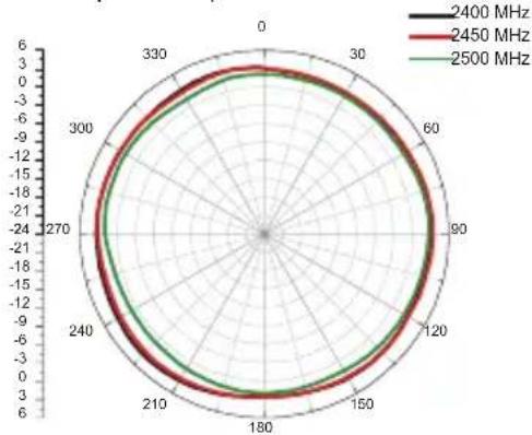
radar
| Angle | 2400 MHz | 2450 MHz | 2500 MHz | |---|---|---|---| | 0 | 6 | 6 | 6 | | 30 | 6 | 6 | 6 | | 60 | 6 | 6 | 6 | | 90 | 6 | 6 | 6 | | 120 | 6 | 6 | 6 | | 150 | 6 | 6 | 6 | | 180 | 6 | 6 | 6 | | 210 | 6 | 6 | 6 | | 240 | 6 | 6 | 6 | | 270 | 6 | 6 | 6 | | 300 | 6 | 6 | 6 | | 330 | 6 | 6 | 6 |V-plane Co-polarization Pattern
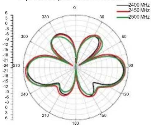
D-Link DWL-50AT Indoor Omni-Directional Antenna
Electrical specification
| Frequency band | 2400-2500MHz |
| Antenna gain | 5.0dBi Typical |
| VSWR | 2.0:1 Max. |
| Polarization | Linear |
| HPBW / H-plane | 360° |
| HPBW / E-plane | 30 degree |
| Impedence | 50 Ohms nominal |
| Dimensions HxWxD | 197 mm(length) |
| Weight | 29.5gw |
natural_image
D-Link router with antenna and antenna, no visible text or symbols on the device itselfInstallation:
- Remove the original antenna from your wireless device.
- Screw the DWL-50AT RP-SMA connector into your wireless device.
- Adjust the antenna to the suitable direction for extending the wireless coverage area.
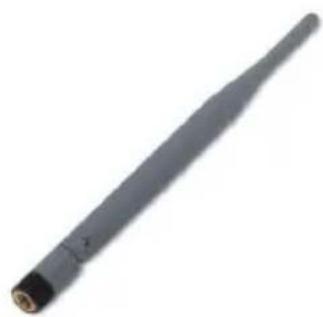
natural_image
Close-up of a black cylindrical electronic component with a pointed tip and small protrusions (no visible text or symbols)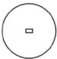
natural_image
Simple geometric diagram showing a circle with a centered square (no text or symbols)Horizontal coverage
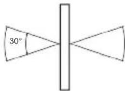
Vertical coverage
Far-field amplitude of C147-510017-A-V.nsi
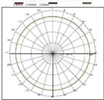
radar
| Angle | Value | |-------|-------| | 0° | 0 | | 30° | 1 | | 60° | 2 | | 90° | 3 | | 120° | 4 | | 150° | 5 | | 180° | 6 | | 210° | 7 | | 240° | 8 | | 270° | 9 | | 300° | 10 | | 330° | 11 | | 360° | 12 |Far-field amplitude of C147-510017-A-II.nsi
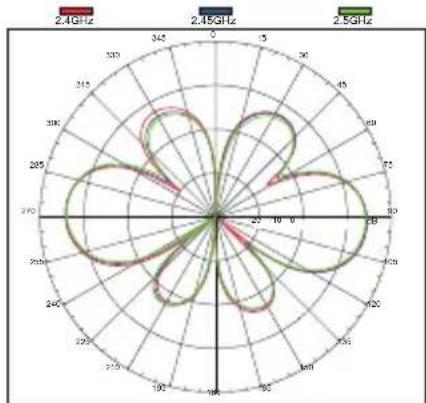
radar
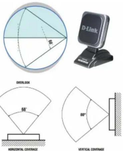
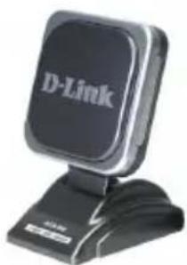
| Frequency | Value | |---|---| | 2.4GHz | 2.4 | | 2.45GHz | 2.45 | | 2.5GHz | 2.5 |D-Link ANT24-0600 Indoor Directional Antenna
Electrical specification
| Frequency Range 2400~2500MHz | |
| Impedance 50Ω Normal | |
| VSWR 1.92 Max | |
| Return Loss -10 dB Maximum | |
| Antenna Structure Pateh antenna | |
| Peak Gain ( w/o cable loss) 6.0 dBi @ 2.45GHz ( typical) | |
| Admitted Power 1 W | |
| Cable loss( 1.5m) 2.1dB@2.45GHz | |
| E-Plane 68° | |
| H-Plane 80° | |
Physical Properties
| Cable Filotex 50Ω | |
| Antenna Cover ABS | |
| Antenna Base PC | |
| Operating Temp -20°C ~ +65°C | |
| Storage Temp -30°C ~ +75°C | |
| Color | White |

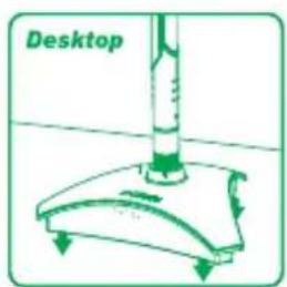
Desktop
Magnetic Attach
natural_image
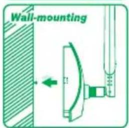
Black D-Link computer monitor with stand (no visible text or symbols on device body)Wall Mounting
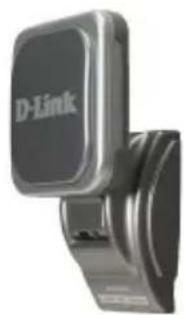
natural_image
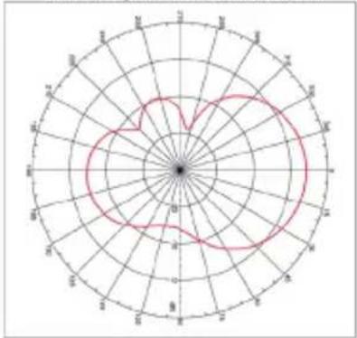
Close-up of a D-Link handheld device with metallic casing and black buttons (no visible text or symbols)Far-field amplitude of D-Link 6dBi H04.nsi
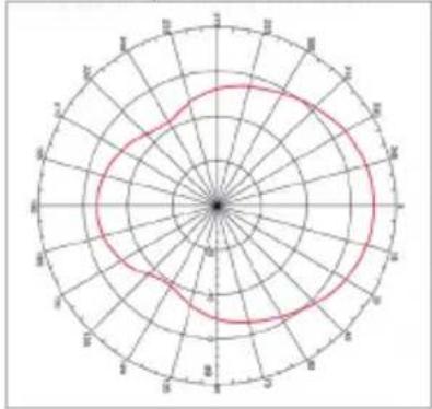
Far-field amplitude of D-Link 6dBi V04.nsi
radar
| Angle | Value | |---|---| | 0 | 0 | | 30 | 5 | | 60 | 10 | | 90 | 15 | | 120 | 20 | | 150 | 25 | | 180 | 30 | | 210 | 25 | | 240 | 20 | | 270 | 15 | | 300 | 10 | | 330 | 5 | | 360 | 0 | | 390 | -5 | | 420 | -10 | | 450 | -15 | | 480 | -20 | | 510 | -25 | | 540 | -30 | | 570 | -25 | | 600 | -20 | | 630 | -15 | | 660 | -10 | | 690 | -5 | | 720 | 0 | | 750 | 5 | | 780 | 10 | | 810 | 15 | | 840 | 20 | | 870 | 25 | | 900 | 30 | | 930 | 25 | | 960 | 20 | | 990 | 15 | | 1020 | 10 | | 1050 | 5 | | 1080 | 0 | | 1110 | -5 | | 1140 | -10 | | 1170 | -15 | | 1200 | -20 | | 1230 | -25 | | 1260 | -30 | | 1290 | -25 | | 1320 | -20 | | 1350 | -15 | | 1380 | -10 | | 1410 | -5 | | 1440 | 0 | | 1470 | 5 | | 1500 | 10 | | 1530 | 15 | | 1560 | 20 | | 1590 | 25 | | 1620 | 30 | | 1650 | 25 | | 1680 | 20 | | 1710 | 15 | | 1740 | 10 | | 1770 | 5 | | 1800 | 0 | | 1830 | -5 | | 1860 | -10 | | 1890 | -15 | | 1920 | -20 | | 1950 | -25 | | 1980 | -30 | | 2010 | -25 | | 2040 | -20 | | 2070 | -15 | | 2100 | -10 | | 2130 | -5 | | 2160 | 0 | | 2190 | 5 | | 2220 | 10 | | 2250 | 15 | | 2280 | 20 | | 2310 | 25 | | 2340 | 30 | | 2370 | 25 | | 2400 | 20 | | 2430 | 15 | | 2460 | 10 | | 2490 | 5 | | 2520 | 0 | | Note: The values in the 'Value' column are estimated based on the 'Radial Axis' and 'Angle' labels for the 'Radial Axis'. The 'Radial Axis' is labeled as 'radial position' (e.g., 'radial axis' corresponds to the angle). The 'Radial Axis' is labeled as 'angle position' (e.g., 'angle axis' corresponds to the angle). There is no additional data series present in this image. The label 'radial position' appears twice, likely indicating a different angular position or measurement. The value 'radial position' is explicitly labeled as 'radial position'.Package Contents
-One ANT24-0600 2.4GHz indoor 6dBi directional Antenna with 1.5 Filotex cable and RP-SMA Jack connector
-One RP-SMA/ RP-TNC adaptor
-One User's QIG
-Two Crews
-Two plastic fixings
-One sticker
D-Link ANT24-0700
Indoor Omni-Directional Antenna
Electrical specification
| Frequency Range 2400~2500MHz | |
| Impedance 50Ω Normal | |
| VSWR 1.92 Max | |
| Return Loss -10 dB Maximum | |
| Antenna Structure Helis antenna | |
| Peak Gain ( w/o cable loss) 7dBi | |
| Admitted Power 1 W | |
| Cable loss( 1.5m) 2.1dB@2.45GHz | |
| E-Plane 24 deg. | |
| H-Plane 360 deg. | |
Physical Properties
| Cable RG-178 50Ω | |
| Cable length 1.5 M | |
| Cable color Gray | |
| Connector Reverse SMA plug | |
| Antenna Material ABS, ABS+PC | |
| Operating Temp | -20°C ~ +65°C |
| Storage Temp | -30°C ~ +75°C |
| Color | Antenna: Metallic gray and silverBase: Metallic gray |
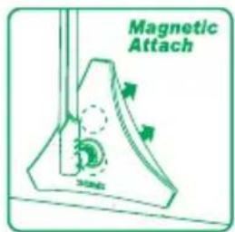
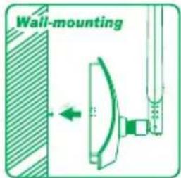
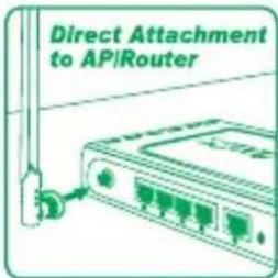
Package Contents
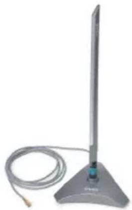
-D-Link ANT24-0700 2.4GHz Omni-Directional Indoor Antenna
-SMA to TNC Adapter
-Magnetic Base with 1.5m Extension Cable
-Mounting Kit
-Installation Guide
natural_image
Exterior view of a modern office building (no signage)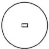
Horizontal coverage
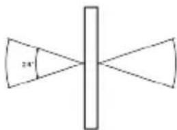
Vertical coverage
Far-field amplitude of D-link-7dBi-H1-1020.nsi
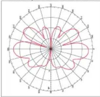
radar
| Sector | Value | |---|---| | M | 0.5 | | N | 0.7 | | H | 0.8 | | S | 0.6 | | B | 0.4 | | C | 0.3 | | D | 0.2 | | W | 0.1 | | H | 0.9 | | V | 0.4 | | S | 0.5 | | E | 0.6 | | B | 0.7 | | C | 0.8 | | D | 0.9 | | H | 1.0 | | W | 0.5 |Far-field amplitude of D-link-7dBi-v-1020.nsi
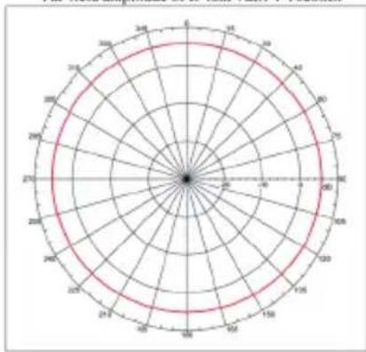
radar
| Angle (degrees) | Value | | :--- | :--- | | 0 | 0 | | 30 | 0 | | 60 | 0 | | 90 | 0 | | 120 | 0 | | 150 | 0 | | 180 | 0 | | 210 | 0 | | 240 | 0 | | 270 | 0 | | 300 | 0 | | 330 | 0 | | 360 | 0 | | 390 | 0 | | 420 | 0 | | 450 | 0 | | 480 | 0 | | 510 | 0 | | 540 | 0 | | 570 | 0 | | 600 | 0 | | 630 | 0 | | 660 | 0 | | 690 | 0 | | 720 | 0 | | 750 | 0 | | 780 | 0 | | 810 | 0 | | 840 | 0 | | 870 | 0 | | 900 | 0 | | 930 | 0 | | 960 | 0 | | 990 | 0 | | 1020 | 0 | | 1050 | 0 | | 1080 | 0 | | 1110 | 0 | | 1140 | 0 | | 1170 | 0 | | 1200 | 0 | | 1230 | 0 | | 1260 | 0 | | 1290 | 0 | | 1320 | 0 | | 1350 | 0 | | 1380 | 0 | | 1410 | 0 | | 1440 | 0 | | 1470 | 0 | | 1500 | 0 | | Note: The 'Value' in the 'Values' column is the same as the 'Radial Line' for all angles. There is only one data series in this case. |D-Link ANT24-0700C Indoor Omni-Directional Antenna
Electrical specification
| Frequency Range 2400~2500MHz | |
| Impedance 50Ω Normal | |
| VSWR 1.92 Max | |
| Return Loss 10 dB Maximum | |
| Antenna Structure Helis antenna | |
| Peak Gain (w/o cable loss) 7dBi | |
| Admitted Power 1 W | |
| Cable loss(1.5m) 2.1dB@2.45GHz | |
| E-Plane 24 deg. | |
| H-Plane 360 deg. | |
Physical Properties
| Cable RG-178 50Ω | |
| Cable length 1.5 M | |
| Cable color Gray | |
| Connector Reverse SMA plug | |
| Antenna Material | ABS, ABS+PC |
| Operating Temp | -20°C ~ +65°C |
| Storage Temp | -30°C ~ +75°C |
| Color | Antenna: Metallic gray and silverBase: Metallic gray |
Package Contents
-One ANT24-0700C 2.4GHz 7dBi indoor omni-directional antenna with a RP-SMA plug connector
-One RP SMA/ RP TNC adapter
-One registration card and company contact guide
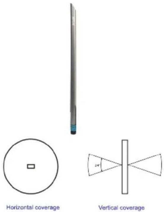
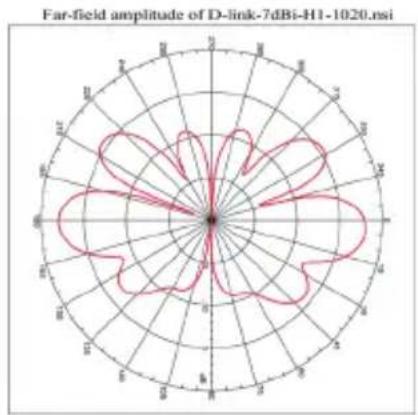
radar
Far-field amplitude of D-link-7dBi-H1-1020.nsi | Angle (degrees) | Far-field amplitude | | :--- | :--- | | 0 | 0 | | 30 | 0 | | 60 | 0 | | 90 | 0 | | 120 | 0 | | 150 | 0 | | 180 | 0 | | 210 | 0 | | 240 | 0 | | 270 | 0 | | 300 | 0 | | 330 | 0 | | 360 | 0 | | 390 | 0 | | 420 | 0 | | 450 | 0 | | 480 | 0 | | 510 | 0 | | 540 | 0 | | 570 | 0 | | 600 | 0 | | 630 | 0 | | 660 | 0 | | 690 | 0 | | 720 | 0 | | 750 | 0 | | 780 | 0 | | 810 | 0 | | 840 | 0 | | 870 | 0 | | 900 | 0 | | 930 | 0 | | 960 | 0 | | 990 | 0 | | 1020 | 0 |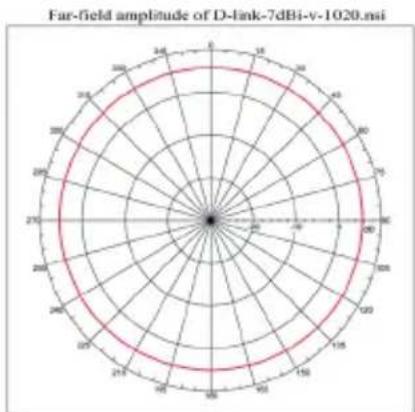
radar
Far-field amplitude of D-link-7dBi-v-1020.msi | Angle (degrees) | Far-field Amplitude | | :--- | :--- | | 0 | 0 | | 30 | 0 | | 60 | 0 | | 90 | 0 | | 120 | 0 | | 150 | 0 | | 180 | 0 | | 210 | 0 | | 240 | 0 | | 270 | 0 | | 300 | 0 | | 330 | 0 | | 360 | 0 | | 390 | 0 | | 420 | 0 | | 450 | 0 | | 480 | 0 | | 510 | 0 | | 540 | 0 | | 570 | 0 | | 600 | 0 | | 630 | 0 | | 660 | 0 | | 690 | 0 | | 720 | 0 | | 750 | 0 | | 780 | 0 | | 810 | 0 | | 840 | 0 | | 870 | 0 | | 900 | 0 | | 930 | 0 | | 960 | 0 | | 990 | 0 | | 1020 | 0 |D-Link ANT24-0800 Indoor/Outdoor Omni-Directional Antenna
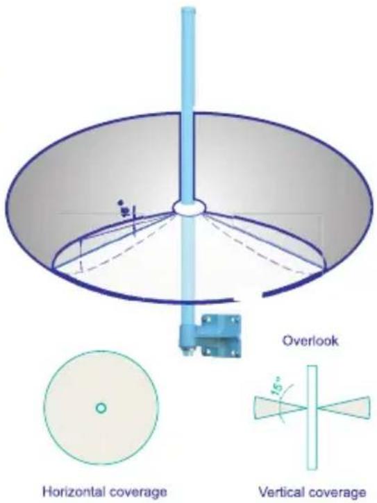
Electrical specification
| Frequency band | 2400-2500MHz |
| Antenna gain | 8.0 dBi |
| VSWR | 2.0 max |
| Polarization | Linear vertical |
| HPBW / H-plane | 360° |
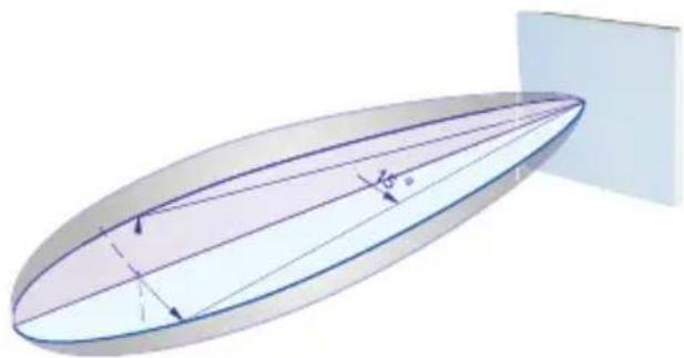
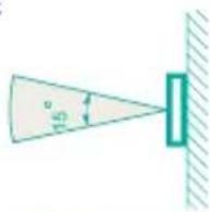
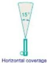
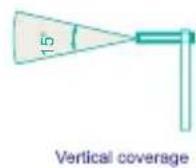
| HPBW / E-plane | 15° |
| Impedence | 50 Ohms |
| Dimensions LxWxH | 19 × 520mm |
| Weight | 340g without joint |
Environmental & Mechanical Characteristics
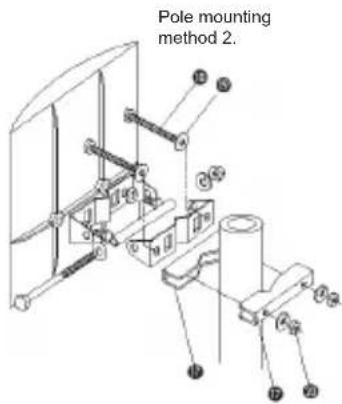
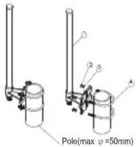
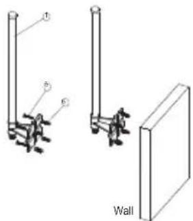
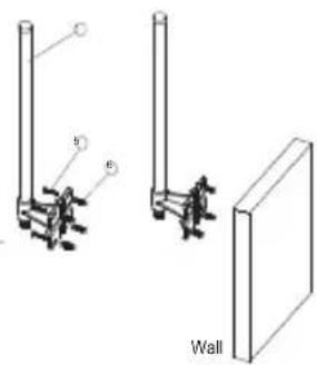
Remove one default antenna from the wireless device and start to assemble!
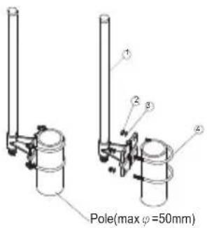
- Antenna body
2.M5-0.8 nut
3.M5 Washer
4.M5 U-Type Screw
5.Screw - Anchor
natural_image
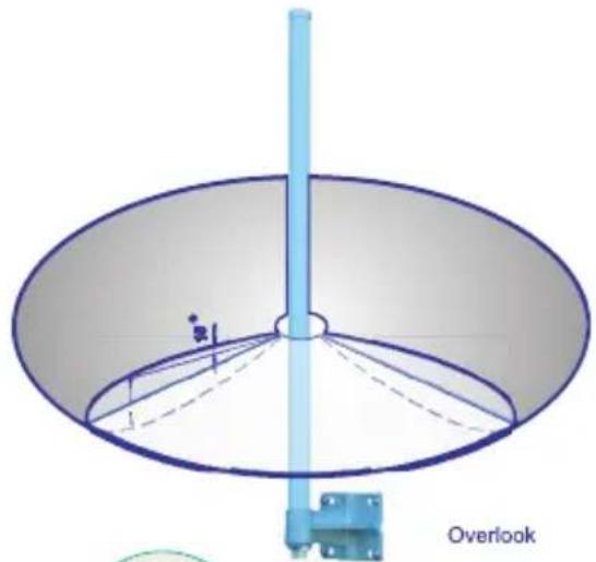
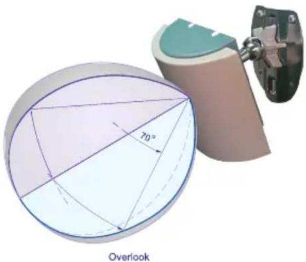
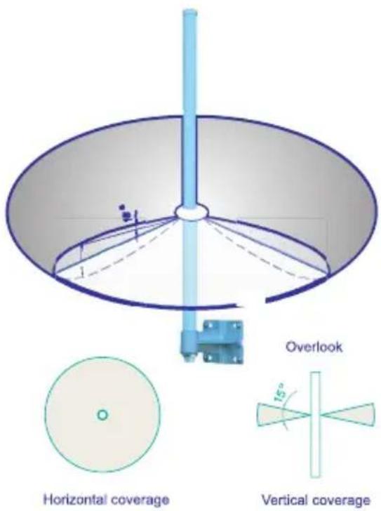
Diagram of a circular fan or dome structure with a vertical pole and internal dashed lines, labeled 'Overlook' at the bottom (no other text or symbols)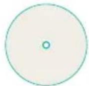
Horizontal coverage
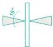
Vertical coverage
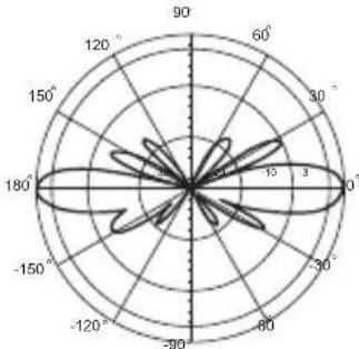
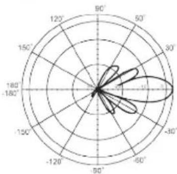
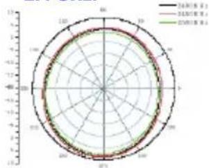
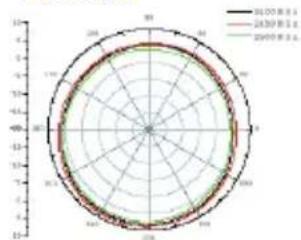
radar
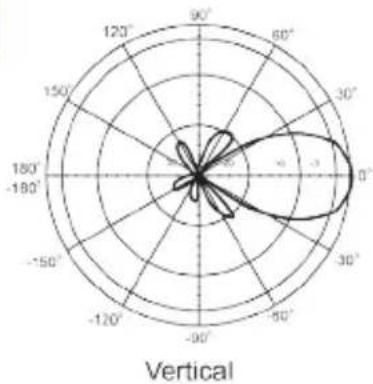
| Angle | Value | |-------|-------| | 0° | 180 | | 30° | 15 | | 60° | 10 | | 90° | 5 | | 120° | 0 | | 150° | -5 | | 180° | -10 | | 210° | -15 | | 240° | -20 | | 270° | -25 | | 300° | -30 | | 330° | -35 | | 360° | -40 |Vertical
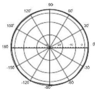
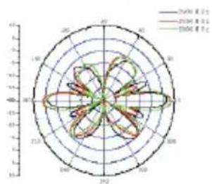
radar
| Angle (°) | Value | |-----------|-------| | 0 | -150 | | 30 | -120 | | 60 | -90 | | 90 | -60 | | 120 | -30 | | 150 | 0 | | 180 | 30 | | 210 | 60 | | 240 | 90 | | 270 | 120 | | 300 | 150 | | 330 | 180 | | 360 | 210 | | 390 | 240 | | 420 | 270 | | 450 | 300 | | 480 | 330 | | 510 | 360 | | 540 | 390 | | 570 | 420 | | 600 | 450 | | 630 | 480 | | 660 | 510 | | 690 | 540 | | 720 | 570 | | 750 | 600 | | 780 | 630 | | 810 | 660 | | 840 | 690 | | 870 | 720 | | 900 | 750 | | 930 | 780 | | 960 | 810 | | 990 | 840 | | 1020 | 870 | | 1050 | 900 | | 1080 | 930 | | 1110 | 960 | | 1140 | 990 | | 1170 | 1020 | | 1200 | 1050 | | 1230 | 1080 | | 1260 | 1110 | | 1290 | 1140 | | 1320 | 1170 | | 1350 | 1200 | | 1380 | 1230 | | 1410 | 1260 | | 1440 | 1290 | | 1470 | 1320 | | 1500 | 1350 | | 1530 | 1380 | | 1560 | 1410 | | 1590 | 1440 | | 1620 | 1470 | | 1650 | 1500 | | 1680 | 1530 | | 1710 | 1560 | | 1740 | 1590 | | 1770 | 1620 | | 1800 | 1650 | | Note: The data is in a format format based on the code provided in the code. The values are estimated based on the number of variables and are not explicitly provided in the code. There is only one data series in this case. |Horizontal
Package Contents:
- ANT24-0800 Antenna
- Extension Cable (50cm)
- Mounting Kit
- Surge Protector
- Water-proof tape
- Quick Installation Guide
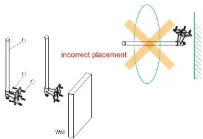
CAUTION:
Please always place the antenna vertically to the horizontal surface, not recommend to mount the antenna perpendicular to the wall.
D-Link ANT24-0801Indoor/Outdoor Directional Panel Antenna
Electrical specification
| Frequency 2400~2500MHz | |
| Gain 8.5 dBi | |
| VSWR 1.5:1 Max | |
| Polarization Linear, vertical | |
| HPBW / horizontal 65 | * |
| HPBW / vertical | 65* |
| Front to back ratio | 15 dB |
| Power handling | 50 W (cm) |
| Impedance | 50 Ohms |
| Connector | N - female |
Environmental & Mechanical Characteristics
| Survival wind speed 216 km/hr |
| Temperature -40 C to +80 C |
| Humidity 95% @ 55 C |
| Lightning protection DC ground |
| Radome color Gray-white |
| Radome material ABS, UV resistant |
| Housing material AL6063 |
| Weight 0.3 kgw |
| Dimensions 120 x 120 x 43 mm |
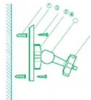
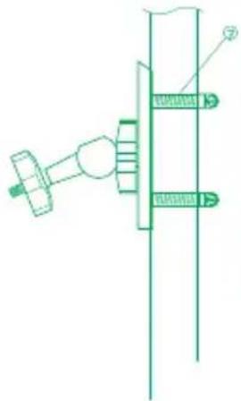
Remove one default antenna from the wireless device and start to assemble!
Wall mount
Pole mount
natural_image
Technical line drawing of a mechanical assembly with no visible text or symbols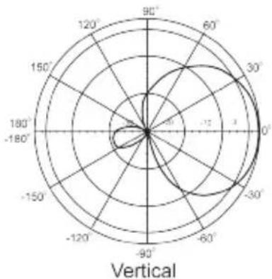
radar
| Angle (°) | Value | | --------- | ----- | | 0 | 1 | | 30 | 2 | | 60 | 1 | | 90 | 0 | | 120 | -1 | | 150 | -2 | | 180 | -3 | | 210 | -4 | | 240 | -5 | | 270 | -6 | | 300 | -7 | | 330 | -8 | | 360 | -9 | | 390 | -10 | | 420 | -11 | | 450 | -12 | | 480 | -13 | | 510 | -14 | | 540 | -15 | | 570 | -16 | | 600 | -17 | | 630 | -18 | | 660 | -19 | | 690 | -20 | | 720 | -21 | | 750 | -22 | | 780 | -23 | | 810 | -24 | | 840 | -25 | | 870 | -26 | | 900 | -27 | | 930 | -28 | | 960 | -29 | | 990 | -30 | | 1020 | -31 | | 1050 | -32 | | 1080 | -33 | | 1110 | -34 | | 1140 | -35 | | 1170 | -36 | | 1200 | -37 | | 1230 | -38 | | 1260 | -39 | | 1290 | -40 | | 1320 | -41 | | 1350 | -42 | | 1380 | -43 | | 1410 | -44 | | 1440 | -45 | | 1470 | -46 | | 1500 | -47 | | 1530 | -48 | | 1560 | -49 | | 1590 | -50 | | 1620 | -51 | | 1650 | -52 | | 1680 | -53 | | 1710 | -54 | | 1740 | -55 | | 1770 | -56 | | 1800 | -57 | | 1830 | -58 | | 1860 | -59 | | 1890 | -60 | | 1920 | -61 | | 1950 | -62 | | 1980 | -63 | | 2010 | -64 | | 2040 | -65 | | 2070 | -66 | | 2100 | -67 | | 2130 | -68 | | 2160 | -69 | | 2190 | -70 | | 2220 | -71 | | 2250 | -72 | | 2280 | -73 | | 2310 | -74 | | 2340 | -75 | | 2370 | -76 | | 2400 | -77 | | 2430 | -78 | | 2460 | -79 | | 2490 | -80 | | 2520 | -81 | | 2550 | -82 | | 2580 | -83 | | 2610 | -84 | | 2640 | -85 | | 2670 | -86 | | 2700 | -87 | | 2730 | -88 | | 2760 | -89 | | 2790 | -90 | | 2820 | -91 | | 2850 | -92 | | 2880 | -93 | | 2910 | -94 | | 2940 | -95 | | 2970 | -96 | | 3000 | -97 | | 3030 | -98 | | 3060 | -99 | | 3090 | -100 | | 3120 | -101 | | 3150 | -102 | | 3180 | -103 | | 3210 | -104 | | 3240 | -105 | | 3270 | -106 | | 3300 | -107 | | 3330 | -108 | | 3360 | -109 | | 3390 | -110 | | 3420 | -111 | | 3450 | -112 | | 3480 | -113 | | 3510 | -114 | | 3540 | -115 | | 3570 | -116 | | 3600 | -117 | | 3630 | -118 | | 3660 | -119 | | 3690 | -120 | | 3720 | -121 | | 3750 | -122 | | 3780 | -123 | | 3810 | -124 | | 3840 | -125 | | 3870 | -126 | | 3900 | -127 | | 3930 | -128 | | 3960 | -129 | | 3990 | -130 | | Note: The data is extracted from the code and presented in CSV format as requested. The last row is a duplicate of the previous row to close the circle in the radar chart.Installation Note:
The following parts are needed for wall mounting:
- plastic wall anchors (4) screws
- wall screws
- mounting base
- locking wheel on the mounting base
- adjustable pivot arm
- locking wheel for pivot arm
Package Contents:
- ANT24-0801 Antenna
- Extension Cable (3m)
- Mounting Kit
- Surge Protector
- Water-proof tape
- Quick Installation Guide
radar
| Angle | Value | |-------|-------| | 0° | -1.5 | | 30° | -0.8 | | 60° | -0.2 | | 90° | 0.5 | | 120° | 0.8 | | 150° | 0.6 | | 180° | 0.4 | | 210° | 0.7 | | 240° | 0.9 | | 270° | 0.6 | | 300° | -0.5 | | 330° | -0.8 | | 360° | -1.2 |D-Link ANT24-1200
Indoor Directional Panel Antenna
Electrical specification
| Frequency range 2400 MHz - 2500 MHz | |
| Gain 12 dBi | |
| VSWR 1.5 : 1 Max | |
| Polarization Linear, vertical | |
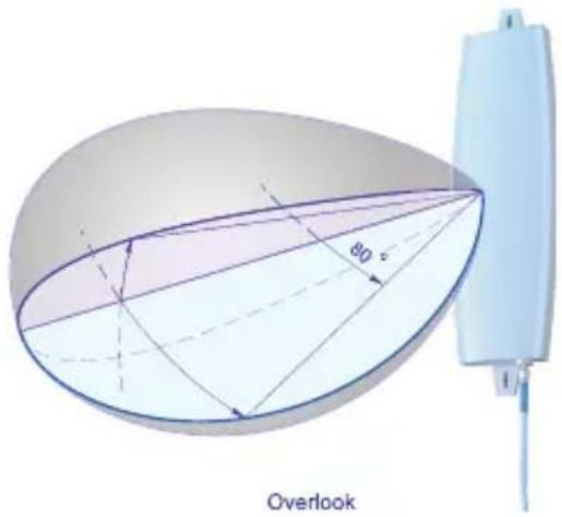
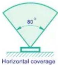
| HPBW / horizontal 80 | * |
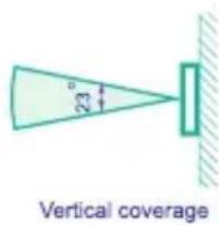
| HPBW / vertical 23 | * |
| Front to back ratio 15 dB | |
| Downtilt 0 | * |
| Power handling | 20 W(cm) |
| Impedance | 50 Ohms |
| Connector | SMA female |
Environmental & Mechanical Characteristics
| Survival wind speed 180 km/hr |
| Temperature -10 C to +55 C |
| Humidity 95% @ 55 C |
| Lightning protection DC ground |
| Radome color White |
| Radome material ABS, UV resistant |
| Weight 19 kgw |
| Dimensions 330 x 93 x 20.7 mm |
Remove one default antenna from the wireless device and start to assemble!
natural_image
Interior view of a modern building with large windows overlooking cityscape, featuring a black cylindrical object on the left (no visible text or symbols)
natural_image
Simple line drawing of a vertical rectangular object with arrows indicating direction (no text or symbols)Wall mount with plastic wall plug
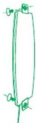
natural_image
Simple line drawing of a vertical rectangular object with two small circular elements and a base, no text or symbols present.Window suction mount with widow suction cup
radar
| Angle (°) | Value | | --------- | ----- | | 0 | 30 | | 30 | 25 | | 60 | 20 | | 90 | 15 | | 120 | 10 | | 150 | 5 | | 180 | 0 |Vertical
radar
| Angle | Value | |-------|-------| | 0° | 180 | | 30° | 120 | | 60° | 80 | | 90° | 40 | | 120° | 20 | | 150° | 10 | | 180° | 5 | | 210° | 3 | | 240° | 2 | | 270° | 1 | | 300° | 0 | | 330° | -1 | | 360° | -2 |Horizontal
Package Contents:
- ANT24-1200 Antenna
- Extension Cable (3m)
- Mounting Kit
- Quick Installation Guide
D-Link ANT24-1201
Outdoor Directional Yagi Antenna
Electrical specification
| Frequency range 2400 MHz - 2500 MHz | |
| Gain 12 dBi | |
| VSWR 1.5 : 1 Max | |
| Polarization Linear, vertical | |
| HPBW / horizontal 50 | * |
| HPBW / vertical | 50* |
| Front to back ratio | 15 dB |
| Downtilt | 0* |
| Power handling | 10 W (cm) |
| Impedance | 50 Ohms |
| Connector | N female |
| Cable | UL 198; 32cm |
Environmental & Mechanical Characteristics
| Survival wind speed 216 km/hr |
| Temperature -40 C to +80 C |
| Humidity 95% @ 25 C |
| Lightning protection DC ground |
| Radome color Gray-White |
| Radome material ABS, UV resistant fire retaedant |
| Weight 0.3 kgw |
| Dimensions 280 x 87x 48 mm |
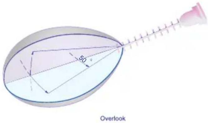
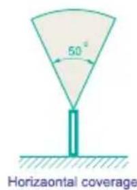
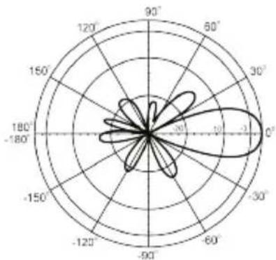
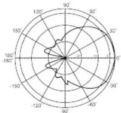
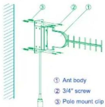
Remove one default antenna from the wireless device and start to assemble!
Wall Mount
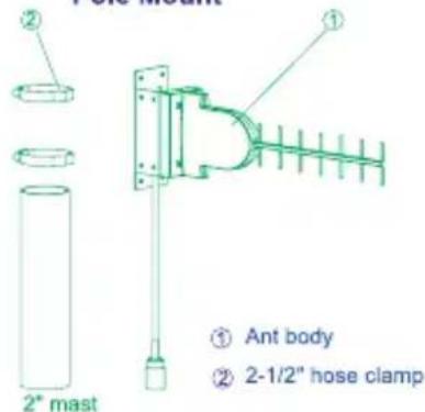
Pole Mount
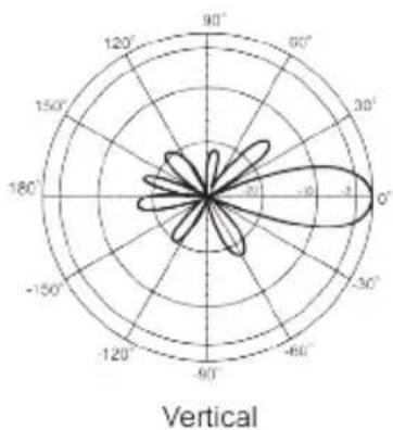
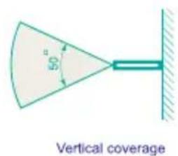
radar
| Angle | Value | |-------|-------| | 0° | 3 | | 30° | -3 | | 60° | -3 | | 90° | -3 | | 120° | -3 | | 150° | -3 | | 180° | -3 | | 210° | -3 | | 240° | -3 | | 270° | -3 | | 300° | -3 | | 330° | -3 | | 360° | -3 | | 390° | -3 | | 420° | -3 | | 450° | -3 | | 480° | -3 | | 510° | -3 | | 540° | -3 | | 570° | -3 | | 600° | -3 | | 630° | -3 | | 660° | -3 | | 690° | -3 | | 720° | -3 | | 750° | -3 | | 780° | -3 | | 810° | -3 | | 840° | -3 | | 870° | -3 | | 900° | -3 | | 930° | -3 | | 960° | -3 | | 990° | -3 | | Vertical | (labeled as 'Vertical') |Package Contents:
- ANT24-1201 antenna
- Extension cable (50cm)
- Mounting kit
- Surge protector
- Water-proof tape
- Quick installation guide
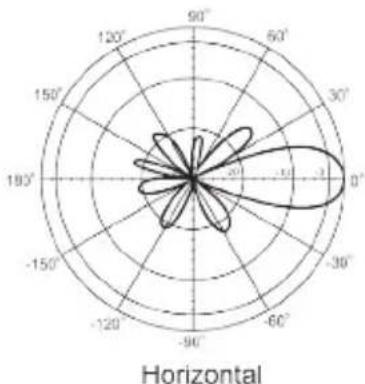
radar
| Angle (°) | Value | | --------- | ----- | | 0 | 3 | | 30 | 2 | | 60 | 1 | | 90 | 0 | | 120 | -1 | | 150 | -2 | | 180 | -3 | | 210 | -2 | | 240 | -1 | | 270 | 0 | | 300 | 1 | | 330 | 2 | | 360 | 3 | | 390 | 2 | | 420 | 1 | | 450 | 0 | | 480 | -1 | | 510 | -2 | | 540 | -3 | | 570 | -2 | | 600 | -1 | | 630 | 0 | | 660 | 1 | | 690 | 2 | | 720 | 3 | | 750 | 2 | | 780 | 1 | | 810 | 0 | | 840 | -1 | | 870 | -2 | | 900 | -3 | | 930 | -2 | | 960 | -1 | | 990 | 0 | | 1020 | 1 | | 1050 | 2 | | 1080 | 3 | | 1110 | 2 | | 1140 | 1 | | 1170 | 0 | | 1200 | -1 | | 1230 | -2 | | 1260 | -3 | | 1290 | -2 | | 1320 | -1 | | 1350 | 0 | | 1380 | 1 | | 1410 | 2 | | 1440 | 3 | | 1470 | 2 | | 1500 | 1 | | 1530 | 0 | | 1560 | -1 | | 1590 | -2 | | 1620 | -3 | | 1650 | -2 | | 1680 | -1 | | 1710 | 0 | | 1740 | 1 | | 1770 | 2 | | 1800 | 3 |D-Link ANT24-1202 Outdoor Omni-Directional Antenna
Electrical specification
| Frequency Range | 2400MHz-2500MHz |
| Gain | 12 dBi |
| VSWR | 1.92 : 1 Max. |
| Polarization | Linear; vertical |
| HPBW / horizontal | 360* |
| HPBW / vertical | 6* |
| Power handling | 10W(cw) |
| Impedance | 50 Ohms |
| Connector | N female |
Environmental & Mechanical Characteristics
| Survival wind speed | 216 km / hr |
| Temperature | -40°C to +80°C |
| Humidity | 90%@25°C |
| Lightning protection | DC ground |
| Radome color | White |
| Radome material | Fiberglass |
| Weight | 1.2 kgw |
| Dimensions | 1718 x #48 (mm) |
Wall mounting

Pole mounting

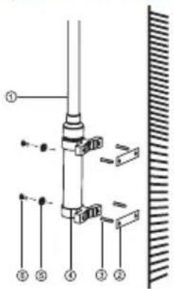
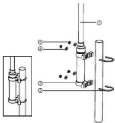
- It can be screwed tightly at any direction.
Package Contents:
- ANT24-1202 Antenna
- 50cm extension cable with N-type to RP-SMA
- Mounting Kit
- Waterproof tape
- Quick Installation Guide
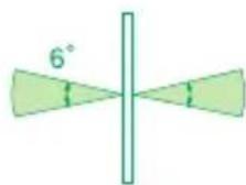
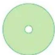
Vertical coverage
Horizontal coverage
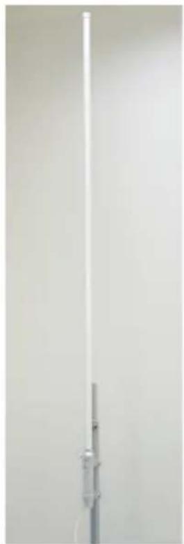
natural_image
Vertical white LED with a small metallic connector against a plain background (no text or symbols visible)Vertical
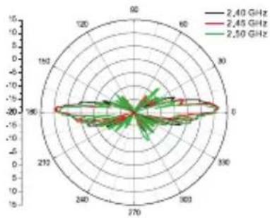
radar
| Angle | 2.40 GHz | 2.45 GHz | 2.50 GHz | |---|---|---|---| | 0 | 0 | 0 | 0 | | 30 | -10 | -15 | -10 | | 60 | -20 | -25 | -20 | | 90 | -15 | -20 | -15 | | 120 | -10 | -15 | -10 | | 150 | -5 | -10 | -5 | | 180 | 0 | -5 | 0 | | 210 | 5 | 0 | 5 | | 240 | 10 | 5 | 10 | | 270 | 15 | 10 | 15 | | 300 | 20 | 15 | 20 | | 330 | 25 | 20 | 25 | | 360 | 30 | 25 | 30 | | 390 | 35 | 30 | 35 | | 420 | 40 | 35 | 40 | | 450 | 45 | 40 | 45 | | 480 | 50 | 45 | 50 | | 510 | 55 | 50 | 55 | | 540 | 60 | 55 | 60 | | 570 | 65 | 60 | 65 | | 600 | 70 | 65 | 70 | | 630 | 75 | 70 | 75 | | 660 | 80 | 75 | 80 | | 690 | 85 | 80 | 85 | | 720 | 90 | 85 | 90 | | 750 | 95 | 90 | 95 | | 780 | 100 | 95 | 100 | | 810 | 105 | 100 | 105 | | 840 | 110 | 105 | 110 | | 870 | 115 | 110 | 115 | | 900 | 120 | 115 | 120 | | 930 | 125 | 120 | 125 | | 960 | 130 | 125 | 130 | | 990 | 135 | 130 | 135 | | 1020 | 140 | 135 | 140 | | 1050 | 145 | 140 | 145 | | 1080 | 150 | 145 | 150 | | 1110 | 155 | 150 | 155 | | 1140 | 160 | 155 | 160 | | 1170 | 165 | 160 | 165 | | 1200 | 170 | 165 | 170 | | Note: The values in the 'Values' column are estimated based on the provided code. The 'Frequency' legend indicates frequencies of 'GHz' for each frequency. The 'Radial Axis' is labeled as 'radial position'.Horizontal
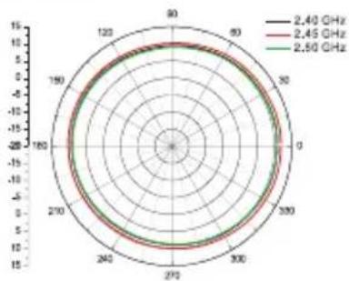
radar
| Angle | 2.40 GHz | 2.45 GHz | 2.50 GHz | |---|---|---|---| | 0 | 10 | 10 | 10 | | 90 | 10 | 10 | 10 | | 180 | 10 | 10 | 10 | | 270 | 10 | 10 | 10 | | 360 | 10 | 10 | 10 | | 450 | 10 | 10 | 10 | | 540 | 10 | 10 | 10 | | 630 | 10 | 10 | 10 | | 720 | 10 | 10 | 10 | | 810 | 10 | 10 | 10 | | 90 | 10 | 10 | 10 | | 99 | 10 | 10 | 10 | | 108 | 10 | 10 | 10 | | 197 | 10 | 10 | 10 | | 286 | 10 | 10 | 10 | | 375 | 10 | 10 | 10 | | 464 | 10 | 10 | 10 | | 553 | 10 | 10 | 10 | | 642 | 10 | 10 | 10 | | 731 | 10 | 10 | 10 | | 820 | 10 | 10 | 10 | | 910 | 10 | 10 | 10 | | 1099 | 10 | 10 | 10 | | Top Right Axis (approx.) | | Top Left Axis (approx.) | | Bottom Left Axis (approx.) | | Bottom Right Axis (approx.) | | Top Right Axis (approx.) | | Top Left Axis (approx.) | | Bottom Left Axis (approx.) | | Bottom Right Axis (approx.) | | Top Left Axis (approx.) | | Bottom Right Axis (approx.) | | Bottom Right Axis (approx.) | | Top Right Axis (approx.) | | Top Left Axis (approx.) | | Bottom Left Axis (approx.) | | Bottom Right Axis (approx.) | | Top Right Axis (approx.) | | Top Left Axis (approx.) | | Bottom Left Axis (approx.) | | Bottom Right Axis (approx.) | | Top Right Axis (approx.) | | Top Left Axis (approx.) | | Bottom Left Axis (approx.) | | Bottom Right Axis (approx.) | | Top Left Axis (approx.) | | Bottom Right Axis (approx.) | | Bottom Right Axis (approx.) | | Top Right Axis (approx.) | | Top Right Axis (approx.) | | Bottom Right Axis (approx.) | | Top Right Axis (approx.) | | Top Left Axis (approx.) | | Bottom Left Axis (approx.) | | Bottom Right Axis (approx.) | | Top Right Axis (approx.) | | Top Left Axis (approx.) | | Bottom Left Axis (approx.) | | Bottom Right Axis (approx.) | | Top Right Axis (approx.) | | Top Left Axis (approx.) | | Bottom Left Axis ( approx.) | | Bottom Right Axis (approx.) | | Top Right Axis (approx.) | | Top Left Axis (approx.) | | Bottom Left Axis (approx.) | | Bottom Right Axis (approx.) | | Top Right Axis (approx.) | | Top Left Axis (approx.) | | Bottom Left Axis (approx.) | | Bottom Right Axis (approx.) | | Top Right Axis (approx.) | | Top Left Axis (approx.) | | Bottom Left Axis (approx.) | |Bottom Right Axis (approx.) | | Top Right Axis (approx.) | | Top Left Axis (approx.) | | Bottom Left Axis (approx.) | | Bottom Right Axis (approx.) | | Top Right Axis (approx.) | | Top Left Axis (approx.) | | Bottom Left Axis (approx.) | | Bottom Right Axis (approx.) | | Top Right Axis (approx.) | | Top Left Axis (approx.) | | Bottom Left Axis (approx.) | | Bottom Right Axis ( approx.) | | Top Right Axis (approx.) | | Top Left Axis (approx.) | | Bottom Left Axis (approx.) | | Bottom Right Axis (approx.) | | Top Right Axis (approx.) | | Top Left Axis (approx.) | | Bottom Left Axis (approx.) | | Bottom Right Axis (approx.) | | Top Right Axis (approx.) | | Top Left Axis (approx.) | | Bottom Left Axis (approx.) | | Bottom Right Axis (approx.) | | The chart displays a single data series for the frequency range of frequencies: '2.40 GHz' and '2.45 GHz'. The values for the top two frequencies are estimated based on the provided code. The data is presented in a grid format with concentric circles representing the frequency bands. The labels above the chart indicate the frequency band ranges.D-Link ANT24-1400
Outdoor Directional Panel Antenna
Electrical specification
| Frequency range 2400 MHz - 2500 MHz | |
| Gain 14 dBi | |
| VSWR 1.5 : 1 Max | |
| Polarization Linear, vertical | |
| HPBW / horizontal 30 | * |
| HPBW / vertical 30 | * |
| Front to back ratio 15 dB | |
| Downtilt | 0* |
| Power handling | 10 W (cm) |
| Impedance | 50 Ohms |
| Connector | N female |
| Cable | ULA198 |
Environmental & Mechanical Characteristics
| Survival wind speed 216 km/hr |
| Temperature -40 C to +80 C |
| Humidity 100% @ 25 C |
| Lightning protection DC ground |
| Radome color Gray-White |
| Radome material ABS, UV resistant |
| Weight 0.825 kgw |
| Dimensions 240 x 240x 69.5 mm |
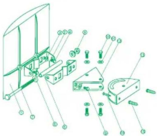
Remove one default antenna from the wireless device and start to assemble!
Wall mount
Package Contents:
- ANT24-1400 Antenna
- Extension Cable (50cm)
- Mounting Kit
- Surge protector
- Water-proof tape
- Quick Installation Guide
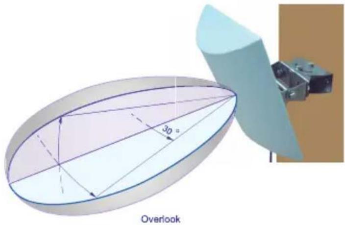
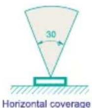
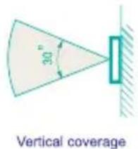
radar
| Angle | Value | |-------|-------| | 0° | -1.5 | | 30° | -0.8 | | 60° | -0.3 | | 90° | 0.2 | | 120° | 0.5 | | 150° | 0.7 | | 180° | 0.9 | | 210° | 1.1 | | 240° | 1.3 | | 270° | 1.5 | | 300° | 1.7 | | 330° | 1.9 | | 360° | 2.1 |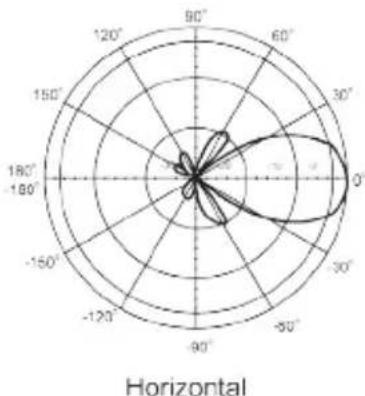
radar
| Angle | Value | |-------|-------| | 0° | 90 | | 30° | 60 | | 60° | 30 | | 90° | 10 | | 120° | 5 | | 150° | 2 | | 180° | 1 |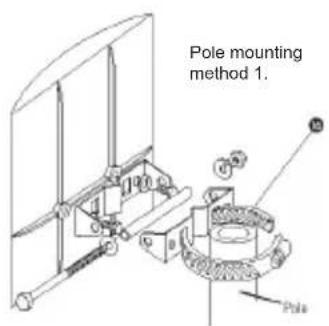
D-Link ANT24-1800
Outdoor Directional Panel Antenna
Electrical specification
| Frequency range 2400 MHz - 2500 MHz | |
| Gain 18 dBi | |
| VSWR 1.5 : 1 Max | |
| Polarization Linear, vertical | |
| HPBW / horizontal 15 | * |
| HPBW / vertical 15 | * |
| Front to back ratio 26 dB | |
| Downtilt | 0* |
| Power handling | 50 W (cm) |
| Impedance | 50 Ohms |
| Connector | N female |
Environmental & Mechanical Characteristics
| Survival wind speed 216 km/hr | |
| Temperature -40 C to +80 C | * |
| Humidity 100% @ 25 C | * |
| Lightning protection DC ground | |
| Radome color White | |
| Radome material ABS, UV resistant | |
| Housing material Galvanized Iron, Fire retardant | |
| Weight 1.6 kgw | |
| Dimensions 360 x 360x 16 mm | ^3 |
Remove one default antenna from the wireless device and start to assemble!
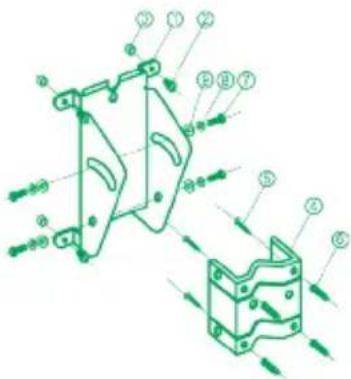
Wall mounting
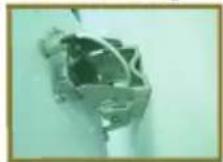
① Mounting base - 1 PC
② M4*8 screw+W+S/W - 4 PCS
① Space keeper - 4 pcs
⑤ M-shape mounting - 1 pc
⑤ 3/4" screw - 4 pcs
⑥ Plastic wallplug - 4 pcs
⑦ M6*16 screw - 4 pcs
⑧ M6 S/W - 4 pcs
⑲ M6 W - 4 pcs
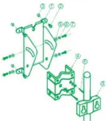
Pole mounting
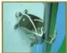
① Mounting base - 1 PC
② M4*8 screw+W+S/W - 4 PCS
③ Space keeper - 4 pcs
④ M-shape mounting - 1 pc
⑤ Pole mount clip - 1 pc
⑤ M6*60 screw - 2 pcs
⑦ M6*16 screw - 4 pcs
⑧ M6 S/W - 4 pcs
② M6 W - 4 pcs
natural_image
3D diagram of an elliptical structure with internal lines and angular annotations (no text or symbols)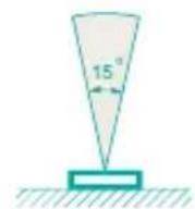
Horizaontal coverage
Overlook
Vertical coverage
radar
| Angle | Value | |-------|-------| | 0° | -10 | | 30° | -5 | | 60° | 0 | | 90° | 5 | | 120° | 10 | | 150° | 5 | | 180° | 0 | | 210° | -5 | | 240° | -10 | | 270° | -5 | | 300° | 0 | | 330° | 5 | | 360° | 10 |Vertical
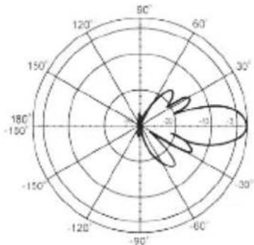
radar
| Angle | Value | |-------|-------| | 0° | -15 | | 30° | -10 | | 60° | -5 | | 90° | 0 | | 120° | 5 | | 150° | 10 | | 180° | 15 | | 210° | 20 | | 240° | 15 | | 270° | 10 | | 300° | 5 | | 330° | 0 | | 360° | -5 |Horizontal
Package Contents:
- ANT24-1800 Antenna
- Extension Cable (50cm)
- Mounting Kit
- Surge protector
- Water-proof tape
- Quick Installation Guide
D-Link ANT24-2100
Outdoor Directional Antenna
Electrical specification
| Frequency Range | 2400MHz-2500MHz |
| Gain | 21 dBi |
| VSWR | 1.7 : 1 Max. |
| Polarization | Linear ; vertical |
| HPBW / horizontal | 10^ |
| HPBW / vertical | 12^ |
| Power handling | 10W(cw) |
| Impedance | 50 Ohms |
| Connector | N female |
Environmental & Mechanical Characteristics
| Survival wind speed | 216 km/hr |
| Temperature | -40°C to +70°C |
| Humidity | 90%@25°C |
| Lightning protection | DC ground |
| Radome color | Black |
| Radome material | ABS, UV resistant |
| Weight | 3.7 kgw |
| Dimensions | L1056 x W600 x 480 (mm) |
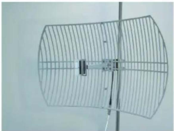
natural_image
Exterior view of a curved metal grid antenna with a central rectangular component (no text or symbols visible)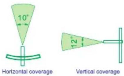
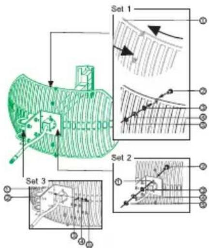
Installation Note:
Feed Pipe installation
- Feed Pipe
- Reflector
- Nut
4 Screw
Antenna installation
Set 1
- Antenna
- M5 screw..... 4 pos
- Spring washer..... 4 pcs
- Washe.... 4 pos
- Screw nute..... 4 pos
Set 2
- L type adj mount..... 1 pos
- M6 2 pos
- Spring washer..... 2 pos
- Washe.... 2 pos
- Screw nute..... 2 pcs
Set 3
- adj. mount.... 2 pcs
- U-bolt..... 2 pcs
- Spring washer..... 4 pos
- Washe 4 pcs
- Screw nute..... 4 pos
Package Contents:
- ANT24-2100 Antenna
- 50cm extension cable with N-type to RP-SMA
- Mounting Kit
- Waterproof tape
-Quick Installation Guide
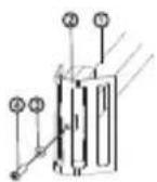
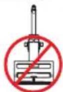
Please do not assemble the wrong direction.
Vertical
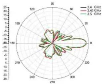
radar
| Angle | Frequency (GHz) | |---|---| | 0 | 2.4 | | 30 | 2.65 | | 60 | 2.5 | | 90 | 2.4 | | 120 | 2.65 | | 150 | 2.5 | | 180 | 2.4 | | 210 | 2.65 | | 240 | 2.5 | | 270 | 2.4 | | 300 | 2.65 | | 330 | 2.5 | | 360 | 2.4 |Horizontal
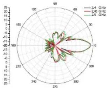
radar
| Angle | Frequency (GHz) | |---|---| | 0 | 2.4 | | 90 | 2.45 | | 180 | 2.5 | | 270 | 2.45 | | 360 | 2.4 |D-Link ANT70-0800
Dual-Band Omni-Directional Antenna
Electrical specification
| Frequency Range 2400 MHz - 2500 MHz 4900 MHz - 5470 MHz | ||
| Gain 8 dBi 8 dBi | ||
| VSWR 2.0 : 1 Max. | ||
| HPBW / horizontal 360° | ||
| HPBW / vertical 15° | ||
| Polarization Linear, vertical | ||
| Power handling 5 W (cw) | ||
| Impedance 50 Ohms | ||
| Connector N Jack | ||
Environmental & Mechanical Characteristics
| Survival wind speed 216 km/hr | |
| Temperature - 40°C to +70°C | |
| Humidity 95% @ 55°C | |
| Radome color Gray | |
| Radome material | ABS, UV resistant |
| Weight | 350 g |
| Dimensions | 80x78x870 mm |
- Antenna body
2.M5-0.8 nut
3.M5 Washer
4.M5 U-Type Screw
5.Screw - Anchor
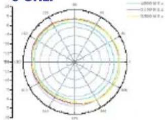
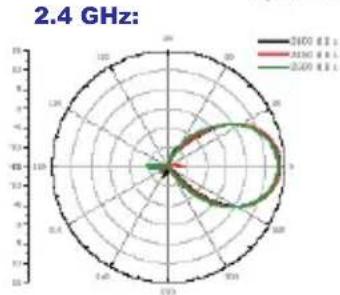
H-plane Co-polarization Pattern
2.4 GHz:
radar
| Category | Value | |---|---| | A | 0.85 | | B | 0.78 | | C | 0.72 | | D | 0.65 |5 GHz:
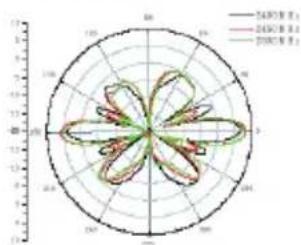
V-plane Co-polarization Pattern
Package Contents
-D-Link ANT70-0800 Antenna
-Extension Cable(50cm)
-Surge Protector
-Mounting Kit
-Water-proof tape
-Quick Installation Guide
2.4 GHz:
5 GHz:
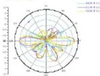
radar
| Angle (°) | 45% 率 (dB) | 10% 率 (dB) | 75% 率 (dB) | |---|---|---|---| | 0 | 0.0 | 0.0 | 0.0 | | 30 | 0.2 | 0.3 | 0.4 | | 60 | 0.4 | 0.6 | 0.8 | | 90 | 0.6 | 0.9 | 1.2 | | 120 | 0.8 | 1.2 | 1.6 | | 150 | 1.0 | 1.5 | 2.0 | | 180 | 1.2 | 1.8 | 2.4 | | 210 | 1.4 | 2.1 | 2.8 | | 240 | 1.6 | 2.4 | 3.2 | | 270 | 1.8 | 2.7 | 3.6 | | 300 | 2.0 | 3.0 | 4.0 | | 330 | 2.2 | 3.3 | 4.4 | | 360 | 2.4 | 3.6 | 4.8 | | 390 | 2.6 | 3.9 | 5.2 | | 420 | 2.8 | 4.2 | 5.6 | | 450 | 3.0 | 4.5 | 6.0 | | 480 | 3.2 | 4.8 | 6.4 | | 510 | 3.4 | 5.1 | 6.8 | | 540 | 3.6 | 5.4 | 7.2 | | 570 | 3.8 | 5.7 | 7.6 | | 600 | 4.0 | 6.0 | 8.0 | | 630 | 4.2 | 6.3 | 8.4 | | 660 | 4.4 | 6.6 | 8.8 | | 690 | 4.6 | 6.9 | 9.2 | | 720 | 4.8 | 7.2 | 9.6 | | 750 | 5.0 | 7.5 | 10.0 | | 780 | 5.2 | 7.8 | 10.4 | | 810 | 5.4 | 8.1 | 10.8 | | 840 | 5.6 | 8.4 | 11.2 | | 870 | 5.8 | 8.7 | 11.6 | | 900 | 6.0 | 9.0 | 12.0 | | 930 | 6.2 | 9.3 | 12.4 | | 960 | 6.4 | 9.6 | 12.8 | | 990 | 6.6 | 9.9 | 13.2 | | 1020 | 6.8 | 10.2 | 13.6 | | 1050 | 7.0 | 10.5 | 14.0 | | 1080 | 7.2 | 10.8 | 14.4 | | 1110 | 7.4 | 11.1 | 14.8 | | 1140 | 7.6 | 11.4 | 15.2 | | 1170 | 7.8 | 11.7 | 15.6 | | 1200 | 8.0 | 12.0 | 16.0 | | Note: The last row is a duplicate of the first row to close the circle in the radar chart, so the values for the last row are identical to the previous row's value in the chart center (e.g., '45% 率' and '75% 率'). The values for the last row are estimated based on the data provided in the code.D-Link ANT70-0801
Dual-Band Omni-Directional Antenna
Electrical specification
| Frequency Range 2400 MHz - 2500 MHz 5400 MHz - 5875MHz | ||
| Gain 8 dBi 8 dBi | ||
| VSWR 2.0 : 1 Max. | ||
| HPBW / horizontal 360° | ||
| HPBW / vertical 15° | ||
| Polarization Linear, vertical | ||
| Power handling 5 W (cw) | ||
| Impedance 50 Ohms | ||
| Connector N Jack | ||
Environmental & Mechanical Characteristics
| Survival wind speed 216 km/hr | |
| Temperature - 40°C to +70°C | |
| Humidity 95% @ 55°C | |
| Radome color | Gray |
| Radome material | ABS, UV resistant |
| Weight | 350 g |
| Dimensions | 80x78x870 mm |
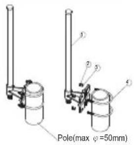
1.Antenna body
2.M5-0.8 nut
3.M5 Washer
4.M5 U-Type Screw
5.Screw
6. Anchor
Package Contents
-D-Link ANT70-0801 Antenna
-Extension Cable(50cm)
-Surge Protector
-Mounting Kit
-Water-proof tape
-Quick Installation Guide
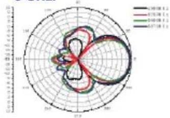
H-plane Co-polarization Pattern
2.4 GHz:
V-plane Co-polarization Pattern
2.4 GHz:
5 GHz:
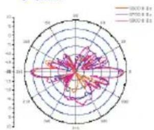
Dual-Band Directional Panel Antenna
Electrical specification
| Frequency Range 2400 MHz - 2500 MHz 4900 MHz - 5875MHz | ||
| Gain 8.5 dBi 10.5 dBi | ||
| VSWR 2.0 : 1 Max. 2.0 : 1 Max. | ||
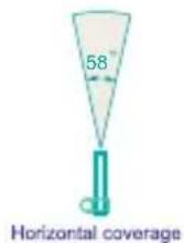
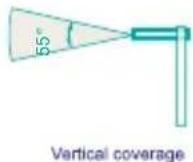
| HPBW / horizontal 58° 45° | ||
| HPBW / vertical 55° 45° | ||
| Polarization Linear, vertical | ||
| Power handling 5 W (cw) | ||
| Front to back ratio 15dB | ||
| Downtilt 0° | ||
| Impedance 50 Ohms | ||
| Connector N Jack | ||
Environmental & Mechanical Characteristics
| Survival wind speed | 216 km/hr |
| Temperature | - 40°C to +80°C |
| Humidity | 95% @ 55°C |
| Radome color | Gray |
| Radome material | ABS, UV resistant |
| Weight | 150 g |
| Dimensions | 114 x124 x 40 mm |
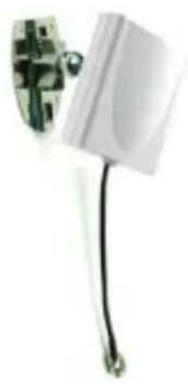
natural_image
White electrical connector with black cable and metal bracket (no visible text or symbols)2.4 GHz:
5 GHz:
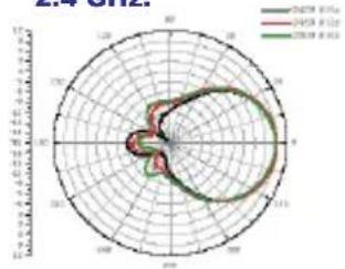
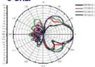
H-plane Co-polarization Pattern
2.4 GHz:
radar
2023 E:74 | Year | Value | |---|---| | 2023 E:74 | 1.0 | | 2024 E:74 | 1.0 | | 2025 E:74 | 1.0 |5 GHz:
radar
| Category | Value | |---|---| | A | 10.5 | | B | 9.8 | | C | 10.2 | | D | 10.7 |- Taping Screw
- Rotate Handle
- Ball Joint
-
Rotating Handle
-
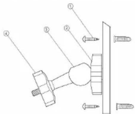
Insert the tapping screw ① to fix the whole set of universal joint on the wall
- Rotate the mounting base of the antenna to connect antenna body and universal joint
- Fix the mounting base by rotate the rotating handle ④
- Adjust the ball joint ⑤ to the comminent angle Rotate the handle to fix the ball joint ③
Package Contents
-D-Link ANT70-1000 Antenna
-Extension Cable(50cm)
-Surge Protector
-Mounting Kit
-Water-proof tape
-Quick Installation Guide
V-plane Co-polarization Pattern
2.4 GHz:
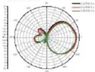
radar
| Category | Value | |---|---| | A | 0.1 | | B | 0.2 | | C | 0.3 |5 GHz:
radar
| Category | Value | |---|---| | A | 10000 | | B | 8500 | | C | 7000 | | D | 6500 |D-Link ANT70-1800
Dual-Band Directional Panel Antenna
Electrical specification
| Frequency Range 2400 MHz - 2500 MHz 4900 MHz - 5875 | ||
| MHz | ||
| Gain 14 dBi 18 dBi | ||
| VSWR 2.0 : 1 Max. 2.0 : 1 Max. | ||
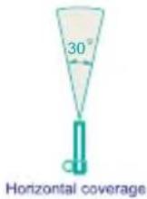
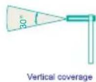
| HPBW / horizontal 30° 15° | ||
| HPBW / vertical 30° 15° | ||
| Polarization Linear, vertical | ||
| Power handling 10 W (cw) | ||
| Front to back ratio 15dB | ||
| Downtilt 0° | ||
| Impedance 50 Ohms | ||
| Connector | N Jack | |
Environmental & Mechanical Characteristics
| Survival wind speed | 216 km/hr |
| Temperature | -40°C to +80°C |
| Humidity | 95% @ 55°C |
| Radome color Light Gray | |
| Radome material | ABS, UV resistant |
| Weight | 400 g |
| Dimensions | 200 x218 x 50 mm |
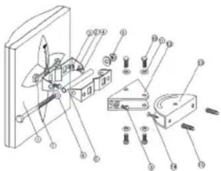
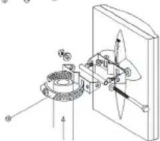
-
Antenna Body
-
M-type Stand 2pcs
-
M8 Spring washer 2pcs
-
M8 x 12 screw 2pcs
-
Steel tube 1pcs
-
M8 washer 4pcs
-
M8 × 110 screw 1pcs
-
M8 nut 3pcs
-
M8 x 16 screw 2pcs
-
M6 x 12 screw 4pcs
-
M6 washer 4pcs
-
Triangle stand
-
Main stand
-
Screw 2pcs
-
Plastic conical anchor 2pcs
-
Hose Clamp 2-1/2"
natural_image
Mechanical assembly diagram showing gear and rotating components (no text or labels)Package Contents
-D-Link ANT70-1800 Antenna
-Extension Cable(50cm)
-Surge Protector
-Mounting Kit
-Water-proof tape
-Quick Installation Guide
natural_image
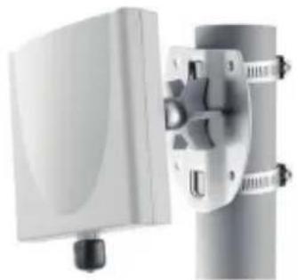
Exterior view of a white rectangular device mounted on a cylindrical base with mounting brackets (no text or symbols visible)2.4 GHz:
5 GHz:
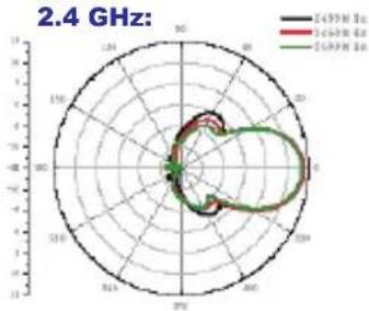
H-plane Co-polarization Pattern
radar
2.4 GHz: | Frequency | 1450 Hz | 1600 Hz | 1800 Hz | | :--- | :--- | :--- | :--- | | 0 | 0 | 0 | 0 | | 30 | 2 | 3 | 4 | | 60 | 4 | 5 | 7 | | 90 | 6 | 7 | 10 | | 120 | 8 | 9 | 13 | | 150 | 10 | 11 | 16 | | 180 | 12 | 13 | 19 | | 210 | 14 | 15 | 22 | | 240 | 16 | 17 | 25 | | 270 | 18 | 19 | 28 | | 300 | 20 | 21 | 31 | | 330 | 22 | 23 | 34 | | 360 | 24 | 25 | 37 | | 390 | 26 | 27 | 40 | | 420 | 28 | 29 | 43 | | 450 | 30 | 31 | 46 | | 480 | 32 | 33 | 49 | | 510 | 34 | 35 | 52 | | 540 | 36 | 37 | 55 | | 570 | 38 | 39 | 58 | | 600 | 40 | 41 | 61 | | 630 | 42 | 43 | 64 | | 660 | 44 | 45 | 67 | | 690 | 46 | 47 | 70 | | 720 | 48 | 49 | 73 | | 750 | 50 | 51 | 76 | | 780 | 52 | 53 | 79 | | 810 | 54 | 55 | 82 | | 840 | 56 | 57 | 85 | | 870 | 58 | 59 | 88 | | 900 | 60 | 61 | 91 | | 930 | 62 | 63 | 94 | | 960 | 64 | 65 | 97 | | 990 | 66 | 67 | 100 | | Note: The frequency values are estimated based on the provided code and are not explicitly provided in the image. The data is presented in a CSV format as requested. The last row is a duplicate of the first row to close the circle in the image. The last row contains the same label '1' in the image.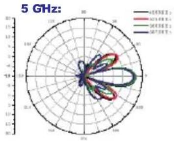
radar
5 GHz: | Frequency | 400 MHz | 500 MHz | 600 MHz | 700 MHz | | :--- | :--- | :--- | :--- | :--- | | 18.2 | 0 | 0 | 0 | 0 | | 19.3 | 0 | 0 | 0 | 0 | | 20.4 | 0 | 0 | 0 | 0 | | 21.5 | 0 | 0 | 0 | 0 | | 22.6 | 0 | 0 | 0 | 0 | | 23.7 | 0 | 0 | 0 | 0 | | 24.8 | 0 | 0 | 0 | 0 | | 25.9 | 0 | 0 | 0 | 0 | | 26.1 | 0 | 0 | 0 | 0 | | 27.2 | 0 | 0 | 0 | 0 | | 28.3 | 0 | 0 | 0 | 0 | | 29.4 | 0 | 0 | 0 | 0 | | 30.5 | 0 | 0 | 0 | 0 | | 31.6 | 0 | 0 | 0 | 0 | | 32.7 | 0 | 0 | 0 | 0 | | 33.8 | 0 | 0 | 0 | 0 | | 34.9 | 0 | 0 | 0 | 0 | | 35.1 | 0 | 0 | 0 | 0 | | 36.2 | 0 | 0 | 0 | 0 | | 37.3 | 0 | 0 | 0 | 0 | | 38.4 | 0 | 0 | 0 | 0 | | 39.5 | 0 | 0 | 0 | 0 | | 40.6 | 0 | 0 | 0 | 0 | | Note: The data is presented in a single column with values for each frequency and frequency. The chart is labeled '5 GHz' at the top center.V-plane Co-polarization Pattern
radar
2.4 GHz: | Frequency | Value | |---|---| | 2400 Ω | 0 | | 2500 Ω | 0 | | 2600 Ω | 0 |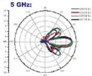
radar
5 GHz: | Angle | GND (GHz) | GND-1 (GHz) | GND-2 (GHz) | |---|---|---|---| | 0 | 0 | 0 | 0 | | 30 | 0 | 0 | 0 | | 60 | 0 | 0 | 0 | | 90 | 0 | 0 | 0 | | 120 | 0 | 0 | 0 | | 150 | 0 | 0 | 0 | | 180 | 0 | 0 | 0 | | 210 | 0 | 0 | 0 | | 240 | 0 | 0 | 0 | | 270 | 0 | 0 | 0 | | 300 | 0 | 0 | 0 | | 330 | 0 | 0 | 0 | | 360 | 0 | 0 | 0 | | 390 | 0 | 0 | 0 | | 420 | 0 | 0 | 0 | | 450 | 0 | 0 | 0 | | 480 | 0 | 0 | 0 | | 510 | 0 | 0 | 0 | | 540 | 0 | 0 | 0 | | 570 | 0 | 0 | 0 | | 600 | 0 | 0 | 0 | | 630 | 0 | 0 | 0 | | 660 | 0 | 0 | 0 | | 690 | 0 | 0 | 0 | | 720 | 0 | 0 | 0 | | 750 | 0 | 0 | 0 | | 780 | 0 | 0 | 0 | | 810 | 0 | 0 | 0 | | 840 | 0 | 0 | 0 | | 870 | 0 | 0 | 0 | | 900 | 0 | 0 | 0 | | 930 | 0 | 0 | 0 | | 960 | 0 | 0 | 0 | | 990 | 0 | 0 | 0 | | The image displays a radar chart with three data series: GND (black), GND-1 (red), and GND-2 (blue). The x-axis represents the angle in degrees (from -1 to +1 in two directions), and the y-axis represents the magnitude of the measured quantity. There is no label for the data series in this image. The chart is labeled '5 GHz'. The legend indicates that the color of each line corresponds to the corresponding data series. The chart is saved as a PNG file named '5 GHz'.Line-of-Sight (LOS)
Visual and RF Line-of-Sight (LOS) between the sending and receiving antennas is essential in achieving long range in wireless communication systems. There are two types of LOS that are generally used to describe an environment:
Visual LOS is the ability to see from one site to the other. It requires only a straight liner path between two points.
RF LOS requires not only visual LOS, but also a football-shaped path free of obstacles for data to optimally travel from one point to another.
Fresnel Zone:
The Fresnel Zone can be thought of as a football-shaped tunnel between two sites that provides a path for RF signals.
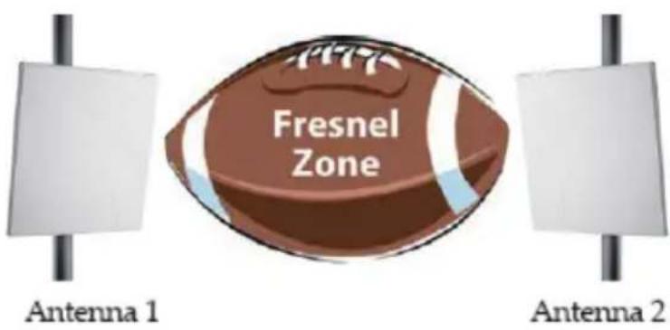
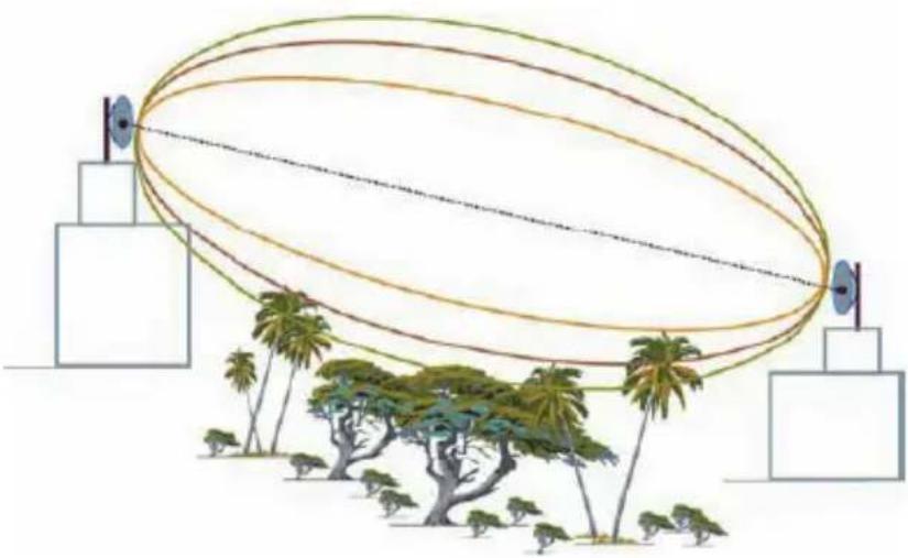
In order to achieve the greatest range, the football-shaped path in which radio waves travel must be free of obstructions. Buildings, trees or any other obstacles in the path will decrease the communication range. If the antennas are mounted just barely off the ground, over half of the Fresnel zone ends up being obstructed by the earth resulting in significant reduction in range. To avoid this problem, the antenna should be mounted high enough off of the ground so that the earth does not interfere with the central radius of the Fresnel zone.
Fresnel Zone
natural_image
Diagram of an elliptical antenna array with multiple beams and a base station, surrounded by palm trees and buildings (no text or symbols)How far above the ground and other obstacles the antennas need to be is determined by the radius of the Fresnel zone. The radius of the Fresnal Zone depends upon the frequency and distance between the two radios. The following table provides approximate Fresnel zone radius:
In order to have LOS clearance, the combined antenna height should be equal to or at least 70% of the radius of the Fresnel zone.
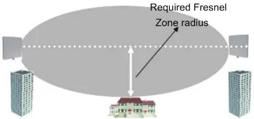
Fresnel Zone Radius:
| Range Distance between antennas | Required Fresnel Zone Radius (2.4GHz Radius) | Required Fresnel Zone Radius (5GHz Radius) |
| 300m 3.06m 2 | 12m | |
| 1.6Km 7.07m 4 | 9m | |
| 8Km 15.81m 1 | 0.95m | |
| 10Km 17.68m | 12.25m | |
| 15Km 21.65m | 15m |
 |  | ∞∞ | Δ+0 | ∞∞ | [28ZA] |  | |
| Model Name ANT24-0230 ANT24-0401 | ANT24-0500 ANT24-0501 | ANT24-0501C | ANT24-0502 ANT24-0600 | ||||
| Frequency 2.4GHz 2.4GHz 2.4GHz 2.4GHz 2.4GHz 2.4GHz 2.4GHz 2.4GHz 2.4GHz 2.4GHz 2.4GHz 2.4GHz 2.4GHz 2.4GHz 2.4GHz 2.4GHz 2.4GHz 2.4GHz 2.4GHz 2.4GHz 2.4 GHz 2.4GHz 2.4GHz 2.4GHz 2.4GHz 2.4GHz 2.4GHz 2.4GHz 2.4GHz 2.4GHz 2.4GHz 2.4GHz 2.4GHz 2.4GHz 2.4GHz 2.4GHz 2.4GHz 2.4GHz 2.4GHz 2.4GHz 2.4Ghz 2.4GHz 2.4GHz 2.4GHz 2.4GHz 2.4GHz 2.4GHz 2.4GHz 2.4GHz 2.4GHz 2.4GHz 2.4GHz 2.4GHz 2.4GHz 2.4GHz 2.4GHz 2.4GHz 2.4GHz 2.4GHz 2.4GHz 2.4Hz 2.4Hz 2.4Hz 2.4Hz 2.4Hz 2.4Hz 2.4Hz 2.4Hz 2.4Hz 2.4Hz 2.4Hz 2.4Hz 2.4Hz 2.4Hz 2.4Hz 2.4Hz 2.4Hz 2.4Hz 2.4Hz 2.4Hz 2.4kHz 2.4kHz 2.4kHz 2.4kHz 2.4kHz 2.4kHz 2.4kHz 2.4kHz 2.4kHz 2.4kHz 2.4kHz 2.4kHz 2.4kHz 2.4kHz 2.4kHz 2.4kHz 2.4kHz 2.4kHz 2.4kHz 2.4kHz 2.4 kHz 2.4 kHz 2.4 kHz 2.4 kHz 2.4 kHz 2.4 kHz 2.4 kHz 2.4 kHz 2.4 kHz 2.4 kHz 2.4 kHz 2.4 kHz 2.4 kHz 2.4 kHz 2.4 kHz 2.4 kHz 2.4 kHz 2.4 kHz 2.4 kHz 2.4 kHz 2.4kHz 2.4kHz 2.4kHz 2.4kHz 2.4kHz 2.4kHz 2.4kHz 2.4kHz 2.4kHz 2.4kHz 2.4kHz 2.4kHz 2.4kHz 2.4kHz 2.4kHz 2.4kHz 2.4kHz 2.4kHz 2.4kHz 2.4kV 2.4kV 2.4kV 2.4kV 2.4kV 2.4kV 2.4kV 2.4kV 2.4kV 2.4kV 2.4kV 2.4kV 2.4kV 2.4kV 2.4kV 2.4kV 2.4kV 2. | |||||||
| Signal directivity | Omni-directional | Omni-directional | Omni-directional | Omni-directional | Omni-directional | Omni-directional | Directional Antenna |
| Application range | Indoor | Indoor ceiling only | Indoor/ Outdoor | Indoor only | Indoor only | Indoor | Indoor only |
| Gain (Without cable loss) | 1.8dBi | 3.5dBi | 5dBi | 5dBi | 5dBi | 5dBi | 6dBi |
| Approximate Range at 1 / 11/ 54Mbps( Works with Indoor AP ) | 500m /400m /200m/100m /5m** | 250m/100m / 40 m | 500m/ 250m/ 60m | 500m/ 200m/ 50m | 550m/ 250m/ 60m | 500m/ 200m /60m | 600m/ 350m /80m |
| Approximate Range at 1/ 11 /54Mbps(Works with Outdoor AP) | --- | --- | 1.5Km/ 1.3Km/ 200m | --- | --- | --- | --- |
| Half Power Beam width | H360 V70 | H360 V120 | H360 V32 | H360 V36 | H360 V36 | H360 V40 | H68 V80 |
| Pigtail cable length | 1.2 m | --- | 30cm | 150cm | --- | --- | 150cm |
| Antenna fixed connector | PR-SMA plug | SMA jack | N-jack | RP-SMA plug | RP-SMA plug | RP-SMA plug | RP-SMA plug |
| Surge protector for outdoors | --- | --- | Optional | --- | --- | --- | --- |
| Default extension cable length | --- | 2M | 3M | --- | --- | --- | --- |
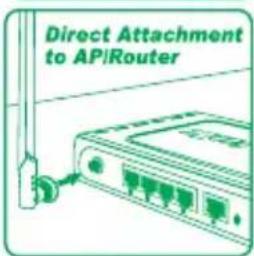
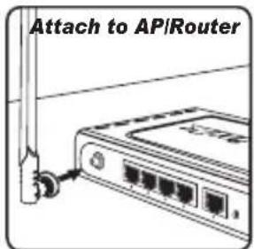
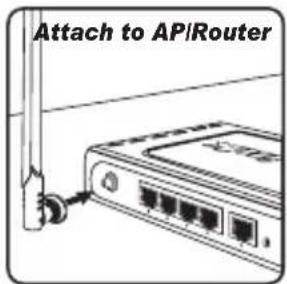
| Default mounting configuration | Desktop | Ceiling | Pole | Wall / desktop/magnetic | Attach to AP/Router | Attach to AP/Router | Wall/ desktop/magnetic |
| Optional accessories | --- | --- | ANT24-SP | --- | --- | --- | --- |
| Optional antenna cable kits | --- | --- | ANT24-CB series | --- | --- | --- | --- |
| (H3HT) | *** | (H42Y) | (xz85) | (4CK3) |  | |
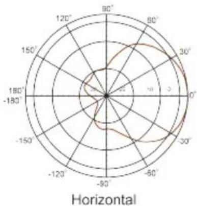
| Model Name | ANT24-0700 | ANT24-0700C | ANT24-0800 | ANT24-0801 | ANT24-1200 | ANT24-1201 |
| Frequency 2.4GHz 2.4GHz 2.4GHz 2.4GHz 2.4GHz | 2.4GHz | |||||
| Signal directivity Omni-directional Omni-directional Omni-directional Directional Directional | ||||||
| Application range Indoor only Indoor only Indoor/ Outdoor Indoor/ Outdoor | Indoor only Outdoor | |||||
| Gain (Without cable loss) | 7dBi | 7dBi | 8dBi | 8.5dBi | 12dBi | 12dBi |
| Approximate Range at 1 / 11/ 54Mbps( Works with Indoor AP ) | 550m/ 250m/60m | 600m/ 300m/ 70m | 700m/ 350m/ 100m | 800m/ 500m/ 150m | 1.5Km / 1.2Km/ 500m | --- |
| Approximate Range at 1/ 11 /54Mbps(Works with Outdoor AP) | --- | --- | 2Km / 1Km/ 400m | 2.5Km / 1.5Km/ 600m | --- | 3Km / 2.5Km/ 1Km |
| Half Power Beam width | H360 V24 | H360 V24 | H360 V15 | H70 V65 | H80 V23 | H50 V50 |
| Pigtail cable length | 150cm | 150cm | NA | 30cm | NA | 30cm |
| Antenna fixed connector | RP-SMA plug | RP-SMA plug | N-jack | N-jack | SMA jack | N-jack |
| Surge protector for outdoors | --- | --- | Included | Included | --- | Included |
| Default extension cable length | --- | --- | 50cm | 3M | 3M | 50cm |
| Default mounting configuration | Wall/ desktop/magnetic | Attach to AP/Router | Pole | Wall/ pole | Window/ wall | Wall/ pole |
| Optional accessories | --- | --- | --- | --- | --- | --- |
| Optional antenna cable kits | --- | --- | ANT24-CB series | ANT24-CB series | --- | ANT24-CB series |
| Model Name ANT24-1202 ANT24-1400 ANT24-1800 ANT24-2100 | ||||
| Frequency 2.4GHz 2.4GHz 4.6GHz 2.4GHz | ||||
| Signal directivity Omni-directional Directional Directional Directional | ||||
| Application range Outdoor Outdoor Outdoor Outdoor | ||||
| Gain (Without cable loss) 12dBi 14dBi 18dBi 21dBi | ||||
| Approximate Range at 1/11/54Mbps(Works with Indoor AP) | --- --- --- --- | |||
| Approximate Range at 1/11/54Mbps(Works with Outdoor AP) | 3Km / 1.8Km/ 450m 6Km | /4.5Km/ 1Km 8Km / 6Km/ 1.5Km | 8Km / 6Km/ 1.5Km | |
| Half Power Beam width | H360 V6 | H30 V30 | H15 V15 | H10 V12 |
| Pigtail cable length | 30cm | 30cm | --- | 31.5CM |
| Antenna fixed connector | N-jack | N-jack | N-jack | N-jack |
| Surge protector for outdoors | Included | Included | Included | Included |
| Default extension cable length | 50cm | 50cm | 50cm | 50cm |
| Default mounting configuration | Wall/ pole | Wall/ pole | Wall/ pole | Pole |
| Optional accessories | --- --- --- --- | |||
| Optional antenna cable kits | ANT24-CB series | ANT24-CB series | ANT24-CB series | ANT24-CB series |
| Model Name ANT70-0800 ANT70-0801 ANT70-1000 ANT70-1800 | ||||
| Frequency 2.4GHz/ 5GHz 2.4GHz/ 5GHz 2.4GHz/ 5GHz 2.4GHz/ 5GHz | ||||
| Signal directivity Omni-Directional Omni-Directional Directional Directional Directional Directional Directional Directional Directional Directional Directional Directional Directional Directional Directional Directional Directional Directional Directional Directional Directional Directional Directional Directional Directional Directional Directional Directional Directional Directional Directional Directional Directional Directional Directional Directional Directional Directional Directional Directional Directional Directional Directional Directional Directional Directional Directional Directional Directional Directional Directional Directional | 2.4GHz: 8dBi5GHz: 8dBi | 2.4GHz: 8dBi5GHz: 8dBi | 2.4GHz: 8dBi5GHz: 10dBi | 2.4GHz: 14Bi5GHz: 18dBi |
| Gain (Without cable loss) | 2.4GHz: 8dBi5GHz: 8dBi | 2.4GHz: 8dBi5GHz: 8dBi | 2.4GHz: 8dBi5GHz: 10dBi | 2.4GHz: 14Bi5GHz: 18dBi |
| Approximate Range at 1 / 11/ 54Mbps( Works with Indoor AP ) | 2.4GHz: 700m/ 350m/ 100m5GHz: 1K/ 500m/ 200m | 2.4GHz: 700m/ 350m/ 100m5GHz: 1K/ 500m/ 200m | 2.4GHz: 800m/ 400m/ 150m5GHz: 1.2K/ 600m/ 250m | --- |
| Approximate Range at 1/ 11/54Mbps(Works with Outdoor AP) | 2.4GHz: 800m/ 450m/ 150m5GHz: 1K/ 500m/ 200m | 2.4GHz: 800m/ 450m/ 150m5GHz: 1K/ 500m/ 200m | 2.4GHz: 1K/ 500m/ 200m5GHz: 1.5K/ 700m/ 300m | 2.4GHz: 6K/ 4.5m/ 1Km5GHz: 8Km/ 5Km/ 1.5Km |
| Half Power Beam width | 2.4GHz: H360 V155GHz: H360 V15 | 2.4GHz: H360 V155GHz: H360 V15 | 2.4GHz: H58 V555GHz: H45 V45 | 2.4GHz: H30 V305GHz: H15 V15 |
| Pigtail cable length NA NA NA NA | ||||
| Antenna fixed connector | N-jack | N-jack | N-jack | N-jack |
| Surge protector for outdoors | Included | Included | Included | Included |
| Default extension cable length | 50cm | 50cm | 50cm | 50cm |
| Default mounting configuration | Pole | Pole | Pole | Pole |
| Optional accessories | --- | --- | --- | --- |
| Optional antenna cable kits | ANT24-CB series | ANT24-CB series | ANT24-CB series | ANT24-CB series |
NOTE:
*1. Extended range reference based on RF-Output Power 16dbm( Indoor AP), 23 ( outdoor AP) with default cable loss,
*2. The transmission distance range might depend on the two same spec antennas with default cable loss under free line-of-sight environment.
*3. Effective range based on EIRP( Effected Isotropic Radiation Power. = device output power + antenna gain - cable lost )
**BW: Beam Width. H : horizontal plane pattern, V : vertical plane pattern
The actual range will be effected by users' physical environment. The above figures are reference.
(Appendix)
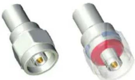
CONNECTORS OUTLOOK
RP N-Jack
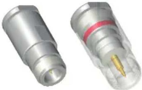
natural_image
Two metallic connectors with internal components, one showing a yellow tip and the other a red ring (no text or symbols visible)RP=TNC Plug
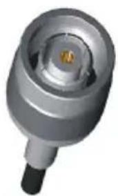
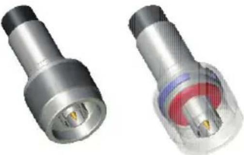
natural_image
Close-up of a metallic cylindrical mechanical component with a black end cap and central hub (no visible text or symbols)N Jack
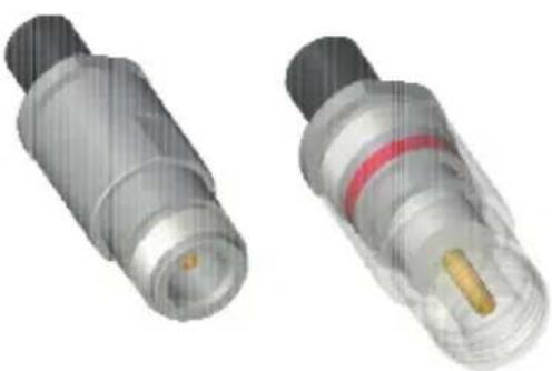
natural_image
Two metallic cylindrical connectors with black caps and red ring, one with a yellow internal component (no text or symbols visible)RP=SMA Plug RP-SMA Jack (D-Link AP/Router)

RP=N Plug
natural_image
Two metallic coaxial connectors with internal gold contacts and a red circular housing (no text or symbols visible)N Plug
natural_image
Two metallic cylindrical connectors with internal components, one showing a yellow flame symbol (no text or labels visible)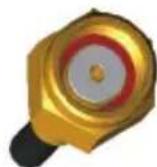
Ver. 3.00
DFWWANT00C0030
- User's Guid
- D-Link Antenna-kit Installation Guide
- Regulations
- D-Link WLAN Antenna-Kit
- Extended range differentiation for FCC/CE regulated regions
- CE ETSI EN 300 328 regulated European Union (EU) regions
- FCC regulated regions (US, Canada, etc.)
- Outdoor Installations
- Note:
- D-Link ANT24-0230 Indoor MIMO Antenna
- Package Contents:
- D-Link ANT24-0401 Ceiling Mount Antenna
- Installation Note:
- D-Link ANT24-0500Indoor/Outdoor Omni-Directional Antenna
- CAUTION:
- D-Link ANT24-0501 Indoor Omni-Directional Antenna
- Package Contents
- D-Link ANT24-0501C Indoor Omni-Directional Antenna
- D-Link ANT24-0502
- Indoor Omni-Directional Antenna
- D-Link DWL-50AT Indoor Omni-Directional Antenna
- Installation:
- D-Link ANT24-0600 Indoor Directional Antenna
- D-Link ANT24-0700
- D-Link ANT24-0700C Indoor Omni-Directional Antenna
- D-Link ANT24-0800 Indoor/Outdoor Omni-Directional Antenna
- Environmental & Mechanical Characteristics
- D-Link ANT24-0801Indoor/Outdoor Directional Panel Antenna
- D-Link ANT24-1200
- Indoor Directional Panel Antenna
- D-Link ANT24-1201
- Outdoor Directional Yagi Antenna
- D-Link ANT24-1202 Outdoor Omni-Directional Antenna
- D-Link ANT24-1400
- Outdoor Directional Panel Antenna
- D-Link ANT24-1800
- D-Link ANT24-2100
- Outdoor Directional Antenna
- D-Link ANT70-0800
- Dual-Band Omni-Directional Antenna
- D-Link ANT70-0801
- Dual-Band Directional Panel Antenna
- D-Link ANT70-1800
- Line-of-Sight (LOS)
- Fresnel Zone:
- Fresnel Zone
- (Appendix)
- CONNECTORS OUTLOOK
Brand : D-LINK
Model : ANT24-0800
Category : TV Antenna