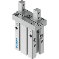
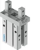
DHPC-20-A-S - Préenseur pneumatique Festo - Free user manual and instructions
Find the device manual for free DHPC-20-A-S Festo in PDF.


| Product Type | Pneumatic Parallel Gripper |
| Model | DHPC-20-A-S |
| Size | 20 |
| Pneumatic Port | M5 |
| Operating Pressure | 0.1 ... 0.8 MPa 1 ... 8 bar 15 ... 116 psi |
| Gripping Force (at 0.6 MPa / 6 bar) | Open: 192.6 N Close: 159.5 N |
| Ambient Temperature Range | -10 ... +60 °C |
| Storage Temperature Range | -10 ... +80 °C |
| Operating Medium | Compressed air to ISO 8573-1:2010 [7:4:4] |
| Mounting Position | Any |
| Function | Double-acting (with spring return for NC/NO variants) |
| Maintenance | Clean with non-abrasive agents and soft cloths. Store in cool, dry, UV-protected environment. |
| Safety Precautions | Remove payload before exhausting. Disconnect compressed air supply before mounting, installation, or maintenance. |
| Repair and Spare Parts | Send to Festo repair service. Spare parts available at www.festo.com/spareparts. |
| Intended Use | Gripping and holding payloads (workpieces) using custom-designed gripper fingers. |
Frequently Asked Questions - DHPC-20-A-S Festo
User questions about DHPC-20-A-S Festo
0 question about this device. Answer the ones you know or ask your own.
Ask a new question about this device
Download the instructions for your Préenseur pneumatique in PDF format for free! Find your manual DHPC-20-A-S - Festo and take your electronic device back in hand. On this page are published all the documents necessary for the use of your device. DHPC-20-A-S by Festo.
USER MANUAL DHPC-20-A-S Festo
Operating instructions
8150807
2021-05a
[8150809]

8150807
Translation of the original instructions
© 2021 all rights reserved to Festo SE & Co. KG
1 Applicable Documents
i
All available documents for the product → www.festo.com/sp.
2 Safety
2.1 Safety Instructions
- Take into consideration the ambient conditions at the location of use.
-Only use the product in original status without unauthorised modifications.
-Observe labelling on the product. - Store the product in a cool, dry, UV-protected and corrosion-protected environment. Ensure that storage times are kept to a minimum.
- Prior to mounting, installation and maintenance work: Switch off compressed air supply and secure it from being switched back on.
-Observe tightening torques. Unless otherwise specified, the tolerance is ± 20% .
2.2 Intended use
The intended use of the product is to grip and hold payloads (workpieces) using custom-designed gripper fingers attached by the customer.
2.3 Training of qualified personnel
Installation, commissioning, maintenance and disassembly should only be conducted by qualified personnel.
The specialized personnel must be familiar with the installation and operation of electrical and pneumatic control systems.
3 Additional information
- Contact the regional Festo contact if you have technical problems
→ www.festo.com.
-Accessories and spare parts → www.festo.com/catalogue.
4 Product overview
4.1 Function
- Alternating pressurisation of the supply ports causes a piston in the gripper to move (double-acting).
- A gripper with integrated spring return is used to exert the gripper force. When exhausting the single-acting gripper: the spring return moves the gripper jaws to the initial position.
-N/O contact: NO (normally open)
-N/C contact: NC (normally closed)
- The piston movement is transmitted mechanically to the gripper jaws. Gripper fingers are fastened to the gripper jaws. Closing or opening the gripper fingers clamps the payload to the outer contour (external gripping) or the inner contour (internal gripping).
- The gripping force is adjusted by external regulation of the operating pressure.
-The gripper has integrated fixed flow restrictors. If the max. gripper finger weights and the max. gripper finger lengths are in compliance, an external flow control is not required.
4.2 Structure

1
Gripper jaw
2
Threaded hole for mounting
3
Locating hole
4
Supply port
5
Slot for proximity switch
Fig. 1: Structure
5 Assembly
5.1 Preparing the gripper fingers
i
The gripper fingers are not included in the delivery.
Requirements for the gripper fingers → 11 Technical data:
- Observe the max. permissible forces and max. permissible torques at the gripper jaw.
-Observe the max. length and max. weight. - Use gripper fingers that are as short and light as possible.
- Manufacture gripper fingers that are suitable for the payload and type of gripping action.
| Size 6 10 16 | |||
| Width at gripper jaws [mm] 4.3 | -0.05 | 5.4-0.05 | 7-0.05 |
Tab. 1: Width of gripper jaws
| Size 20 25 32 40 | ||||
| Width at gripper jaws [mm] 8.3 | -0.05 | 12-0.05 | 15.2-0.05 | 18-0.05 |
Tab. 2: Width of gripper jaws
5.2 Mounting the gripper fingers

Fig. 2: Mounting the gripper fingers
1 Screw
2 Gripper finger
3 Gripper jaw A
4
Gripper jaw A-...-1
5
Gripper jaw A-...-2
- Position the prepared gripper fingers [2] on the gripper jaws [3], [4], [5] and fasten each one with two screws [1]. Fix the gripper jaws in place during mounting and use the specified tightening torque.
Tab. 3: Dimensions and tightening torque
Tab. 4: Dimensions and tightening torque
Tab. 5: Dimensions and tightening torque
Tab. 6: Dimensions and tightening torque
5.3 Mounting gripper
If necessary, mount the proximity switches before mounting the gripper. When using proximity switches for sensing the end position, take the following into account:
- Interference from ferritic attachments, e.g. retaining screws made of ferritic steel.
- Projecting proximity switches, if applicable.
- Cable outlet direction of the proximity switches.
- Sufficient space for the connection components.
- When sensing from both end positions: use separate slots for the proximity switches.
Vertical mounting

1 Thread
2 Locating hole
Fig. 3: Direct mounting via thread in the housing
| Size | 6 | 10 | 16 | 20 | 25 | 32 | 40 | |
| Thread [1] | M3 | M4 | M5 | M6 | M8 | |||
| Depth of thread | 10 | 4.75 | 6.75 | 9.6 | 13 | 15 | 18 | |
| Tightening torque | [Nm] | 0.88 | 0.69 | 2.1 | 4.3 | 7.9 | 10 | 18 |
| Locating hole ø for centring pin [2] | [mm] | - | 2^H9 | 3^H9 | 4^H9 | 5^H9 | ||
| Depth of locating hole | [mm] | - | 3 | 4 | 5 | |||
Tab. 7: Direct mounting via thread in the housing

1 Thread
2 Locating hole (not for size 6)
3 Depth of locating hole (not for size 6)
Fig. 4: Direct mounting via through-hole
| Size | 6 | 10 | 16 | 20 | 25 | 32 | 40 | |
| Thread [1] | M2.5 | M2.5 | M3 | M4 | M5 | M6 | ||
| Tightening torque | [Nm] | 0.49 | 0.49 | 0.88 | 2.1 | 4.3 | 7.3 | |
| Locating hole ø for centring pin [2] | [mm] | - | 2^H9 | 3^H9 | 4^H9 | 5^H9 | ||
| Depth of locating hole [3] | [mm] | - | 3 | 4 | 5 | |||
Tab. 8: Direct mounting via through-hole
Horizontal mounting

Fig. 5: Horizontal mounting
1 Locating hole (not for size 6)
2 Thread
| Size | 6 | 10 | 16 | 20 | 25 | 32 | 40 | |
| Thread [2] | M2 | M3 | M4 | M5 | M6 | M8 | ||
| Thread depth | [mm] | 4.5 | 4 | 4.5 | 7.5 | 10 | 13 | |
| Tightening torque | [Nm] | 0.15 | 0.9 | 1.6 | 3.3 | 5.9 | 13.7 | |
| Locating hole ø for centring pin [1] | [mm] | - | 2^H9 | 3^H9 | 4^H9 | 5^H9 | ||
| Depth of locating hole | [mm] | - | 3 | 3 | 4 | 5 | ||
Tab. 9: Horizontal mounting
Mounting on the bottom


natural_image
Technical line drawing of a mechanical assembly with mounting base and cylindrical component (no text or symbols)Fig. 6: Mounting on the bottom
1 Thread
2 Locating hole (not for size 6)
3 Positioning via base provided by customer
4 Axial mounting by customer
| Size | 6 | 10 | 16 | 20 | 25 | 32 | 40 | |
| Thread [1] | - | M3 | M4 | M5 | M6 | M8 | ||
| Thread depth | [mm] | - | 4 | 6 | 10 | 12 | 13 | 17 |
| Tightening torque | [Nm] | - | 0.88 | 2.1 | 4.3 | 7.3 | 7.9 | 17.7 |
| Locating holeø for centring pin [2] | [mm] | - | 2^H9 | 3^H9 | 4^H9 | 5^H9 | ||
| Depth of locating hole | [mm] | - | 3 | 4 | 5 | |||
| Positioning via base provided by customer [3] | ||||||||
| Locating holeø | [mm] | - | 12^H9 | 17^H8 | 21^H8 | 26^H8 | 33^H9 | 41^H9 |
| Depth of locating hole | [mm] | - | 1.5 | 2 | 3 | 3.5 | 4 | |
| Axial mounting by customer [4] | ||||||||
| Clamping surfaceø | [mm] | 8_f8 | 12_f8 | 16_f8 | 20_f8 | 25_f8 | 32_f8 | |
| Clamping surface height | [mm] | 10 | 15 | 18 | 20 | 23 | ||
Tab. 10: Mounting on the bottom
6 Installation
6.1 Pneumatic installation
NOTICE
Loss of function due to contamination in the connections.
- Keep ports and tubing lines free from dirt particles and foreign matter.
i
The use of a check valve prevents the payload from dropping in the event of a sudden pressure drop. The use of a one-way flow control valve also permits adjustment of the opening and closing time.
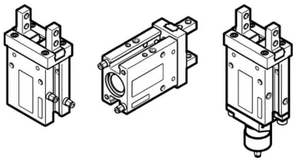
Fig. 7: Connection options
- Connect the compressed air supply to the supply port.
7 Commissioning
WARNING
Risk of injury due to falling loads.
- Before exhausting remove the payload.
- Slowly pressurise gripper.
- Set the opening and closing time with an upstream one-way flow control valve: screw in the flow control screw completely and then unscrew it one turn.
- Perform a test run without payload.
Check the following:
- Allocation of the supply ports
–The reliable function of the proximity switches (if installed) - Stop noise of the piston: the piston stop must be soft, that means not audibly hard or metallic.
Piston stop Insight/conclusion
| soft The gripper speed is correct | or can be increased. With upstream one-way flow control valve: unscrew the flow control screw slightly. ➔ The gripper speed increases. |
| hard/metallic The gripper speed | is too high. With an upstream one-way flow control valve: screw in the flow control screw until the piston stop is no longer audibly hard or metallic. ➔ The gripper speed is reduced. |
- Perform a test run with payload.
The gripper must hold the payload securely.
-
After successful test runs:
-
Remove the payload or lock to prevent it from falling.
-Exhaust the gripper.
8 Maintenance
8.1 Safety
WARNING
Risk of injury due to unexpected movement of the gripper fingers or falling payload.
- Before exhausting: remove the payload at the gripper.
- Disconnect gripper from the compressed air supply.
8.2 Cleaning
Clean the product only with non-abrasive cleaning agents and soft cloths.
9 Malfunctions
9.1 Fault clearance
| Error description Cause Remedy | ||
| Gripper does not hold payload securely. | Insufficient operating pressure. Increase the operating pressure. Observe the max. permissible value. | |
| The pressure point of the gripper fingers is too far outwards. | Move the pressure point inwards. | |
| The payload is too heavy. Select a larger gripper. | ||
| Gripping only with return spring force with incorrect gripping direction. | Use the intended gripping direction. | |
| The gripper does not open/ close. | No compressed air. | Check the supply ports. |
| The gripper is faulty. | Replace the faulty parts → www.festo.com/spareparts. Replace the gripper → 9.2 Repair. | |
| The proximity switch does not indicate the gripper status. | The proximity switch is incorrectly adjusted. | Check and adjust the position of the proximity switch → www.festo.com/sp. |
| The connecting cable is disconnected. | Replace the connecting cable or proximity switch → . | |
Tab. 11: Fault clearance
9.2 Repair
Send the product to the Festo repair service for repair.
10
Disassembly

WARNING
Risk of injury due to unexpected movement of the gripper fingers or falling payload.
- Before exhausting: remove the payload at the gripper.
-
Disconnect gripper from the compressed air supply.
-
Disconnect the gripper from the compressed air supply.
- Remove the supply ports and retaining screws.
11 Technical data
| Size | 6 10 | 16 | ||
| Pneumatic port | M3 | M3 | M3 | |
| Mounting position any | ||||
| Medium | ||||
| Operating medium | Compressed air to ISO 8573-1:2010 [7:4:4] | |||
| Notes on the operating/pilot medium | lubricated operation possible, in which case lubricated operation will always be required | |||
| Temperature | ||||
| Ambient temperature | [°C] | -10 ... +60 | ||
| Storage temperature | [°C] | -10 ... +80 | ||
| Operating pressure | ||||
| DHPC-...-A | [MPa] | 0.15 ... 0.8 | 0.2 ... 0.8 | 0.1 ... 0.8 |
| [bar] | 1.5 ... 8 | 2 ... 8 | 1 ... 8 | |
| [psi] | 22 ... 116 30 ... 116 | 15 ... 116 | ||
| DHPC-L-...-A | [MPa] | - | 0.2 ... 0.8 | 0.1 ... 0.8 |
| [bar] | - | 2 ... 8 | 1 ... 8 | |
| [psi] | - | 30 ... 116 15 ... 116 | ||
| DHPC-...-A-NO/-NC | [MPa] | 0.35 ... 0.8 | 0.35 ... 0.8 | 0.25 ... 8 |
| [bar] | 3.5 ... 8 | 3.5 ... 8 | 2.5 ... 8 | |
| [psi] | 51 ... 116 51 ... 116 | 37 ... 116 | ||
| Total gripping force at 0.6 MPa (6 bar, 90 psi) | ||||
| DHPC-...-A | ||||
| Open [N] | 14.6 | 51.2 | 125.4 | |
| Close [N] | 11 | 43 | 107.8 | |
| DHPC-...-A-NO | ||||
| Close [N] | 7.8 | 32.8 | 86.8 | |
| DHPC-...-A-NC | ||||
| Open [N] | 10.4 | 39.2 | 101 | |
Tab. 12: Technical data
| Size | 20 | 25 | 32 | 40 | |
| Pneumatic port | M5 | M5 | M5 | M5 | |
| Mounting position any | |||||
| Medium | |||||
| Operating medium | Compressed air to ISO 8573-1:2010 [7:4:4] | ||||
| Notes on the operating/pilot medium | lubricated operation possible, in which case lubricated operation will always be required | ||||
| Temperature | |||||
| Ambient temperature | [°C] | -10 ... +60 | |||
| Storage temperature | [°C] | -10 ... +80 | |||
| Operating pressure | |||||
| DHPC-...-A | [MPa] | 0.1 ... 0.8 | 0.1 ... 0.8 | 0.1 ... 0.8 | 0.1 ... 0.8 |
| [bar] | 1 ... 8 | 1 ... 8 | 1 ... 8 | 1 ... 8 | |
| [psi] | 15 ... 116 | 15 ... 116 | 15 ... 116 | 15 ... 116 | |
| DHPC-L-...-A | [MPa] | 0.1 ... 0.8 | 0.1 ... 0.8 | - | - |
| [bar] | 1 ... 8 | 1 ... 8 | - | - | |
| [psi] | 15 ... 116 | 15 ... 116 | - | - | |
| DHPC-...-A-NO/-NC | [MPa] | 0.25 ... 0.8 | 0.25 ... 0.8 | 0.25 ... 0.8 | 0.25 ... 0.8 |
| [bar] | 2.5 ... 8 | 2.5 ... 8 | 2.5 ... 8 | 2.5 ... 8 | |
| [psi] | 37 ... 116 | 37 ... 116 | 37 ... 116 | 37 ... 116 | |
| Total gripping force at 0.6 MPa (6 bar, 90 psi) | |||||
| DHPC-...-A | |||||
| Open | [N] | 192.6 | 305.3 | 493.7 | 777.2 |
| Close [N] 159.5 | 255.6 | 442.6 | 717.2 | ||
| DHPC-...-A-NO | |||||
| Close [N] 139.4 | 241.3 | 415.2 | 675 | ||
| DHPC-...-A-NC | |||||
| Open | [N] | 170.9 | 291.4 | 465.9 | 733.5 |
Tab. 13: Technical data


- Applicable Documents
- Safety
- Safety Instructions
- Intended use
- Training of qualified personnel
- Additional information
- Product overview
- Function
- Assembly
- Preparing the gripper fingers
- Mounting gripper
- Installation
- Pneumatic installation
- NOTICE
- Commissioning
- WARNING
- Risk of injury due to falling loads.
- Maintenance
- Safety
- Cleaning
- Malfunctions
- Repair
- Disassembly
- Risk of injury due to unexpected movement of the gripper fingers or falling payload.
Brand : Festo
Model : DHPC-20-A-S
Category : Préenseur pneumatique