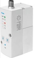
VPPM-8 - Pressure regulator Festo - Free user manual and instructions
Find the device manual for free VPPM-8 Festo in PDF.


| Product Type | Pneumatic pressure regulator |
| Brand | Festo |
| Model | VPPM-8 |
| Operating Pressure Range | 0.5 to 8 bar |
| Flow Rate | Up to 800 l/min |
| Connection Size | G1/8 or G1/4 (depending on variant) |
| Operating Temperature | 0°C to 60°C |
| Weight | Approx. 0.2 kg |
| Dimensions (HxWxD) | Approx. 60 x 30 x 30 mm |
| Supply Voltage | 24 V DC (if electrical connection) |
| Power Consumption | < 1 W |
| Material | Aluminum, plastic, stainless steel |
| Protection Class | IP40 |
| Functions | Pressure regulation, proportional control, switching |
| Maintenance | Clean air filter, check seals periodically |
| Safety | Do not exceed max pressure, use filtered air |
| Spare Parts | Seal kit, filter element |
| Reparability | Field-replaceable seals and filters |
| General Information | CE compliant, RoHS compliant |
Frequently Asked Questions - VPPM-8 Festo
User questions about VPPM-8 Festo
0 question about this device. Answer the ones you know or ask your own.
Ask a new question about this device
Download the instructions for your Pressure regulator in PDF format for free! Find your manual VPPM-8 - Festo and take your electronic device back in hand. On this page are published all the documents necessary for the use of your device. VPPM-8 by Festo.
USER MANUAL VPPM-8 Festo
Proportional-pressure regulator
FESTO
Festo SE & Co. KG
Ruiter Straße 82
73734 Esslingen
Deutschland
+49 711 347-0
www.festo.com
Operating instructions
8110177
2021-11g
[8110179]

8110177
Translation of the original instructions
© 2021 all rights reserved to Festo SE & Co. KG
1
Applicable Documents
□1
All available documents for the product → www.festo.com/sp.
2 Safety
2.1 Safety instructions
- Only use the product in its original condition without unauthorised modifications.
- Only use the product if it is in perfect technical condition.
- Take into account the ambient conditions at the location of use.
- Before working on the product, switch off the power supply and secure it against being switched on again.
-Store the product in a cool, dry environment protected from UV and corrosion. Keep storage times short.
2.2 Intended use
The proportional-pressure regulator is intended to regulate a pressure proportional to a specified setpoint value. The product is intended for use in industrial environments.
2.3 Training of qualified personnel
Work on the product may only be carried out by qualified personnel who can evaluate the work and detect dangers. The qualified personnel have skills and experience in dealing with electropneumatic (open-loop) control technology.
2.4 Approvals
In combination with the UL inspection mark on the product, the information in this section must also be observed in order to comply with the certification conditions of Underwriters Laboratories Inc. (UL) for USA and Canada.
UL certification information
| Product category code QUYX, QUYX7 | |
| File number E322J46 | |
| Considered standards UL 610101, CAN/CSAC22.2 | No. 610101 |
| UL mark |  US LISTED US LISTED |
Tab. 1: UL certification information
- The unit shall be supplied by a power source which fulfils the requirements on a limited-energy circuit in accordance to IEC/EN/UL/CSA 61010-1 or on a Limited Power Source (LPS) in accordance to IEC/EN/UL/CSA 60950-1 or IEC/EN/UL/CSA 62368-1 or a Class 2 circuit in accordance to NEC or CEC.
Electrical data and ambient conditions
| Supply voltage 24 V DC | |
| Max. power VPPM-6, VPPM-8 7 W | |
| Max. power VPPM-12 12 W | |
| Rated pressure up to 1.1 MPa | |
| Max. installation height 2000 m |
Tab. 2: Electrical data and ambient conditions
3 Additional information
-Contact the regional Festo contact if you have technical problems
→ www.festo.com.
-Accessories and spare parts → www.festo.com/catalogue.
4 Product overview
4.1 Function
The proportional-pressure regulator controls the pressure proportionally to a specified setpoint value. A built-in pressure sensor records the pressure at the working port and compares this value with the setpoint value. If there are deviations between the setpoint value and actual values, the proportional-pressure regulator is actuated until the output pressure has reached the setpoint.

Fig. 1: Pneumatic circuit symbol
4.2 Structure
4.2.1 Product design

Fig. 2: Connections and mounting holes (in-line valve)
1 Through-holes for fastening
2 Electrical connecting plug
3 Working air port (2)
4 Compressed air port (1)
5 Exhaust air port (3)
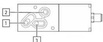
Fig. 3: Pneumatic ports (sub base valve)
1 Exhaust air port (3)
2 Working air port (2)
3 Compressed air port (1)
4.2.2 Display and control elements

Fig. 4: Display and control elements
1 [Edit] key
2 [UP] key
3 Yellow LED: precise control response
4 Yellow LED: universal control response (factory setting)
5 Yellow LED: fast control response
6 Red LED [error]
7 Green LED [power]
8 [DOWN] key
5 Transport
Store and transport the product in its original packaging. Observe the weight, the dimensions and the ambient conditions.
6 Assembly
6.1 Mounting clearances
During assembly make sure that there is sufficient space for the cable connection and the tubing connections. Place the device as close to the consumer as possible. This leads to better control accuracy and shorter response times.
6.2 Wall mounting (in-line valve)
VPPM-6L-... and VPPM-8L-...
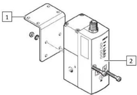
- Fasten the VPPM-... [2] with 2 M4 screws. If necessary, use the bracket VAME-P1-A [1].
Only apply a static load to the VPPM-... when mounting the VPPM-... with the assistance of the bracket.
VPPM-12L-...
• Fasten the VPPM-... with 2 M5 screws.
-Tightening torque: 2.0 Nm
6.3 H.rail mounting (in-line valve)
VPPM-6L-... and VPPM-8L-...
- Attach the H-rail adapter VAME-P1-T [2] to the VPPM-... with 2 screws [1].
-Screws: M4 x 65 for VPPM-6L-..., M4 x 77 for VPPM-8L-...
- Tightening torque: 1.5 Nm

2. Attach the VPPM -... to the H-rail.
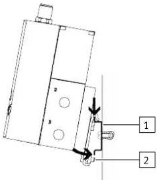
- Fasten the VPPM-... with the retaining screw [2] of the H-rail adapter.
- Tightening torque: 1.5 Nm
6.4 Manifold block assembly (sub base valve)
- Fasten the VPPM-... [2] to the manifold block [1] with 2 screws.
-Screws: M4 x 65 for VPPM-6F-..., M4 x 77 for VPPM-8F-...
-Tightening torque: 1.5 Nm

7 Installation
7.1 Pneumatic installation (in-line valve)
- Remove the covers from the supply ports.
- Connect the compressed air port (1) and the working air port (2) with tubing
→ Fig. 2.
- Fit a silencer at the exhaust air port (3) or install an exhaust air duct → Fig. 2.
Operating medium
NOTICE
Too much residual oil content in the compressed air will reduce the service life of the valve.
- When using bio-oils (oils that are based on synthetic ester or native ester, e.g. rapeseed oil methyl ester), the maximum residual oil content of 0.1mg / m^3 must not be exceeded (ISO 8573-1:2010 [-::-2]).
7.2 Electrical installation
WARNING
Risk of injury due to electric shock.
- For the electrical power supply, use only PELV circuits in accordance with IEC 60204-1/EN 60204-1 (Protective Extra-Low Voltage, PELV).
- Observe the general requirements of IEC 60204-1/EN 60204-1 for PELV circuits.
- Only use voltage sources that ensure a reliable electric separation from the mains network in accordance with IEC 60204-1/EN 60204-1.
NOTICE
Malfunction due to impaired immunity to interference
Long signal lines reduce the immunity to interference.
- Use the shortest possible signal lines.
NOTICE
- The connector must not be twisted out of the intended position.
- The tightening torque of the M12 plug socket with cable must not exceed 0.5 Nm.
NOTICE
If the Y-connecting cable type NEBV-M12G8-KD-..-M12G5 is connected to CPX I/O modules, galvanic isolation of the I/O modules will not be guaranteed.
- Use the rating plate to check which valve variant is involved.
Valve variant VPPM-...-V1... VPPM-...-A4...
| Voltage variant 0 ... 10 V DC | |
| Current variant 4 ... 20 mA |
- Lay the electrical connection cable without crushing, kinking or stretching it.
- If a shielded electrical connection cable is used, earth the shield at the end of the cable remote from the valve.
- Wire the VPPM-... according to the corresponding plug pattern.
VPPM-...-V1... VPPM-...-A4...

Pin allocation
The pins on the electrical connection are assigned as follows:
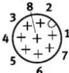
Fig. 5: Pin allocation
| PIN Wire colour 1) | Port identifications | ||
| VPPM-...-V1... VPPM-...-A4.. | |||
| 1 white | (WH) Digital input D1 | ||
| 2 brown | (BN) +24 V DC supply voltage | ||
| 3 green | (GN) Analogue input W- (- setpoint value) | ||
| 4 yellow | (YE) Analogue input W+ | (+ setpoint value)0 ... 10 V | Analogue input W+(+ setpoint value)4 ... 20 mA |
| 5 grey | (GY) Digital input D2 | ||
| 6 pink | (PK) Analogue output X (actual value) | ||
| 7 blue | (BU) GND supply earth | ||
| 8 red | (RD) Digital output D3 | 2) | |
1) With usage of the plug socket with cable as specified in accessories.
2) The hysteresis of the digital comparator output D3 is 0.5% FS.
Tab. 3: Pin allocation
Digital comparator output D3
The "Pressure reached" function permits monitoring of the pressure control function. The setpoint value is compared with the actual value.
The digital switching output D3 becomes active as soon as the divergence is
≤ 0.5% FS and becomes inactive when the divergence > 1% FS is exceeded.
Graph for VPPM-...-...P switching variant

line
| Point | Time (t) | U_B/Suit (%) | |---|---|---| | 1 | 0 | 0 | | 2 | 1 | +1 | | 3 | 2 | +1 | | 4 | 3 | +1 | | ... | ... | ... | | 5 | 4 | -1 | | ... | ... | ... | | 6 | 5 | -1 | | ... | ... | ... | | 7 | 6 | -1 | | ... | ... | ... | | 8 | 7 | -1 | | ... | ... | ... | | 9 | 8 | -1 | | ... | ... | ... | | 10 | 9 | -1 | | ... | ... | ... | | 11 | 10 | -1 | | ... | ... | ... | | 12 | 11 | -1 | | ... | ... | ... | | 13 | 12 | -1 | | ... | ... | ... | | 14 | 13 | -1 | | ... | ... | ... | | 15 | 14 | -1 | | ... | ... | ... | | 16 | 15 | -1 | | ... | ... | ... | | 17 | 16 | -1 | | ... | ... | ... | | 18 | 17 | -1 | | ... | ... | ... | | 19 | 18 | -1 | | ... | ... | ... | | 20 | 19 | -1 | | ... | ... | ... | | 21 | 20 | -1 | | ... | ... | ... | | 22 | 21 | -1 | | ... | ... | ... | | 23 | 22 | -1 | | ... | ... | ... | | 24 | 23 | -1 | | ... | ... | ... | | 25 | 24 | -1 | | ... | ... | ... | | 26 | 25 | -1 | | ... | ... | ... | | 27 | 26 | -1 | | ... | ... | ... | | 28 | 27 | -1 | | ... | ... | ... | | 29 | 28 | -1 | | ... | ... | ... | | 30 | 29 | -1 | | ... | ... | ... | | 31 | 30 | -1 | | ... | ... | ... | | 32 | 31 | -1 | | ... | ... | ... | | 33 | 32 | -1 | | ... | ... | ... | | 34 | 33 | -1 | | ... | ... | ... | | 35 | 34 | -1 | | ... | ... | ... | | 36 | 35 | -1 | | ... | ... | ... | | 37 | 36 | -1 | | ... | ... | ... | | 38 | 37 | -1 | | ... | ... | ... | | 39 | 38 | -1 | | ... | ... | ... | | 40 | 39 | -1 | | ... | ... | ... | | 41 | 40 | -1 | | ... | ... | ... | | 42 | 41 | -1 | | ... | ... | ... | | 43 | 42 | -1 | | ... | ... | ... | | 44 | 43 | -1 | | ... | ... | ... | | 45 | 44 | -1 | | ... | ... | ... | | 46 | 45 | -1 | | ... | ... | ... | | 47 | 46 | -1 | | ... | ... | ... | | 48 | 47 | -1 | | ... | ... | ... | | 49 | 48 | -1 | | ... | ... | ... | | 50 | 49 | -1 | | ... | ... | ... | | 51 | 50 | -1 | | ... |... | ... | | 52-53-54-55-56-57-58-59-60-61-62-63-64-65-66-67-68-69-70-71-72-73-74-75-76-77-78-79-80-81-82-83-84-85-86-87-88-89-90-91-92-93-94-95-96-97-98-99-100-1 Setpoint value
2 Actual value
3 Upper tolerance limit
4 Lower tolerance limit
Fig. 6: Switching variant VPPM-...-...P
Graph for VPPM-...-...N switching variant

line
| Point | Value | |---|---| | 1 | +1% | | 2 | +1% | | 3 | -1% | | 4 | -1% |1 Setpoint value
2 Actual value
3 Upper tolerance limit
4 Lower tolerance limit
Fig. 7: Switching variant VPPM-...-...N
Circuit diagram VPPM-...-...P Circuit diagram VPPM-...-...N

Tab. 4: VPPM-... circuit diagrams Switching output
8
Commissioning
i
- Keep high-frequency radiation away from the VPPM-... in order to avoid increased tolerances of the outlet pressure.
- The VPPM-... interprets setpoint signals that are less than 1% Full Scale (FS) as 0 V or 4 mA. In this case the working pressure is set to ambient pressure.
-
At typical input values below 3.6 mA, the valve detects a cable break and the last pressure set remains unregulated. Leakage results in a change of pressure over the long term.
-
Connect the VPPM-... with a setpoint value signal. The VPPM-... has a differential input. Apply the setpoint signal 0 ... 10 V or 4 ... 20 mA to contacts 3 and 4. Apply the lower potential to contact 3 and the higher potential to contact 4.
i
Contact 3 (− setpoint value) can be connected to contact 7 (GND).
- Power the VPPM-... with direct current.
Supply voltage UV = 24 V DC ±10%
-
Select a parameter set for the regulator.
-
Press and hold the [Edit] key for 3 seconds.
- Select a parameter set with the [UP] and [DOWN] keys. The LED of the selected parameter set lights up.
- Press the [Edit] key to confirm the selection.
i
The control response of the VPPM-... can also be set by remote control via digital inputs D1 and D2.
| Parameter set | Control response | Input D1 (PIN 1) | Input D2 (PIN 5) |
| 1 | Fast control response | 1 (24 V DC) | 0 (0 V DC) |
| 2 | Factory setting: universal control response | 0 | 1 |
| 3 | Precise control response 1 | 1 |
Tab. 5: Parameter sets
The following 3 tables show the recommended parameter sets for the different pneumatic ports:
Parameter sets recommended for VPPM-6...
| Tube length1) | Open system Output volume in ml | |||
| 0 ... 100 | 100 ... 1000 | >1000 | ||
| 0 m | 3 | 3 | 2 | 1 |
| 1 m | 3 | 3 | 2 | 2 |
| 3 m | 3 | 3 | 3 | 2 |
| ≥5 m | 3 | 3 | 3 | 2 |
1) with inner tubing diameter 6 mm or 8 mm
Tab. 6: Parameter sets recommended for VPPM-6...
Parameter sets recommended for VPPM-8...
| Tube length ^1) | Open system Output volume in ml | |||
| 0 ... 500 | 500 ... 2000 | >2000 | ||
| 0 m | 3 | 1 | 2 | 3 |
| 1 m | 3 | 1 | 2 | 3 |
| 3 m | 3 | 2 | 3 | 3 |
| >5 m | 3 | 3 | 3 | 3 |
1) with tubing diameter 8 mm or 10 mm
Tab. 7: Parameter sets recommended for VPPM-8...
Parameter sets recommended for VPPM-12L-...
| Tube length ^1) | Open system Output volume in ml | |||
| 0 ... 2000 | 2000 ... 10000 | >10000 | ||
| 0 m | 3 | 1 | 2 | 3 |
| 1 m | 3 | 1 | 2 | 3 |
| 3 m | 3 | 2 | 3 | 3 |
| ≥5 m | 3 | 3 | 3 | 3 |
1) with tubing diameter 12 mm or 16 mm
Tab. 8: Parameter sets recommended for VPPM-12L-...
9 Maintenance
9.1 Disassembly
NOTICE
- When switching off the VPPM.-..., first make sure that the setpoint value is set to 0, then that the supply pressure and finally the supply voltage are switched off.
-
Switch off the following energy sources:
-
Operating voltage
-
Compressed air
-
Disconnect the connections from the device.
- Remove the device from the mounting surface or H-rail.
9.2 Cleaning
-
Switch off the following energy sources to clean the outside:
-
Operating voltage
-
Compressed air
-
Clean the device on the outside with a soft cloth as required.
10 Malfunctions
Status of the LED displays
| Cause Green LED [power] | Red LED [error] | |
| -Undervoltage or overvoltage of the setpoint value | on on | |
| -Hardware error-Overvoltage (>30 V)-Internal temperature too high | on flashes | |
| -Undervoltage (<18 V) off off |
Tab. 9: Status of the LED displays
Fault clearance
| Malfunction Possible cause Remedy | ||
| Device does not respond No supply voltage, LED [power] off. | Check the connection of the supply voltage 24 V DC. | |
| No data communication. | ||
| Flow rate too low Restriction of the flow cross section by connection technology. | - Check control unit.-Check connection. | |
| Pressure rise too slow Large cylinder volume and long tube length. | Use alternative connections. | |
| Pressure constant despite modified setpoint specification | Break in the electrical connecting cable. | Select another parameter set. |
| Supply pressure P1 too low. Increase supply pressure. | ||
| Manual selection of parameter sets with the [UP] and [DOWN] keys on the device is not possible | Voltage is applied at digital inputs D1 and D2. | Apply 0 V DC at digital inputs D1 and D2. |
Tab. 10: Fault clearance
11 Technical data
| General technical data | |
| Design Proportional-pressure regulator | |
| Mounting position | As desired, preferably horizontal (display elements facing upwards) |
| Materials | |
| Housing | Wrought aluminium alloy |
| Cover | PAXMD6 GF50/gr-P |
| Seals | Nitrile rubber |
| Lubrication | silicone-free |
| Weight | |
| VPPM-6... [g] 400 | |
| VPPM-8... [g] 560 | |
| VPPM-12... [g] 2050 | |
Tab. 11: General technical data
Operating and environmental conditions
| Medium | Compressed air in accordance with ISO 8573-1:2010 [7:4:4] inert gases | |
| Information on operating medium | Lubricated operation not possible | |
| Degree of protection | IP 65 when mounted, with tightened mounting screws, in combination with plug socket according to accessories. | |
| Ambient temperature | [°C] | 0 ... 60 |
| Temperature of medium | [°C] | 10 ... 50 |
| Storage temperature | [°C] | -10 ... +70 |
| Vibration and shock | ||
| Vibration | Tested in accordance with DIN/IEC 68/EN 60068 Part 2-6; wall mounting: 0.35 mm path at 10 ... 60 Hz, 5 g acceleration at 60 ... 150 Hz^2) | |
| Shock | Tested in accordance with DIN/IEC 68/EN 60068 Part 2-27; wall mounting: ±30 g at 11 ms duration; 5 shocks per direction^1) | |
1) Information does not apply when mounting the VPPM-.../VPPX-... on bracket VAME-P1-A/-T.
Tab. 12: Operating and environmental conditions
| VPPM-... | 0L2H | 0L6H | 0L10H | |
| Pressure ranges | ||||
| Permissible input pressure P1 | [MPa] 0 ... | 0.4 0 ... 0.8 0 ... 1.1 | ||
| [bar] | 0 ... 4 | 0 ... 8 | 0 ... 11 | |
| [psi] | 0 ... 58 | 0 ... 116 | 0 ... 159.5 | |
| Control range (output pressure P2)1 | [MPa] 0.00 | 2 ... 0.2 0.00 | 6 ... 0.6 0.01 | 1 ... 1 |
| [bar] | 0.07 ... 2 0.06 ... 6 | 0.1 ... 10 | ||
| [psi] | 2.9 ... 29 8.7 ... 87 | 1.45 ... 145 | ||
| Total leakage when new | [l/h] | < 5 | ||
| Connection | G 1/8, 1/8 NPT, G 1/4, 1/4 NPT, G 1/2, 1/2 NPT | |||
| VPPM-... | 0L2H | 0L6H | 0L10H | |
| Nominal width | ||||
| Pressurisation | [mm] | 6 for VPPM-6...8 for VPPM-8...12 for VPPM-12... | ||
| Exhaust port | [mm] | 4.5 for VPPM-6...6 for VPPM-8...12 for VPPM-12... | ||
1) Input pressure P1 at least 0.1 MPa (1 bar, 14.5 psi) above output pressure P2.
Tab. 13: Characteristic pneumatic values
| Characteristic electrical values | ||
| Electrical connection | Pin contact M12x1, 8-pin | |
| Permissible operating voltage | [V DC] | 21.6 ... 26.4Permissible residual ripple max. 10% |
| Power rating of digital switching output D3 (PIN 8 in el. connection) | [mA] | max. 60 |
| Max. permissible supply line length and signal line length | [m] | 10 |
| Max. electrical power consumption | ||
| VPPM-6... and VPPM-8... | [W] | 7 |
| VPPM-12L.... | [W] | 12 |
| Voltage type VPPM-...-V1... | ||
| Setpoint variable | [V DC] | 0 ... 10 |
| Input resistance (setpoint value) | [kΩ] | 10 |
| Output actual value load | [kΩ] | min. 2 |
| Current type VPPM-...-A4... | ||
| Setpoint variable | [mA] | 4 ... 20 |
| Input resistance (setpoint value) | [Ω] | 250 |
| Output actual value load | [Ω] | max. 500 |
Tab. 14: Characteristic electrical values
| Control characteristics1) | |
| Linearity | 1% Full Scale (FS)/2% Full Scale (FS) |
| Hysteresis | 0.5% Full Scale (FS) |
| Reproducibility | 0.5% Full Scale (FS) |
| Total accuracy 1.25% (S1)/2.25 (2%) | |
| Temperature coefficient | 0.04/K |
1) Maximum deviation, characteristic values determined at room temperature in accordance with ISO 10094. Linearity refers to the ideal characteristic curve.
Tab. 15: Control characteristics



- Proportional-pressure regulator
- FESTO
- 1
- Applicable Documents
- Safety
- Safety instructions
- Intended use
- Training of qualified personnel
- Approvals
- Additional information
- Product overview
- Function
- Structure
- Product design
- Display and control elements
- Transport
- Assembly
- Mounting clearances
- Wall mounting (in-line valve)
- VPPM-6L-... and VPPM-8L-...
- VPPM-12L-...
- H.rail mounting (in-line valve)
- Attach the VPPM -... to the H-rail.
- Manifold block assembly (sub base valve)
- Installation
- Pneumatic installation (in-line valve)
- Operating medium
- NOTICE
- Electrical installation
- WARNING
- Risk of injury due to electric shock.
- Malfunction due to impaired immunity to interference
- Pin allocation
- Digital comparator output D3
- 8
- Commissioning
- i
- Maintenance
- Disassembly
- Cleaning
Brand : Festo
Model : VPPM-8
Category : Pressure regulator