
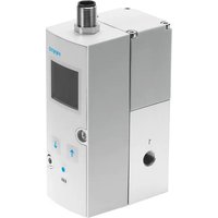
VPPI - Pressure regulator Festo - Free user manual and instructions
Find the device manual for free VPPI Festo in PDF.


| Product Type | Pressure Regulator with Filter |
| Manufacturer | Festo |
| Model | VPPI |
| Operating Pressure | 0.5 to 12 bar |
| Max. Inlet Pressure | 15 bar |
| Temperature Range | -10°C to +60°C |
| Fluid | Compressed air, inert gases |
| Port Size | G1/4, G1/2, G3/4 (depending on variant) |
| Filter Element | 5 µm or 40 µm (depending on variant) |
| Drain Type | Manual or semi-automatic |
| Adjustment | Knob with lock nut |
| Gauge Port | Integrated (optional gauge) |
| Materials | Die-cast aluminium, polyamide, NBR |
| Weight | 0.3 to 1.2 kg (depending on size) |
| Dimensions (W x H x D) | Approx. 80 x 160 x 60 mm (G1/2 variant) |
| Mounting | Inline, bracket mounting possible |
| Protection Class | IP40 |
| Standards | ISO 8573-1, Directive 2014/68/EU |
| Maintenance Interval | Every 6 months or as needed |
| Spare Parts | Filter elements, seals, drain kits available |
Frequently Asked Questions - VPPI Festo
User questions about VPPI Festo
0 question about this device. Answer the ones you know or ask your own.
Ask a new question about this device
Download the instructions for your Pressure regulator in PDF format for free! Find your manual VPPI - Festo and take your electronic device back in hand. On this page are published all the documents necessary for the use of your device. VPPI by Festo.
USER MANUAL VPPI Festo
natural_image
Technical line drawing of a mechanical device with ports and mounting holes (no text or symbols)FESTO
Operating instruction
Translation of the original instructions
Table of contents
1 About this document.... 4
1.1 Applicable documents....4
1.2 Product labelling.... 4
2 Safety....4
2.1 Safety instructions....4
2.2 Intended use.... 4
2.3 Training of qualified personnel....4
2.4 UL approvals....5
3 Additional information....5
4 Product overview....6
4.1 Product design....6
4.2 Function.... 6
5 Assembly....6
5.1 Preparation....6
5.2 Assembling....7
5.2.1 Creating pressure zones....7
5.2.2 Linkage of valves....7
5.3 Mounting....8
5.3.1 Mounting via bottom of valve....8
5.3.2 Mounting via valve side surface....9
5.3.3 Mounting on H-rail.... 9
5.4 Fitting....9
6 Installation....9
6.1 Installation, pneumatic....9
6.2 Electrical installation....10
7 Commissioning.... 10
8 Parameterisation.... 10
8.1 Function of the Operating Buttons.... 11
8.2 Menu Levels.... 11
8.3 Contents of the menu.... 12
9 Malfunctions....18
9.1 Diagnostics.... 18
9.2 Fault clearance....19
10 Disassembly.... 20
11 Technical data....20
11.1 Technical data, general.... 20
11.2 Technical data, pneumatic.... 25
11.3 Technical data, electrical....25
11.4 Technical data for UL certification.... 26
1 About this document
1.1 Applicable documents
| Document Product Content | ||
| Test report1) | Proportional-pressure regulator VPPI-...-T Determined accuracies | |
1) Only if the test report was selected in the configurator when ordering the product. Available in the Support Portal by entering the product key.
Tab. 1: Applicable documents
| i |
| All available documents for the product → www.festo.com/sp. |
1.2 Product labelling
| Symbol Meaning | |
| Warning!Damage to the product can result in mechanical, electrical or thermal hazards.Protect the product from mechanical impact. | |
Tab. 2: Warning symbol
2 Safety
2.1 Safety instructions
- Only use the product in its original condition without unauthorised modifications.
- Only use the product if it is in perfect technical condition.
-Take into account the ambient conditions at the location of use. - Before working on the product, switch off the power supply and secure it against being switched on again.
- The product may generate high frequency interference, which may require interference suppression measures in residential areas.
- If the ‘Custom’ parameter set is selected, pressure may briefly rise up to the supply pressures at the working port. This is independent of any set limit values ‘Pressure min’/‘Pressure max’.
2.2 Intended use
The proportional-pressure regulator controls the pressure proportionally to a specified setpoint value. The product is intended for use in industrial environments.
2.3 Training of qualified personnel
Work on the product may only be carried out by qualified personnel who can evaluate the work and detect dangers. The qualified personnel have skills and experience in dealing with electropneumatic (open-loop) control technology.
2.4 UL approvals
In combination with the UL inspection mark on the product, the information in this section must also be observed in order to comply with the certification conditions of Underwriters Laboratories Inc. (UL) for USA and Canada.
| UL approval information | |
| Product category code QUYX7 (Canada)QUYX (USA) | |
| File number E322346 | |
| Considered standards UL 61010 | CSA C22.2 NO. 61010-1-12, 3rd Ed. |
| UL mark |  |
Tab. 3: UL approval information
- Technical data for the product may have different values in other documents. The technical data in this document will always have priority for the UL-certified products.
- The unit must be powered by a power source that fulfils the requirements of an energy-limited circuit in accordance with IEC/EN/UL/CSA 61010-1 or a power source with limited power (LPS) in accordance with IEC/EN/UL/CSA 60950-1 or IEC/EN/UL/CSA 62368-1 or a Class 2 circuit in accordance with NEC or CEC.
3 Additional information
-Contact the regional Festo contact if you have technical problems www.festo.com.
-Accessories and spare parts → www.festo.com/catalogue.
4 Product overview
4.1 Product design
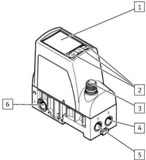
1 Display
2 Operating buttons Display menu
3 Plug M12
4 Working air port (2)
5 Exhaust air port (3)
6 Compressed air port (1)
Fig. 1: Product design
4.2 Function
A built-in pressure sensor records the pressure at the working port and compares this value with the setpoint value. In the event of deviations between the setpoint value and actual value, the valve regulates until the outlet pressure has reached the setpoint value.
| VPPI -...- 3 -...Working pressure (2) blocked, normally closed | VPPI -...- 4 -...Working pressure (2) is exhausted to the pressure at the exhaust pressure (3), normally open |
Tab. 4: Pneumatic circuit symbol
5 Assembly
5.1 Preparation
- Make sure there is sufficient space for the connecting cable and tubing connections.
-Place the valve as close to the consumer as possible.
-Remove the plug screw and sealant from the duct (1).
5.2 Assembling
5.2.1 Creating pressure zones
i
For separating pressure zones, connect the compressed air supply to both ends of the valve manifold.
For pressure zone separation, the plug screw can be left in duct (1) of the valve. Plug screws for duct (1) can also be ordered as accessories (VAME-P18-BP-G18-P5) → www.festo.com/catalogue.
- Screw the plug screw into the duct (1) of the selected valve. Screw in the plug screw until it is flush with the surrounding surface.

natural_image
Technical line drawing of a mechanical device with ports and control panel (no text or symbols)5.2.2 Linkage of valves
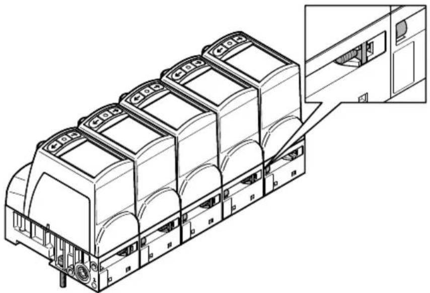
Up to 5 valves can be linked. The connecting kit VAME-P18-K-P5 is required for linking
→ www.festo.com/catalogue.
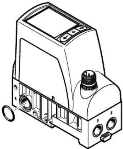
The connecting kit consists of 2 square nuts, 2 socket head screws and an O-ring.
-
Remove the plug screw and sealing material from the duct (1).
-
Insert the O-ring into the duct (1) between 2 valves.
natural_image
Technical line drawing of a mechanical device with ports and control panel (no text or symbols)Assembly
- Connect the valves on the underside using socket head screws and square nuts. Tightening torque: 1.2 ± 0.2 Nm

natural_image
Technical line drawing of a mechanical component with internal cavities and mounting holes (no text or symbols)- Connect valves at the rear using socket head screws and square nuts. Tightening torque: 1.2 ± 0.2 Nm
natural_image
Technical line drawing of a multi-level industrial machine or storage unit with internal components, showing structural details and mounting brackets (no text or symbols present)5.3 Mounting
5.3.1 Mounting via bottom of valve
natural_image
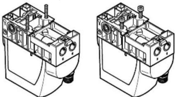
Technical line drawings of two mechanical components with internal cavities and mounting holes (no text or symbols)Fig. 2: Mounting via bottom of valve with M4 screws/M4 screws and square nuts
Installation
5.3.2 Mounting via valve side surface

natural_image
Technical line drawing of a mechanical device housing with internal components (no text or symbols)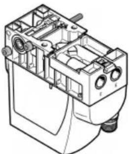
natural_image
Technical line drawing of a mechanical device with internal components and mounting holes (no text or symbols)Fig. 3: Mounting via side with internal M4 screws/M4 through screws
5.3.3 Mounting on H-rail

natural_image
Technical line drawing of a mechanical device with internal components and mounting holes (no text or symbols)Fig. 4: Individual valve
5.4 Fitting
6 Installation
6.1 Installation, pneumatic
Valves for standard operation
- Attach the tubing to the ports:
-Compressed air (1)
- Working air (2)
- Fit a silencer at the exhaust pressure (3) or install ducted exhaust air.
Valves VPPI-...-1V...H-... for vacuum operation or combined vacuum and standard operation
-
Attach the tubing to the ports:
-
Vacuum (3)
-
Working air (2)
-
Connect a compressed air supply to port (1) or mount a silencer to protect the valve from coarse dirt particles.
6.2 Electrical installation

WARNING
Risk of injury due to electric shock.
- For the electric power supply, use SELV or PELV circuits that guarantee a reliable electric disconnection from the mains network.
-
Observe IEC 60204-1/EN 60204-1.
-
If a screened cable is used: earth the screen at the cable end away from the valve.
- Do not crush, kink or stretch electrical connecting cables during installation.
- Tighten the electrical connecting cable on the M12 plug. Tightening torque: maximum 0.3 Nm
| Connection Pin Assignment Wire colour | 1)(NEBU-M12...) | |||
 | 1 + 24 V DC + 24 V DC BN | |||
| 2 Setpoint value (-) DI1 WH | ||||
| 3 GND GND BU | ||||
| 4 Setpoint value (+)/PWM DIO BK | ||||
| 5 Actual value output- based on pin 2 "set-point value (-)" for type VPPI-...-V...- based on pin 3 "GND" for VPPI-...-A... | DI2 GY | |||
1) Colour code in accordance with IEC 60757:1983-01
Tab. 5: Pin allocation for M12 plug, 5-pin
7 Commissioning
Requirements:
-The valve is mounted.
- The pneumatic and electrical installation is complete and tested.
- Check operating conditions and critical limits 11 Technical data.
- Switch on the power supply.
- Switch on the compressed air supply.
- Parameterise valve.
8 Parameterisation
The valve can be parameterised in the display menu using the 3 operating buttons.
8.1 Function of the Operating Buttons
The basic functions of the operating buttons are:
Press Middle Button:
- Navigate one menu level deeper.
- Accept edited value.
Hold Middle Button for 3 s (or No Button Press for More than 60 s):
- From any menu level back to the start screen (if a value is currently being edited, it is not accepted).
Press Left / Right Button:
- Navigate within a menu level.
Navigate to the Menu Item 'Exit' with the Left or Right Pushbutton and Confirm with the Middle Pushbutton:
- Navigate one menu level higher.
8.2 Menu Levels

flowchart
graph TD
    A["Input"] --> B["Exit"]
    B --> C["Input max 9.500 V"]
    C --> D["Edit Parameter Input max 9.500 V"]
    D --> E["Output"]
    F["VFP1 Small mode Pressure (kW) 4.580 Setpoint: 4.61"] --> G["Menu"]
    G --> H["Input"]
    H --> I["Set"]
    I --> J["Menu"]
    J --> K["Exit"]
    K --> L["Output"]
    M["Edit Parameter Input type Analog"] --> N["Input type Digital"]
    N --> O["Output"]
    P["Edit Parameter Input type Analog"] --> Q["Output"]
    Q --> R["Output"]
    S["Input"] --> T["Set"]
    T --> U["Input"]
    U --> V["Set"]
    V --> W["Input"]
    X["Input"] --> Y["Set"]
    Y --> Z["Input"]
    Z --> AA["Set"]
    AA --> AB["Input"]
    AC["Input"] --> AD["Set"]
    AD --> AE["Input"]
    AE --> AF["Set"]
    AF --> AG["Input"]
Fig. 5: Menu levels (excerpt)
8.3 Contents of the menu
Menu level 1 'Input'
| Menu option Content | Description | |
| ‘Input type’ ‘Analog’/‘Digital’ Appears only for voltage variants. ‘Input type’ = ‘Analog’ is for current variants.-‘Analog’: an analogue voltage/current value via setpoint value (+) and setpoint value (-) determines the setpoint pressure.-‘Digital’: one of 8 setpoint values is specified via three digital 24 V inputs. The three inputs are interpreted as a binary number with 3 bits.The allocation is as follows:- Setpoint value (+): DI0 or least significant bit-Setpoint value (-): DI1-Actual value output: DI2 or most significant bitThe value 000 means 0 bar and cannot be edited; the remaining 7 values can be set in ‘Input values’. There is no actual value output in this mode. | ||
| ‘Input unit’ [V/mA]/[bar/kPa/psi]/% | Appears only if ‘Input type’ = ‘Analog’.Determines the unit in which the setpoint value is displayed on the main screen. | |
| ‘Input max’ e.g. 5 V Appears only if ‘Input type’ = ‘Analog’.upper limit of the analogue setpoint value range | ||
| ‘Input min’ e.g. 0 V Appears only if ‘Input type’ = ‘Analog’.lower limit of the analogue setpoint value range | ||
| ‘Ramp-up-time’ ‘Off’/X msX=75/125/250/500/750/1000/1500/2000 | Setpoint jumps upwards are filtered with a low-pass filter. The set value is the time constant (tau) in milliseconds. | |
| ‘Ramp-down-time’ ‘Off’/X msX=75/125/250/500/750/1000/1500/2000‘Force input’ e.g. 50% | Setpoint jumps downwards are filtered with a low-pass filter. The set value is the time constant (tau) in milliseconds.Exception: with variants VPPI-...-...L...H-... exhausting to 0 bar is always run as quickly as possible. If deceleration is desired, the pressure must first be exhausted to a pressure of ≥ 1% FS.With this, a setpoint value between 0 ... 100 % of the parameterised pressure range can be specified directly via the menu. During this specification, the setpoint input is ignored. | |
| ‘Exit’ -- | ||
Tab. 6: "Input"
Menu level 1'Input values'
i
The ‘Input values’ menu option only appears if ‘Input type’ = ‘Digital’ has been selected.
| Menu option Content | Description | |
| ‘Value 001’ e.g. 6 bar | Setpoint value, if value of the digital inputs = 001 | |
| ‘Value 010’ e.g. 6 bar | Setpoint value, if value of the digital inputs = 010 | |
| ‘Value 011’ e.g. 6 bar | Setpoint value, if value of the digital inputs = 011 | |
| ‘Value 100’ e.g. 6 bar | Setpoint value, if value of the digital inputs = 100 | |
| ‘Value 101’ e.g. 6 bar | Setpoint value, if value of the digital inputs = 101 | |
| ‘Value 110’ e.g. 6 bar | Setpoint value, if value of the digital inputs = 110 | |
| ‘Value 111’ e.g. 6 bar | Setpoint value, if value of the digital inputs = 111 | |
| ‘Exit’ -- | ||
Tab. 7: "Input values"
i
One of 8 setpoint values is specified via three digital 24 V inputs. The three inputs are interpreted as a binary number with 3 bits.
The allocation is as follows:
- Setpoint value (+): DIO or least significant bit
- Setpoint value (-): D11
• Actual value output: D12 or most significant bit
The value 000 means 0 bar, the remaining 7 values can be set in 'Input values'.
Menu level 1'Output'
i
The 'Output' menu option only appears if 'Input type' = 'Analog' has been selected.
| Menu option Content | Description | |
| ‘Output type’ ‘Analog’/‘Digital’ Appears only for voltage variants. ‘Output type’ = ‘Analog’ is for current variants.-‘Analog’: the current actual pressure is output as an analogue voltage/current value via the actual value output.- ‘Digital’: a digital 24 V signal is output via the actual value output, which switches as soon as the actual value is within the parameterised limits. | ||
| ‘Output max’ e.g. 5 V Appears only if ‘Output type’ = ‘Analog’.Upper limit of the electrical actual value output in analogue mode | ||
| ‘Output min’ e.g. 0 V Appears only if ‘Output type’ = ‘Analog’.Lower limit of the electrical actual value output in analogue mode | ||
| ‘Digital out’ ‘High OK’/‘Low OK’ Appears only if ‘Input type’ = ‘Digital’.Switchover of the meaning of high or low signal at the digital output:-‘High OK’: High is output if the actual value lies within the parameterised limits.-‘Low OK’: Low is output if the actual value lies within the parameterised limits. | ||
| ‘Hysteresis +/-’ e.g. 0.200 bar Appears only if ‘Input type’ = ‘Digital’Setting of the limits for the digital output. The set value corresponds to the maximum deviation from the setpoint value, which is evaluated as OK for the digital output. | ||
| ‘Output delay’ e.g. 100 ms Appears only if ‘Input type’ = ‘Digital’Delayed output of edge changes at the actual value output in order to filter short status changes (e.g. with setpoint value jumps). Shorter pulses than defined in ‘Output delay’ are not output. | ||
| ‘Exit’- | - | |
Tab. 8: "Output"
Menu level 1'Pressure'
| Menu option Content | Description | |
| ‘Pressure unit’ bar/kPa/psi Pressure unit in which all pressures are displayed. | ||
| ‘Pressure max’ e.g. 5 | bar Appears only if ‘Input type’ = ‘Analog’.Upper limit of the pressure regulation range | |
| ‘Pressure min’ e.g. 1 | bar Appears only if ‘Input type’ = ‘Analog’.Lower limit of the pressure regulation range | |
| ‘Exit’ -- | ||
Tab. 9: "Pressure"
Menu level 1'Parameters'
| Menu option Content | Description | |
| ‘Parameter set’ Setting | g of the control response | |
| ‘Small’ | - ‘Small’: default set for all applications. Optimised for closed volumes of 100 ml to approx. 750 ml. For larger volumes, ‘Small’ results in a softer con-trol response than ‘Large’. For applications with flow rate ‘Small’ is only suitable to a limited extent (< 100 l/min) | |
| ‘Large’ | - ‘Large’: optimised for closed volumes (≥ 750 ml on 1 m tubing, ∅ 8 mm). Faster regulation of pres-sure jumps. | |
| ‘Flow’ | - ‘Flow’: designed for flow rate applications. Softer control response due to greater hysteresis. Can also be used for closed volumes. | |
| ‘Custom’ | - ‘Custom’: individual adaptation to higher volumes or applications with longer/thinner tubing or con-strictions within the application. | |
| ‘Reference run’ ‘Start’ | Appears only if ‘Paramet er set’ = ‘Custom’ → Run-ning homing. | |
| ‘Tune pres incr’ e.g. 5 | 200 ‘Tuning pressure increase’ appears only if ‘Parameter set’ = ‘Custom’. Setting of the tuning parameter for pressure jumps upwards. | |
| ‘Tune pres decr’ e.g. | 5600 ‘Tuning pressure decrease’ appears only if ‘Parameter set’ = ‘Custom’.Setting of the tuning parameter for pressure jumps downwards. | |
| ‘Exit’ -- | ||
If the ‘Custom’ parameter set is selected, brief pressure rises up to the input pressure are possible at the working port. This is independent of any set limit values ('Pressure min'/'Pressure max'). The complete input pressure or the vacuum present at the exhaust port can be present at the working port during the regulation process and during homing.
If the application and the tuning parameters do not match, an uncontrolled response is possible (continuous oscillation, continuous maximum or minimum pressure at the working port). If the application is changed, the tuning parameters must be adjusted.
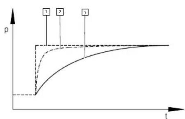
The ‘Custom’ parameter set permits individual adjustment/optimisation of the control response for an application. This adjustment enables greater pressure dynamics in the face of a constriction compared to a standard controller. This considerably reduces settling times for pressure jumps. The two required model parameters (‘Tuning increase’/‘Tuning decrease’) can be determined automatically via homing. The determined model parameters can also be adjusted manually at the port at any time. Free input of the two model parameters without homing is also possible.
line
| t | p (Line 1) | p (Line 2) | p (Line 3) | | ---- | ---------- | ---------- | ---------- | | Low | Low | Low | Low | | Mid | High | Medium | Low | | High | High | High | Medium |Fig. 6: Pressure jump in standard controller (basic representation)
1 Target pressure
2 Valve pressure at the working port
3 Pressure in the working volume
Parameterisation

line
| t | p | | ---- | ----- | | 0 | 0 | | 0.5 | Low | | 1 | Peak | | 2 | Peak | | 3 | Stable | | High | Stable | | Low | Low | | High | Stable |1 Target pressure
2 Valve pressure at the working port
3 Pressure in the working volume
Fig. 7: Pressure jump preset "Custom" (basic representation)
Running homing
- Connect application (connected volumes, tubing, air consumption and supply pressure must correspond to the working conditions).
- Activate 'Custom' parameter set.
- Select 'Reference run' menu option.
A warning appears.
- Confirm warning with the middle button.
- Use the arrow keys to change from the 'Cancel' menu option to the 'Start' menu option and confirm with the middle pushbutton.
Homing is started.
- Wait until 'Successful' or 'Failed' is displayed.
Homing typically takes 30 ... 40 s.
The ‘Successful’ result indicates that homing has automatically determined tuning parameters. The ‘Failed’ result indicates that homing has failed.
Possible causes of a failed homing ('Failed'):
-Lack of supply pressure (working pressure does not reach 'Pressure max'.)
-application too fast (no bottleneck)
- extremely slow application (very large volume, very long tubing)
In these cases, the ‘Custom’ parameter set can be used by manually entering the ‘Tune pres incr’/‘Tune pres decr’ parameters.
i
Manual adjustment/free input of the tuning parameters:
The physical meaning of ‘Tune pres incr’/‘Tune pres decr’ corresponds to that of a master value for the pressurisation or exhaust process. If the tuning parameter is increased, the control response is softened. If the tuning parameter is reduced, the control response becomes more aggressive.
Menu level 1'Display'
| Menu option Content | Description | |
| ‘Pin code’ 0000 ... 99 | 99 Protect device against | accidental parameter changes.Pin 0000 switches off pin sensing. |
| ‘Sleep timeout’ ‘Off’/X s, X minX=5/10/20/40 s1/3/5 min | X s, X minX=5/10/20/40 s1/3/5 min | Deactivation/activation of sleep mode.If there is no key input in the set time, the valve switches from the main screen to sleep mode, whereby reduced information is displayed on a dark-ened screen. This setting has no influence on the pressure regulation function. |
| ‘Rotate’ ‘Off’/90°/180°/-90° Rotates the entire | Rotates the entire | display on the screen for operation when the installation is rotated. |
| ‘Graph’ ‘Accuracy Graph’/‘Full-scale Graph’ | ‘Full-scale Graph’ | Displays a deviation graph or a full-scale graph on the main screen. |
| ‘Main value’ ‘Pressure’/‘Setpoint’ Highlights either the actual value or the setpoint value on the main screen. | either the actual value or the setpoint value on the main screen. | |
| ‘Exit’-- | ||
Tab. 11: "Display"
9 Malfunctions
9.1 Diagnostics
| Error text in the display | Fault description | Remedy |
| ‘Overheat’ | Working temperature is too high. Valve is in temperature shut-off. | Switch off the valve, let it cool down and restart. Reduce ambient temperature or temperature of medium. |
| ‘Cable break’ | Cable break setpoint input | Check connection to setpoint generator.Replace electrical connecting cable. |
| ‘Oscillation’ | Continuous vibration detected. | Select another parameter set for application. |
| ‘No air supply’ | No input pressure p1.Setpoint value not reached. | Increase input pressure p1.Maintain permissible maximum operating pressure → 11 Technical data. |
| ‘DC-supply low’ | Supply voltage is too low. | Increase supply voltage. |
| Error text in the display Fault description Remedy | ||
| ‘DC-supply high’ Supply voltage is too high. Reduce supply voltage. | ||
| ‘Heat protection’ Temperature critical, power reduction active. | Reduce ambient temperature or temperature of medium. Ensure sufficient compressed air supply. | |
| ‘High deviation’ Setpoint value not reached.Input pressure p1 is too low.Air consumption at the working port is too high. | Increase input pressure p1.Maintain permissible maximum operating pressure → 11 Tech-nical data. | |
| ‘Setpoint high’ Analogue setpoint value is too high. | Correct setpoint value. |
Tab. 12: Error text in the display
9.2 Fault clearance
| Fault description Cause Remedy | ||
| Valve does not respond. Operating | voltage not applied. Check the operation voltage connection. | |
| No setpoint voltage. Check the controller and connection. | ||
| Working temperature is too high. Valve is in temperature shut-off. | Switch off the valve, let it cool down and restart. Reduce ambient temperature and / or temperature of medium. | |
| Valve normally open: The working pressure at (2) falls to the level at (3) (ambient pressure or vacuum). | Cable break setpoint input Check connection to setpoint generator. Replace electrical connecting cable. | |
| Valve normally closed: The working pressure at (2) deviates upwards or downwards from the setpoint value (working pressure is neither pressurised nor exhausted). | Cable break setpoint input Check connection to setpoint generator. Replace electrical connecting cable. | |
| Setpoint value not reached. Input | pressure at (1) is too low. Increase input pressure at (1). Maintain permissible maximum operating pressure → 11 Technical data. | |
Tab. 13: Fault clearance
10 Disassembly
- Specify setpoint value 0 bar (0 MPa).
- Switch off compressed air supply.
- Switch off operating voltage.
- Remove electrical connecting cables.
- Remove compressed air lines.
- Dismantle the product.
11 Technical data
11.1 Technical data, general
VPPI-...-A4/V1-S1
| Certificates, declaration of conformity | → www.festo.com/sp |
| Valve function 3-way proportional-pressure regulator | |
| Mounting position Any | |
| Product weight [g] 370 | |
| Ambient temperature [°C] 0 ...+ 50 | |
| Storage temperature [°C] -20 ... +70 | |
| Temperature of medium [°C] 0 ...+ 50 | |
| Degree of protection IP65 | Not applicable to UL |
| Operating medium Compressed air to ISO | 8573-1:2010 [7:4:4] |
| Inert gases | |
| Information on the operating medium | Lubricated operation not possible |
| Climate class in accordance with EN 60721 | 3k3 |
| Nominal operating altitude < 3000 m above MSL | |
| Materials | |
| Seals | HNBR |
| Housing | PA-reinforced |
Tab. 14: Technical data, general
Vibration resistance/shock resistance (in accordance with IEC 60068)
| Vibration resistance in accordance with IEC 60068-2-6 | Single valve mounted with screws: SL2 |
| Single valve mounted on H-rail: SG1 | |
| Linkage of a maximum of 3 valves: SG2 | |
| Linkage of a maximum of 5 valves: SG1 | |
| Shock resistance in accordance with IEC 60068-2-27 | Single valve mounted with screws: SL2 |
| Single valve on H-rail: SL1 | |
| Linkage of a maximum of 3 valves with side screw mounting: SG2 | |
| Linkage of a maximum of 5 valves with side screw mounting: SG1 |
Tab. 15: Operating conditions and ambient conditions
| Type of severity level (SL) | |||||
| Vibration load | |||||
| Frequency range [Hz] Acceleration | [m/s 2] Deflection [mm] | ||||
| SL1 SL2 SL1 SG2 | SL1 SL2 | ||||
| 2 ... 8 | 2 ... 8 | - | - | ±3.5 | ±3.5 |
| 8 ... 27 8 ... 27 | 10 10 -- | ||||
| 27 ... 58 | 27 ... 60 | - | - | ±0.15 | ±0.35 |
| 58 ... 160 60 ... | 160 20 50 -- | ||||
| 160 ... 200 160 | ... 200 10 10 -- | ||||
| Shock load | |||||
| Acceleration [m/s2] Duration [ms] | Shocks per direction | ||||
| SL1 SL2 SL1 SL2 | SL1 SL2 | ||||
| ±150 | ±300 | 11 | 11 | 5 | 5 |
| Continuous shock load | |||||
| Acceleration [m/s2] Duration [ms] | Shocks per direction | ||||
| ±150 | 6 | 1000 | |||
Tab. 16: Type of severity level (SL)
Cable break detection
Values for 'Input min' > 500 mV or > 2 mA activate the internal sensors for cable break detection. The sensor detects a cable break at voltages of < 500 mV or at currents of < 2 mA.
Cable break detection
| Valve variant Default value | ‘Input min’, adjustable | Cable break detection |
| VPPI-...-A4-... < 2 mA Cable | le break detection inactive. | |
| ≥ 2 mA Cable break detection active. At analogue input values below 2 mA the ‘Cable break’ error is displayed and the valve moves to the normal position. | ||
| VPPI-...-V1-... < 500 mV Cable | Cable break detection inactive. | |
| ≥ 500 mV Cable break detection active. At analogue input values below 500 mV the ‘Cable break’ error is displayed and the valve moves to the normal position. | ||
Tab. 17: Cable break detection
Zero point suppression
| Valve variant ‘Pressure min’ menu setting | Response with < 0.7% Full scale setpoint value |
| VPPI-...-...L...H-... 0 MPa Exhaust to 0 bar and keep the exhaust open. | |
| > 0 MPa Active control on ‘Pressure min’. | |
| VPPI-...-1V1H-... -0.1 MPa Valve moves to normal position. | |
| > -0.1 MPA Active control on ‘Pressure min’. | |
| VPPI-...-1V0H-... – Active control on ‘Pressure max’. | |
Tab. 18: Zero point suppression
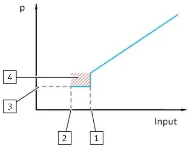
Setpoint values < 0.7% Full scale above the minimum input value ('Input min') are interpreted as the lowest input value in order to suppress noise at the input signal → Fig. 8. Depending on the valve variant and the minimum input pressure, there may be a special response in this area → Tab. 18 Zero point suppression.
Technical data
line
| Input | p | |-------|----| | 1 | 3 | | 2 | 4 |1 Minimum input value + 0.7% FS
2 Minimum input value
3 Minimum pressure/vacuum
4 Zero point suppression
Fig. 8: Zero point suppression
other
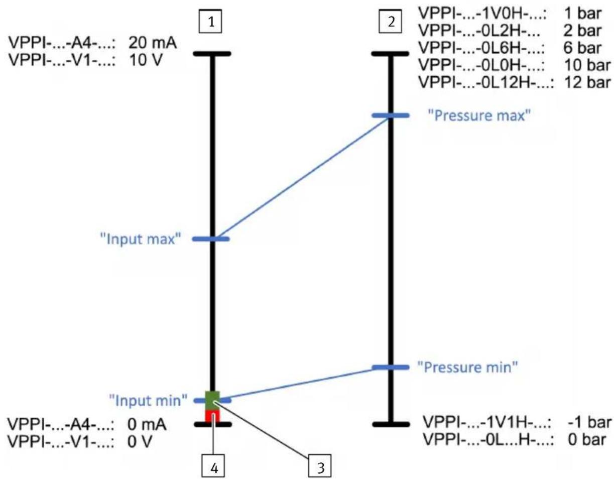
| Node | Voltage (mA) | Pressure (bar) | |------|--------------|----------------| | 1 | 20 | 1 | | 2 | -1 | 2 | | 3 | -1 | 0 | | 4 | 0 | -1 | | 5 | -1 | 0 | | 6 | -1 | 6 | | 7 | -1 | 10 | | 8 | -1 | 12 | The diagram includes a central node labeled 'Input min' and three vertical lines labeled 'Pressure min' and 'Pressure max'.Fig. 9: Valve variants for excess pressure and vacuum/excess pressure
1 Analogue setpoint value
2 Target pressure
3 Zero shutdown
4 Cable break

flowchart
graph TD
    A["VPPI-...-A4-: 20 mA\nVPPI-...-V1-: 10 V"] --> B["Input max"]
    C["VPPI-...-A4-: 0 mA\nVPPI-...-V1-: 0 V"] --> D["Input min"]
    B --> E["Pressure max"]
    D --> F["Pressure min"]
    E --> G["VPPI-...-1V0H-: 0 bar"]
    F --> H["VPPI-...-1V0H-: -1 bar"]
Fig. 10: Valve variants for vacuum
1 Analogue setpoint value
3 Cable break
2 Target pressure
Closed-loop systems characteristics ^1)
| Linearity 0.9% FS (full scale) | |
| Hysteresis 0.4% FS | |
| Reproducibility 0.4% FS | |
| Total accuracy 1.1% FS | |
| Temperature coefficient 0.02/K |
1) Maximum deviation, characteristic values determined at room temperature in accordance with ISO 10094. Linearity refers to the ideal characteristic curve.
Tab. 19: Closed-loop systems characteristics
11.2 Technical data, pneumatic
| VPPI-...- 1V0H | 1) | 1V1H 0L2H 0L6H 0L10H 0L12H | |||||
| Input pressure at (1) ^2) | [MPa] | 0 ... 0.6 | 0 ... 0.6 | 0 ... 0.6 | 0 ... 1.3 | 0 ... 1.3 | 0 ... 1.3 |
| [bar] | 0 ... 6 | 0 ... 6 | 0 ... 6 | 0 ... 13 | 0 ... 13 | 0 ... 13 | |
| Operating pressure at (1) ^3) | [MPa] | 0 ... 0.2 | 0.1 ... 0.2 | 0.2 ... 0.4 | 0.6 ... 0.8 | 1.0 ... 1.2 | 1.2 ... 1.3 |
| [bar] | 0 ... 2 | 1 ... 2 | 2 ... 4 | 6 ... 8 | 10 ... 12 | 12 ... 13 | |
| Input pressure at (3) Vacuum | [MPa] | -0.1 ... 0 | -0.1 ... 0 | ---- | |||
| [bar] | -1 ... 0 | -1 ... 0 | |||||
| Operating pressure at (3) | [MPa] | -0.1 ... 0 | -0.1 ... 0 | ---- | |||
| [bar] | -1 ... 0 | -1 ... 0 | |||||
| Pressure regulation range ^4) on (2) | [MPa] | -0.1 ... 0 | -0.1 ... +0.1 | 0 ... 0.2 | 0 ... 0.6 | 0 ... 1.0 | 0 ... 1.2 |
| [bar] | -1 ... 0 | -1 ... +1 | 0 ... 2 | 0 ... 6 | 0 ... 10 | 0 ... 12 | |
1) For variants VPPI-...-1VOH-... 0% corresponds to setpoint value 0 bar and 100% to setpoint value -1 bar.
2) The valve can be operated at an input pressure within the specified range. It must be noted here that the specified control quality is only fulfilled with a permanent supply within the operating pressure range and that the control pressure can reach the maximum available input pressure.
3) The specified control quality is only achieved if there is a permanent operating pressure supply at the valve within the specified range.
4) Active regulation is only from a setpoint value of 1% FS, below which the valve is at zero point suppression.
Tab. 20: Technical data, pneumatic
11.3 Technical data, electrical
| VPPI-...-S1 -A4 -V1 | |||
| Nominal operating voltage [V DC] 24 | |||
| Operating voltage range [V DC] 21.6 ... 27.6 | |||
| Nominal current [mA] 150 | |||
| Max. current consumption [mA] ≤ 525 | |||
| Max. permissible signal line length [m] | 30 | ||
| Setpoint input | |||
| Setpoint value input | [V DC]– | 0 ... 10 | |
| [mA] 4 ... 20 | – | ||
| Input voltage PWM/digital inputs | [V DC]– | 24 | Type 1 in accordance with DIN EN 61131 |
| PWM frequency | [Hz]– | 200 ... 800 | |
| PWM duty cycle | [%] | – | 20 ... 100 |
| VPPI-...-S1 -A4 -V1 | ||
| Input resistance [kΩ] – 100 | ||
| [kΩ] 0.3 – | ||
| Actual value output | ||
| Max. output current [mA] 25 | ||
| Analogue output [V DC] – 0 ... 10 | ||
| [mA] 4 ... 20 – | ||
Tab. 21: Technical data, electrical
11.4 Technical data for UL certification
| VPPI | ||
| Installation site For indoor use only. | Suitable for use in moist environments. | |
| Pollution degree 2 | ||
| Relative humidity | [%] | 0 ... 85 |
| Maximum fluid temperature/ambient | [°C] | 0 ... +50 |
| [°F] | 32 ... +122 | |
| Operating voltage range | [V DC] | 21.6 ... 27.6 |
| Max. current consumption | [mA] | 525 |
| Max. installation height | [m] | 3000 |
| Overvoltage category | II | |
| Protection class | III SELV/PELV | |
Tab. 22: Technical data UL
Copyright:
Festo SE & Co. KG
Ruiter Straße 82
73734 Esslingen
Germany
Phone:
+49 711 347-0



- FESTO
- Table of contents
- About this document.... 4
- Safety....4
- Additional information....5
- Product overview....6
- Assembly....6
- Installation....9
- Commissioning.... 10
- Parameterisation.... 10
- Malfunctions....18
- Disassembly.... 20
- Technical data....20
- About this document
- Applicable documents
- Product labelling
- Safety
- Safety instructions
- Intended use
- Training of qualified personnel
- UL approvals
- Additional information
- Product overview
- Product design
- Function
- Assembly
- Preparation
- Assembling
- Creating pressure zones
- Linkage of valves
- Assembly
- Mounting
- Mounting via valve side surface
- Mounting on H-rail
- Fitting
- Installation
- Installation, pneumatic
- Valves for standard operation
- Valves VPPI-...-1V...H-... for vacuum operation or combined vacuum and standard operation
- Electrical installation
- WARNING
- Risk of injury due to electric shock.
- Commissioning
- Parameterisation
- Function of the Operating Buttons
- Press Middle Button:
- Press Left / Right Button:
- Menu Levels
- Contents of the menu
- Menu level 1'Input values'
- Menu level 1'Output'
- Parameterisation
- Running homing
- Possible causes of a failed homing ('Failed'):
- i
- Malfunctions
- Fault clearance
- Disassembly
- Technical data
- Technical data, general
- Cable break detection
- Technical data
- Technical data for UL certification
Brand : Festo
Model : VPPI
Category : Pressure regulator