
VAVE-P17-TP-5YL1-P - Electronic module Festo - Free user manual and instructions
Find the device manual for free VAVE-P17-TP-5YL1-P Festo in PDF.


| Product Type | Valve Terminal |
| Manufacturer | Festo |
| Model | VAVE-P17-TP-5YL1-P |
| Number of Valves | 8 (max) |
| Valve Function | 2x 3/2-way or 4/2-way |
| Operating Pressure | 2 to 8 bar |
| Pilot Pressure | 3 to 8 bar |
| Fluid | Compressed air, filtered and unlubricated |
| Temperature Range | -5°C to +50°C |
| Protection Class | IP65 |
| Electrical Connection | Fieldbus (optional) or multi-pin |
| Manual Override | Yes |
| LED Indication | Yes |
| Dimensions (W x H x D) | 80 x 40 x 60 mm |
| Weight | Approx. 0.5 kg |
| Material | Aluminium alloy, plastic |
| Mounting | On manifold plate or directly |
| Maintenance | Replace seals every 10 million cycles |
| Certifications | CE, RoHS |
| Accessories | Mounting kit, silencers |
Frequently Asked Questions - VAVE-P17-TP-5YL1-P Festo
User questions about VAVE-P17-TP-5YL1-P Festo
0 question about this device. Answer the ones you know or ask your own.
Ask a new question about this device
Download the instructions for your Electronic module in PDF format for free! Find your manual VAVE-P17-TP-5YL1-P - Festo and take your electronic device back in hand. On this page are published all the documents necessary for the use of your device. VAVE-P17-TP-5YL1-P by Festo.
USER MANUAL VAVE-P17-TP-5YL1-P Festo
VAVE-P...-TP Electronics modul
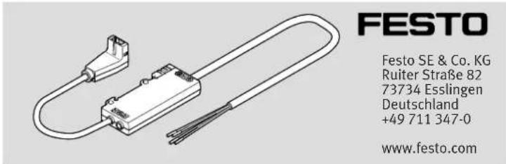
Operating instructions
8154158
2021-03a
[8154160]

8154158
Translation of the original instructions
© 2021 all rights reserved to Festo SE & Co. KG
1 About this document
1.1 Applicable documents
[Unreadable]
All available documents for the product→ www.festo.com/sp.
| Document Product Table of contents | |
| Operating instructions Piezo valve VEMP-BS-3 – | |
| Operating instructions Piezo valve VEAE-BB-6-...-X4 – |
Tab. 1: Applicable documents
1.2 Product labelling
Warning symbols on the product
| If the housing is damaged, protection against dangerous voltages is no longer guaranteed. | |
| Dangerous voltages up to 310 V are generated during operation. |
Tab. 2: Meaning of the warning symbols
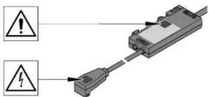
Fig. 1: Position of the warning symbols
2 Safety
2.1 Safety instructions
- Only use the product in original status without unauthorised modifications.
-Only use the product if it is in perfect technical condition. - Provide suitable protective measures against impact loads.
-Do not subject the product to mechanical stress.
-Take into consideration the ambient conditions at the location of use. - Before working on the product, switch off the power supply and secure it against being switched on again.
- Do not damage product labels and warning symbols.
2.2 Intended use
The electronics module is intended for the control and power supply of Festo piezo valves.
| Electronics module with electrical plug-in base | for piezo valve | |
| VAVE-P12-TP-5YL1-P - VEMP | ||
| NEFV-V13-XX4G3-T1G3 VEMR | ||
| NEFV-V14-XX4G3-T1G3 VEAE | ||
| VAVE-P17-TP-5YL1-P - VEMC | ||
Tab. 3: Use of the electronics module
2.3 Training of qualified personnel
Work on the product may only be carried out by qualified personnel who can evaluate the work and detect dangers. The qualified personnel have skills and experience in dealing with electrical (open-loop) control technology.
3 Additional information
- Contact the regional Festo contact if you have technical problems
→ www.festo.com.
-Accessories → www.festo.com/catalogue.
4 Product range overview
4.1 Scope of delivery

natural_image
3D mechanical component diagram showing a U-shaped connector with attached wires and a labeled connection point (no text or symbols present)Fig.2
1 Electronics module (1x) VAVE-P...-TP
4.2 Not in scope of delivery

Fig.3
2 Piezo valve (1x) VEMP
3 Piezo valve (1x ... 2x) VEMR
4 Piezo valve (1x ... 2x) VEAE
5 Piezo valve (1x) VEMC
6 Electrical plug-in base (1x) NEFV-V13-XX4G3-T1G3
(for piezo valves VEMR)
7 Electrical plug-in base (1x)
NEFV-V14-XX4G3-T1G3
(for piezo valves VEAE)

natural_image
Pure technical line drawing of a metal bracket with a numbered connection point (no text or symbols)Fig.4
8 H-rail (1x) 60715 TH35-...
4.3 Function
The electronics module is a two-channel, unregulated piezo controller with integrated high-voltage generation for piezo valves.
5 Transport and storage
- Store the product in a cool, dry environment protected from UV and corrosion. Keep storage times short.
6 Assembly
6.1 Combination of VAVE-P12-TP with piezo valve VEMP
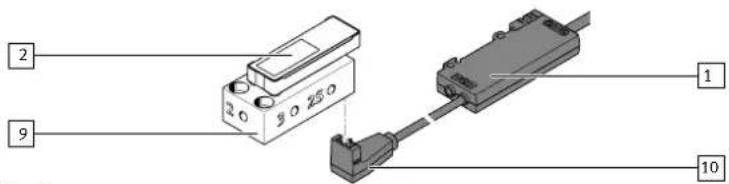
Fig.5
1 Electronics module
2 Piezo valve
9 Sub-base
10 Socket
- Mount the piezo valve on the sub-base → 1.1 Applicable documents.
- Push the piezo valve plug into the socket to the stop.
- Lock socket to prevent loosening.
6.2 Combination of VAVE-P12-TP with piezo valve VEMR

Fig.6


- Select screw suitable for the installation situation. Screw size: M3
- Mount the electrical plug-in base on the mounting surface using the screw. Tightening torque: 0.5 Nm ± 5%
- Push the socket onto the plug of the electrical plug-in base.
- Lock socket to prevent loosening.
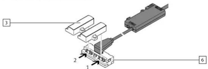
Fig.7


- Note the position of piezo valve slots 1 and 2 on the electrical plug-in base.
- Insert the flex conductor of the piezo valves into the electrical plug-in base.
6.3 Combination of VAVE-P12-TP with piezo valve VEAE

Fig.8
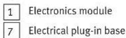

- Select screw suitable for the installation situation. Screw size: M3
- Mount the electrical plug-in base on the mounting surface using the screw. Tightening torque: 0.5 Nm ± 5%
- Push the socket onto the plug of the electrical plug-in base.
- Lock socket to prevent loosening.

Fig.9


- Note the position of piezo valve slots 1 and 2 on the electrical plug-in base.
- Mount the piezo valves on the sub-bases 1.1 Applicable documents.
- Insert the flex conductor of the piezo valves into the electrical plug-in base.
6.4 Combination of VAVE-P17-TP with piezo valve VEMC

natural_image
Pure electrical connector diagram without any text, numbers, or symbolsFig.10
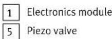
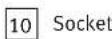
- Push the piezo valve plug into the socket to the stop.
- Lock socket to prevent loosening.
7
Mounting
7.1 H-rail mounting

Fig.11
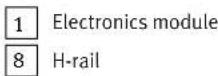

- Mount H-rail horizontally.
- Attach the electronics module to the top edge of the H-rail. The hook is located behind the upper edge of the H-rail.
- Press electronics module downwards.
- Swivel electronics module against the H-rail. Lug clips behind the lower edge of the H-rail.
7.2 Wall mounting

natural_image
Diagram of a mechanical component with labeled parts (1 and 15), no readable text or symbols beyond labelsFig.12


- Select screws suitable for the installation situation. Screw size: M3
- Mount the electronics module on the mounting surface with two screws. Tightening torque: 0.5 Nm ± 5%
8 Electrical installation

WARNING
Risk of Injury due to Electric Shock.
- For the electric power supply, use only PELV circuits that ensure a reliable electric disconnection from the mains network.
- Observe IEC 60204-1/EN 60204-1.
- The unit must be powered by a power source that fulfils the requirements of an energy-limited circuit in accordance with IEC 61010-1/EN 61010-1.

WARNING
Risk of injury due to electric shock.
If the housing is damaged, protection against dangerous voltage is no longer guaranteed.
- Do not start the device.
- Immediately shut down the device.
- Install electrical connecting cables without crushing, kinking or stretching them.
- Connect field device side.
| Socket | |||
| Pin Signal | |||
| VAVE-P12-TP VAVE-P17 | TP | ||
| 1 GND 0 ... | 310 V, channel 1 | ||
| 2 0 ... 310 | V, channel 1 GND | ||
| 3 0 ... 310 | V, channel 2 0 ... 310 V, | channel 2 | |
- Connect controller side.
Cable
| Wire ends Signal | ||
| BNWHBUBK | BN 12 ... 24 V DC, supply | |
| WH 0 ... 10 V DC, analogue2 | ||
| BU GND | ||
| BK 0 ... 10 V DC, analogue1 | ||
When it is switched off, the unit may generate an electrical impulse, which causes a short pressure pulse on the piezo valves.
9 Operation
WARNING
Danger of burns from hot housing surfaces.
The product does not have short circuit protection. The housing surface of the product can become hot in the event of a short circuit in the piezo valve.
• Before touching the housing surface, check the temperature.
10 Cleaning
- If necessary, clean the product with a dry, soft cloth without cleaning agents.
11 Technical data
VAVE-P...-TP
| Technical data, general | |||
| Mounting position | |||
| H-rail mounting horizontal | |||
| Wall mounting any | |||
| Degree of protection IP40 | |||
| Temperature range | |||
| Environment [°C] -10 ... +60 | |||
| Storage [°C] -40 ... +80 | |||
| Maximum operating height [m] 2000 | |||
| Ambient conditions | dry indoor environment → IEC 61010 | ||
| Technical data, electrical | |||
| Operating voltage range | [V DC] | 12 ... 24 | |
| Maximum input voltage | |||
| VEMP-...-22T1 | [V DC] | 8.06 | |
| VEMP-...-28T1 | [V DC] | 10.0 | |
| VEMC, VEAE, VEMR | [V DC] | 9.67 | |
| Maximum output voltage | |||
| VEMP-...-22T1 | [V DC] | 250 | |
| VEMP-...-28T1 | [V DC] | 310 | |
| VEMC, VEAE, VEMR | [V DC] | 300 | |
| Voltage fluctuations | [%] | ±10 | |
| Relative duty cycle | [%] | 100 | |
| Maximum switching frequency | |||
| 12 V operating voltage | [Hz] | 5 | |
| 24 V operating voltage | [Hz] | 10 | |
| Technical data, cable | Field device side | Controller side | |
| Cable composition | [mm2] | 2x0.25 + 1x0.14 | 4x0.25 |
| shielded | |||
| Cable diameter | [mm] | 3.4 | 4.5 |
| Cable sheath material | TPE-U (PUR) | PVC | |
| Cable bending radius | |||
| fixed cable installation | [mm] | 10.2 | 13.5 |
| flexible cable installation | [mm] | 34 | 45 |
Tab. 4: Technical data
- VAVE-P...-TP Electronics modul
- About this document
- Applicable documents
- Product labelling
- Safety
- Safety instructions
- Intended use
- Training of qualified personnel
- Additional information
- Product range overview
- Scope of delivery
- Not in scope of delivery
- Function
- Transport and storage
- Assembly
- Combination of VAVE-P12-TP with piezo valve VEMP
- Combination of VAVE-P12-TP with piezo valve VEMR
- Combination of VAVE-P12-TP with piezo valve VEAE
- Combination of VAVE-P17-TP with piezo valve VEMC
- Electrical installation
- Risk of Injury due to Electric Shock.
- Operation
- WARNING
- Danger of burns from hot housing surfaces.
- Cleaning
- Technical data
Brand : Festo
Model : VAVE-P17-TP-5YL1-P
Category : Electronic module