
HD CTL 100 - Joystick Extron - Free user manual and instructions
Find the device manual for free HD CTL 100 Extron in PDF.


| Product Type | Joystick Controller |
| Model | HD CTL 100 |
| Brand | Extron |
| Connectivity Interface | USB (Mini-B), RS-232 via optional adapter |
| Joystick Type | Analog, 3-axis (pan, tilt, zoom) |
| Number of Button Controls | 8 programmable buttons |
| Dimensions (L x W x H) | 4.5 x 2.5 x 1.5 inches (114 x 64 x 38 mm) |
| Weight | 0.5 lb (227 g) |
| Power Supply | USB bus-powered (5V, 500mA) |
| Cable Length | 6 ft (1.8 m) USB cable attached |
| Compatible Software | Extron PCS, Global Scripter, or third-party applications |
| Supported Functions | Pan, tilt, zoom, focus, iris, preset recall |
| Mounting | Desktop or panel-mount (with optional kit) |
| Operating Temperature | 32 to 104 °F (0 to 40 °C) |
| Storage Temperature | -4 to 140 °F (-20 to 60 °C) |
| Relative Humidity | 10% to 90% non-condensing |
| Included Accessories | USB cable, quick start guide |
| Maintenance | Clean with soft, dry cloth; avoid liquids |
| Safety Certifications | CE, FCC Class A, RoHS |
| Repairability | Replaceable USB cable; no user-serviceable parts inside |
Frequently Asked Questions - HD CTL 100 Extron
User questions about HD CTL 100 Extron
0 question about this device. Answer the ones you know or ask your own.
Ask a new question about this device
Download the instructions for your Joystick in PDF format for free! Find your manual HD CTL 100 - Extron and take your electronic device back in hand. On this page are published all the documents necessary for the use of your device. HD CTL 100 by Extron.
USER MANUAL HD CTL 100 Extron
HD CTL 100 • Setup Guide with Microsoft Teams Rooms (MTR)
This is a supplementary setup guide for properly setting up the HD CTL 100 with Microsoft Teams Rooms (MTR) (formerly known as Skype Room Systems).
The Extron HD CTL 100 is a compact workspace controller designed for automatic display control in small meeting rooms and huddle spaces. It features an HDMI pass-through port that detects signal presence. When an active signal is connected to the HDMI input from the Microsoft Teams Rooms (MTR) device, the HD CTL 100 automatically turns on the display via CEC control. When no signal is detected, the HD CTL 100 powers off the display after a predetermined period.
The diagrams in this guide show how to set up using either a dedicated Microsoft SRS device or a touchscreen display attached to a Microsoft Teams Rooms PC.
For advanced room automation and integration with optional room occupancy sensors, or the control of display via RS-232 (or infrared) using the Configuration Program, reference the full HD CTL 100 Workspace Controller Setup Guide, available at www.extron.com.
NOTE: For more details about installation, configuration, and operation, see the HD CTL 100 User Guide, available at www.extron.com.
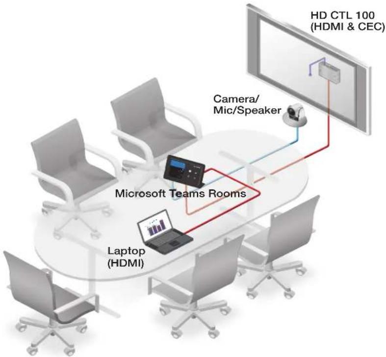
flowchart
graph TD
    A["Laptop (HDMI)"] --> B["Microsoft Teams Rooms"]
    B --> C["Camera/Mic/Speaker"]
    C --> D["HD CTL 100 (HDMI & CEC)"]
    style A fill:#f9f,stroke:#333
    style B fill:#ccf,stroke:#333
    style C fill:#cfc,stroke:#333
    style D fill:#fcc,stroke:#333
Example of Microsoft Teams Rooms (MTR)
HD CTL 100 Panels
The front and rear panel connectors include:
Rear Panel
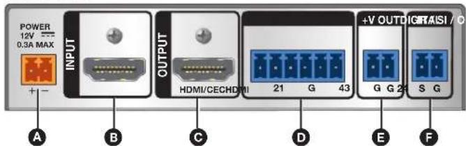
A Power input connector
B HDMI input connector
© HDMI/CEC output connector
Digital I/O ports
E Voltage output connector
F IR/S control connector
G Power LED
H Reset button
USB configuration port
J Signal LED
Front Panel
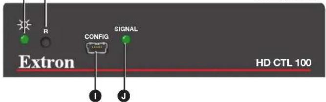
Figure 1. HD CTL 100 Rear and Front Panels
Connecting Microsoft Teams Rooms (MTR) to the HD CTL 100
The following are examples of Microsoft Teams Rooms devices that can be used with the HD CTL 100.
| Touchscreen Control with MTR Computer All-in-One MTR Computers | |
| Logitech® Tap• Lenovo | ® ThinksmartTM Hub 500 |
| HP® Elite Slice | Logitech SmartDock |
| Polycom® MSR Series | Polycom MSR Dock |
| Yealink® MVC Series | |
-
Connect the provided power supply to the device running MTR.
-
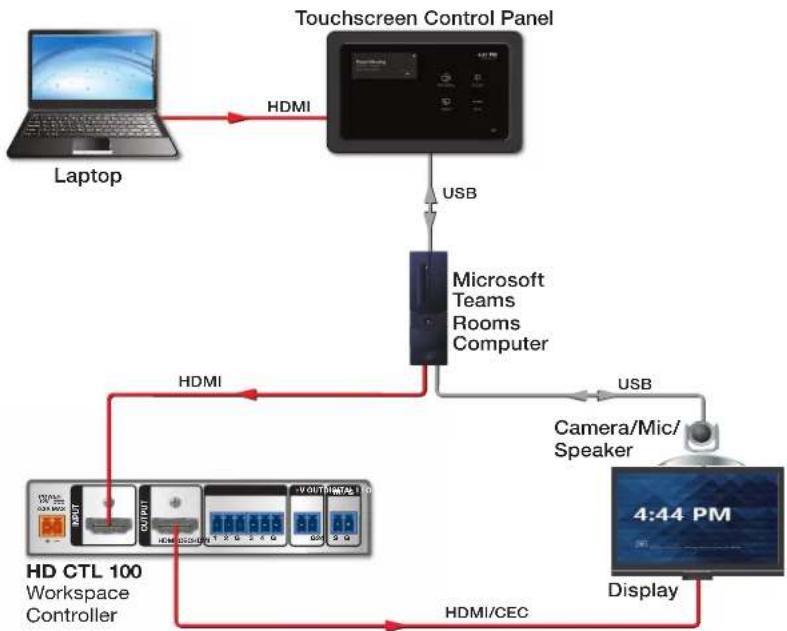
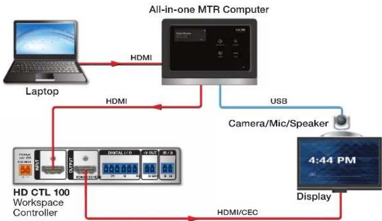
For a Single Display system, connect an HDMI cable from either of the MTR computer HDMI OUT connectors to the Input connector on the HD CTL 100 (see figure 2 and figure 3).
flowchart
graph TD
    A["Laptop"] -->|HDMI| B["Touchscreen Control Panel"]
    B -->|USB| C["Microsoft Teams Rooms Computer"]
    C -->|USB| D["Camera/Mic/Speaker"]
    D --> E["Display"]
    E -->|HDMI/CEC| F["HD CTL 100 Workspace Controller"]
    F -->|HDMI| G["User Interface"]
    G --> H["4:44 PM"]
Figure 2. Cabling Diagram (Single Display) for Touchscreen Control
flowchart
graph TD
    A["Laptop"] -->|HDMI| B["All-in-one MTR Computer"]
    B -->|USB| C["Display"]
    C -->|HDMI/CEC| D["HD CTL 100 Workspace Controller"]
    D -->|HDMI| B
    B -->|HDMI| E["Camera/Mic/Speaker"]
    E --> C
Figure 3. Cabling Diagram (Single Display) for MTR Computer
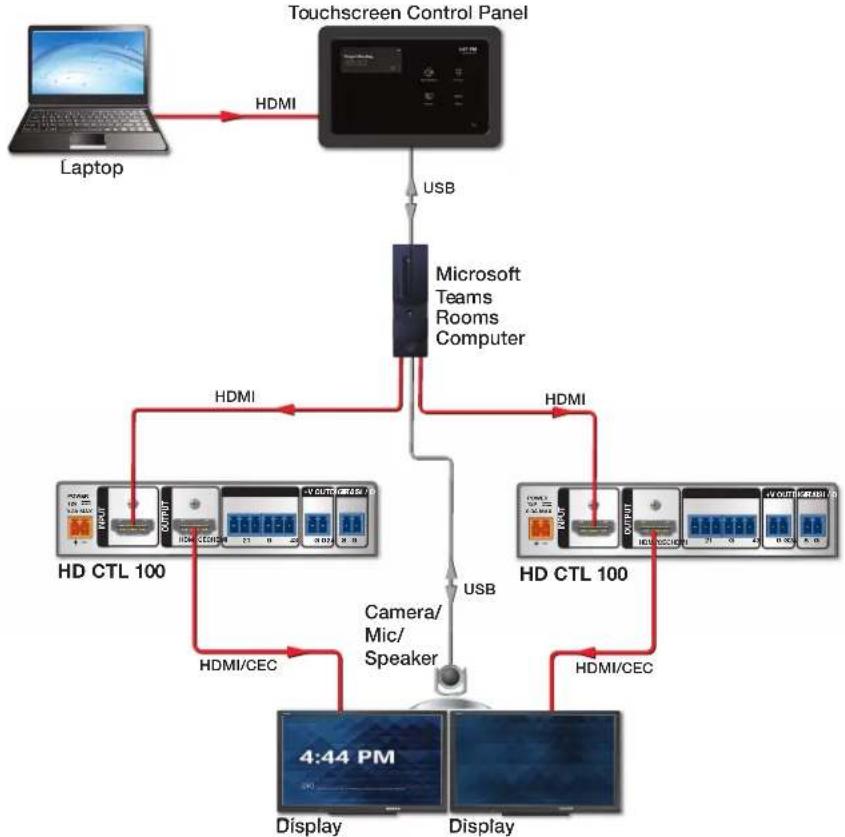
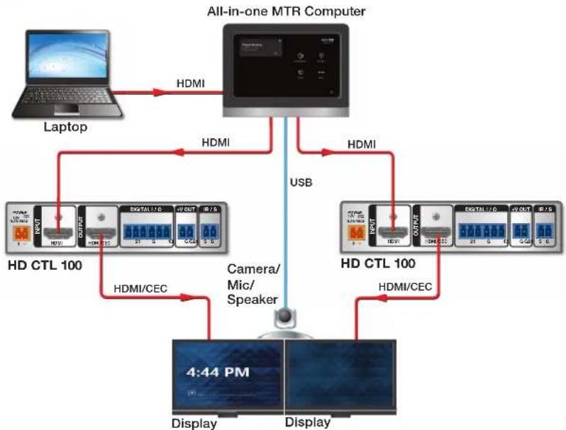
- For a Dual Display system, you need a second HD CTL 100. Connect HDMI cables from both of the MTR computer HDMI OUT connectors to the Input connectors of the two HD CTL 100s (see figure 4 and figure 5).
flowchart
graph TD
    A["Laptop"] -->|HDMI| B["Touchscreen Control Panel"]
    B -->|USB| C["Microsoft Teams Rooms Computer"]
    C -->|HDMI| D["HD CTL 100"]
    C -->|USB| E["HD CTL 100"]
    D -->|HDMI/CEC| F["4:44 PM Display"]
    E -->|HDMI/CEC| G["Display"]
    style A fill:#f9f,stroke:#333
    style B fill:#ccf,stroke:#333
    style C fill:#cfc,stroke:#333
    style D fill:#fcc,stroke:#333
    style E fill:#fcc,stroke:#333
    style F fill:#ffc,stroke:#333
    style G fill:#ffc,stroke:#333
Figure 4. Cabling Diagram (Dual Display) for Touchscreen Control
flowchart
graph TD
    A["Laptop"] -->|HDMI| B["All-in-one MTR Computer"]
    B -->|HDMI| C["USB"]
    C -->|HDMI| D["HD CTL 100"]
    D -->|HDMI/CEC| E["4:44 PM Display"]
    C -->|HDMI/CEC| F["HD CTL 100"]
    F -->|HDMI/CEC| G["Display"]
    D --> H["Camera/Mic/Speaker"]
    H --> I["Display"]
Figure 5. Cabling Diagram (Dual Display) for MTR Computer
NOTE: The displays in figure 2 on the previous page through figure 5 are controlled via CEC, which is accomplished using the same HDMI cables for transporting video from the Microsoft Teams Rooms to the display. For instances where the displays do not support CEC, use RS-232 or IR control. Enabling CEC on some displays may be required. Please consult the display manual for instructions
Microsoft Teams Rooms Setup Configuration
- With the MTR device powered up, at the main presentation window select the More icon (①).
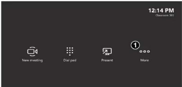
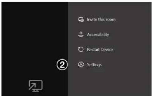
- Select Settings (②) and log in as administrator.
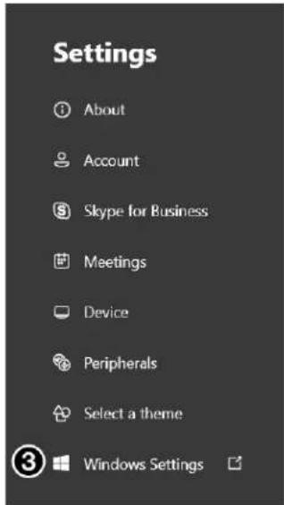
- Select Windows Settings (③) to go to the administrator sign-in.
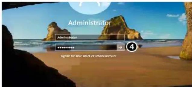
- On the Windows login page, select the appropriate user account to sign in as administrator and enter the credentials. Select the Right Arrow (4) when done.
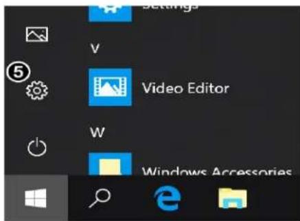
- From the Windows Start menu, select the Settings icon (⑤).
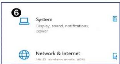
- Select System (⑥).
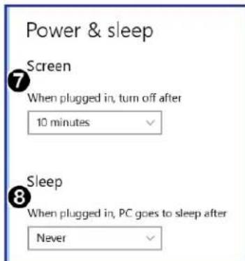
- To ensure the system turns off the presentation display when not in use, select Power and sleep on the System menu. The Screen time (⑦) for the display can be set to any specific value. The suggested Screen time, when on AC power, is 10 minutes. The suggested setting for Sleep (⑧) is Never.
- When motion is detected from the motion sensor on the MTR device, the video signal is given as an output to the HD CTL 100. The HD CTL 100 sends a power command to the display, and the MTR screen is then displayed on the display monitor.
NOTE: Plugging in a source device, such as a laptop, when the screen is in sleep mode does not wake the Microsoft Teams Rooms device.
For information on safety guidelines, regulatory compliances, EMI/EMF compatibility, accessibility, and related topics, see the Extron Safety and Regulatory Compliance Guide on the Extron website.
Brand : Extron
Model : HD CTL 100
Category : Joystick