
SEQ-8 - Séquenceur basse tension Lowell - Free user manual and instructions
Find the device manual for free SEQ-8 Lowell in PDF.


| Product Type | Sequencer / Controller |
| Brand | Lowell |
| Model | SEQ-8 |
| Dimensions (W x D x H) | 19 x 10 x 4 cm |
| Weight | 0.5 kg |
| Power Supply | 12V DC, 1A |
| Power Consumption | 12 W |
| Number of Channels | 8 |
| Main Functions | Sequence programming, event triggering, timed outputs |
| Display Type | LCD 2-line alphanumeric |
| Input Connections | 8x dry contact, 1x RS-232 |
| Output Connections | 8x relay (30V/2A), 1x RS-232 |
| Operating Temperature | 0°C to 50°C |
| Storage Temperature | -20°C to 70°C |
| Protection Rating | IP20 |
| Installation | DIN rail mountable (35mm) |
| Maintenance | Keep dry and clean; wipe with a soft cloth |
| Safety | Use only specified power supply; do not open device |
| Spare Parts & Repairability | Contact Lowell support for repairs; no user-serviceable parts |
| General Information | Designed for automation and control applications |
Frequently Asked Questions - SEQ-8 Lowell
User questions about SEQ-8 Lowell
0 question about this device. Answer the ones you know or ask your own.
Ask a new question about this device
Download the instructions for your Séquenceur basse tension in PDF format for free! Find your manual SEQ-8 - Lowell and take your electronic device back in hand. On this page are published all the documents necessary for the use of your device. SEQ-8 by Lowell.
USER MANUAL SEQ-8 Lowell

Compact low voltage eight step sequencer model SEQ-8 is designed to work with single or multiple external switches and low voltage remote power controls (RPCs) to provide time-delayed activation and deactivation of AC powered equipment on site or at remote locations.
Note: This sequencer is for use with compatible components that feature classic connections. It is not for use with devices that feature pass-through connections.
FEATURES:
• Power Requirement: 100-240VAC 12W
- Activation Trigger: Sequencing is initiated by a remote external SPST switch or switches (order separately). Slide the bar to select single or multiple switch mode.
- For Single Switch Applications: Use an SPST switch with MAINTAINED contact closure.
- For Multiple Switch Applications: Use SPST switches with MOMENTARY contact closure.
• Eight (8) Step Delay:
—Eighttime-delayed closure circuits activate in sequential order (1, 2, 3, 4, 5, 6, 7, 8) and deactivate in reverse order.
- The delay between steps can be adjusted via an externally accessible trimpot (0.5-10 seconds).
- LEDs provide visual status of the sequence.
- Includes auxiliary 24VDC output (300mA max.) for use with remote indicators.
- Compact Chassis: 10" x 3.28" x 1.69" steel chassis with black powder epoxy finish and mounting holes.
- Unit can be installed in a remote location or rack panel (2U).
- Operational diagram printed on top of chassis aids system set-up.
• Country of Origin: Made in U.S.A. with global components
- Power Supply: UL Listed power supply (100-240VAC input, 24VDC 500mA output) with 6 ft. cord and NEMA 1-15P plug. Includes three adaptors for international use (Schuko CEE 7/16, BS1362, AS3112).
-
Installation: The sequencer is typically installed in a convenient location, while remote power controls are placed near equipment to be controlled—in another rack, room or building.
-
Maximum distance between sequencer and remote power controls: 22 gauge wire = 6,600 ft.; 18 gauge wire = 17,160 ft.
- Maximum distance between sequencer and switch: 22 gauge wire = 100 ft.; 18 gauge wire = 200 ft.
– System Capacity: Accepts up to 10 RPCs per step.
- Connections: Order compatible remote power controls and switches separately. (See last page.)
- A&E Specifications: The power sequencer shall be Lowell model SEQ-8, which shall feature barrier strip terminals for connection to a single external SPST switch with maintained contact closure or multiple external SPST switches with momentary closure. The sequencer shall connect to remote power controls (RPCs) to activate equipment in up to eight steps with an adjustable time delay between each step. It shall activate the RPCs in sequential order and deactivate them in reverse order. The sequencer shall feature a steel chassis with mounting holes, black powder epoxy finish, and overall dimensions of 10" x 3.28" x 1.69". It shall be made in the USA with global components, and include a UL Listed power supply with NEMA 1-15P plug and three adaptors (Schuko CEE 7/16, BS1362, AS3112). External switch(es) and remote power controls are required for sequencer use and shall be ordered separately.
TYPICAL WIRING (one switch):
Connect one Lowell RPS Series switch that features MAINTAINED closure (remains on until turned off). The switch will feature one LED and use three conductors.
Max. distance between SEQ-8 and switch: 22-gauge wire = 100 ft.; 18-gauge wire = 200 ft.
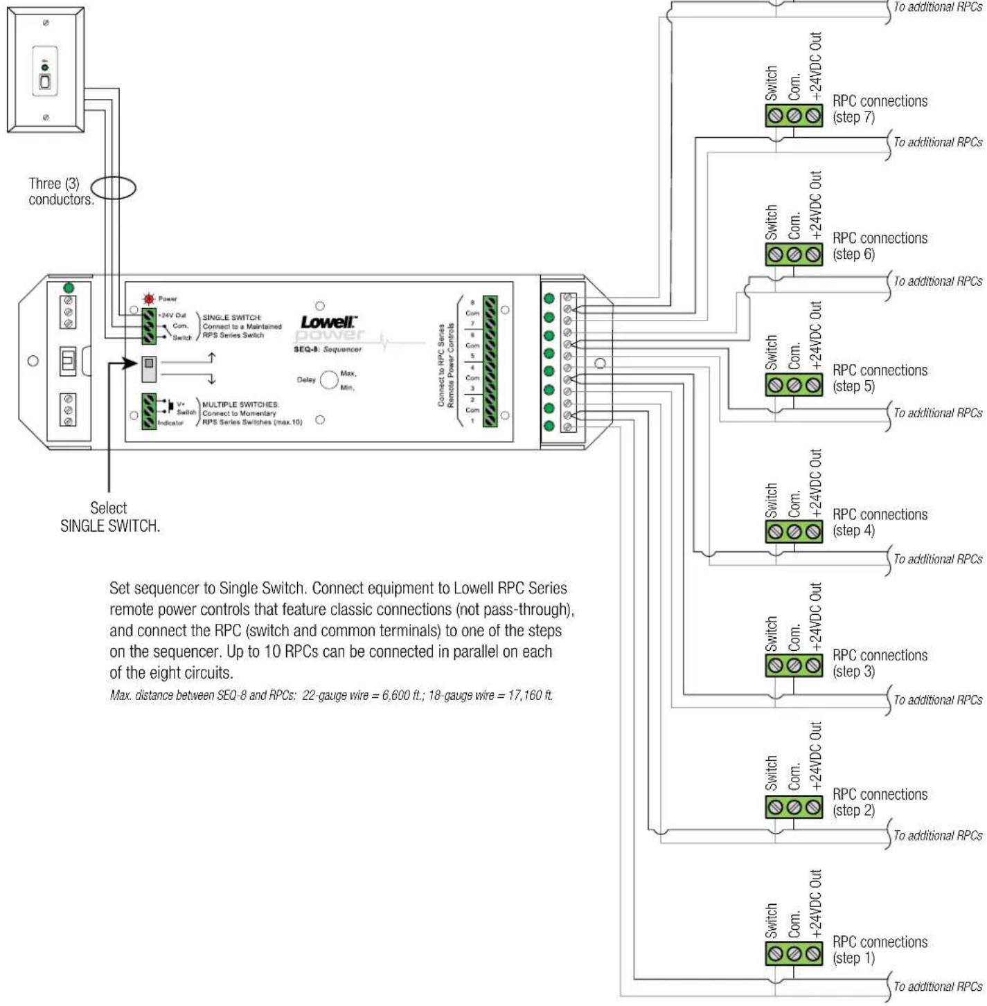
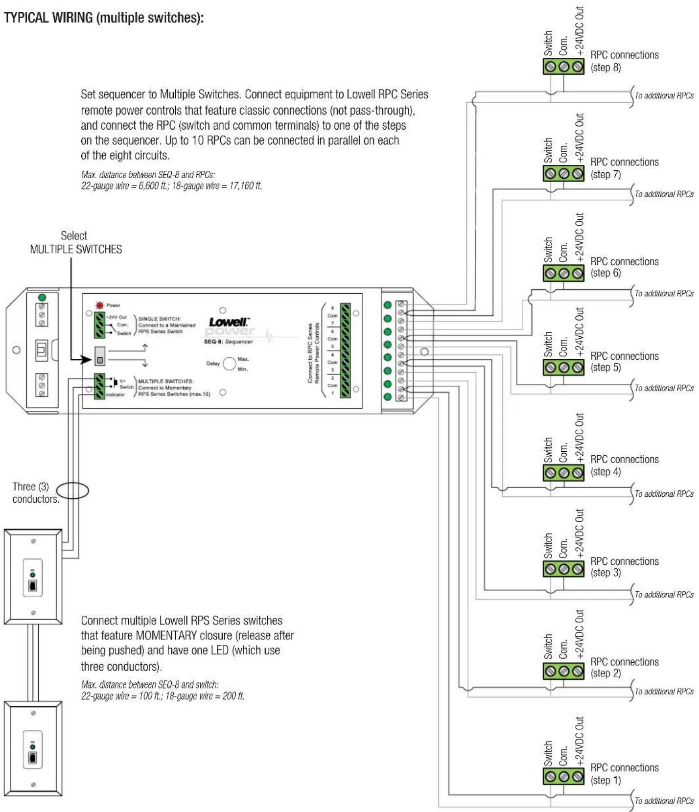
flowchart
graph TD
    A["Select MULTIPLE SWITCHES"] --> B["Three (3) conductors."]
    B --> C["Connect multiple Lowell RPS Series switches that feature MOMENTARY closure (release after being pushed) and have one LED (which use three conductors). Max. distance between SEQ-8 and switch: 22-gauge wire = 100 ft; 18-gauge wire = 200 ft."]
    C --> D["Select Multiple Switches"]
    D --> E["Select Multiple Switches to Multiple Switches. Connect equipment to Lowell RPC Series remote power controls that feature classic connections (not pass-through), and connect the RPC (switch and common terminals) to one of the steps on the sequencer. Up to 10 RPCs can be connected in parallel on each of the eight circuits. Max. distance between SEQ-8 and RPCs: 22-gauge wire = 6,600 ft; 18-gauge wire = 17,160 ft."]
    E --> F["Select Multiple Switches to Multiple Switches. Connect to Momentary RPS Series Switches (max.10)"]
    F --> G["Select Multiple Switches to Limiting to Limiting to Limiting to Limiting to Limiting to Limiting to Limiting to Limiting to Limiting to Limiting to Limiting to Limiting to Limiting to Limiting to Limiting to Limiting to Limiting to Limiting to Limiting to Limiting to Limiting to Limiting to Limiting to Limiting to Limiting to Limiting to Limiting to Limiting to Limiting to Limiting to Limiting to Limiting to Limiting to Limiting"]
    G --> H["Select Multiple Switches to Limiting to Limiting to Limiting to Limiting to Limiting to Limiting to Limiting to Limiting to Limiting to Limiting to Limiting to Limiting to Limiting to Limiting to Limiting to Limiting to Limiting to Limiting to Limiting to Limiting to Limiting to Limiting to Limiting to Limiting to Limiting to Limiting to Limiting to Limiting to Limiting to Limiting to Limiting to limit"]
    H --> I["Select Multiple Switches to Limiting to Limiting to Limiting to Limiting to Limiting to Limiting to Limiting to Limiting to Limiting to Limiting to Limiting to Limiting to Limiting to Limiting to Limiting to Limiting to Limiting to Limiting to Limiting to Limiting to Limiting to Limiting to Limiting to Limiting to Limiting to Limiting to Limiting to Limiting to Limiting to Limiting to Limiting toLimit"]
    I --> J["Select Multiple Switches to Limiting to Limiting to Limiting to Limiting to Limiting to Limiting to Limiting to Limiting to Limiting to Limiting to Limiting to Limiting to Limiting to Limiting to Limiting to Limiting to Limiting to Limiting to Limiting to Limiting to Limiting to Limiting to Limiting to Limiting to Limiting to Limiting to Limiting to Limiting to Limiting to Limiting"]
    J --> K["Select Multiple Switches to Limiting to Limiting to Limiting to Limiting to Limiting to Limiting to Limiting to Limiting to Limiting to Limiting to Limiting to Limiting to Limiting to Limiting to Limiting to Limiting to Limiting to Limiting to Limiting to Limitingto limit"]
    K --> L["Select Multiple Switches at Level 1"]
    L --> M["Select Multiple Switches at Level 2"]
    M --> N["Select Multiple Switches at Level 3"]
    N --> O["Select Multiple Switches at Level 4"]
    O --> P["Select Multiple Switches at Level 5"]
    P --> Q["Select Multiple Switches at Level 6"]
    Q --> R["Select Multiple Switches at Level 7"]
    R --> S["Select Multiple Switches at Level 8"]
    S --> T["Select Multiple Switches at Level 9"]
    T --> U["Select Multiple Switches at Level 10"]
    U --> V["Select Multiple Switches at Level 11"]
    V --> W["Select Multiple Switches at Level 12"]
    W --> X["Select Multiple Switches at Level 13"]
    X --> Y["Select Multiple Switches at Level 14"]
    Y --> Z["Select Multiple Switches at Level 15"]
    Z --> AA["Select Multiple Switches at Level 16"]
    AA --> AB["Select Multiple Switches at Level 17"]
    AB --> AC["Select Multiple Switches at Level 18"]
    AC --> AD["Select Multiple Switches at Level 19"]
    AD --> AE["Select Multiple Switches at Level 20"]
    AE --> AF["Select Multiple Switches at Level 21"]
    AF --> AG["Select Multiple Switches at Level 22"]
    AG --> AH["Select Multiple Switches at Level 23"]
    AH --> AI["Select Multiple Switches at Level 24"]
    AI --> AJ["Select Multiple Switches at Level 25"]
    AJ --> AK["Select Multiple Switches at Level 26"]
    AK --> AL["Select Multiple Switches at Level 27"]
    AL --> AM["Select Multiple Switches at Level 28"]
    AM --> AN["Select Multiple Switches at Level 29"]
    AN --> AO["Select Multiple Switches at Level 30"]
    AO --> AP["Select Multiple Switches at Level 31"]
    AP --> AQ["Select Multiple Switches at Level 32"]
    AQ --> AR["Select Multiple Switches at Level 33"]
    AR --> AS["Select Multiple Switches at Level 34"]
    AS --> AT["Select Multiple Switches at Level 35"]
    AT --> AU["Select Multiple Switches at Level 36"]
    AU --> AV["Select Multiple Switches at Level 37"]
    AV --> AW["Select Multiple Switches at Level 38"]
    AW --> AX["Select Multiple Switches at Level 39"]
    AX --> AY["Select Multiple Switches at Level 40"]
    AY --> AZ["Select Multiple Switches at Level 41"]
    AZ --> BA["Select Multiple Switches at Level 42"]
    BA --> BB["Select Multiple Switches at Level 43"]
    BB --> BC["Select Multiple Switches at Level 44"]
    BC --> BD["Select Multiple Switches at Level 45"]
    BD --> BE["Select Multiple Switches at Level 46"]
    BE --> BF["Select Multiple Switches at Level 47"]
    BF --> BG["Select Multiple Switches at Level 48"]
    BG --> BH["Select Multiple Switches at Level 49"]
    BH --> BI["Select Multiple Switches at Level 50"]
OPTIONS: (order separately)
- SWITCH for single switch applications: (RPS Series switch with maintained closure, one LED)
| Model | Description | Model | Description |
| RPSW-P | 1 LED rocker switch, white wall plate | RPSW-KP | 1 LED key switch, white wall plate |
| RPSB-P | 1 LED rocker switch, black wall plate | RPSB-R | 1 LED rocker switch, 19" panel |
| RPSB-KR | 1 LED key switch, 19" panel | RPSB-R-RJ | 1 LED rocker switch, 19" panel, RJ45 |
| RPSB-KR-RJ | 1 LED key switch, 19" panel, RJ45 | RPSW-P-RJ | 1 LED rocker switch, white wall plate, RJ45 |
| RPSW-KP-RJ | 1 LED key switch, white wall plate, RJ45 | RPSB-P-RJ | 1 LED rocker switch, black wall plate, RJ45 |
- SWITCH for multiple-switch applications: (RPS Series switch with momentary closure, one LED) ^†
| Model | Description |
| RPSW-MP | 1 LED rocker switch, white wall plate |
| RPSB-MP | 1 LED rocker switch, black wall plate |
| RPSB-MR | 1 LED rocker switch, 19" panel |
| RPSW-MKP | 1 LED key switch, white wall plate |
| RPSB-MKP | 1 LED key switch, black wall plate |
| RPSB-MKR | 1 LED key switch, 19" panel |
- REMOTE POWER CONTROL: (RPC Series with classic connections)
| Model | Description | Model | Description |
| RPC-15 | RPC with (2) 15A NEMA outlets, cord | RPC-15-S | RPC with (2) 15A NEMA outlets, surge supp, cord |
| RPC-15-SCD-RJ | RPC with (2) 15A NEMA outlets, cord, RJ45 | RPC-15-U | RPC with (2) IEC C13 oulets, cord |
| RPC-20-CD | RPC with (2) 20A NEMA outlets, cord | RPC-20-SCD | RPC with (2) 20A NEMA outlets, surge supp, cord |
| RPC-20-SCD-RJ | RPC with (2) 20A NEMA outlets, surge supp, cord, RJ45 | RPC-3N1 | RPC with (8) 15A NEMA outlets, cord |
| RPC-20-HW | RPC with (2) 20A NEMA outlets, whip | RPC-20-SHW | RPC with (2) 20A NEMA outlets, surge supp, whip |
| RPC-30-SHW | RPC with 30A Twistlock outlets, surge supp, whip |
^ Note: This sequencer is not designed for use with RPS Series switches that feature two LEDs (and require four connectors)
SEQ & SEQR Series Overview — sequencers with classic connections
| Model No. | Chassis | Steps | Alternate | REQUIRES A Remote Switch | ACCEPTS Multiple Remote Switches | ACCEPTS Input from Alarm System | Input from Lowell Switch w/RJ45 | ACCEPTS Power Input | Country of Origin | |
| Sequence Mode | Onboard Switch | |||||||||
| SEQ-4 | standalone | 4 | --- | --- | yes | through MSM2 | --- | --- | power supply | USA |
| SEQ-8 | standalone | 8 | --- | --- | yes | yes | --- | --- | power supply | USA |
| SEQR-4 | 1U panel | 4 | --- | rocker | --- | yes | yes | --- | power supply | USA |
| SEQR-4K | 1U panel | 4 | --- | key | --- | yes | yes | --- | power supply | USA |
| SEQR-8 | 1U panel | 8 | yes | rocker | --- | yes | yes | --- | power supply | USA |
| SEQR-8K | 1U panel | 8 | yes | key | --- | yes | yes | --- | power supply | USA |
| SEQR-8RJ | 1U panel | 8 | yes | rocker | --- | yes | yes | yes | power supply | USA |
Steps = Unit activates/deactivates connected remote power controls (RPCs) in four or eight steps, with a delay between each. Multiple RPCs can connect to each step. Alternate Sequence Mode = The ASM feature skips selected outputs to allow partial startup of system, useful for small events or rehearsals. It requires remote switch model RPSB-KP-ASM to enable ASM function before main switch is activated.
Onboard Switch = Sequencers without an onboard switch will require an external switch for activation.
REQUIRES A Remote Switch = Sequencer can be controlled by one external switch, usually placed in a remote location (RPS series switch with MAINTAINED closure). ACCEPTS Multiple Remote Switches = Sequencer can be controlled by one or more external switches placed in remote locations (RPS Series switches with MOMENTARY closure). Some models require the MSM2 module in order to accept multiple switches.
ACCEPTS Input from Alarm System = Sequencer can accept control override from an alarm system (alarm by others, not included).
ACCEPTS Input from Lowell Switch w/RJ45 = Sequencer is designed for use with a Lowell MOMENTARY switch that has a model number with "-RJ" as a suffix (see options above). Note that these switches include a single RJ45 connector and are not part of Lowell's "pass-through" series.
NOTE: For rackmount sequencers that include AC power outlets, see Lowell ACR Series or ACSPR Series.
Brand : Lowell
Model : SEQ-8
Category : Séquenceur basse tension