
VLHDMIMAT4X2RS - Switch Vivolink - Free user manual and instructions
Find the device manual for free VLHDMIMAT4X2RS Vivolink in PDF.


| Product Type | HDMI Matrix Switch |
| Brand | Vivolink |
| Model | VLHDMIMAT4X2RS |
| Number of Inputs | 4 |
| Number of Outputs | 2 |
| Video Resolution | Up to 4K@60Hz |
| HDMI Version | HDMI 2.0 |
| HDCP Support | HDCP 2.2 |
| Audio Support | PCM, Dolby Digital, DTS |
| Control Method | IR Remote, RS-232, LAN |
| Power Supply | DC 12V / 1A |
| Power Consumption | < 10W |
| Dimensions (W x D x H) | 200 x 100 x 25 mm |
| Weight | 0.5 kg |
| Operating Temperature | 0°C to 40°C |
| Storage Temperature | -20°C to 60°C |
| Housing Material | Metal |
| Mounting | Rack or desk |
| Main Features | Matrix switching, EDID management, independent output switching |
| Maintenance | Clean with dry cloth, avoid liquids |
| Safety | Keep away from moisture, do not disassemble |
| Spare Parts | Contact Vivolink support |
| Repairability | Not user-serviceable, professional repair required |
| Certifications | CE, FCC, RoHS |
Frequently Asked Questions - VLHDMIMAT4X2RS Vivolink
User questions about VLHDMIMAT4X2RS Vivolink
0 question about this device. Answer the ones you know or ask your own.
Ask a new question about this device
Download the instructions for your Switch in PDF format for free! Find your manual VLHDMIMAT4X2RS - Vivolink and take your electronic device back in hand. On this page are published all the documents necessary for the use of your device. VLHDMIMAT4X2RS by Vivolink.
USER MANUAL VLHDMIMAT4X2RS Vivolink
4x2 HDMI 2.0 Presentation Switcher with Matrix Outputs

Preface
Read this user manual carefully before using the product. Pictures are shown in this manual for reference only. Different models and specifications are subject to real product.
This manual is only for operation instruction, please contact the local distributor for maintenance assistance. The functions described in this version were updated till October, 2019. In the constant effort to improve the product, we reserve the right to make functions or parameters changes without notice or obligation. Please refer to the dealers for the latest details.
Trademarks
Product model, Vivolink and its logo are trademarks of Vivolink. Any other trademarks mentioned in this manual are acknowledged as the properties of the trademark owner. No part of this publication may be copied or reproduced without the prior written consent of Vivolink.
FCC Statement
This equipment generates, uses and can radiate radio frequency energy and, if not installed and used in accordance with the instructions, may cause harmful interference to radio communications. It has been tested and found to comply with the limits for a Class B digital device, pursuant to part 15 of the FCC Rules. These limits are designed to provide reasonable protection against harmful interference in a commercial installation.
Operation of this equipment in a residential area is likely to cause interference, in which case the user at their own expense will be required to take whatever measures may be necessary to correct the interference.
Any changes or modifications not expressly approved by the manufacture would void the user's authority to operate the equipment.

SAFETY PRECAUTIONS
To ensure the best performance from the product, please read all instructions carefully before using the device. Save this manual for further reference.
- Unpack the equipment carefully and save the original box and packing material for possible future shipment.
- Follow basic safety precautions to reduce the risk of fire, electrical shock and injury to persons.
- Do not dismantle the housing or modify the module. It may result in electrical shock or burn.
- Using supplies or parts not meeting the products' specifications may cause damage, deterioration or malfunction.
• Refer all servicing to qualified service personnel.
- To prevent fire or shock hazard, do not expose the unit to rain, moisture or install this product near water.
- Do not put any heavy items on the extension cable in case of extrusion.
- Do not remove the housing of the device as opening or removing housing may expose you to dangerous voltage or other hazards.
- Install the device in a place with fine ventilation to avoid damage caused by overheat.
- Keep the module away from liquids.
- Spillage into the housing may result in fire, electrical shock, or equipment damage. If an object or liquid falls or spills on to the housing, unplug the module immediately.
- Do not twist or pull by force ends of the optical cable. It can cause malfunction.
- Do not use liquid or aerosol cleaners to clean this unit. Always unplug the power to the device before cleaning.
- Unplug the power cord when left unused for a long period of time.
- Information on disposal for scrapped devices: do not burn or mix with general household waste, please treat them as normal electrical wastes.
- Product Introduction......1
1.1 Features .... 1
1.2 Package List....1
-
Specification 2
-
Panel Description....4
3.1 Front Panel 4
3.2 Rear Panel....5
-
System Connection....6
-
Button Control....7
5.1 Manual Switching ....7
5.2 Auto Switching....7
5.3 EDID Setting....8
- IR Remote Control....9
- Web Control....10
- RS232 Control 12
8.1 System Control Commands....12
8.2 Signal Switching Commands....14
8.3 EDID Setting Commands....15
8.4 Audio Setting Commands 15
- Firmware Upgrade....16
1. Product Introduction
Thank you for choosing the VLHDMIMAT4X2RS 4x2 HDMI 2.0 presentation switcher with matrix outputs. The switcher consists of four HDMI inputs, two HDMI matrix outputs and full HDMI 2.0 support. The product offers SPDIF and 3.5mm output for dual HDMI OUT audio extraction and dual HDMI OUT ARC along with 4K to 1080p down-scaling functionality. The VLHDMIMAT4X2RS features a wide range of control flexibility via Web, RS232, IR and smart EDID management.
1.1 Features
- 4x2 HDMI presentation switcher with matrix outputs.
• HDMI 2.0b, 4K@60Hz 4:4:4 8bit, HDR 10, HDCP 2.2.
• 4K to 1080p down-scaling.
- SPDIF and 3.5mm output for dual HDMI OUT audio extraction and dual HDMI OUT ARC.
• RS232, IR and TCP/IP control.
• Smart EDID management.
1.2 Package List
• 1x VLHDMIMAT4X2RS 4x2 HDMI 2.0 presentation switcher
• 2x Mounting Ears with 4 Screws
- 4x Plastic Cushions
- 1x IR Remote
• 1x IR Receiver
• 1x 3-pin Terminal Block
• 1 x Power Adapter (12V DC,1A)
- 1x User Manual
Note: Please contact your distributor immediately if any damage or defect in the components is found.
- Specification
| Video Input | |
| Video Input | (4) HDMI |
| Video Input Connector | (4) Type-A female HDMI |
| Video Input Video Resolution | Up to 4K@60Hz 4:4:4 8bit |
| HDMI Audio Format | Supports Dolby Atmos, Dolby TrueHD, Dolby Digital Plus, Dolby Digital, DTS-X, DTS-HD Master Audio, DTS 5.1, 2 - 8Ch PCM 32-192KHz 16-24 bits; 2 - 8Ch PCM 32-192kHz 16-24 bits. |
| HDMI Input Cable | 4K@60Hz 4:4:4 ≤ 3 meters, other ≤ 5 meters |
| Video Output | |
| Video Output | (2) HDMI |
| Video Output Connector | (2) Type-A Female HDMI |
| Video output Video Resolution | OUT A: Up to 4K@60Hz 4:4:4 8bit, HDR10, Dolby Vision, supports color space 4:2:2/4:2:0 to 4:4:4, 4K to 1080p down-scaling. |
| OUT B: Up to 4K@60Hz 4:4:4 8bit, HDR, Dolby Vision | |
| HDMI Output Cable | ≤ 5 meters |
| HDMI Version | Up to 2.0 |
| HDCP Version | Up to 2.2 |
| Digital SPDIF Audio Output | |
| Audio Output | (1) Digital SPDIF audio |
| Audio Output Connector | (1) Toslink connector |
| Output level | ±0.05dBFS |
| Frequency Response | 20Hz~20KHz, ±1dB |
| THD+N | < 0.05%, 20Hz~20KHz bandwidth, 1KHz sine at 0dBFS level (or max level) |
| SNR | >90dB, 20Hz~20KHz bandwidth |
| Crosstalk isolation | <-70dB, 10KHz sine at 0dBFS level (or max level before clipping) |
| Noise Level | -90dB |
| Unbalanced analog Audio Output | |
| Audio Output | (1) Unbalanced analog audio |
| Audio Output Connector | (1) 3.5mm jack |
| Frequency Response | 20Hz~20KHz, ±1dB |
| Max output level | 2.0Vrms ± 0.5dB. 2V=16dB headroom above-10dBV (316 mV) nominal consumer line level signal |
| THD+N | < 0.05%, 20Hz~20KHz bandwidth, 1KHz sine at 0dBFS level (or max level) |
| SNR | >80dB, 20Hz~20KHz bandwidth |
| Crosstalk isolation | <-80dB, 10KHz sine at 0dBFS level (or max level before clipping) |
| L-R level deviation | < 0.05dB, 1KHz sine at 0dBFS level (or max level before clipping) |
| Output load capability | 1Kohm and higher (supports 10x paralleled 10Kohm loads) |
| Noise Level | -80dB |
| Control Part | |
| Control Port | (1) EDID Switch, (1) FW, (1) RS232, (1) IR IN, (1) TCP/IP |
| Control Connector | (1) 4-pin DIP Switch, (1) Micro-USB, (1) 3-pin terminal block, (1) 3.5mm jack, (1) RJ45 |
| General | |
| Bandwidth | 18Gbps |
| Operation Temperature | -5°C ~ +55°C |
| Storage Temperature | -25°C ~ +70°C |
| Relative Humidity | 10%-90% |
| External Power Supply | Input: AC 100~240V, 50/60Hz; Output: 12V DC 1A |
| Power Consumption | 7.5W (Max) |
| Dimension (W*H*D) | 200mm x 28.5mm x 100mm |
| Net Weight | 605g |
3. Panel Description
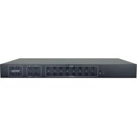
3.1 Front Panel
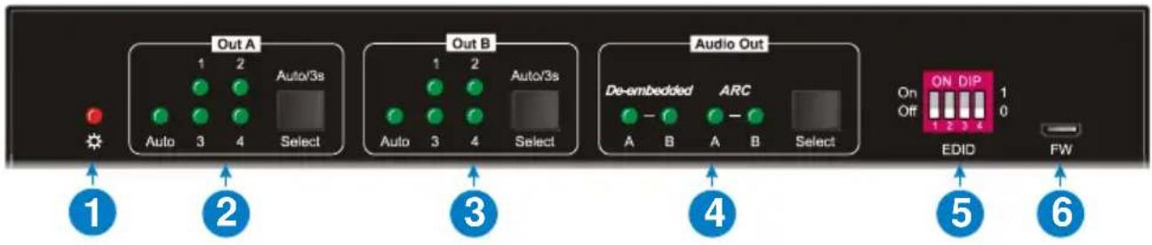
① Power LED: Illuminates solid red when the device is powered on.
② Out A:
- 1-4: Four HDMI input LEDs, one of which illuminates green to indicate which source is selected.
• Auto LED: Illuminates green in auto switching mode. - Select/Auto/3s: Press the button repeatedly to cycle through the four video inputs. Press and hold the button for 3 seconds to enter or exit auto switching mode.
③ Out B:
- 1-4: Four HDMI input LEDs, one of which illuminates green to indicate which source is selected.
• Auto LED: Illuminates green in auto switching mode. - Select/Auto/3s: Press the button repeatedly to cycle through the four video inputs. Press and hold the button for 3 seconds to enter or exit auto switching mode.
④ Audio Out:
- De-embedded: Two HDMI de-embedded audio source LEDs, one of which illuminates green to indicate output A or output B de-embedded audio source is selected for audio output.
- ARC: Two ARC audio source LEDs, one of which illuminates green to indicate output A or output B ARC audio source is selected for audio output.
- Select: Press the button to select audio source.
⑤ EDID: 4-pin DIP switch for EDID setting.
⑥ FW: Micro-USB port for firmware upgrade.
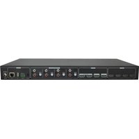
3.2 Rear Panel

① Inputs 1\~4: Connects to HDMI sources.
② Outputs (ARC) A\~B: Connects to display devices. They supports ARC, and only the output A port supports color space 4:2:2/4:2:0 to 4:4:4 and 4K to 1080p down-scaling function for compatibility with more display devices.
③ Audio Out: Toslink connector and 3.5mm jack for audio output. There are four audio can be selected: output A de-embedded audio, output B de-embedded audio, output A ARC audio or output B ARC audio.
④ RS232: Connects to control device (e.g. PC) to control the switcher by sending RS232 commands.
⑤ IR EYE: Connects to IR receiver to control the switcher by the IR remote.
⑥ TCP/IP: Connects to the control device (e.g. PC) to control the switcher by Web.
⑦ DC 12V: DC connector for the power adapter connection.
4. System Connection
The following diagram illustrates the typical input and output connection of the switcher:
![graph TD A["Game Console"] --> B["4K TV 4K TV"] C["Game Console"] --> D["4K TV 4K TV"] E["Blu-ray"] --> F["4K TV 4K TV"] G["Laptop"] --> H["1080p TV"] I["4K TV 4K TV"] --> J["Down-scale"] K["1x Ib"] --> L["Audio Out"] M["RS232"] --> N["1x Ib"] O["IR EYE"] --> P["TCP/IP"] Q["IR Receiver"] --> R["Lapt…](/content/2026/05/1013367/images/0778f87b2ecd42fc451e2df195bb6c9075d13651b67f219e11e007852d382878.jpg)
ARC Connection:
![graph TD A["Blu-ray"] -->|HDMI:| B["4K TV 4K TV"] A -->|ARC Audio:| C["Soundbar"] A -->|Down-Scaler| D["Audio Out"] D --> E["RS232"] D --> F["IR EYE"] D --> G["DC 12V"] B --> H["4K TV 4K TV"] C --> I["Soundbar"] C --> J["Amplifier"]](/content/2026/05/1013367/images/e78f793b392c5c4e4bd5566dde6e30039978bb3ba8d8fedd32ca07abf42934f2.jpg)
5. Button Control
5.1 Manual Switching
When the switcher is in manual switching mode, the AUTO button LED goes out. Please follow the below steps to switch input source to output channel.
1) Press Select button at Out A block to select input source for output A, and the corresponding source LED turns green.
2) Press Select button at Out B block to select input source for output B, and the corresponding source LED turns green.
5.2 Auto Switching
Press and hold Select button at least 3 seconds at Out A block to enable auto switching mode for output A, and then the Auto LED will turns green.
Press and hold Select button at least 3 seconds at Out B block to enable auto switching mode for output B, and then the Auto LED will turns green.
When in auto switching mode, the switcher will switch according to the following rules:
- The switcher will switch to the first available active input starting at input 1 to 4.
- New input: The switcher will automatically select the new input once detecting a new input.
- Reboot: If power is restored to the switcher, it will automatically reconnect the input before powered off.
- Source removed: When an active source is removed, the switcher will switch to the first available active input starting at HDMI input 1.
- Detection method: TMDS or 5V (The default is 5V and it can be selected by RS232 commands).
- Press the Select button can switch to next input source, and the switcher doesn't exit the auto switching mode.
Note: In auto switching mode, press and hold the Select button at least 3 seconds to enable manual switching mode, but the input source will not be switched.
5.3 EDID Setting
The Extended Display Identification Data (EDID) is used by the source device to match its video resolution with the connected display. The 4-pin DIP switch on the front panel can be used to set the EDID to a fixed value to ensure the compatibility in the video resolution.
The switch represents "0" when in the lower (OFF) position, and it represents "1" while putting the switch in the upper (ON) position.

Switch 1\~3 are used for built-in EDID setting, and switch 4 is used for mode setting.
The DIP switch status and its corresponding setting are shown as below chart.
| Switch 1~3 Status | Video Resolution | Audio Format |
| 000 | Pass-through | Pass-through |
| 001 | 1920x1080@60Hz 8bit | Stereo |
| 010 | 3840x2160@30Hz 8bit | Stereo |
| 011 | 3840x2160@30Hz 8bit HDR | Stereo |
| 100 | 3840x2160@30Hz Deep Color HDR | PCM 5.1 |
| 101 | 3840x2160@60Hz 8bit | Stereo |
| 110 | 3840x2160@60Hz Deep Color HDR | PCM 5.1 |
| 111 | User-defined EDID | |
| Switch 4 Status | Mode | |
| 0 | Global Mode. | |
| 1 | Out B Private Mode. | |
EDID setting rules:
When switching one input to output A and output B, the switcher is used as a 1x2 splitter, the input source device obtains its EDID from the output display with priority output B>output A. If video switching fails in EDID pass-through mode, set the built-in EDID to 1080p.
1) When the specifications of output A and output B display devices are same, set the EDID to Global Mode. When switch same input to output A and output B, because the supported resolution (4K@60Hz 4:4:4) of two outputs are same, the input source device will not reread the EDID of display device to ensure non-flash screen.
2) When the specifications of output A and output B display devices are different, set the EDID to Out B Private Mode, and the Out A is in Pass-through mode.
√ When switching the input source of output A to output B, because the input source device will first learn the EDID from output B, so the two output displays will flash before the image appears.
√ When switching the input source of output B to the output A, because the input source device will first learn the EDID from output B, so the display device of output B doesn't flash, but the display device of output A will flash before the image appears.
6. IR Remote Control
Connect IR receiver to the IR EYE port, the switcher can be controlled by the following IR remote.

① 1-4: Press 1-4 button to select corresponding input source for OUT A.
AUTO: Press the button to enable auto switching mode for OUT A.
② 1-4: Press 1-4 button to select corresponding input source for OUT B.
AUTO: Press the button to enable auto switching mode for OUT B.
③ De-embedded: Press A or B button to select output A or output B de-embedded audio for audio output.
ARC: Press A or B button to select output A or output B ARC audio for audio output.
7. Web Control
The switcher can be controlled via WEB GUI (not telnet).
The default IP settings are:
IP Address: 192.168.0.178
Subnet Mask: 255.255.255.0
Type 192.168.0.178 in the internet browser, it will enter the below log-in webpage:
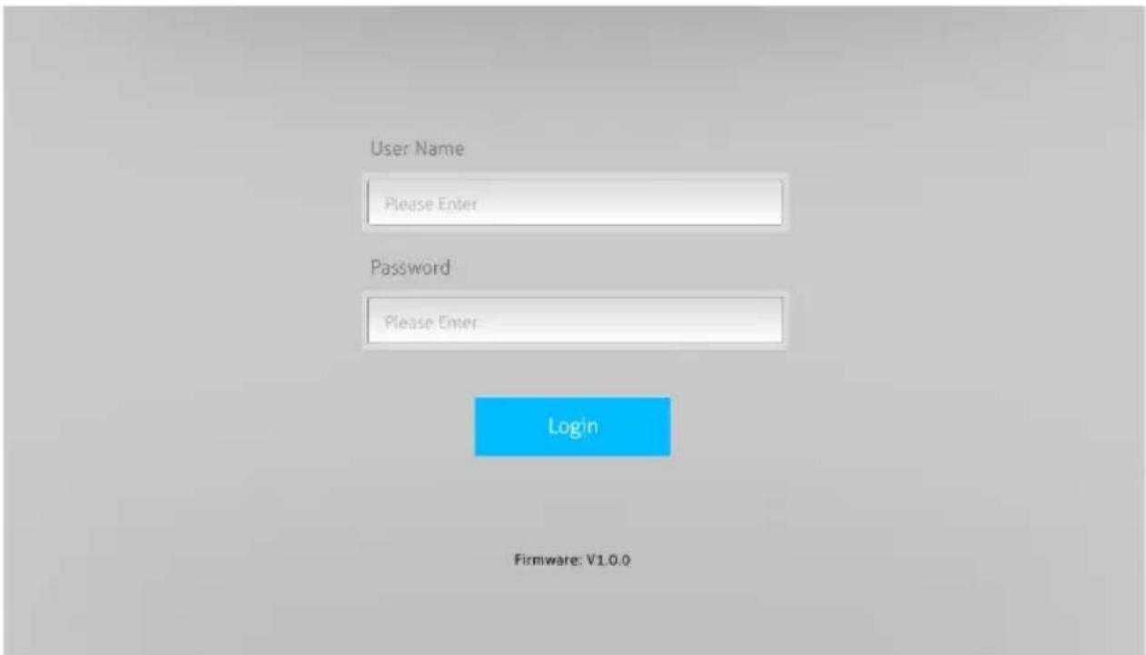
Username: admin
Password: admin
Type the user name and password, and then click Login to enter the below control tab.
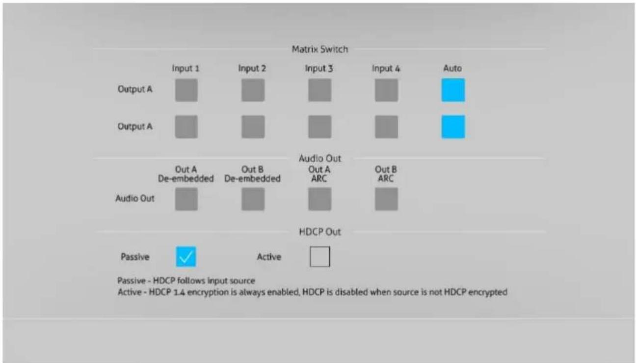
- Matrix Switch: Select Input 1\~4 for output A or output B to build matrix switching. Select AUTO to enable auto switching mode for output A or output B.
- Audio Out: Select output A de-embedded audio, output B de-embedded audio, output A ARC audio or output B ARC audio for Toslink and 3.5mm jack audio outputs.
• HDCP Out: Select Passive or Active mode.
8. RS232 Control
Connect the RS232 port to control device (e.g. PC) with RS232 cable. The switcher can be controlled by sending RS232 commands.
RS232 Commands:
The command lists are used to control the switcher. The RS232 control software (e.g. docklight) needs to be installed on the control PC to send RS232 commands.
Communication protocol: RS232 Communication Protocol
Baud rate: 9600
Data bit: 8
Stop bit: 1
Parity bit: none
Note:
- All commands needs to be ended with "
" - In the commands, “[”and “]” are symbols for easy reading and do not need to be typed in actual operation.
• Type the command carefully, it is case-sensitive.
8.1 System Control Commands
| Command | Description | Command Example and Feedback | |
| >SetPowerOn Dis | System standby. | ||
| >SetPowerOn En | System on. | ||
| >GetPowerOn | Get the system power status. | ||
| >GetFirmwareVersion | Get firmware version. | ||
| >SetFactoryReset | Reset to factory default. | ||
| >SetReboot | System reboot. | ||
| >GetStatus | Get device status. | ||
| >SetIpAddr XXX.XXX.XXX.XXX | Set static IP address to XXX.XXX.XXX.XXX | ||
| >GetIpAddr | Get IP address. | ||
| >SetRS232Baudrate [PARAM] | Set the baud rate of switcher to [PARAM]. [PARAM]=1~7. | >SetRS232Baudrate 5 | |
| [PARAM] | Baud Rate | ||
| 1 | 115200 | ||
| 2 | 57600 | <RS232Baudrate 9600 | |
| 3 | 38400 | ||
| 4 | 19200 | ||
| 5 | 9600 | ||
| 6 | 4800 | ||
| 6 | 2400 | ||
| >GetRS233Baudrate | Get the baud rate of switcher. | ||
| >SetKeyboardLock [PARAM] | Unlock/lock front panel buttons and IR remote buttons.[PARAM]=Dis, EnDis: Unlock; En: Lock | >SetKeyboardLock Dis | |
| >GetKeyboardLock | Get the buttons locking status. | ||
| >SetDhcp [PARAM] | Enable or disable DHCP.[PARAM]=En, DisEn: Enable DHCP, the switcher automatically get IP.Dis: Disable DHCP, Manually set the IP of switcher.After reset the switcher, the DHCP is enabled, and the switcher will automatically get IP again. | >SetDhcp En | |
| >GetDhcp | Get DHCP status. | ||
| >SetSubnetMask XXX.XXX.XXX.XXX | Set subnet mask to XXX.XXX.XXX.XXX. | ||
| >GetSubnetMask | Get subnet mask. | ||
| >SetGateWay XXX.XXX.XXX.XXX | Set gateway to XXX.XXX.XXX.XXX. | ||
| >GetGateWay | Get gateway. | ||
| >SetMacAddrXX:XX:XX:XX:XX:XX | Set the MAC address to XX:XX:XX:XX:XX:XX. | ||
| >GetMacAddr | Get the MAC address. | ||
8.2 Signal Switching Commands
| Command | Description | Command Example and Feedback |
| >SetAV [PARAM1] [PARAM2] | Switch HDMI input [PARAM2] to output [PARAM1].[PARAM1]=A, B[PARAM2] = H1, H2, H3, H4 | >SetAV B H1 |
| >GetAV | Get the input channel on output channel one by one. | |
| >SetAutoSwitch [PARAM1] [PARAM2] | Enable/disable the auto switching mode for the output A or output B.[PARAM1] = A,B[PARAM2]= En, DisEn: Enable auto switching mode.Dis: Disable auto switching mode. | >SetAutoSwitch B En |
| >GetAutoSwitch | Get the auto switching mode of output A and output B. | |
| >SetSignalDet [PARAM] | Set the signal auto detection method to [PARAM]. [PARAM]= 5V, TMDS.The default detection method is 5V. | >SetSignalDet 5V |
| >GetSignalDet | Get the signal auto detection method. | |
| >UpDownScaler [PARAM] | Enable/disable down-scaling function of output A.[PARAM]=En, DisEn: Enable down-scaling function.Dis: Disable down-scaling function. | >UpDownScaler En |
| >GetDownScaler | Get the down-scaling function of output A. | |
| >SetHdcpOutput | Set HDCP output mode. | >SetHdcpOutput Passive |
| [PARAM] | [PARAM]= Passive, ActivePassive: The HDCP version of output follows the HDCP of input source.Active: The HDCP version of output is up to 1.4 | |
| >GetHdcpOutput | Get HDCP output mode. |
8.3 EDID Setting Commands
| Command | Description | Command Example and Feedback |
| >SetUpdateEdid | Upload user-defined EDID. The EDID DIP switch should be set as “1111”. |
8.4 Audio Setting Commands
| Command | Description | Command Example and Feedback |
| >SetAudioSrc [PARAM] | Set the audio source of analog audio and SPDIF audio.[PARAM]= 1, 2, 3, 41: OUTA de-embedded2: OUTB de-embedded3: OUTA ARC4: OUTB ARC | >SetAudioSrc 1 |
| >SetSpdif [PARAM] | Mute/unmute the SPDIF audio output.[PARAM]=Mute, UnMute. | >SetSpdif Mute |
| >Setlis [PARAM] | Mute/unmute the analog audio output (3.5mm jack). [PARAM]=Mute, UnMute. | >Setlis UnMute |
| >GetAudioSta | Get audio status. |
9. Firmware Upgrade
Please follow the steps below to upgrade the firmware by the FW port on the front panel:
1) Prepare the latest upgrade file (.bin) and rename it as "FW_MERG.bin".
2) Connect the switcher to the PC with USB to Micro USB cable, and then power on the switcher. The PC will automatically detect a U-disk named of "BOOTDISK".
3) Double-click the U-disk, a file named of "READY.TXT" would be showed.
4) Directly copy the latest upgrade file (.bin) to the "BOOTDISK" U-disk.
5) Reopen the U-disk to check the filename "READY.TXT" whether automatically becomes "SUCCESS.TXT", if yes, the firmware was updated successfully, otherwise, the firmware updating is fail, the name of upgrade file (.bin) should be confirm again, and then follow the above steps to update again.
6) Remove the USB to Micro USB cable after firmware upgrade, and reboot the switcher.
- 4X2 HDMI 2.0 PRESENTATION SWITCHER WITH MATRIX OUTPUTS
- PREFACE
- TRADEMARKS
- FCC STATEMENT
- SAFETY PRECAUTIONS
- PRODUCT INTRODUCTION
- 1.1 FEATURES
- 1.2 PACKAGE LIST
- PANEL DESCRIPTION
- 3.1 FRONT PANEL
- 3.2 REAR PANEL
- SYSTEM CONNECTION
- BUTTON CONTROL
- 5.1 MANUAL SWITCHING
- 5.2 AUTO SWITCHING
- 5.3 EDID SETTING
- EDID SETTING RULES
- IR REMOTE CONTROL
- WEB CONTROL
- RS232 CONTROL
- RS232 COMMANDS
- NOTE
- 8.3 EDID SETTING COMMANDS
- 8.4 AUDIO SETTING COMMANDS
- FIRMWARE UPGRADE
Brand : Vivolink
Model : VLHDMIMAT4X2RS
Category : Switch