MODEL 296t - Keyboard Tiptop Audio - Free user manual and instructions
Find the device manual for free MODEL 296t Tiptop Audio in PDF.


| Product Type | Programmable Spectral Processor (Eurorack Module) |
| Model | MODEL 296t |
| Brand | Tiptop Audio |
| Size | 52 HP, Depth: 52 mm |
| Power Consumption | +12V 360 mA, -12V 350 mA |
| Number of Frequency Bands | 16 |
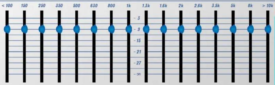
| Frequency Ranges | < 100 Hz, 150 Hz, 250 Hz, 350 Hz, 500 Hz, 630 Hz, 800 Hz, 1 kHz, 1.3 kHz, 1.6 kHz, 2 kHz, 2.6 kHz, 3.5 kHz, 5 kHz, 8 kHz, > 10 kHz |
| Signal Inputs | All, Even, Odd (each with 0 dB nominal level) |
| Attenuated Outputs | All, Even, Odd (affected by slider positions) |
| Individual Band Outputs | 16 individual 0 dB outputs (unaffected by sliders) |
| Comb Filter Outputs | Even and Odd (0 dB, unaffected by sliders) |
| Envelope Follower Outputs | 16 CV outputs (0-10V) tracking band amplitude |
| Programmed Outputs | All, Even, Odd (controlled by Program Control and Local CV) |
| Controls | 16 slider attenuators, Frequency knob (with CV and attenuverter), Width knob (with CV and attenuator), Envelope Decay switch (Long/Combo/Short), Programmed Spectrum Transfer switches (Even→Odd, Odd→Even), Pre-Emphasis knobs (Even, Odd) |
| CV Inputs | Frequency (with attenuverter), Width (with attenuator), 16 Local Program CV inputs |
| LED Indicators | 16 LEDs driven by envelope followers (indicate 10Vpp signal level) |
| Filter Band Cards | 8 vertically mounted, flexible, securely connected |
| Compatibility | Buchla 200 series / Eurorack |
| Power Supply Note | Requires regulated supply (e.g., Mantis); ensure total module consumption does not exceed case capacity |
| Cleaning | Wipe with a dry, lint-free cloth. Do not use liquids or solvents. |
| Safety | Do not expose to moisture or extreme temperatures. Disconnect power before installation or removal. |
| Repairability | Filter band cards are replaceable by qualified technician; consult factory for service. |
Frequently Asked Questions - MODEL 296t Tiptop Audio
User questions about MODEL 296t Tiptop Audio
0 question about this device. Answer the ones you know or ask your own.
Ask a new question about this device
Download the instructions for your Keyboard in PDF format for free! Find your manual MODEL 296t - Tiptop Audio and take your electronic device back in hand. On this page are published all the documents necessary for the use of your device. MODEL 296t by Tiptop Audio.
USER MANUAL MODEL 296t Tiptop Audio
PROGRAMMABLE SPECTRAL PROCESSOR - MODEL 296t
Envelope Follower Outputs
tracks the amplitude of each bandpass filter and converts it into CV to be sent to modulate any other parameter in the system.
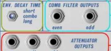
Env. Decay Time
adjusts the decay shape of the Envelope Follower's CV.
Comb Filter Outputs
are unattenuated audio outs of Even and Odd collection of bandpass filters.
Individual Audio Outputs
for each bandpass filter to be sent for further processing and/or to be used as a modulation source (i.e. FM).
Attenuated Outputs
these are affected by the individual bandpass slider positions and are mixed at the All output or split into Even and Odd outputs. Great for stereo effect.
PROGRAMMABLE SPECTRAL PROCESSOR MODEL 296t

bar
| Category | Value | |---|---| | < 100 | -9 | | 150 | -9 | | 250 | -9 | | 350 | -9 | | 500 | -9 | | 630 | -9 | | 800 | -9 | | 1k | -9 | | 1.3k | -9 | | 1.6k | -9 | | 2k | -9 | | 2.6k | -9 | | 3.5k | -9 | | 5k | -9 | | 8k | -9 | | > 10k | -9 |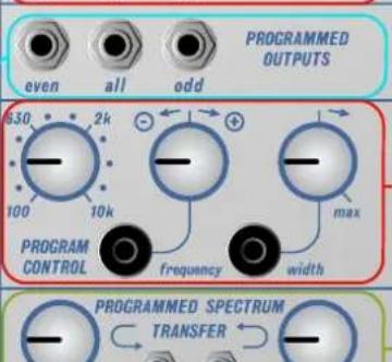

Programmed Outputs
are not affected by the slider positions, rather they are affected by the Program Control, Programmed Spectrum Transfer and Local Program CV Inputs.
Just like the Attenuated Outputs its audio outputs are Even, Odd and Mixed.
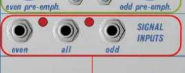
Signal Inputs use both even and odd inputs especially in tandem with the Programmed Spectrum Transfer section for vocoding effects.
Program Control
the left potentiometer manually sweeps through the frequency bands or can respond to CV via its frequency jack and attenuverter potentiometer. The width has a CV jack with an attenuator potentiometer. With the pot fully counter-clockwise the width responses as a VCA. Offsetting this pot determines the width of the bandpass filters engaged.
Programmed Spectrum Transfer
section applies the spectrum from the even bandpass filters to the odd filters (left switch) or odd to even (right switch).
Pre-Emphasis pots add gain to even or odd highs respectively.
Specifications:
Size: 52 HP - Depth: 52 mm
Power: +12V 360mA / -12V 350mA
Buchla TIPTOPaudio
Eurorack 200 series
PROGRAMMABLE SPECTRAL PROCESSOR - MODEL 296t
Please note:
On the back of your 296t are eight vertically mounted filter band cards. The cards are flexible and can move few millimeters left and right, this is normal and no need to be alarmed, the cards are firmly secured to the connector and require strong force to be pulled out.
The 296t consumes 360mA from the +12V rail and 350mA from the -12V rail. It is important to have a strong regulated power supply like Mantis to power it. Make sure to calculate the power consumption of all the other modules in your case to make sure all the modules combined do not overload your power rails and the maximum current the external power adapter that your case can supply.
User Instructions:
Transcribed from Buchla Synthesizer User Guide November 16, 1982 written by Daniel J. Schedit and modified for the 296t.
The PROGRAMMABLE SPECTRAL PROCESSOR is an elaborate set of filters with a number of different outputs and special functions. Perhaps its most obvious function is that of a sixteen band "graphic equalizer". The sixteen bands are labeled in hex numerals (0 through F) at the top and bottom of the module and the centre frequency of each band is indicated above each slider attenuator.
ATTENUATOR OUTPUTS
The signal input jacks, in the bottom right, offer the choice of putting a signal into the eight even numbered bands, all sixteen bands, or the eight odd bands. Note that these are just the even or odd numbered bands on the equalizer and have no correspondence to even or odd harmonics.) The ATTENUATOR OUTPUTS on the right of the module also offer "even", "odd", or "all" signal outputs. With a signal patched into the "ALL" signal input and taken out through the "ALL" attenuator output the module functions just as a sixteen band graphic equalizer. Note on the scale for the attenuators that -3dB is the top range of the sliders and that a slider at the very top is actually giving -3dB to frequencies in that band. An attenuator at the very bottom will completely cut off any signal in that frequency band.
The signal output jacks directly above each attenuator offer the signal present within that frequency band at 0dB. These outputs are not affected by the attenuator's positions. The COMB FILTER, outputs offer the signals from either all the "even" or all the "odd" bands and are also unaffected by the attenuators and are set at 0dB.
CONTROL VOLTAGE OUTPUTS
The control voltage outputs labeled ENVELOPE OUTPUTS are envelope follower outputs for each frequency band. In other words, the voltage from these outputs represents the amplitude of the signal present within each band. The switch in the upper right selects "long" "combo" or "short" envelope decay times. These outputs are not affected by the positions of the attenuators.
PROGRAMMED OUTPUTS
The SPECTRAL PROCESSOR can be voltage controlled in a variety of ways. The results of any control voltage manipulation are presented to the PROGRAMMED outputs. It is possible to "sweep" through the various frequency bands (much like a bandpass filter can "sweep" the frequency spectrum) using the left knob on the PROGRAM CONTROL section. This knob can be voltage controlled through the control voltage input labeled FREQUENCY. The knob beside the input is an inverting attenuator the same as others on the synthesizer. On the right is a WIDTH control knob which determines the widths of the sixteen frequency bands. The labeling above each attenuator indicates the approximate center frequency of each band. Notice that as the bandwidth gets very narrow "gaps" appear between each band and then the bands disappear completely and no signal is passed. At the MAX setting each band is so wide as to encompass the entire frequency spectrum and the FREQ control will have no effect. This knob can be voltage controlled but it has no attenuator on the control voltage. The LOCAL PROGRAM INPUTS allow individual voltage control of the signal level in each frequency band. With no control voltage the signal for that band is cut off. As a control voltage increases the signal is gradually unattenuated.
PROGRAMMABLE SPECTRAL PROCESSOR - MODEL 296t
SPECTRAL BIAS
The pair of knobs and switches labeled PROGRAMMED SPECTRUM TRANSFER have a function often associated with a "vocoder" circuit. The left switch, when up, patches each "even" envelope follower output into its neighboring "odd" control voltage input. In effect this causes the SPECTRAL PROCESSOR to analyze the signal present at the "even" input and to duplicate its frequency spectrum in the "odd" bands. If the signal presented to the "odd" input has a broad enough frequency spectrum itself the "odd" PROGRAMMED OUTPUTS will match timbres with the "even" signal. The right switch performs the same function going from "odd" to "even".
If a microphone signal is the signal being analyzed, a harmonically rich signal from an oscillator can be made to duplicate vowel sounds in speech. (This is known as a "vocoder" patch.) For this to work best the input signal requires special equalization, This is the purpose of the two knobs next to the switches. When turned to the right they boost the treble range of the "even" and "odd" input signals respectively. Since they affect both the ATTENUATOR and PROGRAMMED outputs they should be turned down (to the left) unless setting up' a "vocoder" patch.
Be aware that the BANDWIDTH and FREQUENCY controls are still in effect when using these switches. For best results in a "vocoder" patch, BANDWIDTH should be set to minimum and FREQUENCY set to minimum.
LEDS
The leds are driven from the Envelope Followers and help to indicate when a 10Vpp signal (such as one from the 258t) hit right on the frequency of a specific band, pushing its envelope follower up to it's maximum CV value of 10V. When using a “vocoder” patch the output signal gain might be low, setting the vco right at a center of a band using the LED helps maximize the gain output. These lights do not indicate distortion or overdrive.
Vocoder patches
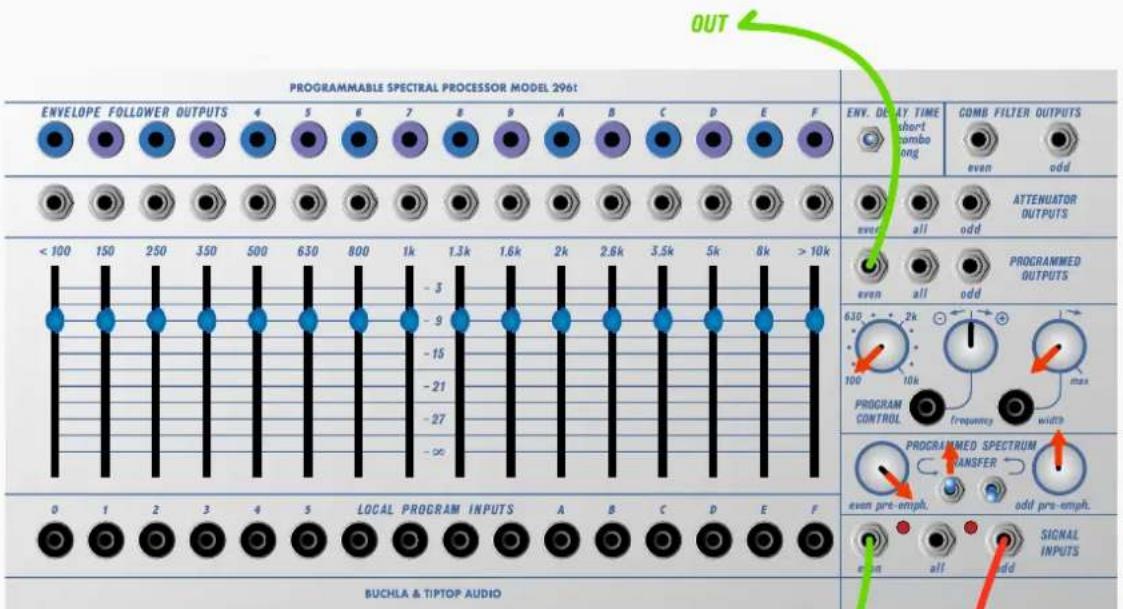
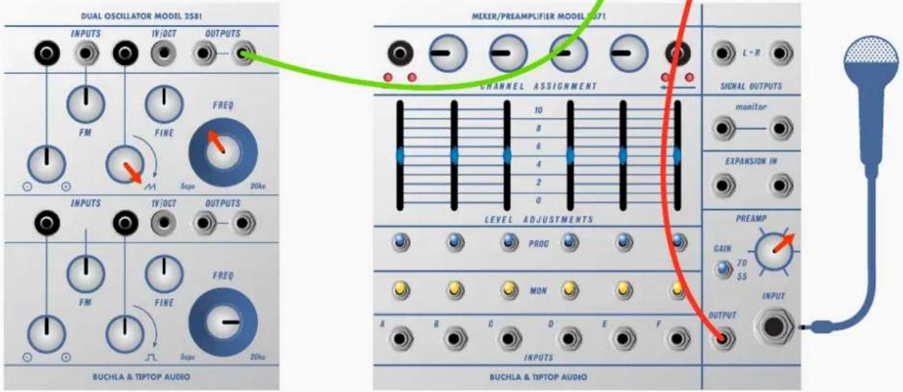
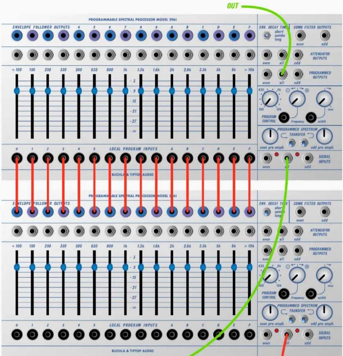
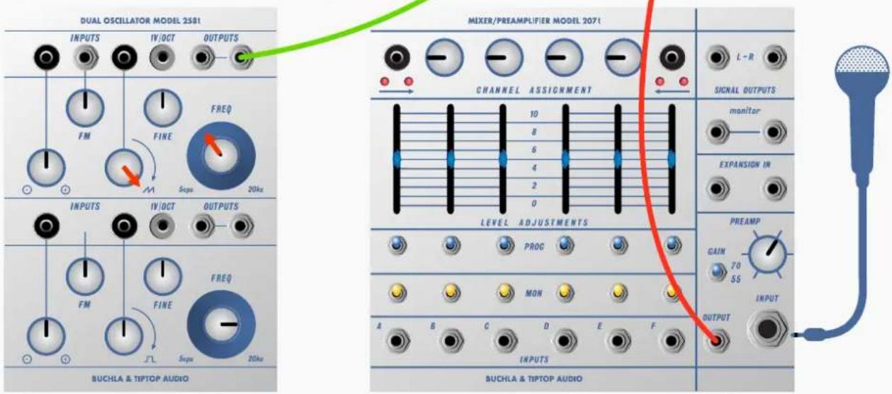
- PROGRAMMABLE SPECTRAL PROCESSOR - MODEL 296t
- Envelope Follower Outputs
- Env. Decay Time
- Comb Filter Outputs
- Individual Audio Outputs
- Attenuated Outputs
- Programmed Outputs
- Program Control
- Programmed Spectrum Transfer
- Please note:
- User Instructions:
- ATTENUATOR OUTPUTS
- CONTROL VOLTAGE OUTPUTS
- SPECTRAL BIAS
- LEDS
Brand : Tiptop Audio
Model : MODEL 296t
Category : Keyboard