
MCI-GM51 - Dash cam PAC - Free user manual and instructions
Find the device manual for free MCI-GM51 PAC in PDF.


| Product Type | Camera Interface Module (for adding cameras to factory 8" screen) |
| Brand | PAC |
| Model | MCI-GM51 |
| Compatibility | Vehicles with 8" screen, build codes IO5 and IO6; not compatible with IO3, IO4, IOA, IOB |
| Supported Cameras | Reverse camera, two blind spot cameras, one front view or trailer camera |
| Input Harness | Video Input harness BSM2-CEH |
| Power Harness | BSM3-PTH |
| LVDS Connectors | BSM1-LVDS |
| DIP Switches | 4 switches: Reverse camera type (factory/aftermarket), Model Year (2015-2016 or 2017-2019), others not used |
| Additional Features | Dynamic backup guide lines (aftermarket cameras), front camera triggers (speed up/down), turn signal activation for blind spot cameras, user interface for camera selection, installer setup |
| Installation Location | Behind factory screen, connected to HMI module |
| Included Accessories | Foam padding for rattle prevention |
| Dimensions | Approximately 3" x 2" x 1" (module only) |
| Weight | Approximately 0.2 lb (module only) |
| Power Source | Vehicle's factory 10-pin power harness (pass-through) |
| Maintenance | Keep dry, clean with soft cloth; avoid moisture |
Frequently Asked Questions - MCI-GM51 PAC
User questions about MCI-GM51 PAC
0 question about this device. Answer the ones you know or ask your own.
Ask a new question about this device
Download the instructions for your Dash cam in PDF format for free! Find your manual MCI-GM51 - PAC and take your electronic device back in hand. On this page are published all the documents necessary for the use of your device. MCI-GM51 by PAC.
USER MANUAL MCI-GM51 PAC
Introduction & Features
The MCI-GM51 will allow the addition of a reverse camera, two blind spot cameras, and one front view or trailer camera in vehicles equipped with the 8" screen.
Important Notes
- Compatible build codes: IO5 and IO6. Incompatible build codes: IO3, IO4, IOA, and IOB. Build codes can be found on a silver sticker either in the glove box or in the trunk near the spare tire well.
- If you change the DIP switch settings, you must disconnect and reconnect power for the change to take effect.
- If you are installing this interface strictly to add a reverse camera, please note that the blind spot inputs will need to be deactivated (depending on the vehicle) by entering the menu and manually disabling the inputs (see page 3 for details).
What's Included
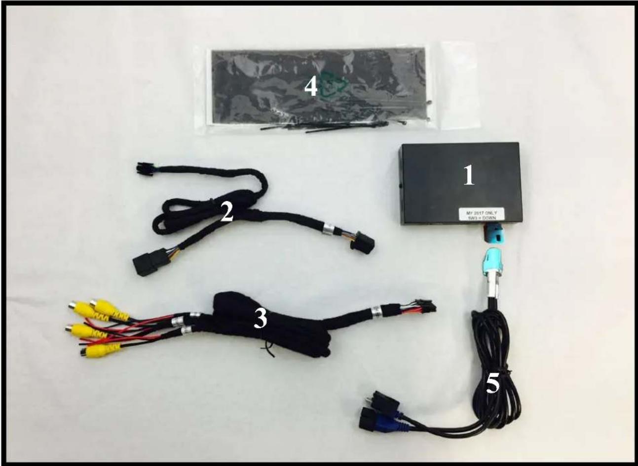
| 1 Module MCI-GM51 | |
| 2 Power Harness BSM3-PTH | |
| 3 Video Input harness BSM2-CEH | |
| 4 Foam Padding Miscellaneous | |
| 5 LVDS Connectors BSM1-LVDS |
DIP switches

Set DIP switches according to the descriptions below
| Not Used Reverse Camera Model Year Not Used | |||
| 1 2 3 4 | |||
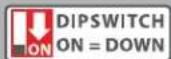
DIP switch Functions:
1. Not Used
Leave Up
2. Reverse Camera
- Up when vehicle has factory equipped reverse camera
- Down when you are installing an aftermarket reverse camera
3. Model Year
• Up for 2015-2016
• Down for 2017-2019
- Not Used
Leave Up
Installation Steps
- Set the DIP switches for your application based on the functions listed above. These DIP switches must be set to the proper configuration before connecting the interface to power.
- Remove the factory screen assembly and disconnect the factory 10-pin power harness (Fig. A).
Fig. A
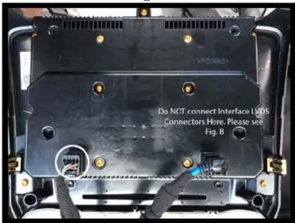
Fig. B

natural_image
Interior view of a car dashboard with visible electrical connectors and a magnified inset showing a hand holding a connector (no text or symbols present)Illustrations are typical and may not match exact vehicle details
- Connect the MCI-GM51's male power harness to the back of the factory screen assembly.
- Connect the factory harness into the female connector on the MCI-GM51 power harness.
- Locate the HMI module
a. Trucks and SUVs: The HMI is located in the upper portion of the glove box opening. If your vehicle does not have an HMI module then it is not compatible.
b. Passenger cars: The HMI module is located above the passenger kick panel. In the Chevy Volt, the HMI is directly behind the screen in the dash.
If your vehicle does not have an HMI module then it is not compatible.
- Disconnect the blue LVDS connector from the HMI module. (Fig. B)
- Connect the MCI-GM51's male LVDS harness to the HMI module.
- Connect the factory LVDS harness into the female LVDS connector on the MCI-GM51.
- Connect the power harness to the MCI-GM51 module.
- Connect the video harness to the MCI-GM51 module.
- Connect cameras and corresponding camera power wire outputs according to the chart on the right. If the vehicle is equipped with a factory reverse camera, then Input 3 can be used for a trailer cam or not at all. Secure and insulate any camera inputs and power wires not being used to prevent any contact with metal.
- If necessary, use the provided foam padding to insulate the module from any rattles before securing inside the dash cavity.
 |
| *This camera input is automatically activated when vehicle is in reverse gear, if DIP switch 2 is on. |
Operation
Accessing Trailer Camera (Input 3) when in Reverse
Once the vehicle is placed in reverse, and the reverse camera is visible, press and hold the "Back" button for three seconds (Fig. C) to access the Trailer Camera.
Accessing User Interface
Press and hold the "BACK" button (Fig. C) for three seconds to enter the camera menu. Press OK to accept the terms and continue. Use the touch screen to select the desired view. Press the "BACK" button to return to the previous screen.
Accessing Camera Setup
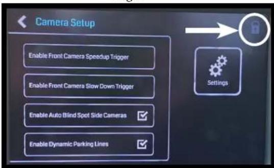
Press the gear icon in the top right corner to enter the camera setup menu (Fig. D). From here you can enable / disable MCI-GM51 functions (Fig. F).
- Enable Front Camera Speedup Trigger - When enabled, will trigger front camera when exiting reverse and turn off after 8 mph.
- Enable Front Camera Slowdown Trigger - When enabled, it will activate front camera when speed is reduced below 10 mph and steering wheel is turned more than 15 degrees. (This prevents unwanted front camera activation in stop and go traffic).
PLEASE NOTE: Enabling either front camera trigger will change the top middle icon on the user interface from "Trailer" to "Front" (Fig. E).
- Enable Turn Signal Cameras - When enabled, blind spot cameras will activate and display on the screen when the turn signals are activated.
- Enable Dynamic Backup Curves - When enabled, the MCI-GM51 will overlay dynamic backup guide lines over the reverse image (aftermarket cameras only).
Accessing Installer Setup
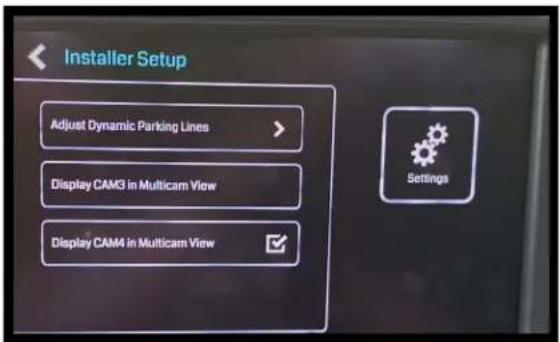
Press and hold the small lock icon in the top right corner of the camera setup menu to access installation settings (Fig. F).
See next page for available adjustments.
Fig. C

Fig. D

Fig. E

Fig. F
Illustrations are typical and may not match exact vehicle details
Operation (cont.)
Installer Setup
- Adjustments to the dynamic curve lines can also be made from this menu (aftermarket cameras only).
- Third camera in 3-way split view can be switched between inputs 3 and 4.
Fig. F
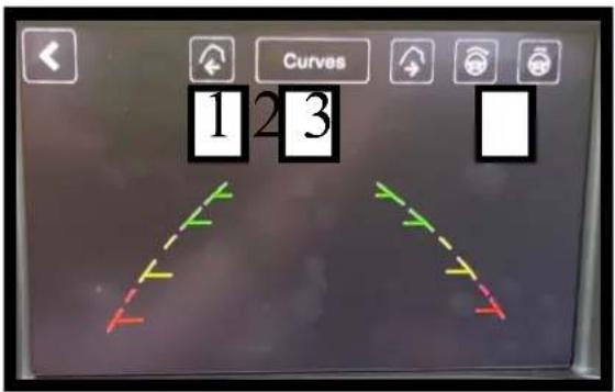
Adjustment of Dynamic Parking Lines
- These icons adjust the position of the lines on the screen.
- This icon changes the appearance of the lines.
- These icons changes the sensitivity of the movement of the lines when turning the steering wheel.

- Introduction & Features
- Important Notes
- What's Included
- DIP switches
- DIP switch Functions:
- Not Used
- Reverse Camera
- Model Year
- Installation Steps
- Illustrations are typical and may not match exact vehicle details
- Operation
- Accessing Trailer Camera (Input 3) when in Reverse
- Accessing User Interface
- Accessing Camera Setup
- Accessing Installer Setup
- Operation (cont.)
- Installer Setup
- Adjustment of Dynamic Parking Lines
Brand : PAC
Model : MCI-GM51
Category : Dash cam