PS580A-R2 - Power outlet Black Box - Free user manual and instructions
Find the device manual for free PS580A-R2 Black Box in PDF.


| Product Type | Rackmount Remote Power Manager |
| Brand | Black Box |
| Model | PS580A-R2 |
| Dimensions (W x D x H) | 19 x 4.6 x 1.75 inches (including rack brackets) |
| Height (Rack Units) | 1U |
| Input Voltage | 100–120 VAC, 50/60 Hz |
| Number and Type of Outlets | 4 NEMA 5-15 switched outlets |
| Maximum Load per Unit | 15A total |
| Network Interface | RJ-45 Ethernet (10BASE-T, half-duplex) |
| Serial Interface | DB9 RS-232 (DTE) |
| Default IP Address | 192.168.168.168 |
| Subnet Mask | 255.255.255.0 |
| User Interfaces | Web browser (JavaScript), text (Telnet, local terminal, modem) |
| Circuit Breaker | 15A |
| Operating Temperature | Up to 122°F (50°C) |
| Certifications | FCC Class A, UL, CE |
| Rack Mountable | Yes (brackets included) |
| Package Contents | Power manager, power cable, null-modem cable, quick start guide |
| Key Functions | Remote power management, individual outlet switching, reboot, power sequencing, password protection |
| Safety Notes | Shock hazard; do not service internally; disconnect if cord damaged |
| Cleaning | Wipe with dry cloth; avoid liquids |
Frequently Asked Questions - PS580A-R2 Black Box
User questions about PS580A-R2 Black Box
0 question about this device. Answer the ones you know or ask your own.
Ask a new question about this device
Download the instructions for your Power outlet in PDF format for free! Find your manual PS580A-R2 - Black Box and take your electronic device back in hand. On this page are published all the documents necessary for the use of your device. PS580A-R2 by Black Box.
USER MANUAL PS580A-R2 Black Box
Rackmount Remote Power Manager
Quick Start Guide
Use this guide to quickly set up your power manager.
Trademarks Used in this Manual
Black Box and the Double Diamond logo are registered trademarks of BB Technologies, Inc.
AT is a registered trademark of International Business Machines Corporation.
JavaScript is a registered trademark of Sun Microsystems, Inc.
Telnet is a trademark of Telnet Communications, Inc.
Any other trademarks mentioned in this manual are acknowledged to be the property of the trademark owners.
Disclaimer:
Black Box Network Services shall not be liable for damages of any kind, including, but not limited to, punitive, consequential or cost of cover damages, resulting from any errors in the product information or specifications set forth in this document and Black Box Network Services may revise this document at any time without notice.
We're here to help! If you have any questions about your application or our products, contact Black Box Tech Support at 724-746-5500 or go to blackbox.com and click on "Talk to Black Box."
You'll be live with one of our technical experts in less than 60 seconds.
Federal Communications Commission and Industry Canada Radio Frequency Interference Statements
This equipment generates, uses, and can radiate radio-frequency energy, and if not installed and used properly, that is, in strict accordance with the manufacturer's instructions, may cause interference to radio communication. It has been tested and found to comply with the limits for a Class A computing device in accordance with the specifications in Subpart B of Part 15 of FCC rules, which are designed to provide reasonable protection against such interference when the equipment is operated in a commercial environment. Operation of this equipment in a residential area is likely to cause interference, in which case the user at his own expense will be required to take whatever measures may be necessary to correct the interference.
Changes or modifications not expressly approved by the party responsible for compliance could void the user's authority to operate the equipment.
This digital apparatus does not exceed the Class A limits for radio noise emission from digital apparatus set out in the Radio Interference Regulation of Industry Canada.
European Union Declaration of Conformity
This equipment complies with the requirements of the European EMC Directive 89/336/EEC.
NOTE: All models comply with UL requirements. PS583A-R2 also complies with cUL.
WARNINGS AND CAUTIONS
Secure Racking
If secure racked units are installed in a closed or multi-unit rack assembly, they may require further evaluation by certification agencies. Consider the following items:
- The ambient temperature within the rack may be greater than the room ambient temperature. Installation should be such that the amount of airflow required for safe operation is not compromised. The maximum temperature for the equipment in this environment is 122^ F ( 50^ C).
- Install the unit so that it doesn't become unstable from uneven loading.
Input Supply
Check nameplate ratings to ensure that there is no overloading of supply circuits that could have an effect on overcurrent protection and supply wiring.
Grounding
Maintain reliable grounding of this equipment. Give particular attention to supply connections when connecting to power strips, rather than direct connections to the branch circuit.
Shock Hazard
Do not attempt to repair or service this device yourself. Internal components must be serviced by authorized personnel only.
Disconnect Power
If any of the following events occurs, immediately disconnect the unit from the outlet and contact Black Box at 724-746-5500.
- The power cord is frayed or damaged.
- Liquid has been spilled into the device or the device has been exposed to rain or water.
Quick Start Guide
Downloading the User Manual
To take full advantage of the complete range of features that the Remote Power Manager offers, we recommend that you read the user's manual after performing this quick start procedure.
The full user manual/installation guide can be downloaded from the Black Box Web site.
To download from the Web site:
- Go to www.blackbox.com
- Enter the part number in the search box:

- Click on the "Resources" tab on the product page, and select the document you wish to download.
If you have any trouble accessing the Black Box site to download the manual, you can contact our Technical Support at 724-746-5500 or info@blackbox.com.
Available Models and Specifications
| Model No. | Width | Depth | Height | Approvals |
| PS580A-R2 | 19" (48.3 cm), including rack brackets | 4.6" (11.68 cm) | 1.75" (4.5 cm),(1) rack unit | FCC, UL®, CE |
| PS581A-R2 | 19" (48.3 cm), including rack brackets | 4.6" (11.68 cm) | 1.75" (4.5 cm),(1) rack unit | FCC, UL, CE |
| PS568A-R2 | 19" (48.3 cm), including rack brackets 8.7" | (22.1 cm) 3.5" (8.9 cm),(2) rack units | cm), | FCC, UL, CE |
| PS582A-R2 | 19" (48.3 cm), including rack brackets 8.7" | (22.1 cm) 3.5" (8.9 cm),(2) rack units | cm), | FCC, UL, CE |
| PS569A-R2 | 19" (48.3 cm), including rack brackets 8.7" | (22.1 cm) 3.5" (8.9 cm),(2) rack units | cm), | FCC, UL, CE |
| PS583A-R2 | 19" (48.3 cm), including rack brackets 7" (17.8 cm) 3.5" (8.9 cm),(2) rack units | (22.1 cm) 3.5" (8.9 cm),(2) rack units | cm), | UL, cUL, CE,FCC Class A |
Hardware Description
Rear Panel
The Rackmount Remote Power Manager (PS580A-R2) is pictured in Figure 1. The PS581A-R2 (not pictured) has four 208- to 240-VAC IEC-320-C13 AC outlets instead of four 100- to 120-VAC, 50- to 60-Hz NEMA 5-15 AC outlets. Back-panel connectors, indicators, and switches are described in Table 1. The numbers in the figures correspond to the numbers in the table.

Figure 1. Rackmount Remote Power Manager (PS580A-R2) back panel.
Table 1. Back-panel components.
| Number Component Description | ||
| 1 | Network port | An RJ-45 Ethernet port for connection to your TCP/IP network. The default IP address is 192.168.168.168. For more information, refer to Section 4.3.4 in the user's manual. |
| 2 | Activity indicator | Flashes to indicate activity at the network port. |
| 3 | Ready indicator | Flashes continuously when the power manager is ready to receive commands. |
| 4 COM /RS-232 | port | This DB9 COM/RS-232 (DTE) serial port connects to a local terminal or external modem, as described in Section 3.3 of the user's manual. |
| 5 | Default button | This button resets the unit to default parameters or manually toggles all plugs on or off.Default parameters: With the master I/O switch (master power switch) set to the Off position, press and hold the default button, then set the master I/O switch to the On position and release the default button. All menu-defined parameters will reset to default values.Manual plug toggle: Press the default button and and hold it down for three seconds. All power outlets will be toggled on or off. |
| 6 Switched plugs | and plug | Four 100- to 120-VAC, NEMA 5-15 or 208- to indicators 240-VAC IEC-320-C13 outlets that can be switched on, off, or rebooted in response to user commands. The outlets have indicator lights and support 15 or 10 amps total load. |
| 7 Master power | switch | This switch turns on the power to the power manager itself. The switch must be on for the power manager to function. This switch is not used to set the on/off status of the switched outlets. |
| 8 | Power inlet | An IEC-320 AC inlet (with attached cable keeper) that supplies AC power for the power manager's command functions and the switched plugs. |
| 9 | Circuit breaker | A 15-amp or 10-amp circuit breaker supplies power to the outlets. |
Front Panel
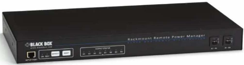
The Rackmount Remote Power Manager's front panel has two indicators. Located from left to right are LEDs for Power On and Sys Rdy (flashes when the system is ready).
Hardware Installation
- Connect the power cable (included) to the Rackmount Remote Power Manager's power inlet. Connect the other end of the cable(s) to an appropriate power outlet (100- to 115-VAC for the PS580A-R2; 208- to 230-VAC for the PS581A-R2). Place the master power switch in the "On" position. After a brief pause, the plug indicators should switch on in sequence, indicating that power is on.
CAUTION: Review the safety precautions listed on page 5.
- Make sure the Ready indicator is blinking. This means the Rackmount Remote Power Manager is operating properly and is ready to receive commands.
- To initiate switching operations or select configuration parameters, you must issue commands to the Rackmount Remote Power Manager via either the network port or the COM/RS-232 port. It's optional to connect to both the network port and the COM/RS-232 port.
a) Network Port: To communicate with the Rackmount Remote Power Manager via the network, connect your 10BASE-T or 100BASE-T network interface to the Remote Power Manager's network port. For more information on network port connections, please refer to Section 3.4 in the user's manual.
NOTE: The Rackmount Remote Power Manager features a half-duplex, 10BASE-T interface. When connecting the manager to a 100BASE-T interface, most router/switches will autosense to determine if the device is 100BASE-T or 10BASE-T, and then configure the network interface accordingly. If your router/switch does not autosense, the manager's network interface port must be manually set to half-duplex, 10BASE-T.
b) COM/RS-232 Port: To communicate with the Rackmount Remote Power Manager via a local PC, use the supplied null-modem cable to connect your PC COM/RS-232 port to the Remote Power Manager's COM/RS-232 port. For more information, please refer to Section 3.3 in the user's manual.
Or, connect an external modem to the COM/RS-232 port (see below).
External modem: Use a standard AT® to modem cable to connect an external modem to the Rackmount Remote Power Manager's COM/RS-232 port.
NOTE: When the Rackmount Remote Power Manager is shipped from the factory, COM/RS-232 port parameters are set as follows: 9600 bps, 8 data bits, one stop bit, and no parity. Although these parameters can be easily redefined, we recommend that you configure your communications program to accept these default parameters.
Communicating with the Rackmount Remote Power Manager
The Rackmount Remote Power Manager offers two different user interfaces: a Web-browser interface and a text interface. The Web-browser interface allows you to contact the Remote Power Manager via a TCP/IP network using a standard JavaScript® enabled Web browser (such as Internet Explorer). The text interface consists of a series of ASCII text menus, accessible via a TCP/IP network, local PC, or external modem.
NOTE: The Rackmount Remote Power Manager has a default IP address (192.168.168.168) and subnet mask (255.255.255.0). If you are contacting the Rackmount Remote Power Manager from a node on the same subnet, this allows initial network access to the operating mode without first setting up the unit's network parameters. When attempting to access the Rackmount Remote Power Manager from a node that is not on the same subnet, please refer to Section 4.3.4 in the user's manual for further instructions.
- Access the operating mode: This procedure differs slightly, depending on whether you're contacting the Rackmount Remote Power Manager via the Web-browser interface or the text interface.
a) From the Web-browser interface, start your JavaScript enabled Web browser. Enter the Rackmount Remote Power Manager's default IP address (http://192.168.168.168) in your browser's address bar, then press [Enter]. A password prompt will be displayed. Since at this point the user name and password have not yet been defined, simply click on OK without typing in a user name or password. The Rackmount Remote Power Manager's Plug Status screen appears as shown in Figure 2.
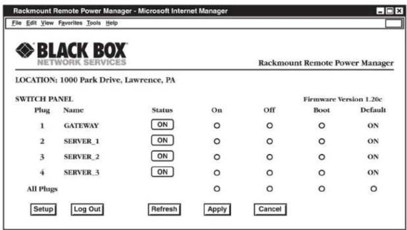
Figure 2. Plug Status screen—Web-browser interface for PS580A-R2 and PS581A-R2.
b) From the text interface:
i. Via Telnet™: Start your Telnet program, then Telnet to the Rackmount Remote Power Manager's default IP address (192.168.168.168). The Rackmount Remote Power Manager's Plug Status screen (Figure 3) appears.
ii. Via Local PC: Start your communications program (for example, HyperTerminal) and press [Enter]. The Remote Power Manager's Plug Status screen appears (Figure 3).
iii. Via modem: Use your communications program to dial the number for the phone line that is connected to your external modem. To communicate with the unit via modem, you must first access the command mode via network or local PC, and use the Serial Parameters menu to set the port mode to modem.
| Rackmount Remote Power Manager v1.41h Site ID: (undefined) | |||||
| Plug | Name | Password | Status | Boot/Seq.Delay | Default |
| 1 | (undefined) | (undefined) | ON | 0.5 Secs | ON |
| 2 | (undefined) | (undefined) | ON | 0.5 Secs | ON |
| 3 | (undefined) | (undefined) | ON | 0.5 Secs | ON |
| 4 | (undefined) | (undefined) | ON | 0.5 Secs | ON |
| "/H" for help. RPM> | |||||
Figure 3. Plug Status screen—text interface for PS580A and PS581A.
NOTE: The default communications parameters for the console port are 9600 bps, no parity, 8 data bits, and 1 stop bit.
- Perform the following tests to make sure that the Rackmount Remote Power Manager is responding to commands.
a) Reboot outlet: If you are communicating with the Rackmount Remote Power Manager via the Web-browser interface, select the button in the "Boot" column for plug 1, then click Apply. If you are operating the Remote Power Manager via the text interface, type /BOOT 1 and press [Enter]. The status indicator for plug 1 should go off, pause for a moment, and then go back on (indicating that the boot cycle has been successfully completed).
b) Switch outlet off: From the Web-browser interface, select the button in the "Off" column for plug 1, then click Apply. From the text interface, type /OFF 1 and press [Enter]. The status indicator for plug 1 should go off, indicating that the command has been successfully completed. Leave plug 1 in the "Off" state, then proceed to the next step.
c) Switch outlet on: From the Web-browser interface, select the button in the "On" column for plug 1, then click Apply. From the text interface, type /ON 1 and press [Enter]. The status indicator for plug 1 should then go back on, indicating that the command has been successfully completed.
- When you have finished communicating with the Rackmount Remote Power Manager, always log off by issuing the appropriate Rackmount Remote Power Manager command rather than simply closing your Telnet or communications program. Logging off with the proper command ensures that the Rackmount Remote Power Manager has completely exited from operating mode and is not waiting for the inactivity timeout to elapse before allowing additional connections.
For the Web-browser interface, click on the Log Out button.
For the text interface, type /X and press [Enter].
Please proceed to Chapters 3 and 4 in the user's manual for complete installation and configuration procedures.
Black Box Tech Support: FREE! Live. 24/7.
Tech support the way it should be.

natural_image
Close-up portrait of a smiling man with a headset, no visible text or symbolsGreat tech support is just 60 seconds away at 724-746-5500 or blackbox.com.

BLACK BOX®
About Black Box
Black Box provides an extensive range of networking and infrastructure products. You'll find everything from cabinets and racks and power and surge protection products to media converters and Ethernet switches all supported by free, live 24/7 Tech support available in 60 seconds or less.
© Copyright 2015. Black Box Corporation. All rights reserved. Black Box ^® and the Double Diamond logo are registered trademarks of BB Technologies, Inc. Any third-party trademarks appearing in this manual are acknowledged to be the property of their respective owners.
PS580A-R2 Quick Start Guide, version 1
- Rackmount Remote Power Manager
- Quick Start Guide
- Trademarks Used in this Manual
- Disclaimer:
- Federal Communications Commission and Industry Canada Radio Frequency Interference Statements
- European Union Declaration of Conformity
- WARNINGS AND CAUTIONS
- Secure Racking
- Input Supply
- Grounding
- Shock Hazard
- Disconnect Power
- Downloading the User Manual
- To download from the Web site:
- Available Models and Specifications
- Hardware Description
- Rear Panel
- Front Panel
- Hardware Installation
- Communicating with the Rackmount Remote Power Manager
- Black Box Tech Support: FREE! Live. 24/7.
- BLACK BOX®
- About Black Box
Brand : Black Box
Model : PS580A-R2
Category : Power outlet