
ThinkSystem DE6000F - Disk array LENOVO - Free user manual and instructions
Find the device manual for free ThinkSystem DE6000F LENOVO in PDF.


| Product Type | Disk Array (Storage System) |
| Brand | Lenovo |
| Model | ThinkSystem DE6000F |
| Form Factor | 2U Rackmount |
| Drive Bays | 24 x 2.5" SAS/SATA/NVMe (all-flash) |
| Controller | Dual active/active controllers |
| Cache Memory | Up to 128 GB per controller (NV cache) |
| Host Interfaces | 8/16/32 Gbps Fibre Channel, 10/25 Gbps iSCSI, 12 Gbps SAS |
| Max Capacity (raw) | Up to 368 TB with 15.36 TB SSDs |
| Dimensions (W x D x H) | 482 x 640 x 87 mm (19" x 25.2" x 3.4") |
| Weight (fully loaded) | Approximately 28 kg (61.7 lbs) |
| Power Supply | Dual redundant, 800W (Platinum) |
| Input Voltage | 100-240 V AC, 50/60 Hz |
| RAID Levels | 0, 1, 5, 6, 10, 50, 60 |
| Key Features | All-flash performance, data deduplication, compression, thin provisioning, snapshots, replication |
| Management | Lenovo Storage Manager, CLI, REST API |
| Cooling | Hot-swappable fan modules (N+1 redundant) |
| Operating Temperature | 5°C to 40°C (41°F to 104°F) |
| Humidity (non-condensing) | 10% to 90% |
| Safety Certifications | UL, CE, FCC, RoHS, REACH |
| Warranty | 3 years (optional extension) |
| Spare Parts | Controllers, power supplies, fans, drives, interface cards (all hot-swappable) |
| Maintenance | Replace failed components online; firmware upgrade via Storage Manager |
| Cleaning | Wipe exterior with dry cloth; avoid liquids; ensure proper airflow |
| Disposal | Recycle through e-waste programs; wipe data before disposal |
Frequently Asked Questions - ThinkSystem DE6000F LENOVO
User questions about ThinkSystem DE6000F LENOVO
0 question about this device. Answer the ones you know or ask your own.
Ask a new question about this device
Download the instructions for your Disk array in PDF format for free! Find your manual ThinkSystem DE6000F - LENOVO and take your electronic device back in hand. On this page are published all the documents necessary for the use of your device. ThinkSystem DE6000F by LENOVO.
USER MANUAL ThinkSystem DE6000F LENOVO
Hardware Installation and Maintenance Guide for 2U and 4U Enclosures

natural_image
Hexagonal grid pattern with colored hexagons (black, green, blue, orange, red, yellow) arranged in a curved sequence (no text or symbols)Machine Types: DE2000H (7Y70, 7Y71), DE4000H (7Y74, 7Y75, 7Y77), DE4000F (7Y76), DE6000H (7Y78, 7Y80), DE6000F (7Y79), DE120S (7Y63), DE240S (7Y68), and DE600S (7Y69)
Note
Before using this information and the product it supports, be sure to read and understand the safety information and the safety instructions, which are available at:
http://thinksystem.lenovofiles.com/help/topic/safety_documentation/pdf_files.html
In addition, be sure that you are familiar with the terms and conditions of the Lenovo warranty for your server, which can be found at:
http://datacentersupport.lenovo.com/warrantylookup
First Edition (June 2019)
© Copyright Lenovo 2019.
LIMITED AND RESTRICTED RIGHTS NOTICE: If data or software is delivered pursuant to a General Services
Administration (GSA) contract, use, reproduction, or disclosure is subject to restrictions set forth in Contract No. GS-35F-05925.
Contents
Safety....iii
Chapter 1. Introduction ..... 1
DE Series hardware overview ..... 1
Front view 2
Rear view 3
Specifications of DE2000 series. ..... 10
Specifications of DE4000 series. ..... 14
Specifications of DE6000 series. ..... 20
Specifications of drive shelves ..... 26
Management software overview ..... 30
Chapter 2. System setup and configuration....35
Initial Setup 35
Cabling your storage system ..... 36
Overview and requirements ..... 36
Host cabling ..... 37
Drive shelf cabling 38
Power cabling. 40
Hot adding a drive shelf ..... 40
Ethernet cabling for a management station . . 45
Windows express configuration ..... 46
Decide whether to use this Express method . . 47
Understand the workflow ..... 49
Verify the Windows configuration is supported....49
Configure management port IP addresses .. 50
Configure the multipath software ..... 50
Install ThinkSystem Storage Manager for SMcli and Host Context Agent (HCA). . . . 51
Access ThinkSystem System Manager and use the Setup wizard ..... 51
Perform FC-specific tasks ..... 53
Perform iSCSI-specific tasks ..... 55
Perform SAS-specific tasks ..... 60
Discover storage on the host ..... 62
Configure storage on the host ..... 63
Verify storage access on the host ..... 63
VMware express configuration ..... 64
Deciding whether to use this Express method....64
Understand the workflow ..... 66
Verify the VMware configuration is supported....66
Configure management port IP addresses .. 67
Configure the multipath software ..... 67
Install ThinkSystem Storage Manager for
SMcli and Host Context Agent (HCA). . . . . 67
Access ThinkSystem System Manager and use the Setup wizard ..... 6
Perform FC-specific tasks ..... 69
Perform iSCSI-specific tasks ..... 71
Perform SAS-specific tasks ..... 76
Discover storage on the host ..... 78
Configure storage on the host ..... 79
Verify storage access on the host ..... 79
Linux express configuration ..... 79
Decide whether to use this Express method . . 79
Fibre Channel Express Setup. . . . . . . 80
SAS Express Setup 88
iSCSI Express Setup ..... 94
Chapter 3. Hardware replacement procedures ..... 105
Batteries 105
Overview and requirements ..... 105
Replace battery 106
Controllers....114
Overview and requirements ..... 114
Replace a controller 115
Power-fan canisters ..... 128
Overview and requirements ..... 128
Replace power supply (12-drive or 24-drive)....129
Canister....132
Overview and requirements ..... 132
Replace power canister ..... 135
Overview and requirements ..... 141
Replace drive (12-drive, 24-drive or 60-drive)....143
Host interface cards ..... 150
Overview and requirements ..... 150
Add host interface cards 154
Upgrade host interface card ..... 163
Replace host interface card ..... 173
Host port protocol....182
Overview and requirements ..... 182
Change host protocol. 187
Chapter 4. System upgrade .....199
What's New in DE Series software version
11.50.2....199
Additional information....199
Upgrade ThinkSystem SAN OS software ..... 201
Overview and upgrade considerations . . . . 201
Upgrade software and firmware for multiple controllers....205
Upgrade drive firmware ..... 208
Chapter 5. System monitoring . . . . 213
Understanding the controller LEDs and displays. 213
LEDs on the rear of controllers ..... 214
LEDs on the operator display panel ..... 216
LEDs on the drives ..... 220
LEDs on the drive drawer ..... 221
LEDs on the IOMs ..... 223
LEDs on the power-fan canister ..... 224
LEDs on the power canister ..... 224
LEDs on the fan canister ..... 225
Seven-segment display overview ..... 227
Critical Events Reference ..... 231
Appendix A. Getting help and technical assistance .....321
Appendix B. Notices....323
Trademarks 324
Important notes....324
Particulate contamination ..... 324
Telecommunication regulatory statement ..... 325
Electronic emission notices ..... 325
Taiwan BSMI RoHS declaration. . . . . . . 326
Taiwan import and export contact information . . . 326
Index . . . . . . . . . . . . . . . . . . . . . . . . . . . . . . . . . . . . . . . 327
Safety
Before installing this product, read the Safety Information.
This chapter provides a brief introduction to the ThinkSystem DE series products. ThinkSystem DE series are dedicated for high-bandwidth applications such as big data analytics, video-surveillance, and disk-based backup that need simple, fast, and reliable SAN storage.
A storage array includes shelves, controllers, drives, software, and firmware. The array can be installed in a rack or cabinet, with customizable hardware for two controllers, in a 12-, 24-, or 60-drive shelf. You can connect the storage array to a SAN from multiple interface types and to a variety of host operating systems.
DE Series hardware overview
The ThinkSystem DE series storage arrays are available in several configurations and models. This guide provides installation and maintenance information for 2U* and 4U* models.
Table 1. DE series family
| Family Model Machine | Type Form factor Drives | |||
| DE2000 DE2000H 7Y70 | 2U 12 | |||
| DE2000H 7Y71 2U 24 | ||||
| DE4000 DE4000H 7Y74 | 2U 12 | |||
| DE4000H 7Y75 2U 24 | ||||
| DE4000F 7Y76 2U 24 | ||||
| DE4000H 7Y77 4U 60 | ||||
| DE6000 DE6000H 7Y78 | 2U 24 | |||
| DE6000F 7Y79 2U 24 | ||||
| DE6000H 7Y80 4U 60 | ||||
| Drive shelves(expansion shelves) | DE120S | 7Y63 2U 12 | ||
| DE240S | 7Y68 2U 24 | |||
| DE600S | 7Y69 4U 60 |
Note: *U is rack unit, defined as 44.45 mm (1.75 inches) high.
Front view
This topic provides information about the front view of 2U and 4U models. Front view of models with the same drive bays is the same.
Front view of 2U models
The following illustration shows the front view of DE4000H (12 drives). Front view of DE2000H (12 drives) or DE120S is the same.

Figure 1. Front view of models with 12 drive bays
1 Operator display panel
2 drive bays
The following illustration shows the front view of DE2000H (24 drives). Front view of DE4000H (24 drives), DE4000F (24 drives), DE6000H (24 drives), DE6000F (24 drives), or DE240S is the same.

natural_image
Front view of a black Lenovo rack with ventilation slots and labeled ports (no text or symbols on the rack itself)Figure 2. Front view of models with 24 drive bays
1 Operator display panel
2 drive bays
For information about the LEDs on the operator display panel, see "LEDs on the operator display panel" on page 216.
For information about the LEDs on drives, see "LEDs on the drives" on page 220.
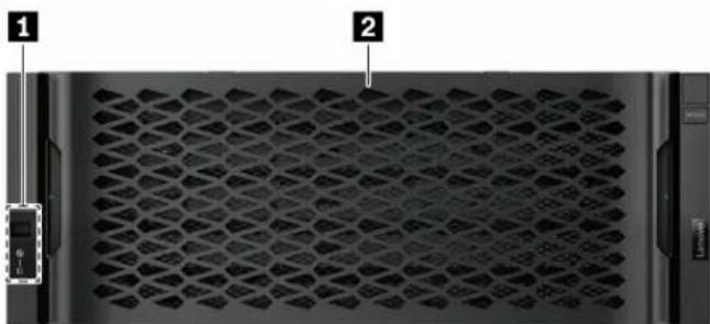
Front view of 4U models
The following illustration shows the front view of DE4000H (60 drives) and DE6000H (60 drives). Front view of DE4000H, DE6000H, and DE600S (60 drives) is the same.
natural_image
Front view of a server rack with hexagonal mesh pattern and labeled ports (no readable text or symbols)Figure 3. Front view of models with 60 drives
| 1 Operator display panel | 2 Drive bays |
For information about the LEDs on the operator display panel, see “LEDs on the operator display panel” on page 216.
For information about the LEDs on the drive drawer, see "LEDs on the drive drawer" on page 221.
Rear view
The rear of the system provides access to several connectors and components, including the power supplies and various connectors. This topic provides information about the rear view of 2U and 4U models.
Rear view of DE2000 series (2U)
The following illustration shows the rear view of a dual DE2000 controller shelf, each controller with a two-port host interface card (HIC). Depending on the configuration, your system might look slightly different from the illustration.
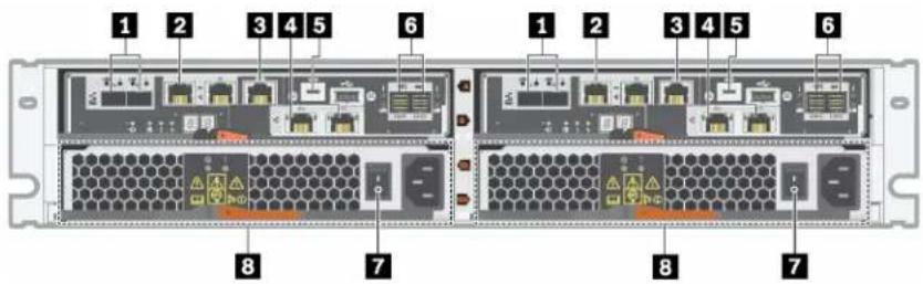
Figure 4. Rear view of DE2000 series (2U)
| 1 Baseboard host ports* | 2 1Gb Ethernet management port* |
| 3 RJ45 console port | 4 HIC host ports* |
| 5 Micro-B USB console port SAS expansion ports | |
| 7 Power supply switch | 8 Power-fan canister |
Notes:
- ①: Depending on the configuration, the baseboard host ports can be two 10Gb iSCSI optical ports or 16Gb Fiber Channel (FC) ports.
- 2: There are two Ethernet ports. The P1 port is the 1Gb Ethernet management port. The P2 port is reserved for Lenovo technical support.
- : Depending on the configuration, the optional HIC host ports can be two 10Gb Base-T ports or 12Gb SAS ports.
For information about the LEDs on the rear view, see “LEDs on the rear of controllers” on page 214 and “LEDs on the power-fan canister” on page 224.
Rear view of DE4000 series (2U)
The following illustration shows the rear view of a dual DE4000 controller shelf (2U), each controller with a four-port HIC. Depending on the configuration, your system might look slightly different from the illustration.

Figure 5. Rear view of DE4000 series (2U)
| 1 Baseboard host ports* | 2 1Gb Ethernet management port* |
| 3 RJ45 console port | 4 HIC host ports (optional)* |
| 5 Micro-B USB console port SAS expansion ports | |
| 7 Power supply switch | 8 Power-fan canister |
Notes:
- 1: Depending on the configuration, the baseboard host ports can be two 10Gb iSCSI optical ports or 16Gb FC ports.
- 7: There are two Ethernet ports. The P1 port is the 1Gb Ethernet management port. The P2 port is reserved for Lenovo technical support.
- ①: Depending on the configuration, the optional HIC host ports can be four 12Gb SAS ports, 10Gb iSCSI optical ports, 16Gb FC ports, 10/25Gb iSCSI ports, or 32Gb FC ports.
For information about the LEDs on the rear view, see “LEDs on the rear of controllers” on page 214 and “LEDs on the power-fan canister” on page 224.
Rear view of DE6000 series (2U)
The following illustration shows the rear view of a dual DE6000 controller shelf (2U), each controller with a four-port HIC. Depending on the configuration, your system might look slightly different from the illustration.

Figure 6. Rear view of DE6000 series (2U)
| 1 Baseboard host ports* RJ45 console port | |
| 3 SAS expansion ports HIC host ports (optional)* | |
| 5 1Gb Ethernet management port* | 6 Micro-B USB console port |
| 7 Power supply switch | 8 Power-fan canister |
Notes:
- ①: Depending on the configuration, the baseboard host ports can be two 10Gb iSCSI optical ports or 16Gb FC ports.
- 2: There are two Ethernet ports. The P1 port is the 1Gb Ethernet management port. The P2 port is reserved for Lenovo technical support.
- 4: Depending on the configuration, the optional HIC host ports can be four 12Gb SAS ports, 10/25Gb iSCSI optical ports, or 32Gb FC ports.
For information about the LEDs on the rear view, see “LEDs on the rear of controllers” on page 214 and “LEDs on the power-fan canister” on page 224.
Rear view of DE120S and DE240S (2U)
The following illustration shows the rear view of DE120S and DE240S.
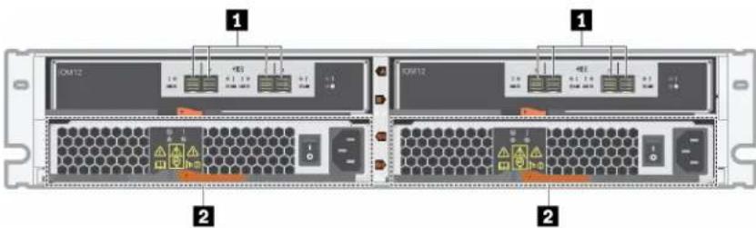
Figure 7. Rear view of DE120S and DE240S (2U)
| 1 SAS ports | 2 power-fan canister |
Note: For information about the LEDs on the rear view, see “LEDs on the IOMs” on page 223 and “LEDs on the power-fan canister” on page 224.
Rear view of DE4000H (4U)
The following illustration shows the rear view of a dual DE4000H controller shelf (4U), each controller with a four-port HIC. Depending on the configuration, your system might look slightly different from the illustration.

Figure 8. Rear view of DE4000H (4U)
| 1 Fan canisters Baseboard host ports* | |
| 3 1Gb Ethernet management ports* | 4 RJ45 console ports |
| 5 Micro-B USB console ports | 6 Power canisters |
| 7 Power supply switches | 8 HIC host ports (optional)* |
| 9 SAS expansion ports |
Notes:
- 7: Depending on the configuration, the onboard host interface ports can be two 10Gb iSCSI optical ports or 16Gb FC ports.
- There are four Ethernet ports. The P1 ports are the 1Gb Ethernet management ports. The P2 ports are reserved for Lenovo technical support.
- 3: Depending on the configuration, the optional HIC ports can be four 10Gb iSCSI optical ports, 12Gb SAS ports, 16Gb FC ports, 25Gb iSCSI optical ports, or 32Gb FC ports.
For information about the LEDs on the rear view, see “LEDs on the rear of controllers” on page 214, “LEDs on the power canister” on page 224, and “LEDs on the fan canister” on page 225.
Rear view of DE6000H (4U)
The following illustration shows the rear view of a dual DE6000H controller shelf (4U), each controller with a four-port HIC. Depending on the configuration, your system might look slightly different from the illustration.
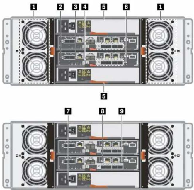
Figure 9. Rear view of DE6000H (4U)
| 1 Fan canisters Baseboard host ports* | |
| 3 RJ45 console ports | 4 SAS expansion ports |
| 5 Power canisters | 5 HIC host ports (optional)* |
| 7 Power supply buttons | 3 1Gb Ethernet management ports* |
| 9 Micro-B USB console ports |
Notes:
- 2: Depending on the configuration, the onboard host interface ports can be two 10Gb iSCSI optical ports or 16Gb FC ports.
- 8: Depending on the configuration, the optional HIC ports can be four 12Gb SAS ports, 10/25Gb iSCSI optical ports, 32Gb FC ports.
- 3: There are four 1Gb Ethernet ports. The P1 ports are the 1Gb Ethernet management port. The P2 ports are reserved for Lenovo technical support.
For information about the LEDs on the rear view, see “LEDs on the rear of controllers” on page 214, “LEDs on the power canister” on page 224, and “LEDs on the fan canister” on page 225.
Rear view of DE600S (4U)
The following illustration shows the rear view of DE600S.
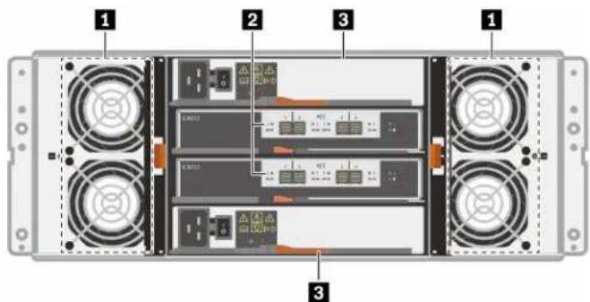
Figure 10. Rear view of DE600S (4U)
| 1 Fan canisters | 2 SAS expansion ports |
| 3 Power canisters |
Note: For information about the LEDs on the rear view, see “LEDs on the IOMs” on page 223, “LEDs on the power canister” on page 224, and “LEDs on the fan canister” on page 225
Specifications of DE2000 series
The following information is a summary of specifications of the DE2000 series.
- "Specifications of DE2000H (12 drives)" on page 10
- "Specifications of DE2000H (24 drives)" on page 12
Note: The following values can vary depending on your model and configuration.
Specifications of DE2000H (12 drives)
| Specification DE2000H (12 drives) | |
| Dimension | Form factor: 2UHeight: 87 mm (3.43 inches)Width: 448 mm (17.64 inches)Depth: 536 mm (21.10 inches) |
| Weight | 28.78 kg (63.45 lb) |
| Processor | Two 64-bit 2-core, Broadwell DE 2.20 GHz processors |
| System memory 16 GB (8 GB per controller) | |
| Supported drives | 3.5-inch NL-SAS drives2.5-inch SAS SSD/HDD drives in a 3.5-inch adapter tray |
| System Maximums and Limits | Max. raw capacity: 576 TBMax. HDD drive count: 48Max. SSD drive count: 48Max. expansion shelf count: 3Max. volume count: 512Max. drives per disk pool: 48Max. disk pool volumes: 512Max. Vol size for a disk pool volume (TB): 857Max. disk pools: 20Max partitions: 128Max volumes per partition: 256SSD Read Cache -> Maximum system-wide capacity allowed: 3,725.290 GiBMax destaging cache-to-flash size: 8 GB |
| Interfaces Available with the following interfaces:16Gb Fibre Channel12Gb SAS10Gb iSCSI optical10Gb iSCSI BaseT (RJ-45) | |
| System clearance dimension The clearance needed for proper ventilation and heat dissipation is as follows:Front: 813 mm (32.02 inches)Rear: 610 mm (24.02 inches) | |
| Power input Input power voltage:Low range: 100–120 V acHigh range: 200–240 V ac | |
| Acoustic noise | Sound power: 6.6 bels maximum |
| Environment requirements | Air temperature:- Operating: 10°C to 40°C (50°F to 104°F)- Storage or shipping: -40°C to 70°C (-40°F to 158°F)Relative humidity:- Operating: 20%–80%- Storage: 5%–95%- Shipping: 10%–95%Altitude range:- Operating: 0 m to 3048 m (0 ft to 10000 ft)- Storage: -305 m to 12 192 m (-1000 ft to 39990 ft)Note:If you plan to operate a system at an altitude between 3280 ft to 9842 ft (1000 m to 3000 m) above sea level, lower the environmental temperature 3.1°F (1.7°C) for every 3280 ft (1000 m) above sea level. |
Specifications of DE2000H (24 drives)
| Specification DE2000H (24 drives) | |
| Dimension | Form factor: 2UHeight: 85 mm (3.35 inches)Width: 448 mm (17.64 inches)Depth: 482.6 mm (19.0 inches) |
| Weight | 24.59 kg (54.21 lb) |
| Processor Two 64-bit 2-core, Broadwell DE 2.20 GHz processors | |
| System memory 16 GB (8 GB per controller) | |
| Supported drives 2.5-inch SAS | SSD/HDD drives |
| System Maximums and Limits | Max. raw capacity: 1.47 PBMax. HDD drive count: 96Max. SSD drive count: 96Max. expansion shelf count: 3Max. volume count: 512Max. drives per disk pool: 96Max. disk pool volumes: 512Max. Vol size for a disk pool volume (TB): 789Max. disk pools: 20Max partitions: 128Max volumes per partition: 256SSD Read Cache -> Maximum system-wide capacity allowed: 3,725.290 GiBMax destaging cache-to-flash size: 8 GB |
| Interfaces Available with the following interfaces:16Gb Fibre Channel12Gb SAS10Gb iSCSI optical10Gb iSCSI BaseT (RJ-45) | |
| System clearance dimension The clearance needed for proper ventilation and heat dissipation is as follows:Front: 813 mm (32.02 inches)Rear: 610 mm (24.02 inches) | |
| Power input Input power voltage:Low range: 100–120 V acHigh range: 200–240 V ac | |
| Acoustic noise | Sound power: 6.8 bels maximum |
| Environment requirements | Air temperature:- Operating: 10^ to 40^ ( 50^ to 104^ )- Storage or shipping: -40^ to 70^ ( -40^ to 158^ )Relative humidity:- Operating: 20%-80% - Storage: 5%-95% - Shipping: 10%-95% Altitude range:- Operating: 0 m to 3048 m (0 ft to 10000 ft)- Storage: -305 m to 12 192 m ( -1000 ft to 39990 ft)Note:If you plan to operate a system at an altitude between 3280 ft to 9842 ft (1000 m to 3000 m) above sea level, lower the environmental temperature 3.1^ ( 1.7^ ) for every 3280 ft (1000 m) above sea level. |
Specifications of DE4000 series
The following information is a summary of specifications of the DE4000 series.
- "Specifications of DE4000H (12 drives)" on page 14
- "Specifications of DE4000H or DE4000F (24 drives)" on page 16
- "Specifications of DE4000H (60 drives)" on page 18
Note: The following values can vary depending on your model and configuration.
Specifications of DE4000H (12 drives)
| Specification DE4000H (12 drives) | |
| Dimension | Form factor: 2UHeight: 87 mm (3.43 inches)Width: 448 mm (17.64 inches)Depth: 536 mm (21.1 inches) |
| Weight 28.78 kg (63.45 lb) | |
| Processor | Two 64-bit 2-core, Broadwell DE 2.20 GHz processors |
| System memory 16 GB (8GB per controller) | |
| Supported drives | 3.5-inch NL-SAS drives2.5-inch SAS SSD/HDD drives in a 3.5-inch adapter tray |
| System Maximums and Limits | Max. raw capacity: 1.15 PBMax. drive count: 96Max. SSD drive count: 96Max. expansion shelf count: 7Max. volume count: 512Max. drives per disk pool: 96Max. disk pool volumes: 512Max. Vol size for a disk pool volume (TB): 857Max. disk pools: 20Max partitions: 128Max volumes per partition: 256SSD Read Cache -> Maximum system-wide capacity allowed: 3,725.290 GiBMax destaging cache-to-flash size: 8 GB |
| Interfaces Available with the following interfaces:16Gb or 32Gb Fibre Channel12Gb SAS10Gb or 25Gb iSCSI | |
| System clearance dimension The clearance needed for proper ventilation and heat dissipation is as follows:Front: 813 mm (32.02 inches)Rear: 610 mm (24.02 inches) | |
| Power input Input power voltage:Low range: 100–120 V acHigh range: 200–240 V ac | |
| Acoustic noise | Sound power: 6.6 bels maximum |
| Environment requirements | Air temperature:- Operating: 10°C to 40°C (50°F to 104°F)- Storage or shipping: -40°C to 70°C (-40°F to 158°F)Relative humidity:- Operating: 20%–80%- Storage: 5%–95%- Shipping: 10%–95%Altitude range:- Operating: 0 m to 3048 m (0 ft to 10000 ft)- Storage: -305 m to 12 192 m (-1000 ft to 39990 ft)Note:If you plan to operate a system at an altitude between 3280 ft to 9842 ft (1000 m to 3000 m) above sea level, lower the environmental temperature 3.1°F (1.7°C) for every 3280 ft (1000 m) above sea level. |
Specifications of DE4000H or DE4000F (24 drives)
| Specification DE4000H or DE4000F (24 drives) | |
| Dimension | Form factor: 2UHeight: 85 mm (3.35 inches)Width: 448 mm (17.64 inches)Depth: 482.6 mm (19.0 inches) |
| Weight | 24.59 kg (54.21 lb) |
| Processor Two 64-bit 2-core, Broadwell DE 2.20 GHz processors | |
| System memory 16 GB (8 GB per controller) | |
| Supported drives | DE4000H: 2.5-inch SAS SSD/HDD drivesDE4000F: 2.5-inch SAS SSD drives |
| System Maximums and Limits | Max. raw capacity:- DE4000H: 345.6 TB- DE4000F: 2.95 PBMax. HDD drive count:- DE4000H: 192Max. SSD drive count:- DE4000H: 120- DE4000F: 192Max. external shelf count: 7Max. volume count: 512Max. drives per disk pool: 192Max. disk pool volumes: 512Max. Vol size for a disk pool volume (TB): 789Max. disk pools: 20Max partitions: 128Max volumes per partition: 256SSD Read Cache -> Maximum system-wide capacity allowed: 3,725.290 GiBMax destaging cache-to-flash size: 8 GB |
| Interfaces Available with the following interfaces:16Gb or 32Gb Fibre Channel12Gb SAS10Gb or 25Gb iSCSI | |
| System clearance dimension The clearance needed for proper ventilation and heat dissipation is as follows:Front: 813 mm (32.02 inches)Rear: 610 mm (24.02 inches) | |
| Power input Input power voltage:Low range: 100–120 V acHigh range: 200–240 V ac | |
| Acoustic noise | Sound power: 6.8 bels maximum |
| Environment requirements | Air temperature:- Operating: 10^ to 40^ ( 50^ to 104^ )- Storage or shipping: -40^ to 70^ ( -40^ to 158^ )Relative humidity:- Operating: 20%-80% - Storage: 5%-95% - Shipping: 10%-95% Altitude range:- Operating: 0 m to 3048 m (0 ft to 10000 ft)- Storage: -305 m to 12 192 m ( -1000 ft to 39990 ft)Note:If you plan to operate a system at an altitude between 3280 ft to 9842 ft (1000 m to 3000 m) above sea level, lower the environmental temperature 3.1^ ( 1.7^ ) for every 3280 ft (1000 m) above sea level. |
Specifications of DE4000H (60 drives)
| Specification DE4000H (60 drives) | |
| Dimension | Form factor: 4UHeight: 174.5 mm (6.87 inches)Width:- With mounting flanges: 486 mm (19.13 inches)- Without mounting flanges: 449 mm (17.68 inches)Depth: 922 mm (36.3 inches) |
| Weight | 108.07 kg (238.25 lb) |
| Processor | Two 64-bit 2-core, Broadwell DE 2.20 Ghz processor |
| System memory 16 GB | |
| Supported drives | 2.5-inch SAS SSD/HDD drives3.5-inch NL-SAS drives |
| System Maximums and Limits | Max. raw capacity: 2.3 PBMax. drive count: 192Max. SSD drive count: 120Max. external shelf count: 3Max. volume count: 512Max. drives per disk pool: 192Max. disk pool volumes: 512Max. Vol size for a disk pool volume (TB): 1183Max. disk pools: 20Max partitions: 128Max volumes per partition: 256SSD Read Cache -> Maximum system-wide capacity allowed: 3,725.290 GiBMax destaging cache-to-flash size: 8 GB |
| Interfaces Available with the following interfaces:10/25Gb iSCSI12Gb SAS16Gb Fibre Channel32Gb Fibre Channel | |
| System clearance dimension The clearance needed for proper ventilation and heat dissipation is as follows:Front:- For cooling: 150 mm (5.91 inches)- For maintenance: 102 mm (40.03 inches)Rear:- For cooling: 150 mm (5.91 inches)- For maintenance: 510 mm (20.09 inches) | |
| Heat dissipation | Power and heat dissipation values (typical operating power):KVA: 1.05Watts: 1022BTU/Hr: 3495 |
| Power input Input power voltage | 200–240 V ac |
| Acoustic noise | Sound power: 7.2 belsSound pressure: 72 dBA |
| Environment requirements | Air temperature:- Operating: 5°C to 40°C (41°F to 104°F)- Storage or shipping: -40°C to 70°C (-40°F to 158°F)Relative humidity:- Operating: 8%-85%- Storage or shipping: 10%-95%Altitude range:- Operating: -30.5 m to 3048.0 m (-100.0 ft to 10000.0 ft)- Storage: -30.8 m to 12 192.0 m (-101.0 ft to 40000.0 ft)- Shipping: -31.1 m to 12 192.0 m (-102.0 ft to 39989.8 ft)Note:If you plan to operate a system at an altitude between 3280 ft to 9842 ft (1000 m to 3000 m) above sea level, lower the environmental temperature 3.1°F (1.7°C) for every 3280 ft (1000 m) above sea level. |
Specifications of DE6000 series
The following information is a summary of specifications of the DE6000H/F (24 and 60 drives).
- "Specifications of DE6000H (24 drives)" on page 20
- "Specifications of DE6000F (24 drives)" on page 22
- "Specifications of DE6000H (60 drives)" on page 23
Note: The following values can vary depending on your model and configuration.
Specifications of DE6000H (24 drives)
| Specification DE6000H (24 drives) | |
| Dimension | Form factor: 2UHeight: 85 mm (3.35 inches)Width: 448 mm (17.64 inches)Depth: 482.6 mm (19.0 inches) |
| Weight 25.07 kg (55.27 lb) | |
| Processor | Two 64-bit 8-core 2.00 GHz processors |
| System memory 32 GB (16 GB per controller) or 128 GB (64 GB per controller) | |
| Supported drives | 2.5-inch SAS SSD/HDD drives |
| System Maximums and Limits | Max. raw capacity: 345.6 TBMax. HDD drive count: 192Max. SSD drive count: 120Max. external shelf count: 7Max. volume count: 2048Max. drives per disk pool: 192Max. disk pool volumes: 2048Max. Vol size for a disk pool volume (TB): 14559Max. disk pools: 20Max partitions: 512Max volumes per partition: 256SSD Read Cache -> Maximum system-wide capacity allowed: 4,656.612 GiBMax destaging cache-to-flash size: 8 GB |
| Interfaces Available with the following interfaces:16Gb or 32Gb Fibre Channel12Gb SAS10Gb or 25Gb iSCSI | |
| System clearance dimension The clearance needed for proper ventilation and heat dissipation is as follows:Front:- For cooling: 813 mm (32.02 inches)- For maintenance: 559 mm (22.02 inches)Rear:- For cooling: 610 mm (24.02 inches)- For maintenance: 305 mm (12.02 inches) | |
| Power input Input power voltage:Low range: 100–120 V acHigh range: 200–240 V ac | |
| Acoustic noise | Sound power: 6.7 bels maximum |
| Environment requirements | Air temperature:- Operating: 10°C to 40°C (50°F to 104°F)- Storage or shipping: -40°C to 70°C (-40°F to 158°F)Relative humidity:- Operating: 20%-80%- Storage: 5%-95%- Shipping: 10%-95%Altitude range:- Operating: 0 m to 3048 m (0 ft to 10000 ft)- Storage: -305 m to 12 192 m (-1000 ft to 39990 ft)Note:If you plan to operate a system at an altitude between 3280 ft to 9842 ft (1000 m to 3000 m) above sea level, lower the environmental temperature 3.1°F (1.7°C) for every 3280 ft (1000 m) above sea level. |
Specifications of DE6000F (24 drives)
| Specification DE6000F (24 drives) | |
| Dimension | Form factor: 2UHeight: 85 mm (3.35 inches)Width: 448 mm (17.64 inches)Depth: 482.6 mm (19.0 inches) |
| Weight | 23.47 kg (51.74 lb) |
| Processor Two 64-bit 8-core 2.00 GHz processors | |
| System memory 128 GB (64 GB per controller) | |
| Supported drives | 2.5-inch SAS SSD drives |
| System Maximums and Limits | Max. raw capacity: 2.95 PBMax. SSD drive count: 192Max. expansion shelf count: 7Max. volume count: 2048Max. drives per disk pool: 192Max. disk pool volumes: 2048Max. Vol size for a disk pool volume (TB): 14559Max. disk pools: 20Max partitions: 512Max volumes per partition: 256SSD Read Cache -> Maximum system-wide capacity allowed: 4,656.612 GiBMax destaging cache-to-flash size: 8 GB |
| Interfaces Available with the following interfaces:16Gb or 32Gb Fibre Channel12Gb SAS10Gb or 25Gb iSCSI | |
| System clearance dimension The clearance needed for proper ventilation and heat dissipation is as follows:Front:- For cooling: 813 mm (32.02 inches)- For maintenance: 559 mm (22.02 inches)Rear:- For cooling: 610 mm (24.02 inches)- For maintenance: 305 mm (12.02 inches) | |
| Power input Input power voltage:Low range: 100-120 V acHigh range: 200-240 V ac | |
| Acoustic noise | Sound power: 6.7 bels maximum |
| Environment requirements | Air temperature:- Operating: 10^ to 40^ ( 50^ to 104^ )- Storage or shipping: -40^ to 70^ ( -40^ to 158^ )Relative humidity:- Operating: 20%-80% - Storage: 5%-95% - Shipping: 10%-95% Altitude range:- Operating: 0 m to 3048 m (0 ft to 10000 ft)- Storage: -305 m to 12 192 m ( -1000 ft to 39990 ft)Note:If you plan to operate a system at an altitude between 3280 ft to 9842 ft (1000 m to 3000 m) above sea level, lower the environmental temperature 3.1^ ( 1.7^ ) for every 3280 ft (1000 m) above sea level. |
Specifications of DE6000H (60 drives)
| Specification DE6000H (60 drives) | |
| Dimension | Form factor: 4UHeight: 174.5 mm (6.87 inches)Width:- With mounting flanges: 486 mm (19.13 inches)- Without mounting flanges: 449 mm (17.68 inches)Depth: 922 mm (36.3 inches) |
| Weight | 108.49 kg (239.18 lb) |
| Processor | Two 64-bit 8-core 2.00 Ghz processor |
| System memory 32 GB (16 GB per controller) or 128 GB (64 GB per controller) | |
| Supported drives | 2.5-inch SAS SSD/HDD drives3.5-inch NL-SAS drives |
| System Maximums and Limits | Max. raw capacity: 5.76 PBMax. drive count: 480Max. SSD drive count: 120Max. external shelf count: 3Max. volume count: 2048Max. drives per disk pool: 240Max. disk pool volumes: 2048Max. Vol size for a disk pool volume (TB): 14559Max. disk pools: 20Max partitions: 512Max volumes per partition: 256SSD Read Cache -> Maximum system-wide capacity allowed: 4,656.612 GiBMax destaging cache-to-flash size: 8 GB |
| Interfaces | Available with the following interfaces:16Gb or 32Gb Fibre Channel12Gb SAS10Gb or 25Gb iSCSI |
| System clearance dimension The clearance needed for proper ventilation and heat dissipation is as follows:Front:- For cooling: 150 mm (5.91 inches)- For maintenance: 102 mm (40.03 inches)Rear:- For cooling: 150 mm (5.91 inches)- For maintenance: 510 mm (20.09 inches) | |
| Heat dissipation | Power and heat dissipation values (typical operating power):KVA: 1.115Watts: 1104BTU/Hr: 3767 |
| Power input Input power voltage: 200–240 V ac | |
| Acoustic noise | Sound power: 7.2 bels |
| Environment requirements | Air temperature:- Operating: 5^ to 40^ ( 41^ to 104^ )- Storage or shipping: -40^ to 70^ ( -40^ to 158^ )Relative humidity:- Operating: 8% - 85% - Storage or shipping: 10% - 95% Altitude range:- Operating: -30.5 m to 3048.0 m ( -100.0 ft to 10000.0 ft)- Storage: -30.8 m to 12 192.0 m ( -101.0 ft to 40000.0 ft)- Shipping: -31.1 m to 12 192.0 m ( -102.0 ft to 39989.8 ft)Note:If you plan to operate a system at an altitude between 3280 ft to 9842 ft ( 1000 m to 3000 m) above sea level, lower the environmental temperature 3.1^ ( 1.7^ ) for every 3280 ft ( 1000 m) above sea level. |
Specifications of drive shelves
The following information is a summary of specifications of the 2U and 4U DE Series drive shelves (also called expansion shelves).
- "Specifications of DE120S" on page 26
- "Specifications of DE240S" on page 28
- "Specifications of DE600S" on page 29
Note: The following values can vary depending on your model and configuration.
Specifications of DE120S
| Specification DE120S | |
| Dimension | Form factor: 2UHeight: 87 mm (3.43 inches)Width:- With mounting flanges: 480 mm (18.9 inches)- Without mounting flanges: 447 mm (17.6 inches)Depth:- With cable management arm: 534 mm (21.02 inches)- Without cable management arm: 505 mm (19.88 inches) |
| Weight | 16 kg (35.27 lb) |
| Supported drives | 3.5-inch NL-SAS drives2.5-inch SAS SSD/HDD drives |
| System clearance dimension The clearance needed for proper ventilation and heat dissipation is as follows:Front:- For cooling: 153 mm (6.02 inches)- For maintenance: 610 mm (24.02 inches)Rear:- For cooling: 153 mm (6.02 inches)- For maintenance: 330 mm (12.99 inches)Power input Input power voltage:Low range: 100–120 V acHigh range: 200–240 V ac | |
| Environment requirements | Air temperature:- Operating: 10°C to 40°C (50°F to 104°F)- Storage or shipping: -40°C to 70°C (-40°F to 158°F)Relative humidity:- Operating: 20%–80%- Storage: 5%–95%- Shipping: 10%–95%Altitude range:- Operating: 0 m to 3045 m (0 ft to 9988 ft)- Storage: -305 m to 12 192 m (-1000 ft to 39990 ft)Note:If you plan to operate a system at an altitude between 3280 ft to 9842 ft (1000 m to 3000 m) above sea level, lower the environmental temperature 3.1°F (1.7°C) for every 3280 ft (1000 m) above sea level. |
Specifications of DE240S
| Specification DE240S | |
| Dimension | Form factor: 2UHeight: 85 mm (3.35 inches)Width:- With mounting flanges: 480 mm (18.9 inches)- Without mounting flanges: 447 mm (17.6 inches)Depth:- With cable management arm: 534 mm (21.02 inches)- Without cable management arm: 484 mm (19.06 inches) |
| Weight 16 kg (35.27 lb) | |
| Supported drives 2.5-inch SAS | SSD/HDD drives |
| System clearance dimension The | clearance needed for proper ventilation and heat dissipation is as follows:Front:- For cooling: 813 mm (32.01 inches)- For maintenance: 559 mm (22.01 inches)Rear:- For cooling: 610 mm (24.02 inches)- For maintenance: 305 mm (12.01 inches) |
| Power input Input power voltage: | Low range: 100–120 V acHigh range: 200–240 V ac |
| Environment requirements | Air temperature:- Operating: 10°C to 40°C (50°F to 104°F)- Storage or shipping: -40°C to 70°C (-40°F to 158°F)Relative humidity:- Operating: 20%-80%-Storage: 5%-95%- Shipping: 10%-95%Altitude range:- Operating: 0 m to 3045 m (0 ft to 9988 ft)- Storage: -305 m to 12 192 m (-1000 ft to 39990 ft)Note:If you plan to operate a system at an altitude between 3280 ft to 9842 ft (1000 m to 3000 m) above sea level, lower the environmental temperature 3.1°F (1.7°C) for every 3280 ft (1000 m) above sea level. |
Specifications of DE600S
| Specification DE600S | |
| Dimension | Form factor: 4UHeight: 174.5 mm (6.87 inches)Width:- With mounting flanges: 486 mm (19.13 inches)- Without mounting flanges: 449 mm (17.68 inches)Depth: 922 mm (36.3 inches) |
| Weight | 61 kg (134.48 lb) |
| Supported drives | 2.5-inch SAS SSD/HDD drives3.5-inch NL-SAS drives |
| System clearance dimension The clearance needed for proper ventilation and heat dissipation is as follows:Front:- For cooling: 150 mm (5.91 inches)- For maintenance: 1016 mm (40.0 inches)Rear:- For cooling: 150 mm (5.91 inches)- For maintenance: 510 mm (20.08 inches) | |
| Power input 200–240 V ac | |
| Environment requirements | Air temperature:- Operating: 5°C to 40°C (41°F to 104°F)- Storage or shipping: -40°C to 70°C (-40°F to 158°F)Relative humidity:- Operating: 8%-85%-Storage or shipping: 10%-95%Altitude range:- Operating: -30.5 m to 3048.0 m (-100.0 ft to 10000.0 ft)- Storage: -30.8 m to 12 192.0 m (-101.0 ft to 40000.0 ft)- Shipping: -31.1 m to 12 192.0 m (-102.0 ft to 39989.8 ft)Note:If you plan to operate a system at an altitude between 3280 ft to 9842 ft (1000 m to 3000 m) above sea level, lower the environmental temperature 3.1°F (1.7°C) for every 3280 ft (1000 m) above sea level. |
Management software overview
The ThinkSystem SAN OS software is available for DE Series storage management and other tasks.
ThinkSystem SAN OS software consists of the following management interfaces:
- ThinkSystem System Manager – a web-based interface used to manage one controller in a storage array.
- ThinkSystem SAN Manager – a web-based interface used to view and manage all storage arrays in your network.
- ThinkSystem Storage Manager – used to provide firmware updates across multiple systems, and to support the SecureCLI interface.
ThinkSystem System Manager
The ThinkSystem System Manager (hereinafter called System Manager) is web-based management software embedded on each controller. To access the user interface, point a browser to the controller's IP address. A setup wizard helps you get started with system configuration. As an alternative, you can also use the command line interface (CLI) via the Storage Manger CLI application (SMcli). The command line interface (CLI) is a software application that provides a way to configure and monitor storage arrays. Using the CLI, you can run commands from an operating system prompt, such as the DOS C: prompt or a Linux operating system path. The CLI gives you direct access to a script engine that is a utility in the Storage Manager software. The script engine runs commands that configure and manage the storage arrays. The script engine reads the commands, either through a script file or directly from the command line, and performs the operations instructed by the commands. Select the interface you want to use:
• ThinkSystem System Manager online help
• Command Line Interface (CLI) Reference
System Manager offers a variety of management features, including:
Performance | View up to 30 days of performance data, including I/O latency, IOPS, CPU utilization, and throughput. |
Storage | Provision storage using pools or volume groups, and create application workloads. |
Data protection | Perform backup and disaster recovery using snapshots, volume copy, and remote mirroring. |
Hardware | Check component status and perform some functions related to those components, such as assigning hot spare drives. |
Alerts | Notify administrators about important events occurring on the storage array. Alerts can be sent through email, SNMP traps, and syslog. |
Access Management | Configure user authentication that requires users to log in to the system with assigned credentials. |
System Settings | Configure other system performance features, such as SSD cache and autoload balancing. |
Support | View diagnostic data, manage upgrades, and configure AutoSupport, which monitors the health of a storage array and sends automatic dispatches to technical support. |
ThinkSystem SAN Manager
To view and manage all storage arrays in your network, you can use ThinkSystem SAN Manager (hereinafter called SAN Manager). SAN Manager is web-based software used for managing your entire domain. From a central view, you can view status for all newer DE-Series arrays, such as DE2000, DE4000, and DE6000. You can perform batch operations on selected storage arrays.
SAN Manager is installed on a management server along with the Web Services Proxy. To access SAN Manager, you open a browser and enter the URL pointing to the server where the Web Services Proxy is installed.
SAN Manager offers a variety of management features, including:
Discover storage arrays Find and add the storage arrays  | you want to manage in your organization's network. You can then view the status of all storage arrays from a single page. |
| Launch | Open an instance of System Manager to perform individual management operations on a particular storage array. |
Import Settings  | Perform a batch import from one storage array to multiple arrays, including settings for alerts, AutoSupport, and directory services. |
Manage Groups  | Organize storage arrays into groups for easier management. |
Upgrade Center  | Upgrade the ThinkSystem SAN OS software on multiple storage arrays. |
Certificates  | Create certificate signing requests (CSRs), import certificates, and manage existing certificates for multiple storage arrays. |
Access Management  | Configure user authentication that requires users to log in to Unified Manager with assigned credentials. |
For detailed information about SAN Manager, go to ThinkSystem SAN Manager online help.
ThinkSystem Storage Manager
The ThinkSystem Storage Manager is used to provide firmware updates across multiple systems, and to support the SecureCLI interface. For detailed information on how to install it, follow instructions in the "Windows express configuration" on page 46, "VMware express configuration" on page 64, or "Linux express configuration" on page 79 for your operating system.
Chapter 2. System setup and configuration
This chapter provides information on how to set up and configure your system.
Initial Setup
To get up and running with your system, you install hardware components, configure host systems, and configure storage.
Deploying the storage array involves the following workflow:

flowchart
graph TD
    A["Install hardware"] --> B["Set up cabinet"]
    B --> C["Install rails"]
    C --> D["Connect cables"]
    D --> E["Configure hosts"]
    E --> F["Configure storage"]
Figure 11. Setup workflow
Step 1: Install hardware
To install the system hardware, refer to the Installation and Setup Instructions that comes with your system.
Step 2: Set up a rack
Install your system in a 4-post rack or Lenovo system rack, as applicable. If you are setting up a new rack for the storage array, follow instructions that come with the rack.
Step 3: Install rails
When shipped, each shelf includes rack-mounting hardware. For detailed instructions on installing the rails, refer to the installation manual that comes with the rail kit.
Step 4: Connect cables
The Installation and Setup Instructions include instructions for connecting cables. If you need lists of supported cables and transceivers, best practices for cabling, and detailed information about the host ports for your controller, refer to “Cabling your storage system” on page 36.
Step 5: Configure hosts
To make storage available to a host, refer to one of the following to configure the host depending on the host's operating system type:
- "Windows express configuration" on page 46
- "VMware express configuration" on page 64
- "Linux express configuration" on page 79
Step 6: Configure storage
To configure storage, you can access the web-based interface, ThinkSystem System Manager, by pointing a browser to the controller's IP address. A setup wizard helps you get started with system configuration. As an alternative, you can also use the command line interface (CLI). Select the interface you want to use:
- ThinkSystem System Manager online help
• Command Line Interface (CLI) Reference
Cabling your storage system
You can cable a host directly to a controller or use switches to connect a host to a controller. If your storage system includes one or more drive shelves, you must cable them to your controller shelf. You can add a new drive shelf while power is still applied to other components of the storage system. In addition, you can connect your storage system to a network for out-of-band management.
Overview and requirements
Learn about the cabling requirements and considerations for DE Series controller shelves and supported drive shelves.
When to use this information
This information is intended for a hardware installer or system administrator who is installing or expanding a storage system. It is assumed that you have installed the storage system as described in the Installation and Setup Instructions for your hardware.
Applicable hardware models
Information in this guide applies to the following hardware models.
- DE2000 series
- DE4000 series
- DE6000 series
• DE120S, DE240S, and DE600S
Required components
In addition to controller shelves and drive shelves, you might need some or all of the following components when cabling your storage system:
• Cables: SAS, Fibre Channel (FC), Ethernet
- Small form-factor pluggable (SFP)
- Switches
- Host bus adapters (HBAs)
• Network interface cards (NICs)
Host cabling
You can cable a host directly to a controller or use switches to connect a host to a controller.
Cabling for a direct-attached topology
A direct-attached topology connects host adapters directly to controllers in your storage system.
The following figure shows an example connection. To help ensure maximum performance, make sure to use all available host adapter ports.
Two hosts and two controllers

① Connect each host adapter port directly to the host ports on the controllers.
Cabling for a switch topology
A topology that uses switches to connect hosts to the controllers in your storage system must support the connection type used between the host and the controller. The host adapters in the hosts might be HBAs for Fibre Channel or Ethernet for iSCSI.
The following figure shows an example connection.
For Fibre Channel, make sure to use single-initiator, single-target zoning.
Two hosts and two switches

flowchart
graph TD
    A["Server Rack 1"] --> B["Green Signal"]
    C["Server Rack 2"] --> D["Blue Signal"]
    B --> E["Grid Array"]
    D --> F["Grid Array"]
① Connect each host adapter directly to the switch.
② Connect each switch directly to the host ports on the controllers.
Drive shelf cabling
You must connect each controller in the controller shelf to an Input/Output module (IOM) in a drive shelf.
This procedure applies to hot adding a DE120S, DE240S, or DE600S drive shelf to a DE2000, DE4000, or DE6000 controller shelf.
Cabling a 12-drive or 24-drive shelf
You can cable your controller shelf to one or more 12-drive or 24-drive shelves.
This procedure applies to cabling a 2U controller shelf to a DE120S or DE240S drive shelf.
A controller shelf and 12-drive or 24-drive shelves
The following image shows a representation of the controller shelf and the drive shelves. To locate the ports on your model, see the Lenovo press.

flowchart
graph TD
    A["Panel 1"] --> B["Server Rack"]
    B --> C["Panel 2"]
    C --> D["Server Rack"]
    D --> E["Panel 3"]
    E --> F["Server Rack"]
    F --> G["Panel 4"]
    G --> H["Server Rack"]
    H --> I["Panel 5"]
    I --> J["Server Rack"]
    J --> K["Panel 6"]
    K --> L["Server Rack"]
    L --> M["Panel 7"]
    M --> N["Server Rack"]
    N --> O["Panel 8"]
    O --> P["Server Rack"]
    P --> Q["Panel 9"]
    Q --> R["Server Rack"]
    R --> S["Panel 10"]
Cabling a 60-drive shelf
You can cable your controller shelf to one or more 60-drive shelves with SAS-3 drives.
A controller shelf and 60-drive shelves

flowchart
graph TD
    subgraph Server 1
        A["Server Rack 1"] --> B["Client"]
        B --> C["Server Rack 2"]
        C --> D["Client"]
        D --> E["Server Rack 3"]
    end
    subgraph Server 2
        F["Server Rack 1"] --> G["Client"]
        G --> H["Server Rack 2"]
        H --> I["Client"]
        I --> J["Server Rack 3"]
    end
    subgraph Server 3
        K["Server Rack 1"] --> L["Client"]
        L --> M["Server Rack 2"]
        M --> N["Client"]
        N --> O["Server Rack 3"]
    end
Power cabling
You must connect each component's power supplies to separate power circuits.
Before you begin
- You have confirmed that your location provides the necessary power.
- The two power switches on the two shelf power supplies must be turned off.
The power source for your storage system must be able to accommodate the power requirements of the new drive shelf. For information about the power input for your storage system, see the Specifications in “DE Series hardware overview” on page 1.
Step 1. Connect the two power cables for each shelf to different power distribution units (PDUs) in the cabinet or rack.
Hot adding a drive shelf
You can add a new drive shelf while power is still applied to the other components of the storage system. You can configure, reconfigure, add, or relocate storage system capacity without interrupting user access to data.
This procedure applies to hot adding a DE120S, DE240S, or DE600S drive shelf to a DE2000, DE4000, or DE6000 controller shelf.
Important: To maintain system integrity, you must follow the procedure exactly in the order presented.
Prepare to add the drive shelf
Before you hot add a drive shelf, you must check for critical events and check the status of the IOMs.
Before you begin
- The power source for your storage system must be able to accommodate the power requirements of the new drive shelf. For the power specification for your drive shelf, see the “Specifications of drive shelves” on page 26.
- The cabling pattern for the existing storage system must match one of the applicable schemes shown in this guide.
Step 1. In ThinkSystem System Manager, select Support → Support Center → Diagnostics.
Step 2. Select Collect Support Data.
The Collect Support Data dialog box appears.
Step 3. Click Collect. The file is saved in the Downloads folder for your browser with the name support-data.7z. The data is not automatically sent to technical support.
Step 4. Select Support → Event Log.
The Event Log page displays the event data.
Step 5. Select the heading of the Priority column to sort critical events to the top of the list.
Step 6. Review the system critical events for events that have occurred in the last two to three weeks, and verify that any recent critical events have been resolved or otherwise addressed.
Note: If unresolved critical events have occurred within the previous two to three weeks, stop the procedure and contact technical support. Continue the procedure only when the issue is resolved.
Step 7. Select Hardware.
Step 8. Select the IOMs (ESMs) icon.

The Shelf Component Settings dialog box appears with the IOMs (ESMs) tab selected.
Step 9. Make sure that the status shown for each IOM/ESM is Optimal.
Step 10. Click Show more settings.
Step 11. Confirm that the following conditions exist:
- The number of ESMs/IOMs detected matches the number of ESMs/IOMs installed in the system and that for each drive shelf.
- Both of the ESMs/IOMs show that communication is OK.
- The data rate is 12Gb/s for DE120S, DE240S, and DE600S drive shelves.
Go to "Install the drive shelf and apply power" on page 41.
Install the drive shelf and apply power
You install a new drive shelf or a previously installed drive shelf, turn on the power, and check for any LEDs that require attention.
Step 1. If you are installing a drive shelf that has previously been installed in a storage system, remove the drives. The drives must be installed one at a time later in this procedure. If the installation history of the drive shelf that you are installing is unknown, you should assume that it has been previously installed in a storage system.
Step 2. Install the drive shelf in the rack that holds the storage system components.
Attention: See the installation instructions for your model for the full procedure for physical installation and power cabling. The installation instructions for your model include notes and warnings that you must take into account to safely install a drive shelf.
Step 3. Power on the new drive shelf, and confirm that no amber attention LEDs are illuminated on the drive shelf. If possible, resolve any fault conditions before you continue with this procedure.
Go to "Connect the drive shelf" on page 42.
Connect the drive shelf
You connect the drive shelf to controller A, confirm IOM status, and then connect the drive shelf to controller B.
Step 1. Connect the drive shelf to controller A. The following figure shows an example connection between an additional drive shelf and controller A. To locate the ports on your model, see the Lenovo press.
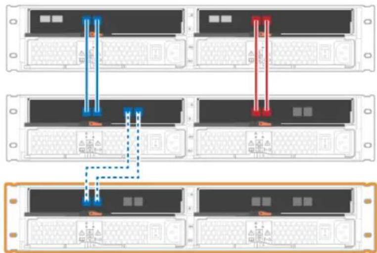
flowchart
graph TD
    A["Server Rack 1"] --> B["Data Bus"]
    B --> C["Server Rack 2"]
    C --> D["Data Bus"]
    D --> E["Server Rack 3"]
    E --> F["Data Bus"]
    F --> G["Server Rack 4"]
    style A fill:#f9f,stroke:#333
    style C fill:#f9f,stroke:#333
    style E fill:#f9f,stroke:#333
    style F fill:#f9f,stroke:#333
Figure 12. Single-stack diagram (2U models)

flowchart
graph TD
    subgraph Top
        A["Controller A"] --> B["Controller B"]
        B --> C["SAS-3 IOM"]
        C --> D["SAS-3 IOM"]
    end
    subgraph Bottom
        E["Controller A"] --> F["Controller B"]
        F --> G["SAS-3 IOM"]
        G --> H["SAS-3 IOM"]
    end
    style Top fill:#f9f,stroke:#333
    style Bottom fill:#ccf,stroke:#333
Figure 13. Single-stack diagram (4U models)
Step 2. In ThinkSystem System Manager, click Hardware.
Note: At this point in the procedure, you have only one active path to the controller shelf.
Step 3. Scroll down, as necessary, to see all the drive shelves in the new storage system. If the new drive shelf is not displayed, resolve the connection issue.
Step 4. Select the ESMs/IOMs icon for the new drive shelf.

The Shelf Component Settings dialog box appears.
Step 5. Select the ESMs/IOMs tab in the Shelf Component Settings dialog box.
Step 6. Select Show more options, and verify the following:
- IOM/ESM A is listed.
- Current data rate is 12 Gbps for a SAS-3 drive shelf.
• Card communications is OK.
Step 7. Connect the drive shelf to controller B.
The following figures show an example connection between an additional drive shelf and controller B.
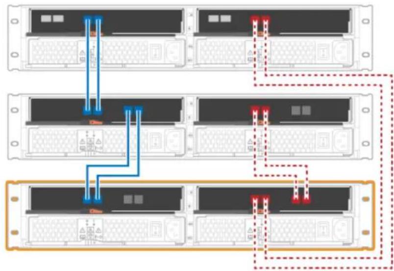
flowchart
graph TD
    A["Server Rack 1"] --> B["Data Flow"]
    B --> C["Server Rack 2"]
    C --> D["Data Flow"]
    D --> E["Server Rack 3"]
    E --> F["Data Flow"]
    F --> G["Server Rack 4"]
    style A fill:#f9f,stroke:#333
    style C fill:#f9f,stroke:#333
    style E fill:#f9f,stroke:#333
    style F fill:#f9f,stroke:#333
Figure 14. 2U controller B single-stack diagram

flowchart
graph TD
    subgraph_Top_1["Controller A"]
        A["Controller A"] --> B["Controller B"]
    end
    subgraph_Bottom_2["SAS-3 IOM"]
        B --> C["SAS-3 IOM"]
    end
    A --> D["Controler A"]
    B --> E["Controler B"]
    C --> F["SAS-3 IOM"]
    D --> G["Controler A"]
    E --> H["Controler B"]
Figure 15. 4U controller B single-stack diagram
Step 8. If it is not already selected, select the ESMs/IOMs tab in the Shelf Component Settings dialog box, and then select Show more options. Verify that Card communications is YES.
Note: Optimal status indicates that the loss of redundancy error associated with the new drive shelf has been resolved and the storage system is stabilized.
Go to "Complete hot add" on page 45.
Complete hot add
You complete the hot add by checking for any errors and confirming that the newly added drive shelf uses the latest firmware.
Step 1. In ThinkSystem System Manager, click Home.
Step 2. If the link labeled Recover from problems appears at the center top of the page, click the link, and resolve any issues indicated in the Recovery Guru.
Step 3. In ThinkSystem System Manager, click Hardware, and scroll down, as necessary, to see the newly added drive shelf.
Step 4. For drives that were previously installed in a different storage system, add one drive at time to the newly installed drive shelf. Wait for each drive to be recognized before you insert the next drive. When a drive is recognized by the storage system, the representation of the drive slot in the Hardware page displays as a blue rectangle.
Step 5. Select Support → Support Center → Support Resources tab.
Step 6. Click the Software and Firmware Inventory link, and check which versions of the IOM/ESM firmware and the drive firmware are installed on the new drive shelf.
Note: You might need to scroll down the page to locate this link.
Step 7. If necessary, upgrade the drive firmware. IOM/ESM firmware automatically upgrades to the latest version unless you have disabled the upgrade feature.
The hot add procedure is complete. You can resume normal operations.
Ethernet cabling for a management station
You can connect your storage system to an Ethernet network for out-of-band storage array management. You must use Ethernet cables for all storage array management connections.
Direct topology
A direct topology connects your controller directly to an Ethernet network.
You must connect management port 1 on each controller for out-of-band management and leave port 2 available for access to the storage array by technical support.
Direct storage management connections

flowchart
graph TD
    A["Controller A"] --> B["Storage Management Station"]
    C["Controller B"] --> B
    B --> D["Network Interface Card"]
    B --> E["Network Interface Card"]
    D --> F["Ethernet Port"]
    D --> G["Ethernet Port"]
    E --> H["Ethernet Port"]
    E --> I["Ethernet Port"]
Switch topology
A switch topology uses a switch to connect your controller to an Ethernet network.
Note: You must connect management port 1 on each controller for out-of-band management and leave port 2 available for access to the storage array by technical support.
Switch storage management connections
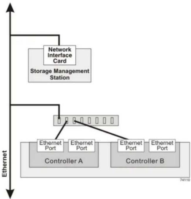
flowchart
graph TD
    A["Controller A"] -->|Ethernet Port| B["Storage Management Station"]
    B --> C["Network Interface Card"]
    C --> D["Controller B"]
    D -->|Ethernet Port| E["Storage Management Station"]
    E --> F["Ethernet Port"]
    F --> G["Controller A"]
    style A fill:#f9f,stroke:#333
    style B fill:#ccf,stroke:#333
    style C fill:#cfc,stroke:#333
    style D fill:#fcc,stroke:#333
    style E fill:#ffc,stroke:#333
    style F fill:#cff,stroke:#333
    style G fill:#ffc,stroke:#333
Windows express configuration
This chapter describes how to configure a Windows-based host using the express configuration method.
Decide whether to use this Express method
The express method for installing your storage array and accessing ThinkSystem System Manager is appropriate for setting up a standalone Windows host to a DE Series system. It is designed to get the storage system up and running as quickly as possible with minimal decision points.
The express method includes the following steps:
-
Setting up one of the following communication environments:
-
Fibre Channel (FC)
-
iSCSI
• SAS -
Creating logical volumes on the storage array and assigning a logical unit number (LUN) to each volume.
- Making the volume LUNs available to the data host.
This guide is based on the following assumptions:
| Component Assumptions | |
| Hardware | You have used the Installation and Setup Instructions included with the controller shelves to install the hardware.You have connected cables between the optional drive shelves and the array controllers.You have applied power to the storage array.You have installed all other hardware (for example, management station, switches) and made the necessary connections. |
| Host | You have made a connection between the storage array and the data host.You have installed the host operating system.You are not using Windows as a virtualized guest.You are not configuring the data (I/O attached) host to boot from SAN. |
| Storage management station | You are using a 1 Gbps or faster management network.You are using a separate station for management rather than the data (I/O attached) host.You are using out-of-band management, in which a storage management station sends commands to the storage array through the Ethernet connections to the controller.You have attached the management station to the same subnet as the storage management ports. |
| IP addressing | You have not yet made an Ethernet connection between the management station and the storage array. |
| Storage provisioning | You will not use shared volumes.You will create pools rather than volume groups. |
| Protocol: FC | You have made all host-side FC connections and activated switch zoning.You are using Lenovo-supported FC HBAs and switches.You are using FC HBA driver versions as listed on the DE Series Product Support Site. |
| Protocol: iSCSI | You are using Ethernet switches capable of transporting iSCSI traffic.You have configured the Ethernet switches according to the vendor's recommendation for iSCSI. |
| Protocol: SAS | You are using Lenovo-supported SAS HBAs.You are using SAS HBA driver versions as listed on theDE Series Product Support Site. |
Understand the workflow
This workflow guides you through the express method for configuring your storage array and ThinkSystem System Manager to make storage available to a host.
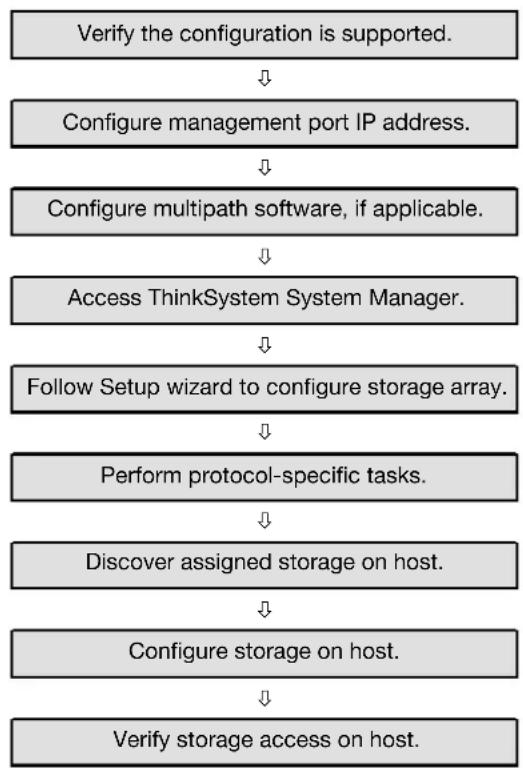
flowchart
graph TD
    A["Verify the configuration is supported."] --> B["Configure management port IP address."]
    B --> C["Configure multipath software, if applicable."]
    C --> D["Access ThinkSystem System Manager."]
    D --> E["Follow Setup wizard to configure storage array."]
    E --> F["Perform protocol-specific tasks."]
    F --> G["Discover assigned storage on host."]
    G --> H["Configure storage on host."]
    H --> I["Verify storage access on host."]
Verify the Windows configuration is supported
To ensure reliable operation, you create an implementation plan and then verify that the entire configuration is supported.
Step 1. Go to the DE Series Product Support Site.
Step 2. Click on the Documentation tab.
Step 3. Look for the Interoperability Matrix document, and click to download or view the file. In this file, you may search for the product family that applies, as well as other criteria for the configuration such as Operating System, ThinkSystem SAN OS, and Host Multipath driver.
Step 4. As necessary, make the updates for your operating system and protocol as listed in the table.
| Operating system updates | Protocol | Protocol-related updates |
| You might need to install out-of-box drivers to ensure proper functionality and supportability.Each HBA vendor has specific methods for updating boot code and firmware. Refer to the support section of the vendor’s website to obtain the instructions and software necessary to update the HBA boot code and firmware. | FC Host bus adapter (HBA) | driver, firmware, and bootcode |
| iSCSI Network interface card | NIC) driver, firmware and bootcode | |
| SAS Host bus adapter (HBA) | driver, firmware, and bootcode |
Configure management port IP addresses
Configure the management port for communication between the management station and array controllers.
Before you begin
- You have obtained the network configuration information from your network administrator for the controllers (IP address, subnet mask, and gateway or IP address and routable IP address).
- You have turned on the legacy management interface (SYMbol). If you have disabled the interface, see the ThinkSystem System Manager online help or the Command Line Reference for information on re-enabling it.
For detailed information on how to configure your management port, refer to the Installation and Setup Instructions that comes with your system.
Configure the multipath software
Multipath software provides a redundant path to the storage array in case one of the physical paths is disrupted. Before you can use multipathing, you need to install ThinkSystem Storage Manager. This software contains the multipath package for Windows.
Windows installations use the native MPIO Device Specific Module (DSM) driver for failover. When you install ThinkSystem Storage Manager, the DSM driver is installed and enabled. You do not need to take further action to use multipath.
Installing ThinkSystem Storage Manager
Perform the following steps to install ThinkSystem Storage Manager and use the multipath package for Windows.
Before you begin
- You must have the correct administrator or superuser privileges.
- You must have ensured that the system that will contain the ThinkSystem Storage Manager client has the following minimum requirements:
- RAM: 2 GB for Java Runtime Engine
- OS/Architecture: Refer to DE Series Product Support Site Drivers&Software → Product Firmware for guidance on determining the supported operating system versions and architectures.
- Disk space: 5 GB
You will install the ThinkSystem Storage Manager software on the management station.
Step 1. Download the ThinkSystem Storage Manager software release from DE Series Product Support Site Drivers&Software → Product Firmware
Step 2. Run the ThinkSystem Storage Manager installer. Do one of the following depending on the operating system:
| Windows Linux | |
| Double-click the SMIA*.exe installation package to start the installation. | 1. Go to the directory where the SMIA*.bin installation package is located.2. If the temp mount point does not have execute permissions, set the IATEMPDIR variable. Example:IIAATTEEMMPPDDIIRR==//rroooott ../SSMMIIAA--LLIINNUUX 11.25.0A00.0002.bin3. Run the chmod +x SMIA*.bin command to grant execute permission to the file.4. Run the ./SMIA*.bin command to start the installer. |
Step 3. Use the installation wizard to install the software on the management station.
Install ThinkSystem Storage Manager for SMcli and Host Context Agent (HCA)
When you install the ThinkSystem Storage Manager software on your management station, the command line interface (CLI) is installed to help you manage your array. By also installing the software on the host, the Host Context Agent is installed that helps the host push configuration information to the storage array controllers through the I/O path.
Before you begin
- You must have the correct administrator or superuser privileges.
-
You must have ensured that the system that will contain the ThinkSystem Storage Manager client has the following minimum requirements:
-
RAM: 2 GB for Java Runtime Engine
- Disk space: 5 GB
- OS/Architecture: Refer to DE Series Product Support Site Drivers&Software → Product Firmware for guidance on determining the supported operating system versions and architectures.
Step 1. Download the ThinkSystem Storage Manager software release from DE Series Product Support Site Drivers&Software → Product Firmware
Step 2. Run the ThinkSystem Storage Manager installer. Do one of the following depending on the operating system:
| Windows Linux | |
| Double-click the SMIA*.exe installation package to start the installation. | 1. Go to the directory where the SMIA*.bin installation package is located.2. If the temp mount point does not have execute permissions, set the IATEMPDIR variable. Example: IIAATTEEMMPPDDIIRR==//rroooott ../SSMMIIAA--LLIINNUUX 11.25.0A00.0002.bin3. Run the chmod +x SMIA*.bin command to grant execute permission to the file.4. Run the ./SMIA*.bin command to start the installer. |
Step 3. Use the installation wizard to install the software on the management station.
Access ThinkSystem System Manager and use the Setup wizard
You use the Setup wizard in ThinkSystem System Manager to configure your storage array.
Before you begin
- You have ensured that the device from which you will access ThinkSystem System Manager contains one of the following browsers:
| Browser Minimum version | |
| Google Chrome | 47 |
| Microsoft Internet Explorer 11 | |
| Microsoft Edge EdgeHTML 12 | |
| Mozilla Firefox | 31 |
| Safari | 9 |
- You are using out-of-band management.
If you are an iSCSI user, make sure you have closed the Setup wizard while configuring iSCSI.
The wizard automatically relaunches when you open System Manager or refresh your browser and at least one of the following conditions is met:
- No pools and volume groups are detected.
- No workloads are detected.
- No notifications are configured.
If the Setup wizard does not automatically appear, contact technical support.
Step 1. From your browser, enter the following URL: https://
IIPPAAddddrreessss is the address for one of the storage array controllers.
The first time ThinkSystem System Manager is opened on an array that has not been configured, the Set Administrator Password prompt appears. Role-based access management configures four local roles: admin, support, security, and monitor. The latter three roles have random passwords that cannot be guessed. After you set a password for the admin role you can change all of the passwords using the admin credentials. See ThinkSystem System Manager online help for more information on the four local user roles.
Step 2. Enter the System Manager password for the admin role in the Set Administrator Password and Confirm Password fields, and then select the Set Password button. When you open System Manager and no pools, volumes groups, workloads, or notifications have been configured, the Setup wizard launches.
Step 3. Use the Setup wizard to perform the following tasks:
- Verify hardware (controllers and drives) – Verify the number of controllers and drives in the storage array. Assign a name to the array.
- Verify hosts and operating systems – Verify the host and operating system types that the storage array can access.
- Accept pools – Accept the recommended pool configuration for the express installation method. A pool is a logical group of drives.
- Configure alerts – Allow System Manager to receive automatic notifications when a problem occurs with the storage array.
- Enable AutoSupport – Automatically monitor the health of your storage array and have dispatches sent to technical support.
Step 4. If you have not already created a volume, create one by going to Storage → Volumes → Create → Volume. For more information, see the online help for ThinkSystem System Manager.
Perform FC-specific tasks
For the Fibre Channel protocol, you configure the switches and determine the host port identifiers.
Configuring the FC switches - Windows
Configuring (zoning) the Fibre Channel (FC) switches enables the hosts to connect to the storage array and limits the number of paths. You zone the switches using the management interface for the switches.
Before you begin
- You must have administrator credentials for the switches.
- You must have used your HBA utility to discover the WWPN of each host initiator port and of each controller target port connected to the switch.
For details about zoning your switches, see the switch vendor's documentation.
You must zone by WWPN, not by physical port. Each initiator port must be in a separate zone with all of its corresponding target ports.
Step 1. Log in to the FC switch administration program, and then select the zoning configuration option.
Step 2. Create a new zone that includes the first host initiator port and that also includes all of the target ports that connect to the same FC switch as the initiator.
Step 3. Create additional zones for each FC host initiator port in the switch.
Step 4. Save the zones, and then activate the new zoning configuration.
Determining host WWPNs and making the recommended settings - FC, Windows
You install an FC HBA utility so you can view the worldwide port name (WWPN) of each host port. Additionally, you can use the HBA utility to change any settings recommended in the Interoperability Matrix document for the supported configuration.
Guidelines for HBA utilities:
- Most HBA vendors offer an HBA utility. You will need the correct version of HBA for your host operating system and CPU. Examples of FC HBA utilities include:
- Emulex OneCommand Manager for Emulex HBAs
– QLogic QConverge Console for QLogic HBAs
- Host I/O ports might automatically register if the host context agent is installed.
Step 1. Download the appropriate utility from your HBA vendor's web site.
Step 2. Install the utility.
Step 3. Select the appropriate settings in the HBA utility.
Appropriate settings for your configuration are listed in the Interoperability Matrix document. Go to DE Series Product Support Site, click on the Documentation tab, and look for the Interoperability Matrix document.
FC worksheet for Windows
You can use this worksheet to record FC storage configuration information. You need this information to perform provisioning tasks.
The illustration shows a host connected to a DE Series storage array in two zones. One zone is indicated by the blue line; the other zone is indicated by the red line. Any single port has two paths to the storage (one to each controller).

flowchart
graph TD
    A["1"] --> B["2"]
    B --> C["3"]
    C --> D["4"]
    D --> E["5"]
    E --> F["6"]
    B --> G["7"]
    C --> H["8"]
    D --> I["9"]
    F --> J["1"]
    G --> K["2"]
    H --> L["3"]
    I --> M["4"]
    J --> N["5"]
    K --> O["6"]
    L --> P["7"]
    M --> Q["8"]
    N --> R["9"]
Host identifiers
| Callout No. | Host (initiator) port connections | WWPN |
| 1 Host not applicable | ||
| 2 | Host port 0 to FC switch zone 0 | |
| 7 | Host port 1 to FC switch zone 1 | |
Target identifiers
| Callout No. | Array controller (target) port connections | WWPN |
| 3 | Switch not applicable | |
| 6 | Array controller (target) not applicable | |
| 5 | Controller A, port 1 to FC switch 1 | |
| 9 | Controller A, port 2 to FC switch 2 | |
| 4 | Controller B, port 1 to FC switch 1 | |
| 8 | Controller B, port 2 to FC switch 2 |
Mapping host
| Mapping host name | |
| Host OS type |
Perform iSCSI-specific tasks
For the iSCSI protocol, you configure the switches and configure networking on the array side and the host side. Then you verify the IP network connections.
Configuring the switches - iSCSI, Windows
You configure the switches according to the vendor's recommendations for iSCSI. These recommendations might include both configuration directives as well as code updates.
You must ensure the following:
- You have two separate networks for high availability. Make sure that you isolate your iSCSI traffic to separate network segments.
- You have enabled send and receive hardware flow control end to end.
- You have disabled priority flow control.
- If appropriate, you have enabled jumbo frames.
Notes:
- Port channels/LACP is not supported on the controller's switch ports. Host-side LACP is not recommended; multipathing provides the same, and in some cases better, benefits.
- Forward Error Correction (FEC) must be turned off for 25G iSCSI network.
Configuring networking - iSCSI Windows
You can set up your iSCSI network in many ways, depending on your data storage requirements.
Consult your network administrator for tips on selecting the best configuration for your environment.
An effective strategy for configuring the iSCSI network with basic redundancy is to connect each host port and one port from each controller to separate switches and partition each set of host and controller ports on separate network segments using VLANs.
You must enable send and receive hardware flow control end to end. You must disable priority flow control.
If you are using jumbo frames within the IP SAN for performance reasons, make sure to configure the array, switches, and hosts to use jumbo frames. Consult your operating system and switch documentation for information on how to enable jumbo frames on the hosts and on the switches. To enable jumbo frames on the array, complete the steps in Configuring array-side networking—iSCSI.
Note: Many network switches have to be configured above 9,000 bytes for IP overhead. Consult your switch documentation for more information.
Configuring array-side networking - iSCSI, Windows
You use the ThinkSystem System Manager GUI to configure iSCSI networking on the array side.
Before you begin
- You must know the IP address or domain name for one of the storage array controllers.
- You or your system administrator must have set up a password for the System Manager GUI, or you must configured Role-Based Access Control (RBAC) or LDAP and a directory service for the appropriate security access to the storage array. See the ThinkSystem System Manager online help for more information about Access Management.
This task describes how to access the iSCSI port configuration from the Hardware page. You can also access the configuration from System > Settings > Configure iSCSI ports.
Step 1. From your browser, enter the following URL: https://
IIPPAAddddrreesss is the address for one of the storage array controllers.
The first time ThinkSystem System Manager is opened on an array that has not been configured, the Set Administrator Password prompt appears. Role-based access management configures four local roles: admin, support, security, and monitor. The latter three roles have random passwords that cannot be guessed. After you set a password for the admin role you can change all of the passwords using the admin credentials. See ThinkSystem System Manager online help for more information on the four local user roles.
Step 2. Enter the System Manager password for the admin role in the Set Administrator Password and Confirm Password fields, and then select the Set Password button. When you open System Manager and no pools, volumes groups, workloads, or notifications have been configured, the Setup wizard launches.
Step 3. Close the Setup wizard. You will use the wizard later to complete additional setup tasks.
Step 4. Select Hardware.
Step 5. If the graphic shows the drives, click Show back of shelf. The graphic changes to show the controllers instead of the drives.
Step 6. Click the controller with the iSCSI ports you want to configure. The controller's context menu appears.
Step 7. Select Configure iSCSI ports. The Configure iSCSI Ports dialog box opens.
Step 8. In the drop-down list, select the port you want to configure, and then click Next.
Step 9. Select the configuration port settings, and then click Next. To see all port settings, click the Show more port settings link on the right of the dialog box.
| Port Setting | Description |
| Configured Ethernet port speed | Select the desired speed.The options that appear in the drop-down list depend on the maximum speed that your network can support (for example, 10 Gbps).Note:The optional iSCSI host interface cards in the DE6000H and DE6000F controllers do not auto-negotiate speeds. You must set the speed for each port to either 10 Gb or 25 Gb. All ports must be set to the same speed. |
| Enable IPv4 / Enable IPv6 | Select one or both options to enable support for IPv4 and IPv6 networks. |
| TCP listening port(Available by clicking Show more port settings.) | If necessary, enter a new port number.The listening port is the TCP port number that the controller uses to listen for iSCSI logins from host iSCSI initiators. The default listening port is 3260. You must enter 3260 or a value between 49152 and 65535. |
| MTU size(Available by clicking Show more port settings.) | If necessary, enter a new size in bytes for the Maximum Transmission Unit (MTU).The default Maximum Transmission Unit (MTU) size is 1500 bytes per frame. You must enter a value between 1500 and 9000. |
| Enable ICMP PING responses Select this option to enable the Internet Control Message Protocol (ICMP). The operating systems of networked computers use this protocol to send messages. These ICMP messages determine whether a host is reachable and how long it takes to get packets to and from that host. | |
If you selected Enable IPv4, a dialog box opens for selecting IPv4 settings after you click Next. If you selected Enable IPv6, a dialog box opens for selecting IPv6 settings after you click Next. If you selected both options, the dialog box for IPv4 settings opens first, and then after you click Next, the dialog box for IPv6 settings opens.
Step 10. Configure the IPv4 and/or IPv6 settings, either automatically or manually. To see all port settings, click the Show more settings link on the right of the dialog box.
| Port setting | Description |
| Automatically obtain configuration | Select this option to obtain the configuration automatically. |
| Manually specify static configuration | Select this option, and then enter a static address in the fields. For IPv4, include the network subnet mask and gateway. For IPv6, include the routable IP address and router IP address. |
| Enable VLAN support (Available by clicking Show more settings.) | Important: This option is only available in an iSCSI environment. Select this option to enable a VLAN and enter its ID. A VLAN is a logical network that behaves like it is physically separate from other physical and virtual local area networks (LANs) supported by the same switches, the same routers, or both. |
| Enable ethernet priority (Available by clicking Show more settings.) | Important: This option is only available in an iSCSI environment. Select this option to enable the parameter that determines the priority of accessing the network. Use the slider to select a priority between 1 and 7.In a shared local area network (LAN) environment, such as Ethernet, many stations might contend for access to the network. Access is on a first-come, first-served basis. Two stations might try to access the network at the same time, which causes both stations to back off and wait before trying again. This process is minimized for switched Ethernet, where only one station is connected to a switch port. |
Step 11. Click Finish.
Step 12. Close System Manager.
Configuring host-side networking—iSCSI
You must configure iSCSI networking on the host side so that the Microsoft iSCSI Initiator can establish sessions with the array.
Before you begin
- You have fully configured the switches that will be used to carry iSCSI storage traffic.
-
You must have enabled send and receive hardware flow control end to end and disabled priority flow control.
-
You have completed the array side iSCSI configuration.
- You must know the IP address of each port on the controller.
These instructions assume that two NIC ports will be used for iSCSI traffic.
Step 1. Disable unused network adapter protocols.
These protocols include, but are not limited to, QoS, File and Print Sharing, and NetBIOS.
Step 2. Execute > iscsicl.exe from a terminal window on the host to open the iSCSI Initiator Properties dialog box.
Step 3. On the Discovery tab, select Discover Portal, and then enter the IP address of one of the iSCSI target ports.
Step 4. On the Targets tab, select the first target portal you discovered and then select Connect.
Step 5. Select Enable multi-path, select Add this connection to the list of Favorite Targets, and then select Advanced.
Step 6. For Local adapter, select Microsoft iSCSI Initiator.
Step 7. For Initiator IP, select the IP address of a port on the same subnet or VLAN as one of the iSCSI targets.
Step 8. For Target IP, select the IP address of a port on the same subnet as the Initiator IP selected in the step above.
Step 9. Retain the default values for the remaining check boxes, and then select OK.
Step 10. Select OK again as you return to the Connect to Target dialog box.
Step 11. Repeat this procedure for each initiator port and session (logical path) to the storage array that you want to establish.
Verifying IP network connections - iSCSI, Windows
You verify Internet Protocol (IP) network connections by using ping tests to ensure the host and array are able to communicate.
Step 1. Select Start → All Programs → Accessories → Command Prompt, and use the Windows CLI to run one of the following commands, depending on whether jumbo frames are enabled:
If jumbo frames are not enabled, run this command:
ping -s
If jumbo frames are enabled, run the ping command with a payload size of 8,972 bytes. The IP and ICMP combined headers are 28 bytes, which when added to the payload, equals 9,000 bytes. The -f switch sets the don't fragment (DF) bit. The -l switch allows you to set the size. These options allow jumbo frames of 9,000 bytes to be successfully transmitted between the iSCSI initiator and the target.
ping -l 8972 -f
In this example, the iSCSI target IP address is 192.0.2.8.
C:>ping -l 8972 -f 192.0.2.8
Pinging 192.0.2.8 with 8972 bytes of data:
Reply from 192.0.2.8: bytes=8972 time=2ms TTL=64
Reply from 192.0.2.8: bytes=8972 time=2ms TTL=64
Reply from 192.0.2.8: bytes=8972 time=2ms TTL=64
Reply from 192.0.2.8: bytes=8972 time=2ms TTL=64
Ping statistics for 192.0.2.8:
Packets: Sent = 4, Received = 4, Lost = 0 (0% loss),
Approximate round trip times in milli-seconds:
Minimum = 2ms, Maximum = 2ms, Average = 2ms
Step 2. Issue a ping command from each host's initiator address (the IP address of the host Ethernet port used for iSCSI) to each controller iSCSI port. Perform this action from each host server in the configuration, changing the IP addresses as necessary.
Note: If the command fails (for example, returns Packet needs to be fragmented but DF set), verify the MTU size (jumbo frame support) for the Ethernet interfaces on the host server, storage controller, and switch ports.
Recording iSCSI-specific information for Windows
Select the iSCSI worksheet to record your protocol-specific storage configuration information. You need this information to perform provisioning tasks.
iSCSI worksheet - Windows
You can use this worksheet to record iSCSI storage configuration information. You need this information to perform provisioning tasks.
Recommended configuration
Recommended configurations consist of two initiator ports and four target ports with one or more VLANs.

flowchart
graph TD
    subgraph_Server_1["Server 1"]
        A1[" "] --> B1[" "]
        A2[" "] --> B2[" "]
        A3[" "] --> B3[" "]
    end
    subgraph_Server_2["Server 2"]
        C1[" "] --> D1[" "]
        C2[" "] --> D2[" "]
        C3[" "] --> D3[" "]
    end
    B1 --> E["Cloud Network"]
    B2 --> E
    B3 --> E
    style E fill:#f9f,stroke:#333,stroke-width:2px
    note right of E "iSCSI Network"
Target IQN
| Callout No. | Target port connection | IQN |
| 2 Target port | ||
Mappings host name
| CalloutNo. Host information | Name and type |
| 1 Mappings host name | |
| Host OS type |
Perform SAS-specific tasks
For the SAS protocol, you determine host port addresses and make the settings recommended in the Interoperability Matrix document.
Determining SAS host identifiers - Windows
For the SAS protocol, you find the SAS addresses using the HBA utility, then use the HBA BIOS to make the appropriate configuration settings.
Guidelines for HBA utilities:
- Most HBA vendors offer an HBA utility. Depending on your host operating system and CPU, use either the LSI-sas2flash(6G) or sas3flash(12G) utility.
- Host I/O ports might automatically register if the host context agent is installed.
Step 1. Download the LSI-sas2flash(6G) or sas3flash(12G) utility from your HBA vendor's web site.
Step 2. Install the utility.
Step 3. Use the HBA BIOS to select the appropriate settings for your configuration.
Go to DE Series Product Support Site, click on the Documentation tab, and look for the Interoperability Matrix document for recommendations.
Recording SAS-specific information for Windows
Record your protocol-specific storage configuration information on the SAS worksheet. You need this information to perform provisioning tasks.
SAS worksheet - Windows
You can use this worksheet to record SAS storage configuration information. You need this information to perform provisioning tasks.
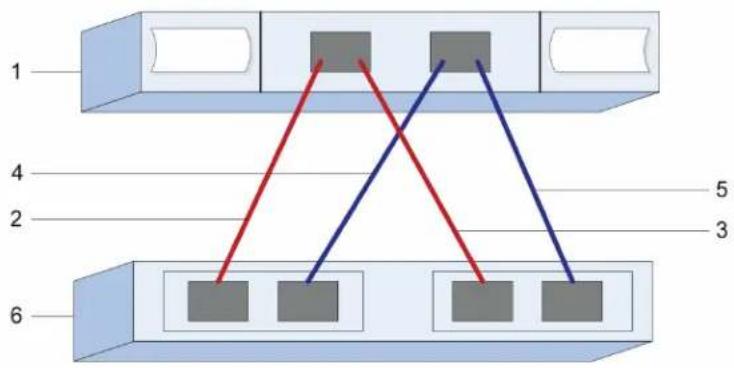
flowchart
graph TD
    A["Component 1"] --> B["Node 1"]
    A --> C["Node 2"]
    A --> D["Node 3"]
    A --> E["Node 4"]
    A --> F["Node 5"]
    A --> G["Node 6"]
Host Identifiers
| Callout No. | Host (initiator) port connections | SAS address |
| 1 Host not applicable | ||
| 2 | Host (initiator) port 1 connected to Controller A, port 1 | |
| 3 | Host (initiator) port 1 connected to Controller B, port 1 | |
| 4 | Host (initiator) port 2 connected to Controller A, port 1 | |
| 5 | Host (initiator) port 2 connected to Controller B, port 1 | |
Target Identifiers
Recommended configurations consist of two target ports.
Mappings Host
| Mappings Host Name | |
| Host OS Type |
Discover storage on the host
LUNs on your storage system appear as disks to the Windows host. When you add new LUNs, you must manually rescan the associated disks to discover them. The host does not automatically discover new LUNs.
Before you begin
You must be logged on as an administrator.
Step 1. To discover the storage, run the following command from a Windows command prompt. # echo rreesccaann || ddiisskkppaarrtt
Step 2. To verify the addition of new storage, run the following command. # echo list disk | diskpart
Configure storage on the host
A new LUN is offline and has no partition or file system when a Windows host first discovers it. You must bring the volume online and initialize it in Windows. Optionally, you can format the LUN with a file system.
The host must have discovered the LUN.
You can initialize the disk as a basic disk with a GPT or MBR partition table. Typically, you format the LUN with a file system such as New Technology File System (NTFS).
Step 1. From a Windows command prompt, enter the diskpart context.
diskpart
Step 2. View the list of available disks.
list disk
Step 3. Select the disk to bring online.
select disk 1
Step 4. Bring the disk online.
online disk
Step 5. Create a partition.
create partition primary
Note: In Windows Server 2008 and later, you are prompted immediately after creating the partition to format the disk and give it a name. Select Cancel on the prompt to continue using these instructions for formatting and naming the partition.
Step 6. Assign a drive letter.
assign letter=f
Step 7. Format the disk.
format FS=NTFS LABEL="New Volume" QUICK
Step 8. Exit the ddiisskkppaarrtt context.
exit
Verify storage access on the host
Before using the volume, you verify that the host can write data to the LUN and read it back.
Before you begin
You must have initialized the LUN and formatted it with a file system.
Step 1. Create and write to a file on the new LUN.
echo test file > f:\test.txt
Step 2. Read the file and verify data was written.
type f:\test.txt
Step 3. To verify that multipath is working, change the volume ownership.
a. From the ThinkSystem System Manager GUI, go to Storage → Volumes, and then select More → Change ownership.
b. On the Change Volume Ownership dialog box, use the Preferred Owner pull-down to select the other controller for one of the volumes in the list, and then confirm the operation.
c. Verify that you can still access the files on the LUN.
dir f:\
Step 4. Find the target ID.
Note: The dsmUtil utility is case sensitive.
C:\Program Files (x86)\DSMDrivers\mppdsm\dsmUtil.exe -a
Step 5. View the paths to the LUN and verify that you have the expected number of paths. In the
C:\Program Files (x86)\DSMDrivers\mppdsm\dsmUtil.exe -g
VMware express configuration
This chapter describes how to configure a VMware-based host using the express configuration method.
Deciding whether to use this Express method
The express method for installing your storage array and accessing ThinkSystem System Manager is appropriate for setting up a standalone VMware host to a DE Series storage system. It is designed to get the storage system up and running as quickly as possible with minimal decision points.
The express method includes the following steps:
-
Setting up one of the following communication environments:
-
Fibre Channel (FC)
- iSCSI
-
SAS
-
Creating logical volumes on the storage array and assigning a logical unit number (LUN) to each volume.
- Making the volume LUNs available to the data host.
This guide is based on the following assumptions:
| Component Assumptions | |
| Hardware | You have used the Installation and Setup Instructions included with the controller shelves to install the hardware.You have connected cables between the optional drive shelves and the array controllers.You have applied power to the storage array.You have installed all other hardware (for example, management station, switches) and made the necessary connections. |
| Host | You have made a connection between the storage array and the data host.You have installed the host operating system.You are not using Windows as a virtualized guest.You are not configuring the data (I/O attached) host to boot from SAN. |
| Storage management station | You are using a 1 Gbps or faster management network.You are using a separate station for management rather than the data (I/O attached) host.You are using out-of-band management, in which a storage management station sends commands to the storage array through the Ethernet connections to the controller.You have attached the management station to the same subnet as the storage management ports. |
| IP addressing | You have not yet made an Ethernet connection between the management station and the storage array. |
| Storage provisioning | You will not use shared volumes.You will create pools rather than volume groups. |
| Protocol: FC | You have made all host-side FC connections and activated switch zoning.You are using Lenovo-supported FC HBAs and switches.You are using FC HBA driver versions as listed on the DE Series Product Support Site. |
| Protocol: iSCSI | You are using Ethernet switches capable of transporting iSCSI traffic.You have configured the Ethernet switches according to the vendor's recommendation for iSCSI. |
| Protocol: SAS | You are using Lenovo-supported SAS HBAs.You are using SAS HBA driver versions as listed on the DE Series Product Support Site. |
Understand the workflow
This workflow guides you through the express method for configuring your storage array and ThinkSystem System Manager to make storage available to a host.

flowchart
graph TD
    A["Verify the configuration is supported."] --> B["Configure management port IP address."]
    B --> C["Configure multipath software, if applicable."]
    C --> D["Access ThinkSystem System Manager."]
    D --> E["Follow Setup wizard to configure storage array."]
    E --> F["Perform protocol-specific tasks."]
    F --> G["Discover assigned storage on host."]
    G --> H["Configure storage on host."]
    H --> I["Verify storage access on host."]
Verify the VMware configuration is supported
To ensure reliable operation, you create an implementation plan and then verify that the entire configuration is supported.
Step 1. Go to the DE Series Product Support Site.
Step 2. Click on the Documentation tab.
Step 3. Look for the Interoperability Matrix document, and click to download or view the file. In this file, you may search for the product family that applies, as well as other criteria for the configuration such as Operating System, ThinkSystem SAN OS, and Host Multipath driver.
Step 4. As necessary, make the updates for your operating system and protocol as listed in the table.
| Operating system updates | Protocol | Protocol-related updates |
| You might need to install out-of-box drivers to ensure proper functionality and supportability.Each HBA vendor has specific methods for updating boot code and firmware. Refer to the support section of the vendor's website to obtain the instructions and software necessary to update the HBA boot code and firmware. | FC Host bus adapter (HBA) | driver, firmware, and bootcode |
| iSCSI Network interface card (NIC) | driver, firmware and bootcode | |
| SAS Host bus adapter (HBA) | driver, firmware, and bootcode |
Configure management port IP addresses
Configure the management port for communication between the management station and array controllers.
Before you begin
- You have obtained the network configuration information from your network administrator for the controllers (IP address, subnet mask, and gateway or IP address and routable IP address).
- You have turned on the legacy management interface (SYMBOL). If you have disabled the interface, see the ThinkSystem System Manager online help or the Command Line Reference for information on re-enabling it.
For detailed information on how to configure your management port, refer to the Installation and Setup Instructions that comes with your system.
Configure the multipath software
Multipath software provides a redundant path to the storage array in case one of the physical paths is disrupted. The multipath software presents the operating system with a single virtual device that represents the active physical paths to the storage. The multipath software also manages the failover process that updates the virtual device. For VMware, you use the inbox Native Multipathing Plug-in (NMP).
VMware provides plug-ins, known as Storage Array Type Plug-ins (SATP), to handle the failover implementations of specific vendors' storage arrays. The SATP you should use is VMW_SATP_ALUA.
Install ThinkSystem Storage Manager for SMcli and Host Context Agent (HCA)
When you install the ThinkSystem Storage Manager software on your management station, the command line interface (CLI) is installed to help you manage your array. By also installing the software on the host, the Host Context Agent is installed that helps the host push configuration information to the storage array controllers through the I/O path.
Before you begin
- You must have the correct administrator or superuser privileges.
- You must have ensured that the system that will contain the ThinkSystem Storage Manager client has the following minimum requirements:
- RAM: 2 GB for Java Runtime Engine
- Disk space: 5 GB
- OS/Architecture: Refer to DE Series Product Support Site Drivers&Software → Product Firmware for guidance on determining the supported operating system versions and architectures.
This section describes how to install ThinkSystem Storage Manager on the Windows platform only.
Step 1. Download the ThinkSystem Storage Manager software release from DE Series Product Support Site Drivers&Software → Product Firmware.
Step 2. Run the ThinkSystem Storage Manager installer. Double-click the SMIA*.exe installation package to start the installation.
Step 3. Use the installation wizard to install the software on the management station.
Access ThinkSystem System Manager and use the Setup wizard
You use the Setup wizard in ThinkSystem System Manager to configure your storage array.
Before you begin
- You have ensured that the device from which you will access ThinkSystem System Manager contains one of the following browsers:
| Browser Minimum version | |
| Google Chrome | 47 |
| Microsoft Internet Explorer 11 | |
| Microsoft Edge EdgeHTML 12 | |
| Mozilla Firefox | 31 |
| Safari | 9 |
- You are using out-of-band management.
If you are an iSCSI user, make sure you have closed the Setup wizard while configuring iSCSI.
The wizard automatically relaunches when you open System Manager or refresh your browser and at least one of the following conditions is met:
- No pools and volume groups are detected.
- No workloads are detected.
- No notifications are configured.
If the Setup wizard does not automatically appear, contact technical support.
Step 1. From your browser, enter the following URL: https://
IIPPAAddddrreessss is the address for one of the storage array controllers.
The first time ThinkSystem System Manager is opened on an array that has not been configured, the Set Administrator Password prompt appears. Role-based access management configures four local roles: admin, support, security, and monitor. The latter three roles have random passwords that cannot be guessed. After you set a password for the admin role you can change all of the passwords using the admin credentials. See ThinkSystem System Manager online help for more information on the four local user roles.
Step 2. Enter the System Manager password for the admin role in the Set Administrator Password and Confirm Password fields, and then select the Set Password button. When you open System Manager and no pools, volumes groups, workloads, or notifications have been configured, the Setup wizard launches.
Step 3. Use the Setup wizard to perform the following tasks:
- Verify hardware (controllers and drives) – Verify the number of controllers and drives in the storage array. Assign a name to the array.
- Verify hosts and operating systems – Verify the host and operating system types that the storage array can access.
- Accept pools – Accept the recommended pool configuration for the express installation method. A pool is a logical group of drives.
- Configure alerts – Allow System Manager to receive automatic notifications when a problem occurs with the storage array.
- Enable AutoSupport – Automatically monitor the health of your storage array and have dispatches sent to technical support.
Step 4. If you have not already created a volume, create one by going to Storage → Volumes → Create → Volume. For more information, see the online help for ThinkSystem System Manager.
Perform FC-specific tasks
For the Fibre Channel protocol, you configure the switches and determine the host port identifiers.
Configuring the FC switches - VMware
Configuring (zoning) the Fibre Channel (FC) switches enables the hosts to connect to the storage array and limits the number of paths. You zone the switches using the management interface for the switches.
Before you begin
- You must have administrator credentials for the switches.
- You must have used your HBA utility to discover the WWPN of each host initiator port and of each controller target port connected to the switch.
For details about zoning your switches, see the switch vendor's documentation.
You must zone by WWPN, not by physical port. Each initiator port must be in a separate zone with all of its corresponding target ports.
Step 1. Log in to the FC switch administration program, and then select the zoning configuration option.
Step 2. Create a new zone that includes the first host initiator port and that also includes all of the target ports that connect to the same FC switch as the initiator.
Step 3. Create additional zones for each FC host initiator port in the switch.
Step 4. Save the zones, and then activate the new zoning configuration.
Determining the host port WWPNs—FC
To configure FC zoning, you must determine the worldwide port name (WWPN) of each initiator port.
Step 1. Connect to the ESXi host using SSH or the ESXi shell.
Step 2. Run the following command:
esxcfg-scsidevs -a
Step 3. Record the initiator identifiers. The output will be similar to this example:
vmhba3 lpfc link-up fc.20000090fa05e848:10000090fa05e848 (0000:03:00.0)
Emulex Corporation Emulex LPe16000 16Gb PCIe Fibre Channel Adapter
vmhba4 lpfc link-up fc.20000090fa05e849:10000090fa05e849 (0000:03:00.1)
Emulex Corporation Emulex LPe16000 16Gb PCIe Fibre Channel Adapter
FC worksheet for VMware
You can use this worksheet to record FC storage configuration information. You need this information to perform provisioning tasks.
The illustration shows a host connected to a DE Series storage array in two zones. One zone is indicated by the blue line; the other zone is indicated by the red line. Any single port has two paths to the storage (one to each controller).

flowchart
graph TD
    A["1"] --> B["2"]
    B --> C["3"]
    C --> D["4"]
    D --> E["5"]
    E --> F["6"]
    B --> G["7"]
    C --> H["8"]
    D --> I["9"]
    F --> J["1"]
    G --> K["2"]
    H --> L["3"]
    I --> M["4"]
    J --> N["5"]
    K --> O["6"]
    L --> P["7"]
    M --> Q["8"]
    N --> R["9"]
Host identifiers
| Callout No. | Host (initiator) port connections | WWPN |
| 1 Host not applicable | ||
| 2 | Host port 0 to FC switch zone 0 | |
| 7 | Host port 1 to FC switch zone 1 | |
Target identifiers
| Callout No. | Array controller (target) port connections | WWPN |
| 3 | Switch not applicable | |
| 6 | Array controller (target) not applicable | |
| 5 | Controller A, port 1 to FC switch 1 | |
| 9 | Controller A, port 2 to FC switch 2 | |
| 4 | Controller B, port 1 to FC switch 1 | |
| 8 | Controller B, port 2 to FC switch 2 |
Mapping host
| Mapping host name | |
| Host OS type |
Perform iSCSI-specific tasks
For the iSCSI protocol, you configure the switches and configure networking on the array side and the host side. Then you verify the IP network connections.
Configuring the switches - iSCSI, VMware
You configure the switches according to the vendor's recommendations for iSCSI. These recommendations might include both configuration directives as well as code updates.
You must ensure the following:
- You have two separate networks for high availability. Make sure that you isolate your iSCSI traffic to separate network segments.
- You have enabled send and receive hardware flow control end to end.
- You have disabled priority flow control.
- If appropriate, you have enabled jumbo frames.
Notes:
- Port channels/LACP is not supported on the controller's switch ports. Host-side LACP is not recommended; multipathing provides the same, and in some cases better, benefits.
- Forward Error Correction (FEC) must be turned off for 25G iSCSI network.
Configuring networking - iSCSI VMware
You can set up your iSCSI network in many ways, depending on your data storage requirements.
Consult your network administrator for tips on selecting the best configuration for your environment.
While planning your iSCSI networking, remember that the VMware Configuration Maximums guides state that the maximum supported iSCSI storage paths is 8. You must consider this requirement to avoid configuring too many paths.
By default, the VMware iSCSI software initiator creates a single session per iSCSI target when you are not using iSCSI port binding.
Note: VMware iSCSI port binding is a feature that forces all bound VMkernel ports to log into all target ports that are accessible on the configured network segments. It is meant to be used with arrays that present a single network address for the iSCSI target. Lenovo recommends that iSCSI port binding not be used. For additional information, see the VMware Knowledge Base for the article regarding considerations for using software iSCSI port binding in ESX/ESXi. If the ESXi host is attached to another vendor's storage, Lenovo recommends that you use separate iSCSI vmkernel ports to avoid any conflict with port binding.
To ensure a good multipathing configuration, use multiple network segments for the iSCSI network. Place at least one host-side port and at least one port from each array controller on one network segment, and an identical group of host-side and array-side ports on another network segment. Where possible, use multiple Ethernet switches to provide additional redundancy.
You must enable send and receive hardware flow control end to end. You must disable priority flow control.
If you are using jumbo frames within the IP SAN for performance reasons, make sure to configure the array, switches, and hosts to use jumbo frames. Consult your operating system and switch documentation for information on how to enable jumbo frames on the hosts and on the switches. To enable jumbo frames on the array, complete the steps in Configuring array-side networking—iSCSI.
Note: Many network switches have to be configured above 9,000 bytes for IP overhead. Consult your switch documentation for more information.
Configuring array-side networking - iSCSI, VMware
You use the ThinkSystem System Manager GUI to configure iSCSI networking on the array side.
Before you begin
- You must know the IP address or domain name for one of the storage array controllers.
- You or your system administrator must have set up a password for the System Manager GUI, or you must configured Role-Based Access Control (RBAC) or LDAP and a directory service for the appropriate security access to the storage array. See the ThinkSystem System Manager online help for more information about Access Management.
This task describes how to access the iSCSI port configuration from the Hardware page. You can also access the configuration from System > Settings > Configure iSCSI ports.
Step 1. From your browser, enter the following URL: https://
IIPPAAddddrreesss is the address for one of the storage array controllers.
The first time ThinkSystem System Manager is opened on an array that has not been configured, the Set Administrator Password prompt appears. Role-based access management configures four local roles: admin, support, security, and monitor. The latter three roles have random passwords that cannot be guessed. After you set a password for the admin role you can change all of the passwords using the admin credentials. See ThinkSystem System Manager online help for more information on the four local user roles.
Step 2. Enter the System Manager password for the admin role in the Set Administrator Password and Confirm Password fields, and then select the Set Password button. When you open System Manager and no pools, volumes groups, workloads, or notifications have been configured, the Setup wizard launches.
Step 3. Close the Setup wizard.You will use the wizard later to complete additional setup tasks.
Step 4. Select Hardware.
Step 5. If the graphic shows the drives, click Show back of shelf. The graphic changes to show the controllers instead of the drives.
Step 6. Click the controller with the iSCSI ports you want to configure. The controller's context menu appears.
Step 7. Select Configure iSCSI ports. The Configure iSCSI Ports dialog box opens.
Step 8. In the drop-down list, select the port you want to configure, and then click Next.
Step 9. Select the configuration port settings, and then click Next.To see all port settings, click the Show more port settings link on the right of the dialog box.
| Port Setting | Description |
| Configured Ethernet port speed Select the desired speed.The options that appear in the drop-down list depend on the maximum speed that your network can support (for example, 10 Gbps).Note:The optional iSCSI host interface cards in the DE6000H and DE6000F controllers do not auto-negotiate speeds. You must set the speed for each port to either 10 Gb or 25 Gb. All ports must be set to the same speed. | |
| Enable IPv4 / Enable IPv6 Select one or both options to enable support for IPv4 and IPv6 networks. | |
| TCP listening port(Available by clicking Show more port settings.) | If necessary, enter a new port number.The listening port is the TCP port number that the controller uses to listen for iSCSI logins from host iSCSI initiators. The default listening port is 3260. You must enter 3260 or a value between 49152 and 65535. |
| MTU size(Available by clicking Show more port settings.) | If necessary, enter a new size in bytes for the Maximum Transmission Unit (MTU).The default Maximum Transmission Unit (MTU) size is 1500 bytes per frame. You must enter a value between 1500 and 9000. |
| Enable ICMP PING responses Select this option to enable the Internet Control Message Protocol (ICMP). The operating systems of networked computers use this protocol to send messages. These ICMP messages determine whether a host is reachable and how long it takes to get packets to and from that host. | |
If you selected Enable IPv4, a dialog box opens for selecting IPv4 settings after you click Next. If you selected Enable IPv6, a dialog box opens for selecting IPv6 settings after you click Next. If you selected both options, the dialog box for IPv4 settings opens first, and then after you click Next, the dialog box for IPv6 settings opens.
Step 10. Configure the IPv4 and/or IPv6 settings, either automatically or manually. To see all port settings, click the Show more settings link on the right of the dialog box.
| Port setting Description | |
| Automatically obtain configuration | Select this option to obtain the configuration automatically. |
| Manually specify static configuration | Select this option, and then enter a static address in the fields. For IPv4, include the network subnet mask and gateway. For IPv6, include the routable IP address and router IP address. |
| Enable VLAN support (Available by clicking Show more settings.) | Important: This option is only available in an iSCSI environment. Select this option to enable a VLAN and enter its ID. A VLAN is a logical network that behaves like it is physically separate from other physical and virtual local area networks (LANs) supported by the same switches, the same routers, or both. |
| Enable ethernet priority (Available by clicking Show more settings.) | Important: This option is only available in an iSCSI environment. Select this option to enable the parameter that determines the priority of accessing the network. Use the slider to select a priority between 1 and 7.In a shared local area network (LAN) environment, such as Ethernet, many stations might contend for access to the network. Access is on a first-come, first-served basis. Two stations might try to access the network at the same time, which causes both stations to back off and wait before trying again. This process is minimized for switched Ethernet, where only one station is connected to a switch port. |
Step 11. Click Finish.
Step 12. Close System Manager.
Configuring host-side networking—iSCSI
Configuring iSCSI networking on the host side enables the VMware iSCSI initiator to establish a session with the array.
In this express method for configuring iSCSI networking on the host side, you allow the ESXi host to carry iSCSI traffic over four redundant paths to the storage.
After you complete this task, the host is configured with a single vSwitch containing both VMkernel ports and both VMNICs.
For additional information on configuring iSCSI networking for VMware, see the vSphere Documentation Center for your version of vSphere.
Step 1. Configure the switches that will be used to carry iSCSI storage traffic.
Step 2. Enable send and receive hardware flow control end to end.
Step 3. Disable priority flow control.
Step 4. Complete the array side iSCSI configuration.
Step 5. Use two NIC ports for iSCSI traffic.
Step 6. Use either the vSphere client or vSphere web client to perform the host-side configuration. The interfaces vary in functionality and the exact workflow will vary.
Verifying IP network connections - iSCSI, VMware
You verify Internet Protocol (IP) network connections by using ping tests to ensure the host and array are able to communicate.
Step 1. On the host, run one of the following commands, depending on whether jumbo frames are enabled:
If jumbo frames are not enabled, run this command:
vmkping
If jumbo frames are enabled, run the ping command with a payload size of 8,972 bytes. The IP and ICMP combined headers are 28 bytes, which when added to the payload, equals 9,000 bytes. The -s switch sets the packet size bit. The -d switch sets the DF (Don't Fragment) bit on the IPv4
packet. These options allow jumbo frames of 9,000 bytes to be successfully transmitted between the iSCSI initiator and the target.
vmkping -s 8972 -d
In this example, the iSCSI target IP address is 192.0.2.8.
vmkping -s 8972 -d 192.0.2.8
Pinging 192.0.2.8 with 8972 bytes of data:
Reply from 192.0.2.8: bytes=8972 time=2ms TTL=64
Reply from 192.0.2.8: bytes=8972 time=2ms TTL=64
Reply from 192.0.2.8: bytes=8972 time=2ms TTL=64
Reply from 192.0.2.8: bytes=8972 time=2ms TTL=64
Ping statistics for 192.0.2.8:
Packets: Sent = 4, Received = 4, Lost = 0 (0% loss),
Approximate round trip times in milli-seconds:
Minimum = 2ms, Maximum = 2ms, Average = 2ms
Step 2. Issue a vmkping command from each host's initiator address (the IP address of the host Ethernet port used for iSCSI) to each controller iSCSI port. Perform this action from each host server in the configuration, changing the IP addresses as necessary.
Note: If the command fails with the message sendto() failed (Message too long), verify the MTU size (jumbo frame support) for the Ethernet interfaces on the host server, storage controller, and switch ports.
Step 3. Return to the iSCSI Configuration procedure to finish target discovery.
Recording iSCSI-specific information for VMware
Select the iSCSI worksheet to record your protocol-specific storage configuration information. You need this information to perform provisioning tasks.
iSCSI worksheet - VMware
You can use this worksheet to record iSCSI storage configuration information. You need this information to perform provisioning tasks.
Recommended configuration
Recommended configurations consist of two initiator ports and four target ports with one or more VLANs.

flowchart
graph TD
    subgraph_Server_1["Server 1"]
        A1[" "] --> B1[" "]
        A2[" "] --> B2[" "]
        A3[" "] --> B3[" "]
    end
    subgraph_Server_2["Server 2"]
        C1[" "] --> D1[" "]
        C2[" "] --> D2[" "]
        C3[" "] --> D3[" "]
    end
    B1 --> E["Cloud Network"]
    B2 --> E
    B3 --> E
    style E fill:#f9f,stroke:#333,stroke-width:2px
    note right of E "iSCSI Network"
Target IQN
| Callout No. | Target port connection | IQN |
| 2 Target port | ||
Mappings host name
| CalloutNo. Host information | Name and type |
| 1 Mappings host name | |
| Host OS type |
Perform SAS-specific tasks
For the SAS protocol, you determine host port addresses and make the settings recommended in the Interoperability Matrix document.
Determining SAS host identifiers - VMware
For the SAS protocol, you find the SAS addresses using the HBA utility, then use the HBA BIOS to make the appropriate configuration settings.
Guidelines for HBA utilities:
- Most HBA vendors offer an HBA utility. Depending on your host operating system and CPU, use either the LSI-sas2flash(6G) or sas3flash(12G) utility.
- Host I/O ports might automatically register if the host context agent is installed.
Step 1. Download the LSI-sas2flash(6G) or sas3flash(12G) utility from your HBA vendor's web site.
Step 2. Install the utility.
Step 3. Use the HBA BIOS to select the appropriate settings for your configuration.
Go to DE Series Product Support Site, click on the Documentation tab, and look for the Interoperability Matrix document for recommendations.
Recording SAS-specific information for VMware
Record your protocol-specific storage configuration information on the SAS worksheet. You need this information to perform provisioning tasks.
SAS worksheet - VMware
You can use this worksheet to record SAS storage configuration information. You need this information to perform provisioning tasks.

flowchart
graph TD
    A["Component 1"] --> B["Node 1"]
    A --> C["Node 2"]
    A --> D["Node 3"]
    A --> E["Node 4"]
    A --> F["Node 5"]
    A --> G["Node 6"]
Host Identifiers
| Callout No. | Host (initiator) port connections | SAS address |
| 1 Host not applicable | ||
| 2 | Host (initiator) port 1 connected to Controller A, port 1 | |
| 3 | Host (initiator) port 1 connected to Controller B, port 1 | |
| 4 | Host (initiator) port 2 connected to Controller A, port 1 | |
| 5 | Host (initiator) port 2 connected to Controller B, port 1 | |
Target Identifiers
Recommended configurations consist of two target ports.
Mappings Host
| Mappings Host Name | |
| Host OS Type |
Discover storage on the host
After assigning volumes to the host, you perform a rescan so that the host detects and configures the volumes for multipathing.
By default, an ESXi host automatically performs a rescan every five minutes. A volume might appear between the time you create it and assign it to a host, before you perform a manual rescan. Regardless, you can perform a manual rescan to ensure all volumes are configured properly.
Step 1. Create one or more volumes and assign them to the ESXi host.
Step 2. If using a vCenter Server, add the host to the server's inventory.
Step 3. Use the vSphere Client or the vSphere Web Client to connect directly to the vCenter Server or to the ESXi host.
Step 4. For instructions on how to perform a rescan of the storage on an ESXi host, search for the VMware Knowledge Base article on this topic.
Configure storage on the host
You can use the storage assigned to an ESXi host as either a Virtual Machine File System (VMFS) datastore or a raw device mapping (RDM).
Before you begin
The volumes mapped to the ESXi host must have been discovered properly.
All 5.x versions of ESXi support VMFS versions 5 and 3. You must use VMFS version 5 unless the datastore also must be used by an ESX/ESXi 4.x host, which supports only VMFS version 3. All 6.x versions of ESXi support VMFS versions 5 and 3, although a new VMFS-3 cannot be created.
For instructions on creating VMFS datastores using either the vSphere Client or the vSphere Web Client, see the VMware pubs webpage (https://www.vmware.com/support/pubs/) for documentation on this topic.
For instructions on using volumes as RDMs using either the vSphere Client or the vSphere Web Client, see the VMware pubs webpage (https://www.vmware.com/support/pubs/) for documentation on this topic.
Verify storage access on the host
Before you use a volume, you verify that the host can write data to the volume and read it back.
Step 1. Verify that the volume has been used as a Virtual Machine File System (VMFS) datastore or has been mapped directly to a VM for use as a raw device mapping (RDM).
Linux express configuration
This chapter describes how to configure a Linux-based host using the express configuration method.
Decide whether to use this Express method
The express method for installing your storage array and accessing ThinkSystem System Manager is appropriate for setting up a standalone Linux host to a DE Series storage system. It is designed to get the storage system up and running as quickly as possible with minimal decision points.
The express method includes the following steps:
-
Setting up one of the following communication environments:
-
Fibre Channel (FC)
-
iSCSI
• SAS -
Creating logical volumes on the storage array.
- Making the volumes available to the data host.
This guide is based on the following assumptions:
| Component Assumptions | |
| Hardware | You have used the Installation and Setup Instructions included with the controller shelves to install the hardware.You have connected cables between the optional drive shelves and the array controllers.You have applied power to the storage array.You have installed all other hardware (for example, management station, switches) and made the necessary connections. |
| Host | You have made a connection between the storage array and the data host.You have installed the host operating system.You are not using Windows as a virtualized guest.You are not configuring the data (I/O attached) host to boot from SAN. |
| Storage management station | You are using a 1 Gbps or faster management network.You are using a separate station for management rather than the data (I/O attached) host.You are using out-of-band management, in which a storage management station sends commands to the storage array through the Ethernet connections to the controller.You have attached the management station to the same subnet as the storage management ports. |
| IP addressing | You havenotyet made an Ethernet connection between the management station and the storage array. |
| Storage provisioning | You will not use shared volumes.You will create pools rather than volume groups. |
| Protocol: FC | You have made all host-side FC connections and activated switch zoning.You are using Lenovo-supported FC HBAs and switches.You are using FC HBA driver versions as listed on theDE Series Product Support Site. |
| Protocol: iSCSI | You are using Ethernet switches capable of transporting iSCSI traffic.You have configured the Ethernet switches according to the vendor's recommendation for iSCSI. |
| Protocol: SAS | You are using Lenovo-supported SAS HBAs.You are using SAS HBA driver versions as listed on theDE Series Product Support Site. |
Note: The instructions in this guide include examples for SUSE Linux and for Red Hat Enterprise Linux (RHEL). Examples for RHEL are specific to RHEL7.
Fibre Channel Express Setup
Verify the Linux configuration is supported
To ensure reliable operation, you create an implementation plan and then verify that the entire configuration is supported.
Step 1. Go to the DE Series Product Support Site.
Step 2. Click on the Documentation tab.
Step 3. Look for the Interoperability Matrix document, and click to download or view the file. In this file, you may search for the product family that applies, as well as other criteria for the configuration such as Operating System, ThinkSystem SAN OS, and Host Multipath driver.
Configure management port IP addresses
Configure the management port for communication between the management station and array controllers.
Before you begin
- You have obtained the network configuration information from your network administrator for the controllers (IP address, subnet mask, and gateway or IP address and routable IP address).
- You have turned on the legacy management interface (SYMBOL). If you have disabled the interface, see the ThinkSystem System Manager online help or the Command Line Reference for information on re-enabling it.
For detailed information on how to configure your management port, refer to the Installation and Setup Instructions that comes with your system.
Install ThinkSystem Storage Manager for SMcli and Host Context Agent (HCA)
When you install the ThinkSystem Storage Manager software on your management station, the command line interface (CLI) is installed to help you manage your array. By also installing the software on the host, the Host Context Agent is installed that helps the host push configuration information to the storage array controllers through the I/O path.
Before you begin
- You must have the correct administrator or superuser privileges.
- You must have ensured that the system that will contain the ThinkSystem Storage Manager client has the following minimum requirements:
- RAM: 2 GB for Java Runtime Engine
- Disk space: 5 GB
- OS/Architecture: Refer to DE Series Product Support Site Drivers&Software → Product Firmware for guidance on determining the supported operating system versions and architectures.
This section describes how to install ThinkSystem Storage Manager on both the Windows and Linux OS platforms, because both Windows and Linux are common management station platforms when Linux is used for the data host.
Step 1. Download the ThinkSystem Storage Manager software release from DE Series Product Support Site Drivers&Software → Product Firmware
Step 2. Run the ThinkSystem Storage Manager installer. Do one of the following depending on the operating system:
| Windows Linux | |
| Double-click the SMIA*.exe installation package to start the installation. | 1. Go to the directory where the SMIA*.bin installation package is located.2. If the temp mount point does not have execute permissions, set the IATEMPDIR variable. Example:IIAATTEEMMPPDDIIRR==//rroooott ../SSMMIIAA--LLIINNUUXXX 11.25.0A00.0002.bin3. Run the chmod +x SMIA*.bin command to grant execute permission to the file.4. Run the ./SMIA*.bin command to start the installer. |
Step 3. Use the installation wizard to install the software on the management station.
Access ThinkSystem System Manager and use the Setup wizard
You use the Setup wizard in ThinkSystem System Manager to configure your storage array.
Before you begin
- You have ensured that the device from which you will access ThinkSystem System Manager contains one of the following browsers:
| Browser | Minimum version |
| Google Chrome | 47 |
| Microsoft Internet Explorer | 11 |
| Microsoft Edge | EdgeHTML 12 |
| Mozilla Firefox | 31 |
| Safari | 9 |
- You are using out-of-band management.
The wizard automatically relaunches when you open System Manager or refresh your browser and at least one of the following conditions is met:
- No pools and volume groups are detected.
- No workloads are detected.
- No notifications are configured.
Step 1. From your browser, enter the following URL: https://
IPAddress is the address for one of the storage array controllers.
The first time ThinkSystem System Manager is opened on an array that has not been configured, the Set Administrator Password prompt appears. Role-based access management configures four local roles: admin, support, security, and monitor. The latter three roles have random passwords that cannot be guessed. After you set a password for the admin role you can change all of the passwords using the admin credentials. See ThinkSystem System Manager online help for more information on the four local user roles.
Step 2. Enter the System Manager password for the admin role in the Set Administrator Password and Confirm Password fields, and then select the Set Password button.
When you open System Manager and no pools, volumes groups, workloads, or notifications have been configured, the Setup wizard launches.
Step 3. Use the Setup wizard to perform the following tasks:
- Verify hardware (controllers and drives) – Verify the number of controllers and drives in the storage array. Assign a name to the array.
- Verify hosts and operating systems – Verify the host and operating system types that the storage array can access.
- Accept pools – Accept the recommended pool configuration for the express installation method. A pool is a logical group of drives.
- Configure alerts – Allow System Manager to receive automatic notifications when a problem occurs with the storage array.
- Enable AutoSupport – Automatically monitor the health of your storage array and have dispatches sent to technical support.
Step 4. If you have not already created a volume, create one by going to Storage → Volumes → Create → Volume. For more information, see the online help for ThinkSystem System Manager.
Configure the multipath software
Multipath software provides a redundant path to the storage array in case one of the physical paths is disrupted. The multipath software presents the operating system with a single virtual device that represents the active physical paths to the storage. The multipath software also manages the failover process that updates the virtual device. You use the device mapper multipath (DM-MP) tool for Linux installations.
Before you begin
You have installed the required packages on your system.
- For Red Hat (RHEL) hosts, verify the packages are installed by running rpm -q device-mapper-mmuullttiippaatthh.
- For SLES hosts, verify the packages are installed by running rpm -q multipath-tools.
By default, DM-MP is disabled in RHEL and SLES. Complete the following steps to enable DM-MP components on the host.
If you have not already installed the operating system, use the media supplied by your operating system vendor.
Step 1. If a multipath.conf file is not already created, run the # touch /etc/multipath.conf command.
Step 2. Use the default multipath settings by leaving the multipath.conf file blank.
Step 3. Start the multipath service.
# systemctl start multipathd
Step 4. Configure multipath for startup persistence.
# chkconfig multipathd on
Step 5. Save your kernel version by running the uname -r command.
# uname -r
3.10.0-327.el7.x86_64
You will use this information when you assign volumes to the host.
Step 6. Do one of the following to enable the multipathd daemon on boot.
Step 8. Make sure that the newly created /boot/initrams-* image or /boot/initrd-* image is selected in the boot configuration file. For example, for grub it is /boot/grub/menu.lst and for grub2 it is /boot/grub2/menu.cfg.
Step 9. Use the "Create host manually" procedure in the online help to check whether the hosts are defined. Verify that each host type is either Linux DM-MP (Kernel 3.10 or later) if you enable the Automatic Load Balancing feature, or Linux DM-MP (Kernel 3.9 or earlier) if you disable the Automatic Load Balancing feature. If necessary, change the selected host type to the appropriate setting.
Step 10. Reboot the host.
Configure the FC switches
Configuring (zoning) the Fibre Channel (FC) switches enables the hosts to connect to the storage array and limits the number of paths. You zone the switches using the management interface for the switches.
Before you begin
- You must have administrator credentials for the switches.
- You must have used your HBA utility to discover the WWPN of each host initiator port and of each controller target port connected to the switch.
For details about zoning your switches, see the switch vendor's documentation.
You must zone by WWPN, not by physical port. Each initiator port must be in a separate zone with all of its corresponding target ports.
Step 1. Log in to the FC switch administration program, and then select the zoning configuration option.
Step 2. Create a new zone that includes the first host initiator port and that also includes all of the target ports that connect to the same FC switch as the initiator.
Step 3. Create additional zones for each FC host initiator port in the switch.
Step 4. Save the zones, and then activate the new zoning configuration.
Determine host WWPNs and make the recommended settings
You install an FC HBA utility so you can view the worldwide port name (WWPN) of each host port. Additionally, you can use the HBA utility to change any settings recommended in the Interoperability Matrix document for the supported configuration.
Guidelines for HBA utilities:
- Most HBA vendors offer an HBA utility. You will need the correct version of HBA for your host operating system and CPU. Examples of FC HBA utilities include:
- Emulex OneCommand Manager for Emulex HBAs
– QLogic QConverge Console for QLogic HBAs - Host I/O ports might automatically register if the host context agent is installed.
Step 1. Download the appropriate utility from your HBA vendor's web site.
Step 2. Install the utility.
Step 3. Select the appropriate settings in the HBA utility.
Appropriate settings for your configuration are listed in the Interoperability Matrix document. Go to DE Series Product Support Site, click on the Documentation tab, and look for the Interoperability Matrix document.
Create partitions and filesystems
A new LUN has no partition or file system when the Linux host first discovers it. You must format the LUN before it can be used. Optionally, you can create a file system on the LUN.
Before you begin
The host must have discovered the LUN.
In the /dev/mapper folder, you have run the ls command to see the available disks.
You can initialize the disk as a basic disk with a GUID partition table (GPT) or Master boot record (MBR).
Format the LUN with a file system such as ext4. Some applications do not require this step.
Step 1. Retrieve the SCSI ID of the mapped disk by issuing the sanlun lun show -p command. The SCSI ID is a 33-character string of hexadecimal digits, beginning with the number 3. If user-friendly names are enabled, Device Mapper reports disks as mpath instead of by a SCSI ID.
<h1 id="sanlun-lun-show-p">sanlun lun show -p</h1>
DE-Series Array: ictm1619s01c01-SRP(60080e50002908b40000000054efb9d2)
Volume Name:
Preferred Owner: Controller in Slot B
Current Owner: Controller in Slot B
Mode: RDAC (Active/Active)
UTM LUN: None
LUN: 116
LUN Size:
Product: DE-Series
Host Device: mpathr(360080e50004300ac000007575568851d)
Multipath Policy: round-robin 0
Multipath Provider: Native

host controller controller
path /dev/ host target
state type node adapter port

up secondary sdcx host14 A1
up secondary sdat host10 A2
up secondary sdbv host13 B1
Step 2. Create a new partition according to the method appropriate for your Linux OS release. Typically, characters identifying the partition of a disk are appended to the SCSI ID (the number 1 or p3 for instance).
parted -a optimal -s -- /dev/mapper/360080e5000321bb8000092b1535f887a mklabel
gpt mkpart primary ext4 0% 100%
Step 3. Create a file system on the partition. The method for creating a file system varies depending on the file system chosen.
mkfs.ext4 /dev/mapper/360080e5000321bb8000092b1535f887a1
Step 4. Create a folder to mount the new partition.
mkdir /mnt/ext4
Step 5. Mount the partition.
mount /dev/mapper/360080e5000321bb8000092b1535f887a1 /mnt/ext4
Verify storage access on the host
Before using the volume, you verify that the host can write data to the volume and read it back.
Before you begin
You must have initialized the volume and formatted it with a file system.
Step 1. On the host, copy one or more files to the mount point of the disk.
Step 2. Copy the files back to a different folder on the original disk.
Step 3. Run the diff command to compare the copied files to the originals.
Remove the file and folder that you copied.
Record FC-specific information for Linux
Select the FC worksheet to record your protocol-specific storage configuration information. You need this information to perform provisioning tasks.
FC worksheet for Linux
You can use this worksheet to record FC storage configuration information. You need this information to perform provisioning tasks.
The illustration shows a host connected to a DE Series storage array in two zones. One zone is indicated by the blue line; the other zone is indicated by the red line. Any single port has two paths to the storage (one to each controller).

flowchart
graph TD
    A["1"] --> B["2"]
    B --> C["3"]
    C --> D["4"]
    D --> E["5"]
    E --> F["6"]
    B --> G["7"]
    C --> H["8"]
    D --> I["9"]
    F --> J["1"]
    G --> K["2"]
    H --> L["3"]
    I --> M["4"]
    J --> N["5"]
    K --> O["6"]
    L --> P["7"]
    M --> Q["8"]
    N --> R["9"]
Host identifiers
| Callout No. | Host (initiator) port connections | WWPN |
| 1 Host not applicable | ||
| 2 | Host port 0 to FC switch zone 0 | |
| 7 | Host port 1 to FC switch zone 1 | |
Target identifiers
| Callout No. | Array controller (target) port connections | WWPN |
| 3 | Switch | not applicable |
| 6 | Array controller (target) | not applicable |
| 5 | Controller A, port 1 to FC switch 1 | |
| 9 | Controller A, port 2 to FC switch 2 | |
| 4 | Controller B, port 1 to FC switch 1 | |
| 8 | Controller B, port 2 to FC switch 2 |
Mapping host
| Mapping host name | |
| Host OS type |
SAS Express Setup
Verify the Linux configuration is supported
To ensure reliable operation, you create an implementation plan and then verify that the entire configuration is supported.
Step 1. Go to the DE Series Product Support Site.
Step 2. Click on the Documentation tab.
Step 3. Look for the Interoperability Matrix document, and click to download or view the file. In this file, you may search for the product family that applies, as well as other criteria for the configuration such as Operating System, ThinkSystem SAN OS, and Host Multipath driver.
Configure management port IP addresses
Configure the management port for communication between the management station and array controllers.
- You have obtained the network configuration information from your network administrator for the controllers (IP address, subnet mask, and gateway or IP address and routable IP address).
- You have turned on the legacy management interface (SYMbol). If you have disabled the interface, see the ThinkSystem System Manager online help or the Command Line Reference for information on re-enabling it.
For detailed information on how to configure your management port, refer to the Installation and Setup Instructions that comes with your system.
Install ThinkSystem Storage Manager for SMcli and Host Context Agent (HCA)
When you install the ThinkSystem Storage Manager software on your management station, the command line interface (CLI) is installed to help you manage your array. By also installing the software on the host, the Host Context Agent is installed that helps the host push configuration information to the storage array controllers through the I/O path.
Before you begin
- You must have the correct administrator or superuser privileges.
- You must have ensured that the system that will contain the ThinkSystem Storage Manager client has the following minimum requirements:
- RAM: 2 GB for Java Runtime Engine
- Disk space: 5 GB
- OS/Architecture: Refer to DE Series Product Support Site Drivers&Software → Product Firmware for guidance on determining the supported operating system versions and architectures.
This section describes how to install ThinkSystem Storage Manager on both the Windows and Linux OS platforms, because both Windows and Linux are common management station platforms when Linux is used for the data host.
Step 1. Download the ThinkSystem Storage Manager software release from DE Series Product Support Site Drivers&Software Product Firmware
Step 2. Run the ThinkSystem Storage Manager installer. Do one of the following depending on the operating system:
| Windows Linux | |
| Double-click the SMIA*.exe installation package to start the installation. | 1. Go to the directory where the SMIA*.bin installation package is located.2. If the temp mount point does not have execute permissions, set the IATEMPDIR variable. Example: IIAATTEEMMPPDDIIRR==//rroooott ../SSMMIIAA--LLIINNUUX 1111..2255..00AA0000..00000022..bbinn3. Run the chmod +x SMIA*.bin command to grant execute permission to the file.4. Run the ./SMIA*.bin command to start the installer. |
Step 3. Use the installation wizard to install the software on the management station.
Access ThinkSystem System Manager and use the Setup wizard
You use the Setup wizard in ThinkSystem System Manager to configure your storage array.
Before you begin
- You have ensured that the device from which you will access ThinkSystem System Manager contains one of the following browsers:
| Browser | Minimum version |
| Google Chrome | 47 |
| Microsoft Internet Explorer | 11 |
| Microsoft Edge | EdgeHTML 12 |
| Mozilla Firefox | 31 |
| Safari | 9 |
- You are using out-of-band management.
The wizard automatically relaunches when you open System Manager or refresh your browser and at least one of the following conditions is met:
- No pools and volume groups are detected.
- No workloads are detected.
- No notifications are configured.
Step 1. From your browser, enter the following URL: https://
IPAddress is the address for one of the storage array controllers.
The first time ThinkSystem System Manager is opened on an array that has not been configured, the Set Administrator Password prompt appears. Role-based access management configures four local roles: admin, support, security, and monitor. The latter three roles have random passwords that cannot be guessed. After you set a password for the admin role you can change all of the passwords using the admin credentials. See ThinkSystem System Manager online help for more information on the four local user roles.
Step 2. Enter the System Manager password for the admin role in the Set Administrator Password and Confirm Password fields, and then select the Set Password button. When you open System Manager and no pools, volumes groups, workloads, or notifications have been configured, the Setup wizard launches.
Step 3. Use the Setup wizard to perform the following tasks:
- Verify hardware (controllers and drives) – Verify the number of controllers and drives in the storage array. Assign a name to the array.
- Verify hosts and operating systems – Verify the host and operating system types that the storage array can access.
- Accept pools – Accept the recommended pool configuration for the express installation method. A pool is a logical group of drives.
- Configure alerts – Allow System Manager to receive automatic notifications when a problem occurs with the storage array.
- Enable AutoSupport – Automatically monitor the health of your storage array and have dispatches sent to technical support.
Step 4. If you have not already created a volume, create one by going to Storage → Volumes → Create → Volume. For more information, see the online help for ThinkSystem System Manager.
Configure the multipath software
Multipath software provides a redundant path to the storage array in case one of the physical paths is disrupted. The multipath software presents the operating system with a single virtual device that represents the active physical paths to the storage. The multipath software also manages the failover process that updates the virtual device. You use the device mapper multipath (DM-MP) tool for Linux installations.
Before you begin
You have installed the required packages on your system.
- For Red Hat (RHEL) hosts, verify the packages are installed by running rpm -q device-mapper-multipath.
- For SLES hosts, verify the packages are installed by running rpm -q multipath-tools.
By default, DM-MP is disabled in RHEL and SLES. Complete the following steps to enable DM-MP components on the host.
If you have not already installed the operating system, use the media supplied by your operating system vendor.
Step 1. If a multipath.conf file is not already created, run the # touch /etc/multipath.conf command.
Step 2. Use the default multipath settings by leaving the multipath.conf file blank.
Step 3. Start the multipath service.
# systemctl start multipathd
Step 4. Configure multipath for startup persistence.
# chkconfig multipathd on
Step 5. Save your kernel version by running the uname -r command.
# uname -r 3.10.0-327.el7.x86_64
You will use this information when you assign volumes to the host.
Step 6. Do one of the following to enable the multipathd daemon on boot.
Step 8. Make sure that the newly created /boot/initrams-* image or /boot/initrd-* image is selected in the boot configuration file. For example, for grub it is /boot/grub/menu.lst and for grub2 it is /boot/grub2/menu.cfg.
Step 9. Use the "Create host manually" procedure in the online help to check whether the hosts are defined. Verify that each host type is either Linux DM-MP (Kernel 3.10 or later) if you enable the Automatic Load Balancing feature, or Linux DM-MP (Kernel 3.9 or earlier) if you disable the Automatic Load Balancing feature. If necessary, change the selected host type to the appropriate setting.
Step 10. Reboot the host.
Determine SAS host identifiers - Linux
For the SAS protocol, you find the SAS addresses using the HBA utility, then use the HBA BIOS to make the appropriate configuration settings.
Guidelines for HBA utilities:
- Most HBA vendors offer an HBA utility. Depending on your host operating system and CPU, use either the LSI-sas2flash(6G) or sas3flash(12G) utility.
- Host I/O ports might automatically register if the host context agent is installed.
Step 1. Download the LSI-sas2flash(6G) or sas3flash(12G) utility from your HBA vendor's web site.
Step 2. Install the utility.
Step 3. Use the HBA BIOS to select the appropriate settings for your configuration.
Go to DE Series Product Support Site, click on the Documentation tab, and look for the Interoperability Matrix document for recommendations.
Create partitions and filesystems
A new LUN has no partition or file system when the Linux host first discovers it. You must format the LUN before it can be used. Optionally, you can create a file system on the LUN.
Before you begin
The host must have discovered the LUN.
In the /dev/mapperfolder, you have run the ls command to see the available disks.
You can initialize the disk as a basic disk with a GUID partition table (GPT) or Master boot record (MBR).
Format the LUN with a file system such as ext4. Some applications do not require this step.
Step 1. Retrieve the SCSI ID of the mapped disk by issuing the sanlun lun show -p command. The SCSI ID is a 33-character string of hexadecimal digits, beginning with the number 3. If user-friendly names are enabled, Device Mapper reports disks as mpath instead of by a SCSI ID.
# sanlun lun show -p
DE-Series Array: ictm1619s01c01-SRP(60080e50002908b40000000054efb9d2)
Volume Name:
Preferred Owner: Controller in Slot B
Current Owner: Controller in Slot B
Mode: RDAC (Active/Active)
UTM LUN: None
LUN: 116
LUN Size:
Product: DE-Series
Host Device: mpathr(360080e50004300ac000007575568851d)
Multipath Policy: round-robin 0
Multipath Provider: Native
| host path state | controller path /dev/ | host node | controller target adapter | port | |
| type | |||||
| up | secondary | sdcx | host14 | A1 | |
| up | secondary | sdat | host10 | A2 | |
| up | secondary | sdbv | host13 | B1 | |
Step 2. Create a new partition according to the method appropriate for your Linux OS release. Typically, characters identifying the partition of a disk are appended to the SCSI ID (the number 1 or p3 for instance).
# parted -a optimal -s -- /dev/mapper/360080e5000321bb8000092b1535f887a mklabel
gpt mkpart primary ext4 0% 100%
Step 3. Create a file system on the partition. The method for creating a file system varies depending on the file system chosen.
# mkfs.ext4 /dev/mapper/360080e5000321bb8000092b1535f887a1
Step 4. Create a folder to mount the new partition.
# mkdir /mnt/ext4
Step 5. Mount the partition.
# mount /dev/mapper/360080e5000321bb8000092b1535f887a1 /mnt/ext4
Verify storage access on the host
Before using the volume, you verify that the host can write data to the volume and read it back.
Before you begin
You must have initialized the volume and formatted it with a file system.
Step 1. On the host, copy one or more files to the mount point of the disk.
Step 2. Copy the files back to a different folder on the original disk.
Step 3. Run the diff command to compare the copied files to the originals.
Remove the file and folder that you copied.
Record SAS-specific information for Linux
Record your protocol-specific storage configuration information on the SAS worksheet. You need this information to perform provisioning tasks.
SAS worksheet - Linux
You can use this worksheet to record SAS storage configuration information. You need this information to perform provisioning tasks.

flowchart
graph TD
    A["Component 1"] --> B["Node"]
    C["Component 2"] --> B
    D["Component 3"] --> B
    E["Component 4"] --> B
    F["Component 5"] --> B
    G["Component 6"] --> B
Host Identifiers
| Callout No. | Host (initiator) port connections | SAS address |
| 1 Host not applicable | ||
| 2 | Host (initiator) port 1 connected to Controller A, port 1 | |
| 3 | Host (initiator) port 1 connected to Controller B, port 1 | |
| 4 | Host (initiator) port 2 connected to Controller A, port 1 | |
| 5 | Host (initiator) port 2 connected to Controller B, port 1 | |
Target Identifiers
Recommended configurations consist of two target ports.
Mappings Host
| Mappings Host Name | |
| Host OS Type |
iSCSI Express Setup
Verify the Linux configuration is supported
To ensure reliable operation, you create an implementation plan and then verify that the entire configuration is supported.
Step 1. Go to the DE Series Product Support Site.
Step 2. Click on the Documentation tab.
Step 3. Look for the Interoperability Matrix document, and click to download or view the file. In this file, you may search for the product family that applies, as well as other criteria for the configuration such as Operating System, ThinkSystem SAN OS, and Host Multipath driver.
Configure management port IP addresses
Configure the management port for communication between the management station and array controllers.
Before you begin
- You have obtained the network configuration information from your network administrator for the controllers (IP address, subnet mask, and gateway or IP address and routable IP address).
- You have turned on the legacy management interface (SYMbol). If you have disabled the interface, see the ThinkSystem System Manager online help or the Command Line Reference for information on re-enabling it.
For detailed information on how to configure your management port, refer to the Installation and Setup Instructions that comes with your system.
Install ThinkSystem Storage Manager for SMcli and Host Context Agent (HCA)
When you install the ThinkSystem Storage Manager software on your management station, the command line interface (CLI) is installed to help you manage your array. By also installing the software on the host, the Host Context Agent is installed that helps the host push configuration information to the storage array controllers through the I/O path.
- You must have the correct administrator or superuser privileges.
-
You must have ensured that the system that will contain the ThinkSystem Storage Manager client has the following minimum requirements:
-
RAM: 2 GB for Java Runtime Engine
- Disk space: 5 GB
- OS/Architecture: Refer to DE Series Product Support Site Drivers&Software → Product Firmware for guidance on determining the supported operating system versions and architectures.
This section describes how to install ThinkSystem Storage Manager on both the Windows and Linux OS platforms, because both Windows and Linux are common management station platforms when Linux is used for the data host.
Step 1. Download the ThinkSystem Storage Manager software release from DE Series Product Support Site Drivers&Software → Product Firmware
Step 2. Run the ThinkSystem Storage Manager installer. Do one of the following depending on the operating system:
| Windows Linux | |
| Double-click the SMIA^*.exe installation package to start the installation. | 1. Go to the directory where the SMIA^*.bin installation package is located.2. If the temp mount point does not have execute permissions, set the IATEMPDIR variable. Example: IIAATTEEMMPPDDIIRR==//rroooott ../SSMMIIAA 11.25.0A00.0002.bin3. Run the chmod +x SMIA^*.bin command to grant execute permission to the file.4. Run the ./ SMIA^*.bin command to start the installer. |
Step 3. Use the installation wizard to install the software on the management station.
Access ThinkSystem System Manager and use the Setup wizard
You use the Setup wizard in ThinkSystem System Manager to configure your storage array.
Before you begin
- You have ensured that the device from which you will access ThinkSystem System Manager contains one of the following browsers:
| Browser | Minimum version |
| Google Chrome | 47 |
| Microsoft Internet Explorer | 11 |
| Microsoft Edge | EdgeHTML 12 |
| Mozilla Firefox | 31 |
| Safari | 9 |
- You are using out-of-band management.
If you are an iSCSI user, you closed the Setup wizard while configuring iSCSI.
The wizard automatically relaunches when you open System Manager or refresh your browser and at least one of the following conditions is met:
- No pools and volume groups are detected.
- No workloads are detected.
- No notifications are configured.
Step 1. From your browser, enter the following URL: https://
IPAddress is the address for one of the storage array controllers.
The first time ThinkSystem System Manager is opened on an array that has not been configured, the Set Administrator Password prompt appears. Role-based access management configures four local roles: admin, support, security, and monitor. The latter three roles have random passwords that cannot be guessed. After you set a password for the admin role you can change all of the passwords using the admin credentials. See ThinkSystem System Manager online help for more information on the four local user roles.
Step 2. Enter the System Manager password for the admin role in the Set Administrator Password and Confirm Password fields, and then select the Set Password button.
When you open System Manager and no pools, volumes groups, workloads, or notifications have been configured, the Setup wizard launches.
Step 3. Use the Setup wizard to perform the following tasks:
- Verify hardware (controllers and drives) – Verify the number of controllers and drives in the storage array. Assign a name to the array.
- Verify hosts and operating systems – Verify the host and operating system types that the storage array can access.
- Accept pools – Accept the recommended pool configuration for the express installation method. A pool is a logical group of drives.
- Configure alerts – Allow System Manager to receive automatic notifications when a problem occurs with the storage array.
- Enable AutoSupport – Automatically monitor the health of your storage array and have dispatches sent to technical support.
Step 4. If you have not already created a volume, create one by going to Storage → Volumes → Create → Volume. For more information, see the online help for ThinkSystem System Manager.
Configure the multipath software
Multipath software provides a redundant path to the storage array in case one of the physical paths is disrupted. The multipath software presents the operating system with a single virtual device that represents the active physical paths to the storage. The multipath software also manages the failover process that updates the virtual device. You use the device mapper multipath (DM-MP) tool for Linux installations.
Before you begin
You have installed the required packages on your system.
- For Red Hat (RHEL) hosts, verify the packages are installed by running rpm -q device-mapper-mmuullttiippaatthh.
- For SLES hosts, verify the packages are installed by running rpm -q multipath-tools.
By default, DM-MP is disabled in RHEL and SLES. Complete the following steps to enable DM-MP components on the host.
If you have not already installed the operating system, use the media supplied by your operating system vendor.
Step 1. If a multipath.conf file is not already created, run the # touch /etc/multipath.conf command.
Step 2. Use the default multipath settings by leaving the multipath.conf file blank.
Step 3. Start the multipath service.
# systemctl start multipathd
Step 4. Configure multipath for startup persistence.
# chkconfig multipathd on
Step 5. Save your kernel version by running the uname -r command.
# uname -r 3.10.0-327.el7.x86_64
You will use this information when you assign volumes to the host.
Step 6. Do one of the following to enable the multipathd daemon on boot.
Step 8. Make sure that the newly created /boot/initrams-* image or /boot/initrd-* image is selected in the boot configuration file. For example, for grub it is /boot/grub/menu.lst and for grub2 it is /boot/grub2/menu.cfg.
Step 9. Use the "Create host manually" procedure in the online help to check whether the hosts are defined. Verify that each host type is either Linux DM-MP (Kernel 3.10 or later) if you enable the Automatic Load Balancing feature, or Linux DM-MP (Kernel 3.9 or earlier) if you disable the Automatic Load Balancing feature. If necessary, change the selected host type to the appropriate setting.
Step 10. Reboot the host.
Configure the switches
You configure the switches according to the vendor's recommendations for iSCSI. These recommendations might include both configuration directives as well as code updates.
You must ensure the following:
- You have two separate networks for high availability. Make sure that you isolate your iSCSI traffic to separate network segments.
- You have enabled send and receive hardware flow control end to end.
- You have disabled priority flow control.
- If appropriate, you have enabled jumbo frames.
Notes:
- Port channels/LACP is not supported on the controller's switch ports. Host-side LACP is not recommended; multipathing provides the same, and in some cases better, benefits.
- Forward Error Correction (FEC) must be turned off for 25G iSCSI network.
Configure networking
You can set up your iSCSI network in many ways, depending on your data storage requirements.
Consult your network administrator for tips on selecting the best configuration for your environment.
To configure an iSCSI network with basic redundancy, connect each host port and one port from each controller to separate switches, and partition each set of host ports and controller ports on separate network segments or VLANs.
You must enable send and receive hardware flow control end to end. You must disable priority flow control.
If you are using jumbo frames within the IP SAN for performance reasons, make sure to configure the array, switches, and hosts to use jumbo frames. Consult your operating system and switch documentation for information on how to enable jumbo frames on the hosts and on the switches. To enable jumbo frames on the array, complete the steps in Configuring array-side networking—iSCSI.
Note: Many network switches have to be configured above 9,000 bytes for IP overhead. Consult your switch documentation for more information.
Configure array-side networking
You use the ThinkSystem Storage Manager GUI to configure iSCSI networking on the array side.
Before you begin
- You must know the IP address or domain name for one of the storage array controllers.
- You or your system administrator must have set up a password for the System Manager GUI, or you must configured Role-Based Access Control (RBAC) or LDAP and a directory service for the appropriate security access to the storage array. See the ThinkSystem System Manager online help for more information about Access Management.
This task describes how to access the iSCSI port configuration from the Hardware page. You can also access the configuration from System > Settings > Configure iSCSI ports.
Step 1. From your browser, enter the following URL: https://
IIPPAAddddrreessss is the address for one of the storage array controllers.
The first time ThinkSystem System Manager is opened on an array that has not been configured, the Set Administrator Password prompt appears. Role-based access management configures four local roles: admin, support, security, and monitor. The latter three roles have random passwords that cannot be guessed. After you set a password for the admin role you can change all of the passwords using the admin credentials. See ThinkSystem System Manager online help for more information on the four local user roles.
Step 2. Enter the System Manager password for the admin role in the Set Administrator Password and Confirm Password fields, and then select the Set Password button. When you open System Manager and no pools, volumes groups, workloads, or notifications have been configured, the Setup wizard launches.
Step 3. Close the Setup wizard.You will use the wizard later to complete additional setup tasks.
Step 4. Select Hardware.
Step 5. If the graphic shows the drives, click Show back of shelf. The graphic changes to show the controllers instead of the drives.
Step 6. Click the controller with the iSCSI ports you want to configure. The controller's context menu appears.
Step 7. Select Configure iSCSI ports. The Configure iSCSI Ports dialog box opens.
Step 8. In the drop-down list, select the port you want to configure, and then click Next.
Step 9. Select the configuration port settings, and then click Next.To see all port settings, click the Show more port settings link on the right of the dialog box.
| Port Setting | Description |
| Configured Ethernet port speed Select the desired speed.The options that appear in the drop-down list depend on the maximum speed that your network can support (for example, 10 Gbps).Note:The optional iSCSI host interface cards in the DE6000H and DE6000F controllers do not auto-negotiate speeds. You must set the speed for each port to either 10 Gb or 25 Gb. All ports must be set to the same speed. | |
| Enable IPv4 / Enable IPv6 Select one or both options to enable support for IPv4 and IPv6 networks. | |
| TCP listening port(Available by clicking Show more port settings.) | If necessary, enter a new port number.The listening port is the TCP port number that the controller uses to listen for iSCSI logins from host iSCSI initiators. The default listening port is 3260. You must enter 3260 or a value between 49152 and 65535. |
| MTU size(Available by clicking Show more port settings.) | If necessary, enter a new size in bytes for the Maximum Transmission Unit (MTU).The default Maximum Transmission Unit (MTU) size is 1500 bytes per frame. You must enter a value between 1500 and 9000. |
| Enable ICMP PING responses Select this option to enable the Internet Control Message Protocol (ICMP). The operating systems of networked computers use this protocol to send messages. These ICMP messages determine whether a host is reachable and how long it takes to get packets to and from that host. | |
If you selected Enable IPv4, a dialog box opens for selecting IPv4 settings after you click Next. If you selected Enable IPv6, a dialog box opens for selecting IPv6 settings after you click Next. If you selected both options, the dialog box for IPv4 settings opens first, and then after you click Next, the dialog box for IPv6 settings opens.
Step 10. Configure the IPv4 and/or IPv6 settings, either automatically or manually. To see all port settings, click the Show more settings link on the right of the dialog box.
| Port setting Description | |
| Automatically obtain configuration | Select this option to obtain the configuration automatically. |
| Manually specify static configuration | Select this option, and then enter a static address in the fields. For IPv4, include the network subnet mask and gateway. For IPv6, include the routable IP address and router IP address. |
| Enable VLAN support (Available by clicking Show more settings.) | Important: This option is only available in an iSCSI environment. Select this option to enable a VLAN and enter its ID. A VLAN is a logical network that behaves like it is physically separate from other physical and virtual local area networks (LANs) supported by the same switches, the same routers, or both. |
| Enable ethernet priority (Available by clicking Show more settings.) | Important: This option is only available in an iSCSI environment. Select this option to enable the parameter that determines the priority of accessing the network. Use the slider to select a priority between 1 and 7.In a shared local area network (LAN) environment, such as Ethernet, many stations might contend for access to the network. Access is on a first-come, first-served basis. Two stations might try to access the network at the same time, which causes both stations to back off and wait before trying again. This process is minimized for switched Ethernet, where only one station is connected to a switch port. |
Step 11. Click Finish.
Step 12. Close System Manager.
Configure host-side networking
You configure iSCSI networking on the host side by setting the number of node sessions per physical path, turning on the appropriate iSCSI services, configuring the network for the iSCSI ports, creating iSCSI face bindings, and establishing the iSCSI sessions between initiators and targets.
In most cases, you can use the inbox software-initiator for iSCSI CNA/NIC. You do not need to download the latest driver, firmware, and BIOS. Refer to the Interoperability Matrix document to determine code requirements.
Step 1. Check the node.session.nr_sessions variable in the /etc/iscsi/iscsid.conf file to see the default number of sessions per physical path. If necessary, change the default number of sessions to one session. node.session.nr_sessions = 1
Step 2. Change the node.session.timeo.replacement_timeout variable in the /etc/iscsi/iscsid.conf file to 20, from a default value of 120. node.session.timeo.replacement_timeout=20
Step 3. Make sure iscsid and (open-)iscsi services are on and enabled for boot. Red Hat Enterprise Linux 7 (RHEL 7)
<h1 id="systemctl-start-iscsi">systemctl start iscsi</h1>
<h1 id="systemctl-start-iscsid">systemctl start iscsid</h1>
<h1 id="systemctl-enable-iscsi">systemctl enable iscsi</h1>
<h1 id="systemctl-enable-iscsi-2">systemctl enable iscsi</h1>
SUSE Linux Enterprise Server 12 (SLES 12)
<h1 id="systemctl-start-iscsidservice">systemctl start iscsid.service</h1>
<h1 id="systemctl-enable-iscsidservice">systemctl enable iscsid.service</h1>
Step 4. Get the host IQN initiator name, which will be used to configure the host to an array.
# cat /etc/iscsi/initiatorname.iscsi
Step 5. Configure the network for iSCSI ports:
Note: In addition to the public network port, iSCSI initiators should use two NICs or more on separate private segments or vLANs.
a. Determine the iSCSI port names using the # ifconfig -a command.
b. Set the IP address for the iSCSI initiator ports. The initiator ports should be present on the same subnet as the iSCSI target ports.
<h1 id="vim-etcsysconfignetwork-scriptsifcfg-nic-portedit-bootprotonone">vim /etc/sysconfig/network-scripts/ifcfg-<NIC port>Edit: BOOTPROTO=none</h1>
ONBOOT=yes
NM-controlled=no
Add: IPADDR=192.168.xxx.xxx
NETMASK=255.255.255.0
Note: Be sure to set the address for both iSCSI initiator ports.
c. Restart network services.
<h1 id="systemctl-restart-network">systemctl restart network</h1>
d. Make sure the Linux server can ping all of the iSCSI target ports.
Step 6. Configure the iSCSI interfaces by creating two iSCSI iface bindings.
iscsiadm -m iface -I iface0 -o new
iscsiadm -m iface -I iface0 -o update -n iface.net_ifacename -v <NIC port1>
iscsiadm -m iface -I iface1 -o new
iscsiadm -m iface -I iface1 -o update -n iface.net_ifacename -v <NIC port2>
Note: To list the interfaces, use iscsiadm -m iface.
Step 7. Establish the iSCSI sessions between initiators and targets (four total).
a. Discover iSCSI targets. Save the IQN (it will be the same with each discovery) in the worksheet for the next step.
iscsiadm -m discovery -t sendtargets -p 192.168.0.1:3260 -I iface0 -P 1
Note: The IQN looks like the following:
iqn.2002-09.lenovo:de-series.600a098000af40fe000000005b565ef8
b. Create the connection between the iSCSI initiators and iSCSI targets, using ifaces.iscsiadm -m node -T iqn.2002-09.lenovo:de-series.600a098000af40fe000000005b565ef8-p 192.168.0.1:3260 -I iface0 -l
c. List the iSCSI sessions established on the host.
<h1 id="iscsiadm-m-session">iscsiadm -m session</h1>
Verify IP network connections
You verify Internet Protocol (IP) network connections by using ping tests to ensure the host and array are able to communicate.
Step 1. On the host, run one of the following commands, depending on whether jumbo frames are enabled:
If jumbo frames are not enabled, run this command:
ping -I <hostIP> <targetIP>
If jumbo frames are enabled, run the ping command with a payload size of 8,972 bytes. The IP and ICMP combined headers are 28 bytes, which when added to the payload, equals 9,000 bytes. The -s switch sets the packet size bit. The -d switch sets the debug option. These options allow jumbo frames of 9,000 bytes to be successfully transmitted between the iSCSI initiator and the target. ping -I
In this example, the iSCSI target IP address is 192.0.2.8.
#ping -I 192.0.2.100 -s 8972 -d 192.0.2.8
Pinging 192.0.2.8 with 8972 bytes of data:
Reply from 192.0.2.8: bytes=8972 time=2ms TTL=64
Reply from 192.0.2.8: bytes=8972 time=2ms TTL=64
Reply from 192.0.2.8: bytes=8972 time=2ms TTL=64
Reply from 192.0.2.8: bytes=8972 time=2ms TTL=64
Ping statistics for 192.0.2.8:
Packets: Sent = 4, Received = 4, Lost = 0 (0% loss),
Approximate round trip times in milli-seconds:
Minimum = 2ms, Maximum = 2ms, Average = 2ms
Step 2. Issue a ping command from each host's initiator address (the IP address of the host Ethernet port used for iSCSI) to each controller iSCSI port. Perform this action from each host server in the configuration, changing the IP addresses as necessary.
Note: If the command fails (for example, returns Packet needs to be fragmented but DF set), verify the MTU size (jumbo frame support) for the Ethernet interfaces on the host server, storage controller, and switch ports.
Create partitions and filesystems
A new LUN has no partition or file system when the Linux host first discovers it. You must format the LUN before it can be used. Optionally, you can create a file system on the LUN.
Before you begin
The host must have discovered the LUN.
In the /dev/mapper folder, you have run the ls command to see the available disks.
You can initialize the disk as a basic disk with a GUID partition table (GPT) or Master boot record (MBR).
Format the LUN with a file system such as ext4. Some applications do not require this step.
Step 1. Retrieve the SCSI ID of the mapped disk by issuing the sanlun lun show -p command. The SCSI ID is a 33-character string of hexadecimal digits, beginning with the number 3. If user-friendly names are enabled, Device Mapper reports disks as mpath instead of by a SCSI ID.
<h1 id="sanlun-lun-show-p-2">sanlun lun show -p</h1>
DE-Series Array: ictm1619s01c01-SRP(60080e50002908b40000000054efb9d2)
Volume Name:
Preferred Owner: Controller in Slot B
Current Owner: Controller in Slot B
Mode: RDAC (Active/Active)
UTM LUN: None
LUN: 116
LUN Size
Product: DE-Series
Host Device: mpathr(360080e50004300ac000007575568851d)
Multipath Policy: round-robin 0
Multipath Provider: Native
| host path state | controller path type | /dev/ node | host adapter | controller target port |
| up | secondary | sdcx | host14 | A1 |
| up | secondary | sdat | host10 | A2 |
| up | secondary | sdbv | host13 | B1 |
Step 2. Create a new partition according to the method appropriate for your Linux OS release. Typically, characters identifying the partition of a disk are appended to the SCSI ID (the number 1 or p3 for instance).
<h1 id="parted-a-optimal-s-devmapper360080e5000321bb8000092b1535f887a-mklabel-2">parted -a optimal -s -- /dev/mapper/360080e5000321bb8000092b1535f887a mklabel</h1>
gpt mkpart primary ext4 0% 100%
Step 3. Create a file system on the partition. The method for creating a file system varies depending on the file system chosen.
<h1 id="mkfsext4-devmapper360080e5000321bb8000092b1535f887a1-2">mkfs.ext4 /dev/mapper/360080e5000321bb8000092b1535f887a1</h1>
Step 4. Create a folder to mount the new partition.
# mkdir /mnt/ext4
Step 5. Mount the partition.
# mount /dev/mapper/360080e5000321bb8000092b1535f887a1 /mnt/ext4
Verify storage access on the host
Before using the volume, you verify that the host can write data to the volume and read it back.
Before you begin
You must have initialized the volume and formatted it with a file system.
Step 1. On the host, copy one or more files to the mount point of the disk.
Step 2. Copy the files back to a different folder on the original disk.
Step 3. Run the diff command to compare the copied files to the originals.
Remove the file and folder that you copied.
Record iSCSI-specific information for Linux
Select the iSCSI worksheet to record your protocol-specific storage configuration information. You need this information to perform provisioning tasks.
iSCSI worksheet - Linux
You can use this worksheet to record iSCSI storage configuration information. You need this information to perform provisioning tasks.
Recommended configuration
Recommended configurations consist of two initiator ports and four target ports with one or more VLANs.

flowchart
graph TD
    subgraph_Server_1["Server 1"]
        A1[" "] --> B1[" "]
        A2[" "] --> B2[" "]
        A3[" "] --> B3[" "]
    end
    subgraph_Server_2["Server 2"]
        C1[" "] --> D1[" "]
        C2[" "] --> D2[" "]
        C3[" "] --> D3[" "]
    end
    B1 --> E["Cloud Network"]
    B2 --> E
    B3 --> E
    C1 --> E
    C2 --> E
    C3 --> E
    style E fill:#cccccc,stroke:#333
Target IQN
| Callout No. | Target port connection | IQN |
| 2 Target port | ||
Mappings host name
| CalloutNo. Host information | Name and type |
| 1 Mappings host name | |
| Host OS type |
Chapter 3. Hardware replacement procedures
This section provides installation and removal procedures for all serviceable system components. Each component replacement procedure references any tasks that need to be performed to gain access to the component being replaced.
Batteries
A battery is included with a controller canister and preserves cached data if the AC power fails.
Overview and requirements
Before you replace a battery, you need to be aware of certain requirements and considerations.
Battery overview
Each controller canister includes a battery that preserves cached data if the AC power fails. To protect your data, you must replace a failed battery as soon as possible.
Recovery Guru alerts
If the Recovery Guru in ThinkSystem System Manager reports one of following statuses, you must replace the affected battery:
- Battery Failed
- Battery Replacement Required
From ThinkSystem System Manager, review the details in the Recovery Guru to confirm that there is an issue with a battery and to ensure no other items must be addressed first.
Do the following steps to replace a battery if you have two controllers:
- Take controller offline.
- Remove the controller canister.
- Replace the battery.
- Replace the controller canister.
- Bring the controller online.
Requirements for replacing a failed battery
If you plan to replace a failed battery, keep the following requirements in mind.
- You have installed ThinkSystem Storage Manager on a management station, so you can use the storage array's command line interface (CLI). If this software has not yet been installed, follow the instructions in the "Windows express configuration" on page 46, "VMware express configuration" on page 64, or "Linux express configuration" on page 79 to download and install it.
- You must have a replacement battery.
- You have an ESD wristband, or you have taken other antistatic precautions.
- You should use labels to identify each cable that is connected to the controller canister.
Replace battery
Each controller canister includes a battery that preserves cached data if the AC power fails. If the Recovery Guru in ThinkSystem System Manager reports either a Battery Failed status or a Battery Replacement Required status, you must replace the affected battery.
Prepare to replace battery
The steps to prepare for battery replacement depend on your controller configuration. The following replacement procedure is based on the scenario that you have two controllers. Before you replace the failed batter, you must take the affected controller offline.
Place controller offline
Place the affected controller offline so you can safely remove the failed battery. You must back up the configuration and collect support data first. Then, you can take the affected controller offline.
Before you begin
- Your storage array must have two controllers. The controller that you are not placing offline must be online (in the optimal state).
- Make sure that no volumes are in use or that you have a multipath driver installed on all hosts using these volumes.
Perform this task only if your storage array has two controllers.
Step 1. From ThinkSystem System Manager, review the details in the Recovery Guru to confirm that there is an issue with a battery and to ensure no other items must be addressed first.
Step 2. From the Details area of the Recovery Guru, determine which battery to replace.
Step 3. Back up the storage array's configuration database.
If a problem occurs when you remove a controller, you can use the saved file to restore your configuration.
a. Open the Enterprise Management Window (EMW) for ThinkSystem Storage Manager on your management station.
b. Select the storage array.
c. Select Tools → Execute Script.
d. Type the following command in the text box.
save storageArray dbmDatabase sourceLocation=onboard contentType=all file="filename";
In this command, filename is the file path and file name to which you want to save the database. Enclose the file name in double quotation marks (" " ). For example:
file="C:\Program Files\CLI\logs\dbmdata.zip"
This command does not automatically append a file extension to the saved file. You must specify a file extension when entering the file name.
e. Select Tools → Verify and Execute.
Note: If you have an untrusted certificate, you may need to accept the Security Exception.
Step 4. Collect support data for your storage array using ThinkSystem System Manager.
- Select Support → Support Center → Diagnostics.
- Select Collect Support Data.
- Click Collect.
The file is saved in the Downloads folder for your browser with the name support-data.7z.
Step 5. If the controller is not already offline, take it offline now using either ThinkSystem System Manager or the Enterprise Management Window's (EMW) script editor of ThinkSystem Storage Manager.
• To use ThinkSystem System Manager:
- Select Hardware.
- If the graphic shows the drives, select Show back of shelf to show the controllers.
- Select the controller that you want to place offline.
- From the context menu, select Place offline, and confirm that you want to perform the operation.
Note: If you are accessing ThinkSystem System Manager using the controller you are attempting to take offline, a System Manager Unavailable message is displayed. Select Connect to an alternate network connection to automatically access ThinkSystem System Manager using the other controller.
• To use script editor in the EMW:
- Open the Enterprise Management Window (EMW) in ThinkSystem Storage Manager on your local host.
- Select the storage array.
- Select Tools → Execute Script.
- Type one of the following commands in the text box. For controller A: set controller [a] availability=offline; For controller B: set controller [b] availability=offline;
- Select Tools → Verify and Execute.
The system attempts to take the controller offline.
Step 6. Wait for System Manager to update the controller's status to offline.
Attention: Do not begin any other operations until after the status has been updated.
Go to "Remove failed battery" on page 107.
Remove failed battery
You must remove the failed battery so you can install a new one.
Step 1: Remove controller canister
Remove the controller canister so you can disconnect all cables. Then, you can slide the controller canister out of the controller shelf.
Step 1. Put on an ESD wristband or take other antistatic precautions.
Step 2. Label each cable that is attached to the controller canister.
Step 3. Disconnect all the cables from the controller canister.
Attention: To prevent degraded performance, do not twist, fold, pinch, or step on the cables.
Step 4. If the host ports on the controller canister use SFP+ transceivers, leave them installed.
Step 5. Confirm that the Cache Active LED on the back of the controller is off.
Step 6. Squeeze the latch on the cam handle until it releases, and then open the cam handle to the right to release the controller canister from the shelf.
The following figures are examples of a 2U and 4U controller shelf. Your controller shelf might look slightly different from the figure.

Figure 16. 2U controller shelf

Figure 17. 4U controller shelf
| 1 Controller canister Cam handle | 2 |
Step 7. Using two hands and the cam handle, slide the controller canister out of the shelf.
Attention: Always use two hands to support the weight of a controller canister.
If you are removing the controller canister from a 2U controller shelf, a flap swings into place to block the empty bay, helping to maintain air flow and cooling.
Step 8. Turn the controller canister over, so that the removable cover faces up.
Step 9. Place the controller canister on a flat, static-free surface.
Go to "Step 2: Remove failed battery" on page 109.
Step 2: Remove failed battery
Remove the failed battery by pushing the release latch down and away from the controller canister.
Step 1. Remove the controller canister's cover by pressing down on the button and sliding the cover off.
Step 2. Confirm that the green LED inside the controller (between the battery and the DIMMs) is off.
If this green LED is on, the controller is still using battery power. You must wait for this LED to go off before removing any components.

| 1 Internal Cache Active LED Battery | 2 |
Step 3. Locate the blue release latch for the battery.
Step 4. Unlatch the battery by pushing the release latch down and away from the controller canister.
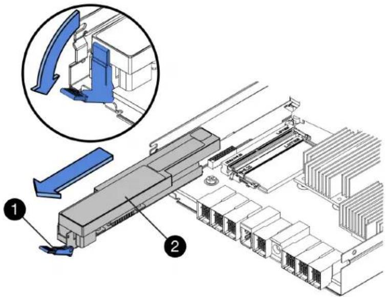
① Battery release latch Battery
2
Step 5. Lift up on the battery, and slide it out of the controller canister.
Step 6. Follow the appropriate procedures for your location to recycle or dispose of the failed battery.
To comply with International Air Transport Association (IATA) regulations, never ship a lithium battery by air unless it is installed within the controller shelf.
Go to "Install new battery" on page 110.
Install new battery
You install a new battery into the controller canister to replace the failed one.
Step 1: Install new battery
Install a new battery when the old one has failed.
Before you begin
- You have the removed failed battery from the controller canister.
- You have the replacement battery.
Step 1. Unpack the new battery, and set it on a flat, static-free surface.
Important: To comply with IATA safely regulations, replacement batteries are shipped with a state of charge (SoC) of 30 percent or less. When you reapply power, keep in mind that write caching will not resume until the replacement battery is fully charged and it has completed its initial learn cycle.
Step 2. Orient the controller canister so that the slot for the battery faces toward you.
Step 3. Insert the battery into the controller canister at a slight downward angle. You must insert the metal flange at the front of the battery into the slot on the bottom of the controller canister and slide the top of the battery beneath the small alignment pin on the left side of the canister.
Step 4. Move the battery latch up to secure the battery. When the latch clicks into place, the bottom of the latch hooks into a metal slot on the chassis.

| 1 Battery release latch Battery | 2 |
Step 5. Turn the controller canister over to confirm that the battery is installed correctly.
Attention: Possible hardware damage – The metal flange at the front of the battery must be completely inserted into the slot on the controller canister (as shown in the first figure). If the battery is not installed correctly (as shown in the second figure), the metal flange might contact the controller board, causing damage to the controller when you apply power.
- Correct – The battery's metal flange is completely inserted in the slot on the controller:

natural_image
Close-up of a mechanical component with a highlighted metal bracket (no visible text or symbols)- Incorrect – The battery's metal flange is not inserted into the slot on the controller:

natural_image
Close-up of mechanical components with a red-circled bracket and hexagonal nuts (no visible text or symbols)Go to "Step 2: Re-install controller canister" on page 112.
Step 2: Re-install controller canister
Reinstall the controller canister into the controller shelf after installing the new battery.
Step 1. Reinstall the cover on the controller canister by sliding the cover from back to front until the button clicks.
Step 2. Turn the controller canister over, so that the removable cover faces down.
Step 3. With the cam handle in the open position, slide the controller canister all the way into the controller shelf.

Figure 18. Example of the 2U model

Figure 19. Example of the 4U model
| 1 Controller canister Cam handle | 2 |
Step 4. Move the cam handle to the left to lock the controller canister in place.
Step 5. Reconnect all the cables.
Go to "Complete battery replacement" on page 113.
Complete battery replacement
If you have a two-controller configuration, you place the affected controller online and confirm that all components are working correctly. Then, you can collect support data and resume operations.
Place controller online
Place the controller online to confirm the storage array is working correctly. Then, you can collect support data and resume operations.
Perform this task only if your storage array has two controllers.
Step 1. As the controller boots, check the controller LEDs and the seven-segment display.
Note: The figure shows an example controller canister. Your controller might have a different number and a different type of host ports.
When communication with the other controller is reestablished:
- The seven-segment display shows the repeating sequence OS, OL, blank to indicate that the controller is offline.
- The amber Attention LED remains lit.
- The Host Link LEDs might be on, blinking, or off, depending on the host interface.

| 1 Attention LED (amber) Seven-segment display | 2 |
| 3 Host Link LEDs |
Step 2. Bring the controller online using either ThinkSystem System Manager or the Enterprise Management Window's (EMW) script editor of ThinkSystem Storage Manager.
• To use ThinkSystem System Manager:
- Select Hardware.
- If the graphic shows the drives, select Show back of shelf.
- Select the controller you want to place online.
- Select Place Online from the context menu, and confirm that you want to perform the operation.
The system places the controller online.
• To use script editor in the EMW:
- Open the Enterprise Management Window (EMW) in ThinkSystem Storage Manager on your local host.
-
Select the storage array.
-
Select Tools → Execute Script.
-
Type one of the following commands in the text box. For controller A: set controller [a] availability=online; For controller B: set controller [b] availability=online;
-
Select Tools → Verify and Execute
The system places the controller online.
Step 3. When the controller is back online, confirm that its status is Optimal, and check the controller shelf's Attention LEDs.
If the status is not Optimal or if any of the Attention LEDs are on, confirm that all cables are correctly seated, and check that the battery and the controller canister are installed correctly. If necessary, remove and reinstall the controller canister and the battery.
Note: If you cannot resolve the problem, contact technical support.
Step 4. Collect support data for your storage array using ThinkSystem System Manager.
- Select Support → Support Center → Diagnostics.
- Select Collect Support Data.
- Click Collect.
The file is saved in the Downloads folder for your browser with the name support-data.7z.
Your battery replacement is complete. You can resume normal operations.
Controllers
A controller consists of a board, firmware, and software. It controls the drives and implements the System Manager function. This section describes how to replace a controller in a controller shelf with two-controller configuration.
Overview and requirements
Before you replace a controller you need to be aware of certain requirements and considerations.
Controller overview
Each controller canister contains a controller card, a battery, and an optional host interface card (HIC). You can replace a failed controller.
Replace controller
When you replace a failed controller canister, you must remove the battery and HIC, if one is installed, from the original controller canister, and install them in the replacement controller canister.
You can determine if you have a failed controller canister in two ways:
- The Recovery Guru in ThinkSystem System Manager directs you to replace the controller canister.
- The amber Attention LED on the controller canister is on, indicating that the controller has a fault.

① Attention LED
Note: The figure shows an example controller canister; the host ports on your controller canister might be different.
Requirements for replacing controller
If you plan to replace a controller, keep the following requirements in mind.
- You must have a replacement controller canister with the same part number as the controller canister you are replacing.
- You have an ESD wristband, or you have taken other antistatic precautions.
- You must use labels to identify each cable that is connected to the controller canister.
- You must have a #1 Phillips screwdriver.
- You have installed ThinkSystem Storage Manager on a management station, so you can use the storage array's command line interface (CLI). If this software has not yet been installed, follow the instructions in the "Windows express configuration" on page 46, "VMware express configuration" on page 64, or "Linux express configuration" on page 79 to download and install it.
Two-controller configuration
If the controller shelf has two controllers, you can replace a controller canister while your storage array is powered on and performing host I/O operations, as long as the following conditions are true:
- The second controller canister in the shelf has Optimal status.
- The OK to remove field in the Details area of the Recovery Guru in ThinkSystem System Manager displays Yes, indicating that it is safe to remove this component.
Replace a controller
The following replacement procedure is based on the scenario that your storage array is a two-controller configuration. Each controller canister contains a controller card, a battery, and an optional host interface card (HIC). When you replace a controller canister, you must remove the battery and HIC, if one is installed, from the original controller canister, and install them in the replacement controller canister.
Prepare to replace controller
You prepare to replace a controller canister by verifying that the replacement controller canister has the correct FRU part number, backing up the configuration, and collecting support data. If the controller is still online, you must take it offline.
This task describes how to prepare to replace a controller canister in a controller shelf with two controllers.
Perform this task only if your storage array has two controllers.
Step 1. Unpack the new controller canister, and set it on a flat, static-free surface. Save the packing materials to use when shipping the failed controller canister.
Step 2. Locate the MAC address and FRU part number labels on the back of the controller canister.

① MAC address: The MAC address for management port 1 ("P1"). If you used DHCP to obtain the original controller's IP address, you will need this address to connect to the new controller.
② FRU part number: This number must match the replacement part number for the currently installed controller.
Step 3. From ThinkSystem System Manager, locate the replacement part number for the controller canister you are replacing. When a controller has a fault and needs to be replaced, the replacement part number is displayed in the Details area of the Recovery Guru. If you need to find this number manually, follow these steps:
a. Select Hardware.
b. Locate the controller shelf, which is marked with the controller icon
c. Click the controller icon.
d. Select the controller, and click Next.
e. On the Base tab, make a note of the Replacement Part Number for the controller.
Step 4. Confirm that the replacement part number for the failed controller is the same as the FRU part number for the replacement controller.
Attention: Possible loss of data access – If the two part numbers are not the same, do not attempt this procedure. In addition, if the failed controller canister includes a host interface card (HIC), you must install that HIC into the new controller canister. The presence of mismatched controllers or HICs will cause the new controller to lock down when you bring it online.
Step 5. Back up the storage array's configuration database.
If a problem occurs when you remove a controller, you can use the saved file to restore your configuration.
a. Open the Enterprise Management Window (EMW) for ThinkSystem Storage Manager on your management station.
b. Select the storage array.
c. Select Tools → Execute Script.
d. Type the following command in the text box.
save storageArray dbmDatabase sourceLocation=onboard contentType=all file="filename";
In this command, filename is the file path and file name to which you want to save the database. Enclose the file name in double quotation marks (" " ). For example: file="C:\Program Files\CLI\logs\dbmdata.zip"
This command does not automatically append a file extension to the saved file. You must specify a file extension when entering the file name.
e. Select Tools → Verify and Execute.
Note: If you have an untrusted certificate, you may need to accept the Security Exception.
Step 6. Collect support data for your storage array using ThinkSystem System Manager.
- Select Support → Support Center → Diagnostics.
- Select Collect Support Data.
- Click Collect.
The file is saved in the Downloads folder for your browser with the name support-data.7z.
Step 7. If the controller is not already offline, take it offline now using either ThinkSystem System Manager or the Enterprise Management Window's (EMW) script editor of ThinkSystem Storage Manager.
• To use ThinkSystem System Manager:
- Select Hardware.
- If the graphic shows the drives, select Show back of shelf to show the controllers.
- Select the controller that you want to place offline.
- From the context menu, select Place offline, and confirm that you want to perform the operation.
Note: If you are accessing ThinkSystem System Manager using the controller you are attempting to take offline, a System Manager Unavailable message is displayed. Select Connect to an alternate network connection to automatically access ThinkSystem System Manager using the other controller.
• To use script editor in the EMW:
- Open the Enterprise Management Window (EMW) in ThinkSystem Storage Manager on your local host.
- Select the storage array.
- Select Tools → Execute Script.
- Type one of the following commands in the text box. For controller A: set controller [a] availability=offline; For controller B: set controller [b] availability=offline;
- Select Tools → Verify and Execute.
The system attempts to take the controller offline.
Step 8. Wait for System Manager to update the controller's status to offline.
Attention: Do not begin any other operations until after the status has been updated.
Step 9. Select Recheck from the Recovery Guru, and confirm that the OK to remove field in the Details area displays Yes, indicating that it is safe to remove this component.
Go to "Remove failed controller" on page 118.
Remove failed controller
You remove a controller canister to replace the failed canister with a new one. Perform this task only if your storage array has two controllers.
Step 1: Remove controller canister
Remove the failed controller canister so you can replace it with a new one.
Before you begin
- You must use labels to identify each cable that is connected to the controller canister.
- You must have a #1 Phillips screwdriver.
- You have an ESD wristband, or you have taken other antistatic precautions.
Step 1. Put on an ESD wristband or take other antistatic precautions.
Step 2. Label each cable that is attached to the controller canister.
Step 3. Disconnect all the cables from the controller canister.
Attention: To prevent degraded performance, do not twist, fold, pinch, or step on the cables.
Step 4. If the controller canister has a HIC that uses SFP+ transceivers, remove the SFPs. Because you must remove the HIC from the failed controller canister, you must remove any SFPs from the HIC ports. However, you can leave any SFPs installed in the baseboard host ports. When you reconnect the cables, you can move those SFPs to the new controller canister.
Step 5. Confirm that the Cache Active LED on the back of the controller is off.
Step 6. Squeeze the latch on the cam handle until it releases, and then open the cam handle to the right to release the controller canister from the shelf.
The following figures are examples of a 2U and 4 U controller shelf:

Figure 20. 2U controller shelf

Figure 21. 4U controller shelf
| 1 Controller canister Cam handle | 2 |
Step 7. Using two hands and the cam handle, slide the controller canister out of the shelf.
Attention: Always use two hands to support the weight of a controller canister.
If you are removing the controller canister from a 2U controller shelf, a flap swings into place to block the empty bay, helping to maintain air flow and cooling.
Step 8. Turn the controller canister over, so that the removable cover faces up.
Step 9. Place the controller canister on a flat, static-free surface.
Go to "Step 2: Remove battery" on page 120.
Step 2: Remove battery
Remove the battery so you can install the new controller.
Step 1. Remove the controller canister's cover by pressing down on the button and sliding the cover off.
Step 2. Confirm that the green LED inside the controller (between the battery and the DIMMs) is off.
If this green LED is on, the controller is still using battery power. You must wait for this LED to go off before removing any components.

| 1 Internal Cache Active LED Battery | 2 |
Step 3. Locate the blue release latch for the battery.
Step 4. Unlatch the battery by pushing the release latch down and away from the controller canister.

① Battery release latch Battery
②
Step 5. Lift up on the battery, and slide it out of the controller canister.
Go to "Step 3: Remove host interface card" on page 121.
Step 3: Remove host interface card
If the controller canister includes a host interface card (HIC), you must remove the HIC from the original controller canister, so you can reuse it in the new controller canister.
Step 1. Using a #1 Phillips screwdriver, remove the screws that attach the HIC faceplate to the controller canister. There are four screws: one on the top, one on the side, and two on the front.

natural_image
Technical illustration of an electronic device chassis with internal components and a magnified inset showing a component detail (no text or symbols present)Step 2. Remove the HIC faceplate.
Step 3. Using your fingers or a Phillips screwdriver, loosen the three thumbscrews that secure the HIC to the controller card.
Step 4. Carefully detach the HIC from the controller card by lifting the card up and sliding it back.
Attention: Be careful not to scratch or bump the components on the bottom of the HIC or on the top of the controller card.

① Host interface card (HIC) Thumbscrews
2
Step 5. Place the HIC on a static-free surface.
Go to "Install new controller" on page 123.
Install new controller
You install a new controller canister to replace the failed one. Perform this task only if your storage array has two controllers.
Step 1: Install battery
You must install the battery into the replacement controller canister. You can install the battery that you removed from the original controller canister or install a new battery that you ordered.
Before you begin
- You have the battery from the original controller canister.
- You have the replacement controller canister.
Step 1. Turn the replacement controller canister over, so that the removable cover faces up.
Step 2. Press down on the cover button, and slide the cover off.
Step 3. Orient the controller canister so that the slot for the battery faces toward you.
Step 4. Insert the battery into the controller canister at a slight downward angle. You must insert the metal flange at the front of the battery into the slot on the bottom of the controller canister and slide the top of the battery beneath the small alignment pin on the left side of the canister.
Step 5. Move the battery latch up to secure the battery. When the latch clicks into place, the bottom of the latch hooks into a metal slot on the chassis.

| 1 Battery release latch Battery | 2 |
Step 6. Turn the controller canister over to confirm that the battery is installed correctly.
Attention: Possible hardware damage – The metal flange at the front of the battery must be completely inserted into the slot on the controller canister (as shown in the first figure). If the battery is not installed correctly (as shown in the second figure), the metal flange might contact the controller board, causing damage to the controller when you apply power.
- Correct – The battery's metal flange is completely inserted in the slot on the controller:

natural_image
Close-up of a mechanical component with a green-labeled bracket and bolted features (no visible text or symbols)- Incorrect – The battery's metal flange is not inserted into the slot on the controller:

natural_image
Close-up of a mechanical component with a red-circled bracket and hexagonal nuts (no visible text or symbols)Go to "Step 2: Install host interface card" on page 124.
Step 2: Install host interface card
If you removed a HIC from the original controller canister, you must install that HIC in the new controller canister.
Before you begin
- You must have a replacement controller canister with the same part number as the controller canister you are replacing.
- You must have a #1 Phillips screwdriver.
- You have an ESD wristband, or you have taken other antistatic precautions.
Step 1. Using a #1 Phillips screwdriver, remove the four screws that attach the blank faceplate to the replacement controller canister, and remove the faceplate.
Step 2. Align the three thumbscrews on the HIC with the corresponding holes on the controller, and align the connector on the bottom of the HIC with the HIC interface connector on the controller card. Be careful not to scratch or bump the components on the bottom of the HIC or on the top of the controller card.
Step 3. Carefully lower the HIC into place, and seat the HIC connector by pressing gently on the HIC.
Attention: Possible equipment damage – Be very careful not to pinch the gold ribbon connector for the controller LEDs between the HIC and the thumbscrews.

① Host interface card (HIC) Thumbscrews
②
Step 4. Hand-tighten the HIC thumbscrews.Do not use a screwdriver, or you might over tighten the screws.
Step 5. Using a #1 Phillips screwdriver, attach the HIC faceplate you removed from the original controller canister to the new controller canister with four screws.
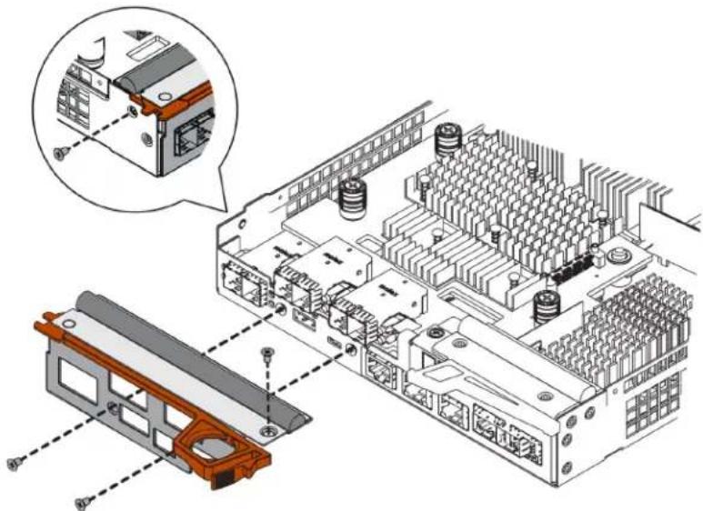
natural_image
Technical illustration of an electronic device chassis with a close-up inset showing internal components (no text or symbols)Go to "Step 3: Install new controller canister" on page 125.
Step 3: Install new controller canister
After installing the battery and the host interface card (HIC), if one was initially installed, you can install the new controller canister into the controller shelf.
Step 1. Reinstall the cover on the controller canister by sliding the cover from back to front until the button clicks.
Step 2. Turn the controller canister over, so that the removable cover faces down.
Step 3. With the cam handle in the open position, slide the controller canister all the way into the controller shelf.

Figure 22. 2U controller shelf

Figure 23. 4U controller shelf
| 1 Controller canister Cam handle | 2 |
Step 4. Move the cam handle to the left to lock the controller canister in place.
Step 5. Install the SFPs from the original controller in the host ports on the new controller, and reconnect all the cables. If you are using more than one host protocol, be sure to install the SFPs in the correct host ports.
Step 6. If the original controller used DHCP for the IP address, locate the MAC address on the label on the back of the replacement controller. Ask your network administrator to associate the DNS/network and IP address for the controller you removed with the MAC address for the replacement controller.
Note: If the original controller did not use DHCP for the IP address, the new controller will adopt the IP address of the controller you removed.
Go to "Complete controller replacement" on page 127.
Complete controller replacement
You complete the controller replacement by placing the controller online and confirming that the storage array is working correctly. Then, you can collect support data and resume operations.
Step 1. As the controller boots, check the controller LEDs and the seven-segment display.
When communication with the other controller is reestablished:
- The seven-segment display shows the repeating sequence OS, OL, blank to indicate that the controller is offline.
- The amber Attention LED remains on.
- The Host Link LEDs might be on, blinking, or off, depending on the host interface.

| 1 Attention LED (amber) Seven-segment display | 2 |
| 3 Host Link LEDs |
Step 2. Check the codes on the controller's seven-segment display as it comes back online. If the display shows one of the following repeating sequences, immediately remove the controller.
• OE, L0, blank (mismatched controllers)
• OE, L6, blank (unsupported HIC)
Attention: Possible loss of data access – If the controller you just installed shows one these codes, and the other controller is reset for any reason, the second controller could also lock down.
Step 3. When the controller is back online, confirm that its status is Optimal and check the controller shelf's Attention LEDs. If the status is not Optimal or if any of the Attention LEDs are on, confirm that all cables are correctly seated and the controller canister is installed correctly. If necessary, remove and reinstall the controller canister.
Note: If you cannot resolve the problem, contact technical support.
Step 4. If required, redistribute all volumes back to their preferred owner.
a. Select Storage → Volumes.
b. Select More → Redistribute volumes.
Step 5. Click Hardware → Support → Upgrade Center to ensure that the latest version of ThinkSystem SAN OS software (controller firmware) is installed. As needed, install the latest version.
Step 6. Collect support data for your storage array using ThinkSystem System Manager.
- Select Support → Support Center → Diagnostics.
- Select Collect Support Data.
- Click Collect.
The file is saved in the Downloads folder for your browser with the name support-data.7z.
Your controller replacement is complete. You can resume normal operations.
Power-fan canisters
Each 12-drive or 24-drive controller shelf or drive shelf includes two power supplies with integrated fans. These are referred to as power-fan canisters in ThinkSystem System Manager.
Overview and requirements
Before you replace a power-fan canister (power supply), you need to be aware of certain requirements and considerations.
Power supply overview
Each 12-drive or 24-drive controller shelf or drive shelf has two power-fan canisters that supply a redundant power source and adequate cooling.
The following shelves contain two power supplies (power-fan canisters):
• DE2000 controller shelf
• DE4000 controller shelf (2U)
• DE6000 controller shelf (2U)
- DE120S drive shelf
- DE240S drive shelf
The following figure shows an example 2U controller shelf with two power supplies (power-fan canisters). The DE120S and DE240S drive shelves are identical, but they include I/O modules (IOMs) instead of controller canisters.

①Controller shelf with two power supplies (power-fan canisters) below the controller canisters.
Requirements for replacing a power supply
If you plan to replace a power supply, keep the following requirements in mind.
- You must have a replacement power supply (power-fan canister) that is supported for your controller shelf or drive shelf model.
- You have an ESD wristband, or you have taken other antistatic precautions.
-
You can replace a power supply (power-fan canister) while your storage array is powered on and performing host I/O operations, as long as the following conditions are true:
-
The second power supply (power-fan canister) in the shelf has an Optimal status.
- The OK to remove field in the Details area of the Recovery Guru in ThinkSystem System Manager displays Yes, indicating that it is safe to remove this component.
Attention: If the second power supply (power-fan canister) in the shelf does not have Optimal status or if the Recovery Guru indicates that it is not OK to remove the power-fan canister, contact technical support.
Replace power supply (12-drive or 24-drive)
Each 12-drive or 24-drive controller shelf or drive shelf includes two power supplies with integrated fans. These are referred to as power-fan canisters in ThinkSystem System Manager. If a power-fan canister fails, you must replace it as soon as possible to ensure that the shelf has a redundant power source and adequate cooling.
Prepare to replace power supply
You prepare to replace a power supply in a 12-drive or 24-drive controller shelf or drive shelf by collecting support data about your storage array and locating the failed component. The power supply is referred to as a power-fan canister in ThinkSystem System Manager.
Before you begin
- You have reviewed the details in the Recovery Guru to confirm that there is an issue with the power supply. Select Recheck from the Recovery Guru to ensure no other items must be addressed first.
- You have checked that the amber Attention LED on the power supply is on, indicating that the power supply or its integrated fan has a fault. Contact technical support for assistance if both power supplies in the shelf have their amber Attention LEDs on.
This task describes how to prepare to replace a power supply for the following controller shelves:
• DE2000 controller shelf
• DE4000 controller shelf (2U)
• DE6000 controller shelf (2U)
- DE120S drive shelf
- DE240S drive shelf
You can replace a power supply while your storage array is powered on and performing host I/O operations, as long as the second power supply in the shelf has an Optimal status and the OK to remove field in the Details area of the Recovery Guru in ThinkSystem System Manager displays Yes.
Step 1. Collect support data for your storage array using ThinkSystem System Manager.
- Select Support → Support Center → Diagnostics.
- Select Collect Support Data.
- Click Collect.
The file is saved in the Downloads folder for your browser with the name support-data.7z.
Step 2. From ThinkSystem System Manager, determine which power supply has failed. You can find this information in the Details area of the Recovery Guru, or you can review the information displayed for the shelf.
a. Select Hardware.
b. Look at the power 📁 and fan Icons to the right of the Shelf drop-down lists to determine which shelf has the failed power supply. If a component has failed, either or both of these icons are red.
c. When you find the shelf with a red icon, select Show back of shelf.
d. Select either power supply.
e. On the Power Supplies and Fans tabs, look at the statuses of the power-fan canisters, the power supplies, and the fans to determine which power supply must be replaced. A component with a Failed status must be replaced.
Attention: If the second power supply canister in the shelf does not have Optimal status, do not attempt to hot-swap the failed power supply. Instead, contact technical support for assistance.
Step 3. From the back of the storage array, look at the Attention LEDs to locate the power supply you need to remove.
You must replace the power supply that has its Attention LED on.
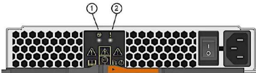
① Power LED: If it is solid green, the power supply is functioning correctly. If it is Off, the power supply failed, the AC switch is turned off, the AC power cord is not properly installed, or the AC power cord input voltage is not within margin (there is a problem at the source end of the AC power cord).
② Attention LED: If it is solid amber, the power supply or its integrated fan has a fault.
Go to "Remove failed power supply" on page 130.
Remove failed power supply
You remove a failed power supply so you can replace it with a new one. When you remove a power supply (referred to in ThinkSystem System Manager as a power-fan canister), you turn off power, disconnect the power cord, and slide the part out of the shelf.
Before you begin
- You have an ESD wristband, or you have taken other antistatic precautions.
Step 1. Unpack the new power supply, and set it on a level surface near the drive shelf. Save all packing materials for use when returning the failed power supply.
Step 2. Turn off the power supply and disconnect the power cables:
a. Turn off the power switch on the power supply.
b. Open the power cord retainer, and then unplug the power cord from the power supply.
c. Unplug the power cord from the power source.
Step 3. Squeeze the latch on the power supply cam handle, and then open the cam handle to fully release the power supply from the mid plane.
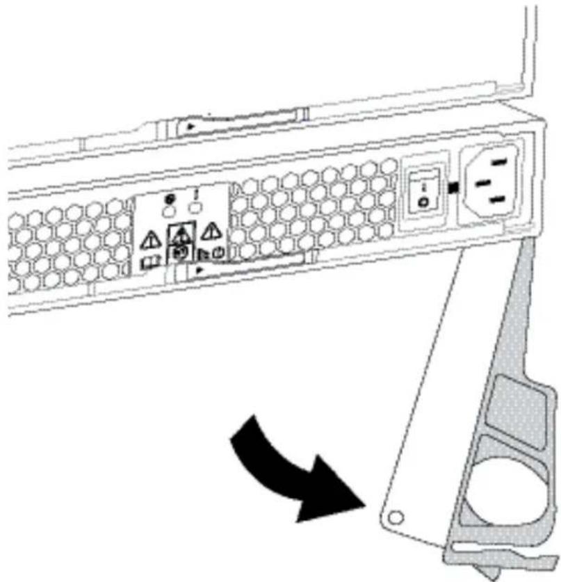
natural_image
Diagram of a server rack with hexagonal panel and control buttons, showing a black arrow indicating leftward motion (no text or symbols present)Step 4. Use the cam handle to slide the power supply out of the system.
Attention: When removing a power supply, always use two hands to support its weight.
As you remove the power supply, a flap swings into place to block the empty bay, helping to maintain air flow and cooling.
Go to "Install new power supply" on page 131.
Install new power supply
You install a new power supply to replace the failed one. When you install a power supply (referred to in ThinkSystem System Manager as a power-fan canister), you slide the part into the shelf, close the cam handle, reconnect the power cord, and reapply power.
Before you begin
- You have a replacement power supply that is supported for your controller shelf or drive shelf model.
- You have unpacked the replacement power supply.
Step 1. Make sure that the on/off switch of the new power supply is in the Off position.
Step 2. Using both hands, support and align the edges of the power supply with the opening in the system chassis, and then gently push the power supply into the chassis using the cam handle.
The power supplies are keyed and can only be installed one way.
Attention: Do not use excessive force when sliding the power supply into the system; you can damage the connector.
Step 3. Close the cam handle so that the latch clicks into the locked position and the power supply is fully seated.
Step 4. Reconnect the power supply cabling:
a. Reconnect the power cord to the power supply and the power source.
b. Secure the power cord to the power supply using the power cord retainer.
Step 5. Turn on the power to the new power supply canister.
Go to "Complete power supply replacement" on page 132.
Complete power supply replacement
You complete the power supply replacement by confirming that the new power supply (referred to in ThinkSystem System Manager as a power-fan canister) is working correctly. Then, you can gather support data and resume normal operations.
Step 1. On the new power supply, check that the green Power LED is on and the amber Attention LED is OFF.
Step 2. From the Recovery Guru in ThinkSystem System Manager, select Recheck to ensure the problem has been resolved.
Step 3. If a failed power supply is still being reported, repeat the steps in "Remove failed power supply" on page 130 and "Install new power supply" on page 131. If the problem continues to persist, contact technical support.
Step 4. Remove the antistatic protection.
Step 5. Collect support data for your storage array using ThinkSystem System Manager.
- Select Support → Support Center → Diagnostics.
- Select Collect Support Data.
- Click Collect.
The file is saved in the Downloads folder for your browser with the name support-data.7z.
Step 6. If you are instructed to return the failed part, follow all packaging instructions and use any packaging materials that are provided.
Your power supply replacement is complete. You can resume normal operations.
Canister
Each 60-drive controller shelf or drive shelf includes two power canisters for power redundancy and two fan canisters for cooling the controller shelf or drive shelf.
Overview and requirements
Before you replace a canister, you need to be aware of certain requirements and considerations.
Power canister overview
Each 60-drive controller shelf or drive shelf includes two power canisters for power redundancy.
The following shelves contain two power canisters:
• DE4000H controller shelf (4U)
• DE6000H controller shelf (4U)
- DE600S drive shelf
The following figure shows the back of a DE600S drive shelf with the two power canisters:

natural_image
Front view of a server rack unit with four fans and I2M12 modules (no visible text or symbols)The following figure shows a power canister:

Fan canister overview
Each 60-drive controller shelf or drive shelf includes two fan canisters.
You can replace a fan canister in the following 4U shelves:
• DE4000H controller shelf
• DE6000H controller shelf
- DE600S drive shelf
The following figure shows a fan canister:

natural_image
Two identical circular heat exchangers with radial heat sinks, mounted on a panel (no text or symbols visible)The following figure shows the back of a DE600S shelf with two fan canisters:
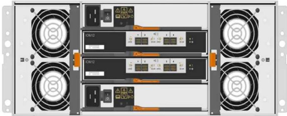
natural_image
Front view of a server rack unit with multiple I2M12 modules and fans, no visible text or symbols on the modules themselves.Attention: Possible equipment damage — If you replace a fan canister with the power turned on, you must complete the replacement procedure within 30 minutes to prevent the possibility of overheating the equipment.
Requirements for replacing a power canister
If you plan to replace a power supply, keep the following requirements in mind.
- You have a replacement power canister that is supported for your controller shelf or drive shelf model.
- You have one power canister that is installed and running.
- You have an ESD wristband, or you have taken other antistatic precautions.
- You can replace a power canister while your storage array is powered on and performing host I/O operations, as long as the following conditions are true:
- The other power canister in the shelf has Optimal status.
Note: While you perform the procedure, the other power canister supplies power to both fans to ensure that the equipment does not overheat.
- The OK to remove field in the Details area of the Recovery Guru in ThinkSystem System Manager displays Yes, indicating that it is safe to remove this component.
Attention: If the second power canister in the shelf does not have Optimal status or if the Recovery Guru indicates that it is not OK to remove the power canister, contact technical support.
Requirements for replacing a fan canister
If you plan to replace a fan canister, keep the following requirements in mind.
- You have a replacement fan canister (fan) that is supported for your controller shelf or drive shelf model.
- You have one fan canister that is installed and running.
- You have an ESD wristband, or you have taken other antistatic precautions.
- If you perform this procedure with the power turned on, you must complete it within 30 minutes to prevent the possibility of overheating the equipment.
- You can replace a fan canister while your storage array is powered on and performing host I/O operations, as long as the following conditions are true:
- The second fan canister in the shelf has an Optimal status.
- The OK to remove field in the Details area of the Recovery Guru in ThinkSystem System Manager displays Yes, indicating that it is safe to remove this component.
Attention: If the second fan canister in the shelf does not have Optimal status or if the Recovery Guru indicates that it is not OK to remove the fan canister, contact technical support.
Replace power canister
Each 60-drive controller shelf or drive shelf includes two power canisters for power redundancy. If a power canister fails, you must replace it as soon as possible to ensure that the shelf has a redundant power source.
Prepare to replace power canister
You prepare to replace a power canister in a 60-drive controller shelf or drive shelf by collecting support data about your storage array and locating the failed component.
- From ThinkSystem System Manager, review the details in the Recovery Guru to confirm that there is an issue with the power canister and select Recheck from the Recovery Guru to ensure no other items must be addressed first.
- Check that the amber Attention LED on the power canister is on, indicating that the canister has a fault. Contact technical support for assistance if both power canisters in the shelf have their amber Attention LEDs on.
This task describes how to prepare to replace a power canister for the following controller shelves:
• DE4000H controller shelf (4U)
• DE6000H controller shelf (4U)
- DE600S drive shelf
You can replace a power canister while your storage array is powered on and performing host I/O operations, as long as the second power canister in the shelf has an Optimal status and the OK to remove field in the Details area of the Recovery Guru in ThinkSystem System Manager displays Yes.
While you perform this task, the other power canister supplies power to both fans to ensure that the equipment does not overheat.
Step 1. Collect support data for your storage array using ThinkSystem System Manager.
- Select Support → Support Center → Diagnostics.
- Select Collect Support Data.
- Click Collect.
The file is saved in the Downloads folder for your browser with the name support-data.7z.
Step 2. From ThinkSystem System Manager, determine which power canister has failed.
a. Select Hardware.
b. Look at the power 📋 icon to the right of the Shelf drop-down lists to determine which shelf has the failed power canister. If a component has failed, this icon is red.
c. When you find the shelf with a red icon, select Show back of shelf.
d. Select either power canister or the red power icon.
e. On the Power Supplies tab, look at the statuses of the power canisters to determine which power canister must be replaced. A component with a Failed status must be replaced.
Attention: If the second power canister in the shelf does not have Optimal status, do not attempt to hot-swap the failed power canister. Instead, contact technical support for assistance.
Note: You can also find information about the failed power canister in the Details area of the Recovery Guru, or you can review the information displayed for the shelf, or you can review the Event Log under Support and filter by Component Type.
Step 3. From the back of the storage array, look at the Attention LEDs to locate the power canister you need to remove.
You must replace the power canister that has its Attention LED on.

① Power LEDs. If it is Solid green, the power canister is functioning correctly. If it is Off, the power canister failed, the AC switch is turned off, the AC power cord is not properly installed, or the AC power cord input voltage is not within margin (there is a problem at the source end of the AC power cord).
② Attention LED. If it is Solid amber, the power canister has a fault, or there is no input power to this power canister, but the other power canister is operating.
Go to "Remove failed power supply" on page 130.
Remove failed power canister
You remove a failed power canister so you can replace it with a new one. When you remove a power canister, you turn off power, disconnect the power cord, and slide the component out of the shelf.
- You have one power canister that is installed and running.
- You have an ESD wristband, or you have taken other antistatic precautions.
Step 1. Put on antistatic protection.
Step 2. Unpack the new power canister, and set it on a level surface near the shelf. Save all packing materials for use when returning the failed power canister.
Step 3. Turn off the power switch on the power canister that you need to remove.
Step 4. Open the power cord retainer of the power canister that you need to remove, and then unplug the power cord from the power canister.
Step 5. Press the orange latch on the power canister cam handle, and then open the cam handle to fully release the power canister from the mid plane.
Step 6. Use the cam handle to slide the power canister out of the shelf.
Attention: When removing a power canister, always use two hands to support its weight.
Go to "Install new power supply" on page 131.
Install new power canister
You install a new power canister to replace the failed one. When you install a power canister, you slide the component into the shelf, close the cam handle, reconnect the power cord, and reapply power.
- You have a replacement power canister that is supported for your controller shelf or drive shelf model.
- You have checked that the on/off switch of the new power canister is in the Off position.
Step 1. Using both hands, support and align the edges of the power canister with the opening in the system chassis, and then gently push the power canister into the chassis using the cam handle until it locks into place.
Attention: Do not use excessive force when sliding the power canister into the system; you can damage the connector.
Step 2. Close the cam handle so that the latch clicks into the locked position and the power canister is fully seated.
Step 3. Reconnect the power cord to the power canister, and secure the power cord to the power canister using the power cord retainer.
Step 4. Turn on the power to the new power canister.
Go to "Complete power canister replacement" on page 137.
Complete power canister replacement
You complete the power canister replacement by confirming that the new power canister is working correctly. Then, you can gather support data and resume normal operations.
Step 1. On the new power canister, check that the green Power LED is on and the amber Attention LED is OFF.
Step 2. From the Recovery Guru in ThinkSystem System Manager, select Recheck to ensure the problem has been resolved.
Step 3. If a failed power canister is still being reported, repeat the steps in "Remove failed power canister" on page 136 and "Install new power canister" on page 137. If the problem continues to persist, contact technical support.
Step 4. Remove the antistatic protection.
Step 5. Collect support data for your storage array using ThinkSystem System Manager.
- Select Support → Support Center → Diagnostics.
- Select Collect Support Data.
- Click Collect.
The file is saved in the Downloads folder for your browser with the name support-data.7z.
Step 6. If you are instructed to return the failed part, follow all packaging instructions and use any packaging materials that are provided.
Your power canister replacement is complete. You can resume normal operations.
Each 60-drive controller shelf or drive shelf includes two fan canisters. If a fan canister fails, you must replace it as soon as possible to ensure that the shelf has adequate cooling.
Prepare to replace fan canister
You prepare to replace a fan canister in a 60-drive controller shelf or drive shelf by collecting support data about your storage array and locating the failed component.
- From ThinkSystem System Manager, review the details in the Recovery Guru to confirm that there is an issue with the fan canister and select Recheck from the Recovery Guru to ensure no other items must be addressed first.
- Check that the amber Attention LED on the fan canister is on, indicating that the fan has a fault. Contact technical support for assistance if both fan canisters in the shelf have their amber Attention LEDs on.
This task describes how to prepare to replace a fan canister for the following controller shelves:
• DE4000H controller shelf (4U)
• DE6000H controller shelf (4U)
- DE600S drive shelf
Attention: Possible equipment damage — If you perform this procedure with the power turned on, you must complete it within 30 minutes to prevent the possibility of overheating the equipment.
Step 1. Collect support data for your storage array using ThinkSystem System Manager.
- Select Support → Support Center → Diagnostics.
- Select Collect Support Data.
- Click Collect.
The file is saved in the Downloads folder for your browser with the name support-data.7z.
Step 2. From ThinkSystem System Manager, determine which fan canister has failed.
a. Select Hardware.
b. Look at the fan icon to the right of the Shelf drop-down lists to determine which shelf has the failed fan canister. If a component has failed, this icon is red.
c. When you find the shelf with a red icon, select Show back of shelf.
d. Select either fan canister or the red fan icon.
e. On the Fans tab, look at the statuses of the fan canisters to determine which fan canister must be replaced. A component with a Failed status must be replaced.
Attention: If the second fan canister in the shelf does not have Optimal status, do not attempt to hot-swap the failed fan canister. Instead, contact technical support for assistance.
You can also find information about the failed fan canister in the Details area of the Recovery Guru, or you can review the Event Log under Support and filter by Component Type.
Step 3. From the back of the storage array, look at the Attention LEDs to locate the fan canister you need to remove.
You must replace the fan canister that has its Attention LED on.
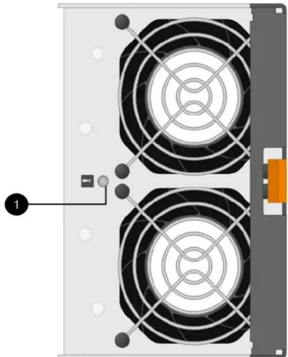
natural_image
Diagram of a dual-chamber electric fan or power supply unit with mounting holes and wiring (no text or symbols)① Attention LED. If this LED displays as Solid amber, then the fan has a fault.
Go to "Remove failed fan canister and install new one" on page 139.
Remove failed fan canister and install new one
You remove a failed fan canister so you can replace it with a new one.
- If you do not turn off the power to your storage array, ensure that you remove and replace the fan canister within 30 minutes to prevent the system from overheating.
- You have an ESD wristband, or you have taken other antistatic precautions.
Step 1. Unpack the new fan canister, and place it on a level surface near the shelf. Save all packing material for use when returning the failed fan.
Step 2. Press the orange tab to release the fan canister handle.
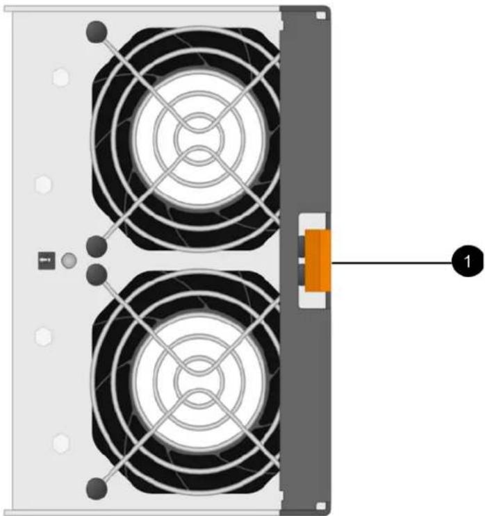
natural_image
Diagram of a server rack with two circular fans and an orange component, no text or symbols present① Tab that you press to release the fan canister handle.
Step 3. Use the fan canister handle to pull the fan canister out of the shelf.
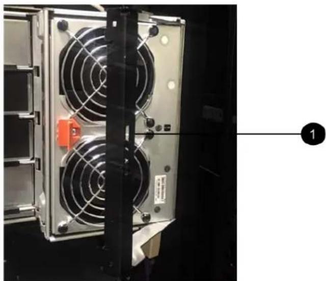
natural_image
Close-up of a server rack unit with two fans and a highlighted orange component, no visible text or symbols① Handle to pull the fan canister out.
Step 4. Slide the replacement fan canister all the way into the shelf, and then move the fan canister handle until it latches with the orange tab.
Go to "Complete fan canister replacement" on page 141.
Complete fan canister replacement
You complete the fan canister replacement by confirming that the new fan canister is working correctly. Then, you can gather support data and resume normal operations.
Step 1. Check the amber Attention LED on the new fan canister.
Note: After you replace the fan canister, the Attention LED stays on (solid amber) while the firmware checks that the fan canister was installed correctly. The LED goes off after this process is complete.
Step 2. From the Recovery Guru in ThinkSystem System Manager, select Recheck to ensure the problem has been resolved.
Step 3. If a failed fan canister is still being reported, repeat the steps in “Remove failed fan canister and install new one” on page 139. If the problem persists, contact technical support.
Step 4. Remove the antistatic protection.
Step 5. Collect support data for your storage array using ThinkSystem System Manager.
- Select Support → Support Center → Diagnostics.
- Select Collect Support Data.
- Click Collect.
The file is saved in the Downloads folder for your browser with the name support-data.7z.
Step 6. If you are instructed to return the failed part, follow all packaging instructions and use any packaging materials that are provided.
Your fan canister replacement is complete. You can resume normal operations.
Drives
A drive is an electromagnetic mechanical device that provides the physical storage media for data.
Overview and requirements
Before you replace a drive, you need to be aware of certain requirements and considerations.
Drives overview
You can replace a drive in either a 12-drive, 24-drive or 60-drive controller shelf or drive shelf.
12-drive or 24-drive shelves
The figures show how the drives are numbered in each type of shelf (the shelf's front bezel or end caps have been removed). Your system might look slightly different from the following figures.
Drive numbering in a 12-drive controller shelf or drive shelf

Drive numbering in a 24-drive controller shelf or drive shelf

60-drive shelves
The figures show how the drives are numbered in each type of shelf (the shelf's front bezel or end caps have been removed).
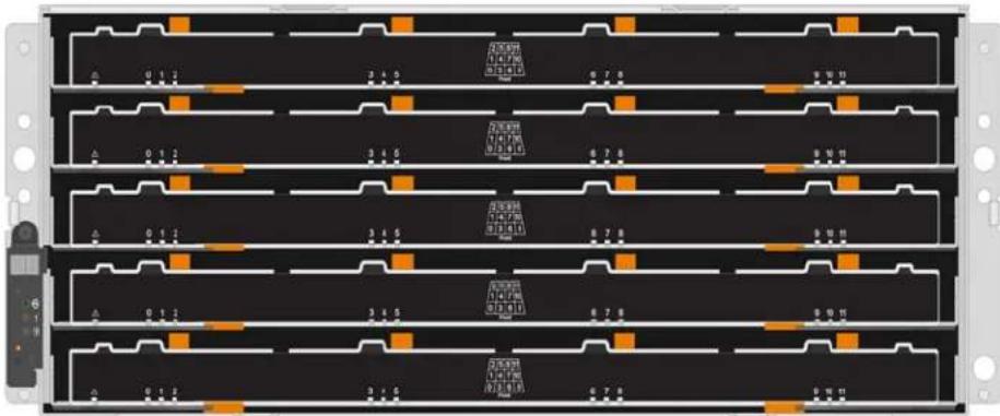
For both a DE4000H/DE6000H controller shelf drawer and a DE600S drive shelf drawer, drives are numbered from 0 to 11 in each drive drawer within the shelf.

Requirements for handling drives
The drives in your storage array are fragile. Improper drive handling is a leading cause of drive failure.
Follow these rules to avoid damaging the drives in your storage array:
• Prevent electrostatic discharge (ESD):
- Keep the drive in the ESD bag until you are ready to install it.
- Do not insert a metal tool or knife into the ESD bag. Open the ESD bag by hand or cut the top off with a pair of scissors.
- Keep the ESD bag and any packing materials in case you must return a drive later.
- Always wear an ESD wrist strap grounded to an unpainted surface on your storage enclosure chassis. If a wrist strap is unavailable, touch an unpainted surface on your storage enclosure chassis before handling the drive.
- Handle drives carefully:
- Always use two hands when removing, installing, or carrying a drive.
- Never force a drive into a shelf, and use gentle, firm pressure to completely engage the drive latch.
- Place drives on cushioned surfaces, and never stack drives on top of each other.
- Do not bump drives against other surfaces.
- Before removing a drive from a shelf, unlatch the handle and wait 30 seconds for the drive to spin down.
- Always use approved packaging when shipping drives.
- Avoid magnetic fields:
- Keep drives away from magnetic devices. Magnetic fields can destroy all data on the drive and cause irreparable damage to the drive circuitry.
Replace drive (12-drive, 24-drive or 60-drive)
The Recovery Guru in ThinkSystem System Manager monitors the drives in the storage array and can notify you of an impending drive failure or an actual drive failure. When a drive has failed, its amber Attention LED is on. You can hot-swap a failed drive while the storage array is receiving I/O.
Prepare to replace drive (12-drive or 24-drive)
You prepare to replace a drive by checking the Recovery Guru in ThinkSystem System Manager and completing any prerequisite steps. Then, you can locate the failed component.
Step 1. If the Recovery Guru in ThinkSystem System Manager has notified you of an impending drive failure, but the drive has not yet failed, follow the instructions in the Recovery Guru to fail the drive.
Step 2. If needed, use ThinkSystem System Manager to confirm you have a suitable replacement drive.
a. Select Hardware.
b. Select the failed drive on the shelf graphic.
c. Click the drive to display its context menu, and then select View settings.
d. Confirm that the replacement drive has a capacity equal to or greater than the drive you are replacing and that it has the features you expect. For example, do not attempt to replace a hard disk drive (HDD) with a solid-state disk (SSD). Similarly, if you are replacing a secure-capable drive, make sure the replacement drive is also secure-capable.
Step 3. If needed, use ThinkSystem System Manager to locate the drive within your storage array: From the drive's context menu, select Turn on locator light.
The drive's Attention LED (amber) blinks so you can identify which drive to replace.
Note: If you are replacing a drive in a shelf that has a bezel, you must remove the bezel to see the drive LEDs.
Go to "Remove failed drive (12-drive or 24-drive)" on page 144.
Remove failed drive (12-drive or 24-drive)
You remove a failed drive to replace it with a new one.
Before you begin
- You have an ESD wristband, or you have taken other antistatic precautions.
- You have reviewed the "Requirements for handling drives" on page 142 topic.
When you remove a drive, you must slide the drive partly out of the shelf and wait for the drive to spin down. Then, you can remove the drive completely.
To remove failed drive (12-drive or 24-drive), do the following:
Step 1. Unpack the replacement drive, and set it on a flat, static-free surface near the shelf. Save all packing materials.
Step 2. Press the release button on the failed drive.

- For drives in a 12-drive controller shelf or drive shelf, the release button is located at the left of the drive.
- For drives in a 24-drive controller shelf or drive shelf, the release button is located at the top of the drive.
The cam handle on the drive springs open partially, and the drive releases from the midplane.
Step 3. Open the cam handle, and slide out the drive slightly.
Step 4. Wait 30 seconds.
Step 5. Using both hands, remove the drive from the shelf.
Step 6. Place the drive on an antistatic, cushioned surface away from magnetic fields.
Step 7. Wait 30 seconds for the software to recognize that the drive has been removed.
Note: If you accidentally remove an active drive, wait at least 30 seconds, and then reinstall it. For the recovery procedure, refer to the storage management software.
Go to "Install new drive (12-drive or 24-drive)" on page 144.
Install new drive (12-drive or 24-drive)
You install a new drive to replace the failed one. Install the replacement drive as soon as possible after removing the failed drive. Otherwise, there is a risk that the equipment might overheat.
Before you begin
- You have a replacement drive that is supported by Lenovo for your controller shelf or drive shelf.
Step 1. Open the cam handle.
Step 2. Using two hands, insert the replacement drive into the open bay, firmly pushing until the drive stops.
Step 3. Slowly close the cam handle until the drive is fully seated in the midplane and the handle clicks into place.
The green LED on the drive comes on when the drive is inserted correctly.
Note: Depending on your configuration, the controller might automatically reconstruct data to the new drive. If the shelf uses hot spare drives, the controller might need to perform a complete reconstruction on the hot spare before it can copy the data to the replaced drive. This reconstruction process increases the time that is required to complete this procedure.
Go to "Complete drive replacement (12-drive, 24-drive or 60-drive)" on page 149.
Prepare to replace drive (60-drive)
You prepare to replace a drive by checking the Recovery Guru in ThinkSystem System Manager and completing any prerequisite steps. Then, you can locate the failed component.
Step 1. If the Recovery Guru in ThinkSystem System Manager has notified you of an impending drive failure, but the drive has not yet failed, follow the instructions in the Recovery Guru to fail the drive.
Step 2. If needed, use ThinkSystem System Manager to confirm you have a suitable replacement drive.
a. Select Hardware.
b. Select the failed drive on the shelf graphic.
c. Click the drive to display its context menu, and then select View settings.
d. Confirm that the replacement drive has a capacity equal to or greater than the drive you are replacing and that it has the features you expect. For example, do not attempt to replace a hard disk drive (HDD) with a solid-state disk (SSD). Similarly, if you are replacing a secure-capable drive, make sure the replacement drive is also secure-capable.
Step 3. If needed, use ThinkSystem System Manager to locate the drive within the storage array.
a. If the shelf has a bezel, remove it so you can see the LEDs.
b. From the drive's context menu, select Turn on locator light. The drive drawer's Attention LED (amber) blinks so you can open the correct drive drawer to identify which drive to replace.

① Attention LED
c. Unlatch the drive drawer by pulling on both levers.
d. Using the extended levers, carefully pull the drive drawer out until it stops.
e. Look at the top of the drive drawer to find the Attention LED in front of each drive.
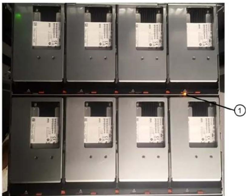
natural_image
Stacked industrial battery units with visible internal compartments and warning labels (no readable text or symbols)① Attention LED light on for the drive on the top right side
The drive drawer Attention LEDs are on the left side in front of each drive, with an attention icon on the drive handle just behind the LED.

natural_image
Close-up of a server rack with two panels, showing internal components and a warning symbol (no readable text or symbols)① Attention icon ② Attention LED
Go to "Remove failed drive (60-drive)" on page 146.
Remove failed drive (60-drive)
You remove a failed drive to replace it with a new one.
- You have an ESD wristband, or you have taken other antistatic precautions.
- You have reviewed the "Requirements for handling drives" on page 142 topic.
When you remove a drive, you must lift the drive partly out of the drawer and wait for the drive to spin down. Then, you can remove the drive completely.
Step 1. Unpack the replacement drive, and set it on a flat, static-free surface near the shelf. Save all packing materials for the next time you need to send a drive back.
Step 2. Release the drive drawer levers from the center of the appropriate drive drawer by pulling both towards the sides of the drawer.
Step 3. Carefully pull on the extended drive drawer levers to pull out the drive drawer to its full extension without removing it from the enclosure.
Step 4. Gently pull back the orange release latch that is in front of the drive you want to remove.
The cam handle on the drive springs open partially, and the drive is released from the drawer.

natural_image
Close-up of a computer drive bay with indicator lights and a warning symbol (no readable text or symbols)① Orange release latch
Step 5. Open the cam handle, and lift out the drive slightly.
Step 6. Wait 30 seconds.
Step 7. Use the cam handle to lift the drive from the shelf.

natural_image
3D diagram of an electronic device showing internal components and a housing (no text or symbols)Step 8. Place the drive on an antistatic, cushioned surface away from magnetic fields.
Step 9. Wait 30 seconds for the software to recognize that the drive has been removed.
Note: If you accidentally remove an active drive, wait at least 30 seconds, and then reinstall it. For the recovery procedure, refer to the storage management software.
Go to "Install new drive (60-drive)" on page 148.
Install new drive (60-drive)
You install a new drive to replace the failed one. Install the replacement drive as soon as possible after removing the failed drive. Otherwise, there is a risk that the equipment might overheat.
- You have a replacement drive that is supported by Lenovo for your controller shelf or drive shelf.
Attention: Possible loss of data access – When pushing the drive drawer back into the enclosure, never slam the drawer shut. Push the drawer in slowly to avoid jarring the drawer and causing damage to the storage array.
Step 1. Raise the cam handle on the new drive to vertical.
Step 2. Align the two raised buttons on each side of the drive carrier with the matching gap in the drive channel on the drive drawer.
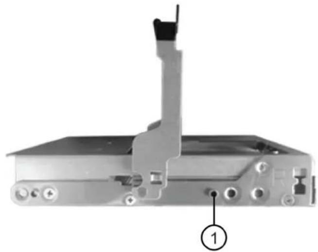
natural_image
Mechanical device component with labeled parts, showing a clamping mechanism and mounting bracket (no text or symbols beyond label)① Raised button on the right side of the drive carrier
Step 3. Lower the drive straight down, and then rotate the cam handle down until the drive snaps into place under the orange release latch.
Step 4. Carefully push the drive drawer back into the enclosure. Push the drawer in slowly to avoid jarring the drawer and causing damage to the storage array.
Step 5. Close the drive drawer by pushing both levers towards the center.
The green Activity LED for the replaced drive on the front of the drive drawer comes on when the drive is inserted correctly.
Depending on your configuration, the controller might automatically reconstruct data to the new drive. If the shelf uses hot spare drives, the controller might need to perform a complete reconstruction on the hot spare before it can copy the data to the replaced drive. This reconstruction process increases the time that is required to complete this procedure.
Go to "Complete drive replacement (12-drive, 24-drive or 60-drive)" on page 149.
Complete drive replacement (12-drive, 24-drive or 60-drive)
You complete the drive replacement to confirm that the new drive is working correctly.
Step 1. Check the Power LED and the Attention LED on the drive you replaced. (When you first insert a drive, its Attention LED might be on. However, the LED should go off within a minute.)
- Power LED is on or blinking, and the Attention LED is off: Indicates that the new drive is working correctly.
- Power LED is off: Indicates that the drive might not be installed correctly. Remove the drive, wait 30 seconds, and then reinstall it.
- Attention LED is on: Indicates that the new drive might be defective. Replace it with another new drive.
Step 2. If the Recovery Guru in ThinkSystem System Manager still shows an issue, select Recheck to ensure the problem has been resolved.
Step 3. If the Recovery Guru indicates that drive reconstruction did not start automatically, start reconstruction manually, as follows:
Note: Perform this operation only when instructed to do so by technical support or the Recovery Guru.
a. Select Hardware.
b. Click the drive that you replaced.
c. From the drive's context menu, select Reconstruct.
d. Confirm that you want to perform this operation. When the drive reconstruction completes, the volume group is in an Optimal state.
Step 4. As required, reinstall the bezel.
Step 5. If you are instructed to return the failed part, follow all packaging instructions and use any packaging materials that are provided.
Your drive replacement is complete. You can resume normal operations.
Host interface cards
A host interface card (HIC) can optionally be installed within a controller canister. The controller includes built-in host ports on the controller card itself, as well as host ports on the optional HIC. Host ports that are built into the controller are called baseboard host ports. Host ports that are built into the HIC are called HIC ports.
Overview and requirements
Before you add, upgrade or replace a host interface card, you need to be aware of certain requirements and considerations.
Host interface card overview
You can add, upgrade, or replace a host interface card (HIC) in the following controller shelves:
You controller comes with two 16 Gb/s FC or 10 Gb/s iSCSI baseboard host ports. Depending on the controller model, the following types of HICs in each controller model:
| Controller model Supported HIC | |
| DE2000 | Lenovo ThinkSystem DE2000 HIC, 10Gb Base-T, 2-ports |
| Lenovo ThinkSystem DE2000 HIC, 12Gb SAS, 2-ports | |
| DE4000 | Lenovo ThinkSystem DE4000 HIC, 10/25GbE iSCSI, 4-ports |
| Lenovo ThinkSystem DE4000 HIC, 12Gb SAS, 4-ports | |
| Lenovo ThinkSystem DE4000 HIC, 16Gb FC/10GbE iSCSI,4-ports | |
| Lenovo ThinkSystem DE4000 HIC, 32Gb FC, 4-ports | |
| DE6000 Lenovo ThinkSystem DE6000 | HIC, 10/25GbE iSCSI, 4-ports |
| Lenovo ThinkSystem DE6000 HIC, 12Gb SAS, 4-ports | |
| Lenovo ThinkSystem DE6000 HIC, 32Gb FC, 4-ports |
Important: If the controller has SFP+ (optical) baseboard ports and you add an SFP+ (optical) HIC, the new HIC ports usually default to the host protocol used by the baseboard host ports. For example, if you add a four-port SFP+ HIC to a controller that has FC baseboard ports, the new HIC ports should default to FC.
However, you must confirm the protocol of the new SFP+ HIC ports before connecting them to data hosts. In certain cases, you might need to apply a feature pack to convert the HIC ports from iSCSI to FC or from FC to iSCSI.
Add HIC
You can add host interface cards (HICs) to controller shelves that have only baseboard host ports. Adding HICs allows you to increase the number of host ports in your storage array and can provide additional host protocols. The following figures show a 2U and 4U controller shelf with two controller canisters before and after adding a HIC into each controller.

natural_image
Front view of a rack-mounted server rack with multiple ports and heat sinks (no visible text or labels)Figure 24. Without a HIC (2U)

natural_image
Front view of a server rack with four fans and multiple internal modules (no visible text or labels)Figure 25. Without a HIC (4U)

natural_image
Front view of a rack-mounted server rack with multiple ports and connectors, showing no visible text or symbols.Figure 26. With a HIC (2U)
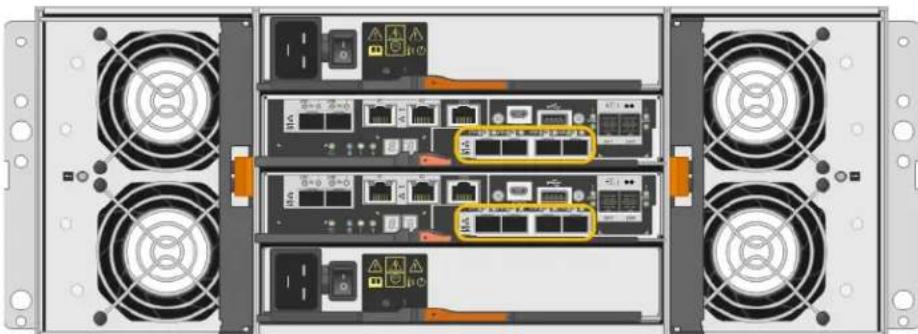
natural_image
Front view of a rack-mounted server rack with four fans and multiple ports (no visible text or labels)Figure 27. With a HIC (4U)
Note: The figures show example controller canisters with example HICs. You might have different types and numbers of baseboard ports and HIC ports.
Upgrade HIC
You change the host protocol by upgrading the HIC currently installed in a controller canister with a different type of HIC. The following figures show a 2U and 4U dual controller shelf before and after a HIC upgrade. The two HICs in the first figure have four SFP+ (optical) host ports, and the two HICs in the second figure have four SAS ports.

natural_image
Front view of a rack-mounted server rack with multiple ports and connectors (no visible text or labels)Figure 28. With two 4-port SFP+ (optical) HICs (2U)

natural_image
Back view of a server rack with multiple fans and internal network equipment (no visible text or labels)Figure 29. With two 4-port SFP+ (optical) HICs (4U)

natural_image
Front view of a network switch rack with multiple ports and connectors (no visible text or labels)Figure 30. With two 4-port SAS HICs (2U)

natural_image
Back view of a server rack with multiple drive fuses and internal network switches (no visible text or labels)Figure 31. With two 4-port SAS HICs (4U)
Note: The figures show example controller canisters with example HICs. You might have different types and numbers of baseboard ports and HIC ports.
Replace HIC
When you replace a failed host interface card (HIC) in a controller shelf, you must remove the controller canister, replace the HIC, and reinstall the controller canister. The following figure shows a 2U and 4U controller shelf with two controller canisters, each with a HIC.

natural_image
Front view of a rack-mounted server rack with multiple ports and connectors, highlighted by yellow circles (no visible text or symbols)Figure 32. HIC (2U)

natural_image
Back view of a server rack with multiple fans and internal network equipment (no visible text or labels)Figure 33. HIC (4U)
Note: The figures show example controller canisters with example HICs. You might have different types and numbers of baseboard ports and HIC ports.
Requirements for adding, upgrading or replacing a HIC
If you plan to add, upgrade, or replace a host interface card (HIC), keep the following requirements in mind.
- You have scheduled a downtime maintenance window for this procedure. The power must be off when you install HICs, so you cannot access data on the storage array until you have successfully completed this procedure. (In a two-controller configuration, this is because both controllers must have the same HIC configuration when they are powered on.)
- The HICs must be compatible with your controllers. The HICs installed in the two controller canisters must be identical. The presence of mismatched HICs causes the controller with the replacement HIC to lock down when you bring it online.
- You have all cables, transceivers, switches, and host bus adapters (HBAs) needed to connect the new host ports. For information about compatible hardware, refer to the DE Series Product Support Site or the the Lenovo ServerProven website.
- You have an ESD wristband, or you have taken other antistatic precautions.
- You have a #1 Phillips screwdriver.
- You have labels to identify each cable that is connected to the controller canister.
- You have installed ThinkSystem Storage Manager on a management station, so you can use the storage array's command line interface (CLI). If this software has not yet been installed, follow the instructions in
the "Windows express configuration" on page 46, "VMware express configuration" on page 64, or "Linux express configuration" on page 79 to download and install it.
Add host interface cards
You add host interface cards (HICs) to increase the number of host ports in your storage array and to provide additional host protocols. When you add HICs, you must power off the storage array, install the HIC, and reapply power. You can add HICs to controller canisters that only have baseboard host ports.
Prepare to add host interface cards
You prepare to add host interface cards by backing up the storage array's configuration database, collecting support data, and stopping host I/O operations. Then, you can power down the controller shelf.
Before you begin
- You have scheduled a downtime maintenance window for this procedure. The power must be off when you install HICs, so you cannot access data on the storage array until you have successfully completed this procedure. (In a two-controller configuration, this is because both controllers must have the same HIC configuration when they are powered on.)
Step 1. From the Home of ThinkSystem System Manager, ensure that the storage array has Optimal status.
If the status is not Optimal, use the Recovery Guru or contact technical support to resolve the problem. Do not continue with this procedure.
Step 2. Back up the storage array's configuration database.
If a problem occurs when you remove a controller, you can use the saved file to restore your configuration.
a. Open the Enterprise Management Window (EMW) for ThinkSystem Storage Manager on your management station.
b. Select the storage array.
c. Select Tools → Execute Script.
d. Type the following command in the text box.
save storageArray dbmDatabase sourceLocation=onboard contentType=all file="filename";
In this command, filename is the file path and file name to which you want to save the database. Enclose the file name in double quotation marks (" " ). For example: file="C:\Program Files\CLI\logs\dbmdata.zip"
This command does not automatically append a file extension to the saved file. You must specify a file extension when entering the file name.
e. Select Tools → Verify and Execute.
Note: If you have an untrusted certificate, you may need to accept the Security Exception.
Step 3. Collect support data for your storage array using ThinkSystem System Manager.
- Select Support → Support Center → Diagnostics.
- Select Collect Support Data.
- Click Collect.
The file is saved in the Downloads folder for your browser with the name support-data.7z.
Step 4. Ensure that no I/O operations are occurring between the storage array and all connected hosts. For example, you can perform these steps:
- Stop all processes that involve the LUNs mapped from the storage to the hosts.
- Ensure that no applications are writing data to any LUNs mapped from the storage to the hosts.
- Unmount all file systems associated with volumes on the array.
Note: The exact steps to stop host I/O operations depend on the host operating system and the configuration, which are beyond the scope of these instructions. If you are not sure how to stop host I/O operations in your environment, consider shutting down the host.
Attention: Possible data loss – If you continue this procedure while I/O operations are occurring, the host application might lose data because the storage array will not be accessible.
Step 5. If the storage array participates in a mirroring relationship, stop all host I/O operations on the secondary storage array.
Step 6. Wait for any data in cache memory to be written to the drives. The green Cache Active LED on the back of each controller is on when cached data needs to be written to the drives. You must wait for this LED to turn off.

① Cache Active LED
Step 7. From the Home page of ThinkSystem System Manager, select View Operations in Progress. Wait for all operations to complete before continuing with the next step.
Step 8. Power down the controller shelf.
a. Turn off both power switches on the controller shelf.
b. Wait for all LEDs on the controller shelf to turn off.
Go to "Add host interface card" on page 155.
Add host interface card
You add a host interface card (HIC) to increase the number of host ports in your storage array. If you are adding HICs to a two-controller configuration, repeat all steps to remove the second controller canister, install the second HIC, and reinstall the second controller canister.
Step 1: Remove controller canister
Remove the controller canister so you can add the new host interface card.
Before you begin
- You must use labels to identify each cable that is connected to the controller canister.
- You have an ESD wristband, or you have taken other antistatic precautions.
Step 1. Label each cable that is attached to the controller canister.
Step 2. Disconnect all the cables from the controller canister.
Attention: To prevent degraded performance, do not twist, fold, pinch, or step on the cables.
Step 3. Confirm that the Cache Active LED on the back of the controller is off.
The green Cache Active LED on the back of the controller is on when cached data needs to be written to the drives. You must wait for this LED to turn off before removing the controller canister.

① Cache Active LED
Step 4. Squeeze the latch on the cam handle until it releases, and then open the cam handle to the right to release the controller canister from the shelf.
The following figures are examples of a 2U and 4U controller shelf:
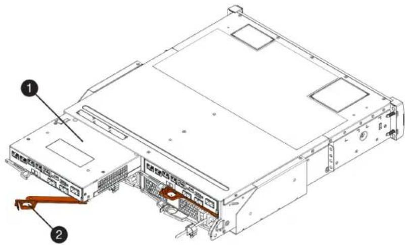
Figure 34. 2U controller shelf

Figure 35. 4U controller shelf
① Controller canister Cam handle
2
Step 5. Using two hands and the cam handle, slide the controller canister out of the shelf.
Attention: Always use two hands to support the weight of a controller canister.
If you are removing the controller canister from a 2U controller shelf, a flap swings into place to block the empty bay, helping to maintain air flow and cooling.
Step 6. Turn the controller canister over, so that the removable cover faces up.
Step 7. Place the controller canister on a flat, static-free surface.
Go to "Step 2: Install host interface card" on page 157.
Step 2: Install host interface card
Install the HIC to increase the number of host ports in your storage array.
Before you begin
- You have an ESD wristband, or you have taken other antistatic precautions.
- You have a #1 Phillips screwdriver.
- You have one or two HICs, based on whether you have one or two controllers in your storage array. The HICs must be compatible with your controllers.
Attention: Possible loss of data access – Never install a HIC in a controller canister if that HIC was designed for another DE Series controller. In a two-controller configuration, both controllers and both HICs must be identical. The presence of incompatible or mismatched HICs will cause the controllers to lock down when you apply power.
Step 1. Unpack the new HIC and the new HIC faceplate.
Step 2. Press the button on the cover of the controller canister, and slide the cover off.
Step 3. Confirm that the green LED inside the controller (by the DIMMs) is off.
If this green LED is on, the controller is still using battery power. You must wait for this LED to go off before removing any components.

① Internal Cache Active LED Battery
②
Step 4. Using a #1 Phillips screwdriver, remove the four screws that attach the blank faceplate to the controller canister, and remove the faceplate.
Step 5. Align the three thumbscrews on the HIC with the corresponding holes on the controller, and align the connector on the bottom of the HIC with the HIC interface connector on the controller card. Be careful not to scratch or bump the components on the bottom of the HIC or on the top of the controller card.
Step 6. Carefully lower the HIC into place, and seat the HIC connector by pressing gently on the HIC.
Attention: Possible equipment damage – Be very careful not to pinch the gold ribbon connector for the controller LEDs between the HIC and the thumbscrews.

① Host interface card (HIC) Thumbscrews
2
Step 7. Hand-tighten the HIC thumbscrews.Do not use a screwdriver, or you might over tighten the screws. Step 8. Using a #1 Phillips screwdriver, attach the new HIC faceplate to the controller canister with the four screws you removed previously.
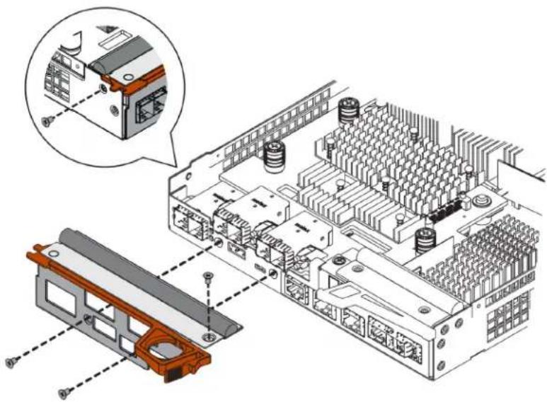
natural_image
Technical illustration of an electronic device chassis with internal components and a magnified inset showing a component detail (no text or symbols present)Go to "Step 3: Reinstall controller canister" on page 159.
Step 3: Reinstall controller canister
Reinstall the controller canister into the controller shelf after installing the new HIC.
Step 1. Turn the controller canister over, so that the removable cover faces down.
Step 2. With the cam handle in the open position, slide the controller canister all the way into the controller shelf.
The following figures are examples of a 2U and 4U controller shelf:
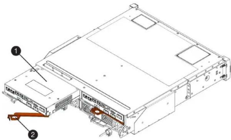
Figure 36. 2U controller shelf

Figure 37. 4U controller shelf
| 1 Controller canister Cam handle | 2 |
Step 3. Move the cam handle to the left to lock the controller canister in place.
Step 4. Reconnect all the cables you removed.
Attention: Do not connect data cables to the new HIC ports at this time.
Step 5. (Optional) If you are adding HICs to the second controller, repeat all steps to remove the second controller canister, install the second HIC, and reinstall the second controller canister.
Go to "Complete adding a host interface card" on page 161.
Complete adding a host interface card
You complete the process of adding a host interface card (HIC) by checking the controller LEDs and seven-segment display, and then confirming that the controller's status is Optimal.
Before you begin
- You have installed any new host hardware needed for the new host ports, such as switches or host bus adapters (HBAs).
- You have all cables, transceivers, switches, and host bus adapters (HBAs) needed to connect the new host ports. For information about compatible hardware, refer to the DE Series Product Support Site or the Lenovo Server Proven website.
- You have installed ThinkSystem Storage Manager on a management station, so you can use the storage array's command line interface (CLI). If this software has not yet been installed, follow the instructions in the "Windows express configuration" on page 46, "VMware express configuration" on page 64, or "Linux express configuration" on page 79 to download and install it.
Step 1. Turn on the two power switches at the back of the controller shelf.
- Do not turn off the power switches during the power-on process, which typically takes 90 seconds or less to complete.
- The fans in each shelf are very loud when they first start up. The loud noise during start-up is normal.
Step 2. As the controller boots, check the controller LEDs and seven-segment display.
- The seven-segment display shows the repeating sequence OS, Sd, blank to indicate that the controller is performing Start-of-day (SOD) processing. After a controller has successfully booted up, its seven-segment display should show the tray ID.
- The amber Attention LED on the controller turns on and then turns off, unless there is an error.
- The green Host Link LEDs remain off until you connect the host cables.
Note: The figure shows an example controller canister. Your controller might have a different number and a different type of host ports.

| 1 Attention LED (amber) Seven-segment display | 2 |
| 3 Host Link LEDs |
Step 3. From ThinkSystem System Manager, confirm that the controller's status is Optimal.
If the status is not Optimal or if any of the Attention LEDs are on, confirm that all cables are correctly seated, and check that the HIC and the controller canister are installed correctly. If necessary, remove and reinstall the controller canister and the HIC.
Note: If you cannot resolve the problem, contact technical support.
Step 4. If the new HIC ports require SFP+ transceivers, install these SFPs.
Step 5. If you installed a HIC with SFP+ (optical) ports, confirm the new ports have the host protocol you expect.
a. From ThinkSystem System Manager, select Hardware.
b. If the graphic shows the drives, click Show back of shelf.
c. Select the graphic for either Controller A or Controller B.
d. Select View settings from the context menu.
e. Select the Host Interfaces tab.
f. Click Show more settings.
g. Review the details shown for the HIC ports (the ports labelled e0x or 0x in HIC Location slot 1) to determine if you are ready to connect the host ports to the data hosts:
If the new HIC ports have the protocol you expect:
You are ready to connect the new HIC ports to the data hosts; go to the step below.
If the new HIC ports do not have the protocol you expect:
You must apply a software feature pack before you can connect the new HIC ports to the data hosts. See Converting the Protocol of Host Ports. Then, use the instructions in that document to connect the host ports to the data hosts and to resume operations.
Step 6. Connect the cables from the controller's host ports to the correct switch or data hosts.
Before you resume normal operations, ensure that you have completed the following steps:
- For iSCSI HIC adding or replacement:
- Ensure that the iSCSI SFPs or dual-protocol SFPs are installed.
- Attach cables to the SFPs, and confirm they are connected to the correct iSCSI switch or host.
- Power on the hosts.
- Configure the ISCSI hosts.
- Edit the host partition to update the iSCSI host port IDs.
- After the new iSCSI hosts reboot, use the applicable procedures on the hosts to register the volumes and to make them available to your operating system.
- For FC HIC adding or replacement.
- Ensure that the FC SFPs or dual-protocol SFPs are installed.
- Attach cables to the SFPs, and confirm they are connected to the correct FC switch or host.
- Power on the hosts.
- Configure the FC hosts.
- Edit the host partition to update the FC host port IDs.
- After the new FC hosts reboot, use the applicable procedures on the hosts to register the volumes and to make them available to your operating system. Depending on your operating system, two utilities are included with the storage management software (hot_add and SMdevices). These utilities help register the volumes with the hosts and also show the applicable device names for the volumes.
- You might need to use specific tools and options that are provided with your operating system to make the volumes available (that is, assign drive letters, create mount points, and so on). Refer to your host operating system documentation for details.
Upgrade host interface card
You upgrade a host interface card (HIC) to increase the number of host ports or to change host protocols. When you upgrade the HICs, you must power off the storage array, remove the existing HIC from each controller, install a new HIC, and reapply power.
Prepare to upgrade host interface cards
You prepare to upgrade host interface cards (HICs) by backing up the storage array's configuration database, collecting support data, and stopping host I/O operations. Then, you can power down the controller shelf.
Before you begin
- You have scheduled a downtime maintenance window for this procedure. The power must be off when you install HICs, so you cannot access data on the storage array until you have successfully completed this procedure. (In a two-controller configuration, this is because both controllers must have the same HIC configuration when they are powered on.)
- You have installed ThinkSystem Storage Manager on a management station, so you can use the storage array's command line interface (CLI).
Step 1. From the Home of ThinkSystem System Manager, ensure that the storage array has Optimal status.
If the status is not Optimal, use the Recovery Guru or contact technical support to resolve the problem. Do not continue with this procedure.
Step 2. Back up the storage array's configuration database.
If a problem occurs when you remove a controller, you can use the saved file to restore your configuration.
a. Open the Enterprise Management Window (EMW) for ThinkSystem Storage Manager on your management station.
b. Select the storage array.
c. Select Tools → Execute Script.
d. Type the following command in the text box.
save storageArray dbmDatabase sourceLocation=onboard contentType=all file="filename";
In this command, filename is the file path and file name to which you want to save the database. Enclose the file name in double quotation marks (" " ). For example: file="C:\Program Files\CLI\logs\dbmdata.zip"
This command does not automatically append a file extension to the saved file. You must specify a file extension when entering the file name.
e. Select Tools → Verify and Execute.
Note: If you have an untrusted certificate, you may need to accept the Security Exception.
Step 3. Collect support data for your storage array using ThinkSystem System Manager.
- Select Support → Support Center → Diagnostics.
- Select Collect Support Data.
- Click Collect.
The file is saved in the Downloads folder for your browser with the name support-data.7z.
Step 4. Ensure that no I/O operations are occurring between the storage array and all connected hosts. For example, you can perform these steps:
- Stop all processes that involve the LUNs mapped from the storage to the hosts.
- Ensure that no applications are writing data to any LUNs mapped from the storage to the hosts.
- Unmount all file systems associated with volumes on the array.
Note: The exact steps to stop host I/O operations depend on the host operating system and the configuration, which are beyond the scope of these instructions. If you are not sure how to stop host I/O operations in your environment, consider shutting down the host.
Attention: Possible data loss – If you continue this procedure while I/O operations are occurring, the host application might lose data because the storage array will not be accessible.
Step 5. If the storage array participates in a mirroring relationship, stop all host I/O operations on the secondary storage array.
Step 6. Wait for any data in cache memory to be written to the drives.
The green Cache Active LED on the back of each controller is on when cached data needs to be written to the drives. You must wait for this LED to turn off.

① Cache Active LED
Step 7. From the Home page of ThinkSystem System Manager, select View Operations in Progress. Wait for all operations to complete before continuing with the next step.
Step 8. Power down the controller shelf.
a. Turn off both power switches on the controller shelf.
b. Wait for all LEDs on the controller shelf to turn off.
Go to "Upgrade host interface card" on page 164.
Upgrade host interface card
You upgrade a host interface card (HIC) to increase the number of host ports or to change host protocols. If you are upgrading HICs in a two-controller configuration, repeat all steps to remove the other controller canister, remove the HIC, install the new HIC, and replace the second controller canister.
Step 1: Remove controller canister
Remove the controller canister so you can upgrade the new host interface card. When you remove a controller canister, you must disconnect all cables. Then, you can slide the controller canister out of the controller shelf.
Before you begin
- You have labels to identify each cable that is connected to the controller canister.
- You have an ESD wristband, or you have taken other antistatic precautions.
Step 1. Label each cable that is attached to the controller canister.
Step 2. Disconnect all the cables from the controller canister.
Attention: To prevent degraded performance, do not twist, fold, pinch, or step on the cables.
Step 3. If the HIC ports use SFP+ transceivers, remove them.
Depending on what type of HIC you are upgrading to, you might be able to reuse these SFPs.
Step 4. Confirm that the Cache Active LED on the back of the controller is off.
The green Cache Active LED on the back of the controller is on when cached data needs to be written to the drives. You must wait for this LED to turn off before removing the controller canister.

① Cache Active LED
Step 5. Squeeze the latch on the cam handle until it releases, and then open the cam handle to the right to release the controller canister from the shelf.
The following figures are examples of a 2U and 4U controller shelf:

Figure 38. 2U controller shelf

Figure 39. 4U controller shelf
| 1 Controller canister Cam handle | 2 |
Step 6. Using two hands and the cam handle, slide the controller canister out of the shelf.
Attention: Always use two hands to support the weight of a controller canister.
If you are removing the controller canister from a 2U controller shelf, a flap swings into place to block the empty bay, helping to maintain air flow and cooling.
Step 7. Turn the controller canister over, so that the removable cover faces up.
Step 8. Place the controller canister on a flat, static-free surface.
Go to "Step 2: Remove a host interface card" on page 167.
Step 2: Remove a host interface card
Remove the original host interface card so you can replace it with an upgraded one.
Before you begin
- You have a #1 Phillips screwdriver.
Step 1. Remove the controller canister's cover by pressing down on the button and sliding the cover off.
Step 2. Confirm that the green LED inside the controller (between the battery and the DIMMs) is off. If this green LED is on, the controller is still using battery power. You must wait for this LED to go off before removing any components.

① Internal Cache Active LED Battery
2
Step 3. Using a #1 Phillips screwdriver, remove the screws that attach the HIC faceplate to the controller canister. There are four screws: one on the top, one on the side, and two on the front.
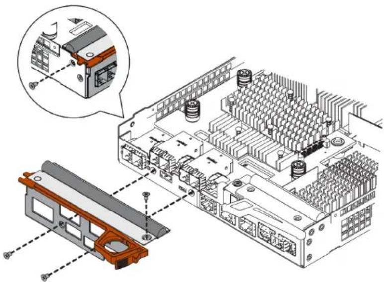
natural_image
Technical illustration of an electronic device chassis with internal components and a magnified inset showing a component detail (no text or symbols present)Step 4. Remove the HIC faceplate.
Step 5. Using your fingers or a Phillips screwdriver, loosen the three thumbscrews that secure the HIC to the controller card.
Step 6. Carefully detach the HIC from the controller card by lifting the card up and sliding it back.
Attention: Be careful not to scratch or bump the components on the bottom of the HIC or on the top of the controller card.

| 1 Host interface card (HIC) Thumbscrews | 2 |
Step 7. Place the HIC on a static-free surface.
Go to "Step 3: Install host interface card" on page 169.
Step 3: Install host interface card
Install the new HIC to increase the number of host ports in your storage array.
Before you begin
- You have an ESD wristband, or you have taken other antistatic precautions.
• You have a #1 Phillips screwdriver.
- You have one or two HICs, based on whether you have one or two controllers in your storage array. The HICs must be compatible with your controllers.
Attention: Possible loss of data access – Never install a HIC in a controller canister if that HIC was designed for another DE Series controller. In a two-controller configuration, both controllers and both HICs must be identical. The presence of incompatible or mismatched HICs will cause the controllers to lock down when you apply power.
Step 1. Unpack the new HIC and the new HIC faceplate.
Step 2. Using a #1 Phillips screwdriver, remove the four screws that attach the HIC faceplate to the controller canister, and remove the faceplate.

natural_image
Technical illustration of an electronic device chassis with internal components and a magnified inset showing a component detail (no text or symbols present)Step 3. Align the three thumbscrews on the HIC with the corresponding holes on the controller, and align the connector on the bottom of the HIC with the HIC interface connector on the controller card. Be careful not to scratch or bump the components on the bottom of the HIC or on the top of the controller card.
Step 4. Carefully lower the HIC into place, and seat the HIC connector by pressing gently on the HIC.
Attention: Possible equipment damage – Be very careful not to pinch the gold ribbon connector for the controller LEDs between the HIC and the thumbscrews.

① Host interface card (HIC) Thumbscrews
2
Step 5. Hand-tighten the HIC thumbscrews.Do not use a screwdriver, or you might over-tighten the screws.
Step 6. Using a #1 Phillips screwdriver, attach the new HIC faceplate to the controller canister with the four screws you removed previously.
Go to "Step 4: Reinstall controller canister" on page 170.
Step 4: Reinstall controller canister
Reinstall the controller canister into the controller shelf.
Step 1. Reinstall the cover on the controller canister by sliding the cover from back to front until the button clicks.
Step 2. Turn the controller canister over, so that the removable cover faces down.
Step 3. With the cam handle in the open position, slide the controller canister all the way into the controller shelf.
The following figures are examples of a 2U and 4U controller shelf:

Figure 40. 2U controller shelf

Figure 41. 4U controller shelf
| 1 Controller canister Cam handle | 2 |
Step 4. Move the cam handle to the left to lock the controller canister in place.
Step 5. Reconnect all the cables you removed.
Attention: Do not connect data cables to the new HIC ports at this time.
Step 6. (Optional) If you are upgrading HICs in a two-controller configuration, repeat all steps to remove the other controller canister, remove the HIC, install the new HIC, and replace the second controller canister.
Go to "Complete host interface card upgrade" on page 172.
Complete host interface card upgrade
You complete the process of upgrading a host interface card by checking the controller LEDs and seven-segment display and confirming that the controller's status is Optimal.
Before you begin
- You have installed any new host hardware needed for the new host ports, such as switches or host bus adapters (HBAs).
- You have all cables, transceivers, switches, and host bus adapters (HBAs) needed to connect the new host ports. For information about compatible hardware, refer to the DE Series Product Support Site or the the Lenovo ServerProven website.
Step 1. Turn on the two power switches at the back of the controller shelf.
- Do not turn off the power switches during the power-on process, which typically takes 90 seconds or less to complete.
- The fans in each shelf are very loud when they first start up. The loud noise during start-up is normal.
Step 2. As the controller boots, check the controller LEDs and seven-segment display.
- The seven-segment display shows the repeating sequence OS, Sd, blank to indicate that the controller is performing Start-of-day (SOD) processing. After a controller has successfully booted up, its seven-segment display should show the tray ID.
- The amber Attention LED on the controller turns on and then turns off, unless there is an error.
- The green Host Link LEDs remain off until you connect the host cables.
Note: The figure shows an example controller canister. Your controller might have a different number and a different type of host ports.

| 1 Attention LED (amber) Seven-segment display | 2 |
| 3 Host Link LEDs |
Step 3. From ThinkSystem System Manager, confirm that the controller's status is Optimal.
If the status is not Optimal or if any of the Attention LEDs are on, confirm that all cables are correctly seated, and check that the HIC and the controller canister are installed correctly. If necessary, remove and reinstall the controller canister and the HIC.
Note: If you cannot resolve the problem, contact technical support.
Step 4. If the new HIC ports require SFP+ transceivers, install these SFPs.
Step 5. Connect the cables from the controller's host ports to the data hosts.
The process of upgrading a host interface card in your storage array is complete. You can resume normal operations.
Replace host interface card
You replace a host interface card (HIC) that has failed. If two controllers are present, each controller must have identical HICs.
Prepare to replace host interface card
In a two-controller configuration, you must take the affected controller offline before you replace a host interface card (HIC).
Place controller offline
If you have a two-controller configuration, you must place the affected controller offline so you can safely remove the failed HIC. You must back up the configuration and collect support data first. Then, you can take the affected controller offline.
Before you begin
- Your storage array must have two controllers. The controller that you are not placing offline must be online (in the optimal state).
- Make sure that no volumes are in use or that you have a multipath driver installed on all hosts using these volumes.
- From ThinkSystem System Manager, review the details in the Recovery Guru to confirm that you have a failed HIC and to ensure no other items must be addressed before you can remove and replace the HIC.
Perform this task only if your storage array has two controllers.
Step 1. From the Details area of the Recovery Guru, determine which of the controller canisters has the failed HIC.
Step 2. Back up the storage array's configuration database.
If a problem occurs when you remove a controller, you can use the saved file to restore your configuration.
a. Open the Enterprise Management Window (EMW) for ThinkSystem Storage Manager on your management station.
b. Select the storage array.
c. Select Tools → Execute Script.
d. Type the following command in the text box.
save storageArray dbmDatabase sourceLocation=onboard contentType=all file="filename";
In this command, filename is the file path and file name to which you want to save the database. Enclose the file name in double quotation marks (" " ). For example: file="C:\Program Files\CLI\logs\dbmdata.zip"
This command does not automatically append a file extension to the saved file. You must specify a file extension when entering the file name.
e. Select Tools → Verify and Execute.
Note: If you have an untrusted certificate, you may need to accept the Security Exception.
Step 3. Collect support data for your storage array using ThinkSystem System Manager.
- Select Support → Support Center → Diagnostics.
- Select Collect Support Data.
- Click Collect.
The file is saved in the Downloads folder for your browser with the name support-data.7z.
Step 4. If the controller is not already offline, take it offline now using either ThinkSystem System Manager or the Enterprise Management Window's (EMW) script editor of ThinkSystem Storage Manager.
• To use ThinkSystem System Manager:
- Select Hardware.
- If the graphic shows the drives, select Show back of shelf to show the controllers.
- Select the controller that you want to place offline.
- From the context menu, select Place offline, and confirm that you want to perform the operation.
Note: If you are accessing ThinkSystem System Manager using the controller you are attempting to take offline, a System Manager Unavailable message is displayed. Select Connect to an alternate network connection to automatically access ThinkSystem System Manager using the other controller.
• To use script editor in the EMW:
- Open the Enterprise Management Window (EMW) in ThinkSystem Storage Manager on your local host.
- Select the storage array.
- Select Tools → Execute Script.
- Type one of the following commands in the text box. For controller A: set controller [a] availability=offline; For controller B: set controller [b] availability=offline;
- Select Tools → Verify and Execute.
The system attempts to take the controller offline.
Step 5. Wait for System Manager to update the controller's status to offline.
Attention: Do not begin any other operations until after the status has been updated.
Go to "Replace host interface card" on page 174.
Replace host interface card
You replace a host interface card (HIC) to replace the failed HIC with a new one. If you are replacing HICs in a two-controller configuration, repeat all steps to remove the second controller canister, install the second HIC, and reinstall the second controller canisters.
Step 1: Remove controller canister
You remove the controller canister so you can add the new host interface card (HIC). When you remove a controller canister, you must disconnect all cables. Then, you can slide the controller canister out of the controller shelf.
Before you begin
- You have scheduled a downtime maintenance window for this procedure. The power must be off when you install HICs, so you cannot access data on the storage array until you have successfully completed this procedure. (In a two-controller configuration, this is because both controllers must have the same HIC configuration when they are powered on.)
- You must use labels to identify each cable that is connected to the controller canister.
- You have an ESD wristband, or you have taken other antistatic precautions.
Step 1. Label each cable that is attached to the controller canister.
Step 2. Disconnect all the cables from the controller canister.
Attention: To prevent degraded performance, do not twist, fold, pinch, or step on the cables.
Step 3. Confirm that the Cache Active LED on the back of the controller is off.
The green Cache Active LED on the back of the controller is on when cached data needs to be written to the drives. You must wait for this LED to turn off before removing the controller canister.
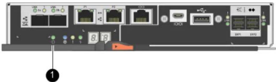
① Cache Active LED
Step 4. Squeeze the latch on the cam handle until it releases, and then open the cam handle to the right to release the controller canister from the shelf.
The following figures are examples of a 2U and 4U controller shelf:
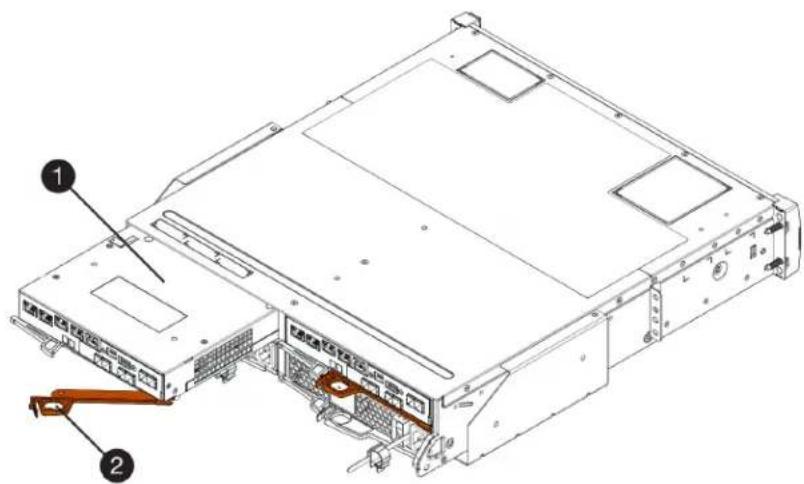
Figure 42. 2U controller shelf

Figure 43. 4U controller shelf
| 1 Controller canister Cam handle | 2 |
Step 5. Using two hands and the cam handle, slide the controller canister out of the shelf.
Attention: Always use two hands to support the weight of a controller canister.
If you are removing the controller canister from a 2U controller shelf, a flap swings into place to block the empty bay, helping to maintain air flow and cooling.
Step 6. Turn the controller canister over, so that the removable cover faces up.
Step 7. Place the controller canister on a flat, static-free surface.
Go to "Step 2: Install host interface card" on page 176.
Step 2: Install host interface card
You install a host interface card (HIC) to replace the failed one with a new HIC.
Before you begin
- You have an ESD wristband, or you have taken other antistatic precautions.
- You have a #1 Phillips screwdriver.
- You have one or two HICs, based on whether you have one or two controllers in your storage array. The HICs must be compatible with your controllers.
Attention: Possible loss of data access – Never install a HIC in a controller canister if that HIC was designed for another DE Series controller. In a two-controller configuration, both controllers and both HICs must be identical. The presence of incompatible or mismatched HICs will cause the controllers to lock down when you apply power.
Step 1. Unpack the new HIC and the new HIC faceplate.
Step 2. Press the button on the cover of the controller canister, and slide the cover off.
Step 3. Confirm that the green LED inside the controller (by the DIMMs) is off.
If this green LED is on, the controller is still using battery power. You must wait for this LED to go off before removing any components.

① Internal Cache Active LED Battery
②
Step 4. Using a #1 Phillips screwdriver, remove the four screws that attach the blank faceplate to the controller canister, and remove the faceplate.
Step 5. Align the three thumbscrews on the HIC with the corresponding holes on the controller, and align the connector on the bottom of the HIC with the HIC interface connector on the controller card. Be careful not to scratch or bump the components on the bottom of the HIC or on the top of the controller card.
Step 6. Carefully lower the HIC into place, and seat the HIC connector by pressing gently on the HIC.
Attention: Possible equipment damage – Be very careful not to pinch the gold ribbon connector for the controller LEDs between the HIC and the thumbscrews.
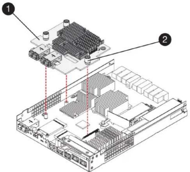
| 1 Host interface card (HIC) Thumbscrews | 2 |
Step 7. Hand-tighten the HIC thumbscrews.Do not use a screwdriver, or you might over-tighten the screws.
Step 8. Using a #1 Phillips screwdriver, attach the new HIC faceplate to the controller canister with the four screws you removed previously.
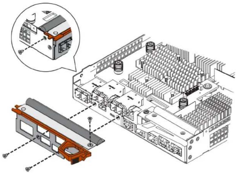
natural_image
Technical illustration of an electronic device chassis with internal components and a magnified inset showing a close-up view of the component (no text or symbols present)Go to "Step 3: Reinstall controller canister" on page 178
Step 3: Reinstall controller canister
After installing the host interface card (HIC), you reinstall the controller canister into the controller shelf.
Step 1. Turn the controller canister over, so that the removable cover faces down.
Step 2. With the cam handle in the open position, slide the controller canister all the way into the controller shelf.
The following figures are examples of a 2U and 4U controller shelf:

Figure 44. 2U controller shelf

Figure 45. 4U controller shelf
① Controller canister Cam handle
②
Step 3. Move the cam handle to the left to lock the controller canister in place.
Step 4. Reconnect all the cables you removed.
Attention: Do not connect data cables to the new HIC ports at this time.
Step 5. (Optional) If you are adding HICs to a two-controller configuration, repeat all steps to remove the second controller canister, install the second HIC, and reinstall the second controller canister.
Go to "Complete host interface card replacement" on page 180.
Complete host interface card replacement
In a two-controller configuration, you place the affected controller online and confirm that all components are working correctly. Then, you can collect support data and resume operations.
Place controller online
You bring the controller online to confirm the storage array is working correctly. Then, you can collect support data and resume operations.
Perform this task only if your storage array has two controllers.
Step 1. As the controller boots, check the controller LEDs and the seven-segment display.
Note: The figure shows an example controller canister. Your controller might have a different number and a different type of host ports.
When communication with the other controller is reestablished:
- The seven-segment display shows the repeating sequence OS, OL, blank to indicate that the controller is offline.
- The amber Attention LED remains lit.
- The Host Link LEDs might be on, blinking, or off, depending on the host interface.
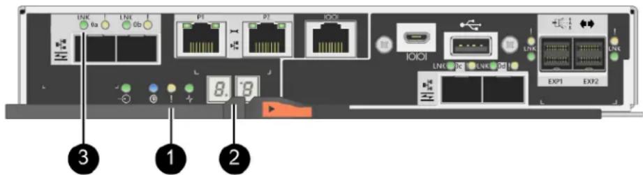
| 1 Attention LED (amber) Seven-segment display | 2 |
| 3 Host Link LEDs |
Step 2. Bring the controller online using either ThinkSystem System Manager or the Enterprise Management Window's (EMW) script editor of ThinkSystem Storage Manager.
• To use ThinkSystem System Manager:
- Select Hardware.
- If the graphic shows the drives, select Show back of shelf.
- Select the controller you want to place online.
- Select Place Online from the context menu, and confirm that you want to perform the operation.
The system places the controller online.
• To use script editor in the EMW:
- Open the Enterprise Management Window (EMW) in ThinkSystem Storage Manager on your local host.
- Select the storage array.
- Select Tools → Execute Script.
- Type one of the following commands in the text box.
For controller A: set controller [a] availability=online;
For controller B: set controller [b] availability=online;
5. Select Tools → Verify and Execute
The system places the controller online.
Step 3. Check the codes on the controller's seven-segment display as it comes back online. If the display shows one of the following repeating sequences, immediately remove the controller.
• OE, L0, blank (mismatched controllers)
• OE, L6, blank (unsupported HIC)
Attention: Possible loss of data access – If the controller you just installed shows one of these codes, and the other controller is reset for any reason, the second controller could also lock down.
Step 4. When the controller is back online, confirm that its status is Optimal, and check the controller shelf's Attention LEDs.
If the status is not Optimal or if any of the Attention LEDs are on, confirm that all cables are correctly seated, and check that the HIC and the controller canister are installed correctly. If necessary, remove and reinstall the controller canister and the HIC.
Note: If you cannot resolve the problem, contact technical support.
Step 5. Collect support data for your storage array using ThinkSystem System Manager.
- Select Support → Support Center → Diagnostics.
- Select Collect Support Data.
- Click Collect.
The file is saved in the Downloads folder for your browser with the name support-data.7z.
Step 6. If you are instructed to return the failed part, follow all packaging instructions and use any packaging materials that are provided.
Before you resume normal operations, ensure that you have completed the following steps:
- For iSCSI HIC adding or replacement:
- Ensure that the iSCSI SFPs or dual-protocol SFPs are installed.
- Attach cables to the SFPs, and confirm they are connected to the correct iSCSI switch or host.
- Power on the hosts.
- Configure the ISCSI hosts.
- Edit the host partition to update the iSCSI host port IDs.
- After the new iSCSI hosts reboot, use the applicable procedures on the hosts to register the volumes and to make them available to your operating system.
- For FC HIC adding or replacement.
- Ensure that the FC SFPs or dual-protocol SFPs are installed.
- Attach cables to the SFPs, and confirm they are connected to the correct FC switch or host.
- Power on the hosts.
- Configure the FC hosts.
- Edit the host partition to update the FC host port IDs.
-
After the new FC hosts reboot, use the applicable procedures on the hosts to register the volumes and to make them available to your operating system. Depending on your operating system, two utilities are included with the storage management software (hot_add and SMdevices). These utilities help register the volumes with the hosts and also show the applicable device names for the volumes.
-
You might need to use specific tools and options that are provided with your operating system to make the volumes available (that is, assign drive letters, create mount points, and so on). Refer to your host operating system documentation for details.
Host port protocol
You can convert the protocol of a host to a different protocol so that compatibility and communication can be established.
Overview and requirements
Learn about the baseboard host ports and the requirements you need to know about before converting the host protocol.
Host protocol overview
You can convert the host port protocol of the baseboard host ports in the controller shelf.
The following figure shows the back of a 2U/4Ucontroller that has two SFP+ (optical) baseboard host ports ① and four SFP+ (optical) HIC ports ②
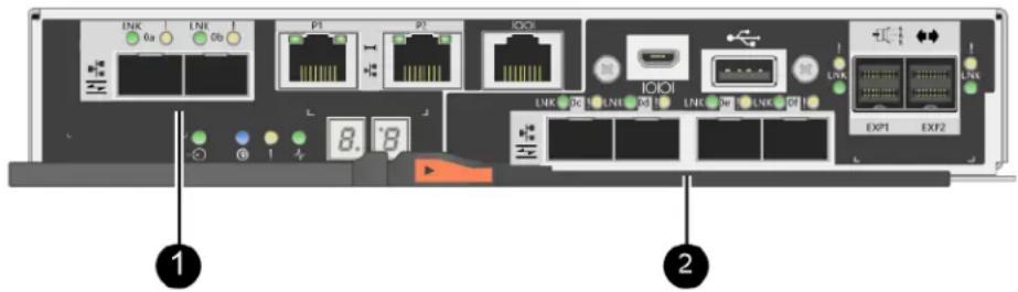
Note: A two-port HIC is also available.
Which host ports can you change
The controllers in your storage array might have different types of baseboard host ports and different types of HIC ports. The table shows which host ports can be changed with a feature pack.
| If you have... | You can change... | |
| These baseboard host ports... And these HIC ports... | ||
| Two SFP+ (optical) ports | None | Only the baseboard host ports |
| Two or four SAS ports Only the baseboard host ports | ||
| Two RJ-45 (base-T) ports Only the baseboard host ports | ||
| Four 32Gb FC ports Only the baseboard host ports | ||
| Four 10Gb or 25Gb iSCSI ports | Only the baseboard host ports | |
| Four 10Gb iSCSI or 16Gb FC ports | All of the ports (DE4000 only) | |
The baseboard host ports and the HIC ports can use the same host protocol or different host protocols.
Requirements for changing the host protocol
Learn about the requirements you need to keep in mind when changing the host port protocol.
- You have scheduled a downtime maintenance window for this procedure.
- You must stop host I/O operations when you perform the conversion, and you will not be able to access data on the storage array until you have successfully completed the conversion.
- You are using out-of-band management. (You cannot use in-band management to complete this procedure.)
- You have obtained the necessary hardware for the conversion. Your Lenovo Sales Representative can help you determine what hardware you need and help you order the correct parts.
- If you are attempting to change the baseboard host ports of your storage array, and it currently uses dual-protocol (also referred to as unified) SFP transceivers that you purchased from Lenovo, you do not need to change your SFP transceivers.
- Dual-protocol SFP transceivers support both FC (at 4 Gbps, 8 Gbps, 16 Gbps,) and iSCSI (at 10 Gbps), but they do not support 1 Gbps iSCSI. See “Determine whether you have dual-protocol SFPs” on page 187 to determine what type of SFP transceivers are installed.
Considerations for changing the host protocol
The considerations for changing the host protocol depend on the starting and ending protocols of the baseboard host ports and the HIC ports.
If you use a Mirroring feature or the Data Assurance (DA) feature, you must understand what happens to these features when you change the host port protocol.
Note: The following considerations apply only if you are converting a storage array that has already been in use. These considerations do not apply if you are converting a new storage array that does not yet have hosts and volumes defined.
Converting from FC to iSCSI
- If your configuration contains SAN Boot hosts connected to the FC baseboard ports, ensure that the configuration is supported on iSCSI. If it is not, you cannot convert the host protocol to iSCSI.
- The DA feature is not supported for iSCSI.
- If you are currently using DA and you want to convert FC host ports to iSCSI, you must disable DA on all volumes.
- If you do not deactivate DA before converting to iSCSI, the storage array will be out of compliance after the conversion.
- The Synchronous Mirroring feature is not supported for iSCSI.
- If you are currently using Synchronous Mirroring relationships and you want to convert FC host ports to iSCSI, you must deactivate Synchronous Mirroring.
- Refer to the online help for ThinkSystem System Manager to remove all synchronous mirrored pairs, which removes mirror relationships on the local storage array and on the remote storage array. In addition, follow the instructions in the online help to deactivate Synchronous Mirroring.
Attention: If you do not deactivate Synchronous Mirroring relationships before converting to iSCSI, your system will lose data access and data loss might occur.
- Asynchronous Mirroring requires both the local storage array and the remote storage array to use the same protocol.
- If you are currently using Asynchronous Mirroring and you want to convert all host ports from FC to iSCSI, you must deactivate Asynchronous Mirroring before applying the feature pack.
- Refer to the online help for ThinkSystem System Manager to delete all mirror consistency groups and remove all mirrored pairs from the local and remote storage arrays. In addition, follow the instructions in the online help to deactivate Asynchronous Mirroring.
Converting from iSCSI to FC
- Asynchronous Mirroring requires both the local storage array and the remote storage array to use the same protocol. If you are currently using Asynchronous Mirroring with the baseboard ports, you must deactivate Asynchronous Mirroring before changing the protocol.
- Refer to the online help for ThinkSystem System Manager to delete all mirror consistency groups and remove all mirrored pairs from the local and remote storage arrays. In addition, follow the instructions in the online help to deactivate Asynchronous Mirroring.
Converting from FC to FC/iSCSI
Mirroring considerations
- If a storage array used for mirroring currently has only FC ports, and you want to convert some of them to iSCSI, you must determine which ports are used for mirroring.
- You do not need to convert the ports on the local storage array and the remote storage array to the same protocol as long as both storage arrays have at least one active FC port after the conversion.
- If you plan to convert the ports that are being used for mirrored relationships, you must deactivate any synchronous or asynchronous mirror relationships before applying the feature pack. Synchronous Mirroring is not supported for iSCSI.
- If you plan to convert the ports that are not being used for mirroring, asynchronous mirroring operations will be unaffected.
- Before applying the feature pack, you should confirm that all mirror consistency groups are synchronized. After applying the feature pack, you should test the communication between the local storage array and the remote storage array.
Data Assurance considerations
- The Data Assurance (DA) feature is not supported for iSCSI. To ensure that data access remains uninterrupted, you might need to remap or remove DA volumes from host clusters before applying the feature pack.
| If you have... | You must... |
| DA volumes in the default cluster R | Remap all the DA volumes in the default cluster.- If you do not want to share DA volumes between hosts, follow these steps:1. Create a host partition for each set of FC host ports (unless this has already been done).2. Remap the DA volumes to the appropriate host ports.- If you want to share DA volumes between hosts, follow these steps:1. Create a host partition for each set of FC host ports (unless this has already been done).2. Create a host cluster that includes the appropriate host ports.3. Remap the DA volumes to the new host cluster.Note: This approach eliminates volume access to any volumes that remain in the default cluster. |
| DA volumes in a host cluster that contains FC-only hosts, and you want to add iSCSI-only hosts | Remove any DA volumes belonging to the cluster, using one of these options.Note: DA volumes cannot be shared in this scenario.- If you do not want to share DA volumes between hosts, remap all DA volumes to individual FC hosts within the cluster.- Segregate the iSCSI-only hosts into their own host cluster, and keep the FC host cluster as is (with shared DA volumes).- Add an FC HBA to the iSCSI-only hosts to allow for sharing of both DA and non-DA volumes. |
| DA volumes in a host cluster that contains FC-only hosts, or DA volumes that are mapped to an individual FC host partition | No action is needed before applying the feature pack. DA volumes will remain mapped to their respective FC host. |
| No partitions defined No action is n | needed before applying the feature pack because no volumes are currently mapped. After converting the host protocol, follow the proper procedure to create host partitions and, if desired, host clusters. |
Converting from iSCSI to FC/iSCSI
- If you plan to convert a port that is being used for mirroring, you must move the mirroring relationships to a port that will remain iSCSI after the conversion. Otherwise, the communication link might be down after the conversion because of a protocol mismatch between the new FC port on the local array and the existing iSCSI port on the remote array.
- If you plan to convert the ports that are not being used for mirroring, asynchronous mirroring operations will be unaffected. Before applying the feature pack, you should confirm that all mirror consistency groups are synchronized. After applying the feature pack, you should test the communication between the local storage array and the remote storage array.
Converting from FC/iSCSI to FC
- When converting all host ports to FC, keep in mind that asynchronous mirroring over FC must occur on the highest-numbered FC port.
- If you plan to convert the ports being used for mirrored relationships, you must deactivate these relationships before applying the feature pack.
Attention: Possible data loss – If you do not delete the asynchronous mirroring relationships that occurred over iSCSI before converting the ports to FC, the controllers might lock down, and you might lose data.
- If the storage array currently has iSCSI baseboard ports and FC HIC ports, asynchronous mirroring operations will be unaffected. Before and after the conversion, mirroring will occur on the highest-numbered FC port, which will remain the HIC port labeled 2 in the figure. Before applying the feature pack, you should confirm that all mirror consistency groups are synchronized. After applying the feature pack, you should test the communication between the local storage array and the remote storage array.
- If the storage array currently has FC baseboard ports and iSCSI HIC ports, you must delete any mirroring relationships that occur over FC before applying the feature pack. When you apply the feature pack, mirroring support will move from the highest-numbered baseboard host port (labeled 1 in the figure) to the highest-numbered HIC port (labeled 2 in the figure).

| Before the conversion After the conversion | Required steps | |||||
| Baseboard ports HIC ports | Port used for mirroring | Baseboard ports HIC ports | Port used for mirroring | |||
| iSCSI FC | 2 | FC FC | 2 | Synchronize mirror consistency groups before and test communications after | ||
| FC iSCSI | 1 | FC FC | 2 | Delete mirroring relationships before and re-establish mirroring after | ||
Converting from FC/iSCSI to iSCSI
- Synchronous Mirroring is not supported for iSCSI.
- If you plan to convert the ports that are being used for mirrored relationships, you must deactivate mirroring relationships before applying the feature pack.
Attention: Possible data loss – If you do not delete the mirroring relationships that occurred over FC before converting the ports to iSCSI, the controllers might lock down, and you might lose data.
- If you do not plan to convert the ports that are being used for mirroring, mirroring operations will be unaffected.
- Before applying the feature pack, you should confirm that all mirror consistency groups are synchronized.
- After applying the feature pack, you should test the communication between the local storage array and the remote storage array.
Same host protocol and mirroring operations
Mirroring operations are not affected if the host ports being used for mirroring keep the same protocol after you apply the feature pack.
Even so, before applying the feature pack, you should confirm that all mirror consistency groups are synchronized.
After applying the feature pack, you should test the communication between the local storage array and the remote storage array. Refer to the online help for ThinkSystem System Manager if you have questions on how to do this.
Change host protocol
If you have a DE Series storage array with SFP+ (optical) host ports, you can change the host port protocol from Fibre Channel (FC) to iSCSI or from iSCSI to FC. You can change the protocol used by the host ports built into the controller (baseboard host ports), the protocol used by the host ports on the host interface card (HIC ports), or the protocol of all host ports.
Determine whether you have dual-protocol SFPs
Use ThinkSystem System Manager to determine what type of SFP transceivers you have. Because these SFPs can be used with both FC and iSCSI protocols, they are referred to as dual-protocol or unified SFPs.
Step 1. From ThinkSystem System Manager, select Support.
Step 2. Select the Support Center tile.
Step 3. On the Support Resources tab, locate and select the Storage Array Profile link.
Step 4. Type SFP in the text box, and click Find.
Step 5. For each SFP listed in the Storage Array Profile, locate the entry for Supported data rate(s).
| SFP status: | Optimal |
| Attached to: | Host-side of controller B |
| Location: | Unknown |
| Supported data rate(s): | 16 Gbps, 10 Gbps, 8 Gbps, 4 Gbps |
| Link length: | Short |
| Connector: | LC |
| Transmitter type: | Shortwave Laser w/o OFC |
| Transmission media: | TM Multi-mode 62.5m(M6) |
| IEEE company ID: | 00 17 6a |
| Revision: | Not Available |
| Part number: | AFBR-57F5UMZ |
| Serial number: | AA1317J14X7 |
| Vendor: | AVAGO |
| Date of manufacture: | 4/28/13 |
Step 6. Refer to the table to determine whether you can reuse the SFPs, as follows:
| Supported data rate(s) SFP type | Supported protocol | |
| 16 Gbps, 10 Gbps, 8 Gbps, 4 Gbps | Dual-protocol | FC: 16 Gbps, 8 Gbps, 4 GbpsiSCSI: 10 Gbps |
| 25 Gbps, 10 Gbps 25 Gbps. 10 | Gbps, | iSCSI only |
| 32 Gbps, 16 Gbps, 8 Gbps, 4 Gbps | 32 Gbps, 16 Gbps | FC only |
If you have dual-protocol SFPs, you can continue using them after you convert the protocol.
Note: The dual-protocol SFPs do not support 1 Gb iSCSI. If you are converting host ports to iSCSI, be aware that the dual-protocol SFPs support only a 10 Gb link to the connected port.
If you have 16 Gbps SFPs, and you are converting host ports to iSCSI, you must remove the SFPs and replace them with dual-protocol or 10 Gbps SFPs after converting the protocol. As needed, you can also use 10 Gbps iSCSI copper by using a special Twin-Ax cable with SFPs.
If you have 10 Gbps SFPs, and you are converting host ports to FC, you must remove the SFPs from these ports and replace them with dual-protocol or 16 Gbps SFPs after converting the protocol.
Go to "Obtain the feature pack" on page 188.
Obtain the feature pack
To obtain the feature pack, you need the serial number from the controller shelf, a Feature Code, and the Feature Enable Identifier for the storage array.
Step 1. Locate the serial number.
a. From ThinkSystem System Manager, select Support → Support Center.
b. With the Support Resources tab selected, scroll to the View top storage array properties section.
c. Locate the Chassis Serial Number, and copy this value to a text file.
View top storage array properties
Storage array world-wide identifier 600A0980006CEF9B00000000574DB18C (ID):
Chassis serial number: 1142FG00061
Number of shelves: 2
Number of drives: 41
Drive media types: HDD
Number of controllers: 2
Controller board ID: 2806
Step 2. Locate the feature pack submodel ID.
a. From the ThinkSystem System Manager, select Support.
b. Select the Support Center tile.
c. On the Support Resources tab, locate and select the Storage Array Profile link.
d. Type feature pack submodel ID in the text box, and click Find.
e. Locate the feature pack submodel ID for the starting configuration.
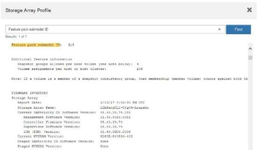
Step 3. Using the feature pack submodel ID, locate the corresponding Controller submodel ID for the starting configuration and find the Feature Code for the desired ending configuration within the table below. Then, copy that Feature Code to a text file.
| Starting configuration Ending configuration | Feature Code | |||||
| Controller Submodel ID | Base-board Ports | HIC Ports (if not SAS) | Controller Submodel ID | Base-board Ports | HIC Ports (if not SAS) | |
| DE2000H | ||||||
| 422 | FC FC, no | HIC, or not an optical HIC | 423 | iSCSI iSCI | no HIC, or not an optical HIC | B4DH |
| 423 | iSCSI iSCI | no HIC, or not an optical HIC | 422 | FC FC, no | HIC, or not an optical HIC | B4XC |
| Starting configuration Ending configuration | Feature Code | |||||
| Controller Submodel ID | Base-board Ports | HIC Ports (if not SAS) | Controller Submodel ID | Base-board Ports | HIC Ports (if not SAS) | |
| DE4000H | ||||||
| 424 | FC FC | 425 | iSCSI FC | B4XH | ||
| 424 | FC FC | 427 | iSCSI iSCI | B4E1 | ||
| 424 | FC FC | 426 | FC iSCSI | B4XK | ||
| 425 | iSCSI FC | 424 | FC FC B4XJ | |||
| 425 | iSCSI FC | 426 | FC iSCSI | B4XM | ||
| 425 | iSCSI FC | 427 | iSCSI iSCI | B4XP | ||
| 426 | FC iSCSI | 424 | FC FC B4 | XL | ||
| 426 | FC iSCSI | 425 | iSCSI FC | B4XN | ||
| 426 | FC iSCSI | 427 | iSCSI iSC | SI B4XR | ||
| 427 | iSCSI iSCSI | 424 | FC FC B4 | XG | ||
| 427 | iSCSI iSCSI | 425 | iSCSI FC | B4XQ | ||
| 427 | iSCSI iSCSI | 426 | FC iSCSI | B4XS | ||
| DE4000F | ||||||
| 428 | FC FC | 429 | iSCSI FC | B4DK | ||
| 428 | FC FC | 430 | FC iSCSI | B4XU | ||
| 428 | FC FC | 431 | iSCSI iSC | SI B4G7 | ||
| 429 | iSCSI FC | 428 | FC FC B4 | DL | ||
| 429 | iSCSI FC | 430 | FC iSCSI | B4XW | ||
| 429 | iSCSI FC | 431 | iSCSI iSCSI | B4XY | ||
| 430 | FC iSCSI | 428 | FC FC | B4XV | ||
| 430 | FC iSCSI | 429 | iSCSI FC | B4XX | ||
| 430 | FC iSCSI | 431 | iSCSI iSCSI | B4Y0 | ||
| 431 | iSCSI iSCSI | 428 | FC FC | B4XT | ||
| 431 | iSCSI iSCSI | 429 | iSCSI FC | B4XZ | ||
| 431 | iSCSI iSCSI | 430 | FC iSCSI | B4LZ | ||
| Starting configuration Ending configuration | Feature Code | |||||
| Controller Submodel ID | Base-board Ports | HIC Ports (if not SAS) | Controller Submodel ID | Base-board Ports | HIC Ports (if not SAS) | |
| DE6000H | ||||||
| 432 | FC FC | 433 | iSCSI iSCI B4JM | |||
| 433 | iSCSI iSCI | 432 | FC FC B4XD | |||
| DE6000F | ||||||
| 434 | FC FC | 435 | iSCSI iSCI | B4JK | ||
| 435 | iSCSI iSCI | 434 | FC FC B4XE | |||
Note: If your Controller submodel ID is not listed, contact DE Series Product Support Site.
Step 4. In System Manager, locate the Feature Enable Identifier.
a. Go to Settings → System.
b. Scroll down to Add-ons.
c. Under Change Feature Pack, locate the Feature Enable Identifier.
d. Copy and paste this 32-digit number to a text file.
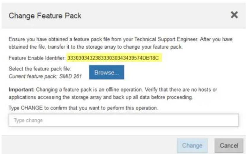
Step 5. Go to Lenovo Features on Demand, click on Storage Host Protocol Change, and enter the information required to obtain the feature pack.
- Feature Code
- Machine Type
- Chassis serial number
- Feature Enable Identifier (UID)
Step 6. Choose whether to receive the key file for the feature pack in an email or download it directly from the site.
Go to "Stop host I/O" on page 191.
Stop host I/O
You must stop all I/O operations from the host before converting the protocol of the host ports. You cannot access data on the storage array until you successfully complete the conversion.
Step 1. Ensure that no I/O operations are occurring between the storage array and all connected hosts. For example, you can perform these steps:
- Stop all processes that involve the LUNs mapped from the storage to the hosts.
- Ensure that no applications are writing data to any LUNs mapped from the storage to the hosts.
- Unmount all file systems associated with volumes on the array.
Note: The exact steps to stop host I/O operations depend on the host operating system and the configuration, which are beyond the scope of these instructions. If you are not sure how to stop host I/O operations in your environment, consider shutting down the host.
Attention: Possible data loss – If you continue this procedure while I/O operations are occurring, the host application might lose data because the storage array will not be accessible.
Step 2. If the storage array participates in a mirroring relationship, stop all host I/O operations on the secondary storage array.
Step 3. Wait for any data in cache memory to be written to the drives. The green Cache Active LED on the back of each controller is on when cached data needs to be written to the drives. You must wait for this LED to turn off.
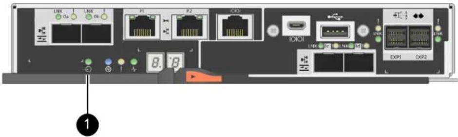
① Cache Active LED
Step 4. From the Home page of ThinkSystem System Manager, select View Operations in Progress.
Step 5. Wait for all operations to complete before continuing with the next step.
Go to "Change the feature pack" on page 192
Change the feature pack
You change the feature pack to convert the host protocol of the baseboard host ports and the host ports on the DE4000 16G FC or 10GbE iSCSI HIC.
Step 1. From ThinkSystem System Manager, select Settings → System.
Step 2. Under Add-ons, select Change Feature Pack.
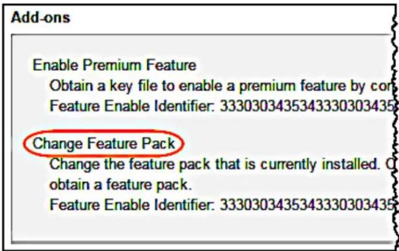
Step 3. Click Browse, and then select the feature pack you want to apply.
Step 4. Type CHANGE in the field.
Step 5. Click Change.
The feature pack migration begins. Both controllers automatically reboot twice to allow the new feature pack to take effect. The storage array returns to a responsive state after the reboot is complete.
Step 6. Confirm the host ports have the protocol you expect.
a. From ThinkSystem System Manager, select Hardware.
b. Click Show back of shelf.
c. Select the graphic for either Controller A or Controller B.
d. Select View settings from the context menu.
e. Select the Host Interfaces tab.
f. Click Show more settings.
g. Review the details shown for the baseboard ports and the HIC ports (labeled "slot 1"), and confirm that each type of port has the protocol you expect.
Go to "Complete host protocol conversion" on page 193.
Complete host protocol conversion
After converting the protocol of the host ports, you need to perform additional steps before you can use the new protocol. The steps you might need to complete depend on the starting and ending protocols of the baseboard host ports and the HIC ports.
Complete FC to iSCSI conversion
If you converted all host ports from FC to iSCSI, you must configure iSCSI networking.
Step 1. Configure the switches.You should configure the switches used to transport iSCSI traffic according to the vendor's recommendations for iSCSI. These recommendations might include both configuration directives as well as code updates.
Step 2. From ThinkSystem System Manager, select Hardware → Configure iSCSI ports.
Step 3. Select the port settings. You can set up your iSCSI network in many ways. Consult your network administrator for tips on selecting the best configuration for your environment.
Step 4. Update the host definitions in ThinkSystem System Manager.
Note: If you need instructions for add hosts or host clusters, refer to the online help for ThinkSystem System Manager.
a. Select Storage → Hosts.
b. Select the host to which the port will be associated, and click View/Edit Settings. The Host Settings dialog box appears.
c. Click the Host Ports tab.

d. Click Add, and use the Add Host Port dialog box to associate a new host port identifier to the host. The length of the host port identifier name is determined by the host interface technology. FC host port identifier names must have 16 characters. iSCSI host port identifier names have a maximum of 223 characters. The port must be unique. A port number that has already been configured is not allowed.
e. Click Delete, and use the Delete Host Port dialog box to remove (unassociate) a host port identifier. The Delete option does not physically remove the host port. This option removes the association between the host port and the host. Unless you remove the host bus adapter or the iSCSI initiator, the host port is still recognized by the controller.
f. Click Save to apply your changes to the host port identifier settings.
g. Repeat these steps to add and remove any additional host port identifiers.
Step 5. Reboot the host or perform a rescan so that the host properly discovers the LUNs.
Step 6. Remount volumes or start using block volume.
Complete iSCSI to FC conversion
If you converted all host ports from iSCSI to FC, you must configure FC networking.
Step 1. Install the HBA utility and determine initiator WWPNs.
Step 2. Zone the switches.
Zoning the switches enables the hosts to connect to the storage and limits the number of paths. You zone the switches using the management interface of the switches.
Step 3. Update the host definitions in ThinkSystem System Manager.
a. Select Storage → Hosts.
b. Select the host to which the port will be associated, and click View/Edit Settings. The Host Settings dialog box appears.
c. Click the Host Ports tab.
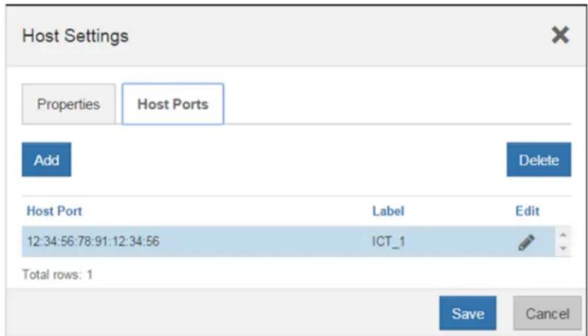
d. Click Add, and use the Add Host Port dialog box to associate a new host port identifier to the host. The length of the host port identifier name is determined by the host interface technology. FC host port identifier names must have 16 characters. iSCSI host port identifier names have a maximum of 223 characters. The port must be unique. A port number that has already been configured is not allowed.
e. Click Delete, and use the Delete Host Port dialog box to remove (unassociate) a host port identifier. The Delete option does not physically remove the host port. This option removes the
association between the host port and the host. Unless you remove the host bus adapter or the iSCSI initiator, the host port is still recognized by the controller.
f. Click Save to apply your changes to the host port identifier settings.
g. Repeat these steps to add and remove any additional host port identifiers.
Step 4. Reboot the host or perform a rescan so that the host properly discovers mapped storage.
Step 5. Remount volumes or start using block volume.
Complete FC to FC/iSCSI conversion
If you previously had all FC host ports and you converted some of them to iSCSI, you might need to modify your existing configuration to support iSCSI.
You can use either of the following options to use the new iSCSI ports. The exact steps depend on your current and planned network topologies.
Option 1 assumes that you want to attach new iSCSI hosts to the array. Option 2 assumes that you want to convert the hosts connected to the converted ports from FC to iSCSI.
Option 1: Move FC hosts and add new iSCSI hosts
Step 1. Move any FC hosts from the new iSCSI ports to the ports that remain FC.
Step 2. If you are not already using dual-protocol SFPs, remove any FC SFPs.
Step 3. Attach new iSCSI hosts to these ports, either directly or by using a switch.
Step 4. Configure iSCSI networking for the new hosts and ports.
Option 2: Convert FC hosts to iSCSI
Step 1. Shut down the FC hosts connected to the converted ports.
Step 2. Provide an iSCSI topology for the converted ports. For example, convert any switches from FC to iSCSI.
Step 3. If you are not already using dual-protocol SFPs, remove the FC SFPs from the converted ports, and replace them with iSCSI SFPs or dual-protocol SFPs.
Step 4. Attach cables to the SFPs in the converted ports, and confirm they are connected to the correct iSCSI switch or host.
Step 5. Power on the hosts.
Step 6. Configure the iSCSI hosts.
Step 7. Edit the host partition to add the iSCSI host port IDs and remove the FC host port IDs.
Step 8. After the iSCSI hosts reboot, use the applicable procedures on the hosts to register the volumes and to make them available to your operating system.
- Depending on your operating system, two utilities are included with the storage management software (hot_add and SMdevices). These utilities help register the volumes with the hosts and also show the applicable device names for the volumes.
- You might need to use specific tools and options that are provided with your operating system to make the volumes available (that is, assign drive letters, create mount points, and so on). Refer to your host operating system documentation for details.
Complete iSCSI to FC/iSCSI conversion
If you previously had all iSCSI host ports and you converted some of them to FC, you might need to modify your existing configuration to support FC.
You can use either of the following options to use the new FC ports. The exact steps depend on your current and planned network topologies.
Option 1 assumes that you want to attach new FC hosts to the array. Option 2 assumes that you want to convert the hosts connected to the converted ports from iSCSI to FC.
Option 1: Move iSCSI hosts and add new FC hosts
Step 1. Move any iSCSI hosts from the new FC ports to the ports that remain iSCSI.
Step 2. If you are not already using dual-protocol SFPs, remove any FC SFPs.
Step 3. Attach new FC hosts to these ports, either directly or by using a switch.
Step 4. Configure FC networking for the new hosts and ports.
Option 2: Convert iSCSI hosts to FC
Step 1. Shut down the iSCSI hosts connected to the converted ports.
Step 2. Provide an FC topology for the converted ports. For example, convert any switches from iSCSI to FC.
Step 3. If you are not already using dual-protocol SFPs, remove the iSCSI SFPs from the converted ports, and replace them with FC SFPs or dual-protocol SFPs.
Step 4. Attach cables to the SFPs in the converted ports, and confirm they are connected to the correct FC switch or host.
Step 5. Power on the hosts.
Step 6. Configure the FC hosts.
Step 7. Edit the host partition to add the FC host port IDs and remove the iSCSI host port IDs.
Step 8. After the new FC hosts reboot, use the applicable procedures on the hosts to register the volumes and to make them available to your operating system.
- Depending on your operating system, two utilities are included with the storage management software (hot_add and SMdevices). These utilities help register the volumes with the hosts and also show the applicable device names for the volumes.
- You might need to use specific tools and options that are provided with your operating system to make the volumes available (that is, assign drive letters, create mount points, and so on). Refer to your host operating system documentation for details.
Complete FC/iSCSI to FC conversion
If you previously had a combination of FC host ports and iSCSI host ports and you converted all ports to FC, you might need to modify your existing configuration to use the new FC ports.
You can use either of the following options to use the new FC ports. The exact steps depend on your current and planned network topologies.
Option 1 assumes that you want to attach new FC hosts to the array. Option 2 assumes that you want to convert the hosts connected to ports 1 and 2 from iSCSI to FC.
Option 1: Remove iSCSI hosts and add FC hosts
Step 1. If you are not already using dual-protocol SFPs, remove any iSCSI SFPs, and replace them with FC SFPs or dual-protocol SFPs.
Step 2. If you are not already using dual-protocol SFPs, remove any FC SFPs.
Step 3. Attach new FC hosts to these ports, either directly or by using a switch
Step 4. Configure FC networking for the new hosts and ports.
Option 2: Convert iSCSI hosts to FC
Step 1. Shut down the iSCSI hosts connected to the ports you converted.
Step 2. Provide an FC topology for these ports. For example, convert any switches connected to those hosts from iSCSI to FC.
Step 3. If you are not already using dual-protocol SFPs, remove the iSCSI SFPs from the ports, and replace them with FC SFPs or dual-protocol SFPs.
Step 4. Attach cables to the SFPs, and confirm they are connected to the correct FC switch or host.
Step 5. Power on the hosts.
Step 6. Configure the FC hosts.
Step 7. Edit the host partition to add the FC host port IDs and remove the iSCSI host port IDs.
Step 8. After the new FC hosts reboot, use the applicable procedures on the hosts to register the volumes and to make them available to your operating system.
- Depending on your operating system, two utilities are included with the storage management software (hot_add and SMdevices). These utilities help register the volumes with the hosts and also show the applicable device names for the volumes.
- You might need to use specific tools and options that are provided with your operating system to make the volumes available (that is, assign drive letters, create mount points, and so on). Refer to your host operating system documentation for details.
Complete FC/iSCSI to FC conversion
If you previously had a combination of FC host ports and iSCSI host ports and you converted all ports to iSCSI, you might need to modify your existing configuration to use the new iSCSI ports.
You can use either of the following options to use the new iSCSI ports. The exact steps depend on your current and planned network topologies.
Option 1 assumes that you want to attach new iSCSI hosts to the array. Option 2 assumes that you want to convert the hosts from FC to iSCSI.
Option 1: Remove FC hosts and add iSCSI hosts
Step 1. If you are not already using dual-protocol SFPs, remove any FC SFPs, and replace them with iSCSI SFPs or dual-protocol SFPs.
Step 2. Attach new iSCSI hosts to these ports, either directly or by using a switch.
Step 3. Configure iSCSI networking for the new hosts and ports.
Option 2: Convert FC hosts to iSCSI
Step 1. Shut down the FC hosts connected to the ports you converted.
Step 2. Provide an iSCSI topology for these ports. For example, convert any switches connected to those hosts from FC to iSCSI.
Step 3. If you are not already using dual-protocol SFPs, remove the FC SFPs from the ports, and replace them with iSCSI SFPs or dual-protocol SFPs.
Step 4. Attach cables to the SFPs, and confirm they are connected to the correct iSCSI switch or host.
Step 5. Power on the hosts.
Step 6. Configure the iSCSI hosts.
Step 7. Edit the host partition to add the iSCSI host port IDs and remove the FC host port IDs.
Step 8. After the new iSCSI hosts reboot, use the applicable procedures on the hosts to register the volumes and to make them available to your operating system.
- Depending on your operating system, two utilities are included with the storage management software (hot_add and SMdevices). These utilities help register the volumes with the hosts and also show the applicable device names for the volumes.
- You might need to use specific tools and options that are provided with your operating system to make the volumes available (that is, assign drive letters, create mount points, and so on). Refer to your host operating system documentation for details.
Chapter 4. System upgrade
This chapter describes how to upgrade your controller and ThinkSystem SAN OS software.
What's New in DE Series software version 11.50.2
This version includes only minor enhancements and fixes.
Additional information
This topic provides additional information about your DE Series storage product.
How to access the End-User License Agreement
The End-User License Agreement is displayed when the SAN Manager and Storage Manager are installed on a client machine. Read and accept the license agreement terms and click Next to proceed with the installation.

Figure 46. End-User License Agreement
To view the EULA after you have completed the software installation, you can click Help → Legal Information → End User License Agreement in Acrobat PDF format.
Legal Information
To view the Lenovo disclosures about Linux Open Source licensing, you can click Help → Legal Information. Then the following screen will be displayed:
Click Third-party Licenses to view the Open Source Notices files on the DE Series Product Support Site Lenovo DE Series support page, or click Open Source Information to view the Lenovo Written Offer in Acrobat PDF format.
Multi-Path setup
Multipathing enables you to configure multiple I/O paths between server nodes and storage arrays into a single device. These I/O paths are physical SAN connections that can include separate cables, switches, and controllers.
The following instructions are provided for the administrator of the DE Series storage array to set up multi-path for Linux, Windows, and VMWare.
Linux general multipathing
Use the host mapping "Linux DM-MP (Kernel 3.10 or later)" for all Linux OS.
- For RHEL 7.1 - 7.6, SLES 11 SP4, and SLES 12 SP1 - SP4, do the following:
- Modify the multipath.conf settings. Here are the recommended settings:
devices {
device {
vendor "LENOVO"
product "DE_Series"
product_blacklist "Universal Xport"
path_grouping_policy "group_by_prio"
path_checker "rdac"
features "2 pg_init_retries 50"
hardware_handler "1 rdac"
prio "rdac"
failback immediate
rr_weight "uniform"
no_path_retry 30
retain_attached_hw_handler yes
detect_prio yes
}
- Restart the multipathd service.
- If SAN boot, rebuild initramfs after updating the multipath.conf file.
- For RHEL 6.7 - 6.9, modify the above multipath.conf settings and then do the following:
- Run the following command to add "rdloaddriver=scsi_dh_alua" to the bootloader (in menu.lst): grubby --update-kernel=ALL --args=rdloaddriver=scsi_dh_alua
- If SAN boot, rebuild initramfs to include scsi_dh_alua module: dracut -f --add-drivers scsi_dh_alua /boot/initramfs-\(uname -r).img \(uname -r)
- Restart the host.
Windows
- If MPIO is not installed, add the MPIO feature to Windows from the Server Manager and then restart the system.
- If SAN booting, install with single path, then install ThinkSystem Storage Manager and restart before presenting the rest of the paths to the host.
- If not SAN booting, install ThinkSystem Storage Manager before presenting LUNs to the host.
VMware
After the installation, manually create claim rule with the following command. Then restart the client machine: esxcli storage nmp satp rule add -s VMW_SATP_ALUA -V LENOVO -M DE_Series -c tpgs_on -P VMW_PSP_RR -e "Lenovo DE-Series arrays with ALUA support"
For iSCSI SANboot, ensure any vmkernel that participates in SANboot has a MAC address that matches the physical adapter. The default adapter created during the installation will match by default.
Use the following command to create additional vmkernel to specify the MAC address: esxcli network ip interface add -i [vmkernel name] -M "[MAC address]" -p "[Portgroup name]" -m [MTUSIZE]
Upgrade ThinkSystem SAN OS software
Overview and upgrade considerations
Learn what you need to know before upgrading your storage array's ThinkSystem SAN OS controller software and firmware and its drive firmware.
Considerations for upgrading software and firmware for multiple controllers
Before you use ThinkSystem SAN Manager to upgrade multiple storage arrays, review the key considerations as part of your planning.
Current versions
You can view the current ThinkSystem OS software versions from the Manage page of SAN Manager for each discovered storage array. The version is shown in the ThinkSystem OS Software column. The controller firmware and NVSRAM information is available in a pop-up dialog box when you click on the ThinkSystem OS version in each row.
Other components requiring upgrade
As part of the upgrade process, you might also need to upgrade the host's multipath/failover driver or the HBA driver so that the host can interact with the controllers correctly.
For compatibility information, refer to the Lenovo Interoperability Matrix. Also, see the procedures in the Express Guides for your operating system.
Dual controllers
If a storage array contains two controllers and you have a multipath driver installed, the storage array can continue to process I/O while the upgrade occurs. During the upgrade, the following process occurs:
- Controller A fails over all its LUNs to controller B.
- Upgrade occurs on controller A.
- Controller A takes back its LUNs and all of controller B's LUNs.
- Upgrade occurs on controller B.
After the upgrade completes, you might need to manually redistribute volumes between the controllers to ensure volumes return to the correct owning controller.
Immediate or staged upgrade
You can activate the upgrade immediately or stage it for a later time. You might choose to activate later for these reasons:
- Time of day – Activating the software can take a long time, so you might want to wait until I/O loads are lighter. The controllers reboot and fail over during activation so performance might be lower than usual until the upgrade completes.
- Type of package – You might want to test the new software and firmware on one storage array before upgrading the files on other storage arrays.
To activate staged software, go to Upgrade Center → Activate Staged OS Software.
Health check
A health check runs as part of the upgrade process, but you can also run a health check separately before you begin (go to Upgrade Center → Pre-Upgrade Health Check).
The health check assesses all storage system components to make sure that the upgrade can proceed. The following conditions might prevent the upgrade:
- Failed assigned drives
- Hot spares in use
• Incomplete volume groups
• Exclusive operations running - Missing volumes
- Controller in Non-optimal status
- Excess number of event log events
- Configuration database validation failure
- Drives with old versions of DACstore
Considerations for upgrading drive firmware
Take into account some key considerations before upgrading your drive firmware.
Drive compatibility
Each drive firmware file contains information about the drive type on which the firmware runs. You can download the specified firmware file only to a compatible drive. System Manager automatically checks compatibility during the upgrade process.
Drive upgrade methods
There are two types of drive firmware upgrade methods: online and offline.
| Online upgrade Offline upgrade | |
| During an online upgrade, drives are upgraded sequentially, one at a time. The storage array continues processing I/O while the upgrade occurs. You do not have to stop I/O. If a drive can do an online upgrade, the online method is used automatically.Drives that can do an online upgrade include the following:Drives in an Optimal poolDrives in an Optimal redundant volume group (RAID 1, RAID 5, and RAID 6)Unassigned drivesStandby hot spare drivesDoing an online drive firmware upgrade can take several hours exposing the storage array to potential volume failures. Volume failure could occur in these cases:In a RAID 1 or RAID 5 volume group, one drive fails while a different drive in the volume group is being upgraded.In a RAID 6 pool or volume group, two drives fail while a different drive in the pool or volume group is being upgraded. | During an offline upgrade, all drives of the same drive type are upgraded at the same time. This method requires stopping I/O activity to the volumes associated with the selected drives. Because multiple drives can be upgraded concurrently (in parallel), the overall downtime is significantly reduced. If a drive can do only an offline upgrade, the offline method is used automatically.The following drives MUST use the offline method:Drives in a non-redundant volume group (RAID 0)Drives in a non-optimal pool or volume groupDrives in SSD cache |
Workflows for upgrading software and firmware
The following workflows provide an overview for upgrading software and firmware for multiple controllers, and drive firmware.
Upgrade software and firmware for multiple controllers workflow
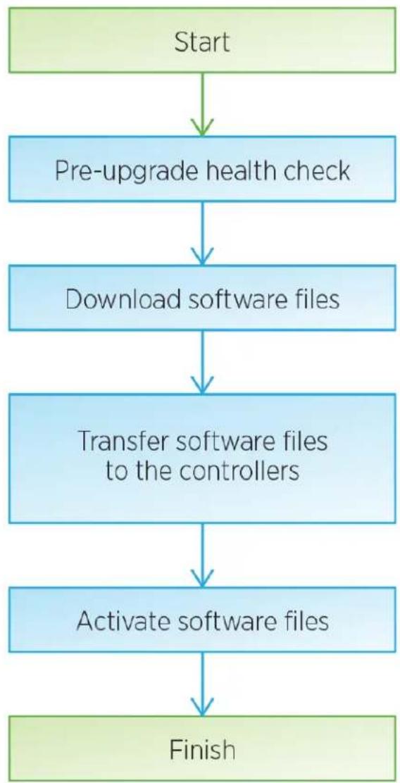
flowchart
graph TD
    A["Start"] --> B["Pre-upgrade health check"]
    B --> C["Download software files"]
    C --> D["Transfer software files to the controllers"]
    D --> E["Activate software files"]
    E --> F["Finish"]
Upgrade drive firmware workflow
| Start |
| Download drive firmware files. |
| Begin drive firmware upgrade. |
| Finish |
Upgrade software and firmware for multiple controllers
You can use ThinkSystem SAN Manager to upgrade the ThinkSystem OS software on multiple storage arrays of the same type to a newer version.
Perform pre-upgrade health check
A health check runs as part of the upgrade process, but you also can run a health check separately before you begin. The health check assesses components of the storage array to make sure that the upgrade can proceed.
Step 1. From the main view, select Manage, and then select Upgrade Center → Pre-Upgrade Health Check.
The Pre-Upgrade Health Check dialog box opens and lists all the discovered storage systems.
Step 2. If needed, filter or sort the storage systems in the list, so you can view all systems that are not currently in the Optimal state.
Step 3. Select the check boxes for the storage systems that you want to run through the health check.
Step 4. Click Start.
The progress is shown in the dialog box while the health check is performed.
Step 5. When the health check completes, you can click on the ellipses to the right of each row to view more information and perform other tasks.
Go to "Download software files from support site" on page 205
Download software files from support site
You download the ThinkSystem OS software package from the Lenovo Support Site to your management host system.
- The latest ThinkSystem OS files are available on the host system where the ThinkSystem Web Services Proxy and ThinkSystem SAN Manager are running.
-
You know whether you want to activate your software upgrade now or later. You might choose to activate later for these reasons:
-
Time of day – Activating the software can take a long time, so you might want to wait until I/O loads are lighter. The controllers fail over during activation, so performance might be lower than usual until the upgrade completes.
- Type of package – You might want to test the new OS software on one storage array before you upgrade the files on other storage arrays.
Important: Risk of data loss or risk of damage to the storage array - Do not make changes to the storage array while the upgrade is occurring. Maintain power to the storage array.
Step 1. If your storage array contains only one controller or you do not have a multipath driver installed, stop I/O activity to the storage array to prevent application errors. If your storage array has two controllers and you have a multipath driver installed, you do not need to stop I/O activity.
Step 2. From the main view, select Manage, and then select one or more storage arrays that you want to upgrade.
Step 3. Select Upgrade Center → Upgrade ThinkSystem OS Software.
The Upgrade ThinkSystem OS software page appears.
Step 4. Download the latest ThinkSystem OS software package from the Support site to your local machine.
a. Click Add new file to software repository.
b. Click the link for finding the latest ThinkSystem OS Downloads.
c. Click the Download Latest Release link.
d. Follow the remaining instructions to download the ThinkSystem OS file and the NVSRAM file to your local machine.
Note: Digitally signed firmware is required in version 8.42 and above. If you attempt to download unsigned firmware, an error is displayed and the download is aborted.
Go to "Transfer software files to the controllers" on page 206.
Transfer software files to the controllers
You load the ThinkSystem OS software file and the NVSRAM file into the repository (an area of the Web Services Proxy server where files are stored).
Important: Risk of data loss or risk of damage to the storage array - Do not make changes to the storage array while the upgrade is occurring. Maintain power to the storage array.
Step 1. From the main view, select Manage, and then select one or more storage arrays that you want to upgrade.
Step 2. Select Upgrade Center → Upgrade ThinkSystem OS Software.
The Upgrade ThinkSystem OS software page appears.
Step 3. Download the latest ThinkSystem OS software package from the Support site to your local machine.
a. Click Add new file to software repository.
b. Click the link for finding the latest ThinkSystem OS Downloads.
c. Click the Download Latest Release link.
d. Follow the remaining instructions to download the ThinkSystem OS file and the NVSRAM file to your local machine.
Note: Digitally signed firmware is required in version 8.42 and above. If you attempt to download unsigned firmware, an error is displayed and the download is aborted.
Step 4. Select the OS software file and the NVSRAM file that you want to use to upgrade the controllers:
a. From the Select a ThinkSystem OS software file drop-down, select the OS file that you downloaded to your local machine.
If there are multiple files available, the files are sorted from newest date to oldest date.
Note: The software repository lists all software files associated with the Web Services Proxy. If you do not see the file that you want to use, you can click the link, Add new file to software repository, to browse to the location where the OS file that you want to add resides.
b. From the Select an NVSRAM file drop-down, select the controller file that you want to use.
If there are multiple files, the files are sorted from newest date to oldest date.
Step 5. In the Compatible Storage Array table, review the storage arrays that are compatible with the OS software file that you selected, and then select the arrays you want to upgrade.
- The storage arrays that you selected in the Manage view and that are compatible with the selected firmware file are selected by default in the Compatible Storage Array table.
- The storage arrays that cannot be updated with the selected firmware file are not selectable in the Compatible Storage Array table as indicated by the status Incompatible.
Step 6. (Optional) To transfer the software file to the storage arrays without activating them, select the Transfer the OS software to the storage arrays, mark it as staged, and activate at a later time check box.
Step 7. Click Start.
Step 8. Depending on whether you chose to activate now or later, do one of the following:
Type TRANSFER to confirm that you want to transfer the proposed OS software versions on the arrays you selected to upgrade, and then click Transfer.
To activate the transferred software, select Upgrade Center → Activate Staged OS Software.
Type UPGRADE to confirm that you want to transfer and activate the proposed OS software versions on the arrays you selected to upgrade, and then click Upgrade.
The system transfers the software file to each storage array you selected to upgrade and then activates that file by initiating a reboot.
The following actions occur during the upgrade operation:
- A pre-upgrade health check runs as part of the upgrade process. The pre-upgrade health check assesses all storage array components to make sure that the upgrade can proceed.
- If any health check fails for a storage array, the upgrade stops. You can click the ellipsis (...) and select Save Log to review the errors. You can also choose to override the health check error and then click Continue to proceed with the upgrade.
- You can cancel the upgrade operation after the pre-upgrade health check.
Step 9. (Optional) Once the upgrade has completed, you can see a list of what was upgraded for a specific storage array by clicking the ellipsis (...) and then selecting Save Log.
The file is saved in the Downloads folder for your browser with the name upgrade_log-
If you have already activated your software files, your controller software upgrade is complete; otherwise go to "Activate staged software files (optional)" on page 207.
Activate staged software files (optional)
You can choose to activate the software file immediately or wait until a more convenient time. This procedure assumes you chose to activate the software file at a later time.
- Time of day – Activating the software can take a long time, so you might want to wait until I/O loads are lighter. The controllers reboot and fail over during activation so performance might be lower than usual until the upgrade completes.
- Type of package – You might want to test the new software and firmware on one storage array before upgrading the files on other storage arrays.
Attention: You cannot stop the activation process after it starts.
Step 1. From the main view, select Manage. If necessary, click the Status column to sort, at the top of the page, all storage arrays with a status of "OS Upgrade (awaiting activation)."
Step 2. Select one or more storage arrays that you want to activate software for, and then select Upgrade Center → Activate Staged OS Software.
The following actions occur during the upgrade operation:
- A pre-upgrade health check runs as part of the upgrade process. The pre-upgrade health check assesses all storage array components to make sure that the upgrade can proceed.
- If any health check fails for a storage array, the upgrade stops. You can click the ellipsis (...) and select Save Log to review the errors. You can also choose to override the health check error and then click Continue to proceed with the upgrade.
- You can cancel the upgrade operation after the pre-upgrade health check.
On successful completion of the pre-upgrade health check, activation occurs. The time it takes to activate depends on your storage array configuration and the components that you are activating.
Step 3. (Optional) After the upgrade is complete, you can see a list of what was upgraded for a specific storage array by clicking the ellipsis (...) and then selecting Save Log.
The file is saved in the Downloads folder for your browser with the name activate_log-
Your controller software upgrade is complete. You can resume normal operations.
Upgrade drive firmware
You upgrade your drives' firmware to make sure you have all the latest features and bug fixes.
Download drive firmware files from support site
You download the drive firmware files from the Lenovo Support Web site to your management client.
Step 1. Enter a valid DE Series controller Machine Type in the Find Your Product field. For example, 7Y70, 7Y71, 7Y74, 7Y75, 7Y76, 7Y77, 7Y78, 7Y79 or 7Y80.
Step 2. Select Driver & Software.
Step 3. Select Software and Utilities.
Step 4. Select Hard Disk Drive Firmware Update.
Step 5. Follow the remaining instructions.
Go to "Begin drive firmware upgrade" on page 208.
Begin drive firmware upgrade
You upgrade your drives' firmware to make sure you have all the latest features and bug fixes.
Before you begin
- You have backed up your data using disk-to-disk backup, volume copy (to a volume group not affected by the planned firmware upgrade), or a remote mirror.
- The storage array has an Optimal status.
- All drives have an Optimal status.
- No configuration changes are running on the storage array.
- If the drives are capable of only an offline upgrade, I/O activity to all volumes associated with the drives is stopped.
Step 1. Under Drive Firmware upgrade, click Begin Upgrade.
A dialog box appears, which lists the drive firmware files currently in use.
Step 2. Extract (unzip) the files you downloaded from the Support site.
Step 3. Click Browse, and select the new drive firmware files that you downloaded from the Support site.
Drive firmware files have a filename similar to D_ST1800MM0068_30602828_NE01_5600_001 (depending on the vendor) with the extension of .dlp.
You can select up to four drive firmware files, one at a time. If more than one drive firmware file is compatible with the same drive, you get a file conflict error. Decide which drive firmware file you want to use for the upgrade and remove the other one.
Step 4. Click Next.The Select Drives dialog box appears, which lists the drives that you can upgrade with the selected files.
Only drives that are compatible appear.
The selected firmware for the drive appears in the Proposed Firmware information area. If you must change the firmware, click Back to return to the previous dialog.
Step 5. Select the type of upgrade you want to perform:
- Online (default)- Shows the drives that can support a firmware download while the storage array is processing I/O. You do not have to stop I/O to the associated volumes using these drives when you select this upgrade method. These drives are upgraded one at a time while the storage array is processing I/O to those drives.
- Offline (parallel) - Shows the drives that can support a firmware download only while all I/O activity is stopped on any volumes that use the drives. You must stop all I/O activity on any volumes that use the drives you are upgrading when you select this upgrade method. Drives that do not have redundancy must be processed as an offline operation. This requirement includes any drive associated with SSD cache, a RAID 0 volume group, or any pool or volume group that is degraded.
Step 6. In the first column of the table, select the drive or drives you want to upgrade.
Step 7. Click Start, and confirm that you want to perform the operation.
If you need to stop the upgrade, click Stop. Any firmware downloads currently in progress complete. Any firmware downloads that have not started are canceled.
Attention: Stopping the drive firmware upgrade might result in data loss or unavailable drives.
Step 8. (Optional) To see a list of what was upgraded, click Save Log.
The file is saved in the Downloads folder for your browser with the name latest-upgrade-log-timestamp.txt.
Step 9. If any of the following errors occur during the upgrade procedure, take the appropriate recommended action.
| If you encounter this firmware download error... | Then do the following... |
| Failed assigned drives | One reason for the failure might be that the drive does not have the appropriate signature. Make sure that the affected drive is an authorized drive. Contact technical support for more information.When replacing a drive, make sure that the replacement drive has a capacity equal to or greater than the failed drive you are replacing.You can replace the failed drive while the storage array is receiving I/O. |
| Check storage array | Make sure that an IP address has been assigned to each controller.Make sure that all cables connected to the controller are not damaged.Make sure that all cables are tightly connected. |
| Integrated hot spare drives | This error condition must be corrected before you can upgrade the firmware. Launch System Manager and use the Recovery Guru to resolve the problem. |
| Incomplete volume groups | If one or more volume groups or disk pools are incomplete, you must correct this error condition before you can upgrade the firmware. Launch System Manager and use the Recovery Guru to resolve the problem. |
| Exclusive operations (other than background media/parity scan) currently running on any volume groups | If one or more exclusive operations are in progress, the operations must complete before the firmware can be upgraded. Use System Manager to monitor the progress of the operations. |
| Missing volumes You must correct the missing volume conditionbefore the firmware can be upgraded. Launch System Manager and use the Recovery Guru to resolve the problem. | |
| Either controller in a state other than Optimal One of the storage array controllers needs attention. This condition must be corrected before the firmware can be upgraded. Launch System Manager and use the Recovery Guru to resolve the problem. | |
| Mismatched Storage Partition information between Controller Object Graphs | An error occurred while validating the data on the controllers. Contact technical support to resolve this issue. |
| SPM Verify Database Controller check fails | A storage partitions mapping database error occurred on a controller. Contact technical support to resolve this issue. |
| Configuration Database Validation (If supported by the storage array's controller version) | A configuration database error occurred on a controller. Contact technical support to resolve this issue. |
| MEL Related Checks Contact technical support to resolve this issue. | |
| More than 10 DDE Informational or Critical MEL events were reported in the last 7 days | Contact technical support to resolve this issue. |
| More than 2 Page 2C Critical MEL Events were reported in the last 7 days | Contact technical support to resolve this issue. |
| More than 2 Degraded Drive Channel Critical MEL events were reported in the last 7 days | Contact technical support to resolve this issue. |
| More than 4 critical MEL entries in the last 7 days | Contact technical support to resolve this issue. |
Your drive firmware upgrade is complete. You can resume normal operations.
Chapter 5. System monitoring
The chapter contains a list and description of the LED indicators for DE series storage array components, as well as a critical events reference that can be helpful in diagnosing issues and resolving problems.
Understanding the controller LEDs and displays
You can monitor the state of the hardware by using the LEDs and displays on the hardware and the Recovery Guru in System Manager. You can track events related to the operation of your storage array through the event log.
For 2U models, you can find LEDs on the following components:
• DE2000/DE4000/DE6000 controllers
- Operator display panel
- I/O modules (IOMs)
- Drives
• Power-fan canisters
For 4U models, you can find LEDs on the following components:
- Operator display panel
- I/O modules (IOMs)
- Drives
- Drive drawer
- Fan canisters
- Power canisters
• DE4000H/DE6000H controllers
In addition to LEDs, each controller has a seven-segment display, which indicates the operational status of the controller.
LEDs on the rear of controllers
The rear of the DE2000/DE4000/DE6000 controller includes LEDs that indicate when the controller is active, when the controller needs attention, when there is Ethernet activity, and so on.
The following examples show the LEDs on each of the available DE2000/DE4000/DE6000 controllers with host interface cards (HICs).

Figure 47. DE2000 controller with dual-port HIC

Figure 48. DE4000 controller with quad-port HIC

Figure 49. DE6000 controller with quad-port HIC
| 1 Cache Active | 2 Locate |
| 3 Attention Activity | |
| 5 Seven-segment display HIC Host Port Link Status | |
| 7 HIC Host Port Attention | 8 SAS Expansion Port Link Status |
| 9 SAS Expansion Port Attention | 10 Baseboard Host Port Link Status |
| 11 Baseboard Host Port Attention | 12 Ethernet Status |
| 13 Ethernet Activity |
The following table describes the controller LEDs and their operational statuses:
| LED | Status indicator | Description |
| Cache Active Green | The cache contains data not yet written to disk. | |
| Off Either the cache is inactive or all data from the cache has been preserved in non-volatile memory. | ||
| Locate Blue There is an active request to physically locate the controller shelf. | ||
| Attention Amber The controller is faulty and requires operator attention, and the faulty component is serviceable. | ||
| Activity Blinking green The controller is active. | ||
| Ethernet Activity (right) Green The link between the Management port and the device to which it is connected (such as an Ethernet switch) is up. | ||
| Blinking green There is Ethernet activity. | ||
| Ethernet Link State (left) Green | Link is established. | |
| Off | No link is established. | |
| SAS expansion Port Link Green | Link is established. | |
| Off | No link is established. | |
| SAS expansion Port Link Fault | Amber | Port is degraded (one or more Phys in the port is down). |
| Off Port is optimal (all Phys in the port are up or all Phys in the port are down since the LED is off if no cables are attached). | ||
| Host Port Link Status (SFP host port, FC or iSCSI) | Green The link is up (Fibre Channel).If the LED is solid, the link is up, but there is no activity (iSCSI).If the LED is flashing, the link is up and there is activity (iSCSI).If the LED is off, the link is down. | |
| Host Port Attention (SFP host port, FC or iSCSI) | Amber The port requires operator attention. | |
LEDs on the operator display panel
Each controller shelf or drive shelf has LEDs located on the operator display panel (ODP). The ODP is visible through the left end cap of a controller shelf or drive shelf.
LEDs on the operator display panel of 2U models
The following example shows the LEDs on the ODP of the DE4000H (12 drives) controller shelf. The LEDs on ODP also apply to DE2000H (12 or 24 drives), DE4000H (24 drives), DE4000F, DE6000H (24 drives), and DE6000F controller shelves. The LEDs on ODP also apply to DE120S and DE240S drive shelves.

Figure 50. LEDs on the operator display panel
| Components Status Description | ||
| 1 Power LED | Solid green One or m | ore power supplies are delivering power to the shelf. |
| Off No power supply | is delivering power to the shelf. | |
| 2 Attention LED (front) | Solid amber | There is an error with the function of one or more of the following: shelf, drives, IOMs, power supplies, or fans. |
| Off The system is operating normally. | ||
| 3 Location LED (front) Solid | blue or blinking blue | The shelf location LED is manually activated to help locating the shelf.Note:The location LED turns off automatically after 30 minutes. |
| Off The location LED | is not activated. | |
| 4 Shelf ID digital display Num | mber displayed Display | the digital shelf ID. |
LEDs on the operator display panel of 4U models
The following example shows the LEDs on the ODP for the DE4000H and DE6000H controller shelves. The LEDs on ODP also apply to DE600S drive shelf.
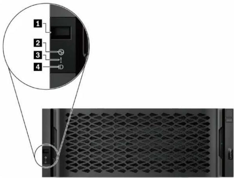
Figure 51. LEDs on the operator display panel
| Components Status | Description | |
| 1 Shelf ID digital display | Number displayed Display the digital shelf ID. | |
| 2 Power LED | Solid green One or more power supplies are delivering power to the shelf. | |
| Off No power supply is delivering power to the shelf. | ||
| 3 Attention LED (front) | Solid amber | There is an error with the function of one or more of the following: shelf, drives, IOMs, power supplies, or fans. |
| Off The system is operating normally. | ||
| 4 Location LED (front) Solid | blue or blinking blue | The shelf location LED is manually activated to help locating the shelf.Note:The location LED turns off automatically after 30 minutes. |
| Off | The location LED is not activated. | |
Setting the shelf ID with the ODP push button
You can set or change the shelf ID for a controller shelf or a drive shelf by using the ODP push button.
Before you begin
Each controller shelf or drive shelf has LEDs located on the operator display panel (ODP). You might need to remove the left end cap to see the ODP push button. The controller shelf or drive shelf must be powered on before you begin this task.
The following figure shows the ODP push button on controller shelf and drive shelf with 12 drives.

natural_image
Front view of a server rack with multiple drive bays and a control panel (no visible text or symbols)Figure 52. ODP push button on controller shelf and drive shelf with 12 drives
The following figure shows the ODP push button on controller shelf and drive shelf with 24 drives.

natural_image
Front view of a server rack with ventilation slots and a close-up of the internal device (no text or symbols visible)Figure 53. ODP push button on controller shelf and drive shelf with 24 drives
| 1 | ODP push button |
The following figure shows the ODP push button on controller shelf and drive shelf with 60 drives.

Figure 54. ODP push button on controller shelf and drive shelf with 60 drives
| 1 | ODP push button |
Step 1. Press and hold the push button until the first number on the seven-segment display starts to blink. It might take up to three seconds for the number to blink. If the number does not blink in this time, release the button and press it again. Make sure to press the button all the way in.
Step 2. Change the first number of the shelf ID by repeatedly pressing the push button to advance the number until you reach the desired number from 0 to 9. The first number continues to blink.
Step 3. Press and hold the button until the second number on the digital display starts to blink. It might take up to three seconds for the second number to blink. The first number on the seven-segment display stops blinking.
Step 4. Change the second number of the shelf ID by repeatedly pressing the button to advance the number until you reach the desired number from 0 to 9. The second number continues to blink.
Step 5. Lock in the desired number, and exit the programming mode by pressing and holding the button until the second number stops blinking. It might take up to three seconds for the second number to stop blinking.
LEDs on the drives
The drives that are installed in a controller shelf or drive shelf include an Activity LED and an Attention LED.
The following figure shows the LEDs on the 2.5-inch drives.

natural_image
Close-up of a black electronic device with hexagonal ventilation slots and a control panel (no visible text or symbols)Figure 55. LEDs on the 2.5-inch drives
The following figure shows the LEDs on the 3.5-inch drives.

natural_image
Top-down view of a black cylindrical device with labeled ports and a 450GB indicator (no readable text beyond labels)Figure 56. LEDs on the 3.5-inch drives
| LED | Status | Description |
| 1 Activity Green The drive has power. | ||
| Blinking green The drive has power, and I/O is in process. | ||
| 2 Attention Amber An error occurred with the functioning | of the drive. | |
LEDs on the drive drawer
Each of the five drive drawers in the DE4000H/DE6000H controller shelf or the DE600S drive shelf includes a single Attention/Locate LED for the shelf and 12 Activity LEDs for the drives.
The following figure shows the LEDs on the front of the drive drawer:

The following table describes the drive drawer LEDs and their operational states:
| LED | Status indicator | Description |
| 1 Attention/Locate Amber The drawer or a drive in the drawer requires | operator attention. | |
| Off | The drawer and all drives in the drawer are operating normally. | |
| Blinking When a locate operation for a drive in the drawer is in progress. | ||
| 2—13 Activity: Drive activity for drives 0 through 11 in the drive drawer | Green | The power is turned on and the drive is operating normally. |
| Off The power is turned off. | ||
| Blinking | Drive I/O activity is taking place. | |
Within a drive drawer, there are 12 drive slots numbered 0 through 11. Each drive uses an amber Attention LED that comes on if the drive requires operator attention:
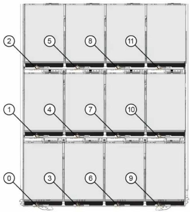
| Location LED | Status indicator and description | |
| 0 | Attention/Locate Drive LED 0 | Amber: The drive in the drawer requires operator attention.Off: The drive in the drawer is operating normally.Blinking: A locate operation for the drive is in progress. |
| 1 | Attention/Locate Drive LED 1 | |
| 2 | Attention/Locate Drive LED 2 | |
| 3 | Attention/Locate Drive LED 3 | |
| 4 | Attention/Locate Drive LED 4 | |
| 5 | Attention/Locate Drive LED 5 | |
| 6 | Attention/Locate Drive LED 6 | |
| 7 | Attention/Locate Drive LED 7 | |
| 8 | Attention/Locate Drive LED 8 | |
| 9 | Attention/Locate Drive LED 9 | |
| 10 | Attention/Locate Drive LED 10 | |
| 11 | Attention/Locate Drive LED 11 |
LEDs on the IOMs
In a duplex array, all DE120S, DE240S and DE600S drive shelves have two I/O modules (IOMs).
• Each IOM has an Attention LED and a Locate LED.
• Each IOM has four SAS ports, each with a Port Link LED and a Port Attention LED.
The following illustration shows the IOM LEDs.
Figure 57. IOM LEDs
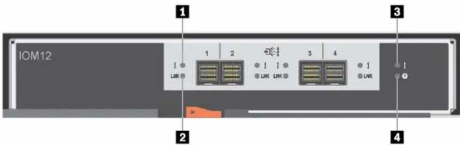
| LED | Status | Description |
| 1 SAS Port Attention | Amber | One or more of the links in the port are not working properly. |
| Off The port is optimal and no link error | has occurred. | |
| 2 SAS Port Link Green Th | the SAS port established a link (with | either a controller or another drive shelf). |
| Off No link is established to another SAS | port. | |
| 3 IOM Attention Amber Th | IOM is not functioning correctly. | |
| Off The IOM is functioning correctly. | ||
| 4 Locate Blue There is an | active request to | physically locate the drive shelf.Note:When this LED is activated, the Locate LED on the left end cap of the drive shelf is also activated.Locate LEDs turn off automatically after 30 minutes. |
| Off There is no active request to locate | the drive shelf. |
LEDs on the power-fan canister
The power-fan canister has LEDs and its own power switch and power outlet. Each 12-drive or 24-drive shelf has two of these canisters.
The following illustration shows the LEDs on the power-fan canister.

Figure 58. LEDs on the power-fan canister
| LED | Status | Description |
| Power LED Green The power supply is functioning | correctly. | |
| Off The power supply failed, the AC | ||
| Attention LED Amber The power supply has a fault, or | there is no input power to this power canister, but the other power canister is operating. | |
LEDs on the power canister
The power canister has LEDs and its own power switch and power outlet. Each DE4000H/DE6000H controller shelf and DE600S drive shelf contains two power canisters.
The following illustration shows the LEDs on the power canister.
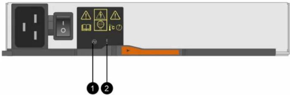
Figure 59. LEDs on the power canister
| LED | Status | Description |
| Power LED | Green The power supply is functioning | correctly. |
| Off The power supply failed, the AC | switch is turned off, the AC power cord is not properly installed, or the AC power cord input voltage is not within margin (there is a problem at the source end of the AC power cord). | |
| Attention LED Amber The power | supply has a fault, or | there is no input power to this power canister, but the other power canister is operating. |
LEDs on the fan canister
The fan canister has an Attention LED that is identified by a sideways exclamation point in the middle of the canister. Each 60-drive shelf contains two fan canisters, one on either side of the enclosure.
The following illustration shows the LEDs on the fan canister.
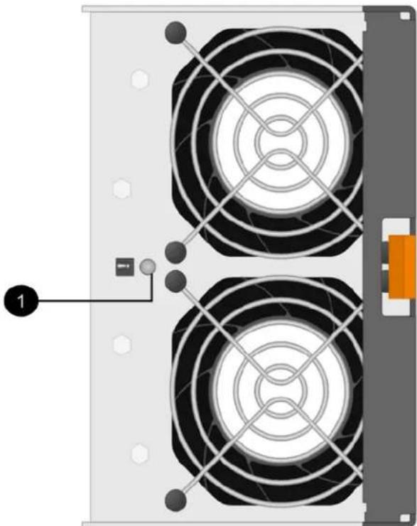
natural_image
Diagram of two circular electronic components with radial connections, no text or symbols presentFigure 60. LEDs on the fan canister
| LED | Status | Description |
| 1 Attention LED | Amber The fan has a fault. |
Seven-segment display overview
The DE2000/DE4000/DE6000 controllers have a two-digit, seven-segment display at the back, which shows the following information.
| Controller state | Seven-segment display |
| Functioning correctly Tray ID | |
| Not functioning correctly Diagnostic codes to help identify errors | |
The following figure shows the seven-segment display for the DE2000 controller shelf, the DE4000 controller shelf, and the DE6000 controller shelf.
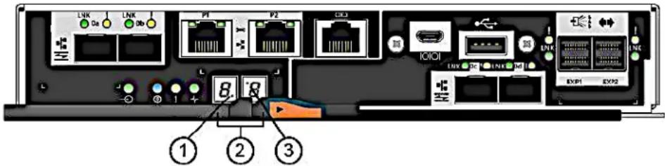
Figure 61. Seven-segment display
Note: Your controller model might be slightly different from the illustration.
The following table describes the seven-segment display and their operational states.
| LED | Status | Description |
| 1 Heartbeat (dot in the lower right) | Blinking green This indicates normal activity. | |
| 2 Tray ID | Green This shows the ID of the controller shelf when the controller operates normally. If the controller is not operating normally and the Diagnostic LED is on, the diagnostic code is displayed instead. | |
| 3 Diagnostic (dot in the upper left) | Green | The seven-segment display shows the diagnostic code. |
| Off The seven-segment display shows the tray ID. | ||
Seven-segment display sequence codes
Seven-segment display sequences enable you to understand errors and operational states of the various components in your storage array. Each sequence shows a two-digit category code, followed by a two-digit detail code. The category code appears at the start of a sequence and the detail code follows the category code with more specific information about the error. After each category code is displayed, the LED goes blank. The detail code then appears and disappears, and the entire sequence is repeated. For example, if there is a power-on validation error during startup, you see the following codes displayed on the seven-segment display: SE, followed by Sx, in which SE is the category code and Sx is the detail code.
When the seven-segment display sequence starts, the Diagnostic LED is on (green).
The following table includes the seven-segment display sequence codes and descriptions:
| Category Category code | Detail code | |
| Startup error SE | 88: Power-on defaultdF: Power-on diagnostic faultSx: Power-on validation error | |
| Operational error OE | Lx: Lock-down codesSee “Seven-segment display lock-down codes” on page 230. | |
| Operational state OS | OL: Offlinebb: Battery backup (operating on batteries)OH: CPU temperature exceeds the warning levelCF: Component failure | |
| Component failure CF | dx: Processor or cache DIMMCx: Cache DIMMPx: Processor DIMMHx: Host interface cardFx: Flash drivebl: Base controller card | |
| Diagnostic failure dE | Lx: Lock-down codesSee “Seven-segment display lock-down codes” on page 230. | |
| Category delimiter | --The double hyphen (--) is the separator between category-detail code pairs when more than one pair exists in the sequence. | |
| End-of-sequence delimiter Blank; display turns off at the end of a sequence | ||
Seven-segment display codes when controller turns on
The following table describes the seven-segment codes that are displayed when the controller turns on:
| Code | Description |
| 0xEA DDR4 training failed | |
| 0xE8 No memory installed | |
| 0x22 No master boot record found on any boot device | |
| 0x23 | No SATA drive installed |
| 0xAE | Booting OS |
| 0xAB Alternate boot code | |
| 0x40 Invalid DIMMs | |
| 0x41 Invalid DIMMs | |
| 0x42 Memory test failed | |
| 0x2A, 0x2B | Stuck bus, unable to read DIMM SPD data |
| 0x51 | DIMM SPD read failure |
| 0xA0, 0xA1, 0xA2, and 0xA3 | SATA drive initialization |
| 0x92 – 0x96 | PCI bus initialization |
Seven-segment display use cases
The following table shows seven-segment display use cases and the sequence that is displayed in each case:
| Use case | Display sequence |
| Controller power-on | |
| • Normal power-on controller insertion• Controller inserted while held in reset | SE 88 blank |
| Operational states | |
| Normal operation | xy (static controller tray ID) |
| Start-of-day (SOD) processing OS Sd blank | |
| The controller is placed in reset while showing the tray ID OS OL blank | |
| The controller is operating on batteries (cache backup) OS bb blank | |
| The CPU temperature has exceeded the warning level OS OH blank | |
| Component failure when the controller is operational | |
| Failed host interface card (HIC) OS CF HX blank | |
| Failed flash drive OS CF Fx blank | |
| Power-on diagnostic failure | |
| Failure of a component that is not a field replaceable unit SE dF blank- | |
| Processor DIMM failure SE dF -- CF Px blank- | |
| Cache memory DIMM failure SE dF -- CF Cx blank- | |
| Processor DIMM or cache memory DIMM failure SE dF -- CF dx blank- | |
| Host interface card failure SE dF -- CF Hx blank- | |
| Incorrect number of cache backup devices SE LC -- CF Fx blank- | |
| The controller is suspended and there are no other errors to report | |
| All lock-down conditions | OH Lx blank- |
| The controller is suspended because of component errors | |
| Persistent processor DIMM error correcting code (ECC) errors | OE L2 -- CF Px blank- |
| Persistent cache DIMM ECC errors | OE L2 -- CF Cx blank- |
| Persistent processor or cache DIMM ECC errors | OE L2 -- CF dx blank- |
| The controller is suspended as a result of persistent cache backup configuration errors | |
| The write-protect switch is set during cache restore OE LC blank- | |
| The memory size changed with dirty data in the flash drives OE L2 -- CF | dx blank- |
| The controller is suspended as a result of diagnostic errors | |
| Cache memory diagnostic failure dE L2 -- CF Cx blank- | |
| Base controller diagnostic failure dE L3 -- CF b1 blank- | |
| Base controller I/O Controller chip (IOC) diagnostic failure dE L3 -- CF b2 | blank- |
Seven-segment display lock-down codes
Diagnostic lock-down codes are displayed when the controller is not operational, either because of a configuration problem or a hardware fault. The lock-down code is displayed as part of the seven-segment display sequence.
The following table includes the lock-down codes and describes the conditions that cause the controller to be in a suspended state:
| Lock-down code | Description |
| L0 The controller types | in a two-controller configuration are mismatched. |
| L1 Missing interconnect canister. | |
| L2 A persistent memory error has occurred. | |
| L3 A persistent hardware error has occurred. | |
| L4 A persistent data protection error has occurred. | |
| L5 An auto-code synchronization (ACS) failure has been detected. | |
| L6 | An unsupported HIC has been detected. |
| L7 A sub-model identifier either has not been set or has been mismatched. | |
| L8 A memory configuration error has occurred. | |
| L9 | A link speed mismatch condition has been detected in either the I/O module (IOM) or the power supply. |
| Lb | A HIC configuration error has been detected. |
| LC A persistent cache backup configuration error has been detected. | |
| Ld A mixed cache memory DIMMs condition has been detected. | |
| LE Uncertified cache memory DIMM sizes have been detected. | |
| LF | The controller has locked down in a suspended state with limited SYMBOL support. |
| LH Controller in Simplex Mode installed in the wrong slot. | |
| LJ The controller does not have enough memory to support the configuration. | |
| LL | The controller cannot access either midplane SBB EEPROM. |
| Ln A module is not valid for a controller. | |
| LP Drive port mapping tables are not detected. | |
| Lr A component that is not a field replaceable unit (FRU) has been replaced. | |
| Lt A configuration data | base corruption has been detected. |
| LU | The SOD reboot limit has been exceeded. |
In some cases, controllers detect errors during the startup process. The following table describes seven-segment startup errors and conditions that result in the controller being in a suspended state:
| Startup error code Description | |
| S1 The controller detects a checksum failure in EEPROM. | |
| S2 The SBB Signature | Revision is invalid. |
| S3 | An unsupported enclosure is detected in the storage array. |
| S4 The power supplies | are incapable of powering the controller. |
| S5 The SBB pairing has failed. | |
Critical Events Reference
Critical events from DE Series arrays display certain defined fields in the alert and SNMP trap messages.
Storage array alert traps
When a critical Major Event Log (MEL) event is generated, the embedded SNMP agent delivers a storage array alert trap to all configured trap destinations. This message contains the following data:
| MIB variable field Description | |
| Storage array name Storage array user label. If the label contains non-ASCII characters, the resulting variable binding is populated with the fixed string "NonASCII Name." If the label is blank, the variable binding is populated with the fixed string "Unnamed." | |
| Event type | Event Code (4-digit hexadecimal) for the particular MEL event that prompted the trap. |
| Event time | Timestamp of event in MM/DD/YYYY HH:MM:SS (24-hour clock) format. Note this is always controller/GMT time. |
| Event description Description of the specific MEL event that prompted the trap. | |
| Event component type String representation of component type for the MEL vent that prompted the trap. Defaults to "Not Available" if component type cannot be identified. | |
| Event component location | This data is not populated by the embedded SNMP agent running on the controller at this time. |
| Event severity String representation of the severity of the MEL event that prompted the trap. Defaults to "Unknown" if severity cannot be identified. | |
| Event priority | String representation of the priority of the MEL event that prompted the trap. Defaults to "Unknown" if priority cannot be identified. |
| Storage array WWID 32-character printable ASCII representation of the 16-byte Storage Array World Wide Name. | |
| Chassis serial number 32-character printable ASCII representation of the 16-byte Storage array World Wide Name. | |
Critical event data
Critical event data from DE Series arrays is shown below:
MEL\_EV\_DRIVE\_PFA - 0x1010
This event occurs when: The logged device generated a PFA condition.
Event Name - Drive PFA
Event description: Impending drive failure detected by drive
Event Group - Destination Driver
Event Priority - CRITICAL_EVENT
Log Group - Controller (0x1)
Event Category - Error (0x1)
Event Component Type - Drive (0x0, 0x1)
Event Specific Data - Optional data is provided with this event. MEL_DATA_DRIVE_CDB
RecoveryFailureType - REC_IMPENDING_DRIVE_FAILURE_RISK_HIGH (impendingDriveFailureHigh.html), REC_IMPENDING_DRIVE_FAILURE_RISK_MED (impendingDriveFailureMed.html)
MEL\_EV\_SYNTH\_DRIVE\_PFA - 0x101E
This event occurs when: The controller has detected that a drive failure is imminent.
Event Name - Synth Drv PFA
Event description: Impending drive failure detected by controller
Event Group - Destination Driver
Event Priority - CRITICAL_EVENT
Log Group - Drive (0x2)
Event Category - Error (0x1)
Event Component Type - Drive (0x0, 0x1)
Event Specific Data - Optional data is provided with this event. MEL_DATA_DRIVE_SPFA_STATS
RecoveryFailureType - REC_IMPENDING_DRIVE_FAILURE_RISK_LOW ( impendingDriveFailureLow.html )
MEL\_EV\_PI\_DRIVE\_LOCKED\_OUT - 0x1020
This event occurs when: An incompatible Protection Information drive has been discovered.
Event Name - PI Drive Locked Out
Event description: Data assurance drive has been locked out
Event Group - Destination Driver
Event Priority - CRITICAL_EVENT
Log Group - Drive (0x2)
Event Category - State (0x5)
Event Component Type - Drive (0x0, 0x1)
Event Specific Data - Optional data is not provided with this event.
RecoveryFailureType - REC_DRIVE_INCOMPATIBLE_PI_TYPE (driveIncompatiblePIType.html)
MEL\_EV\_FC\_LINK\_ERROR\_THRESHOLD\_CRITICAL - 0x1207
This event occurs when: A Link Error count exceeds the threshold the first time.
Event Name - Link Error Threshold Critical
Event description: Fibre channel link errors - threshold exceeded
Event Group - Fibre Channel Source Driver
Event Priority - CRITICAL_EVENT
Log Group - Controller (0x1)
Event Category - Error (0x1)
Event Component Type - Channel (0x0, 0x6)
Event Specific Data - Optional data is not provided with this event.
RecoveryFailureType - N/A
MEL\_EV\_FC\_SPEED\_NEG\_FAILURE - 0x1208
This event occurs when: A data rate negotiation fails.
Event Name - FC Speed Neg Failure
Event description: Data rate negotiation failed
Event Group - Fibre Channel Source Driver
Event Priority - CRITICAL_EVENT
Log Group - Controller (0x1)
Event Category - Error (0x1)
Event Component Type - Channel (0x0, 0x6)
Event Specific Data - Optional data is not provided with this event.
RecoveryFailureType - N/A
MEL\_EV\_DEGRADE\_CHANNEL - 0x1209
This event occurs when: A drive channel is set to degraded.
Event Name - Degrade Channel
Event description: Drive channel set to Degraded
Event Group - Fibre Channel Source Driver
Event Priority - CRITICAL_EVENT
Log Group - Controller (0x1)
Event Category - Error (0x1)
Event Component Type - Channel (0x0, 0x6)
Event Specific Data - Optional data is provided with this event. MEL_DATA_DDS_RECORD
RecoveryFailureType - REC_CHANNEL_DEGRADED ( degradedDriveChannel.html )
MEL\_EV\_FC\_SFP\_FAILED - 0x120A
This event occurs when: The SFP on an XBB class controller has failed.
Event Name - SFP Failed
Event description: SFP failed
Event Group - Fibre Channel Source Driver
Event Priority - CRITICAL_EVENT
Log Group - System (0x0)
Event Category - Error (0x1)
Event Component Type - Controller SFP (0x2, 0x8)
Event Specific Data - Optional data is not provided with this event.
RecoveryFailureType - N/A
MEL\_EV\_FC\_HOST\_SFP\_FAILED - 0x120D
This event occurs when: The host side SFP on an XBB class controller has failed.
Event Name - Host Side SFP Failed
Event description: Host-side SFP failed
Event Group - Fibre Channel Source Driver
Event Priority - CRITICAL_EVENT
Log Group - System (0x0)
Event Category - Error (0x1)
Event Component Type - Controller SFP (0x2, 0x8)
Event Specific Data - Optional data is not provided with this event.
RecoveryFailureType - N/A
MEL\_EV\_EXCESSIVE\_REBOOTS\_DETECTED - 0x1403
This event occurs when: This event is logged when the number of times a controller reboots reaches a certain threshold in a certain time window.
Event Name - Excessive Reboots Detected
Event description: Excessive reboots (exceptions) have occurred on the controller
Event Group - System
Event Priority - CRITICAL_EVENT
Log Group - Controller (0x1)
Event Category - Error (0x1)
Event Component Type - Controller (0x0, 0x8)
Event Specific Data - Optional data is not provided with this event.
RecoveryFailureType - REC_EXCESSIVE_REBOOTS_DETECTED
MEL\_EV\_DFC\_ALT\_LOOP\_DIAG\_FAIL - 0x150E
This event occurs when: A loop or minihub diagnostics detect that the controller is the bad device on the loop.
Event Name - Loop Diagnostic Failure
Event description: Controller loop-back diagnostics failed
Event Group - Fibre Channel-specific Destination Driver
Event Priority - CRITICAL_EVENT
Log Group - System (0x0)
Event Category - Notification (0x4)
Event Component Type - Controller (0x0, 0x8)
Event Specific Data - Optional data is not provided with this event.
RecoveryFailureType - N/A
MEL\_EV\_DFC\_CHANNEL\_MISWIRE - 0x150F
This event occurs when: Two channels are connected with one or more ESMs in between.
Event Name - Channel Miswire
Event description: Channel miswire
Event Group - Fibre Channel-specific Destination Driver
Event Priority - CRITICAL_EVENT
Log Group - System (0x0)
Event Category - Error (0x1)
Event Component Type - Channel (0x0, 0x6)
Event Specific Data - Optional data is not provided with this event.
RecoveryFailureType - N/A
MEL\_EV\_DFC\_ESM\_MISWIRE - 0x1510
This event occurs when: Two IOMs (ESMs) of the same tray are seen on the same channel.
Event Name - ESM Miswire
Event description: IOM (ESM) miswire
Event Group - Fibre Channel-specific Destination Driver
Event Priority - CRITICAL_EVENT
Log Group - System (0x0)
Event Category - Error (0x1)
Event Component Type - Tray Component (ESM, GBIC/SFP, Power Supply, or Fan) (0x0, 0x7)
Event Specific Data - Optional data is provided with this event.
MEL_SYMBOL_DATA_TRAYNUMBER
RecoveryFailureType - REC_ESM_MISWIRE (esmMiswire.html)
MEL\_EV\_DFC\_CHANNEL\_FAILOVER - 0x1513
This event occurs when: A drive fails.
Event Name - Channel Failover
Event description: Individual drive - Degraded path
Event Group - Fibre Channel-specific Destination Driver
Event Priority - CRITICAL_EVENT
Log Group - System (0x0)
Event Category - Error (0x1)
Event Component Type - Channel (0x0, 0x6)
Event Specific Data - Optional data is provided with this event. MEL_DATA_CHANNEL_LOCATION
RecoveryFailureType - REC_PATH_DEGRADED ( degradedDrivePath.html )
MEL\_EV\_DFC\_HW\_FAILED\_CHANNEL - 0x1515
This event occurs when: A drive channel hardware fails.
Event Name - Drive Channel Hardware Failed
Event description: Drive Channel hardware failed
Event Group - Fibre Channel-specific Destination Driver
Event Priority - CRITICAL_EVENT
Log Group - Controller (0x1)
Event Category - Error (0x1)
Event Component Type - Channel (0x0, 0x6)
Event Specific Data - Optional data is provided with this event. MEL_DATA_DDS_RECORD
RecoveryFailureType - N/A
MEL\_EV\_DFC\_LSD\_FAILURE - 0x151A
This event occurs when: A drive enclosure attached to a channel port is set to a link speed not supported by the SFP, resulting in a port bypass. Could also be Are is a faulty SFP, cable, or ESM.
Event Name - Link Speed Detection Failure
Event description: Optical link speed detection failure
Event Group - Fibre Channel-specific Destination Driver
Event Priority - CRITICAL_EVENT
Log Group - System (0x0)
Event Category - Error (0x1)
Event Component Type - Channel (0x0, 0x6)
Event Specific Data - Optional data is not provided with this event.
RecoveryFailureType - REC_LINK_SPEED_DETECTION_MISMATCH ( dataRateMismatch.html )
MEL\_EV\_DFC\_CTL\_MISWIRE - 0x151E
This event occurs when: This error is logged only for controllers with integrated drive channel ports. When two ESMs in the same drive tray are connected to different channels from the same controller. This error is reported for both channel ports involved in the miswire.
Event Name - Controller Miswire
Event description: Controller miswire for drive channel occurred
Event Group - Fibre Channel-specific Destination Driver
Event Priority - CRITICAL_EVENT
Log Group - System (0x0)
Event Category - Error (0x1)
Event Component Type - Channel Port (0x2, 0x3)
Event Specific Data - Optional data is not provided with this event.
RecoveryFailureType - N/A
MEL\_EV\_DFC\_MIXED\_LOOP\_TECHNOLOGY\_MISWIRE - 0x1522
This event occurs when: Information not available.
Event Name - Drive Enclosure Type Miswire
Event description: Drive enclosure type miswire
Event Group - Fibre Channel-specific Destination Driver
Event Priority - CRITICAL_EVENT
Log Group - System (0x0)
Event Category - Notification (0x4)
Event Component Type - Enclosure (0x0, 0xA)
Event Specific Data - Optional data is provided with this event.
MEL_SYMBOL_DATA_TRAYNUMBER
RecoveryFailureType - REC_MIXED_DRIVE_ENCLOSURE_MISWIRE (mixedDriveTrayMiswire.html)
MEL\_EV\_DFC\_TRUNK\_INCOMPATIBLE\_ESM - 0x1524
This event occurs when: The drive channel is trunk capable but an IOM (ESM) is determined to be trunk incompatible. This event is logged for each IOM (ESM) that is trunk incompatible.
Event Name - Trunk Incompatible ESM
Event description: Trunk incompatible IOM (ESM)
Event Group - Fibre Channel-specific Destination Driver
Event Priority - CRITICAL_EVENT
Log Group - System (0x0)
Event Category - Notification (0x4)
Event Component Type - Tray Component (ESM, GBIC/SFP, Power Supply, or Fan) (0x0, 0x7)
Event Specific Data - Optional data is provided with this event. MEL_SYMBOL_DATA_TRAYNUMBER
RecoveryFailureType - REC_FIBRE_TRUNC_INCOMPATIBLE_ESM (fcTrunkingIncompatibleEsm.html)
MEL\_EV\_DFC\_FIBRE\_TRUNK\_MISWIRE - 0x1525
This event occurs when: Drive enclosures are trunk capable but are not cabled correctly for trunking or the cables themselves are missing. There should be one MEL event logged irrespective of the number of devices in miswire.
Event Name - Fibre Trunk Miswire
Event description: Fibre trunk miswire
Event Group - Fibre Channel-specific Destination Driver
Event Priority - CRITICAL_EVENT
Log Group - System (0x0)
Event Category - Notification (0x4)
Event Component Type - Channel (0x0, 0x6)
Event Specific Data - Optional data is not provided with this event.
RecoveryFailureType - REC_FIBRE_TRUNC_MISWIRE (fcTrunkingMiswire.html)
MEL\_EV\_SAS\_FRNT\_END\_MISWIRE - 0x1650
This event occurs when: Two ESMs or controllers, residing in the same tray, are cabled together.
Event Name - SAS Front End Miswire
Event description: SAS host channel miswire detected
Event Group - SAS-Specific Source Driver and Miscellaneous
Event Priority - CRITICAL_EVENT
Log Group - System (0x0)
Event Category - Error (0x1)
Event Component Type - Channel (0x0, 0x6)
Event Specific Data - Optional data is not provided with this event.
RecoveryFailureType - REC_SAS_PORT_MISWIRED (SASMiswire.html)
MEL\_EV\_SAS\_PARTNER\_INITIATOR\_OVERFLOW - 0x1652
This event occurs when: A SAS source driver detects an initiator overflow condition resulting in the partner controller being unable to communicate with the SAS backend elements. This event is only logged on SAS-1 controllers (Mary Jane and Winterpark).
Event Name - Initiator Overflow
Event description: SAS source driver partner initiator overflow
Event Group - SAS-Specific Source Driver and Miscellaneous
Event Priority - CRITICAL_EVENT
Log Group - Controller (0x1)
Event Category - Failure (0x2)
Event Component Type - Controller (0x0, 0x8)
Event Specific Data - Optional data is provided with this event.
MEL_DATA_DEVICE_NAME
RecoveryFailureType - N/A
MEL\_EV\_SAS\_HOST\_WIDE\_PORT\_DEGRADED - 0x1654
This event occurs when: One of the host port physical devices goes down from the optimal state.
Event Name - Host Wide Port Degraded
Event description: Host wide port is degraded
Event Group - SAS-Specific Source Driver and Miscellaneous
Event Priority - CRITICAL_EVENT
Log Group - Controller (0x1)
Event Category - State (0x5)
Event Component Type - Controller (0x0, 0x8)
Event Specific Data - Optional data is not provided with this event.
RecoveryFailureType - N/A
MEL\_EV\_SAS\_BACKEND\_DISCOVERY\_ERROR - 0x165A
This event occurs when: The event is logged when a connectivity error has been detected during the SAS backend discovery processing. The error means that there has been a loss of redundancy with the connectivity to trays and/or drives.
Event Name - SAS Backend Discovery Error
Event description: An error has been detected during SAS backend discovery processing
Event Group - SAS-Specific Source Driver and Miscellaneous
Event Priority - CRITICAL_EVENT
Log Group - Controller (0x1)
Event Category - Error (0x1)
Event Component Type - Controller (0x0, 0x8)
Event Specific Data - Optional data is not provided with this event.
RecoveryFailureType - N/A
MEL\_EV\_DSAS\_TOPOLOGY\_MISWIRE - 0x1700
This event occurs when: A RAID controller detects an invalid SAS topology, such as an expander PHY with a table routing attribute attached to another expander PHY with a table routing attribute, a SAS loop, or multiple ports with the same SAS address.
Event Name - DSAS Topology Miswire
Event description: Invalid SAS topology detected
Event Group - SAS-Specific Destination Driver
Event Priority - CRITICAL_EVENT
Log Group - System (0x0)
Event Category - Error (0x1)
Event Component Type - Tray Component (ESM, GBIC/SFP, Power Supply, or Fan) (0x0, 0x7)
Event Specific Data - Optional data is not provided with this event.
RecoveryFailureType - REC_SAS_PORT_MISWIRED (SASMiswire.html), REC_SAS_LOOP_MISWIRE (SASLoopMiswire.html)
MEL\_EV\_DSAS\_BK\_END\_HBA\_MISWIRE - 0x1702
This event occurs when: A RAID controller detects a SAS adapter miswire.
Event Name - DSAS Back End HBA Miswire
Event description: SAS host adapter miswire detected
Event Group - SAS-Specific Destination Driver
Event Priority - CRITICAL_EVENT
Log Group - System (0x0)
Event Category - Error (0x1)
Event Component Type - Tray Component (ESM, GBIC/SFP, Power Supply, or Fan) (0x0, 0x7)
Event Specific Data - Optional data is not provided with this event.
RecoveryFailureType - REC_SAS_PORT_MISWIRED (SASMiswire.html), REC_SAS_HOST_MISWIRE (SASHostMiswire.html)
MEL\_EV\_DSAS\_ESM\_MISWIRE - 0x1704
This event occurs when: A RAID controller detects a SAS IOM (ESM) miswire.
Event Name - DSAS ESM Miswire
Event description: SAS IOM (ESM) miswire detected
Event Group - SAS-Specific Destination Driver
Event Priority - CRITICAL_EVENT
Log Group - System (0x0)
Event Category - Error (0x1)
Event Component Type - Tray Component (ESM, GBIC/SFP, Power Supply, or Fan) (0x0, 0x7)
Event Specific Data - Optional data is not provided with this event.
RecoveryFailureType - REC_SAS_PORT_MISWIRED (SASMiswire.html), REC_SAS_CROSS_MISWIRE (SASChannelMiswire.html)
MEL\_EV\_DSAS\_WPORT\_OPT\_TO\_DEG - 0x1706
This event occurs when: At least one of the phys that comprise a port is determined to be connected to an attached device, but the remaining port phys cannot connect to or communicate with an attached device.
Event Name - Optimal Wide Port Becomes Degraded
Event description: Optimal wide port becomes degraded
Event Group - SAS-Specific Destination Driver
Event Priority - CRITICAL_EVENT
Log Group - System (0x0)
Event Category - Error (0x1)
Event Component Type - Tray Component (ESM, GBIC/SFP, Power Supply, or Fan) (0x0, 0x7)
Event Specific Data - Optional data is provided with this event.
MEL_SYMBOL_DATA_SLOTNUMBER
RecoveryFailureType - REC_SAS_PORT_DEGRADED (failedSASPort.html)
MEL\_EV\_DSAS\_WPORT\_DEG\_TO\_FAIL - 0x1707
This event occurs when: An attached device is determined to be present, but none of the PHYs that comprise the port attached to that device can connect to or communicate with the device.
Event Name - Degraded Wide Port Becomes Failed
Event description: Degraded wide port becomes failed
Event Group - SAS-Specific Destination Driver
Event Priority - CRITICAL_EVENT
Log Group - System (0x0)
Event Category - Error (0x1)
Event Component Type - Tray Component (ESM, GBIC/SFP, Power Supply, or Fan) (0x0, 0x7)
Event Specific Data - Optional data is provided with this event.
MEL_SYMBOL_DATA_SLOTNUMBER
RecoveryFailureType - REC_SAS_PORT_FAILED (failedSASPort.html)
MEL\_EV\_DSAS\_EXP\_PORT\_DEV\_MISWIRE - 0x170A
This event occurs when: Information not available.
Event Name - DSAS Exp Port Dev Miswire
Event description: Drive expansion port miswire
Event Group - SAS-Specific Destination Driver
Event Priority - CRITICAL_EVENT
Log Group - System (0x0)
Event Category - Error (0x1)
Event Component Type - Tray Component (ESM, GBIC/SFP, Power Supply, or Fan) (0x0, 0x7)
Event Specific Data - Optional data is not provided with this event.
RecoveryFailureType - REC_SAS_PORT_MISWIRED (SASMiswire.html)
MEL\_EV\_DSAS\_WPORT\_OPT\_TO\_DEG\_CTLR - 0x170F
This event occurs when: At least one of the phys that comprise a port is determined to be connected to an attached device, but the remaining port phys cannot connect to or communicate with an attached device.
Event Name - Controller Wide Port Has Gone To Degraded State
Event description: Controller wide port has gone to degraded state
Event Group - SAS-Specific Destination Driver
Event Priority - CRITICAL_EVENT
Log Group - System (0x0)
Event Category - Error (0x1)
Event Component Type - Controller (0x0, 0x8)
Event Specific Data - Optional data is provided with this event. MEL_SYMBOL_DATA_SLOTNUMBER
RecoveryFailureType - REC_SAS_PORT_DEGRADED (failedSASPort.html)
MEL\_EV\_DSAS\_WPORT\_DEG\_TO\_FAIL\_CTLR - 0x1710
This event occurs when: A device attached to the controller is determined to be present, but none of the PHYs that comprise the port attached to that device can connect to or communicate with the device.
Event Name - Controller Wide Port Has Gone To Failed State
Event description: Controller wide port has gone to failed state
Event Group - SAS-Specific Destination Driver
Event Priority - CRITICAL_EVENT
Log Group - System (0x0)
Event Category - Error (0x1)
Event Component Type - Controller (0x0, 0x8)
Event Specific Data - Optional data is provided with this event. MEL_SYMBOL_DATA_SLOTNUMBER
RecoveryFailureType - REC_SAS_PORT_FAILED (failedSASPort.html)
MEL\_EV\_LOSS\_EXT\_REDUNDANCY - 0x171A
This event occurs when: A controller may have lost access to expansion trays.
Event Name - Loss of External Redundancy
Event description: A controller may have lost access to expansion trays
Event Group - SAS-Specific Destination Driver
Event Priority - CRITICAL_EVENT
Log Group - System (0x0)
Event Category - Error (0x1)
Event Component Type - Channel Port (0x2, 0x3)
Event Specific Data - Optional data is not provided with this event.
RecoveryFailureType - REC_LOSS_OF_EXTERNAL_REDUNDANCY (noExtRedundancy.html)
MEL\_EV\_ISCSI\_FAILED\_HOST\_CARD - 0x180A
This event occurs when: The firmware detects an iSCSI interface error. The optional data field of the MEL event includes information about the cause of the error, which, if Andrecht, Snowsnake, or Glencove HICS, includes (1) Uncorrectable ECC error, (2) The firmware cannot successfully restart the iSCSI interface, or (3) an iSCSI Controller EEPROM Error occurs. If Zion or Samoa HICS, the firmware cannot successfully restart the iSCSI interface.
Event Name - iSCSI Failed Host Card
Event description: Failed I/O host card; iSCSI interface error detected
Event Group - iSCSI-Specific
Event Priority - CRITICAL_EVENT
Log Group - System (0x0)
Event Category - Failure (0x2)
Event Component Type - Host Board (0x2, 0x5)
Event Specific Data - Optional data is not provided with this event.
RecoveryFailureType - REC_FAILED_HOST_IO_CARD (failedHostCard.html)
MEL\_EV\_FAILED\_HOST\_INTERFACE\_CARD - 0x1904
This event occurs when: The host interface card fails a loopback diagnostic test.
Event Name - Failed Host Interface Card
Event description: Failed host interface card
Event Group - Controller Field Replaceable HW
Event Priority - CRITICAL_EVENT
Log Group - Controller (0x1)
Event Category - Failure (0x2)
Event Component Type - Host I/O Card (0x2, 0xD)
Event Specific Data - Optional data is provided with this event. MEL_SYMBOL_DATA_SLOTNUMBER
RecoveryFailureType - REC_HOST_BOARD_FAULT (hostCardFault.html)
MEL\_EV\_MISSING\_DRIVE\_LOCKDOWN - 0x1907
This event occurs when: A controller is locked down due to detecting enough missing drives that if left alone would result in failed volumes.
Event Name - Missing Drive Lockdown
Event description: Controller is locked down due to too many missing drives
Event Group - Controller Field Replaceable HW
Event Priority - CRITICAL_EVENT
Log Group - Controller (0x1)
Event Category - Error (0x1)
Event Component Type - Controller (0x0, 0x8)
Event Specific Data - Optional data is not provided with this event.
RecoveryFailureType - REC_MISSING_DRIVE_LOCKDOWN ( missingDrivesLockdown.html )
MEL\_EV\_HIC\_CONFIGURATION\_OOC - 0x1908
This event occurs when: A controller has detected that the combination of host interface cards are out of compliance with limitations of the controller and/or the firmware.
Event Name - HIC Configuration OOC
Event description: A controller has detected that the combination of host interface cards are out of compliance with limitations of the controller and/or the firmware.
Event Group - Controller Field Replaceable HW
Event Priority - CRITICAL_EVENT
Log Group - Controller (0x1)
Event Category - Error (0x1)
Event Component Type - Controller (0x0, 0x8)
Event Specific Data - Optional data is not provided with this event.
RecoveryFailureType - REC_HIC_CONFIGURATION_OOC
MEL\_EV\_DATA\_PARITY\_MISMATCH - 0x200A
This event occurs when: A data/parity mismatch is detected during data scrubbing.
Event Name - Data Parity Mismatch
Event description: Data/parity mismatch on volume
Event Group - VDD
Event Priority - CRITICAL_EVENT
Log Group - System (0x0)
Event Category - Error (0x1)
Event Component Type - Volume (0x0, 0xD)
Event Specific Data - Optional data is provided with this event. MEL_DATA_PARITY_READ_LBA
RecoveryFailureType - N/A
MEL\_EV\_MISCCORRECTED\_DATA - 0x202E
This event occurs when: An Unrecoverable Read Error is detected.
Event Name - Miscorrected Data
Event description: Read drive error during interrupted write
Event Group - VDD
Event Priority - CRITICAL_EVENT
Log Group - System (0x0)
Event Category - Notification (0x4)
Event Component Type - Controller (0x0, 0x8)
Event Specific Data - Optional data is provided with this event. MEL_DATA_LBA_INFO
RecoveryFailureType - N/A
MEL\_EV\_DRIVE\_FAIL\_READ\_ERROR\_SCAN\_CYCLE - 0x203B
This event occurs when: A drive is failed due to an unrecoverable read error detected during scan cycle.
Event Name - Drive Failure From Un-Recoverable Read Error
Event description: Drive failed due to un-recoverable read error during scan
Event Group - VDD
Event Priority - CRITICAL_EVENT
Log Group - Controller (0x1)
Event Category - Failure (0x2)
Event Component Type - Controller (0x0, 0x8)
Event Specific Data - Optional data is not provided with this event.
RecoveryFailureType - REC_FAILED_DRIVE (failedDrive.html)
MEL\_EV\_REDUN\_GROUP\_NOT\_CONSISTENT - 0x2045
This event occurs when: As part of a reconfiguration operation, a redundancy group is determined to be inconsistent. After the reconfiguration operation completes, the data will be consistent but the data may be corrupt.
Event Name - Redundancy Group Not Consistent During Reconfiguration
Event description: Redundancy group not consistent during reconfiguration
Event Group - VDD
Event Priority - CRITICAL_EVENT
Log Group - System (0x0)
Event Category - Notification (0x4)
Event Component Type - Volume (0x0, 0xD)
Event Specific Data - Optional data is provided with this event. MEL_DATA_PARITY_READ_LBA
RecoveryFailureType - REC_REDUNDANCY_GROUP_NOT_CONSISTENT_DURING_RECONFIG (RedundancyGroupInconsistency.html)
MEL\_EV\_ISOLATION\_REDUN\_MISMATCH - 0x2046
This event occurs when: In RAID 6 environments, via media scan with redundancy check or when pre-read redundancy check is enabled. The event is logged when a drive can be isolated as causing corruption using P and Q parity of RAID 6. In this event data on disk is not altered as correction action without the potential of corruption is ambiguous.
Event Name - Isolation Redundancy Mismatch
Event description: Isolation of drive causing redundancy mismatch
Event Group - VDD
Event Priority - CRITICAL_EVENT
Log Group - System (0x0)
Event Category - Notification (0x4)
Event Component Type - Drive (0x0, 0x1)
Event Specific Data - Optional data is provided with this event. MEL_DATA_REDUNDANCY_MISMATCH_DETECTED
RecoveryFailureType - N/A
MEL\_EV\_DIFFERENT\_DATA\_RETURNED\_ON\_RETRY - 0x2047
This event occurs when: A redundancy check results in retried reads and the drive returns different data on the retry.
Event Name - Different Data Returned On Retry
Event description: Different Data Returned On Read Retry
Event Group - VDD
Event Priority - CRITICAL_EVENT
Log Group - System (0x0)
Event Category - Notification (0x4)
Event Component Type - Drive (0x0, 0x1)
Event Specific Data - Optional data is provided with this event. MEL_DATA_DIFFERENT_DATA_RETURNED_ON_RETRY
RecoveryFailureType - N/A
MEL\_EV\_DATA\_ALtered\_TO\_CORRECT\_REDUN\_MISMATCH - 0x2048
This event occurs when: Data is altered due to a detected inconsistency in redundancy. The data, which was within a redundancy group with multiple redundancy (e.g. RAID 6), was isolated, recovered, and rewritten to the drive.
Event Name - Data Altered to Correct Redundancy Mismatch
Event description: Data altered to correct redundancy mismatch
Event Group - VDD
Event Priority - CRITICAL_EVENT
Log Group - System (0x0)
Event Category - Notification (0x4)
Event Component Type - Drive (0x0, 0x1)
Event Specific Data - Optional data is provided with this event. MEL_DATA_REDUNDANCY_MISMATCH_DETECTED
RecoveryFailureType - N/A
MEL\_EV\_PI\_SERVICE\_MODE\_ENTERED - 0x2069
This event occurs when: This event is logged when the controller has been rebooted into Service Mode because the controller has detected excessive Data Assurance errors.
Event Name - Data Assurance Service Mode Entered
Event description: Controller is in Service Mode due to excessive Data Assurance errors
Event Group - Protection Information
Event Priority - CRITICAL_EVENT
Log Group - Controller (0x1)
Event Category - Notification (0x4)
Event Component Type - Controller (0x0, 0x8)
Event Specific Data - Optional data is not provided with this event.
RecoveryFailureType - REC_PI_ERROR_SERVICE_MODE
MEL\_EV\_PI\_ANALYSIS\_LOCKDOWN\_MODE\_ENTERED - 0x206A
This event occurs when: This event is logged when the controller has been rebooted into Analysis Lockdown Mode because the controller has detected excessive Data Assurance errors.
Event Name - Data Assurance Analysis Lockdown Mode Entered
Event description: Controller is in Analysis Lockdown Mode due to excessive Data Assurance errors
Event Group - Protection Information
Event Priority - CRITICAL_EVENT
Log Group - Controller (0x1)
Event Category - Notification (0x4)
Event Component Type - Controller (0x0, 0x8)
Event Specific Data - Optional data is not provided with this event.
RecoveryFailureType - REC_PI_ERROR_LOCKDOWN
MEL\_EV\_CCM\_HW\_MISMATCH - 0x2109
This event occurs when: A write back cache could not be enabled due to different cache sizes of the controllers in the subsystem. ASC/ASCQ value of 0xA1/0x00 is also logged with this event.
Event Name - CCM Hardware Mismatch
Event description: Controller cache not enabled - cache sizes do not match
Event Group - Cache Manager
Event Priority - CRITICAL_EVENT
Log Group - System (0x0)
Event Category - Error (0x1)
Event Component Type - Controller (0x0, 0x8)
Event Specific Data - Optional data is provided with this event. MEL_DATA_LBA_INFO
RecoveryFailureType - REC_CACHE_MEM_SIZE_MISMATCH (cacheMismatch.html)
MEL\_EV\_CACHE\_BATTERY\_FAILURE - 0x210C
This event occurs when: A cache battery has failed. ASC/ASCQ of 0x0C/0x00 is also logged with this event.
Event Name - Cache Battery Failure
Event description: Controller cache battery failed
Event Group - Cache Manager
Event Priority - CRITICAL_EVENT
Log Group - System (0x0)
Event Category - Notification (0x4)
Event Component Type - Battery Pack (0x0, 0x9)
Event Specific Data - Optional data is provided with this event. MEL_DATA_SMART_BATTERY
RecoveryFailureType - REC_FAILED_BATTERY (failedBattery.html)
MEL\_EV\_CACHE\_DATA\_LOSS - 0x210E
This event occurs when: Logged by cache manager when cache blocks can't be successfully recovered. Companion to an ASC/ASCQ status of 0x0C/0x81.
Event Name - Cache Data Loss
Event description: Controller cache memory recovery failed after power cycle or reset
Event Group - Cache Manager
Event Priority - CRITICAL_EVENT
Log Group - Controller (0x1)
Event Category - Error (0x1)
Event Component Type - Controller (0x0, 0x8)
Event Specific Data - Optional data is provided with this event. MEL_DATA_LBA_INFO
RecoveryFailureType - REC_CACHE_DATA_LOSS ( cache_failed_data_loss.html )
MEL\_EV\_CACHE\_MEM\_DIAG\_FAIL - 0x2110
This event occurs when: A persistent RPA Memory Parity error is detected. A test of the cache memory (the data buffer on the controller) fails. The test is initiated with the startCacheMemoryDiagnostic_1 SYMbolAPI command. When the error occurs, the controller logs this event and locks down.
Event Name - Cache Memory Diagnostic Fail
Event description: Controller cache memory initialization failed
Event Group - Cache Manager
Event Priority - CRITICAL_EVENT
Log Group - System (0x0)
Event Category - Failure (0x2)
Event Component Type - Controller (0x0, 0x8)
Event Specific Data - Optional data is not provided with this event.
RecoveryFailureType - N/A
MEL\_EV\_CACHE\_BATTERY\_WARN - 0x2113
This event occurs when: A cache battery is within the specified number of weeks of failing. The ASC/ASCQ value of 0x3F/0xD9 is also logged with this event.
Event Name - Cache Battery Warning
Event description: Controller cache battery nearing expiration
Event Group - Cache Manager
Event Priority - CRITICAL_EVENT
Log Group - System (0x0)
Event Category - Error (0x1)
Event Component Type - Battery Pack (0x0, 0x9)
Event Specific Data - Optional data is provided with this event.
MEL_DATA_SMART_BATTERY
RecoveryFailureType - REC_BATTERY_NEAR_EXPIRATION (batteryNearExpiration.html)
MEL\_EV\_OCB\_SETTING\_CONFLICT - 0x211B
This event occurs when: A conflict is detected between the NVSRAM setting and the presence of batteries.
Event Name - OCB Setting Conflict
Event description: Batteries present but NVSRAM file configured for no batteries
Event Group - Cache Manager
Event Priority - CRITICAL_EVENT
Log Group - System (0x0)
Event Category - Notification (0x4)
Event Component Type - Battery Pack (0x0, 0x9)
Event Specific Data - Optional data is not provided with this event.
RecoveryFailureType - REC_BATTERY_CONFIG_MISMATCH (batterySettingsMismatch.html)
MEL\_EV\_UNSUPPORTED\_CACHE\_SIZE - 0x211E
This event occurs when: Controller is configured with an unsupported cache memory size.
Event Name - Unsupported Cache Size
Event description: Current cache size is unsupported
Event Group - Cache Manager
Event Priority - CRITICAL_EVENT
Log Group - System (0x0)
Event Category - Error (0x1)
Event Component Type - Controller (0x0, 0x8)
Event Specific Data - Optional data is not provided with this event.
RecoveryFailureType - REC_UNSUPPORTED_CACHE_MEMORY_SIZE ( unsupportedCacheMemSize.html )
MEL\_EV\_CACHE\_BACKUP\_INSUFFICIENT\_CAPACITY - 0x211F
This event occurs when: The cache backup device is missing, leaving insufficient capacity to perform full cache backup.
Event Name - Insufficient Backup Device Capacity
Event description: Insufficient cache backup device capacity
Event Group - Cache Manager
Event Priority - CRITICAL_EVENT
Log Group - System (0x0)
Event Category - Error (0x1)
Event Component Type - Controller (0x0, 0x8)
Event Specific Data - Optional data is not provided with this event.
RecoveryFailureType - REC_CACHE_BACKUP_DEVICE_INSUFFICIENT_CAPACITY (cacheBackupDevInsuffCapacity.html)
MEL\_EV\_INSUFFICIENT\_MEMORY\_FOR\_CACHE\_SIZE - 0x2120
This event occurs when: The controller has insufficient processor memory to support the configured cache.
Event Name - Insufficient Processor Memory For Cache
Event description: Insufficient processor memory for cache
Event Group - Cache Manager
Event Priority - CRITICAL_EVENT
Log Group - System (0x0)
Event Category - Error (0x1)
Event Component Type - Controller (0x0, 0x8)
Event Specific Data - Optional data is not provided with this event.
RecoveryFailureType - REC_PROC_MEM_TOO_SMALL_FOR_CACHE
MEL\_EV\_DEDICATED\_MIRROR\_CHANNEL\_FAILED - 0x2124
This event occurs when: Information not available.
Event Name - Dedicated Mirror Channel Failed
Event description: Dedicated mirror channel failed
Event Group - Cache Manager
Event Priority - CRITICAL_EVENT
Log Group - Controller (0x1)
Event Category - Failure (0x2)
Event Component Type - Controller (0x0, 0x8)
Event Specific Data - Optional data is not provided with this event.
RecoveryFailureType - REC_DEDICATED_MIRROR_CHANNEL_FAILED (failedDedicatedMirrorChannel.html)
MEL\_EV\_CACHE\_BACKUP\_PROTECTION\_ERROR - 0x2125
This event occurs when: A data integrity check failed when the cache data was being restored from the backup device.
Event Name - Cache Backup Protection Error
Event description: Integrity check failed during cache restore
Event Group - Cache Manager
Event Priority - CRITICAL_EVENT
Log Group - Controller (0x1)
Event Category - Failure (0x2)
Event Component Type - Controller (0x0, 0x8)
Event Specific Data - Optional data is not provided with this event.
RecoveryFailureType - N/A
MEL\_EV\_INCOMPLETE\_CACHE\_BACKUP - 0x2126
This event occurs when: The backup of the cache did not complete before the controller lost power -- input power and battery backup power.
Event Name - Incomplete Cache Backup
Event description: Backup of cache to persistent device did not complete
Event Group - Cache Manager
Event Priority - CRITICAL_EVENT
Log Group - Controller (0x1)
Event Category - Failure (0x2)
Event Component Type - Controller (0x0, 0x8)
Event Specific Data - Optional data is provided with this event. MEL_DATA_INC_BACKUP_REASON
RecoveryFailureType - N/A
MEL\_EV\_WB\_CACHING\_FORCIBLY\_DISABLED - 0x212B
This event occurs when: Write-back caching is forcibly disabled beyond a threshold period of time for volumes that are configured to use the write caching capability.
Event Name - Write-back Caching Forcibly Disabled
Event description: Write-back caching forcibly disabled
Event Group - Cache Manager
Event Priority - CRITICAL_EVENT
Log Group - System (0x0)
Event Category - Notification (0x4)
Event Component Type - Controller (0x0, 0x8)
Event Specific Data - Optional data is provided with this event. MEL_DATA_VOLUMES_INFO
RecoveryFailureType - REC_WB_CACHING_FORCIBLY_DISABLED (wBcacheDisabled.html)
MEL\_EV\_RCB\_CACHE\_DATA\_LOSS - 0x212E
This event occurs when: Recovery control block information has been lost either while restoring from a backup device or some other reason.
Event Name - Recovery Control Block Cache Data Loss
Event description: Cached data may have been lost
Event Group - Cache Manager
Event Priority - CRITICAL_EVENT
Log Group - Controller (0x1)
Event Category - Notification (0x4)
Event Component Type - Controller (0x0, 0x8)
Event Specific Data - Optional data is not provided with this event.
RecoveryFailureType - REC_CACHE_DATA_LOSS ( cache_failed_data_loss.html )
MEL\_EV\_CACHE\_NOT\_FLUSHED\_ON\_ONLY\_CTLR - 0x2131
This event occurs when: Logged when the alternate controller is held in reset and this controller fails to flush dirty cache data on failed volume(s) possibly due to offlined drives. The controller should not be replaced to avoid loss of data.
Event Name - Dirty Cache Not Flushed On The Only Active Controller
Event description: Dirty cache not flushed on the only active controller
Event Group - Cache Manager
Event Priority - CRITICAL_EVENT
Log Group - System (0x0)
Event Category - Notification (0x4)
Event Component Type - Controller (0x0, 0x8)
Event Specific Data - Optional data is not provided with this event.
RecoveryFailureType - REC_CACHE_NOT_FLUSHED_ON_ONLY_CTLR
MEL\_EV\_DEVICE\_FAIL - 0x222D
This event occurs when: A device is failed manually (via a SYMbolAPI command).
Event Name - Device Fail
Event description: Drive manually failed
Event Group - Configuration Manager
Event Priority - CRITICAL_EVENT
Log Group - Drive (0x2)
Event Category - Notification (0x4)
Event Component Type - Drive (0x0, 0x1)
Event Specific Data - Optional data is not provided with this event.
RecoveryFailureType - N/A
MEL\_EV\_CFG\_DRV\_TO\_SMALL - 0x2249
This event occurs when: A configuration manager posts an UA/AEN of ASC/ASCQ = 0x3F/0x8B indicating the controller set the drivestate to Drive Capacity is less than Minimum.
Event Name - CFG Drive Too Small
Event description: Physical drive replacement is too small
Event Group - Configuration Manager
Event Priority - CRITICAL_EVENT
Log Group - System (0x0)
Event Category - Notification (0x4)
Event Component Type - Drive (0x0, 0x1)
Event Specific Data - Optional data is provided with this event. MEL_DATA_DRV_REPLACE
RecoveryFailureType - N/A
MEL\_EV\_WRONG\_SECTOR\_SIZE - 0x224A
This event occurs when: A configuration manager posts an UA/AEN of ASC/ASCQ = 0x3F/0x8C indicating the controller set the drive state to Drive has wrong blocksize.
Event Name - Wrong Sector Size
Event description: Drive has wrong block size
Event Group - Configuration Manager
Event Priority - CRITICAL_EVENT
Log Group - System (0x0)
Event Category - Notification (0x4)
Event Component Type - Drive (0x0, 0x1)
Event Specific Data - Optional data is provided with this event. MEL_DATA_WRONG_SECTOR_SIZE
RecoveryFailureType - REC_DRIVE_INCOMPATIBLE_SECTOR_SIZE (sectorSizeIncompatible.html)
MEL\_EV\_DRV\_FORMAT\_FAILED - 0x224B
This event occurs when: A configuration manager posts an UA/AEN of ASC/ASCQ = 0x3F/0x86 indicating the controller set the drive state to Failed Format failure.
Event Name - Drive Format Failed
Event description: Drive failed - initialization failure
Event Group - Configuration Manager
Event Priority - CRITICAL_EVENT
Log Group - System (0x0)
Event Category - Notification (0x4)
Event Component Type - Drive (0x0, 0x1)
Event Specific Data - Optional data is not provided with this event.
RecoveryFailureType - N/A
MEL\_EV\_DRV\_NO\_RESPONSE - 0x224D
This event occurs when: A configuration manager posts an UA/AEN of ASC/ASCQ = 0x3F/0x85 indicating the controller set the drive state to Failed No Response.
Event Name - Drive No Response
Event description: Drive failed - no response at start of day
Event Group - Configuration Manager
Event Priority - CRITICAL_EVENT
Log Group - System (0x0)
Event Category - Notification (0x4)
Event Component Type - Drive (0x0, 0x1)
Event Specific Data - Optional data is not provided with this event.
RecoveryFailureType - REC_FAILED_DRIVE (failedDrive.html)
MEL\_EV\_RECON\_DRV\_FAILED - 0x224E
This event occurs when: A configuration manager posts an UA/AEN of ASC/ASCQ = 0x3F/0x82 indicating the controller set the drive state to Failed be it was unable to make the drive usable after replacement.
Event Name - Reconstruction Drive Failed
Event description: Drive failed - initialization/reconstruction failure
Event Group - Configuration Manager
Event Priority - CRITICAL_EVENT
Log Group - System (0x0)
Event Category - Failure (0x2)
Event Component Type - Drive (0x0, 0x1)
Event Specific Data - Optional data is not provided with this event.
RecoveryFailureType - N/A
MEL\_EV\_LUN\_DOWN - 0x2250
This event occurs when: A configuration manager posts an UA/AEN of ASC/ASCQ = 0x3F/0xE0 indicating Logical Unit Failure.
Event Name - LUN Down
Event description: Volume failure
Event Group - Configuration Manager
Event Priority - CRITICAL_EVENT
Log Group - System (0x0)
Event Category - Failure (0x2)
Event Component Type - Volume (0x0, 0xD)
Event Specific Data - Optional data is not provided with this event.
RecoveryFailureType - REC_FAILED_VOLUME (failedVolume.html)
MEL\_EV\_CFG\_READ\_FAIL - 0x2251
This event occurs when: A configuration manager posts an UA/AEN of ASC/ASCQ = 0x3F/0x8E indicating that the drive failed due to a reconstruction failure at SOD.
Event Name - CFG Read Failure
Event description: Drive failed - reconstruction failure
Event Group - Configuration Manager
Event Priority - CRITICAL_EVENT
Log Group - System (0x0)
Event Category - State (0x5)
Event Component Type - Drive (0x0, 0x1)
Event Specific Data - Optional data is not provided with this event.
RecoveryFailureType - N/A
MEL\_EV\_FAIL\_VDSK\_DELAYED - 0x2252
This event occurs when: A specified device is failed during interrupted write processing. SK/ASC/ASCQ = 0x06/0x3F/0x98 will be offloaded for each failing device.
Event Name - Fail Vdisk Delayed
Event description: Drive marked offline during interrupted write
Event Group - Configuration Manager
Event Priority - CRITICAL_EVENT
Log Group - System (0x0)
Event Category - Notification (0x4)
Event Component Type - Drive (0x0, 0x1)
Event Specific Data - Optional data is provided with this event. MEL_DATA_VOL_LABEL
RecoveryFailureType - N/A
MEL\_EV\_UNCERTIFIED\_DRIVE - 0x2260
This event occurs when: An uncertified drive has been detected in the array.
Event Name - Uncertified Drive
Event description: Uncertified Drive Detected
Event Group - Configuration Manager
Event Priority - CRITICAL_EVENT
Log Group - System (0x0)
Event Category - Notification (0x4)
Event Component Type - Drive (0x0, 0x1)
Event Specific Data - Optional data is not provided with this event.
RecoveryFailureType - REC_UNCERTIFIED_DRIVE ( uncertifiedDrive.html )
MEL\_EV\_CFG\_WRONG\_DRIVE\_TYPE - 0x2262
This event occurs when: A drive assigned to a volume group is failed, removed, and replaced with a drive that is not the same as the failed drive (for example, a Fibre Channel drive is replaced with a SATA drive).
Event Name - Configuration Wrong Drive Type
Event description: Failed drive replaced with wrong drive type
Event Group - Configuration Manager
Event Priority - CRITICAL_EVENT
Log Group - System (0x0)
Event Category - Notification (0x4)
Event Component Type - Drive (0x0, 0x1)
Event Specific Data - Optional data is not provided with this event.
RecoveryFailureType - REC_REPLACED_DRIVE_WRONG_TYPE (incorrectDriveType.html)
MEL\_EV\_RECONFIGURATION\_FAILED - 0x2266
This event occurs when: A drive fails during a reconfiguration operation causing the failure of all volumes in the volume group.
Event Name - Reconfiguration Failed
Event description: Volume modification operation failed
Event Group - Configuration Manager
Event Priority - CRITICAL_EVENT
Log Group - System (0x0)
Event Category - Failure (0x2)
Event Component Type - Volume Group (0x0, 0xE), Disk Pool (0x3, 0x2)
Event Specific Data - Optional data is provided with this event. MEL_SYMBOL_DATA_RETURNCODE
RecoveryFailureType - REC_FAILED_MODIFYING_VOLUME (failedModifyingVolume.html)
MEL\_EV\_INCOMPAT\_DRIVE\_INVALID\_CONFIG - 0x2267
This event occurs when: A drive transitions to incompatible due to a invalid volume group configuration.
Event Name - Incompatible Drive Due To Invalid Configuration
Event description: Incompatible drive due to invalid configuration on drive
Event Group - Configuration Manager
Event Priority - CRITICAL_EVENT
Log Group - Drive (0x2)
Event Category - Notification (0x4)
Event Component Type - Drive (0x0, 0x1)
Event Specific Data - Optional data is not provided with this event.
RecoveryFailureType - REC_ADOPTION_FAILED_RAID_LEVEL_UNSUPPORTED ( sodAdoptFailUnsupportedRAID.html), REC_DB_ADOPTION_HARD_LIMIT_EXCEEDED ( sodAdoptFailHardLimitExceeded.html), REC_DRIVE_INCOMPATIBLE_DOWNREV_DACSTORE ( downrevDacstoreIncomplete.html), REC_DRIVE_INCOMPATIBLE_SECTOR_SIZE (sectorSizeIncompatible.html), REC_DRIVE_INCOMPATIBLE_UPREV_DACSTORE (uprevDacstoreIncomplete.html), REC_FOREIGN_DRIVE_INCONSISTENT (pvgFrnDrvInconsConfig.html), REC_FOREIGN_DRIVE_REFERS_TO_NATIVE_DRIVE (pvgFrnDrvRefsNatDrv.html), REC_REPLACED_INSUFFICIENT_DRIVE_CAPACITY ( replacedDriveWrongType.html), REC_INCOMPATIBLE_FAILED_LEGACY_DRIVE (pvgFailedLegacyDrive.html), REC_MULTIPLE_CONFIG_DATABASES_DETECTED (sodAdoptFailMultipleConfDBs.html), REC_NATIVE_VG_FOREIGN_DRIVE_MUTUAL_REF (pvgNatVgFrnDrvMutualRef.html), REC_REPLACED_DRIVE_WRONG_TYPE (incorrectDriveType.html), REC_VG_CLONED (pvgVgCloned.html), REC_VG_DRIVE_PART_OF_MULTIPLE_VGS (pvgMultVgsRefFrnDrv1.html), REC_VG_HAS_DRIVE_PART_OF_MULTIPLE_VGS (pvgMultVgsRefFrnDrv2.html), REC_DRIVE_UNSUPPORTED_PROTOCOL_CONNECTION (SATA_unsupported_protocol.html), REC_DRIVE_INCOMPATIBLE_PI_TYPE (drivelincompatiblePIType.html)
MEL\_EV\_FDE\_LOCK\_KEY\_NEEDED - 0x226B
This event occurs when: A FDE lock key needed.
Event Name - FDE Lock Key Needed
Event description: Security (FDE) key needed
Event Group - Configuration Manager
Event Priority - CRITICAL_EVENT
Log Group - Drive (0x2)
Event Category - Notification (0x4)
Event Component Type - Drive (0x0, 0x1)
Event Specific Data - Optional data is provided with this event. MEL_DATA_LOCK_KEY_NEEDED
RecoveryFailureType - REC_SECURITY_GET_KEY (securityGetKey.html)
MEL\_EV\_CFG\_DRIVE\_FAILURE - 0x226C
This event occurs when: A drive failure has been detected.
Event Name - Drive Failure
Event description: Drive failure
Event Group - Configuration Manager
Event Priority - CRITICAL_EVENT
Log Group - System (0x0)
Event Category - Failure (0x2)
Event Component Type - Drive (0x0, 0x1)
Event Specific Data - Optional data is provided with this event. MEL_DATA_DRIVE_FAILED
RecoveryFailureType - REC_FAILED_DRIVE (failedDrive.html)
MEL\_EV\_DRIVE\_IN\_VG\_OR\_HOT\_SPARE\_REMOVED - 0x226D
This event occurs when: A drive that was assigned to a volume group or a hot spare drive that is in use has been removed.
Event Name - Drive In Volume Group Or Hot Spare In Use Removed
Event description: Assigned drive or hot spare-in use drive removed
Event Group - Configuration Manager
Event Priority - CRITICAL_EVENT
Log Group - Drive (0x2)
Event Category - Failure (0x2)
Event Component Type - Drive (0x0, 0x1)
Event Specific Data - Optional data is not provided with this event.
RecoveryFailureType - REC_HOTSPARE_DRIVE_MISSING ( missingHotSpare.html )
MEL\_EV\_SSD\_AT\_END\_OF\_LIFE - 0x226E
This event occurs when: It is recommended that the customer schedule replacing the SSD immediately or risk having the drive fail.
Event Name - SSD At End Of Life
Event description: Solid state disk drive at end of life
Event Group - Configuration Manager
Event Priority - CRITICAL_EVENT
Log Group - Drive (0x2)
Event Category - Notification (0x4)
Event Component Type - Drive (0x0, 0x1)
Event Specific Data - Optional data is not provided with this event.
RecoveryFailureType - REC_SSD_AT_END_OF_LIFE ( ssdEndOfLife.html )
MEL\_EV\_DRIVE\_UNSUPPORTED\_CAPACITY - 0x2271
This event occurs when: The controller firmware detects a drive that has a capacity which is unsupported.
Event Name - Physical Drive Has Unsupported Capacity
Event description: Physical drive has unsupported capacity
Event Group - Configuration Manager
Event Priority - CRITICAL_EVENT
Log Group - Drive (0x2)
Event Category - Notification (0x4)
Event Component Type - Drive (0x0, 0x1)
Event Specific Data - Optional data is not provided with this event.
RecoveryFailureType - REC_DRIVE_UNSUPPORTED_CAPACITY (driveUnsupportedDriveCap.html)
MEL\_EV\_HOT\_SPARE\_IN\_USE - 0x2273
This event occurs when: Information not available.
Event Name - Hot Spare In Use
Event description: Hot spare in use
Event Group - Configuration Manager
Event Priority - CRITICAL_EVENT
Log Group - System (0x0)
Event Category - Notification (0x4)
Event Component Type - Drive (0x0, 0x1)
Event Specific Data - Optional data is not provided with this event.
RecoveryFailureType - REC_VOLUME_HOT_SPARE_IN_USE ( volumeHotSpareInUse.html )
MEL\_EV\_VOLUME\_GROUP\_MISSING - 0x2274
This event occurs when: A volume group has gone to the missing state because all drives from the group have been removed.
Event Name - Volume Group Missing
Event description: Component is missing
Event Group - Configuration Manager
Event Priority - CRITICAL_EVENT
Log Group - System (0x0)
Event Category - Notification (0x4)
Event Component Type - Volume Group (0x0, 0xE), Disk Pool (0x3, 0x2)
Event Specific Data - Optional data is not provided with this event.
RecoveryFailureType - REC_VOLUME_GROUP_MISSING ( missingVGorDP.html )
MEL\_EV\_VOLUME\_GROUP\_INCOMPLETE - 0x2275
This event occurs when: A volume group becomes incomplete because one or more drives in the group have been removed.
Event Name - Volume Group Incomplete
Event description: Component incomplete
Event Group - Configuration Manager
Event Priority - CRITICAL_EVENT
Log Group - System (0x0)
Event Category - Notification (0x4)
Event Component Type - Volume Group (0x0, 0xE), Disk Pool (0x3, 0x2)
Event Specific Data - Optional data is not provided with this event.
RecoveryFailureType - REC_VOLUME_GROUP_INCOMPLETE (incompleteVGorDP.html)
MEL\_EV\_DRIVE\_UNSUP\_INTERPOSER\_FW\_VER - 0x2276
This event occurs when: The firmware version in an interposer is incompatible with the drive behind the interposer. New interposer firmware is necessary.
Event Name - Interposer FW Version Unsupported
Event description: Interposer FW version unsupported
Event Group - Configuration Manager
Event Priority - CRITICAL_EVENT
Log Group - Drive (0x2)
Event Category - Notification (0x4)
Event Component Type - Drive (0x0, 0x1)
Event Specific Data - Optional data is not provided with this event.
RecoveryFailureType - REC_DRIVE_UNSUPPORTED_INTERPOSER_FW_VERSION (driveUnsupportedInterposerFWVersion.html)
MEL\_EV\_INCOMPATIBLE\_ALIGNMENT\_FOR\_EMULATION\_DRIVE - 0x2278
This event occurs when: Locking out an emulation drive that has a non-zero lowest aligned LBA. An emulation drive is one in which the logical and physical block sizes are not identical and therefore emulates the logical block size.
Event Name - Incompatible Alignment for Emulation Drive
Event description: Incompatible alignment for emulation drive
Event Group - Configuration Manager
Event Priority - CRITICAL_EVENT
Log Group - System (0x0)
Event Category - Notification (0x4)
Event Component Type - Drive (0x0, 0x1)
Event Specific Data - Optional data is provided with this event. MEL_DATA_NON_ZERO_LOWEST_ALIGNED_LBA
RecoveryFailureType - REC_DRIVE_INCOMPATIBLE_ALIGNMENT_FOR_EMULATION_DRIVE (incompatibleDriveAlignment.html)
MEL\_EV\_COPY\_THEN\_FAIL\_NO\_SPARE - 0x227C
This event occurs when: The controller detects an impending drive failure but is unable to trigger an automatic drive copy operation because there is not an eligible copy destination available.
Event Name - Copy Then Fail No Spare
Event description: Waiting for eligible copy destination to start drive copy
Event Group - Configuration Manager
Event Priority - CRITICAL_EVENT
Log Group - System (0x0)
Event Category - Error (0x1)
Event Component Type - Drive (0x0, 0x1)
Event Specific Data - Optional data is provided with this event. MEL_DATA_DRIVE_COPY_INFORMATION
RecoveryFailureType - REC_COPY_THEN_FAIL_WAITING_ON_HOT_SPARE (impendingDriveFailurePending.html)
MEL\_EV\_DRIVE\_PFA2 - 0x2285
This event occurs when: This event is logged when a PFA condition has been detected but an automatic drive copy operation will not be initiated because of the configuration settings or current volume state.
Event Name - Drive PFA 2
Event description: Impending drive failure detected by drive
Event Group - Configuration Manager
Event Priority - CRITICAL_EVENT
Log Group - Controller (0x1)
Event Category - Error (0x1)
Event Component Type - Drive (0x0, 0x1)
Event Specific Data - Optional data is not provided with this event.
RecoveryFailureType - REC_IMPENDING_DRIVE_FAILURE_RISK_HIGH (impendingDriveFailureHigh.html), REC_IMPENDING_DRIVE_FAILURE_RISK_MED (impendingDriveFailureMed.html)
MEL\_EV\_CFG\_NTP\_RES - 0x2287
This event occurs when: The controller was unable to resolve an IP address for the given domain name of the NTP server using the administered primary or secondary DNS.
Event Name - Primary/Secondary NTP Server Domain Name Resolution Failure
Event description: A NTP domain server name is either invalid or the configured primary or secondary DNS servers are unreachable
Event Group - Configuration Manager
Event Priority - CRITICAL_EVENT
Log Group - System (0x0)
Event Category - Notification (0x4)
Event Component Type - Controller (0x0, 0x8)
Event Specific Data - Optional data is not provided with this event.
RecoveryFailureType - REC_NET_NTP_RESOLUTION_FAIL (UnableToResolveNTPAddress.html)
MEL\_EV\_CFG\_NTP\_UNREACH - 0x2288
This event occurs when: The controller was unable to reach an NTP server's resolved or configured IP address.
Event Name - Primary/Secondary NTP Server Unreachable
Event description: Either the NTP server's resolved or configured IP address is wrong or the IP address is unavailable via the attached network
Event Group - Configuration Manager
Event Priority - CRITICAL_EVENT
Log Group - System (0x0)
Event Category - Notification (0x4)
Event Component Type - Controller (0x0, 0x8)
Event Specific Data - Optional data is not provided with this event.
RecoveryFailureType - REC_NET_NTP_QUERY_FAIL (ntpQueryFailed.html)
MEL\_EV\_CFG\_NTP\_SERVICE\_UNAVAIL - 0x2289
This event occurs when: All SNTP queries to the configured Primary and Secondary NTP Servers have failed.
Event Name - NTP Service Unavailable
Event description: The DNS/NTP configuration on this controller is either incorrect or all the NTP servers are unreachable over the network
Event Group - Configuration Manager
Event Priority - CRITICAL_EVENT
Log Group - System (0x0)
Event Category - Notification (0x4)
Event Component Type - Controller (0x0, 0x8)
Event Specific Data - Optional data is not provided with this event.
RecoveryFailureType - REC_NET_NTP_SERVICE_UNAVAILABLE (ntpServiceUnavailable.html)
MEL\_EV\_SBB\_VALIDATION\_FAIL\_FOR\_POWER\_SUPPLY - 0x2302
This event occurs when: A power supply fails the validation for Storage Bridge Bay.
Event Name - SBB Validation Failure For Power Supply
Event description: SBB validation failure for power supply
Event Group - SBB Validation
Event Priority - CRITICAL_EVENT
Log Group - System (0x0)
Event Category - Error (0x1)
Event Component Type - Power Supply (0x0, 0x2)
Event Specific Data - Optional data is provided with this event.
MEL_SYMBOL_DATA_SLOTNUMBER
RecoveryFailureType - REC_INVALID_POWER_SUPPLY (invalidPowerSupply.html)
MEL\_EV\_SBB\_MISMATCHED\_ENCL\_EEPROM\_CONTENTS - 0x2303
This event occurs when: The contents of the EEPROMs on the midplanes are not matched.
Event Name - Mismatched Midplane EEPROM Contents
Event description: Mismatched midplane EEPROM contents
Event Group - SBB Validation
Event Priority - CRITICAL_EVENT
Log Group - System (0x0)
Event Category - Error (0x1)
Event Component Type - Enclosure (0x0, 0xA)
Event Specific Data - Optional data is provided with this event. MEL_DATA_TRAY_ID
RecoveryFailureType - REC_MISMATCHED_MIDPLANE_EEPROMS (mismatched_midplane_eeproms.html)
MEL\_EV\_SBB\_TWO\_WIRE\_INTERFACE\_BUS\_FAILURE - 0x2304
This event occurs when: A failure is detected on the two wire interface bus.
Event Name - Two Wire Interface Bus Failure
Event description: Two wire interface bus failure
Event Group - SBB Validation
Event Priority - CRITICAL_EVENT
Log Group - System (0x0)
Event Category - Error (0x1)
Event Component Type - Enclosure (0x0, 0xA)
Event Specific Data - Optional data is provided with this event. MEL_DATA_TRAY_ID
RecoveryFailureType - REC_FAILED_I2C_BUS (failed_i2c_bus.html)
MEL\_EV\_SBB\_VPD\_EEPROM\_CORRUPTION - 0x2305
This event occurs when: VPD data in the Storage Bridge Bay EEPROM is corrupted.
Event Name - VPD EEPROM Corruption
Event description: VPD EEPROM corruption
Event Group - SBB Validation
Event Priority - CRITICAL_EVENT
Log Group - System (0x0)
Event Category - Error (0x1)
Event Component Type - Enclosure (0x0, 0xA)
Event Specific Data - Optional data is provided with this event.
MEL_DATA_TRAY_ID
RecoveryFailureType - REC_CORRUPT_VPD_EEPROM (corrupt_vpd_eeprom.html)
MEL\_EV\_CONTROLLER - 0x2500
This event occurs when: A controller is removed from an array configured to use dual controllers.
Event Name - Controller Removed
Event description: Controller removed
Event Group - Hot Swap
Event Priority - CRITICAL_EVENT
Log Group - System (0x0)
Event Category - Notification (0x4)
Event Component Type - Controller (0x0, 0x8)
Event Specific Data - Optional data is not provided with this event.
RecoveryFailureType - REC_REMOVED_CONTROLLER (removedCtrl.html)
MEL\_EV\_ACS\_ERROR - 0x2602
This event occurs when: An auto code synchronization failed.
Event Name - ACS Error
Event description: Automatic controller firmware synchronization failed
Event Group - Start of Day
Event Priority - CRITICAL_EVENT
Log Group - System (0x0)
Event Category - Error (0x1)
Event Component Type - Controller (0x0, 0x8)
Event Specific Data - Optional data is not provided with this event.
RecoveryFailureType - N/A
MEL\_EV\_PERSIST\_MPE - 0x2604
This event occurs when: A SOD detects that the persistent memory parity error state has been set. RPA memory has reported a persistent error, this generally results in a lock-down.
Event Name - Persistent Memory Parity Error
Event description: Persistent controller memory parity error
Event Group - Start of Day
Event Priority - CRITICAL_EVENT
Log Group - Controller (0x1)
Event Category - Error (0x1)
Event Component Type - Controller (0x0, 0x8)
Event Specific Data - Optional data is not provided with this event.
RecoveryFailureType - N/A
MEL\_EV\_SOD\_FDE\_INCONSISTENT\_ARRAY\_LOCK\_KEY - 0x2607
This event occurs when: An inconsistent array lock key situation is detected.
Event Name - FDE Inconsistent Array Lock Key
Event description: Inconsistent security (FDE) storage array lock key
Event Group - Start of Day
Event Priority - CRITICAL_EVENT
Log Group - System (0x0)
Event Category - Failure (0x2)
Event Component Type - Controller (0x0, 0x8)
Event Specific Data - Optional data is not provided with this event.
RecoveryFailureType - REC_SECURITY_KEY_INCONSISTENT (fdelnconsistentSecurityKey.html)
MEL\_EV\_MULTIPLE\_MISMATCHED\_KEY\_IDS - 0x2705
This event occurs when: Multiple mismatched drive lock key ids are detected by the firmware.
Event Name - Multiple Mismatched Key Ids Found
Event description: Multiple mismatched key ids found
Event Group - Start of Day
Event Priority - CRITICAL_EVENT
Log Group - System (0x0)
Event Category - Failure (0x2)
Event Component Type - Controller (0x0, 0x8)
Event Specific Data - Optional data is not provided with this event.
RecoveryFailureType - REC_MULTIPLE_MISMATCHED_KEY_IDS_FOUND ( multiMismatchKeyIDs.html )
MEL\_EV\_ON\_BATTERY - 0x2801
This event occurs when: A UPS battery starts to supply power to the subsystem.
Event Name - On Battery
Event description: Storage array running on UPS battery
Event Group - Sub System Monitor
Event Priority - CRITICAL_EVENT
Log Group - System (0x0)
Event Category - Notification (0x4)
Event Component Type - Battery Pack (0x0, 0x9)
Event Specific Data - Optional data is not provided with this event.
RecoveryFailureType - REC_UPS_ON_BATTERY (lostACPower.html)
MEL\_EV\_UPS\_BATTERY\_2MIN - 0x2803
This event occurs when: A UPS battery has transitioned and given the 2 minute warning. The UPS has signaled that it has 2 minutes of power left before failing. The controllers will flush any dirty data in their caches and turn off data caching.
Event Name - UPS Battery 2 Minute Warning
Event description: UPS battery - two minutes to failure
Event Group - Sub System Monitor
Event Priority - CRITICAL_EVENT
Log Group - System (0x0)
Event Category - Notification (0x4)
Event Component Type - Battery Pack (0x0, 0x9)
Event Specific Data - Optional data is not provided with this event.
RecoveryFailureType - N/A
MEL\_EV\_LINE\_MISSING - 0x280A
This event occurs when: An expected subsystem line is removed.
Event Name - Line Missing
Event description: Controller tray component removed
Event Group - Sub System Monitor
Event Priority - CRITICAL_EVENT
Log Group - System (0x0)
Event Category - Notification (0x4)
Event Component Type - Enclosure (0x0, 0xA)
Event Specific Data - Optional data is provided with this event. MEL_SYMBOL_DATA_SLOTNUMBER
RecoveryFailureType - REC_REMOVED_SUPPORT_CRU (removedSupportCRU.html)
MEL\_EV\_LINE\_FAILED - 0x280B
This event occurs when: A subsystem line has transitioned to the Failed state.
Event Name - Line Failed
Event description: Controller tray component failed
Event Group - Sub System Monitor
Event Priority - CRITICAL_EVENT
Log Group - System (0x0)
Event Category - Notification (0x4)
Event Component Type - Enclosure (0x0, 0xA)
Event Specific Data - Optional data is provided with this event. MEL_SYMBOL_DATA_SLOTNUMBER
RecoveryFailureType - REC_FAILED_ICC_CRU (failedInterconnectCRU.html), REC_SUPPORT_CRU_NOINPUT (supportCRUNoInput.html)
MEL\_EV\_ENCL\_FAIL - 0x280D
This event occurs when: An enclosure has transitioned to the Failed state.
Event Name - Enclosure Fail
Event description: Drive tray component failed or removed
Event Group - Sub System Monitor
Event Priority - CRITICAL_EVENT
Log Group - System (0x0)
Event Category - Notification (0x4)
Event Component Type - Enclosure (0x0, 0xA)
Event Specific Data - Optional data is provided with this event. MEL_SYMBOL_DATA_SLOTNUMBER
RecoveryFailureType - REC_FAN_UNKNOWN_STAT ( unknownCompStatus.html ), REC_REMOVED_ESM ( removedEsm.html ), REC_SUPPORT_CRU_NOINPUT ( supportCRUNoInput.html )
MEL\_EV\_ENCL\_ID\_CONFLICT - 0x2816
This event occurs when: A controller detects duplicate drive tray IDs in the subsystem.
Event Name - Enclosure ID Conflict
Event description: Tray ID conflict - duplicate IDs across drive trays
Event Group - Sub System Monitor
Event Priority - CRITICAL_EVENT
Log Group - System (0x0)
Event Category - Notification (0x4)
Event Component Type - Tray Component (ESM, GBIC/SFP, Power Supply, or Fan) (0x0, 0x7)
Event Specific Data - Optional data is provided with this event. MEL_SYMBOL_DATA_TRAYNUMBER
RecoveryFailureType - REC_TRAYID_CONFLICT ( trayIdConflict.html )
MEL\_EV\_TEMP\_SENSOR\_WARNING - 0x281B
This event occurs when: A controller detects that a temperature sensor has transitioned to a warning status.
Event Name - Temperature Sensor Warning
Event description: Nominal temperature exceeded
Event Group - Sub System Monitor
Event Priority - CRITICAL_EVENT
Log Group - System (0x0)
Event Category - Failure (0x2)
Event Component Type - Enclosure (0x0, 0xA)
Event Specific Data - Optional data is provided with this event. MEL_SYMBOL_DATA_SLOTNUMBER
RecoveryFailureType - REC_NOMINAL_TEMP_EXCEEDED ( nominalTempExceeded.html )
MEL\_EV\_TEMP\_SENSOR\_FAIL - 0x281C
This event occurs when: A controller detects that a temperature sensor has transitioned to a failed status.
Event Name - Temperature Sensor Failed
Event description: Maximum temperature exceeded
Event Group - Sub System Monitor
Event Priority - CRITICAL_EVENT
Log Group - System (0x0)
Event Category - Failure (0x2)
Event Component Type - Enclosure (0x0, 0xA)
Event Specific Data - Optional data is provided with this event. MEL_SYMBOL_DATA_SLOTNUMBER
RecoveryFailureType - REC_MAX_TEMP_EXCEEDED (maxTempExceeded.html)
MEL\_EV\_TEMP\_SENSOR\_MISSING - 0x281D
This event occurs when: A controller detects that a temperature sensor is missing. This event is logged in the temp sensor is missing which means an SES in an enclosure is missing. The user should check the enclosure to make sure both SES components are installed. A different event is A temp sensor is present but failed.
Event Name - Temperature Sensor Missing
Event description: Temperature sensor removed
Event Group - Sub System Monitor
Event Priority - CRITICAL_EVENT
Log Group - System (0x0)
Event Category - Failure (0x2)
Event Component Type - Enclosure (0x0, 0xA)
Event Specific Data - Optional data is provided with this event. MEL_SYMBOL_DATA_SLOTNUMBER
RecoveryFailureType - REC_REMOVED_TEMP_SENSOR (removedSupportCRU.html)
MEL\_EV\_ESM\_VERSION\_MISMATCH - 0x281E
This event occurs when: A controller detects that two IOMs (ESMs) do not have the same version of firmware running.
Event Name - ESM Version Mismatch
Event description: IOM (ESM) firmware mismatch
Event Group - Sub System Monitor
Event Priority - CRITICAL_EVENT
Log Group - System (0x0)
Event Category - Notification (0x4)
Event Component Type - Tray Component (ESM, GBIC/SFP, Power Supply, or Fan) (0x0, 0x7)
Event Specific Data - Optional data is provided with this event.
MEL_SYMBOL_DATA_TRAYNUMBER
RecoveryFailureType - REC_ESM_CODE_VERSION_MISMATCH ( trayCodeMismatch.html )
MEL\_EV\_BYPASS\_GENERIC - 0x2823
This event occurs when: A drive is bypassed on both ports.
Event Name - Bypass Generic
Event description: Drive by-passed
Event Group - Sub System Monitor
Event Priority - CRITICAL_EVENT
Log Group - System (0x0)
Event Category - Failure (0x2)
Event Component Type - Drive (0x0, 0x1)
Event Specific Data - Optional data is provided with this event.
MEL_SYMBOL_DATA_TRAYNUMBER
RecoveryFailureType - REC_DRIVE_BYPASSED_CAUSE_UNKNOWN ( bypassedDrive.html )
MEL\_EV\_CONT\_REDUNDANCY\_LOSS - 0x2829
This event occurs when: An array determines that one controller is in a failed mode.
Event Name - Cont Redundancy Loss
Event description: Controller redundancy lost
Event Group - Sub System Monitor
Event Priority - CRITICAL_EVENT
Log Group - System (0x0)
Event Category - Notification (0x4)
Event Component Type - Controller (0x0, 0x8)
Event Specific Data - Optional data is not provided with this event.
RecoveryFailureType - N/A
MEL\_EV\_TRAY\_REDUNDANCY\_LOSS - 0x282B
This event occurs when: A drive tray path fails.
Event Name - Tray Redundancy Loss
Event description: Drive tray path redundancy lost
Event Group - Sub System Monitor
Event Priority - CRITICAL_EVENT
Log Group - System (0x0)
Event Category - Notification (0x4)
Event Component Type - Enclosure (0x0, 0xA)
Event Specific Data - Optional data is provided with this event. MEL_SYMBOL_DATA_TRAYNUMBER
RecoveryFailureType - REC_LOST_REDUNDANCY_TRAY (noRedundancyTray.html)
MEL\_EV\_DRIVE\_REDUNDANCY\_LOSS - 0x282D
This event occurs when: An array determines that a loss of drive path redundancy is a persistent condition.
Event Name - Drive Redundancy Loss
Event description: Drive path redundancy lost
Event Group - Sub System Monitor
Event Priority - CRITICAL_EVENT
Log Group - System (0x0)
Event Category - Notification (0x4)
Event Component Type - Drive (0x0, 0x1)
Event Specific Data - Optional data is provided with this event. MEL_SYMBOL_DATA_TRAYNUMBER
RecoveryFailureType - REC_DRIVE_BYPASSED_SINGLE_PORT (bypassedDrive.html), REC_LOST_REDUNDANCY_DRIVE (noRedundancyDrive.html)
MEL\_EV\_UNSUPPORTED\_LHA\_SATA\_ESM - 0x282F
This event occurs when: A firmware download to an IOM (ESM) fails because the IOM (ESM) firmware is not compatible with the version of controller firmware on the storage array.
Event Name - Unsupported LHA SATA ESM Detected
Event description: Incompatible version of IOM (ESM) firmware detected
Event Group - Sub System Monitor
Event Priority - CRITICAL_EVENT
Log Group - System (0x0)
Event Category - Notification (0x4)
Event Component Type - Tray Component (ESM, GBIC/SFP, Power Supply, or Fan) (0x0, 0x7)
Event Specific Data - Optional data is provided with this event. MEL_SYMBOL_DATA_SLOTNUMBER
RecoveryFailureType - REC_ESM_HARDWARE_MISMATCH (ESMHwMismatch.html)
MEL\_EV\_MIXED\_DRIVE\_TYPES\_NOT\_ALLOWED - 0x2830
This event occurs when: Logged for two reasons: (1) when mixed drive types are not supported and (2) when firmware determines that a mixture of physical drive types is present, Mixed Drive Types is configured as a premium feature, and MDT has not been enabled..
Event Name - Mixed Drive Types Not Allowed
Event description: Mixed drive types out of compliance
Event Group - Sub System Monitor
Event Priority - CRITICAL_EVENT
Log Group - System (0x0)
Event Category - Notification (0x4)
Event Component Type - Drive (0x0, 0x1)
Event Specific Data - Optional data is not provided with this event.
RecoveryFailureType - REC_MISMATCHED_DRIVE_TYPE (mixedDrivesNotSupported.html)
MEL\_EV\_UNCERTIFIED\_ESM - 0x2831
This event occurs when: An uncertified IOM (ESM) is discovered in a drive enclosure.
Event Name - Uncertified ESM
Event description: Uncertified IOM (ESM) detected
Event Group - Sub System Monitor
Event Priority - CRITICAL_EVENT
Log Group - System (0x0)
Event Category - Notification (0x4)
Event Component Type - Tray Component (ESM, GBIC/SFP, Power Supply, or Fan) (0x0, 0x7)
Event Specific Data - Optional data is provided with this event.
MEL_SYMBOL_DATA_SLOTNUMBER
RecoveryFailureType - REC_UNCERTIFIED_ESM ( uncertifiedESM.html )
MEL\_EV\_DRIVE\_TRAY\_LOCKOUT - 0x2832
This event occurs when: Both ESMs in the tray are uncertified, or there is only one ESM in the tray, and it is uncertified.
Event Name - Drive Tray Lockout
Event description: Uncertified drive tray detected
Event Group - Sub System Monitor
Event Priority - CRITICAL_EVENT
Log Group - System (0x0)
Event Category - Notification (0x4)
Event Component Type - Enclosure (0x0, 0xA)
Event Specific Data - Optional data is provided with this event. MEL_SYMBOL_DATA_TRAYNUMBER
RecoveryFailureType - REC_UNSUPPORTED_TRAY ( unsupportedDriveTray.html )
MEL\_EV\_CONT\_ID\_MISMATCH - 0x2833
This event occurs when: Either the base controller or the host interface card is found to be different between the primary and the alternate controller in a storage array.
Event Name - Mismatched Controller Types
Event description: Controller host interface card ID mismatch
Event Group - Sub System Monitor
Event Priority - CRITICAL_EVENT
Log Group - System (0x0)
Event Category - Notification (0x4)
Event Component Type - Controller (0x0, 0x8)
Event Specific Data - Optional data is not provided with this event.
RecoveryFailureType - REC_CTL_MISMATCH (ctrlMismatch.html)
MEL\_EV\_DRIVE\_TRAYS\_NOT\_GROUPED\_TOGETHER - 0x2835
This event occurs when: A storage array configuration requires drive trays to be sequentially cabled together, but they are not.
Event Name - Drive Trays Not Grouped Together
Event description: Drive trays not cabled correctly
Event Group - Sub System Monitor
Event Priority - CRITICAL_EVENT
Log Group - System (0x0)
Event Category - Notification (0x4)
Event Component Type - Channel (0x0, 0x6)
Event Specific Data - Optional data is not provided with this event.
RecoveryFailureType - REC_DRIVE_TRAYS_NOT_GROUPED_TOGETHER (driveTrayCluster.html)
MEL\_EV\_DISCRETE\_LINE\_FAIL - 0x2836
This event occurs when: A discrete line test has failed, due to either a fault Controller or a faulty Interconnect Module.
Event Name - Discrete Line Failure
Event description: Discrete lines diagnostic failure
Event Group - Sub System Monitor
Event Priority - CRITICAL_EVENT
Log Group - System (0x0)
Event Category - Notification (0x4)
Event Component Type - Controller (0x0, 0x8)
Event Specific Data - Optional data is provided with this event. MEL_DATA_I2C_VALUE
RecoveryFailureType - REC_FAILED_DISCRETE_LINE (discreteLineFailed.html)
MEL\_EV\_ICC\_REMOVED - 0x2838
This event occurs when: An interconnect or battery canister is removed from the controller enclosure.
Event Name - Interconnect CRU Removed
Event description: Interconnect/battery canister removed
Event Group - Sub System Monitor
Event Priority - CRITICAL_EVENT
Log Group - System (0x0)
Event Category - Notification (0x4)
Event Component Type - Interconnect-battery canister pack (0x2, 0x0)
Event Specific Data - Optional data is not provided with this event.
RecoveryFailureType - REC_REMOVED_ICC_CRU (removedInterconnectCRU.html)
MEL\_EV\_POWER\_SUPPLY\_FAIL - 0x283B
This event occurs when: A power supply fails.
Event Name - Power Supply Failure
Event description: Power supply failed
Event Group - Sub System Monitor
Event Priority - CRITICAL_EVENT
Log Group - System (0x0)
Event Category - Notification (0x4)
Event Component Type - Power Supply (0x0, 0x2)
Event Specific Data - Optional data is provided with this event.
MEL_SYMBOL_DATA_SLOTNUMBER
RecoveryFailureType - REC_FAILED_POWER_SUPPLY (failedPowerSupply.html)
MEL\_EV\_CONT\_SUBMODEL\_MISMATCH - 0x2841
This event occurs when: An alternate controller has performed a self-lockdown due to an unsupported or mismatched sub-model identifier.
Event Name - Controller Submodel Mismatch
Event description: Controller submodel mismatch
Event Group - Sub System Monitor
Event Priority - CRITICAL_EVENT
Log Group - System (0x0)
Event Category - Notification (0x4)
Event Component Type - Controller (0x0, 0x8)
Event Specific Data - Optional data is not provided with this event.
RecoveryFailureType - REC_SUBMODEL_MISMATCH (ctrlMismatch.html)
MEL\_EV\_ESM\_TYPE\_MISMATCH - 0x2849
This event occurs when: A controller detects an IOM (ESM) hardware mismatch in an enclosure in the storage array.
Event Name - ESM Type Mismatch
Event description: IOM (ESM) Hardware mismatch
Event Group - Sub System Monitor
Event Priority - CRITICAL_EVENT
Log Group - System (0x0)
Event Category - Notification (0x4)
Event Component Type - Tray Component (ESM, GBIC/SFP, Power Supply, or Fan) (0x0, 0x7)
Event Specific Data - Optional data is provided with this event. MEL_SYMBOL_DATA_TRAYNUMBER
RecoveryFailureType - REC_ESM_HARDWARE_MISMATCH (ESMHwMismatch.html)
MEL\_EV\_LINK\_SPEED\_SWITCH\_CHANGE - 0x284B
This event occurs when: A controller detects that an ESM hardware mismatch condition has been cleared.
Event Name - Link Speed Switch Change
Event description: Link Speed (data rate) switch position has changed
Event Group - Sub System Monitor
Event Priority - CRITICAL_EVENT
Log Group - System (0x0)
Event Category - Notification (0x4)
Event Component Type - Channel (0x0, 0x6)
Event Specific Data - Optional data is not provided with this event.
RecoveryFailureType - N/A
MEL\_EV\_REDUNDANT\_PS\_REQUIRED - 0x284E
This event occurs when: A controller discovers a fan-only CRU in an enclosure that requires, for redundancy reasons, the power supply/fan combination CRU. This event will only be logged once when the condition occurs.
Event Name - Redundant Power Supply Required
Event description: Redundant power-fan canisters required - only one power-fan canister detected
Event Group - Sub System Monitor
Event Priority - CRITICAL_EVENT
Log Group - System (0x0)
Event Category - Notification (0x4)
Event Component Type - Power Supply (0x0, 0x2)
Event Specific Data - Optional data is provided with this event.
MEL_SYMBOL_DATA_SLOTNUMBER
RecoveryFailureType - REC_REDUNDANT_PS_REQUIRED (noRedundancyPowerFanPS.html)
MEL\_EV\_INVALID\_ENCLOSURE\_SETTING - 0x284F
This event occurs when: Needed.
Event Name - Invalid Enclosure Setting
Event description: Misconfigured tray
Event Group - Sub System Monitor
Event Priority - CRITICAL_EVENT
Log Group - System (0x0)
Event Category - Notification (0x4)
Event Component Type - Enclosure (0x0, 0xA)
Event Specific Data - Optional data is provided with this event.
MEL_SYMBOL_DATA_TRAYNUMBER
RecoveryFailureType - REC_ENCLOSURE_MISCONFIGURED (misconfiguredTray.html)
MEL\_EV\_FACTORY\_DEFAULT\_MISMATCH - 0x2852
This event occurs when: Two IOMs (ESMs) in an enclosure report different factory default VPD data, and the automated correction of this condition is unsuccessful.
Event Name - Factory Def Mismatch
Event description: IOM (ESM) configuration settings version mismatch
Event Group - Sub System Monitor
Event Priority - CRITICAL_EVENT
Log Group - System (0x0)
Event Category - Error (0x1)
Event Component Type - Enclosure (0x0, 0xA)
Event Specific Data - Optional data is provided with this event.
MEL_DATA_EDL_MEL_SWAPPED_B
RecoveryFailureType - REC_ESM_FACTORY_DEFAULTS_MISMATCH (esmConfigSettingsMismatch.html)
MEL\_EV\_ESM\_DRIVE\_BYPASS - 0x2854
This event occurs when: A Fibre Channel drive port is bypassed by an ESM because the error thresholds have been exceeded.
Event Name - ESM Drv Bypass
Event description: Drive port bypassed - Error thresholds exceeded
Event Group - Sub System Monitor
Event Priority - CRITICAL_EVENT
Log Group - System (0x0)
Event Category - Failure (0x2)
Event Component Type - Drive (0x0, 0x1)
Event Specific Data - Optional data is provided with this event.
MEL_DATA_DRIVE_FAULT
RecoveryFailureType - REC_DRIVE_BYPASSED_SINGLE_PORT ( bypassedDrive.html )
MEL\_EV\_CONT\_ID\_READ\_FAILURE - 0x2855
This event occurs when: An alternate controller board ID cannot be read.
Event Name - Alternate Board Controller ID Cannot Be Read
Event description: Controller cannot read alternate controller board ID
Event Group - Sub System Monitor
Event Priority - CRITICAL_EVENT
Log Group - System (0x0)
Event Category - Notification (0x4)
Event Component Type - Controller (0x0, 0x8)
Event Specific Data - Optional data is not provided with this event.
RecoveryFailureType - REC_ALT_CTLR_BOARD_ID_UNREADABLE (ctrlNoldentifier.html)
MEL\_EV\_DRAWER\_FAILED - 0x2856
This event occurs when: A drawer has failed and is inoperable. The drives in this drawer are not accessible.
Event Name - Drawer Failed
Event description: Drawer failed
Event Group - Sub System Monitor
Event Priority - CRITICAL_EVENT
Log Group - System (0x0)
Event Category - Notification (0x4)
Event Component Type - Drawer (0x3, 0x0)
Event Specific Data - Optional data is provided with this event. MEL_SYMBOL_DATA_SLOTNUMBER
RecoveryFailureType - REC_DRAW_FAILED (failedDrawer.html)
MEL\_EV\_DRAWER\_OPEN - 0x2857
This event occurs when: A drawer has been opened or removed.
Event Name - Drawer Open Or Removed
Event description: Drawer open or removed
Event Group - Sub System Monitor
Event Priority - CRITICAL_EVENT
Log Group - System (0x0)
Event Category - Notification (0x4)
Event Component Type - Drawer (0x3, 0x0)
Event Specific Data - Optional data is provided with this event. MEL_SYMBOL_DATA_SLOTNUMBER
RecoveryFailureType - REC_DRAW_OPENED (missingDrawer.html)
MEL\_EV\_EXPANSION\_TRAY\_THERMAL\_SHUTDOWN - 0x285D
This event occurs when: An expansion tray is shutdown for thermal reasons.
Event Name - Expansion Tray Thermal Shutdown
Event description: Expansion tray thermal shutdown
Event Group - Sub System Monitor
Event Priority - CRITICAL_EVENT
Log Group - System (0x0)
Event Category - Error (0x1)
Event Component Type - Enclosure (0x0, 0xA)
Event Specific Data - Optional data is provided with this event. MEL_SYMBOL_DATA_TRAYNUMBER
RecoveryFailureType - REC_ENCLOSURE_THERMAL_SHUTDOWN ( thermal_shutdown.html )
MEL\_EV\_DRAWER\_DEGRADED - 0x285F
This event occurs when: Either DCM on the drawer has failed, the drawer is marked as degraded. The drawer needs to be serviced but one DCM is still operational, allowing continued IO to the drives on the drawer. If both DCMs fail, the drawer is marked as failed.
Event Name - Drawer Degraded
Event description: A drawer in the tray has become degraded
Event Group - Sub System Monitor
Event Priority - CRITICAL_EVENT
Log Group - System (0x0)
Event Category - Notification (0x4)
Event Component Type - Drawer (0x3, 0x0)
Event Specific Data - Optional data is provided with this event. MEL_DCMM_DRAWER_PATH_FAIL
RecoveryFailureType - REC_DRAW_DEGRADED ( degradedDrawer.html )
This event occurs when: An invalid drawer has been detected inside the drive enclosure.
Event Name - Drawer Invalid
Event description: A drawer has been detected that is not valid
Event Group - Sub System Monitor
Event Priority - CRITICAL_EVENT
Log Group - System (0x0)
Event Category - Notification (0x4)
Event Component Type - Drawer (0x3, 0x0)
Event Specific Data - Optional data is provided with this event. MEL_SYMBOL_DATA_SLOTNUMBER
RecoveryFailureType - REC_DRAW_INVALID (invalidDrawerType.html)
MEL\_EV\_DRAWER\_REMOVED - 0x2862
This event occurs when: A drawer has been removed.
Event Name - Drawer Removed
Event description: A drawer has been removed
Event Group - Sub System Monitor
Event Priority - CRITICAL_EVENT
Log Group - System (0x0)
Event Category - Notification (0x4)
Event Component Type - Drawer (0x3, 0x0)
Event Specific Data - Optional data is provided with this event. MEL_SYMBOL_DATA_SLOTNUMBER
RecoveryFailureType - REC_DRAW_REMOVED (removedDrawer.html)
MEL\_EV\_HOST\_SFP\_FAILED - 0x2863
This event occurs when: The host-side SFP has failed. It could be failed because it is the wrong type for the protocol in use.
Event Name - Host SFP Removed
Event description: Host-side SFP failed
Event Group - Sub System Monitor
Event Priority - CRITICAL_EVENT
Log Group - System (0x0)
Event Category - Notification (0x4)
Event Component Type - Controller SFP (0x2, 0x8)
Event Specific Data - Optional data is not provided with this event.
RecoveryFailureType - REC_FAILED_TRANSCEIVER_MODULE (failedGbic.html)
MEL\_EV\_HOST\_SFP\_UNSUPPORTED - 0x2864
This event occurs when: The wrong type of host-side SFP has been installed for the protocol in use
Event Name - Host SFP Unsupported
Event description: Host-side SFP unsupported
Event Group - Sub System Monitor
Event Priority - CRITICAL_EVENT
Log Group - System (0x0)
Event Category - Notification (0x4)
Event Component Type - Controller SFP (0x2, 0x8)
Event Specific Data - Optional data is not provided with this event.
RecoveryFailureType - REC_FAILED_TRANSCEIVER_MODULE (failedGbic.html)
This event occurs when: The system enters an invalid configuration state as well as every 24 hours if the system remains in that state. When the system is in an invalid configuration state, no configuration changes are allowed -- no new volumes can be created, no new snapshots, no changes of any kind. IO can still be performed to existing user data. Use the recovery guru to correct the invalid configuration state.
Event Name - Entering Invalid System Configuration
Event description: Entering invalid system configuration
Event Group - ICM
Event Priority - CRITICAL_EVENT
Log Group - System (0x0)
Event Category - Notification (0x4)
Event Component Type - Controller (0x0, 0x8)
Event Specific Data - Optional data is not provided with this event.
RecoveryFailureType - N/A
MEL\_EV\_FLASH\_CACHE\_FAILED\_CACHE\_SIZE\_MISMATCH - 0x3604
This event occurs when: An SSD cache fails due to cache size mismatch on the two controllers.
Event Name - SSD Cache Failed Cache Size Mismatch
Event description: SSD cache failed due to cache size mismatch on the two controllers
Event Group - Flash Cache
Event Priority - CRITICAL_EVENT
Log Group - System (0x0)
Event Category - Unknown (0x0)
Event Component Type - SSD Cache (0x3, 0x8)
Event Specific Data - Optional data is not provided with this event.
RecoveryFailureType - REC_CACHE_MEM_SIZE_MISMATCH (cacheMismatch.html)
MEL\_EV\_FLASH\_CACHE\_NON\_OPTIMAL\_DRIVES - 0x3605
This event occurs when: An SSD cache has associated non-optimal drives.
Event Name - SSD Cache Non-Optimal Drives
Event description: SSD cache has associated non-optimal drives
Event Group - Flash Cache
Event Priority - CRITICAL_EVENT
Log Group - System (0x0)
Event Category - Unknown (0x0)
Event Component Type - SSD Cache (0x3, 0x8)
Event Specific Data - Optional data is not provided with this event.
RecoveryFailureType - REC_FLASH_CACHE_NON_OPTIMAL_DRIVES (nonOptimalFCdrive.html)
MEL\_EV\_DISK\_POOL\_REC\_RDRVCNT\_BEL\_THRSHLD - 0x3803
This event occurs when: An available space reserved for reconstructions within a disk pool falls below the reconstruction reserved disk count value. This occurs when failed drives are rebuilt and use reserved space.
Event Name - Disk Pool Reconstruction Reserved Drive Count Below Threshold
Event description: Disk pool reconstruction reserved drive count is below threshold
Event Group - Disk Pool
Event Priority - CRITICAL_EVENT
Log Group - System (0x0)
Event Category - Failure (0x2)
Event Component Type - Disk Pool (0x3, 0x2)
Event Specific Data - Optional data is provided with this event. MEL_SYMBOL_DATA_RETURNCODE
RecoveryFailureType - REC_DISK_POOL_RECONSTRUCTION_DRIVE_COUNT_BELOW_THRESHOLD (reservedDriveCountBelowThreshold.html)
MEL\_EV\_DISK\_POOL\_UTILIZATION\_WARNING - 0x3804
This event occurs when: A pool utilization surpasses the pool utilization warning threshold.
Event Name - Disk pool utilization warning
Event description: Disk pool utilization exceeded the warning threshold
Event Group - Disk Pool
Event Priority - CRITICAL_EVENT
Log Group - System (0x0)
Event Category - Failure (0x2)
Event Component Type - Disk Pool (0x3, 0x2)
Event Specific Data - Optional data is provided with this event. MEL_SYMBOL_DATA_RETURNCODE
RecoveryFailureType - REC_DISK_POOL_UTILIZATION_WARNING (diskPoolCapacityWarning.html)
MEL\_EV\_DISK\_POOL\_UTILIZATION\_CRITICAL - 0x3805
This event occurs when: A disk pool utilization surpasses the pool utilization critical threshold.
Event Name - Disk Pool Utilization Critical
Event description: Disk pool utilization exceeded the critical threshold
Event Group - Disk Pool
Event Priority - CRITICAL_EVENT
Log Group - System (0x0)
Event Category - Failure (0x2)
Event Component Type - Disk Pool (0x3, 0x2)
Event Specific Data - Optional data is not provided with this event.
RecoveryFailureType - REC_DISK_POOL_UTILIZATION_CRITICAL (diskPoolCapacityCritical.html)
MEL\_EV\_DISK\_POOL\_CAPACITY\_DEPLETED - 0x3809
This event occurs when: A disk pool has completely run out of capacity. This is typically seen when reconstruction operations consume all of the capacity while trying to recover from drive failures.
Event Name - Disk Pool Capacity Depleted
Event description: All of the disk pool's free capacity has been used
Event Group - Disk Pool
Event Priority - CRITICAL_EVENT
Log Group - System (0x0)
Event Category - Failure (0x2)
Event Component Type - Disk Pool (0x3, 0x2)
Event Specific Data - Optional data is provided with this event. MEL_SYMBOL_DATA_RETURNCODE
RecoveryFailureType - REC_DISK_POOL_CAPACITY_DEPLETED (diskPoolCapacityFull.html)
MEL\_EV\_DISK\_POOL\_INSUFFICIENT\_MEMORY - 0x380C
This event occurs when: A disk pool configuration has insufficient memory.
Event Name - Disk Pool Insufficient Memory
Event description: Disk pool configuration has insufficient memory
Event Group - Disk Pool
Event Priority - CRITICAL_EVENT
Log Group - System (0x0)
Event Category - Failure (0x2)
Event Component Type - Controller (0x0, 0x8)
Event Specific Data - Optional data is not provided with this event.
RecoveryFailureType - REC_DISK_POOL_INSUFFICIENT_MEMORY (diskPoolInsuffMemory.html)
MEL\_EV\_DISK\_POOL\_CORRUPTED\_DB\_RECORD - 0x380D
This event occurs when: A disk pool corrupts database record.
Event Name - Disk Pool Corrupted DB Record
Event description: Disk pool has corrupted database record
Event Group - Disk Pool
Event Priority - CRITICAL_EVENT
Log Group - System (0x0)
Event Category - Failure (0x2)
Event Component Type - Controller (0x0, 0x8)
Event Specific Data - Optional data is not provided with this event.
RecoveryFailureType - N/A
This event occurs when: A "volume not on preferred path" condition persists longer than the alert delay period. Some OEM customers classify this as an informational event, others as a critical event.
Event Name - Vol Xfer Alert
Event description: Volume not on preferred path due to AVT/RDAC failover
Event Group - RDAC, Quiescence and ICON Mgr
Event Priority - CRITICAL_EVENT
Log Group - System (0x0)
Event Category - Error (0x1)
Event Component Type - Controller (0x0, 0x8)
Event Specific Data - Optional data is not provided with this event.
RecoveryFailureType - N/A
MEL\_EV\_SYMBOL\_CONT\_FAIL - 0x5005
This event occurs when: Logged on entry to setControllerToFailed_1.
Event Name - Set Controller Failed
Event description: Place controller offline
Event Group - SYMBOL Server
Event Priority - CRITICAL_EVENT
Log Group - System (0x0)
Event Category - Command (0x3)
Event Component Type - Controller (0x0, 0x8)
Event Specific Data - Optional data is provided with this event. MEL_SYMBOL_DATA_CONTROLLER_NUMBER
RecoveryFailureType - N/A
MEL\_EV\_SYMBOL\_AUTH\_FAIL\_CONT\_LOCKOUT - 0x5038
This event occurs when: A lockout state has been entered.
Event Name - SYMBOL Auth Fail Cont Lockout
Event description: Storage array 10-minute lockout; maximum incorrect passwords attempted
Event Group - SYMBOL Server
Event Priority - CRITICAL_EVENT
Log Group - System (0x0)
Event Category - Notification (0x4)
Event Component Type - Controller (0x0, 0x8)
Event Specific Data - Optional data is provided with this event.
MEL_DATA_AUTH_DATA
RecoveryFailureType - N/A
MEL\_EV\_SYMBOL\_CONT\_SERVICE\_MODE - 0x5040
This event occurs when: A controller is placed in service mode.
Event Name - SYMBOL Cont Service Mode
Event description: Place controller in service mode
Event Group - SYMBOL Server
Event Priority - CRITICAL_EVENT
Log Group - System (0x0)
Event Category - Command (0x3)
Event Component Type - Controller (0x0, 0x8)
Event Specific Data - Optional data is provided with this event. MEL_SYMBOL_DATA_CONTROLLER_NUMBER
RecoveryFailureType - N/A
MEL\_EV\_LOCK\_KEY\_VALID\_ATTEMPTS\_EXCEEDED - 0x506D
This event occurs when: The number of attempts to validate the lock key has exceeded the threshold.
Event Name - Lock Key Failed Validation Attempts Exceeded
Event description: Security (FDE) key failed validation attempts due to excessive tries
Event Group - SYMBOL Server
Event Priority - CRITICAL_EVENT
Log Group - System (0x0)
Event Category - Command (0x3)
Event Component Type - Controller (0x0, 0x8)
Event Specific Data - Optional data is not provided with this event.
RecoveryFailureType - REC_SECURITY_KEY_VALIDATION_LOCK (securityKeyValidationLock.html)
MEL\_EV\_BASE\_CONTROLLER\_DIAGNOSTIC\_FAILED - 0x5100
This event occurs when: One or more diagnostic tests detects that one or more component within the base controller is not functioning as desired.
Event Name - Base Controller Diagnostic Failed
Event description: Base controller diagnostic failed
Event Group - Base Controller Diagnostic
Event Priority - CRITICAL_EVENT
Log Group - Controller (0x1)
Event Category - Failure (0x2)
Event Component Type - Controller (0x0, 0x8)
Event Specific Data - Optional data is provided with this event. MEL_DATA_CONTROLLER_ID
RecoveryFailureType - REC_BASE_CONTROLLER_DIAG_FAILED (offlineCtl.html)
MEL\_EV\_IOC\_CONTROLLER\_FAILURE - 0x5101
This event occurs when: One or more diagnostic tests detected that one or more component on the alternate controller is not functioning as desired. As a result, the alternate controller is locked down.
Event Name - Base Controller Diagnostic On Alternate Controller Failed
Event description: Base controller diagnostic on alternate controller failed
Event Group - Base Controller Diagnostic
Event Priority - CRITICAL_EVENT
Log Group - Controller (0x1)
Event Category - Failure (0x2)
Event Component Type - Controller (0x0, 0x8)
Event Specific Data - Optional data is not provided with this event.
RecoveryFailureType - REC_IOC_DIAG_FAIL (ctrllocDiagFailed.html)
MEL\_EV\_IOC\_FAILURE - 0x5102
This event occurs when: An IOC diagnostic test has detected a failure. As a result, the controller is locked down.
Event Name - IOC Fault Diagnostic Failure
Event description: IOC fault diagnostic failure has been detected
Event Group - Base Controller Diagnostic
Event Priority - CRITICAL_EVENT
Log Group - Controller (0x1)
Event Category - Failure (0x2)
Event Component Type - Controller (0x0, 0x8)
Event Specific Data - Optional data is provided with this event. MEL_DATA_CONTROLLER_ID
RecoveryFailureType - REC_IOC_DIAG_FAIL (ctrllocDiagFailed.html)
MEL\_EV\_SAS\_PHY\_DISABLED\_BYPASSED\_PORT - 0x5103
This event occurs when: One of the PHYs on a wide port is disabled. The wide ports are used only between the IOC and either the local or the partner controller's expander. The bad hardware would be one of the controllers or the mid-plane.
Event Name - SAS PHY Disabled Bypassed Port
Event description: SAS PHY disabled bypassed port
Event Group - Base Controller Diagnostic
Event Priority - CRITICAL_EVENT
Log Group - Drive (0x2)
Event Category - Failure (0x2)
Event Component Type - Channel (0x0, 0x6)
Event Specific Data - Optional data is provided with this event. MEL_DATA_SASFI_PHY_ERROR_BCAST
RecoveryFailureType - N/A
MEL\_EV\_SAS\_PHY\_DISABLED\_BYPASSED\_DRIVE - 0x5104
This event occurs when: A PHY that is connected to a drive is disabled. The error could be in the expander or drive. This event is generated only when the controller disables a PHY not the ESM. The easiest replacement option is the drive, so it should be called out as the first choice for replacement.
Event Name - SAS PHY Disabled Bypassed Drive
Event description: SAS PHY disabled bypassed drive
Event Group - Base Controller Diagnostic
Event Priority - CRITICAL_EVENT
Log Group - Drive (0x2)
Event Category - Failure (0x2)
Event Component Type - Channel (0x0, 0x6)
Event Specific Data - Optional data is provided with this event. MEL_DATA_SASFI_PHY_ERROR_BCAST
RecoveryFailureType - N/A
MEL\_EV\_SAS\_PHY\_DISABLED\_LOCAL\_WIDE\_PORT - 0x5105
This event occurs when: A bad SAS PHY has disabled the local wide port.
Event Name - SAS PHY Disabled Local Wide Port
Event description: SAS PHY disabled local wide port
Event Group - Base Controller Diagnostic
Event Priority - CRITICAL_EVENT
Log Group - Controller (0x1)
Event Category - Failure (0x2)
Event Component Type - Channel (0x0, 0x6)
Event Specific Data - Optional data is provided with this event. MEL_DATA_SASFI_PHY_ERROR_PHYNUM
RecoveryFailureType - REC_SAS_PHY_DISABLED_LOCAL_WIDE_PORT_DEGRADED (chanSASPhyDisabledLocalWidePortDegraded.html)
MEL\_EV\_SAS\_PHY\_DISABLED\_SHARED\_WIDE\_PORT - 0x5106
This event occurs when: A bad SAS PHY has disabled a shared wide port.
Event Name - SAS PHY Disabled Shared Wide Port
Event description: SAS PHY disabled shared wide port
Event Group - Base Controller Diagnostic
Event Priority - CRITICAL_EVENT
Log Group - Controller (0x1)
Event Category - Failure (0x2)
Event Component Type - Channel (0x0, 0x6)
Event Specific Data - Optional data is provided with this event. MEL_DATA_SASFI_PHY_ERROR_PHYNUM
RecoveryFailureType - REC_SAS_PHY_DISABLED_SHARED_WIDE_PORT_DEGRADED (chanSASPhyDisabledSharedWidePortDegraded.html)
MEL\_EV\_SPM\_INVALID\_HOST\_OS\_INDEX\_DETECTED - 0x5222
This event occurs when: A host index has been detected that is considered to be invalid due to NVSRAM settings.
Event Name - Invalid Host OS Index Detected
Event description: Invalid host OS index detected
Event Group - SPM
Event Priority - CRITICAL_EVENT
Log Group - System (0x0)
Event Category - Notification (0x4)
Event Component Type - Host (0x2, 0xF)
Event Specific Data - Optional data is provided with this event. MEL_SPM_DATA_NOTIFY_INVALID_OSINDEX
RecoveryFailureType - REC_INVALID_HOST_TYPE_INDEX (invalidHostType.html)
MEL\_EV\_SPM\_INVALID\_DEFAULT\_OS\_INDEX\_DETECTED - 0x5223
This event occurs when: The default OS index is invalid.
Event Name - Invalid Default OS Index Detected
Event description: Invalid default OS index detected
Event Group - SPM
Event Priority - CRITICAL_EVENT
Log Group - System (0x0)
Event Category - Notification (0x4)
Event Component Type - Relative (0x0, 0x0)
Event Specific Data - Optional data is provided with this event. MEL_SPM_DATA_NOTIFY_INVALID_OSINDEX
RecoveryFailureType - REC_INVALID_HOST_TYPE_INDEX (invalidHostType.html)
MEL\_EV\_INACTIVE\_HOST\_PORT\_REGISTERED - 0x5224
This event occurs when: A Host Context Agent (HCA) attempted to register a host port associated with a host that already has storage partition mappings. The host port was consequently marked inactive and can be activated through the storage management software or CLI.
Event Name - Inactive Host Port Registered
Event description: Inactive host port registered
Event Group - SPM
Event Priority - CRITICAL_EVENT
Log Group - System (0x0)
Event Category - Notification (0x4)
Event Component Type - Host Port (0x0, 0xF)
Event Specific Data - Optional data is provided with this event. MEL_SPM_DATA_HCA_REGISTRATION
RecoveryFailureType - REC_INACTIVE_HOST_PORT
MEL\_EV\_INACTIVE\_INITIATOR\_REGISTERED - 0x5225
This event occurs when: A Host Context Agent (HCA) attempted to register an iSCSI initiator associated with a host that already has storage partition mappings. The iSCSI initiator was consequently marked inactive and can be activated through the storage management software.
Event Name - Inactive Initiator Registered
Event description: Inactive initiator registered
Event Group - SPM
Event Priority - CRITICAL_EVENT
Log Group - System (0x0)
Event Category - Notification (0x4)
Event Component Type - iSCSI Initiator (0x2, 0x9)
Event Specific Data - Optional data is provided with this event. MEL_SPM_DATA_HCA_REGISTRATION
RecoveryFailureType - REC_INACTIVE_INITIATOR (inactiveHostIdentifier.html)
MEL\_EV\_SAFE\_NON\_COMPLIANCE - 0x5402
This event occurs when: There are features enabled that have not been purchased.
Event Name - Non-Compliance
Event description: Premium feature out of compliance
Event Group - SAFE
Event Priority - CRITICAL_EVENT
Log Group - System (0x0)
Event Category - Notification (0x4)
Event Component Type - Relative (0x0, 0x0)
Event Specific Data - Optional data is not provided with this event.
RecoveryFailureType - REC_EXTERNAL_KMS_NOT_COMPLIANT (extKMSNonCompliant.html)
MEL\_EV\_SAFE\_TIER\_NON\_COMPLIANCE - 0x5403
This event occurs when: The limits of a premium feature have been exceeded (e.g. 6 storage partitions mapped when 4 have been purchased).
Event Name - Tier Non-Compliance
Event description: Premium feature exceeds limit
Event Group - SAFE
Event Priority - CRITICAL_EVENT
Log Group - System (0x0)
Event Category - Notification (0x4)
Event Component Type - Relative (0x0, 0x0)
Event Specific Data - Optional data is not provided with this event.
RecoveryFailureType - REC_SNAPSHOT_NOT_COMPLIANT (nonCompliantSnapshot.html)
MEL\_EV\_SAFE\_MISMATCHED\_GK\_DEP - 0x5405
This event occurs when: Each controller of the pair has a different setting for the NVSRAM bit that controls whether or not the controller is subject to Gold Key restrictions. When this condition is detected, both controllers are treated as though they are subject to the restrictions.
Event Name - Mismatched Gold Key Settings
Event description: Gold Key - mismatched settings
Event Group - SAFE
Event Priority - CRITICAL_EVENT
Log Group - System (0x0)
Event Category - Notification (0x4)
Event Component Type - Relative (0x0, 0x0)
Event Specific Data - Optional data is not provided with this event.
RecoveryFailureType - REC_MISMATCHED_GOLD_KEY_SETTINGS
MEL\_EV\_SAFE\_MISMATCHED\_MDT\_DEP - 0x5406
This event occurs when: Each controller of the pair has a different setting for the NVSRAM bit that controls whether or not Mixed Drive Types is a premium feature. When this condition is detected, both controllers are treated as though MDT is a premium feature.
Event Name - Mismatched Mixed Drive Type Settings
Event description: Mixed drive types - mismatched settings
Event Group - SAFE
Event Priority - CRITICAL_EVENT
Log Group - System (0x0)
Event Category - Notification (0x4)
Event Component Type - Relative (0x0, 0x0)
Event Specific Data - Optional data is not provided with this event.
RecoveryFailureType - REC_MISMATCHED_MDT_SETTINGS
MEL\_EV\_SAFE\_EVAL\_EXPIRATION\_IMMINENT - 0x5409
This event occurs when: The trial period for a feature license is very near expiration.
Event Name - Feature Evaluation Period Expiration Is Imminent
Event description: Feature evaluation period expiration is imminent
Event Group - SAFE
Event Priority - CRITICAL_EVENT
Log Group - Controller (0x1)
Event Category - Notification (0x4)
Event Component Type - Relative (0x0, 0x0)
Event Specific Data - Optional data is provided with this event. MEL_DATA_EVAL_MEL_DATA
RecoveryFailureType - REC_EVALUATION_LICENSE_EXPIRATION_IMMINENT (featureTrialNearExpiration.html)
MEL\_EV\_DIAG\_READ\_FAILURE - 0x560D
This event occurs when: Runtime Diagnostics Read test failed on this controller.
Event Name - Runtime Diagnostics error Diagnostic read test failed
Event description: Diagnostics read test failed on controller
Event Group - Runtime Diagnostics
Event Priority - CRITICAL_EVENT
Log Group - System (0x0)
Event Category - Failure (0x2)
Event Component Type - Controller (0x0, 0x8)
Event Specific Data - Optional data is provided with this event. MEL_DATA_DIAG_TEST_ID
RecoveryFailureType - N/A
MEL\_EV\_DIAG\_READ\_FAILURE\_ALT - 0x560E
This event occurs when: Runtime Diagnostics Read test failed on the alternate controller.
Event Name - Runtime Diagnostics error Diagnostic read failure on alternate controller
Event description: This controller's alternate failed diagnostics read test
Event Group - Runtime Diagnostics
Event Priority - CRITICAL_EVENT
Log Group - System (0x0)
Event Category - Failure (0x2)
Event Component Type - Controller (0x0, 0x8)
Event Specific Data - Optional data is not provided with this event.
RecoveryFailureType - N/A
MEL\_EV\_DIAG\_WRITE\_FAILURE - 0x560F
This event occurs when: Runtime Diagnostics Write test failed on this controller.
Event Name - Runtime Diagnostics error Diagnostic write test failed
Event description: Diagnostics write test failed on controller
Event Group - Runtime Diagnostics
Event Priority - CRITICAL_EVENT
Log Group - System (0x0)
Event Category - Failure (0x2)
Event Component Type - Controller (0x0, 0x8)
Event Specific Data - Optional data is provided with this event. MEL_DATA_DIAG_TEST_ID
RecoveryFailureType - N/A
MEL\_EV\_DIAG\_WRITE\_FAILURE\_ALT - 0x5610
This event occurs when: Runtime Diagnostics Write test failed on the alternate controller.
Event Name - Runtime Diagnostics error Diagnostic write test failed on alternate controller
Event description: This controller's alternate failed diagnostics write test
Event Group - Runtime Diagnostics
Event Priority - CRITICAL_EVENT
Log Group - System (0x0)
Event Category - Failure (0x2)
Event Component Type - Controller (0x0, 0x8)
Event Specific Data - Optional data is not provided with this event.
RecoveryFailureType - N/A
MEL\_EV\_DIAG\_CONFIG\_ERR - 0x5616
This event occurs when: A configuration error occurs on this controller for running diagnostics.
Event Name - Runtime Diagnostics error Configuration error
Event description: Diagnostics rejected configuration error on controller
Event Group - Runtime Diagnostics
Event Priority - CRITICAL_EVENT
Log Group - System (0x0)
Event Category - Failure (0x2)
Event Component Type - Controller (0x0, 0x8)
Event Specific Data - Optional data is not provided with this event.
RecoveryFailureType - N/A
MEL\_EV\_DIAG\_CONFIG\_ERR\_ALT - 0x5617
This event occurs when: A configuration error of the alternate controller occurs for running diagnostics.
Event Name - Runtime Diagnostics error Alternate controller configuration error
Event description: Diagnostics rejected - configuration error on this controller's alternate
Event Group - Runtime Diagnostics
Event Priority - CRITICAL_EVENT
Log Group - System (0x0)
Event Category - Failure (0x2)
Event Component Type - Controller (0x0, 0x8)
Event Specific Data - Optional data is provided with this event.
MEL_DATA_DIAG_TEST_ID
RecoveryFailureType - N/A
MEL\_EV\_DBM\_CONFIG\_DB\_FULL - 0x6101
This event occurs when: An internal configuration database is full. This error has never been reported. If this were to occur, the system would operate normally but no configuration changes that created additional objects would be allowed. The customer should contact support if this event is logged. There is no recovery action for the customer.
Event Name - DBM Config DB Full
Event description: Internal configuration database full
Event Group - Hierarchical Config DB
Event Priority - CRITICAL_EVENT
Log Group - System (0x0)
Event Category - Notification (0x4)
Event Component Type - Controller (0x0, 0x8)
Event Specific Data - Optional data is not provided with this event.
RecoveryFailureType - N/A
MEL\_EV\_DBM\_HCK\_ALTCTL\_NOT\_FUNC - 0x6107
This event occurs when: A controller's alternate is non-functional and is being held in reset.
Event Name - DBM Hck Altctl Not Func
Event description: This controller's alternate is non-functional and is being held in reset
Event Group - Hierarchical Config DB
Event Priority - CRITICAL_EVENT
Log Group - System (0x0)
Event Category - Failure (0x2)
Event Component Type - Controller (0x0, 0x8)
Event Specific Data - Optional data is not provided with this event.
RecoveryFailureType - REC_OFFLINE_CTL (offlineCtl.html)
MEL\_EV\_DATABASE\_RECOVERY\_MODE\_ACTIVE - 0x6109
This event occurs when: The controller is booting up in database recovery mode, with no configuration. The backup database images are locked in read-only mode. The storage administrator is expected to recreate the configuration, using the database backup images.
Event Name - Database is in recovery mode
Event description: The controller is booting up in database recovery mode
Event Group - Hierarchical Config DB
Event Priority - CRITICAL_EVENT
Log Group - System (0x0)
Event Category - Notification (0x4)
Event Component Type - Controller (0x0, 0x8)
Event Specific Data - Optional data is not provided with this event.
RecoveryFailureType - REC_DATABASE_RECOVERY_MODE (configDbRecoveryMode.html)
MEL\_EV\_MIRROR\_DUAL\_PRIMARY - 0x6400
This event occurs when: There is a conflict over the primary volume. Since both sides of the mirrored pair are in the same Primary role, both storage arrays will report this MEL event.
Event Name - Mirror Dual Primary
Event description: Dual primary volume conflict
Event Group - Mirroring
Event Priority - CRITICAL_EVENT
Log Group - System (0x0)
Event Category - Notification (0x4)
Event Component Type - Volume (0x0, 0xD)
Event Specific Data - Optional data is not provided with this event.
RecoveryFailureType - REC_MIRROR_DUAL_PRIMARY ( mirrorDualPrimary.html )
MEL\_EV\_MIRROR\_DUAL\_SECONDARY - 0x6401
This event occurs when: There is a conflict over the secondary volume. Since both sides of the mirrored pair are in the same Secondary role, both storage arrays will report this MEL event.
Event Name - Mirror Dual Secondary
Event description: Dual secondary volume conflict
Event Group - Mirroring
Event Priority - CRITICAL_EVENT
Log Group - System (0x0)
Event Category - Notification (0x4)
Event Component Type - Volume (0x0, 0xD)
Event Specific Data - Optional data is not provided with this event.
RecoveryFailureType - REC_MIRROR_DUAL_SECONDARY ( mirrorDualSecondary.html )
MEL\_EV\_MIRROR\_UNSYNCHRONIZED - 0x6402
This event occurs when: A mirror state transitions to the unsynchronized state from either the synchronizing or optimal state.
Event Name - Mirror Unsynchronized
Event description: Data on mirrored pair unsynchronized
Event Group - Mirroring
Event Priority - CRITICAL_EVENT
Log Group - System (0x0)
Event Category - Failure (0x2)
Event Component Type - Volume (0x0, 0xD)
Event Specific Data - Optional data is not provided with this event.
RecoveryFailureType - REC_MIRROR_UNSYNCHRONIZED ( mirrorUnsync.html )
MEL\_EV\_RVM\_WRITE\_MODE\_INCONSISTENT - 0x6411
This event occurs when: The mirror relationship has inconsistent write mode.
Event Name - RVM Write Mode Inconsistent
Event description: Mirror relationship has inconsistent write mode
Event Group - Mirroring
Event Priority - CRITICAL_EVENT
Log Group - System (0x0)
Event Category - Notification (0x4)
Event Component Type - Volume (0x0, 0xD)
Event Specific Data - Optional data is not provided with this event.
RecoveryFailureType - REC_RVM_WRITE_MODE_INCONSISTENT
MEL\_EV\_RMTVOL\_LINK\_DOWN - 0x6503
This event occurs when: A link is down.
Event Name - RMTVOL Link Down
Event description: Communication to remote volume down
Event Group - Remote Volume
Event Priority - CRITICAL_EVENT
Log Group - System (0x0)
Event Category - Failure (0x2)
Event Component Type - Volume (0x0, 0xD)
Event Specific Data - Optional data is not provided with this event.
RecoveryFailureType - REC_REMOTE_NO_ARRAY (remoteNoArray.html)
MEL\_EV\_RMTVOL\_WWN\_CHANGE\_FAILED - 0x6505
This event occurs when: This error occurs if an array detects during start-up processing that its WWN changed. When the firmware detects this name change, it attempts to notify any remote array that had previously been participating in a mirroring relationship. This event has been replaced with 0x6507.
Event Name - RMTVOL Node WWN Changed Failed
Event description: Failed to communicate storage array's world-wide name
Event Group - Remote Volume
Event Priority - CRITICAL_EVENT
Log Group - System (0x0)
Event Category - Failure (0x2)
Event Component Type - Volume (0x0, 0xD)
Event Specific Data - Optional data is provided with this event. MEL_DATA_RMTVOL_NODE_WWN_CHANGED
RecoveryFailureType - REC_REMOTE_WWN_CHANGE_FAILED (wwnChangeFailed.html)
MEL\_EV\_VOLCOPY\_FAILED - 0x6600
This event occurs when: A volume copy operation fails due to one of the following reasons: Read error on source volume, Write error on target volume, Configuration change resulting in a feature compatibility violation (e.g. Role Change of a Remote Mirror).
Event Name - VOLCOPY Failed
Event description: Volume copy operation failed
Event Group - Volume Copy
Event Priority - CRITICAL_EVENT
Log Group - System (0x0)
Event Category - Failure (0x2)
Event Component Type - Volume (0x0, 0xD)
Event Specific Data - Optional data is not provided with this event.
RecoveryFailureType - REC_VOLCOPY_FAILED (copyFailed.html)
MEL\_EV\_USM\_BAD\_LBA\_DETECTED - 0x6700
This event occurs when: An unreadable sector is detected and data loss occurred.
Event Name - USM BAD LBA Detected
Event description: Unreadable sector(s) detected data loss occurred
Event Group - Unreadable Sector Management
Event Priority - CRITICAL_EVENT
Log Group - System (0x0)
Event Category - Error (0x1)
Event Component Type - Volume (0x0, 0xD)
Event Specific Data - Optional data is provided with this event. MEL_DATA_USM_UNREADABLE_SECTOR
RecoveryFailureType - REC_USM_UNREADABLE_SECTORS_EXIST ( UnreadableSctrs.html )
MEL\_EV\_USM\_DATABASE\_FULL - 0x6703
This event occurs when: A database is full.
Event Name - USM Database Full
Event description: Overflow in unreadable sector database
Event Group - Unreadable Sector Management
Event Priority - CRITICAL_EVENT
Log Group - System (0x0)
Event Category - Error (0x1)
Event Component Type - Volume (0x0, 0xD)
Event Specific Data - Optional data is provided with this event. MEL_DATA_USM_UNREADABLE_SECTOR
RecoveryFailureType - REC_USM_DATABASE_FULL ( UnreadableSctrsLogFull.html )
MEL\_EV\_SPRI\_ACTIVATED - 0x6800
This event occurs when: A Service Interface has been activated. This event is a security measure and does not cause a Needs Attention condition on the array.
Event Name - SPRI Activated
Event description: Support Recovery Interface (SPRI) activated
Event Group - Support and Recovery Interface
Event Priority - CRITICAL_EVENT
Log Group - Controller (0x1)
Event Category - Notification (0x4)
Event Component Type - Controller (0x0, 0x8)
Event Specific Data - Optional data is not provided with this event.
RecoveryFailureType - N/A
MEL\_EV\_SPRI\_WRONG\_PASSWORD - 0x6801
This event occurs when: A controller detects that a wrong password or corrupted password has been entered. This event is a security measure and does not cause a Needs Attention condition on the array.
Event Name - SPRI Wrong Password
Event description: Support Recovery Interface (SPRI) wrong password
Event Group - Support and Recovery Interface
Event Priority - CRITICAL_EVENT
Log Group - Controller (0x1)
Event Category - Notification (0x4)
Event Component Type - Controller (0x0, 0x8)
Event Specific Data - Optional data is not provided with this event.
RecoveryFailureType - N/A
MEL\_EV\_DDC\_AVAILABLE\_CRITICAL - 0x6900
This event occurs when: An unusual event on the controller has triggered the DDC feature to store diagnostic data.
Event Name - DDC Available
Event description: Diagnostic data is available
Event Group - DDC
Event Priority - CRITICAL_EVENT
Log Group - Controller (0x1)
Event Category - Notification (0x4)
Event Component Type - Controller (0x0, 0x8)
Event Specific Data - Optional data is not provided with this event.
RecoveryFailureType - REC_DDC_AVAILABLE ( diagnosticDataCapture.html )
MEL\_EV\_FBM\_BUNDLE\_VIOLATION - 0x7001
This event occurs when: A RAID controller detects that one or more features are enabled that violate the current Sub-Model definition.
Event Name - FBM Bundle Violation
Event description: Feature pack key file required
Event Group - Feature Bundle Management
Event Priority - CRITICAL_EVENT
Log Group - Controller (0x1)
Event Category - Error (0x1)
Event Component Type - Controller (0x0, 0x8)
Event Specific Data - Optional data is not provided with this event.
RecoveryFailureType - REC_FEATURE_NOT_COMPLIANT (nonCompliantFeature.html)
MEL\_EV\_BBU\_OVERHEATED - 0x7300
This event occurs when: The BBU is overheated.
Event Name - BBU Overheated
Event description: Battery backup unit overheated
Event Group - Battery Manager
Event Priority - CRITICAL_EVENT
Log Group - System (0x0)
Event Category - Notification (0x4)
Event Component Type - Battery Pack (0x0, 0x9)
Event Specific Data - Optional data is provided with this event.
MEL_DATA_SMART_BATTERY
RecoveryFailureType - REC_BATTERY_OVERTEMP (batteryOverTemp.html)
MEL\_EV\_INSUFFICIENT\_LEARNED\_CAPACITY - 0x7301
This event occurs when: Measured capacity of the BBU is insufficient to hold cache data for at least 72 hours.
Event Name - Insufficient Learned Capacity
Event description: Insufficient learned battery capacity
Event Group - Battery Manager
Event Priority - CRITICAL_EVENT
Log Group - System (0x0)
Event Category - Notification (0x4)
Event Component Type - Battery Pack (0x0, 0x9)
Event Specific Data - Optional data is provided with this event. MEL_DATA_SMART_BATTERY
RecoveryFailureType - REC_BATTERY_WARN (batteryReplacementRequired.html)
MEL\_EV\_BATTERY\_MISSING - 0x7306
This event occurs when: Information not available.
Event Name - Battery Missing
Event description: Battery missing
Event Group - Battery Manager
Event Priority - CRITICAL_EVENT
Log Group - System (0x0)
Event Category - Notification (0x4)
Event Component Type - Battery Pack (0x0, 0x9)
Event Specific Data - Optional data is provided with this event. MEL_DATA_SMART_BATTERY
RecoveryFailureType - REC_REMOVED_BATTERY (batteryRemoved.html)
MEL\_EV\_BATTERY\_EXPIRED - 0x7308
This event occurs when: Information not available.
Event Name - Battery Expired
Event description: Battery expired
Event Group - Battery Manager
Event Priority - CRITICAL_EVENT
Log Group - System (0x0)
Event Category - Notification (0x4)
Event Component Type - Battery Pack (0x0, 0x9)
Event Specific Data - Optional data is provided with this event. MEL_DATA_SMART_BATTERY
RecoveryFailureType - REC_EXPIRED_BATTERY (batteryExpired.html)
MEL\_EV\_CACHE\_BACKUP\_DEVICE\_FAILED - 0x7500
This event occurs when: The persistent cache backup device has failed.
Event Name - Cache Backup Device Failed
Event description: Persistent cache backup device has failed
Event Group - Persistent Cache Backup
Event Priority - CRITICAL_EVENT
Log Group - Controller (0x1)
Event Category - Failure (0x2)
Event Component Type - Cache Backup Device (0x2, 0xC)
Event Specific Data - Optional data is not provided with this event.
RecoveryFailureType - REC_CACHE_BACKUP_DEVICE_FAILED (failedCacheBackupDev.html)
MEL\_EV\_CACHE\_BACKUP\_DEV\_WRITE\_PROTECTED - 0x7501
This event occurs when: Write protection is enabled on the cache backup device.
Event Name - Cache Backup Device Write-Protected
Event description: Cache backup device is write-protected
Event Group - Persistent Cache Backup
Event Priority - CRITICAL_EVENT
Log Group - Controller (0x1)
Event Category - Failure (0x2)
Event Component Type - Cache Backup Device (0x2, 0xC)
Event Specific Data - Optional data is not provided with this event.
RecoveryFailureType - REC_CACHE_BACKUP_DEVICE_WRITE_PROTECTED (cacheBackupDevWriteProtect.html)
MEL\_EV\_BACKUP\_COMPONENT\_STATUS\_UNKNOWN - 0x7506
This event occurs when: The status of the cache backup device is unknown because of a communication failure with the device.
Event Name - Backup Component Status Unknown
Event description: Backup component status unknown
Event Group - Persistent Cache Backup
Event Priority - CRITICAL_EVENT
Log Group - Controller (0x1)
Event Category - Failure (0x2)
Event Component Type - Controller (0x0, 0x8)
Event Specific Data - Optional data is not provided with this event.
RecoveryFailureType - N/A
MEL\_EV\_PIT\_ROLLBACK\_PAUSED - 0x7800
This event occurs when: A PiT rollback operation has been paused.
Event Name - PiT Rollback Paused
Event description: Snapshot image rollback paused
Event Group - Pit Group Support
Event Priority - CRITICAL_EVENT
Log Group - System (0x0)
Event Category - Notification (0x4)
Event Component Type - Snapshot Image (0x3, 0x3)
Event Specific Data - Optional data is provided with this event. MEL_DATA_VDD_STATUS
RecoveryFailureType - REC_PIT_ROLLBACK_PAUSED ( pitRollbackPaused.html )
MEL\_EV\_PITGROUP\_REPOSITORY\_FULL - 0x7802
This event occurs when: The PiT group repository is full -- the current allocation has been consumed.
Event Name - PiT Group Repository Full
Event description: Snapshot group repository full
Event Group - Pit Group Support
Event Priority - CRITICAL_EVENT
Log Group - System (0x0)
Event Category - Notification (0x4)
Event Component Type - Volume (0x0, 0xD), Consistency Group (0x3, 0x5)
Event Specific Data - Optional data is not provided with this event.
RecoveryFailureType - REC_PIT_GROUP_REPOSITORY_FULL ( pgCGMemberReposFull.html )
MEL\_EV\_PITGROUP\_FAILED - 0x7803
This event occurs when: A failure with a PiT group has been detected.
Event Name - PiT Group Failed
Event description: Snapshot group failed
Event Group - Pit Group Support
Event Priority - CRITICAL_EVENT
Log Group - System (0x0)
Event Category - Notification (0x4)
Event Component Type - Volume (0x0, 0xD), Consistency Group (0x3, 0x5)
Event Specific Data - Optional data is not provided with this event.
RecoveryFailureType - REC_PIT_GROUP_FAILED (failedPgCgMember.html)
MEL\_EV\_VIEW\_REPOSITORY\_FULL - 0x7805
This event occurs when: The view repository is full -- the current allocation has been consumed.
Event Name - View Repository Full
Event description: Snapshot volume repository full
Event Group - Pit Group Support
Event Priority - CRITICAL_EVENT
Log Group - System (0x0)
Event Category - Notification (0x4)
Event Component Type - Volume (0x0, 0xD), Consistency Group Snapshot Volume (0x3, 0x6)
Event Specific Data - Optional data is not provided with this event.
RecoveryFailureType - REC_PIT_VIEW_REPOSITORY_FULL ( pitVolumeRepositoryFull.html )
MEL\_EV\_VIEW\_REPOSITORY\_FAILED - 0x7806
This event occurs when: A failure has been detected with a view repository.
Event Name - View Repository Failed
Event description: Snapshot volume repository failed
Event Group - Pit Group Support
Event Priority - CRITICAL_EVENT
Log Group - System (0x0)
Event Category - Notification (0x4)
Event Component Type - Volume (0x0, 0xD), Consistency Group Snapshot Volume (0x3, 0x6)
Event Specific Data - Optional data is not provided with this event.
RecoveryFailureType - REC_PIT_VIEW_FAILED (failedPiTVolume.html)
MEL\_EV\_PIT\_PURGED - 0x7807
This event occurs when: A PiT has been purged.
Event Name - PiT Purged
Event description: Snapshot image purged
Event Group - Pit Group Support
Event Priority - CRITICAL_EVENT
Log Group - System (0x0)
Event Category - Notification (0x4)
Event Component Type - Snapshot Image (0x3, 0x3)
Event Specific Data - Optional data is provided with this event. MEL_DATA_LBA_BLOCK
RecoveryFailureType - REC_PIT_PURGED ( pitPurged.html )
MEL\_EV\_TPV\_REPOSITORY\_FULL - 0x7B01
This event occurs when: A TPV Repository has no more capacity available to accept WRITE operations.
Event Name - TPV Repository Capacity Full
Event description: A thin volume repository is full
Event Group - Thin Provisioned Volume (TPV)
Event Priority - CRITICAL_EVENT
Log Group - System (0x0)
Event Category - Notification (0x4)
Event Component Type - Volume (0x0, 0xD)
Event Specific Data - Optional data is provided with this event. MEL_DATA_VOL_LABEL
RecoveryFailureType - REC_TPV_REPOSITORY_FULL (thinVolumeRepositoryFull.html)
MEL\_EV\_TPV\_REPOSITORY\_FAILED - 0x7B02
This event occurs when: A TPV transitions to a failed state.
Event Name - TPV Repository Failed
Event description: A thin volume repository has failed
Event Group - Thin Provisioned Volume (TPV)
Event Priority - CRITICAL_EVENT
Log Group - System (0x0)
Event Category - Notification (0x4)
Event Component Type - Volume (0x0, 0xD)
Event Specific Data - Optional data is provided with this event. MEL_DATA_VOL_LABEL
RecoveryFailureType - REC_TPV_FAILED (failedThinVolume.html)
MEL\_EV\_ARVM\_AMG\_INTERNAL\_SUSPENSION - 0x7C02
This event occurs when: A controller firmware internally suspends synchronization for an AMG. This usually is the result of an error condition that requires user intervention to resolve.
Event Name - Async Mirror Group Sync Internal Suspension
Event description: An asynchronous mirror group was suspended internally
Event Group - ARVM
Event Priority - CRITICAL_EVENT
Log Group - System (0x0)
Event Category - Failure (0x2)
Event Component Type - Asynchronous Mirror Group (0x3, 0x7)
Event Specific Data - Optional data is provided with this event.
MEL_DATA_AMG_REF
RecoveryFailureType - REC_ARVM_SYNC_INTERNALLY_SUSPENDED (syncSuspended.html)
MEL\_EV\_ARVM\_AMG\_ROLE\_CONFLICT - 0x7C03
This event occurs when: An AMG role conflict is detected by the controller firmware.
Event Name - Async Mirror Group Role Conflict
Event description: The asynchronous mirror group has a role (primary or secondary) conflict
Event Group - ARVM
Event Priority - CRITICAL_EVENT
Log Group - System (0x0)
Event Category - Notification (0x4)
Event Component Type - Asynchronous Mirror Group (0x3, 0x7)
Event Specific Data - Optional data is provided with this event. MEL_DATA_AMG_REF
RecoveryFailureType - REC_ARVM_MIRROR_GROUP_ROLE_CONFLICT (amgRoleConflict.html)
MEL\_EV\_ARVM\_AMG\_RECOVERY\_POINT\_LOST - 0x7C04
This event occurs when: An AMG's recovery point is lost.
Event Name - Async Mirror Group Recovery Point Lost
Event description: A recovery point for an asynchronous mirror group was lost
Event Group - ARVM
Event Priority - CRITICAL_EVENT
Log Group - System (0x0)
Event Category - Failure (0x2)
Event Component Type - Asynchronous Mirror Group (0x3, 0x7)
Event Specific Data - Optional data is provided with this event. MEL_DATA_AMG_REF
RecoveryFailureType - REC_ARVM_MIRROR_GROUP_RECOVERY_POINT_LOST (lostRecoveryPoint.html)
MEL\_EV\_ARMV\_MIRROR\_FAILED - 0x7C06
This event occurs when: A controller firmware detects an error condition that results in the mirror being failed. This will result in an internally suspended mirror.
Event Name - Async Mirror Group Member Failed
Event description: Asynchronous mirror group member has failed
Event Group - ARVM
Event Priority - CRITICAL_EVENT
Log Group - System (0x0)
Event Category - Failure (0x2)
Event Component Type - Volume (0x0, 0xD)
Event Specific Data - Optional data is provided with this event. MEL_DATA_AMG_MEMBER_FAIL_STOP
RecoveryFailureType - REC_ARVM_FAILED_MIRROR (failedMirror.html)
MEL\_EV\_ARVM\_AMG\_SEC\_MEM\_REP\_FULL - 0x7C09
This event occurs when: A secondary repository's utilization is at capacity resulting in an internally suspended synchronization so that the user can determine how to resolve the condition.
Event Name - Async Mirror Group Secondary Member Repository Full
Event description: An asynchronous mirror group secondary member repository is full
Event Group - ARVM
Event Priority - CRITICAL_EVENT
Log Group - System (0x0)
Event Category - Notification (0x4)
Event Component Type - Volume (0x0, 0xD)
Event Specific Data - Optional data is provided with this event. MEL_DATA_AMG_MEMBER_REF
RecoveryFailureType - REC_ARVM_SECONDARY_REPOSITORY_FULL (mirrorReposFullSecondary.html)
MEL\_EV\_ARVM\_AMG\_SYNC\_PAUSED\_ALT\_STATE - 0x7C34
This event occurs when: An AMG's synchronization becomes paused because the alternate state is preventing synchronization from proceeding.
Event Name - Async Mirror Group Sync Paused Alt State
Event description: An asynchronous mirror group's synchronization has paused because the alternate state is preventing synchronization from proceeding
Event Group - ARVM
Event Priority - CRITICAL_EVENT
Log Group - System (0x0)
Event Category - Failure (0x2)
Event Component Type - Asynchronous Mirror Group (0x3, 0x7)
Event Specific Data - Optional data is provided with this event.
MEL_DATA_AMG_REF
RecoveryFailureType - REC_ARVM_SYNC_PAUSED_ALT_STATE (syncPaused.html)
MEL\_EV\_ARVM\_AMG\_ROLE\_CHANGE\_PAUSED - 0x7C37
This event occurs when: The controller firmware detects that the role change for an AMG has been paused.
Event Name - Async Mirror Group Mirror Role Change Requested
Event description: Controller firmware detected a role change for an AMG has been paused
Event Group - ARVM
Event Priority - CRITICAL_EVENT
Log Group - System (0x0)
Event Category - Notification (0x4)
Event Component Type - Asynchronous Mirror Group (0x3, 0x7)
Event Specific Data - Optional data is provided with this event.
MEL_DATA_AMG_REF
RecoveryFailureType - REC_ARVM_ROLE_CHANGE_PAUSED ( remoteNoArray.html )
MEL\_EV\_SCT\_COMMAND\_UNSUPPORTED - 0x7D00
This event occurs when: Logged by MEL event VDM.
Event Name - SCT Commands Unsupported
Event description: SMART Command Transfer (SCT) commands unsupported
Event Group - Native SATA Drive
Event Priority - CRITICAL_EVENT
Log Group - Drive (0x2)
Event Category - Failure (0x2)
Event Component Type - Drive (0x0, 0x1)
Event Specific Data - Optional data is not provided with this event.
RecoveryFailureType - REC_INCOMPATIBLE_SATA_DRIVE (incompatibleSATAdrive.html)
MEL\_EV\_HOST\_REDUNDANCY\_LOST - 0x9102
This event occurs when: The controller has detected that the specified host has lost connection to one of the two controllers.
Event Name - Host Connection Redundancy Lost
Event description: Loss of host-side connection redundancy detected
Event Group - AutoLoadBalancing
Event Priority - CRITICAL_EVENT
Log Group - System (0x0)
Event Category - Error (0x1)
Event Component Type - Host (0x2, 0xF)
Event Specific Data - Optional data is not provided with this event.
RecoveryFailureType - REC_HOST_REDUNDANCY_LOST
MEL\_EV\_MULTIPATH\_CONFIG\_ERROR - 0x9103
This event occurs when: The behavior exhibited by the host multipath driver for the specified host does not match expectations of the supported driver(s) for the specified host type. This usually indicates a missing, out-of-date, or misconfigured multipath driver installed on the host or an incorrect host type specified for this host in the array configuration.
Event Name - Multipath Configuration Error
Event description: Host multipath driver configuration error detected
Event Group - AutoLoadBalancing
Event Priority - CRITICAL_EVENT
Log Group - System (0x0)
Event Category - Error (0x1)
Event Component Type - Host (0x2, 0xF)
Event Specific Data - Optional data is not provided with this event.
RecoveryFailureType - REC_MULTIPATH_CONFIGURATION_ERROR
MEL\_EV\_SECURITY\_AUDIT\_LOG\_FULL - 0x9200
This event occurs when: The Security Audit Log has reached its maximum capacity, and the Audit Log Full Policy is set to 'Manually Clear'.
Event Name - Security Audit Log Full
Event description: Security Audit Log has reached its maximum capacity and cannot record new security audit events until it is cleared
Event Group - Security Events
Event Priority - CRITICAL_EVENT
Log Group - System (0x0)
Event Category - Notification (0x4)
Event Component Type - Enclosure (0x0, 0xA)
Event Specific Data - Optional data is not provided with this event.
RecoveryFailureType - REC_SECURITY_AUDIT_LOG_FULL
MEL\_EV\_DIRECTORY\_SERV\_CONFIG\_ERROR - 0x9204
This event occurs when: The controller is unable to communicate with the configured Directory Services server.
Event Name - Directory Services Server Configuration Error
Event description: A Directory Services server is unreachable or misconfigured
Event Group - Security Events
Event Priority - CRITICAL_EVENT
Log Group - System (0x0)
Event Category - Error (0x1)
Event Component Type - Enclosure (0x0, 0xA)
Event Specific Data - Optional data is provided with this event. MEL_DATA_DIRECTORY_SERVICES_DOMAIN
RecoveryFailureType - REC_DIRECTORY_SERVICES_CONFIG_ERROR
Appendix A. Getting help and technical assistance
If you need help, service, or technical assistance or just want more information about Lenovo products, you will find a wide variety of sources available from Lenovo to assist you.
- Lenovo Data Center Support: http://datacentersupport.lenovo.com
Provides up-to-date information about Lenovo systems, optional devices, services and support.
- Warranty information: https://support.lenovo.com/warranty
Provides product warranty information.
- Features On Demand: https://fod.lenovo.com
Provides license information for Features On Demand (FoD). You can obtain and activate your FoD key file.
- Support telephone list: https://datacentersupport.lenovo.com/contactus
Provides access to worldwide support phone list.
- Lenovo Community: https://community.lenovo.com
You can navigate the Lenovo Community to ask questions and get feedback from other users about your products.
Appendix B. Notices
Lenovo may not offer the products, services, or features discussed in this document in all countries. Consult your local Lenovo representative for information on the products and services currently available in your area.
Any reference to a Lenovo product, program, or service is not intended to state or imply that only that Lenovo product, program, or service may be used. Any functionally equivalent product, program, or service that does not infringe any Lenovo intellectual property right may be used instead. However, it is the user's responsibility to evaluate and verify the operation of any other product, program, or service.
Lenovo may have patents or pending patent applications covering subject matter described in this document. The furnishing of this document is not an offer and does not provide a license under any patents or patent applications. You can send inquiries in writing to the following:
Lenovo (United States), Inc.
1009 Think Place
Morrisville, NC 27560
U.S.A.
Attention: Lenovo VP of Intellectual Property
LENOVO PROVIDES THIS PUBLICATION "AS IS" WITHOUT WARRANTY OF ANY KIND, EITHER EXPRESS OR IMPLIED, INCLUDING, BUT NOT LIMITED TO, THE IMPLIED WARRANTIES OF NON-INFRINGEMENT, MERCHANTABILITY OR FITNESS FOR A PARTICULAR PURPOSE. Some jurisdictions do not allow disclaimer of express or implied warranties in certain transactions, therefore, this statement may not apply to you.
This information could include technical inaccuracies or typographical errors. Changes are periodically made to the information herein; these changes will be incorporated in new editions of the publication. Lenovo may make improvements and/or changes in the product(s) and/or the program(s) described in this publication at any time without notice.
The products described in this document are not intended for use in implantation or other life support applications where malfunction may result in injury or death to persons. The information contained in this document does not affect or change Lenovo product specifications or warranties. Nothing in this document shall operate as an express or implied license or indemnity under the intellectual property rights of Lenovo or third parties. All information contained in this document was obtained in specific environments and is presented as an illustration. The result obtained in other operating environments may vary.
Lenovo may use or distribute any of the information you supply in any way it believes appropriate without incurring any obligation to you.
Any references in this publication to non-Lenovo Web sites are provided for convenience only and do not in any manner serve as an endorsement of those Web sites. The materials at those Web sites are not part of the materials for this Lenovo product, and use of those Web sites is at your own risk.
Any performance data contained herein was determined in a controlled environment. Therefore, the result obtained in other operating environments may vary significantly. Some measurements may have been made on development-level systems and there is no guarantee that these measurements will be the same on generally available systems. Furthermore, some measurements may have been estimated through extrapolation. Actual results may vary. Users of this document should verify the applicable data for their specific environment.
Trademarks
LENOVO, the LENOVO logo, and THINKSYSTEM are trademarks of Lenovo. All other trademarks are the property of their respective owners. © 2019 Lenovo.
Important notes
Processor speed indicates the internal clock speed of the microprocessor; other factors also affect application performance.
CD or DVD drive speed is the variable read rate. Actual speeds vary and are often less than the possible maximum.
When referring to processor storage, real and virtual storage, or channel volume, KB stands for 1 024 bytes, MB stands for 1 048 576 bytes, and GB stands for 1 073 741 824 bytes.
When referring to hard disk drive capacity or communications volume, MB stands for 1 000 000 bytes, and GB stands for 1 000 000 000 bytes. Total user-accessible capacity can vary depending on operating environments.
Maximum internal hard disk drive capacities assume the replacement of any standard hard disk drives and population of all hard-disk-drive bays with the largest currently supported drives that are available from Lenovo.
Maximum memory might require replacement of the standard memory with an optional DIMM.
Each solid-state memory cell has an intrinsic, finite number of write cycles that the cell can incur. Therefore, a solid-state device has a maximum number of write cycles that it can be subjected to, expressed as total bytes written (TBW). A device that has exceeded this limit might fail to respond to system-generated commands or might be incapable of being written to. Lenovo is not responsible for replacement of a device that has exceeded its maximum guaranteed number of program/erase cycles, as documented in the Official Published Specifications for the device.
Lenovo makes no representations or warranties with respect to non-Lenovo products. Support (if any) for the non-Lenovo products is provided by the third party, not Lenovo.
Some software might differ from its retail version (if available) and might not include user manuals or all program functionality.
Particulate contamination
Attention: Airborne particulates (including metal flakes or particles) and reactive gases acting alone or in combination with other environmental factors such as humidity or temperature might pose a risk to the device that is described in this document.
Risks that are posed by the presence of excessive particulate levels or concentrations of harmful gases include damage that might cause the device to malfunction or cease functioning altogether. This specification sets forth limits for particulates and gases that are intended to avoid such damage. The limits must not be viewed or used as definitive limits, because numerous other factors, such as temperature or moisture content of the air, can influence the impact of particulates or environmental corrosives and gaseous contaminant transfer. In the absence of specific limits that are set forth in this document, you must implement practices that maintain particulate and gas levels that are consistent with the protection of human health and safety. If Lenovo determines that the levels of particulates or gases in your environment have caused damage to the device, Lenovo may condition provision of repair or replacement of devices or parts
on implementation of appropriate remedial measures to mitigate such environmental contamination. Implementation of such remedial measures is a customer responsibility.
Table 2. Limits for particulates and gases
Limits for particulates and gases
| Contaminant Limits | |
| Particulate | The room air must be continuously filtered with 40% atmospheric dust spot efficiency (MERV 9) according to ASHRAE Standard 52.21.Air that enters a data center must be filtered to 99.97% efficiency or greater, using high-efficiency particulate air (HEPA) filters that meet MIL-STD-282.The deliquescent relative humidity of the particulate contamination must be more than 60%.The room must be free of conductive contamination such as zinc whiskers. |
| Gaseous | Copper: Class G1 as per ANSI/ISA 71.04-19853Silver: Corrosion rate of less than 300 Å in 30 days |
| 1ASHRAE 52.2-2008 - Method of Testing General Ventilation Air-Cleaning Devices for Removal Efficiency by Particle Size. Atlanta: American Society of Heating, Refrigerating and Air-Conditioning Engineers, Inc.2The deliquescent relative humidity of particulate contamination is the relative humidity at which the dust absorbs enough water to become wet and promote ionic conduction.3ANSI/ISA-71.04-1985. Environmental conditions for process measurement and control systems: Airborne contaminants. Instrument Society of America, Research Triangle Park, North Carolina, U.S.A. | |
Telecommunication regulatory statement
This product may not be certified in your country for connection by any means whatsoever to interfaces of public telecommunications networks. Further certification may be required by law prior to making any such connection. Contact a Lenovo representative or reseller for any questions.
Electronic emission notices
When you attach a monitor to the equipment, you must use the designated monitor cable and any interference suppression devices that are supplied with the monitor.
Additional electronic emissions notices are available at:
http://thinksystem.lenovofiles.com/help/index.jsp
Taiwan BSMI RoHS declaration
Taiwan import and export contact information
Contacts are available for Taiwan import and export information.
12- or 24-drive shelf
adding, replacing or upgrading HIC 150 replacing drives in 141
2U controller
replacing power supplies or fan canisters 128
4U controller
replacing canister 132
60-drive shelf
adding, replacing or upgrading HIC 150
B
batteries
completing battery replacement 113
installing new battery 110
overview of replacement procedure 105
preparing to replace battery 106
removing failed battery 107
replacement preparation (duplex) 106
replacing failed battery 106
requirements for replacement 105
C
cabling
drive shelf 38
Ethernet 45-46
for out-of-band management 45–46
host cabling 37
hot adding drive shelf 40
overview 36
power cabling 40
Cabling for a direct-attached topology 37
Cabling for a switch topology 37
Cabling your storage system 36
canisters
overview of replacement procedure 133
canisters (fan canisters)
requirements for replacement 134
canisters (power canisters)
replacing power canister 135
requirements for replacement 134
canisters (power-fan canisters)
overview of replacement procedure 128
replacing power supply 129
requirements for replacement 128
contamination, particulate and gaseous 324
controller firmware
upgrade workflow 203
controllers
Attention LED 114
replacing in duplex configuration 115
requirements for replacement 115
creating a personalized support web page 321
custom support web page 321
D
DE2000/DE4000/DE6000
replacing batteries 105
drive firmware
downloading files 208
upgrade considerations 202
upgrade procedure 208
upgrade workflow 203
upgrading 208
drives (12- or 24-drive shelf)
ESD and handling requirements 142
numbering scheme of drives 141
overview of drive replacement procedure 141
replacement preparation 143
replacing drives in shelf 143
drives (60-drive shelf)
ESD and handling requirements 142
numbering scheme of drives 141
overview of drive replacement procedure 141
replacement preparation 145
replacing drives in shelf 143
F
fan canister
requirements for replacement 134
fan canisters
overview of replacement procedure 133
Feature Code 188
Feature Enable Identifier 188
feature pack
obtaining key 188
firmware upgrade
drive firmware procedure 208
overview 201
workflow 203
G
gaseous contamination 324
Getting help 321
H
hardware replacement procedures 105
help 321
host interface cards
installing additional HIC 154
overview of adding, upgrading, or replacing 150
replacing HICs 173
requirements for adding, upgrading, or replacing 153
upgrading HICs 163
|
important notices 324
initial setup 35
introduction 1
L
LEDs on the fan canister 225
LEDs on the operator display panel 216
LEDs on the power canister 224
LEDs on the power-fan canister 224
Linux express configuration 79
Linux host configuration
configuring array-side iSCSI networking 98
configuring FC switches 84
configuring host-side iSCSI networking 100
configuring iSCSI switches 97
configuring multipath software 83, 90, 96
determining SAS host identifiers 91
determining WWPNs for FC 84
setting up iSCSI network 97
verifying IP network connections 101
M
management software 30
multipath software
configuring with Linux 83, 90, 96
configuring with VMware 67
configuring with Windows 50
N
notes, important 324
notices 323
P
particulate contamination 324
power canister
replacing power canister 135
requirements for replacement 134
power canisters
overview of replacement procedure 133
power supplies (power-fan canisters)
overview of replacement procedure 128
replacing power-fan canister (12- or 24-drive shelf) 129
requirements for replacement 128
R
Rear view of the system 3
replacing controllers 114
s
safety iii
serial number location 188
Setting the shelf ID with the ODP push button 218
seven-segment display 227
software installation
accessing System Manager during VMware setup 67
accessing System Manager during Windows setup 51
software upgrade
overview 201
workflow 203
Specifications of DE2000 series 10
Specifications of DE4000 series 14
Specifications of DE6000 series 20
Specifications of drive shelves 26
support web page, custom 321
System Manager
accessing during VMware setup 67
accessing during Windows setup 51
System monitoring 213
System setup and configuration 35
System upgrade 199
T
Taiwan BSMI RoHS declaration 326
Taiwan import and export contact information 326
telecommunication regulatory statement 325
trademarks 324
U
Upgrade ThinkSystem SAN OS software 201
upgrades
drive firmware 208
host interface card preparation 163
host interface card upgrade procedure 163
V
VMware express configuration 64
VMware host configuration
configuring array-side iSCSI networking 72
configuring FC switches 69
configuring host-side iSCSI networking 74
configuring iSCSI switches 71
configuring management port 67
configuring multipath software 67
configuring storage 79
determining SAS host identifiers 61, 77
determining WWPNs for FC 69
discovering storage 78
setting up iSCSI network 71
verifying IP network connections 74
verifying support for 66
workflow 66
W
Windows express configuration 46
Windows host configuration
configuring array-side iSCSI networking 55
configuring FC switches 53
configuring host-side iSCSI networking 57
configuring iSCSI switches 55
configuring management port 50
configuring multipath software 50
configuring storage 63
determining WWPNs for FC 53
discovering storage 62
setting up iSCSI network 55
verifying IP network connections 58
verifying support for 49
workflow 49
Lenovo

- Hardware Installation and Maintenance Guide for 2U and 4U Enclosures
- Note
- Contents
- Safety....iii
- Chapter 1. Introduction ..... 1
- Chapter 2. System setup and configuration....35
- Chapter 3. Hardware replacement procedures ..... 105
- Chapter 4. System upgrade .....199
- Chapter 5. System monitoring . . . . 213
- Appendix A. Getting help and technical assistance .....321
- Appendix B. Notices....323
- Safety
- DE Series hardware overview
- Front view
- Front view of 2U models
- Front view of 4U models
- Rear view
- Rear view of DE2000 series (2U)
- Notes:
- Rear view of DE4000 series (2U)
- Rear view of DE6000 series (2U)
- Rear view of DE120S and DE240S (2U)
- Rear view of DE4000H (4U)
- Rear view of DE6000H (4U)
- Rear view of DE600S (4U)
- Specifications of DE2000 series
- Specifications of DE4000 series
- Specifications of DE6000 series
- Specifications of drive shelves
- Management software overview
- ThinkSystem System Manager
- ThinkSystem SAN Manager
- ThinkSystem Storage Manager
- Chapter 2. System setup and configuration
- Initial Setup
- Step 1: Install hardware
- Step 2: Set up a rack
- Step 3: Install rails
- Step 4: Connect cables
- Step 5: Configure hosts
- Step 6: Configure storage
- Cabling your storage system
- Overview and requirements
- When to use this information
- Applicable hardware models
- Required components
- Host cabling
- Cabling for a direct-attached topology
- Two hosts and two controllers
- Cabling for a switch topology
- Two hosts and two switches
- Drive shelf cabling
- Cabling a 12-drive or 24-drive shelf
- A controller shelf and 12-drive or 24-drive shelves
- Cabling a 60-drive shelf
- A controller shelf and 60-drive shelves
- Power cabling
- Before you begin
- Hot adding a drive shelf
- Prepare to add the drive shelf
- Install the drive shelf and apply power
- Connect the drive shelf
- Complete hot add
- Ethernet cabling for a management station
- Direct topology
- Direct storage management connections
- Switch topology
- Switch storage management connections
- Windows express configuration
- Decide whether to use this Express method
- Understand the workflow
- Verify the Windows configuration is supported
- Configure management port IP addresses
- Configure the multipath software
- Installing ThinkSystem Storage Manager
- Install ThinkSystem Storage Manager for SMcli and Host Context Agent (HCA)
- Access ThinkSystem System Manager and use the Setup wizard
- Perform FC-specific tasks
- Configuring the FC switches - Windows
- Determining host WWPNs and making the recommended settings - FC, Windows
- Guidelines for HBA utilities:
- FC worksheet for Windows
- Perform iSCSI-specific tasks
- Configuring the switches - iSCSI, Windows
- Configuring networking - iSCSI Windows
- Configuring array-side networking - iSCSI, Windows
- Configuring host-side networking—iSCSI
- Verifying IP network connections - iSCSI, Windows
- Recording iSCSI-specific information for Windows
- iSCSI worksheet - Windows
- Recommended configuration
- Perform SAS-specific tasks
- Determining SAS host identifiers - Windows
- Recording SAS-specific information for Windows
- SAS worksheet - Windows
- Target Identifiers
- Discover storage on the host
- Configure storage on the host
- Verify storage access on the host
- VMware express configuration
- Deciding whether to use this Express method
- Verify the VMware configuration is supported
- Configuring the FC switches - VMware
- Determining the host port WWPNs—FC
- FC worksheet for VMware
- Configuring the switches - iSCSI, VMware
- Configuring networking - iSCSI VMware
- Configuring array-side networking - iSCSI, VMware
- Verifying IP network connections - iSCSI, VMware
- Recording iSCSI-specific information for VMware
- iSCSI worksheet - VMware
- Determining SAS host identifiers - VMware
- Recording SAS-specific information for VMware
- SAS worksheet - VMware
- Linux express configuration
- Fibre Channel Express Setup
- Verify the Linux configuration is supported
- Configure the FC switches
- Determine host WWPNs and make the recommended settings
- Create partitions and filesystems
- parted -a optimal -s -- /dev/mapper/360080e5000321bb8000092b1535f887a mklabel
- mkfs.ext4 /dev/mapper/360080e5000321bb8000092b1535f887a1
- mkdir /mnt/ext4
- mount /dev/mapper/360080e5000321bb8000092b1535f887a1 /mnt/ext4
- Record FC-specific information for Linux
- FC worksheet for Linux
- SAS Express Setup
- Determine SAS host identifiers - Linux
- Record SAS-specific information for Linux
- SAS worksheet - Linux
- iSCSI Express Setup
- Configure the switches
- Configure networking
- Configure array-side networking
- Configure host-side networking
- SUSE Linux Enterprise Server 12 (SLES 12)
- Verify IP network connections
- Record iSCSI-specific information for Linux
- iSCSI worksheet - Linux
- Chapter 3. Hardware replacement procedures
- Batteries
- Battery overview
- Recovery Guru alerts
- Requirements for replacing a failed battery
- Replace battery
- Prepare to replace battery
- Place controller offline
- Remove failed battery
- Step 1: Remove controller canister
- Step 2: Remove failed battery
- Install new battery
- Step 1: Install new battery
- Step 2: Re-install controller canister
- Complete battery replacement
- Place controller online
- Controllers
- Controller overview
- Replace controller
- ① Attention LED
- Requirements for replacing controller
- Two-controller configuration
- Replace a controller
- Prepare to replace controller
- Remove failed controller
- Step 2: Remove battery
- Step 3: Remove host interface card
- Install new controller
- Step 1: Install battery
- Step 2: Install host interface card
- Step 3: Install new controller canister
- Complete controller replacement
- Power-fan canisters
- Power supply overview
- Requirements for replacing a power supply
- Replace power supply (12-drive or 24-drive)
- Prepare to replace power supply
- Remove failed power supply
- Install new power supply
- Complete power supply replacement
- Canister
- Power canister overview
- Fan canister overview
- Requirements for replacing a power canister
- Requirements for replacing a fan canister
- Replace power canister
- Prepare to replace power canister
- Remove failed power canister
- Install new power canister
- Complete power canister replacement
- Prepare to replace fan canister
- Remove failed fan canister and install new one
- Complete fan canister replacement
- Drives
- Drives overview
- 12-drive or 24-drive shelves
- Drive numbering in a 12-drive controller shelf or drive shelf
- 60-drive shelves
- Requirements for handling drives
- Replace drive (12-drive, 24-drive or 60-drive)
- Prepare to replace drive (12-drive or 24-drive)
- Remove failed drive (12-drive or 24-drive)
- Install new drive (12-drive or 24-drive)
- Prepare to replace drive (60-drive)
- Remove failed drive (60-drive)
- Install new drive (60-drive)
- Complete drive replacement (12-drive, 24-drive or 60-drive)
- Host interface cards
- Host interface card overview
- Add HIC
- Upgrade HIC
- Replace HIC
- Requirements for adding, upgrading or replacing a HIC
- Add host interface cards
- Prepare to add host interface cards
- ① Cache Active LED
- Add host interface card
- Step 3: Reinstall controller canister
- Complete adding a host interface card
- Upgrade host interface card
- Prepare to upgrade host interface cards
- Step 2: Remove a host interface card
- Step 3: Install host interface card
- Step 4: Reinstall controller canister
- Complete host interface card upgrade
- Replace host interface card
- Prepare to replace host interface card
- Complete host interface card replacement
- Select Tools → Verify and Execute
- Host port protocol
- Host protocol overview
- Which host ports can you change
- Requirements for changing the host protocol
- Considerations for changing the host protocol
- Converting from FC to iSCSI
- Converting from iSCSI to FC
- Converting from FC to FC/iSCSI
- Converting from iSCSI to FC/iSCSI
- Converting from FC/iSCSI to FC
- Converting from FC/iSCSI to iSCSI
- Same host protocol and mirroring operations
- Change host protocol
- Determine whether you have dual-protocol SFPs
- Obtain the feature pack
- Stop host I/O
- Change the feature pack
- Complete host protocol conversion
- Complete FC to iSCSI conversion
- Complete iSCSI to FC conversion
- Complete FC to FC/iSCSI conversion
- Option 1: Move FC hosts and add new iSCSI hosts
- Option 2: Convert FC hosts to iSCSI
- Complete iSCSI to FC/iSCSI conversion
- Option 1: Move iSCSI hosts and add new FC hosts
- Option 2: Convert iSCSI hosts to FC
- Complete FC/iSCSI to FC conversion
- Option 1: Remove iSCSI hosts and add FC hosts
- Option 1: Remove FC hosts and add iSCSI hosts
- Chapter 4. System upgrade
- What's New in DE Series software version 11.50.2
- Additional information
- How to access the End-User License Agreement
- Legal Information
- Multi-Path setup
- Linux general multipathing
- Windows
- VMware
- Upgrade ThinkSystem SAN OS software
- Overview and upgrade considerations
- Considerations for upgrading software and firmware for multiple controllers
- Current versions
- Other components requiring upgrade
- Dual controllers
- Immediate or staged upgrade
- Health check
- Considerations for upgrading drive firmware
- Drive compatibility
- Drive upgrade methods
- Workflows for upgrading software and firmware
- Upgrade software and firmware for multiple controllers workflow
- Upgrade drive firmware workflow
- Upgrade software and firmware for multiple controllers
- Perform pre-upgrade health check
- Download software files from support site
- Transfer software files to the controllers
- Activate staged software files (optional)
- Upgrade drive firmware
- Download drive firmware files from support site
- Begin drive firmware upgrade
- Step 1. Under Drive Firmware upgrade, click Begin Upgrade.
- Chapter 5. System monitoring
- Understanding the controller LEDs and displays
- LEDs on the rear of controllers
- LEDs on the operator display panel
- LEDs on the operator display panel of 2U models
- LEDs on the operator display panel of 4U models
- Setting the shelf ID with the ODP push button
- LEDs on the drives
- LEDs on the drive drawer
- LEDs on the IOMs
- LEDs on the power-fan canister
- LEDs on the power canister
- LEDs on the fan canister
- Seven-segment display overview
- Seven-segment display sequence codes
- Seven-segment display codes when controller turns on
- Seven-segment display use cases
- Seven-segment display lock-down codes
- Critical Events Reference
- Storage array alert traps
- Critical event data
- MEL\_EV\_DRIVE\_PFA - 0x1010
- MEL\_EV\_SYNTH\_DRIVE\_PFA - 0x101E
- MEL\_EV\_PI\_DRIVE\_LOCKED\_OUT - 0x1020
- MEL\_EV\_FC\_LINK\_ERROR\_THRESHOLD\_CRITICAL - 0x1207
- MEL\_EV\_FC\_SPEED\_NEG\_FAILURE - 0x1208
- MEL\_EV\_DEGRADE\_CHANNEL - 0x1209
- MEL\_EV\_FC\_SFP\_FAILED - 0x120A
- MEL\_EV\_FC\_HOST\_SFP\_FAILED - 0x120D
- MEL\_EV\_EXCESSIVE\_REBOOTS\_DETECTED - 0x1403
- MEL\_EV\_DFC\_ALT\_LOOP\_DIAG\_FAIL - 0x150E
- MEL\_EV\_DFC\_CHANNEL\_MISWIRE - 0x150F
- MEL\_EV\_DFC\_ESM\_MISWIRE - 0x1510
- MEL\_EV\_DFC\_CHANNEL\_FAILOVER - 0x1513
- MEL\_EV\_DFC\_HW\_FAILED\_CHANNEL - 0x1515
- MEL\_EV\_DFC\_LSD\_FAILURE - 0x151A
- MEL\_EV\_DFC\_CTL\_MISWIRE - 0x151E
- MEL\_EV\_DFC\_MIXED\_LOOP\_TECHNOLOGY\_MISWIRE - 0x1522
- MEL\_EV\_DFC\_TRUNK\_INCOMPATIBLE\_ESM - 0x1524
- MEL\_EV\_DFC\_FIBRE\_TRUNK\_MISWIRE - 0x1525
- MEL\_EV\_SAS\_FRNT\_END\_MISWIRE - 0x1650
- MEL\_EV\_SAS\_PARTNER\_INITIATOR\_OVERFLOW - 0x1652
- MEL\_EV\_SAS\_HOST\_WIDE\_PORT\_DEGRADED - 0x1654
- MEL\_EV\_SAS\_BACKEND\_DISCOVERY\_ERROR - 0x165A
- MEL\_EV\_DSAS\_TOPOLOGY\_MISWIRE - 0x1700
- MEL\_EV\_DSAS\_BK\_END\_HBA\_MISWIRE - 0x1702
- MEL\_EV\_DSAS\_ESM\_MISWIRE - 0x1704
- MEL\_EV\_DSAS\_WPORT\_OPT\_TO\_DEG - 0x1706
- MEL\_EV\_DSAS\_WPORT\_DEG\_TO\_FAIL - 0x1707
- MEL\_EV\_DSAS\_EXP\_PORT\_DEV\_MISWIRE - 0x170A
- MEL\_EV\_DSAS\_WPORT\_OPT\_TO\_DEG\_CTLR - 0x170F
- MEL\_EV\_DSAS\_WPORT\_DEG\_TO\_FAIL\_CTLR - 0x1710
- MEL\_EV\_LOSS\_EXT\_REDUNDANCY - 0x171A
- MEL\_EV\_ISCSI\_FAILED\_HOST\_CARD - 0x180A
- MEL\_EV\_FAILED\_HOST\_INTERFACE\_CARD - 0x1904
- MEL\_EV\_MISSING\_DRIVE\_LOCKDOWN - 0x1907
- MEL\_EV\_HIC\_CONFIGURATION\_OOC - 0x1908
- MEL\_EV\_DATA\_PARITY\_MISMATCH - 0x200A
- MEL\_EV\_MISCCORRECTED\_DATA - 0x202E
- MEL\_EV\_DRIVE\_FAIL\_READ\_ERROR\_SCAN\_CYCLE - 0x203B
- MEL\_EV\_REDUN\_GROUP\_NOT\_CONSISTENT - 0x2045
- MEL\_EV\_ISOLATION\_REDUN\_MISMATCH - 0x2046
- MEL\_EV\_DIFFERENT\_DATA\_RETURNED\_ON\_RETRY - 0x2047
- MEL\_EV\_DATA\_ALtered\_TO\_CORRECT\_REDUN\_MISMATCH - 0x2048
- MEL\_EV\_PI\_SERVICE\_MODE\_ENTERED - 0x2069
- MEL\_EV\_PI\_ANALYSIS\_LOCKDOWN\_MODE\_ENTERED - 0x206A
- MEL\_EV\_CCM\_HW\_MISMATCH - 0x2109
- MEL\_EV\_CACHE\_BATTERY\_FAILURE - 0x210C
- MEL\_EV\_CACHE\_DATA\_LOSS - 0x210E
- MEL\_EV\_CACHE\_MEM\_DIAG\_FAIL - 0x2110
- MEL\_EV\_CACHE\_BATTERY\_WARN - 0x2113
- MEL\_EV\_OCB\_SETTING\_CONFLICT - 0x211B
- MEL\_EV\_UNSUPPORTED\_CACHE\_SIZE - 0x211E
- MEL\_EV\_CACHE\_BACKUP\_INSUFFICIENT\_CAPACITY - 0x211F
- MEL\_EV\_INSUFFICIENT\_MEMORY\_FOR\_CACHE\_SIZE - 0x2120
- MEL\_EV\_DEDICATED\_MIRROR\_CHANNEL\_FAILED - 0x2124
- MEL\_EV\_CACHE\_BACKUP\_PROTECTION\_ERROR - 0x2125
- MEL\_EV\_INCOMPLETE\_CACHE\_BACKUP - 0x2126
- MEL\_EV\_WB\_CACHING\_FORCIBLY\_DISABLED - 0x212B
- MEL\_EV\_RCB\_CACHE\_DATA\_LOSS - 0x212E
- MEL\_EV\_CACHE\_NOT\_FLUSHED\_ON\_ONLY\_CTLR - 0x2131
- MEL\_EV\_DEVICE\_FAIL - 0x222D
- MEL\_EV\_CFG\_DRV\_TO\_SMALL - 0x2249
- MEL\_EV\_WRONG\_SECTOR\_SIZE - 0x224A
- MEL\_EV\_DRV\_FORMAT\_FAILED - 0x224B
- MEL\_EV\_DRV\_NO\_RESPONSE - 0x224D
- MEL\_EV\_RECON\_DRV\_FAILED - 0x224E
- MEL\_EV\_LUN\_DOWN - 0x2250
- MEL\_EV\_CFG\_READ\_FAIL - 0x2251
- MEL\_EV\_FAIL\_VDSK\_DELAYED - 0x2252
- MEL\_EV\_UNCERTIFIED\_DRIVE - 0x2260
- MEL\_EV\_CFG\_WRONG\_DRIVE\_TYPE - 0x2262
- MEL\_EV\_RECONFIGURATION\_FAILED - 0x2266
- MEL\_EV\_INCOMPAT\_DRIVE\_INVALID\_CONFIG - 0x2267
- MEL\_EV\_FDE\_LOCK\_KEY\_NEEDED - 0x226B
- MEL\_EV\_CFG\_DRIVE\_FAILURE - 0x226C
- MEL\_EV\_DRIVE\_IN\_VG\_OR\_HOT\_SPARE\_REMOVED - 0x226D
- MEL\_EV\_SSD\_AT\_END\_OF\_LIFE - 0x226E
- MEL\_EV\_DRIVE\_UNSUPPORTED\_CAPACITY - 0x2271
- MEL\_EV\_HOT\_SPARE\_IN\_USE - 0x2273
- MEL\_EV\_VOLUME\_GROUP\_MISSING - 0x2274
- MEL\_EV\_VOLUME\_GROUP\_INCOMPLETE - 0x2275
- MEL\_EV\_DRIVE\_UNSUP\_INTERPOSER\_FW\_VER - 0x2276
- MEL\_EV\_INCOMPATIBLE\_ALIGNMENT\_FOR\_EMULATION\_DRIVE - 0x2278
- MEL\_EV\_COPY\_THEN\_FAIL\_NO\_SPARE - 0x227C
- MEL\_EV\_DRIVE\_PFA2 - 0x2285
- MEL\_EV\_CFG\_NTP\_RES - 0x2287
- MEL\_EV\_CFG\_NTP\_UNREACH - 0x2288
- MEL\_EV\_CFG\_NTP\_SERVICE\_UNAVAIL - 0x2289
- MEL\_EV\_SBB\_VALIDATION\_FAIL\_FOR\_POWER\_SUPPLY - 0x2302
- MEL\_EV\_SBB\_MISMATCHED\_ENCL\_EEPROM\_CONTENTS - 0x2303
- MEL\_EV\_SBB\_TWO\_WIRE\_INTERFACE\_BUS\_FAILURE - 0x2304
- MEL\_EV\_SBB\_VPD\_EEPROM\_CORRUPTION - 0x2305
- MEL\_EV\_CONTROLLER - 0x2500
- MEL\_EV\_ACS\_ERROR - 0x2602
- MEL\_EV\_PERSIST\_MPE - 0x2604
- MEL\_EV\_SOD\_FDE\_INCONSISTENT\_ARRAY\_LOCK\_KEY - 0x2607
- MEL\_EV\_MULTIPLE\_MISMATCHED\_KEY\_IDS - 0x2705
- MEL\_EV\_ON\_BATTERY - 0x2801
- MEL\_EV\_UPS\_BATTERY\_2MIN - 0x2803
- MEL\_EV\_LINE\_MISSING - 0x280A
- MEL\_EV\_LINE\_FAILED - 0x280B
- MEL\_EV\_ENCL\_FAIL - 0x280D
- MEL\_EV\_ENCL\_ID\_CONFLICT - 0x2816
- MEL\_EV\_TEMP\_SENSOR\_WARNING - 0x281B
- MEL\_EV\_TEMP\_SENSOR\_FAIL - 0x281C
- MEL\_EV\_TEMP\_SENSOR\_MISSING - 0x281D
- MEL\_EV\_ESM\_VERSION\_MISMATCH - 0x281E
- MEL\_EV\_BYPASS\_GENERIC - 0x2823
- MEL\_EV\_CONT\_REDUNDANCY\_LOSS - 0x2829
- MEL\_EV\_TRAY\_REDUNDANCY\_LOSS - 0x282B
- MEL\_EV\_DRIVE\_REDUNDANCY\_LOSS - 0x282D
- MEL\_EV\_UNSUPPORTED\_LHA\_SATA\_ESM - 0x282F
- MEL\_EV\_MIXED\_DRIVE\_TYPES\_NOT\_ALLOWED - 0x2830
- MEL\_EV\_UNCERTIFIED\_ESM - 0x2831
- MEL\_EV\_DRIVE\_TRAY\_LOCKOUT - 0x2832
- MEL\_EV\_CONT\_ID\_MISMATCH - 0x2833
- MEL\_EV\_DRIVE\_TRAYS\_NOT\_GROUPED\_TOGETHER - 0x2835
- MEL\_EV\_DISCRETE\_LINE\_FAIL - 0x2836
- MEL\_EV\_ICC\_REMOVED - 0x2838
- MEL\_EV\_POWER\_SUPPLY\_FAIL - 0x283B
- MEL\_EV\_CONT\_SUBMODEL\_MISMATCH - 0x2841
- MEL\_EV\_ESM\_TYPE\_MISMATCH - 0x2849
- MEL\_EV\_LINK\_SPEED\_SWITCH\_CHANGE - 0x284B
- MEL\_EV\_REDUNDANT\_PS\_REQUIRED - 0x284E
- MEL\_EV\_INVALID\_ENCLOSURE\_SETTING - 0x284F
- MEL\_EV\_FACTORY\_DEFAULT\_MISMATCH - 0x2852
- MEL\_EV\_ESM\_DRIVE\_BYPASS - 0x2854
- MEL\_EV\_CONT\_ID\_READ\_FAILURE - 0x2855
- MEL\_EV\_DRAWER\_FAILED - 0x2856
- MEL\_EV\_DRAWER\_OPEN - 0x2857
- MEL\_EV\_EXPANSION\_TRAY\_THERMAL\_SHUTDOWN - 0x285D
- MEL\_EV\_DRAWER\_DEGRADED - 0x285F
- MEL\_EV\_DRAWER\_REMOVED - 0x2862
- MEL\_EV\_HOST\_SFP\_FAILED - 0x2863
- MEL\_EV\_HOST\_SFP\_UNSUPPORTED - 0x2864
- MEL\_EV\_FLASH\_CACHE\_FAILED\_CACHE\_SIZE\_MISMATCH - 0x3604
- MEL\_EV\_FLASH\_CACHE\_NON\_OPTIMAL\_DRIVES - 0x3605
- MEL\_EV\_DISK\_POOL\_REC\_RDRVCNT\_BEL\_THRSHLD - 0x3803
- MEL\_EV\_DISK\_POOL\_UTILIZATION\_WARNING - 0x3804
- MEL\_EV\_DISK\_POOL\_UTILIZATION\_CRITICAL - 0x3805
- MEL\_EV\_DISK\_POOL\_CAPACITY\_DEPLETED - 0x3809
- MEL\_EV\_DISK\_POOL\_INSUFFICIENT\_MEMORY - 0x380C
- MEL\_EV\_DISK\_POOL\_CORRUPTED\_DB\_RECORD - 0x380D
- MEL\_EV\_SYMBOL\_CONT\_FAIL - 0x5005
- MEL\_EV\_SYMBOL\_AUTH\_FAIL\_CONT\_LOCKOUT - 0x5038
- MEL\_EV\_SYMBOL\_CONT\_SERVICE\_MODE - 0x5040
- MEL\_EV\_LOCK\_KEY\_VALID\_ATTEMPTS\_EXCEEDED - 0x506D
- MEL\_EV\_BASE\_CONTROLLER\_DIAGNOSTIC\_FAILED - 0x5100
- MEL\_EV\_IOC\_CONTROLLER\_FAILURE - 0x5101
- MEL\_EV\_IOC\_FAILURE - 0x5102
- MEL\_EV\_SAS\_PHY\_DISABLED\_BYPASSED\_PORT - 0x5103
- MEL\_EV\_SAS\_PHY\_DISABLED\_BYPASSED\_DRIVE - 0x5104
- MEL\_EV\_SAS\_PHY\_DISABLED\_LOCAL\_WIDE\_PORT - 0x5105
- MEL\_EV\_SAS\_PHY\_DISABLED\_SHARED\_WIDE\_PORT - 0x5106
- MEL\_EV\_SPM\_INVALID\_HOST\_OS\_INDEX\_DETECTED - 0x5222
- MEL\_EV\_SPM\_INVALID\_DEFAULT\_OS\_INDEX\_DETECTED - 0x5223
- MEL\_EV\_INACTIVE\_HOST\_PORT\_REGISTERED - 0x5224
- MEL\_EV\_INACTIVE\_INITIATOR\_REGISTERED - 0x5225
- MEL\_EV\_SAFE\_NON\_COMPLIANCE - 0x5402
- MEL\_EV\_SAFE\_TIER\_NON\_COMPLIANCE - 0x5403
- MEL\_EV\_SAFE\_MISMATCHED\_GK\_DEP - 0x5405
- MEL\_EV\_SAFE\_MISMATCHED\_MDT\_DEP - 0x5406
- MEL\_EV\_SAFE\_EVAL\_EXPIRATION\_IMMINENT - 0x5409
- MEL\_EV\_DIAG\_READ\_FAILURE - 0x560D
- MEL\_EV\_DIAG\_READ\_FAILURE\_ALT - 0x560E
- MEL\_EV\_DIAG\_WRITE\_FAILURE - 0x560F
- MEL\_EV\_DIAG\_WRITE\_FAILURE\_ALT - 0x5610
- MEL\_EV\_DIAG\_CONFIG\_ERR - 0x5616
- MEL\_EV\_DIAG\_CONFIG\_ERR\_ALT - 0x5617
- MEL\_EV\_DBM\_CONFIG\_DB\_FULL - 0x6101
- MEL\_EV\_DBM\_HCK\_ALTCTL\_NOT\_FUNC - 0x6107
- MEL\_EV\_DATABASE\_RECOVERY\_MODE\_ACTIVE - 0x6109
- MEL\_EV\_MIRROR\_DUAL\_PRIMARY - 0x6400
- MEL\_EV\_MIRROR\_DUAL\_SECONDARY - 0x6401
- MEL\_EV\_MIRROR\_UNSYNCHRONIZED - 0x6402
- MEL\_EV\_RVM\_WRITE\_MODE\_INCONSISTENT - 0x6411
- MEL\_EV\_RMTVOL\_LINK\_DOWN - 0x6503
- MEL\_EV\_RMTVOL\_WWN\_CHANGE\_FAILED - 0x6505
- MEL\_EV\_VOLCOPY\_FAILED - 0x6600
- MEL\_EV\_USM\_BAD\_LBA\_DETECTED - 0x6700
- MEL\_EV\_USM\_DATABASE\_FULL - 0x6703
- MEL\_EV\_SPRI\_ACTIVATED - 0x6800
- MEL\_EV\_SPRI\_WRONG\_PASSWORD - 0x6801
- MEL\_EV\_DDC\_AVAILABLE\_CRITICAL - 0x6900
- MEL\_EV\_FBM\_BUNDLE\_VIOLATION - 0x7001
- MEL\_EV\_BBU\_OVERHEATED - 0x7300
- MEL\_EV\_INSUFFICIENT\_LEARNED\_CAPACITY - 0x7301
- MEL\_EV\_BATTERY\_MISSING - 0x7306
- MEL\_EV\_BATTERY\_EXPIRED - 0x7308
- MEL\_EV\_CACHE\_BACKUP\_DEVICE\_FAILED - 0x7500
- MEL\_EV\_CACHE\_BACKUP\_DEV\_WRITE\_PROTECTED - 0x7501
- MEL\_EV\_BACKUP\_COMPONENT\_STATUS\_UNKNOWN - 0x7506
- MEL\_EV\_PIT\_ROLLBACK\_PAUSED - 0x7800
- MEL\_EV\_PITGROUP\_REPOSITORY\_FULL - 0x7802
- MEL\_EV\_PITGROUP\_FAILED - 0x7803
- MEL\_EV\_VIEW\_REPOSITORY\_FULL - 0x7805
- MEL\_EV\_VIEW\_REPOSITORY\_FAILED - 0x7806
- MEL\_EV\_PIT\_PURGED - 0x7807
- MEL\_EV\_TPV\_REPOSITORY\_FULL - 0x7B01
- MEL\_EV\_TPV\_REPOSITORY\_FAILED - 0x7B02
- MEL\_EV\_ARVM\_AMG\_INTERNAL\_SUSPENSION - 0x7C02
- MEL\_EV\_ARVM\_AMG\_ROLE\_CONFLICT - 0x7C03
- MEL\_EV\_ARVM\_AMG\_RECOVERY\_POINT\_LOST - 0x7C04
- MEL\_EV\_ARMV\_MIRROR\_FAILED - 0x7C06
- MEL\_EV\_ARVM\_AMG\_SEC\_MEM\_REP\_FULL - 0x7C09
- MEL\_EV\_ARVM\_AMG\_SYNC\_PAUSED\_ALT\_STATE - 0x7C34
- MEL\_EV\_ARVM\_AMG\_ROLE\_CHANGE\_PAUSED - 0x7C37
- MEL\_EV\_SCT\_COMMAND\_UNSUPPORTED - 0x7D00
- MEL\_EV\_HOST\_REDUNDANCY\_LOST - 0x9102
- MEL\_EV\_MULTIPATH\_CONFIG\_ERROR - 0x9103
- MEL\_EV\_SECURITY\_AUDIT\_LOG\_FULL - 0x9200
- MEL\_EV\_DIRECTORY\_SERV\_CONFIG\_ERROR - 0x9204
- Appendix A. Getting help and technical assistance
- Appendix B. Notices
- Trademarks
- Important notes
- Particulate contamination
- Telecommunication regulatory statement
- Electronic emission notices
- Taiwan import and export contact information
- B
- C
- D
- F
- G
- H
- |
- L
- M
- N
- P
- R
- s
- T
- U
- V
- W
Brand : LENOVO
Model : ThinkSystem DE6000F
Category : Disk array