
5M30 - Detector Daytronic - Free user manual and instructions
Find the device manual for free 5M30 Daytronic in PDF.


| Type of product | Detector |
| Brand | Daytronic |
| Model | 5M30 |
| Dimensions (approx.) | 12.0 x 8.0 x 3.0 cm |
| Weight (approx.) | 200 g |
| Power supply | 1 × 9V battery (not included) |
| Battery life (approx.) | 20 hours of continuous use |
| Detection method | Inductive sensing |
| Target types | Metallic objects (ferrous and non-ferrous) |
| Audio indicator | Variable tone beeper |
| Visual indicator | LED signal strength meter |
| Sensitivity adjustment | Rotary dial |
| Search coil type | Water-resistant, 15 cm diameter |
| Operating frequency | 6.5 kHz |
| Maximum detection depth | Up to 15 cm for a coin-sized object |
| Operating temperature | -10°C to 50°C |
| Storage temperature | -20°C to 60°C |
| Warranty | 1 year limited |
| Included accessories | Carrying bag, user manual |
Frequently Asked Questions - 5M30 Daytronic
User questions about 5M30 Daytronic
0 question about this device. Answer the ones you know or ask your own.
Ask a new question about this device
Download the instructions for your Detector in PDF format for free! Find your manual 5M30 - Daytronic and take your electronic device back in hand. On this page are published all the documents necessary for the use of your device. 5M30 by Daytronic.
USER MANUAL 5M30 Daytronic
The Model 5M30 is a single-channel conditioner of phase-sensitive carrier-amplifier design. Intended for applications involving linear variable differential transformer (LVDT) sensors or with the addition of two completion resistors, variable reluctance transducers can be accommodated. The 5M30 will condition and provide a calibrated analog output signal for the measurement of force, load, pressure, displacement and other parameters associated with AC based LVDT sensors. The 5M30 can be used with short or long stroke LVDTs with user selectable gain, zero, automatic or manual phase control and selectable analog output of voltage or current.
The Model 5M30 is calibrated by the "two-point (dead-weight)" process involving known displacement standards, which is outlined in section three.

Model 5M30 AC LVDT Module
Access switch settings via the front panel of the 5M30 by gently pulling the clear plastic cover (from the bottom side) so the cover rotates open from the top. Use a small tool or finger to place the switches to the left or right position as you face the front of the module. This process can be done with or without power to the unit. Once completed, return the cover to the original position.
AC LVDT Phase Operation
Due to the AC modulated aspects of the 5M30 AC Voltage excitation circuit, the 5M30 contains a Manual or Automatic selection for transducer Phase adjustment which aligns the transducer's return output signal to the conditioner's demodulator. When the demodulator is aligned properly through calibration, maximum amplitude and accuracy are achieved.
View of Side Label of the Model 5M30 AC LVDT Module
WARNING
Death, serious injury, or fire hazard could result from improper connection of this instrument. Read and understand this manual before connecting this instrument. Follow all installation and operating instructions while using this instrument.
Connection of this instrument must be performed in compliance with the National Electrical Code (ANSI/NFPA 70-2014) of USA and any additional safety requirements applicable to your installation.
Installation, operation, and maintenance of this instrument must be performed by qualified personnel only. The National Electrical Code defines a qualified person as “one who has demonstrated the skills and knowledge related to the construction and operation of the electrical equipment and installations, and who has received safety training on the hazards involved.”
Qualified personnel who work on or near exposed energized electrical conductors must follow applicable safety related work practices and procedures including appropriate personal protective equipment in compliance with the Standard for Electrical Safety Requirements for Employee Workplaces (ANSI/NFPA 70E-2012) of USA and any additional workplace safety requirements applicable to your installation.
ADVERTENCIA
The following safety precautions must be followed whenever any type of voltage or current connection is being made to the instrument.
Before connecting to electric circuits or pulse initiating equipment, open their related breakers or disconnects. It is recommended NOT TO install any connection of the instrument on live power lines. Only Qualified Service personnel that have demonstrated the abilities and received the proper safety training are capable of connecting to live circuits.
- Connections must be made to the instrument first, then connect to the circuit to be monitored.
- Wear proper personal protective equipment, including safety glasses and insulated gloves when making connections to power circuits.
- Hands, shoes and floor must be dry when making any connection to a power line.
Before each use, inspect all cables for breaks or cracks in the insulation. Replace immediately if defective.
If the equipment is used in a manner not specified in this user's guide, the protection provided by the equipment may be impaired.
Standard Accessories
Standard accessories
The following table lists the 5M standard accessories.
| Description Part Number | |
| Manual & Operating instruction | Resource CD |
5M30 SPECIFICATIONS
Measurement Range: Adjustable; 16 to 160 or 160 to 1600 mV/V; nominal full-scale
Transducer Types: 4 or 5 wire AC LVDT, or Variable Reluctance with the addition of two completion resistors (1k Ohm) as shown in Fig. 2
Excitation: 5.00 KHz; Nominal 2.77 Vac rms up to 70 mA, sensed
Power Supply : 11 - 28 Vdc regulated; 2 watts max.
Analog Output : selectable; ±0 to 5, ±0 to 10 Vdc, 4-20mA or 4-12-20mA (20% overrange in voltage mode only)
Operating Temperature : -10 to +70 Degrees C, 5 to 95% relative humidity, non-condensing
Amplifier
Normal - Mode Range: ±5 V rms operating; ±28 V without instrument damage
Input Impedance: Differential 200 kΩ
Offset : vs. Temperature: ±30 ppm μV/°C; vs. Time: ±10 ppm/month
Gain Accuracy: Limited only by calibration accuracy
Gain Stability: vs. Temperature: ±30 ppm/°C; vs. Time: ±10 ppm/month
Linearity: better than ± 0.03% of full scale
Filter: 3-pole modified Butterworth; 3 dB down at 10 Hz, 100 Hz or 1 kHz; selectable
Step-Response Settling Time (Full-Scale Output @ 10 Hz)
To 1% of final value: 0.08 sec; (0.008 sec @ 100 Hz) (0.0008 sec @ 1 kHz)
To 0.1% of final value: 0..095 sec; (0.0095 sec @ 100 Hz) (0.00095 sec @ 1 kHz)
To 0.02% of final value: 0.100 sec; (0.010 sec @ 100 Hz) (0.0012 sec @ 1 kHz)
Dimensions
Dimensional drawing
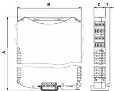
Housing height [A] : 114.5 mm
Housing depth [B]: 99 mm
Housing width [C]: 22.5 mm


natural_image
Pure electrical circuit lines without any symbolsDIN Power Connection (top)
5 N/C
4 N/C
3 N/C
2 POWER COMMON
1 DC POWER
Optional DIN Power Rail Connector Model 5M-PCON
2 TRANSDUCER CONNECTIONS
The Model 5M30 I/O CONNECTIONS are via non-removable screw terminals which will accept wire sizes from AWG 12 to 26. NOTE: The recommended transducer cabling would be eight wire, individually shielded, twisted pair - wired as indicated (Fig. 1) Sense lines must be connected at the transducer (as recommended) or at the 5M30 screw terminals - as a minimum. Table 2 denotes screw terminal assignments
Table 2 Model 5M30 Pin Assignments
| I/O Connector Conditioner | |||
| Pin Number | Screw Terminal | Terminal Label | Line Function |
| Top Rear 1 | 1 | + EXC | + EXCITATION |
| Top Rear 2 2 + SEN | + SENSE | ||
| Top Rear 3 | 3 | - EXC | - EXCITATION |
| Top Rear 4 | 4 | - SEN | - SENSE |
| Top Front 1 | 1 | + SIG | + SIGNAL Input |
| Top Front 2 | 2 | - SIG | -SIGNAL Input |
| Top Front 3 | 3 | CTR TAP | CENTER TAP (GRD) |
| Top Front 4 | 4 | SHIELD | |
| Bottom Front 1 | 1 | Ano Out | ANALOG Output |
| Bottom Front 2 | 2 | NUL | Null Control |
| Bottom Front 3 | 3 | NC | No Connection |
| Bottom Front 4 | 4 | SYC | SYNC - MASTER/SLAVE |
| Bottom Rear 1 | 1 | Acom | Analog Common |
| Bottom Rear 2 | 2 | Pcom | Power Common |
| Bottom Rear 3 | 3 | 24 V | 24 Vdc Power |
| Bottom Rear 4 | 4 | SHIELD | |
Fig. 1 Model 5M30 Transducer Cabling - AC LVDT

flowchart
graph TD
    A["PRIMARY COIL"] --> B["+SENSE"]
    A --> C["-SENSE"]
    A --> D["+EXCITATION"]
    A --> E["-EXCITATION"]
    B --> F["SIGNAL COMMON"]
    C --> F
    D --> F
    E --> F
    F --> G["SHIELD"]
    G --> H["Top Input Connectors (viewed from front)"]
    H --> I["Rear Terminals"]
    H --> J["Front Terminals"]
    G --> K["Bottom Power & Signal Connectors"]
    K --> L["Master/Slave to/from other modules"]
    L --> M["ANO Out 1 2 3 4 NUL NC SYC"]
    K --> N["Analog Common Power Common 24 Vdc Power Input"]
    K --> O["Front Terminals"]
    K --> P["Rear Terminals"]
    style A fill:#f9f,stroke:#333
    style K fill:#ccf,stroke:#333
Fig. 2 Model 5M30 Transducer Cabling Variable Reluctance
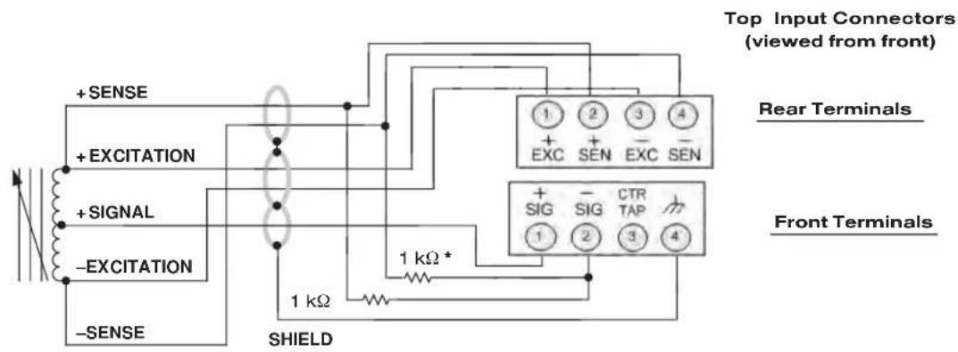
* User installed completion resistors
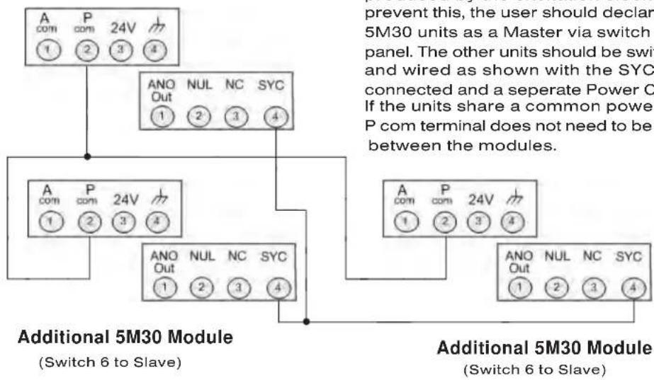
Master 5M30 Module (Switch 6 to Master)
flowchart
graph TD
    A["Additional 5M30 Module (Switch 6 to Slave)"] --> B["Prevent this, user should declare 5M30 units as a Master via switch panel. The other units should be switch and wired as shown with the SYC connected and a separate Power C. If the units share a common power P com terminal does not need to be between the modules."]
    A --> C["Additional 5M30 Module (Switch 6 to Slave)"]
    B --> D["Prevent this, user should declare 5M30 units as a Master via switch panel. The other units should be switch and wired as shown with the SYC connected and a separate Power C. If the units share a common power P com terminal does not need to be between the modules."]
    A --> E["Prevent this, user should declare 5M30 units as a Master via switch panel. The other units should be switch and wired as shown with the SYC connected and a separate Power C. If the units share a common power P com terminal does not need to be between the modules."]
    A --> F["Prevent this, user should declare 5M30 units as a Master via switch panel. The other units should be switch and wired as shown with the SYC connected and a separate Power C. If the units share a common power P com terminal does not need to be between the modules."]
Master / Slave Connections
When more than one 5M30 is being used in the same measurement setup, beat frequencies can be produced by the excitation clock oscillator. To prevent this, the user should declare one of the 5M30 units as a Master via switch 6 on the front panel. The other units should be switched to Slave and wired as shown with the SYC terminals connected and a separate Power Common wire. If the units share a common power supply, the P com terminal does not need to be connected between the modules.
Additional 5M30 Module (Switch 6 to Slave)
Fig. 3 Master / Slave Wiring
4. CALIBRATION
This section contains the instructions for calibrating the 5M30. Included is a functional description of the instrument front-panel (see Figure 3). To perform calibration, proceed as follows.
(a) Connect Power, Sensor and Analog terminals as required. Turn power ON. The front-panel indicator should light green to indicate the application of DC power. Allow 10 minutes of warmup for stabilization of transducer characteristics. Open the clear plastic front cover of the 5M30 unit.
(b) Set the Coarse Zero and Span controls to the default calibration position as indicated (<, MIN>)
(c) Position the front panel switches to the desired settings for the application. Refer to Figure 4 for details.
(d) If this is the system's first calibration, it is advised to jumper the terminal label "NUL" to "Power Common". This will defeat any conditioner zero and allow the user to reliably find the "Null" or electrical "Zero" position of the LVDT. With the jumper in place, mechanically adjust the LVDT or sensor to its most minimum analog output value. This will be mechanical Null.
(e) With mechanical Null established, remove the "NUL" to "Power Common" jumper. Adjust Coarse and Fine Zero for Zero Output. From the mechanical Null reference position, enable your span reference standard (gage block, micrometer, etc.). Adjust the Coarse Span control until you achieve a nominal full scale analog output value. If the 5M30 is in the Manual Phase Mode, adjust the Phase control to obtain the highest magnitude on the analog output. If the 5M30 is in "Auto" Phase mode, this is accomplished automatically. (Due to cable length and typically with long stroke LVDTs, the unit may require Manual Phase adjustment to achieve the desired precision). Once Phase has been accomplished, the 5M30 will not need to be re-phased for subsequent calibrations unless the cable or the transducer are replaced. Adjust Fine Span and Coarse Span, as needed, for the precise full scale analog output desired.
(f) Return the sensor to the "Zero" position (which may or may not be Null) and adjust the Coarse Zero and Fine Zero controls for the desired output. If the sensor requires additional Zero authority, place Switch 7 in the Extended position (100% offset) authority (see tech tip note). Normal setting is approx. 25% of span range.
(g) Re-apply the Full Scale condition stated in step (e). Adjust Coarse and Fine Span controls to achieve the desired output. Note that changes in Span will effect Zero. Span and Zero re-adjustments may need to be repeated to obtain the desired analog output value.
(h) For Negative Span adjustment, place the sensor in the opposite full scale position and adjust the Symmetry control for the desired output analog value.
(i) Once completed, replace the front plastic cover to the original position and ensure proper shielding and grounding have been done to the module and to the DIN rail used for mounting of the 5M30.
Null Calibration Check The instrument can be placed in the calibration mode by shorting "NUL" and Power Common terminals. This will defeat any zero function in the 5M30 to allow the user to establish a true "Null" or electrical zero position of the sensor. From this mechanical / electrical position, Full Scale positive and negative reference points can be obtained allowing the user the full linear operating range of the sensor and the 5M30 conditioner.
Master/Slave Connections. When more than one 5M30 is being used in a measurement setup (instruments are closely mounted or the transducer cabling is in a common conduit or raceway), beat frequencies may be produced from the 5-kHz oscillators used in the instruments to develop the excitation. To prevent beat frequencies from occurring, one unit can be designated the master, and the remaining units can be driven from the oscillator contained in the master unit. The remaining units are designated as slave instruments. To perform master/slave wiring, refer to Figure 3.
Phase & Signal Reversal: The manual phasing signal is derived from the excitation circuit. Therefore when doing signal reversal (typically positive displacement is a positive signal) must be accomplished by reversing the signal leads, not the excitation & sense leads from the transducer to the conditioner.

Switch 1 - Mode - selects current (I) or voltage analog output
Switch 2 - Volts - selects +/- 5 or +/- 10 Vdc when mode is voltage
Switch 3 - Current - selects 4-12-20 or 4-20mA when mode is current
Switch 4 - Filter - selects 1kHz or 100 Hz at 3 dB, for 100 Hz switch 5 must be set to the right
Switch 5 - Filter - selects 10 Hz or 100 Hz at 3 dB, for 100 Hz switch 4 must be set to the right
Switch 6 - Sync - selects excitaton clock to slave from a master module or to be master
Switch 7 - Zero Adj. - selects Extended (100%) or Normal (20%) zero authority
Switch 8 - Range - selects gain: Low (160-1600) or High (16 - 160) mV/V sensors
Switch 9 · Phase · selects Automatic or Manual Phase adjustment
Coarse Zero - 16 position switch adjustment for stepped zero balance control default calibration position indicated by "<"
Fine Zero - 18 turn potentiometer for fine zero balance control
Coarse Span · 16 position switch adjustment for stepped gain control default calibration position indicated by "MIN>"
Fine Span - 18 turn potentiometer for fine gain - span control
Symmetry - adjust the negative output span to be equal with the positive output
Phase - adjustment for phasing the AC modulated signal to its highest level at F.S.
Over Range - indicates when the analog output is 2% greater than mode selected
Power - indicates the power input voltage is ON
Fig. 4 Front Panel Settings and Indicators
Tech Tip on use of wide zero values for the 5M30 Conditioner (Switch 7)
If the large zero offset is used to correct for an offset within the transducer, no special calibration considerations need to be used beyond the normal two point calibration. If, however a large offset from the transducer's "native" zero is desired (e.g. -60% to +100% of the transducer mechanical range is to calibrate to 0 to 5 Volts output), the steps below can ease the process considerably. Note also that if the current output is chosen, then using the 4-12-20 ma choice effectively offsets -100% full scale.
(a) Choose the mechanical stimulation end points and calculate their difference in percent of the transducer's full scale range.
(b) Multiply the transducer's full scale electrical output by the value obtained in (a) and verify that it does not exceed the allowable signal range for the conditioner.
(c) Stimulate the transducer to mechanical zero and use the coarse and fine zero controls to achieve zero output from the conditioner.
(d) Stimulate the transducer to a mechanical value of one half of the value obtained in step (a) and use the coarse and fine span controls to set the conditioner output to one half of full scale.
(e) Repeat steps (c) and (d) as needed.
(f) Stimulate the transducer to the mechanical low end point and use the symmetry control to set the conditioner output to one half times the ratio of the percent of transducer full scale represented by the low end point and the value from step (a).
(g) Repeat steps (c), (d), and (f) as needed.
(h) Stimulate the transducer to the mechanical low end point again and use the coarse and fine zero controls to set the output to zero.
(i) Stimulate the transducer to the mechanical high end point and use the coarse and fine span controls to set the output to full scale.
(j) Repeat steps (h) and (i) as needed.
Example for +/- 100% of mechanical transducer range to cause zero to full scale output. Step (a) would be a value of 200% . Step (b), if the transducer outputs +/- 2 mV / V/ milli-inch and the stroke is +/- 100 milli-inches then 200% is 400 mV / V which is compatible on the low gain setting. Step (d) one half of that is 100% - set 100 milli-inch positive mechanical stimulation to one half full scale output. Step (f), the mechanical low end point is - 100 mill-inch and the ratio is -100% to +100% thus -1 times 1/2 = -50% or 2.5 Volts out on the 5 Vdc output range of the conditioner.
Example for -60% to +100% of mechanical transducer range to cause zero to full scale output. Step (a) would be a value of 160%. Step (b), if the transducer outputs +/- 2 mV/V/milli-inch and the stroke is +/- 50 milli-inches then 160% is 160 mV/V which is compatible on either gain setting. Step (d) one half of that is 80% - set -40 milli-inch positive mechanical stimulation to one half full scale output. Step (f), the mechanical low end point is -30 mill-inch and the ratio is -60% to +80% thus -60/80 = .75 times 1/2 = -37.5% or -1.875 Volts out on the 5 Vdc output range of the conditioner.
Product Warranty and Repair
Daytronic Corporation warrants its products to be free from defects in material and workmanship, under normal and proper use in accordance with our instructions, for the period of time specified below. Our liability under such warranty or in connection with any other claim relating to the products shall be limited to, at our option, the repair or replacement of any products or parts or components thereof which are returned to us freight prepaid and which are defective in material or workmanship or the refund of the purchase price to the Buyer.
ANY PRODUCT FOUND TO BE DAMAGED THROUGH CUSTOMER NEGLIGENCE OR MIS-USE MAY BE EXCLUDED FROM ANY AND ALL POLICIES CONTAINED IN THIS DOCUMENT.
ALL EQUIPMENT TO BE REPAIRED OR REPLACED UNDER WARRANTY MUST BE RETURNED TO THE FACTORY. Before returning a product or products for any reason, the customer must call Daytronic Customer Support Services at (937) 866-3300 to request a RETURN MATERIAL AUTHORIZATION (RMA). Once the customer has provided the necessary information and has been assigned a specific RMA, the product(s) in question may be returned to Daytronic by shipping it
Daytronic Corp., 1000 New Durham Road, Edison, New Jersey 08818
Daytronic Customer Service: 1-800-668-4745 service@daytronic.com
- Model 5M30 AC LVDT Module
- AC LVDT Phase Operation
- WARNING
- ADVERTENCIA
- Standard Accessories
- 5M30 SPECIFICATIONS
- Amplifier
- Step-Response Settling Time (Full-Scale Output @ 10 Hz)
- Dimensions
- TRANSDUCER CONNECTIONS
- Master / Slave Connections
- CALIBRATION
- Tech Tip on use of wide zero values for the 5M30 Conditioner (Switch 7)
- Product Warranty and Repair
Brand : Daytronic
Model : 5M30
Category : Detector