
Vive Mars CamTrack - Virtual reality headset HTC - Free user manual and instructions
Find the device manual for free Vive Mars CamTrack HTC in PDF.


| Product Type | Virtual reality headset |
| Brand | HTC |
| Model | Vive Mars CamTrack |
| Weight | Approximately 600 g |
| Dimensions (W x H x D) | 200 x 120 x 100 mm |
| Display Type | Dual AMOLED |
| Resolution | 2880 x 1600 (1440 x 1600 per eye) |
| Refresh Rate | 90 Hz |
| Field of View | 110 degrees |
| Tracking | Inside-out tracking with integrated cameras |
| Audio | Integrated headphones with 3D audio |
| Connectivity | USB 3.0, DisplayPort 1.4, Bluetooth 4.2 |
| Power Source | Rechargeable lithium-ion battery (optional) |
| Battery Life | Up to 2 hours (with battery pack) |
| Storage | microSD card slot (for apps and data) |
| Cleaning Instructions | Wipe lenses with a soft, dry microfiber cloth; clean body with a damp cloth. |
| Safety Precautions | Do not expose to liquids; stop use if discomfort occurs; keep away from children. |
| Spare Parts Availability | Face cushions, straps, and cables available from HTC. |
| Repairability | Modular design; user-replaceable face cushion and strap. |
| Compatible Systems | Windows 10/11, required VR-ready PC |
| Warranty | 1 year limited warranty |
Frequently Asked Questions - Vive Mars CamTrack HTC
User questions about Vive Mars CamTrack HTC
0 question about this device. Answer the ones you know or ask your own.
Ask a new question about this device
Download the instructions for your Virtual reality headset in PDF format for free! Find your manual Vive Mars CamTrack - HTC and take your electronic device back in hand. On this page are published all the documents necessary for the use of your device. Vive Mars CamTrack by HTC.
USER MANUAL Vive Mars CamTrack HTC
About VIVE Mars CamTrack 5 What's inside the box? 5
Hardware
SteamVR Base Station 2.0 8 VIVE Tracker (3.0) 9 Rover 9 Mars 10 Calibration kit 12
System setup
Setting up VIVE Mars CamTrack 13 Example virtual production studio setup 15 Connecting Mars to your PC 15 Mounting VIVE Tracker (3.0) to Rover 16 Connecting Rover to Mars 17 Setting up the base stations 18 Tips for setting up the base stations 19 Adding Mars as an endpoint in Unreal Engine 20 Enabling FreeD on Mars and adding Mars to Aximmetry 20 Manually updating the Mars firmware
Camera calibration
Setting up the calibration board 25
Collecting calibration data using the Camera Calibration Tool 26
Importing calibration data into Unreal Engine 29
Real-time compositing in Unreal Engine
Creating a project with a virtual production template 34
Connecting to Mars using the Live Link plug-in 36
Setting up the virtual camera using the Live Link Controller 37
Configuring the media source using Composure 40
FAQs
How many base stations can I use? 44
Can I use an odd number of base stations? 44
Cleaning the base stations 44
Can I use more than one VIVE Tracker (3.0)? 45
Why does VIVE Tracker (3.0) automatically turn off? 45
How do I verify that VIVE Tracker (3.0) is detected? 45
What does the status light on VIVE Tracker (3.0) mean? 45
Why doesn't the VIVE Tracker (3.0) status icon on the Mars dashboard turn blue? 45
Troubleshooting VIVE Tracker (3.0) 45
Why can't I see the incoming video feed in the Camera Calibration Tool? 45
Trademarks and copyrights
About this guide
The following symbols indicate useful and important information.

Notes provide details on setup, answers to common questions, and information on what to do in specific situations.

Tips provide supplemental information or alternative methods you may find helpful for particular steps or procedures.

Important notes provide information needed to complete certain tasks or configure specific settings or features.

Warnings provide critical information for avoiding potential problems or preventing damage to hardware.
Introduction
About VIVE Mars CamTrack
VIVE Mars CamTrack is a solution that integrates VIVE Tracker (3.0), SteamVR Base Station 2.0, and a suite of other devices and tools to help you incorporate VR tracking technology into your virtual production projects.
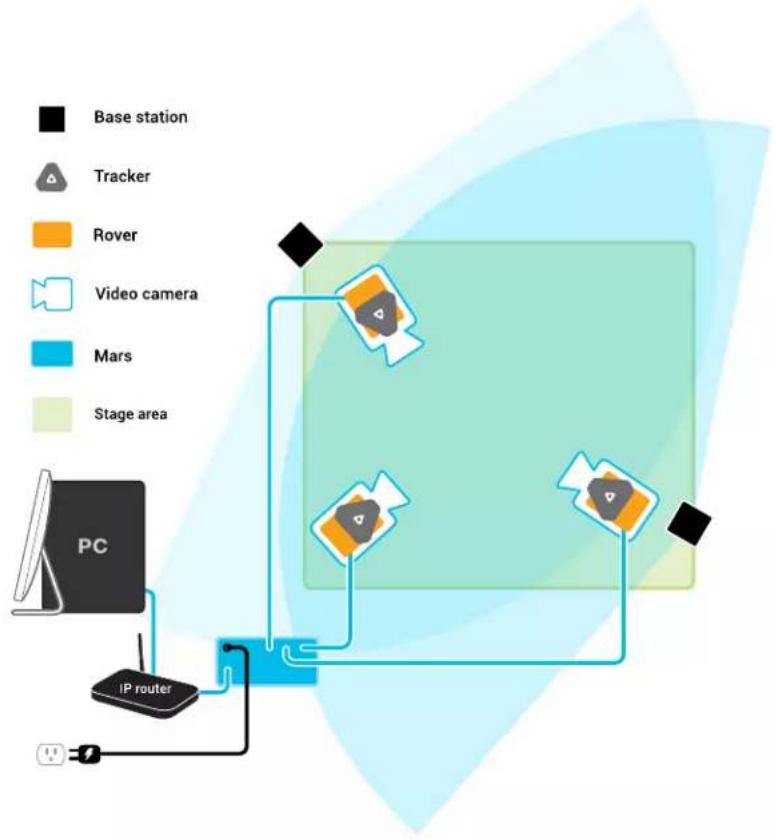
flowchart
graph TD
    A["Base station"] --> B["Tracker"]
    B --> C["Rover"]
    C --> D["Video camera"]
    D --> E["Mars"]
    E --> F["Stage area"]
    G["PC"] --> H["IP router"]
    H --> I["Central device"]
    style A fill:#000,stroke:#fff,color:#fff
    style G fill:#000,stroke:#fff,color:#fff
    style H fill:#000,stroke:#fff,color:#fff
    style I fill:#000,stroke:#fff,color:#fff
    subgraph Central Device
        J["Central Device 1"]
        K["Central Device 2"]
        L["Central Device 3"]
        M["Central Device 4"]
        N["Central Device 5"]
        O["Central Device 6"]
        P["Central Device 7"]
        Q["Central Device 8"]
        R["Central Device 9"]
        S["Central Device 10"]
    end
What's inside the box?
The packaging includes everything you'll need to set up your virtual production studio, as well as documentation to help you get started.
Here's what you'll find inside the box:
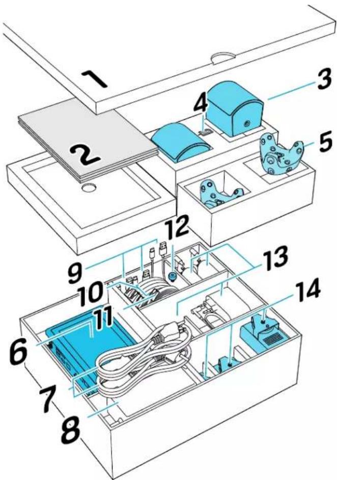
No. Item Quantity
1 Calibration kit 1
2 Documentation -
- Quick Start Guide 1
- Safety guide 1
- Warranty certificate 1
3 SteamVR Base Station 2.0 2
4 Channel changing pin (for base station) 1
5 VIVE Tracker (3.0) 2
6 Mars 1
7 Power cord for Mars* 1
8 AC adapter for Mars 1
9 USB cable (VIVE Tracker (3.0) to Rover) 3
10 15-m LAN cable (Mars to Rover)
3
No. Item Quantity
11 5-m LAN cable (Mars to router) 1
12 Screw for calibration board 1
13 AC adapter for base station* 2
14 Rover** 3
*Items may vary according to country or region.
**A third VIVE Tracker (3.0) must be purchased separately.
If you have questions or concerns about VIVE Mars CamTrack, or if you want to report damaged or missing items, go to vive.com/support/contactus to contact the VIVE Support team.
Hardware
SteamVR Base Station 2.0
SteamVR Base Station 2.0 uses advanced optics to determine the exact location of each VIVE Tracker (3.0) and Rover module.

- The base stations transmit signals to VIVE Tracker (3.0). Make sure the lines of sight between the base stations and the VIVE Tracker (3.0) units are not obstructed.
- The signals transmitted by the base stations may interfere with nearby infrared sensors, including those used by infrared remote controls.
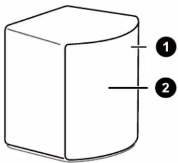
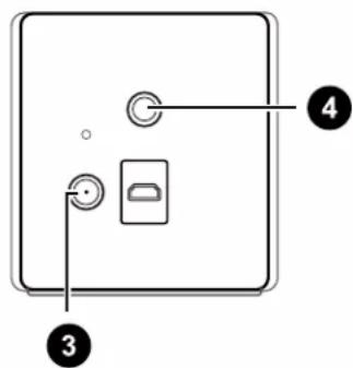
1 Status light
2 Front panel
3 Power port
4 Threaded mounting hole

- Do not attempt to force open the base stations for any reason. Doing so could injure you or damage the product.
- If the front panel of a base station is cracked or damaged, stop using the base station immediately and contact the VIVE Support team.
VIVE Tracker (3.0)
VIVE Tracker (3.0) sends location data to the Rover module it's attached to.
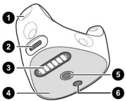
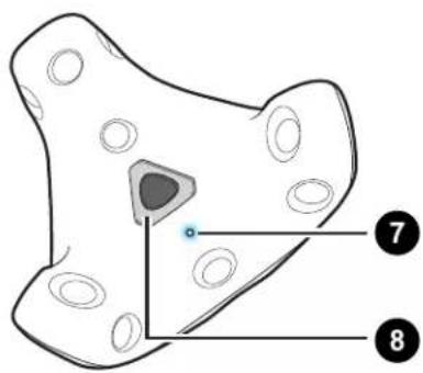
1 Sensors
2 USB Type-C ^® port
3 Pogo pin port
4 Friction pad
5 Standard camera mount
6 Stabilizing pin recess
7 Status light
8 Power button
Visit VIVE Support to learn more about VIVE Tracker (3.0).
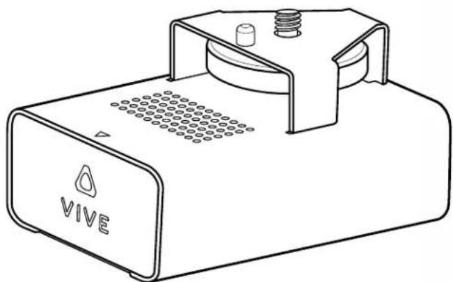
Rover
Rover sends tracking data from VIVE Tracker (3.0) to Mars.
Rover collects tracking data from VIVE Tracker (3.0) and relays it to Mars to refresh the signal and prevent signal degradation.
natural_image
Line drawing of a VIVE electronic device with ports and a central button (no text or symbols on the device itself)Rover is also responsible for transmitting FIZ (focus, iris, zoom) data that the lens encoder can convert into data that can be used by virtual production engines. VIVE Mars CamTrack supports the LOLED Indiemark lens encoder.
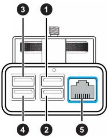
1 USB Type-A port 1 Primary connection port for VIVE Tracker (3.0)
2 USB Type-A port 2 Zoom data can be transmitted through this port
3 USB Type-A port 3 Focus data can be transmitted through this port
4 USB Type-A port 4 Iris data can be transmitted through this port
5 Ethernet port For connecting Rover to Mars to transmit tracking data
Mars
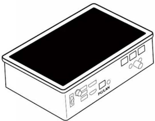
Mars collects tracking data from each Rover and sends it to your PC through an IP router.
Mars allows you to manage each connected device and check relevant information through the Mars dashboard, which is located directly on the top side of Mars.
natural_image
Line drawing of a rectangular electronic device with a black top panel and control buttons (no text or symbols)11 Hardware
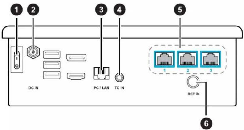
1 Power switch For powering Mars on and off
2 DC power input For connecting Mars to power
3 PC/LAN port For connecting to IP router
4 TC input For connecting timecode generator
5 Ethernet ports For connecting Rover units
6 REF input For connecting genlock generator
Mars dashboard
The Mars dashboard displays the connection status of each connected hardware device and other system-related information. You can also access several system configuration options.
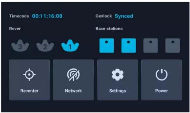
- Rover: The status of each Rover module is represented by a VIVE Tracker (3.0) icon.
| Icon | Device status |
| Solid gray No Rover module is detected. | |
| Flashing gray The Rover module is booting up. | |
| Flashing blue VIVE Tracker (3.0) is detected but not tracking yet. | |
Icon Device status
Solid blue VIVE Tracker (3.0) is detected and tracking.
- Timecode: Displays the timecode from a connected camera or sync generator.
- Genlock: The status Synced will be displayed when an external sync generator is connected.

An external sync generator is required to use this feature.
- Base stations: Displays the connection status of each base station.
- Recenter: Reset the coordinates of a tracker to a positional origin (neutral coordinates).
- Network: Displays the IP address when the network status is active. Tap to configure network settings.
■ Power: Tap to restart or power off Mars. - Settings: Configure additional settings and check for system updates. You can also export system logs for system diagnostics and analysis.
Calibration kit
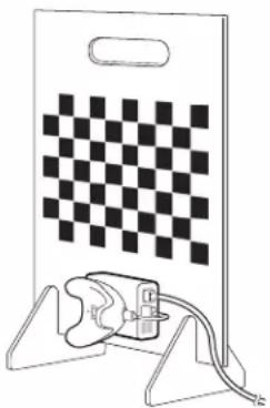
The calibration kit includes items for assembling the calibration board, which is placed inside the tracking area during the camera calibration process.
natural_image
Diagram of a checkerboard-themed device with a plug and cable, no text or symbols presentThe calibration kit includes an acrylic calibration board with a chessboard pattern, which is used as the calibration target during camera calibration. The kit also includes base supports for the board and a screw for attaching a Rover module and VIVE Tracker (3.0), which is used to determine the location of the calibration target.
After setting up VIVE Mars CamTrack, you'll need to assemble the calibration board and attach a Rover module and VIVE Tracker (3.0) to it. You can then place the board inside the tracking area and start the calibration process. For details, see Setting up the calibration board on page 25 and Collecting calibration data using the Camera Calibration Tool on page 26.
System setup
Setting up VIVE Mars CamTrack
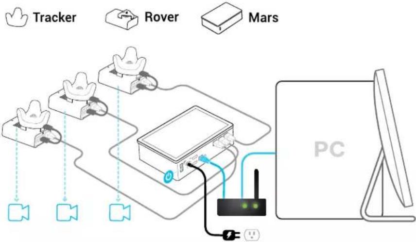
In addition to the included hardware components, you'll need an IP router and a PC equipped with a virtual production engine.
flowchart
graph TD
    A["Tracker"] --> B["Rover"]
    B --> C["Mars"]
    D["Computer PC"] --> E["Switch"]
    E --> F["Video Signal"]
    style A fill:#f9f,stroke:#333
    style B fill:#ccf,stroke:#333
    style C fill:#cfc,stroke:#333
    style D fill:#fcc,stroke:#333
    style E fill:#ffc,stroke:#333
    style F fill:#cff,stroke:#333
- Connect Mars to your PC using an IP router.
See Connecting Mars to your PC on page 15.
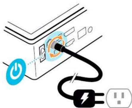
- Connect Mars to a power outlet using the included AC adapter and power cord.
-
Power on Mars.
-
Mount VIVE Tracker (3.0) to Rover.
See Mounting VIVE Tracker (3.0) to Rover on page 16.
- Connect Rover to Mars. Rover will turn on automatically.
See Connecting Rover to Mars on page 17.
- Check the Mars dashboard to confirm that Rover is detected.
See Mars on page 10 for details on the Mars dashboard.

Even if the status light on VIVE Tracker (3.0) isn't green, it can still be tracked. Just check the status icon on the Mars dashboard to confirm the tracking status.
See What does the status light on VIVE Tracker (3.0) mean? on page 45 for details.
- Set up the base stations, but do not connect them all to power at the same time. See Setting up the base stations on page 18.
- Connect Mars to your virtual production software. See Adding Mars as an endpoint in Unreal Engine on page 20.
- Set up the calibration board and start collecting calibration data. See Setting up the calibration board on page 25 and Collecting calibration data using the Camera Calibration Tool on page 26.
15 System setup
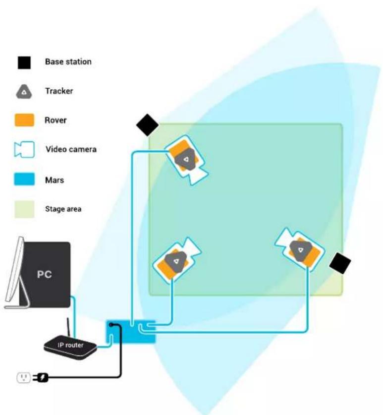
Example virtual production studio setup
You can mount Rover to any type of camera mounting accessory that uses a 1/4-inch screw.
flowchart
graph TD
    A["Base station"] --> B["Tracker"]
    B --> C["Rover"]
    C --> D["Video camera"]
    D --> E["Mars"]
    E --> F["Stage area"]
    G["PC"] --> H["IP router"]
    H --> I["Wireless cable"]
    style A fill:#000,stroke:#fff,color:#fff
    style G fill:#000,stroke:#fff,color:#fff
    style H fill:#000,stroke:#fff,color:#fff
    style I fill:#000,stroke:#fff,color:#fff
    style_J["Satellite"] --> K["Satellite device"]
    style_L["Satellite device"] --> M["Satellite device with monitor"]
    style_N["Satellite device"] --> O["Satellite device with monitor"]
Connecting Mars to your PC
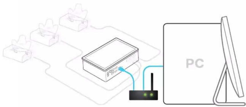
Mars processes positioning data and sends it to your PC through an IP router.
- Connect one end of the 5-m LAN cable to the Ethernet port (labeled PC/LAN) on Mars.
- Connect the other end of the 5-m LAN cable to an Ethernet port on your router.
16 System setup
Mounting VIVE Tracker (3.0) to Rover
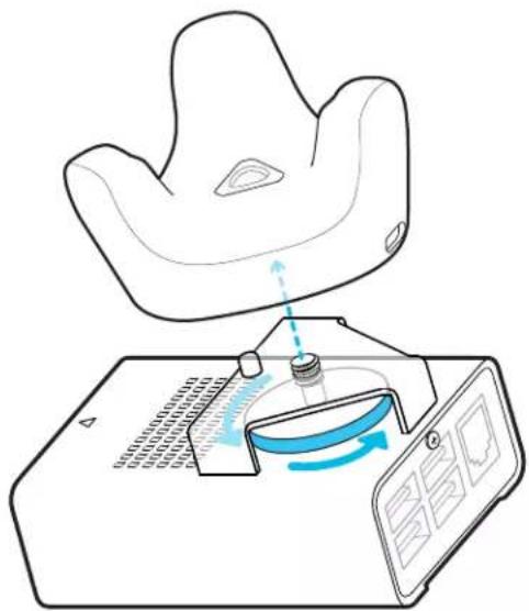
Rover comes installed with a mounting plate for mounting VIVE Tracker (3.0) to Rover.
-
Align the mounting screw on Rover with the screw hole on the bottom of VIVE Tracker (3.0).
-
Attach VIVE Tracker (3.0) to Rover and rotate the mounting screw counterclockwise until it is securely fastened.
natural_image
Illustration of a medical procedure on a patient's backrest, showing a syringe inserted into a patient's seat with a monitor displaying a blue spiral (no text or symbols present)
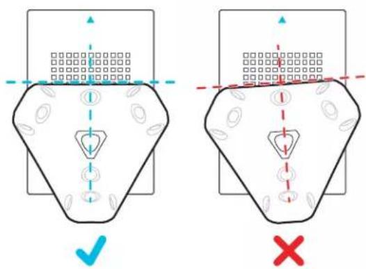
Make sure the front edge of the tracker is parallel to the front side of Rover, which is indicated by the blue arrow on the chassis. Failure to properly align the tracker may reduce the accuracy of camera calibration.
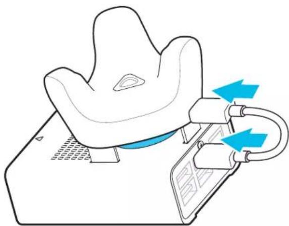
- Connect the Type-C end of a 10-cm USB Type-C to Type-A cable to the USB Type-C port on VIVE Tracker (3.0), and then connect the Type-A end to a USB Type-A port on Rover.
17 System setup
natural_image
Illustration of a medical device with blue arrows indicating pressure or movement (no text or symbols present)Connecting Rover to Mars
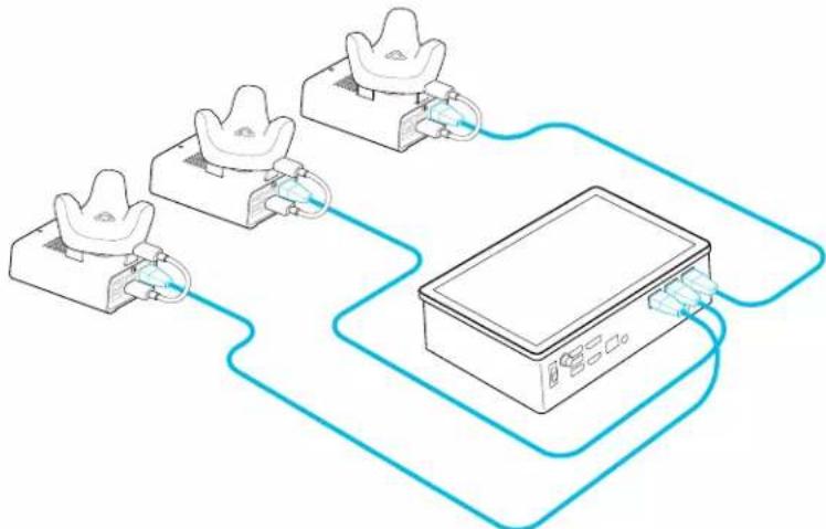
You can connect up to three assembled Rover modules to Mars at the same time.
!
Only two assembled Rover modules can be connected to Mars during camera calibration—one for your camera, and one for the calibration board.
- Connect one end of a 15-m LAN cable to the Ethernet port on Rover.
- Connect the other end of the 15-m LAN cable to an Ethernet port on Mars.
flowchart
graph TD
    A["Gold ingots"] --> B["Device"]
    C["Gold ingots"] --> B
    D["Gold ingots"] --> B
    E["Gold ingots"] --> B
    B --> F["Output"]
    style B fill:#f9f,stroke:#333
!
Do not connect any third-party devices to Mars using these Ethernet ports. Doing so will void the warranty and may cause damage to Mars and any connected third-party devices.
Setting up the base stations
Here's how to set up the base stations for VIVE Mars CamTrack.
- Mount the base stations at the edge of the tracking area near power outlets.

If you're not able to mount the base stations using the mounting kit, you can attach them to tripods or place them on a stable surface, as long as it's high enough.
For details on using the mounting kit, visit VIVE Support.
- Face each base station toward the center of the tracking area where you plan to set up the calibration board. See Collecting calibration data using the Camera Calibration Tool on page 26 for details.

Remember to peel the protective film off the front panels of the base stations.
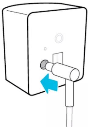
- Connect the base stations to power one at a time. Make sure the first base station is detected by Mars before connecting the second one.
natural_image
Diagram of a water dispenser with a blue arrow indicating left-hand valve (no text or symbols present)
Only use the power cables and adapters included with the base stations.
Depending on the hardware version of your base stations, the LED indicators will be white or green.

If Mars doesn't automatically detect the base stations, press the channel button on the back with the channel changing pin to set the channel manually. You may need to set the channel manually for any additional base stations you connect.
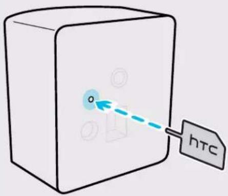
The status icon on the Mars dashboard will turn blue about 10-15 seconds after setting the base station channel.
Tips for setting up the base stations
Before setting up the base stations, make sure to prepare your production area based on the amount of space you have available.
The minimum area required for room-scale setup is 2 m x 1.5 m (6.5 ft x 5 ft).
Set up your base stations to fit the requirements of your studio space. For the best results, keep the following things in mind:
- Make sure the base stations are set up outside the production area and adequately secured to avoid damage or compromised performance.
- Each base station has a 150-degree horizontal field of view and a 110-degree vertical field of view. To maximize the scope of your production area, set up the base stations at least 2 m (6.5 ft) high and 5 m (16 ft) apart. In addition, make sure each base station is tilted down between 30 and 45 degrees.
- For optimal tracking, make sure VIVE Tracker (3.0) is at least 0.5 m (1.6 ft) away from each base station and that each base station is at least 0.5 m (1.6 ft) high. The height of the base stations determines how far up or down they need to be tilted to fully cover the production area.
- Avoid setting up the base stations under bright lights, which could negatively affect their tracking performance.
- After turning on the base stations, do not move or tilt them, as doing so could disrupt tracking. If you reposition the base stations, you'll need to set them up again.
Adding Mars as an endpoint in Unreal Engine
Before starting camera calibration, you'll need to add Mars as an endpoint in Unreal™ Engine.
-
Go to Edit > Project Settings > Plugins > UDP Messaging > Static Endpoints, and then click the + button.
-
Enter the Mars IP address and port number (in this example, "6666").
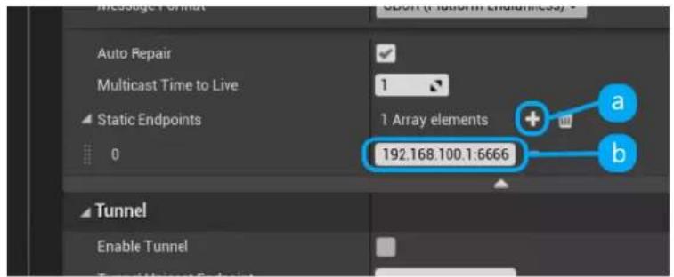

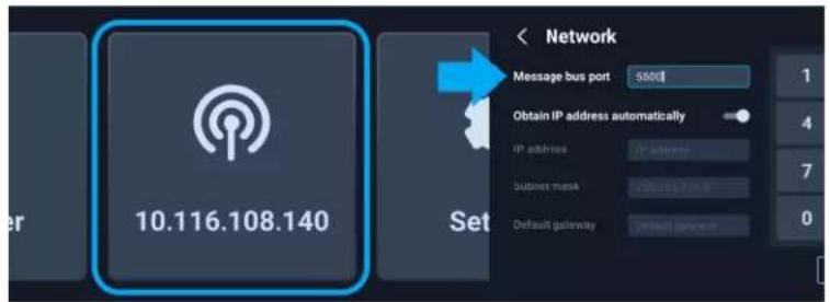
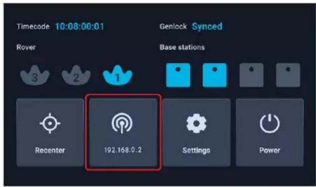
You can find the Mars IP on the Mars dashboard and the port number in the network settings. Just tap the network button to open the network settings.
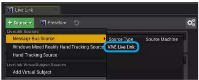
- Click + Source, go to Message Bus Source under Live Link Sources, and then click VIVE Live Link to open the Live Link plug-in.
Enabling FreeD on Mars and adding Mars to Aximmetry
FreeD is an industry-standard protocol used by cameras to directly send tracking data—such as transform, rotation, focus, and zoom—to virtual production systems. It allows production systems to incorporate realistic virtual studio sets into video productions without the need for additional hardware.
Here's how to enable FreeD on Mars and add Mars to Aximmetry:
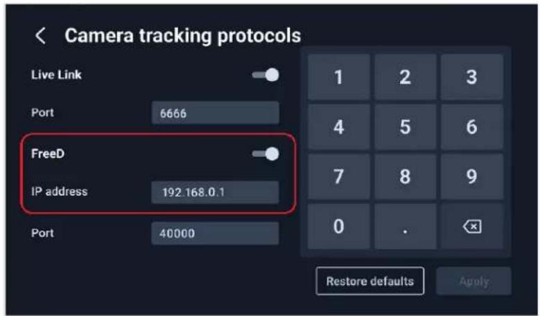
- On the Mars dashboard, tap Settings and check your firmware version. Make sure you have Mars firmware 2.03.999.1 or later installed.
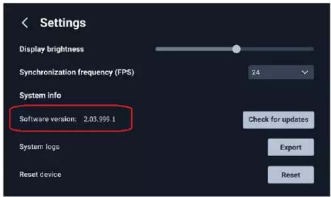
For details on how to update the firmware, see Manually updating the Mars firmware on page 23.
- On the Mars dashboard, tap Network (or tap the Mars IP when the network is active), and then tap Camera tracking protocols.
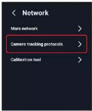
- Turn on FreeD and enter your computer's IP address.
22 System setup
-
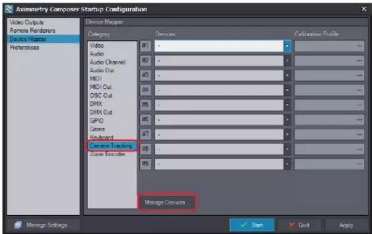
On your computer, launch Aximmetry. The Startup Configuration window will be displayed.
-
Click Device Mapper in the left pane.
-
Under Category, select Camera Tracking, and then click Manage Devices.
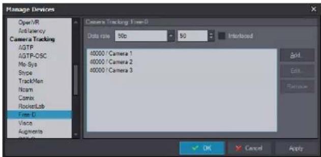
- In the Manage Devices dialog box, select Free-D under Camera Tracking, and then click Add.
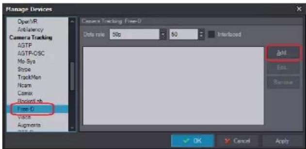
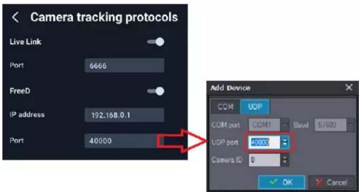
The Add Device dialog box will be displayed.
- In the UDP port field, enter the port number that appears under FreeD on the Camera tracking protocols screen on the Mars dashboard.
23 System setup
-
In the Camera ID field, select 1 to associate it with Rover 1's Ethernet port on Mars, and then click OK.
-
Repeat steps 7 to 9 to add Rover 2 and Rover 3. In the Camera ID field, select 2 and 3 respectively.
Manually updating the Mars firmware
Mars regularly checks for updates automatically. You can also update the firmware manually to get the latest features and enhancements.
- Download the Mars firmware.
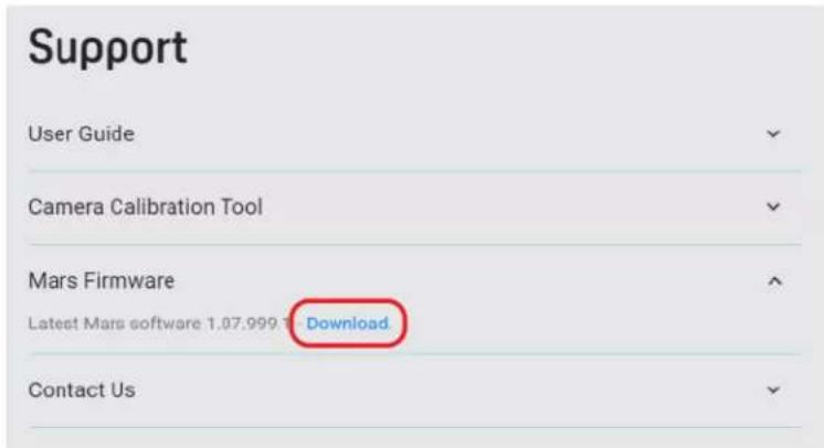
a) Go to https://mars.vive.com/.
b) Scroll down to the bottom of the page to find the Support section.
c) Click the Mars Firmware dropdown heading, and then click Download.
- Copy the firmware update package to a USB Type-A flash drive.
24 System setup
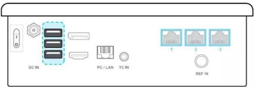
- Connect the flash drive to one of the three USB Type-A ports on the back of Mars.
- On the Mars dashboard, tap Settings, and then tap Check for updates.
For details on the Mars dashboard, see Mars on page 10.
- Follow the onscreen instructions to install the firmware update package.
Camera calibration
Setting up the calibration board
Set up the calibration board and place it inside the tracking area on your set before starting the camera calibration process.
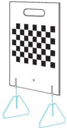
- Attach the base supports to the calibration board.
natural_image
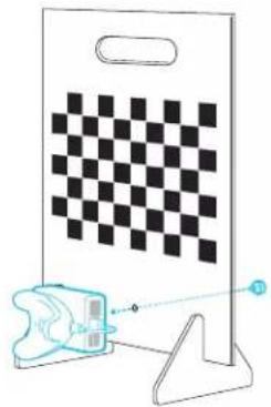
Illustration of a door with a checkerboard pattern and two triangular hoods hanging below (no text or symbols)- Attach an assembled Rover module to the calibration board under the chessboard pattern using the screw included in the box.
natural_image
Diagram showing a checkerboard pattern on a document and a stylized object with a pointer, no text or symbols present.
- Make sure the Rover module is securely attached to the calibration board. Any gaps between the board and the module could affect calibration.
-
The in-box screw has an interior screw thread so you can install the Rover module and calibration board to a tripod for greater precision during calibration.
-
Place the calibration board inside the tracking area at the same height as the camera, with the camera facing the board at a 90-degree angle.
See Example virtual production studio setup on page 15 for details.

Make sure the calibration board doesn't obscure the Rover module from the base stations after rotating it 45 degrees in either direction. This will be important during camera calibration.
See Collecting calibration data using the Camera Calibration Tool on page 26 for details.
Collecting calibration data using the Camera Calibration Tool
The Camera Calibration Tool captures images to generate calibration data that you can import into your virtual production engine to calibrate your camera.
If you haven't downloaded the Camera Calibration Tool, visit www.vive.com/mars/cct.
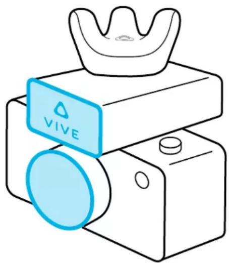
- Attach a Rover module to your camera, with the front side of Rover parallel to the camera lens.
natural_image
Line drawing of a VIVE smartphone with a gold crown and blue lens (no text or symbols on the device itself)
The internal screw thread on the bottom of Rover has a depth of 5.5 mm. To avoid damaging Rover or your camera during installation, make sure the exterior screw thread on your camera is no longer than 4.5 mm.
- On your PC, open the Camera Calibration Tool, enter the Mars IP and port number, and then click Connect.


You can find the Mars IP on the Mars dashboard. See Mars on page 10 for details.
- Select your video capture device from the Video source dropdown menu.
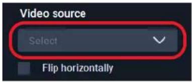

If the video feed is inverted on the x-axis, you can select Flip horizontally to correct it.
- For Save location, click the folder icon and select a destination folder for the images and calibration data.
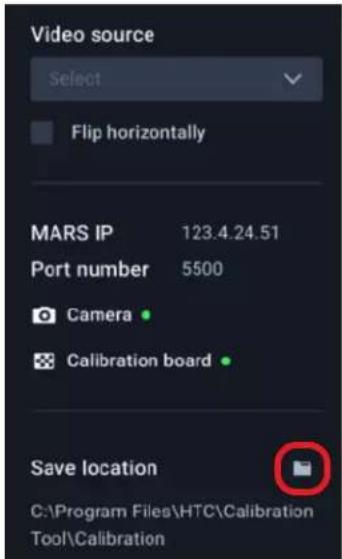
- Click the play button to start the calibration process.
- Move the camera so the chessboard pattern falls inside the red frame.
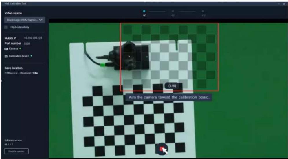
The frame will turn blue, and the Camera Calibration Tool will capture an image.
-
Move the camera as needed to capture additional images until you're prompted to rotate the calibration board.
-
Rotate the calibration board 45 degrees (counterclockwise), then click Continue and capture a second set of images.
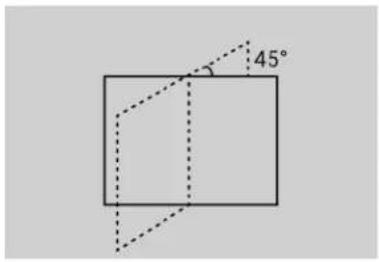
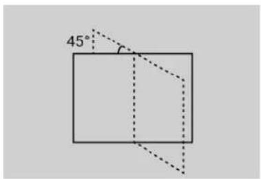
After capturing the second set of images, you'll be prompted to rotate the board 45 degrees in the opposite direction.
- Rotate the calibration board 45 degrees clockwise (-45 degrees), click Continue, and then capture the third and final set of images.
The Camera Calibration Tool will process the images and display the results. Click Show in folder to open the save location containing the images and calibration data.
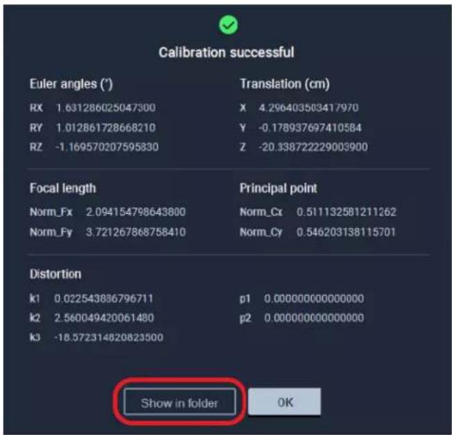
- Import the calibration data into your virtual production engine to calibrate your camera.
For details, see Importing calibration data into Unreal Engine on page 29.
Importing calibration data into Unreal Engine
Here's how to configure the virtual camera with the calibration data collected using the Camera Calibration Tool.
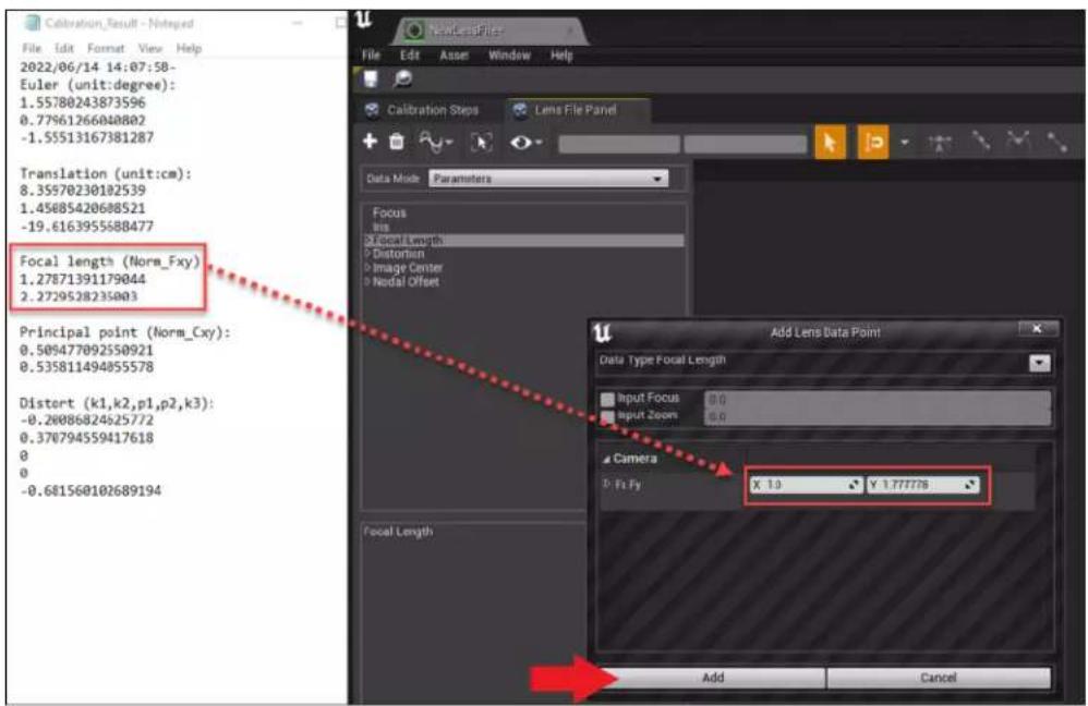
- Open the TXT file containing the calibration data.
a) Open the save location and find Calibration_Result.txt.
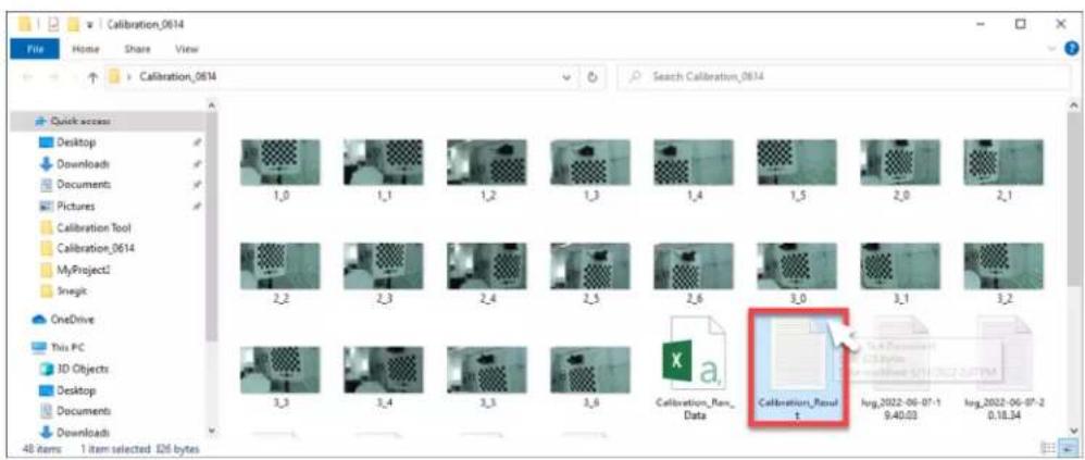
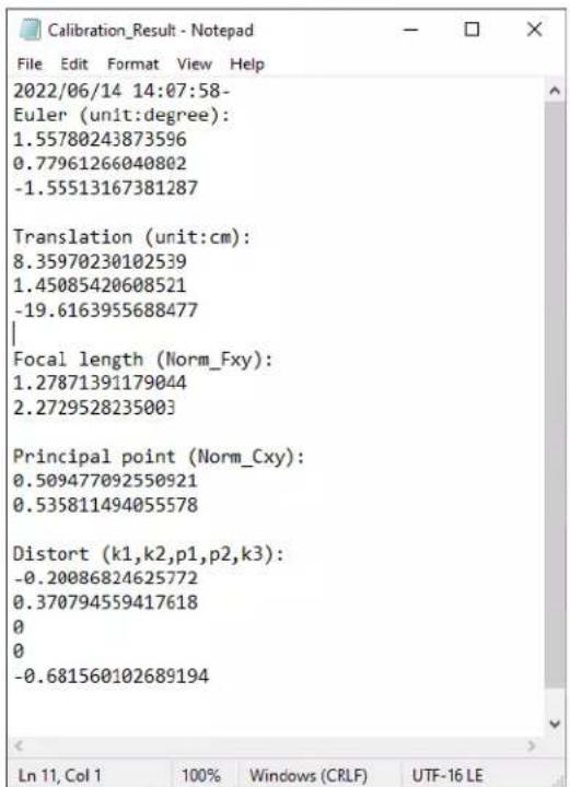
b) Double-click the file to open it and view the calibration data. Keep the file open for reference.
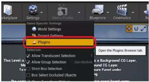
- In Unreal Engine, enable the Camera Calibration plug-in.
a) Click Settings > Plugins to open the Plugins browser tab.
b) Search for camera calibration and then select Enabled under the Camera Calibration plug-in.
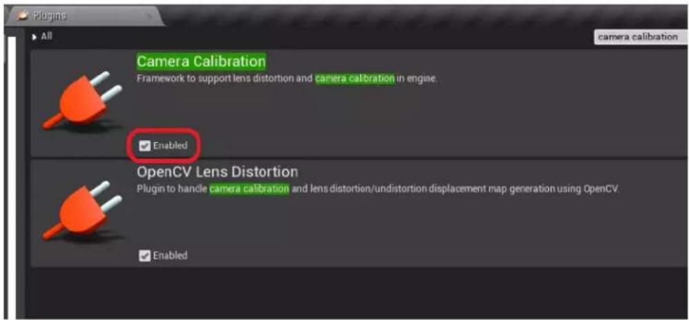
Restart Unreal Engine when prompted.
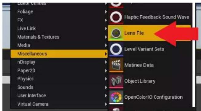
- Right-click inside the Content Browser panel to open the context menu, then go to Miscellaneous and click Lens File to create a Lens File asset.
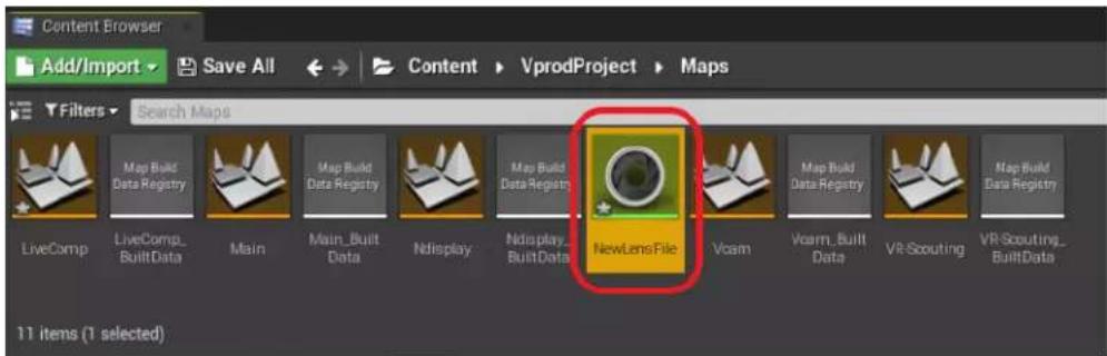
- In the Content Browser panel, double-click the Lens File asset to open the Lens File Asset Editor.
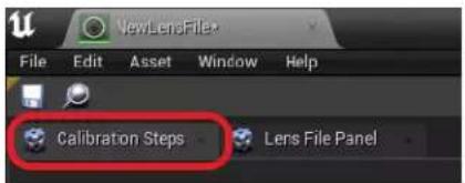
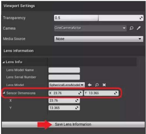
- Click the Calibration Steps panel and specify the Sensor Dimensions for your camera, then click Save Lens Information.
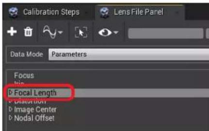
- Click the Lens File Panel and select Focal Length.
- Click the + button to open the Add Lens Data Point window, then enter the focal length values (Fx, Fy) from Calibration_Result.txt and click Add.
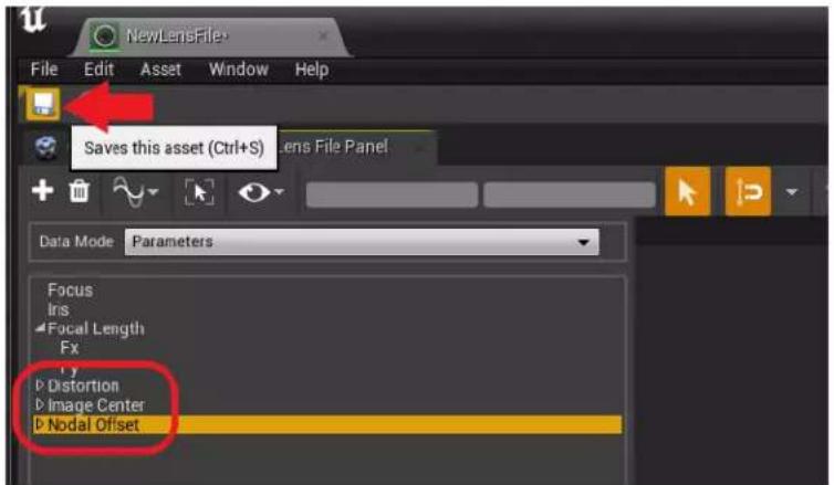
- Do the same for Distortion, Image Center, and Nodal Offset, and then click the Save button.
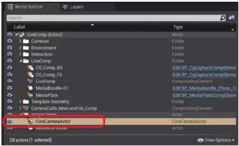
9. In the World Outliner panel, select your CineCameraActor.
10. Go to the Details panel and select LiveLinkComponent Controller. Select Live Link Camera Controller as the Camera Role and then select your Lens File.
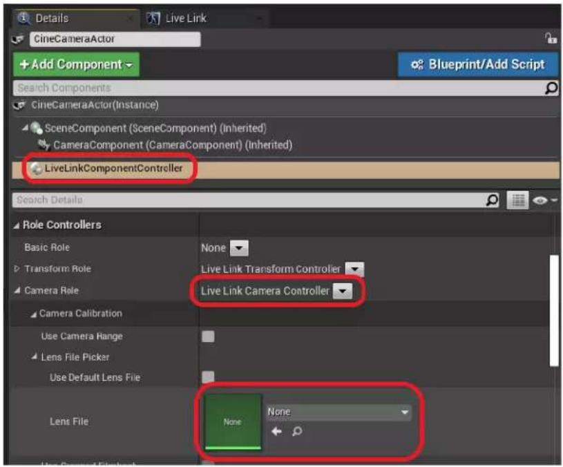
You can also drag and drop the Lens File asset from the Content Browser panel.
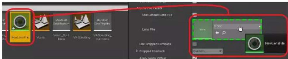
The calibration data will now be applied to the virtual camera.
Real-time compositing in Unreal Engine
Creating a project with a virtual production template
Create a project with a virtual production template to utilize virtual production components.
- Launch Unreal Engine on your computer. The Unreal Project Browser will appear.
- Select the category Film, Television, and Live Events.
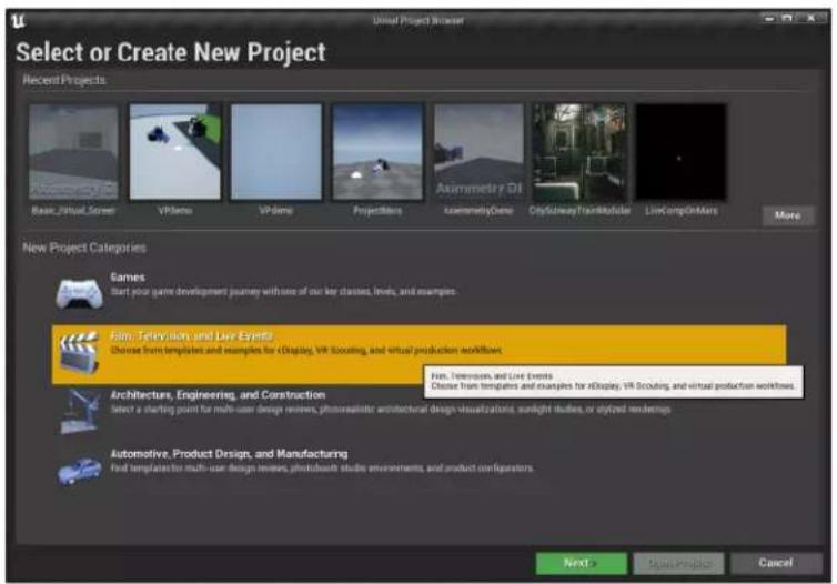
- Select the template Virtual Production.
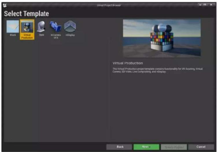
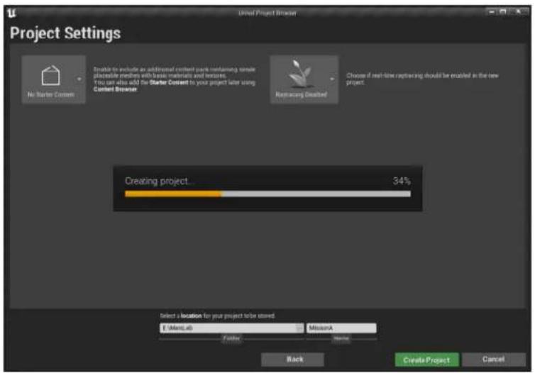
- On the Project Settings screen, select a destination folder for the project, and then click Create Project.
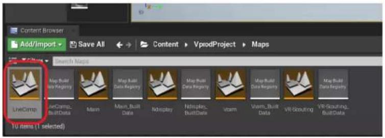
- In the Content Browser panel, go to Content > VprodProject > Maps and open LiveComp.
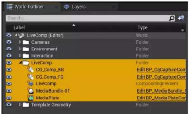
The LiveComp folder will appear in the World Outliner panel.
Connecting to Mars using the Live Link plug-in
After creating a project, you'll need to add Mars using the Live Link plug-in.
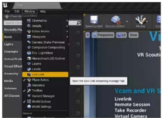
- Open Live Link from the Window menu.
- In the Live Link tab, click + Source, then go to Message Bus Source and select the Mars source type.
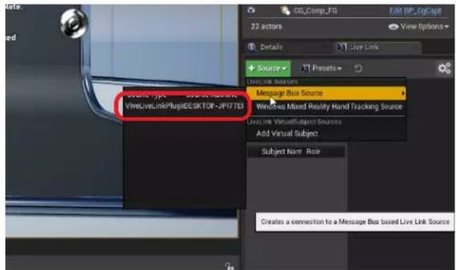
If Mars doesn't appear as an endpoint under Message Bus Source, you'll need to add it manually. See Adding Mars as an endpoint in Unreal Engine on page 20.
The Rover units connected to Mars will appear under Subject Name in the Live Link panel.
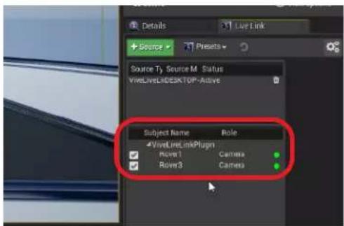
Setting up the virtual camera using the Live Link Controller
Here's how to set up your virtual camera in an Unreal Engine virtual production project.
- In the Place Actors panel, go to the Basic tab, and then click and drag Empty Actor into your viewport to add it to your scene.
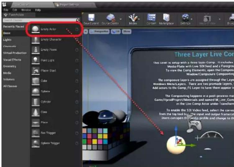
- In the World Outliner panel, rename the empty actor to Stage Center.
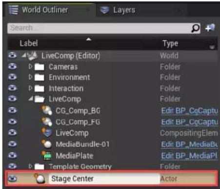
- Set the Location and Rotation coordinates of the Stage Center actor to 0.
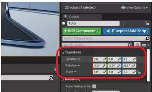
- Pull the Stage Center actor up through the floor of the viewport so it's fully visible.
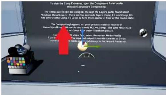
-
In the World Outliner panel, drag the Cine Camera Actor under the Stage Center actor, and then set its Location and Rotation coordinates to 0.
-
In the World Outliner panel, select CineCameraActor.
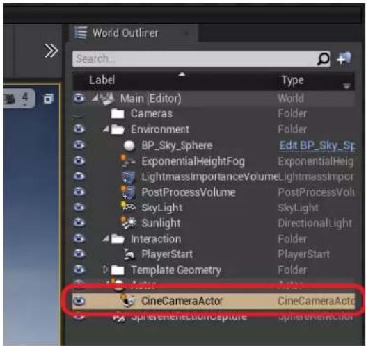
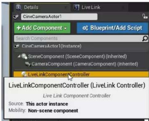
- In the Details panel, click Add Component, and then select Live Link Controller.
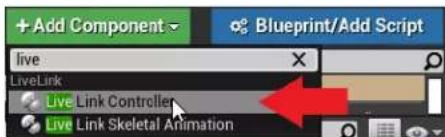
- Select LiveLinkComponentController.
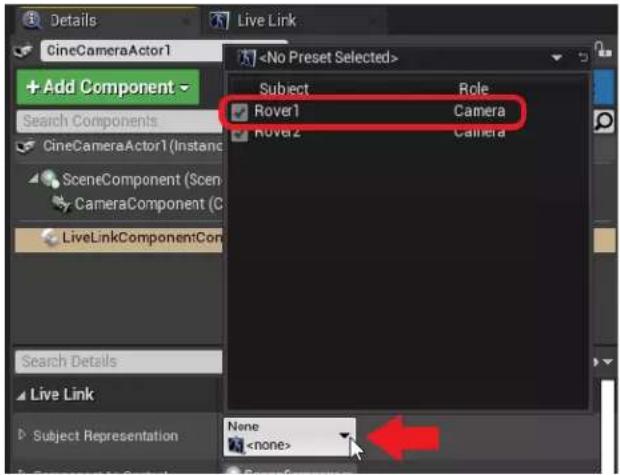
9. For Subject Representation, select Rover 1.
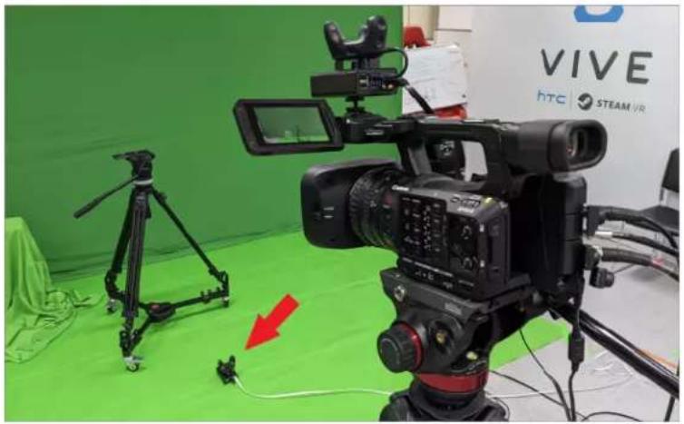
- Place a Rover unit on your set in a stage center position with the VIVE logo facing away from the camera. Connect it to Mars, and then tap Recenter on the Mars dashboard.
natural_image
Studio setup featuring a VIVE HTC and STEAM VR camera on a green screen, with a tripod-mounted device nearby (no visible text or symbols on main subject)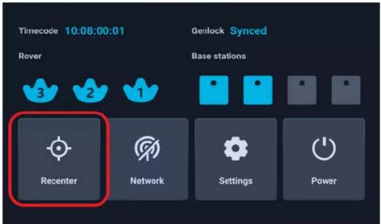
The Location and Rotation coordinates of Rover 2 will be set to 0 and the actor CineCameraActor (Rover 1) will stay in the same relative position.
Configuring the media source using Composure
Here's how to configure the media source using Composure, the standard graphics utility plug-in for Unreal Engine.
1. In the World Outliner panel, select MediaBundle-01.
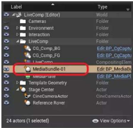
2. In the Details panel, double-click the icon under Media Bundle to open the configuration panel.
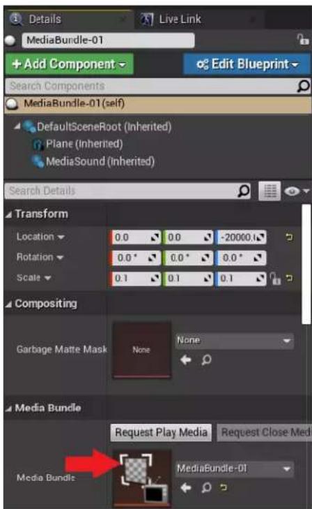
- For Media Source, select the media source associated with your video capture card. Make sure the settings are consistent with your camera's outgoing video feed.
![Media Bundle Media Source Blackmagic Media Source [In] - DeckLink 8K Pro (1) [Innote1/1080y2087] Name Device ● DeckLink 8K Pro (1) ● DeckLink 8K Pro (2) Resolution ● HD 739 ● HD 1080 ● 2K DCI ● 4K UHD ● 4K DCI Standard ■ Progressive ■ Interlaced Frame Rate ■ 23.976 fps ■ 24 fps ■ 23 fps ■ 29.97 fps ■ 30 fps ■ 47.982 fps ■ 48 fps Apply](/content/2026/05/1011389/images/54ce791193175228774142fbe5cd6e620b18136e11b12a6ed17e859149c518ea.jpg)
Remember to click Apply if you change any settings.
- Make sure Is SRGBInput is selected, and then click Save.
![Configuration Timecode Format Audio Video Capture Video Color Format Is SRGBInput Max Num Video Frame Buffer Debug Synchronization Loop Media Source Reopen Source on Error [In] - DeckLink 8K Pro (1) [device1/10B0p2997] LTC 8bit YUV True](/content/2026/05/1011389/images/bfb3e1dff3d2303b25ccd57f3a40dd5f0e5a8a805949d7ab344901646e2479b4.jpg)
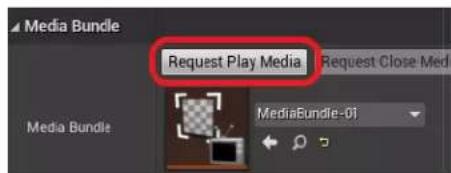
- In the Details panel, click the Request Play Media button under Media Bundle.
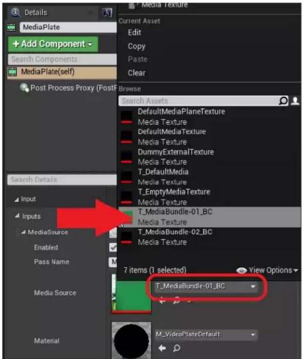
- In the World Outliner panel, select MediaPlate, and then select the texture T_MediaBundle-01_BC as the Media Source in the Details panel.
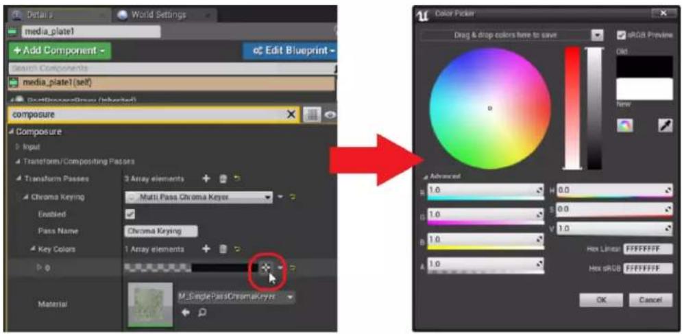
- Go to Transform Passes > Chroma Keying > Key Colors, click the + button to add a key color element, and then click the picker button to open the Color Picker.
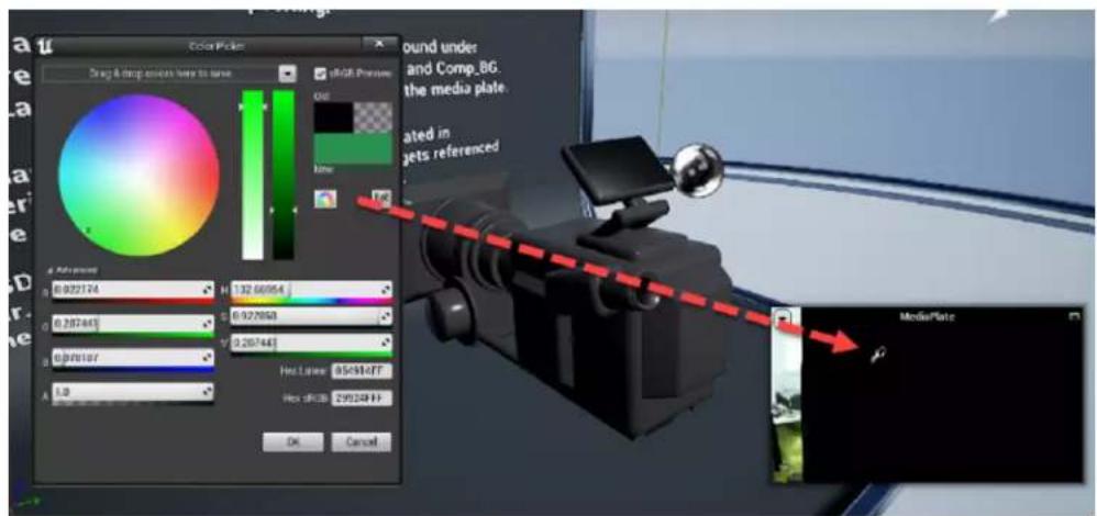
- Select the correct green value, then use the Eye Dropper to add it to the MediaPlate preview.
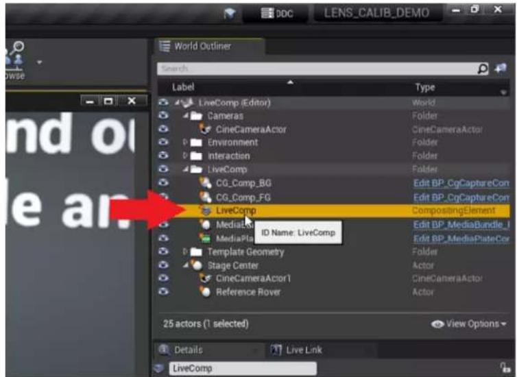
- In the World Outliner panel, select the LiveComp element to view the results.
After configuring the media source, you're ready to import calibration data. For details, see Importing calibration data into Unreal Engine on page 29.
FAQs
How many base stations can I use?
You can use up to four base stations in a single VIVE Mars CamTrack setup with an area of up to 10 m x 10 m (32 ft 10 in x 32 ft 10 in).
You'll need to set up at least two base stations for minimum tracking coverage.
Can I use an odd number of base stations?
Yes. Each base station works independently of each other, and there is no pairing requirement among them.
Because at least two base stations are required for minimum tracking coverage and you can use a maximum of four base stations, the only possible setup with an odd number of base stations would have a total of three base stations.
Cleaning the base stations
Always keep the base stations and their power adapters dry and away from liquids to avoid shock hazard.
To clean the base stations:
- Unplug and unmount the base stations.
- Use a lightly moistened non-abrasive cloth to clean the base stations. Do not use cleaning chemicals.
- While cleaning the base stations, do not scratch the front panel nor disassemble any of its parts.
Can I use more than one VIVE Tracker (3.0)?
You can use up to three VIVE Tracker (3.0) units in a VIVE Mars CamTrack setup.
You'll need at least two VIVE Tracker (3.0) units for a basic VIVE Mars CamTrack setup—one for your camera, and one for the calibration board.
Why does VIVE Tracker (3.0) automatically turn off?
If VIVE Tracker (3.0) turns off by itself, it's most likely because the battery is drained.
Normally, VIVE Tracker (3.0) turns off after going idle or after pairing times out. However, when connected to Mars, VIVE Tracker (3.0) will never go idle or time out.
How do I verify that VIVE Tracker (3.0) is detected?
You can check the Mars dashboard to see if VIVE Tracker (3.0) is detected by Mars.
When VIVE Tracker (3.0) is detected, the VIVE Tracker (3.0) icon will flash blue. When the icon turns solid blue, VIVE Tracker (3.0) is detected and actively tracking.
What does the status light on VIVE Tracker (3.0) mean?
The status light on the tracker turns white or orange according to the following behaviors:
- White: VIVE Tracker (3.0) is working normally and fully charged.
- Orange: VIVE Tracker (3.0) is working normally and charging.
Why doesn't the VIVE Tracker (3.0) status icon on the Mars dashboard turn blue?
If the status icon doesn't turn blue, check that the Mars firmware is up to date.
Troubleshooting VIVE Tracker (3.0)
If VIVE Tracker (3.0) cannot be detected by Mars, try the following:
■ Make sure that VIVE Tracker (3.0) is in the field of view of at least one base station.
■ Turn VIVE Tracker (3.0) off and on again to reactivate tracking.
- Restart Mars.
Why can't I see the incoming video feed in the Camera Calibration Tool?
46 FAQs
Depending on how your video capture device is configured, the Camera Calibration Tool might not display the incoming video feed.
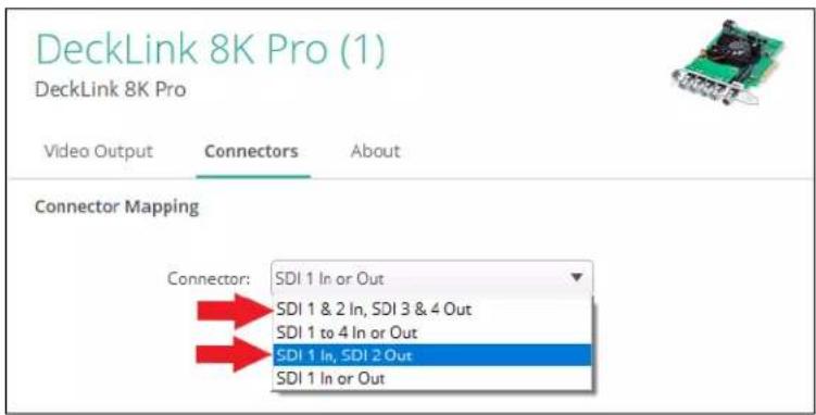
If the Camera Calibration Tool doesn't display the incoming video feed after you select a video source, try reconfiguring your video capture device. For example, if you're using a Blackmagic DeckLink 8K Pro, you can resolve this issue by configuring the connector mapping as follows:
- In the Blackmagic Desktop Video Utility, select your device, and then click the settings icon
- Click the Connectors tab.
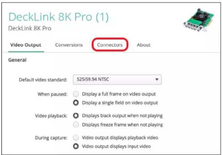
- Under Connector Mapping, select one of the following for Connector:
■ SDI 1 & 2 In, SDI 3 & 4 Out
■ SDI 1 In, SDI 2 Out
Trademarks and copyrights
©2022 HTC Corporation. All Rights Reserved.
VIVE, the VIVE logo, HTC, the HTC logo, and all other HTC product and service names are trademarks and/or registered trademarks of HTC Corporation and its affiliates in the U.S. and other countries.
Steam, the Steam logo and SteamVR are trademarks and/or registered trademarks of Valve Corporation in the U.S. and/or other countries.
All other trademarks and service marks mentioned herein, including company names, product names, service names and logos, are the property of their respective owners and their use herein does not indicate an affiliation with, association with, or endorsement of or by HTC Corporation. Not all marks listed necessarily appear in this User Guide.
Screen images contained herein are simulated. HTC shall not be liable for technical or editorial errors or omissions contained herein, nor for incidental or consequential damages resulting from furnishing this material. The information is provided “as is” without warranty of any kind and is subject to change without notice. HTC also reserves the right to revise the content of this document at any time without prior notice.
No part of this document may be reproduced or transmitted in any form or by any means, electronic or mechanical, including photocopying, recording or storing in a retrieval system, or translated into any language in any form without prior written permission from HTC.
- Hardware
- System setup
- Camera calibration
- Real-time compositing in Unreal Engine
- FAQs
- About this guide
- Introduction
- About VIVE Mars CamTrack
- What's inside the box?
- No. Item Quantity
- SteamVR Base Station 2.0
- VIVE Tracker (3.0)
- Rover
- Mars
- Mars dashboard
- Icon Device status
- Calibration kit
- Setting up VIVE Mars CamTrack
- Example virtual production studio setup
- Connecting Mars to your PC
- Mounting VIVE Tracker (3.0) to Rover
- Connecting Rover to Mars
- Setting up the base stations
- Tips for setting up the base stations
- Adding Mars as an endpoint in Unreal Engine
- Enabling FreeD on Mars and adding Mars to Aximmetry
- Manually updating the Mars firmware
- Setting up the calibration board
- Collecting calibration data using the Camera Calibration Tool
- Importing calibration data into Unreal Engine
- In the World Outliner panel, select your CineCameraActor.
- Go to the Details panel and select LiveLinkComponent Controller. Select Live Link Camera Controller as the Camera Role and then select your Lens File.
- Creating a project with a virtual production template
- Connecting to Mars using the Live Link plug-in
- Setting up the virtual camera using the Live Link Controller
- For Subject Representation, select Rover 1.
- Configuring the media source using Composure
- In the World Outliner panel, select MediaBundle-01.
- In the Details panel, double-click the icon under Media Bundle to open the configuration panel.
- How many base stations can I use?
- Can I use an odd number of base stations?
- Cleaning the base stations
- Can I use more than one VIVE Tracker (3.0)?
- Why does VIVE Tracker (3.0) automatically turn off?
- How do I verify that VIVE Tracker (3.0) is detected?
- What does the status light on VIVE Tracker (3.0) mean?
- Why doesn't the VIVE Tracker (3.0) status icon on the Mars dashboard turn blue?
- Troubleshooting VIVE Tracker (3.0)
- Why can't I see the incoming video feed in the Camera Calibration Tool?
- Trademarks and copyrights
Brand : HTC
Model : Vive Mars CamTrack
Category : Virtual reality headset