
EXI 02 LAN - Network Card/Adapter KATHREIN - Free user manual and instructions
Find the device manual for free EXI 02 LAN KATHREIN in PDF.


| Product Type | Network Adapter / LAN Card |
| Brand | Kathrein |
| Model | EXI 02 LAN |
| Interface | PCI Express |
| Data Rate | 10/100/1000 Mbps (Gigabit Ethernet) |
| Connector | RJ45 |
| Dimensions (approx.) | 120 x 65 x 20 mm |
| Weight (approx.) | 50 g |
| Power Consumption | 2.5 W (from PCIe slot) |
| Operating Temperature | 0°C to 40°C |
| Storage Temperature | -20°C to 70°C |
| Supported Standards | IEEE 802.3, IEEE 802.3u, IEEE 802.3ab |
| LED Indicators | Link/Activity (green) |
| Driver Support | Windows, Linux, macOS |
| Maintenance | Keep contacts clean; avoid dust; use compressed air if needed |
| Safety | Install in anti-static environment; power off before installation |
| Spare Parts & Repairability | No user-serviceable parts; replace unit if faulty |
| General Information | Designed for desktop PCs; plug and play |
Frequently Asked Questions - EXI 02 LAN KATHREIN
User questions about EXI 02 LAN KATHREIN
0 question about this device. Answer the ones you know or ask your own.
Ask a new question about this device
Download the instructions for your Network Card/Adapter in PDF format for free! Find your manual EXI 02 LAN - KATHREIN and take your electronic device back in hand. On this page are published all the documents necessary for the use of your device. EXI 02 LAN by KATHREIN.
USER MANUAL EXI 02 LAN KATHREIN
Kathrein Ethernet over Coax System "K-LAN 2.4"
About these instructions
This document is part of the product.
▶ Do not install and use the device until you have read and understood this document.
▶ Always perform the actions described in this document in the sequence listed.
▶ Keep this document for reference throughout the life of the device. Pass this document on to any subsequent owners and users.
The current version of this document can be found at www.kathrein-ds.com.

You can download an English version of this user manual from our homepage www.kathrein-ds.com.
Features
■ G.hn modem for the Kathrein Ethernet over Coax System "K-LAN 2.4"
■ Using the existing coax terrestrial distribution system to create a home network. No need to lay network cables
■ Improved data throughput of up to 2 Gbit/s
■ 16 modems can be connected concurrently within the network
■ Integral high selectivity diplexer to prevent interference between DVB-T and SAT signals
■ Integral switch for connection of 2 network devices
■ Coax range up to 700 m
■ Supports both IPv6 and IPv4
■ Not compatible with series EXI 01 modems
Scope of supply
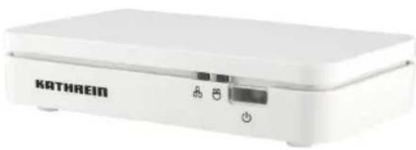
EXI 02 LAN
■ Efficient plug-in power supply unit
■ CAT 6 network cables
■ Operating instructions
Accessories
EXI 258 high-pass filter for suppression within the G.hn operating range. The high-pass filter is screwed into the input for the terrestrial distribution system. By this means
for instance the following multi-switches and splitters can be isolated from G.hn, and the emissions by a terrestrial antenna can be prevented (see "System examples" on page 4).
natural_image
White KATHREIN device with control buttons and indicator lights (no readable text or symbols beyond branding)
Intended use
The EXI 02 LAN modem is designed exclusively for use with the Kathrein Ethernet over Coax System "K-LAN 2.4".
Any other use, or failure to comply with these instructions and the documentation and instructions supplied with the devices will result in voiding of the warranty cover.
Installation and safety instructions

▶ Failure to comply with these instructions will result in voiding of the warranty cover.
The equipment may be installed and operated only in dry indoor areas. Use the drilling template (see "Dimensions and drilling template for wall mounting" on page 5) for wall mounting.
▶ Make sure that the ventilation slots on the device are not covered in any way.
▶ Connection plugs for coaxial cables: 75 Ohm HF plugs (series F)
▶ If the port is not used for connection of a TV set or a similar device, an EMK 03 terminating resistor must be screwed into the port.
Connections and LEDs

① Ethernet LED
② G.hn link LED
③ Power LED

① Pairing button
② Power socket
③ Network port 1
④ Network port 2
⑤ Reset button
⑥ TV port
⑦ Antenna outlet
Interpretation of the LED statuses
Power LED (network security)
Continuous orange

Operation, also "insecure mode" and readiness for "pairing" with other modems for "secure mode"
Flashing orange/green

Pairing procedure with other modems for "secure mode"
Continuous green Operation and "secure mode" with other modems in the same network
Off No operating voltage present
G.hn link LED (coax connection of the modem)
Flashing green Effective data rate is > 300 Mbps
Flashing orange Effective data rate is ≤ 300 Mbps
Flashing red

Effective data rate is ≤ 100 Mbps
Continuous red/green/orange
Effective data rate is the same as for the flashing LED, but no data traffic over the coax connection
Off

No link available over the coax. Either the attenuation or distance is too great or the modem is solitary in its logical network
Ethernet LED
Continuous red Ethernet port 1 connected
Continuous green Ethernet port 2 connected
Flashing red/green Data traffic over the respective port
Commissioning
- Plug the power supply unit supplied into the power socket and into the mains socket (the power LED will light up orange).
- Connect the modem to the antenna socket using a coaxial cable (with F plugs).
- Using the Ethernet cable supplied, connect the network device such as a router, TV, PC etc.
- Further modems can be connected as described in steps 1 to 3.
Pairing
A secure G.hn network connection can be created by pressing the pairing button on the modem and proceeding as follows:
- Check that power LEDs of the modems are lit up continuously orange (ex factory status or after a reset: "insecure mode").
- Depress the pairing button on the first modem for about 3 seconds. The power LED will start to flash orange/green.
- Depress the pairing button on the next modem for about 3 seconds. The power LED will start to flash orange/green.
- On completion of the procedure, the power LED of the second modem will light up continuously green. The power LED of the first modem will continue to flash orange/green for about 2 minutes, to allow you to add further modems to the network.
- To add further modems to the network, repeat step 3.
- Once all modems are attached to the network, all the power LEDs will light up continuously green. The network connection is now in "secure mode".
Removing a modem
To remove a modem from the secure network, or to perform a reset, proceed as follows:
- Using a pointed object, depress the reset button for about 15 seconds. All the LEDs will go dark briefly.
- After a short time the power LED will light up continuously orange. The modem is now once again in "insecure mode" and by pressing the pairing button can be attached to a secure network.
Installation example

flowchart
graph TD
    A["PC/Laptop"] --> B["EXI 02 LAN"]
    B --> C["Sat"]
    B --> D["TV Radio"]
    B --> E["Sat Radio"]
    B --> F["Coaxial cable DVB-T2"]
    B --> G["Coaxial cable DVB-S2"]
    B --> H["Ethernet cable"]
System examples

flowchart
graph TD
    A["UAS 584 (585)"] --> B["KAZ 11/12"]
    B --> C["EXI 258 | EXR 2508"]
    C --> D["PC/Laptop"]
    C --> E["EXI 02 LAN"]
    C --> F["EXI 02 LAN"]
    C --> G["EXI 02 LAN"]
    D --> H["ESD 30"]
    E --> I["ESD 30"]
    F --> J["ESD 30"]
    G --> K["TV-Gerit SAT"]
    G --> L["VDSL"]
    G --> M["Router"]
    G --> N["NAS-System"]
    C --> O["Sat-ReCoVer"]
    C --> P["TV-Gerat SAT / DV8-T2"]
    C --> Q["DAB+ 100 highline"]
    style A fill:#f9f,stroke:#333
    style B fill:#ccf,stroke:#333
    style C fill:#cfc,stroke:#333
    style D fill:#fcc,stroke:#333
    style E fill:#cff,stroke:#333
    style F fill:#ffc,stroke:#333
    style G fill:#cfc,stroke:#333
    style H fill:#fcc,stroke:#333
    style I fill:#fcc,stroke:#333
    style J fill:#fcc,stroke:#333
    style K fill:#fcc,stroke:#333
    style L fill:#fcc,stroke:#333
    style M fill:#fcc,stroke:#333
    style N fill:#fcc,stroke:#333
    style O fill:#fcc,stroke:#333
    style P fill:#fcc,stroke:#333
    style Q fill:#fcc,stroke:#333

flowchart
graph TD
    A["UAS 584"] -->|KAZ 11/12| B["Exi 258 | EXR 2558"]
    B -->|ESD../ESC../EXI..| C["EXI 258 | EXR 2508"]
    C -->|ESD../ESC../EXI..| D["EXI 02 LAN"]
    D -->|EXI 02 LAN| E["EXI 02 LAN"]
    E -->|EXI 02 LAN| F["EXI 02 LAN"]
    F -->|EXI 02 LAN| G["EXI 02 LAN"]
    G -->|EXI 02 LAN| H["EXI 02 LAN"]
    H -->|EXI 02 LAN| I["EXI 02 LAN"]
    I -->|EXI 02 LAN| J["EXI 02 LAN"]
    J -->|EXI 02 LAN| K["EXI 02 LAN"]
    K -->|EXI 02 LAN| L["EXI 02 LAN"]
    L -->|EXI 02 LAN| M["EXI 02 LAN"]
    M -->|EXI 02 LAN| N["EXI 02 LAN"]
    N -->|EXI 02 LAN| O["EXI 02 LAN"]
    O -->|EXI 02 LAN| P["EXI 02 LAN"]
    P -->|EXI 02 LAN| Q["EXI 02 LAN"]
    Q -->|EXI 02 LAN| R["EXI 02 LAN"]
    R -->|EXI 02 LAN| S["EXI 02 LAN"]
    S -->|EXI 02 LAN| T["EXI 02 LAN"]
    T -->|EXI 02 LAN| U["EXI 02 LAN"]
    U -->|EXI 02 LAN| V["EXI 02 LAN"]
    V -->|EXI 02 LAN| W["EXI 02 LAN"]
    W -->|EXI 02 LAN| X["EXI 02 LAN"]
    X -->|EXI 02 LAN| Y["EXI 02 LAN"]
    Y -->|EXI 02 LAN| Z["EXI 02 LAN"]
    Z -->|EXI 02 LAN| AA["EXI 02 LAN"]
    AA -->|EXI 02 LAN| AB["EXI 02 LAN"]
    AB -->|EXI 02 LAN| AC["EXI 02 LAN"]
    AC -->|EXI 02 LAN| AD["EXI 02 LAN"]
    AD -->|EXI 02 LAN| AE["EXI 02 LAN"]
    AE -->|EXI 02 LAN| AF["EXI 02 LAN"]
    AF -->|EXI 02 LAN| AG["EXI 02 LAN"]
    AG -->|EXI 02 LAN| AH["EXI 02 LAN"]
    AH -->|EXI 02 LAN| AI["EXI 02 LAN"]
    AI -->|EXI 02 LAN| AJ["EXI 02 LAN"]
    AJ -->|EXI 02 LAN| AK["EXI 02 LAN"]
    AK -->|EXI 02 LAN| AL["EXI 02 LAN"]
    AL -->|EXI 02 LAN| AM["EXI 02 LAN"]
    AM -->|EXI 02 LAN| AN["EXI 02 LAN"]
    AN -->|EXI 02 LAN| AO["EXI 02 LAN"]
    AO -->|EXI 02 LAN| AP["EXI 02 LAN"]
    AP -->|EXI 02 LAN| AQ["EXI 02 LAN"]
    AQ -->|EXI 02 LAN| AR["EXI 02 LAN"]
    AR -->|EXI 02 LAN| AS["EXI 02 LAN"]
Dimensions and drilling template for wall mounting
Diagram showing the rear of the EXI 02 LAN. Here you will find the adhesive label with the identifications.

Installation instructions
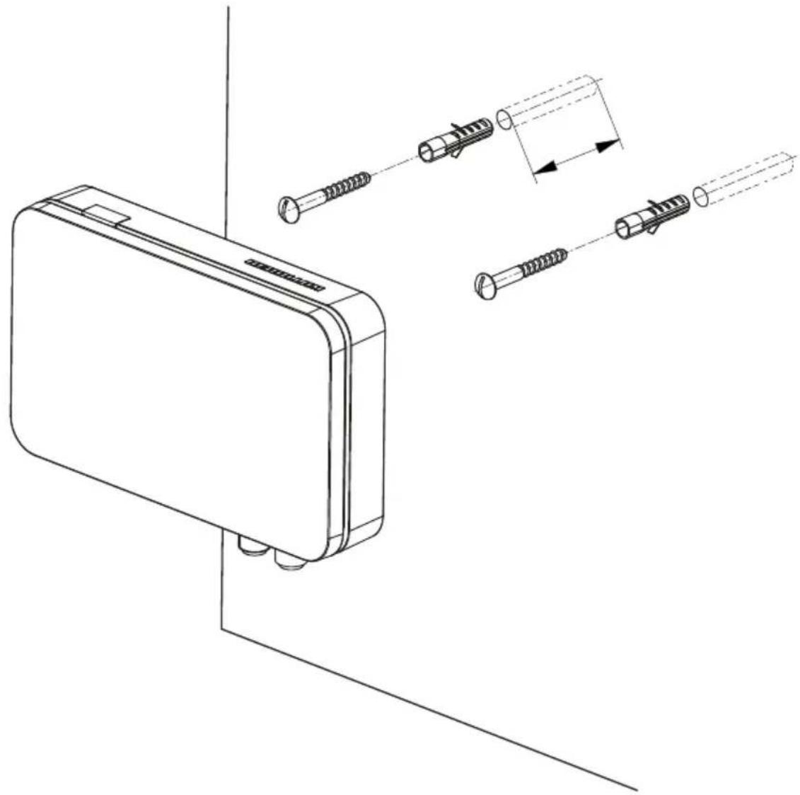
To mount the EXI 02 LAN on the wall you will need fastenings such as 2 round head wood screws (size
4 x 16 mm) and suitable wall plugs. Make sure that the diameter of the screw heads does not exceed 9 mm (see
"Dimensions and drilling template for wall mounting" on page 5).
The fastening materials are not included in the scope of supply.
Select screws and wall plugs suitable for the wall to which the modem is to be fastened, so as to achieve optimum security of attachment.
To attach the modem, proceed as follows:
- Drill holes to suit the sizes of the wall plugs
- Insert the wall plugs flush into the drilled holes
- Screw the screws into the wall plugs until their heads are projecting approx. 3 mm, so that the modem can be located over them
- Place the modem on the screws and push it downwards so that it is located in position
natural_image
Technical line drawing of a mechanical device with multiple inserted screws and a cylindrical component, shown without any text or symbols.Information about the coaxial distribution system
In principle, any coaxial distribution system in the house can be used. The requirement is that a frequency range of 200 MHz is available and is not being used for other purposes, because otherwise interference can occur. G.hn is robust can be expected to achieve a connection even under very adverse conditions. Do not use the modems in cable network environments in which the same frequency range is used. Only appropriately trained personnel may undertake a secure installation.
Technical data
| Type | Order no. EXI 02 LAN | 205500006 | ||
| Frequency range IP + TV MHz 2 – 1218 | ||
| Frequency range IP MHz 2 – 200 | ||
| Frequency range TV MHz 258 – 1218 | ||
| Through loss, TV dB 2 | ||
| Modem current consumption mA 250 | ||
| Phy rate Gbit/s 2 | ||
| Data rate TCP (gross) max. Mbit/s | 900 | |
| Ports | F connectors, RJ45, DC socket 5.5 x 2.5 mm | |
| Standards supported | G.hn G.9960 1-4 | |
| Permissible ambient temperature | °C | 0 to +40 |
| Dimensions (W x L x H) | mm | 92 x 130 x 29 |
| Weight | kg | 0.125 |
| Power supply unit | ||
| Nominal input voltage | V | 230 |
| Voltage secondary | V | 12 |
| Output current max. | A | 1 |
| Nominal input power (250 mA load) | W | 3 |
Disposal
Electronic equipment
Electronic equipment must not be disposed of in domestic waste. According to directive 2012/19/EU OF THE EUROPEAN PARLIAMENT AND COUNCIL of 4 July 2012 on waste electrical and electronic equipment, it must be disposed of professionally. At the end of its service life, take this unit to a designated public collection point for disposal.
For your notes
- Kathrein Ethernet over Coax System "K-LAN 2.4"
- About these instructions
- Features
- Scope of supply
- Accessories
- Intended use
- Installation and safety instructions
- Connections and LEDs
- Interpretation of the LED statuses
- Power LED (network security)
- G.hn link LED (coax connection of the modem)
- Ethernet LED
- Commissioning
- Pairing
- Removing a modem
- Installation example
- Dimensions and drilling template for wall mounting
- Installation instructions
- Information about the coaxial distribution system
- Disposal
- Electronic equipment
- For your notes
Brand : KATHREIN
Model : EXI 02 LAN
Category : Network Card/Adapter