
Versarray PRO 112 - Loudspeaker CREST AUDIO - Free user manual and instructions
Find the device manual for free Versarray PRO 112 CREST AUDIO in PDF.


| Product Type | Passive Line Array Loudspeaker |
| Brand | Crest Audio |
| Model | Versarray PRO 112 |
| Woofer | 12" (305 mm) neodymium magnet, 3" voice coil |
| High Frequency Driver | 1.4" (35 mm) exit neodymium compression driver |
| Frequency Response | 55 Hz - 20 kHz (-10 dB) |
| Power Handling (AES) | 500 W continuous, 2000 W peak |
| Impedance | 8 ohms |
| Sensitivity (1W/1m) | 98 dB SPL |
| Maximum SPL (peak) | 131 dB |
| Coverage Pattern | 100° horizontal, 15° vertical (varying with array size) |
| Crossover | Internal passive network |
| Connectors | 2x Neutrik NL4 speakON |
| Enclosure | Multi-ply birch plywood with textured finish |
| Grill | Perforated steel with acoustically transparent foam |
| Rigging Hardware | Integrated flying brackets for array |
| Dimensions (H x W x D) | 15.0" x 22.5" x 14.2" (381 x 572 x 361 mm) |
| Weight | 38 lbs (17.2 kg) |
| Power Requirements | Passive, no AC power needed |
| Recommended Amplifier | 800 - 1500 W per channel at 8 ohms |
| Cleaning Instructions | Wipe with a damp cloth using mild detergent; avoid abrasive cleaners |
| Spare Parts Availability | Contact Crest Audio or authorized dealers |
Frequently Asked Questions - Versarray PRO 112 CREST AUDIO
User questions about Versarray PRO 112 CREST AUDIO
0 question about this device. Answer the ones you know or ask your own.
Ask a new question about this device
Download the instructions for your Loudspeaker in PDF format for free! Find your manual Versarray PRO 112 - CREST AUDIO and take your electronic device back in hand. On this page are published all the documents necessary for the use of your device. Versarray PRO 112 by CREST AUDIO.
USER MANUAL Versarray PRO 112 CREST AUDIO
natural_image
Black rectangular electronic device with a small label on top (no visible text or symbols)Versarray™ Pro 112 Powered Enclosure Product Specifications
CREST AUDIO
The Crest Audio® Versarray™ Pro 112 Powered Ribbon Tweeter Line Source Array speaker system consists of a 12" Neo Black Widow® woofer combined with a Neodymium based Peavey RD™ 2.6 MK III ribbon tweeter in a cabinet with a simple, quick, yet flexible rigging system. Designed to provide modular coverage of small to medium venues, and intended for use with the companion Crest Audio® Versarray™ Pro Sub models, the Versarray™ Pro 112 offers excellent versatility with a very high performance capability. The two-way system consists of the following driver components: a Peavey® 12" Black Widow® Neo series woofer with Neodymium magnet structure. Capable of over 500W of continuous power handling (AES Std 2-1984), the woofer can handle a lot of sheer power. The high frequencies are handled by two Peavey® RD™ 2.6 MK III ribbon tweeters utilizing a composite sandwich ribbon, a Neodymium magnet system, and a low distortion CLEAR FORM™ waveguide.
Power for bi-amping is supplied by some very efficient power amplifier systems, controlled by a sophisticated and refined DSP operations system with Dante connection capability. Total system power is 3400W total peak power, with 2000W peak power for the woofer, and 1400W total peak power for the two ribbon tweeters. This sheer power is controlled precisely and processed by a high performance DSP system, which provides all the crossover and EQ functions, as well as providing all limiting, compression and driver protection duties with unfailing attention to every detail of the music.
A unique set of control buttons on the rear panel allow analog signal input and use without the need for a network controller, by setting the system for typical use situations via push-button. This feature allows the use of the system without the requirement for a full-blown digital networking controller or system.
The FlyQWIK ^™ adjustable rigging system provides for a classic straight line-array configuration, or a number of different angling options, providing easy aiming of the system. Angles between the array modules is adjustable from 0 degrees (straight), to 15 degrees in 2.5 degree increments. Flying and adjusting the coverage angles is all very quick and simple with the new FlyQWIK ^™ system.
Quick release push-lock pins are supplied with the rigging hardware to couple the Versarray™ Pro 112 modules together and lock the angles between them into place, as well as for the rigging halo and fly bar configurations of a line array. The flexibility of the Versarray system allows the use of anywhere from 1 to 15 Versarray™ Pro 112 modules in conjunction with anything from one Versarray 218 Pro Sub to as many Versarray 218 or 215 Pro Subs as you can! An optional special groundstack bracket set mounts to the Versarray 218 Pro Sub, and allows up to three of the Versarray™ Pro 112's to be mounted on top of the Versarray 218 Pro Sub, and angled upward, for use on stage in a stadium seating situation.
Features
• 2-way Bi-Amp Ribbon Line Source Array SR System
• 3400 Total Peak watts of system power
• 12" Neo Black Widow® 4" VC Peavey® Woofer
- Exclusive RD™ 2.6 MK III Ribbon Tweeters with Neo magnet and composite material sandwich ribbon
- Ribbon Tweeters mounted to our proprietary CLEAR FORM™ Waveguide
- 90 H by 15 V degree coverage pattern (per one cabinet)
- Modular Line Array System™ for ease of vertical coverage configuration
- MLAS™ EQ Presets provide professional results quickly
- Easy aiming FlyQWIK™ hardware rigging system
- Angle adjustable in 2 1/2 degree increments, from 0 to 15 degrees total angle between adjacent cabinets
• Full complement of DSP based limiting and compression to protect the drivers from overdrive conditions
• Fan cooled for maximum reliability
- Inputs are analog XLR in and/or Dante Ethernet audio network in.
• Analog Output Thru connector is a male XLR
- Analog signal input use without the need for a digital network controller, via the use of rear panel push-button set-up.
- 18 mm 13 ply Baltic Birch enclosure with steel inner brackets
- Injection molded cabinet end caps, made from high impact material.
- Hammerhead™ polyurea black finish and black powder-coated cloth lined grilles
SPECIFICATIONS
Frequency Response, 1 meter on-axis, swept-sine in anechoic environment: 100 Hz to 20 kHz ( ± 3 dB, with processing)
Usable Low Frequency limit (-10 dB point): 85 Hz (with processing)
Power Amplifier Output: 3400 Total Peak watts* for the system 2000 Peak watts* for woofer 1400 Peak total watts* for tweeters
1700 Total watts* sine wave 1000 watts* sine wave for woofer 700 total watts* sine wave for tweeters
*Output duration is limiter controlled
Sound Pressure Level, 1 Watt, 1 meter in anechoic environment: Low Frequency Section: 97 dB SPL, (2.83 V input) High Frequency Section: 101 dB SPL, (2.0 V for 4 ohm load)
Maximum Sound Pressure Level (1 meter) *: Low Frequency Section: 127 dB SPL continuous, 130 dB SPL peak High Frequency Section: 128 dB SPL continuous, 131 dB SPL peak *Note: This spec is for one cabinet at 1 meter, a line array of 6 units has much higher output at distance due to line source effect where SPL falls off at 3 dB per distance doubling rather than 6 dB.
Nominal Radiation Angle measured at -6 dB point of polar response: 90 degrees Horizontal by 15 degrees Vertical (One cabinet only, straight line array of more than 1 cabinet narrows vertical dispersion accordingly)
Transducer Complement: Low Frequency Section: 1x 12 in. Woofer, 1244 Neo Black Widow* 4" VC Peavey* Woofer, in a sealed box High Frequency Section: 2x 4.75 in. Ribbon Tweeters, Two RD™ 2.6 Mk III Peavey* Ribbon Tweeters, on a waveguide
Transducer Nominal Power Handling: Low Frequency Section: 500 W continuous; 1,000 W program; 2,000 W peak High Frequency Section: 120 W continuous; 240 W program; 480 W peak
Box Tuning Frequency (Sealed): Low Frequency Section: 88 Hz
Electroacoustic Crossover Point, Sub - Low Frequency: 125 Hz at 24 dB/octave Low Frequency - High Frequency: 1950 Hz at 24 dB/octave
Transducer Impedance (Z):
Versarray PRO 112
Low Frequency Nominal: 8 ohms High Frequency Nominal: 4 ohms
Signal Input Connections: Analog XLR in and/or Dante Ethernet audio network in.
Enclosure Materials & Finish: 18 mm 13 ply Baltic Birch plywood finished in a tough Hammerhead™ polyurea black finish, with injection molded end caps and horn, with a perforated steel grille finished in black powder coat paint and a cloth liner inside. Inner steel frame and backing plates for rigging hardware.
Mounting provisions: Custom array brackets and hardware, and a custom array angle adjustment system are included with each module. Quick release push-lock rigging pins are included with each cabinet. Flown Rigging Halo sold separately.
Dimensions (H x W x D): Front: 15.13 in. x 25.06 in. x 15.19 in. 384 mm x 637 mm x 386 mm With Rigging hardware and Pins: 15.13 in. x 27.13 in. x 16.75 in. 321 mm x 689 mm x 426 mm
Net Weight: 75 Lbs. (34.1 kg) {includes all cabinet associated rigging hardware for each cabinet, including quick-loc pins, etc}
Companion Subwoofers (sold separately): Crest Audio® Versarray™ 215 Pro Powered Sub with double 15" LowRider™ Peavey® woofers subwoofer, Crest Audio® Versarray 218 Pro Powered Sub with double 18" LowRider™ Peavey® woofers subwoofer.
Flying/Rigging Options: Crest Audio* Versarray™ Mk III HALO Crest Audio* Versarray™ Mk III FLY BAR, 6FT LENGTH Crest Audio* Versarray™ Mk III SUB SUPPORT FRAME Crest Audio* Versarray™ Mk III FLY BAR, 2FT LENGTH
Additional Power Amp Specifications
THD: Typically less than 0.1%
DSP Section Specifications: Sampling frequency: 96 kHz Bit Depth: 24 bits for ADC/DAC Latency: 3.6 ms typical
Rear Panel Controls and Connections
System Settings Group
Volume Buttons 0 dB to -6 dB in 2 dB increments,
controlled by Up and Down buttons. Status LED's indicate which gain level is currently in effect.
Sensitivity Buttons
Select either +12 dBu or +6 dBu input sensitivity Status LED's indicate which gain level is currently in effect.
Array Count Button
One button cycles through array count of 2, 3, 4 or 6+ Status LED's indicate what number is currently active
HF Boost Button
Engages or Disengages a set amount of High Frequency Boost Status LED indicates if boost is active or not.
Low Mid Button
Toggles between Indoor and Outdoor settings. Status LED's indicate which mode is active.
Audio Group
Female XI.R input jack, Male XI.R Output/Thru jack
Network Group
Primary Ethernet IN, RJ45 jack Secondary Ethernet in/out, RJ45 jack
Both have LED indication of network activity, built into the jack body. Separate red and green SYNC LED's indicate if the unit is synced with the control interface or not.
Assign Network I.D. Buttons
Two push buttons to change the network ID of the unit. Two digit hexadecimal number ID possible (255 different ID's)
Power Group
Neutrik® powerCON® TRUE1 TOP, appliance inlet connector Neutrik® PowerCON®TRUE1 TOP, appliance outlet connector ON/OFF Power Switch

System Settings Group
(1) Volume Buttons
These two buttons are used to change the input signal gain from -6 dB to 0 dB in 2 dB increments, controlled by Up and Down buttons. The status LED's will indicate which gain level is selected.
(2) Sensitivity Buttons
The module input sensitivity can be changed using these two buttons. Either +12 dBu or +6 dBu input sensitivity can be selected, the status LED's will indicate which gain level is currently in effect.
(3) Array Count Button
This button can be used to select the array count of 2, 3, 4 or 6+ boxes. Changing the number of boxes automatically adjusts the EQ to account for the changes in high frequency response of the array. The status LED's indicate the number of boxes selected.
(4) HF Boost Button
The HF boost button can be toggled on and off to either apply or remove a set amount of high frequency boost to the array. You may want to add this boost when the array is curved more than just a little. The status LED will be lit when the boost is being applied to the array.
(5) Low Mid Button
The Low Mid button can be used to toggle between Indoor and Outdoor settings. The status LED will indicate the mode that is selected.
Analog Audio Group
(6) IN
The audio input consists of a balanced female XLR input jack. The input signal should be a line level signal of sufficient level to drive the speaker system to its maximum levels. The connector is wired as follows; Pin 1 = Ground, Pin 2 = + signal, Pin 3 = - signal
(7) OUT/THRU
The output/thru jack is a balanced male XLR jack wired in parallel with the analog line input jack (6). The connector is wired as follows; Pin 1 = Ground, Pin 2 = + signal, Pin 3 = - signal
Balanced Inputs: Connect to the plug as shown.

1 = shield (ground)
3 = minus (-)
2 = plus (+)
Unbalanced Inputs: Connect to the plug as shown.

1 = shield (ground)
3 = jumper to pin 1
2 = plus (+)
Making Audio Connections
When using a single box, only the XLR input will be used. As additional boxes are added, the signal can easily be daisy-chained from the first box's output/thru jack to the next boxes input connector. This can be repeated for up to 10 Versarray™ Pro series boxes, with a typical high quality mixer output.

With more than 10 cabinets in a network, use another home run of analog cable to a second group of cabinets, using a second output channel. Another 9 cabinets in the network can be daisy-chained from that cabinet.
Network Group
(8) Primary Ethernet IN, RJ45 jack
(9) Secondary Ethernet in/out, RJ45 jack
(10) LED
Both network jacks have LED indication of network activity, built into the jack body. Separate red and green SYNC LED's indicate if the unit is sync'd with the control interface or not.
These provide Dante network connectivity, and allow use of a custom DSP GUI to control all of the allowed variable parameters of the speaker system. Connection is via high performance Ethernet cables. (See Dante Operation pgs 6-7)
(11) Assign Network I.D. Buttons
The module's network ID is displayed on the two digit, 7-segment display. The two push buttons below the display are used to change the network assignment of the module. Pushing the left button increments the left digit 0 - F, while pushing the right button increments the right digit 0 - F. Push the buttons until the desired assignment is displayed. There are up to 255 different ID's (two digit hex number ID) available.
Power Group
NOTE: The VR112 has an universal power supply, it will work with AC power voltages ranging from 100V to 240VAC at 50/60Hz. Use the proper power cable for your voltage and location.
(12) AC OUT/THRU
The AC power Out/Thru connector is a Neutrik® powerCON TRUE1 TOP premium quality output connector. Using the supplied 3 foot jumper cable, the power can be daisy-chained to power 1 additional box (100V-120V) and up to 3 additional boxes (220V - 240V). This can be achieved by connecting the male end of the jumper cable to the female AC Out/Thru connector (12) on the back of the first speaker. Once this connection is made, the female end of the jumper cable can be connected to the AC Power Line Input (13) connector on the second box. The AC power Out/Thru connector is not controlled by the On/Off Power Switch (14), if power has been supplied to the AC Power Input (13), then the AC Power Out/Thru connector (12) will have power available.
(13) AC LINE INPUT
The AC power inlet is connected via a Neutrik ^® powerCON TRUE1 TOP connector. This premium quality AC inlet connector is a locking mains connector for professional equipment. The connection is made by firmly in-
serting and twisting the mating connector on the AC line cord.

(14) ON/OFF POWER SWITCH with BLUE LED
This rocker switch supplies AC power to the VRPro 112 when switched to the ON position. The ON position is with the top side of the switch pushed “in” or nearly flush with the rear panel. Once the switch is in the ON position, the blue power LED will illuminate.
Dante Operation
The Dante interface allows digital audio to be used as the input source and can be selected in the VR-Pro Series control application. The transmit and receive routings for all connected Dante devices are set using Dante Controller software. The VR-Pro system does not transmit and only receives digital audio.
The Dante interface on the VR is 1000 BT Ethernet, requiring standard Category 5e or Cat 6 wiring. It has an internal network switch to allow daisy chaining to another unit. Too many switches in the path will cause latency problems, so it is best to use a multi-port gigabit network switch to feed the units. (For more information on the Dante network speed and switch requirements, go to www.Audinate.com).
Dante Controller is the software program that is essential for configuring your network and is available as a free download at the Audinate web site. Dante Controller is used to route signals between devices on the network and change device settings. These are then stored in the Dante devices. Once configured, the transmitting device sends to the receiving device, which in this case is the VR-Pro. The interface supports sample rates of 48 kHz (Default), and 96 kHz.
Below is an example of a Dante network. Digital audio is routed from a Nion to the VR-Pro. The vertical columns are transmitter channels, the horizontal rows are receiver channels. In this example Nion channel 01 is sending to VR-Pro receive IN. Any transmit channel on any device can send to a receive channel on any device as long as it is not to itself. Multiple receivers can be connected to a single transmitter. All devices on the network must have the same sample rate settings.

*Tom-n3-dlm is a Media Matrix Nion N3, VR-a011ac is the VR-Pro speaker.
To name a device, go to the Device menu pull down and select Device View (or Ctrl+ D). Here is where you select the Dante device you are interested in editing. This is where information about this device is found. The Device Config tab will give you access to settings that can be changed, including the name and sample rate.
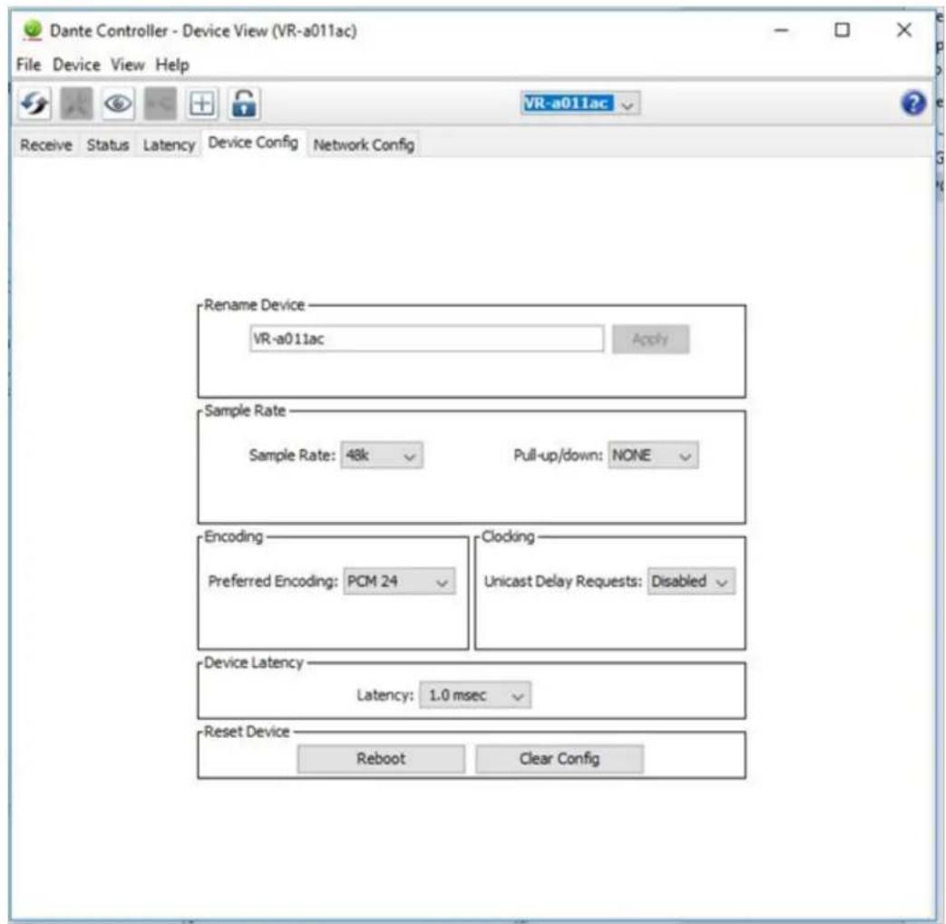
Note: Crest Audio ^® can not provide all the necessary information and data to operate and interface Dante ^® with the Versarray ^™ Pro 112 system in this Owner's Manual. Please visit www.Audinate.com for the detailed information needed. Primers, FAQ's and other basic information on the details of the Dante ^® audio networking system are available.

line
| Frequency [Hz] | dB SPL | | -------------- | ------ | | 12 | 70 | | 150 | 85 | | 200 | 100 | | 300 | 105 | | 400 | 108 | | 500 | 107 | | 600 | 106 | | 700 | 107 | | 800 | 108 | | 900 | 107 | | 1000 | 108 | | 1100 | 107 | | 1200 | 106 |
line
| Frequency [Hz] | Level [dB] | | -------------- | ---------- | | 250 | 3.5 | | 500 | 4.5 | | 1k | 8.0 | | 2k | 12.0 | | 4k | 15.0 | | 8k | 17.0 | | 16k | 18.0 | | 18k | 17.5 |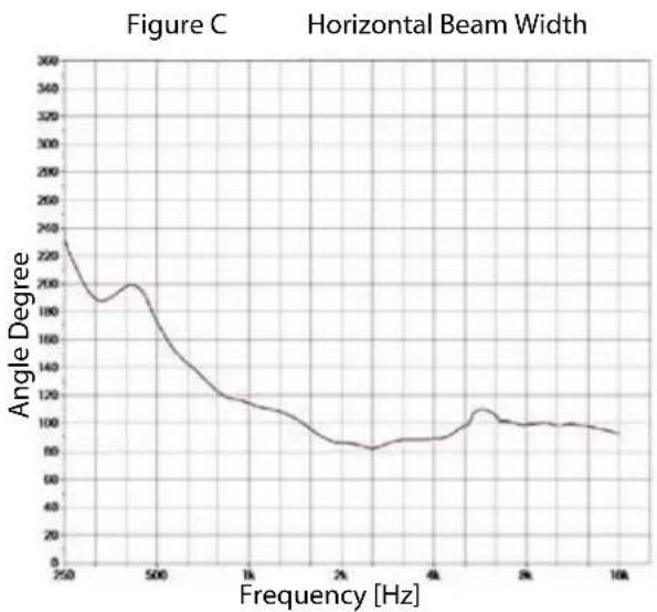
line
| Frequency [Hz] | Angle Degree | | -------------- | ------------ | | 250 | 250 | | 500 | 200 | | 1K | 120 | | 2K | 80 | | 4K | 100 | | 10K | 90 |
line
| Frequency [Hz] | Angle Degree | | -------------- | ------------ | | 250 | 220 | | 500 | 100 | | 750 | 120 | | 1000 | 110 | | 1250 | 80 | | 1500 | 60 | | 1750 | 40 | | 2000 | 30 | | 2250 | 20 | | 2500 | 15 | | 2750 | 10 | | 3000 | 5 | | 3250 | 3 | | 3500 | 2 | | 3750 | 1 | | 4000 | 1 | | 4250 | 1 | | 4500 | 1 | | 4750 | 1 | | 5000 | 1 | | 5250 | 1 | | 5500 | 1 | | 5750 | 1 | | 6000 | 1 | | 6250 | 1 | | 6500 | 1 | | 6750 | 1 | | 7000 | 1 | | 7250 | 1 | | 7500 | 1 | | 7750 | 1 | | 8000 | 1 | | 8250 | 1 | | 8500 | 1 | | 8750 | 1 | | 9000 | 1 | | 9250 | 1 | | 9500 | 1 | | 9750 | 1 | | 10000 | 1 |
radar
| Angle | Frequency Display (Hz) | |-------|------------------------| | 0° | -4 dB | | 30° | -8 dB | | 60° | -12 dB | | 90° | -16 dB | | 120° | -20 dB | | 150° | -24 dB | | 180° | -28 dB | | 210° | -24 dB | | 240° | -20 dB | | 270° | -16 dB | | 300° | -12 dB | | 330° | -8 dB | | 360° | -4 dB |Horizontal Polar Patterns
Frequency: 200Hz (1/3rd Octave)
radar
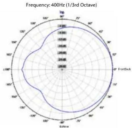
| Direction | Value | | --------- | ------- | | Left | -4.000 | | 120° | -4.000 | | 90° | -4.000 | | 60° | -4.000 | | 30° | -4.000 | | 0° | -4.000 | | 30° | -4.000 | | 60° | -4.000 | | 90° | -4.000 | | 120° | -4.000 | | 90° | -4.000 | | 60° | -4.000 | | 30° | -4.000 | | 0° | -4.000 | | 30° | -4.000 | | | 60° | -4.000 | | 90° | -4.000 | | 120° | -4.000 | | Right | -4.000 | | Left | -4.000 | | 120° | -4.000 | | 90° | -4.000 | | 60° | -4.000 | | 30° | -4.000 | | 0° | -4.000 | | 30° | -4.088 | | 60° | -4.166 | | 90° | -4.254 | | 120° | -4.352 | | Right | -4.352 | | Left | -4.352 | | 120° | -4.352 | | 90° | -4.352 | | 60° | -4.352 | | 30° | -4.352 | | 0° | -4.352 | | 30° | -4.352 | | Right | -4.352 | | Left | -4.352 | | 120° | -4.352 | | 90° | -4.352 | | 60° | -4.352 | | 30° | -4.352 | | 0° } \quad \text{FrontBack}Frequency: 400Hz (1/3rd Octave)
Frequency: 250Hz (1/3rd Octave) Frequency: 315Hz (1/3rd Octave)

radar
| Angle (°) | Value | |---|---| | 0 | 280 | | 30 | 275 | | 60 | 270 | | 90 | 265 | | 120 | 260 | | 150 | 255 | | 180 | 250 | | 210 | 245 | | 240 | 240 | | 270 | 235 | | 300 | 230 | | 330 | 225 | | 360 | 220 | | 390 | 215 | | 420 | 210 | | 450 | 205 | | 480 | 200 | | 510 | 195 | | 540 | 190 | | 570 | 185 | | 600 | 180 | | 630 | 175 | | 660 | 170 | | 690 | 165 | | 720 | 160 | | 750 | 155 | | 780 | 150 | | 810 | 145 | | 840 | 140 | | 870 | 135 | | 900 | 130 | | 930 | 125 | | 960 | 120 | | 990 | 115 | | 1020 | 110 | | 1050 | 105 | | 1080 | 100 | | 1110 | 95 | | 1140 | 90 | | 1170 | 85 | | 1200 | 80 | | 1230 | 75 | | 1260 | 70 | | 1290 | 65 | | 1320 | 60 | | 1350 | 55 | | 1380 | 50 | | 1410 | 45 | | 1440 | 40 | | 1470 | 35 | | 1500 | 30 | | 1530 | 25 | | 1560 | 20 | | 1590 | 15 | | 1620 | 10 | | 1650 | 5 | | 1680 | 0 | | 1710 | -5 | | 1740 | -10 | | 1770 | -15 | | 1800 | -20 | | 1830 | -25 | | 1860 | -30 | | 1890 | -35 | | 1920 | -40 | | 1950 | -45 | | 1980 | -50 | | 2010 | -55 | | 2040 | -60 | | 2070 | -65 | | 2100 | -70 | | 2130 | -75 | | 2160 | -80 | | 2190 | -85 | | 2220 | -90 | | 2250 | -95 | | 2280 | -100 | | 2310 | -105 | | 2340 | -110 | | 2370 | -115 | | 2400 | -120 | | 2430 | -125 | | 2460 | -130 | | 2490 | -135 | | 2520 | -140 | | 2550 | -145 | | 2580 | -150 | | 2610 | -155 | | 2640 | -160 | | 2670 | -165 | | 2700 | -170 | | 2730 | -175 | | 2760 | -180 | | 2790 | -185 | | 2820 | -190 | | 2850 | -195 | | 2880 | -200 | | 2910 | -205 | | 2940 | -210 | | 2970 | -215 | | 3000 | -220 | | 3030 | -225 | | 3060 | -230 | | 3090 | -235 | | 3120 | -240 | | 3150 | -245 | | 3180 | -250 | | 3210 | -255 | | 3240 | -260 | | 3270 | -265 | | 3300 | -270 | | 3330 | -275 | | 3360 | -280 | | 3390 | -285 | | 3420 | -290 | | 3450 | -295 | | 3480 | -300 | | 3510 | -305 | | 3540 | -310 | | 3570 | -315 | | 3600 | -320 | | 3630 | -325 | | 3660 | -330 | | 3690 | -335 | | 3720 | -340 | | 3750 | -345 | | 3780 | -350 | | 3810 | -355 | | 3840 | -360 | | 3870 | -365 | | 3900 | -370 | | 3930 | -375 | | 3960 | -380 | | 3990 | -385 | | Note: The values in the 'Value' column are estimated based on the provided data and are not explicitly labeled in the code. The 'Number' is estimated based on the number of data points. There is no additional data series present in this image. The label 'Number' appears twice in the image: 'Number' has a different value than 'Number'.Frequency: 500Hz (1/3rd Octave)

radar
| Angle (°) | Value | | --------- | ----- | | 0 | 20 | | 30 | 25 | | 60 | 30 | | 90 | 35 | | 120 | 40 | | 150 | 45 | | 180 | 50 | | 210 | 45 | | 240 | 40 | | 270 | 35 | | 300 | 30 | | 330 | 25 | | 360 | 20 |Frequency: 630Hz (1/3rd Octave)

radar
| Angle | Value | |-------|-------| | 0° | 1200 | | 30° | 1300 | | 60° | 1400 | | 90° | 1350 | | 120° | 1250 | | 150° | 1150 | | 180° | 1050 | | 210° | 950 | | 240° | 850 | | 270° | 750 | | 300° | 650 | | 330° | 550 | | 360° | 450 | | 390° | 350 | | 420° | 250 | | 450° | 150 | | 480° | 50 | | 510° | -150 | | 540° | -350 | | 570° | -550 | | 600° | -750 | | 630° | -950 | | 660° | -1150 | | 690° | -1350 | | 720° | -1550 | | 750° | -1750 | | 780° | -1950 | | 810° | -2150 | | 840° | -2350 | | 870° | -2550 | | 900° | -2750 | | 930° | -2950 | | 960° | -3150 | | 990° | -3350 | | Left | -1200 | | Right | -1350 |Frequency: 800Hz (1/3rd Octave)

radar
| Angle | Value | |-------|-------| | 0° | 1200 | | 30° | 1300 | | 60° | 1400 | | 90° | 1350 | | 120° | 1250 | | 150° | 1150 | | 180° | 1050 | | 210° | 950 | | 240° | 850 | | 270° | 750 | | 300° | 650 | | 330° | 550 | | 360° | 450 | | 390° | 350 | | 420° | 250 | | 450° | 150 | | 480° | 50 | | 510° | -150 | | 540° | -350 | | 570° | -550 | | 600° | -750 | | 630° | -950 | | 660° | -1150 | | 690° | -1350 | | 720° | -1550 | | 750° | -1750 | | 780° | -1950 | | 810° | -2150 | | 840° | -2350 | | 870° | -2550 | | 900° | -2750 | | 930° | -2950 | | 960° | -3150 | | 990° | -3350 | | FrontBack | -350 |Frequency: 1000Hz (1/3rd Octave)

radar
| Direction | Value | | --------- | ----- | | Left | 28 | | 90° | 35 | | 130° | 45 | | 160° | 35 | | 190° | 28 | | 220° | 35 | | 250° | 45 | | 280° | 35 | | 310° | 28 | | Right | 35 |Frequency: 1250Hz (1/3rd Octave)
radar
| Angle | Value | |-------|-------| | 0° | 450 | | 30° | 420 | | 60° | 380 | | 90° | 350 | | 120° | 320 | | 150° | 300 | | 180° | 280 | | 210° | 260 | | 240° | 240 | | 270° | 220 | | 300° | 200 | | 330° | 180 | | 360° | 160 |Frequency: 1600Hz (1/3rd Octave)

radar
| Angle | Value | |-------|-------| | 0° | 350 | | 30° | 320 | | 60° | 280 | | 90° | 240 | | 120° | 200 | | 150° | 160 | | 180° | 120 | | 210° | 80 | | 240° | 40 | | 270° | 20 | | 300° | 10 | | 330° | 5 | | 360° | 3 | | 390° | 2 | | 420° | 1 | | 450° | 0.5 | | 480° | 0.3 | | 510° | 0.2 | | 540° | 0.1 | | 570° | 0.05 | | 600° | 0.03 | | 630° | 0.02 | | 660° | 0.01 | | 690° | 0.005 | | 720° | 0.003 | | 750° | 0.002 | | 780° | 0.001 | | 810° | 0.0005| | 840° | 0.0003| | 870° | 0.0002| | 900° | 0.0001| | 930° | 0.0001| | 960° | 0.0001| | 990° | 0.0001| | Left | 35 | | Right | 35 |Frequency: 2000Hz (1/3rd Octave)

Frequency: 2500Hz (1/3rd Octave)

radar
| Angle | Value | |-------|-------| | 0° | 298.00 | | 45° | 148.00 | | 90° | 148.00 | | 135° | 148.00 | | 180° | 148.00 | | 225° | 148.00 | | 270° | 148.00 | | 315° | 148.00 | | 360° | 148.00 |
radar
| Angle | Value | |-------|-------| | 0° | 290.0 | | 30° | 310.0 | | 60° | 320.0 | | 90° | 330.0 | | 120° | 340.0 | | 150° | 350.0 | | 180° | 360.0 | | 210° | 370.0 | | 240° | 380.0 | | 270° | 390.0 | | 300° | 400.0 | | 330° | 410.0 | | 360° | 420.0 | | 390° | 430.0 | | 420° | 440.0 | | 450° | 450.0 |
radar
| Angle | Value | |-------|-------| | 0° | 140 | | 30° | 160 | | 60° | 170 | | 90° | 180 | | 120° | 190 | | 150° | 200 | | 180° | 210 | | 210° | 220 | | 240° | 230 | | 270° | 240 | | 300° | 250 | | 330° | 260 | | 360° | 270 | | 390° | 280 | | 420° | 290 | | 450° | 300 | | 480° | 310 | | 510° | 320 | | 540° | 330 | | 570° | 340 | | 600° | 350 | | 630° | 360 | | 660° | 370 | | 690° | 380 | | 720° | 390 | | 750° | 400 | | 780° | 410 | | 810° | 420 | | 840° | 430 | | 870° | 440 | | 900° | 450 | | 930° | 460 | | 960° | 470 | | 990° | 480 | | Left | -140 | | Right | -160 |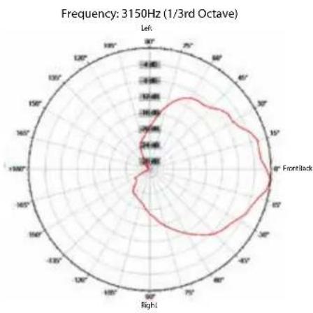
radar
| Angle | Frequency (1/300 Hz) | |-------|----------------------| | 0° | 1200 | | 30° | 1500 | | 60° | 1300 | | 90° | 1400 | | 120° | 1200 | | 150° | 1000 | | 180° | 800 |
radar
| Angle | Frequency | |-------|---------| | 0° | 24.80 | | 30° | 12.60 | | 60° | 9.40 | | 90° | 6.20 | | 120° | 3.00 | | 150° | 1.80 | | 180° | 0.60 | | 210° | -1.20 | | 240° | -2.40 | | 270° | -3.60 | | 300° | -4.80 | | 330° | -6.00 | | 360° | -7.20 | | 390° | -8.40 | | 420° | -9.60 | | 450° | -10.80 | | 480° | -12.00 | | 510° | -13.20 | | 540° | -14.40 | | 570° | -15.60 | | 600° | -16.80 | | 630° | -18.00 | | 660° | -19.20 | | 690° | -20.40 | | 720° | -21.60 | | 750° | -22.80 | | 780° | -24.00 | | 810° | -25.20 | | 840° | -26.40 | | 870° | -27.60 | | 900° | -28.80 | | 930° | -30.00 | | 960° | -31.20 | | 990° | -32.40 | | 1020° | -33.60 | | 1050° | -34.80 | | 1080° | -36.00 | | 1110° | -37.20 | | 1140° | -38.40 | | 1170° | -39.60 | | 1200° | -40.80 | | 1230° | -42.00 | | 1260° | -43.20 | | 1290° | -44.40 | | 1320° | -45.60 | | 1350° | -46.80 | | 1380° | -48.00 | | 1410° | -49.20 | | 1440° | -50.40 | | 1470° | -51.60 | | 1500° | -52.80 | | 1530° | -54.00 | | 1560° | -55.20 | | 1590° | -56.40 | | 1620° | -57.60 | | 1650° | -58.80 | | 1680° | -60.00 | | 1710° | -61.20 | | 1740° | -62.40 | | 1770° | -63.60 | | 1800° | -64.80 | | Note: The data is in a format for frequency estimation based on the given parameters (e.g., 'FuntBack' or 'Left'). The values are estimated based on the provided code output.
radar
| Angle | Frequency | |-------|---------| | 0° | 20 | | 30° | 30 | | 60° | 40 | | 90° | 35 | | 120° | 25 | | 150° | 20 | | 180° | 15 | | 210° | 10 | | 240° | 5 | | 270° | 5 | | 300° | 10 | | 330° | 15 | | 360° | 20 | | 390° | 25 | | 420° | 30 | | 450° | 35 | | 480° | 40 | | 510° | 35 | | 540° | 30 | | 570° | 25 | | 600° | 20 | | 630° | 15 | | 660° | 10 | | 690° | 5 | | 720° | 5 | | 750° | 10 | | 780° | 15 | | 810° | 20 | | 840° | 25 | | 870° | 30 | | 900° | 35 | | 930° | 40 | | 960° | 35 | | 990° | 30 | | Left | - | | Right | - |
radar
| Angle | Value | |-------|-------| | 0° | 2000 | | 45° | 1200 | | 90° | 1400 | | 135° | 1600 | | 180° | 1800 | | 225° | 2000 | | 270° | 1800 | | 315° | 1600 | | 360° | 1400 | | 405° | 1200 | | 450° | 1000 | | 505° | 800 | | 550° | 600 | | 605° | 400 | | 650° | 200 | | 705° | 100 | | 750° | 50 | | 805° | 25 | | 850° | 15 | | 905° | 10 | | 950° | 5 | | 1005° | 2 | | 1050° | 1 | | 1105° | 0.5 | | 1150° | 0.2 | | 1205° | 0.1 | | 1250° | 0.05 | | 1305° | 0.02 | | 1350° | 0.01 | | 1405° | 0.005 | | 1450° | 0.002 | | 1505° | 0.001 | | 1550° | 0.0005| | 1605° | 0.0002| | 1650° | 0.0001| | 1705° | 0.00005| | 1750° | 0.00002| | 1805° | 0.00001| | 1850° | 0.000005| | 1905° | 0.000002| | 2050° | 0.000001| | Note: The 'FrontBack' label indicates the value for the outermost axis (Left) and the rest of the outermost axis (Right). The 'Left' label is not explicitly labeled on the chart but appears to be part of the data series. The 'Right' label is not explicitly labeled on the chart but corresponds to the position of the outermost axis on the x-axis. The 'Left' label is not explicitly labeled on the chart but corresponds to the y-axis label on the left. The 'Center' label is also displayed on the chart.
radar
| Angle | Frequency | |-------|---------| | 0° | 12000 | | 30° | 13500 | | 60° | 14000 | | 90° | 13000 | | 120° | 11500 | | 150° | 10000 | | 180° | 9500 | | 210° | 9000 | | 240° | 8500 | | 270° | 8000 | | 300° | 7500 | | 330° | 7000 | | 360° | 6500 | | 390° | 6000 | | 420° | 5500 | | 450° | 5000 | | 480° | 4500 | | 510° | 4000 | | 540° | 3500 | | 570° | 3000 | | 600° | 2500 | | 630° | 2000 | | 660° | 1500 | | 690° | 1000 | | 720° | 500 | | 750° | 250 | | 780° | 125 | | 810° | 87 | | 840° | 62 | | 870° | 46 | | 900° | 31 | | 930° | 22 | | 960° | 14 | | 990° | 8 | | Left | - | | Right | - |
radar
| Direction | Frequency | | --------- | --------- | | Left | 0 | | 90° | 14000 | | 75° | 12000 | | 60° | 10000 | | 45° | 8000 | | 30° | 6000 | | 15° | 4000 | | -15° | 2000 | | -30° | 1000 | | -45° | 500 | | -60° | 250 | | -75° | 100 | | -90° | 50 | | -105° | 25 | | -120° | 10 | | -135° | 5 | | -150° | 2 | | -165° | 1 | | -180° | 0 | | -200° | 0 | | -225° | 0 | | -250° | 0 | | -275° | 0 | | -300° | 0 | | -325° | 0 | | -350° | 0 | | -375° | 0 | | -400° | 0 | | -425° | 0 | | -450° | 0 | | -475° | 0 | | -500° | 0 | | -525° | 0 | | -550° | 0 | | -575° | 0 | | -600° | 0 | | -625° | 0 | | -650° | 0 | | -675° | 0 | | -700° | 0 | | -725° | 0 | | -750° | 0 | | -775° | 0 | | -800° | 0 | | -825° | 0 | | -850° | 0 | | -875° | 0 | | -900° | 0 | | -925° | 0 | | -950° | 0 | | -975° | 0 | | -1000° | 0 | | -1025° | 0 | | -1050° | 0 | | -1075° | 0 | | -1100° | 0 | | -1125° | 0 | | -1150° | 0 | | -1175° | 0 | | -1200° | 0 | | -1225° | 0 | | -1250° | 0 | | -1275° | 0 | | -1300° | 0 | | -1325° | 0 | | -1350° | 0 | | -1375° | 0 | | -1400° | 0 | | -1425° | 0 | | -1450° | 0 | | -1475° | 0 | | -1500° | 0 | | -1525° | 0 | | -1550° | 0 | | -1575° | 0 | | -1600° | 0 | | -1625° | 0 | | -1650° | 0 | | -1675° | 0 | | -1700° | 0 | | -1725° | 0 | | -1750° | 0 | | -1775° | 0 | | -1800° | 0 | | -1825° | 0 | | -1850° | 0 | | -1875° | 0 | | -1900° | 0 | | -1925° | 0 | | -1950° | 0 | | -1975° | 0 | | -2000° | 0 | | -2025° | 0 | | -2050° | 0 | | -2075° | 0 | | -2100° | 0 | | -2125° | 0 | | -2150° | 0 | | -2175° | 0 | | -2200° | 0 | | -2225° | 0 | | -2250° | 0 | | -2275° | 0 | | -2300° | 0 | | -2325° | 0 | | -2350° | 0 | | -2375° | 0 | | -2400° | 0 | | -2425° | 0 | | -2450° | 0 | | -2475° | 0 | | -2500° | 0 | | -2525° | 0 | | -2550° | 0 | | -2575° | 0 | | -2600° | 0 | | -2625° | 0 | | -2650° | 0 | | -2675° | 0 | | -2700° | 0 | | -2725° | 0 | | -2750° | 0 | | -2775° | 0 | | -2800° | 0 | | -2825° | 0 | | -2850° | 0 | | -2875° | 0 | | -2900° | 0 | | -2925° | 0 | | -2950° | 0 | | -2975° | 0 | | -313.3 | nan |
radar
| Angle | Value | |-------|-------| | 0° | 1400 | | 30° | 1500 | | 60° | 1600 | | 90° | 1700 | | 120° | 1800 | | 150° | 1900 | | 180° | 2000 | | 210° | 2100 | | 240° | 2200 | | 270° | 2300 | | 300° | 2400 | | 330° | 2500 | | 360° | 2600 | | 390° | 2700 | | 420° | 2800 | | 450° | 2900 | | 480° | 3000 | | 510° | 3100 | | 540° | 3200 | | 570° | 3300 | | 600° | 3400 | | 630° | 3500 | | 660° | 3600 | | 690° | 3700 | | 720° | 3800 | | 750° | 3900 | | 780° | 4000 | | 810° | 4100 | | 840° | 4200 | | 870° | 4300 | | 900° | 4400 | | 930° | 4500 | | 960° | 4600 | | 990° | 4700 | | Left | - | | Right | - |Frequency Display: Hz (1/3rd Octave)
radar
| Direction | Value (dB) | | --------- | ---------- | | Top | -4 | | Front | -8 | | Bottom | -12 | | Back | -16 | | Top | -20 | | Front | -24 | | Bottom | -28 |Vertical Polar Patterns

radar
| Angle | Value | |-------|--------| | 0° | 5.48 | | 30° | 5.48 | | 60° | 5.48 | | 90° | 5.48 | | 120° | 5.48 | | 150° | 5.48 | | 180° | 5.48 | | 210° | 5.48 | | 240° | 5.48 | | 270° | 5.48 | | 300° | 5.48 | | 330° | 5.48 | | 360° | 5.48 |
radar
| Angle | Value | |-------|--------| | 0° | 24.48 | | 30° | 24.48 | | 60° | 24.48 | | 90° | 24.48 | | 120° | 24.48 | | 150° | 24.48 | | 180° | 24.48 | | 210° | 24.48 | | 240° | 24.48 | | 270° | 24.48 | | 300° | 24.48 | | 330° | 24.48 | | 360° | 24.48 |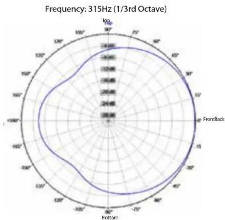
radar
| Angle | Value | |-------|-------| | 0° | 28.00 | | 30° | 45.00 | | 60° | 54.00 | | 90° | 45.00 | | 120° | 28.00 | | 150° | 45.00 | | 180° | 54.00 | | 210° | 45.00 | | 240° | 28.00 | | 270° | 45.00 | | 300° | 54.00 | | 330° | 45.00 | | 360° | 28.00 |
radar
| Angle | Value | |-------|--------| | 0° | 24.48 | | 30° | 24.48 | | 60° | 24.48 | | 90° | 24.48 | | 120° | 24.48 | | 150° | 24.48 | | 180° | 24.48 | | 210° | 24.48 | | 240° | 24.48 | | 270° | 24.48 | | 300° | 24.48 | | 330° | 24.48 | | 360° | 24.48 |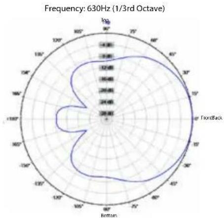
radar
| Angle | Value | |-------|-------| | 0° | 28.85 | | 30° | 24.45 | | 60° | 18.45 | | 90° | 12.45 | | 120° | 8.45 | | 150° | 4.45 | | 180° | 2.45 | | 210° | 0 | | 240° | 2.45 | | 270° | 4.45 | | 300° | 6.45 | | 330° | 8.45 | | 360° | 10.45 |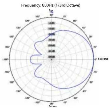

radar
| Angle | Value | |-------|-----------| | 0° | 12.5 | | 30° | 14.0 | | 60° | 13.5 | | 90° | 12.0 | | 120° | 11.5 | | 150° | 10.5 | | 180° | 9.5 | | 210° | 8.5 | | 240° | 7.5 | | 270° | 6.5 | | 300° | 5.5 | | 330° | 4.5 | | 360° | 3.5 | | 390° | 2.5 | | 420° | 1.5 | | 450° | 0.5 | | 480° | -0.5 | | 510° | -1.5 | | 540° | -2.5 | | 570° | -3.5 | | 600° | -4.5 | | 630° | -5.5 | | 660° | -6.5 | | 690° | -7.5 | | 720° | -8.5 | | 750° | -9.5 | | 780° | -10.5 | | 810° | -11.5 | | 840° | -12.5 | | 870° | -13.5 | | 900° | -14.5 | | 930° | -15.5 | | 960° | -16.5 | | 990° | -17.5 | | Top | -12.5 | | Frontlack | -14.0 | | Bottom | -16.5 |
radar
| Angle | Frequency | |-------|---------| | Top | 4.00 | | 90° | 3.50 | | 60° | 3.00 | | 30° | 2.50 | | 0° | 2.00 | | -30° | 1.50 | | -60° | 1.00 | | -90° | 0.50 | | -120° | 0.00 | | -150° | -0.50 | | -180° | -1.00 | | -210° | -1.50 | | -240° | -2.00 | | -270° | -2.50 | | -300° | -3.00 | | -330° | -3.50 | | -360° | -4.00 | | -390° | -3.50 | | -420° | -3.00 | | -450° | -2.50 | | -480° | -2.00 | | -510° | -1.50 | | -540° | -1.00 | | -570° | -0.50 | | -600° | 0.00 | | -630° | 0.50 | | -660° | 1.00 | | -690° | 1.50 | | -720° | 2.00 | | -750° | 2.50 | | -780° | 3.00 | | -810° | 3.50 | | -840° | 4.00 | | -870° | 3.50 | | -900° | 3.00 | | -930° | 2.50 | | -960° | 2.00 | | -990° | 1.50 | | -1020°| 1.00 | | -1050°| 0.50 | | -1080°| 0.00 | | -1110°| -0.50 | | -1140°| -1.00 | | -1170°| -1.50 | | -1200°| -2.00 | | -1230°| -2.50 | | -1260°| -3.00 | | -1290°| -3.50 | | -1320°| -4.00 | | -1350°| -3.50 | | -1380°| -3.00 | | -1410°| -2.50 | | -1440°| -2.00 | | -1470°| -1.50 | | -1500°| -1.00 | | -1530°| -0.50 | | -1560°| 0.00 | | -1590°| 0.50 | | -1620°| 1.00 | | -1650°| 1.50 | | -1680°| 2.00 | | -1710°| 2.50 | | -1740°| 3.00 | | -1770°| 3.50 | | -1800°| 4.00 | | -1830°| 3.50 | | -1860°| 3.00 | | -1890°| 2.50 | | -1920°| 2.00 | | -1950°| 1.50 | | -1980°| 1.00 | | -2010°| 0.50 | | -2040°| 0.0 |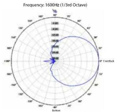
radar
| Angle | Value | |-------|--------| | Top | 0 | | 90° | 24 | | 75° | 24 | | 60° | 24 | | 45° | 24 | | 30° | 24 | | FrontBack | 24 | | Bottom | 24 |
radar
| Angle | Frequency | |-------|---------| | 0° | 14.80 | | 45° | 12.70 | | 90° | 10.50 | | 135° | 8.20 | | 180° | 6.80 | | 225° | 5.50 | | 270° | 4.20 | | 315° | 3.00 | | 360° | 2.00 | | 405° | 1.50 | | 450° | 1.00 | | 505° | 0.80 | | 550° | 0.60 | | 605° | 0.40 | | 650° | 0.30 | | 705° | 0.20 | | 750° | 0.15 | | 805° | 0.10 | | 850° | 0.08 | | 905° | 0.06 | | 950° | 0.04 | | 1005° | 0.03 | | 1050° | 0.02 | | 1105° | 0.01 | | 1150° | 0.01 | | 1205° | 0.01 | | 1250° | 0.01 | | 1305° | 0.01 | | 1350° | 0.01 | | 1405° | 0.01 | | 1450° | 0.01 | | 1505° | 0.01 | | 1550° | 0.01 | | 1605° | 0.01 | | 1650° | 0.01 | | 1705° | 0.01 | | 1750° | 0.01 | | 1805° | 0.01 | | 1850° | 0.01 | | 1905° | 0.01 | | 2050° | 0.38 | | FrontBack | - |
radar
| Angle | Value | |-------|--------| | Top | 1.00 | | 90° | 1.00 | | 80° | 1.00 | | 70° | 1.00 | | 60° | 1.00 | | 50° | 1.00 | | 40° | 1.00 | | 30° | 1.00 | | 20° | 1.00 | | 10° | 1.00 | | 0° | 1.00 | | -10° | 1.00 | | -20° | 1.00 | | -30° | 1.00 | | -40° | 1.00 | | -50° | 1.00 | | -60° | 1.00 | | -70° | 1.00 | | -80° | 1.00 | | -90° | 1.00 | | -100° | 1.00 | | -110° | 1.00 | | -120° | 1.00 | | -130° | 1.00 | | -140° | 1.00 | | -150° | 1.00 | | -160° | 1.00 | | -170° | 1.00 | | -180° | 1.00 | | -190° | 1.00 | | -200° | 1.00 | | -210° | 1.00 | | -220° | 1.00 | | -230° | 1.00 | | -240° | 1.00 | | -250° | 1.00 | | -260° | 1.00 | | -270° | 1.00 | | -280° | 1.00 | | -290° | 1.00 | | -300° | 1.00 | | -310° | 1.00 | | -320° | 1.00 | | -330° | 1.00 | | -340° | 1.00 | | -350° | 1.00 | | -360° | 1.00 | | -370° | 1.00 | | -380° | 1.00 | | -390° | 1.00 | | -400° | 1.00 | | -410° | 1.00 | | -420° | 1.00 | | -430° | 1.00 | | -440° | 1.00 | | -450° | 1.00 | | -460° | 1.00 | | -470° | 1.00 | | -480° | 1.00 | | -490° | 1.00 | | -500° | 1.00 | | -510° | 1.00 | | -520° | 1.00 | | -530° | 1.00 | | -540° | 1.00 | | -550° | 1.00 | | -560° | 1.00 | | -570° | 1.00 | | -580° | 1.00 | | -590° | 1.00 | | -600° | 1.00 | | -610° | 1.00 | | -620° | 1.00 | | -630° | 1.00 | | -640° | 1.00 | | -650° | 1.00 | | -660° | 1.00 | | -670° | 1.00 | | -680° | 1.00 | | -690° | 1.00 | | -700° | 1.00 | | -710° | 1.00 | | -720° | 1.00 | | -730° | 1.00 | | -740° | 1.00 | | -750° | 1.00 | | -760° | 1.00 | | -770° | 1.00 | | -780° | 1.00 | | -790° | 1.00 | | -800° | 1.00 | | -810° | 1.58 | | -825° | 2.58 | | -845° | 4.58 | | -865° | 6.58 | | -885° | 8.58 | | -915° | 9.58 | | -945° | 9.58 | | -975° | 9.58 | | -995° | 9.58 | | -999% | 9.58 | | -999%+ | 9.58 |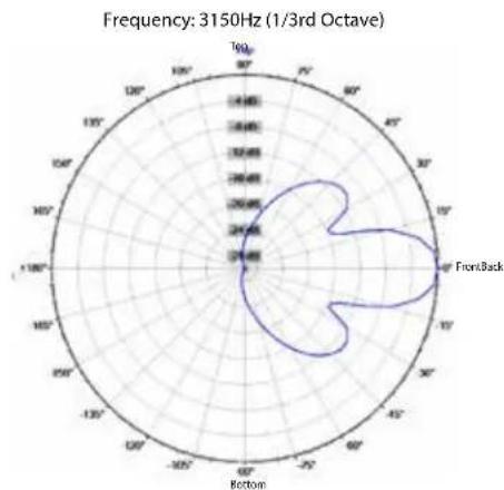

radar
| Angle | Frequency | |-------|---------| | 0° | 270 | | 40° | 290 | | 80° | 260 | | 120° | 240 | | 160° | 230 | | 200° | 220 | | 240° | 210 | | 280° | 200 | | 320° | 190 | | 360° | 180 |
radar
| Angle | Frequency (Hz) | |-------|----------------| | 0° | 24000 | | 30° | 24000 | | 60° | 24000 | | 90° | 24000 | | 120° | 24000 | | 150° | 24000 | | 180° | 24000 | | 210° | 24000 | | 240° | 24000 | | 270° | 24000 | | 300° | 24000 | | 330° | 24000 | | 360° | 24000 |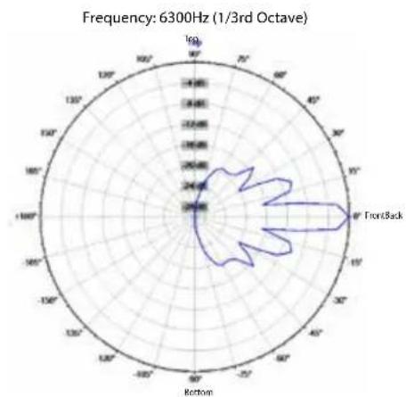
radar
| Angle | Value | |-------|-------| | 0° | 2400 | | 90° | 2400 | | 180° | 2400 | | 270° | 2400 | | 360° | 2400 |
radar
| Angle | Value | |-------|-------| | 0° | 29.64 | | 30° | 29.64 | | 60° | 29.64 | | 90° | 29.64 | | 120° | 29.64 | | 150° | 29.64 | | 180° | 29.64 | | 210° | 29.64 | | 240° | 29.64 | | 270° | 29.64 | | 300° | 29.64 | | 330° | 29.64 | | 360° | 29.64 | | 390° | 29.64 | | 420° | 29.64 | | 450° | 29.64 | | 480° | 29.64 | | 510° | 29.64 | | 540° | 29.64 | | 570° | 29.64 | | 600° | 29.64 | | 630° | 29.64 | | 660° | 29.64 | | 690° | 29.64 | | 720° | 29.64 | | 750° | 29.64 | | 780° | 29.64 | | 810° | 29.64 | | 840° | 29.64 | | 870° | 29.64 | | 900° | 29.64 | | 930° | 29.64 | | 960° | 29.64 | | 990° | 29.64 | | 1020° | 29.64 | | 1050° | 29.64 | | 1080° | 29.64 | | 1110° | 29.64 | | 1140° | 29.64 | | 1170° | 29.64 | | 1200° | 29.64 | | 1230° | 29.64 | | 1260° | 29.64 | | 1290° | 29.64 | | 1320° | 29.64 | | 1350° | 29.64 | | 1380° | 29.64 | | 1410° | 29.64 | | 1440° | 29.64 | | 1470° | 29.64 | | 1500° | 29.64 | | 1530° | 29.64 | | 1560° | 29.64 | | 1590° | 29.64 | | 1620° | 29.64 | | 1650° | 29.64 | | 1680° | 29.64 | | 1710° | 29.64 | | 1740° | 29.64 | | 1770° | 29.64 | | 1800° | 29.64 | | Note: The data is extracted from the provided image as it is not fully visible in the chart type of the data series. The values are estimated based on the given code format (e.g., "FrontBack").
radar
| Angle | Value | |-------|-------| | Top | 20V | | 90° | 25V | | 75° | 24V | | 60° | 23V | | 45° | 22V | | 30° | 21V | | 15° | 20V | | 5° | 19V | | 0° | 18V | | -5° | 17V | | -10° | 16V | | -15° | 15V | | -20° | 14V | | -25° | 13V | | -30° | 12V | | -35° | 11V | | -40° | 10V | | -45° | 9V | | -50° | 8V | | -55° | 7V | | -60° | 6V | | -65° | 5V | | -70° | 4V | | -75° | 3V | | -80° | 2V | | -85° | 1V | | -90° | 0.5V | | -95° | 0.3V | | -100° | 0.2V | | -105° | 0.1V | | -110° | 0.05V | | -115° | 0.03V | | -120° | 0.02V | | -125° | 0.01V | | -130° | 0.005V| | -135° | 0.003V| | -140° | 0.002V| | -145° | 0.001V| | -150° | 0.0005V| | -155° | 0.0003V| | -160° | 0.0002V| | -165° | 0.0001V| | -170° | 0.00005V| | -175° | 0.00003V| | -180° | 0.00002V| | -185° | 0.00001V| | -190° | 0.000005V| | -195° | 0.000003V| | -200° | 0.000002V| | -205° | 0.000001V| | -210° | 0.0000005V| | -215° | 0.0000003V| | -220° | 0.0000002V| | -225° | 0.0000001V| | -230° | 0.00000005V| | -235° | 0.00000003V| | -240° | 0.00000002V| | -245° | 0.00000001V| | -250° | 0.000000005V| | -255° | 0.000000003V| | -260° | 0.000000002V| | -265° | 0.000000001V| | -270° | 0.0000000005V| | -275° | 0.0000000003V| | -280° | 0.0000000002V| | -285° | 0.0000000001V| | -290° | 0.0000000001V| | -295° | 66.676 | | -365° | nan | | FrontBack | (labeled as "FrontBack")Frequency: 12500Hz (1/3rd Octave)

radar
| Direction | Value | | --------- | ----- | | Top | 24.00 | | Top/Back | 24.00 | | Bottom | 24.00 | | Bottom-Back | 24.00 |Frequency: 16000Hz (1/3rd Octave)

radar
| Direction | Value | |---|---| | Top | -19.5 | | 90° | -17.8 | | 75° | -16.2 | | 60° | -14.5 | | 45° | -12.8 | | 30° | -11.2 | | 15° | -9.5 | | 5° | -7.8 | | Frontback | 24.88 | | 15° | 23.5 | | 30° | 22.0 | | 45° | 20.5 | | 60° | 19.0 | | 75° | 17.5 | | 90° | 16.0 | | Bottom | 14.5 |Ribbon Tweeter Warnings and Cautions
CAUTION! Ribbon Tweeters do not exhibit audible signs of distress when overloaded! It is possible to exceed the physical and/or thermal limits by overloading the unit suddenly with excess power, even though there are no obvious sounds of distress.
CAUTION! In order to prevent damage to the ribbon tweeters, keep the Versarray™ Pro 112 system away from metal filings at all times. Do not expose ribbons to blasts of air, and do not use canned air to spray the ribbons, as this can result in damage. Do not expose ribbons to liquids or caustic fumes, and keep away from salt spray.
Frequency Response
This measurement is useful in determining how accurately a given unit reproduces an input signal. The frequency response of the Versarray ^™ Pro 112 is measured at a distance of 1 meter using a swept-sine input signal. As shown in Figure A, the selected drivers in the Versarray ^™ Pro 112 combine to give a smooth frequency response with the built-in signal processing.
Directivity
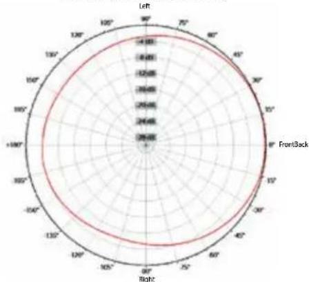
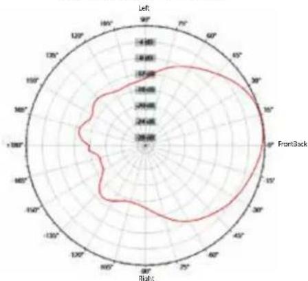
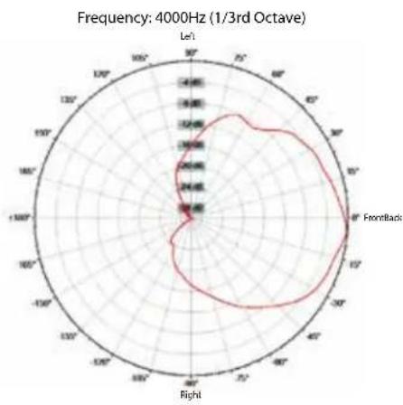
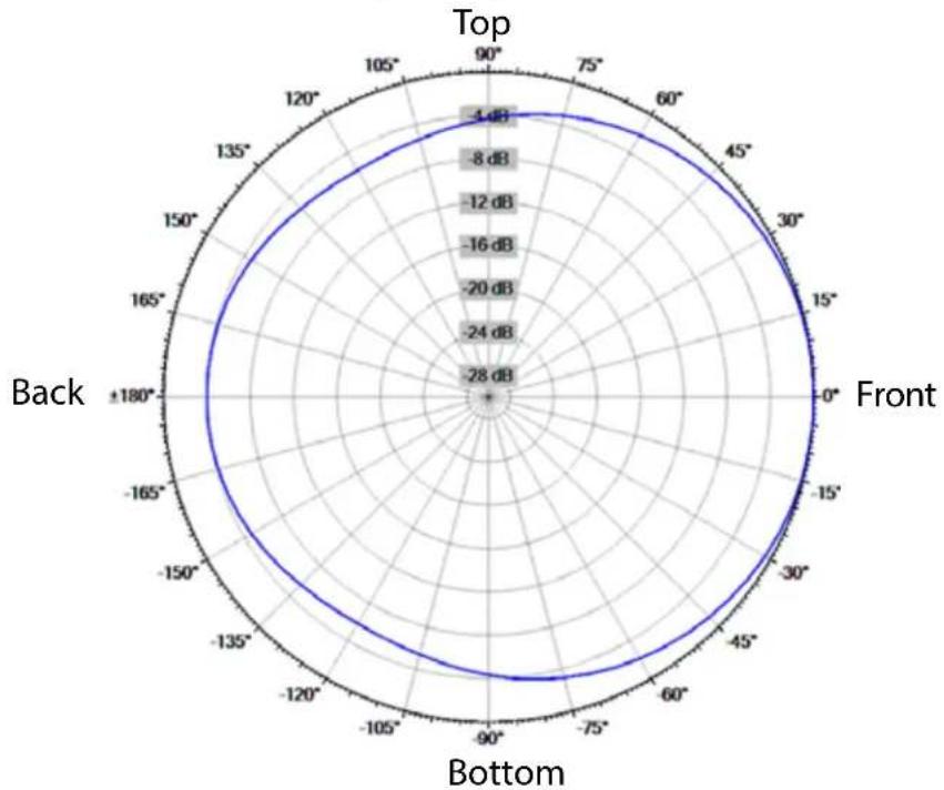
Beamwidth is derived from the -6 dB points from the polar plots which are measured in a whole space anechoic environment. Q and Directivity Index are plotted for the on-axis measurement position. These are specifications that provide a reference to the coverage characteristics of the unit. These parameters provide insight for proper placement and installation in the chosen environment. The blending of the components of the Versarray™ Pro 112 and the DSP Presets exhibit a desirable beamwidth and directivity (as shown in Figures B, C and D) suitable for sound reinforcement applications.
Crest Audio ^® MLAS ^™ technique
The next section of the Owner's manual deals with the Crest Audio® MLAS™ technique, or the Modular Line Array System™ method of building up a line array configuration using basic building blocks of Presets and line array segments.
What is the MLAS ^™ technique, or the Modular Line Array System ^™ ? It is a line array configuration design technique that rests on over 15 years of research into line array behavior, and the ensuing field feedback and experiences that have occurred in that time frame as well. Rather than just take some of the well worn myths about line arrays at face value, or accept rules of thumb as gospel, the full range and gamut of line array behavior was examined, measured, tested and refined to the point where the implementation of typical line array geometries was able to be simplified and codified.
The end user now has the option of selecting pre-engineered Presets that match with specific modular line array sections, and using these modules to build a line array geometry that is most applicable to their particular situation, without the requirement to delve into time consuming and difficult simulations or modeling software. In fact, if the user so desires, they can still perform their modeling and simulations, and still reap the benefits of well engineered Presets ready to use for any given set of line array modular segmented “paste-ups”.
The Crest Audio ^® MLAS ^™ technique, specifically is a method of breaking any line array vertical geometrical configuration down into defined segments of line array EQ that are appropriate for that segments contribution to the overall array output. Rather than treat each line array geometry as a singularly unique set of cabinet angles and EQ for each individual cabinet (or for the system as a whole), line array segments that share a common trait, such as all the same angle between cabinets, all being used in a Long Throw mode, etc., are broken out as a cluster of cabinets separated from the other differing segments of the array.
An EQ Preset is created that addresses specifically that cluster or segment of cabinets, and the conditions they are operating under. This provides a set of typical line array vertical geometry configurations that can be assembled with several different operational modules consisting of that cluster of cabinets, and the specific EQ needed for their correct operation.
The Versarray™ Pro 112 system can hang as many as 15 cabinets, and if a separate EQ was generated for all the variations that 15 cabinets with 7 different vertical angles between cabinets can have, it would amount to thousands of possible array geometry configurations. By breaking the vertical array geometry down into the fundamental geometry segments most likely to be used and implemented, we now limit the number of EQ Presets to about 40 or so for the MLAS™ technique. About half of those are variations on the primary EQ modules, that provide either a Bass Boost mode of operation, or some Long Throw EQ for those geometries that would actually be used for LT purposes.
Note that the Horizontal coverage of the Versarray ^™ Pro 112 is nominally 90 degrees, and thus, the array should be aimed horizontally using the rotation of the Halo to cover the 90 degrees desired. Front to back location as well as height can be used to help tune this horizontal coverage, as well as allow for adjustment of the vertical coverage as well.
The module categories we have provided cover all the typical, traditional and advanced line array geometries that would be used in the real world.
Those categories are:
Straight line geometry - used primarily for Long Throw purposes, thus these Presets don't need a separate LT version. 0 degrees between cabinets.
Mild Angle - used for Long to Medium Throw coverage or specific angles of closer coverage. 2.5 to 5 degrees between cabinets.
More Angled - used for Medium to Short Throw coverage or specific angles of closer coverage. 7.5 to 10
degrees between cabinets.
J-line section - used for acute angled segments, as typically implemented in the bottom portion of classic J-line geometry. 12.5 to 15 degrees between cabinets.
See MLAS™ Example 1 diagram

Part 1
Selecting the Line Array Geometry
Classic line arrays used a simple straight line geometry, this provides the classic “laser beam” vertical coverage pattern that has become associated with line arrays today. However, many do not realize that the vertical coverage pattern is extremely tight and limited, typically not extending vertically past the ends of the array at a distance.
Laboratory measurements of the amount of angular coverage are not that accurate with straight line arrays, because the effective coverage angle keeps getting smaller as you get further and further away, until it may be just a fraction of a degree at some very far distance.
The upshot of this is that unless you truly need the extremely tight vertical coverage pattern AND can successfully aim the entire array at the exact spot you wish to cover, a classic straight line geometry is not going to be the best choice. A more useful and general-purpose geometry is a gentle and continuous curve, with the angle between each cabinet a total of 2.5 degrees. This would provide approximately 16 degrees of seamless vertical coverage with a 6 cabinet array, and maintain a fairly smooth frequency response. With the Versarray™ Pro 112, this creates a system with a coverage pattern of approximately 90 degrees horizontal and 16 degrees vertical.
If the venue is smaller or needs a more open vertical pattern for coverage, then there are several options that can address this. You can increase the angle between all the 6 cabinets to 5 degrees total, providing a vertical coverage of approx. 30 degrees.
If that is too much vertical coverage, but there are still some seats up front that need to be covered, then there are two other recommended geometries to use. One is a dual radius, as pioneered by Peavey on the Peavey SSE™-LA. The upper three cabinets would be set to a total angle between cabinets of 2.5 degrees, while the bottom
three would be set to 5 degrees. This arrangement provides a smooth, seamless vertical coverage pattern of approximately 22 degrees.
The other geometry is a modification of the classic “J” line, using a continuously curved array for the top section instead of a straight line, and then an abruptly curved section for the bottom few cabinets. This might consist of the top four or five cabinets angled at 2.5 and 5 degrees, with the bottom one or two each angled more drastically at 12.5 or 15 degrees. Up till now, we have been talking about a relatively smooth vertical coverage, with no gaps or suck-outs in the vertical pattern. However, the use of the “J” precludes this due to the sharper angles between the individual bottom cabinets. Anything over about 5 degrees total angle between cabinets will tend to cause a “gap’ or a “hole” in the response at certain frequencies, and while it is not too bad, the sharper the angle, the worse it gets.
Why not use a classic “J” line geometry? This combines the narrow “laser beam” pattern with a “gaps in the coverage” pattern, sort of the worst of both worlds. This is why we recommend one form or another of a gentle and continuous curve, to avoid these common problems, and provide maximum performance.
Note that this behavior of a “gap” or a “hole” in the response at certain frequencies is not exclusive to the Versarray™ Pro 112 system, this occurs with many other brands and models of line array cabinets. If special attention is paid to the vertical behavior of the individual cabinets and how they interface as an array, then this kind of behavior can be minimized. Certain “fixed curve” line array modules are on the market, and while they do provide a relatively smooth coverage for their intended angle, the geometry is fixed, and does not allow any adjustment past the fixed angle in use.
Due to the wider vertical coverage, you are often limited to using only two of these modules, before the third module is pointing nearly straight down. Thus, the number of array elements is severely limited, and the ability to use a gentler angle or a straight line segment is not an option.
What Constitutes a "Real" Line Array?
Even though the individual Versarray™ Pro 112 cabinets have a line array tweeter section, one Versarray™ Pro 112 cabinet is not a line array all by itself. In order to benefit from a significant amount of line array behavior, you need at least 4 cabinets arrayed together vertically. This is not to say that the use of just two or three Versarray™ Pro 112 cabinets is not possible, but the unique strengths of a line array don't come into play until you get enough cabinets to work together to create that line array wave launch across a wide band of frequencies, all the way down into the mid-bass. It is strongly recommended that four or more Versarray™ Pro 112 cabinets be used together in a single array hang for this reason.
Aiming the Line Array
If a classic straight line array geometry is used, then aiming becomes critical; the coverage pattern at high frequencies is only going to be about 10 feet tall for a set of eight Versarray 112 cabinets at a very long distance. You will have to pick the 10 feet or so of vertical space you want covered very carefully, and aim the array precisely. Here, use of an inexpensive laser pointer temporarily taped to the top and/or bottom of the array can be an invaluable aiming aid.
If you have chosen one of the geometries that provide a smooth curvature and a relatively narrow vertical coverage, then aiming will be more in line with the kinds of concerns and methods used for high Q point sources when looked at in one dimension, but you still have to pay attention to assuring that seating areas of primary concern are within that pattern.
If you have chosen one of the dual radius curvatures, the top section will be handling the long throw vertical coverage, and the bottom section will be providing the medium/short throw vertical coverage. Once again, use of
the familiar tools for aiming point sources and clusters will be helpful here, as long as you realize that you have two different coverage zones.
Crest Audio ^® has teamed with EASE ^® Focus 3 software to bring you line array aiming software with the Versarray ^™ Pro 112 system included in the database. Check with your Crest Audio ^® representative, or visit the Crest Audio ^® web site for more information. https://peaveycommercialaudio.com/versarray
The EASE* Focus 3 program can be found at: http://focus.afmg.eu/index.php/fc-downloads-en.html
Example of Using the MLAS™ Technique
As a working example of the MLAS™ technique, let's construct a line array configuration that has a specific use. The venue we need to cover has a significant amount of balcony seating further away from the line, and then, more conventional seating nearer to the line on a floor plan. Eight Versarray™ Pro 112 cabinets are to be used for this line array
See MLAS Example 2 (NOTE: Diagram is not to scale, used for example only)
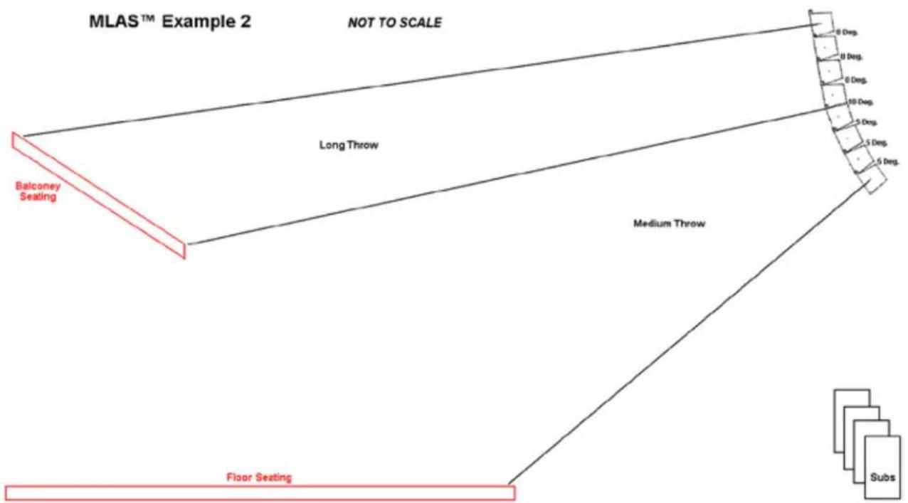
This line array could consist of a vertical coverage arrangement including a Straight line segment to cover the balcony, and a Mild Angle segment for the floor seating.
In this instance, a segment consisting of 4 cabinets programmed with the 4cabs_Straight-line Preset is used to cover the balcony, and a segment consisting of 4 cabinets programmed with 4Cabs_Mild_Angle Preset is used to cover the floor.
In another example, we create a dual-radius curvature line array using 8 Versarray™ Pro 112 cabinets. This configuration is a very useful and somewhat universal line array configuration, and so, makes a good example to
use to explain the MLAS™ process and the end results.
If we look down at the list of coverage angles provided by the various Presets available to be used (See list below this section), we are going to use the LT_4Cabs_Mild_Angle Preset for
the top 4 cabinets, and use the 4Cabs_Mild_Angle Preset for the bottom 4 cabinets
We will designate the top cabinet at zero degrees relative to the Halo. The Halo can be angled up to 25 degrees, so as to aim the array at the target audience.
Then the next three cabinets get angled at 2.5 degrees relative to each other, and the bottom four angled at 5 degrees relative to each other.
See MLAS™ Example 3

Vertical Coverage Angles of Various Section Presets
Preset: Single\_Cab\_Flat
One Versarray ^™ Pro 112 Cabinet - 15 degrees nominal, but narrows down as the distance from the cabinet gets greater. Used as a reference point, as well as for use of an isolated Versarray ^™ Pro 112 Cabinet without arraying a number of cabinets.
Preset: 2cabs\_Straight-line
Two VR112 Cabinets Straight - 8 degrees nominal, but narrows down as the distance from the cabinet gets greater.
Preset: 2Cabs_Mild_Angle
Two VR112 Cabinets @ 2.5 degrees total angle between cabinets - 7 degrees, but tends to stay the same as distance increases.
Preset: 2Cabs_Mild_Angle
Two VR112 Cabinets @ 5 degrees - 9 degrees, but tends to stay the same as distance increases.
Note 1: Vertical High Frequency coverage is no longer a continuous spread when the angle between cabinets exceeds 5 degrees. Angles of more than 5 degrees between cabinets are considered special cases.
Preset: 3cabs_Straight-line
Three VR112 Cabinets Straight - 5 degrees, but narrows down as the distance from the cabinets gets greater.
Preset: 3Cabs_Mild_Angle
Three VR112 Cabinets @ 2.5 degrees - 9 degrees, but tends to stay the same as distance increases.
Preset: 3Cabs_Mild_Angle
Three VR112 Cabinets @ 5 degrees - 14 degrees, but remains the same as distance increases.
See Note 1
Preset: 4cabs_Straight-line
Four VR112 Cabinets Straight - 4 degrees, but narrows down as the distance from the cabinets gets greater.
Preset: 4Cabs_Mild_Angle
Four VR112 Cabinets @ 2.5 degrees - 12 degrees, but tends to stay the same as distance increases.
Preset: 4Cabs_Mild_Angle
Four VR112 Cabinets @ 5 degrees - 20 degrees, but remains the same as distance increases.
See Note 1
Preset: 6cabs_Straight-line
Six VR112 Cabinets Straight - 3 degrees, but narrows down as the distance from the cabinets gets even greater.
Preset: 6Cabs_Mild_Angle
Six VR112 Cabinets @ 2.5 degrees - 16 degrees, but tends to stay the same as distance increases.
Preset: Preset: 6Cabs_Mild_Angle
Six VR112 Cabinets @ 5 degrees - 30 degrees, but remains the same as distance increases.
See Note 1
Preset: 8cabs_Straight-line
Eight VR112 Cabinets Straight - 2 degrees, but narrows down as the distance from the cabinets gets much greater.
Preset: 8Cabs_Mild_Angle
Eight VR112 Cabinets @ 2.5 degrees - 22 degrees, but tends to stay the same as distance increases.
Preset: 8Cabs_Mild_Angle
Eight VR112 Cabinets @ 5 degrees - 40 degrees, but remains the same as distance increases.
See Note 1
Arrays of 9 or 10 cabinets using the same angle should use the 8 cabinet Presets, as the changes to the EQ are becoming much smaller at this point.
The other Presets provided for building an array configuration cover other circumstances of use. The line segments for Presets labeled More_Angled don't provide smooth continuous vertical coverage due to the cabinets being angled 7.5 or 10 degrees apart from one another.
The total coverage of one of these irregular coverage segments is basically the sum total of the cabinet angles between the group of cabinets, plus one extra cabinets worth, divided in half and counted at each end.
The Presets labeled “LT” are for Long Throw situations, and these boost the upper high frequencies to allow for the absorption of those frequencies by the sheer amount of air that the sound waves have to travel through. These would generally not be used until you were trying to reach areas that were more than 80-100 feet from the array.
The Straight line Presets have a controlled portion of this long distance EQ dialed in already, as the most typical use for straight line segments is for Long Throw use anyway.
The J-line section Presets don't have an LT option, because they are angled so much relative to the other cabinets, and each other, that they would not typically be used as a Long Throw line array segment.
Coverage Plotting Using Floor Plans
If it is inconvenient to load and engage the EASE Focus 3 modeling program to map out the coverage of the array, or you just don't have access to the tools to do so, then it is possible to use a floor plan that has dimensions given to plot out the Versarray™ Pro 112 system coverage in the horizontal and vertical axis. This is possible because of the MLAS™ technique of providing for line array modules of cabinets and Presets.
Given that the Versarray™ Pro 112 has a horizontal coverage of 90 degrees, this makes it easy to use a top down view to see what you can cover when the line array is hung at a given location. You can use the corner of a piece of 8.5" by 11" printer paper to cover the floor plan and see what the coverage will be, rotating the corner, and relocating the apex of the corner in different positions to look at the resulting coverage.
The vertical coverage varies with the line segments and Preset pairs used, so a protractor can be a useful tool to look at various angles of vertical coverage for each line array segment, and look at a number of “what-if” scenarios. This would utilize the coverage angles given in the listing of Preset modules as given in the Owner’s Manual section Vertical Coverage Angles of Various Section Presets
This will be a rough approximation of the actual coverage, and you can't really “see” what the bottom of a “J-line” segment will be doing, but you can see where the cabinets are aimed if you project a cone of sound along the central axis of any such J-line segment cabinet to get a feel for the localized coverage they would be providing.
Tweaking the Array for Best Performance
Amplitude Shading
Once you have decided on a series of line array segment modules to stick together to form the vertical portion of the line array, and have loaded in the appropriate Presets, then it would be possible to improve the coverage by making minor adjustments to the various cabinets in the array. As an example, amplitude shading is often used to help even out the SPL changes with distance or location due to the line array coverage area. For instance, lowering the drive level to the bottom most cabinet in a line array by several dB can help keep under control the strong output that it has relative to the audience seated just under or near the array.
A “J-line” type line array might have the bottom most cabinet aimed almost straight down at the audience sitting just below that cabinet. Dropping the drive level by 6 dB or more might keep that audience area from experiencing an excessive SPL compared to the rest of the audience.
Along the same lines, a gently curved line or a dual-radius line might have the bottom 3 cabinets progressively lowered in level as you go down the array of cabinets. As an example, perhaps the 3rd cabinet from the bottom was set 2 dB lower in level than the rest of the array, and the second cabinet from the bottom 4 dB lower, and the bottom most cabinet 6 dB lower than the rest of the upper cabinets.
Frequency Shading
Seating close up to just under a line array may need some selective frequency shading for those lower or bottom cabinets, to help account for the much closer listeners. Often, a slight reduction of the upper midrange and lower treble can help balance out the overall tonal result.
It may be sufficient to provide the frequency shading, and not have to apply any amplitude shading.
Venue EQ
The Versarray™ Pro 112 system has been carefully engineered and designed to provide a nominally flat response using the MLAS™ tools, and with proper coverage alignment, will provide a very flat and neutral frequency response to the listening areas targeted. With average or typical venue conditions, very little additional EQ will actually be needed to “dial the system in” because of this.
With conventional point source systems, it is standard practice to EQ each instance of system use, as if it were never responding quite right or in a neutral and flat manner under any conditions of use. With properly done line arrays, this is not a necessity, and there should only be a need for some slight EQ that is venue specific, such as a highly reverberant hall or auditorium, or a very dead environment such as outdoors at a festival. With these kinds of venues, the need for EQ should also be minimized. In these cases, the use of a simple shelving filter, such as a High Shelf or a Low Shelf, with less than 6 dB of boost or cut, should suffice to get the sound back on track.
It is strongly advised that only minimal EQ along these lines be applied by ear, rather trying to use an RTA and a microphone, to EQ the system as if it were a typical point source system. This type of approach to venue EQ just doesn't work very well for line arrays. Since the Versarray™ Pro 112 system starts out very neutral and, with use of the MLAS™ tools, stays that way even once an array has been configured to the specific needs of the event. The need for significant amounts of PEQ type alterations is greatly reduced to the point of being just as likely to make things sound worse than they did before the added EQ.
Bass Boost Preset Use
Since the Versarray™ Pro 112 system does start out so neutral in it's reproduction of music, this tends to leave certain types of modern music not presenting with the “over the top” impact as much as the audience has come to expect, such as EDM, Electronica and DJ playback. These genres of music have come to be associated with added levels of bass energy, and to address this, we have come up with a set of Presets that have a “BB” prefix to the nominally flat versions of the line array segment Presets. BB stands for Bass Boost.
These Presets provide that extra bass and mid-bass energy that has come to be expected, while providing for the proper protection of the system components despite the added levels of bass energy. These settings are more sophisticated than just cranking up the levels of the Sub, or adding in a Low Shelf EQ at some arbitrary frequency and amount of boost.
If you use the Factory flat setting Presets for a given line array configuration, and the bass seems lacking for your particular application, then try the BB versions of the Presets.
Note that with the flat settings, an acoustic guitar, male vocals or upright bass will sound totally natural, with the BB versions, these instruments will tend to sound larger than life, and less realistic.
Level Matching with the Versarray™ VR218 and 215 Pro Subs
Input gain for the VR112's and VR Subs has been matched so that if the recommended number of Subs per VR112's is used, the Sub output level will match the level of the VR 112 array.
The recommended number of Subs is one for every two VR 112's. This is for normal or typical sound reinforcement use of the system.
If high energy DJ, EDM or Electronica music is to be the sound source, then additional Subs may be desirable.
As noted above, use of the provided Bass Boost Presets will usually provide a better overall result than merely increasing the level of the Subs relative to the level of the VR112 array.
Crest Audio® Versarray™ Pro series - User GUI Use Instructions
Installation of the Versarray™ Pro series User GUI Software
The software to connect to the Versarray™ Pro 112 speaker system can be found at a link available on the following URL page:
https://peaveycommercialaudio.com/versarray
Download and install the VR Pro series User GUI Software following the instructions at the web page referenced. Note that in order for the software to run properly, a copy of the .NET framework 4.0 (also referred to as the dotNET framework 4.0) or higher must be present on your computer.
Instructions and URL's for where to download this file will be available at the Versarray™ web page: https://peaveycommercialaudio.com/versarray
Connecting the User GUI Software to the Versarray™ Pro 112 Speaker System for Analog Signal Input Use
- Connect appropriate length Ethernet cables to each Versarray™ Pro 112 cabinet (see REAR PANEL DISPLAY diagram, item #8), and turn on the Power before it is raised into line array position. The cables need to be at least Cat 5e grade or better. Cat 6 grade cables are recommended for best results. The Ethernet cables can be daisy chained from one cabinet to the other if more than one speaker is being connected to or controlled. The longest cable should be run from the bottom of the array to the PC. Be sure to leave enough spare cable length for the long cable run to accommodate all the necessary routing, tucking, taping and positioning needed.
The input cable from the PC should be connected to the Primary Ethernet jack, and the cable used to daisy-chain to the next one should come out of the Secondary Ethernet jack.
NOTE: If connecting for Dante®, see the Dante Operation section for details on the correct way to wire up the Versarray™ Pro 112 cabinets. Daisy-chaining as described above can be used with the proper Dante latency settings, but most professionals will want the maximum performance Dante is capable of, and this would involve the use of a multi-port gigabit network switch to feed the units in a star wiring configuration.
-
Connect the other end of the long Ethernet cable to the PC with the Versarray™ Pro series User GUI software installed on it.
-
Turn on and boot the PC with the Versarray™ Pro series User GUI software.
When the Versarray™ Pro 112 speaker system cabinets are all turned on, the PC should show a LAN connection notice, before trying to start the Versarray™ Pro series User GUI software. This can take a minute or so, depending on the exact nature of your PC's LAN and Ethernet connection readiness and load time.
Older operating systems may display an on-screen notification, while more recent operating systems may not show any obvious notification at all. In order to check the status of your network connection, go to a Control Panel section where the LAN information is displayed, check the Network and Internet section or the Network Status window/icon (often located in the lower right hand corner, and visible once you use the Show Hidden Icons arrow).
THE MOST COMMON CAUSE OF A FAILURE TO CONNECT TO THE POWER AMP MODULE VIA THE NETWORK IS NOT ALLOWING ENOUGH TIME FOR THE PC TO MAKE THE NETWORK CONNECTION CORRECTLY BEFORE STARTING THE SOFTWARE!!
Using the Versarray™ Pro series User GUI Software with the Versarray™ Pro 112
Once the Versarray™ Pro 112 speaker system cabinets are turned on, connected via Ethernet, and connected to the PC with the Versarray™ Pro series User GUI software installed on it, it is time to start the GUI software.
NOTE: Just like most modern electronic devices, the Versarray™ Pro 112 speaker system power amp electronics need to be operated within a certain temperature range.
This range is typically from 0 degrees Centigrade, to +70 degrees Centigrade for electronic components. In order to avoid improper operation, do not turn the Versarray™ Pro 112 speaker system power on until the units temperature has equalized close to that of the room, if it has been stored in a cold environment.
-
Run the Versarray™ Pro series User GUI software by clicking on the Desktop Icon (or from the Start Bar/All Programs).
-
A Start Window will open up, and if it is not already, make it full screen. See Fig.1

Fig.1
- The functions for this Start Window are contained within the block in the upper left hand corner, see close-up below in Fig. 2 with numbered functions, full descriptions to follow later. Note that the Device List Block (DØ) will not have any speaker systems loaded into it's window until you have connected with one or more different VR Pro series speaker systems via the software.
| IP | INTERFACE | NAME | UNIQUE ID | STATUS | NET. ID |
| 169 254 218 84 | LAN | VR215_A5 | 7779308474AD | Off-line | A5 |
| 169 254 12 25 | LAN | VR215_00 | 5D24A9B0359E | Off-line | 00 |
| 169 254 98 160 | LAN | VR112_02 | D0BAA5061A7B | Off-line | 02 |
| 169 254 124 110 | LAN | VR112_00 | 740391FF354E | Off-line | 00 |
| 169 254 146 165 | LAN | VR112_00 | 3907B2178312 | Off-line | 00 |
| 169 254 150 165 | LAN | VR112_00 | 8303B2178411 | Off-line | 00 |
| 169 254 166 153 | LAN | VR112_00 | 1C91039A2085 | Off-line | 00 |
| 169 254 63 32 | LAN | VR112_04 | C02CD8E8A09E | Off-line | 04 |
| 169 254 35 51 | LAN | VR112_00 | 11E6AD9E7153 | Off-line | 00 |
| 169 254 150 135 | LAN | VR112_00 | 3366B1368613 | Off-line | 00 |
| 169 254 23 32 | LAN | VR112_01 | 4A7F075BB1A7 | Off-line | 01 |
| 169 254 230 129 | LAN | VR215_00 | 367DB2338F8A | Off-line | 00 |
Fig. 2
Quick Start Instructions will follow this segment, and details on all other file management will be available at the end of the descriptions of the GUI parameter pages.
Quick Start Instructions
A. Once the Ethernet cable is plugged into the PC with the Versarray™ Pro series User GUI software installed on it and running, and the Power turned on to the Versarray™ Pro series cabinets, the User GUI software will detect the presence of the Versarray™ Pro 112 cabinet or cabinets, and other Pro series models cabinets.
A dialog Window will pop-up, as shown below in Fig. 3. The device ID's will be different, but the general format will be the same.

Fig. 3.
When you click "Yes", a Connect Device dialog window comes up, as shown in Fig. 4
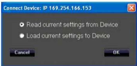
Fig. 4
B. Now click "OK" and read the current settings from the VR112 Cabinet to the User GUI software
Each cabinet will come up as you click "Yes", and click "OK" for as many cabinets as have been networked together.
The first time you do this, just click "Yes" and "OK" for one cabinet, so as to look at just one device initially.
The Device List D∅ should now show one of the units (or the only unit) as "On-line", See Fig.5, where the arrow points.
| IP | INTERFACE | NAME | UNIQUE ID | STATUS | NET. ID |
| 169.254.218.84 | LAN | VR215_A6 | 7779306474AD | Off-line | A5 |
| 169.254.12.25 | LAN | VR215_00 | 5D24A9B0353E | Off-line | 00 |
| 169.254 98.160 | LAN | VR112_02 | D0BAA5051A7B | Off-line | 02 |
| 169.254.124.110 | LAN | VR112_00 | 740391FF354E | Off-line | 00 |
| 169.254.146.165 | LAN | VR112_00 | 3307B2178312 | Off-line | 00 |
| 169.254.150.165 | LAN | VR112_00 | 3303B2178411 | Off-line | 00 |
| 169.254.166.153 | LAN | VR112_00 | 1C91039A2085 | On-line | 00 |
| 169.254.63.32 | LAN | VR112_04 | C02CC6E6A09E | Off-line | 04 |
| 169.254.35.51 | LAN | VR112_00 | 11E6AD9E7153 | Off-line | 00 |
| 169.254.150.135 | LAN | VR112_00 | 3356B1368613 | Off-line | 00 |
| 169.254.23.92 | LAN | VR112_01 | 4A7F075BB1A7 | Off-line | 01 |
| 169.254.230.129 | LAN | VR215_00 | 357DB2338F6A | Off-line | 00 |
Fig.5
C. To display the User GUI parameter pages, double-click on the desired unit in the NAME column in that row, shown by the "X" in Fig. 5
The various parameter pages for the Versarray™ Pro 112 will now come up in a new large window within the Start Window. See Fig. 6
![VR112_01 - IP=169.254.150.147 - program loaded: P01 Load Save Store Recall Settings PW Update Identity Input Clip Limiter BG AG AC BC AL Analog Dante NG Gain Delay Polarity PEG HP Crop Noise B HP/LP PEQ Delay Polarity Gain Crop Limiter Low HP/LP PEQ Delay Polarity Gain Crop Limiter High Temperature [℃] 25 Volume 6dB 4dB 2dB 0dB Up Down Sensitivity +6dBtu +12dBtu +6dBtu +12dBtu Array Count 2 3 4 6+ Select HP Boost Active Indoor Outdoor Select Low Mid Select Level [dBtu] Analog Input 3 DANTE Input -12 Level [dB] Level [dB] Output L 7.8 5.3 Level [dB] Level [dB] MARANI®FIR](/content/2026/05/1010013/images/699c144d8a09302c0771d14b176567e3be92dd1bef4ee1cea7f37cde546c8d62.jpg)
Fig. 6
The default first page is the View page, which will allow you to adjust cabinet overall gain and input Sensitivity and other basic parameters.
CAUTION!
IT IS STRONGLY SUGGESTED THAT BEFORE YOU PROCEED TO ANY OF THE OTHER PARAMETER PAGES, OR CHANGE ANY SETTINGS ON THIS GUI VIEW PAGE, THAT YOU READ AND UNDERSTAND THE DESCRIPTIONS OF EACH PAGE'S FUNCTIONS!
WARNING!
CHANGES TO THE LIMITER SETTINGS, CROSSOVER SETTINGS, OR INDIVIDUAL DRIVER EQ SETTINGS CAN ALL RESULT IN UNRELIABLE OPERATION OR PREMATURE DRIVER FAILURE!
USE OF SETTINGS OTHER THAN THE FACTORY SETTINGS FOR FUNDAMENTAL PARAMETERS WILL VOID THE WARRANTY!!
Quick Start Instructions, CONT'D
The Versarray™ Pro 112 ships with the default programming set for Non Network Use, where all the rear panel push buttons on the back of the speaker system are active and perform their described function basically as labeled.
See the Section on Using the Non Network Push-Buttons On the VR112 Rear Panel for the details on the operation of this feature.
If you have access to, or can configure a network to a PC as described above, then use of the Factory Presets will provide superior performance to the use of the rear panel push-button settings.
In order to load Presets for Network based programming and use, you will need to access the Factory files stored in the Versarray™ Pro series User GUI PC software folders for Presets.
Loading Presets from PC GUI software folders
- Position the View page from Fig. 6 so it does not cover up the row of icons at the top left corner of the Start page, but still has the bottom portions of the View page visible.
In the File Management group A, select "Load", as seen in the upper left-hand corner of Fig. 7 below.
![FREE MANAGEMENT 50.14 program loaded: PSX Load Save Store Recall Settings PW Update Identity Input Clip Limiter BG AS AC BC AL Analog HP/LP PEQ Delay Polarity Gain Crop Limiter Low Dante NG Gain Delay Polarity PEQ HP Crop HP/LP PEQ Delay Polarity Gain Crop Limiter High Signal FLOW CHART Temperature (°C) 25 Volume 6dB 4dB 2dB 0dB Input Source Analog Up Down Dante Sensitivity +6dBu +12dBu Dante - Analog backup +6dBu +12dBu Internal Noise Generator Enable White Noise -50 Array Count 2 3 4 6+ Pink Noise Select HF Boost Low Mid Active Indoor Outdoor Select Select Level [dB] K F G 10 11 12 ML/NT®IFR](/content/2026/05/1010013/images/59d5590e4078b068ef0367ed23484db26dfb9a409e6465e6993ed7b12e6f2893.jpg)
Fig. 7
- A typical Windows file manager window will come up with the File Folder contents for the Preset files, generally located at:
For Windows 7 and for Windows XP - C:\Program Files (x86)\VR Series v1.2.X\Preset
For Windows 10 - C:\Program Files\VR Series v1.2.X\Preset. No (x86)
where C: is the root drive where the VR112 PC GUI software has been located, and "X" is the version of the VR112 PC GUI software you have loaded onto the PC.
We will pick the 6Cabs_Mild_Angle Preset file, as this is a very useful and common set of parameters to use.
Highlight and Click "OPEN" on the 6Cabs_Mild_Angle Preset file.
The bar across the top of the View window should now display the "Program Loaded" as the "6Cabs_Mild_Angle" Preset. During normal operation after being fully informed of the rest of the page parameter functions, you can now proceed to make any recommended adjustments or dial in some mild venue EQ on the VR112 using the other pages as listed out below.
CAUTION!
IT IS STRONGLY SUGGESTED THAT BEFORE YOU PROCEED TO ANY OF THE OTHER PARAMETER PAGES, OR CHANGE ANY SETTINGS ON THIS GUI VIEW PAGE, THAT YOU READ AND UNDERSTAND THE DESCRIPTIONS OF EACH PAGE'S FUNCTIONS!
WARNING!
CHANGES TO THE LIMITER SETTINGS, CROSSOVER SETTINGS, OR INDIVIDUAL DRIVER EQ SETTINGS CAN ALL RESULT IN UNRELIABLE OPERATION OR PREMATURE DRIVER FAILURE!
USE OF SETTINGS OTHER THAN THE FACTORY SETTINGS FOR FUNDAMENTAL PARAMETERS WILL VOID THE WARRANTY!!
The next section deals with the details of the parameter pages: The View, Input, Lows and Highs pages.
Full List of Features of the Versarray™ Pro series PC Software GUI Pages for the Versarray™ Pro 112
View Page
This is the first page that comes up after loading a Preset into the Versarray™ Pro 112, or when connecting with an existing Preset already present in the speaker system. See Fig. 7.
Preset File Management Group A
This includes the icons for Load, Save, Store and Recall.
Load (Preset) instructions have already been covered in the Quick Start Instructions for connecting to the Versarray™ Pro 112 system and for up-loading a Preset to the Versarray™ Pro 112.
Save (Preset) function is the usual Windows file manager format, and files saved to the PC folders can be very long file names, with the usual Windows restrictions on allowed characters. However, it is good to keep in mind that the DSP memory can only display 16 characters, including spaces, so keep the important or descriptive stuff towards the beginning of the file name.
Store (Preset) function refers to storing the currently loaded Preset DSP file into the DSP system memory of the power amp in the cabinet. See Fig. 8

Fig. 8
Sixteen characters are available for the file name, so when saving custom presets to the PC software folder outside the Versarray™ Pro 112, keep that limitation in mind for the file name, and put the
important descriptors first in the file name.
If a Factory Preset has been customized, then type in your desired name and use that to save the file into DSP memory.
Recall (Preset) function loads a DSP file from the on-board memory into the DSP system in the power amp, and makes it the active working Preset settings for the Versarray™ Pro 112 system. See Fig. 9.
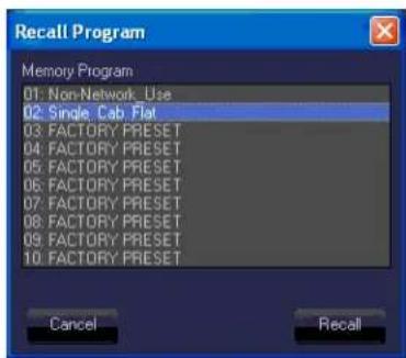
Fig. 9
The Recall function only brings in the Preset level of parameters, if there was a different set of Project settings involved with that file, then the appropriate Project file from the PC software Program folder will also need to be loaded into the Versarray™ Pro 112 DSP system as the next step.
All the Crest Factory Presets use the same basic settings, and thus, can be interchanged by merely changing the Presets or Recalling from memory.
If setting the system up for network use from now on, see the sub-section titled Setting a Cabinet Up for Network Use Only, in section 4 below.
Signal Flow Chart Group B
This chart shows the signal flow through the Versarray™ Pro 112 DSP system.
It provides a indicator in the form of an Input Clip Limiter, which shows input stage electrical clipping. Gain within the DSP system has been set so as to avoid the signal from clipping the input significantly before the internal processes reach compression and limiting. Re-adjustment of the internal gain structure will require monitoring this indicator to assure that you are not clipping the input stage instead of engaging the appropriate levels of internal compression and limiting.
Input Source is displayed, and is controlled at the View page section 2, located just below the Signal Flow Chart Group at the left side of the Window.
Three muting points are accessible directly from this flow chart, as shown by the light blue "X"s on the loudspeaker symbol block, see Fig. 10

flowchart
graph LR
    A["Input Clip Limiter"] --> B["Analog"]
    A --> C["Dante"]
    A --> D["Noise G"]
    B --> E["BG"]
    C --> F["NG Gain Delay Polarity PEQ HP Cmp"]
    D --> G["AC"]
    E --> H["Signal Flow Chart"]
    F --> H
    G --> H
    H --> I["Signal Flow Chart"]
    I --> J["High"]
    I --> K["Low"]
    I --> L["High"]
Fig. 10
When clicked on to mute, the loudspeaker block turns red, and mutes the signal flow at that point.
Clicking on the block again un-mutes the signal chain at that point.
There are also mute controls on the Input Page, and on the Lows and the Highs Page, if the mute is triggered at these locations, the indication still will occur at the View page as well via a red block icon.
For the various level meters provided at the right hand of all the GUI pages, some have a selectable monitor point, the location of this point is shown on the Signal Flow Chart.
BG is Before Gain, AG is After Gain, AC is After Compression, BC is Before Compression, and AL is After Limiting.
Section 1
Temperature
Displays the operating temperature of the power amp output stage in degrees Centigrade.
Allows monitoring the temperature of each amp in an array as one switches from Device to Device
Section 2
Input Source
Radio Buttons allow selection of the input from Analog XLR in, to Dante Ethernet network input, to Dante with Analog back-up. Input level gains are controlled in Sections 10 and 11, see appropriate Section.
Section 3
Internal Noise Generator Enable
Checkbox enabled. Provides the choice between White Noise and Pink Noise via Radio Button selection, and a Level control with a range from -50 dBFS to -20 dBFS. Note that even at -50 dBFS, the level is substantial when one is up close to the speaker, and could startle someone if unaware of the initiation of the event. Strongly recommended that the noise be turned on at the lowest level, and then dis-engaged, and to then adjust level slowly up in moderate increments and re-engage to reach the desired output.
Section 4
Settings
This section contains the settings that are associated with the Project parameters that are not changed with the loading of a different Preset.
Clicking on this Icon will bring a menu of the various settings choices available. See Fig. 11.

Fig. 11
The default menu selection is for assigning the LAN addresses in the line array network.
In order for the data to be entered, or any changes to register with the DSP system, you must click on the Apply button, and then the EXIT button. This procedure must be done for each of the Settings choices, or the change or data entered will be lost.
NAME
Allows up to 16 characters to name a given Versarray™ Pro 112 cabinet. Default name is just VR112
AUTO-SLEEP
Checkbox enabled, this allows a Radio Button choice between 3, 5 or 10 minutes before the SLEEP mode is engaged. Auto-Sleep mutes the power amplifiers after the designated time has elapsed, and then detects the presence of an audio signal and un-mutes the amplifiers within approximately a few ms.
AUTO-STANDBY
Checkbox enabled, this allows a Radio Button choice between 15, 30 or 60 minutes before the STAND-BY mode is engaged. Auto-Standby powers the amplifiers down after the designated time has elapsed, and then detects the presence of an audio signal and un-mutes the amplifiers within approximately a few hundred ms.
INP HEADROOM
Input Headroom (+12 dB), Checkbox enabled, is used to provide a safety margin for DSP set-ups that use a lot of gain above the 0 dB line on the Frequency Response Graphic Display (See Sections 14, 27 or 43). The Factory settings do not need this enabled, gain structure has been optimized for the EQ settings and gain used.
If this feature is enabled, it is recommended that the input Sensitivity (Section D) be changed to +12 dBu from the nominal Factory setting of +6 dBu.
NETWORK ID
Allows you to set the network ID from hexadecimal 00 to FF.
There is a set of rear panel buttons that provide for this to be changed as well.
HF BOOST
Boosts the high frequencies above 2 kHz by a selected amount, levels ranging from 0 dB to +4 dB in 0.1 dB increments. The Factory Setting is +3.2 dB.
There is a rear panel button that provides for this to be engaged or not, and a GUI incorporated Select button in Section F of the View Page.
The HF Boost rear panel button is generally only used when the system is in Non-Network Use mode, and for cabinets that have been angled a lot more than the rest of the line, and that need a corresponding added boost to the HF's. An example of this would be the bottom cabinets of a "J-line" shaped line-array.
The Presets available for use with a Network connected system provide for the needed HF boost amounts and types for a given Preset file purposed use.
See the Section on Using the Non Network Push-Button System for the details on the operation of
this rear panel push button feature.
ARRAY COUNT
Provides 4 Up-Down Control Boxes for differing amounts of HF boost, depending on the number of cabinets deployed in a line array
Boosts the high frequencies above 2 kHz by a selected amount, allowable levels ranging from 0 dB to +8 dB in 0.1 dB increments.
The Factory Settings are:
2 Cabs is +0 dB.
3 Cabs is +2.7 dB.
4 Cabs is +5.4 dB.
6+ Cabs is +6.5 dB.
There are rear panel buttons that provides for the selected array count to be active, and a GUI incorporated set of buttons in Section F of the View Page.
See the Section on Using the Non Network Push-Buttons On the VR112 Rear Panel for the details on the operation of this rear panel push button feature.
LOW MID
Provides a Low Shelf cut for when more than 6 to 8 cabinets are in the Line Array.
The parameters are: - 3.5 dB at 180 Hz, Q of 1.7
The associated rear panel button or the GUI Select button are generally only used when the system is in Non-Network_Use mode, as the Network Presets already incorporate the correct EQ for this aspect and a more exact number of cabinets in the line array.
As a reminder, in order for the Settings data to be entered, or any changes to register with the DSP system, you must click on the Apply button, and then the EXIT button. This procedure must be done for each of the Settings choices, or the change or data entered will be lost.
Setting a Cabinet Up for Network Use Only
The following two Settings parameters should be custom configured for regular use with a network, rather than remain in the factory default settings.
HF BOOST
ARRAY COUNT
Both of these parameters can have their boost amounts set to 0 dB, so that activation of the HF BOOST or the ARRAY COUNT buttons will not ADD additional HF gain on top of what is already dialed in with a given Factory or Custom Preset.
That way, if the HF BOOST button is inadvertently activated, or the ARRAY COUNT is set to something other than 2, the correct amount of HF gain will still be applied.
So for the ARRAY COUNT parameter, set the individual button boost amounts all to zero dB.
2 Cabs is +0 dB.
3 Cabs is +0 dB.
4 Cabs is +0 dB.
6+ Cabs is +0 dB.
The parameters in the Settings menu DO NOT carry over from any Preset files, they do not Save into a Preset, nor do they Load when a Preset is loaded. So each cabinet will have to be adjusted individually. Once this has been done, the Presets will not change these parameters, and there need be no concern about inadvertent button activation, etc.
Section 5
FW Update
This section allows for a firmware update to the DSP operating system, something that will only be done on an infrequent (if ever) basis. Contact Crest Audio/Peavey Electronics for information on whether a firmware update is available or desirable. Instructions for an update will be provided at that time as needed.
Section 6
Identify
Clicking on this icon will light up an LED on the front panel of the Versarray™ Pro 112 speaker system, to allow one to see which cabinet in an array is being accessed.
Section C
Volume
Up and Down buttons provide for changing the Level of the audio signal.
Factory default is 0 dB, with a range down to -6 dB in 2 dB steps.
There are rear panel buttons that provides for the selected Level to be chosen as well.
These Level choices become handy when using amplitude shading of the line array, for progressively reducing the output of a bottom portion of an array, or the J section of a J-line array.
Section D
Sensitivity
Click to choose buttons allow selection of either +6 dBu or +12 dBu sensitivity of the Analog input (XLR in) of the Versarray™ Pro 112 system. The Factory default is +6 dBu, and the gain structure of the rest of the DSP based preamp system has been based on this sensitivity level. If the +6 dBu is too sensitive for your requirements, then you can select the +12 dBu option instead with no penalty in performance or noise.
With the Input Sensitivity set to +6 dBu, it takes 1.75 VAC RMS to drive the Versarray™ Pro 112 system to full power output on music. That would change to 3.5 VAC with a change of the Sensitivity to +12 dBu.
Note that with the Sensitivity set to +12 dBu, it might be more likely that the input stage could be overdriven and clipped. Checking the Input Clip Indicator in Section B would be advisable if it is felt necessary to engage the +12 dBu sensitivity setting.
Section E
Array Count
Provides a single button to cycle through differing amounts of HF boost, depending on the number of cabinets deployed in a line array. Boosts the high frequencies above 2 kHz by a selected amount.
Factory Settings are:
2 Cabs is +0 dB.
3 Cabs is +2.7 dB.
4 Cabs is +5.4 dB.
6+ Cabs is +6.5 dB.
These buttons are only useful when used for the Non-Network_Use Factory Default Preset file is loaded. These happen to be the Factory Default files the unit initially comes loaded with, out of the
box.
Once it has been determined that the system will always be used with, or is being permanently set up with a network connection, it is strongly recommended that the buttons are all set to 0 dB boost, so that additional push button boost beyond what has already been programmed on those Presets, can not be inadvertently added on.
Section F
HF Boost
Provides a high frequency boost for added cabinets or when the cabinet is angled more than a gentle curve, like at the end of a “J-Line”. Boost amount ranges from 0 dB to +4.0 dB in 0.1 dB increments, adjustable in the Settings section 4 menu.
Factory setting is +3.2 dB.
Generally only used when the system is in Non-Network_Use mode, as the Network accessible MLAS™ Presets already incorporate the correct EQ for this aspect, and for a more exact number of cabinets in the line array. It is strongly recommended that the HF Boost button is set to 0 dB boost for regular network use, or network set-up with MLAS™ Presets, so that extra HF boost is not accidentally applied while a multi-cabinet Preset is loaded.
Use caution engaging this button with the Array Count button set to 4 Cabinets or higher, as this engages a large total sum amount of HF EQ boost.
Section G
Low-Mid
Provides a Low Shelf cut for when more than 6 to 8 cabinets are in the Line Array.
The parameters are: - 3.5 dB at 180 Hz, Q of 1.7
Normal indicator position should be Outdoor.
Generally only used when the system is in Non-Network_Use mode, as the Network Presets already incorporate the correct EQ for this aspect, and for a more exact number of cabinets in the line array.
Section H
Device pages
Icon selection of which page is on top and visible:
View page
Input Page
Output page L (lows)
Output page H (highs)
Section J
Power
Button turns the power amplifier Off if it is On, and On if it is Off. Turns Red when the power amp is Off.
Section K
On-line/Off-line Indicator
Indicates whether or not that particular cabinet is connected to the DSP GUI network.
It does not indicate Dante connection or any other network status.
Lights up Red when On-line, Black when Off-line.
Section 7
Level Meter, monitors signal level at the point marked BG (Before Gain) in the Signal Flow Chart
Section B diagram, see Fig.10 for the details.
This is the level of the signal at the input to the DSP Preamp, and shows clipping of the analog input stage (2nd from top indicator bar turns red), as well as compression due to the input stage ADC overdrive prevention circuit (top indicator bar turns yellow).
Section 8
Level Meter for the Lows
Level Meter, monitors signal level at the point marked AL (After Limiter) in the Signal Flow Chart Section B diagram, see Fig.10 for the details.
This is the level of the signal at the output of the DSP Preamp Low channel, and shows clipping of the analog output stage (2nd from top indicator bar turns red), as well as compression as dialed in at Sections 29 and 30 (top indicator bar turns yellow).
Section 9
Level Meter for the Highs
Level Meter, monitors signal level at the point marked AL (After Limiter) in the Signal Flow Chart Section B diagram, see Fig.10 for the details.
This is the level of the signal at the output of the DSP Preamp High channel, and shows clipping of the analog output stage (2nd from top indicator bar turns red), as well as compression as dialed in at Sections 45 and 46 (top indicator bar turns yellow).
Section 10
Analog Input Level
Master Gain control for the analog input. Has a range of +/- 12 dB.
Factory Setting is +3 dB. Realize that turning this gain down will NOT prevent input stage clipping, and that in order to try and avoid input stage clipping, this control should be set at 0 dB or above, so the gain inside the Versarray™ Pro 112 will allow the input signal level to be reduced and avoid the input stage clipping.
Section 11
DANTE Input Level
Local gain control for the DANTE input. Has a range of +/- 12 dB.
Factory Setting is -12 dB, so the level can be adjusted as appropriate after establishing DANTE connection.
Section 12
Output L Level
This sets the output gain of the Lows channel, which drives the woofer.
It is strongly recommend that this level not be changed, as it sets the relationship between the woofer output level and the tweeters output level.
If the gain must be changed for some reason, then maintain the relationship of the gain difference between the woofer and the tweeters. The woofer should be driven 2.5 dB higher than the tweeters.
Factory setting for this section is +7.8 dB
Changing this setting may render the available EASE Focus 3 and EASE modeling data incorrect, and change the horizontal polar behavior of the Versarray™ Pro 112 system.
Section 13
Output H Level
This sets the output gain of the Highs channel, which drives the tweeters.
It is strongly recommend that this level not be changed, as it sets the relationship between the woofer
output level and the tweeters output level.
If the gain must be changed for some reason, then maintain the relationship of the gain difference between the woofer and the tweeters. The woofer should be driven 2.5 dB higher than the tweeters. Factory setting for this section is +5.3 dB
Changing this setting may render the available EASE Focus 3 and EASE modeling data incorrect, and change the horizontal polar behavior of the Versarray™ Pro 112 system.
NOTE: SETTING BOTH SECTIONS 12 AND 13 DOWN WHILE RETAINING THE LEVEL DIFFERENCE OF 2.5 DB MAY NOT ALLOW FULL DRIVE TO THE POWER AMP TO BE REACHED WITHOUT INPUT STAGE CLIPPING OCCURING.
Input Page
The Input Page of the Versarray™ Pro 112 DSP GUI provides an overview of controls and parameters of the system, including EQ and compression of the entire signal. See Fig. 12
![VR117_01 - IP=169.254.150.147 - program loaded: P01 Load Save Store Recall Settings FW Update Identity 20Hz 100Hz 1 kHz 10 kHz 20 kHz +30 -30 +30 -30 +30 -30 +30 -30 +30 -30 +30 -30 +30 -30 +30 -30 +30 -30 +30 -30 +30 -30 +30 -30 +30 -30 +35 -35 +35 -35 +35 -35 +35 -35 +35 -35 +35 -35 +35 -35 +35 -35 +35 -35 +35 -35 +35 -35 +35 -35 +35 -35 +30 -30 +30 -30 +30 -30 +30 -30 +30 -30 +30 -30 +30 -30 +30 -30 +30 -30 +30 -30 +30 -30 +30 -30 +28 -28 -28 -28 -28 -28 -28 -28 -28 -28 -28 -28 -28 -28 -28 -28 -28 -28 -28 -28 -28 -28 -28 -28 -28 -28 14 14 Cunea View All Mag Phase Delay Unit Multi ms max mode Delay [ms] 0 Adj Fine Level [dB] 22 Gain Reduction 24 Core 25 26 RMS Compensator 27 Bypass 28 RMS Compensator 29 Thr [dBfs] Ratio [inOut] Knee [s] Release [inl] Attack [inl] Make-up [dS] Noise Gate 15 FIR 16 FIR 17 EQ Filters 18 High Pass Fates 19 High Pass Fates 20 High Pass Fates 21 High Pass Fates 22 High Pass Fates 23 High Pass Fates 24 High Pass Fates 25 High Pass Fates 26 High Pass Fates 27 High Pass Fates 28 High Pass Fates 29 High Pass Fates 30 High Pass Fates 31 High Pass Fates 32 High Pass Fates 33 High Pass Fates 34 High Pass Fates 35 High Pass Fates 36 High Pass Fates 37 High Pass Fates 38 High Pass Fates 39 High Pass Fates 40 High Pass Fates 41 High Pass Fates 42 High Pass Fates 43 High Pass Fates 44 High Pass Fates 45 High Pass Fates 46 High Pass Fates 47 High Pass Fates 48 High Pass Fates 49 High Pass Fates 50 High Pass Fates 51 High Pass Fates 52 High Pass Fates 53 High Pass Fates 54 High Pass Fates 55 High Pass Fates 56 High Pass Fates 57 High Pass Fates 58 High Pass Fates 59 High Pass Fates 60 High Pass Fates 61 High Pass Fates 62 High Pass Fates 63 High Pass Fates 64 High Pass Fates 65 High Pass Fates 66 High Pass Fates 67 High Pass Fates 68 High Pass Fates 69 High Pass Fates 70 High Pass Fates 71 High Pass Fates 72 High Pass Fates 73 High Pass Fates 74 High Pass Fates 75 High Pass Fates 76 High Pass Fates 77 High Pass Fates 78 High Pass Fates 79 High Pass Fates 80 High Pass Fates 81 High Pass Fates 82 High Pass Fates 83 High Pass Fates 84 High Pass Fates 85 High Pass Fates 86 High Pass Fates 87 High Pass Fates 88 High Pass Fates 89 High Pass Fates 90 High Pass Fates 91 High Pass Fates 92 High Pass Fates 93 High Pass Fates 94 High Pass Fates 95 High Pass Fates 96 High Pass Fates 97 High Pass Fates 98 High Pass Fates 99 High Pass Fates 100 Hainup End Up End Up End Up End Up End Up End Up End Up End Up End Up End Up End Up End Up End Up End Up End Up End Up End Up End Up End Up End Up End Up End Up End Up End Up End Up End Up End Up End Up End Up End Up End Up End Up End Up End Up End Up End Up End Up End Up End Up End Up End Up End Up End Up End Up End Up End Up End Up End Up End Up End Up End Ump Ump Ump Ump Ump Ump Ump Ump Ump Ump Ump Ump Ump Ump Ump Ump Ump Ump Ump Ump Ump Ump Ump Ump Ump Ump Ump Ump Ump Ump Ump Ump Ump Ump Ump Ump Ump Ump Ump Ump Ump Ump Ump Ump Ump Ump Ump Ump Ump Ump UMP Ump Ump Ump Ump Ump Ump Ump Ump Ump Ump Ump Ump Ump Ump Ump Ump Ump Ump Ump Ump Ump Ump Ump Ump Ump Ump Ump Ump Ump Ump Ump Ump Ump Ump Ump Ump Ump Ump Ump Ump Ump Ump Ump Ump Ump Ump Ump Ump Ump Uump Ump Ump Ump Ump Ump Ump Ump Ump Ump Ump Ump Ump Ump Ump Ump Ump Ump Ump Ump Ump Ump Ump Ump Ump Ump Ump Ump Ump Ump Ump Ump Ump Ump Ump Ump Ump Ump Ump Ump Ump Ump Ump AURANT®EIFR](/content/2026/05/1010013/images/45469b9e230b8b7f615c20eb4e7e084fff5ad6c26a37ceb9e2fb069ec6ad8a77.jpg)
Fig. 12
Section 14
Frequency and Phase Response Graph and related controls
This section provides a graphical display of the frequency response changes dialed in to this Page. Using the Mag and Phase Radio Buttons, you can toggle between the Magnitude (frequency response) and the Phase of the changes.
The Cursor button places small cursor symbols at all the dialed-in EQ spots on the curve, providing a visual locator and flag for their actions.
The View All button starts a new Window that overlays the three pages curves, the Input Page, the Lows Page and the Highs Page, on one graph. They are not summed, just overlaid on one another.
See Fig. 13
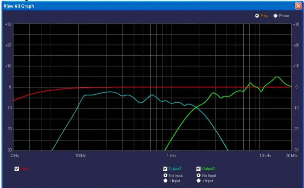
line
| Frequency | Input | Output1 | Output2 | | --------- | ----- | ------- | ------- | | 20Hz | -5 | -30 | - | | 100Hz | -2 | -5 | - | | 1 kHz | -8 | -10 | - | | 10 kHz | -30 | - | +5 | | 20 kHz | 0 | 0 | 0 |Fig. 13
Checkboxes and Radio Buttons provide for various display options from the default view, including the Phase response of all three sections.
Note that these responses are for the electronics only, and DO NOT represent the actual electro-acoustic output of the system, or of the individual drivers.
Section 15
Noise Gate
A noise gate is provided as a means to mute low level noises or sounds from the system.
A Bypass checkbox toggles the noise gate active or inactive. Default setting is Bypassed, as the Versarray™ Pro 112 system is very quiet and free from hiss or hum in and of itself.
parameters
Thr (Threshold) dBFS
The threshold of opening the noise gate ranges from -90 dBFS to -60 dBFS
Release
The release time ranges from 1 to 1000 ms
Attack
The attack time ranges from 30 to 1000 ms
NOTE: If the Noise gate threshold is set too high, or the Attack and Release times are set oddly, the music could be affected, with low level notes cutting on and off as the music plays.
Section 16
FIR
A Bypass checkbox toggles the FIR processing active or inactive.
FIR processing provides a means to correct phase and amplitude deviations beyond what a typical parametric EQ can achieve. This is a specialized Factory set of parameters and data, and is not user adjustable. Factory setting is Bypass.
NOTE: It is strongly recommended that the User not try to change the FIR coefficients, as they could be loaded in with an error in amplitude or bandwidth, and cause excessive drive level to the system or a particular component, causing damage and/or failure of the system or component.
CHANGING THESE SETTINGS FROM THE FACTORY SETTINGS WILL VOID THE WARRANTY!
Section 17
Loudness Filter
An Enable checkbox toggles the loudness function processing active or inactive.
This function provides a bass and treble boost for situations where the sound level is much lower than normal, and will stay that way for a long period of time.
Should not be used for high SPL Sound Reinforcement use.
Factory setting is unchecked.
Section 18
High Pass Filter
This section provides a means to infra-sonic filter the music before it gets to the rest of the signal processing sections, for added protection from non-musical deep bass noises, transients (Pops), and stage borne noises.
Slope/Type is a drop down menu bar, with the following options for filters:
Bypass
6 dB/Oct. Butterworth (BW)
12 dB/Oct. Butterworth
18 dB/Oct. Butterworth
24 dB/Oct. Butterworth
36 dB/Oct. Butterworth
48 dB/Oct. Butterworth
12 dB/Oct. Linkwitz-Riley (LZ)
24 dB/Oct. Linkwitz-Riley
36 dB/Oct. Linkwitz-Riley
48 dB/Oct. Linkwitz-Riley
12 dB/Oct. Bessel (BS)
24 dB/Oct. Bessel
Below the Slope/Type Drop down menu bar, is a Frequency (Hz) box, where you can enter the frequency in directly in Hz. This can range from 20 Hz to 20,000 Hz. Click on the box numerals, and type in the desired frequency in Hz, and hit Enter.
Factory setting is 20 Hz, 12 dB/Oct. Bessel
Altering this setting will undo the optimization of the Versarray™ Pro 112 crossover to the Versarray™ Pro Subs crossover. The frequency and amount of roll-off is carefully considered for minimal sonic impact, and maximum additional protection from LF garbage signals.
Section 19
EQ Filters Section
Ten Bands of parametric EQ are available for the overall system EQ, and provide a lot of performance enhancement of the system.
Each band has the following capabilities:
Amplitude changes up to + and - 6 dB, in 0.5 dB increments.
Filter Types for each band include:
Bell (parametric), with Q ranging from 0.4 to 20
Hi Shelf, with Q ranging from 0.1 to 3.5
Lo Shelf, with Q ranging from 0.1 to 3.5
Low Pass, with Q ranging from 0.1 to 3.5
High Pass, with Q ranging from 0.1 to 3.5
Notch Filter, with Q ranging from 4 to 72
All-Pass1, a 1^st order all-pass filter, no Q adjust (it's 1^st order)
All-Pass2, a 2^nd order all-pass filter, with Q ranging from 4 to 72
Each band has a Bypass button ( Byp ) at the bottom of the EQ strip, which turns off the EQ band changes to make that band "flat", then with another click, that EQ band action is turned back on.
There is a Bypass checkbox for overall bypass of the entire EQ section at once, which toggles the EQ on and off. This is located at the top right-hand side of this section.
There is an EQ Flat button for returning all the bands and settings to 0 dB, but this button does NOT toggle, if clicked, the EQ settings are lost, and you start over again.
If you should accidentally click this button, just re-load the most relevant Preset back into the Versarray™ Pro 112 system from the file folder, or from the on-board DSP memory.
Note: It is strongly recommend that the EQ bands in use for the Factory Presets be left unaltered and NOT be changed by the end user. This is the additional EQ used to generate the Factory Presets for the Versarray™ Pro 112 system, and as such, altering it will defeat to whatever extent the bands are changed, the desired end result of the Preset's use.
This should still leave anywhere from 9 bands of EQ to 6 bands for the non-Bass Boosted Presets, and a minimum of 3 for the worst case Bass Boost Preset.
Any unused EQ bands should have the Byp (Bypass) button clicked on (turns Orange).
CHANGING THE BANDS WITH FACTORY SETTINGS MAY VOID THE WARRANTY!
Section 20
Mute button, a click turns the Input Page signal output OFF.
The icon turns red, and an "X" appears next to the loudspeaker symbol.
To un-mute the signal, click it again.
This action also shows up on the View Page under the Signal Flow Chart B group, where the same icon in the signal chain shows as red when muted. As noted in that section, clicking on the icon while on the View Page will also toggle the Mute On or Off.
Section 21
Delay, sets the delay time of the Input Page signal for the system.
Delay Units, Radio Buttons select the units, either ms (milliseconds) or meters.
Parameter
Adj delay increments are 1 ms (or 0.34 meters), Fine delay increments are approx. 0.0207 ms (or 0.007 meters), with a maximum total delay of 251 ms (or 85.3 meters).
Factory setting for this section is 0 ms.
NOTE: When using the Crest Audio® Versarray™ Mk3 6 Foot Fly Bar to fly a Halo of Multiple VR 112's, and a separate Halo of multiple VR 215 Subs at the recommended hang locations on the flybar, the typical delay needed for the VR112 hang as a whole is approximately 4 ms to align it with the Subs for the best mesh at the crossover.
Section 22
Gain, sets output level of the Input Page.
Range is +/- 12 dB in 0.1 dB increments. Factory setting is +3 dB.
This is the same control as Section 9 or 10 on the View Page, depending on which input has been selected at Section 2. See that section for some notes on it's operation.
Section 23
Level Meter, monitors signal level at the point selected by the Meter Select drop down menu.
The Meter Select drop down menu allows a choice of BG (Before Gain), AG (After Gain), or AC (After Compression). See the Signal Flow Chart Section B diagram Fig.10 for the details of where these monitor points are in the signal chain.
The signal monitor point selection BG duplicates the meter function on the View Page at Section 7.
It is recommended to leave the meter set to either the monitor point of BG or AG, since the next meter shows how much compression is occurring.
The meter shows clipping of the signal (2nd from top indicator bar turns red), as well as compression as dialed in at Section 26 (top indicator bar turns yellow).
Section 24
Cmp Gain Reduction meter, displays the level of compression occurring in Section 26 (top indicator bar turns yellow)..
Section 25
Polarity, provides a checkbox to reverse the polarity of the signal.
The overall polarity would seldom be reversed, except for some special circumstance, normal usage would have the polarity remain normal. Factory setting is normal (unchecked).
Section 26
RMS Compressor Section
This section provides for adjusting the compression parameters of the overall system, and for the Versarray™ Pro 112 it is used to extend the apparent dynamic range of the system, by compressing the signal when it reaches 3 dB below hard limiting (amplifier clipping). The slope (ratio) of the compression is 2:1, so the input signal can increase 6 dB before hitting the Hard Limit point Parameters
Thr (Threshold), sets the threshold of the limiter action, with a range from 0 dBFS to -30 dBFS. Factory Setting is -6 dBFS.
Ratio, sets the slope of the compression curve, ranges from 2:1 to 32:1. Factory Setting is 2:1.
Knee, sets how sharp the compression curve engages relative to the Threshold point, ranges from 0% to 100%. Factory Setting is 100%.
Release, sets the release time after compression has engaged, till the compression is no longer engaged. Ranges from 100 milliseconds to 15000 ms. Factory Setting is 100 ms.
Attack, sets how quickly the compression engages once the threshold point has been passed. Ranges from 0.10 milliseconds to 2000 ms. Factory Setting is 0.1 ms.
Make-Up (Make up gain), has a +/- 12 dB range, in 0.1 dB increments. Factory Setting is 0 dB. There is a Bypass checkbox for overall bypass of the entire Compression section at once, which toggles the Compression on and off. This is located at the top right-hand side of this section.
Lows Output Page
The Lows Output Page of the Versarray™ Pro 112 DSP GUI provides the control of the woofer parameters of the system. See Fig. 14

Fig. 14
Section 27
Frequency and Phase Response Graph and related controls
This section provides a graphical display of the frequency response changes dialed in to this Page. Using the Mag and Phase Radio Buttons, you can toggle between the Magnitude (frequency response) and the Phase of the changes.
The Cursor button places small cursor symbols at all the dialed-in EQ spots on the curve, providing a visual locator and flag for their actions.
The View All button starts a new Window that overlays the three pages curves, the Input Page, the Lows Page and the Highs Page, on one graph. They are not summed, just overlaid on one another. See Fig. 13 from Input Page Section
Checkboxes and Radio Buttons provide for various display options from the default view, including the Phase response of all three sections.
Note that these responses are for the electronics only, and DO NOT represent the actual electro-acoustic output of the system, or of the individual drivers.
Section 28
EQ Filters
Eight Bands of parametric EQ are available for the woofer EQ, and provide a lot of performance enhancement of the system.
Each band has the following capabilities:
Amplitude changes up to + and - 15 dB, in 0.5 dB increments.
Filter Types for each band include:
Bell (parametric), with Q ranging from 0.4 to 128
Hi Shelf, with Q ranging from 0.1 to 5.1
Lo Shelf, with Q ranging from 0.1 to 5.1
Low Pass, with Q ranging from 0.1 to 5.1
High Pass, with Q ranging from 0.1 to 5.1
Notch Filter, with Q ranging from 4 to 104
All-Pass1, a 1^st order all-pass filter, no Q adjust (it's 1^st order)
All-Pass2, a 2^nd order all-pass filter, with Q ranging from 4 to 104
Each band has a Bypass button ( Byp ) at the bottom of the EQ strip, which turns off the EQ band changes to make that band “flat”, then with another click, that EQ band action is turned back on.
There is a Bypass checkbox for overall bypass of the entire EQ section at once, which toggles the EQ on and off. This is located at the top right-hand side of this section.
There is an EQ Flat button for returning all the bands and settings to 0 dB, but this button does NOT toggle, if clicked, the EQ settings are lost, and you start over again.
If you should accidentally click this button, just re-load the most relevant Preset back into the VR112 system from the file folder, or from the on-board DSP memory.
Note it is strongly recommend that this section NOT be changed or altered by the end user. This is the primary EQ for the woofer portion of the Versarray™ Pro 112 system, and as such, altering it even a little will not only degrade the crossover function and the acoustic mesh with the tweeter, but render the available EASE Focus 3 and EASE modeling data incorrect.
CHANGING THESE SETTINGS FROM THE FACTORY SETTINGS WILL VOID THE WARRANTY!
Section 29
RMS Compressor
This section provides for adjusting the compression parameters of the woofer, and is used to control the medium and long-term power to the woofer, so it will not be damaged due to thermal overdrive over the long-term. Thus, the settings may seem odd, but they are there to protect the woofer, as the woofer power amp has enough continuous power output capability to exceed the long-term thermal capacity of the woofer.
Parameters
Thr (Threshold), sets the threshold of the limiter action, with a range from 0 dBFS to -30 dBFS.
Factory Setting is - 8 dBFS.
Ratio, sets the slope of the compression curve, ranges from 2:1 to 32:1.
Factory Setting is 32:1
Knee, sets how sharp the compression curve engages relative to the Threshold point, ranges from 0% to 100%. Factory Setting is 100%.
Release, sets the release time after compression has engaged, till the compression is no longer engaged. Ranges from 100 milliseconds to 15000 ms. Factory Setting is 200ms.
Attack, sets how quickly the compression engages once the threshold point has been passed.
Ranges from 0.10 milliseconds to 2000 ms. Factory Setting is 160 ms.
Make-Up (Make up gain), has a +/- 12 dB range, in 0.1 dB increments. Factory Setting is 0 dB.
There is a Bypass checkbox for overall bypass of the entire Compression section at once, which toggles the Compression on and off. This is located at the top right-hand side of this section.
CHANGING THESE SETTINGS FROM THE FACTORY SETTINGS WILL VOID THE WARRANTY!
Section 30
Peak Limiter
This section provides for adjusting the peak limiting parameters of the woofer, and is used to control the short-term power to the woofer, so it will not be overdriven at high levels. It has an abrupt engagement threshold, no knee, controlled only by the attack and release parameters.
Parameters
Thr (Threshold), sets the threshold of the limiter action, with a range from 0 dBFS to -30 dBFS. Factory Setting is -4 dBFS.
Release, sets the release time after limiting has engaged, till the limiting is no longer engaged.
Ranges from 100 milliseconds to 5,000 ms. Factory Setting is 100 ms.
Attack, sets how quickly the limiting engages once the threshold point has been passed.
Ranges from 1 millisecond to 1,000 ms. Factory Setting is 20 ms.
There is a Bypass checkbox for overall bypass of the entire Peak Limiting section at once, which toggles the peak limiting on and off. This is located at the top right-hand side of this section.
CHANGING THESE SETTINGS FROM THE FACTORY SETTINGS WILL VOID THE WARRANTY!
Section 31
Hard Lim
This is a peak limiter that absolute limits the signal to the level selected, with zero time constants. No attack, no release times.
It's sole purpose it to prevent and avoid PWM amplifier clipping. It has been found that PWM amplifier clipping is much more distressing and audible than a clean clip or limit in the digital domain as implemented in this section.
The proper use of this hard limiter can allow the system to play louder with less apparent distortion than if the PWM amplifier were allowed to clip uncontrolled, effectively extending the apparent loudness of this portion of the system by approximately 3 dB or more.
The previous compression and peak limiting stages take care of the music dynamics with minimal effect on the sound, and this stage minimizes the audible negative impact when the system is driven beyond full peak output power.
Parameter
Threshold, range of 0 dBFS to -9 dBFS. Factory Setting is -2.5
Indicator
Has a Limit indicator icon to show when Hard Limiting is occurring, located at the top of this sections strip.
CHANGING THIS SETTING FROM THE FACTORY SETTING WILL VOID THE WARRANTY!
Section 32
L/H Link, links the Makeup Gain after the Hard Limiter of the Lows Page section and the Highs Page sections together to the same value. A checkbox toggles it on and off. Not recommended for normal or Factory Preset use.
Section 33
Makeup (Make up gain),
Range is 0 dB to +9 dB.
It is recommended that this control be left at 0 dB, as adding gain at this point will defeat the correct action of the Hard Limiter as Factory set.
If the Compressors and Limiters are re-configured away from Factory settings (which will void the Warranty), then this control may be of some utility.
Section 34
Delay, sets the delay time of the Lows Page signal for the woofer.
Delay Units, Radio Buttons select the units, either ms (milliseconds) or meters.
Parameter
Adj delay increments are 1 ms (or 0.34 meters), Fine delay increments are approx. 0.0207 ms (or 0.007 meters), with a maximum total delay of 41 ms (or 13.6 meters).
Factory setting for this section is 0.103 ms.
Changing this setting will render the available EASE Focus 3 and EASE modeling data incorrect, and change the horizontal polar behavior of the Versarray™ Pro 112 system.
Section 35
Mute button, a click turns the Lows Page signal output OFF.
The icon turns red, and an "X" appears next to the loudspeaker symbol.
To un-mute the signal, click it again.
This action also shows up on the View Page under the Signal Flow Chart B group, where the same icon in the signal chain shows as red when muted. As noted in that section, clicking on the icon while on the View Page will also toggle the Mute On or Off.
Section 36
Gain, sets output level of the Lows Page (woofer output).
Range is +/- 12 dB in 0.1 dB increments.
The Factory Presets use this point to add gain for the overall gain structure to minimize input stage and internal DSP system clipping or overload, as well as to balance the woofer and tweeter output levels to each other.
Factory Default is +7.8 dB.
Changing this setting will render the available EASE Focus 3 and EASE modeling data incorrect, and change the horizontal polar behavior of the Versarray™ Pro 112 system, and may void the Warranty.
Section 37
Level Meter, monitors signal level at the point selected by the Meter Select drop down menu.
The Meter Select drop down menu allows a choice of BC (Before Compression), or AL (After
Limiting). See the Signal Flow Chart Section B diagram Fig.10 for the details of where these points are in the signal chain.
It is recommended to leave the meter set to the default monitor point of BC, since the next two meters show how much compression and limiting is occurring.
The meter shows clipping of the signal (2nd from top indicator bar turns red), as well as compression as dialed in at Sections 29 and 30 (top indicator bar turns yellow).
Section 38
Cmp Gain Reduction meter, displays the level of compression occurring in section 29.
Section 39
Lim Gain Reduction meter, displays the level of limiting occurring in section 30.
This meter will tend to display up to approximately 3 to 4 dB of Gain Reduction at maximum reasonable output of the system. Driving the system harder than this will tend to result in increasingly audible distortion and/or compression, and is not recommended for high quality music playback or Sound Reinforcement.
Section 40
Polarity, provides a checkbox to reverse the polarity of the signal.
The woofer polarity would seldom be reversed, except for some special circumstance, normal usage would have the polarity remain normal. Factory setting is normal (unchecked).
Section 41
High Pass Filter, provides the control of the crossover parameters for the Low Frequency roll-off of the woofer.
Slope/Type is a drop down menu bar, with the following options for filters:
Bypass
6 dB/Oct. Butterworth (BW)
12 dB/Oct. Butterworth
18 dB/Oct. Butterworth
24 dB/Oct. Butterworth
36 dB/Oct. Butterworth
48 dB/Oct. Butterworth
12 dB/Oct. Linkwitz-Riley (LZ)
24 dB/Oct. Linkwitz-Riley
36 dB/Oct. Linkwitz-Riley
48 dB/Oct. Linkwitz-Riley
12 dB/Oct. Bessel (BS)
24 dB/Oct. Bessel
Below the Slope/Type Drop down menu bar, is a Frequency (Hz) box, where you can enter the frequency in directly in Hz. This can range from 20 Hz to 20,000 Hz. Click on the box numerals, and type in the desired frequency in Hz, and hit Enter.
Factory setting is 120 Hz, 24 dB/Oct. Bessel
Altering this sections Filter type or Frequency from Factory settings will render the available EASE Focus 3 and EASE modeling data incorrect, and change the horizontal polar behavior of the Versarray™ Pro 112 system, and WILL void the Warranty.
Section 42
Low Pass Filter, provides the control of the crossover parameters for the High Frequency roll-off of the woofer.
Slope/Type is a drop down menu bar, with the following options for filters:
Bypass
6 dB/Oct. Butterworth (BW)
12 dB/Oct. Butterworth
18 dB/Oct. Butterworth
24 dB/Oct. Butterworth
36 dB/Oct. Butterworth
48 dB/Oct. Butterworth
12 dB/Oct. Linkwitz-Riley (LZ)
24 dB/Oct. Linkwitz-Riley
36 dB/Oct. Linkwitz-Riley
48 dB/Oct. Linkwitz-Riley
12 dB/Oct. Bessel (BS)
24 dB/Oct. Bessel
Below the Slope/Type Drop down menu bar, is a Frequency (Hz) box, where you can enter the frequency in directly in Hz. This can range from 20 Hz to 20,000 Hz. Click on the box numerals, and type in the desired frequency in Hz, and hit Enter.
Factory setting is 1845 Hz, 24 dB/Oct. Bessel
Altering this sections Filter type or Frequency from Factory settings will render the available EASE Focus 3 and EASE modeling data incorrect, and change the horizontal polar behavior of the Versarray™ Pro 112 system, and WILL void the Warranty.
Highs Output Page
The Highs Output Page of the Versarray™ Pro 112 DSP GUI provides the control of the ribbon tweeter parameters of the system. See Fig. 15
![VR112_01 IP=169.254.150.147 program loaded: P01 Load Save Store Recall Settings Fw Update Identity 20Hz 100Hz 1 kHz 10 kHz 20 kHz EQ Filters: EQ Fill Bypass EQ Filters Ratio In-Out Knee T3 Release Ins1 Attack Ins1 Peak Under Peak Under Hard Line Line High Pass Filter Slope/Type 24dB/oot BS Frequency [Hz] 1966 Low Pass Filter Slope/Type Bypass Frequency [Hz] MARANT®IFIR](/content/2026/05/1010013/images/95b637e67bcfdfbaf133a3478abd4720c18d9d9c2670d3b79d7c1977b51dcbeb.jpg)
Fig. 15
Section 43
Frequency and Phase Response Graph and related controls
This section provides a graphical display of the frequency response changes dialed in to this Page. Using the Mag and Phase Radio Buttons, you can toggle between the Magnitude (frequency response) and the Phase of the changes.
The Cursor button places small cursor symbols at all the dialed-in EQ spots on the curve, providing a visual locator and flag for their actions.
The View All button starts a new Window that overlays the three pages curves, the Input Page, the Lows Page and the Highs Page, on one graph. They are not summed, just overlaid on one another. See Fig. 13 and the accompanying text from the previous segment.
Section 44
EQ Filters
Eight Bands of parametric EQ are available for the tweeter EQ, and provide a lot of performance enhancement of the system.
Each band has the following capabilities:
Amplitude changes up to + and - 15 dB, in 0.5 dB increments.
Filter Types for each band include:
Bell (parametric), with Q ranging from 0.4 to 128
Hi Shelf, with Q ranging from 0.1 to 5.1
Lo Shelf, with Q ranging from 0.1 to 5.1
Low Pass, with Q ranging from 0.1 to 5.1
High Pass, with Q ranging from 0.1 to 5.1
Notch Filter, with Q ranging from 4 to 104
All-Pass1, a 1^st order all-pass filter, no Q adjust (it's 1^st order)
All-Pass2, a 2^nd order all-pass filter, with Q ranging from 4 to 104
Each band has a Bypass button ( Byp ) at the bottom of the EQ strip, which turns off the EQ band changes to make that band “flat”, then with another click, that EQ band action is turned back on.
There is a Bypass checkbox for overall bypass of the entire EQ section at once, which toggles the EQ on and off. This is located at the top right-hand side of this section.
There is an EQ Flat button for returning all the bands and settings to 0 dB, but this button does NOT toggle, if clicked, the EQ settings are lost, and you start over again.
If you should accidentally click this button, just re-load the most relevant Preset back into the VR112 system from the file folder, or from the on-board DSP memory.
Note it is strongly recommend that this section NOT be changed or altered by the end user. This is the primary EQ for the tweeter portion of the Versarray™ Pro 112 system, and as such, altering it even a little will not only degrade the crossover function and the acoustic mesh with the woofer, but render the available EASE Focus 3 and EASE modeling data incorrect.
CHANGING THESE SETTINGS FROM THE FACTORY SETTINGS WILL VOID THE WARRANTY!
Section 45
RMS Compressor
This section provides for adjusting the compression parameters of the tweeter, and is used to control the medium and long-term power to the tweeter, so it will not be damaged due to thermal overdrive over the long-term. Thus, the settings may seem odd, but they are there to protect the tweeter, as the tweeter power amp has enough continuous power output capability to exceed the long-term thermal capacity of the tweeter.
Parameters
Thr (Threshold), sets the threshold of the limiter action, with a range from 0 dBFS to -30 dBFS. Factory Setting is -12 dBFS.
Ratio, sets the slope of the compression curve, ranges from 2:1 to 32:1.
Factory Setting is 32:1.
Knee, sets how sharp the compression curve engages relative to the Threshold point, ranges from 0% to 100%. Factory Setting is 100%.
Release, sets the release time after compression has engaged, till the compression is no longer engaged. Ranges from 100 milliseconds to 15000 ms. Factory Setting is 250 ms.
Attack, sets how quickly the compression engages once the threshold point has been passed. Ranges from 0.10 milliseconds to 2000 ms. Factory Setting is 160 ms.
Make-Up (Make up gain), has a +/- 12 dB range, in 0.1 dB increments. Factory Setting is 0 dB. There is a Bypass checkbox for overall bypass of the entire Compression section at once, which toggles the Compression on and off. This is located at the top right-hand side of this section.
CHANGING THESE SETTINGS FROM THE FACTORY SETTINGS WILL VOID THE WARRANTY!
Section 46
Peak Limiter
This section provides for adjusting the peak limiting parameters of the tweeter, and is used to control the short-term power to the tweeter, so it will not be overdriven at high levels. It has an abrupt engagement threshold, no knee, controlled only by the attack and release parameters.
Parameters
Thr (Threshold), sets the threshold of the limiter action, with a range from 0 dBFS to -30 dBFS. Factory Setting is -6 dBFS.
Release, sets the release time after limiting has engaged, till the limiting is no longer engaged.
Ranges from 100 milliseconds to 5,000 ms. Factory Setting is 100 ms
Attack, sets how quickly the limiting engages once the threshold point has been passed.
Ranges from 1 millisecond to 1,000 ms. Factory Setting is 10 ms.
There is a Bypass checkbox for overall bypass of the entire Peak Limiter section at once, which toggles the peak limiting on and off. This is located at the top right-hand side of this section.
CHANGING THESE SETTINGS FROM THE FACTORY SETTINGS WILL VOID THE WARRANTY!
Section 47
Hard Lim
This is a peak limiter that absolute limits the signal to the level selected, with zero time constants. No attack, no release times.
It's sole purpose is to prevent and avoid PWM amplifier clipping. It has been found that PWM amplifier clipping is much more distressing and audible than a clean clip or limit in the digital domain as implemented in this section.
The proper use of this hard limiter can allow the system to play louder with less apparent distortion than if the PWM amplifier were allowed to clip uncontrolled, effectively extending the apparent loudness of this portion of the system by approximately 3 dB or more.
The previous compression and peak limiting stages take care of the music dynamics with minimal effect on the sound, and this stage minimizes the audible negative impact when the system is driven beyond full peak output power.
Parameter
Threshold, range of 0 dBFS to -9 dBFS. Factory Setting is -4 dB.
Indicator
Has a Limit indicator icon to show when Hard Limiting is occurring, located at the top of this sections strip.
CHANGING THIS SETTING FROM THE FACTORY SETTING WILL VOID THE WARRANTY!
Section 48
L/H Link, links the Makeup Gain after the Hard Limiter of the Lows Page section and the Highs Page sections together to the same value. A checkbox toggles it on and off. Not recommended for normal or Factory Preset use.
Section 49
Makeup (Make up gain),
Range is 0 dB to +9 dB. Factory Setting is 0 dB.
It is recommended that this control be left at 0 dB, as adding gain at this point will defeat the correct action of the Hard Limiter as Factory set.
If the Compressors and Limiters are re-configured away from Factory settings (which will void the Warranty), then this control may be of some utility.
Section 50
Delay, sets the delay time of the Highs Page signal for the tweeter.
Delay Units, Radio Buttons select the units, either ms (milliseconds) or meters.
Parameter
Adj delay increments are 1 ms (or 0.34 meters), Fine delay increments are approx. 0.0207 ms (or 0.007 meters), with a maximum total delay of 41 ms (or 13.6 meters).
Factory setting for this section is 0 ms.
Changing this setting will render the available EASE Focus 3 and EASE modeling data incorrect, and change the horizontal polar behavior of the Versarray™ Pro 112 system.
Section 51
Mute button, a click turns the Highs Page signal output OFF.
The icon turns red, and an "X" appears next to the loudspeaker symbol.
To un-mute the signal, click it again.
This action also shows up on the View Page under the Signal Flow Chart B group, where the same icon in the signal chain shows as red when muted. As noted in that section, clicking on the icon while on the View Page will also toggle the Mute On or Off.
Section 52
Gain, sets output level of the Highs Page (tweeter output).
Range is +/- 12 dB in 0.1 dB increments. Factory Setting is +5.3 dB.
The Factory Presets use this point to add gain for the overall gain structure to minimize input stage and internal DSP system clipping or overload, as well as to balance the woofer and tweeter output levels to each other.
Changing this setting will render the available EASE Focus 3 and EASE modeling data incorrect, and change the horizontal polar behavior of the Versarray™ Pro 112 system, and may void the Warranty.
Section 53
Level Meter, monitors signal level at the point selected by the Meter Select drop down menu.
The Meter Select drop down menu allows a choice of BC (Before Compression), or AL (After Limiting). See the Signal Flow Chart Section B diagram Fig.10 for the details of where these points are in the signal chain.
It is recommended to leave the meter set to the default monitor point of BC, since the next two meters show how much compression and limiting is occurring.
The meter shows clipping of the signal (2nd from top indicator bar turns red), as well as compression as dialed in at Sections 29 and 30 (top indicator bar turns yellow).
Section 54
Cmp Gain Reduction meter, displays the level of compression occurring in section 45.
Section 55
Lim Gain Reduction meter, displays the level of limiting occurring in section 46.
This meter will tend to display up to approximately 4 to 6 dB of Gain Reduction at maximum reasonable output of the system. Driving the system harder than this will tend to result in increasingly audible distortion and/or compression, and is not recommended for high quality music playback or Sound Reinforcement.
Section 56
Polarity, provides a checkbox to reverse the polarity of the signal.
The tweeter polarity has been reversed by design, and would seldom be changed, except for some special circumstance, normal usage would have the polarity remain reversed. Factory setting is reversed (checked). If the polarity of the woofer is ever reversed for any reason, then the tweeter polarity should be changed to normal, or it will render the available EASE Focus 3 and EASE modeling data incorrect, and change the horizontal polar behavior of the Versarray™ Pro 112 system.
Section 57
High Pass Filter, provides the control of the crossover parameters for the Low Frequency roll-off of the tweeter.
Slope/Type is a drop down menu bar, with the following options for filters:
Bypass
6 dB/Oct. Butterworth (BW)
12 dB/Oct. Butterworth
18 dB/Oct. Butterworth
24 dB/Oct. Butterworth
36 dB/Oct. Butterworth
48 dB/Oct. Butterworth
12 dB/Oct. Linkwitz-Riley (LZ)
24 dB/Oct. Linkwitz-Riley
36 dB/Oct. Linkwitz-Riley
48 dB/Oct. Linkwitz-Riley
12 dB/Oct. Bessel (BS)
24 dB/Oct. Bessel
Below the Slope/Type Drop down menu bar, is a Frequency (Hz) box, where you can enter the frequency in directly in Hz. This can range from 20 Hz to 20,000 Hz. Click on the box numerals, and type in the desired frequency in Hz, and hit Enter.
Factory setting is 1955 Hz, 24 dB/Oct. Bessel
Altering this sections Filter type or Frequency from Factory settings will render the available EASE Focus 3 and EASE modeling data incorrect, and change the horizontal polar behavior of the Versarray™ Pro 112 system, and WILL void the Warranty.
Section 58
Low Pass Filter, provides the control of the crossover parameters for the High Frequency roll-off of the woofer.
Slope/Type is a drop down menu bar, with the following options for filters:
Bypass
6 dB/Oct. Butterworth (BW)
12 dB/Oct. Butterworth
18 dB/Oct. Butterworth
24 dB/Oct. Butterworth
36 dB/Oct. Butterworth
48 dB/Oct. Butterworth
12 dB/Oct. Linkwitz-Riley (LZ)
24 dB/Oct. Linkwitz-Riley
36 dB/Oct. Linkwitz-Riley
48 dB/Oct. Linkwitz-Riley
12 dB/Oct. Bessel (BS)
24 dB/Oct. Bessel
Below the Slope/Type Drop down menu bar, is a Frequency (Hz) box, where you can enter the frequency in directly in Hz. This can range from 20 Hz to 20,000 Hz. Click on the box numerals, and type in the desired frequency in Hz, and hit Enter.
Factory setting is Bypass
Altering this sections Filter type or Frequency from Factory settings will render the available EASE Focus 3 and EASE modeling data incorrect, and change the horizontal polar behavior of the Versarray™ Pro 112 system, and WILL void the Warranty.
Using the Non Network Push-Buttons On the VR112 Rear Panel
The Versarray™ Pro 112 offers a simple “no PC, no-network connection required” mode of operation using push buttons on the rear panel of the Input Plate to change the speaker systems operating parameters to meet differing line array configuration needs.
See Rear Panel Display diagram with numbered controls.
Fig. 16 shows just the push-button section under review.

Fig. 16
We will go over the push buttons one group at a time to show how to use them to configure a line array without the requirement to use a PC and a LAN network to connect to the Versarray™ Pro 112.
Section 1
Volume
Up and Down buttons provide for changing the Level of the audio signal.
Factory default is 0 dB, with a range down to -6 dB in 2 dB steps.
These Level choices become handy when using amplitude shading of the line array, for progressively
reducing the output of a bottom portion of an array, or the J section of a J-line array. If a dual curve line-array has been chosen, then the bottom set of cabinets with the greater curvature being used for the near field coverage would have their output reduced by as much as 6 dB for the bottom-most cabinet, and perhaps 2 or 4 dB for the rest of them. The top section, more gently curved used for far field coverage, would have no attenuation, or perhaps -2 dB for the bottom most cabinet.
Section 2
Sensitivity
Click to choose buttons allow selection of either +6 dBu or +12 dBu sensitivity of the Analog input (XLR in) of the Versarray™ Pro 112 system. The Factory default is +6 dBu, and the gain structure of the rest of the DSP based preamp system has been based on this sensitivity level. If the +6 dBu is too sensitive for your requirements, then you can select the +12 dBu option instead with no penalty in performance or noise.
With the Input Sensitivity set to +6 dBu, it takes 1.75 VAC RMS to drive the Versarray™ Pro 112 system to full power output on music. That would change to 3.5 VAC with a change of the Sensitivity to +12 dBu.
This button also gives another 6 dB of level adjustment between cabinets in the same line array, although it would be unlikely that additional attenuation beyond the 6 dB that is available in section C would be needed, these buttons will allow for even more range as needed.
Section 3
Array Count
Provides a single button to cycle through differing amounts of HF boost, depending on the number of cabinets deployed in a line array. Boosts the high frequencies above 2 kHz by a selected amount.
Factory Settings are:
2 Cabs +0 dB
3 Cabs +2.7 dB
4 Cabs +5.4 dB
6+ Cabs +6.5 dB
These happen to be the Factory Default files the unit initially comes loaded with, out of the box. If the cabinet has been set-up previously for Network Use, where the buttons have all been set to 0 dB HF boost, then in order to get back to the Factory settings or set the cabinet up for Non-Network Use, you will need to go to the earlier Section 4, Settings from Fig.7, and follow the relevant instructions
Section 4
HF Boost
Provides a high frequency boost for added cabinets or when the cabinet is angled more than a gentle curve, like at the end of a "J-Line". It can also help with a top section of the line designated as a "Long Throw" or far field coverage section, depending on the particulars of the venue. Factory setting is +3.2 dB.
Use caution engaging this button with the Array Count button set to 4 Cabinets or higher, as this engages a large total sum amount of HF EQ boost.
Section 5
Low-Mid
Provides a Low Shelf cut for when more than 6 to 8 cabinets are in the Line Array.
The Factory Setting parameters are: - 3.5 dB at 180 Hz, Q of 1.7
Normal indicator position should be Outdoor. The Indoor choice switches in the cut.
Do not engage this button if there are only 3 or 4 cabinets in the array, as it will provide too much cut for the smaller number of cabinets.
Section 11
Assign Network I.D.
These buttons allow you to set the network ID from hexadecimal 00 to FF. See Fig. 17
Factory default is 00.

Fig. 17
In order to be able to tell which cabinet is where in the line array, it is strongly suggested that a logical sequence of cabinet ID numbering be implemented.
As an example, determine which cabinet will be located at the top of the line, perhaps labeling it with a piece of masking tape, and then change the ID using these buttons, to be 01, or perhaps for a second line, A1. The second cabinet down can then be labeled 02 or A2 and so on. Then when you connect the array via the PC GUI software, you will know which cabinet is where in the line location.
Subwoofers could be ID'd by using B1, etc. with B standing for Bass.
Of course, you can use your own labeling method, but hopeful, these examples will light the way for a logical and easily understood method of cabinet ID.
Using these rear panel buttons wisely and appropriately can make the Versarray™ Pro 112 work well for you even without a PC and LAN network connection.
PROJECT/PRESET FILE MANAGEMENT
We have already gone through the basics of loading a Preset file into a Versarray™ Pro 112, see sections associated with Fig. 1 through 10. Now, we cover the rest of the Versarray™ Pro 112 system PC software GUI file management.
Descriptions of Start-Up Page Functions
| IP | INTERFACE | NAME | UNIQUE ID | STATUS | NET. ID |
| 169 254 218 84 | LAN | VR215_A5 | 7779308474AD | Off-line | A5 |
| 169 254 12 25 | LAN | VR215_00 | 5D24A9B0359E | Off-line | 00 |
| 169 254 98 160 | LAN | VR112_02 | D0BAA5051A7B | Off-line | 02 |
| 169 254 124 110 | LAN | VR112_00 | 740391FF364E | Off-line | 00 |
| 169 254 146 165 | LAN | VR112_00 | 3307B2178312 | Off-line | 00 |
| 169 254 150 165 | LAN | VR112_00 | 8303B2178411 | Off-line | 00 |
| 169 254 166 153 | LAN | VR112_00 | 1C91039A2085 | Off-line | 00 |
| 169 254 63 32 | LAN | VR112_04 | C02C08E8A09E | Off-line | 04 |
| 169 254 35 51 | LAN | VR112_00 | 11E6AD9E7153 | Off-line | 00 |
| 169 254 150 135 | LAN | VR112_00 | 3356B1388613 | Off-line | 00 |
| 169 254 23 92 | LAN | VR112_01 | 4A7F075BB1A7 | Off-line | 01 |
| 169 254 230 123 | LAN | VR215_00 | 357DB2338F6A | Off-line | 00 |
Fig. 2
Project File Management
F1
New Project – Starts a new project, prepares the GUI by clearing the Device List of all devices, including ones currently connected to the network. See Fig. 18

Fig. 18
If you click "Yes", a dialog Window will pop-up, as shown below in Fig. 3. The device ID's will be different, but the general format will be the same.

Fig. 3
When you click "Yes", a Connect Device dialog window comes up, as shown in Fig. 4
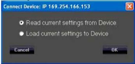
Fig. 4
To initiate a Project set-up, click on "Read current settings from Device" to start, then change any parameters you want to alter.
You can use the Copy Device function (D1) to copy the changed parameters to the other cabinets in the array as appropriate, make any other changes to any of the other cabinets one at a time in the array (amplitude shading, frequency shading, etc.) or load in of one of the MLAS™ Presets. Once all the parameters for all the cabinets in the array have been changed to the desired settings, then Save the project.
F2
Save Project
Save's a Project file to the PC software Project Folder
Click on the Save File icon (F2) to open a standard Windows file dialog window.
The default folder will be the Project folder in the VR Series v1.2.X folder, which is generally located on the root drive of the PC, the exact location which is dependent on your operating system version. During any given session, you can change the folder where the files are saved to, or read from, but the default Save location on start up of a new instance of the GUI software will always be the folder named Project.
F3
Load Project
Load's a Project file from the PC software Project folder
The Project file can only be loaded into a group of cabinets using the same cabinet ID's as were present when the Project was first created. If you attempt to load a Project file into a cabinet that was NOT a part of the original cabinets that were present on the DSP GUI network, then the saved parameters associated with a Project file will not transfer over to that new cabinet, and this may disrupt the proper loading of any other cabinets that were present at the time the original Project file was created.
The Project Files store and load all the parameters in all the Pages for a given device/cabinet, but unlike the Preset files, the Project file also saves the parameters that are found under the Settings icon, #4 on Fig. 7. These parameters are not loaded or changed when a Preset is loaded or saved. For a list of what those parameters are, see View Page, Section 4, Fig 14 and subsequent content.
Remember, a Project file only works with the exact same cabinets that were present when the Project was created.
Loading Projects from PC GUI software folders
- Position the View page from Fig. 6 so it does not cover up the row of icons at the top left corner of the Start page, but still has the bottom portions of the View page visible.
Click on icon F3, from the Start page (Fig.2), Load Project.
- The "Load Project" dialog window will come up, see Fig. 19

Fig. 19
Click Yes.
- A file manager window will come up with the File Folder contents for the Project files, located at: For Windows 7 and for Windows XP - C:\Program Files (x86)\VR Series v1.2.X\Project For Windows 10 - C:\Program Files\VR Series v1.2.X\Project. No (x86) where C: is the root drive where the Versarray™ Pro series User GUI PC software has been located, and "X" is the version of the software you have loaded onto the PC.
You must pick a previously saved Project file, as there are no supplied Factory Project files, they must be associated with the exact cabinets present on the network at the time of the Project save. Let's say you named a Project file "Example-1"
Highlight and Click "OPEN" on the Example-1 Project file.
- The "LAN Device Discovery" window will come up. See Fig. 20

Fig. 20
Click on "Yes".
- The Connect Device dialog window comes up, as shown in Fig. 21.
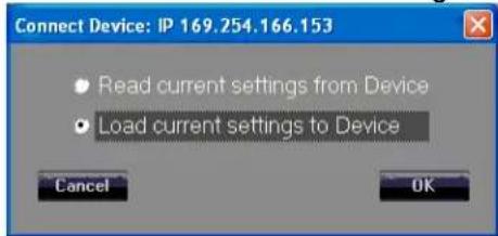
Fig. 21
Click on "Load Current Settings to Device"
Once the settings have been loaded into the VR112 speaker system, the Device List should now show one or more of the units as "On-line", See Fig. 5 in the previous section on Presets, where the arrow points.
- Double-click on the desired unit in the NAME column in that row, shown by the "X" in Fig. 5, and the View page will come up as shown in Fig. 6.
CAUTION: After loading a Project into an array of VR PRO models, look at the View page, and the other pages for that cabinet/device, to make sure that the desired parameters have loaded in, and that crossovers, and EQ are present. This will require paging through the Input page, and the Output page/High Output - Low Output pages to make sure that the curves shown are not all flat with no crossover action or EQ present.
IF THE VR112 IS OPERATED WITHOUT ANY CROSSOVERS ACTIVE, OR WITHOUT ANY EQ, IT IS LIKELY THAT THE RIBBON TWEETERS WOULD BECOME DAMAGED, so it important to check the individual pages of each device/cabinet to make sure all the parameters have loaded in properly.
F4
Add Group
Contact Crest Audio® for details on this function, or check the Crest Audio® website for more information:
https://peaveycommercialaudio.com/versarray
M1
Store Program
Allows multiple cabinets to have a Preset File stored to memory, see Fig. 22
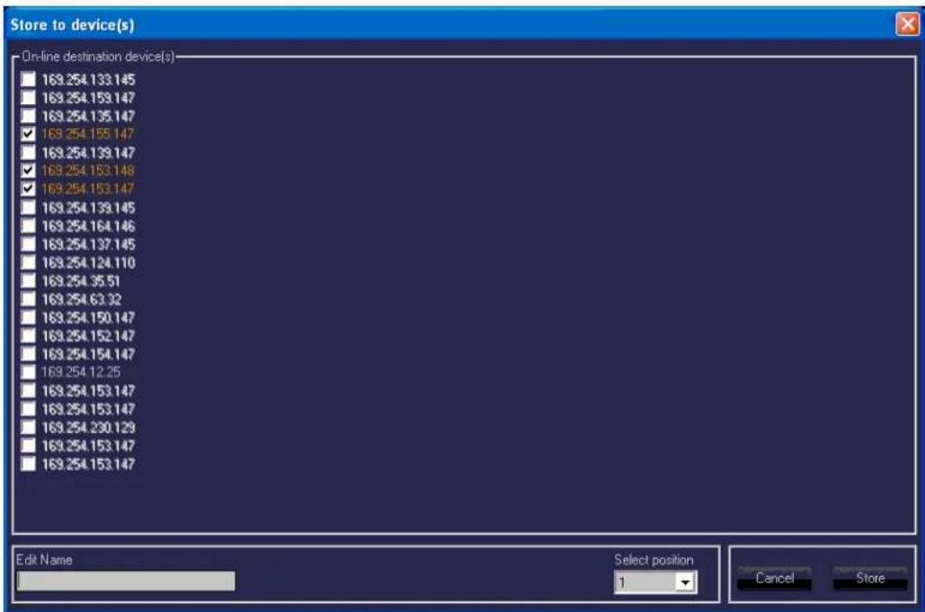
Fig. 22
All the cabinets currently connected online to the Versarray™ Pro series User GUI Software network are shown grayed out, other cabinets that may have been connected at one time are listed with white letters. The IP address for a particular cabinet can be determined by looking at the Device List of Fig. 2, which also lists the assigned Net ID number, as well as the Name of the device and the Unique ID number.
Once the online devices have been check box selected for "Store to device(s)", the network IP addresses turn orange. Choose a Name for the file to be loaded, make a "Select position" choice for the onboard DSP memory location (one through ten of 10 Preset storage slots), and then click on the
"Store" button.
These cabinets must all be of the same type, i.e., all VR 112's or all VR 215's, etc.
M2
Recall Program
Similar to Storing multiple devices, one can Recall from a list of multiple device, however, you can only retrieve one Preset file at a time. See Fig. 23.
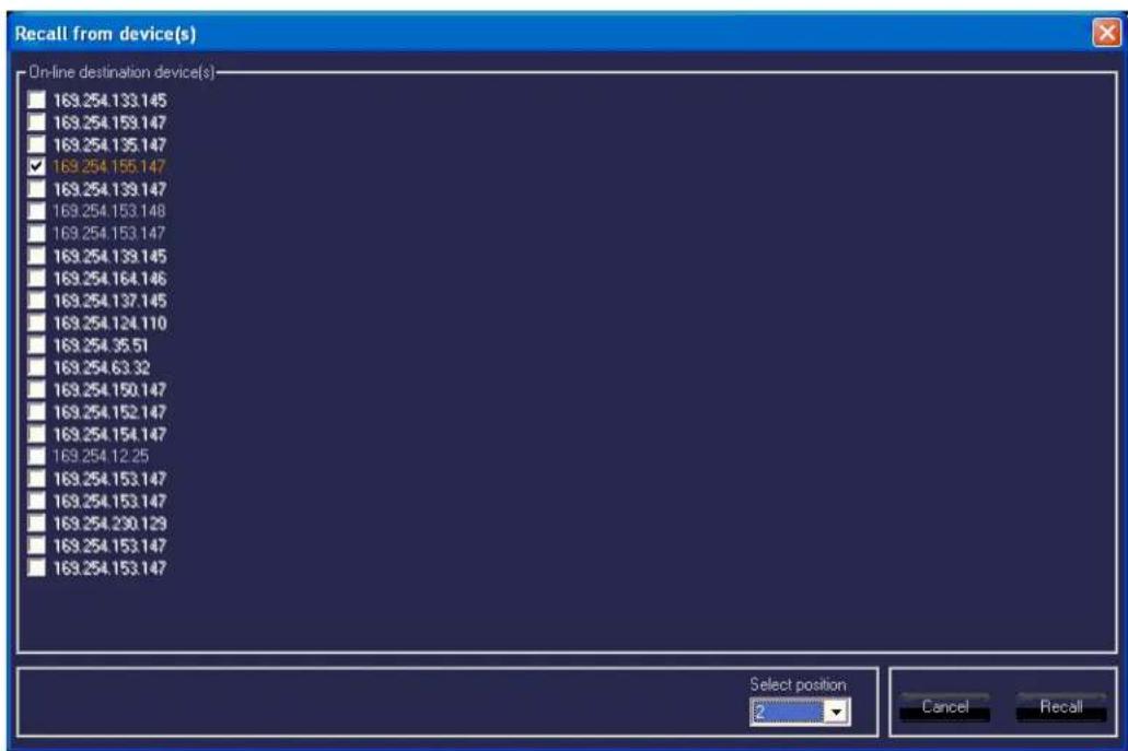
Fig. 23
Select the online device to have the Preset file Recalled, and click the check box for that device. Select the memory position to be Recalled, (one through ten of 10 Preset storage slots), and click the "Recall" button.
The Preset that was previously loaded into memory at that location will now be loaded into the units DSP preamp and change the parameters of the various pages to those Preset settings.
Line Array Device Management
The Device List, D∅, has several columns of information displayed.
The columns labeled IP, NAME, and NET ID are able to be changed and altered using the Settings Icon, Section 4 of the View Page. See that Section for details.
The NET ID can also be changed using the rear panel buttons shown on the Rear Panel Display at (11) Assign Network I.D. Buttons. If using the rear panel buttons to change the Network I.D., do so before establishing network connection, otherwise, once connected, use the GUI to make any changes.
D1
Copy Device
Copies the parameters of a highlighted device in the Device List D∅ to another device or devices in the Device List. See Fig. 24
NOTE: Do not attempt to copy a VR 112 Preset into a VR 215 or VR 218 Sub, copy the Presets from a given model into the same model.

Fig. 24
D2
Connect All Devices
Establishes connection with all networked devices sequentially, and displays the connections in the Device List.
D3
Disconnect All Devices
This disconnects all the On-line devices listed in the Device chart, and takes them Off-line from the network.
D4
Add Device
Adds a new device to the Device List, one unit at a time.
D5
Remove Device
As above, only removal of one device from the Device List.
D6
Search Devices
Initiates a search for devices connected to the Versarray™ Pro series User GUI Software network. Must use the proper search parameter (IP address) in order for the software to detect devices connected to the network.
Preset Files Available for Use
Ten On-board Presets
- Single_Cab_Flat (Default or Factory Loaded)
- 2Cabs_Mild_Angle (2.5 to 5 degrees)
- 3Cabs_Mild_Angle
- 4Cabs_Mild_Angle
- 6Cabs_Mild_Angle
- 8Cabs_Mild_Angle
- 2Cab_More_Angled (7.5 to 10 degrees)
- 3Cab_More_Angled
- 4Cab_More_Angled
- 6_Cabs_More_Angled
These first ten Presets are loaded into the power amp DSP memory, and are accessed directly using the Section A Store and Recall functions. File versions are also stored in the PC software DSP GUI Preset folder.
Preset files included in PC software DSP GUI Preset folder
- 2cabs_Straight-line (0 degrees angle between cabs)
- 3cabs_Straight-line
- 4cabs_Straight-line
- 6cabs_Straight-line
- 8cabs_Straight-line
- 2Cabs_J-line_section (angles of 12.5 to 15 degrees)
- 3Cabs_J-line_section
- 4Cabs_J-line_section
- LT_2Cabs_Mild_Angle (LT is Long Throw)
- LT_3Cabs_Mild_Angle
- LT_4Cabs_Mild_Angle
- LT_6Cabs_Mild_Angle
- LT_8Cabs_Mild_Angle
- BB_2Cabs_Mild_Angle (BB is Bass Boost)
- BB_3Cabs_Mild_Angle
- BB_4Cabs_Mild_Angle
- BB_6Cabs_Mild_Angle
- BB_8Cabs_Mild_Angle
- BB_2Cab_More_Angled
- BB_3Cab_More_Angled
- BB_4Cab_More_Angled
- BB_6Cab_More_Angled
- BB_2cabs_Straight-line
- BB_3cabs_Straight-line
- BB_4cabs_Straight-line
- BB_6cabs_Straight-line
-
BB_8cabs_Straight-line
-
BB_2Cabs_J-line_section
- BB 3Cabs J-line section
- BB_4Cabs_J-line_section
FILES LOADED INTO POWER AMP MEMORY, ALSO IN GUI FOLDER, FOR WHEN THEY GET OVERWRITTEN IN AMP MEMORY.
- Single_Cab_Flat
- 2Cabs_Mild_Angle
- 3Cabs_Mild_Angle
- 4Cabs_Mild_Angle
- 6Cabs_Mild_Angle
- 8Cabs_Mild_Angle
- 2Cab_More_Angled
- 3Cab_More_Angled
- 4Cab_More_Angled
- 6_Cabs_More_Angled
DSP GUI Preset Folder files for SUBS (included in this folder for when the Subs are being run under the PC DSP GUI software, as they use the same default folder name)
VR218 Nominal
VR215 Nominal
VR218 BassBoost
VR215_BassBoost
NOTE: DO NOT ERASE OR DELETE ANY OF THE FACTORY PRESET FILES FROM THE PC FOLDER, OR WRITE OVER THEM IN THE PC SOFTWARE FOLDERS WITH A CUSTOM SETTING WITHOUT CHANGING THE NAME.
Even if you do not plan to use the Crest Audio® MLAS™ technique at this time, you may find a use for it or it's files later, or want to experiment with the files in the future.
Crest Audio® will provide copies of the Preset files, and updates of same at the Crest Audio® website at:
https://peaveycommercialaudio.com/versarray
New Folders can be created in the User GUI software location, with your own custom Presets saved into that folder. At start-up, the User GUI software by default will always look for the Folders named "Preset" or "Project", but you could perform some file manipulation and copy all of the stock Factory MLASTM files into a newly created Folder called "Backup", and then alter the files in the "Preset" folder at will.
For the latest up to date Owner's Manual's, Preset files, and other information about the Versarray ^™ Pro system check out:
https://peaveycommercialaudio.com/versarray
THIS SPEAKER SYSTEM CAN PERMANENTLY DAMAGE HEARING! USE EXTREME CARE IN SETTING THE MAXIMUM LOUDNESS!
LOSS OF LAN NETWORK CONNECTION
If you experience a loss of the LAN network connection to one or more of the VR speaker systems while operating the Versarray ^TM Pro system's PC DSP GUI software, an error message will be generated.
See Figure 25 below.

FIG. 25
This can occur due to momentary loss of the LAN connection, a faulty Ethernet RJ45 plug or jack, packet loss, or other common network problems.
While the Versarray ^™ Pro system's PC DSP GUI software runs without issues alongside Dante on a LAN, Dante has a very robust recovery capability, and may maintain connectivity despite any intermittent network connections.
If this occurs, then to reconnect the PC with the VR unit, click OK on the error message click button. If the connection has re-established itself without further errors, then a dialog Window will pop-up, as shown below in Fig. 3.

Fig. 3.
You can then click on OK to re-connect as it normally progresses upon initial start-up and connection.
However, if the connection was not re-established due to network conditions, the following error message may pop-up, as shown below in Fig. 26

Fig. 26
If this is the case, then close the Versarray ^TM Pro system's PC DSP GUI software window by clicking on the Close box in the upper right hand corner, and then Yes on the Exit box click button. See Fig. 27 below.

Fig. 27
Then once the software has closed, allow enough time for the network connection to re-establish, this will typically take as long as it normally does when you first connect, however long your particular system takes to do that. This can be up to a minute or more.
Then start the VR PC DSP GUI software again.
If you continue to get error messages or the Unreachable error (Fig. 26), then the network cables, connectors, and such will all need to be checked for correct insertion and continuity.
It may be necessary to re-boot the computer if the problem persists after all the cables and connectors check out OK. This should be done in conjunction with cycling the power to the Versarray ^™ Pro speaker system's.
Design and specifications subject to change without notice.
NOTE: Before you fly the array, be sure to inspect the rigging and flying hardware to insure that it is mechanically sound and has not been damaged, there should be no significant distortion of the shape of the coupling brackets, cabinet brackets, Halo or fly bar, and the hardware should be checked for tightness.
This Crest loudspeaker should be suspended overhead only in accordance with the procedures and limitations specified in the User's Manual and possible manual update notices. This system should be suspended with certified rigging hardware by a qualified rigging professional and in compliance with local, provincial or national suspension ordinances. ALWAYS USE PROPER GRADE HARDWARE.
CAUTION: Before attempting to suspend this speaker, consult with a certified structural engineer. Speaker can fall from improper suspension, resulting in serious injury and property damage. Use only the correct mating hardware. All associated rigging is the responsibility of others. Maximum enclosure angle 30 degrees. Failure to follow proper rigging specifications listed in the manual may result in injury or death.
Whenever possible, in addition to the nominal primary mounting method, use a suitable safety chain or wire rope attached to one of the other groups of fly points, and firmly attached to a suitable structural member as indicated by a certified structural engineer. CAUTION: ALWAYS USE SAFETY CHAIN OR WIRE ROPE. It is the responsibility of the user and installer to make sure that any Crest Audio® Versarray™ installation meets any applicable local, state or federal safety regulations.

IF ANY OF THE RIGGING, OR THE HALO OR FLY BAR HAS BEEN DAMAGED OR DISTORTED, DO NOT USE, AND DO NOT FLY THE ARRAY UNTIL THEY CAN BE REPLACED OR REPAIRED!
DO NOT USE THE PIVOT BAR OR ANGLE SLIDER BRACKET AS HANDLES TO TRANSPORT THE CABINETS!
DO NOT TRANSPORT THE CABINETS IN ARRAY CONFIGURATION COUPLED TOGETHER, EXCEPT WITH THE RECOMMENDED TRANSPORT CART AND IN THE STIPULATED MANNER FOR THAT CART. TRANSPORT IN SUCH AN UNAPPROVED MANNER VOIDS THE WARRANTY, AND THE SYSTEM WOULD BE CONSIDERED UNSAFE TO BE FLOWN AFTER SUCH AN UNAPPROVED TRANSPORT EVENT.
Use only the correct mating hardware. All associated rigging is the responsibility of others.
Correct use and seating of the Quick Release Push Lock Pins Used with all Versarray ^™ rigging hardware
When using the Quick Release Positive Lock Pins, when the Quick Release Push Lock Pins are inserted, they should be fully seated, so that the black shoulder near the end of the pin has been placed flush with the side of the bracket, or as far in as the pin hole cavity will allow it to be inserted.
You will have to fully depress the center push-button to do this.
You should not be able to pull these pins out unless the center push-button is fully depressed.
Versarray™ Mk3 Halo Use
Specific Instructions for flying and hanging the Versarray™ Mk III Halo will not be supplied. It provides and follows industry standards for attaching rigging and fly hardware, as well as providing for the currently popular practice of hanging the array via a single hang point that can be a suitably rated chain hoist motor system. Seek the recommendations of a certified structural engineer or an experienced rigging professional for any questions about this type of use of the Versarray™ Mk III Halo.
Instructions for maximizing the single point hang balance point options are provided in the Versarray™ Mk3 Halo Owner's Manual, due to the unique flexibility the Versarray™ system provides.
Hanging Versarray™112 Mk III Cabinets from a Versarray™ Mk III Halo
Assuming the Halo is in position just above the cabinet/s, on a motorized hoist or manually cranked hoist, proceed as follows.
- Remove the top front quick release lock pins, slide the front hang straps up and pin them in place using those pins, with the front hang straps extending upward. The strap should be sticking up approximately 2.13". Do this for both sides. See Fig.1 and 1a.
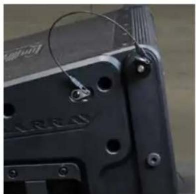
natural_image
Close-up of a black electronic component with mounting holes and wires (no visible text or symbols)Figure 1

natural_image
Close-up of a black mechanical component with mounting holes and a wire, no visible text or symbolsFigure 1a
Cabinet Hang
Strap
- Either lower the Versarray™ Mk III Halo to meet the cabinet, or raise the cabinet up to meet the Halo, with the cabinet straps guided into mating with the Halo ears on both sides at the same time. Pin the front straps in place using the pins from the Halo. See Fig. 2

Figure 2
- Remove the Pivot Bar hole pin, swing pivot bar up to mate with the center rear bottom Halo ear hole. The bottom hole on the Halo ear provides a zero angle between the Halo and the first cabinet, the upper hole an angle of 5 degrees between the Halo and the first cabinet. Pin the Pivot Bar to the desired hole using the pin from the Halo. See Fig. 3

Figure 3
- Adding the second Cabinet.
Remove the top front quick release lock pins, slide the front hang straps up and pin them in place extending upward. The strap should be sticking up approximately 2.13". Do this for both sides. See Fig.1 and 1a.
- Either lower the Halo and first cabinet to meet the second cabinet, or raise the second cabinet up to meet the first cabinet, with the second cabinet straps guided into mating with the first cabinet bottom strap slots. Pin the front straps in place using the pins from the first cabinet. See Fig. 4 and 4a.
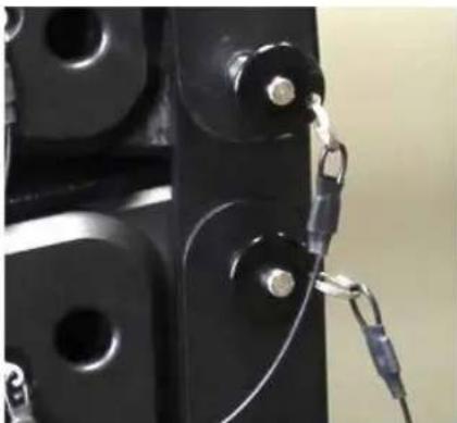
natural_image
Close-up of a black mechanical component with metallic hardware and metal clamps (no visible text or symbols)Figure 4 Figure 4a

- Remove the Pivot Bar hole pin on the second cabinet, swing pivot bar up to mate with the Pivot Bar hole of the first cabinet. Pin the Pivot Bar into place using the bottom rear pin on the first cabinet. See Fig. 5 and 5a.
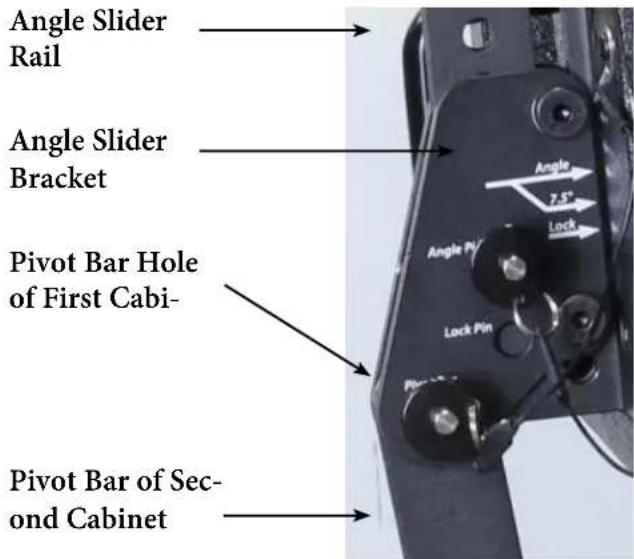
Figure 5

Figure 5a Alternate View

NOTE: Once the Pivot Bar hole pin is removed, the cabinet is free to swing through all possible angles, be sure to keep fingers, hands and your body out of the possible path of the cabinet hardware or the cabinet itself, to avoid injury.
With the first cabinet rigging in the default factory Lock position, that is, with the Angle Slider bracket lined up with it's arrow at LOCK, lined up with the LOCK arrow on the Angle Slider Rail, the angle between the first and second cabinets is not at a nominal set angle, it is an intermediate setting.
The angle the cabinets are set to can be read at the Angle arrow.
- The angle of the second cabinet can now be adjusted. To set the angle between the first cabinet and the second cabinet to a nominal amount, remove the Lock pin from the hole it is in, and slide the Angle Slider bracket. Angle Arrow to the desired angle as shown by the arrow labeled Angle on the Angle Slider Rail, and put a pin from the first cabinet (the one you removed from the Lock hole) into the Angle Pin hole on the Angle Slider bracket.
You can set the angle between the first cabinet and the second cabinet to be any of the following angles: 0 degrees, 2.5 degrees, 5 degrees, 7.5 degrees, 10 degrees, 12.5 degrees, and 15 degrees As an example, see See Fig. 6, showing a set angle of 2.5 degrees.

Figure 6
The angle for 7.5 degrees uses a different set of arrows, due to the hardware bolt being in the way of a correctly located screened angle on the Angle Slider Rail using the Angle arrow on the Angle Slider bracket.
This is why there is an arrow that is an offshoot of the Primary Angle arrow on the Angle Slider bracket, just below it, labeled 7.5 degrees. This is lined up with the arrow marked 7.5 degrees on the Angle Slider rail. See Fig. 7.

Figure 7
Adding additional cabinets follows this same basic hook-up progression, with the Angle Slider on the top cabinet of a given pair setting the angle between those two cabinets.
NOTE: Any Versarray™ Sub cabinets that might be flown in the same array off of the same Halo should be located at the top of the array, as they have no angle adjustment capability, and can only be hung at a 0 degree angle.
Alternate Method of Setting Angles Between Cabinets
Instead of following Step 6 (Hook-up Pivot Bar) and then Step 7 (Set Angle Between Cabinets), set the angle on the Angle Slider bracket and rail before un-pinning the Pivot Bar, and connecting it to the previous cabinet. Each method will work, but one will be more easily implemented with one person setting up the rig, versus having two or more people available.
Dismantling an Array
To take the line array down, you simply reverse the process, and remove one cabinet at a time, placing the rigging hardware into the nominal storage and transport positions.
Retract all the hang straps, and pin into place, place the Pivot Bar into the proper position to pin it into the Pivot Bar Hole, remove the pin from the Angle Pin hole, and slide the Angle Slide bracket into the LOCK position (LOCK arrow lined up with the other LOCK arrow), and pin into place. See Fig. 8.

Figure 8
Make sure that all the quick release lock pins are re-inserted into their default positions.
Cabinet hardware and rigging must be placed into the storage and transport positions, to move or transport the cabinets individually, or the product Warranty is voided.
The only exception is use of the Crest Audio ^® designed transport Carts, capable of transporting 3 Versarray ^™ Pro 112s while in a straight line array configuration, with all cabinets set to 0 degrees. Instructions for the proper use of the Cart will be in the Cart Owner's manual.
INFORMATION ON THE FLYING HARDWARE FOR THE Versarray™ Pro 112 (Available Separately)
CAUTION! Before attempting to suspend any Versarray™ Rigging Hardware with or without speakers hung from it, consult a certified structural engineer. The Halo/Fly Bar and/or speaker array can fall from improper suspension, resulting in serious injury and property damage. Use only the correct mating hardware. All associated rigging is the responsibility of others.
This Crest loudspeaker should be suspended overhead only in accordance with the procedures and limitations specified in the User's Manual and possible manual update notices. This system should be suspended with certified rigging hardware by an authorized rigging professional and in compliance with local, provincial or national suspension ordinances.
Whenever possible, in addition to the nominal primary mounting method, use a suitable safety chain or wire rope attached to one of the other groups of fly points, and firmly attached to a suitable structural member as indicated by a certified structural engineer. CAUTION: ALWAYS USE SAFETY CHAIN OR WIRE ROPE.
Crest Audio® Versarray™ Mk III Halo Crest FG# 03617370
Connects Versarray ^™ 112 and Versarray ^™ Pro 215 Sub speakers to overhead rigging.
Provides four M20 X 2.5mm thread forged steel eyebolts for traditional rigging on the top of the Halo; Halo center bar has 7 single-point hang locations to balance the Halo, and an optional 2 foot fly bar increases the number of separate and distinct balance points to 29. Includes quick-lock pins to mate to the first VR112 cabinet in a line.
Includes the bolts for the optional 2 foot or 6 foot Fly Bar.
Specifications:
Overall Dimensions, Including Pins and Eyebolts, etc. H x W x D:
11.63" X 27.44" X 20.63" (29.5 cm X 69.7 cm X 52.4 cm)
Halo Only Dimensions H x W x D:
11.63" X 25.50" X 20.63" (29.5 cm X 64.8 cm X 52.4 cm)
Weight: 64 lbs.
Material: All steel construction, 2" by 3" welded steel frame tubing with 3/16" wall thickness, center bar 1 / 2 " thick by 3" solid steel with seven 23mm rigging holes along the center of it's length, Halo coupling mounts for the cabinet front hang straps are dual 1/8" thick steel plates, one pair on each side.
Finish: Entire Halo is flat black powder coated paint finish.
Working Load Limit: 544 kg / 1,200 lbs. for Ultimate Strength Design Factor of 10:1
(This meets PLASA North America criteria and typically exceeds local USA safety requirements.)
Working Load Limit: 453 kg / 1,000 lbs. for Ultimate Strength Design Factor of 12:1
(This is in compliance with the European Union mandated Safety Factor)
Maximum Number of Versarray™ 112 Mk3 passive cabinets: 15
Maximum Number of Versarray ^™ Pro 112 Powered cabinets: 15
Maximum Number of Versarray™ Pro 215 Sub cabinets: 7 for North America (PLASA), 6 for European Union
(Note: VR215 Pro Sub cabinets do NOT articulate or angle, they must be hung at a zero degree angle. Therefore, we recommend that they be hung at the top of a line.)
Can fly up to 7 Versarray™ Pro 215 Subs, or 15 Versarray™ 112 Mk3 or Pro 2-Ways
Maximum Combined Number of Versarray™ Pro 112 2-Ways and Versarray™ Pro 215 Sub cabinets:
MIX OF SUBS VERSUS VR Pro 112
Subs VR Pro 112
| EU | N. | America | ||
| 0 | 12 | 15 | ||
| 1 | 9 | 11 | ||
| 2 | 7 | 9 | ||
| 3 | 5 | 7 | ||
| 4 | 3 | 5 | ||
| 5 | 1 | 3 | ||
| 6 | 0 | 1 |
7* X 0 *N. America (PLASA) ONLY!

WARNING!
Crest Audio ^® is not liable for any injuries or damages that could potentially occur if the specified Working Load Limit is exceeded for any of the Versarray ^™ FlyQWIK ^™ rigging components or system configurations.
If there is any question about the capacity of a given configuration of rigging hardware and cabinets, you should consult with a certified structural engineer or a qualified rigging professional before installing the system.
Maximum Combined Pull-Back Angle, Two or less Subs in the hang: 30 degrees Maximum Pull-Back Angle, more than 2 Subs in the hang: 15 degrees
NOTES:
The ultimate strength for the Versarray™ Mk3 loudspeaker system rigging hardware was determined utilizing calibrated and certified pull tests.
Maximum number of cabinets was determined using all loading and safety criteria, not just the simple weight of the cabinets versus the WLL of the Halo.
More complete information on the Crest Audio® Versarray™ FlyQWIK™ Rigging System and the Mk III Halo can be found in the unit's Owner's manual, or by contacting Crest Audio*.
Design and specifications subject to change without notice.

WARNING!
IMPORTANT INFORMATION FOR STRUCTURAL ENGINEER AND RIGGING PERSONNEL.
Before you fly the array, be sure to inspect the rigging and flying hardware to insure that it is mechanically sound and has not been damaged. There should be no significant distortion of the shape of the Halo coupling ears, cabinet straps, Angle Slider bracket or Rail, Pivot Bar or a fly bar, and the hardware should be checked for tightness.
CAUTIONS:
IF ANY OF THE BRACKETS, RAILS, CABINET STRAPS, PIVOT BAR OR THE FLY BAR HAS BEEN DAMAGED OR DISTORTED, DO NOT USE, AND DO NOT FLY THE ARRAY UNTIL THEY CAN BE REPLACED OR REPAIRED!
DO NOT USE THE PIVOT BARS AS HANDLES TO TRANSPORT THE CABINETS!

natural_image
Technical line drawing of a mechanical device housing with internal components and mounting brackets (no text or symbols)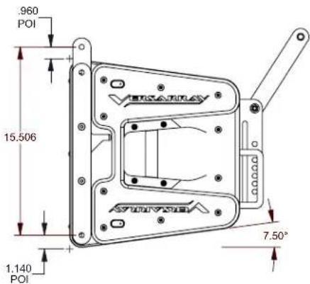




FCC/ICES Compliancy Statement
This device complies with Part 15 of the FCC. Operation is subject to the following two conditions: (1) this device may not cause harmful interference, and (2) this device must accept any interference received, that may cause undesired operation.
Warning: Changes or modifications to the equipment not approved by Peavey Electronics Corp. can void the user's authority to use the equipment.
Note – This equipment has been tested and found to comply with the limits for a Class A digital device, pursuant to Part 15 of the FCC rules. These limits are designed to provide reasonable protection against harmful interference when the equipment is operated in a commercial environment. This equipment generates, uses and can radiate radio frequency energy and, if not installed and used in accordance with the instruction manual, may cause harmful interference to radio communications. Operation of this equipment in a residential area is likely to cause harmful interference in which case the user will be required to correct the interference at their expense.
Architectural and Engineering Specifications
The 2-way Bi-Amplified Ribbon Line Source Array loudspeaker system shall have an operating bandwidth of 100 Hz to 20 kHz, measured on axis at 1 meter in an anechoic environment, with +3/- 6 dB tolerance. The maximum peak output level shall be 130 dB for the low frequencies, and 131 dB for the high frequencies when measured at a distance of one meter with full system output. The woofer loaded into the cabinet shall be a Peavey® Neo Black Widow® 12" 8 ohm woofer. The tweeter drivers shall be two Peavey® RD™ 2.6 MK III Ribbon Tweeters loaded onto a CLEAR FORM™ Waveguide.
The bi-amplified speaker amplifiers shall have a total power output of 3400 watts peak, and the power amps shall be fan cooled. Signal input shall be provided via XLR analog and Dante® Ethernet connections. The analog output Thru connector shall be a male XLR for daisy-chaining to the next cabinet as needed.
DSP signal processing shall be incorporated to provide the crossover, protective filtering and EQ for the system, as well as limiting and compression to minimize overdrive distortion.
The cabinet shall incorporate rigging hardware to interface with the Crest Audio® Versarray™ FlyQWIK™ rigging system, including the Crest Audio® Versarray™ VR Mk III Halo.
The outside dimensions shall be 15.13 inches high by 25.06 inches wide by 15.19 inches deep. The weight shall be 75 pounds. The loudspeaker system shall be a Crest Audio ^® model Versarray ^™ Pro 112.

FCC/ICES Compliancy Statement
This device complies with Part 15 of the FCC. Operation is subject to the following two conditions: (1) this device may not cause harmful interference, and (2) this device must accept any interference received, that may cause undesired operation.
Warning: Changes or modifications to the equipment not approved by Peavey Electronics Corp. can void the user's authority to use the equipment.
Note – This equipment has been tested and found to comply with the limits for a Class A digital device, pursuant to Part 15 of the FCC rules. These limits are designed to provide reasonable protection against harmful interference when the equipment is operated in a commercial environment. This equipment generates, uses and can radiate radio frequency energy and, if not installed and used in accordance with the instruction manual, may cause harmful interference to radio communications. Operation of this equipment in a residential area is likely to cause harmful interference in which case the user will be required to correct the interference at their expense.

www.peaveycommercialaudio.com Warranty registration and information for U.S. customers available online at www.peaveycommercialaudio.com/warranty or use the QR tag below

Features and specifications subject to change without notice. Crest Audio 5022 HWY 493 N. Meridian, MS 39305 (601) 483-5365 FAX (601) 486-1278

Lags referenced in Directive 2002/08/EC Annex IV (CJ) 67/58-19.02.03 and defined in FN 504-19. 2005 The bar is the symbol for marking of new waste and is applied only to equipment manufactured after 13 August 2005


- Versarray™ Pro 112 Powered Enclosure Product Specifications
- CREST AUDIO
- Features
- SPECIFICATIONS
- Versarray PRO 112
- Rear Panel Controls and Connections
- System Settings Group
- Sensitivity Buttons
- Array Count Button
- HF Boost Button
- Low Mid Button
- Audio Group
- Network Group
- Primary Ethernet IN, RJ45 jack Secondary Ethernet in/out, RJ45 jack
- Assign Network I.D. Buttons
- Power Group
- Volume Buttons
- Sensitivity Buttons
- Array Count Button
- HF Boost Button
- Low Mid Button
- Analog Audio Group
- IN
- OUT/THRU
- Making Audio Connections
- ON/OFF POWER SWITCH with BLUE LED
- Dante Operation
- Horizontal Polar Patterns
- Ribbon Tweeter Warnings and Cautions
- Frequency Response
- Directivity
- Crest Audio ® MLAS ™ technique
- Part 1
- Selecting the Line Array Geometry
- What Constitutes a "Real" Line Array?
- Aiming the Line Array
- Example of Using the MLAS™ Technique
- Vertical Coverage Angles of Various Section Presets
- Preset: Single\_Cab\_Flat
- Preset: 2cabs\_Straight-line
- Coverage Plotting Using Floor Plans
- Tweaking the Array for Best Performance
- Amplitude Shading
- Frequency Shading
- Venue EQ
- Bass Boost Preset Use
- Level Matching with the Versarray™ VR218 and 215 Pro Subs
- Crest Audio® Versarray™ Pro series - User GUI Use Instructions
- Connecting the User GUI Software to the Versarray™ Pro 112 Speaker System for Analog Signal Input Use
- THE MOST COMMON CAUSE OF A FAILURE TO CONNECT TO THE POWER AMP MODULE VIA THE NETWORK IS NOT ALLOWING ENOUGH TIME FOR THE PC TO MAKE THE NETWORK CONNECTION CORRECTLY BEFORE STARTING THE SOFTWARE!!
- Using the Versarray™ Pro series User GUI Software with the Versarray™ Pro 112
- Quick Start Instructions
- CAUTION!
- WARNING!
- USE OF SETTINGS OTHER THAN THE FACTORY SETTINGS FOR FUNDAMENTAL PARAMETERS WILL VOID THE WARRANTY!!
- Quick Start Instructions, CONT'D
- Loading Presets from PC GUI software folders
- Full List of Features of the Versarray™ Pro series PC Software GUI Pages for the Versarray™ Pro 112
- View Page
- Preset File Management Group A
- Signal Flow Chart Group B
- Section 1
- Section 2
- Section 3
- Section 4
- Fig. 11
- NAME
- AUTO-SLEEP
- AUTO-STANDBY
- INP HEADROOM
- NETWORK ID
- HF BOOST
- ARRAY COUNT
- LOW MID
- Setting a Cabinet Up for Network Use Only
- Section 5
- FW Update
- Section 6
- Identify
- Section C
- Volume
- Section D
- Sensitivity
- Section E
- Section F
- Section G
- Section H
- Section J
- Section K
- Section 7
- Section 8
- Section 9
- Section 10
- Section 11
- Section 12
- Section 13
- Input Page
- Section 14
- Section 15
- Noise Gate
- parameters
- Release
- Attack
- Section 16
- FIR
- Section 17
- Section 18
- Section 19
- CHANGING THE BANDS WITH FACTORY SETTINGS MAY VOID THE WARRANTY!
- Section 20
- Section 21
- Section 22
- Section 23
- Section 24
- Section 25
- Section 26
- RMS Compressor Section
- Lows Output Page
- Section 27
- Section 28
- EQ Filters
- Section 29
- RMS Compressor
- Section 30
- Peak Limiter
- Section 31
- Hard Lim
- Parameter
- Indicator
- Section 32
- Section 33
- Section 34
- Section 35
- Section 36
- Section 37
- Section 38
- Section 39
- Section 40
- Section 41
- Section 42
- Highs Output Page
- Section 43
- Section 44
- Section 45
- Section 46
- Section 47
- Section 48
- Section 49
- Section 50
- Section 51
- Section 52
- Section 53
- Section 54
- Section 55
- Section 56
- Section 57
- Section 58
- Using the Non Network Push-Buttons On the VR112 Rear Panel
- Low-Mid
- PROJECT/PRESET FILE MANAGEMENT
- Project File Management
- F1
- F2
- F3
- Loading Projects from PC GUI software folders
- F4
- M1
- M2
- Recall Program
- Line Array Device Management
- D1
- D2
- D3
- D4
- D5
- D6
- Preset Files Available for Use
- Ten On-board Presets
- Preset files included in PC software DSP GUI Preset folder
- FILES LOADED INTO POWER AMP MEMORY, ALSO IN GUI FOLDER, FOR WHEN THEY GET OVERWRITTEN IN AMP MEMORY.
- DSP GUI Preset Folder files for SUBS (included in this folder for when the Subs are being run under the PC DSP GUI software, as they use the same default folder name)
- LOSS OF LAN NETWORK CONNECTION
- Correct use and seating of the Quick Release Push Lock Pins Used with all Versarray ™ rigging hardware
- Versarray™ Mk3 Halo Use
- Hanging Versarray™112 Mk III Cabinets from a Versarray™ Mk III Halo
- Alternate Method of Setting Angles Between Cabinets
- Dismantling an Array
- INFORMATION ON THE FLYING HARDWARE FOR THE Versarray™ Pro 112 (Available Separately)
- NOTES:
- CAUTIONS:
- Architectural and Engineering Specifications
Brand : CREST AUDIO
Model : Versarray PRO 112
Category : Loudspeaker