
NIM-40B - Home Automation Aiphone - Free user manual and instructions
Find the device manual for free NIM-40B Aiphone in PDF.


| Product Type | Video Door Station |
| Brand | Aiphone |
| Model | NIM-40B |
| Dimensions (HxWxD) | 120 x 80 x 30 mm |
| Weight | 200 g |
| Power Supply | 24 V DC, 500 mA |
| Display | 4.3-inch TFT color LCD |
| Camera | 1/4-inch CMOS, 640x480 resolution |
| Audio | Full-duplex hands-free communication |
| Connection | 2-wire analog or digital (depending on system) |
| Main Functions | Audio/Video calling, door release, night vision, intercom |
| Mounting | Surface or flush mount |
| Protection Rating | IP54 (weather resistant) |
| Operating Temperature | -10°C to 50°C |
| Maintenance | Clean with dry cloth; avoid solvents |
| Safety | Low voltage, surge protected |
| Spare Parts | Available from Aiphone authorized dealers |
| Repairability | Modular design, user replaceable camera module |
| Compliance | CE, RoHS |
| Warranty | 2 years (depending on region) |
Frequently Asked Questions - NIM-40B Aiphone
User questions about NIM-40B Aiphone
0 question about this device. Answer the ones you know or ask your own.
Ask a new question about this device
Download the instructions for your Home Automation in PDF format for free! Find your manual NIM-40B - Aiphone and take your electronic device back in hand. On this page are published all the documents necessary for the use of your device. NIM-40B by Aiphone.
USER MANUAL NIM-40B Aiphone
natural_image
Line drawing of a classic office telephone with keypad and cord (no text or symbols)The illustration shows the * Master station, 40-call (NIM-40B).
Thank you for selecting Aiphone for your communication needs. Please read this manual carefully before installation, and keep it in a safe place for future reference.
Please note that images and illustrations depicted in this manual may differ from the actual product.
Contents
Introduction 3
Precautions....3
WARNING......3
CAUTION....3
GENERAL PRECAUTIONS ...... 3
NOTICES......4
System requirements for PC ...... 5
GETTING STARTED 6
System configuration 6
Package contents and dimensions 8
Master station 8
Sub station, call button, wall jack ... 8
Ceiling speaker, ceiling microphone ....11
Corridor light, reset button .....11
Software....13
MOUNTING 14
CONNECTION 18
Connection wiring diagram (outline) 18
Handling cables 20
Notes about handling cables ..... 20
Connection wiring diagram (details) 21
Connecting to the master station .. 21
Multiple-user room examples of using the ceiling speaker (NI-LB) and the ceiling microphone (NI-SB)....22
Multiple-user room examples of using the ceiling speaker (NI-LB) and not using the ceiling microphone (NI-SB) 23
Multiple-user room examples of using the bedside handheld sub stations (NI-RC) etc. 24
Examples of using the bathroom call buttons (NIR-7W or NIR-7HW) 26
Single room examples of using the surface mount sub station (NI-BA)....27
Examples of using the fl ush mount sub station (NI-JA) ...... 28
Notes about connecting to a corridor light with nameplate (NIR-31, NIR-32, NIR-34) 29
SETUP AFTER INSTALLATION ... 30
Adjusting volume and ringtone settings .... 30
APPENDIX....31
Troubleshooting 31
Warranty......Back cover
Introduction
- The NIM system is a communication system designed for applications in facilities such as hospitals, office buildings, factories, schools, and prisons. Various types of equipment enable you to configure a system that meets your needs for not only general purpose internal communications, but also for calling and communication in health care or various commercial applications. This system also allows you to check the call history by connecting a PC installed with the specified application software.
- The NIM system is telecommunication equipment, not to be used as Medical Equipment.
Precautions
Prohibited
Do not dismantle unit
Keep unit away from water
! Be sure to follow the instruction
WARNING
Negligence could result in death or serious injury.
- Do not dismantle or alter the unit. Fire or electric shock could result.
- Keep the unit away from water or any other liquid. Fire or electric shock could result.
- High voltage is present internally. Do not open the case. Electric shock could result.
- For power supply, use Aiphone power supply model specified for use with system. If non-specified product is used, fire or malfunction could result.
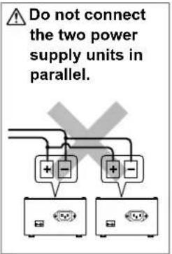
- Do not connect any non-specific power source to the +, - terminals. Also, do not install two power supplies in parallel to a single input. Fire or damage to the unit could result.
- Do not connect any terminal on the unit to an AC power line. Fire or electric shock could result.
- Keep AC cord from being marred or crushed. If the AC cord is damaged, fire or electric shock could result.
- Do not plug or unplug unit with wet hands. Electric shock could result.
- Insert AC plug completely and securely into AC outlet. Otherwise, fire or electric shock could result.
- Periodically check for and remove dust on the power plug. If dust is left, it could cause the power plug to heat up, resulting in fi re.
- Do not put any metal or fl ammable material into the unit through the openings. Fire, electric shock, or unit trouble could result.
CAUTION
Negligence could result in injury to people or damage to property.
- Do not install or make any wire terminations while power supply is plugged in. It can cause electrical shock or damage to the unit.
- When mounting the unit on a wall, install the unit in a convenient location, but not where it could be jarred or bumped. Injury could result.
- Before turning on power, make sure wires are not crossed or shorted. If not, fire or electric shock could result.
- Do not place or install the unit in the locations subject to frequent vibration or impact. If the unit falls, injury to people or damage to the unit could result.
-
Do not put anything on the unit or cover the unit with cloth, etc. Fire or unit trouble could result.
-
Do not install the unit in any of the following locations. Fire, electric shock, or unit trouble could result.
Places under direct sunlight or near heating equipment that * varies in temperature.
* Places subject to dust, oil, chemicals, hydrogen sulfide (hot spring).
Places subject to moisture and humidity extremes, such as * bathrooms, cellars, greenhouses, etc.
Places where the temperature is quite low, such as inside a * refrigerated area or in front of an air conditioner.
Places subject to steam or smoke (near heating or cooking * surfaces).
Where noise generating devices such as dimmer switches or * inverter electrical appliances are closeby.
Locations subject to frequent vibration or impact.*
* Locations subject to extremely powerful electric fields. -
Be sure to perform a call test or check the chime volume with the handset on the hook. If you operate the hook switch with the handset on your ear, a sudden call etc. may cause damage to your ear.
-
The unit must be installed and wired by a qualified technician.
GENERAL PRECAUTIONS
- Keep the unit more than 1 m (3.3') away from radio or TV sets.
- Keep the intercom wires more than 30cm (12") away from AC 100-240V wiring. AC induced noise and/or unit malfunction could result.
- Comply with all third party manufacturing specifications that will be used with this system.
- If it is used close to a cellular phone, the unit may malfunction.
- The unit can be damaged if dropped. Handle with care.
- The unit will not work during power failure.
- In areas where broadcasting station antennas are close by, the intercom system may be affected by radio frequency interference.
- All the units, except for Sub station, flush mount (NI-JA), are designed for indoor use only. Do not use at outdoor locations.
- Environmental sound around the unit may hinder clear communication, but this is not a malfunction.
- Using a mobile phone or professional-use radio equipment such as walkie-talkie close to the system may cause a malfunction.
NOTICES
- We will under no conditions be liable for damage that occurs due to the inability to communicate due to malfunctions, problems, or operational errors in this product.
- We will under no conditions be liable for any damages or losses resulting from this product's contents or specifications.
- This manual was created by Aiphone Co., Ltd., all rights reserved. Copying a part of or this entire manual without prior permission from Aiphone Co., Ltd. is strictly forbidden.
- Please note that images and illustrations depicted in this manual may differ from the actual ones.
- Please note that product specifications may be changed for the sake of improvement without prior notice.
- This system is not intended for life support or crime prevention. It is just a supplementary means of conveying information. Aiphone will under no conditions be liable for loss of life or property which occurs while the system is being operated.
System requirements for PC
Your PC must meet the following system requirements to use the NI-SOFT.
Also refer to the instruction manual supplied with your PC.
| OS(English ver. only) | Windows 7 Home Premium/Professional/Ultimate (Service Pack 1, 32/64bit) Windows 8.1/Pro (32/64bit) |
| Processor 2.7 GHz or higher | |
| System memory(RAM) | 2 GB RAM or higher |
| Hard disk Total 100 | MB or higher (*1) |
| Run-time Microsoft® | .NET Framework 4.5 (*2) |
| Display 1024 (W) x 7 | 68 (H) or higher, 16-bit or more |
| Serial port RS-232C | D-sub 9-pin |
| Fonts Arial | |
(*1): If the software is to be installed onto a drive other than C: drive, both the C: drive and the installation drive each require 50 MB or more of memory.
(*2): If the specified Run-time is not installed on the PC, it will be installed automatically when installing the NI-SOFT.

- The NI-SOFT may not run, or may not operate correctly (such as freezes occurring) on a PC with specifications below the necessary requirements.
- We recommend using a PC and CD-ROM/DVD-ROM drive that exceed the basic system requirements.
• The PC should be operable 24 hours a day. - Refer to the NI-SOFT operation manual included in the CD-ROM of the NI-SOFT for the setting method of the NI-SOFT.
Microsoft and Windows are either registered trademarks or trademarks of Microsoft Corporation in the United States and/or other countries.
System configuration
The following is a system configuration example. You can select needed equipment to configure a system to meet your application needs.
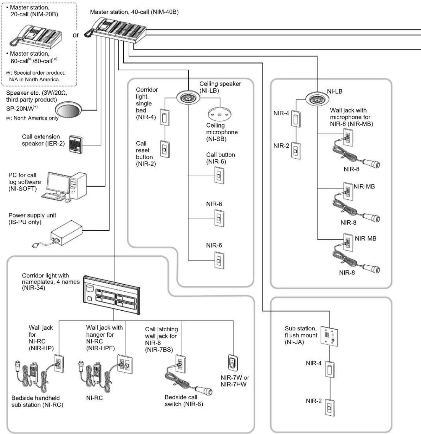
flowchart
graph TD
    A["Master station, 40-call (NIM-40B)"] --> B["Corridor light, single bed (NIR-4)"]
    A --> C["Ceiling speaker (NI-LB)"]
    A --> D["Ni-LB"]
    B --> E["Call reset button (NIR-2)"]
    C --> F["Ceiling microphone (NI-SB)"]
    C --> G["Call button (NIR-6)"]
    D --> H["NIR-4"]
    D --> I["NIR-2"]
    D --> J["NIR-8"]
    D --> K["NIR-8"]
    D --> L["NIR-8"]
    D --> M["NIR-8"]
    D --> N["NIR-8"]
    D --> O["NIR-8"]
    D --> P["NIR-8"]
    D --> Q["NIR-8"]
    D --> R["NIR-8"]
    D --> S["NIR-8"]
    D --> T["NIR-8"]
    D --> U["NIR-8"]
    D --> V["NIR-8"]
    D --> W["NIR-8"]
    D --> X["NIR-8"]
    D --> Y["NIR-8"]
    D --> Z["NIR-8"]
    D --> AA["NIR-8"]
    D --> AB["NIR-8"]
    D --> AC["NIR-8"]
    D --> AD["NIR-8"]
    D --> AE["NIR-8"]
    D --> AF["NIR-8"]
    D --> AG["NIR-8"]
    D --> AH["NIR-8"]
    D --> AI["NIR-8"]
    D --> AJ["NIR-8"]
    D --> AK["NIR-8"]
    D --> AL["NIR-8"]
    D --> AM["NIR-8"]
    D --> AN["NIR-8"]
    D --> AO["NIR-8"]
    D --> AP["NIR-8"]
    D --> AQ["NIR-8"]
    D --> AR["NIR-8"]
    D --> AS["NIR-8"]
    D --> AT["NIR-8"]
    D --> AU["NIR-8"]
    D --> AV["NIR-8"]
    D --> AW["NIR-8"]
    D --> AX["NIR-8"]
    D --> AY["NIR-8"]
    D --> AZ["NIR-8"]
    D --> BA["NIR-8"]
    D --> BB["NIR-8"]
    D --> BC["NIR-8"]
    D --> BD["NIR-8"]
    D --> BE["NIR-8"]
    D --> BF["NIR-8"]
    D --> BG["NIR-8"]
    D --> BH["NIR-8"]
    D --> BI["NIR-8"]
    D --> BJ["NIR-8"]
    D --> BK["NIR-8"]
    D --> BL["NIR-8"]
    D --> BM["NIR-8"]
    D --> BN["NIR-8"]
    D --> BO["NIR-8"]
    D --> BP["NIR-8"]
    D --> BQ["NIR-8"]
    D --> BR["NIR-8"]
    D --> BS["NIR-8"]
    D --> BT["NIR-8"]
    D --> BU["NIR-8"]
    D --> BV["NIR-8"]
    D --> BW["NIR-8"]
    D --> BX["NIR-8"]
    D --> BY["NIR-8"]
    D --> BZ["NIR-8"]
    D --> CA["NIR-8"]
    D --> CB["NIR-8"]
    D --> CC["NIR-8"]
    D --> CD["NIR-8"]
    D --> CE["NIR-8"]
    D --> CF["NIR-8"]
    D --> CG["NIR-8"]
    D --> CH["NIR-8"]
    D --> CI["NIR-8"]
    D --> CJ["NIR-8"]
    D --> CK["NIR-8"]
NOTE: The above example may differ from actual product.
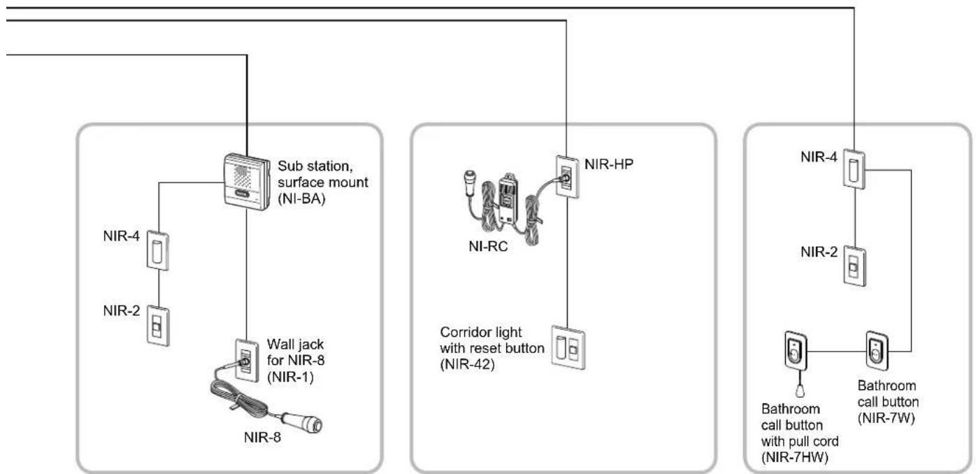
flowchart
graph TD
    A["NIR-2"] --> B["Sub station, surface mount (NI-BA)"]
    C["NIR-4"] --> B
    D["NIR-8"] --> E["Wall jack for NIR-8 (NIR-1)"]
    F["NIR-8"] --> G["Corridor light with reset button (NIR-42)"]
    H["NIR-HP"] --> I["NIR-4"]
    J["Bathroom call button with pull cord (NIR-7HW)"] --> K["Bathroom call button (NIR-7W)"]
■ Maximum number of stations in a single system
The maximum number of sub stations differs depending on the master station model.
| Master station | Sub station (Qty) Personal computer (Qty) | ||
| Model Qty | |||
| NIM-20B 1 | 2 | 0 | 1 |
| NIM-40B 1 | 4 | 0 | 1 |
| Master station, 60-call (*) | 1 | 6 | 0 |
| Master station, 80-call (*) | 1 | 8 | 0 |
1
1
(*): Special order product.
N/A in North America.
■ Communication methods
The following two methods are available on the master station.
| Method Communication style Description | ||
| Using handset | Voice-actuated communication | The communication mode is VOX, half duplex. When speaking into the handset, voice is transmitted to the other station. When listening, the voice from the remote station is heard through the handset. |
| Hands-free Push-to-talk | To speak, press and hold the TALK button.To listen, release the TALK button. | |
Package contents and dimensions
Verify that the following parts are included for each product package.
* Dimensions are shown in millimeters (inches).
Master station
■ Master station, 20-call (NIM-20B)
■ Master station, 40-call (NIM-40B)
* Master station, 60-call(*) or Master station, 80-call(*) is also available.
(*): Special order product. N/A in North America.
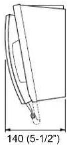
Main unit
NIM-20B (Front)

NIM-40B (Front)

(Side)
Room number plate Nameplate


NIM-20B: 22pcs.
NIM-40B: 44pcs.
Master station, 60-call: 66pcs.
Master station, 80-call: 88pcs.

Chinese RoHS paper

Sub station, call button, wall jack
■ Bedside handheld sub station (NI-RC)

other
| Component | Dimension | | ----------------- | --------------- | | Main unit Hanging | (Front) | | Main unit Hanging | (Side) | | Main unit Hanging | (Side) | | Chinese RoHS paper | (Front) | | Chinese RoHS paper | (Side) |■ Wall jack for NI-RC (NIR-HP)

■ Wall jack with hanger for NI-RC (NIR-HPF)
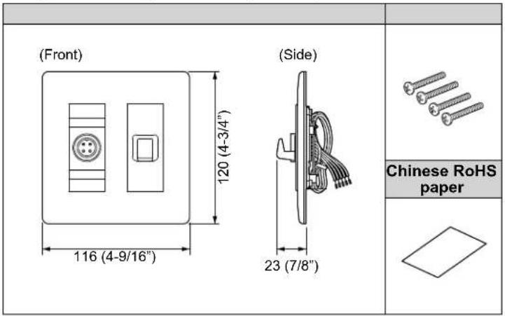
■ Sub station, fl ush mount (NI-JA)

■ Sub station, surface mount (NI-BA)
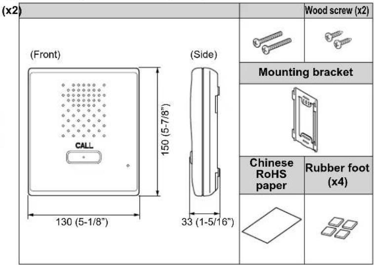
■ Bedside call switch (NIR-8)

■ Wall jack for NIR-8 (NIR-1)

■ Wall jack with microphone for NIR-8 (NIR-MB)

■ Call latching wall jack for NIR-8 (NIR-7BS)

■ Call button (NIR-6)

■ Bathroom call button with pull cord (NIR-7HW)
■ Bathroom call button (NIR-7W)


Ceiling speaker, ceiling microphone
■ Ceiling speaker (NI-LB)
| Main unit | Chinese RoHS paper |
| (Side) (Front) ø180 (7-1/16") | |
| Holder | |
| (Side) 65 (2-9/16") | |
■ Ceiling microphone (NI-SB)

Corridor light, reset button
■ Corridor light, single bed (NIR-4)
■ Corridor light, multiple beds (NIR-4S)

■ Call reset button (NIR-2)
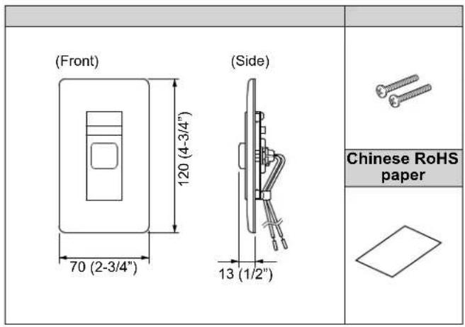
■ Corridor light with reset button (NIR-42)
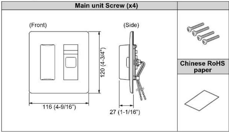
■ Corridor light with buzzer (NIR-4BZ)

■ Corridor light with nameplate, 1 name (NIR-31)
| Main unit Mounting bracket | Room number plate | Nameplate | |
 |  |  | |
| Screw (x4) Chinese RoHS paper | |||
 | |||
■ Corridor light with nameplates, 2 names (NIR-32)
| Main unit Mounting bracket | Room number plate | Nameplate (x2) | ||
(Front)  | (Side)  |  |  |  |
| Screw (x4) Chinese RoHS paper | ||||
 |  | |||
■ Corridor light with nameplates, 4 names (NIR-34)
| Main unit Mounting bracket | Room number plate | Nameplate (x4) | |
(Front)  (Side) (Side)  |  |  |  |
| Screw (x4) Chinese | RoHS paper | ||
 |  | ||
Software
■ Call log software (NI-SOFT)
| CD-ROM RS232C | cable | Product Key code paper/ Chinese RoHS paper |
 |  |  |
This section illustrates the mounting procedures for wall- and ceiling-mount equipment.
■ Ceiling speaker (NI-LB)

■ Ceiling microphone (NI-SB)

NOTE:
- Make sure to mount the ceiling microphone 50 cm (20") apart from the ceiling speaker to prevent audio feedback.
- Pay attention to the depth of the unit.
- Use board anchors or concrete plugs as needed on a concrete wall.
■ Wall jack (NIR-HP, NIR-1, NIR-MB, NIR-7BS)
Call button (NIR-6)
Corridor light (NIR-4, NIR-4S)
Call reset button (NIR-2)
* The illustration shows the wall jack for NI-RC (NIR-HP).
Bathroom call button (NIR-7W, NIR-7HW)
* The illustration shows the bathroom call button (NIR-7W).

■ Sub station, surface mount (NI-BA)
* When mounting NI-BA on a wall, follow the procedure shown below.

When setting NI-BA on a desk
- Attach the included 4 rubber feet on the back of NI-BA.
- Route the wires through the cable inlet at the upper or lower part of NI-BA.
When routing the wires at the upper part, remove the cable inlet plate to allow passage of the wires.

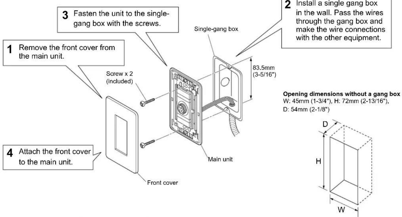
■ Sub station, fl ush mount (NI-JA)

1 Install a 2 gang box in the wall. Pass the wires through the gang box and make the wire connections with the terminal cover open.
* Be sure to route the wires through inlet.
Opening dimensions without a gang box
W: 90mm (3-9/16"), H: 73mm (2-7/8"), D: 54mm (2-1/8")
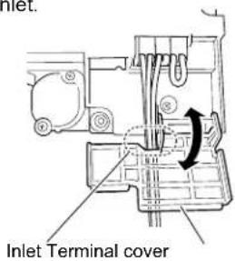
■ Wall jack (NIR-HPF)
Corridor light (NIR-42, NIR-4BZ)
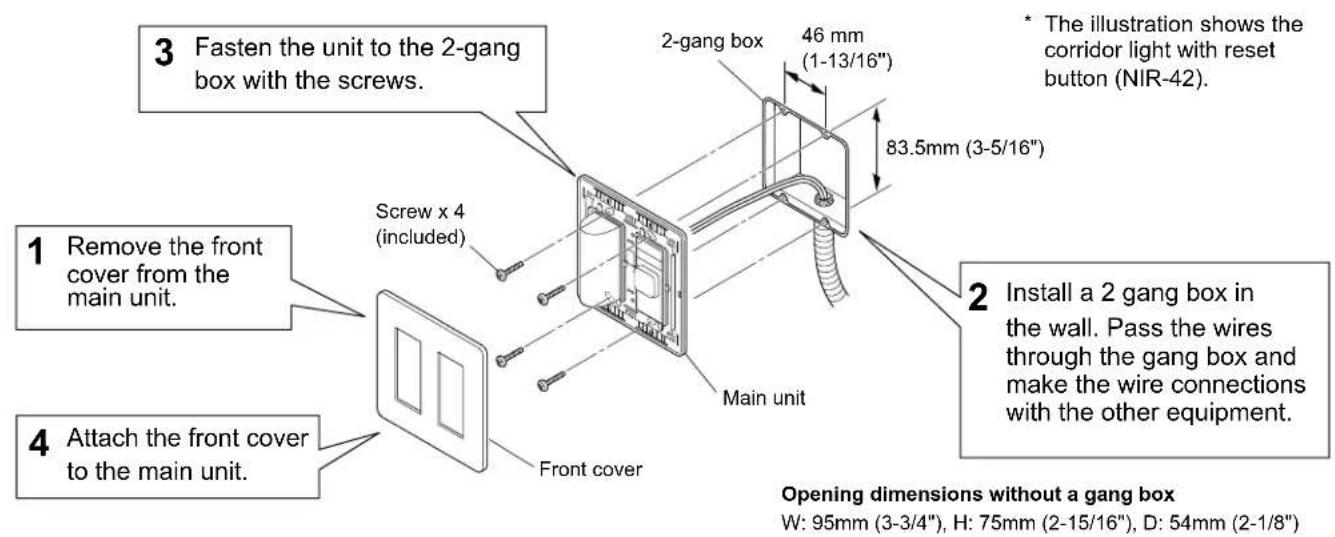
■ Corridor light with nameplate (NIR-31, NIR-32, NIR-34)
* The illustration shows the corridor light with nameplates, 4 names (NIR-34).

Connection wiring diagram (outline)
The following is an example of basic wiring diagram.
* The wiring methods differ depending on the equipment used. Refer to page 20 to 29 for details about various wiring methods.

flowchart
graph TD
    A["Master station, 40-call (NIM-40B)"] -->|or| B["Master station, 20-call (NIM-20B)"]
    B --> C["Master station, 60-call*"]
    C --> D["Master station, 80-call*"]
    D --> E["Special order product. N/A in North America."]
    F["Call extension speaker (IER-2)"] --> G["Speaker etc. (3W/20Ω, third party product)"]
    G --> H["SP-20N/A(*): North America only"]
    H --> I["RS232C cable (included on Ni-SOFT)"]
    I --> J["Power supply unit (IS-PU only)"]
    J --> K["When using the master station, 60-call or 80-call, two power supplies are needed."]
    L["PC"] --> M["TX RX I-G"]
    M --> N["+ -"]
    O["Power supply unit (IS-PU only)"] --> P["E M"]
    P --> Q["31 32 33 34 ... 39 40"]
    R["Call extension speaker (IER-2)"] --> S["S1 S1 SK SK"]
    S --> T["S1 S1 SK SK"]
    U["Power supply unit (IS-PU only)"] --> V["E M"]
    V --> W["31 32 33 34 ... 39 40"]

    X["Ceiling speaker (NI-LB)"] --> Y["Red Yellow Black White Gray"]
    Y --> Z["Blue Corridor light, single bed (NIR-4)"]
    Y --> AA["Blue Call reset button (NIR-2)"]

    AB["Wall jack for NIR-8 (NIR-1)"] --> AC["Blue Bedside call switch (NIR-8)"]
    AC --> AD["Gray White Ceiling microphone (NI-SB)"]

    AE["Wall jack with microphone for NIR-8 (NIR-MB)"] --> AF["Blue White Gray Blue Blue White"]

    AG["Power supply unit (IS-PU only)"] --> AH["White Red Black White"]

    AI["Call extension speaker (IER-2)"] --> AJ["S1 S1 SK SK"]

    AK["Call extension speaker (IER-2)"] --> AL["S1 S1 SK SK"]

    AM["Power supply unit (IS-PU only)"] --> AN["E M"]

    AO["Call extension speaker (IER-2)"] --> AP["S1 S1 SK SK"]

    AQ["Call extension speaker (IER-2)"] --> AR["S1 S1 SK SK"]

    AS["Power supply unit (IS-PU only)"] --> AT["E M"]

    AU["Call extension speaker (IER-2)"] --> AV["S1 S1 SK SK"]

    AW["Call extension speaker (IER-2)"] --> AX["S1 S1 SK SK"]

    AY["Call extension speaker (IER-2)"] --> AZ["S1 S1 SK SK"]

    BA["Call extension speaker (IER-2)"] --> BB["S1 S1 SK SK"]

    BC["Call extension speaker (IER-2)"] --> BD["S1 S1 SK SK"]

    BE["Call extension speaker (IER-2)"] --> BF["S1 S1 SK SK"]

    BG["Call extension speaker (IER-2)"] --> BH["S1 S1 SK SK"]

    BI["Call extension speaker (IER-2)"] --> BJ["S1 S1 SK SK"]

    BK["Call extension speaker (IER-2)"] --> BL["S1 S1 SK SK"]

    BM["Call extension speaker (IER-2)"] --> BN["S1 S1 SK SK"]

    BO["Call extension speaker (IER-2)"] --> BP["S1 S1 SK SK"]

    BQ["Call extension speaker (IER-2)"] --> BR["S1 S1 SK SK"]

    BS["Call extension speaker (IER-2)"] --> BT["S1 S1 SK SK"]

    BU["Call extension speaker (IER-2)"] --> BV["S1 S1 SK SK"]

    BW["Call extension speaker (IER-2)"] --> BX["S1 S1 SK SK"]

    BY["Call extension speaker (IER-2)"] --> BZ["S1 S1 SK SK"]

    CA["Call extension speaker (IER-2)"] --> CB["S1 S1 SK SK"]

    CC["Call extension speaker (IER-2)"] --> CD["S1 S1 SK SK"]

    CE["Call extension speaker (IER-2)"] --> CF["S1 S1 SK SK"]

    DG["Call extension speaker (IER-2)"] --> DH["S1 S1 SK SK"]

    DI["Call extension speaker (IER-2)"] --> DJ["S1 S1 SK SK"]

    DK["Call extension speaker (IER-2)"] --> DL["S1 S1 SK SK"]

    EM["Call extension speaker (IER-2)"] --> EM
    EN["Call extension speaker (IER-2)"] --> EN
    AO["Call extension speaker (IER-2)"] --> AO
    AP["Call extension speaker (IER-2)"] --> AQ
    AR["Call extension speaker (IER-2)"] --> AR
    AS["Call extension speaker (IER-2)"] --> AT
    AU["Call extension speaker (IER-2)"] --> AU
    AV["Call extension speaker (IER-2)"] --> AW
    AX["Call extension speaker (IER-2)"] --> AX
    AY["Call extension speaker (IER-2)"] --> AZ["S1 S1 SK SK"]

    BA --> BA
    BB --> BB
    BC --> BB
    AD --> BB
    AE --> BB
    AF --> BB
    AG --> BB
    AH --> BB
    AI --> BB
    AJ --> BB
    AK --> BB
    AL --> BB
    AM --> BB
    AN --> BB
    AO --> BB
    AP --> BB
    AQ --> BB
    AR --> BB
    AS --> BB
    AT --> BB
    AU --> BB
    AV --> BB
    AW --> BB
    AX --> BB
    AO --> BB
    AP --> BB
    AQ --> BB
    AS --> BB
    AT --> BB
    AU --> BB
    AV --> BB
    AW --> BB
    AX --> BB
    AO --> BB
    AP --> BB
    AQ --> BB
    AS --> BB
    AT --> BB
    AU --> BB
    AV --> BB

    BI["Call extension speaker (IER-2)"] --> BJ["S1 S1 SK SK"]

    BK["Call extension speaker (IER-2)"] --> BL["S1 S1 SK SK"]

    BL --> BK
    BM --> BK
    AN --> BK
    AO --> BK
    AP --> BK
    AQ --> BK
    AS --> BK
    AT --> BK
</details>
(\*1): • The common line E and individual channel lines should be in the same sheath wiring.
• The remainder wires in the same sheath wiring should be connected to the common line E of the master station for noise prevention.

<details>
<summary>flowchart</summary>
```mermaid
graph TD
A["Sub station, fl ush mount (NI-JA)"] --> B["A"]
A --> C["M"]
A --> D["E"]
A --> E["C"]
A --> F["CE"]
A --> G["CS"]
B --> H["NIR-4"]
C --> I["NIR-2"]
D --> J["NIR-2"]
E --> K["NIR-2"]
F --> L["NIR-2"]
H --> M["Blue"]
I --> N["Blue"]
K --> O["Blue"]
M --> P["A"]
N --> Q["I"]
O --> R["CE"]
P --> S["NIR-1"]
Q --> T["NIR-1"]
R --> U["NIR-1"]
S --> V["NIR-8"]
T --> W["NIR-8"]
U --> X["NIR-8"]
style A fill:#f9f,stroke:#333
style B fill:#ccf,stroke:#333
style C fill:#ccf,stroke:#333
style D fill:#ccf,stroke:#333
style E fill:#ccf,stroke:#333
style F fill:#ccf,stroke:#333
style G fill:#ccf,stroke:#333
style H fill:#cfc,stroke:#333
style I fill:#cfc,stroke:#333
style J fill:#cfc,stroke:#333
style K fill:#cfc,stroke:#333
style L fill:#cfc,stroke:#333
style M fill:#fcc,stroke:#333
style N fill:#fcc,stroke:#333
style O fill:#fcc,stroke:#333
style P fill:#cff,stroke:#333
style Q fill:#cff,stroke:#333
style R fill:#cff,stroke:#333
style S fill:#cff,stroke:#333
style T fill:#cff,stroke:#333
style U fill:#cff,stroke:#333
style V fill:#cff,stroke:#333
style W fill:#cff,stroke:#333
■ Wiring distance
| Wire diameter Maximum distance | ||
| Master station - sub station | 0.65mm (22 AWG) 0.9mm (18 AWG) | 130m (425')200m (650') |
| Master station - power supply unit | 0.9mm (18 AWG) 10m (33') | |
| Master station - call extension speaker (IER-2), speaker etc. | 0.9mm (18 AWG) 50m (165') | |
■ Master station terminal marking
E : Common line (for earth ground)
M : Common line (for microphone)
1…10, 11…: Individual channel line
■ Meanings of symbols
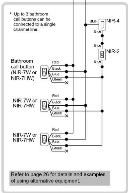
●: Wire-to-wire connection
✗: The wire should be cut and insulated.

Handling cables
Notes about handling cables
* Cables and connectors are not included with the products.
Notes on cables
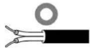
- Use PE (polyethylene)-insulated PVC jacketed cable.
Parallel or jacketed conductors, mid-capacitance, non-shielded cable is recommended. - Never use twisted pair cable or coaxial cable.

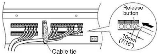
■ How to connect or disconnect stranded wires.
- To ensure that the wire won't bend, press the release button while inserting into terminal.
e.g.) NIM-40B

e.g.) NI-BA

■ Note about wire-to-wire connection.
Make wire-to-wire connections securely as shown below.

Connection wiring diagram (details)
Connecting to the master station
Procedure
1 Detach the terminal cover by removing the two screws.

2 Connect the wiring from the sub stations and power supply to the master station by inserting lead wires to the corresponding terminals.
Using the cable tie is recommended for secure installation.
3 After the connections for the whole system have been completed, turn on the power switch.

The power indicator on the operation panel lights up.

4 Attach the terminal cover with the two screws.
■ Note about connecting a PC to the master station.
Use the included RS232C cable for the connection.
* Install NI-SOFT on the PC from the included CD-ROM. Refer to the instruction manual for NI-SOFT for details.

* When extending the RS232C cable, the distance between the master station and the PC should be 15m (50') or less.

CAUTION
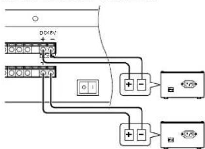
■ Note about connecting the power supply unit(s) to the master station.
* When using the master station, 60-call or 80-call, two power supply units are needed.
NIM-20B/NIM-40B

Master station, 60-call/80-call
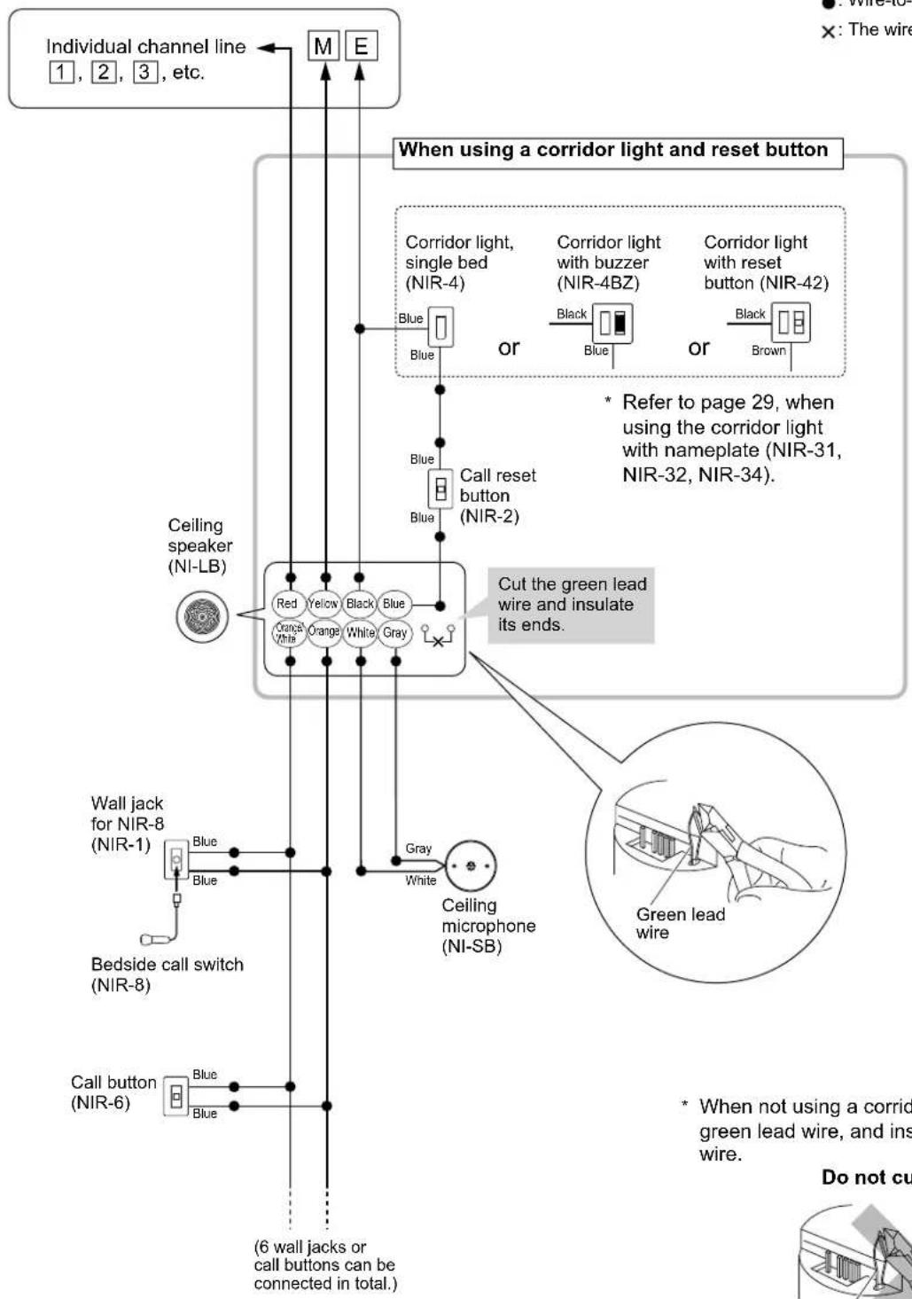
Multiple-user room examples of using the ceiling speaker (NI-LB) and the ceiling microphone (NI-SB)
Master station
flowchart
graph TD
    A["Individual channel line 1, 2, 3, etc."] --> B["M"]
    A --> C["E"]
    B --> D["When using a corridor light and reset button"]
    C --> D
    D --> E["Corridor light, single bed (NIR-4)"]
    D --> F["Corridor light with buzzer (NIR-4BZ)"]
    D --> G["Corridor light with reset button (NIR-42)"]
    E --> H["Blue"]
    F --> I["Black"]
    G --> J["Black"]
    H --> K["Call reset button (NIR-2)"]
    I --> K
    J --> K
    K --> L["Ceiling speaker (NI-LB)"]
    L --> M["Red"]
    L --> N["Yellow"]
    L --> O["Black"]
    L --> P["Blue"]
    L --> Q["Orange White"]
    L --> R["Orange"]
    L --> S["White"]
    L --> T["Gray"]
    M --> U["Cut the green lead wire and insulate its ends."]
    N --> U
    O --> U
    P --> U
    Q --> U
    R --> U
    S --> U
    T --> U
    U --> V["Ceiling microphone (NI-SB)"]
    V --> W["Blue"]
    V --> X["White"]
    W --> Y["Green lead wire"]
    X --> Y
    Y --> Z["Call button (NIR-6)"]
    Z --> AA["Blue"]
    Z --> AB["Blue"]
    AA --> AC["(6 wall jacks or call buttons can be connected in total.)"]
■ Meanings of symbols
●: Wire-to-wire connection
✗: The wire should be cut and insulated.
to page 29, when the corridor light nameplate (NIR-31, 2, NIR-34).

natural_image
Simple line drawing of a hand holding a small object, enclosed in a circle (no text or symbols)* When not using a corridor light, do not cut the green lead wire, and insulate the blue lead wire.
Do not cut.

natural_image
Illustration of a hand using a tool to adjust or install a component, no text or symbols visibleGreen lead wire
Multiple-user room examples of using the ceiling speaker (NI-LB) and not using the ceiling microphone (NI-SB)
Master station

flowchart
graph TD
    A["Individual channel line 1, 2, 3, etc."] --> B["M"]
    A --> C["E"]
    B --> D["When using a corridor light and reset button"]
    C --> D
    D --> E["Corridor light, single bed (NIR-4)"]
    D --> F["Corridor light with buzzer (NIR-4BZ)"]
    D --> G["Corridor light with reset button (NIR-42)"]
    E --> H["Blue"]
    F --> I["Black"]
    G --> J["Blue"]
    H --> K["Call reset button (NIR-2)"]
    I --> K
    J --> K
    K --> L["Ceiling speaker (NI-LB)"]
    L --> M["Red"]
    L --> N["Yellow"]
    L --> O["Black"]
    L --> P["Blue"]
    L --> Q["Orange White"]
    L --> R["Orange"]
    L --> S["White"]
    L --> T["Gray"]
    M --> U["Cut the green lead wire and insulate its ends."]
    N --> U
    O --> U
    P --> U
    Q --> U
    R --> U
    S --> U
    T --> U
    U --> V["Green lead wire"]
    V --> W["Bedside call switch (NIR-8)"]
    W --> X["Wall jack with microphone for NIR-8 (NIR-MB)"]
    X --> Y["Blue"]
    X --> Z["Blue"]
    X --> AA["White"]
    X --> AB["Gray"]
    Y --> AC["(6 wall jacks with microphone can be connected in total.)"]
    Z --> AC
    AA --> AC
    AB --> AC
■ Meanings of symbols
●: Wire-to-wire connection
✗: The wire should be cut and insulated.
●: Wire-to-wire connection
✗: The wire should be cut and insulated.
* When not using a corridor light, do not cut the green lead wire, and insulate the blue lead wire.
Do not cut.

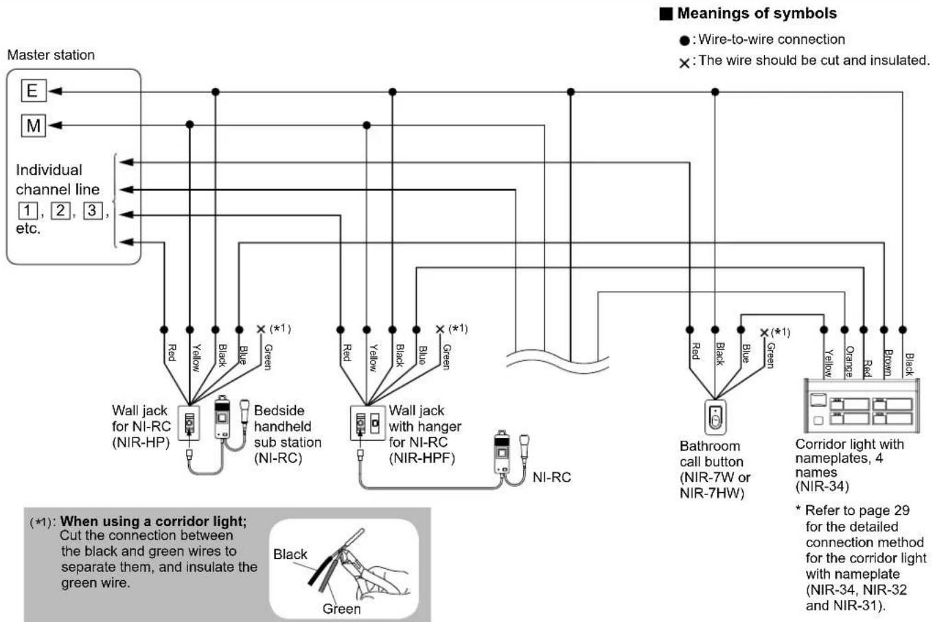
Multiple-user room examples of using the bedside handheld sub stations (NI-RC) etc.
flowchart
graph TD
    A["Master station"] --> B["Wall jack for NI-RC (NIR-HP)"]
    A --> C["Bedside handheld sub station (NI-RC)"]
    A --> D["Bathroom call button (NIR-7W or NIR-7HW)"]
    B --> E["Red"]
    B --> F["Yellow"]
    B --> G["Black"]
    B --> H["Blue"]
    B --> I["Green (*1)"]
    C --> J["Red"]
    C --> K["Yellow"]
    C --> L["Black"]
    C --> M["Blue"]
    C --> N["Green (*1)"]
    D --> O["Red"]
    D --> P["Yellow"]
    D --> Q["Black"]
    D --> R["Blue"]
    D --> S["Green (*1)"]
    T["Bathroom call button (NIR-7W or NIR-7HW)"] --> U["Bathroom call button (NIR-7W or NIR-7HW)"]
    U --> V["Bathroom call button (NIR-7W or NIR-7HW)"]
    V --> W["Bathroom call button (NIR-7W or NIR-7HW)"]
    X["Corridor light with nameplates, 4 names (NIR-34)"] --> Y["Yellow"]
    X --> Z["Orange"]
    X --> AA["Red"]
    X --> AB["Brown"]
    X --> AC["Black"]
    style A fill:#f9f,stroke:#333
    style B fill:#ccf,stroke:#333
    style C fill:#ccf,stroke:#333
    style D fill:#ccf,stroke:#333
    style E fill:#fff,stroke:#333
    style F fill:#fff,stroke:#333
    style G fill:#fff,stroke:#333
    style H fill:#fff,stroke:#333
    style I fill:#fff,stroke:#333
    style J fill:#fff,stroke:#333
    style K fill:#fff,stroke:#333
    style L fill:#fff,stroke:#333
    style M fill:#fff,stroke:#333
    style N fill:#fff,stroke:#333
    style O fill:#fff,stroke:#333
    style P fill:#fff,stroke:#333
    style Q fill:#fff,stroke:#333
    style R fill:#fff,stroke:#333
    style S fill:#fff,stroke:#333
    style T fill:#fff,stroke:#333
    style U fill:#fff,stroke:#333
    style V fill:#fff,stroke:#333
    style W fill:#fff,stroke:#333
    style X fill:#fff,stroke:#333
    style Y fill:#fff,stroke:#333
    style Z fill:#fff,stroke:#333
    style AA fill:#fff,stroke:#333
    style AB fill:#fff,stroke:#333
    style AC fill:#fff,stroke:#333
When using the corridor light, multiple beds (NIR-4S) and call reset button (NIR-2)

flowchart
graph TD
    A["Master station"] --> B["E"]
    A --> C["M"]
    B --> D["NIR-HP"]
    C --> E["NIR-HPF"]
    D --> F["NI-RC"]
    E --> G["NI-RC"]
    F --> H["NIR-HP"]
    G --> I["NIR-HPF"]
    H --> J["NIR-7W or NIR-7HW"]
    I --> J
    style A fill:#f9f,stroke:#333
    style B fill:#ccf,stroke:#333
    style C fill:#ccf,stroke:#333
    style D fill:#cfc,stroke:#333
    style E fill:#cfc,stroke:#333
    style F fill:#cfc,stroke:#333
    style G fill:#cfc,stroke:#333
    style H fill:#fcc,stroke:#333
    style I fill:#fcc,stroke:#333
    style J fill:#cff,stroke:#333
(*1): When using a corridor light; Cut the connection between the black and green wires to separate them, and insulate the green wire.

When using equipment without microphone (no communication is possible)
Master station

flowchart
graph TD
    A["Call latching wall jack for NIR-8"] --> B["Red"]
    A --> C["Orange"]
    A --> D["Black"]
    A --> E["Blue"]
    A --> F["X (★1)"]
    A --> G["Green"]
    H["Individual channel line 1, 2, 3, etc."] --> I["●"]
    I --> J["●"]
    I --> K["●"]
    I --> L["●"]
    I --> M["●"]
    I --> N["●"]
    I --> O["●"]
    P["E"] --> Q["●"]
    Q --> R["●"]
    R --> S["●"]
    S --> T["●"]
    T --> U["●"]
    U --> V["●"]
    V --> W["●"]
    W --> X["●"]
    X --> Y["●"]
    Y --> Z["●"]
    Z --> AA["●"]
    AA --> AB["●"]
    AB --> AC["●"]
    AC --> AD["●"]
    AD --> AE["●"]
    AE --> AF["●"]
    AF --> AG["●"]
    AG --> AH["●"]
    AH --> AI["●"]
    AI --> AJ["●"]
    AJ --> AK["●"]
    AK --> AL["●"]
    AL --> AM["●"]
    AM --> AN["●"]
    AN --> AO["●"]
    AO --> AP["●"]
    AP --> AQ["●"]
    AQ --> AR["●"]
    AR --> AS["●"]
    AS --> AT["●"]
    AT --> AU["●"]
    AU --> AV["●"]
    AV --> AW["●"]
    AW --> AX["●"]
    AX --> AY["●"]
(*1): When using a corridor light; Cut the connection between the black and green wires to separate them, and insulate the green and orange lead wire.

(*2): The orange lead wire should be insulated.
Corridor light with nameplates, 4 names (NIR-34)
* Refer to page 29 for the detailed connection method for the corridor light with nameplate (NIR-34, NIR-32 and NIR-31).
When not using a corridor light
Master station

flowchart
graph TD
    A["NIR-HP"] -->|Red| B["NI-RC"]
    B -->|Yellow| C["Red"]
    B -->|Black| D["Yellow"]
    B -->|Blue| E["Green"]
    F["NIR-7W or NIR-7HW"] -->|Red| G["Red"]
    F -->|Black| H["Green"]
    F -->|Blue| I["Green"]
    J["E"] --> A
    K["M"] --> A
    L["Individual channel line 1, 2, 3, etc."] --> A
    M["(*3)"] --> B
    N["(*4)"] --> B
(*3): When not using a corridor light; Do not cut the connection between the black and green wires. Insulate the blue lead wire.

(*4): The blue lead wire should be insulated.
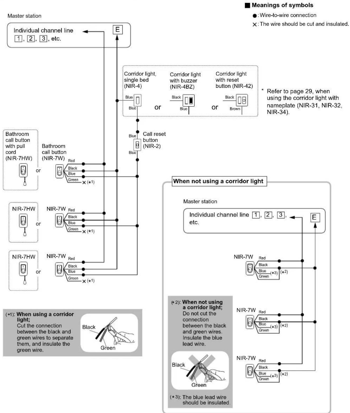
Examples of using the bathroom call buttons (NIR-7W or NIR-7HW)
When using a corridor light and reset button
flowchart
graph TD
    A["Master station"] --> B["Individual channel line 1, 2, 3, etc."]
    B --> C["E"]
    C --> D["Bathroom call button with pull cord (NIR-7HW)"]
    D --> E["Bathroom call button (NIR-7W)"]
    E --> F["Bathroom call button (NIR-7W) or Red Black Blue Green × (*1)"]
    F --> G["NIR-7W"]
    G --> H["NIR-7W or Red Black Blue Green × (*1)"]
    H --> I["NIR-7W or Red Black Blue Green × (*1)"]
    I --> J["When not using a corridor light"]
    J --> K["Master station"]
    K --> L["NIR-7W"]
    L --> M["NIR-7W or Red Black Blue Green × (*2)"]
    M --> N["NIR-7W or Red Black Blue Green × (*2)"]
    N --> O["NIR-7W or Red Black Blue Green × (*3)"]
    O --> P["When not using a corridor light; Do not cut the connection between the black and green wires. Insulate the blue lead wire."]
    P --> Q["Black Green"]
    Q --> R["Black Green"]
    R --> S["Black Green"]
    S --> T["Black Green"]
    T --> U["Black Green"]
    U --> V["Black Green"]
    V --> W["Black Green"]
    W --> X["Black Green"]
    X --> Y["Black Green"]
    Y --> Z["Black Green"]
    Z --> AA["Black Green"]
    AA --> AB["Black Green"]
    AB --> AC["Black Green"]
    AC --> AD["Black Green"]
    AD --> AE["Black Green"]
    AE --> AF["Black Green"]
    AF --> AG["Black Green"]
    AG --> AH["Black Green"]
    AH --> AI["Black Green"]
    AI --> AJ["Black Green"]
    AJ --> AK["Black Green"]
    AK --> AL["Black Green"]
    AL --> AM["Black Green"]
    AM --> AN["Black Green"]
    AN --> AO["Black Green"]
    AO --> AP["Black Green"]
    AP --> AQ["Black Green"]
    AQ --> AR["Black Green"]
    AR --> AS["Black Green"]
    AS --> AT["Black Green"]
    AT --> AU["Black Green"]
    AU --> AV["Black Green"]
    AV --> AW["Black Green"]
    AW --> AX["Black Green"]
    AX --> AY["Black Green"]
    AY --> AZ["Black Green"]
    AZ --> BA["Black Green"]
    BA --> BB["Black Green"]
    BB --> BC["Black Green"]
    BC --> BD["Black Green"]
    BD --> BE["Black Green"]
    BE --> BF["Black Green"]
    BF --> BG["Black Green"]
    BG --> BH["Black Green"]
    BH --> BI["Black Green"]
    BI --> BJ["Black Green"]
    BJ --> BK["Black Green"]
    BK --> BL["Black Green"]
    BL --> BM["Black Green"]
    BM --> BN["Black Green"]
    BN --> BO["Black Green"]
    BO --> BP["Black Green"]
    BP --> BQ["Black Green"]
    BQ --> BR["Black Green"]
    BR --> BS["Black Green"]
    BS --> BT["Black Green"]
    BT --> BU["Black Green"]
    BU --> BV["Black Green"]
    BV --> BW["Black Green"]
    BW --> BX["Black Green"]
    BX --> BY["Black Green"]
    BY --> BZ["Black Green"]
    BZ --> CA["Black Green"]
    CA --> CB["Black Green"]
    CB --> CC["Black Green"]
    CC --> CD["Black Green"]
    CD --> CE["Black Green"]
    CE --> CF["Black Green"]
    CF --> CG["Black Green"]
    CG --> CH["Black Green"]
    CH --> CI["Black Green"]
    CI --> CJ["Black Green"]
    CJ --> CK["Black Green"]
* Up to 3 bathroom call buttons can be connected to a single channel line.
Single room examples of using the surface mount sub station (NI-BA)
When using a corridor light and reset button

flowchart
graph TD
    A["Master station"] --> B["Individual channel line 1, 2, 3, etc."]
    B --> C["M E"]
    C --> D["Sub station, surface mount (NI-BA)"]
    D --> E["A M E C (*1)"]
    E --> F["Wall jack for NIR-8 (NIR-1)"]
    F --> G["Call button (NIR-6)"]
    G --> H["Bedside call switch (NIR-8)"]
    H --> I["Blue"]
    I --> J["Corridor light, single bed (NIR-4)"]
    I --> K["Corridor light with buzzer (NIR-4BZ)"]
    I --> L["Corridor light with reset button (NIR-42)"]
    I --> M["Call reset button (NIR-2)"]
    M --> N["Blue"]
    N --> O["When not using a corridor light"]
    O --> P["Sub station, surface mount (NI-BA)"]
    P --> Q["A M E C (*2)"]
    Q --> R["Do not remove the lead wire between the CE and CS terminals. The C terminal is not used."]
    style A fill:#f9f,stroke:#333
    style B fill:#ccf,stroke:#333
    style C fill:#cfc,stroke:#333
    style D fill:#fcc,stroke:#333
    style E fill:#cff,stroke:#333
    style F fill:#ffc,stroke:#333
    style G fill:#cfc,stroke:#333
    style H fill:#fcc,stroke:#333
    style I fill:#ffc,stroke:#333
    style J fill:#cfc,stroke:#333
    style K fill:#cfc,stroke:#333
    style L fill:#cfc,stroke:#333
    style M fill:#cfc,stroke:#333
    style N fill:#cfc,stroke:#333
    style O fill:#cfc,stroke:#333
    style P fill:#cfc,stroke:#333
    style Q fill:#cfc,stroke:#333
    style R fill:#cfc,stroke:#333
■ Meanings of symbols
●: Wire-to-wire connection
Examples of using the fl ush mount sub station (NI-JA)
When using a corridor light and reset button
■ Meanings of symbols
● : Wire-to-wire connection
Master station

flowchart
graph TD
    A["Individual channel line 1, 2, 3, etc."] --> B["M"]
    B --> C["E"]
    C --> D["Sub station, flush mount (NI-JA)"]
    D --> E["A"]
    D --> F["M"]
    D --> G["E"]
    D --> H["C"]
    D --> I["CE"]
    D --> J["CS"]
    E --> K["Call reset button (NIR-2)"]
    F --> K
    G --> K
    H --> K
    I --> K
    J --> K
    K --> L["Corridor light, single bed (NIR-4)"]
    K --> M["Corridor light with buzzer (NIR-4BZ)"]
    K --> N["Corridor light with reset button (NIR-42)"]
    L --> O["Blue"]
    M --> P["Black"]
    N --> Q["Brown"]
    O --> R["OR"]
    P --> R
    Q --> R
    R --> S["* Refer to page 29, when using the corridor light with nameplate (NIR-31, NIR-32, NIR-34)."]
    T["When not using a corridor light"] --> U["Sub station, flush mount (NI-JA)"]
    U --> V["A"]
    U --> W["M"]
    U --> X["E"]
    U --> Y["C"]
    U --> Z["CE"]
    U --> AA["CS"]
    V --> AB["*2"]
    W --> AB
    X --> AB
    Y --> AB
    Z --> AB
    AA --> AB
    AB --> AC["*2: Do not remove the lead wire between the CE and CS terminals. The C terminal is not used."]
Notes about connecting to a corridor light with nameplate (NIR-31, NIR-32, NIR-34)
The individual user displays and the corresponding lead wire colors are as follows.
When the call button of a sub station connected to one of the color-coded lead wires of the corridor light is pressed, the corresponding number of the call indicator lights.
NIR-31
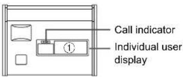
| Individual user display | Color of lead wire |
| 1 | Brown |
NIR-32

| Individual user display | Color of lead wire |
| 1 | Brown |
| 2 | Red |
NIR-34

| Individual user display | Color of lead wire |
| 1 | Brown |
| 2 | Red |
| 3 | Orange |
| 4 | Yellow |
e.g.
When the call button of the sub station connected to the red lead wire is pressed, the call indicator of display ② lights.

Wiring example
Master station

flowchart
graph TD
    A["Individual channel line"] --> B["Sub station ①"]
    A --> C["Sub station ②"]
    A --> D["Sub station ③"]
    A --> E["Bathroom call button ④"]
    A --> F["Corridor light with nameplates, 4 names (NIR-34)"]

    B --> G["Red"]
    B --> H["Yellow"]
    B --> I["Black"]
    B --> J["Blue"]
    B --> K["Green (*1)"]

    C --> L["Red"]
    C --> M["Yellow"]
    C --> N["Black"]
    C --> O["Blue"]
    C --> P["Green (*1)"]

    D --> Q["Red"]
    D --> R["Yellow"]
    D --> S["Black"]
    D --> T["Blue"]
    D --> U["Green (*1)"]

    E --> V["Red"]
    E --> W["Black"]
    E --> X["Blue"]
    E --> Y["Green (*1)"]

    F --> Z["Corridor light with nameplates, 4 names (NIR-34)"]

    style A fill:#f9f,stroke:#333
    style F fill:#ccf,stroke:#333
■ Meanings of symbols
● : Wire-to-wire connection
(*1): When using a corridor light; Cut the connection between the black and green wires to separate them, and insulate the green wire.


Corridor light with nameplate, 1 name (NIR-31)
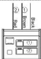
Corridor light with nameplates, 2 names (NIR-32)
Adjusting volume and ringtone settings
For these changes, use the switches and control knobs under the switch cover by removing the cover.

Adjusting volume
To adjust:
Turn the control knob clockwise to increase and counterclockwise to decrease the volume.
Decrease

Increase
Changing the sound type of ringtone
You can change the sound type of ringtone between melody and chime.
ON: Melody
OFF: Chime

To select melody, put switch 5 in UP position.
To select chime, put switch 5 in DOWN position.
Activating/deactivating the automatic volume gain of ringtone
When this function is active, the volume of ringtone increases automatically to the maximum level (low→mid→high) in a 90-second interval.
ON: Disable
OFF: Enable

Todisable, put switch 6 in UP position. Toenable, put switch 6 in DOWN position.

Do not change these switches. They have been preset in the optimum positions.
NOTE: After modifying the settings, press the reset button to apply new settings.
TALK:
This adjusts the volume of audio (sent from the master station) heard at the sub stations.
PRETONE:
This adjusts the volume of notice sound heard at the sub stations.
ALL CALL:
This adjusts the volume of all station paging heard at the sub stations.
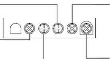
natural_image
Pure electrical circuit lines without any symbolsRECEIVE:
This adjusts the master receive volume. As the basis of this level, you can adjust the receiving volume with the [RECEIVE VOL.] tab on the master station operation panel.
RING TONE:
This adjusts the master volume of ringtone. As the basis of this level, you can adjust the ringtone volume with the RING TONE VOL. tab on the master station operation panel.
Troubleshooting
If the system fails to operate normally, check the following points to determine whether the fault can be corrected by the simple measures suggested. If it cannot be corrected, or if the fault is not listed in the "Symptom" column, disconnect the power cord and contact the system supplier or service center for help.
| Symptom Cause Solution | ||
| The master station will not operate. The power switch on the back of the master station is in the OFF position. | Turn on the power switch. (→ page 21) | |
| The power of all the equipment is off. | ||
| No ringtone | ||
| No communication with sub station. Improper wiring connection | Verify the wiring # to #, M to M, and E to E between master and sub stations. | |
| No communication to sub station. Improper wiring connection | Verify the wiring # to #, M to M, and E to E between master and sub stations. | |
| Call is not held. Improper wiring connection Verify connection of lead wires. | ||
| One way audio An improper device is used for sub station. | Verify a sub station compatible with the NIM system is used. | |
: Individual channel line (#: number)
M: Common line (for microphone)
E: Common line (for earth ground)
Warranty
Aiphone warrants its products to be free from defects of material and workmanship under normal use and service for a period of one year after delivery to the ultimate user and will repair free of charge or replace at no charge, should it become defective upon which examination shall disclose to be defective and under warranty. Aiphone reserves unto itself the sole right to make the final decision whether there is a defect in materials and/or workmanship; and whether or not the product is within the warranty. This warranty shall not apply to any Aiphone product which has been subject to misuse, neglect, accident, power surge, or to use in violation of instructions furnished, nor extended to units which have been repaired or altered outside of the factory. This warranty does not cover batteries or damage caused by batteries used in connection with the unit. This warranty covers bench repairs only, and any repairs must be made at the shop or place designated in writing by Aiphone. This warranty is limited to the standard specifications listed in the operation manual. This warranty does not cover any supplementary function of a third party product that is added by users or suppliers. Please note that any damage or other issues caused by failure of function or interconnection with Aiphone products is also not covered by this warranty. Aiphone will not be responsible for any costs incurred involving on site service calls. Aiphone will not provide compensation for any loss or damage incurred by the breakdown or malfunction of its products during use, or for any consequent inconvenience or losses that may result.
The object area of the EU.
FCC
This device complies with part 15 of the FCC Rules. Operation is subject to the following two conditions: (1) This device may not cause harmful interference, and (2) this device must accept any interference received, including interference that may cause undesired operation.
NOTE: This equipment has been tested and found to comply with the limits for a Class B digital device, pursuant to part 15 of the FCC Rules. These limits are designed to provide reasonable protection against harmful interference in a residential installation. This equipment generates, uses and can radiate radio frequency energy and, if not installed and used in accordance with the instructions, may cause harmful interference to radio communications. However, there is no guarantee that interference will not occur in a particular installation. If this equipment does cause harmful interference to radio or television reception, which can be determined by turning the equipment off and on, the user is encouraged to try to correct the interference by one or more of the following measures:
- Reorient or relocate the receiving antenna.
- Increase the separation between the equipment and receiver.
- Connect the equipment into an outlet on a circuit different from that to which the receiver is connected.
- Consult the dealer or an experienced radio/TV technician for help.
IC
CAN ICES-3 (B)/NMB-3(B)

Providing Peace of Mind
http://www.aiphone.net/

- Contents
- GETTING STARTED 6
- MOUNTING 14
- CONNECTION 18
- SETUP AFTER INSTALLATION ... 30
- APPENDIX....31
- Introduction
- Precautions
- WARNING
- Negligence could result in death or serious injury.
- CAUTION
- Negligence could result in injury to people or damage to property.
- GENERAL PRECAUTIONS
- NOTICES
- System requirements for PC
- System configuration
- ■ Maximum number of stations in a single system
- ■ Communication methods
- Package contents and dimensions
- Master station
- Sub station, call button, wall jack
- Ceiling speaker, ceiling microphone
- Corridor light, reset button
- Software
- ■ Ceiling speaker (NI-LB)
- ■ Ceiling microphone (NI-SB)
- NOTE:
- ■ Wall jack (NIR-HP, NIR-1, NIR-MB, NIR-7BS)
- Bathroom call button (NIR-7W, NIR-7HW)
- ■ Sub station, surface mount (NI-BA)
- When setting NI-BA on a desk
- ■ Sub station, fl ush mount (NI-JA)
- ■ Wall jack (NIR-HPF)
- ■ Corridor light with nameplate (NIR-31, NIR-32, NIR-34)
- Connection wiring diagram (outline)
- ■ Master station terminal marking
- ■ Meanings of symbols
- Handling cables
- Notes about handling cables
- Notes on cables
- ■ How to connect or disconnect stranded wires.
- ■ Note about wire-to-wire connection.
- Connection wiring diagram (details)
- Connecting to the master station
- Procedure
- Multiple-user room examples of using the ceiling speaker (NI-LB) and the ceiling microphone (NI-SB)
- Multiple-user room examples of using the ceiling speaker (NI-LB) and not using the ceiling microphone (NI-SB)
- When using equipment without microphone (no communication is possible)
- When not using a corridor light
- Examples of using the bathroom call buttons (NIR-7W or NIR-7HW)
- Single room examples of using the surface mount sub station (NI-BA)
- Examples of using the fl ush mount sub station (NI-JA)
- When using a corridor light and reset button
- Notes about connecting to a corridor light with nameplate (NIR-31, NIR-32, NIR-34)
- e.g.
- Wiring example
- Adjusting volume and ringtone settings
- Adjusting volume
- To adjust:
- Changing the sound type of ringtone
- Activating/deactivating the automatic volume gain of ringtone
- TALK:
- PRETONE:
- ALL CALL:
- RECEIVE:
- RING TONE:
- Troubleshooting
- : Individual channel line (#: number)
- Warranty
- FCC
- IC
Brand : Aiphone
Model : NIM-40B
Category : Home Automation