
ISC-D733-TS2 - Detector Dahua Technology - Free user manual and instructions
Find the device manual for free ISC-D733-TS2 Dahua Technology in PDF.


User questions about ISC-D733-TS2 Dahua Technology
0 question about this device. Answer the ones you know or ask your own.
Ask a new question about this device
Download the instructions for your Detector in PDF format for free! Find your manual ISC-D733-TS2 - Dahua Technology and take your electronic device back in hand. On this page are published all the documents necessary for the use of your device. ISC-D733-TS2 by Dahua Technology.
USER MANUAL ISC-D733-TS2 Dahua Technology
Walk-through Metal Detector
User's Manual

natural_image
Abstract geometric composition with gray and blue color blocks (no text or symbols)Foreword
General
This manual introduces the structure, installation, and configuration of the Walk-through Metal Detector (hereinafter referred to as "the Detector"). Read carefully before using the Detector, and keep the manual safe for future reference.
Safety Instructions
The following signal words might appear in the manual.
| Signal Words Meaning | ||
 | DANGER | Indicates a high potential hazard which, if not avoided, will result in death or serious injury. |
 | WARNING | Indicates a medium or low potential hazard which, if not avoided, could result in slight or moderate injury. |
 | CAUTION | Indicates a potential risk which, if not avoided, could result in property damage, data loss, reductions in performance, or unpredictable results. |
 | TIPS | Provides methods to help you solve a problem or save time. |
 | NOTE | Provides additional information as a supplement to the text. |
Revision History
| Version | Revision Content | Release Time |
| V1.0.0 | First release. | March 2022 |
Privacy Protection Notice
As the device user or data controller, you might collect the personal data of others such as their face, fingerprints, and license plate number. You need to be in compliance with your local privacy protection laws and regulations to protect the legitimate rights and interests of other people by implementing measures which include but are not limited: Providing clear and visible identification to inform people of the existence of the surveillance area and provide required contact information.
Interface Declaration
This manual mainly introduces the relevant functions of the device. The interfaces used in its manufacture, the procedures for returning the device to the factory for inspection and for locating its faults are not described in this manual. Please contact technical support if you need information on these interfaces.
About the Manual
- The manual is for reference only. Slight differences might be found between the manual and the product.
- We are not liable for losses incurred due to operating the product in ways that are not in compliance with the manual.
- The manual will be updated according to the latest laws and regulations of related jurisdictions.
For detailed information, see the paper user's manual, use our CD-ROM, scan the QR code or visit our official website. The manual is for reference only. Slight differences might be found between the electronic version and the paper version.
- All designs and software are subject to change without prior written notice. Product updates might result in some differences appearing between the actual product and the manual. Please contact customer service for the latest program and supplementary documentation.
- There might be errors in the print or deviations in the description of the functions, operations and technical data. If there is any doubt or dispute, we reserve the right of final explanation.
- Upgrade the reader software or try other mainstream reader software if the manual (in PDF format) cannot be opened.
- All trademarks, registered trademarks and company names in the manual are properties of their respective owners.
- Please visit our website, contact the supplier or customer service if any problems occur while using the device.
- If there is any uncertainty or controversy, we reserve the right of final explanation.
Important Safeguards and Warnings
This chapter describes the contents covering proper handling of the Detector, hazard prevention, and prevention of property damage. Read these contents carefully before using the Detector, and comply with them when using.
Transportation Requirements

Transport the Detector under the allowed humidity and temperature conditions.
Storage Requirements

- Keep the Detector away from dampness, dust or soot.
- Store the Detector under the allowed humidity and temperature conditions.
Installation Requirements

- Do not place or install the Detector in a place exposed to sunlight or near the heat source.
- Keep the Detector installed horizontally on a stable place to prevent it from falling.
- Install the Detector in a well-ventilated place, and do not block the ventilation of the Detector.
Operation Requirements

- Do not drop or splash liquid onto the Detector, and make sure that there is no object filled with liquid on the Detector to prevent liquid from flowing into the Detector.
- Operate the Detector within the rated range of power input and output.
- Do not disassemble the Detector.
- Use the Detector under the allowed humidity and temperature conditions.
Maintenance Requirements

WARNING
- Use the battery of specified manufacturer; otherwise there might result in explosion. When replacing battery, make sure that the same type is used. Improper battery use might result in fire, explosion, or inflammation.
● Always replace with the same type of batteries. - Use the recommended power cables in the region and conform to the rated power specification.
- Use the power adapter provided with the Detector; otherwise, it might result in people injury and device damage.

- The power source shall conform to the requirement of the Safety Extra Low Voltage (SELV) standard, and supply power with rated voltage which conforms to Limited Power Source requirement according to IEC 60068-2. For specific power supply requirements, refer to device labels.
- Connect the Detector (I-type structure) to the power socket with protective earthing.
- The appliance coupler is a disconnection device. When using the coupler, keep the angle for easy operation.
Table of Contents
Foreword....
Important Safeguards and Warnings....III
1 Overview....1
1.1 Introduction ...... 1
1.2 Technical Advantages .... 1
2 Structure 2
2.1 Dimensions....2
2.2 Host Box 3
2.3 Ports 4
2.4 UPS....6
3 Installation....8
3.1 Checklist....8
3.2 Environmental Requirements 8
3.3 Installing Detector 9
3.4 Installing Thermal Camera....11
3.5 Multiple Walk-through Site Installation....12
4 Configuration....14
4.1 Login and Changing Password....14
4.1.1 Login 14
4.1.1.1 First-time Login....14
4.1.1.2 Not First Time Login 15
4.1.2 Changing Password ...... 15
4.2 Operation Access ...... 16
4.3 Desktop....16
4.4 Setting Sensitivity....18
4.4.1 Setting Sensitivity Manually....18
4.4.2 Setting Sensitivity Automatically....19
4.4.3 Setting Security Level 20
4.5 Setting Frequency....20
4.5.1 Setting Frequency Manually....20
4.5.2 Setting Frequency Automatically 21
4.5.3 Setting Extended Frequency....22
4.6 Setting Program 22
4.6.1 Preset Programs 22
4.6.2 Custom Programs 25
4.7 Setting Alarms....26
4.7.1 Alarm Settings....26
4.7.2 Random Alarm....27
4.7.3 Alarm Tone and Volume 27
4.8 Setting IR Mode 28
4.9 Setting Counter 29
4.9.1 Viewing Counter Data 29
4.9.2 Searching for Count Data 29
4.10 System Settings 30
4.10.1 Setting Network....30
4.10.2 Setting Desktop 31
4.10.3 Setting Time 32
4.10.4 Setting Screen Parameters 32
4.10.5 Setting Language....33
4.11 Maintenance....33
4.11.1 IR Diagnosis....33
4.11.2 Factory Reset 34
4.11.3 Self Inspection 34
4.11.4 Viewing Version....35
5 Camera Configuration ....36
5.1 Logging in to Camera Web....36
5.2 Enabling Smart Plan....36
5.3 Configuring Temperature Monitoring 36
5.4 Configuring Smart Channel....38
5.5 Setting Baud Rate....39
6 Upgrading Detector 40
6.1 Configuring Network....40
6.2 Viewing Current Version....41
6.3 Upgrading Detector 41
7 FAQ 44
Appendix 1 Cybersecurity Recommendations....47
1 Overview
1.1 Introduction
With its modular design and strong anti-interference capabilities, the Detector provides optimal performance. It has a user-friendly interface, and is easy to transport and install. Designed with a 7-inch touch screen, it offers remote control and touch screen control, and is also built of specialized and strong materials that make it suitable for various environments.
The Detector detects metal objects using electromagnetic fields, and triggers sound and light alarms when a person is detected to be carrying a metal object. It can cover 33 detection zones, adapts easily to a wide variety of environments, and is built with high-frequency signal generators, a host box, signal receivers, and IR sensors.
The Detector is suitable for security screening of prohibited metal items in railway stations, bus stations, metro rail transit, government buildings, exhibition centers, sports meetings, and schools.
1.2 Technical Advantages
- Multiple applications: Supports 90 programs for different application scenarios, detects magnetic and non-magnetic metals, and filters innocuous metal objects.
- Various alarms: Supports sound and light alarm. Alarm tone, volume, and duration can be adjusted.
- Pass statistics search: Searches for the number of passes by hour or day.
- Network connection: Supports parameter configuration through the network, and supports platform management.
- Cyber security: Supports 2-level users. The operator and the administrator have different access. Ensures cyber security by strict password verification.
- Self-test: Supports manual/automatic self-test.
- Detection capacity: 60–100 persons/min.
- Quick installation and configuration: Supports automatic sensitivity setting and frequency search, and convenient program selection.
- Uninterruptible power supply: Supports sealed lead-acid battery (optional), and automatically detects the battery status for cyclic charging. The charging will stop automatically when the battery is fully charged.
- Traffic lights: Supports traffic lights that inform pedestrians whether the pass is allowed or not.
- Multiple languages: English, Russian, Indonesian, and Turkish are available.
- Two control methods: The 7-inch full color LCD supports touch screen control and remote control.
- Safety: Complies with the EMC Electromagnetic Radiation Standards by using very low frequency electromagnetic fields. No harm caused to pacemakers, pregnant women, or magnetic storage devices.
2 Structure
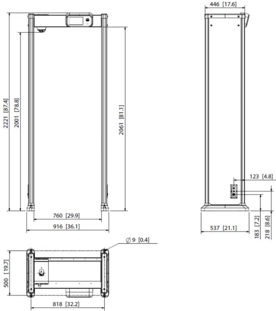
2.1 Dimensions
Figure 2-1 Dimensions (unit: mm [inch])
2.2 Host Box
Figure 2-2 Host box
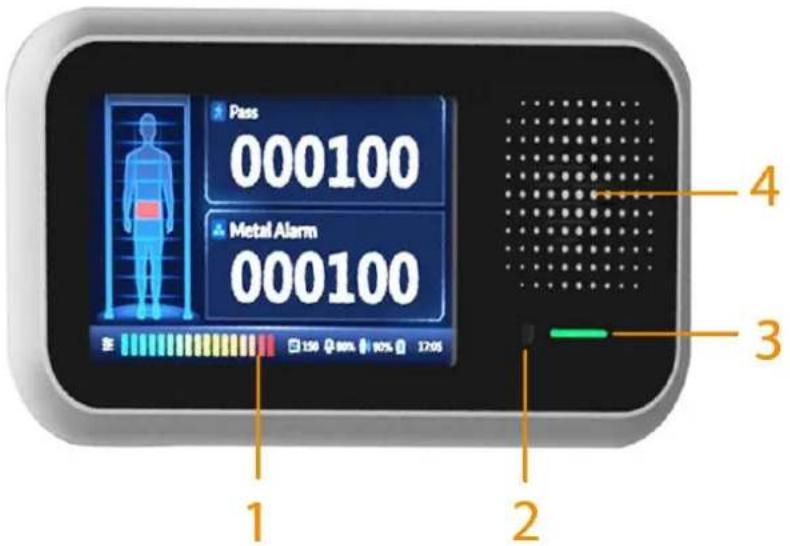
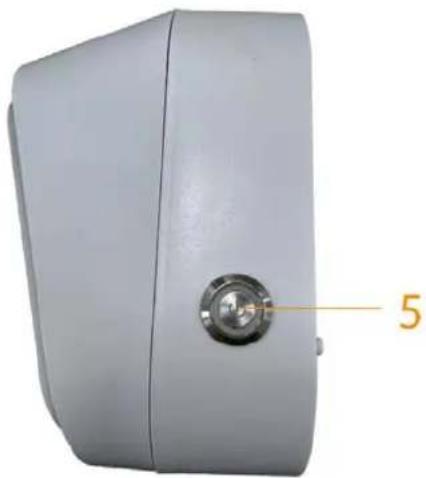
Figure 2-3 Power switch
natural_image
Exterior view of a gray rectangular device with a circular button and a numbered label '5' pointing to the side (no other text or symbols visible)Table 2-1 Host box description
| No. Name Description | ||
| 1 LCD 7-inch full color touch screen LCD. | ||
| 2 IR Receiver Receives IR signal. | ||
| 3 Indicator | Solid green during startup.Flashes green after startup. | |
| 4 Speaker Outputs audio alarms. | ||
| 5 | Power switch | Press the button to turn on or off the host box. |
2.3 Ports
Figure 2-4 Host ports (1)
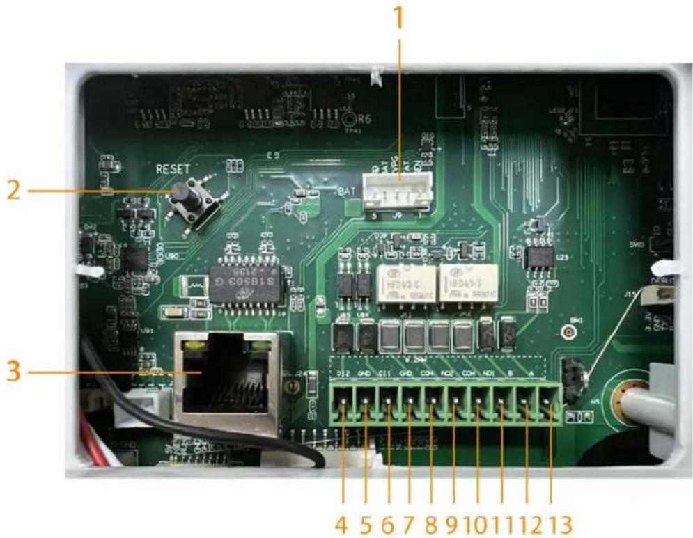
Figure 2-5 Host ports (2)
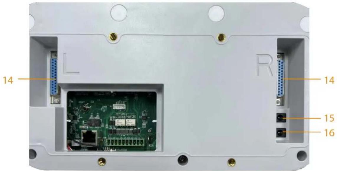
Figure 2-6 Panel ports
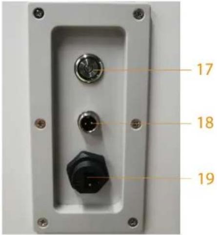
Table 2-2 Port description
| No. Name Description | ||
| 1 | Data port | Connects to the data port on the UPS board. |
| 2 Reset button | Press and hold the button for more than 5 s to restore the Detector to factory default.⚠️Proceed with caution. | |
| 3 | Ethernet port | Connects to network with network cable. |
| 4 | Alarm in 2 | Receives the signal of external alarm source. |
| 5 | ||
| 6 | Alarm in 1 | |
| 7 | ||
| 8 | Alarm out 2 | Outputs alarm signal to alarm device. |
| 9 | ||
| 10 | Alarm out 1 | |
| 11 | ||
| 12 | RS-485 B | Controls external devices. EdinburghConnect A and B cables (which both control RS-485) to devices such as thermal cameras.If there are muptiple thermal camera decoders, connect A and B cables to 120 Ω resistors. |
| 13 | RS-485 A | |
| 14 | DB25 | Signal port for metal detection. |
| 15 Power in | Inputs 12 VDC power. Be sure to supply power as instructed in the manual.⚠️Detector damage might occur if power is not supplied correctly. | |
| 16 Power out | • Outputs 12 VDC power.• Supports connecting to a thermal camera. | |
| No. Name | Description | |
| 17 | Power switch | After power on, press this button to start the Detector. |
| 18 | Power in | Inputs 12 VDC power. |
| 19 | Ethernet port | Connects to a network cable. |
2.4 UPS
Uninterruptible Power Supply (UPS) provides emergency power to the Detector when the input power source fails.
Figure 2-7 UPS board port
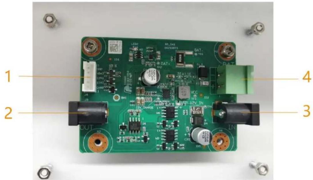
Table 2-3 Port description
| No. Name Description | ||
| 1 | Data port | Reads the charging status of the sealed lead-acid (SLA) battery. |
| 2 | Power out | Outputs 12 VDC power. |
| 3 Power in | Inputs 12 VDC power.⚠️Detector damage might occur if power is not supplied correctly. | |
| 4 | Storage battery in | Connects to a 12 V SLA battery. |
Function of the UPS Board
The SLA battery is connected to the host box through the port 1. When port 3 is connected to 12 V power supply, the UPS board supplies the 12 VDC power to the host box, and at the same time charges the SLA battery through port 4.
When the 12 VDC power of port 3 fails, the UPS board immediately switches the DC power of the SLA battery to discharge mode and supplies power to the host box. The host box accesses whether the battery is connected, charging or discharging through the data port (port 1).
Battery Requirements
Must be a 12 V SLA battery. No capacity limit.
Battery Charging Time
The constant charging current is 500 mA, so the charging time is: h = C / 500 mA × 1.2.
Assuming the capacity of a SLA battery is 2 Ah, its charging time will be: h = 2 Ah / 0.5 A× 1.2 = 4.8 h.
SLA Battery Life
• Capacity of the SLA battery: C. Unit: Ah
● Power consumption of the Detector: Min: 15.5 W; Max: 26.5 W
• Voltage of the Detector: 12 V
Assuming the capacity of the SLA battery is 7 Ah, the battery life will be:
- Min: H = C / A = C / (P / U) = 7 / (26.5 / 12) = 3.17 h
- Max: H = C / A = C / (P / U) = 7 / (15.5 / 12) = 5.42 h
3 Installation
3.1 Checklist
Table 3-1 Checklist
| No. List Description | |||
| 1 Overall packaging | Appearance Obvious damage | ||
| Packaging Accidental impact | |||
| Accessories Complete or not | |||
| 2 Host | Appearance Obvious damage | ||
| Model | Whether consistent with the order contract | ||
Table 3-2 Packing list
| Name Quantity | |
| Door panel 2 | |
| Host box 1 | |
| Beam 2 | |
| Power cord (power input) 1 | |
| DB25 cable 2 | |
| Fixing screws (M6 × 16) 4 | |
| Fixing screws (M8 × 80) 8 | |
| Remote control 1 | |
| Wrench 1 | |
| Dry cell | 2 |
| Key | 1 |
| Network cable | 1 |
| Accessory cable | 1 |
| AC/DC power adapter | 1 |
| Thermal camera | 1 |
| Thermal camera fixing bracket | 1 |
| Thermal camera fixing screws | 5 |
3.2 Environmental Requirements
- The ground is flat and sturdy The ground should be flat and firmly supporting to prevent vibration. If there is a vibrating metal structure under the ground, there can be unnecessary alarm when people pass through the metal detector. Do not install the Detector on a metal ground.
- Keep away from fixed metal objects
Large metal objects that are fixed or immobile should be at least 50 cm away from the Detector (detecting large metal objects) because they might make the Detector more susceptible to vibration.

The distance in this section is the recommended distance. The actual installation distance depends on the installation site conditions.
- Keep away from moving metal objects
Large moving metal objects should be kept 0.5 m to 2 m away from the Detector to avoid false alarms. Depending on the size of the metal object, the distance between the moving metal object and the Detector might vary.
- Keep away from radioactive electronic interference
The distance between the electronic interference source and the receiving coil should be as large as possible. The recommended minimum distance is 0.5 m to 4 m. However, the actual distance needs to be based on specific circumstances. For example, you can go through a metal detector with a source of interference until the best position is found. Interference can occur from electronic control panels, radios and computers, image displays, high-power motors and transformers, AC wires, transistor control circuits, flash fluorescent tubes, arc welding equipment, and more.
- Keep away from conductive electronic interference
Connect the power cable to a line that is not connected to other large loads, such as high-power motors, because they can cause a large power or voltage shock in the line.
3.3 Installing Detector
Step 1 Open the packing box and take out the accessories.
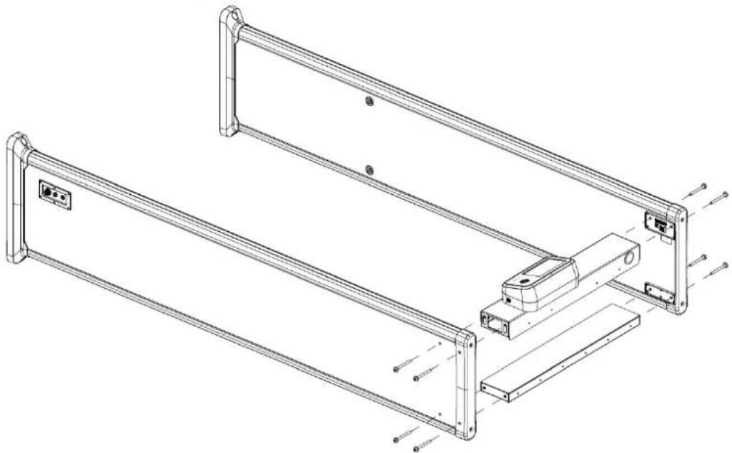
Step 2 Open the rear beam with the key, and then attach the host box to the rear beam with eight M6 × 16 screws. Close the rear beam.
Figure 3-1 Attach host box
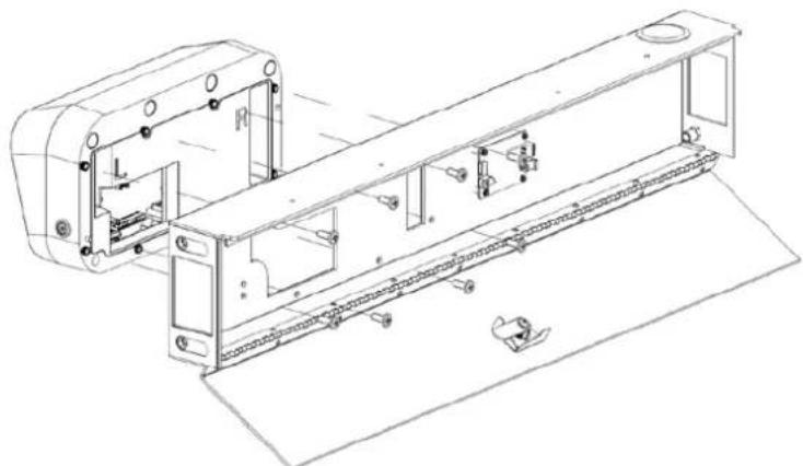
natural_image
Technical line drawing of a mechanical assembly with no visible text or symbolsStep 3 Attach the two beams to the two door panels with eight M8 × 8 screws.
Figure 3-2 Attach beams and panels
natural_image
Technical line drawing of a mechanical frame assembly with mounting brackets and mounting holes (no text or symbols)Step 4 Stand the Detector up, and open the back cover.
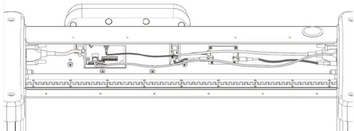
Step 5 Connect the cables.
1) Connect one end of the two DB25 cables to the host box and the other to the door panel.
2) Connect one end of the data cable to the data port on the motherboard and the other to the data port on the battery charging board.
3) Connect one end of the network cable to the motherboard and the other to either side of the door panel.
4) Connect one end of the first power cable to the IN port of the motherboard and its other end to the OUT port of the battery charging board. Afterwards, connect one end of the second power cable to the IN port of the battery charging board, and its other end to the power port of either door panel.
Figure 3-3 Connect cables
natural_image
Technical line drawing of a mechanical assembly with internal components and mounting brackets (no text or symbols)Step 6 Close the back cover of the rear beam.
Step 7 Connect the power supply to the door panel, and then turn on the power switch to start the Detector. Connect a network cable as needed.
3.4 Installing Thermal Camera
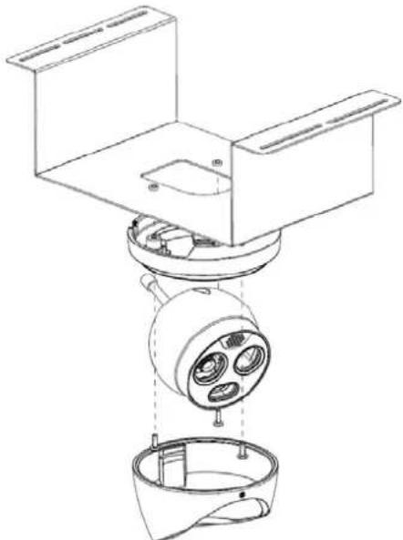
Step 1 Use the Allen wrench to loosen the screws to disassemble the camera into three parts.
Step 2 Attach the camera base to the fixing bracket with three M4 × 16 screws. Place the camera and its cover back in the original position.
Figure 3-4 Assemble camera
natural_image
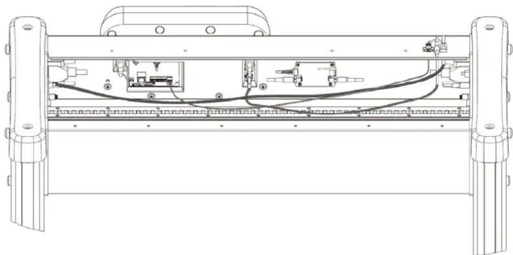
Technical line drawing of a mechanical assembly with internal components (no text or symbols)Step 3 Open the back cover of the Detector, take out the power cord and RS-485 cable from the accessories, and then connect them to the ports of the Detector. Run the power cord and the RS-485 cable through the opening of the back cover.
Step 4 (Optional) If you need to connect the camera to an external network such as a LAN, connect a network cable (not provided) to the door panel, and then run it through the opening of the back cover.
Figure 3-5 Connect camera cables
natural_image
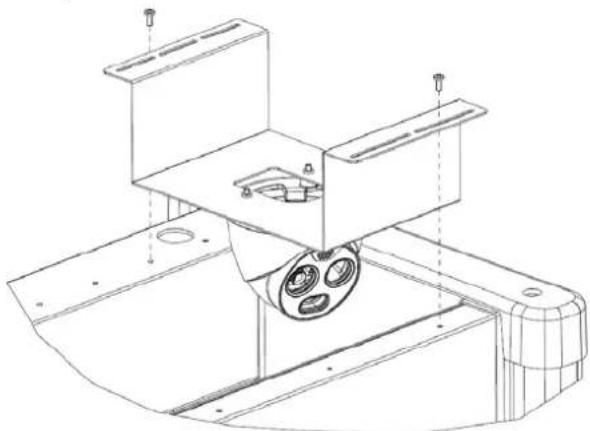
Technical line drawing of a mechanical assembly with internal components and mounting feet (no text or symbols)Step 5 Close the back cover and place the bracket together with the camera between the two beams. Move the camera to a suitable position and secure it with two to three M4 × 16 screws.
Figure 3-6 Place and fix the camera
natural_image
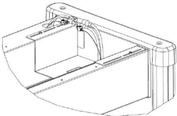
Technical line drawing of a mechanical assembly with mounting brackets and a central component (no text or symbols)Step 6 Connect the power cord, RS-485 cable, and the network cable to the corresponding ports of the Detector and the camera.
Figure 3-7 Connect camera cables
natural_image
Technical line drawing of a mechanical housing or enclosure component (no text or symbols)Step 7 Adjust the camera to a suitable angle.
3.5 Multiple Walk-through Site Installation
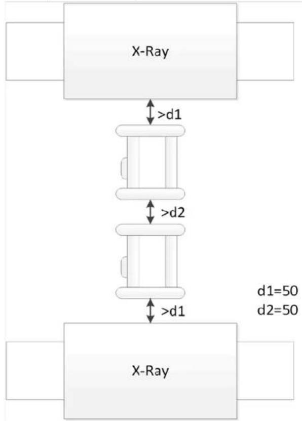
When installing multiple devices, space the devices at least 50 cm, and also space the device and X-ray security screening machine larger than 50 cm. This recommended spacing can make the little metal objects (such as coin) detected. If you install the devices with space smaller than 50 cm, there might be false alarm. If the spacing needs to be shorten because of limited installation site, you need to adjust the frequency, lower the security level and sensitivity according to the actual situation; otherwise, small metal objects might not be detected.
Figure 3-8 Multiple walk-through detectors site installation
flowchart
graph TD
    A["X-Ray"] -->|d1>| B["Component"]
    B -->|d2=50| C["X-Ray"]
    style A fill:#f9f,stroke:#333
    style C fill:#bbf,stroke:#333
4 Configuration

The LCD display might be different depending on the model that you purchased.
4.1 Login and Changing Password
4.1.1 Login
You can set the parameters as needed. To prevent unauthorized modifications, password protection is in place.
Every time you go to the menu from the desktop, you need to enter the password.
4.1.1.1 First-time Login
Step 1 Power on the Detector, press the power button, and then wait for about 5 s. The system displays Booting Up.
Step 2 Select a language. English, Russian, Indonesian, and Turkish are available.
Step 3 Tap Next to set the date and time.
Step 4 Tap Finish to enter the desktop.
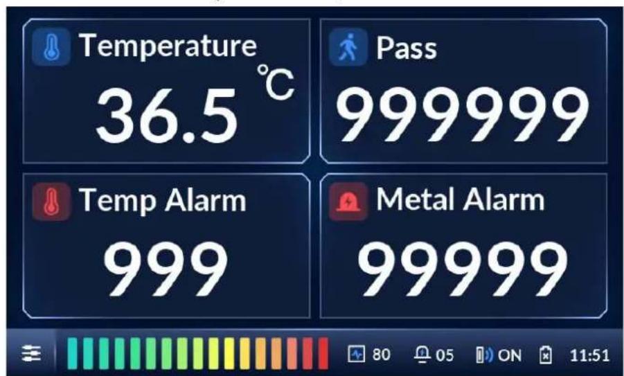
Figure 4-1 Desktop
Step 5 Tap on the lower-left of the desktop to go to the login screen.
Step 6 Select Admin or Operator, and then enter the corresponding password.
- The password for Admin is admin123 by default.
- The password for Operator is operator123 by default.

We recommend that you change the password.
Figure 4-2 Login
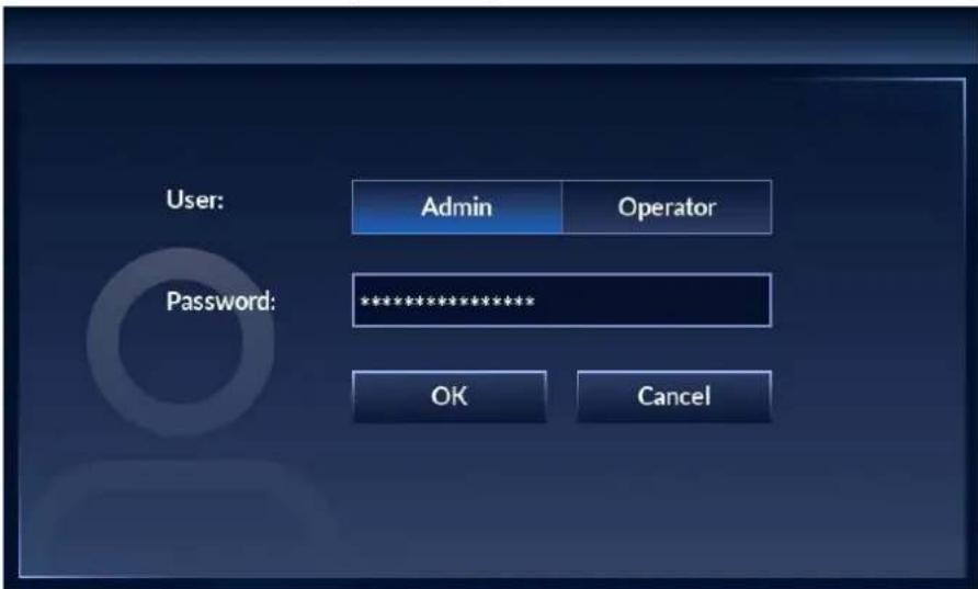
Step 7 Tap OK to go to the menu.
Figure 4-3 Menu
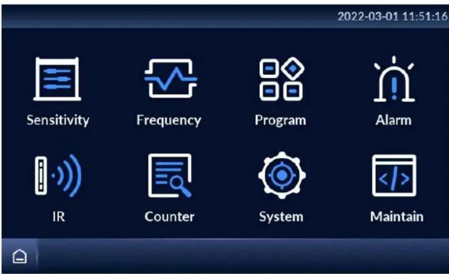
4.1.1.2 Not First Time Login
The desktop is displayed after the Detector is started.
Step 1 Power on the Detector, press the power button, and then wait for about 5 s. The system displays Booting Up.
The desktop is displayed.
Step 2 Tap on the lower-left of the desktop to go to the login screen.
Step 3 Select Admin or Operator, and then enter the corresponding password.
Step 4 Tap OK to go to the menu.
4.1.2 Changing Password
Change your password regularly to ensure system security.
Step 1 Tap ≡ on the lower-left of the desktop, and then enter the password to go to the menu.
Step 2 Select System > Password.
Step 3 Enter your old password, new password, and then confirm your new password.

The password must consist of 8 to 16 digits of both letters and numbers.
Figure 4-4 Change password
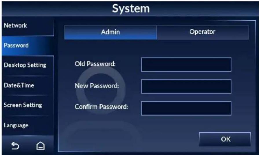
Step 4 Tap OK.
Step 5 The system prompts
Successfully modified the password.
4.2 Operation Access
To ensure security and avoid data tampering, the admin account and the operator account are designed with different operation access.
- The admin account has full access to all settings.
- The operator account only has access to changing operator password, setting custom program, adjusting the volume, clearing counter data, and searching for counter record.
4.3 Desktop
There are two modes of desktop: metal alarm desktop and temperature alarm desktop.
Tap ≡ on the lower-left of the desktop, and then enter the password to go to the menu. Tap
System > Desktop Setting to switch desktop. For details, see "4.10.2 Setting Desktop".
Figure 4-5 Metal alarm desktop
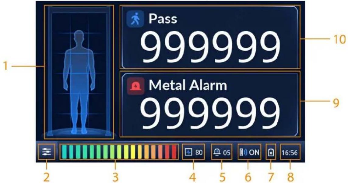
Figure 4-6 Temperature alarm desktop
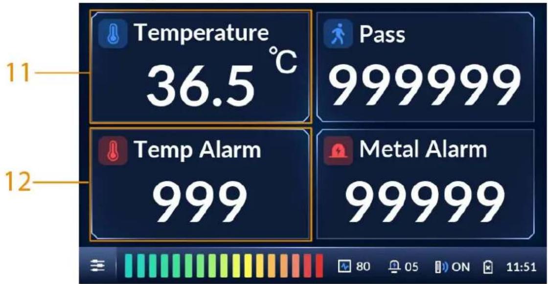
Table 4-1 Desktop parameters
| No. Description | |
| 1 | Location of metal objects. The detector panel can be set to 6, 12, or 18 zones. |
| 2 | Tap , and then enter the password to go to the menu to configure parameters. |
| 3 Intensity of metal detection. | |
| 4 Frequency. | |
| 5 Alarm volume. | |
| 6 | IR status. For details, see "4.7.1 Alarm Settings". |
| 7 | The status of the SLA battery.● :  charging.● : charging.● :  / charged.● : / charged.● :  charging.● : [3XBA] battery. charging.● : [3XBA] battery. |
| 8 Current time. | |
| 9 Total number of metal alarms. | |
| 10 | Number of people walking through the Detector. |
| 11 | Body temperature of the person walking through. |
| 12 | Number of temperature alarms. |
4.4 Setting Sensitivity
Sensitivity relates to metal detection capability.
You can manually set the sensitivity of zones or automatically set the sensitivity by carrying metals and walking through the Detector. You can change the number of zones, and set the security level.
When both the defined threshold of security level and sensitivity are reached, an alarm will be triggered.
4.4.1 Setting Sensitivity Manually
You can adjust the sensitivity of individual zones, or set a same sensitivity for all zones.
Procedure
Step 1 Tap ≡ on the lower-left of the desktop to go to the login screen.
Step 2 Select Sensitivity > Sensitivity.
Figure 4-7 Set sensitivity
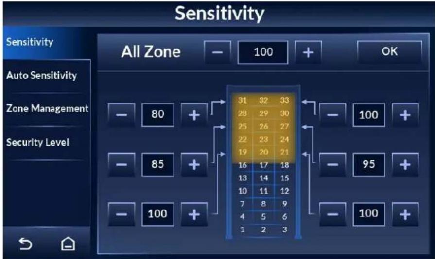
Step 3 Tap + or - to set the sensitivity of each zone.
You can set a same sensitivity for all zones, or set the sensitivity of individual zones. The sensitivity range is 0–255. At higher sensitivity settings, smaller metal objects are detected. Conversely, at lower sensitivity settings, only larger metal objects are detected. Keep in mind that the sensitivity should be set high enough so that the smallest forbidden objects are detected.
- Set a same sensitivity for all zones: Adjust the sensitivity behind All Zone, and then tap OK.
- Set the sensitivity of individual zones: Adjust the sensitivity of individual zones where the arrows point to, and the change takes effect immediately.
4.4.2 Setting Sensitivity Automatically
You can automatically set the sensitivity of all zones by walking through the Detector with metal objects.
Step 1 Tap ≡ on the lower-left of the desktop to go to the login screen.
Step 2 Select Sensitivity > Auto Sensitivity.
Figure 4-8 Set automatic sensitivity
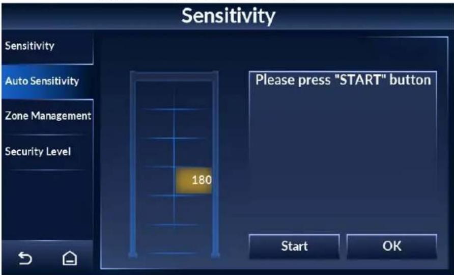
Step 3 Tap Start, and then walk through the Detector with metal objects for at least three times, so that three sensitivity values are recorded.
Step 4 Tap OK.
The maximum sensitivity automatically becomes the sensitivity of all zones. You can view the sensitivity by tapping the Sensitivity tab.
4.4.3 Setting Security Level
Security level is the detection sensitivity of the Detector as a whole.

Sensitivity only works for each individual zone. For a metal object to trigger alarm, both the sensitivity and the security level need to reach the alarm threshold.
Step 1 Tap on the lower-left of the desktop to go to the login screen.
Step 2 Select Sensitivity > Security Level.
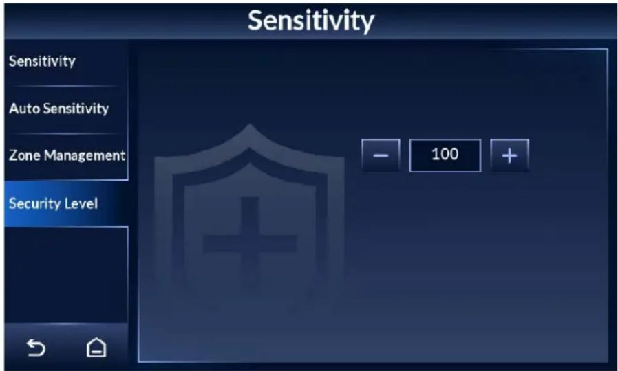
Step 3 Tap + or - to adjust the security level.
It ranges from 1 to 100. The higher the value is, the more secure and sensitive the whole Detector is.
When both the defined threshold of security level and sensitivity are reached, an alarm will be triggered.
Figure 4-9 Set security level
4.5 Setting Frequency
For multiple walk-through metal detector operation, set each of them to a different frequency to reduce mutual interference.
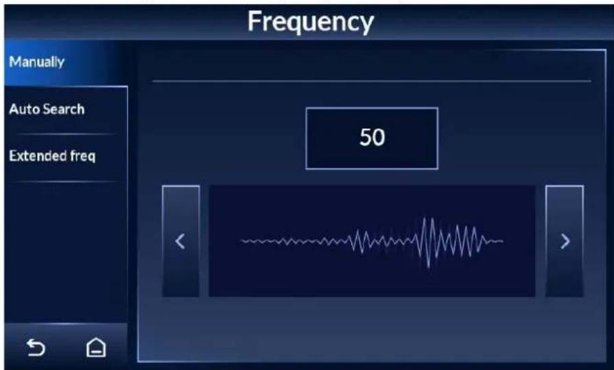
4.5.1 Setting Frequency Manually
Step 1 Tap ≡ on the lower-left of the desktop to go to the login screen.
Step 2 Select Frequency > Manually.
Step 3
Tap
or
to adjust frequency.
The frequency range is 1 to 20 by default, and can be extended to 100. For details, see "4.5.3 Setting Extended Frequency".
Figure 4-10 Set frequency manually
4.5.2 Setting Frequency Automatically
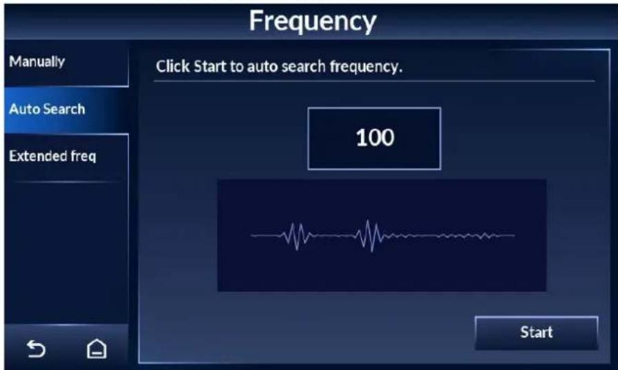
Based on the environment, the Detector automatically searches for a suitable frequency to reduce interference by other working walk-throughs in close proximity.
Step 1
Tap

on the lower-left of the desktop to go to the login screen.
Step 2 Select
Frequency > Auto Search.
Step 3 Tap
Start, and then a pop-up displays on the screen.
Step 4 Tap
OK, and then the Detector starts to search for a frequency automatically.
The process takes about 40 s, during which no operation will be responsive.
Figure 4-11 Automatic search
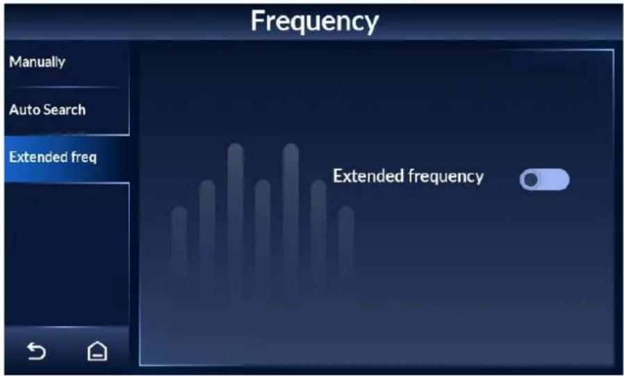
4.5.3 Setting Extended Frequency
For multiple walk-through metal detector operation, you can extend the frequency range to reduce interference.
Step 1 Tap on the lower-left of the desktop to go to the login screen.
Step 2 Select Frequency > Extended freq.
Step 3 Tap to enable extended frequency, and tap to disable it.
The extended frequency ranges from 1 to 100. It is disabled by default.
Figure 4-12 Set extended frequency
4.6 Setting Program
Each program has its own set of sensitivity, and is therefore different in metal detection capability. After setting program, the default sensitivity will change correspondingly. A total of 90 programs are available, including 80 preset and 10 custom ones.
4.6.1 Preset Programs
Each preset program is designed with a set of sensitivity suitable for a certain scenario.
Step 1 Tap ≡ on the lower-left of the desktop to go to the login screen.
Step 2 Select Program > Preset.
Step 3 Select a program that suit your application scenario. Tap ◀ or ▶ to go to the previous or next page.
Eighty preset programs are available. Each program is designed with a set of parameters. You can adjust the parameters as needed.

The system will save your adjustment disregard of restart.
Figure 4-13 Preset program (1)
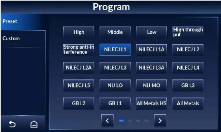
Figure 4-14 Preset program (2)
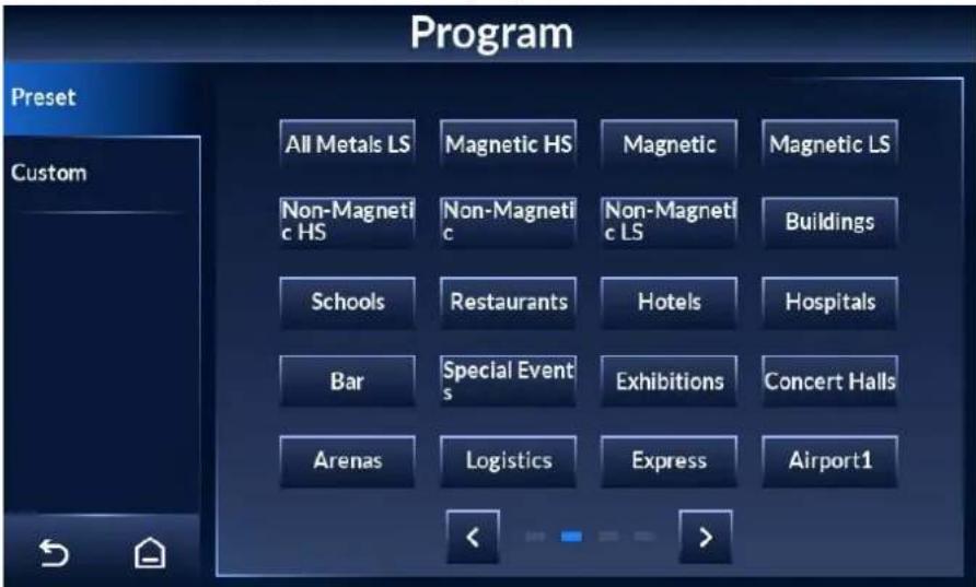
Figure 4-15 Preset program (3)
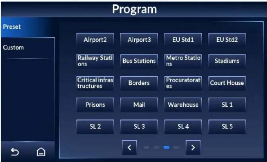
Figure 4-16 Preset program (4)
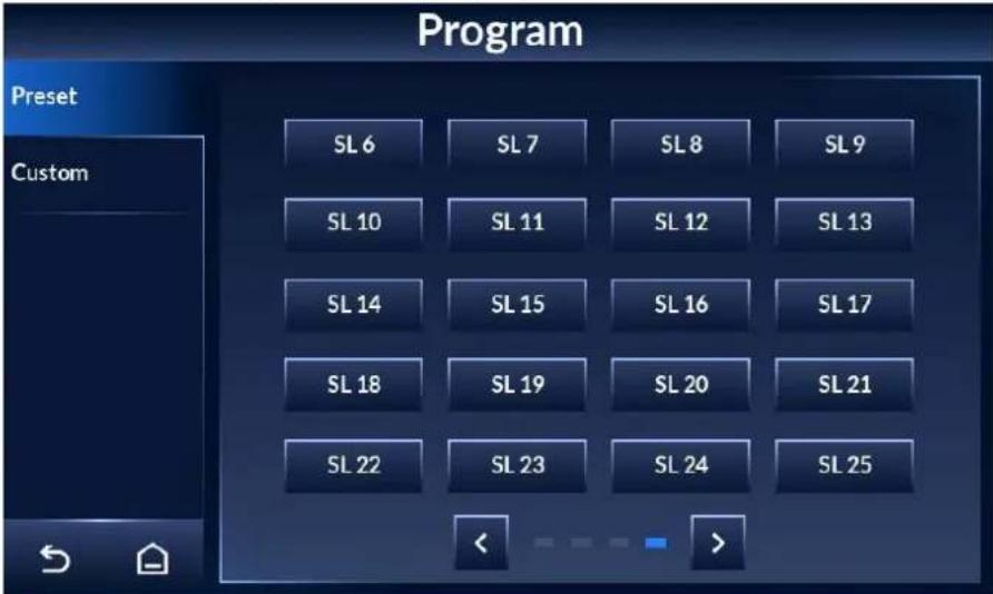
Table 4-2 Preset program description
| Name Description | |
| High, All Metals HS, Critical infrastructures, Borders, Procuratorates, Court House, Prisons, and Mail | Highest detection level. Detects all dangerous objects. |
| Middle, All Metals, and Buildings | Medium detection level. Detects forbidden objects such as small guns. |
| Low, and All Metals LS | Low detection level. Detects strictly forbidden objects such as guns, and filters glasses, watches, coins, and other small metal objects. |
| High throughput, and Strong anti-interference | Suitable for use in complex environments with strong anti-interference capability and low sensitivity. Detects strictly forbidden objects such as guns, and filters glasses, watches, coins, and other small metal objects. |
| NILECJ L1 For L1 of NILECJ 0601.00. | |
| NILECJ L1A | For L1 Augment of NILECJ 0601.00. |
| NILECJ L2 For L2 of NILECJ 0601.00. | |
| NILECJ L2A | For L2 Augment of NILECJ 0601.00. |
| NILECJ L3 For L3 of NILECJ 0601.00. | |
| NILECJ L3A | For L3 Augment of NILECJ 0601.00. |
| NILECJ L4 For L4 of NILECJ 0601.00. | |
| NILECJ L5 | For L5 of NILECJ 0601.00. |
| NIJ LO | For Large object of NIJ0601.02. |
| NIJ MO | For Medium object of NIJ0601.02. |
| GB3 For level III of GB15210:2018. | |
| GB2 For level II of GB15210:2018. | |
| GB1 | For level I of GB15210:2018. |
| Schools, Restaurants, Hotels, Hospitals, Bar, Special Events, Exhibitions, Concert Halls, Arenas, Railway Stations, Bus Stations, Metro Stations, and Stadiums | Suitable for use in places with large people flow. Detects forbidden objects such as small guns, and filters glasses, watches, coins, and other small metal objects. |
| Logistics, Express, and Warehouse | Detects small guns and knives, and filters glasses, watches, coins, and other small metal objects. |
| Airport3 | Detects small guns and knives, and filters glasses, watches, coins, and other small metal objects. |
| Airport2, EU Std2 | Detects small guns and knives, and filters glasses, watches, coins, and other small metal objects. |
| Airport1, EU Std1 | Detects small guns and knives, and filters glasses, watches, coins, and other small metal objects. |
| Magnetic HS | Filters non-magnetic metals. Highest detection level. Detects all dangerous objects. |
| Magnetic | Filters non-magnetic metals. Medium detection level. Detects forbidden objects such as small guns. |
| Magnetic LS | Filters non-magnetic metals and small metal objects such as glasses, watches, and coins. Low detection level. Detects strictly forbidden objects such as guns. |
| Non-Magnetic HS | Filters magnetic metal. Highest detection level. Detects all dangerous objects. |
| Non-Magnetic | Filters magnetic metals. Medium detection level. Detects dangerous non-magnetic metal objects and small guns. |
| Non-Magnetic LS | Filters magnetic metals and small metal objects such as glasses, watches, and coins. Low detection level. Detects strictly forbidden objects such as guns. |
4.6.2 Custom Programs
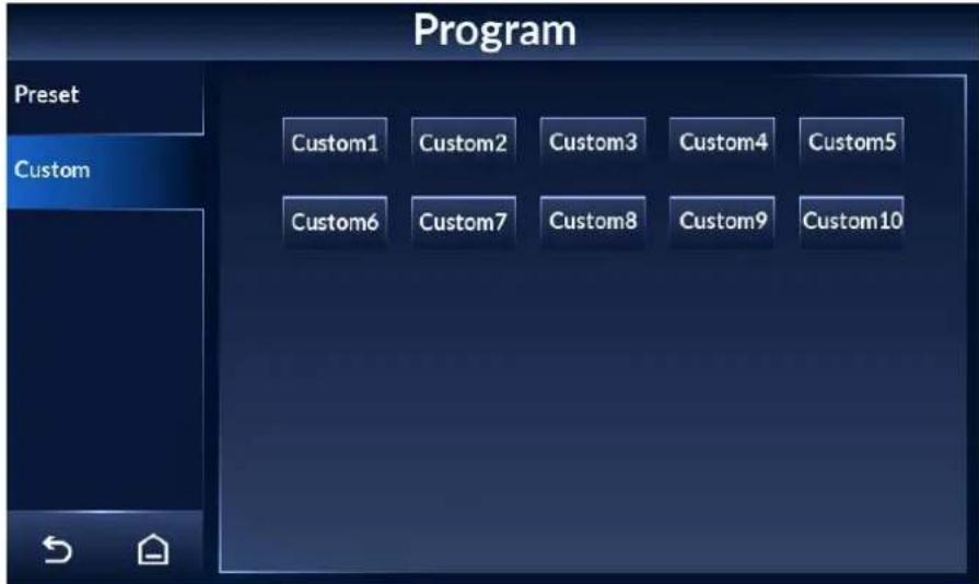
For custom programs, sensitivity of all zones is 255 by default.
Step 1 Tap on the lower-left of the desktop to go to the login screen.
Step 2 Select Program > Custom.
Step 3 Select a custom program.
Ten custom programs are available. You can customize the parameters.
Figure 4-17 Custom programs
4.7 Setting Alarms
4.7.1 Alarm Settings
Step 1 Tap ≡ on the lower-left of the desktop to go to the login screen.
Step 2 Select Alarm >Alarm Setting.
Step 3 Configure alarm settings.
Figure 4-18 Alarm settings
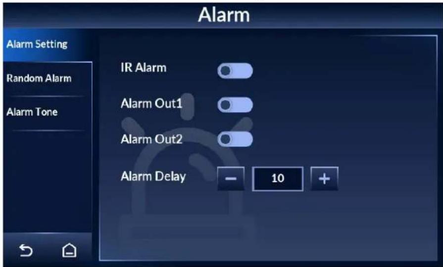
Table 4-3 Alarm setting parameter description
| Item Descriptions | |
| IR Alarm | Tap  to to  ble IR alarm, and tap [2XTY] to disable it. IR status is displayed by [IMAGE] on the bottom of the desktop.After enabling IR alarm, an alarm will be triggered only when a person passing through the Detector with forbidden metal objects are detected by the IR sensors. ble IR alarm, and tap [2XTY] to disable it. IR status is displayed by [IMAGE] on the bottom of the desktop.After enabling IR alarm, an alarm will be triggered only when a person passing through the Detector with forbidden metal objects are detected by the IR sensors. |
| Alarm Out1 | There are two ports on the motherboard that can connect to alarm devices such as light and audio alarms.: Normally open, with the alarm off (default).: Normally closed, with the alarm on. |
| Alarm Out2 | |
| Alarm Delay | Tap + or - to adjust the duration of sound and light alarm. The value ranges from 0 to 10 seconds. Zero means no alarm. |
4.7.2 Random Alarm
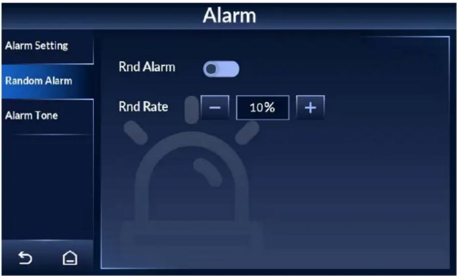
Random alarm is to validate whether the Detector is working.
Step 1 Tap ≡ on the lower-left of the desktop to go to the login screen.
Step 2 Select Alarm > Random Alarm.
Step 3 Tap to enable random alarm and tap to disable it.
Step 4 Set random alarm rate, which ranges from 1% to 100%.
This feature provides the ability to randomly trigger alarm on a selected percentage of non-alarming persons.
Figure 4-19 Random alarm
4.7.3 Alarm Tone and Volume
Step 1 Tap ≡ on the lower-left of the desktop to go to the login screen.
Step 2 Select Alarm >Alarm Tone.
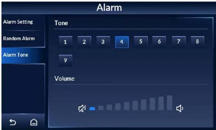
Step 3 Select an alarm tone, and then adjust the volume.
- Nine tones are available. Tone 1 is selected by default. The system plays the tone after it is selected.
- Tap to turn up the volume and tap to turn down the volume.
Figure 4-20 Alarm tone and volume
4.8 Setting IR Mode
Step 1 Tap on the lower-left of the desktop to go to the login screen.
Step 2 Select IR > IR Mode.
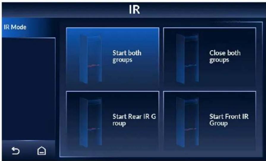
Step 3 Select an IR alarm mode.
Four modes are available.
- Start both groups: The counter adds one pass when both groups of IR sensors are triggered. In this mode, the IR alarm will be automatically turned on.
- Close both groups: The IR alarm will be automatically turned off.
- Start rear IR group: The counter adds one pass when the rear IR group is triggered.
- Start front IR group: The counter adds one pass when the front IR group is triggered.
Figure 4-21 Set IR mode
4.9 Setting Counter
The counter records the number of people who pass through the Detector.
4.9.1 Viewing Counter Data
Procedure
Step 1 Tap ≡ on the lower-left of the desktop to go to the login screen.
Step 2 Select Counter > Counter.
Step 3 View the number of people who pass through the Detector.
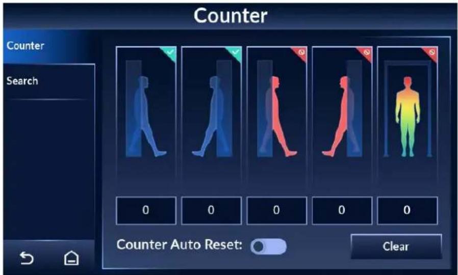
From left to right, the numbers stand for the number of entries (from front to rear), the number of exits (from rear to front), the number of alarms on entry, the number of alarms on exit, and the number of temperature alarms.

The side with the LCD is the rear side.
Figure 4-22 Counter
Related Operations
- Tap to enable the automatic reset function of the counter.
After it is enabled, the numbers will be cleared automatically when the limit (999999) is reached.
- Tap Clear to manually clear all data.
4.9.2 Searching for Count Data
Step 1 Tap ≡ on the lower-left of the desktop to go to the login screen.
Step 2 Select Counter > Search.
Step 3 Set the start time and end time. You can search for data from up to 30 days.
Tap to switch the search unit (hour/day).
Figure 4-23 Search
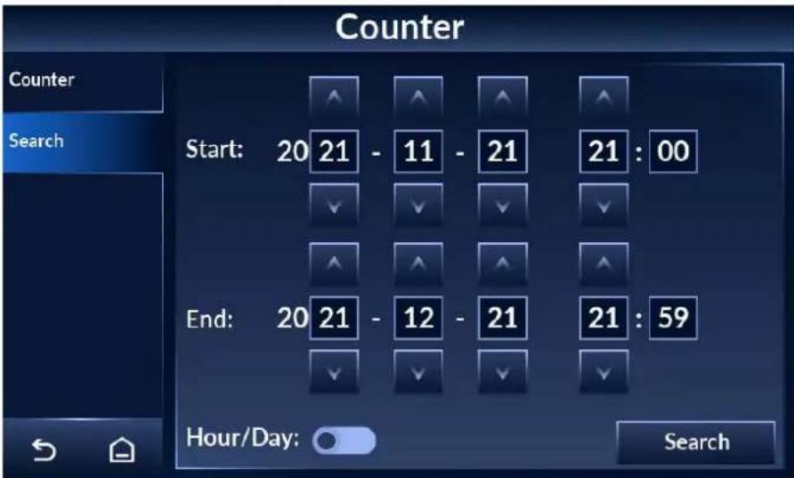
Step 4 Tap Search, and the data will be displayed.
4.10 System Settings
You can set the IP address, password, desktop, date and time, and more. To change the password, see "4.1.2 Changing Password".
4.10.1 Setting Network
Step 1 Tap ≡ on the lower-left of the desktop to go to the login screen.
Step 2 Select System > Network.
Step 3 Enter the IP address (192.168.1.108 by default), subnet mask, and gateway.
Figure 4-24 Set network
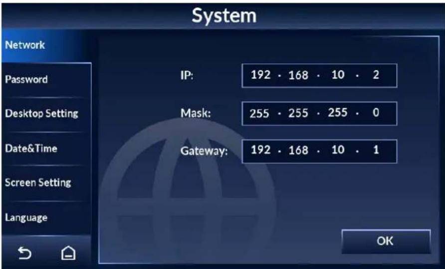
Step 4 Tap OK.
4.10.2 Setting Desktop
You can set the display mode of the desktop, and the counting method of the Detector.
Step 1 Tap ≡ on the lower-left of the desktop to go to the login screen.
Step 2 Select System > Desktop Setting.
Step 3 Tap Metal Alarm Desktop or Temp Alarm Desktop to switch desktop.
For desktop description, see "4.3 Desktop".
Figure 4-25 Metal alarm desktop
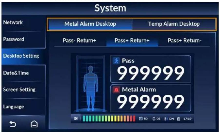
Tap to switch between Celsius degrees and Fahrenheit.
Figure 4-26 Temperature alarm desktop
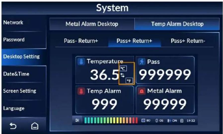
Step 4 Select a counting method from Pass- Return+, Pass+ Return+, and Pass+ Return-.

The side with the LCD is the rear side.
- Pass- Return+: Counts people passing in the reverse direction only and subtracts from the count for people passing in the forward direction.
- Pass+ Return+: Counts people passing in both directions.
- Pass+ Return-: Counts people passing in the normal forward direction only and subtracts from the count for people passing in the reverse direction.
4.10.3 Setting Time
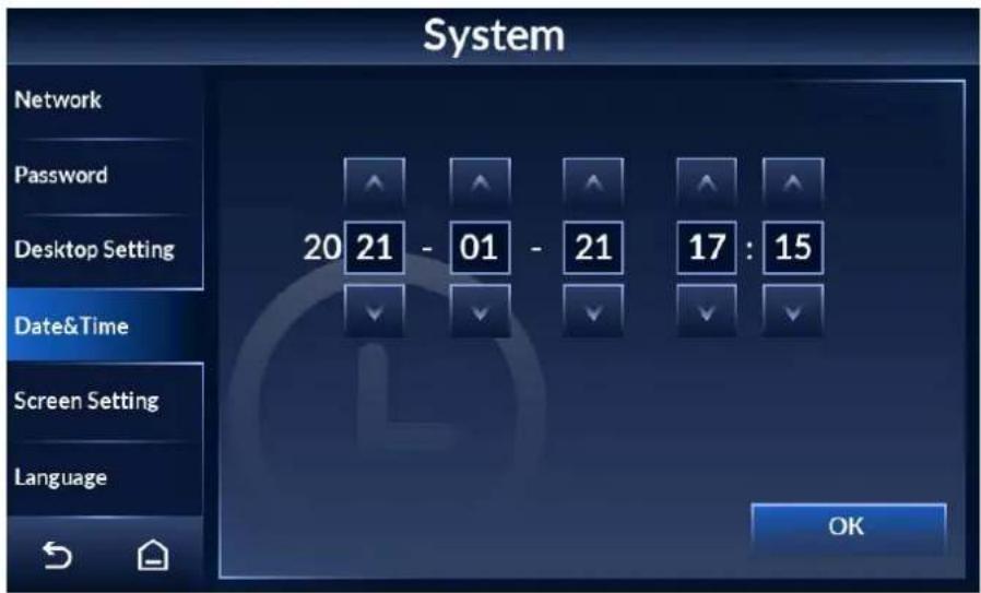
Step 1 Tap ≡ on the lower-left of the desktop to go to the login screen.
Step 2 Select System > Date&Time.
Step 3 Tap or to adjust the date and time.
Step 4 Tap OK.
Figure 4-27 Set date and time.
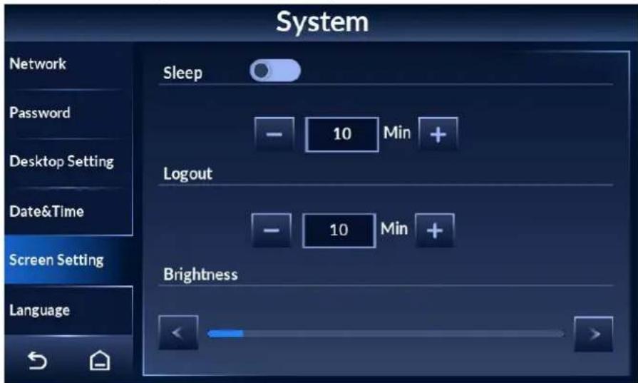
4.10.4 Setting Screen Parameters
Step 1 Tap ≡ on the lower-left of the desktop to go to the login screen.
Step 2 Tap System > Screen Setting.
Step 3 Set the parameters.
- Sleep: Tap ☐ to enable the sleep mode and tap ☐ to disable it. Tap + or - to adjust the sleep time. In the sleep mode, if there is no operation for longer than the sleep time, the brightness of the screen will be reduced. If the brightness is less than a half of the maximum, it will remain the same.
- Logout: Tap + or - to adjust the automatic logout time. If there is no operation for longer than the logout time, the system will go back to the desktop.
- Tap < or > to adjust screen brightness.
Figure 4-28 Set screen parameters
4.10.5 Setting Language
Step 1 Tap ≡ on the lower-left of the desktop to go to the login screen.
Step 2 Select System > Language.
English, Russian, Indonesian, and Turkish are available.
4.11 Maintenance
You can perform IR diagnosis, reset factory settings, start system self-inspection, and view the version.
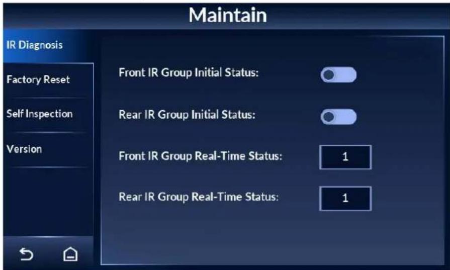
4.11.1 IR Diagnosis
Step 1 Tap ≡ on the lower-left of the desktop to go to the login screen.
Step 2 Select Maintain > IR Diagnosis.
Step 3 Set front/rear IR group initial status, and view front/rear IR group real-time status.
- Tap 📄, and the IR will be on when the Detector is powered on. Tap 📄 and the IR will be off when the Detector is powered on.
- Real-time status: 1 means there is no block between the IR sensors. 0 means there is block between the IR sensors.
Figure 4-29 IR diagnosis
4.11.2 Factory Reset
Step 1 Tap ≡ on the lower-left of the desktop to go to the login screen.
Step 2 Select Maintain > Factory Reset.
Step 3 Tap Factory Reset, and the system prompts Restore factory and reboot?
Step 4 Tap OK, and the Detector restarts.
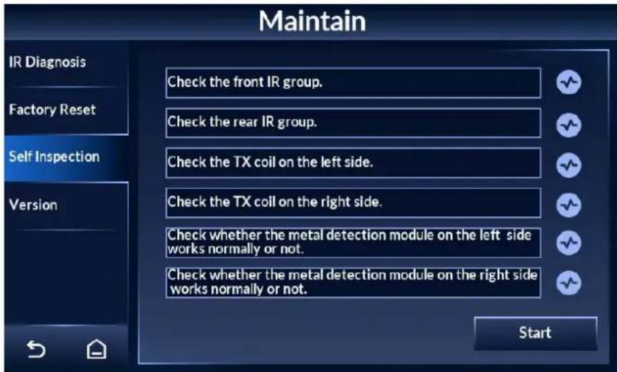
4.11.3 Self Inspection
Step 1 Tap 📋 on the lower-left of the desktop to go to the login screen.
Step 2 Select Maintain > Self Inspection.
Step 3 Tap Start, and the system checks the items one by one.

During self inspection, all the other operations on the Detector are invalid.
Figure 4-30 Self inspection
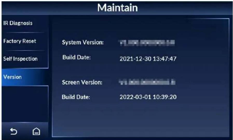
4.11.4 Viewing Version
You can view the system version, the screen version, and their build dates.
Step 1 Tap ≡ on the lower-left of the desktop to go to the login screen.
Step 2 Select Maintain > Version to view system version and screen version.

The version might be different depending on the model you purchased.
Figure 4-31 View version details
5 Camera Configuration
With a thermal camera, the Detector supports temperature monitoring. The detection rules are configured by default, and you can change the configuration as needed. For details, see Thermal Hybrid Camera_Web Operation Manual.
5.1 Logging in to Camera Web
Step 1 Open IE browser (IE7 and later), enter the IP address of the device (192.168.1.108 by default) in the address bar and press the Enter key.
Step 2 Enter the username (admin by default) and password.
Step 3 Click Login.
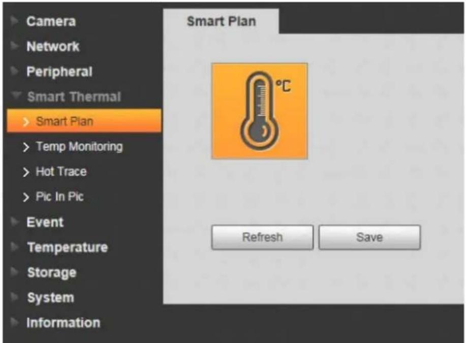
5.2 Enabling Smart Plan
Step 1 Log in to the web page of the camera.
Step 2 Select Setting > Event > Smart Plan.
Step 3 Enable thermal temperature monitoring.
Click 📄 to enable it, and the icon is highlighted.
Figure 5-1 Smart Plan
5.3 Configuring Temperature Monitoring
Thermal temperature monitoring is enabled. For details, see "5.2 Enabling Smart Plan".
Step 1 Log in to the web page of the camera.
Step 2 Select Setting > Smart Thermal > Temp Monitoring.
Step 3 Click Draw Rule to draw a detection area.
Confirm that the lower border of the detection area is near people shoulders and upper border can be the upper edge of the thermal image.
Step 4 Select the Enable check box. It is selected by default.
Configure thermal temperature monitoring parameters.
Figure 5-2 Temperature monitoring
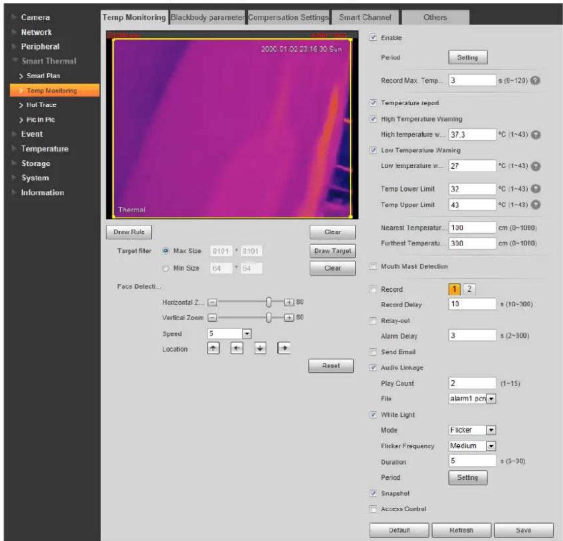
Step 5 Configure thermal temperature monitoring parameters.
Table 5-1 Description of temperature monitoring parameter
| Parameter Description | |
| Period | Define a period during which the alarm settings are valid.1.ClickSetting, and the period setting page is displayed.2.Configure period.Method 1: Press and drag the left mouse button on the time line.Method 2: ClickSettingcorresponds to a day in a week, and then configure periods as needed (6 periods are available).3.ClickSave. |
| Parameter Description | |
| Record Max.Temperature | Set the period during which the camera will monitor the temperature, and capture the image when the temperature reaches the highest value. It is 3 s by default. When the value is 0, it means that the camera will capture the image when the target appears in the detection area. |
| TemperatureReport | Enable temperature report, and the temperature is displayed on the screen of the Detector in real time. |
| High TemperatureWarning | Enable the high temperature warning, and then set the warning threshold. It ranges from 1 °C to 43 °C (37.3 °C by default). When the monitored temperature is higher than or equal to this value, an alarm is triggered. |
| Low TemperatureWarning | Enable the low temperature warning, and then set the warning threshold. It ranges from 1 °C to 43 °C (27 °C by default). When the monitored temperature is lower than or equal to this value, an alarm is triggered. |
| Temp Lower Limit | Set the lower limit of the body temperature. The camera only monitors temperature that is higher than or equal to this value. It is 43 °C by default. |
| Temp Upper Limit | Set the upper limit of the body temperature. The camera only monitors temperature that is lower than or equal to this value. It is 32 °C by default. |
| NearestTemperatureDistance | The camera detects the target between the nearest temperature distance and furthest temperature distance. It takes effect after the distance detection is enabled. The nearest temperature distance is 50 cm, and the furthest temperature is 200 cm by default. |
| FurthestTemperatureDistance | SelectSetting > Smart Thermal > Smart Channel to enable distance detection. |
5.4 Configuring Smart Channel
Step 1 Log in to the web page of the camera.
Step 2 Select Setting > Smart Thermal > Smart Channel.
Figure 5-3 Temperature monitoring
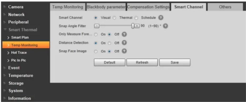
Step 3 Select the display mode of the channel.
- Visual: It is selected by default.
- Thermal: When the light is not good (such as black light, and the light is not enough), we recommend you select Thermal.
- Schedule: Select Schedule and then configure the schedule. The two channels will switch automatically as the configured schedule.
Step 4 (Optional) Configure Snap Angle Filter.
- 1: The camera detects frontal faces only.
- 90 (default): The camera detects side faces only.

Snap angle filter is only supported when you select Visual from the display mode of smart channel.
Step 5 Enable Only Measure Forehead as needed.
After enabling this function, the camera only detects the temperature of the forehead area. It can reduce the false alarm caused by the high temperature of background.
Step 6 Enable Distance Detection as needed.
It is enabled by default.
Step 7 Enable Snap Face Image as needed.
Step 8 Click OK.
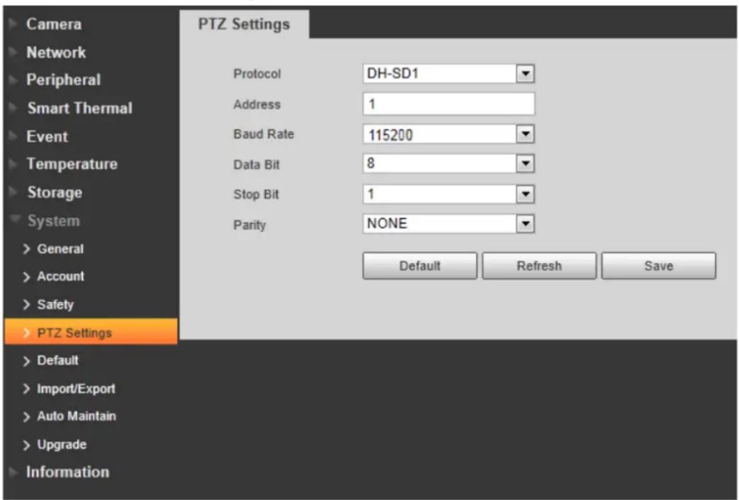
5.5 Setting Baud Rate
Step 1 Log in to the web page of the camera.
Step 2 Select Setting > System > PTZ Setting.
Step 3 Set the baud rate. It is 115200 by default.
You need to set it to 115200, so that temperature data can be transmitted to the Detector. Keep other parameters as default.
Step 4 Click OK.
Figure 5-4 Set baud rate
6 Upgrading Detector
You can use ConfigTool to upgrade the Detector software.

Go to
https://www.dahuasecurity.com/support/downloadCenter/tools/MaintenanceTools?child=332 to download ToolBox, and then install ConfigTool.
6.1 Configuring Network
Before upgrading the Detector, you need to connect your computer and the Detector to the same local network first.
Step 1 Connect a network cable to the network port of the door panel, so that the Detector and your computer are in the same LAN.
Step 2 Set the IP of the Detector and the computer on the same network segment. For example, if the IP of the Detector is 192.168.1.108 by default, you can set the IP of the computer as 192.168.1.111.
Step 3 Open ConfigTool, and then select Modify IP > Search Setting.
Step 4 Enter the network segment of the Detector in the Start IP box and End IP box.
Step 5 Enter the username and password of the Detector. The password is the same as the login password of the admin account.
Figure 6-1 Search for the Detector on ConfigTool
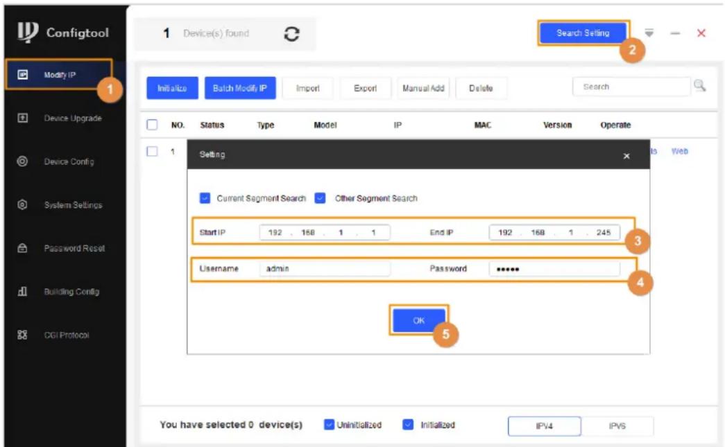
Step 6 Click OK.
6.2 Viewing Current Version
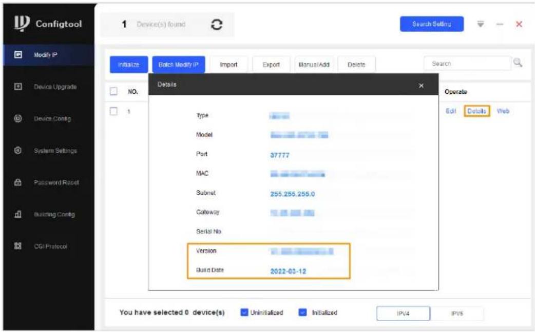
Click Details to view the current software version of the Detector.
Figure 6-2 View current version
6.3 Upgrading Detector
Select the bin file to upgrade the Detector.
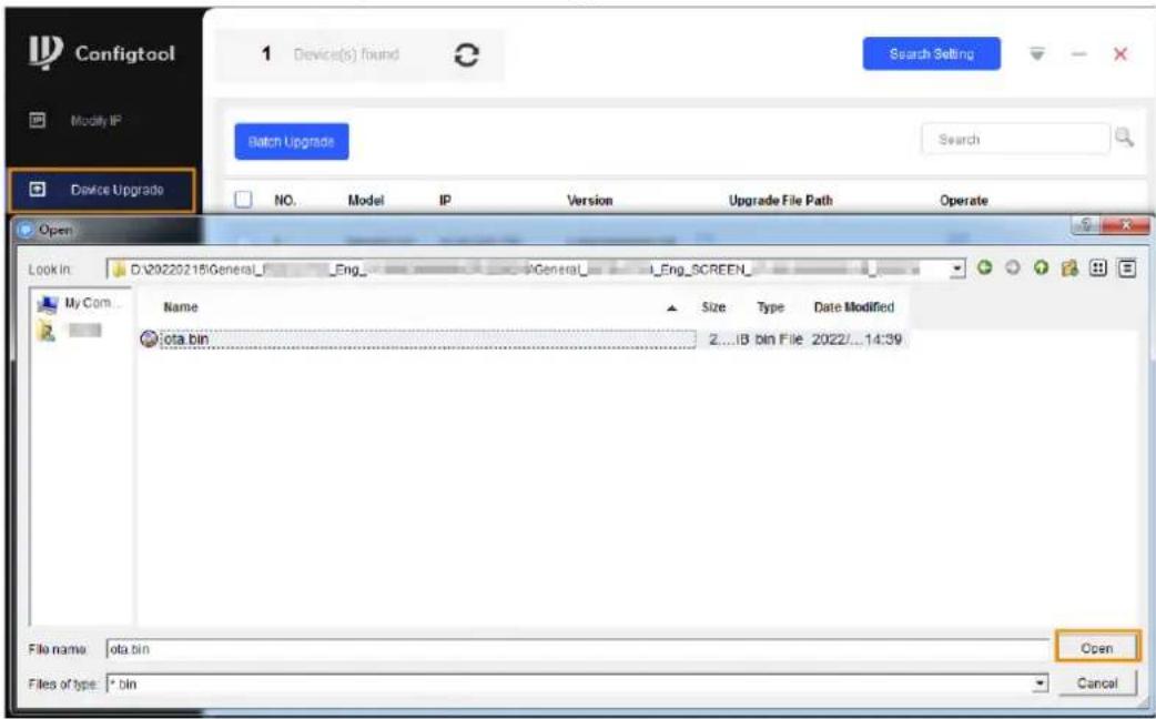
- Click Device Upgrade.
- Upgrade the program.
- Upgrade the screen program.
Click, select the ota.bin file from the General_ISC-
D7xx_Eng_SCREEN_V1.000.000000.0R_xxxxxx directory, and then click Open.
Figure 6-3 Select upgrade file
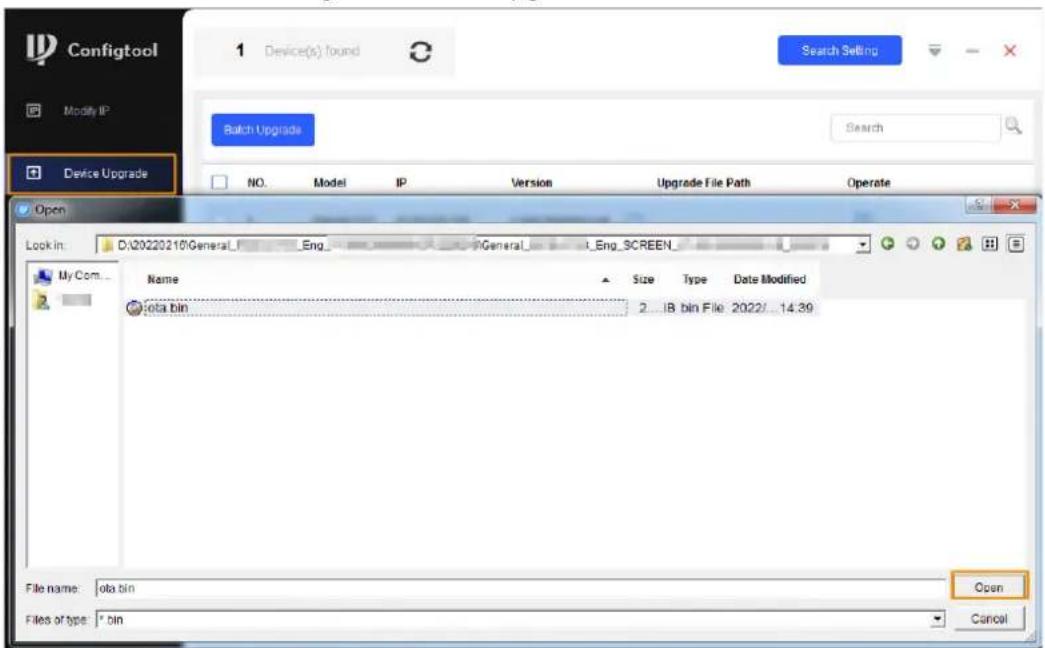
- Upgrade the main control module program.
Click ☐, select the General_ISC-D7xx_Eng_App_MCU_V1.000.0000000.0.R.xxxxxx.bin file from the General_ISCD-D7xx_Eng_MCU_V1.000.0000000.0.R_xxxxxx directory, and then click Open.
Figure 6-4 Select upgrade file
- Click ↑ to start upgrading.
After upgrade is complete, a notice dialog box will be displayed indicating the Detector will be restarted. Then the Detector restarts automatically.
- A green tick is displayed after the upgrade is successful.
Figure 6-5 Upgrade completed

- If you need to reset the Detector to factory default, see "4.11.2 Factory Reset", and then configure parameters.
7 FAQ
1. Deal with the replaced spare parts.
Contact our overseas maintenance points to check whether you need to send back the spare parts.
2. The Detector cannot start.
a. Check whether the power is switched on.
b. Check whether the power cable is loose or broken.
c. Replace the host box.
3. The screen cannot display content after the Detector starts.
a. Check whether the power is switched on.
b. Check whether the cable between the door panel and the host box is properly connected.
c. Check whether the cables in the host box are properly connected, and whether ribbon cables and probes are loose or broken.
d. Replace the host box.
4. The passed people cannot be counted. (The indicator light cannot work normally, or the Detector might alarm without people passing.)
a. Check whether the infrared start-stop mode is Start both groups; if not, select the mode to Start both groups.
b. Enable Start former group or Start latter group separately to check which group cannot work normally.
c. Check the problematic group through a camera of a phone with Android OS. Make the camera to the transmitting terminal (two ports) to check whether there is a red dot in the image. If there is no red dot in the image, the infrared sensor on the transmitting terminal cannot work normally, and you need to replace it.
d. Remove the host and test it with the door panels that can work normally. If the problem still cannot be solved, replace the host box; otherwise, replace the door panel.
5. There are false alarms.
a. Check whether the environment influences the detection rate of the Detector. For example, check whether there is direct light to the infrared sensors, and whether there are large metals within 1 meter's range.
b. Adjust the frequency. To set the suitable frequency quickly, we recommend 3 levels for an adjustment. For example, when the current frequency is 3, adjust it to 6, and then check whether there are false alarms; if yes, adjust it to 9, and then check whether there are false alarms again. Repeat the operation until there is no false alarm..
c. Adjust the security level lower.
d. Replace the host detector for testing.
e. If the problem still cannot be solved, replace the door panels.
6. An alarm is not triggered when carry-on metal is passing.
a. Adjust the sensitivity of each zone higher.
b. If the alarm is not triggered with the highest sensitivity, replace the host detector for testing.
c. If the problem still cannot be solved, replace door panels.
7. Alarm lights are not on.
a. Check whether the power supplies of host and door panel are normal.
b. Check whether the ribbon cables of the alarm light are loose or broken.
c. If the problem still cannot be solved, replace the host detector.
8. No alarm is triggered in zones.
a. Adjust the sensitivity value higher
b. Replace the host detector.
c. If the problem still cannot be solved, replace door panels.
9. No alarm sound.
a. Check whether the alarm sound is disabled.
b. Replace the speaker.
10. There are big differences among the zone sensitivity values.
a. Configure the sensitivity values according to the actual situation of each zone.
b. If the problem still cannot be solved, replace door panels.
11. Buttons on the host box cannot work normally.
a. Check whether buttons are in good contact.
b. If buttons are in good contact, replace the mainboard.
12. The count result cannot be displayed.
a. Check whether ribbon cables and probes of the display screen are loose or broken.
b. If the problem still cannot be solved, replace the host.
13. The port cannot work normally.
a. Check whether port cables are loose or broken.
b. Install the mainboard program again.
c. If the problem still cannot be solved, replace the related accessories.
14. The network of host box is not connected successfully.
a. Check whether the network cable is connected well, and whether the Detector IP and the default IP are in the same network segment.
b. Check whether the connection board and cable are connected well, or whether they are broken.
c. Install the mainboard program again.
d. If the problem still cannot be solved, replace the related accessories.
15. The network of the thermal camera is not connected successfully.
a. Check whether the network cable is connected well, and whether the Detector IP and the default IP are in the same network segment.
b. Check whether the connection board and cable are connected well, or whether they are broken.
c. Check whether the network indicator is on; if not, check whether the network cable is good, or whether the camera is power on.
d. If the problem still cannot be solved, replace the camera.
16. The detected temperature cannot be displayed normally.
a. Check the camera mount angle, and adjust it as needed.
b. Check whether the camera is connected to the Detector successfully.
c. Check whether the port cable is connected well, or whether it is broken.
d. Change the positions of the two terminals of the 485 cable.
e. Install the mainboard program again.
f. If the problem still cannot be solved, replace the camera.
17. The temperature on the front forehead is recommended.
The forehead temperatures of different people are different. With face mask covering the face, it is easy for the camera to monitor the forehead temperature; the highest temperature points are on the forehead, ears and neck, and the actual situation might vary according to different people. Make the camera monitor forehead temperature to reduce the influence from the temperature differences of different parts.
- The recommended temperature conditions for temperature monitoring.
Indoor windless environment with the ambient temperature 10 °C to 30 °C.
- Temperature monitoring and face detection function cannot work normally after correct configuration.
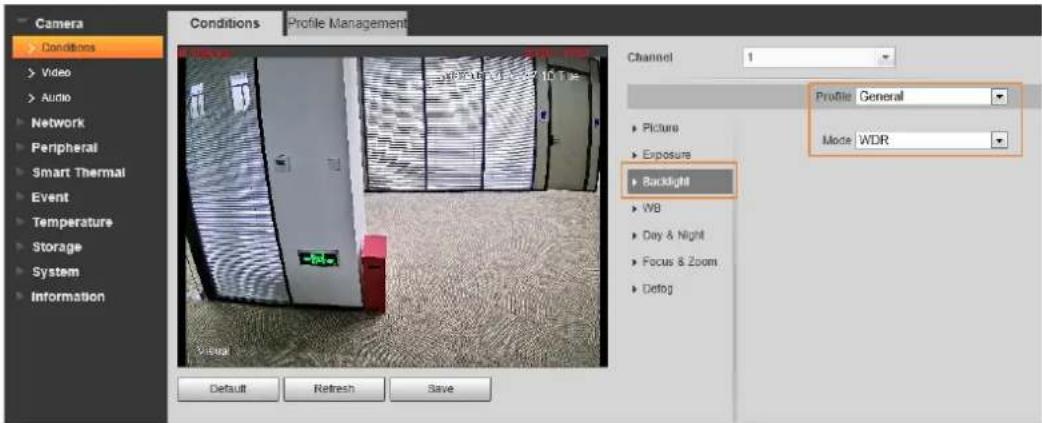
a. The camera detects face with the visual channel by default. Check whether the problem is caused by back light, or weak light; if yes, enable WDR in visual channel or select thermal channel to monitor temperature.
b. The camera has no license. Apply for the license.
- There is missing detection for temperature monitoring.
a. Faces cannot be detected in backlight or low illumination environment, so the temperature cannot be monitored. Enable WDR in backlight environment.
b. Face filter angle is configured to small, and the camera cannot capture the face except front faces.
c. Faces covered by helmets, hats or hands cannot be detected.
Figure 7-1 Enable WDR
- The bottom of the desktop displays

a. No SLA battery is connected.
b. No UPS board is connected or the UPS board is broken.
Appendix 1 Cybersecurity Recommendations
Mandatory actions to be taken for basic device network security:
1. Use Strong Passwords
Please refer to the following suggestions to set passwords:
- The length should not be less than 8 characters.
- Include at least two types of characters; character types include upper and lower case letters, numbers and symbols.
- Do not contain the account name or the account name in reverse order.
- Do not use continuous characters, such as 123, abc, etc.
- Do not use overlapped characters, such as 111, aaa, etc.
2. Update Firmware and Client Software in Time
- According to the standard procedure in Tech-industry, we recommend to keep your device (such as NVR, DVR, IP camera, etc.) firmware up-to-date to ensure the system is equipped with the latest security patches and fixes. When the device is connected to the public network, it is recommended to enable the auto-check for updates function to obtain timely information of firmware updates released by the manufacturer.
- We suggest that you download and use the latest version of client software.
"Nice to have" recommendations to improve your device network security:
1. Physical Protection
We suggest that you perform physical protection to device, especially storage devices. For example, place the device in a special computer room and cabinet, and implement well-done access control permission and key management to prevent unauthorized personnel from carrying out physical contacts such as damaging hardware, unauthorized connection of removable device (such as USB flash disk, serial port), etc.
2. Change Passwords Regularly
We suggest that you change passwords regularly to reduce the risk of being guessed or cracked.
3. Set and Update Passwords Reset Information Timely
The device supports password reset function. Please set up related information for password reset in time, including the end user's mailbox and password protection questions. If the information changes, please modify it in time. When setting password protection questions, it is suggested not to use those that can be easily guessed.
4. Enable Account Lock
The account lock feature is enabled by default, and we recommend you to keep it on to guarantee the account security. If an attacker attempts to log in with the wrong password several times, the corresponding account and the source IP address will be locked.
5. Change Default HTTP and Other Service Ports
We suggest you to change default HTTP and other service ports into any set of numbers between 1024–65535, reducing the risk of outsiders being able to guess which ports you are using.
6. Enable HTTPS
We suggest you to enable HTTPS, so that you visit Web service through a secure communication channel.
7. MAC Address Binding
We recommend you to bind the IP and MAC address of the gateway to the device, thus reducing the risk of ARP spoofing.
8. Assign Accounts and Privileges Reasonably
According to business and management requirements, reasonably add users and assign a minimum set of permissions to them.
9. Disable Unnecessary Services and Choose Secure Modes
If not needed, it is recommended to turn off some services such as SNMP, SMTP, UPnP, etc., to reduce risks.
If necessary, it is highly recommended that you use safe modes, including but not limited to the following services:
- SNMP: Choose SNMP v3, and set up strong encryption passwords and authentication passwords.
- SMTP: Choose TLS to access mailbox server.
- FTP: Choose SFTP, and set up strong passwords.
- AP hotspot: Choose WPA2-PSK encryption mode, and set up strong passwords.
10. Audio and Video Encrypted Transmission
If your audio and video data contents are very important or sensitive, we recommend that you use encrypted transmission function, to reduce the risk of audio and video data being stolen during transmission.
Reminder: encrypted transmission will cause some loss in transmission efficiency.
11. Secure Auditing
- Check online users: we suggest that you check online users regularly to see if the device is logged in without authorization.
- Check device log: By viewing the logs, you can know the IP addresses that were used to log in to your devices and their key operations.
12. Network Log
Due to the limited storage capacity of the device, the stored log is limited. If you need to save the log for a long time, it is recommended that you enable the network log function to ensure that the critical logs are synchronized to the network log server for tracing.
13. Construct a Safe Network Environment
In order to better ensure the safety of device and reduce potential cyber risks, we recommend:
- Disable the port mapping function of the router to avoid direct access to the intranet devices from external network.
- The network should be partitioned and isolated according to the actual network needs. If there are no communication requirements between two sub networks, it is suggested to use VLAN, network GAP and other technologies to partition the network, so as to achieve the network isolation effect.
- Establish the 802.1x access authentication system to reduce the risk of unauthorized access to private networks.
- Enable IP/MAC address filtering function to limit the range of hosts allowed to access the device.
- Walk-through Metal Detector
- Foreword
- General
- Safety Instructions
- Revision History
- Privacy Protection Notice
- Interface Declaration
- About the Manual
- Important Safeguards and Warnings
- Transportation Requirements
- Storage Requirements
- Installation Requirements
- Operation Requirements
- Maintenance Requirements
- WARNING
- Table of Contents
- Foreword....
- Important Safeguards and Warnings....III
- Overview....1
- Structure 2
- Installation....8
- Configuration....14
- Setting Frequency....20
- Setting Program 22
- Setting Alarms....26
- Setting IR Mode 28
- Setting Counter 29
- System Settings 30
- Maintenance....33
- Camera Configuration ....36
- Upgrading Detector 40
- FAQ 44
- Appendix 1 Cybersecurity Recommendations....47
- Overview
- Introduction
- Technical Advantages
- Structure
- Dimensions
- Host Box
- Ports
- UPS
- Function of the UPS Board
- Battery Requirements
- Battery Charging Time
- SLA Battery Life
- Installation
- Checklist
- Environmental Requirements
- Installing Detector
- Installing Thermal Camera
- Multiple Walk-through Site Installation
- Configuration
- Login and Changing Password
- Login
- First-time Login
- Not First Time Login
- Changing Password
- Operation Access
- Desktop
- Setting Sensitivity
- Setting Sensitivity Manually
- Procedure
- Setting Sensitivity Automatically
- Setting Security Level
- Setting Frequency
- Setting Frequency Manually
- Step 3
- Setting Frequency Automatically
- Step 1
- Step 2 Select
- Step 3 Tap
- Step 4 Tap
- Setting Extended Frequency
- Setting Program
- Preset Programs
- Custom Programs
- Setting Alarms
- Alarm Settings
- Random Alarm
- Alarm Tone and Volume
- Setting IR Mode
- Setting Counter
- Viewing Counter Data
- Related Operations
- Searching for Count Data
- System Settings
- Setting Network
- Setting Desktop
- Setting Time
- Setting Screen Parameters
- Setting Language
- Maintenance
- IR Diagnosis
- Factory Reset
- Self Inspection
- Viewing Version
- Camera Configuration
- Logging in to Camera Web
- Enabling Smart Plan
- Configuring Temperature Monitoring
- Configuring Smart Channel
- Step 4 (Optional) Configure Snap Angle Filter.
- Step 5 Enable Only Measure Forehead as needed.
- Step 6 Enable Distance Detection as needed.
- Step 7 Enable Snap Face Image as needed.
- Setting Baud Rate
- Step 2 Select Setting > System > PTZ Setting.
- Upgrading Detector
- Configuring Network
- Viewing Current Version
- Upgrading Detector
- FAQ
- Deal with the replaced spare parts.
- The Detector cannot start.
- The screen cannot display content after the Detector starts.
- The passed people cannot be counted. (The indicator light cannot work normally, or the Detector might alarm without people passing.)
- There are false alarms.
- An alarm is not triggered when carry-on metal is passing.
- Alarm lights are not on.
- No alarm is triggered in zones.
- No alarm sound.
- There are big differences among the zone sensitivity values.
- Buttons on the host box cannot work normally.
- The count result cannot be displayed.
- The port cannot work normally.
- The network of host box is not connected successfully.
- The network of the thermal camera is not connected successfully.
- The detected temperature cannot be displayed normally.
- The temperature on the front forehead is recommended.
- Appendix 1 Cybersecurity Recommendations
- Mandatory actions to be taken for basic device network security:
- Use Strong Passwords
- Update Firmware and Client Software in Time
- "Nice to have" recommendations to improve your device network security:
- Physical Protection
- Change Passwords Regularly
- Set and Update Passwords Reset Information Timely
- Enable Account Lock
- Change Default HTTP and Other Service Ports
- Enable HTTPS
- MAC Address Binding
- Assign Accounts and Privileges Reasonably
- Disable Unnecessary Services and Choose Secure Modes
- Audio and Video Encrypted Transmission
- Secure Auditing
- Network Log
- Construct a Safe Network Environment
Brand : Dahua Technology
Model : ISC-D733-TS2
Category : Detector