T 260 - Tachometer PCE Instruments - Free user manual and instructions
Find the device manual for free T 260 PCE Instruments in PDF.


| Product Type | Digital Tachometer |
| Brand | PCE Instruments |
| Model | T 260 |
| Measurement Method | Contact (with adapter) and Non-Contact (optical) |
| Measuring Range (RPM) | 2.5 to 99,999 RPM (contact); 2.5 to 99,999 RPM (non-contact) |
| Accuracy | ±0.05% of reading + 1 digit |
| Resolution | 0.1 RPM (2.5–999.9 RPM); 1 RPM (>1000 RPM) |
| Display | 5-digit LCD with backlight |
| Power Supply | 2 x 1.5V AAA batteries (included) |
| Battery Life | Approx. 40 hours continuous |
| Auto Power Off | Yes, after 5 minutes of inactivity |
| Memory Functions | Last, max, min, and average value recall |
| Dimensions | Approx. 150 x 60 x 30 mm (5.9 x 2.4 x 1.2 in) |
| Weight | Approx. 110 g (3.9 oz) with batteries |
| Operating Temperature | 0°C to 50°C (32°F to 122°F) |
| Storage Temperature | −10°C to 60°C (14°F to 140°F) |
| Maintenance & Cleaning | Wipe with a dry, soft cloth. Avoid solvents or abrasives. |
| Safety Precautions | Do not use near flammable materials. Keep away from moving parts when measuring. |
| Spare Parts / Repairability | Contact PCE Instruments for replacement parts or service. Not user-serviceable. |
| Included Accessories | Contact adapter (cone & cup), reflective tape, carrying case, batteries, manual |
| General Information | Suitable for measuring rotational speed of motors, shafts, fans, and belts. |
Frequently Asked Questions - T 260 PCE Instruments
User questions about T 260 PCE Instruments
0 question about this device. Answer the ones you know or ask your own.
Ask a new question about this device
Download the instructions for your Tachometer in PDF format for free! Find your manual T 260 - PCE Instruments and take your electronic device back in hand. On this page are published all the documents necessary for the use of your device. T 260 by PCE Instruments.
USER MANUAL T 260 PCE Instruments
+ Type k Temp., Pt 1000 ohm Temp. IR Temp.
AUTOMOTIVE TESTER
Model : PCE-T 260
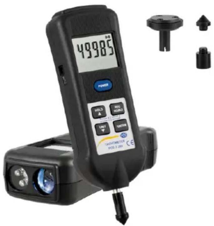

www.pce-instruments.com/english
www.pce-instruments.com
Your purchase of this TACHOMETER/STROBOSCOPE Meter marks a step forward for you into the field of precision measurement. Although this METER is a complex and delicate instrument, its durable structure will allow many years of use if proper operating techniques are developed. Please read the following instructions carefully and always keep this manual within easy reach.
PCE Instruments UK Ltd.
Units 12/13
Southpoint Business Park
Ensign way
Hampshire / Southampton
United Kingdom, SO31 4RF
From outside UK: +44
Tel: (0) 2380 98703 0
Fax: (0) 2380 98703 9
info@industrial-needs.com
TABLE OF CONTENTS
-
FEATURES.... 1
-
SPECIFICATIONS.... 2
-
FRONT PANEL DESCRIPTION.... 6
3-1 Display 6
3-2 Power button.... 6
3-3 HOLD/▲ button.... 6
3-4 REC/DOUBLE button.... 6
3-5 UNIT/▼ button.... 6
3-6 Function button.... 6
3-7 RPM Adapter.... 6
3-8 Surface Speed Test Wheel.... 6
3-9 Funnel type rubber for RPM adapter.... 6
3-10 RS-232 Output Terminal.... 6
3-11 Pt 1000Ω probe Terminal.... 6
3-12 Thermocouple(type k) probe Terminal.... 6
3-13 IR Thermometer.... 6
3-14 Battery Compartment/Cover 6
3-15 Reflecting Mark.... 6
3-16 Photo led light beam.... 6
3-17 Stroboscope flash light (red) indicator.... 6
3-18 Monitor indicator.... 6
3-19 DC 9V adapter socket.... 6
-
PHOTO TACHOMETER MEASURING PROCEDURE.... 7
-
CONTACT TACHOMETER MEASURING PROCEDURE.... 8
-
STROBOSCOPE OPERATION PROCEDURE.... 9
-
Type K Thermometer MEASURING PROCEDURE.... 10
-
RTD Temperature MEASURING PROCEDURE.... 11
-
Infrared Thermometer MEASURING PROCEDURE.... 11
-
RECORD OPERATION PROCEDURE.... 12
-
ADVANCED SETTING 13
-
BATTERY REPLACEMENT.... 14
-
RS232 PC SERIAL INTERFACE.... 14
1. FEATURES
* Multi-functions, one instrument combine Photo Tachometer (RPM) & Contact Tachometer (RPM, m/min., ft/min., in/min.). Stroboscope, Type K Thermometer, Pt 1000 Thermometer, IR Thermometer.
* High intensity white light beam for photo tachometer, safety and save the power energy.
* Wide measuring range from 0.5 to 99,999 RPM.
* 0.5 RPM resolution for the measured value < 1000 RPM.
* High precision with 0.05% accuracy.
* The last value, max. value, min. value will be stored into the memory automatically & can be obtained by pressing REC Button.
* Large LCD display
* High visible LCD display gives RPM reading exactly with no guessing or errors & saves battery energy.
* This tachometer used the exclusive one chip MICRO-COMPUTER LSI circuit & crystal time base, offer the high accurate measurement & fast sampling time.
* The use of durable, long lasting components, including a strong, light weight ABS plastic housing, assures almost maintenance free performance for many years.
* The housing cabinet has been carefully shaped to fit comfortable in either hand.
2. SPECIFICATIONS
2-1 General Specifications
| Display | 43 mm x 33 mm LCD, 5 digits.5 digits with display unit. |
| Measurement | 1. Photo Tachometer. 2. Contact Tachometer3. Stroboscope Tachometer. 4. Type K thermometer5. P t 1000 Ω thermometer. 6. IR thermometer |
| Operating Humidity Max. 80% RH. | |
| Operating 0 to 50 °C ( 32 to Temperature | 122 °F ) |
| Over Input Indication of "- - - "Indicater. | |
| Power Supply | UM3-AA X 4 ( DC 6 V battery ),DC Adapter (adapter is optional) |
| Power Consumption | Approx. DC 42 mA |
| Weight | 240g/0.53 LB (Meter only) |
| Dimension | HWD 207 x 67 x 45 mm (8.15 x 2.63 x 1.77 inch). |
| Time base Quartz crystal. | |
| Circuit Exclusive one-chip of microcomputerLSI circuit. | |
| Memory Last/Max./Min. value. | |
| Accessories Hard carrying case ...... 1 PC.Included Reflecting tape marks( 600 mm )...... 1 PC.RPM adapter ( CONE )...... 1 PC.RPM adapter ( FUNNEL )...... 1 PC.Surface speed test wheel...... 1 PC.Operation manual...... 1 PC. | |
Photo Tachometer
| Measurement Photo Tachometer: & Range 5 to 99,999 RPM. | |
| Resolution RPM: | 0.5 RPM (< 1,000 RPM).1 RPM (≥1,000 RPM). |
| Accuracy ±(0.05% reading+ 1 digit). | |
| Photo 50 to 150 mm/2 to 6 inch. (typical Tachometer max. 300 mm/12 inch, depending detecting upon ambient light).distance * Spec. of detecting distance are thatunder the size of reflecting tape is 10 mm square & the measuring RPM value is 1,800 RPM. The max. & min. detecting distance may change under different environment, different reflecting tape or the measuring RPM beyond 1800 RPM. | |
Contact Tachometer
| Measurement Contact & Range 0.5 to 19,999 | Tachometer : RPM. |
| Resolution CONTACT | (RPM):0.5 RPM (< 1000 RPM ).1 RPM ( ≥ 1,000 RPM ).SURFACE SPEED (m/min.):0.05 m/min. (< 100 m/min. ).0.1 m/min. ( ≥ 100 m/min. ).SURFACE SPEED (ft / min.):0.1 ft / min. (< 1,000 ft/min. ).1 ft / min. ( ≥ 1,000 ft/min. ).SURFACE SPEED (in./min.):0.1 in./ min. (< 1000 in./min. ).1 in. /min. ( ≥ 1,000 in./min. ). |
| Accuracy ± ( 0.05% reading+ 1 digit ). | |
NOTE: When using test wheel, accuracy can be affected as much as 0.5% of reading.
Stroboscope Tachometer
| Flash adjust 100 to 999 range * RPM : round per minute. | 990 RPM/FPM. | |
| * FPM : flash per minute. | ||
| Resolution 0.1 RPM : 5 | RPM :< 1,000 RPM. | ≥ 30,000 - 50,000 RPM |
| 1 RPM : 10 RPM :≥ 1,000 - 30000 RPM | ≥ 50,000 - 99,990 RPM | |
| Function Digital rotate buttons x 2 button, ÷ 2 | knob,button,+ button, - button, | |
| Accuracy ±(0.1 % reading+ 2d) | * Spec. tested under the environmentRF Field Strength less than 3 V/M & frequency less than the 30 MHz only. | |
Type K thermometer
| Sensor Resolution Type | Accuracy | ||
| Type K | 0.1 °C | -50.0 to 1300.0 °C-50.1 to -100.0 °C ± (0.4 % reading+ 1 °C) | ± (0.4 % reading+ 0.5 °C) |
| 0.1 °F | -58.0 to 2372.0 °F-58.1 to -148.0 °F ± (0.4 % reading+ 1.8 °F) | ± (0.4 % reading+ 1 °F) | |
P t 1000 Ω thermometer
| Unit Range R | Resolution Accuracy | ||
| °C | -10 to 70 °C | 0.1 °C | ± 1.2 °C reading |
| °F | 14 to 158 °F | 0.1 °F | ± 2.2 °F reading |
IR thermometer
| Emissivity 0.95 fixed value | |
| Spectral response | 6 to 14 μm (wavelength) |
| Field of View D/S | D/S =Approx. 3 : 1 ratio (D = distance, S =spot) |
| Unit Range R | resolution Accuracy | ||
| °C | -30 to 305 °C | 0.5 °C | ± 3 % reading or ± 3 °C |
| °F | -22 to 581 °F | 0.5 °F | ± 3 % reading or ± 5.4 °F |
| Spec. is tested under the 20 cm dia. Black body, the measuring distance between the sensing head and the target is 30 cm. | |||
Spec. tested under the environment RF Field Strength less than 3 V/M & frequency less than the 30 MHz only.
3. FRONT PANEL DESCRIPTION
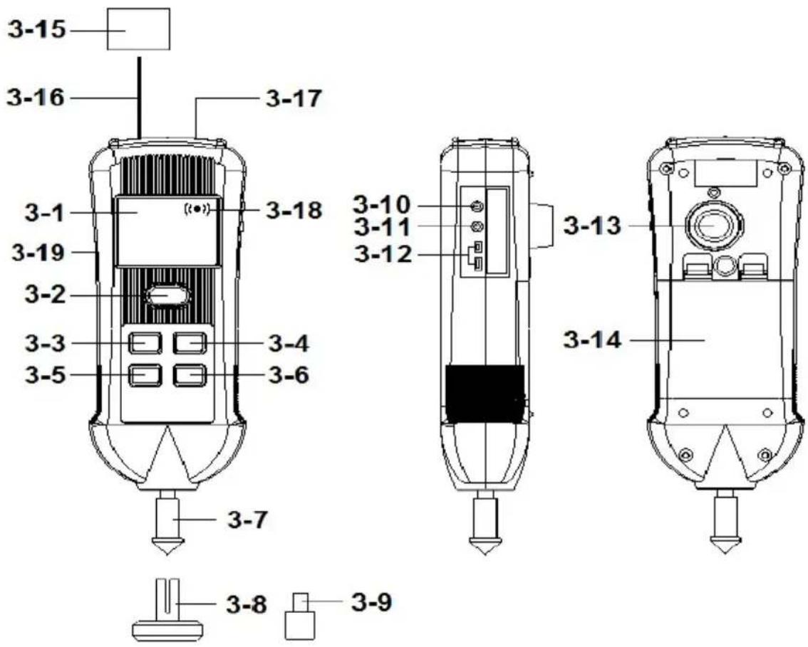
Fig. 1
3-1 Display 3-12 Thermocouple(type k) probe Terminal
3-2 Power button 3-13 IR Thermometer.
3-3 HOLD/▲ button 3-14 Battery Compartment/Cover
3-4 REC/DOUBLE button 3-15 Reflecting Mark
3-5 UNIT/▼ button 3-16 Photo led light beam
3-6 Function button 3-17 Stroboscope flash light (red) indicator
3-7 RPM Adapter 3-18 Monitor indicator
3-8 Surface Speed Test Wheel 3-19 DC 9V adapter socket
3-9 Funnel type rubber for RPM adapter
3-10 RS-232 Output Terminal
3-11 Pt 1000Ω probe Terminal
4. PHOTO TACHOMETER MEASURING PROCEDURE
1) Power On the meter by short pressing the "Power button" (3-2, Fig. 1) >1.5 seconds, the LCD will light.
2) Press the "Function button" (3-6, Fig. 1) (short push) in sequence until to the "Photo RPM" function be selected, in the same time the "Photo light beam" (3-16, Fig. 1) will be generated.
3) Apply a "Reflecting mark" (3-15, Fig. 1) to the object being measured. and align the "Photo light beam" (3-16, Fig. 1) with the applied target. Verify that the "Monitor Indicator" (3-18, Fig. 1) lights when the target pass through the light beam.
Measuring consideration :
If the measured RPM values is very low (for example less than 50 RPM), recommend to attach more "Reflecting Marks" average to the object. It will get the real RPM with high resolution, precisely & fast sampling time when divided the reading values by the no. of the "Marks".
5. CONTACT TACHOMETER MEASURING PROCEDURE
5-1 RPM measurement
1) Power On the meter by short pressing the "Power button" (3-2, Fig. 1) >1.5 seconds, the LCD will light.
2) Press the "Function button" (3-6, Fig. 1) (short push) in sequence until to the "Contact RPM" function be selected.
3) Lightly pressing the "RPM Adapter" (3-7, Fig. 1) against the center hole on the hole of the measured rotating axis.
Measuring consideration :
Making the contact RPM measurement due to different kind measured rotating axis, it may changed the rubber for RPM adapter from "CONE" type to "FUNNEL" type (3-9, Fig. 1)
5-2 Surface Speed Measurement
1) Power On the meter by short pressing the "Power button" (3-2, Fig. 1) >1.5 seconds, the LCD will light.
2) Short Press the "Function button" (3-6, Fig. 1) once again and again until Icd display show the "touch" text, then short press the "UNIT Button" to select the Surface Speed Measurement unit m/min, "ft/min" or "in./min.".
3) Change the "RPM Adapter" instead of the "Surface Speed Test Wheel" (3-8, Fig. 1)
4) Simply attaching the surface speed test wheel to the detector. approx. 2 sec. the display reading will be stabilizes.
6-1 STROBOSCOPE OPERATION
1) Power On the meter by short pressing the "Power button" (3-2, Fig. 1) >1.5 seconds, the LCD will light.
2) Press the "Function button" (3-6, Fig. 1) (short push) in sequence until to the "SCOPE RPM" function be selected, in the same time the "Stroboscope flash light (red) indicator" (3-17, Fig. 1) will be Light.
3) The display will show " last measurement value " RPM ( FPM ), last measurement value ,memo in the internal memory divice. Use the " x 2 button(▲ button) " or " / 2 button(▼ button) " to adjust the display value near the estimate setting signal's RPM approximately.
* Press and hold the "DOUBLE button" then Press " ▲ button" once will double the display value. For example, the display is "100.0", Press and hold the "DOUBLE button" then Press " ▲ button" once, the display will change to "200.0". Operation again, the display will change to "400.0".....
* Press and hold the "DOUBLE button" then Press "▼ button" once will divide the display value by two. For example, the display is "400.0", Press and hold the "DOUBLE button" then Press "▼ button" once, the display will change to "200.0". Operation again, the display will change to "100.0".....
6-2 Checking Speed (RPM/FPM)
1) Use the "▲+ button" (3-3, Fig. 1), "▼- button" (3-5, Fig. 1) to adjust the exact display value.
* Press the "▲+ button" once will increase the display value.
* Press the "▼ - button" once will decrease the display value.
* Press and hold the "▲+ button" or "▼ - button" will fast increase or fast decrease the display value.
* If press the button once, the display value will change with high resolution (change just with 1 digit).
* If press the button continuously, the display value will change with low resolution (change with more digits).
When checking the speed, care must be taken to ensure that the strobe is flashing in unison (one to one) with the object being monitored.
2) The Stroboscope will also stop motion at 2:1, 3:1, 4:1 et., this is normally referred to as harmonics. To ensure unison, turn the dial until two images appear - this will double the actual speed. Then lower the flashing rate until a single and stationary image appears - this is the actual true speed.
6-3 Checking Motion
For motion analysis, simply locate the actual speed as mentioned above and use the "▲ button" or "▼ button" to adjustment slowly up or down. This will give a slow motion effect allowing complete inspection.
7. Type K Thermometer MEASURING PROCEDURE
1) Power On the meter by short pressing the "Power button" (3-2, Fig. 1) >1.5 seconds, the LCD will light.
2) Press the "Function button" (3-6, Fig. 1) (short push) in sequence until to the "TYPE k" function be selected.
3) type k probe inserted into the thermocouple probe terminal "thermocouple probe terminal" (3-12, Fig. 1).
4) The display will show type k probe sensing temperature value.
8. RTD Temperature MEASURING PROCEDURE
1) Power On the meter by short pressing the "Power button" (3-2, Fig. 1) >1.5 seconds, the LCD will light.
2) Press the "Function button" (3-6, Fig. 1) (short push), in sequence until to the "P t" function be selected.
3) TP-1000 probes are connected to the Pt 1000 Ω probe terminal " (3-11, Fig. 1).
4) The display will show TP-1000 probe sensing temperature value.
9. Infrared Thermometer MEASURING PROCEDURE
NON-CONTACT TEMPERATURE MEASUREMENTS
1) Power On the meter by short pressing the "power button" (3-2, Fig. 1) >1.5 seconds, the LCD will light.
2) Use the "Function button" (3-6, Fig. 1)(short push), to select function , until to the "I r " function be selected.
3) Press and hold the IR thermometer test button "Power button" (3-2, Fig. 1
4) Use the led light pointer to identify the exact spot to be measured.
5) The area of the surface to be measured must be larger than the spot size as determined by the distance to spot size specification.
6) when test value stable then reless the IR thermometer test button "Power button" (3-2, Fig. 1).
7) The display will show and hold the IR sensing temperature value.
Data Record ( Max., Min. reading )
1) The data record function records the maximum and minimum readings. Press the "REC Button" (3-4, Fig.1) once to start the Data Record function and there will be a "REC "Symbol indicator" will be light.
2) With the "REC" Symbol is light on the display :
a) Press the "REC Button" (3-4, Fig. 1) once, the "REC and MAX Symbol indicator will be light, and the maximum value will appear on the display.
b) Press the "REC Button" (3-4, Fig. 1) again, the "REC and MIN" Symbol indicator will be light, and the minimum value will appear on the display.
c) To exit the memory record function, just press the "REC" button for 1.5 seconds at least. The display will revert to the current reading, Symbol indicator will be quenched
Remark :
At Infrared Thermometer and stroboscope function, the RECORD Function is disabled.
11. ADVANCED SETTING
press the "FUNCTION (SET) Button" (3-6, Fig. 1) continuously at least Five seconds will enter the "Advanced Setting" mode. then press the "FUNCTION (SET) Button" (3-6, Fig. 1) once a while in sequence to select the two main function, the display will show:
POFF..... Auto power OFF management t-CF..... Select the Temp. unit to °C or °F
Remark: wait eight seconds or short press " power button " to back measurement.
11-1 Auto power OFF management
When the lower display show "POFF"
1) Use the " ▲ button " ( 3-3, Fig. 1 ) or " ▼ button " ( 3-5, Fig. 1 " to select the upper text to " yES " or " no ".
yES - Auto Power Off management will enable. no - Auto Power Off management will disable.
2) After select the text to "yES" or "no", press the "REC(Enter) Button" (3-4, Fig.1) will save the setting function with default.
11-2 Select the Temp. unit to ℃ or ℉
When the lower display show " t-CF "
1) Use the "▲ button" (3-3, Fig. 1) or "▼ button" (3-5, Fig. 1) to select the upper Display text to "C" or "F".
C - Temperature unit is °C F - Temperature unit is °F
2) After Display unit is selected to "C" or "F", press the "REC(Enter) Button" (3-4, Fig.1) will save the setting function with default.
12. BATTERY REPLACEMENT
1) When the left corner of
Lobattery symbol " indicator
nce the battery. However, in-spec.
e for several hours after
before the instrument
is light, it is necessary to replace the battery. However, in-spec. measurement may still be made for several hours after low battery indicator appears before the instrument become inaccurate.
2) take away the "Battery Cover" (3-14, Fig. 1)
from the instrument and remove the battery.
3) Replace with DC 1.5 V battery (UM3, AA,
Alkaline/heavy duty ) x 4 PCs, and reinstate the cover.
4) Make sure the battery cover is secured after changing
the battery.

13. RS232 PC SERIAL INTERFACE
The instrument has RS232 PC serial interface via a 3.5 mm terminal (3-10, Fig. 1).
The data output is a 16 digit stream which can be utilized for user's specific application.
A RS232 lead with the following connection will be required to link the instrument with the PC serial port.
Meter PC
(9W 'D" Connector)
Center Pin.... Pin 4
(3.5 mm jack plug)
Ground/shield....
Pin 2
Pin 5
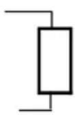
2.2 K resistor
The 16 digits data stream will be displayed in the following format :
Each digit indicates the following status :
| D15 Start Word | |||
| D14 4 | |||
| D13 1 | |||
| D12, D11 Annunciator for Display | |||
| D10 Polarity | 0 = Positive 1 = Negative | ||
| D9 Decimal Point(DP), position from right to the left0 = No DP, 1= 1 DP, 2 = 2 DP, 3 = 3 DP |
| D8 to D1 Disp ay reading, D1 = LSD, D8 = MSDFor example :If the display reading is 1234, then D8 to D1 is : 00001234 |
| D0 End Word |
RS232 FORMAT : 9600, N, 8, 1
| Baud rate 9600 | |
| Parity No parity | |
| Data bit no. 8 Data bits | |
| Stop bit 1 Stop bit |
- AUTOMOTIVE TESTER
- TABLE OF CONTENTS
- FEATURES
- SPECIFICATIONS
- 2-1 General Specifications
- FRONT PANEL DESCRIPTION
- PHOTO TACHOMETER MEASURING PROCEDURE
- Measuring consideration :
- CONTACT TACHOMETER MEASURING PROCEDURE
- 5-1 RPM measurement
- 5-2 Surface Speed Measurement
- 6-1 STROBOSCOPE OPERATION
- 6-2 Checking Speed (RPM/FPM)
- When checking the speed, care must be taken to ensure that the strobe is flashing in unison (one to one) with the object being monitored.
- 6-3 Checking Motion
- Type K Thermometer MEASURING PROCEDURE
- RTD Temperature MEASURING PROCEDURE
- Infrared Thermometer MEASURING PROCEDURE
- NON-CONTACT TEMPERATURE MEASUREMENTS
- Data Record ( Max., Min. reading )
- Remark :
- ADVANCED SETTING
- 11-1 Auto power OFF management
- 11-2 Select the Temp. unit to ℃ or ℉
- BATTERY REPLACEMENT
- RS232 PC SERIAL INTERFACE
Brand : PCE Instruments
Model : T 260
Category : Tachometer