
ACAC75017 - Uncategorized APC - Free user manual and instructions
Find the device manual for free ACAC75017 APC in PDF.


| Product Type | Uninterruptible Power Supply (UPS) |
| Model | ACAC75017 |
| Brand | APC |
| VA Rating | 750 VA |
| Watt Rating | 450 W |
| Input Voltage | 120 V AC |
| Output Voltage | 120 V AC |
| Frequency | 60 Hz |
| Battery Type | Sealed Lead-Acid |
| Battery Runtime (half load) | ~15 minutes |
| Surge Protection | Yes, 459 Joules |
| AVR (Automatic Voltage Regulation) | Yes |
| Dimensions (H x W x D) | 14.0 x 10.5 x 7.5 in (35.6 x 26.7 x 19.1 cm) |
| Weight | 20.5 lbs (9.3 kg) |
| Operating Temperature | 32°F to 104°F (0°C to 40°C) |
| Charging Time | 6 hours |
| Number of Outlets | 6 (battery backup + surge) |
| Warranty | 3 years |
| Included Accessories | User manual, USB cable |
| Maintenance | Replace battery every 2-3 years |
| Safety Certifications | UL 1778 |
Frequently Asked Questions - ACAC75017 APC
User questions about ACAC75017 APC
0 question about this device. Answer the ones you know or ask your own.
Ask a new question about this device
Download the instructions for your Uncategorized in PDF format for free! Find your manual ACAC75017 - APC and take your electronic device back in hand. On this page are published all the documents necessary for the use of your device. ACAC75017 by APC.
USER MANUAL ACAC75017 APC
ACAC75016 and ACAC75017—Low Temperature Kit

The low temperature kit provided by Schneider Electric includes a pressure relief valve on the liquid receiver vessel. If the low temperature kit is not installed, the Schneider Electric recommends the installation of a pressure relief valve on the discharge pipe near the condenser. The pressure relief valve selection and installation is the responsibility of the installer and shall comply with local authorities.
Install Kit Inventory
EMEA-PED Versions (ACAC75017)
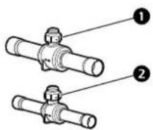
natural_image
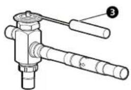
Technical line drawing of a mechanical tool with no visible text or symbols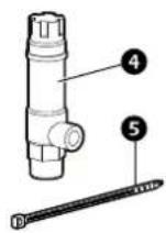
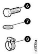
Item Description Quantity Item Description Quantity
| 1 | Ball valve, 7/8 in. (inlet) 1 Tie wrap, 1 1/4 in. (not 5 used) | 11 |
| 2 | Ball valve, 5/8 in. (outlet) 1 (not used) | Bolt, M6 (not used) 16 |
| 3 | Head pressure valve and check valve 1 | Washer flat, M6 (not used) 16 |
| 4 | Safety valve (PED) 1 | Hose clamp 2 |
NAM-ASME Versions (ACAC75016)
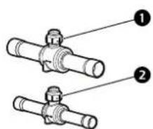
natural_image
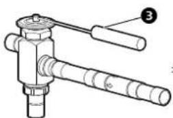
Technical line drawing of a mechanical valve assembly (no text or symbols)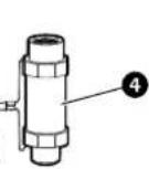
Item Description Quantity Item Description Quantity
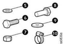
| 1 | Ball valve, 7/8 in. (inlet) | 1 Bolt, 1/4 in. (6t used) | 2 | |
| 2 | Ball valve, 5/8 in. (outlet) (not used) | 1 | 7 Nut, M10 (not used) | 4 |
| 3 | Head pressure valve and check valve | 1 | 8 Bolt, M10 (not used) | 4 |
| Item | Description | Quantity | Item | Description | Quantity | ||||
| 4 | Safety valve (ASME) | 1 | Washer flat, M10 (not used) | 9 | 4 | ||||
| 5 | Washer flat, 1/4 in. (not used) | 2 | 10 | Hose clamp 2 | |||||
Unpacking
EMEA-PED Versions (ACAC75017)
- Remove plywood top and sides from the pallet.
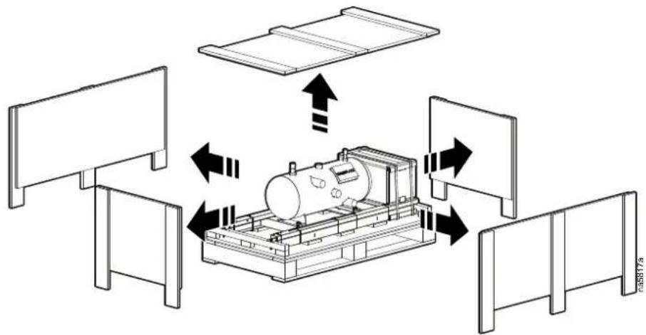
flowchart
graph TD
    A["Top Panel"] --> B["Central Tank"]
    C["Left Panel"] --> B
    D["Right Panel"] --> B
    B --> E["Bottom Panel"]
    style A fill:#f9f,stroke:#333
    style C fill:#f9f,stroke:#333
    style D fill:#f9f,stroke:#333
    style B fill:#ccf,stroke:#333
    style E fill:#ccf,stroke:#333
- Remove the valve box (contains safety valve, ball valve, head pressure valve, and check valve).
- Remove brackets.
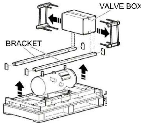
- Remove receiver kit.
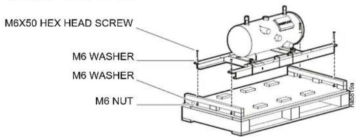
NAM-ASME Versions (ACAC75016)
- Remove plywood top and sides from the pallet.
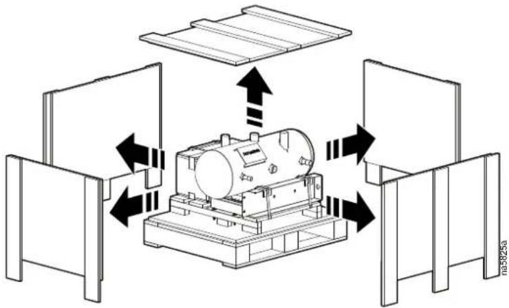
flowchart
graph TD
    A["Top Tank"] --> B["Central Tank"]
    B --> C["Bottom Tank"]
    C --> D["Top Tank"]
    style A fill:#f9f,stroke:#333
    style B fill:#ccf,stroke:#333
    style C fill:#cfc,stroke:#333
    style D fill:#fcc,stroke:#333
- Remove the valve box (contains safety valve, ball valve, head pressure valve and check valve).
- Remove brackets.
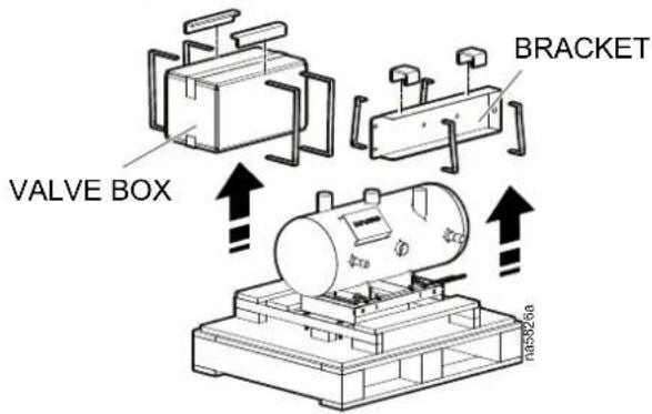
- Remove receiver kit.
Installation
ACAC75016—NAM-ASME Kit
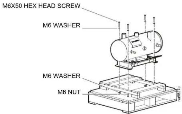
- Remove the receiver from the mounting bracket.
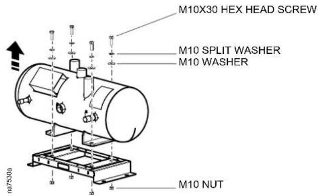
- Attach the receiver to the mounting bracket from the low temperature accessory kit with hardware from the accessory kit.
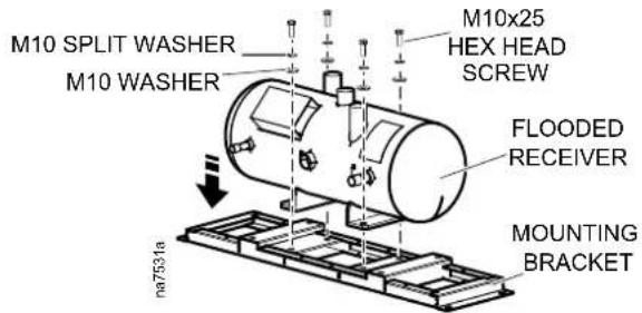
- Attach the receiver to the side of the ACCU30X unit and connect the cable conduit.
NOTE: The cable conduit can be cut to size; use caution to avoid cutting the cable inside.
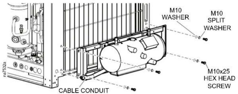
- Install the safety valve, head pressure valve, ball valve, pipe reducers, and field piping from the receiver to the ACCU30X unit.
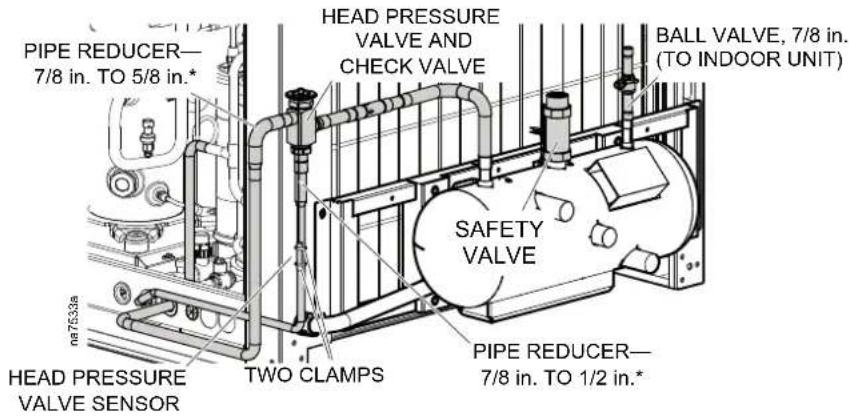
NOTE: *Items are included in the accessory kit.
ACAC75017—EMEA-PED Kit
- Remove the receiver from the mounting bracket. Disconnect the conduit from the junction box and remove the junction box.
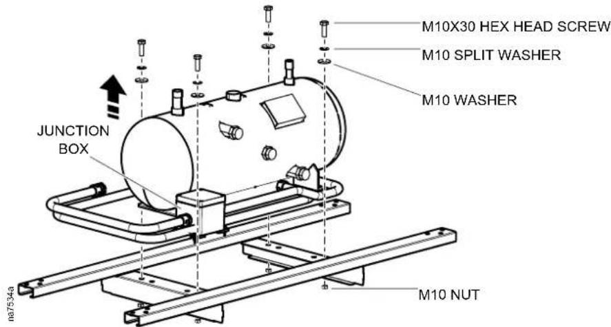
- Attach the receiver to the mounting bracket from the low temperature accessory kit with hardware from the accessory kit.
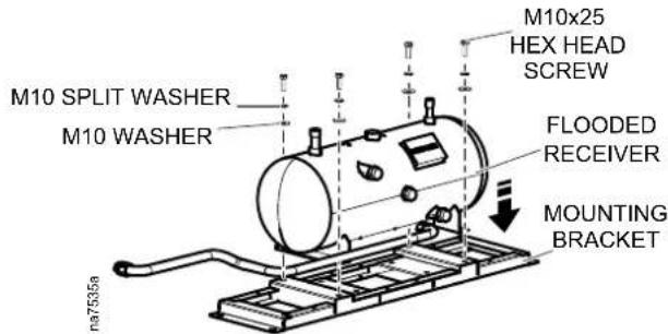
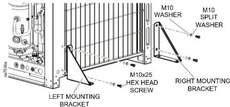
- Connect the left and right mounting brackets from the accessory kit to the side of the ACCU30X unit.
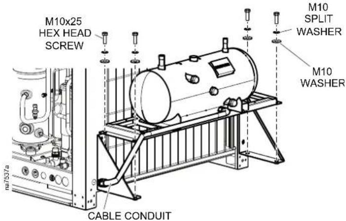
- Attach the receiver to the mounting brackets and connect the cable conduit.
NOTE: The cable conduit can be cut to size; use caution to avoid cut the cable inside.
- Install the safety valve, head pressure valve, ball valve, pipe reducers, and field piping from the receiver to the ACCU30X unit.
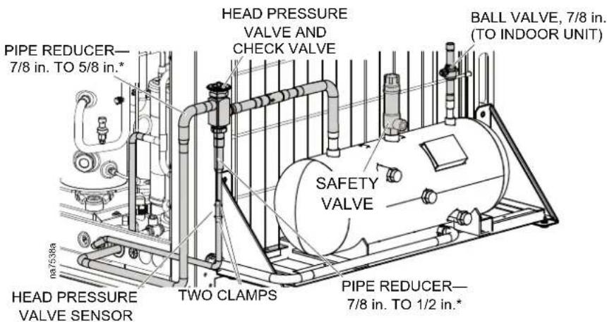
NOTE: *Items are included in the accessory kit.
Electrical Connection
⚠️ DANGER
HAZARD OF ELECTRIC SHOCK, EXPLOSION, OR ARC FLASH
- Apply appropriate personal protective equipment (PPE) and follow safe electrical work practices.
- This equipment must be installed and serviced by qualified and trained personnel only.
- Turn off all power supplying this equipment before working on or inside the equipment.
- Replace all devices, doors, and covers before turning on power to this equipment.
Failure to follow these instructions will result in death or serious injury.
Route the cable from the flooded receiver to the ACCU30X electrical panel as shown below.
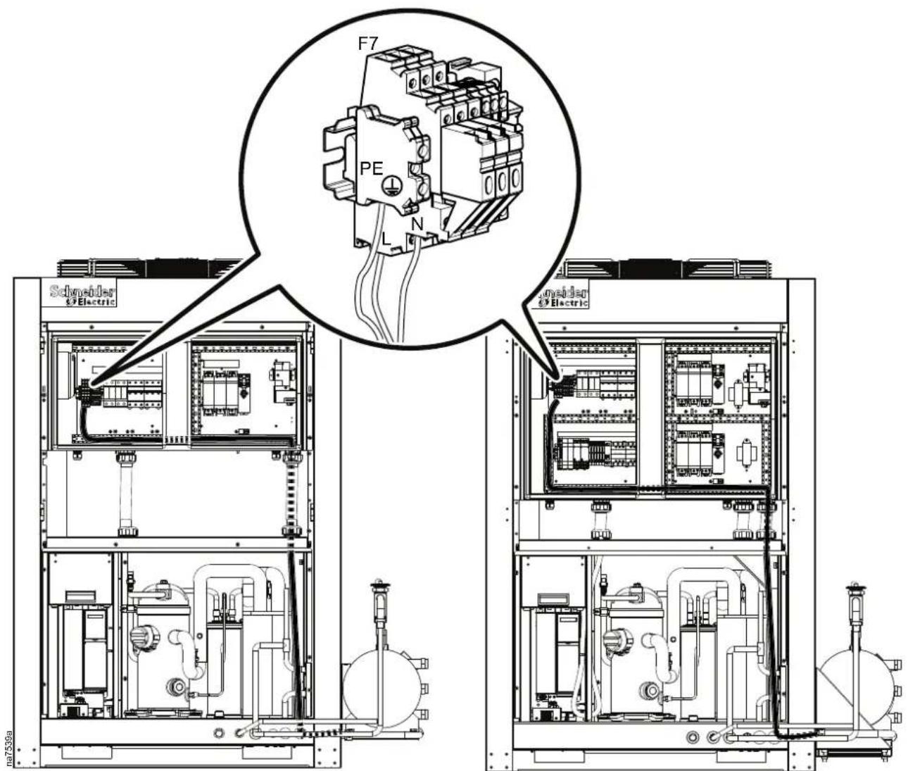
WITHOUT ATS WITH ATS
Brand : APC
Model : ACAC75017
Category : Uncategorized