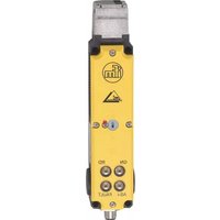
AC902S - Safety switch IFM - Free user manual and instructions
Find the device manual for free AC902S IFM in PDF.


| Product Type | AC Current Sensor |
| Model | AC902S |
| Brand | IFM |
| Dimensions (W x H x D) | 30 mm x 60 mm x 90 mm |
| Weight | Approx. 150 g |
| Power Supply | 24 V DC, ±10% |
| Current Measurement Range | 0-100 A AC |
| Output Type | Analog 4-20 mA |
| Accuracy | ±1% of reading |
| Operating Temperature | -25°C to +70°C |
| Protection Rating | IP67 |
| Housing Material | Polyamide, UL94 V-2 |
| Mounting | DIN rail or screw fixing |
| Cable Connection | Screw terminals, 1.5 mm² |
| Functions | AC current measurement, overload indication, self-diagnosis |
| Maintenance | Periodic visual inspection; clean with dry cloth |
| Safety | Use only with specified supply voltage; avoid moisture ingress |
| Spare Parts | Sealing caps, terminal blocks, mounting brackets |
| Repairability | Replaceable fuse (internal); consult factory for other repairs |
| General Information | Designed for industrial AC current monitoring; CE, RoHS compliant |
Frequently Asked Questions - AC902S IFM
User questions about AC902S IFM
0 question about this device. Answer the ones you know or ask your own.
Ask a new question about this device
Download the instructions for your Safety switch in PDF format for free! Find your manual AC902S - IFM and take your electronic device back in hand. On this page are published all the documents necessary for the use of your device. AC902S by IFM.
USER MANUAL AC902S IFM
Original operating instructions Safety switch with guard locking
AC901S
AC902S
UK
7390914/03 01/2017

natural_image
Technical line drawing of a cylindrical mechanical component with mounting holes and internal circular features (no text or symbols)Contents
1 Preliminary note....4
1.1 Explanation of symbols....4
2 Safety instructions ....4
3 Items supplied....5
4 Functions and features ....5
5 Structure and operating principle....7
5.1 Actuator version....7
5.2 Version AC901S (guard locking by spring force)....7
5.3 Version AC902S (guard locking by solenoid force) 8
5.4 Mechanical release....9
6 Installation....10
6.1 Installation instructions .... 10
6.1.1 Changing the actuating direction.... 11
6.2 Protection against environmental influences.... 11
7 Electrical connection....11
7.1 Wiring....12
8 Set-up 12
8.1 Setting of the AS-Interface address....12
8.2 Configuration in the AS-Interface safety monitor 12
8.2.1 Monitor with extended functions....13
9 Operation....14
9.1 LED indicators / AS-Interface status messages .... 14
10 Function check and troubleshooting....14
10.1 Mechanical function check 14
10.2 Electrical function check....15
10.3 Troubleshooting....15
11 Scale drawing 16
12 Technical data....17
13 Terms and abbreviations.... 18
14 Data bit table....19
15 Standards and approvals....22
15.1 Directives and standards 22
15.2 Approvals....22

1 Preliminary note
Technical data, approvals, accessories and further information at www.ifm.com.
1.1 Explanation of symbols
▶ Instruction
Reaction, result
→ Cross-reference

Important note
Non-compliance may result in malfunction or interference.

Information
Supplementary note.

WARNING
Warning of serious personal injury.
Death or serious irreversible injuries may result.
2 Safety instructions
Read this document before setting up the product and keep it during the entire service life.
- The product must be suitable for the corresponding applications and environmental conditions without any restrictions.
- Only use the product for its intended purpose (→ Functions and features).
- If the operating instructions or the technical data are not adhered to, personal injury and/or damage to property may occur.
- The manufacturer assumes no liability or warranty for any consequences caused by tampering with the product or incorrect use by the operator.
- Installation, electrical connection, set-up, operation and maintenance of the unit must be carried out by qualified personnel authorised by the machine operator.
- Protect units and cables against damage.
- Also adhere to the safety instructions for the operation of the whole installation.
-
The applicable technical standards for the corresponding application must be complied with.
-
For installation the requirements according to EN 60204-1 must be observed.
- Disconnect the unit externally before handling it. Also disconnect any independently supplied relay load circuits.
• After installation of the system perform a complete function check. - Only use the unit under the specified operating conditions ( 12 Technical data). In case of special operating conditions please contact the manufacturer.
- Safety switches fulfil a personal protection function. Incorrect installation or tampering can lead to serious injury.
- Safety components must not be bypassed (bridging of contacts), turned away, removed or otherwise rendered ineffective.
- On this point, take particular note of the measures to reduce the possibilities of bypassing in EN ISO 14119: 2013.
- The switching operation must only be triggered by actuators specially provided for this purpose which are permanently connected to the safety guard.
- A complete safety-related system normally consists of several signalling devices, sensors, evaluation units and concepts for a safe shut-down. The manufacturer of a machine or installation is responsible for a correct and safe overall function.
- All safety instructions and specifications in the operating instructions of the AS-Interface safety monitor must be adhered to.
3 Items supplied
• 1 AS-Interface safety switch type AC90xS
• 1 operating instructions safety switch with guard locking, ident no. 7390914.
If one of the above-mentioned components is missing or damaged, please contact one of the ifm branch offices.
4 Functions and features
AS-Interface safety switches type AC901S/AC902S operate as slaves on the safety bus AS-Interface Safety at Work and function as electromagnetic interlock devices with guard locking. The actuator has a low coding level.
In combination with a guard and the machine control system this safety component prevents the safety guard from being opened while there is potential of
exposure to a mechanical hazard.
For the control system this means the following:
- Switch-on commands which cause hazardous situations must become active only when the safety guard is in a protective position and the guard locking in locked position.
- The locked position of the guard locking must be released only when the hazardous situation is no longer present.
- Closing and guard locking a safety guard must not cause automatic start of a dangerous machine function. A separate start command has to be given. For exceptions see EN ISO 12100 or relevant C standards.
Before safety switches are used, a risk assessment must be performed on the machine, e.g. according to
- EN ISO 13849, Safety of machinery - Safety-related parts of control systems
- EN 12100-1, Safety of machinery - General principles for design - Risk assessment and risk reduction
Correct use includes compliance with the relevant requirements for installation and operation, in particular
- IEC 62061, Safety of machinery - Functional safety of safety-related electrical, electronic and programmable electronic control systems
- EN ISO 13849, Safety of machinery - Safety-related parts of control systems
- EN 14119, Interlocking devices associated with guards
- EN 60204-1, Electrical equipment of machines.

The user is responsible for a safe integration of the device into a safe overall system.
▶ Validate the whole system, e.g. to EN ISO 13849-2.
If the simplified procedure to EN ISO 13849-1: 2016 (section 6.3) is used for validation, the performance level (PL) may be reduced in the event of several units being connected in series. If a data sheet is supplied with the product, the specifications of the data sheet apply in case of deviations from the operating instructions.
5 Structure and operating principle
AS-Interface safety switches, type AC901S/AC902S feature a slave interface to the safety bus AS-Interface Safety at Work. They enable locking of movable safety guards.
In the switch head there is a rotating switch cylinder that is locked/released by the guard locking bolt.
When the actuator is introduced/removed and the guard locking is activated/unlocked, the locking bolt is moved. The switching contacts are activated.
When the switch cylinder (guard locking active) is locked, the actuator cannot be removed from the switch head. For reasons of design the guard locking can only be activated if the protective equipment is closed (protected against incorrect locking).
Position monitoring of the safety guard and monitoring of interlocking are performed via two separate contact elements (door monitoring contact SK and solenoid monitoring contact ÜK).
When the safety guard is closed and the guard locking is active, each AS-i safety switch transmits a switch-specific unique safety code sequence comprising 8x4 bits via the AS-Interface bus. This code sequence is evaluated by an AS-Interface safety monitor. The positively driven contact SK for door monitoring is represented by the AS-Interface input bits D0 and D1. The solenoid monitoring contact ÜK is represented by the AS-Interface input bits D2 and D3.
▶ Configure the safety switch in the AS-Interface safety monitor accordingly (refer to the operating instructions of the AS-Interface safety monitor and the data bit table).
The fail-safe switch is designed so that the exclusion of internal faults according to EN ISO 13849 2: 2013, Table A4 can be assumed.
5.1 Actuator version
Actuator S for the AS-i safety switches AC901S/AC902S without insertion funnel.
5.2 Version AC901S (guard locking by spring force)
Additional measure for personal protection against dangerous overtravel movements:
▶ Connect the black AS-Interface cable (auxiliary power) to the AS-Interface splitter via a standstill monitor or via the safe switch-on delay of a two-channel AS-Interface safety monitor (e.g. door locking for the duration of the delay time). The switches are connected to the AS-Interface splitter.
The locking bolt is held in locked position by spring force and is electromagnetically released. The spring-interlocked guard locking operates normally closed. In the event of interruption of the solenoid power supply the safety guard cannot be opened immediately.
For process protection the interlocking solenoid can be switched by software via the AS-Interface output bit D0.
If the safety guard is open when the power supply is interrupted and the guard is then closed, guard locking is activated. This can lead to persons being locked in unintentionally.
5.3 Version AC902S (guard locking by solenoid force)

Use as guard locking for operator protection is only possible in special cases after a strict assessment of the risk of accident (see EN ISO 14119:2013, section 5.7.1).
In the event of interruption of the solenoid power supply the safety guard can be opened immediately!
The locking bolt is electromagnetically held in locked position and released by spring force. The guard locking operates normally open.
▶ For process protection switch the interlocking solenoid by software via the AS-Interface output bit D0.
▶ Close the safety guard and activate the guard locking.
▶ Insert the actuator into the safety switch.
The locking bolt is released.
- AC901S: The locking bolt passes into the locked position by spring force.
- AC902S: The locking bolt passes into the locked position by applying the operating voltage of the solenoid.
The safety contacts close.
The whole safety code sequence (8 x 4 bits) is transmitted via the AS-Interface input bits D0 to D3.
▶ Deactivate the guard locking and open the safety guard.
AC901S
▶ Apply the operating voltage of the solenoid and release the guard locking via the AS-Interface output bit D0.
The guard locking is deactivated, the solenoid monitoring contact ÜK opens. The value pair 0, 0 is transmitted in every bus cycle via the AS-Interface input bits D2 and D3.
▶ Remove the actuator.
The door monitoring contact SK is positively opened and the guard locking is blocked in this position (protection against unintentional closing). The values 0, 0, 0, 0 are continuously transmitted via the AS-Interface input bits D0 to D3.
AC902S
▶ Switch off the operating voltage of the solenoid and release the guard locking via the AS-Interface output bit D0.
The guard locking is deactivated, the solenoid monitoring contact ÜK opens. The value pair 0, 0 is transmitted in every bus cycle via the AS-Interface input bits D2 and D3.
▶ Remove the actuator.
The door monitoring contact SK is positively opened and the guard locking is blocked in this position (protection against unintentional closing). The values 0, 0, 0, 0 are continuously transmitted via the AS-Interface input bits D0 to D3.
5.4 Mechanical release
In the event of malfunction the guard locking can be released with the mechanical release irrespective of the state of the solenoid ( 6.1.1).
▶ Remove the locking screw.
▶ Using a screwdriver, turn the mechanical release by approx. 180^ in direction of the arrow.
▶ The locking screw must be returned to its original position and sealed after use (for example with sealing lacquer).
▶ After unlocking perform a complete function check. For further information we refer you to EN ISO 14119: 2013, section 5.7.5.1.
6 Installation
Do not use safety switches and actuators as an end stop and only mount in assembled condition.
▶ At ambient temperatures higher than 40 °C protect the switch against contact with inflammable material or personnel.
6.1 Installation instructions
▶ Mount the safety switch so that
- access to the switch is difficult for operators when the safety guard is open and the operation of the mechanical release is still possible.
- address programming, inspection and replacement by authorised personnel is possible.
▶ Insert the actuator into the actuating head.
▶ Mount the safety switch positively.
▶ Permanently connect the actuator to the safety guard so that it cannot be detached (e.g. using the enclosed non-removable screws), alternatively rivet or weld.
▶ Fit an additional end stop for the movable part of the safety guard.

To fix the fail-safe switch and the actuator adhere to EN ISO 14119:2013, sections 5.2 and 5.3.
To minimize defeat possibilities of an interlocking device adhere to EN ISO 14119:2013, section 7.
6.1.1 Changing the actuating direction

flowchart
graph TD
    A["Motor 1"] -->|Rotating| B["Component 1"]
    B --> C["Component 2"]
    C --> D["Component 3"]
    D --> E["Component 4"]
    E --> F["Component 5"]
    style A fill:#f9f,stroke:#333
    style B fill:#ccf,stroke:#333
    style C fill:#cfc,stroke:#333
    style D fill:#fcc,stroke:#333
    style E fill:#cff,stroke:#333
    style F fill:#ffc,stroke:#333
▶ Remove the screws from the actuating head.
▶ Set the required direction.
▶ Tighten the screws with 0.6 Nm.
▶ Close the unused actuating slots with the supplied slot covers.
6.2 Protection against environmental influences
A lasting and correct safety function requires that the actuating head must be protected against the penetration of foreign bodies such as swarf, sand, blasting shot etc.
▶ Cover the actuating slot, the actuator and the type label during paint work.
7 Electrical connection
▶ For use and operation as per the UL requirements use an isolating transformer or a power supply with secondary overcurrent protection (3 A).
7.1 Wiring
The safety switch is connected to the bus system with an M12 connector and a 4-pole cable. Additionally, via a passive AS-Interface splitter with a yellow and black AS-Interface cable.

- AS-Interface +
- Auxiliary voltage
- AS-Interface -
- Auxiliary voltage 24 V
8 Set-up
8.1 Setting of the AS-Interface address
The address can be set before or after installation.
▶ Set the AS-Interface address of the safety switch using an AS-Interface programming device. Addresses 1 to 31 are valid.
▶ Connect the programming device to the M12 connector of the safety switch using a programming cable.
Address 0 is the default setting on delivery (the AS-Interface LED Fault is lit during operation).
8.2 Configuration in the AS-Interface safety monitor
Refer to the operating instructions of the AS-Interface safety monitor and the data bit table.
Configure the safety switch in the AS-Interface safety monitor with the set AS-Interface address, for example, as follows:
Dual-channel dependent
- synchronisation time = infinite ( )
In this operating mode, the safety guard must be opened each time prior to restarting in order to perform the start-up test.
Dual-channel independent
The guard locking is opened or closed via the output D0. When the guard locking is open, the safety circuit shuts down. It is not necessary to open the door. Safety is provided again when the guard locking is closed.
The dual-channel feature and the door contact are not tested in this configuration. Take additional measures for testing outside the monitor.
8.2.1 Monitor with extended functions
For the monitor with extended functions the following configuration is possible:
- dual-channel conditionally dependent
- independent: In-1
The guard locking is opened or closed via the output D0. When the guard locking is open, the safety circuit shuts down. It is not necessary to open the door. Safety is provided again when the guard locking is closed.
The switch is monitored for malfunction, the door contact (SK) must not switch before the guard locking contact (ÜK).
Observe the following if in the event of a spring-interlocked safety switch AC901S the interlocking solenoid is switched on (released) in the operating mode door locking for duration of the delay time via the second release contact of a dual-channel safety monitor and a PLC:
- It is not possible to switch off the interlocking solenoid by means of the monitor alone. The control system (PLC) must switch off the interlocking solenoid in the locked position via the AS-Interface output D0 = 0 in order to re-establish the switch-on conditions for the first OSSD.
- Switch on the AS-Interface output with D0 = 1 so that the interlocking solenoid can be released by the second safety output of the monitor.
Status signals (not relevant to safety)
The status of the AS-Interface input bits D0 and D1 for door monitoring and AS-Interface input bits D2 and D3 for solenoid monitoring can also be polled by the control system (PLC) (see the operating instructions of the AS-Interface safety monitor).
9 Operation
9.1 LED indicators / AS-Interface status messages
| StatusLED 3 FaultandLED 4 Power | Device status | |
 | green is lit normal operation | |
| red and green are lit - slave address = 0or- offline phase | ||
1: LED green
2: LED red
3: LED red FAULT
4: LED green Power
The AS-Interface bus status is indicated by two LEDs (Power, Fault). Two additional LEDs can be connected via the AS-Interface bus, e.g. to indicate the status signals (see Status signals and Technical data).
10 Function check and troubleshooting

WARNING
Errors during installation and function check can lead to fatal injury.
▶ Before the function check ensure that there are no persons in the hazardous area.
▶ Adhere to the applicable accident prevention regulations.
▶ After installation and each error carry out a complete check of the safety function.
10.1 Mechanical function check
The actuator must slide easily into the actuating head.
▶ Close the safety guard several times to check the function.
10.2 Electrical function check
▶ 1. Switch on the operating voltage.
▶ 2. Close all safety guards.
▶ In case of guard locking by means of solenoid force activate the guard locking.
The machine must not start automatically. It must not be possible to open the safety guard.
▶ 3. Activate operation in the controller
It must not be possible to deactivate the guard locking as long as the operation is active.
▶ 4. Switch off the operation in the controller and deactivate the guard locking.
The safety guard must remain locked until there is no longer a risk of injury. It must not be possible to start the machine as long as the guard locking is deactivated.
▶ Repeat steps 2 - 4 for every safety guard individually.
10.3 Troubleshooting
▶ In case of damage or wear replace the complete switch and actuator assembly. Replacement of individual parts or assemblies, especially of the actuating head, is not permitted!

The production year is indicated in the bottom right corner of the type label.

See EN ISO 14119: 2013, section 8.2 for notes on possible time intervals.
To ensure a trouble-free long-term operation regular inspections are necessary.
▶ Check the unit for the following points:
- correct switching function
- secure mounting of the components
- dirt and wear
- loose connectors
Exclusion of liability under the following circumstances:
- if the unit is not used for its intended purpose

- non-compliance with the safety regulations
- installation and electrical connection by non-authorised personnel
- failure to perform function checks.
11 Scale drawing
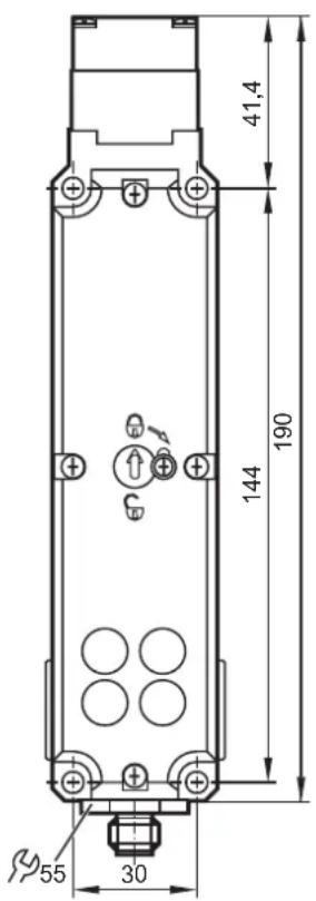
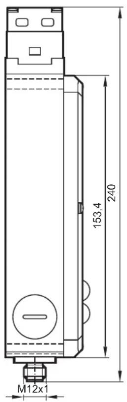

12 Technical data
| AC901S, AC902SSafety switch with guard lockingThe device can be used in applications according to EN ISO 13849-1: 2016 up to PL d. | |
| Mechanical data | |
| Housing material | reinforced glass-fibre thermoplastic |
| Degree of protection to IEC 529 | IP 67, mating connector plugged in |
| Lifetime | 1 × 10^6 operating cycles |
| Ambient temperature | -20...55 °C |
| Installation position | freely selectable |
| Max. approach speed | 20 m/min |
| Actuation frequency | 1200 / h |
| Actuation force | 35 N |
| Extraction force | 30 N (not locked) |
| Retention force | 20 N |
| Locking force F_max | 2500 N |
| Locking force F_Zh in accordance with the test principles GS-ET-19 | F_Zh = (F_max/ 1.3) = 2000 N |
| Weight | approx. 0.5 kg |
| Switching principle SK, ÜK | positively driven, slow-action switching element |
| Interlocking solenoid | |
| Solenoid operating voltage (auxiliary voltage on the black AS-Interface cable) | DC 24 V +10% / -15%, 8 Wpower supply with safe isolation(IEC 60742, PELV) |
| Solenoid operating current | 300 mA |
| Duty cycle | 100 % |
| Connection type | M12 connector |
| Minimum travel and overtravel | |
| Approach direction | actuator S (standard) |
| Horizontal (h) and vertical (v) | 24.5 + 5 |
| AS-Interface specifications | |
| AS-Interface operating voltage | 22.5 ... 31.6 V DC |
| Max. total current consumption | 45 mA |
| AS-Interface / extended addressing mode possible | version 2.1 / no |
| AS-i profile | S-7.B.E |
| Valid AS-Interface addresses | 1...31 |
| AS-i certificate | 96101 |
| AS-Interface inputs | |
| Door monitoring contact SK | D0, D1 |
| Solenoid monitoring contact ÜK | D2, D3 |
| AS-Interface outputs | |
| D0 | interlocking solenoid, 1 = solenoid energised |
| D1 | LED red, 1 = LED on |
| D2 | LED green, 1 = LED on |
| AS-Interface LED Power | green, AS-Interface voltage applied |
| AS-Interface LED Fault | red, offline phase or address "0" |
| Reliability values to EN ISO 13849-1 | |
| B10d | 5 x 10^6 |
13 Terms and abbreviations
| PL Performance | level Capability of safety-related | parts to perform a safety function under predictable conditions to fulfil the expected risk reduction. |
| B10d Number of cycles, up to 10% of the | components with dangerous failure. | |
14 Data bit table


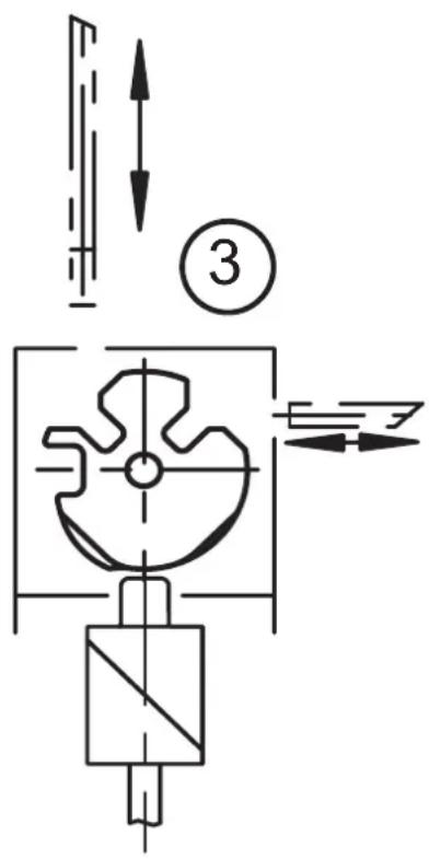
1: Safety guard closed and locked
2: Safety guard closed and not locked
3: Safety guard open
| Programming | Status D0, D1 | D2, D3 | Monitor | diagnostics |
| Dual channel conditionally dependent | Safety guard closed and locked | Code sequence Green | ||
| Safety guard closed and not locked | Half sequence | 00 Yellow flashing | ||
| Invalid status (safety guard open, guard locking active) | 00 Half | sequence | Flashing red (monitoring of the invalid status) | |
| Safety guard open 00 | 00 Red | |||
| Address 0 or communication disturbed | — Grey | |||
| Programming | Status D0, D1 | D2, D3 Monitor | diagnostics | |
| Dual channel independent | Safety guard closed and locked | Code sequence Green | ||
| Safety guard closed and not locked | Half sequence | 00 Red | ||
| Invalid status (safety guard open, guard locking active) | 00 Half | sequence | Red | |
| Safety guard open 00 | 00 Red | |||
| Address 0 or communication disturbed | — Grey | |||
| Dual channel dependent Synchronisation time infinite | Safety guard closed and locked | Code sequence Green | if safety guard was open before or flashing yellow after start-up, if only guard locking was open. | |
| Safety guard closed and not locked | Half sequence | 00 Flashing yellow, if safety guard was closed before. Red, if safety guard was open before. | ||
| Invalid status (safety guard open, guard locking active) | 00 Half | sequence | Flashing yellow, if safety guard was closed before. Red, if safety guard was open before. | |
| Safety guard open 00 | 00 Red | |||
| Address 0 or communication disturbed | — Grey | |||
15 Standards and approvals
15.1 Directives and standards
The following standards and directives have been applied:
- Machinery Directive 2006/42/EC
- EN ISO 13849-1: 2016
- EN 62026-2: 2013
- EN 60947-5-1: 2004/: 2009
- EN 60947-5-1: 2004/: 2009 - Annex K
- EN 14119: 2013
15.2 Approvals
- EU declaration of conformity
- UL (cULus)
- AS-i certificate
UK
- Contents
- Preliminary note
- Explanation of symbols
- WARNING
- Safety instructions
- Items supplied
- Functions and features
- Structure and operating principle
- Actuator version
- Version AC901S (guard locking by spring force)
- Version AC902S (guard locking by solenoid force)
- AC901S
- AC902S
- Mechanical release
- Installation
- Installation instructions
- Changing the actuating direction
- Protection against environmental influences
- Electrical connection
- Wiring
- Set-up
- Setting of the AS-Interface address
- Configuration in the AS-Interface safety monitor
- Dual-channel dependent
- Dual-channel independent
- Monitor with extended functions
- Status signals (not relevant to safety)
- Operation
- LED indicators / AS-Interface status messages
- Function check and troubleshooting
- Mechanical function check
- Electrical function check
- Troubleshooting
- Scale drawing
- Technical data
- Terms and abbreviations
- Data bit table
- Standards and approvals
- Directives and standards
- Approvals
Brand : IFM
Model : AC902S
Category : Safety switch