Pick your language and provide your email: we'll send you a specifically translated version.
This manual is not available in your language
Type de produit
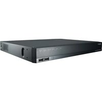
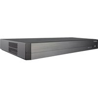
Network Video Recorder (NVR)
Modèle
SRN-473SP
Marque
Hanwha
Résolution d'enregistrement max
8 MP (3840x2160)
Nombre de canaux
4 canaux PoE
Capacité de stockage interne
1 baie HDD SATA (max 1 disque)
Alimentation
Entrée secteur 100-240 VAC, 50/60 Hz
Consommation électrique
50 W (max avec PoE)
Sorties vidéo
1x VGA, 1x HDMI
Sortie audio
1x RCA (jack audio)
Ports réseau
1x Ethernet 10/100/1000 Base-T
Ports USB
1x USB 2.0 (avant)
Entrées alarme
2 (NO/NC)
Sorties alarme
1 (relais)
Protocoles pris en charge
ONVIF Profile S, RTP/RTSP, Hanwha propriétaire
Modes d'enregistrement
Continu, événement, programmé
Méthodes de recherche
Par heure, événement, texte, sauvegarde
Fonctions PTZ
Prise en charge via réseau (Hanwha, ONVIF)
Sécurité
Mot de passe administrateur, gestion des utilisateurs et des groupes, connexion sécurisée
Température de fonctionnement
0 °C à 40 °C
Dimensions (L x P x H)
Environ 370 x 300 x 44 mm (montage en rack 1U)
Poids
Environ 3 kg (sans disque dur)
Accessoires inclus
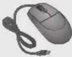
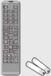
Souris NVR, câble d'alimentation, télécommande (avec piles), CD logiciel, kit de montage en rack
Frequently Asked Questions - SRN-473SP Hanwha
Comment réinitialiser le mot de passe administrateur ?
Si vous avez oublié le mot de passe, vous devez contacter le support technique. La réinitialisation matérielle n'est pas décrite dans le manuel. Assurez-vous de définir un mot de passe fort lors de la première connexion avec l'ID admin.
Comment connecter une caméra réseau au SRN-473SP ?
Utilisez l'interface de configuration du NVR. Allez dans Menu > Device > Camera > Cam Registration. Vous pouvez rechercher automatiquement les caméras sur le réseau ou les ajouter manuellement en spécifiant le protocole (ONVIF, RTSP, SAMSUNG) et l'adresse IP.
Quelle est la résolution maximale prise en charge ?
Le SRN-473SP prend en charge l'enregistrement jusqu'à 8 mégapixels (3840x2160) pour les caméras compatibles.
Comment effectuer une sauvegarde des enregistrements ?
Connectez un périphérique USB (clé ou disque dur) au port USB avant. Allez dans le menu Live ou Search, sélectionnez les chaînes et la plage horaire, puis cliquez sur Backup. Le format recommandé est FAT32.
Puis-je visionner les caméras à distance ?
Oui, via le logiciel Web Viewer ou Network Viewer fourni. Assurez-vous que le NVR est accessible sur le réseau (réglages IP) et que vous avez les droits d'accès.
Combien de disques durs puis-je installer ?
Le SRN-473SP dispose d'un seul emplacement pour disque dur SATA. Le modèle SRN-873S en supporte deux et le SRN-1673S jusqu'à quatre.
Comment configurer les entrées/sorties d'alarme ?
Connectez les capteurs aux bornes ALARM IN (2 entrées) et les actionneurs aux bornes ALARM OUT (1 sortie). Configurez les actions dans Menu > Event > Alarm.
Que faire si le voyant HDD clignote ou reste éteint ?
Un voyant HDD éteint peut indiquer qu'aucun disque n'est installé ou qu'il est défectueux. Vérifiez la connexion du disque. Si l'icône NO HDD apparaît à l'écran, contactez le service après-vente.
Comment mettre à jour le firmware ?
Téléchargez la dernière version du firmware depuis le site de Hanwha. Copiez-la sur une clé USB. Dans Menu > System > System Management, sélectionnez S/W Upgrade et choisissez le fichier.
Le NVR ne détecte pas mes caméras, que faire ?
Vérifiez que les caméras sont sous tension et connectées au même réseau. Utilisez la fonction de recherche automatique. Pour les caméras non-Hanwha, assurez-vous qu'elles supportent le protocole ONVIF ou RTSP.
User questions about SRN-473SP Hanwha
0 question about this device. Answer the ones you know or ask your own.
Ask a new question about this device
No questions yet. Be the first to ask one.
Download the instructions for your VCR in PDF format for free! Find your manual SRN-473SP -
Hanwha and take your electronic device back in hand. On this page are published all the documents necessary for the use of your device. SRN-473SP by Hanwha.
Each of trademarks herein is registered. The name of this product and other trademarks mentioned in this manual are the registered trademark of their respective company.
Restriction
Copyright of this document is reserved. Under no circumstances, this document shall be reproduced, distributed or changed, partially or wholly, without formal authorization.
Disclaimer
Hanwha Techwinmakes the best to verify the integrity and correctness of the contents in this document, but no formal guarantee shall be provided. Use of this document and the subsequent results shall be entirely on the user's own responsibility. Hanwha Techwinreserves the right to change the contents of this document without prior notice.
Design and specifications are subject to change without prior notice.
The initial administrator ID is "admin" and the password should be set when logging in for the first time.
Set password for your wireless network if you use the product with a wireless router. Being not protected with password or using the default wireless router password may expose your video data to potential threat.
Please change your password every three months to safely protect personal information and to prevent the damage of the information theft.
Please, take note that it's a user's responsibility for the security and any other problems caused by mismanaging a password.
IMPORTANT SAFETY INSTRUCTIONS
Read these operating instructions carefully before using the unit.
Follow all the safety instructions listed below.
Keep these operating instructions handy for future reference.
1) Read these instructions.
2) Keep these instructions.
3) Heed all warnings.
4) Follow all instructions.
5) Do not use this apparatus near water.
6) Clean the contaminated area on the product surface with a soft, dry cloth or a damp cloth. (Do not use a detergent or cosmetic products that contain alcohol, solvents or surfactants or oil constituents as they may deform or cause damage to the product.)
7) Do not block any ventilation openings, Install in accordance with the manufacturer's instructions.
8) Do not install near any heat sources such as radiators, heat registers, stoves, or other apparatus (including amplifiers) that produce heat.
9) Do not defeat the safety purpose of the polarized or grounding-type plug. A polarized plug has two blades with one wider than the other. A grounding type plug has two blades and a third grounding prong. The wide blade or the third prong are provided for your safety. if the provided plug does not fit into your outlet, consult an electrician for replacement of the obsolete outlet.
10) Protect the power cord from being walked on or pinched particularly at plugs, convenience receptacles, and the point where they exit from the apparatus.
11) Only use attachments/accessories specified by the manufacturer.
12) Use only with the cart, stand, tripod, bracket, or table specified by the manufacturer, or sold with the apparatus. When a cart is used, use caution when moving the cart/ apparatus combination to avoid injury from tip-over.
13) Unplug this apparatus during lightning storms or when unused for long periods of time.
14) Refer all servicing to qualified service personnel. Servicing is required when the apparatus has been damaged in any way, such as power-supply cord or plug is damaged, liquid has been spilled or objects have fallen into the apparatus, the
apparatus has been exposed to rain or moisture, does not operate normally, or has been dropped.
natural_image
Symbolic icon of a person climbing a ladder inside a circle (no text or symbols)
Standards Approvals
- Any changes or modifications in construction of this device which are not expressly approved by the party responsible for compliance could void the user's authority to operate the equipment.
This device complies with part 15 of the FCC Rules. Operation is subject to the following two conditions: (1) This device may not cause harmful interference, and (2) this device must accept any interference received, including interference that may cause undesired operation.
This equipment has been tested and found to comply with the limits for a Class A digital device, pursuant to part 15 of the FCC Rules. These limits are designed to provide reasonable protection against harmful interference when the equipment is operated in a commercial environment.
This equipment generates, uses, and can radiate radio frequency energy and, if not installed and used in accordance with the instruction manual, may cause harmful interference to radio communications. Operation of this equipment in a residential area is likely to cause harmful interference in which case the user will be required to correct the interference at his own expense.
BEFORE START
This manual provides operational information necessary for using the product and contains a description about each component part and its function as well as menu or network settings.
You have to keep in mind the following notices :
• Hanwha Techwin retains the copyright on this manual.
- This manual cannot be copied without Hanwha Techwin's prior written approval.
- We are not liable for any or all losses to the product incurred by your use of non-standard product or violation of instructions mentioned in this manual.
- Prior to opening the case, please consult a qualified technician first. Whenever this is needed power must be removed from the unit.
- Before adding a hard disk drive or external storage (USB memory, USB HDD, etc), check if it is compliant with this product. For the compatibility list, contact the retailer.
Warning
Battery
It is essential that when changing the battery in the unit, the replacement battery must be of the same type otherwise there may be a possibility of an explosion.
CALIFORNIA USA ONLY
This Perchlorate warning applies only to primary CR (Manganese Dioxide) Lithium coin cells in the product sold or distributed ONLY in California USA. "Perchlorate Material - special handling may apply, See www.dtsc.ca.gov/hazardouswaste/perchlorate."
The following are the specifications of the battery you are using now.
Part Name ML2032 CR2032
PCB
Main Rev 1.x Main Rev 2.x
Specifications
Normal voltage : 3VNormal capacity : 65mAhContinuous standard load : 0.2mAOperating temperature : -20°C ~ +60°C (-4°F ~ +140°F)A secondary battery (Rechargeable)
Normal voltage : 3VNormal capacity : 210mAhContinuous standard load : 0.2mAOperating temperature : -20°C ~ +85°C (-4°F ~ +185°F)Primary Battery
Caution
Connect the power cord into a grounded outlet.
The Mains plug is used as a disconnect device and shall stay readily operable at any time.
Batteries shall not be exposed to excessive heat such as sunshine, fire or the like.
Risk of Explosion if Battery is replaced by an Incorrect Type. Dispose of Used Batteries According to the Instructions.
System Shutdown
Turning off the power while the product is in operation, or undertaking improper actions may cause damage or malfunction to the hard drive or the product.
To safely turn off the power, check in the system termination pop up window and then remove the power chord.
You may want to install a UPS system for safe operation in order to prevent damage caused by an unexpected power stoppage. (Any questions concerning UPS, consult your UPS retailer.)
If powered off abnormally, restarting may take more time for restoring data from hard disk drive for proper operation.
Operating Temperature
The guaranteed operating temperature range of this product is 0^ C \~ 40^ C ( 32^ F \~ 104^ F).
This product may not work properly if you run right after a long period of storage at a temperature below the guaranteed one.
Prior to using a device that has been stored for a long period in low temperatures, allow the product to stand at room temperature for a period.
Especially for the built-in HDD in the product, its guaranteed temperature range is 5°C \~ 55°C (41°F \~ 131°F).
Likewise, the hard drive may not work at a temperature below the guaranteed one.
Ethernet Port
This equipment is in door use and all the communication wirings are limited to inside of the building.
Security Precautions
The initial administrator ID is "admin" and the password should be set when logging in for the first time. Set password for your wireless network if you use the product with a wireless router. Being not protected with password or using the default wireless router password may expose your video data to potential threat. Please change your password every three months to safely protect personal information and to prevent the damage of the information theft.
Please, take note that it's a user's responsibility for the security and any other problems caused by mismanaging a password.
CONTENTS
OVERVIEW
3
3 Important Safety Instructions
4 Before Start
6 Contents
8 Features
12 Part Names and Functions (Front)
13 Part Names and Functions (Rear)
15 Remote Control
INSTALLATION
17
17 Checking the Installation Environment
18 Rack Installation
19 HDD Addition
CONNECTING WITH OTHER DEVICE
26
26 Connecting to an External Device
27 Connecting the USB
28 Connecting the Alarm Input/Output
31 Connecting the Network
LIVE
34
34 Getting Started
38 Live Screen Configuration
45 Live Screen Mode
49 Zoom
50 PoE Status
51 Layout
52 Audio ON/OFF
52 Freeze
53 Event Monitoring
54 Maintain the Screen Ratio
55 Display Text
56 PTZ Control
MENU SETUP
59
59 System Setup
70 Setting the Device
89 Setting the Recording
93 Setting the Event
97 Network Configuration
SEARCH & PLAY
109
109 Search
113 Playback
STARTING WEB VIEWER
115
115 What is Web Viewer?
116 Connecting Web Viewer
LIVE VIEWER
118
118 Live Viewer
120 Live Screen Configuration
126 Controlling a Connected Network Camera
SEARCH VIEWER
128
128 Search Viewer
SETUP VIEWER
133
133 Setup Viewer
BACKUP VIEWER
151
151 SEC Backup Viewer
APPENDIX
153
153 Product Specification
159 Product Overview
162 Default Setting
166 Troubleshooting
170 Open Source License Report on the Product
FEATURES
The product records video and audio from network cameras to a hard disk, and enables playback from the hard disk. It also provides remote monitoring environment for video and audio over the network using a remote computer.
User-friendly UI
VGA, 4CIF, record in a max d096x2160 (8M pixel) supported
• Record and play video
Record and play audio
• Supports ONVIProfile S standard and RTP / RTSP protocols
• Full HD video output via HDMI
Display the HDD operation status by HDD SMART
HDD overwrite enabled
Backup using USB 2.0 protocols and external HDD
Simultaneous playback of 4, 8, or 16 channels
Various Search Modes (Search by Time, Event, Text, Backup)
Various Recording Modes (Normal, Event, Scheduled Recording)
Alarm Input / Output
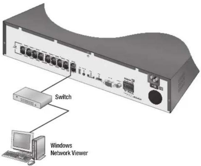
Remote Monitoring function by Windows Network Viewer
• Live monitoring of the network camera
• Installation Wizard Function(Quick Setup)
Package Contents
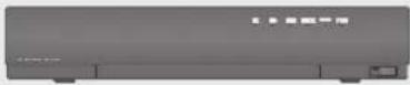
Please unwrap the product, and place the product on a flat place or in the place to be installed. Please check the following contents are included in addition to the main unit.
SRN-473S
■ Two additional screws are provided to install an HDD for models that come without an HDD installed.
SRN-873S
NVR Mouse
Power Cable
Network Viewer Software /User Manual CD
Remote Control /Remote Control Battery (AAA)
User Manual or Quick Manual Bracket rack Bracket mounting screws
Terminal block
SRN-1673S
NVR Mouse
Power Cable
Network Viewer Software /User Manual CD
Remote Control /Remote Control Battery (AAA)
User Manual or Quick Manual Bracket rack Bracket mounting screws
Terminal block
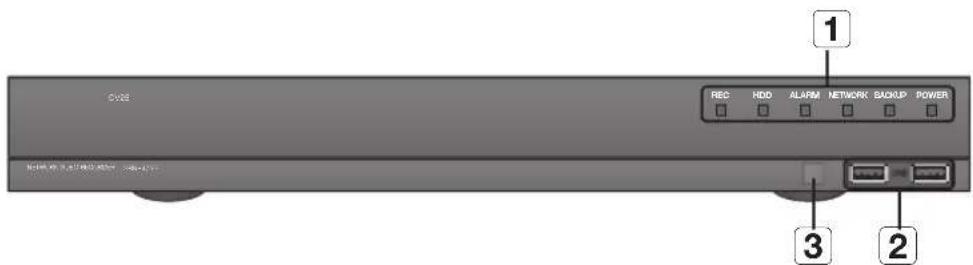
PART NAMES AND FUNCTIONS (FRONT)
SRN-473S
SRN-873S
SRN-1673S
Part Names Functions
1
LED Indicator
REC: Lights on when recording is in progress.
HDD: Displays the normal access to HDD.LED turns on when accessing the hard disk.
ALARM: Lights on when an event occurs.
NETWORK: Displays both network connection and data transfer status.
BACKUP: Displays when Backup is in progress.
POWER: Shows the power ON/OFF status.
2
USB
Connects the USB devices.
3
Remote Reception System
Receive the signal from the remote control.
SRN-473S
SRN-873S
SRN-1673S
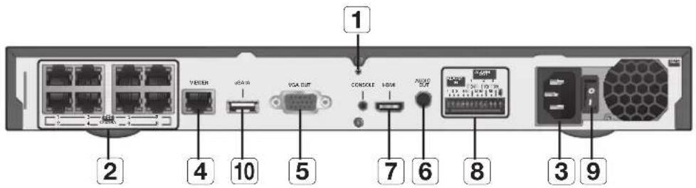
Part Names Functions
1
Ground connection
A terminal to connect a separate ground cable.■ Make sure to add a ground cable in order to use the equipment safely.
2
PoE (CAMERA)
Power supply port to connect to a camera.
3
Power
Terminal to connect power to.
4
VIEWER
Port used to send video to the web viewer.
SWITCH
Port connected to a camera, and you can access the camera's web viewer to setup detailed camera settings.
5
VGA OUT
VGA Video Signal Output Port.
6
AUDIO OUT
Audio Signal Output Port (RCA jack).
7
HDMI
HDMI connector port.
8
ALARM
- ALARM IN : Alarm input ports.SRN-473S : 1~2 CHSRN-873S : 1~4 CHSRN-1673S : 1~8 CH- ALARM OUT : Alarm output ports.SRN-473S : 1CHSRN-873S : 1~3 CHSRN-1673S : 1~4 CH- ALARM RESET : Alarm Reset port.■ Applicable only to the SRN-1673S model.
9
Power Switch
Power on/off switch.
10
eSATA
Ports used for external storage device connections.
11
USB
Connects the USB devices.
■ [CONSOLE] is designed for the service repair purpose only.
Using the Numeric buttons
CHANNEL 1–9 Press each button between 1 to 9.
CHANNEL 10
Press the [+10] button first, then press the 0 button again within 3 seconds.
CHANNEL 11–16
Press the [+10] button first, then press any number between 1 to 6 within 3 seconds.
Changing the Remote Control ID
Remote control's ID and NVR's ID should be matched for proper operation.
Press the [ID] button of the remote control and check the ID displayed on the NVR screen. The factory default ID of the remote control is 00.
Enter 2 digits of your selection in order, while pressing the [ID] button of the remote control.
When ID input is done, press the [ID] button of the remote control again to check the setting.
If you want to change the remote control ID to 08: Press 0 and 8 in order while the [ID] button of the remote control is pressed.
For changing the ID of remote device, refer to "Remote Devices". (Page 85)
Please take note of the followings before using this product.
Do not use the product outdoor.
Do not spill water or liquid in the connection part of the product.
Do not impose the system to excessive shock or force.
Do not pull out the power plug forcefully.
Do not disassemble the product on your own.
Do not exceed the rated input/output range.
Use a certified power cord only.
For the product with an input ground, use a grounded power plug.
CHECKING THE INSTALLATION ENVIRONMENT
This product is a top-notch security device that is equipped with a high-capacity HDD and other key circuit boards.
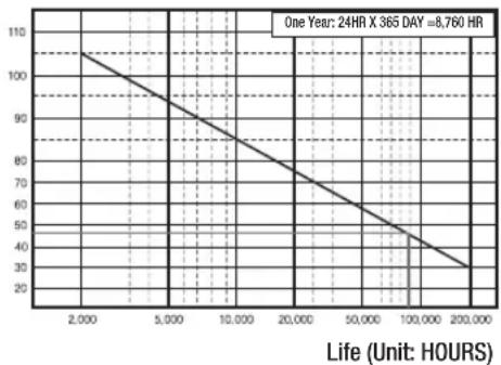
Note that an excessive internal temperature of the product may cause a system failure or a shortened product life (see the right figure). Keep in mind the following instructions before installing the product.
Temperature
Unit: °C
line
| Life (Unit: HOURS) | Value |
|---|---|
| 2,000 | 105 |
| 5,000 | 90 |
| 10,000 | 75 |
| 20,000 | 60 |
| 50,000 | 45 |
| 100,000 | 35 |
| 200,000 | 30 |
One Year: 24HR X 365 DAY = 8,760 HR
[Figure 1]
When mounting the product on a rack, comply with the following instructions.
Please ensure that the rack inside is not sealed.
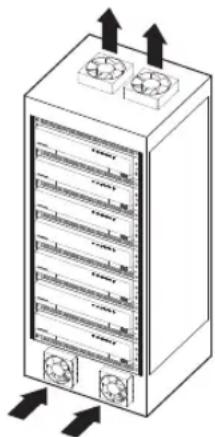
Please ensure the air is circulated through the inlet/outlet as shown in the picture.
If you pile up the prudcts or other rack-mount devices as shown in figure 2, secure room for ventilation or install a vent.
For natural air convection, place the inlet at the bottom of the rack and the outlet on top.
It is strongly recommended that a fan motor is installed at the inlet and the outlet for air circulation. (Please fit a filter at the inlet to screen dust or foreign substances.)
Please maintain the temperature inside the rack or surrounding areas between 0^ C \~ 40^ C ( 32^ F \~ 104^ F) as shown in the figure 1.
Rack Mount Instructions - The following or similar rack-mount instructions are included with the installation instructions :
A) Elevated Operating Ambient - If installed in a closed or multi-unit rack assembly, the operating ambient temperature of the rack environment may be greater than room ambient. Therefore, consideration should be given to installing the equipment in an environment compatible with the maximum ambient temperature (Tma) specified by the manufacturer.
natural_image
Illustration of a server rack with heat exchangers and ventilation fans (no text or symbols)
[Figure 2]
B) Reduced Air Flow - Installation of the equipment in a rack should be such that the amount of air flow required for safe operation of the equipment is not compromised.
C) Mechanical Loading - Mounting of the equipment in the rack should be such that a hazardous condition is not achieved due to uneven mechanical loading.
D) Circuit Overloading - Consideration should be given to the connection of the equipment to the supply circuit and the effect that overloading of the circuits might have on overcurrent protection and supply wiring. Appropriate consideration of equipment nameplate ratings should be used when addressing this concern.
E) Reliable Earthing - Reliable earthing of rack-mounted equipment should be maintained. Particular attention should be given to supply connections other than direct connections to the branch circuit (e.g. use of power strips).
RACK INSTALLATION
Install the Bracket-Rack as shown in the figure, and then fasten the screws on both sides (2 screws on each side).
- Fix the screws not to be loosened by vibrations.
natural_image
3D rendering of a black rectangular electronic device with mounting brackets and connectors (no visible text or symbols)
Cautions when Installing in the Rack
To install multiple NVRs in the rack, make sure to separate the FOOT at the bottom of each NVR.
There are four FOOTs at the bottom of a NVR.
Press the projected parts at both-ends of each "FOOT" and turn it counterclockwise.
natural_image
Pure diagram of a cylindrical object with two arrows pointing outward, no text or symbols present
"FOOT" is separated from the main body when it is turned to the end of fastening groove.
Make sure to unplug the power cord from the wall outlet to prevent possible electric shock, injury or product damage. Please consult your provider for further information on HDD installation since improper installation or settings may damage the product.
■ Number of HDDs supported : SRN-473S : max 1
SRN-873S : max 2
SRN-1673S : max 4 can be added.
■ Make sure to unplug the power cord from the wall outlet before proceeding with the installation.
■ Cautions for data loss (HDD care)
Please pay attention so that the data inside the HDD is not damaged.
Before adding a HDD, please check the compatibility with this product.
HDD is vulnerable to malfunction due to its sensitive nature especially against shock when operating.
Please ensure that the HDD is free from such shock.
We are not liable for any damage to the HDD incurred by user's carelessness or miss use.
■ Cases might cause damage to HDD or recorded data
To minimize the risk of data loss from a damaged HDD, please backup data as often as possible.
If exposed to shock when disassembling or installing, data stored in the hard disk may be damaged.
A sudden power failure or turning off the product while in HDD operation may damage the hard disk drive.
HDD or files stored inside may be damaged if the main body is moved or impacted during the HDD operation.
Cautions when installing a HDD
Do not apply excessive force to the HDD.
Pay attention so as not to lose the disassembly screws or accessories.
If the screws or accessories are not put together correctly, the product may breakdown or not operate properly.
Please check the HDD compatibility before adding a HDD.
- Please contact your nearest dealer to obtain the list of compatible devices.
Installing the HDD
If the installed HDD had been used with other devices, it will be automatically formatted.
How to install an HDD in SRN-473S
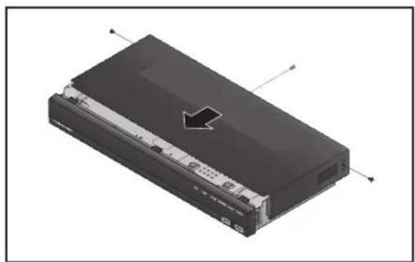
After unscrewing, push back and remove the cover.
natural_image
3D rendering of a black electronic device with ventilation grilles and an arrow pointing to a component (no visible text or symbols)
Loosen a setscrew of the bracket.
natural_image
Isometric view of a device chassis with internal components and an arrow indicating direction (no text or symbols)
Push the bracket in the direction of the arrow on the board and remove it.
natural_image
Exploded view diagram of a computer chassis showing internal components (no text or labels)
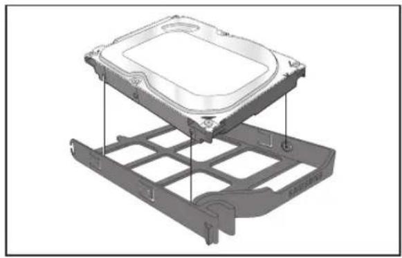
After inserting the HDD into the bracket, tighten the left and right screws to fix it.
natural_image
Exploded view diagram of an electronic device showing internal components and casing (no text or labels)
Locate the bracket with the HDD installed in a groove of the case, push it in the arrow direction and connect a power data port on the board.
natural_image
3D rendering of an open Raspberry Pi with visible internal components and a black arrow pointing to a specific area (no text or symbols)
Tighten a setscrew of the bracket.
natural_image
Isometric view of a device chassis with internal components and an arrow indicating direction (no text or symbols)
Close the cover, and tighten a setscrew in the back.
natural_image
3D rendering of a black rectangular electronic device with ventilation grilles and an arrow indicating a component (no text or symbols visible)
How to install an HDD in SRN-873S
First of all, loosen the screws in the left, right, and back of the case, and remove the cover.
natural_image
3D rendering of a black electronic device with an arrow pointing to its top panel (no text or symbols visible)
Loosen a screw from the HDD bracket and remove the bracket.
■ While applying pressure to both side end grips of the bracket, pull them forward to remove the HDD bracket from the main body.
natural_image
Diagram of hands operating a computer motherboard with a highlighted component (no text or symbols visible)
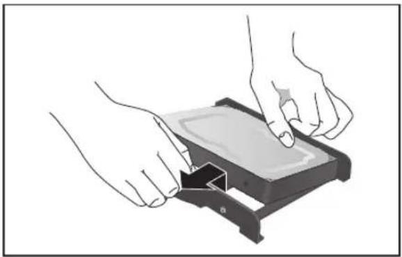
After aligning and inserting one side of the HDD to the bracket, open the other side bracket wide and insert the HDD between them.
- Align a hole in the bracket with a screw hole in the HDD to fix them.
natural_image
Illustration of hands installing or adjusting a device component (no text or symbols visible)
Push the bracket with the HDD installed and tighten the screws to fix it.
natural_image
Illustration of hands operating a computer motherboard with two monitors and a keyboard (no text or symbols visible)
Close the cover and tighten the screws to fix it.
natural_image
3D rendering of a black electronic device with directional arrows indicating orientation (no text or symbols)
How to install an HDD in SRN-1673S
• How to open the front cover and install an HDD
Pull open the front cover.
natural_image
Hand inserting a cable into a black rectangular electronic device (no text or symbols visible)
Open the front cover and check the HDD installation bracket.
■ Release the USB connection before opening the front cover to prevent damage to the USB port.
natural_image
3D rendering of a rectangular electronic component with mounting brackets and internal slots (no text or symbols)
Push the latch to the right and remove the HDD bracket.
Take care not to scratch your hands when removing the HDD bracket.
natural_image
3D rendering of a rectangular electronic device with internal components and a handle, shown without any text or symbols.
Align and insert HDD into the bracket home. After inserting one side, push and insert the other side slightly.
natural_image
3D technical illustration of a mechanical housing assembly with mounting brackets (no text or symbols)
Align the bracket with the HDD installed with the enclosure latch, and push the bracket in the direction of the board.
■ Push it until you hear the latch lock sound. If the HDD is not completely connected, it may be detected.
natural_image
3D rendering of a rectangular electronic device with internal components and a handle, shown without any text or symbols.
Push the front cover upwards and close it.
natural_image
3D rendering of a rectangular electronic device with internal components and mounting base (no text or symbols visible)
• How to exchange an installed HDD
Open a bracket wide in the direction of the arrow and remove the holder from the HDD.
Open the other bracket wide and remove it from the holder.
- The procedure after HDD exchange is the same as the procedure for "Installing the HDD".
natural_image
3D rendering of a hard disk drive housing with mounting holes and mounting points (no text or symbols)
connecting with other device
CONNECTING TO AN EXTERNAL DEVICE
■ The following figures are based on Model SRN-1673S.
- Unrated or improper power source may cause damage to the system. Ensure that you use only the rated power source before pressing the POWER button.
CONNECTING THE USB
On the front of the product, there is a USB port.
USB HDD, memory, or a mouse can be connected to USB ports.
If a USB HDD is connected to the system, recognition and settings are available in "Setup > Device > Storage Device". (Page 83)
The product supports hot plugging function that enables connecting/disconnecting USB devices while in operating the system.
■ If you use the USB device for Backup purposes, format it with FAT32 on PC if it is not formatted on the NVR.
■ Some USB devices may fail to function properly due to compatibility issue, please check the device before using.
- Only USB storage devices that comply with the standards (having a metal cover) are guaranteed for data transfer. In case if the USB device's electric contacts have been worn out, data transfer between the devices may not properly function.
natural_image
Two technical illustrations of USB connectors, one with a circular outline highlighting the internal structure (no text or symbols present)
connecting with other device
CONNECTING THE ALARM INPUT/OUTPUT
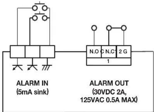
The Alarm In/Out port at the back is composed of the following.
SRN-473S
• ALARM IN 1 \~ 2 : Alarm Input Port
• ALARM OUTI : Alarm Output Port
SRN-873S
• ALARM IN 1 \~ 4 : Alarm Input Port
• ALARM OUT 1 \~ 3 : Alarm Output Port
natural_image
Pure electrical circuit lines without any symbols
ALARM IN (5mA sink)
ALARM OUT (30VDC 2A, 125VAC 0.5A MAX)
connecting with other device
SRN-1673S
• ALARM IN 1 \~ 8 : Alarm Input Port
- ALARM RESET : On receiving an Alarm Reset signal, the system cancels the current Alarm Input and resumes sensing.
• ALARM OUT 1 \~ 4 : Alarm Output Port
ALARM IN (5mA sink)
ALARM OUT
(30VDC 2A, 125VAC 0.5A MAX)
- For more information about network connection, refer to "Network Configuration". (Page 97)
- The following figures are based on Model SRN-1673S.
Network connection via Ethernet (10/100/1000BaseT)
Network connection via router
flowchart
graph TD
    A["Network"] --> B["Brodband router"]
    A --> C["xDSL or Cable Modem"]
    A --> D["DDNS Server (Data Center)"]
    A --> E["Windows Network Viewer"]
connecting with other device
Connecting to Internet through PPPoE
flowchart
graph TD
    A["Windows Network Viewer"] -->|Switch| B["PPPoE MODEM"]
    B -->|Phone(PPPoE) Line| C["Switch"]
    C --> D["Network Camera"]
    C --> E["Network Camera"]
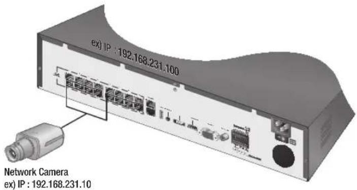
Connecting the network camera
PnP mode
Manual mode
flowchart
graph TD
    A["Network Camera"] --> B["Switch"]
    C["Network Camera"] --> B
    D["Network Camera"] --> B
    E["Network Camera"] --> B
    F["Network Camera"] --> B
    G["Network Camera"] --> B
    H["Network Camera"] --> B
    I["Network Camera"] --> B
    J["Network Camera"] --> B
    K["Network Camera"] --> B
    L["Network Camera"] --> B
    M["Network Camera"] --> B
    N["Network Camera"] --> B
    O["Network Camera"] --> B
    P["Network Camera"] --> B
    Q["Network Camera"] --> B
    R["Network Camera"] --> B
    S["Network Camera"] --> B
    T["Network Camera"] --> B
    U["Network Camera"] --> B
    V["Network Camera"] --> B
    W["Network Camera"] --> B
    X["Network Camera"] --> B
    Y["Network Camera"] --> B
    Z["Network Camera"] --> B
    AA["Network Camera"] --> B
    AB["Network Camera"] --> B
    AC["Network Camera"] --> B
    AD["Network Camera"] --> B
    AE["Network Camera"] --> B
    AF["Network Camera"] --> B
    AG["Network Camera"] --> B
    AH["Network Camera"] --> B
    AI["Network Camera"] --> B
    AJ["Network Camera"] --> B
    AK["Network Camera"] --> B
    AL["Network Camera"] --> B
    AM["Network Camera"] --> B
    AN["Network Camera"] --> B
    AO["Network Camera"] --> B
    AP["Network Camera"] --> B
    AQ["Network Camera"] --> B
    AR["Network Camera"] --> B
    AS["Network Camera"] --> B
    AT["Network Camera"] --> B
    AU["Network Camera"] --> B
    AV["Network Camera"] --> B
    AW["Network Camera"] --> B
    AX["Network Camera"] --> B
    AY["ex) IP : 192.168.1.100"]
GETTING STARTED
Starting the system
Connect the power cable of the NVR to the wall outlet.
natural_image
Desktop icons including a desktop, tablet, and monitor on a dark background (no text or symbols)
You will see the initialization screen.
The initialization process will last about 2 minute.
If a new HDD is installed, the initialization process may take longer.
natural_image
Pure desktop icons including monitor, keyboard, and mouse on dark background (no text or symbols)
The live screen appears with a beep.
As shown below, proceed through each step of the .
In the screen, select the language and press the button.
In the screen, set the password and press .
If you click < ☐ >, a basic guide for password setup is displayed.
In the screen, set the network access method and the access environment. To use a simple intranet, click .
• Network 1 (Camera) : Connects to the camera and receives the video feed from the camera
- Network 2 (Viewer): This is a port for transmitting an image to the webviewer.
• Network 1 / Network 2 Setup
- IP Type : Choose the network connection method.
- IP Address, Subnet Mask, Gateway, DNS
If the LAN cable is not connected to the port, the setting button will not be activated for use. Check the LAN cable connection.
The built-in DHCP Server in NVR will turn on automatically at stage 3. At this stage, using the existing DHCP server in the same network may cause a problem, as two DHCP servers would be simultaneously operating.
■ For more details on network settings, refer to the user manual.
After setting the date/time settings in the screen, click on the button to launch the setting completion window.
In the setting completion window, click on the button to finish camera setting and launch the camera registration screen.
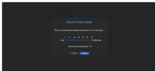
If there are 16 or less cameras searched, it will be automatically registered and the camera information(fps, days of recording) will be displayed.
- If there are 16 or less cameras searched
The searched camera will be automatically registered and the initial recording value will be displayed.
In the camera registration window, click the button to modify the recording settings automatically set.
- If there are more than 16 cameras searched
Select a camera to register and click the button. Once camera registration is finished, proceed in the same steps as after auto registration.
Shutting Down the System
Press the [POWER] button for your remote controller or select in the live screen menu.
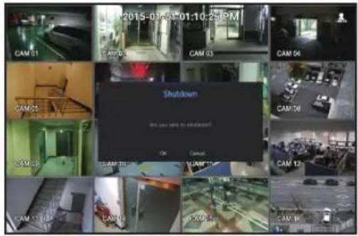
The "Shutdown" confirmation pop-up window will appear.
Using the directional button on your remote control, select and press the [ENTER] button or click on . The system will shut down.
Only the user with the "shutdown" permission can shut down the system.
■ For the permission management, refer to "User > Setting Permissions". (Page 63)
Login
If you want to use the NVR menu, you need to login as a user with the privileges to access it.
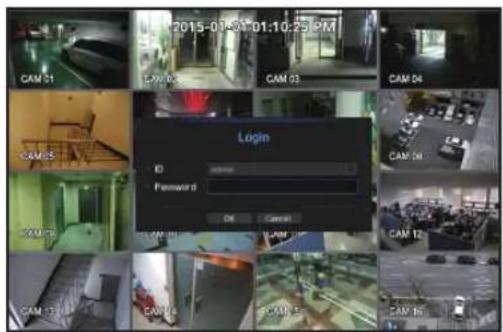
In the live mode screen, right click the mouse button or press the [MENU] button on your remote control. You will see the context menu on the screen as shown.
Select .
The login dialog appears.
Even if you press the menu button that requires a login with the remote control, the login screen will appear.
- The first administrator ID is "admin" and the password must be set in the Installation Wizard.
- Set password for your wireless network if you use the product with a wireless router. Being not protected with password or using the default wireless router password may expose your video data to po
Please change your password every three months to safely protect personal information and to prevent the damage of the information theft. Please, take note that it's a user's responsibility for the security and any other problems caused by mismanaging a password.
■ To change access privileges, refer to "User > Setting Permissions". (Page 63)
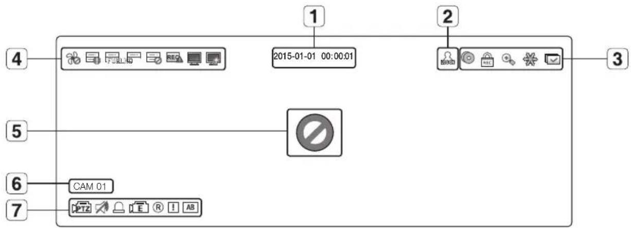
Icons on the Live Screen
You can check the status or operation of the NVR with the icons on the live screen.
Name Description
1
Current Date, Time
Displays the current time and date.
2
Login Information
When you are logged in, the "LOG ON" icon will be displayed.
3
Screen Mode
[YZX]
It is displayed when there is ongoing backup in the live condition.
If access to the recording canceling menu is restricted, then it is only displayed when there is ongoing manual recording.▪ Only a user with the right to cancel recording can do so.
It is displayed when the magnifying function is in operation.
This icon is displayed when you press the Freeze button.
[2H34]
It is displayed when all the channels are switched at the set time interval.
4
System Operation
[S4K4]
It is displayed when there is a problem with the fan.
It is displayed when the recording data cannot be received properly due to a device problem.
Displayed if the HDD is full and the NVR has an insufficient space to record.
Displayed if no HDD is installed or the existing HDD should be replaced.
Displayed if the HDD needs a technical examination.
4
System Operation
[5x36]
It is displayed when the max permitted amount of data for each channel is exceeded.
[X676]
It is displayed when the network is overloaded.■ It occurs when the max receiving allowance is exceeded, causing an overload to the CPU. It will disappear if you modify the camera settings or delete a camera to reduce the performance burden.
It is displayed when there is firmware to update the server.
5
Video Input Status
Displayed if no input is entered in the condition that the camera is set to.
WISENET
Displayed if no permission to live view is granted.
If a camera is, or if no camera is registered, or it is inmode, nothing will be displayed on the screen.If the camera is set to, the video will not be displayed but the OSD menus will be displayed.
6
Camera Title / Channel
Display the camera title and channel number.
7
Camera Operation
This icon is displayed for a channel that a PTZ-featuring camera is connected to.
Displays AUDIO ON/MUTE. Not displayed in video mode if deactivated.
[###]
If the sensor is set to, the input signal will be displayed on the screen of the connected channel.
[###]
This icon is displayed when Motion Detection is set toand a camera motion or camera event occurs.
[###]
It displays the status of general/event/scheduled recording.
[###]
It is displayed when it fails to decode all the frames due to limited decoding performance and in this case only the I-Frame is decoded.
[###]
This is displayed when a POS (text) event occurs.
Error Information
If the built-in HDD is not connected, the "NO HDD" icon (☐) will be displayed in the top left corner. In this case, make sure you contact the service center for assistance as this may cause a failure of recording, playback or backup.
If the cooling fan does not work properly or has a problem, the window will appear and the fan error icon ( ) will be displayed on the top left corner.
In this case, check to see if the internal fan works.
As a fan error can shorten the product life, make sure you contact the service center for assistance.
If you see the fan error icon or NO HDD, HDD FAIL icons on the screen, contact the service center for more details.
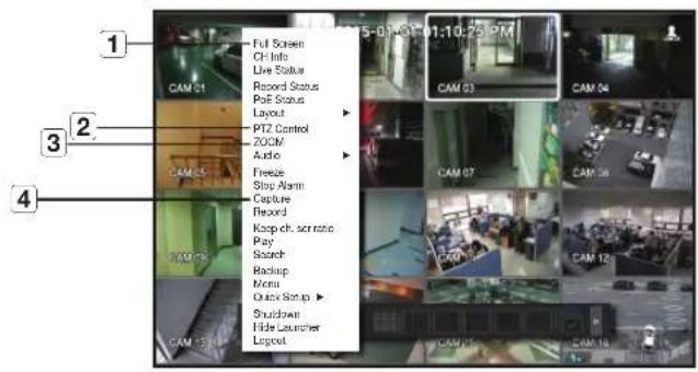
Live Screen Menu
Beside the functional buttons for your remote control, in the live screen mode, you can right click with the mouse button or press the [MENU] button on your remote control to launch the live screen menu from where you can access each menu from.
The context menu differs depending on the state of Log in/out, split mode, and NVR operation status.
Live view, backup, recording, stopping recording, search, PTZ, remote alarm output, and termination menus can be restricted in use depending on user privilege settings.
< Single Mode Menu >
< Split Mode Menu >
Single Mode Menu
The single mode menu is available only in Single Mode.
If the menu is displayed as in the single screen, it is displayed as a in the menu where only one channel is selected in the split screen.
< Single Mode Menu >
< One channel selection menu in the split screen >
Menu Description
1
Full Screen
Select and click a desired channel in Split mode to switch to the full screen of the selected channel.
2
PTZ Control
Accesses the PTZ Control menu. The PTZ menu will be active on the Live screen after you select a single channel. (Page 56)
3
ZOOM
You can enlarge the selected screen. (Page 49)
4
Capture Captures the screen of the selected channel.
Split Mode Menu
In Live split mode, right-click to display this context menu as shown.
The context sensitive menu in split mode differs, depending on the login/logout status.
Menu Description
1
Screen Mode
Select a screen mode for the Live screen.Refer to “Live screen mode”. (Page 45)
2
CH Info
It displays the camera connection information for each channel.Refer to the “Channel Information”. (Page 47)
3
Live Status
Shows the live status of connected camera to each channel.Refer to “Live Status”. (Page 48)
4
Record Status
Shows the record status of each channel.Refer to “Record Status”. (Page 48)
5
PoE Status
Set the PoE status in each channel.Refer to the “PoE Status”. (Page 50)
6
Layout
Set the layout of each channel.Refer to “Layout”. (Page 51)
7
Audio On/Off
Turns ON/MUTE the sound of the selected channel.Refer to “Audio ON/OFF”. (Page 52)
8
Freeze
Stop playing the video temporarily. Refer to “Freeze”. (Page 52)
9
Stop Alarm
Stop the alarm output, deactivate the event icon and release the auto sequencing.Refer to "Event Monitoring”. (Page 53)
10
Record/Stop Starts/stops the standard recording.
11
Keep full scr ratio/Keep ch. scr ratio
Channel screen ratio is changed.Refer to "Maintain the Screen Ratio". (Page 54)
12
Play
Refer to "Search & Play > Play". (Page 113)
13
Search
Refer to "Search & Play > Search". (Page 109)
14
Backup
Searches for a backup device and runs backup for each channel or schedule backup later at a more preferable time.
15
Menu
Enter the main menu. Refer to the menu settings. (Page 59)
16
Quick Setup
The "Camera Register" & "Recording Setup" screen will immediately appear.
17
Shutdown
The system shutdown dialog will appear.
18
Show/Hide Launcher
Shows or hides the launcher. Refer to "View the Launcher Menu". (Page 44)
19
Login/Logout You can log in or out.
View the Launcher Menu
The Launcher menu appears on the bottom of the live screen.
Select in the context menu of the Live screen.
Move the cursor to the bottom and click a desired item in the Launcher menu.
■If no input is entered for 10 seconds, the menu will disappear.
■The Launcher menu can be accessed only by using the mouse.
■SRN-473S only supports full screen, 4-split screen, and automatic switchover screen.
■SRN-873S does not support 13/16-split screen.
Menu Description
1
Layout Select the layout to be displayed on the screen.
2
Layout Setup You can set, change or delete the new layout of each channel.
3
Screen Mode
Displays a list of split modes available in a bar type.The current screen mode will be displayed grey.
4
Menu Expansion Button
Click to display the hidden menu to the right.
5
Backup
Searches for a backup device and runs backup of each channel or schedule it for later at a more desirable time.
6
Zoom Enlarges the selected area. This is available only in Single Live mode.
7
PTZ
If the network camera connected to the selected channel supports the PTZ operations, this will run the PTZ control launcher. This is active only in Live single mode.
8
Alarm Stops the alarm if it's activated.
9
Freeze Freezes the Live screen temporarily.
10
Capture Captures the screen of the selected channel.
11
Text Text output is ON or OFF.
12
Play Enters Play mode if a file to play exist, and if not, enters Search mode.
13
Record
Start/End recording the Live screen.
16 live videos are displayed in a single screen, 6 kinds of split screens, and an automatic switchover screen.
Method for displaying screen mode
If you want to change the split mode, select a screen mode suggested in the launcher menu or right click with the mouse button and select a split mode in the screen mode menu.
Press the [MODE] button on your remote controller to change it in the order suggested in the launcher menu.
■ SRN-473S only supports full screen, 4-split screen, and automatic switchover screen.
8-split mode 13-split mode Auto Sequence Single mode
Auto screen switching
SRN-1673S can display 16 live videos sequentially in full screen, 4-split screen, and 9-split screen.
flowchart
graph TD
    A["Layer 1"] --> B["Layer 2"]
    B --> C["Layer 3"]
    C --> D["Layer 4"]
    D --> E["Layer 5"]
    E --> F["Layer 6"]
    F --> G["Layer 7"]
    G --> H["Layer 8"]
    H --> I["Layer 9"]
    I --> J["Layer 10"]
    J --> K["Layer 11"]
    K --> L["Layer 12"]
    L --> M["Layer 13"]
    M --> N["Layer 14"]
    N --> O["Layer 15"]
    O --> P["Layer 16"]
Single mode
flowchart
graph TD
    A["CHI CHI"] --> B["13-16"]
    C["CHI CHI"] --> D["9-12"]
    E["1-4"] --> F["5-8"]
    B --> G["✓"]
    D --> H["✓"]
4-split mode
9-split mode
In a split mode, If you have set in "Device >Monitor", Auto Sequence will be conducted at the set interval. (Page 85)
- When a channel is changed, a video may be displayed delayed due to the network environment.
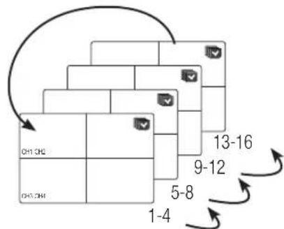
Manually change the screen
Press the left/right button on the front panel or the remote control, or click the arrow <◀/▶> key to move to the next split mode.
- If pressing the right [▶] button in 9-split mode:
9-split (CH 1\~9) mode → 9-split (CH 10\~16) mode → Auto Sequence
- If pressing the right [▶] button in 4-split mode:
Channel (CH 1\~4) → Channel (CH 5\~8) → Channel (CH 9\~12) → Channel (CH 13\~16) → Auto Sequence
flowchart
graph LR
    A["CH1 CH2\nCH3 CH4"] --> B["CH5 CH8\nCH7 CH8"]
    B --> C["CH9 CH10\nCH11 CH12"]
    C --> D["CH13 CH14\nCH15 CH16"]
flowchart
graph TD
    A["Start"] --> B["Segment 1"]
    B --> C["Segment 2"]
    C --> D["Segment 3"]
    D --> E["Segment 4"]
    E --> F["Segment 5"]
    F --> G["Segment 6"]
    G --> H["Segment 7"]
    H --> I["Segment 8"]
    I --> J["Segment 9"]
    J --> K["Segment 10"]
    K --> L["Segment 11"]
    L --> M["Segment 12"]
    M --> N["Segment 13"]
    N --> O["End"]
    style A fill:#f9f,stroke:#333
    style O fill:#f9f,stroke:#333
Channel Setting
You can display the channel in a desired area of a split screen.
Place the cursor over the camera name of each channel to display the <▼> key to the right on the screen.
Click a camera name to display a channel list where you can select a different channel.
Select a desired channel and click it.
The selected channel is displayed in the screen. If you want to change the channel location, you can place your mouse cursor over the desired location.
Ex: If you want to change channel 1 area to channel 7 area.
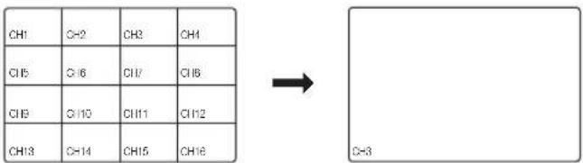
Switching to Single Mode
Double click with the mouse button on the desired channel in the split screen to switch the screen to the single screen.
Press the channel number button on the remote control to switch to single screen.
Refer to "Remote Controller > Using the Number Button". (Page 16)
Ex: With your mouse, double click on channel 3 or press the number 3 on the remote control.
Channel information
Select the in the live screen menu to check the status of camera connection to each channel.
Live Status
Select from the live screen menu to display status and transfer information of connected camera to each channel.
- Model : Displays the camera model name connected to each channel.
- Status : Displays the status of camera connection set to each channel.
- IP Address : Displays the IP address of a camera set to each channel.
- Codec : Displays the live profile codec information for a camera set to each channel.
- Resolution : Displays the live profile resolution of a camera set to each channel.
- Frame Rate : Displays the live profile transmission rate for a camera set to each channel.
• Quality : Displays the live profile transmission quality of a camera set to each channel.
Record Status
Select from the live screen menu to display camera profile, input/recording frame rates, input/limit/recording bps of each channel.
- Total Bitrate (Record/Max) : Record bitrate shows the amount of actual data recording while Total bitrate shows the maximum data transfer allowed by the NVR.
- Profile : Shows the video profile configured to each channel.
- Frame (fps) : Show the input/record frames per second for each channel.
- Bitrate (bps)
- Limit / Input / Record : Shows the amount of limit/input/recording data for each channel.
- Input / Limit : Shows the data ratio of actual data transferred from the camera and allowed maximum defined by user.
- current : Shows the recording status information of currently transferred data.
- MAX: Shows recording information of the most biggest recording data out of configured standard and event recordings.
• : Reloads the recording information.
- Record Setup: The menu screen will switch to the record setting screen.
The warning message on the list's bottom means the NVR replaced the selected recording profile with other available profile, since the selected one does not produce video data which prohibits screen saving. If the screen displays video, it automatically resets to the selected profile and its name turns to yellow in the list.
If Key Frame recording exceeds the allowed data amount specified by limit bitrate, a popup alert and icon appear on the screen.
The limited recording alert popup does not repeat after displaying once unless camera or recording settings are changed; it may appear again if settings were changed to notify such status.
If you want to set the alert popup not to appear, change your setting of not to display a message popup. For further information on bitrate limit of recording data, refer to "Record Setting". (Page 90)
ZOOM
This is activated only in Live Single mode.
After selecting a single screen, if you use the Magnify function, the selected area will be magnified by 2.
In the live screen menu, select .
Press the [ZOOM] button on your remote control or click < ✕> on the launcher menu.
The Magnify icon in the middle of the screen will be displayed.
You can use the remote control's directional key(▲▼◀▶) or drag with the mouse to set the area of magnification.
Press the [ENTER] button or double click with the mouse to magnify the selected area by two times.
In the magnified screen, you can drag with the mouse or use the remote control's navigational key (▲▼◀▶) to move the magnified area.
In the live screen menu, select .
Press the [ZOOM] button on your remote control or click < 🔒> on the launcher menu to cancel the magnification function.
natural_image
Side-by-side comparison of two cars in a parking garage, one showing red and white interior, the other showing white exterior with 'CAM 01' watermark (no visible text on car or signage)
POE STATUS
In the live screen, you can see the PoE status of each port.
1. Select the .
PoE status view window is displayed.
- Consumption(W) : Displays the power consumption in PoE.
- 0 : No device is connected to the port or a device is using its own power supply.
-- : Trouble in the port (More detailed trouble information can be displayed in additional information.)
■Overall PoE power specifications are as follows: SRN-1673S(16 ports) is 200W, SRN-873S(8 ports) is 100W, and SRN-473S(4 ports) is 50W.
If a single port exceeds 36W, or the power to all ports exceeds the overall PoE power specifications, the power to ports will be shut off sequentially.
- PoE: Turns on/off the power supply to the camera.
If checked, it means the power supply is On; if not checked, it means it is Off.
• Additional information : If there is a problem in the power supply, it is explained here.
Power supply problems include excessive power (class 1 to 4) and voltage errors.
- Total PoE power consumption: Display the sum of power consumption for all the ports.
Press to move to the previous screen.
Noise level according to PoE power consumption
Model Noise Level [dB] PoE Power
SRN-1673S
50 196W
48 154W
47 138W
In the live screen, you can set the layout for each channel.
Setting Up the Live Layout
This section outlines how to select a series of channels based on their purpose/accessibility and monitor them in a single layout.
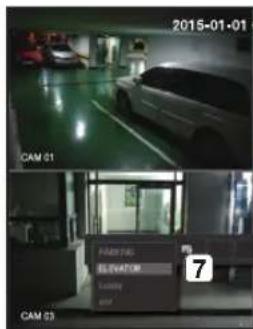
Example) Layout "Lobby" - Lobby camera 1, Lobby camera 2, Front entrance camera 2
Layout "VIP" - Directors' meeting room 1, Directors' meeting room 2, Directors' lounge 1, Corridor camera on the 7th floor
natural_image
Interior view of a building hallway with glass doors and ceiling-mounted equipment (no visible text or symbols)
To create a new layout, follow these steps:
① Open the channel layout setup menu.
2 Click .
③ Enter a name for the selected channels (e.g., ELEVATOR).
4 Select the channels that you want to add to the layout (e.g., 2, 7, 10, 15).
5 Choose a split mode to apply (e.g., 4-way split).
6 Click .
7 Choose a layout to view it on the screen (e.g., change to ELEVATOR).
Select the < IRO>.
The layout setting screen will appear.
New : You can set the new layout.
Rename: You can make changes to the selected layout. When the layout is changed, the channel order is initialized.
- Delete: You can delete the selected layout.
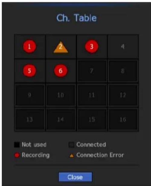
- Ch. Table: You can select channels in the table to be registered in, or removed from the layout.
- Channel List: You can select channels in the list to be registered in, or removed from the layout.
Press the button and enter the name of layout to add.
In the or , click and select the channel to be displayed on the layout screen.
Click on to save the selected layout.
■ The layout for each user is saved separately.
AUDIO ON/OFF
You can turn the sound on/off corresponding to the channel in Live mode.
AUDIO ON/OFF in Single mode
In the screen, click on the audio icon (播放) or in the remote control, press the [AUDIO] button to turn it on/off.
If there is no audio output even if output is activated, check whether the connected network camera supports audio and audio settings.
The sound icon can be displayed if the sound signal fails to output from noise.
- Only the channel where
FREEZE
This is available only in Live mode, this pauses playing the Live image temporarily.
Press the [FREEZE] button on your remote control or click < 📄> in launcher mode.
Video playing is paused.
Press the [FREEZE] button on your remote control or click < 📄> in launcher mode.
Pause is canceled. Playing is resumed.
This will display the channel in sync with a specific event (Sensor/Motion/Video Loss) if it occurs.
In "Monitor > Event Display", set the event monitoring to ON/OFF and specify the event display time. (Page 85)
- If multiple events occur simultaneously, the screen will switch to a split mode.
2\~4 events : 4-split mode
5\~9 events : 9-split mode
10\~16 events : 16-split mode
- If the second event occurs within the set time of , the first event will last until the second one is terminated.
Ex : If you set to 5 seconds, and only one event occurs in CH 1.
Event occurrence 5 seconds
Ex : If you set to 5 seconds, and the second event occurs in CH 2 within the set time after the first event occurred in CH 1.
Event occurrence 4 seconds 9 seconds
flowchart
graph TD
    A["CH1"] --> B["Stop alarm"]
    C["CH1 CH2"] --> B
    B --> D["Stop alarm"]
Press the [ALARM] button or select to initialize the alarm output status and cancel the event function.
If an alarm is output with the pre-event and post-event times specified together with the event recording settings, the event recording will perform according to the specified recording type (pre event or post event).
In case of continuous events such as motion detection, switching to another split mode display may not immediate if concatenating events follow, even when you stopped alarm of the event.
■ The video may be delayed depending on the network condition.
The event output can be delayed as the transfer of the alarm event from the network camera takes time.
The screen ratio for a live video can be changed.
Maintain a screen ratio for all channels
Video screen ratio for all channels can be changed in live split screen mode.
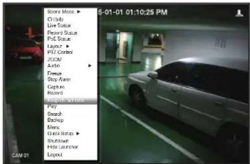
Select from the live screen menu. The screen ratio for all channels will be changed.
If you want to go back to the previous screen ratio, check the menu option for .
Maintain a channel screen ratio
If you select a channel from a live single screen or split screen, you can change its video screen ratio.
Select from the live screen menu. The screen ratio of a specified channel will be changed.
If you want to go back to a previous screen ratio, select again.
natural_image
Interior view of a car garage with two parked cars, one on the floor and another on the wall (no visible text or symbols)
Change text output
The NVR can display text on a live screen when a text device is set.
Select text output
This is executable when a text device is connected.
How to turn the text output off: Select "OFF" from the text list.
How to display on other devices differently from the preset device: Select a device to display from the text list.
PTZ CONTROL
With this NVR, you can configure the settings of a PTZ camera as well as commercial cameras in the market to your preference.
PTZ device
This is active only if a channel that a PTZ camera is connected to is selected.
Getting started with PTZ operations
The PTZ camera will be activated only if the channel of the PTZ camera is selected, which can be performed in the following way:
natural_image
Interior view of a parking garage with parked cars and green flooring (no visible text or symbols)
Using the remote control : Press the [PTZ] button on your remote control.
Using the launcher menu: Click < img> from the launcher menu of the Live screen.
Using the Live screen menu : Select in the context menu of the Live screen.
Using the icons on the Live screen : Simply click the > icon on the Live screen.
This is available only if a PTZ camera is connected and the icon is displayed on the screen.
Even if the connected network camera does not support the PTZ operations, you can configure the PTZ control settings (if possible) by installing the PTZ driver (physical device).
It only supports a network camera with Hanwha Techwin's PTZ function and a camera registered in the ONVIF.
Using the PTZ camera
You can use a single PTZ camera to perform the Pan, Tilt and Zoom operations to monitor multiple places, and configure the custom settings of the presets in a desired mode.
Open the menu.
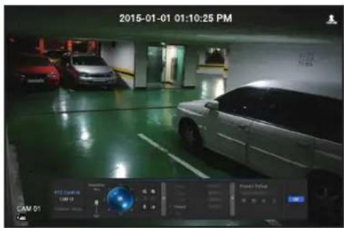
The icon in the left bottom of the screen will turn yellow, indicating that the system accesses "PTZ Control" mode. You will see the "PTZ Control" launcher menu.
- The PTZ working (active) mark can be active even if the PTZ operation is not available in normal mode. So ensure that you have completed the PTZ settings before proceeding.
Adjust the camera recording location by using the PTZ ball in the launcher menu or press the left/right (▲▼◀▶) button on your remote control to move the camera recording location.
- Sensitivity: Adjust sensitivity for Pan, Tilt controls.
- PTZ Wheel : Click a near area from the center to move the camera lens slowly; clicking a far area will move it fast.
If clicking and holding the mouse in the left will turn the camera counterclockwise; if clicking and holding the mouse in the right will move the camera lens clockwise.
- Zoom : Activate the Zoom operation of the PTZ camera.
- Iris: Adjust the amount of light incoming to the camera.
- Focus: You can adjust the focus manually.
- Swing : Swing is a monitoring function that moves between two preset points and enables you to trace the motion.
- Group: The group function enables you to group various presets before calling them in sequence.
- Trace : Tracking remembers the trace of movements that you instructed and reproduces it for your reference.
- Tour : Monitor all the groups created by a user in turn.
■ Some cameras may differ in the menu title and operation with regard to Swing, Group, Tour and Trace.
Even if the network camera supports the PTZ operations by default, the PTZ control can be enabled only if the applicable menu is active in the launcher menu.
Preset
Preset is a specific position remembered by the PTZ camera. You can use the Preset function to define up to 255 presets for a single PTZ camera.
To add a preset
Check the preset checkbox.
Select < □>.
The virtual keyboard will appear on the screen. Use it to provide the preset name.
■ Refer to "Using Virtual Keyboard". (Page 61)
• : You can change the preset settings to your preference.
• : Delete a selected preset.
• : Delete all the existing preset settings.
- You can add up to 255 presets, which is the max count supported by the NVR.
If you replace a camera that saves your preset settings with a different one, you must configure the preset settings again.
Select .
The preset setting will be saved in the provided name.
If you want to change or delete the preset name
Check the preset checkbox and select a preset to change or delete.
If you selected < ☐ >, enter the desired name and press OK.
If you selected < ☐ >, press OK to delete it.
• : Delete all the existing preset settings.
If you delete the entire presets, the default presets specified in the network camera can be deleted accordingly.
You can setup the system, devices, and options for recording, event and network.
SYSTEM SETUP
You can setup Date/Time/Language, User, System Properties and Log.
Date/Time/Language
Setting the Date/Time/Language
You can check and setup the current Date/Time and time related properties, as well as the language used for the interface on the screen.
[MENU] [ENTER] ▼
Other manuals Hanwha
Discover other manuals and user guides for the brand Hanwha
💬 Hi! I'm your manual assistant.I know your Hanwha SRN-473SP.
How can I help you? (use, settings, error codes, maintenance, explaining a step from the manual, etc.)💡 Examples :
• How do I use it ?
• Error code E3 ?
• How do I clean it ?






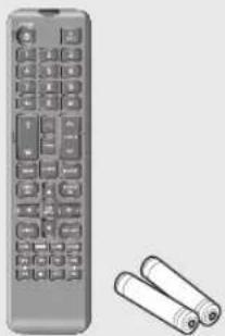









![POWER Displays the Exit pop up screen. NUMBER [0~+10] Used as the numeric input keys, or displays a single channel. PTZ Displays or ends PTZ. T/W Zooms in or out. SEARCH Displays the search menu. MODE Changes the screen mode. MENU Display the live screen menu. PRESET Displays the Preset Setup. FREEZE Freezes the screen temporarily. ZOOM Runs the digital zoom (x2) function. Skip Backward (by unit time), Slow Rewind, Slow Forward, Skip Forward (by unit time) REC Starts or ends the live recording. ID Sets the ID of the system. Select 2 digits from 0 - 9 while pressing the ID Key. SCROLL ∧ V Moves the menu scroll. VIEW Runs the View function in the PTZ mode. BACKUP Displays the Backup Menu. RETURN Returns to the previous screen. Up/Down/Left/Right(▲▼◄►)/ENTER Moves the cursor up/down/left/right, and runs the Select Menu. REC LOCK Selects the recording lock function. AUDIO Turns Audio on/off. ALARM Cancels the Alarm. Move Frame While paused, moves to the previous/next frame. FR, STOP, PLAY/PAUSE, FF](/content/2026/05/1006307/images/fcd6a7055a073e0fa6492bd82ba1f3df150d41772bf8bde3da1ece55b68668f1.jpg)