
DP-V2410 - Projector CANON - Free user manual and instructions
Find the device manual for free DP-V2410 CANON in PDF.


| Product Type | Video Projector |
| Brand | Canon |
| Model | DP-V2410 |
| Resolution | 4K UHD (3840 x 2160) |
| Brightness | 2000 lumens |
| Contrast Ratio | 100,000:1 |
| Light Source | Laser Phosphor |
| Lens | Fixed, manual focus |
| Projection Size | 30 - 300 inches |
| Connectivity | HDMI x2, DisplayPort, USB, Ethernet |
| Dimensions (W x H x D) | 300 x 120 x 300 mm (approx.) |
| Weight | 5.5 kg (approx.) |
| Power Consumption | 300W (typical) |
| Power Supply | AC 100-240V, 50/60Hz |
| Main Functions | 4K upscaling, HDR10, HLG, geometric correction |
| Cleaning | Use a soft, dry cloth; avoid solvents |
| Security | Kensington lock slot |
| Spare Parts | Replacement lamp, air filters |
Frequently Asked Questions - DP-V2410 CANON
User questions about DP-V2410 CANON
0 question about this device. Answer the ones you know or ask your own.
Ask a new question about this device
Download the instructions for your Projector in PDF format for free! Find your manual DP-V2410 - CANON and take your electronic device back in hand. On this page are published all the documents necessary for the use of your device. DP-V2410 by CANON.
USER MANUAL DP-V2410 CANON
- Before use, be sure to read this guide, including the safety and handling precautions.
- Reading this guide will help you learn to use the video display properly.
- Store this guide safely so that you can use it in the future.
Table of Content
Introduction 4
About this manual 4
Trademarks 4
Supplied Accessories....4
Safety Precautions 5
Handling Precautions....6
Features......8
Nomenclature 9
Installation/Connection 11
How to Carry the Main Unit 11
Procedures to attach the protection panel.... 11
Procedures to attach/detach stands.... 12
Preventing from Tipping 13
Mounting the Main Unit on a Stand or Wall.... 14
Connecting the Main Unit to Input Devices.... 15
Turning on the Power 17
Turning on the Power of the Main Unit.... 17
Operating the Video Display.... 18
Operating the jog dial 18
Basic operations to use the OSD menu.... 18
Adjusting Image Quality While Viewing the Entire Image 20
Temporarily Saving Parameters (Anchor Point Setting).... 21
Enlarging the display (Zoom function) 21
Changing Image Quality Automatically According to Input Signal 22
Adjust image quality on left/right side of screen (image comparison mode)....23
Calibration without a PC 23
Export/Import 25
Set Date/Time 27
Inputting Characters....28
Using the Function (F) Buttons 28
Using the Channel (CH) Button....30
Checking Signal Information and Status of the Main Unit.... 31
Operating the video display using an external device [LAN terminal] 32
Operating the video display using an external device [USB terminal: Wi-Fi connection].... 33
Use a web browser to remotely operate the video display 35
OSD Menu....38
OSD Menu Index....38
Adjustment 45
Channel Settings....60
Display Settings....66
Audio Settings....70
Marker Settings 71
Function Settings 76
Picture Function Settings....89
Network/IMD Settings 93
System Settings 95
Signal Information....101
System Information 101
Main specifications/Performance.... 102
Dimensions 104
Appendix 105
Supported Signal Format 105
Image/Frame Display.... 119
Error Messages 122
Troubleshooting....125
Software Used in This Product.... 127
Index....132
Thank you for purchasing the Video Display DP-V2410.
The On Screen Display (thereafter referred to OSD) default language setting is English. To change the OSD menu language setting, please refer to p. 95.
About this manual
Some of the illustration used in the manual have been simplified for clarity.
Conventions used in this manual
: Indicates a reference page.
Note: Indicates a note.
i Reference: Indicates reference information.
CAUTION: Indicates an item you must observe.
Trademarks
- HDMI, HDMI logo, and High-Definition Multimedia Interface are trademarks or registered trademarks of HDMI Licensing Administrator, Inc. in the U.S. and other countries.
- VESA is a registered trademark or trademark of Video Electronics Standards Association in the U.S. and other countries.
• Wi-Fi, WPA, and WPA2 are registered trademarks of the Wi-Fi Alliance.
• Apple and Safari are trademarks of Apple Inc. registered in the United States and other countries.
• Google and Google Chrome are trademarks or registered trademarks of Google LLC. - Other product and company names herein are trademarks or registered trademarks of their respective owners.
Supplied Accessories
The following items are supplied with this product. Please check before using.
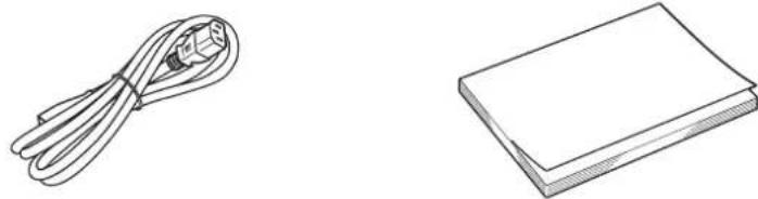
AC Power Cord HT-21 DP-V2410 Instruction Manual
(this document)
For the customers in the U.S.A.
This equipment has been tested and found to comply with the limits for a Class A digital device, pursuant to Part 15 of the FCC Rules.
These limits are designed to provide reasonable protection against harmful interference when the equipment is operated in a commercial environment. This equipment generates, uses, and can radiate radio frequency energy and, if not installed and used in accordance with the instruction manual, may cause harmful interference to radio communications. Operation of this equipment in a residential area is likely to cause harmful interference in which case the user will be required to correct the interference at his own expense.
Do not make any changes or modifications to the equipment unless otherwise specified in the manual. If such changes or modifications should be made, you could be required to stop operation of the equipment.
Use of shielded cable is required to comply with class A limits in Subpart B of Part 15 of FCC Rules.
This device complies with Part 15 of the FCC Rules. Operation is subject to the following two conditions: (1) This device may not cause harmful interference, and (2) this device must accept any interference received, including interference that may cause undesired operation.
Canon U.S.A Inc.
One Canon Park, Melville, NY 11747, U.S.A.
Tel No. (631)330-5000
For the customers in Canada
CAN ICES-3 (A) / NMB-3 (A)
For the customers in Europe
Warning;
This is a class A product. In a domestic environment this product may cause radio interference in which case the user may be required to take adequate measures.
CANON INC.
30-2, Shimomaruko 3-chome, Ohta-ku, Tokyo 146-8501, Japan
CANON EUROPA N.V.
Bovenkerkerweg 59, 1185 XB Amstelveen, The Netherlands

Only for European Union and EEA (Norway, Iceland and Liechtenstein)
This symbol indicates that this product is not to be disposed of with your household waste, according to the WEEE Directive (2012/19/EU) and national legislation. This product should be handed over to a designated collection point, e.g., on an authorized one-for-one basis when you buy a new similar product or to an authorized collection site for recycling waste electrical and electronic equipment (EEE). Improper handling of this type of waste could have a possible negative impact on the environment and human health due to potentially hazardous substances that are generally associated with EEE. At the same time, your cooperation in the correct disposal of this product will contribute to the effective usage of natural resources. For more information about where you can drop off your waste equipment for recycling, please contact your local city office, waste authority, approved WEEE scheme or your household waste disposal service. For more information regarding return and recycling of WEEE products, please visit
www.canon-europe.com/weee.
Places to avoid using the video display
Do not use the video display in the following places or conditions.
- Places with excessive dust or humidity
• Near heat sources, humidifiers or flammable gas
• Near a window during rain or snow - Near water or other places that could cause moisture to form on the video display
- Places that will expose the video display to direct sunlight, smoke (such as from a kerosene heater or other such source) or steam
Screen Handling
- The screen may be damaged if it is left facing strong source of light. Please take precautions when placing it near a window.
- Do not press firmly on the screen, scratch it or place an object on the screen. It can cause non-uniformity or damage to the panel.
- The screen and cabinet may become warm during use. Note this does not constitute a malfunction.
About Backlight
The backlight has a limited service life so its brightness may degrade and color may change due to aging.
About Temporary Screen burn-in
If a stationary image is displayed for a prolonged period, screen burn-in may occur where you see remnants of what was displayed. This is a characteristic of LCD and is not a failure. However, this is only temporary and will disappear when playing video.
About the LCD screen
The screen is produced using extremely high-precision manufacturing techniques, with more than 99.99% of the pixels operating to specification. Less than 0.01% of the pixels may occasionally misfire or appear as black, red, blue or green dots. In addition, this tendency may increase through long term use due to characteristic of the LCD panel. These do not constitute a malfunction.
Condensation
If this equipment is brought into a warm room while it is cold or if the room is heated suddenly, condensation may form on the surface or inside the equipment. Note that the equipment may be damaged if it is used under such condition. If condensation has formed on the surface or inside the equipment, do not use the video display as it may get damaged. Turn the power off and wait until the condensation has evaporated before using the video display.
Cleaning
- Before cleaning, be sure to unplug the AC power supply and DC power plug from the wall outlet.
- The screen has a special surface treatment, avoid touching it directly with your hand. In addition, never affix adhesive objects such as seals.
- Never use alcohol or benzene, thinner, acidic cleaning solution, alkaline cleaning solution, abrasive or chemical wipes because these will damage the screen.
- If the screen is dirty, wipe gently with soft dry cloth such as cleaning cloth or eye glasses cleaning cloth. Wiping the screen too hard may cause unevenness on the screen or damage the LCD panel. The screen may be scratched if wiped too hard with a cleaning cloth with foreign particles attached.
- When the screen is extremely dirty, wipe with soft cloth such as cleaning cloth or eye glasses cleaning cloth moistened with water-diluted neutral detergent.
- Use a blower to remove dust from the surface of the screen.
- Wipe dirt on cabinet with a soft cloth. If the screen is very dirty, use a moistened cloth with water or mild detergent diluted with water. Do not use alcohol, benzene, paint thinner, or pesticides as they may damage the surface finish or erase characters on the cabinet.
Disposing
- Do not dispose together with normal waste. Do not include the video display in waste that will be taken to landfill.
- Observe the rules and regulations of your local authorities when disposing.
Video Display DP-V2410 is a reference display suitable for video production for both digital cinema and broadcasting. The video display provides high image quality made possible by Canon's image-making technology as well as built-in performance and functions suitable for shooting video.
Image quality and functions for shooting video
• Equipped with a panel with 4096x2160 resolution and backlight system.
• High brightness is available when used in a bright place.
• Supports high contrast value of 2000:1 or higher.
- High uniformity is provided by minimizing any variation due to temperature changes and aging.
• Supports wide DCI-P3 color gamut.
• Equipped with functions to improve image quality performance.
- Supports "Boost Contrast" to increase the brightness when used in a bright environment.
- Displays ITU-R BT.2020 color gamut at the optimum level and supports "Constant Luminance".
• Equipped with High Dynamic Range (HDR) display function.
• Supports ACESproxy.
- Equipped with functions to assist shooting and video checking, including Wave Form Monitor, Vector Scope, Screen Capture, Zoom, and False Color.
• Supports gamma equivalent to CRT standardized by ITU-R BT.1886.
- A color grading controller (Element-Tk made by Tangent Wave Ltd), external sensor, USB memory, wireless LAN terminal (Wi-Fi adapter) can be connected to the USB port.
- Display Controller CL-01 (included with DP-V3010), external control devices, Canon displays, etc can be connected to the LAN terminal
- Supports "Square Division" and "2 Sample Interleave" video signal transport methods.
- Includes a multi-display function (4 or 2 screens)
• Equipped with a HDMI input terminal.
Link with digital cinema cameras
• Supports 4K RAW. Establishes 4K RAW workflow on ACES2065-1.
• CINEMA EOS SYSTEM link
• ARRI / Panasonic Camera System link
Portability
- Small, light-weight body with a 24-inch panel and weight of less than 12 kg
• High durability achieved by a metal outer covering - The handle on the main unit is convenient for installation and transporting. The handle and adjustable two position stand provides flexible installation and high portability.
• Supports DC power supply input.
■ Front face of the main unit
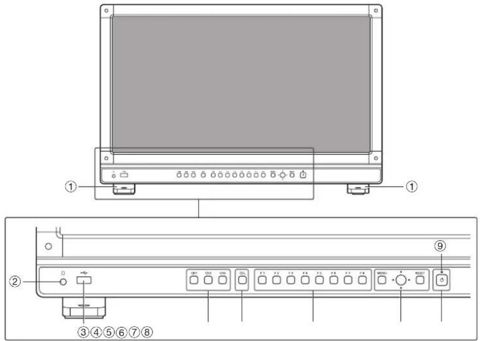
| 1 | Stand There are two mounting positions. | 12 | |
| 2 | Headphone terminal Connection for headphone set. | 70 | |
| 3 | USB port | Connection for an external sensor for calibration (23), USB memory, HUB, color grading controller (Element-Tk made by Tangent Wave Ltd), or wireless LAN adapter (Wi-Fi adapter, 33). | - |
| 4 | CH1 to 3 buttons | Changes channel. | 30 |
| 5 | CDL button | Switches between normal and CDL mode. - | |
| 6 | F1 to F8 buttons | Execute the defined function. You can assign different functions on F buttons in the normal and CDL modes respectively. | 28 |
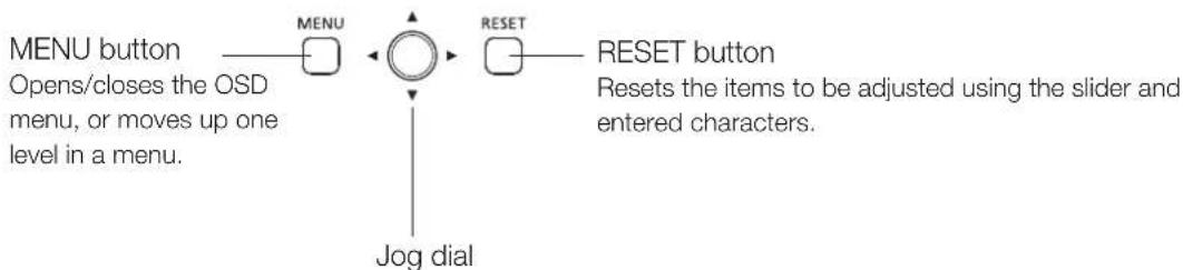
| 7 | MENU button | Opens/closes the OSD menu, or moves up one level in a menu. | 18 |
| Jog dial | Moves the selection frame within the OSD menu, changes the settings (up/down, left/right, rotation) and determines (press) the selection. | 18 | |
| RESET button | Resets the items to be adjusted using the slider and entered characters. | 18 | |
| 8 | (Power) button | Turns power On/Off. | 17 |
| 9 | Power indicator | Displays the status of the main unit. The brightness of the power indicator can be set from "Off" or "1 (dark) to 5 (brightest)" (96). Even when the power indicator is "Off", it will flash during firmware upgrade, or when an error is detected.Off: when AC or DC power supply is not connectedGreen lit: when an AC or DC power supply is connected and the power of the video display is onGreen flash: during calibration or firmware upgradeAmber lit: during standby (an AC or DC power supply is connected and the power of the video display is off)Amber flash: when error is detected | - |
■ Back face of the main unit
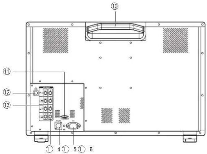
| 10 | Carrying handle Used to install, connect, or carry the unit. | 11 |
| 11 | HDMI input terminal Used to input HDMI signals. | 16 |
| 12 | LAN (10/100 BASE) terminal | - |
| 13 | 3G/HD-SDI output terminal | - |
| 14 | 3G/HD-SDI input terminal | 15 |
| 15 | DC power input terminal | 17 |
| 16 | AC power input terminal | 17 |
CAUTION
- When connecting an external sensor for calibration to the USB port, cable length must not exceed 3 m. Otherwise, communication error may occur and correct calibration may not be possible.
- Do not use the HUB when connecting a wireless LAN adapter (Wi-Fi adapter) to a USB terminal. The video display may not work.
- For safety, do not connect any connector that may have excessive voltage to the terminal of the video display when connecting peripheral devices.
• Pass through SD-SDI signals are not output correctly.

Note
- Both FAT16 and FAT32 USB memory devices are supported.
• Proper operation cannot be guaranteed for all USB memories. - It may take 10 seconds or more for the USB memory to be recognized. If the function to save data on a USB memory is executed during recognition, the message "Detecting USB memory" is displayed.
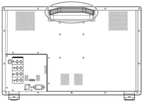
How to Carry the Main Unit
When lifting the video display, be sure to hold the carrying handle on the back.
natural_image
Technical line drawing of a device rear panel with internal components and mounting holes (no text or symbols)
CAUTION
- When carrying the video display, handle it carefully not to touch or damage the screen.
Procedures to attach the protection panel
You can attach the protection panel to protect the screen when carrying the video display or when using it outdoors.
- Unscrew the four screws on the front face.
Use a 1.5 mm hexagonal key.
Do not lose the removed screws. Do not use these screws for other purposes.
- Place the protection panel by aligning its corners with the screw holes.
Take care when attaching the panel in order to avoid damaging it.
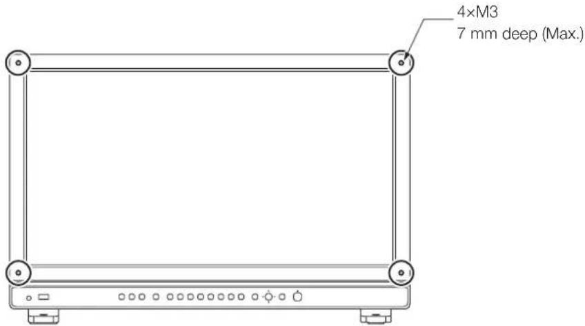

CAUTION
- Avoid touching the screen during this step as it may damage it.
Procedures to attach/detach stands
The stand can be attached in two different positions. This section describes the procedure to attach/detach the stand, to change the stand position. It also describes the procedure for installing the video display on a rack or a wall.

CAUTION
• Use a flat, clear surface when attaching/detaching the stand.
• The display can tip over if the stand has not been attached.
- Avoid touching the screen during this step as it may damage it.
■ Detaching
- Place the display with the screen facing down on a soft cloth or cushioning material that is larger than the display.
- Remove four fixing screws.
Do not lose the removed screws. Do not use these screws for other purposes.
■ Attaching
- Place the display with the screen facing down on a soft cloth or cushioning material that is larger than the display.
- Align the position of the stand and screw hole on the video display.
Alight the convex part of the stand and concave part of the video display.
- Fix the left and right stands using two fixing screws respectively.
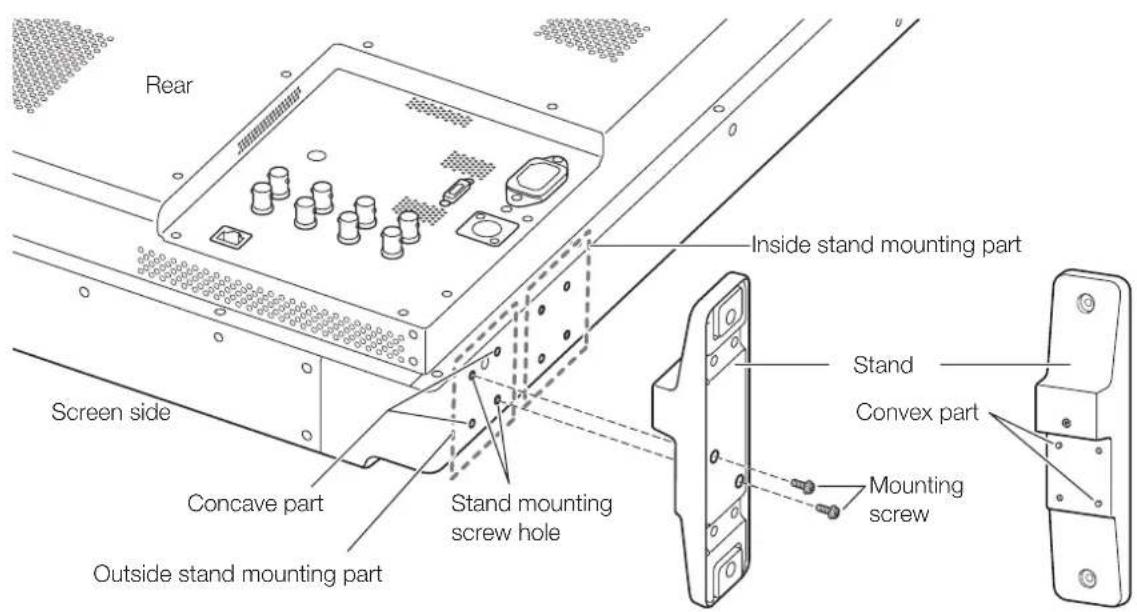

Note
- It is recommended to mount both stands in either the outside or inside positions.
Preventing from Tipping
Fixing the video display using screw holes on the stands can reduce the risk of the main unit tipping over or falling.
1. Use screws that fit the screw holes.
The screw hole size is shown below.
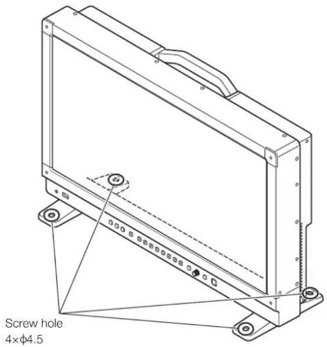
CAUTION
- When securing the main unit to a table or desk, please ensure a table or desk is strong enough to carry the weight of the main unit.
- It is recommended to obtain assistance from another person when performing this step.
- Avoid touching the screen during this step as it may damage it.
Mounting the Main Unit on a Stand or Wall
This main unit can be fitted to a stand* or to a wall mount bracket*. Remove the stands beforehand (12).
Screws compatible with this main unit are M4 x 7 mm (VESA Standard 100 x 100 mm).
* Commercially available.
CAUTION
- For safety, make sure to perform this step with at least two people.
- When mounting the main unit on a wall, make sure the wall has sufficient strength. If necessary, apply reinforcement. Also, make sure to check the load capacity of the stand or wall mount bracket.
- When the video display is placed on a rack or display stand and ventilation around it is blocked by equipment placed above or below or in a surrounding area, the operating temperature may increase, causing a failure or overheating. In order to maintain the operating temperature condition of the video display (0 °C to 40 °C), make a space of at least 1U (4.4 cm) above and below and at least 4 cm space from its back. Make a sufficient space from peripheral equipment, secure vents, or install a ventilation fan.
- When installing the video display on a wall, make sufficient space from the wall so that cables are not squeezed or twisted.
- When mounting a commercially available stand or wall mount bracket, be sure that they do not contact the carrying handle.
- Avoid touching the screen during this step as it may damage it.
• Make sure that the main unit does not fall during installation/removal.
1. Attach a commercially available stand or wall mount bracket using four screw holes on the back or side face of the main unit (104).
The screw hole size is shown below.
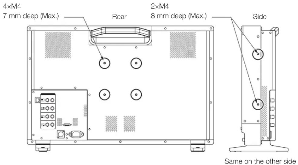
Connecting the Main Unit to Input Devices
The video display has 3G/HD-SDI and HDMI input terminals to connect input devices.
CAUTION
- Check that the power of the video display and input devices is switched off before connecting.
■ SDI input signals
Refer to the 3G/HD-SDI input terminals diagram when connecting to the desired input signal. (A, B, C, D)
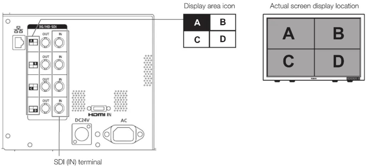
| Input signal Input terminal | ||||
| Quad Link(Square Division) | 3G/HD-SDI Top left | Mapping signal Input A | Single input system | |
| Top right, Mapping signal Input B | ||||
| Bottom left, Mapping signal Input C | ||||
| Bottom right, Mapping signal Input D | ||||
| Quad Link*(2 Sample Interleave) | 3G-SDI Link 1 Input A | |||
| Dual Link* 3G-SDI Link 1 | Input A | Two input systems | ||
| Link 2 Input B | ||||
| Link 1 Input C | ||||
| Link 2 Input D | ||||
| Single Link 3G/HD/SD-SDI | — | Input A/Input B/Input C/Input D | Four input systems | |
* The signals are automatically switched when "Link Order" is set to "Automatic".

Reference
• The connection is tested using 4VS03A-5C BNC cables (multi) manufactured by Canare Electric Co.
- When 3G-SDI RAW signal frequency exceeds 30.00P, it becomes a dual connection.
- Each input terminal is compatible with through output. When signals are input from Input A, connect the cable to the SDI (OUT) terminal of Input A.
■ HDMI input signal
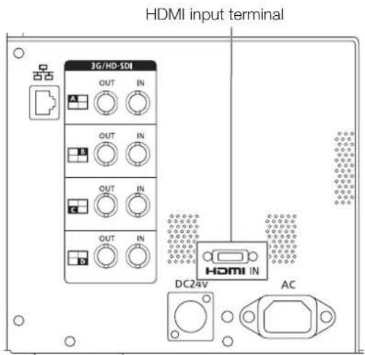

CAUTION
- Use a HDMI cable with the High Speed logo that complies with the HDMI standard. When a non-compliant HDMI standard cable is used, the video display may not work normally, for example a video becomes choppy or nothing is displayed.
This section describes how to turn on the power of the main unit.
Turning on the Power of the Main Unit
- Plug the provided AC power cord HT-21 to the AC power supply input terminal at the rear. The video display goes into standby and the power indicator lights up in amber.
■ When using a DC power supply
DC power supply input terminal specifications are shown below. When connected normally, the video display goes into standby and the power indicator lights up in amber.
Check the specifications of the DC power supply input terminal and use a power supply that is compatible with the video display. Using a power supply with incompatible voltage and polarity may cause fire or electric shock.
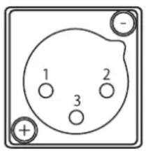
| Pin No. Signal | |
| 1-(GND) | |
| 2+(24 V to 28 V, allowable current 10 A min.) | |
| 3N.C. | |
2. Press the power supply button at the front.
The power indicator lights green.

CAUTION
- When using the provided power plug adapter PU-01, be sure to connect the ground terminal to the ground.
- Use a 2 m or shorter DC cord that can bear an electric current of at least 10 A. When a cable longer than 2 m is used, the video display may not work normally for example a video becomes choppy and nothing is displayed.
- Do not connect cables for audio devices or sound cables to the DC power supply input terminal, as it may cause damage to the display unit.

Note
- Warming-up is necessary to stabilize the brightness of the video display. Wait at least 10 minutes after turning on the power before using.
- When an AC power supply is connected during the use of a DC power supply, the power source is switched to the AC power supply. When this happens, the power is turned off temporarily and then turned on again.
• Refer to the Canon website for detailed information about DC power supplies for which operation has been confirmed.
Operating the Video Display
Using buttons and jog dial on the video display, you can adjust image quality and configure settings for input signals. In addition, you can assign the frequently used functions to the CH and F buttons.
Operating the jog dial
The procedures to operate the jog dial are described below.
flowchart
graph TD
    A["MENU button"] --> B["MENU"]
    B --> C["○"]
    C --> D["RESET"]
    D --> E["RESET button"]
    F["Jog dial"] --> C
    G["Opens/closes the OSD menu, or moves up one level in a menu."] --> A
    H["Reset"] --> D
    I["Reset"] --> E
    J["Reset"] --> E
    K["Reset"] --> E
Up, down, left, right / rotation: Used to move to a different item and change settings.
Press: Confirms settings or moves the selection frame up/down 1 level.
Basic operations to use the OSD menu
This section describes basic operations to use the OSD menu.
- Press the MENU button to open the OSD menu.
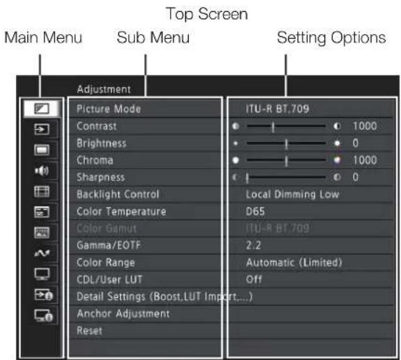
- Select an item using the jog dial and press it to determine the selection.
The selection frame moves to sub menu.
- Select an item using the jog dial and press it to determine the selection.
The selection frame moves to setting options.
- Select the setting using the jog dial.
Settings change according to the operation of the jog dial.
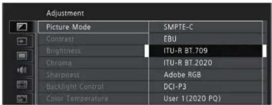
- Press the jog dial to determine the selection.
The selection frame returns to sub menu.
- Exit menu.
When you press the MENU button, the selection frame moves up one menu level. Move the selection frame all the way to the main menu on the top screen and then press the MENU button to exit the menu.

Note
- The following functions can be returned to their factory default settings or their anchor point(1) 21) by pressing the RESET button, after adjusting the image quality.
- "Contrast", "Brightness", "Chroma", "Sharpness", "Power", "Saturation", "Offset", "Slope"
In "User 1-7" mode where you are performing calibration, the setting returns to the value after calibration instead of the factory default.
- To adjust image quality, warming-up is necessary to stabilize the brightness of the video display. Wait at least 10 minutes after turning on the power before using.
- The OSD menu and slider will disappear automatically if no operation is performed for approximately 1 minute. The F button will disappear automatically if no operation is performed for approximately 10 seconds.
• The settings that cannot be set, are grayed out.
Adjusting Image Quality While Viewing the Entire Image
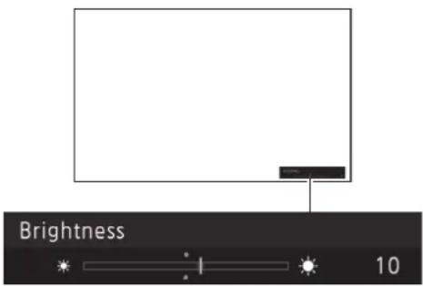
You can adjust the OSD menu to display as a slider at the bottom of the screen. This allows for the image quality to be adjusted whilst it is displayed on the screen.
- Press the jog dial when the selection frame is on setting options.
A slider appears at the bottom of the screen. - Make adjustments using the jog dial with using the slider as guide.
- When adjustments are completed, press the jog dial.
The screen returns to the original OSD menu.
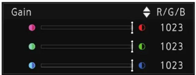
■ Adjusting "Gain R/G/B, Bias R/G/B" under "Color Temperature"
You can adjust RGB all at once or individually when the slider for adjusting "Gain R/G/B" and "Bias R/G/B" are displayed.
- Switch the guide in the upper right area of the slider screen using the jog dial (▲▼).
The indication changes to "RGB", "R", "G", and "B".
- When adjustments are completed, press the jog dial.
The screen returns to the original OSD menu.
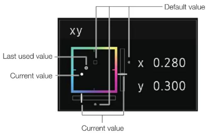
■ Adjusting "x, y" under "Color Temperature"
You can adjust "x, y" in "Color Temperature" on the color map.
-
Adjust "x" with the ◀▶ and "y" with ▲▼
The adjusted value is indicated by the "○" mark on the color map. -
When adjustments are completed, press the jog dial.
The screen returns to the original OSD menu.
Temporarily Saving Parameters (Anchor Point Setting)
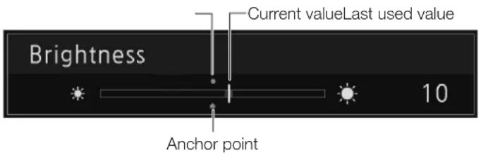
You can temporarily save parameters for "Contrast", "Brightness", "Chroma", "Sharpness", and "HDR Range" and recover the values. See 152 for setting anchor points during CDL adjustment.
- Press the MENU button to open the OSD menu.
- Select "Adjustment" using the jog dial and press the dial to determine the selection.
The selection frame moves to sub menu. - Select "Anchor Adjustment" using the jog dial and press the dial to determine the selection.
When the confirmation screen appears, select "OK". The parameter is saved and sets anchor point. - Adjust the image quality again and press the RESET button on the video display.
Press the RESET button to return to each saved anchor point.

Note
- Executing "Reset" under "Adjustment" or "Reset All Settings" under "System Settings" resets saved anchor points and the settings return to their factory default values.
- When calibration is performed in "User 1-7" under "Picture Mode", the values are saved as anchor points.
Enlarging the display (Zoom function) (68)
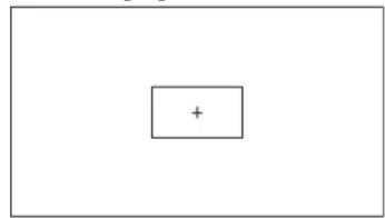
The zoom display position can be adjusted, and the zoom magnification (2x, 4x, 8x) can be selected.
- Press the MENU button to open the OSD menu.
- Select "Display Settings" → "Zoom" using the jog dial.
- Select "Zoom Preset" using the jog dial.
Select a preset zoom display. - Select "Position" using the jog dial.
The zoom adjustment screen is displayed. - To move the display position: Move the jog dial (▲▼◀▶ or rotation).
-
To return to the center: Press the RESET button.
-
When adjustments are completed, press the jog dial.
The screen returns to the original OSD menu.
Zoom 2 [x4]
natural_image
Simple diagram with a rectangle containing a plus sign, no text or symbols present
Note
- When magnifying the image and the OSD menu is not being displayed,
- you can set the magnification ratio by pressing the jog dial.
- You can move the display location by moving the jog dial (▲▼).
- You can set the following functions using the CH button:
CH1: Select zoom type; CH2: Switch between zoom presets (Zoom 1/Zoom 2/Zoom 3); CH3: Zoom off
Changing Image Quality Automatically According to Input Signal
On this video display, you can automatically change the image quality according to video resolution or metadata.
■ Changing "Picture Mode" automatically (62)
- Press the MENU button to open the OSD menu.
- Select "Channel Settings" → "Select Channel" using the jog dial.
Select the channel.
- Select the "Channel Settings" → "Picture Mode" → "Type" using the jog dial.
Select the Type.
Changing by individual video resolution (4K/2K)
Select "4K/2K".
Changing according to video resolution (4K/2K) or metadata (SDI)
Select "Automatic".
- Select the Picture Mode using the jog dial.
■ Changing the image quality setting according to video metadata (HDMI) (56)
- Press the MENU button to open the OSD menu.
- Select "Adjustment" → "Picture Mode" using the jog dial.
Select "User 1" to "User 7".
- Select the "Channel Settings" → "Picture Mode" → "Type" using the jog dial.
Select other than "L/R".
-
Select "Adjustment" > "Detail Settings" > "HDMI Link" > "Automatic Adjustment" using the jog dial.
-
Select "On".
• See "HDMI Link"(□56) for the configurable settings.

Note
- When automatic changing of image quality according to video resolution (4K/2K) or SDI metadata is set, information showing which resolution (4K/2K, etc.) is selected will be displayed at the top right of the menu screen.
Resolution: 4K
Adjust image quality on left/right side of screen (image comparison mode)
You can divide the screen in two and adjust the image quality on the left and right sides of the screen individually.
- Press the MENU button to open the OSD menu.
- Select "Channel Settings" → "Picture Mode" → "Type" using the jog dial.
After selecting "L/R", press the jog dial to determine the selection.
- Select the screen to adjust image quality.
- When the OSD menu is open:
- In the "Adjustment" main menu, press the jog dial's ◀ button.
- In the "Adjustment" main or sub menu, press the CH1 button.
- When the OSD menu is not being displayed: Move the jog dial◀▶.
• Each time the target screen is switched, the set "Picture Mode" is displayed at the top.
- Adjust the image quality on the selected screen.

Note
- When in Image Comparison mode, an icon showing which screen (L/R) is selected for image quality adjustment will be displayed at the right top of the "Adjustment" menu screen.
- The functions that cannot be used when the right screen is selected are as follows.
- Sub Menu items for "Adjustment": "Contrast", "Backlight Control", "Boost Contrast", "HDR/SDR View", "Calibration"
- When two screens are displayed, you can adjust the image quality on each screen individually and compare them.
- When two screens are displaying the same image ("Single Input Dual View" 163)
- When two screens are displaying different images ("Multi View (Dual)" 1.60)
- The HDR (High Dynamic Range) and SDR (Standard Dynamic Range) displays can be tested side by side. ("HDR/SDR View" 54)
Target

Calibration without a PC (55)
When "User 1-7" under "Picture Mode" is selected, you can perform calibration using an external sensor, without using the computer.
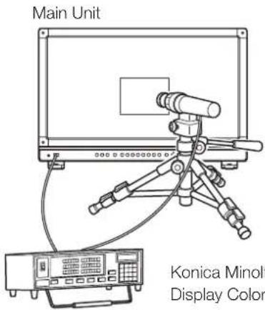
The supported external sensors are Konika Minolta Display Color Analyzers CA-310 and CA-210. Be sure to also read the instruction manual of the CA-310 and CA-210.
The video display can perform measurement or calibration of the display using the DP-V Color Adjustment software. Refer to the Canon website for the DP-V Color Adjustment.
- Connect the display color analyzer to the USB port of the main unit.
- Open the OSD menu and select "Adjustment" → "Detail Settings" → "Calibration". Set each target value.
3. Press the jog dial and select "Start".
Please follow the information indicated on the screen.
4. Initialize the sensor.
Set the mode dial of the Universal Measuring Probe to "0-CAL".
Press the jog dial of the video display, select "OK", and execute initialization.
5. Place the universal measuring probe pointing at the center of the video display.
Set the mode dial of the universal measuring probe to "MEAS" and place the probe as shown below according to the displayed content. Press the jog dial of the video display, select "OK", and execute calibration.
Konica Minolta Universal Measuring Probe
CA-310 support: CA-PU32, CA-PU35
CA-210 support: CA-PU12, CA-PU15
Konica Minolta
Display Color Analyzer CA-310, CA-210
6. Finish calibration.
When the message "Calibration is completed." is displayed, press the jog dial and select "OK".
- If the message "Calibration error." is displayed.
Calibration has been terminated due to an error. The main unit returns to the state before calibration. (22)
• To cancel calibration
Press the jog dial during calibration and select "Cancel". The main unit returns to the state before calibration.

Note
- Due to the characteristic of LCD panel and individual difference of CA-310 and CA-210, the calibration results may differ.
- Perform matrix calibration of the display color analyzer prior to calibration. If calibration is performed without performing matrix calibration, an error may occur. Refer to the CA-310 and CA-210 instruction manual for the detail operation.
- Warming-up is necessary to stabilize the brightness of the video display. Wait at least 10 minutes after turning on the power before calibration.
- Perform calibration in a dark room so that no external light enters the sensor. If external light enters the sensor, low brightness characteristics cannot be calibrated correctly.
Export/Import
You can export/import LUT and CDL parameters as well as main menu settings. Insert a USB memory stick into the USB port of the main unit.
■ LUT Import (53)
- Press the MENU button to open the OSD menu.
- Select "Adjustment" > "Detail Settings" > "LUT Import" using the jog dial.
- Select the file using the jog dial.
In the "Filename" field, search and display a file with extension ".clut" in the root folder.
-
Select the LUT type using the jog dial.
-
Select the LUT type by using "User LUT", "Gamma LUT" or "Gamut LUT".
-
Refer to the "Concept Drawing of Display Image Processing and LUT". Or, also refer to the "User LUT Creation Guide" on the Canon website.
-
Select "Select LUT" using the jog dial.
Selects User LUT/Gamma LUT/Gamut LUT 1-8.
- Select the standard color gamut using the jog dial.
Select the color gamut used when creating the LUT (when "Gamut LUT" under "LUT Type" is selected).
- Select "Execute" using the jog dial.
When the confirmation screen appears, select "OK". Import starts.

Note
- The LUT file is proprietary to Canon Video Display. Refer to the Canon website for the file format and how to create.
- Up to 1000 LUT import files are recognized.
- You can delete the imported LUT. You can specify the name of LUT(153).
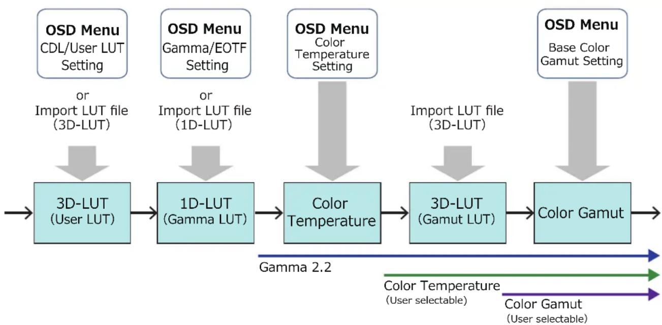
flowchart
graph LR
    A["OSD Menu\nCDL/User LUT Setting"] --> B["3D-LUT\n(User LUT)"]
    C["OSD Menu\nGamma/EOTF Setting"] --> D["1D-LUT\n(Gamma LUT)"]
    E["OSD Menu\nColor Temperature Setting"] --> F["Color Temperature"]
    G["OSD Menu\nBase Color Gamut Setting"] --> H["Color Gamut"]
    B --> I["or Import LUT file (3D-LUT)"]
    D --> J["or Import LUT file (1D-LUT)"]
    F --> K["Color Temperature"]
    H --> L["Color Gamut"]
    style A fill:#cce5ff,stroke:#333
    style C fill:#cce5ff,stroke:#333
    style E fill:#cce5ff,stroke:#333
    style G fill:#cce5ff,stroke:#333
    style B fill:#cce5ff,stroke:#333
    style D fill:#cce5ff,stroke:#333
    style F fill:#cce5ff,stroke:#333
    style H fill:#cce5ff,stroke:#333
    style I fill:#cce5ff,stroke:#333
    style J fill:#cce5ff,stroke:#333
    style K fill:#cce5ff,stroke:#333
    style L fill:#cce5ff,stroke:#333
    subgraph Gamma_2.2
        direction TB
        I -->|Color Temperature\n(User selectable)| J
        J -->|Color Gamut\n(User selectable)| H
    end
Concept Drawing of Display Image Processing and LUT
■ Export/Import Main Menu Settings (198)
- Press the MENU button to open the OSD menu.
- Select "System Settings" → "Export/Import".
- Select "Export" or "Import" using the jog dial.
Exporting
- Select "Target" from "USB", "User 1-3" or "LAN". Export "USB" to the USB memory and "User 1-3" to the built-in memory of the main unit. When you select "LAN", the file is exported to a display connected via LAN.
- If you selected "USB" or "User 1" to "User 3", select "Filename".
- Factory default is "dinfo_dpv2410.dat". You can change the name of the file to be exported to the USB memory within 16 one-byte characters including alphabetical characters, numbers, and symbols.
If you selected "LAN", select "Display".
- Select the display to which to export the settings from the displays connected via LAN.
- Select "Execute".
When the confirmation screen appears, select "OK". Export starts.
Importing
- Select "Target" from "USB" or "User 1-3".
Specify the destination to save the file to be imported. - Select "Filename".
- In "Settings", select "All" or Main Menu name.
- Select "Execute".
When the confirmation screen appears, select "OK". Import starts.

Note
- After export to "User 1-3", you can select the configurations at startup from "User 1-3" in "Power on Setting" in "System Settings" (98).
• To export this device's settings to other Canon displays: - If a display model has functions with different menu settings or setting ranges, some settings will not be correctly exported (settings will not be changed, will revert to factory defaults, etc.)
- When the export is completed, a message will appear on the target display.
■ Exporting/Importing CDL Parameters (52)
- Press the MENU button to open the OSD menu.
- Select "Adjustment" → "CDL/User LUT" using the jog dial.
Select "CDL 1-8".
- Select "Detail Settings" > "CDL Export" or "CDL Import".
Exporting
- Select "CDL Preset".
- Select a file format ".ccc" or ".cdl".
- Select "Execute".
When the confirmation screen appears, select "OK". Export starts.
Importing
- Select "Filename".
- Select "CDL Preset".
- Select "Execute".
When the confirmation screen appears, select "OK". Import starts.

Note
- The exported file is automatically saved under the name "YYYYMMDDhhmmss_Preset name.ccc(cdl)".
- Up to 1000 CDL import files are recognized.
Set Date/Time (95)
This section describes how to set the Date/Time. The Date/Time of this video display will be reset if the power cord is not connected for about 20 days.
- Press the MENU button to open the OSD menu.
- Select "System Settings" → "Date/Time".
A screen to input the Date/Time appears.
- Set the Date/Time using the jog dial.
The selection frame moves and numbers change as you operate the jog dial. Repeat until you complete setting the year, month, date, hour, and minute.
- Press the jog dial when you are finished.
The selection frame moves to "OK".
- Check the content and press the jog dial to confirm the settings.

Reference
- When selecting "Cancel" or pressing MENU button before selecting "OK", the settings will be reset and the previous screen will be displayed.
Inputting Characters
This section describes how to input the characters.
- Press the MENU button to open the OSD menu.
- The character input screen appears automatically when character input is required.
Move the selection frame to the location to enter characters using the jog dial (◀◀).
- Select characters using the jog dial (▲▼rotation).
The following characters can be selected: Press ▲▼ buttons to display them one by one.
Alphanumeric characters: A to Z, a to z, 0 to 9
Symbols: , . : ; ` - + / = % & ! ? # _ | \$ ^ \~ @ { } [ ] < > () space
Characters that cannot be entered are automatically skipped.
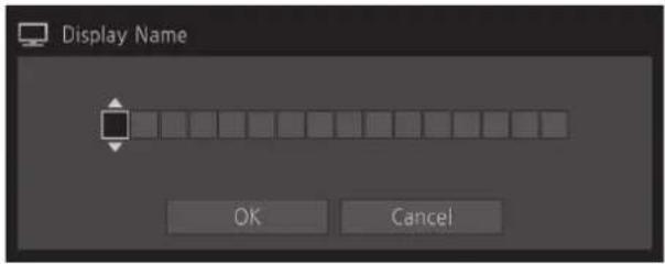
-
Repeat steps 2 and 3 until the desired text has been inputted.
-
Press the jog dial when you are finished.
The selection frame moves to "OK".
- Check the content and press the jog dial to confirm the settings.
i Reference
- When selecting "Cancel" or pressing MENU button before selecting "OK", the settings will be reset and the previous screen will be displayed.
• To erase characters in the selection frame or reset it, press the RESET button on the video display.
Using the Function (F) Buttons
You can assign functions to the F buttons on the video display to execute them instantly.
- Press the MENU button to open the OSD menu.
- Select "System Settings" → "Function/Channel Button" → "Display Function" or "Display Function (CDL)" and press the jog dial to determine the selection.
A new window opens and displays button names F1 to F8. - Select the name of the button using the jog dial and press the jog dial to determine the selection. The selection frame moves to next OSD menu level.
- Select the function to assign using the jog dial. See "Display Function" or "Display Function (CDL)" (95, 99) for the available functions.
- Press the jog dial to determine the selection. The setting is confirmed.

Reference
- Holding the F button down will display the function selection screen, and you can set the function you wish to register.
- Turning "System Settings"→ "OSD Settings" → "Function Button Guide" to "On" will mean that when OSD is not displayed, pressing/moving (▲▼◀▶, or rotate) the jog dial will allow you to see the list of functions registered to the F button. Selecting a function from the list and pressing/moving (▶) the jog dial will display the detailed settings screen, or execute that function.
Using the Channel (CH) Button
You can assign channels (various settings related to input signal) to the CH buttons on the video display and switch channels instantly.
- Press the MENU button to open the OSD menu.
- Select "System Settings" → "Function/Channel Button" → "Display Channel" and press the jog dial to determine the selection.
A new window opens and displays button names CH1 to CH3.
- Select the name of the button using the jog dial and press the jog dial to determine the selection.
The selection frame moves to next OSD menu level.
- Select the channel to assign using the jog dial.
See "Channel Settings" (60) for the configurable settings.
- Press the jog dial to determine the selection.
The setting is confirmed.
The following content is assigned to channel buttons on the video display by factory default.
| CH CH1 CH2 CH3 | ||||
| Input Configuration 3G/HD-SDI | HDMI 3G-SDI RAW | |||
| Select Input Signal Automatic | Automatic Automatic | |||
| Image Division Automatic Automatic | Automatic | |||
| Link Order Automatic Automatic | Automatic | |||
| Format Automatic Automatic | Automatic | |||
| Audio Input Automatic Automatic | Automatic | |||
| Marker/TC/Cameralinfo Input Input A Input A Input A | ||||
| Internal Sync | Off | Off | Off | |
| Channel Name | (Blank) | (Blank) | (Blank) | |
| Picture Mode → Type | Normal | Normal | Normal | |
| Picture ModePicture Mode LResolution 4K | ITU-R BT.709 | ITU-R BT.709 | CINEMA EOS SYSTEM | |
| Picture Mode RResolution 2K | ITU-R BT.709 | |||
| Payload | UHD/PQ | User 1 (2020 PQ) | ||
| UHD/HLG | User 2 (2020 HLG) | |||
| UHD | ITU-R BT.2020 | |||
| 709/PQ | - | |||
| 709/HLG | - | |||
| 709 | ITU-R BT.709 | |||
| VANC | - | |||
| Unknown | - | |||
| Camera CINEMA EOS SYSTEM | CINEMA EOS SYSTEM | |||
| ARRI User 6 | ||||
| VARICAM User 7 | ||||
| Single Input Dual View OffOffOff | ||||
| Separator OffOffOff | ||||

Note
- Holding the CH button down displays the channel list, allowing the user to select the desired channel.
Checking Signal Information and Status of the Main Unit
The video display is equipped with a banner function which displays signal information or the status of the main unit.
1. Press the jog dial when the OSD menu is closed.
The channel name, signal information, and status of the main unit will be displayed in the banner. It will automatically disappear after 6 seconds.

Note
- You can select how the banner is displayed ("Banner" 96).
- You can monitor the input signal status. ("Signal Monitoring" 84)
- For more detailed signal information, please refer to the section on "Signal Information" (101).
- The "Detecting sync." banner will continue to appear until the input signal is synchronized.
Operating the video display using an external device [LAN terminal]
The video display supports Television Systems Ltd.'s "TSL UMD Protocol Ver. 5.0". You can operate the video display using an external device connected to the LAN terminal and display characters and tally lights on the screen. There are two tally lights, on the left and right. Up to 16 characters can be displayed.
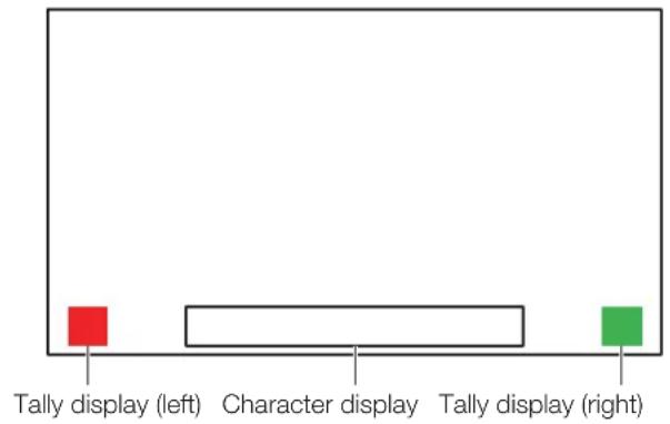
- Connect an external control device to the LAN terminal.
- Set "SCREEN" and "INDEX" to "0x0000" in the TSL Protocol settings.
- Press the MENU button to open the OSD menu.
- Select "Network/IMD Settings" > "In Monitor Display" and press the jog dial to determine the selection.
- Select "Control" > "TSL Ver. 5.00" using the jog dial.
- This will allow operation from an external control device, and display characters and tally lights.
- Select "Position" > "Top" or "Bottom" using the jog dial.
• This sets the position where characters and tally lights will be displayed.
![CANON DP-V2410 - Operating the video display using an external device [LAN terminal] - 2](/content/2026/05/1005757/images/30ee95471cf7c8de404e0b27048c8d560df911717d9895de83e66055b2fe0aa5.jpg)
Note
- When "Multi View (Dual)" or "Multi View (Quad)" is displayed, set the "INDEX" setting to from "0x0001" to "0x0004".
• The port number for the controlling is fixed at "45000". - With "In Monitor Display" you can also display user-selected characters on the screen. (194)
Operating the video display using an external device [USB terminal: Wi-Fi connection]
A Wi-Fi adapter can be connected to the USB terminal of the video display so that the video display can be connected to a portable terminal in the Wi-Fi network environment in use. The following two methods can be used to connect: Infrastructure: This method connects to Wi-Fi via an access point.
Access Point: This device acts as an access point, and this method connects the device directly to the Wi-Fi device.
• Network settings such as IP address and subnet mask are acquired automatically.
• Supported encryption schemes
Infrastructure: WEP64 (ASCII), WEP128 (ASCII), WPA-TKIP, WPA-AES (CCMP), WPA2-TKIP, WPA2-AES (CCMP)
Access Point: WPA2-AES (CCMP)
CAUTION
- Note that we cannot accept any liability for damages that arise as a result of incorrect settings made on the network to use network functions and for damage that arise as a result of use of this function.
- Avoid connecting to Wi-Fi or network environments that are not protected by appropriate security measures. Remember to change the default password when setting the access point. Doing so may cause the customers' personal information or other important information to leak to a third party. When not using Wi-Fi, set "Wi-Fi" → "Control" to "Off".
- The specifications and restrictions of Wi-Fi connection methods differ depending on the Wi-Fi network in use.
- There is no guarantee that the Wi-Fi adapter functions in use will work on the video display. For information about Wi-Fi adapter related defects, contact the device manufacturer. Also, in various countries and regions, approval is needed to use the Wi-Fi adapter, and use of non-approved Wi-Fi adapters is not permitted. If you are unclear of whether or not use is approved, check with the device manufacturer.
Note
• Refer to the Canon website for a list of supported devices (Wi-Fi adapters).
- For details on how to use the Wi-Fi adapter, precautions for use, how to set access points, and other information, either refer to the device Instruction Manual or contact the manufacturer.
- Up to 24 access points can be displayed and selected on the video display.
- Connect the Wi-Fi adapter to the USB terminal.
- Press the MENU button to open the OSD menu.
- Select "Network/IMD Settings" → "Wi-Fi", and press the jog dial to determine the selection.
When using the "Infrastructure" method
- Select "Control" → "Infrastructure" using the jog dial.
- Set the access point to connect to.
- If a password is needed when connected to an access point, enter the password (93).
- This is set using up to 24 alpha-numerical characters and symbols. The following characters can be entered.
Alphanumeric characters: A to Z, a to z, 0 to 9
Symbols: _ or -
When using the "Access Point" method
-
Select "Control" → "Off" using the jog dial.
-
Select "Access Point" using the jog dial (93).
-
Enter the SSID. This is set using up to 24 alpha-numerical characters and symbols.
- Sets the communication mode.
- Sets the channel.
- Enter the password. This is set using between 8 and 24 alpha-numerical characters and symbols.
- "SSID", "Password": The following characters can be entered.
Alphanumeric characters: A to Z, a to z, 0 to 9
Symbols: _ or -
- Select "Control" > "Access Point" using the jog dial.
Use a web browser to remotely operate the video display
A web browser can be used to remotely operate the video display using a computer terminal connected to the LAN terminal or a portable terminal (☐3) connected via a Wi-Fi adapter to the USB terminal. From the device connected to the network, you can change image quality settings or switch channels.
This function checks operation using the following web browsers.
- Safari (Apple)
• Google Chrome (Google)
* Correct operation cannot be guaranteed on all supported OS or web browser editions.

CAUTION
- Remember to change the initial settings for ID and Password when using this function.

Note
- Access is only possible from a single terminal.
- This function may not work if the video display is accessed using LAN and a Wi-Fi adapter, at the same time.
- Opening multiple pages in multiple tabs on the web browser can cause it to not function properly.
- Executing "Capture" in the "View" screen can cause the video on this video display to pause temporarily.
- Operating the video display itself while it is being accessed from a web browser can cause the network connection to be lost.
- A delay may occur in video display or in the various settings depending on the network environment and communication conditions.
-
The IP address can be checked in the "System Information" screen.
• The operation screen only displays English. -
Connect external control devices via the network.
- Press the MENU button to open the OSD menu.
- Select "Network/IMD Settings" > "Web", and press the jog dial to determine the selection.
- Select "Control" > "On" using the jog dial.
- Select "User ID" and "Password" using the jog dial (93).
- User ID: Enter the user ID. This is set using up to 16 alpha-numerical characters and symbols.
Password: Enter the password. This is set using between 8 and 16 alpha-numerical characters and symbols. The following characters can be entered.
Alphanumeric characters: A to Z, a to z, 0 to 9
Symbols: _ or -
-
Start up a web browser on the device connected to a network.
-
Enter the IP address of this video display in the address bar.
-
The remote operation screen is displayed on the web browser.
-
When the basic authentication screen is displayed, enter the user ID and password.
-
When operation ends, close the web browser.
Operation screen
"View" screen
After pressing the image capture button, the captured image will be displayed. You can also operate the CH buttons and F buttons (function/channel buttons).
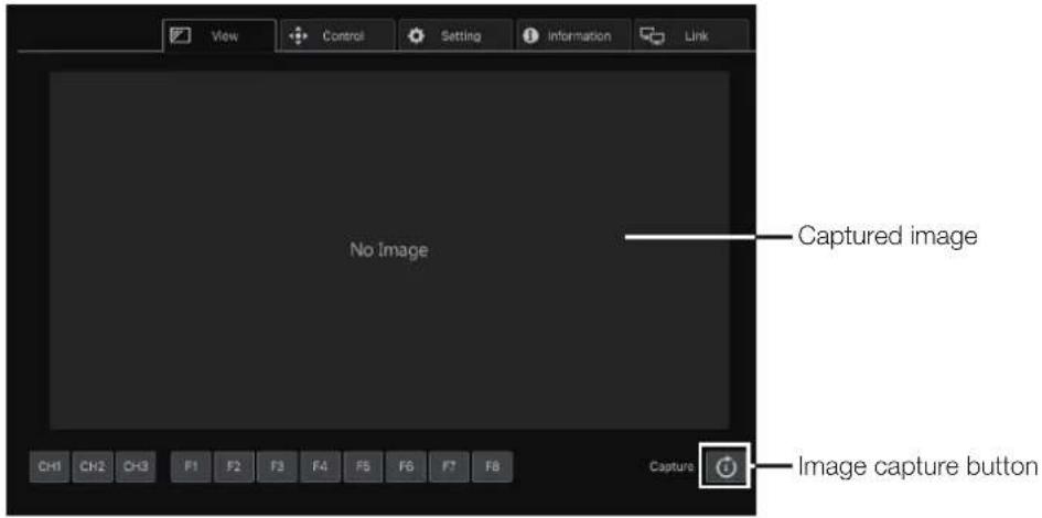
"Control" screen
Allows the Picture Mode, Channel, and various marker displays to be set.
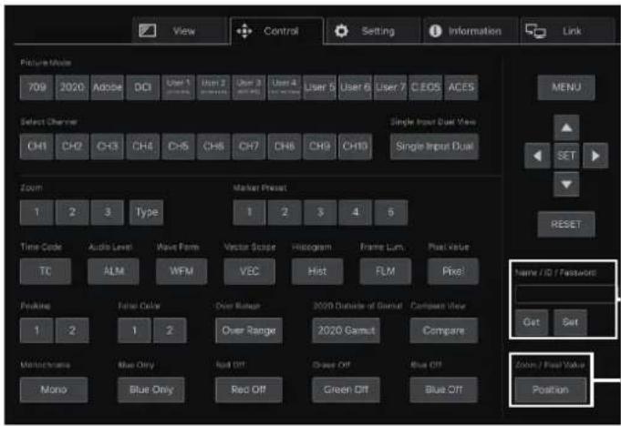
"Name / ID /Password"
Enter the text.
Get: Get the text data to be entered.
Set: Apply the text data to the text input screen.
"Zoom / Pixel Value"
Sets the display position for "Zoom" or the pixel position for "Pixel Value Check".
"Setting" screen
You can import LUT, export "Frame Luminance Monitor", and import or export this video display's settings.
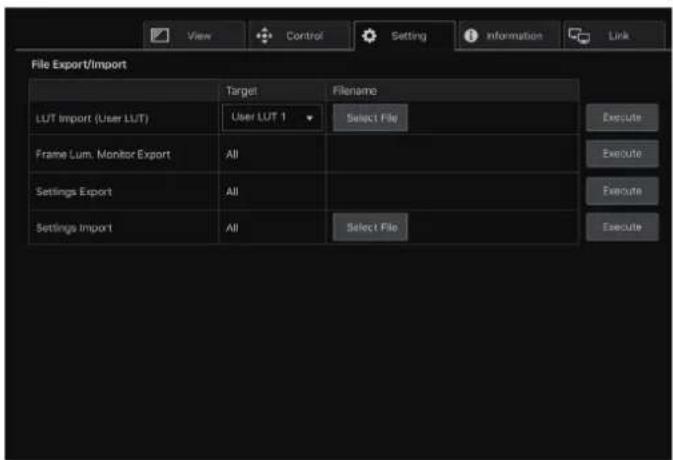
"LUT Import (User LUT)"
Imports a LUT. When the LUT import is completed, the setting of the imported LUT will be applied to the current "Picture Mode"'s "CDL/User LUT".
"Frame Lum. Monitor Export"
Exports "Frame Luminance Monitor". Exporting "Frame Luminance Monitor" will create a "latest.csv" file for the luminance in the final screen and an "all.tar.gz" file (a file compressed using the tar.gz method) that contains all acquired luminance information.
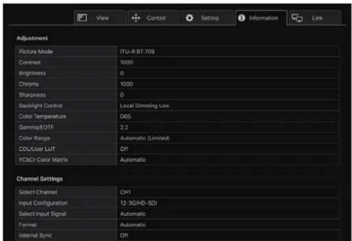
"Information" screen
Displays the settings for "Adjustment" and "Channel Settings", and information for "Signal Information" and "System Information".
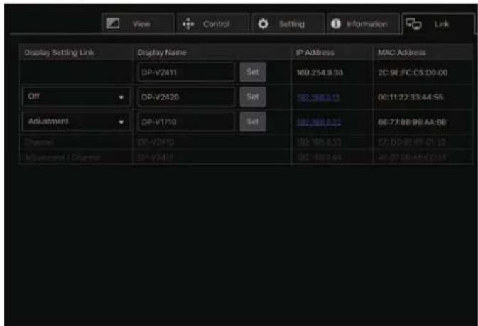
"Link" screen
You can display a list of the display connected via LAN to this video display, set "Display Setting Link", and change the display names.
OSD Menu Index
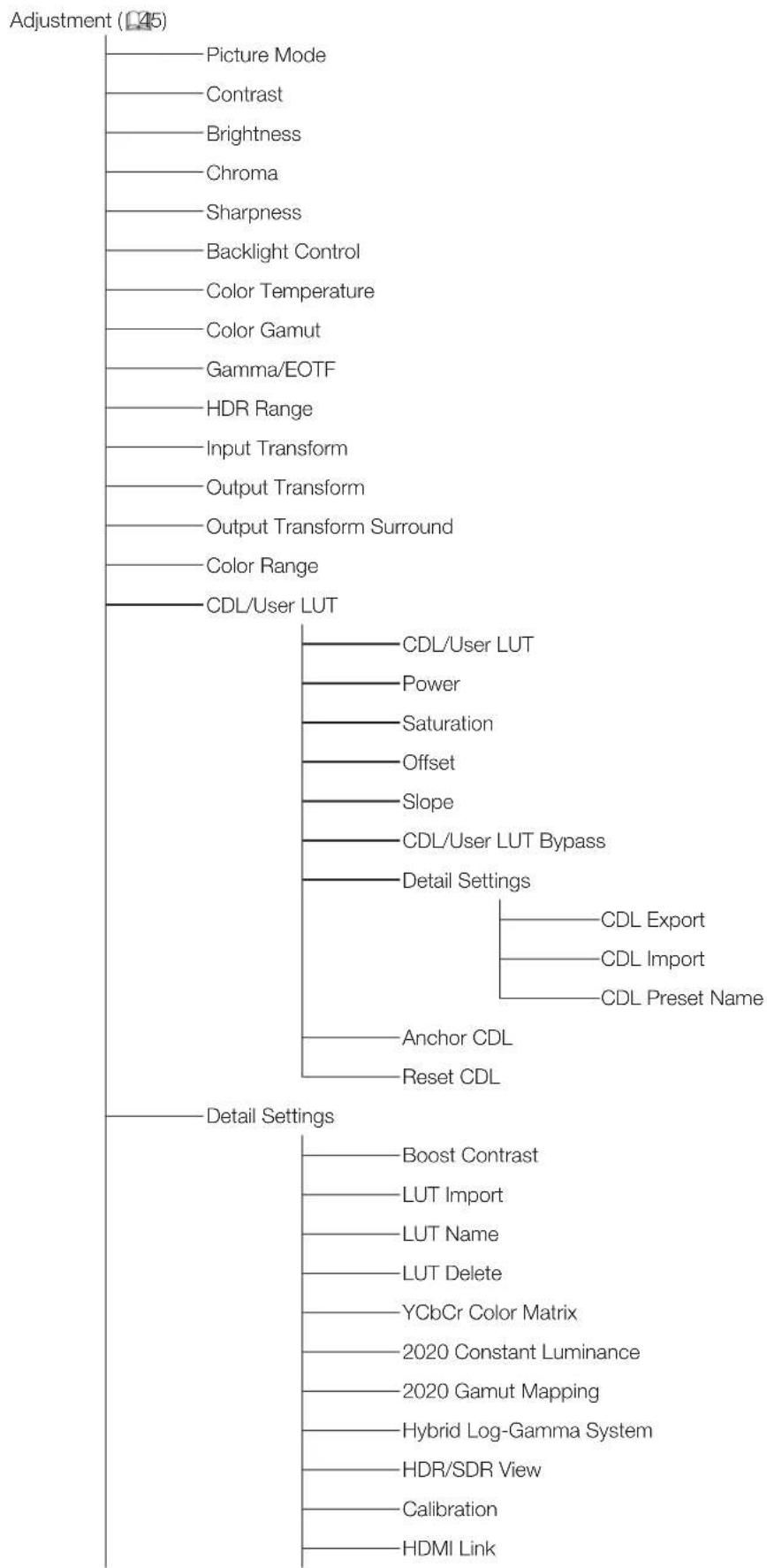
tree
| Category | Item | | :--- | :--- | | Adjustment (L45) | Picture Mode | | Adjustment (L45) | Contrast | | Adjustment (L45) | Brightness | | Adjustment (L45) | Chroma | | Adjustment (L45) | Sharpness | | Adjustment (L45) | Backlight Control | | Adjustment (L45) | Color Temperature | | Adjustment (L45) | Color Gamut | | Adjustment (L45) | Gamma/EOTF | | Adjustment (L45) | HDR Range | | Adjustment (L45) | Input Transform | | Adjustment (L45) | Output Transform | | Adjustment (L45) | Output Transform Surround | | Adjustment (L45) | Color Range | | Adjustment (L45) | CDL/User LUT | | Detail Settings | CDL/User LUT | | Detail Settings | Power | | Detail Settings | Saturation | | Detail Settings | Offset | | Detail Settings | Slope | | Detail Settings | CDL/User LUT Bypass | | Detail Settings | Detail Settings | | Detail Settings | Anchor CDL | | Detail Settings | Reset CDL | | Detail Settings | Boost Contrast | | Detail Settings | LUT Import | | Detail Settings | LUT Name | | Detail Settings | LUT Delete | | Detail Settings | YCbCr Color Matrix | | Detail Settings | 2020 Constant Luminance | | Detail Settings | 2020 Gamut Mapping | | Detail Settings | Hybrid Log-Gamma System | | Detail Settings | HDR/SDR View | | Detail Settings | Calibration | | Detail Settings | HDMI Link |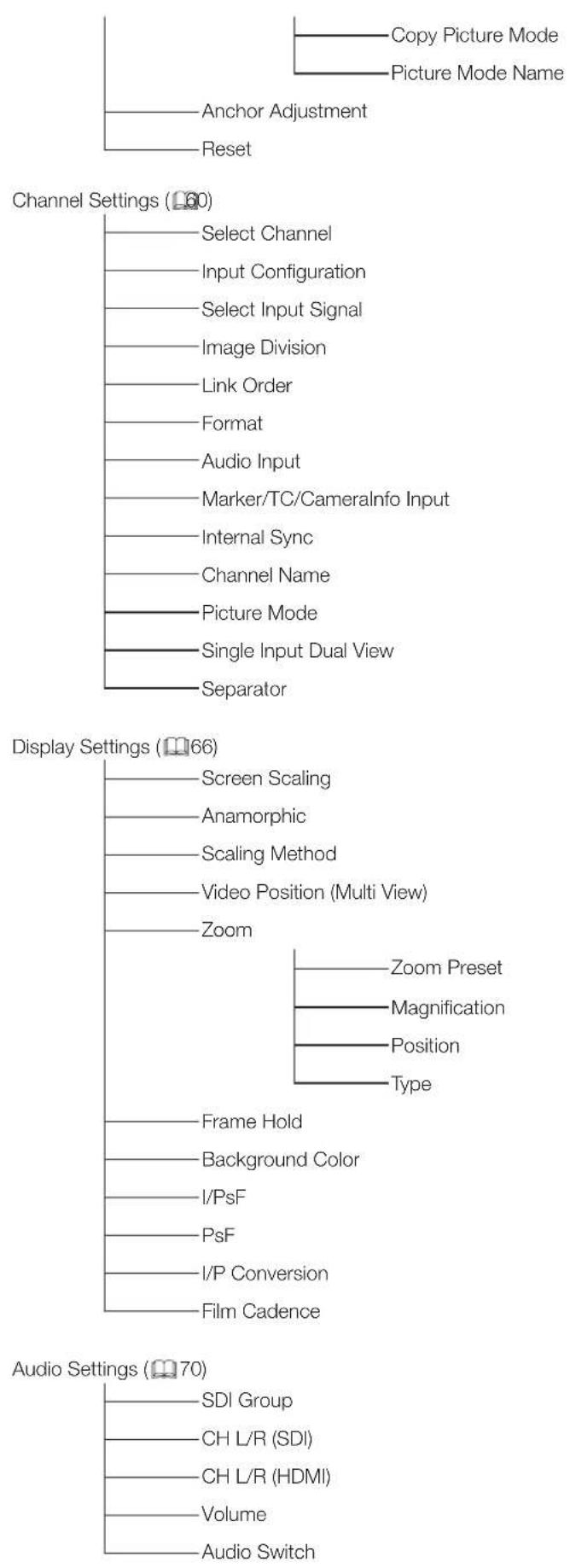
flowchart
graph TD
    A["Copy Picture Mode"] --> B["Picture Mode Name"]
    C["Anchor Adjustment"] --> D["Reset"]
    E["Select Channel"] --> F["Input Configuration"]
    G["Select Input Signal"] --> H["Image Division"]
    I["Link Order"] --> J["Format"]
    K["Audio Input"] --> L["Marker/TC/Cameralinfo Input"]
    M["Internal Sync"] --> N["Channel Name"]
    O["Picture Mode"] --> P["Single Input Dual View"]
    Q["Separator"] --> R["Separator"]
    S["Screen Scaling"] --> T["Anamorphic"]
    U["Scaling Method"] --> V["Video Position (Multi View)"]
    W["Zoom"] --> X["Zoom Preset"]
    Y["Frame Hold"] --> Z["Background Color"]
    AA["I/PsF"] --> AB["PsF"]
    AC["I/P Conversion"] --> AD["Film Cadence"]
    AE["SDI Group"] --> AF["CH L/R (SDI)"]
    AG["CH L/R (HDMI)"] --> AH["Volume"]
    AI["Audio Switch"] --> AJ["Audio Settings (70)"]
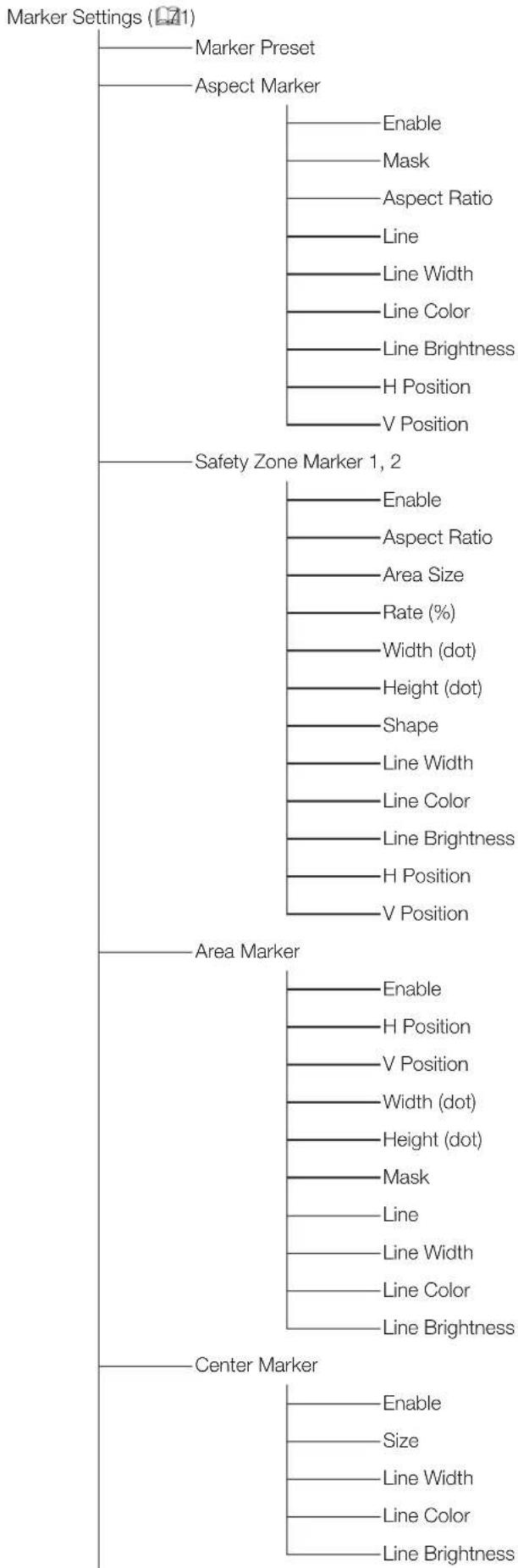
flowchart
graph TD
    A["Marker Settings (L21)"] --> B["Marker Preset"]
    A --> C["Aspect Marker"]
    C --> D["Enable"]
    C --> E["Mask"]
    C --> F["Aspect Ratio"]
    C --> G["Line"]
    C --> H["Line Width"]
    C --> I["Line Color"]
    C --> J["Line Brightness"]
    C --> K["H Position"]
    C --> L["V Position"]

    M["Safety Zone Marker 1, 2"] --> N["Enable"]
    M --> O["Aspect Ratio"]
    M --> P["Area Size"]
    M --> Q["Rate (%)"]
    M --> R["Width (dot)"]
    M --> S["Height (dot)"]
    M --> T["Shape"]
    M --> U["Line Width"]
    M --> V["Line Color"]
    M --> W["Line Brightness"]
    M --> X["H Position"]
    M --> Y["V Position"]

    Z["Area Marker"] --> AA["Enable"]
    Z --> AB["H Position"]
    Z --> AC["V Position"]
    Z --> AD["Width (dot)"]
    Z --> AE["Height (dot)"]
    Z --> AF["Mask"]
    Z --> AG["Line"]
    Z --> AH["Line Width"]
    Z --> AI["Line Color"]
    Z --> AJ["Line Brightness"]

    AK["Center Marker"] --> AL["Enable"]
    AK --> AM["Size"]
    AK --> AN["Line Width"]
    AK --> AO["Line Color"]
    AK --> AP["Line Brightness"]
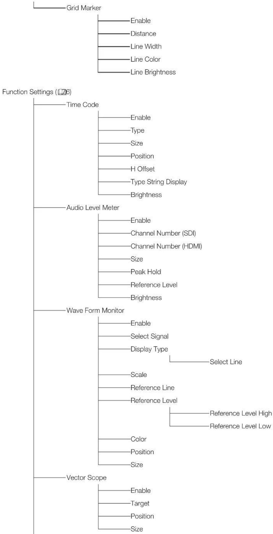
flowchart
graph TD
    A["Grid Marker"] --> B["Enable"]
    A --> C["Distance"]
    A --> D["Line Width"]
    A --> E["Line Color"]
    A --> F["Line Brightness"]
    G["Function Settings (76)"] --> H["Time Code"]
    G --> I["Audio Level Meter"]
    G --> J["Wave Form Monitor"]
    G --> K["Vector Scope"]
    H --> L["Enable"]
    H --> M["Type"]
    H --> N["Size"]
    H --> O["Position"]
    H --> P["H Offset"]
    H --> Q["Type String Display"]
    H --> R["Brightness"]
    I --> S["Enable"]
    I --> T["Channel Number (SDI)"]
    I --> U["Channel Number (HDMI)"]
    I --> V["Size"]
    I --> W["Peak Hold"]
    I --> X["Reference Level"]
    I --> Y["Brightness"]
    J --> Z["Enable"]
    J --> AA["Select Signal"]
    J --> AB["Display Type"]
    J --> AC["Scale"]
    J --> AD["Reference Line"]
    J --> AE["Reference Level"]
    J --> AF["Color"]
    J --> AG["Position"]
    J --> AH["Size"]
    K --> AI["Enable"]
    K --> AJ["Target"]
    K --> AK["Position"]
    K --> AL["Size"]
    style A fill:#f9f,stroke:#333
    style G fill:#ccf,stroke:#333
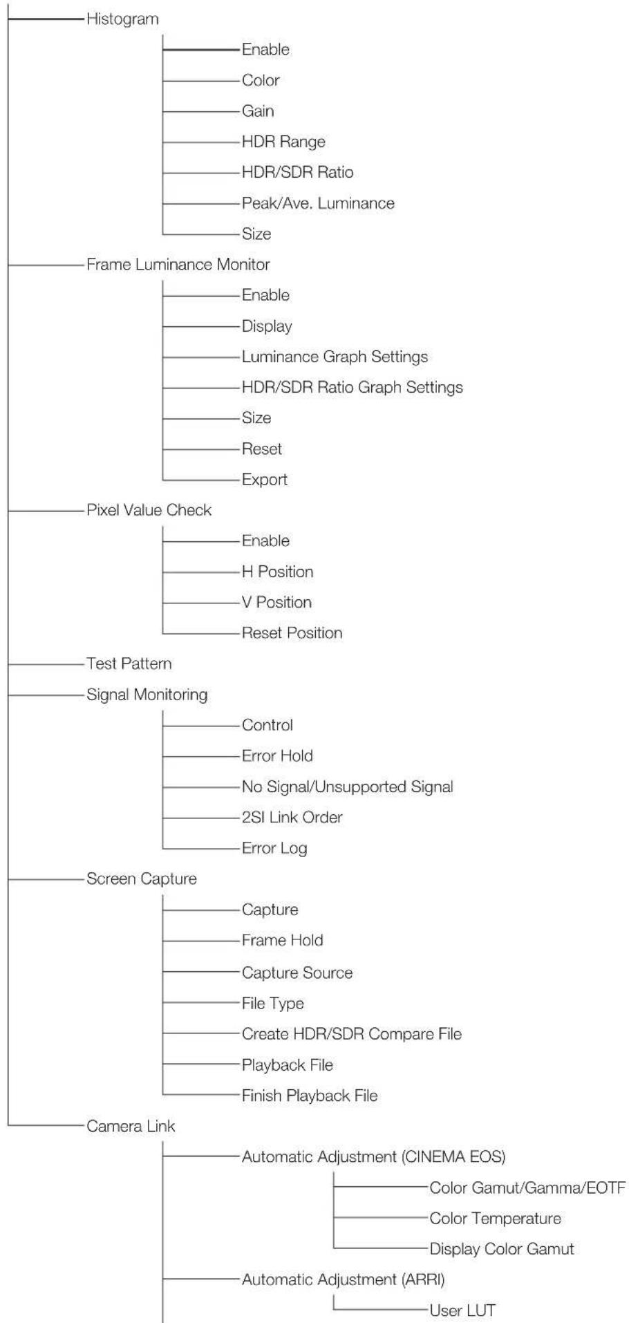
flowchart
graph TD
    A["Histogram"] --> B["Enable"]
    B --> C["Color"]
    C --> D["Gain"]
    D --> E["HOR Range"]
    E --> F["HOR/SDR Ratio"]
    F --> G["Peak/Ave. Luminance"]
    G --> H["Size"]

    A --> I["Frame Luminance Monitor"]
    I --> J["Enable"]
    J --> K["Display"]
    K --> L["Luminance Graph Settings"]
    L --> M["HOR/SDR Ratio Graph Settings"]
    M --> N["Size"]
    N --> O["Reset"]
    O --> P["Export"]

    A --> Q["Pixel Value Check"]
    Q --> R["Enable"]
    R --> S["H Position"]
    S --> T["V Position"]
    T --> U["Reset Position"]

    A --> V["Test Pattern"]
    V --> W["Signal Monitoring"]
    W --> X["Control"]
    X --> Y["Error Hold"]
    Y --> Z["No Signal/Unsupported Signal"]
    Z --> AA["2SI Link Order"]
    AA --> AB["Error Log"]

    A --> AC["Screen Capture"]
    AC --> AD["Capture"]
    AD --> AE["Frame Hold"]
    AE --> AF["Capture Source"]
    AF --> AG["File Type"]
    AG --> AH["Create HDR/SDR Compare File"]
    AH --> AI["Playback File"]
    AI --> AJ["Finish Playback File"]

    A --> AK["Camera Link"]
    AK --> AL["Automatic Adjustment (CINEMA EOS)"]
    AL --> AM["Color Gamut/Gamma/EOTF"]
    AL --> AN["Color Temperature"]
    AL --> AO["Display Color Gamut"]
    AK --> AP["Automatic Adjustment (ARRI)"]
    AP --> AQ["User LUT"]
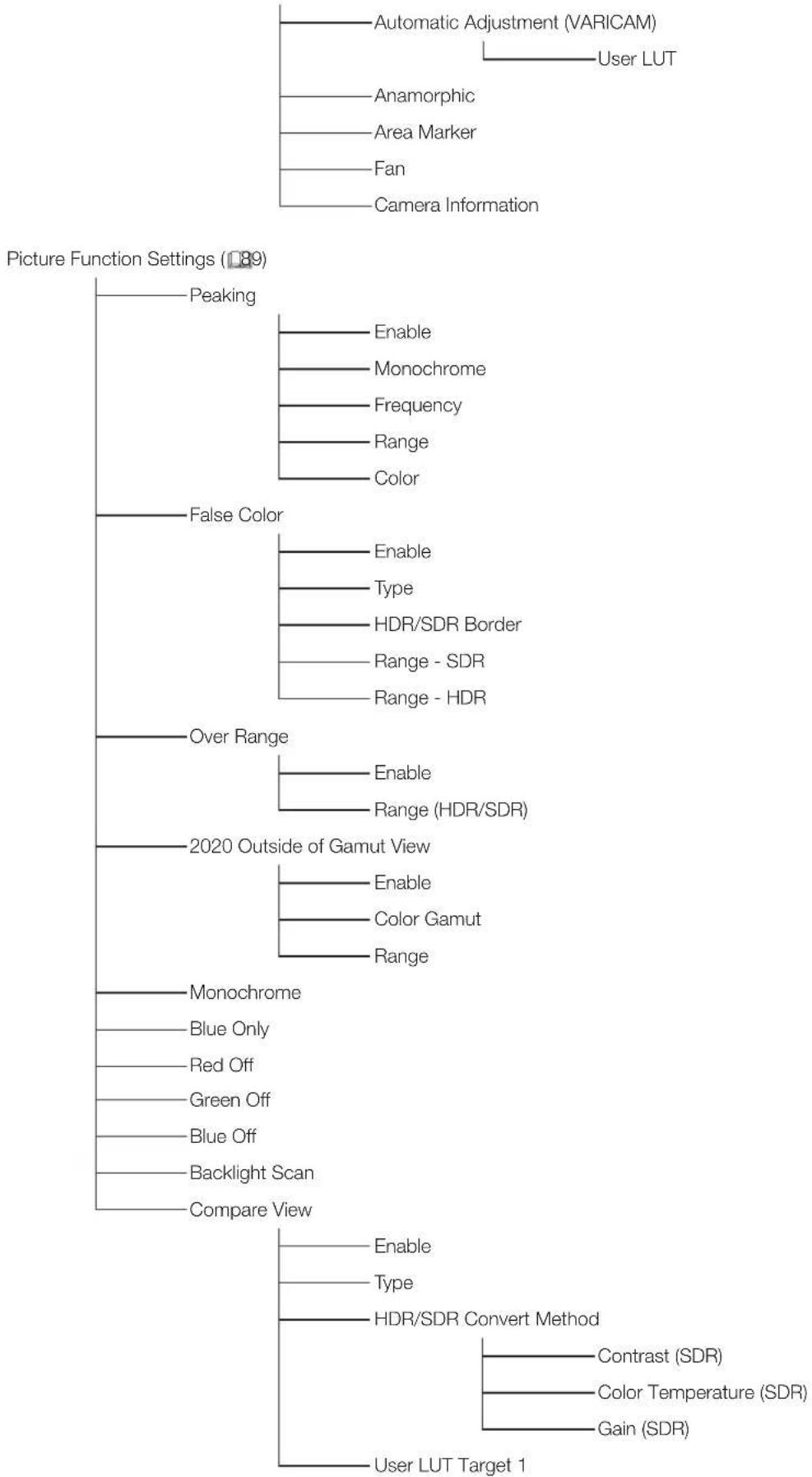
flowchart
graph TD
    A["Automatic Adjustment (VARICAM)"] --> B["User LUT"]
    C["Anamorphic"] --> D["Area Marker"]
    E["Fan"] --> F["Camera Information"]
    G["False Color"] --> H["Enable"]
    G --> I["Type"]
    G --> J["HDR/SDR Border"]
    G --> K["Range - SDR"]
    G --> L["Range - HDR"]
    M["Over Range"] --> N["Enable"]
    M --> O["Range (HDR/SDR)"]
    P["2020 Outside of Gamut View"] --> Q["Enable"]
    P --> R["Color Gamut"]
    P --> S["Range"]
    T["Monochrome"] --> U["Blue Only"]
    T --> V["Red Off"]
    T --> W["Green Off"]
    T --> X["Blue Off"]
    T --> Y["Backlight Scan"]
    T --> Z["Compare View"]
    AA["Enable"] --> AB["Type"]
    AB --> AC["HDR/SDR Convert Method"]
    AD["Contrast (SDR)"] --> AE["Color Temperature (SDR)"]
    AE --> AF["Gain (SDR)"]
    AG["User LUT Target 1"] --> AH["Output"]
Network/IMD Settings (193)
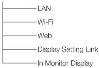
flowchart
graph TD
    A["LAN"] --> B["Wi-Fi"]
    B --> C["Web"]
    C --> D["Display Setting Link"]
    D --> E["In Monitor Display"]
System Settings (95)
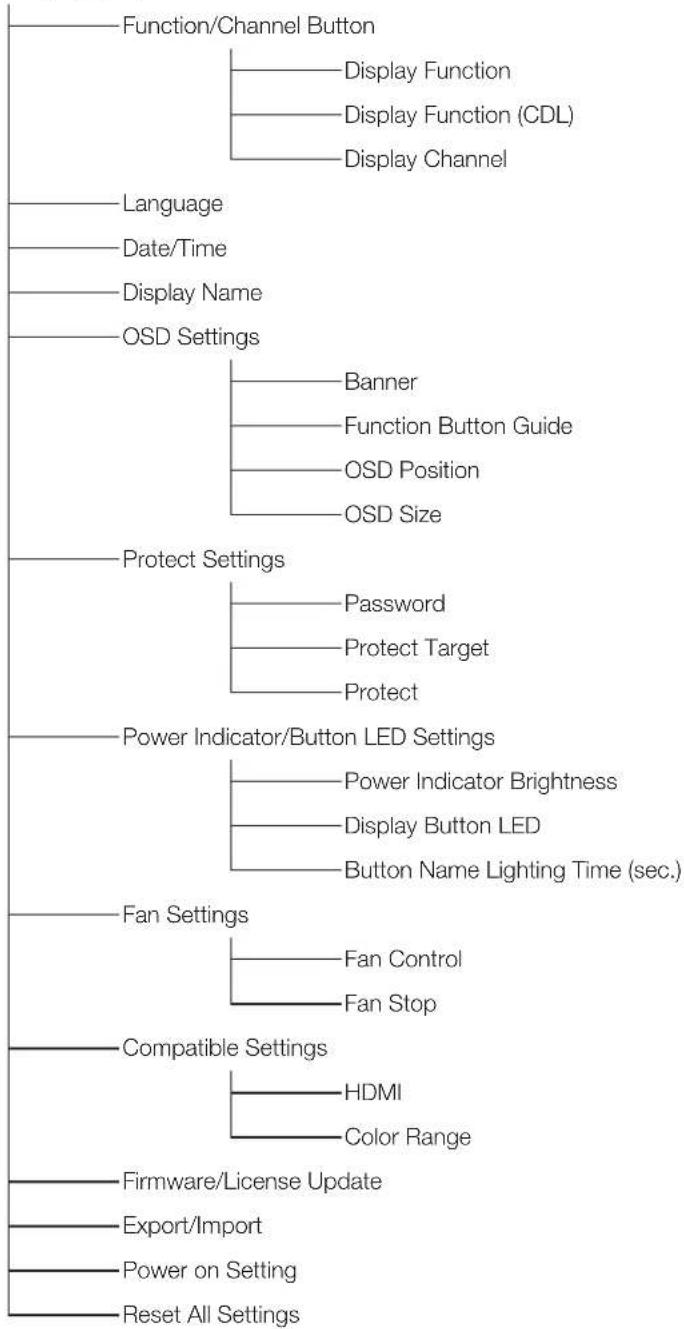
flowchart
graph TD
    A["Function/Channel Button"] --> B["Display Function"]
    A --> C["Display Function (CDL)"]
    A --> D["Display Channel"]
    E["Language"] --> F["Balance"]
    G["Date/Time"] --> H["Balance"]
    I["Display Name"] --> J["Balance"]
    K["OSD Settings"] --> L["Banner"]
    K --> M["Function Button Guide"]
    K --> N["OSD Position"]
    K --> O["OSD Size"]
    P["Protect Settings"] --> Q["Password"]
    P --> R["Protect Target"]
    P --> S["Protect"]
    T["Power Indicator/Button LED Settings"] --> U["Power Indicator Brightness"]
    T --> V["Display Button LED"]
    T --> W["Button Name Lighting Time (sec.)"]
    X["Fan Settings"] --> Y["Fan Control"]
    X --> Z["Fan Stop"]
    AA["Compatible Settings"] --> AB["HDMI"]
    AA --> AC["Color Range"]
    AD["Firmware/License Update"] --> AE["Balance"]
    AF["Export/Import"] --> AG["Balance"]
    AH["Power on Setting"] --> AI["Balance"]
    AJ["Reset All Settings"] --> AK["Balance"]
Signal Information (101)
System Information (101)
Adjustment
This menu is used to adjust the image quality and perform calibration without a PC. The factory defaults differ according to the "Picture Mode" setting. (157)
| Item Setting Options (underline indicates factory default) | |
| Picture Mode | Select a preset mode.SMPTE-C, EBU, ITU-R BT.709, ITU-R BT.2020, Adobe RGB, DCI-P3: Mode set to the brightness, color temperature, gamma/EOTF, and color gamut of the three primary colors chromaticity points of each standard.User 1-7 (User 1 (2020 PQ), User 2 (2020 HLG), User 3 (DCI PQ), User 4 (DCI PQ D65),User 5 ~ User 7): Custom modes. Set each item of "Adjustment". You can change the mode name within 24 one-byte characters including alphabetical characters, numbers, and symbols (56).CINEMA EOS SYSTEM: Canon Log is ideal when viewing image captured with Cinema EOS camera/video camera. Using Camera Link, you can have the image quality setting change automatically ("Automatic Adjustment (CINEMA EOS)" 85).ACESproxy (ver. 1.0.1): A mode to display ACESproxy videos in optimum gamma/EOTF and color gamut.Note"ACESproxy (ver. 1.0.1)" cannot be set when "Channel Settings" > "Picture Mode" > "Type" are "L/R", "4K/2K" or "Automatic". |
| Contrast Adjusts the white level of the image. (Increments of 1)0 to 1500When "Boost Contrast" in "Detail Settings" is set to "On", the settable range is shown below.When "Boost Contrast" is "On", "Contrast [BOOST]" is displayed.1500 to 4000NoteWhen "Channel Settings" > "Picture Mode" → "Type" is "L/R", "Contrast" cannot be adjusted at the "Picture Mode" setting for the right screen. The right screen's setting will be the same as set for the left screen. | |
| Brightness Adjusts the black level of the image. (Increments of 1)-500 to 500 | |
| Chroma Adjusts the color saturation of the image (color depth). (Increments of 1)0 to 2000NoteCan only be adjusted when "CDL/User LUT" is "CDL 1-8" or "Off". | |
| Sharpness Adjusts the sharpness of the image. (Increments of 1)0 to 100 | |
| Backlight Control Switches | the backlight control method.Local Dimming (Auto, High, Low): Local dimming technology controls the amount of light emitted by the backlight for each display area. The backlight of bright area is increased and the dark area is decreased according to the displayed content.When "Auto" is set, the amount of light is automatically controlled according to the contrast value.Increasing the contrast value makes the backlight darker in dark portions of the image as compared to "High"/"Low".Global Dimming: Global dimming is the ability to control the amount of light emitted by the backlight on the entire screen. If the image is dark, the whole display is darkened.Off: No backlight dimming is applied.NoteWhen "Global Dimming" is selected, the contrast may change temporarily in order to maintain gradation depending on the image. If this is undesirable, turn it "Off" and see if it improves.When "Boost Contrast" is set to "On", "Backlight Control" turns to "Off".When "Channel Settings"→ "Picture Mode" → "Type" is "L/R", "Backlight Control" cannot be set at the "Picture Mode" setting for the right screen. The right screen's setting will be the same as set for the left screen. |
| Color Temperature Sets the color temperature. | D93, D65, D61, D60, D56, D50, DCI-P3: Select from preset color temperatures.D65 Custom: This preset is for adjusting the color of the video display and displays having different display characteristics. The gain and bias are adjusted based on D65.Gain R/G/B, Bias R/G/B: Can be adjusted in increments of 1 when a preset color temperature is selected.Gain R/G/B: 0 to 1023Bias R/G/B: -500 to 500Custom (xy): You can adjust CIE x, y in increments of 0.001.x: 0.260 to 0.360y: 0.260 to 0.360Off: Color temperature is not set.Note"Custom (xy)" and "Gain R/G/B" or "Bias R/G/B" cannot be selected at the same time.When "Gain R/G/B" or "Bias R/G/B" value is adjusted, an asterisk "*** is displayed by color temperature preset mode.The displayed color coordinates (x, y) are just a guide and not guaranteed absolute values. |
| Color Gamut | Color gamut can be selected when "User 1-7" or "CINEMA EOS SYSTEM" is selected for "Picture Mode".SMPTE-C, EBU, ITU-R BT.709, ITU-R BT.2020, Adobe RGB, DCI-P3: Color gamut compliant to each standard.Native: Color gamut that can be displayed by this video display.Cinema Gamut to 709, Cinema Gamut to 2020, Cinema Gamut to DCI, DCI-P3+ to 709, DCI-P3+ to DCI: Modes where the color gamut is converted to monitor Cinema Gamut and DCI-P3+ videos recorded by the CINEMA EOS SYSTEM cameras.S-Gamut3 to 709, S-Gamut3 to 2020, S-Gamut3 to DCI, S-Gamut3.Cine to 709, S-Gamut3.Cine to 2020, S-Gamut3.Cine to DCI: Preset modes where the color gamut is converted.Gamut LUT 1 to Gamut LUT 8: Selects an external LUT.Note"Color Gamut" cannot be set in the following cases.- When "CDL/User LUT" → "ARRI (Rec2100-PQ-1K-100)", "ARRI (Rec2100-HLG-1K-200)", "VARICAM (V-Log to V-709)", "2020 PQ to 2020 SDR", "2020 PQ to 709 SDR", "2020 HLG to 709 HLG" or "2020 HLG to 709 SDR" is selected.For checking the video captured with Cinema EOS cameras, please refer to the "Parameter of Cinema EOS cameras and DP-V2410 ( [IMAGE]85)" in "Adjustment". |
| Gamma/EOTF Sets the Gamma/EOTF. | 1.0, 2.2, 2.35, 2.4, 2.6, ITU-R BT.1886, Canon Log, Canon Log 2, Canon Log 3, S-Log2 (HDR), S-Log3 (HDR): Select the preset gamma.SMPTE ST 2084 (PQ), Hybrid Log-Gamma, Hybrid Log-Gamma RGB, Canon Log (HDR), Canon Log 2 (HDR), Canon Log 3 (HDR): Select the gamma/EOTF for HDR display.Gamma LUT 1 to Gamma LUT 8: Selects an external LUT.Off: Gamma is not set.NoteAbout "Hybrid Log-Gamma"- This video display supports the following two methods."Hybrid Log-Gamma": This method processes the system gamma for the Y signal (Compliant with ITU-R BT.2100)."Hybrid Log-Gamma RGB": This method processes the system gamma for the RGB signal.- If using "Hybrid Log-Gamma" then the system gamma value will be displayed in the "Setting Options" on the menu screen.Not settable in the following cases:- When "ACESproxy (ver. 1.0.1)" is selected in "Picture Mode"- When "CDL/User LUT" → "ARRI (Rec2100-PQ-1K-100)", "ARRI (Rec2100-HLG-1K-200)", "VARICAM (V-Log to V-709)", "2020 PQ to 2020 SDR", "2020 PQ to 709 SDR", "2020 HLG to709 SDR" is selected.For checking the captured video with Cinema EOS cameras and ARRI / Panasonic cinema cameras, please refer to "Camera Link" → "Automatic Adjustment" ( [IMAGE]85). |
The relationship between "Color Gamut" and "Gamma/EOTF" that can be selected is shown below. When "Color Gamut" is changed, "Gamma/EOTF" is changed to the underlined value (default value) when the current "Gamma/EOTF" settings are not selectable.
| Picture Mode | Color Gamut Selectable | Gamma/EOTF |
| SMPTE-C Cannot be selected | Off, 1.0,2.2,2.35,2.4,2.6,ITU-R BT.1886,SMPTE ST 2084 (PQ),Canon Log, Canon Log (HDR),Gamma LUT 1 to Gamma LUT 8 | |
| EBU | Off, 1.0,2.2,2.35,2.4,2.6,ITU-R BT.1886,SMPTE ST 2084 (PQ),Canon Log, Canon Log (HDR),Gamma LUT 1 to Gamma LUT 8 | |
| ITU-R BT.709,ITU-R BT.2020 | Off, 1.0,2.2,2.35,2.4,2.6,ITU-R BT.1886,SMPTE ST 2084 (PQ),Hybrid Log-Gamma, Hybrid Log-Gamma RGB,Canon Log, Canon Log (HDR),Canon Log 2,Canon Log 2 (HDR),Canon Log 3,Canon Log 3 (HDR),S-Log2 (HDR),S-Log3 (HDR),Gamma LUT 1 to Gamma LUT 8 | |
| Adobe RGB | Off, 1.0,2.2,2.35,2.4,2.6,ITU-R BT.1886,Gamma LUT 1 to Gamma LUT 8 | |
| DCI-P3 | Off, 1.0,2.2,2.35,2.4,2.6,ITU-R BT.1886,SMPTE ST 2084 (PQ),Canon Log, Canon Log (HDR),Canon Log 2,Canon Log 2 (HDR),Canon Log 3,Canon Log 3 (HDR),S-Log2 (HDR),S-Log3 (HDR),Gamma LUT 1 to Gamma LUT 8 | |
| CINEMA EOS SYSTEM,User 1-7 | SMPTE-C | Off, 1.0,2.2,2.35,2.4,2.6,ITU-R BT.1886,SMPTE ST 2084 (PQ),Canon Log, Canon Log (HDR),Gamma LUT 1 to Gamma LUT 8 |
| EBU | Off, 1.0,2.2,2.35,2.4,2.6,ITU-R BT.1886,SMPTE ST 2084 (PQ),Canon Log, Canon Log (HDR),Gamma LUT 1 to Gamma LUT 8 | |
| ITU-R BT.709,ITU-R BT.2020 | Off, 1.0,2.2,2.35,2.4,2.6,ITU-R BT.1886,SMPTE ST 2084 (PQ),Hybrid Log-Gamma, Hybrid Log-Gamma RGB,Canon Log, Canon Log (HDR),Canon Log 2,Canon Log 2 (HDR),Canon Log 3,Canon Log 3 (HDR),S-Log2 (HDR),S-LOG3 (HDR),Gamma LUT 1 to Gamma LUT 8 | |
| Adobe RGB | Off, 1.0,2.2,2.35,2.4,2.6,ITU-R BT.1886,Gamma LUT 1 to Gamma LUT 8 | |
| DCI-P3 | Off, 1.0,2.2,2.35,2.4,2.6,ITU-R BT.1886,SMPTE ST 2084 (PQ),Canon Log, Canon Log (HDR),Canon Log 2,Canon Log 2 (HDR),Canon Log 3,Canon Log 3 (HDR),S-Log2 (HDR),S-Log3 (HDR),Gamma LUT 1 to GammaLUT 8 | |
| Native | Off, 1.0,2.2,2.35,2.4,2.6,ITU-R BT.1886,SMPTE ST 2084 (PQ),Gamma LUT 1 to Gamma LUT 8 | |
| Cinema Gamut to 709,Cinema Gamut to 2020 | 2.2,Canon Log,Canon Log (HDR),Canon Log 2,Canon Log 2 (HDR),Canon Log 3,Canon Log 3 (HDR) | |
| Cinema Gamut to DCI | Canon Log,Canon Log (HDR),Canon Log 2,Canon Log 2 (HDR),Canon Log 3,Canon Log 3 (HDR) | |
| DCI-P3+ to 709,DCI-P3+ to DCI | Canon Log,Canon Log (HDR) | |
| S-Gamut3 to 709S-Gamut3 to 2020S-Gamut3.Cine to 709S-Gamut3.Cine to 2020 | Off, 1.0,2.2,2.35,2.4,2.6,ITU-R BT.1886,SMPTE ST 2084 (PQ),Hybrid Log-Gamma, Hybrid Log-Gamma RGB, S-Log2 (HDR), S-Log3 (HDR),Gamma LUT 1 to Gamma LUT 8 | |
| S-Gamut3 to DCIS-Gamut3.Cine to DCI | Off, 1.0,2.2,2.35,2.4,2.6,ITU-R BT.1886,SMPTE ST 2084 (PQ),S-Log2 (HDR),S-Log3 (HDR),Gamma LUT 1 to Gamma LUT 8 | |
| Gamut LUT 1 to GamutLUT 8 | Off, 1.0,2.2,2.35,2.4,2.6,ITU-R BT.1886,Gamma LUT 1 to Gamma LUT 8 | |
| Item Setting Options (underline indicates factory default) | |||
| HDR Range | Sets the display method when Gamma/EOTF for HDR display is selected.SMPTE ST 2084 (PQ): Sets the "SMPTE ST 2084 (PQ)" dynamic range to be displayed, from 0.005 to 10,000 cd/m2(nits). (100 to 4000: 100 increments. 4000 to 10000: 1000 increments)100 to 10000 (1000)Hybrid Log-Gamma,Hybrid Log-Gamma RGB: Sets how far to display the "Hybrid Log-Gamma" dynamic range.(in increments of 100)The upper limit value will change to match the settings of "Hybrid Log-Gamma System". (1054)Hybrid Log-Gamma: 100 to 1000Hybrid Log-Gamma RGB: 100 to 1000/2000Canon Log (HDR): Sets the "Canon Log" dynamic range to be displayed, from 0 to 800%. (in 100 increments)100 to 800Canon Log 2 (HDR): Sets the "Canon Log 2" dynamic range to be displayed, from 0 to 1600%. (in 100 increments)100 to 1600Canon Log 3 (HDR): Sets the "Canon Log 3" dynamic range to be displayed, from 0 to 1600%. (in 100 increments)100 to 1600S-Log2 (HDR), S-Log3 (HDR): Sets how far to display the "S-Log" dynamic range.(in 100 increments)S-Log2 (HDR): 100 to 1400 (1000)S-Log3 (HDR): 100 to 3900 (1000)Gamma LUT 1 to Gamma LUT 8: Sets how far to display the 10-bit LUT data dynamic range, from 0 to 1023. (in 1 increments)512 to 1023Setting proceduresThe procedures below use Canon Log (HDR) as an example.When the maximum value (800%) is specified, the 800% dynamic range of Canon Log is assigned to the dynamic range of the video display. Although the brightness in appearance lowers, you can check the dynamic range included in video signals. When 400% is specified, part exceeding 400% is clipped (gradation is saturated) and part up to 400% is assigned to the dynamic range of the video display.The brightness of the video display corresponds to the value set for Contrast.Canon Log 800% signal(Contrast: 4000)Canon Log (HDR): Set to 800Canon Log (HDR): Set to 400Canon Log range DP-V2410 range Canon Log range DP-V2410 rangeby assigning f the DP-V2410 ness).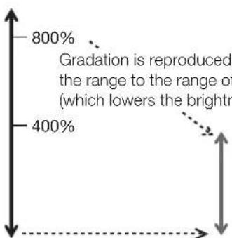 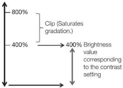 | ||
| Item Setting Options (underline indicates factory default) | |
| Input Transform Sets whether or not to apply ACES Input Transform to "3G-SDI RAW" signals ("ACESproxy (ver. 1.0.1)" is selected for "Picture Mode".Automatic: Applied automatically.Off: Not applied. | |
| Output Transform | This is displayed instead of "Gamma/EOTF" and "Color Gamut" when "ACESproxy (ver. 1.0.1)" is selected for "Picture Mode".ITU-R BT.709, ITU-R BT.2020, DCI-P3: ACESproxy is converted into respective mode. |
| Output Transform Surround | This is displayed instead of "Gamma/EOTF" and "Color Gamut" when "ACESproxy (ver. 1.0.1)" is selected for "Picture Mode".Dim Surround: Enables Dim Surround process specified by ACESproxy.Dark Surround: Enables Dark Surround process specified by ACESproxy. |
| Item Setting Options (underline indicates factory default) | |||
| Color Range Sets the quantization range.Automatic: Sets the range based on signal information automatically.When "Color Range" is set to "Normal" (97)Full, SDI Full (4-1019), LimitedWhen "Color Range" is set to "Compatible" (97)Full (0-1023), SDI Full (4-1019), Limited 1 (64-940), Limited 2 (64-1023)NoteSetting is disabled when "ACESproxy (ver. 1.0.1)" is selected for "Picture Mode".Operations when "Automatic" is selected are described below.- It is set in accordance with the settings if Color Range settings are included in the camera metadata. When there is "Full Range" metadata in Payload when SDI is selected, it will be set to "SDI Full".- When HDMI is selected, "Full" or "Limited" ("Full (0-1023)" or "Limited 1 (64-940)") is automatically set according to the HDMI signal information.- When SDI is selected, the setting is configured according to the settings for Picture Mode, Color Gamut, and Gamma/EOTF. | |||
| Setting Options | Color Range to be Set | ||
| "System Settings" → "Compatible Settings" → "Color Range" | |||
| When "Normal" | When "Compatible" | ||
| Picture Mode DCI-P3 | Full Full (0-1023) | ||
| Color Gamut | DCI-P3 | ||
| Cinema Gamut to DCI | |||
| DCI-P3+ to DCI | |||
| Gamma/EOTF | Canon Log (HDR) | ||
| Canon Log 2 (HDR) | |||
| Canon Log 3 (HDR) | |||
| S-Log2 (HDR) | |||
| S-Log3 (HDR) | |||
| Canon Log | Limited | Limited 2 (64-1023)Canon Lo | |
| Canon Log 3 | |||
| Other than the above Limited 1 (64-940) | |||
| Operations when "Format" is set to "ICtCp" are described below.- When "Color Range" is set to other than "Full", "Wave Form Monitor" will display only a signal set with "Color Range".- If "Channel Settings" → "Picture Mode" → "Type" is "L/R", the right screen's "Color Range" setting for the following will be the same as set for the left screen:- When displaying a single terminal's input in full-screen- When displaying "2 Sample Interleave" or "Dual Link 3G-SDI" signals | |||
| CDL/User LUT | Configures settings for CDL or User LUT.CDL/User LUT: Select a preset such as CDL or external LUT.CDL 1 to CDL 8, User LUT 1 ~ User LUT 8, OffOnly when "Picture Mode" is set to "User 1-7"ARRI (Rec2100-PQ-1K-100),ARRI (Rec2100-HLG-1K-200),VARICAM (V-Log to V-709), 2020 PQ to 2020 SDR, 2020 PQ to 709 SDR,2020 HLG to 709 HLG, 2020 HLG to 709 SDRPower: Adjusts the Gamma of the image. (0.01 increments)0.50 to 4.00 (1.00)Saturation: Adjusts the color saturation of the image. (0.001 increments)0.000 to 2.000 (1.000)Offset: Adjusts the black level of the image. (0.001 increments)-1.000 to 1.000 (0.000)Slope: Adjusts the white level of the image. (0.001 increments)0.000 to 2.000 (1.000)CDL/User LUT Bypass:When "CDL" is selected: When set to "On", you can temporarily disable the CDL adjustment result and return to previously set image quality.When "User LUT" is selected: When set to "On", you can return to the image quality before user LUT was applied.On, Off ____Detail SettingsCDL Export: Exports CDL parameters.CDL Preset (CDL 1 to CDL 8, All ), File Type (CCC, CDL), ExecuteCDL Import: Imports CDL parameters.Filename, CDL Preset (CDL 1 to CDL 8), ExecuteCDL Preset Name: You can specify the name of preset mode within 16 one-byte characters including alphabetical characters, numbers, and symbols.Anchor CDL: You can temporarily save parameters for "Power", "Saturation", "Offset", and "Slope" and recover the values. (anchor point setting)Reset CDL: Resets CDL parameters.NoteWhen a setting other than "CDL 1-8" is selected, the following functions cannot be set.- "Power", "Saturation", "Offset", "Slope", "Detail Settings", "Anchor CDL", "Reset CDL".When "ARRI (Rec2100-PQ-1K-100)" is selected, "HDR Range"→ "SMPTE ST 2084 (PQ)" settings become "1000".When "ARRI (Rec2100-HLG-1K-200)" is selected, "HDR Range"→ "Hybrid Log-Gamma" settings become "1000". | ||
| CDL/User LUT | ·Depending on the "User LUT" settings, "Color Gamut" and "Gamma/EOTF" will be the same as set below. | ||
| User LUT Color Gamut Gamma/EOTF | |||
| ARRI (Rec2100-PQ-1K-100) ITU-R BT.2020 SMPTE ST 2084 (PQ) | |||
| ARRI (Rec2100-HLG-1K-200) ITU-R BT.2020 Hybrid Log Gamma | |||
| VARICAM (V-Log to V-709) ITU-R BT.709 2.2 | |||
| 2020 PQ to 2020 SDR ITU-R BT.2020 | 2.4 | ||
| 2020 PQ to 709 SDR ITU-R BT.709 | |||
| 2020 HLG to 709 HLG ITU-R BT.709 | — | ||
| 2020 HLG to 709 SDR ITU-R BT.709 2.4 | |||
| ·"CDL/User LUT Bypass": Fixed at "Off" when "Picture Function Settings"> "Compare View" > "Enable" is set to "On". | |||
| Detail Settings | Sets details for Picture Mode. | ||
| Boost Contrast | You can increase the brightness.The upper limit for "Contrast" settings vary depending on the "Boost Contrast" settings.On: The settings for "Contrast" are from 1500 to 4000.Off: The settings for "Contrast" are from 0 to 1500.NoteIt is not possible to set the function after selecting Picture Mode when the right screen is selected. The right screen's setting will be the same as set for the left screen.When "Off" is selected, "HDR/SDR View" also becomes "Off". | ||
| LUT Import | You can import LUT. File names that can be imported can be up to 48 one-byte characters, including alphabetical characters, numbers, and symbols (including file extensions).Filename: Select a filename.LUT Type (User LUT, Gamma LUT, Gamut LUT): Select the LUT type.Select LUT: Selects User LUT/Gamma LUT/Gamut LUT 1-8.Base Color Gamut (SMPTE-C, EBU, ITU-R BT.709, Adobe RGB, DCI-P3, Native): Selects the color gamut used when creating the LUT (when "Gamut LUT" under "LUT Type" is selected).Execute: Performs import. | ||
| LUT Name | You can specify the name of LUT within one-byte 24 characters including alphabetical characters, numbers, and symbols.LUT Type (User LUT, Gamma LUT, Gamut LUT): Select the LUT type.Select LUT: Selects User LUT/Gamma LUT/Gamut LUT 1-8.Input Name: Input the LUT name. | ||
| LUT Delete | Deletes imported LUT.LUT Type (User LUT, Gamma LUT, Gamut LUT): Select the LUT type.Select LUT: Selects User LUT/Gamma LUT/Gamut LUT 1-8.Delete: Deletes LUT. | ||
| YCbCr Color Matrix | Sets the matrix conversion method for input signals in YCbCr format.Automatic: Matrix coefficient is set in conformance with the ITU-R BT.2020 standard when the "Picture Mode" or "Color Gamut" setting is "ITU-R BT.2020" and in conformance with the ITU-R BT.709 standard otherwise.ITU-R BT.709: Matrix coefficient is set in conformance with the ITU-R BT.709 standard.ITU-R BT.2020: Matrix coefficient is set in conformance with the ITU-R BT.2020 standard. | ||
| 2020 Constant LuminanceSets the color matrix conversion method to be used when "ITU-R BT.2020" is selected for "Picture Mode" or "Color Gamut".Constant Luminance: YUV signals are linearly converted and then converted into RGB signals.Non-constant Luminance: YUV signals are converted into RGB signals without changing gamma 0.45.NoteSD-SDI is fixed to "Non-constant Luminance".If "Channel Settings" > "Picture Mode" > "Type" is "L/R", "2020 Constant Luminance" is fixed at "Non-constant Luminance" for the following. However, if "Color Gamut" for the left and right screens is "ITU-R BT.2020", then the right screen's setting will be the same as set for the left screen.- When displaying a single terminal's input in full-screen- When displaying "2 Sample Interleave" or "Dual Link 3G-SDI" signals | |||
| 2020 Gamut MappingSet this item when "ITU-R BT.2020" is selected for "Picture Mode" or "Color Gamut".Gamut Mapping: Mapping is performed on colors outside the native color gamut by Canon's unique method.Clipping: Colors outside the native color gamut are clipped by a general method. | |||
| Hybrid Log-Gamma SystemSets the system gamma or peak luminance when selecting "Hybrid Log-Gamma" or "Hybrid Log-Gamma RGB" in "Gamma/EOTF".Automatic: When "Hybrid Log-Gamma" is selected, it adjusts the system gamma automatically to match the contrast value. It cannot be set when "Hybrid Log-Gamma RGB" is selected.Manual: Operations for when "Hybrid Log-Gamma" or "Hybrid Log-Gamma RGB" is selected are as follows:When "Hybrid Log-Gamma" is selected: Adjusts the system gamma.1.000 to 1.500 (1.200, 0.005 increments)When "Hybrid Log-Gamma RGB" is selected: Sets the peak luminance. The maximum value for each setting becomes the upper limit value of "HDR Range". 1.2 - 1000 cd/m^2 , 1.2 - 2000 cd/m^2 | |||
| HDR/SDR View The HDR (High Dynamic Range) and SDR (Standard Dynamic Range) displays can be compared.On: "Contrast" in the screen on the right is adjusted to the brightness for SDR.Off: Does not compare the HDR and SDR display.NoteThis cannot be set when the "Picture Mode" setting for the left and right screens is the same.When "On" is selected, "Boost Contrast" also becomes "On". | |||
| CalibrationPerforms calibration based on set target values when "User 1-7" is selected for "Picture Mode".Luminance: Sets the target luminance.48 to 150 (100) cd/m2Color Temperature: Sets the target color temperature.D93, D65, D61, D60, D56, D50, DCI-P3: Select from preset color temperatures.Custom (xy): You can adjust CIE x, y in increments of 0.001.x: 0.260 to 0.360 (0.313)/y: 0.260 to 0.360 (0.329)Color Gamut: Sets the color gamut.SMPTE-C, EBU, ITU-R BT.709, ITU-R BT.2020, Adobe RGB, DCI-P3Gamma: Sets the target gamma.2.2, 2.35, 2.4, 2.6, ITU-R BT.1886Start: Performs calibration.NoteWhen "Luminance" is set to high brightness, it may be calibrated beyond the brightness adjustment range and set lower than the target value, depending on the "Color Temperature" setting. In that case, set the "Luminance" again.Calibration cannot be executed in "Picture Mode" for the right screen. | |||
| Item Setting Options (underline indicates factory default) | ||
| HDMI Link | When "User 1-7" is selected for "Picture Mode", video is displayed at the image quality linked to the video image quality setting using the HDMI metadata.Automatic AdjustmentOn, OffColor Gamut/Gamma/EOTF: Matches the "Color Gamut" and "Gamma/EOTF" settings of the video display with the HDMI metadata.On, OffContrast/HDR Range: Matches the "Contrast", "HDR Range", and "Boost Contrast" setting of the video display with the HDMI metadata.On, OffNoteParameter of HDMI metadata and Video Display | |
| HDMI metadata Video display setting | ||
| Color Gamut BT.709 ITU-R BT.709 | ||
| BT.2020 ITU-R BT.2020 | ||
| Traditional SDR 2.2 | ||
| PQ PQ | ||
| Hybrid Log-Gamma Hybrid Log-Gamma | ||
| Cannot set "HDMI Link" when "Channel Settings"→ "Picture Mode" → "Type" is "L/R". | ||
| Copy Picture Mode | When "User 1-7" is selected for "Picture Mode", the content of the selected picture mode is copied. The following modes can be selected:Picture Mode (Copy from): SMPTE-C, EBU, ITU-R BT.709, ITU-R BT.2020, Adobe RGB, DCI-P3, User 1-7 (other than the currently set parameter)Execute: Performs copy.NoteIn "Picture Mode" other than "User 1-7", the results of calibration performed at the factory are copied. | |
| Picture Mode Name | You can change the name of "User 1-7" within 24 characters including alphabetical characters, numbers, and symbols. | |
| Anchor Adjustment | Temporarily saves parameters for adjusting "Contrast", "Brightness", "Chroma", "Sharpness", and "HDR Range" and recover the values (anchor point setting).OK: Performs anchor point setting.Cancel: Returns to the previous screen without setting anchor point. | |
| Reset | Return "Picture Mode" to factory default. Note that in "User 1-7" mode where you are performing calibration, the setting returns to the value after calibration instead of the factory default.When selected, the message "Reset Adjustment settings to defaults?" appears.OK: Performs reset.Cancel: Returns to the previous screen without resetting. | |
The factory default settings for each "Picture Mode" is as follows:
| Item SMPTE-C EBU | ITU-RBT.709 | ITU-RBT.2020 | AdobeRGB | DCI-P3 | |||
| Contrast 10001000100010001000480 | |||||||
| Brightness 000000 | |||||||
| Chroma 100010001000100010001000 | |||||||
| Sharpness 000000 | |||||||
| Backlight Control Local Dimming High | |||||||
| Color Temperature | Preset D65 | D65 D65 D65 | D65 DCI-P3 | ||||
| x 0.313 0.313 | 0.313 0.313 | 0.313 0.314 | |||||
| y 0.329 0.329 | 0.329 0.329 | 0.329 0.351 | |||||
| Gain R/G/B | 1023/1023/1023 (When "D65 Custom": 1000/1023/1023) | ||||||
| Bias R/G/B | 000000 | ||||||
| Color Gamut | SMPTE-C | EBU | ITU-R BT.709 | ITU-R BT.2020 | Adobe RGB | DCI-P3 | |
| Gamma/EOTF | 2.2 | 2.35 | 2.2 | 2.2 | 2.2 | 2.6 | |
| Color Range | Automatic | Automatic | Automatic | Automatic | Automatic | Automatic | |
| Input Transform | - | - | - | - | - | - | |
| Output Transform | - | - | - | - | - | - | |
| Output Transform Surround | - | - | - | - | - | - | |
| CDL/User LUT | Off | Off | Off | Off | Off | Off | |
| Boost Contrast | Off | Off | Off | Off | Off | Off | |
| YCbCr Color Matrix | Automatic | Automatic | Automatic | Automatic | Automatic | Automatic | |
| 2020 Constant Luminance | Non-constant Luminance | Non-constant Luminance | Non-constant Luminance | Non-constant Luminance | Non-constant Luminance | Non-constant Luminance | |
| 2020 Gamut Mapping | Clipping | Clipping | Clipping | Clipping | Clipping | Clipping | |
| Hybrid Log-Gamma System | - | Manual (when "Hybrid Log-Gamma": 1.200; when "Hybrid Log-Gamma RGB": y1.2-1000 cd/m2) | - | ||||
| HDR/SDR View | Off | Off | Off | Off | Off | Off | |
| HDMI Link | Off | Off | Off | Off | Off | Off | |
| Picture Mode Name | - | - | - | - | - | - | |
| Item User 1 User | 2 User 3 User 4 | User 5-7 | ||||
| Contrast 4000400040004000 | 01000 | |||||
| Brightness 00000 | ||||||
| Chroma 1000100010001000 | 01000 | |||||
| Sharpness 00000 | ||||||
| Backlight Control Local Dimming High | ||||||
| Color Temperature | Preset D65 | D65 DCI-P3 D65 | D65 | |||
| x 0.313 0.313 | 3 0.314 0.313 | 0.313 | ||||
| y 0.329 0.329 | 0.351 0.329 | 0.329 | ||||
| Gain R/G/B | 1023/1023/1023 (When "D65 Custom": 1000/1023/1023) | |||||
| Bias R/G/B | 00000 | |||||
| Color Gamut | ITU-R BT.2020 | ITU-R BT.2020 | DCI-P3 | DCI-P3 | ITU-R BT.709 | |
| Gamma/EOTF | SMPTE ST 2084 (PQ) | Hybrid Log-Gamma | SMPTE ST 2084 (PQ) | SMPTE ST 2084 (PQ) | 2.2 | |
| Color Range | Automatic | Automatic | Automatic | Automatic | Automatic | |
| Input Transform | - | - | - | - | - | |
| Output Transform | - | - | - | - | - | |
| Output Transform Surround | - | - | - | - | - | |
| CDL/User LUT | Off | Off | Off | Off | Off | |
| Boost Contrast | On | On | On | On | Off | |
| YCbCr Color Matrix | Automatic | Automatic | Automatic | Automatic | Automatic | |
| 2020 Constant Luminance | Non-constant Luminance | Non-constant Luminance | Non-constant Luminance | Non-constant Luminance | Non-constant Luminance | |
| 2020 Gamut Mapping | Clipping | Clipping | Clipping | Clipping | Clipping | |
| Hybrid Log-Gamma System | Manual (when "Hybrid Log-Gamma": 1.200; when "Hybrid Log-Gamma RGB": γ1.2-1000 cd/m2) | |||||
| HDR/SDR View | On | On | On | Off | Off | |
| HDMI Link | Off | Off | Off | Off | Off | |
| Picture Mode Name | User 1 (2020 PQ) | User 2 (2020 HLG) | User 3 (DCI PQ) | User 4 (DCI PQ D65) | User 5 to User 7 | |
| Item CINEMA EOS | SYSTEM ACESproxy (ver. 1.0.1) | ||
| Contrast 4000480 | |||
| Brightness 00 | |||
| Chroma 10001000 | |||
| Sharpness 00 | |||
| Backlight Control Local Dimming High | |||
| Color Temperature | Preset D65 D60 | ||
| x 0.313 0.322 | |||
| y 0.329 0.338 | |||
| Gain R/G/B 1023/1023/1023 (When "D65 Custom": 1000/1023/1023) | |||
| Bias R/G/B | 00 | ||
| Color Gamut | ITU-R BT.2020 | - | |
| Gamma/EOTF | Canon Log 2 (HDR) | - | |
| Color Range | Automatic | - | |
| Input Transform | - | Automatic | |
| Output Transform | - | DCI-P3 | |
| Output Transform Surround | - | Dark Surround | |
| CDL/User LUT | Off | Off | |
| Boost Contrast | On | Off | |
| YCbCr Color Matrix | Automatic | Automatic | |
| 2020 Constant Luminance | Non-constant Luminance | Non-constant Luminance | |
| 2020 Gamut Mapping | Clipping | Clipping | |
| Hybrid Log-Gamma System | Manual (when "Hybrid Log-Gamma": 1.200; when "Hybrid Log-Gamma RGB": y1.2-1000 cd/m2) | - | |
| HDR/SDR View | Off | Off | |
| HDMI Link | Off | Off | |
| Picture Mode Name | - | - | |
Channel Settings
This menu is used for input related settings. Select the "Select Channel" and choose a channel number from CH1 to CH30. Finally define the parameter of each of the "Channel Settings".
◆ Supported Signal Format (1105)
| Item Setting Options | |
| Select Channel | Display the channel number. In addition, you can assign each content of "Channel Settings" to each channel (30).CH1 to CH30NoteIt may take 5 seconds when switching channels. |
| Input Configuration Select the input. Factory default depend on the channel (64).3G/HD-SDI, 3G-SDI RAW, SD-SDI, HDMI, — (Not set) | |
| Select Input Signal Sets the signal display method (15).Automatic: The display method is automatically determined to match the input signal.Quad Input: Four input signals (Input A to Input D) are displayed.Dual Input A,B: Two input signals (Input A terminal and Input B terminal) are displayed.Dual Input C,D: Two input signals (Input C terminal and Input D terminal) are displayed.Single Input A, Single Input B, Single Input C, Single Input D: One input signal (any of Input A to Input D) is displayed.NoteSettings that can be set differ according to the input signal.- SD-SDI: Only "Single Input A" to "Single Input D" can be selected.- HDMI: This is fixed to "Automatic". | |
| Image Division | Sets the display method when the input signal is "3G/HD-SDI" and "Select Input Signal" is "Quad Input" or "Dual Input." Two division methods "Square Division" and "2 Sample Interleave" are supported for 4K video signals." "Quad Input"Automatic: Automatically determined based on payload and displayed.Square Division: Displays a signal transmitted over four inputs as a single image.2 Sample Interleave: Displays a signal transmitted divided into a 2K/HD signal as a single image.Multi View (Quad): Displays the video of each of the four inputs in four screens." "Dual Input A,B" or "Dual Input C,D"Automatic: Automatically determined based on payload and displayed.Square Division: Displays a signal transmitted over four inputs as a single image.2 Sample Interleave: Displays a signal transmitted divided into a 2K/HD signal as a single image.Dual Link 3G-SDI: Displays a Dual Link 3G-SDI signal as a single image.Multi View (Dual): Displays the video of each of the two inputs (Input A,B or Input C,D) in two screens.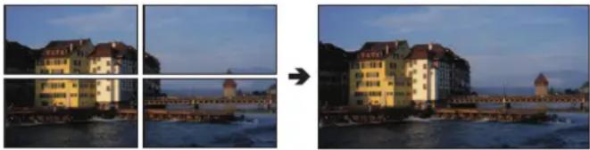 Select Input Signal: Quad Input, Image Division: Square Division Select Input Signal: Quad Input, Image Division: Square Division |
| Link Order | Automatically detects and displays correct terminal order based on payload when using "2 Sample Interleave" or "Dual Link 3G-SDI".Automatic, Off |
| Format Sets the color format and gradation.■ SDI SignalAutomatic, 4:2:2 YCbCr 10-bit, 4:2:2 YCbCr 12-bit, 4:4:4 YCbCr 10-bit,4:4:4 YCbCr 12-bit, 4:2:2 ICtCp 10-bit, 4:2:2 ICtCp 12-bit, 4:4:4 ICtCp 10-bit,4:4:4 ICtCp 12-bit, 4:4:4 RGB 10-bit, 4:4:4 RGB 12-bit, 4:4:4 XYZ 10-bit, 4:4:4 XYZ 12-bit■ HDMI SignalAutomatic, 4:4:4 XYZ 12/10-bitNoteThe HD-SDI signal is either "4:2:2 YCbCr 10-bit" or "4:2:2 ICtCp 10-bit"."SD-SDI" is fixed to "4:2:2 YCbCr 10-bit".For "3G-SDI RAW", the setting is fixed to "Automatic".The settings for correctly displaying ICtCp format signals are as follows.- "Picture Mode": "ITU-R BT.709" or "ITU-R BT.2020"- "Color Gamut": "ITU-R BT.709" or "ITU-R BT.2020"- "Gamma/EOTF": "SMPTE ST 2084 (PQ)", "Hybrid Log-Gamma" or "Hybrid Log-Gamma RGB"If you need to use the ICtCp format for SDI signals, select any of the following to match the signal: "4:2:2 ICtCp 10-bit", "4:2:2 ICtCp 12-bit", "4:4:4 ICtCp 10-bit", "4:4:4 ICtCp 12-bit"If "Automatic" is selected, they are rendered in a Payload that is selected in the order A> B > C → D.To use 4:4:4 XYZ 10-bit for SDI signals, select "4:4:4 XYZ 10-bit". Then, signals will be processed as signals where XYZ data is included in RGB data output in 4:4:4 RGB 10-bit format. | |
| Audio Input | Sets the audio terminal. Terminals that can be selected differ according to the setting of "Select Input Signal."When "Quad Input": Automatic, Input A, Input B, Input C, Input DWhen "Dual Input A,B": Automatic, Input A, Input BWhen "Dual Input C,D": Automatic, Input C, Input DAutomatic: Sets automatically to match the input signal.NoteThis setting is fixed at "Automatic" when "Select Input Signal" is "Automatic" or "Single Input". |
| Marker/TC/Cameralinfo Input | Set the target terminal so that various markers (except Grid Marker), Time Code, and Camera Information are displayed. (Camera Information is available in the "Multi View (Quad)" display only)When "Automatic" or "Quad Input": Input A, Input B, Input C, Input DWhen "Dual Input A,B": Input A, Input BWhen "Dual Input C,D": Input C, Input DNoteThis setting becomes invalid except for the "Multi View (Quad)" or "Multi View (Dual)" display. |
| Internal Sync Sets whether to synchronize four inputs when "Square Division" is selected.On: Force synchronization.Off: Do not force synchronization. | |
| Channel Name Sets the name of the selected channel. You can input up to 16 alphanumeric characters. | |
| Picture Mode Set "Picture Mode" by individual channel. | |
| Type Normal: Set one | "Picture Mode".Picture ModeL/R: Sets "Picture Mode" by individual left and right screen. Displays as "Single Input Dual View" when using resolutions of 2K or lower.Picture Mode L, Picture Mode R4K/2K: Sets "Picture Mode" by individual 4K or 2K signal screen.Resolution 4K, Resolution 2KAutomatic: "Picture Mode" is set according to the SDI signal. The set "Picture Mode" is changed to in the order camera metadata → Payload → resolution (4K/2K).Resolution 4K, Resolution 2K, Payload UHD/PQ, Payload UHD/HLG, Payload UHD, Payload 709/PQ, Payload 709/HLG, Payload 709, Payload VANC, Payload Unknown, Camera CINEMA EOS SYSTEM, Camera ARRI, Camera VARICAMNoteSettings that can be set differ according to the input signal."SD-SDI": "Type" is fixed to "Normal". "Automatic" cannot be set."3G-SDI RAW" and "HDMI": "Automatic" and "4K/2K" cannot be set in "Type".When "Type" is→ "L/R"- Setting the same "Picture Mode" for both left and right screens will cause "Picture Mode" in the non-selected screen to change to a different mode (for example, the "Picture Mode" settings of the left and right screens are switched).When using a signal 2K or under, it is fixed at "Single Input Dual View". (For example, the "Picture Mode" settings of the left and right screens are switched.) |
| Picture Mode Set the "Picture Mode" for each screen.Picture Mode LPicture Mode RResolution 4KResolution 2KPayload UHD/PQPayload UHD/HLGPayload UHDPayload 709/PQPayload 709/HLGPayload 709Payload VANCPayload UnknownCamera CINEMA EOS SYSTEMCamera ARRICamera VARICAM | SMPTE-C, EBU, ITU-R BT.709, ITU-R BT.2020, Adobe RGB, DCI-P3, User 1 (2020 PQ), User 2 (2020 HLG), User 3 (DCI PQ), User 4 (DCI PQ D65), User 5 ~ User 7, CINEMA EOS SYSTEM ACESproxy (ver. 1.0.1): Can be set when "Type" is "Normal".— (Not set): Cannot automatically change image quality to suit input signal. Can be set when other than "Resolution 4K" and "Resolution 2K" are selected in "Type" > "Automatic".Colorimetry Bit/Transfer Characteristics of the SDI Payload ID supports the signal in conformity with the following standard.SMPTE ST 425-1:2017 (3G-SDI Single Link / Square Division)SMPTE ST 425-3:2019 (3G-SDI Dual Link(2SI))SMPTE ST 425-5:2019 (3G-SDI Quad Link(2SI))SMPTE ST 292-1:2018 (HD-SDI) |
| Single Input Dual View When other than "Image Division" → "Multi View (Quad)" or "Multi View (Dual)", the image from the input signal can be reduced and shown in dual-screen.Automatic:When "Picture Mode" → "Type" is "L/R", or when the "Picture Function Settings" Sub Menu items are set to "On", identical images are automatically shown and dual-screen comparison can be made. 4K images are shown in reduced size.Relevant "Picture Function Settings" Sub Menu items:"Peaking", "False Color", "Over Range", "2020 Outside of Gamut View", "Monochrome", "Blue Only","Red Off", "Green Off", "Blue Off", and "Compare View"OffNoteCannot be used when unsupported video signal is input. | |
| Separator In the following cases, screen borders will be displayed.- When "Picture Mode" → "Type" is "L/R"- When "Multi View (Quad)" or "Multi View (Dual)" is selected- When "Single Input Dual View" is set to "Automatic" and the images are shown next to each other for image comparison- When "Picture Function Settings" → "Compare View" → "Enable" is "On"White, Half, Black, Off | |
The factory default settings for each channel is shown in the following table.
| CH CH1 CH2 CH3 CH4 CH5 | |||||
| Input Configuration 3G/HD-SD | HDMI 3G-SDI RAW 3G/HD-SDI 3G/HD-SDI | ||||
| Select Input Signal Automatic | Automatic Automatic Automatic Automatic | ||||
| Image Division Automatic Automatic Automatic | Automatic Automatic | ||||
| Link Order Automatic Automatic Automatic Automatic | Automatic Automatic | ||||
| Format Automatic Automatic | Automatic Automatic | ||||
| Audio Input Automatic Automatic Automatic Automatic | Automatic Automatic | ||||
| Marker/TC/Cameralinfo Input Input A Input A Input A Input A Input A | |||||
| Internal Sync | Off | Off | Off | Off | |
| Channel Name | (Blank) | (Blank) | (Blank) | (Blank) | |
| Picture Mode→ Type | Normal | Normal | Normal | 4K/2K | |
| Picture ModePicture Mode LResolution 4K | ITU-R BT.709 | ITU-R BT.709 | CINEMA EOS SYSTEM | User 1(2020 PQ) | |
| Picture Mode RResolution 2K | ITU-R BT.709 | ||||
| Payload | UHD/PQ | User 1 (2020 PQ) | |||
| UHD/HLG | User 2 (2020 HLG) | ||||
| UHD | ITU-R BT.2020 | ||||
| 709/PQ | — | ||||
| 709/HLG | — | ||||
| 709 | ITU-R BT.709 | ||||
| VANC | — | ||||
| Unknown | — | ||||
| Camera | CINEMAEOSSYSTEM | CINEMA EOS SYSTEM | |||
| ARRI | User 6 | ||||
| VARICAM | User 7 | ||||
| Single Input Dual View | Off | Off | Off | Automatic | |
| Separator | Off | Off | Off | Off | |
| CH CH6 CH7 CH8 CH9 CH10 to CH30 | ||||||
| Input Configuration 3G/HD-SDI | 3G/HD-SDI 3G/HD-SDI 3G/HD-SDI — (Not set) | |||||
| Select Input Signal Automatic | Automatic Automatic Automatic Automatic | |||||
| Image Division Automatic Automatic Automatic Automatic | Automatic Automatic Automatic | |||||
| Link Order Automatic Automatic Automatic Automatic Automatic | ||||||
| Format Automatic Automatic | Automatic Automatic Automatic | |||||
| Audio Input Automatic Automatic Automatic Automatic Automatic | ||||||
| Marker/TC/Cameralinfo Input Input A Input A Input A Input A Input A | ||||||
| Internal Sync OffOffOffOffOff | ||||||
| Channel Name | (Blank) | (Blank) | (Blank) | (Blank) | (Blank) | |
| Picture Mode → Type | L/R | 4K/2K | L/R | L/R | Normal | |
| Picture ModePicture Mode LResolution 4K | User 1(2020 PQ) | User 2(2020 HLG) | User 2(2020 HLG) | User 2(2020 HLG) | ITU-R BT.709 | |
| Picture Mode RResolution 2K | ITU-R BT.709 | |||||
| Payload | UHD/PQ | User 1 (2020 PQ) | ||||
| UHD/HLG | User 2 (2020 HLG) | |||||
| UHD | ITU-R BT.2020 | |||||
| 709/PQ | — | |||||
| 709/HLG | — | |||||
| 709 | ITU-R BT.709 | |||||
| VANC | — | |||||
| Unknown | — | |||||
| Camera | CINEMAEOSSYSTEM | CINEMA EOS SYSTEM | ||||
| ARRI | User 6 | |||||
| VARICAM | User 7 | |||||
| Single Input Dual View | Automatic | Automatic | Off | Automatic | Off | |
| Separator | Off | Off | White | Off | Off | |
Display Settings
This menu is used to configure the display method.
| Item Setting Options (underline indicates factory default) | |
| Screen Scaling | Defines how the video is scaled and displayed on the screen.Native Input Resolution: Displays the input signal without scaling.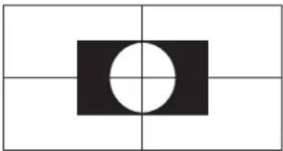 1920x1080 (original)200%: Doubles the vertical and horizontal dimensions. 1920x1080 (original)200%: Doubles the vertical and horizontal dimensions. 1920x1080→3840x2160Automatic: Enlarges to full screen. 1920x1080→3840x2160Automatic: Enlarges to full screen. 1920x1080→3840x2160NoteIn the following cases, the maximum magnification is 200% even if "Automatic" is selected.- When "Peaking", "False Color" or "Over Range" is "On" 1920x1080→3840x2160NoteIn the following cases, the maximum magnification is 200% even if "Automatic" is selected.- When "Peaking", "False Color" or "Over Range" is "On" |
| Anamorphic | Set when checking images photographed using an anamorphic lens. Displayed in accordance with the set magnification.x2.0, x1.8, x1.5, x1.33,OffNoteSettings are invalid in the following cases:- When "Peaking", "False Color" or "Over Range" is set to "On" |
| Scaling Method | Sets the interpolation method when "Screen Scaling" is set to "200%" or "Automatic".Shape Trace: Canon original processing that produces smooth slopes with reduced jagged lines. Bicubic: General interpolation process that uses neighboring pixel information to create interpolated pixels. Bicubic: General interpolation process that uses neighboring pixel information to create interpolated pixels. Nearest Neighbor: Process that uses nearest neighbor pixel information to create (copy) new pixels. This is useful as it enlarges the original pixels, thus making any jagged lines visible. Nearest Neighbor: Process that uses nearest neighbor pixel information to create (copy) new pixels. This is useful as it enlarges the original pixels, thus making any jagged lines visible. |
| Video Position(Multi View) | When displaying on two or four screens ("Multi View (Quad)" or "Multi View (Dual)" or "Single Input Dual View" display), set the vertical display position for the image."Top": Displays at the top of the screen."Middle": Displays at the top middle of the screen."Center": Displays at the middle of the screen.Top, Middle, Center |
| Zoom Enlarges part of the video image. The zoom function can be used when the resolution is "4096x2160", "3840x2160", "2048x1080" or "1920x1080".NoteThe zoom function cannot be used in the following cases:- During execution of "Playback File" under "Screen Capture"- During display of the test pattern- When calibration has been started.- When "Multi View (Quad)" or "Multi View (Dual)" is selected- When "Channel Settings" → "Picture Mode" → "Type" is set to "L/R"- When "Picture Function Settings" → "Compare View" → "Enable" is set to "On"While the zoom function is in use, the following are not displayed:Background Color, various markersWhen zoom settings are changed, "Frame Hold" turns "Off".When "Type"> "Normal" is selected: When the resolution is "2048x1080" or "1920x1080", the display position cannot be changed even if "Magnification" is set to "x2". | |
| Zoom Preset | Sets the zoom display method. There are three presets.Zoom 1, Zoom 2, Zoom 3, Off |
| Magnification Sets the display scale of zoom.x2, x4, x8 | |
| Position The zoom adjustment screen is displayed. Use the jog dial to adjust the display position. | |
| Type | Sets the enlarged image display method.Normal: Only displays the enlarged image.Single Input Dual View: Displays the overall image on the left and the enlarged image on the right.NoteWhen "Type"→ "Single Input Dual View" is selected: For 4K video (3840x2160 or 4096x2160), the quality of the enlarged image will be degraded compared to "Normal". |
| Frame Hold | Pauses the video.On,OffNoteSetting is disabled when "Peaking" is set to "On".If the image quality setting is changed while the video is paused, the setting may not change correctly. |
| Background Color | Sets the color of the black band to check the boundary of the black band and video image.White,Gray,OffNoteSetting is disabled when "Multi View (Quad)" or "Multi View (Dual)" is selected. |
| I/PsF | Defines how the interlace signal or PsF signal is displayed.Automatic: Automatically determined based on payload and displayed. If there is no payload, the signal is displayed as an interlace signal.Interlace: Displayed as an interlace signal.PsF: Displayed as a PsF signal. |
| PsF | Defines how the PsF signal is displayed.Progressive: Interpolates giving preference to image quality by detecting paired fields.Interlace: Interpolates using two adjacent fields giving priority to speed. |
| I/P Conversion | Sets the interlaced signal I/P conversion method.Image Priority: This mode gives priority to image quality. Processing time will be longer than "Speed Priority".Speed Priority: This mode gives priority to speed. |
| Film Cadence | Sets the film cadence mode.2-2: Displays progressive image after conversion for 2-2 pulldown processed interlaced signal input.2-3: Displays progressive image after conversion for 2-3 pulldown processed interlaced signal input.2-3-3-2: Displays progressive image after conversion for 2-3-3-2 pulldown processed interlaced signal input.Off: Does not perform film cadence mode progressive conversion.NoteThis can be set only when "I/P Conversion" is set to "Image Priority".Cannot be set in the "Multi View (Quad)" or "Multi View (Dual)" display. The setting is fixed to "Off". |
Audio Settings
This menu is used to set audio output from the headphone terminal.
| Item Setting | Options (underline indicates factory default) |
| SDI Group | Switches the audio group to be input during SDI audio input.CH1-CH8, CH9-CH16 |
| CH L/R (SDI) Sets | the audio to be output from the two channels (L/R) of the headphone respectively. The options differ according to the "SDI Group" setting.When "CH1-CH8" is selected for "SDI Group": CH1-CH8When "CH9-CH16" is selected for "SDI Group": CH9-CH16 |
| CH L/R (HDMI) Sets the audio to be output from the two channels (L/R) of the headphone respectively.CH1-CH8 | |
| Volume | Sets the volume.0 to 100 (30) |
| Audio Switch | Sets the stereo output.L R, L, R, MIX (L+R) |
Marker Settings
This menu is used to configure various markers.
| Item Setting Options (underline indicates factory default) | |
| Marker Preset | Customizes markers which are assigned to markers 1 to 5. Marker 1 to 5, Off |
| Aspect Marker "Aspect | Marker" displays a range in accordance with the specified aspect ratio.  Note "Aspect Marker" is not displayed in the following cases: When there is no signal, unsupported signal, or a channel with "Input Configuration" not set is selected When an enlarged image is displayed During the execution of "Playback File" under "Screen Capture" When a "Test Pattern" is displayed Note "Aspect Marker" is not displayed in the following cases: When there is no signal, unsupported signal, or a channel with "Input Configuration" not set is selected When an enlarged image is displayed During the execution of "Playback File" under "Screen Capture" When a "Test Pattern" is displayed |
| Enable | Switches the aspect marker On, Off. On, Off |
| Mask | Switches the mask color. Mask is the blanking area outside the range of the marker. Black:  Half (50% gray): Half (50% gray):  Off: Turns mask off. Off: Turns mask off. |
| Aspect Ratio | Sets the aspect ratio of the aspect marker. 16:9, 15:9, 14:9, 13:9, 4:3, 2.39:1, 2.35:1, 1.896:1, 1.85:1, 1.66:1, Variable The aspect ratio can be entered as a numeric value when you select "Variable" (0.01:1 increments). The grayed out slider becomes active and can be used to set the aspect ratio. 1.00:1 to 3.00:1 (1.78:1) |
| Line | Active when "Black" or "Half" is selected for "Mask". Switches lines on mask On, Off. On, Off |
| Line Width | Sets the thickness of the aspect marker line. Thick, Normal, Thin |
| Item Setting Options (underline indicates factory default) | ||
| Line Color | Sets the color of the aspect marker line. White, Red, Green, Blue, Yellow, Cyan, Magenta, Gray | |
| Line Brightness | Sets the brightness of the aspect marker line. High, Low, Half | |
| H Position | Changes horizontal position without changing the aspect. -65 to 65 (0) | |
| V Position | Changes vertical position without changing the aspect. -35 to 35 (0) | |
| Safety Zone Marker 1, 2 | There are two types of "Safety Zone Marker": 1 and 2, which share the same settings. A safety zone marker is used to set the safe zone of the image (actual displayed area) to check the image.  Note"Safety Zone Marker" is not displayed in the following cases:When there is no signal, unsupported signal, or a channel with "Input Configuration" not set is selectedWhen an enlarged image is displayedDuring the execution of "Playback File" under "Screen Capture"When a "Test Pattern" is displayed Note"Safety Zone Marker" is not displayed in the following cases:When there is no signal, unsupported signal, or a channel with "Input Configuration" not set is selectedWhen an enlarged image is displayedDuring the execution of "Playback File" under "Screen Capture"When a "Test Pattern" is displayed | |
| Shape | Sets the area shape of the safety zone marker. Box:  Brackets: Brackets:  Enclosure: Enclosure:  | |
| Line Width Sets the width of the safety zone marker line. Thick, Normal, Thin | ||
| Line Color | Sets the color of the safety zone marker line. White, Red, Green, Blue, Yellow, Cyan, Magenta, Gray | |
| Line Brightness | Sets the brightness of the safety zone marker line. High, Low, Half | |
| H Position | Adjusts the marker horizontal position with the set aspect and size. -65 to 65 (0) | |
| V Position | Adjusts the marker vertical position with the set aspect and size. -35 to 35 (0) | |
| Area Marker "Area Marker" is used to check a specific area using a rectangular box. | ||
 Note"Area Marker" is not displayed in the following cases:When there is no signal, unsupported signal, or a channel with "Input Configuration" not set is selectedWhen an enlarged image is displayedDuring the execution of "Playback File" under "Screen Capture"When a "Test Pattern" is displayed Note"Area Marker" is not displayed in the following cases:When there is no signal, unsupported signal, or a channel with "Input Configuration" not set is selectedWhen an enlarged image is displayedDuring the execution of "Playback File" under "Screen Capture"When a "Test Pattern" is displayed | ||
| Enable | Switches the area marker On, Off.On, Off | |
| H Position | Sets the start position (x-coordinate) to draw the rectangle (in increments of 2).0 to 4086 (240) | |
| V Position | Sets the start position (y-coordinate) to draw the rectangle (in increments of 2).0 to 2150 (120) | |
| Width (dot) | Sets the width of the rectangle (in increments of 2).10 to 4096 (240) | |
| Height (dot) | Sets the height of the rectangle (in increments of 2).10 to 2160 (120) | |
| Mask | Switches the mask color (in the marker).Black, Half, Off | |
| Line | Turns On/Off the outlines of the rectangular box.On, Off | |
| Line Width | Sets the width of the area marker line.Thick, Normal, Thin | |
| Line Color | Sets the color of the area marker line.White, Red, Green, Blue, Yellow, Cyan, Magenta, Gray | |
| Line Brightness | Sets the brightness of the area marker line.High, Low, Half | |
| Center Marker "Center Marker" shows the center of the image. | ||
| Enable | Switches the center marker On, Off.On,Off | |
| Size | Sets the size of the center marker.Large,Middle,Small | |
| Line Width | Sets the width of the center marker line.Thick,Normal,Thin | |
| Line Color | Sets the color of the center marker line.White,Red,Green,Blue,Yellow,Cyan,Magenta,Gray | |
| Line Brightness | Sets the brightness of the center marker line.High,Low,Half | |
| Grid Marker "Grid Marker" is marker used to check the horizontal and vertical position. | ||
| Enable | Switches the grid marker On, Off.On,Off | |
| Distance | Sets the horizontal and vertical line distance.160 dots,240 dots,320 dots | |
| Line Width | Sets the width of the grid marker line.Thick,Normal,Thin | |
| Line Color | Sets the color of the grid marker line. White,Red,Green,Blue,Yellow,Cyan,Magenta,Gray | |
| Line Brightness | Sets the brightness of the grid marker line.High,Low,Half | |
Function Settings
This menu is used to set the image signal information display and the cinema camera link function.
| Item Setting Options (underline indicates factory default) | |
Time Code Display the time code superimposed on the signal.  Note Settings of the video display that cannot be displayed, or input signal status (88) When "Multi View (Dual)" is displayed, the "H Offset" setting is invalid. Note Settings of the video display that cannot be displayed, or input signal status (88) When "Multi View (Dual)" is displayed, the "H Offset" setting is invalid. | |
| Enable | Switches the time code display On, Off.On, Off |
| Type | Selects the type.VITC, LTCNoteThis setting becomes invalid when HDMI signal is input and is fixed to "VITC". |
| Size | Selects the size.Large, Small |
| Position | Selects the display position.Top Left, Top Right, Bottom Left, Bottom RightNoteThis setting becomes invalid in the "Multi View (Dual)" display. |
| H Offset | Adjusts the display position of the time code.0 to 1460 (0) |
| Type String Display | Sets display of VITC/LTC strings.On, Off |
| Brightness | Sets the Brightness of the strings.Normal, Half |
| Audio Level Meter | Configures various settings for the audio level meter. Displays the audio level of the selected channel number.NoteSettings of the video display that cannot be displayed, or input signal status [88] |
| Enable | Switches the audio level meter On, Off.On,Off |
| Channel Number (SDI) | Sets the number of channels displayed when SDI signal is input. Options change according to the setting for "SDI Group" under "Audio Settings".When "CH1-CH8" is selected for "SDI Group": 2CH (CH1-CH2), 4CH (CH1-CH4),6CH (CH1-CH6), 8CH (CH1-CH8),8CH (1-4, 5-8) (CH1-CH8)When "CH9-CH16" is selected for "SDI Group": 2CH (CH9-CH10), 4CH (CH9-CH12),6CH (CH9-CH14), 8CH (CH9-CH16),8CH (1-4, 5-8) (CH9-CH16)NoteWhen "Channel Number (SDI)" is set to "8CH (1-4, 5-8)", if "Size" is set to "Large", the resulting display will be the same as for "8CH". |
| Channel Number (HDMI) | Sets the number of channels displayed when HDMI signal is input.2CH (CH1-CH2), 4CH (CH1-CH4), 6CH (CH1-CH6), 8CH (CH1-CH8) |
| Size | Sets the size of the display.Large,Middle, Small |
| Peak Hold | When set to "On", one second of audio signal at the peak is kept.On, Off |
| Reference Level | Sets the reference level.-40 to 0 (-20) |
| Brightness | Sets brightness for the audio level meter.Normal, Low, Half |
Wave Form Monitor Configures various settings for the wave form monitor. On the wave form monitor, the horizontal axis shows the horizontal resolution of the video and the vertical line shows the signal level. To the right of the wave form monitor, "Color Range" and "HDR Range" information (vertical line) is displayed.Signal level 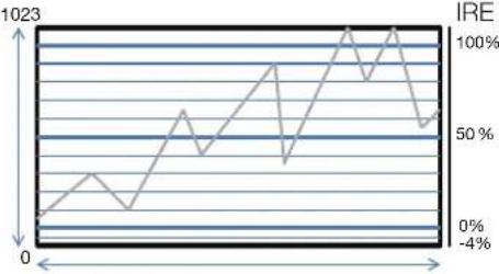 Horizontal resolution of videoNoteSettings of the video display that cannot be displayed, or input signal status [88] Horizontal resolution of videoNoteSettings of the video display that cannot be displayed, or input signal status [88] | |
| Enable | Switches the wave form monitor On, Off.On,Off |
| Item Setting Options (underline indicates factory default) | ||
| Select Signal | Sets the waveform to be displayed.Y, Cb, Cr, R, G, B | |
| Display Type | Sets the display type. When "Line" is selected, data for one line is displayed.All, LineSelects the line to be displayed when "Line" is selected.Select Line: 1 to 2160 | |
| Scale | Sets the scale of the wave form monitor.Automatic: Sets in accordance with the "Gamma/EOTF" and "Color Range" settings.IRE, ST 2084 (PQ) Full, ST 2084 (PQ) Limited, Hybrid Log-Gamma, Canon Log,Canon Log 2, Canon Log 3, S-Log2, S-Log3, ARRI (Rec2100-PQ-1K-100),ARRI (Rec2100-HLG-1K-200): Select the scale. | |
| Reference Line | A guide is displayed at the specified position. "Reference Line" is not displayed when "1023" is selected.4 to 1023 | |
| Reference Level | Sets the range of the reference level. Tints the outside of the range of the reference level.In the case of "Gamma/EOTF" corresponding to the HDR range, parts that exceed the HDR range are tinted.When "Color Range" > "Limited", outside the limited range is tinted.Automatic: Sets in accordance with the "Gamma/EOTF" and "Color Range" settings.Manual: When you select "Manual", sets the reference level.Reference Level High: Sets the reference display level (high). "Reference Level High" is not displayed when "1023" is selected.468 to 1023Reference Level Low: Sets the reference display level (low). "Reference Level Low" is not displayed when "0" is selected.0 to 468 | |
| Color | Sets the signals to be displayed and the color of signals exceeding the reference level.Y, Cb, Cr, R, G, B: Selects the signal.Selects the color of the selected signal.White, Red, Green, Blue, Yellow, Cyan, MagentaDefault value of each signal is shown below.Y (White), Cb (White), Cr (White), R (Red), G (Green), B (Blue)Reference Level High, Reference Level Low: Selects the reference level.White, Red, Green, Blue, Yellow, Cyan, MagentaDefault value of each reference level is shown below.Reference Level High (Magenta), Reference Level Low (Cyan) | |
| Position | Selects the display position.Bottom Left, Bottom RightNoteThis setting becomes invalid in the "Multi View (Dual)" display. | |
| Size | Sets the size of the display.Large, Middle, Small | |
Vector Scope Configures various settings for the vector scope. Vector scope displays the intensity of color signals and hue with the horizontal axis showing the color difference signal Cb and the vertical line showing Cr.(Cb, Cr) = (255, 255)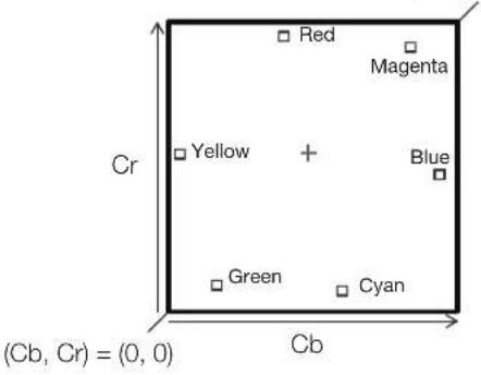 NoteSettings of the video display that cannot be displayed, or input signal status [88] NoteSettings of the video display that cannot be displayed, or input signal status [88] | ||
| Enable Switches the vector scope On, Off.On, Off | ||
| Target | Sets the target.75%, 100%, 75%+100% | |
| Position | Selects the display position.Bottom Left,Bottom RightNoteThis setting becomes invalid in the "Multi View (Dual)" display. | |
| Size | Sets the size of the display.Large,Middle, Small | |
Histogram Displays the luminance distribution of the video.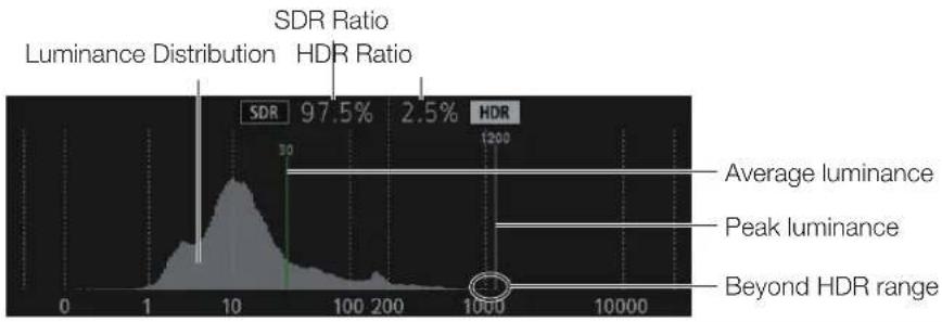 | ||
| Enable | Switches between displaying or hiding "Histogram".On,Off | |
| Item Setting Options (underline indicates factory default) | ||
| Color | Automatic: Unless "Picture Function Settings" → "False Color" → "Enable" is set to "Off", it will automatically adjust the display to match the "False Color" settings.Normal: Displays in monochrome.False Color: When "Gamma/EOTF" is set to → "SMPTE ST 2084 (PQ)" or "Hybrid Log-Gamma", then it will adjust the display to match the "False Color" settings.When "False Color" → "Enable" is "False Color 1" or "Off": Match the "False Color 1" settings.When "False Color" → "Enable" is "False Color 2": Match the "False Color 2" settings. | |
| Gain | Increases the displayed graph size.x1, x2, x3 | |
| HDR Range | On: Areas that exceed the HDR range will be tinted.On (Clip): Areas that exceed the HDR range and areas that exceed the HDR range and are clipped will be tinted.Off: Areas that exceed the HDR range will not be tinted. | |
| HDR/SDR Ratio | Switches between displaying or not displaying the "HDR/SDR Ratio" when "Gamma/EOTF" is set to "SMPTE ST2084 (PQ)" or "Hybrid Log-Gamma". The ratio calculation for HDR/SDR uses the "False Color" → "HDR/SDR Border" settings.On, Off | |
| Peak/Ave.Luminance | Switches between displaying or not displaying the "Peak/Ave. Luminance" when "Gamma/EOTF" is set to "SMPTE ST2084 (PQ)" or "Hybrid Log-Gamma".On, Off | |
| Size | Sets the size of the display.Large, SmallNoteFixed to "Small" during "Single Input Dual View". | |
| Frame Luminance Monitor | When "Gamma/EOTF" is set to "SMPTE ST 2084 (PQ)" or "Hybrid Log-Gamma", "Max./Ave. Luminance" for the entire screen (frame) is displayed. For other conditions, "Max./Ave. Gradation Values" is displayed. The frame luminance monitor can be used when the resolution is "4096x2160", "3840x2160", "2048x1080" or "1920x1080".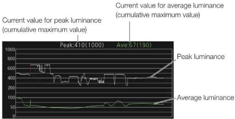 Luminance graph Luminance graph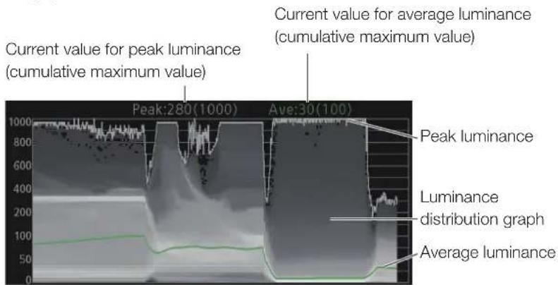 Ratio graph Ratio graph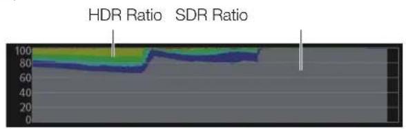 NoteSettings of the video display that cannot be displayed, or input signal status(188)The update time for "Frame Luminance Monitor" may take a long duration, or graph indication of "Frame Luminance Monitor" may be reset when displaying the "Frame Luminance Monitor" and operating the OSD menu. NoteSettings of the video display that cannot be displayed, or input signal status(188)The update time for "Frame Luminance Monitor" may take a long duration, or graph indication of "Frame Luminance Monitor" may be reset when displaying the "Frame Luminance Monitor" and operating the OSD menu. | |
| Enable | Sets "Frame Luminance Monitor" on or off. Obtains the luminance value when valid.On,Off | |
| Display | Sets whether each graph is displayed.All: Displays "Luminance Graph (Including luminance value)" and "HDR/SDR Ratio Graph".Luminance Graph: Displays "Luminance Graph (Including luminance value)".HDR/SDR Ratio Graph: Displays "HDR/SDR Ratio Graph".Luminance Value: Displays the peak and average luminance values.Off: Does not display any graphs. | |
| Item Setting Options (underline indicates factory default) | ||
| Luminance Graph Settings | Sets "Luminance Graph" display method. | |
| Luminance Distribution: Switches between displaying and not displaying the luminance distribution graph.On, OffColorAutomatic: Unless "Picture Function Settings"→ "False Color" → "Enable" is set to "Off", it will automatically adjust the display to match the "False Color" settings.Normal: Displays in monochrome.False Color: When "Gamma/EOTF" is set to "SMPTE ST 2084 (PQ)" or "Hybrid Log-Gamma", then it will adjust the display to match the "False Color" settings.When "False Color" → "Enable" is "False Color 1" or "Off": Match the "False Color 1" settings.When "False Color" → "Enable" is "False Color 2": Match the "False Color 2" settings.Reference Luminance Level - PeakAutomatic: Works in conjunction with the "HDR Range" settings to automatically tint the areas that exceed the peak luminance.Manual: Sets the upper limit for peak luminance. Areas that exceed the set value will be tinted.(400 to 4000: increments of 100, 4000 to 10000: increments of 1000)400 to 10000 (1000)Reference Luminance Level - Ave.: Areas that exceed the set value will be tinted.(Increments of 100)100 to 1000 (400)Reference Lum. Rise Level - Peak: Sets the peak luminance rise reference value. (Increments of 10 cd/m2)0 to 1000 (400)Reference Lum. Rise Level - Ave.: Sets the average luminance rise reference value. (Increments of 10 cd/m2)0 to 1000 (200) | ||
| HDR/SDR Ratio Graph Settings | Sets "HDR/SDR Ratio Graph" display method. The ratios for HDR and SDR use the "False Color" → "HDR/SDR Border" settings as well as the settings for each range.TypeHDR/SDR: Displays the ratio between the HDR and SDR areas.HDR: Displays the ratio of luminance in the HDR area.Scale: When "Type" is set to "HDR", sets the scale of the luminance value.Automatic, 100%, 75%, 50%, 25% | |
| Size | Sets the size of the display.Large, SmallNoteFixed to "Small" during "Single Input Dual View". | |
| Reset Resets the displayed content. | ||
| Export The luminance information obtained when "Frame Luminance Monitor" is valid, is exported to the USB memory. | ||
| Pixel Value Check | When "Gamma/EOTF" is set to "SMPTE ST 2084 (PQ)" or "Hybrid Log-Gamma", the luminance and RGB value of the specified pixel (cursor) position are measured and displayed. The pixel value check can be used when the resolution is "4096x2160", "3840x2160", "2048x1080" or "1920x1080".NoteSettings of the video display that cannot be displayed, or input signal status(□88)The update time for "Pixel Value Check" may take a long duration when displaying the "Pixel Value Check" and operating the OSD menu. | |
| Enable | Switches the "Pixel Value Check" On, Off.On,Off | |
| H Position | Sets the pixel position (horizontal).1 to 4096 (960) | |
| V Position | Sets the pixel position (vertical).1 to 2160 (540) | |
| Reset Position | Sets operation when the RESET button is pressed.Normal: Resets the value to the default value.Around Peak Luminance: Moves closer to the area of peak luminance inside the display image. | |
| Test Pattern | Sets the test pattern built into the main unit.White (1023), White (940), Gray, Black (64), Black (0), Ramp, Color Bars,Color Bars (PQ Full), Color Bars (PQ Limited), Color Bars (HLG), PLUGE, PLUGE (PQ/HLG),OffNoteIf the power is turned off once and then back on, the test pattern will not be displayed.The test pattern will be erased in the following cases:- When calibration has been started- When a channel is changed using the CH button, F button assigned for Channel UP/Channel DOWN, or "Select Channel" under "Channel Settings"- When changing "Input Configuration" or "Select Input Signal" under "Channel Settings"- When "Reset All Settings" is executed | |
| Signal Monitoring Monitors | the input signal status.Note"Signal Monitoring" cannot be used in the following cases:- When "Single Input Dual View" is displayed- When an enlarged image is displayed- During display of the test pattern- During execution of "Playback File" under "Screen Capture"When an error is displayed, "In Monitor Display" will not be shown.The position the error is displayed can be adjusted with "In Monitor Display"> " Position". | |
| Control | Sets whether "Signal Monitoring" is used or not.On, Off | |
| Error Hold | Sets the length of time for displaying errors, when they are detected.On (No time out): Errors continue to be displayed. To hide the displayed error, press the RESET button when closing the OSD menu.On (5 sec.): The displayed error will disappear 5 seconds after the initial detection.Off: Only displays errors during the period when they are detected. The displayed error message will disappear once the error ends. | |
| No Signal/Unsupported Signal | Displays an error when there is no signal or the signal is not supported.On, Off | |
| 2SI Link Order | Displays an error when the cables inserted into the input terminals are in the wrong order when using signals input via "2 Sample Interleave".On, Off | |
| Error Log Displays error history. | ||
| Screen Capture Captures the screen. | ||
| Capture Captures the screen. The data is saved under the name "YYYYMMDD_hhhmmss.bmp" or "YYYYMMDD_hhhmmss.jpg" in the root folder of the USB memory. | ||
| Frame Hold | Pauses the video.On, Off | |
| Capture Source | Selects the sources to capture.All: Everything is captured including video assistance functions such as markers and wave form monitor as well as OSD menu.Video: Only video signals are captured. | |
| File Type | Sets the File Type of the image to capture.Bitmap, JPEG | |
| Create HDR/SDR Compare File | Creates a file that lets you compare the brightness of HDR and SDR images on a computer. When saving, [pc] is appended to the file name.On, Off | |
| Playback File Plays | back captured images.Select File: Selects a file.Execute: Plays back the image.NoteWhen playing back captured images on other DP-V2410 or PC, color may not be played back preciselyCannot replay HDR/SDR comparison images with [pc] in the file names. | |
| Finish Playback File | Finishes playback. | |
| Item Setting Options (underline indicates factory default) | ||||||
| Camera Link Sets the functions to link with Cinema EOS cameras and ARRI / Panasonic cinema cameras. | ||||||
| Automatic Adjustment (CINEMA EOS) | Sets whether or not to link to the camera's image quality setting when "CINEMA EOS SYSTEM" is selected for "Picture Mode". (When "Input Configuration" is "3G/HD-SDI" or "3G-SDI RAW")On, OffWhen "Color Gamut/Gamma/EOTF", "Color Temperature", and "Color Range" are all set to "On", the following settings are configured.Parameter of Cinema EOS cameras and DP-V2410 | |||||
| Cinema EOS cameras DP-V2410 | ||||||
| Color Space Color Gamut Color Temperature | ||||||
| BT.709 ITU-R BT.709 D65 | ||||||
| BT.2020 ITU-R BT.2020 D65 | ||||||
| DCI-P3 DCI-P3 | DCI-P3 | |||||
| DCI-P3+ DCI-P3+ to 709 D65 | ||||||
| DCI-P3+ to DCI-P3 | ||||||
| Cinema Gamut | Cinema Gamut to 709 | |||||
| Cinema Gamut to 2020 | ||||||
| Cinema Gamut to DCI-P3 | ||||||
| RAW Gamut | Cinema Gamut to 709 | |||||
| Cinema Gamut to 2020 | ||||||
| Cinema Gamut to DCI-P3 | ||||||
| Cinema EOS cameras DP-V2410 | ||||||
| Gamma/EOTF | Gamma/EOTF | |||||
| Canon Log | Canon Log (HDR) | |||||
| Canon Log 2 | Canon Log 2 (HDR) | |||||
| RAW Gamma | ||||||
| Canon Log 3 | Canon Log 3 (HDR) | |||||
| ST 2084, PQ | SMPTE ST 2084 (PQ) | |||||
| Normal (BT.709) | 2.2 | |||||
| Wide DR | ||||||
| EOS Std. | ||||||
| DCI-P3 | 2.6 | |||||
| Color Gamut/Gamma/EOTF: The image quality of the display corresponds to the camera's settings.On, OffColor Temperature: The image quality of the display corresponds to the camera's settings.On, OffDisplay Color Gamut: Sets the color gamut shown on the display when the camera's "Color Space" is set to "Cinema Gamut" or "DCI-P3+".ITU-R BT.709, ITU-R BT.2020, DCI-P3 | ||||||
| Automatic Adjustment (ARRI) | Sets whether or not to link to the camera's image quality setting when "User 6-7" is selected for "Picture Mode". (When "Input Configuration" is "3G/HD-SDI")On, OffParameter of ARRI Cinema camera and DP-V2410 | |||||
| ARRI Cinema camera | DP-V2410 | |||||
| Color Space | Display Color Gamut | CDL/User LUT | Color Gamut | Gamma/EOTF | ||
| REC 709 | —ITU-R | BT.709 | 2.2 — | |||
| REC 2020 | —ITU-R | BT.2020 | 2.2 — | |||
| Wide Gamut Log C | Rec2100-PQ-1K-100 | ARRI (Rec2100-PQ-1K-100) | ITU-R BT.2020 | SMPTE ST 2084 (PQ) | ||
| Rec2100-HLG-1K-200 | ARRI (Rec2100-HLG-1K-200) | ITU-R BT.2020 | Hybrid Log-Gamma | |||
| User LUT 1-8 | User LUT 1-8 — — | — | ||||
| User LUT: Sets the color gamut and gamma/EOTF shown on the display when "Automatic Adjustment (ARRI)" is set to "On".Rec2100-PQ-1K-100, Rec2100-HLG-1K-200, User LUT 1-8 | ||||||
| Automatic Adjustment (VARICAM) | Sets whether or not to link to the camera's image quality setting when "User 6-7" is selected for "Picture Mode". (When "Input Configuration" is "3G/HD-SDI")On, OffParameter of Panasonic Cinema camera and video display | |||||
| Panasonic Cinema camera | DP-V2410 | |||||
| Color Space | Display Color Gamut | CDL/User LUT | Color Gamut | Gamma/EOTF | ||
| V-709 — | — | ITU-R BT.709 | 2.2 — | |||
| V-Log | V-Log to V-709 | VARICAM (V-Log to V-709) | ITU-R BT.709 | 2.2 — | ||
| User LUT 1-8 | User LUT 1-8 — — | — | ||||
| User LUT: Sets the color gamut and gamma/EOTF shown on the display when "Automatic Adjustment (VARICAM)" is set to "On".V-Log to V-709, User LUT 1-8 | ||||||
| Anamorphic | When a Canon camera is connected, displays in accordance with the settings when anamorphic lens display settings are included in the camera metadata.On, Off | |||||
| Area Marker | When an ARRI cinema camera is connected to this device, the "H Position", "V Position", "Width", and "Height" for the "Area Marker" change depending on the metadata.ARRI Frame line 1A, ARRI Frame line 1B,OffNoteThis cannot be displayed when "Marker Preset" is "Off". | |||||
| Fan | Allows you to link stopping the fan to the camera's recording operation (For Cinema EOS cameras, Canon professional-use video cameras, or ARRI cinema cameras that are compatible with this video display). Set "Fan Control" under "System Settings" to "On".On, OffNoteAt a room temperature (25 °C), the fan remains off for approximately one minute when the AC power supply is used and ten minutes when the DC power supply is used. Select the type of power supply according to the purposes.If the temperature inside the main unit increases while the fan is off, the message "Fan will be rotated as the temperature is high." is displayed and the fan starts rotating approximately ten seconds later. Since the temperature of the main unit has increased, the fan rotates faster than usual.The video display's fan may start rotating earlier than the camera because the temperature inside the main unit has increased.The fan may not stop in some conditions, for example when used at a high temperature. | |||||
| Camera Information | Sets conditions to display camera information.Automatic: Camera information is displayed for 4 seconds when the information has changed.On: Camera information is always displayed.Off: Camera information is not displayed. | |||||
The information display functions that can be displayed vary depending on the video display's settings or the input signal status.
●: Can view —: Cannot view
| Time Code | Audio Level Meter | Wave Form Monitor | Vector Scope | Histogram | Frame Luminance Monitor | Pixel Value Check | |
| With an SD-SDI signal | ● | ● | ——— | —— | |||
| While zooming: When "Zoom"→ "Type" is set to "Normal" | ● | ● | ——— | —— | |||
| When "Frame Hold" is "On"(For progressive signals) | — | — | ● ● | ● ● | ● | ||
| When "Frame Hold" is "On"(For interlaced or PsF signals) | ——— | — | ● ● | ● | |||
| When "Peaking" → "Enable" is set to "Peaking 1" or "Peaking 2" | ● | ● | — | — | ● ● | ● | |
| During execution of "Playback File" under "Screen Capture" | ——— | ——— | |||||
| When the display position and "Audio Level Meter" to be displayed is the same | — | ● ● | ● ● | ● | |||
| When "Test Pattern" is displayed | ——— | ——— | |||||
| When "Multi View (Quad)" is displayed | ● | ● | ——— | —— | |||
| When "Multi View (Dual)" is displayed | ● ● | ● ● | ——— | ||||
| When "Single Input Dual View" is displayed | ● ● | ● ● | ● ● | — | |||
| When "Channel Settings" → "Picture Mode"→ "Type" is set to "L/R": When "Multi View (Dual)" or "Single Input Dual View" is displayed | ● ● | ● ● | ——— | ||||
| When "Channel Settings" → "Picture Mode"→ "Type" is set to "L/R", and when a single screen is being used | ● | ● | ——— | —— | |||
| When "Picture Function Settings" → "Compare View" → "Enable" is set to "On": When "Single Input Dual View" is set to "Off" and also the resolution is 4096x2160 or 3840x2160 | ● | ● | ——— | —— | |||
| When "Wave Form Monitor" is displayed: When "Wave Form Monitor" → "Select Signal" is "R", "G", "B" | ● ● | ● | — | ● ● | ● | ||
| When "Wave Form Monitor" is displayed and "Wave Form Monitor" → "Size" is "Large": When "Position" settings for "Wave Form Monitor" and "Vector Scope" are the same, or when using "Multi View (Dual)" / "Single Input Dual View" display | ● ● | ● | — | ● ● | ● | ||
| When an I/PsF 4K signal is displayed on one screen and when the "Wave Form Monitor" and "Vector Scope" "Position" settings are the same | ● ● | ● | — | ● ● | ● | ||
| When there is no signal or the input signal is not supported | ● ● | ● ● | ——— | ||||
| When displaying video at resolutions other than 4096x2160 / 3840x2160 / 2048x1080 / 1920x1080 | ● ● | ● ● | ——— |
Picture Function Settings
This menu is used to set video assistance functions, for example.
| Item Setting Options (underline indicates factory default) | |
| Peaking The outline is displayed in a color, used to check the focus. Customize "Peaking" and sets it to "Peaking 1" or "Peaking 2".Note"Peaking" cannot be displayed during the execution of "Playback File" under "Screen Capture".Cannot set when "Compare View"→ "Enable" is "On". | |
| Enable | Switches the peaking display mode and also sets peaking to Off.Peaking 1, Peaking 2,OffNote"Enable" changes to "Off" when the power is turned on again. |
| Monochrome | Displays video in monochrome.Peaking 1 (On, Off), Peaking 2 (On, Off) |
| Frequency | Sets the central frequency of contour enhancement signals.Peaking 1 (Low, Middle, High), Peaking 2 (Low, Middle, High) |
| Range | Sets the width of the range to be colored.-3 ~ 3 (0) |
| Color | Sets the color to be used.White, Red, Green, Blue, Yellow, Cyan, Magenta |
| False Color | Displays different colors for the video's brightness levels to make it easier to check the exposure and brightness distribution. Customize "False Color" and sets it to "False Color 1" or "False Color 2".Note"False Color" cannot be displayed during the execution of "Playback File" under "Screen Capture".Cannot set when "Compare View"→ "Enable" is "On". |
| Enable | Switches between False Color display mode and non-display.False Color 1, False Color 2,OffNote"Enable" changes to "Off" when the power is turned on again. |
| Type | Sets the tint color display method.Automatic: Sets in accordance with the "Gamma/EOTF" settings.IRE, SMPTE ST 2084 (PQ), Hybrid Log-GammaNoteWhen "IRE" in "Type" is selected, "HDR Range" settings become invalid. |
| HDR/SDR Border | Sets whether to tint the SDR/HDR areas.100, 200 |
| Item Setting Options (underline indicates factory default) | ||
| Range - SDR | Sets the upper limit for the SDR area.False Color 1 (On, Off), False Color 2 (On, Off)When "On" is selected, sets the size of the area to be colored. (increments of 10)Monochrome/Brown: 10 to 190 (90°) (40)Brown/Monochrome: 20 to 200 (100°) (80)* When "HDR/SDR Border" is "100" | |
| Range - HDR Sets the tint color range.False Color 1 (Automatic, Automatic (Over Range), Manual), False Color 2 (Automatic, Automatic (Over Range), Manual)Automatic: Sets the upper limit automatically in accordance with the "Gamma/EOTF" settings.When "Manual" or "Automatic (Over Range)" is selected, sets the size of the area to be colored.SMPTE ST 2084 (PQ): The settings are as follows. (100 to 1000: 10 increments, 1000 to 4000: 100 increments, 4000 to 10000: 1000 increments)Blue/light blue: 250 (150°) to 400Light blue/green: 400 to 1000Green/yellow: 600 to 4000Yellow/orange: 800 to 8000Orange/red: 1000 to 10000 (Only when using "Manual")Hybrid Log-Gamma: The settings are as follows. (10 increments)Blue/light blue: 250 (150°) to 300Light blue/green: 300 (200°) to 500Green/yellow: 400 (300°) to 700Yellow/orange: 500 (400°) to 900Orange/red: 600 (500°) to 1000 (Only when using "Manual")* When "HDR/SDR Border" is "100" | ||
| Over Range Displays video in monochrome, with the areas where the set range is exceeded are shown tinted. | ||
| Item Setting Options (underline indicates factory default) | |
| 2020 Outside of Gamut View | When "ITU-R BT.2020" is selected for "Picture Mode" or "Color Gamut", displays video in monochrome, with the areas where the color gamut exceeds the selected color gamut shown in red.NoteCannot set when "Compare View"→ "Enable" is "On". |
| Enable | Switches between On and Off for "2020 Outside of Gamut View".On,OffNote"Enable" changes to "Off" when the power is turned on again. |
| Color Gamut | Sets the "Color Gamut" to be set as out of color gamut.ITU-R BT.709, Native |
| Range | Sets the range when tinting dark areas. (1 increments)0 to 5120: Tints all dark areas.512: Dark areas at the set values or less are not tinted. |
| Monochrome | Video is displayed in monochrome.On,OffNoteCannot set when "Compare View"→ "Enable" is "On".When the power is turned off and on, becomes "Off". |
| Blue Only | Cuts red and green signals, and displays only blue signals in monochrome.On,OffNote"Blue Only" cannot be set when "CDL/User LUT" is a setting other than "CDL 1-8" or "Off".Cannot set when "Compare View"→ "Enable" is "On".When the power is turned off and on, becomes "Off". |
| Red Off | Video is displayed with red signals cut.On,OffNoteCannot set when "Compare View"→ "Enable" is "On".When the power is turned off and on, becomes "Off". |
| Green Off | Video is displayed with green signals cut.On,OffNoteCannot set when "Compare View"→ "Enable" is "On".When the power is turned off and on, becomes "Off". |
| Blue Off | Video is displayed with blue signals cut.On,OffNoteCannot set when "Compare View"→ "Enable" is "On".When the power is turned off and on, becomes "Off". |
| Backlight Scan | "Backlight Scan" partially turns off the backlight area and reduces the image hold period when displaying images.High, Low, Off |
| Compare View Images having different image quality settings are displayed on the left and right screens for comparison. (When "Picture Mode" for left and right screens is the same)Note"Compare View" cannot be set in the following cases:- When "Channel Settings" → "Picture Mode" → "Type" is "L/R"- When "Peaking", "False Color", "Over Range" or "2020 Outside of Gamut View" → "Enable" → "On"- When "Monochrome", "Blue Only", "Red Off", "Green Off" or "Blue Off" → "On"- For SD-SDI signalsWhen a signal with a resolution of 2K or smaller is displayed on a single screen, changes to "Single Input Dual View". | |
| Enable | Sets Comparison mode On or Off.On,OffNoteWhen "HDR/SDR" is selected for "Type" and "Enable" is set to "On", "Boost Contrast" becomes "On". |
| Type | Sets the type of the image to compare.Automatic: "HDR/SDR" when "Adjustment"→ "CDL/User LUT" is "Off", otherwise set at "CDL/User LUT".HDR/SDR: HDR and SDR images are displayed.CDL/User LUT: The image on which "CDL" or "User LUT" is applied is displayed only in the left screen. |
| HDR/SDR Convert Method | Sets the display method for the screen set in SDR when "Type" is set to "HDR/SDR" or "Automatic ("HDR/SDR" settings)".2020 HDR to 709 SDR, 2020 HDR to 2020 SDR: Setting differs according to the "Gamma/EOTF" settings."SMPTE ST 2084 (PQ): The "User LUT" corresponding to each setting is applied."Hybrid Log-Gamma": The "User LUT" corresponding to each setting is applied."Canon Log (HDR)", "Canon Log 2 (HDR)", "Canon Log 3 (HDR)": "Canon Log", "Canon Log 2" or "Canon Log 3" is applied."S-Log2 (HDR)", "S-Log3 (HDR)": "HDR Range" setting "100" is set.User LUT 1-8: The specified "User LUT" is applied. After applying "User LUT" the adjustment inside the display fixes "Color Gamut" at "ITU-R BT.709" and "Gamma/EOTF" at "2.4".Off: Only brightness is lowered.Adjusts the SDR image quality when "Type" is set to "HDR/SDR" or "Automatic ("HDR/SDR" settings)".Contrast (SDR): Sets the contrast on the SDR side.500 to 2000 (1000)Color Temperature (SDR): Sets the color temperature on the SDR side.Normal, D93, D65, D65 Custom, DCI-P3Gain (SDR): Sets the gain on the SDR side.-15 to 15 (0) |
| User LUT Target 1 | Sets the comparison target when "Type" is set to "CDL/User LUT" or "Automatic ("User LUT" settings)".User LUT 1 to User LUT 8, Off |
Network/IMD Settings
Make the settings for networking of the main unit and remote operation by external devices.
| Item Setting Options (underline indicates factory default) | |
| LAN Configures video display's network settings. Note Setting is disabled when "Power on Setting" is set to "User 1-3". | |
| Configure an IP Address | Automatic: Configures an IP address automatically with DHCP/Automatic IP.Manual: Configure an IP address and subnet mask manually. |
| Display | 192.168.0.1 |
| Subnet Mask | 255.255.255.0 |
| Wi-Fi This is used to connect the video display to a network using Wi-Fi and control it from an external control device. (33) | |
| Control | Sets the Wi-Fi connection method.Infrastructure: This method connects to Wi-Fi via an access point.Access Point: This device acts as an access point, and this method connects the device directly to the Wi-Fi device .Off: Does not connect to Wi-Fi. |
| Infrastructure Sets the access point to connect to. At factory settings, the access point to connect to is not configured.Password: You may specify a password if needed by using up to 24 alpha-numerical characters and symbols. The default password is blank. | |
| Access Point | Configures the access point.SSID: Enter the SSID. This can be set using up to 24 alpha-numerical characters and symbols.Frequency: Sets the communication mode.2.4 GHz, 5.0 GHzChannel: Sets the channel to use for communication.When set to "2.4 GHz": 1 to 13 (increments of 1)When set to "5.0 GHz": 36, 40, 44, 48Password: Enter the password. This is set using between 8 and 24 alpha-numerical characters and symbols.Remember to change the default password. The default password is the serial number. The serial number is the individual 12-digit number assigned to your product, and can be checked on the "System Information" screen. |
| Web Settings for operating this device remotely using a Web browser. (35) | |
| Control | Set whether or not to receive control signals from an external device, connected using network connection or Wi-Fi connection, in order to operate the video display remotely from the device's web browser.On, Off |
| User ID Enter the user ID. This is set using up to 16 alpha-numerical characters and symbols. The default user ID is "user". | |
| Password Enter the password. This is set using between 8 and 16 alpha-numerical characters and symbols.The default password is the serial number. The serial number is the individual 12-digit number assigned to your product, and can be checked on the "System Information" screen. | |
| Display Setting Link | Settings are linked between displays connected via LAN. This device's setting values are applied to all linked displays.Adjustment, Channel, Adjustment/Channel, Off* Before linking settings, check that the following conditions are met.1 Turn on the power to this display and the display(s) to link with, and check that they are all recognized on the network2 Change the adjustment or channel and check that the other display(s) also changeThe devices and firmware versions that can be linked are shown below.DP-V2410: Version 1.4 or higherDP-V2420 / DP-V2421: Version 1.3 or higherDP-V1710 / DP-V1711: Version 1.3 or higherDP-V2411: Version 1.2 or higherDisplays not connected can be removed with the RESET button.NoteOperating the buttons on this display will reflect setting value changes in all. Linked operations using Payload ID, HDMI, Camera, etc. will not reflect the settings changes.If a display model has functions with different menu settings or setting ranges, some settings will not be correctly exported (settings will not be changed, will revert to factory defaults, etc.)In an environment where communication cannot be done properly, such as when the network environment is unstable or the bandwidth is insufficient, settings may not link properly. Only connect displays to be controlled to the LAN. If a Display Controller is connected, it may not operate properly.Up to 32 displays can have their settings linked. |
| In Monitor Display The video | display supports Television Systems Ltd.'s "TSL UMD Protocol Ver. 5.0". You can operate the video display using an external device connected to the LAN terminal and display characters and tally lights on the screen. You can input any characters you like directly from this video display.(32) |
| Control | Sets whether or not to receive the control signal from the connected device.TSL Ver. 5.00, OffManual: Select to input the characters on this video display. Does not receive a control signal from the connected device. |
| Position | This sets whether the characters and tally lights will be displayed at the top or the bottom.Top,Bottom |
| Manual Display Type | Automatic: Changes display in accordance with the Input Configuration.Single: Single-screen display.Dual A,B, Dual C,D: Dual-screen display.Quad A,B,C,D: Quadruple-screen display.NoteWhen "Function Settings" > "Signal Monitoring" > "Control" is set to "On" then "Manual Display Type" is fixed to "Automatic". |
| Manual String | Manual String (Single, Dual/Quad A, Dual/Quad B, Dual/Quad C, Dual/Quad D, Single Dual L, Single Dual R): With "Control" set to "Manual", select "Manual String" and set the characters to display. You can input up to 16 alphanumeric characters. |
System Settings
This menu is used to configure settings related the system of the video display.
| Item Setting Options (underline indicates factory default) | ||
| Function/Channel Button Sets the function or channel to assign to the F buttons or CH button. | ||
| Display Function/Display Function (CDL) | Sets the function to assign to the F buttons of the main unit. Select an F button and assign a function from the following list (99). The factory defaults for the main unit F buttons is as follow:■ Normal modeF1: Picture ModeF2: BrightnessF3: TC/ALMF4: WFM/VECF5: Histogram/Frame LuminanceF6: Pixel Value CheckF7: Zoom PresetF8: Boost Contrast■ CDL modeF1: CDL/User LUTF2: CDL SOP/SATF3: CDL/User LUT BypassF4: Single Input Dual ViewF5: False ColorF6: Over RangeF7: 2020 Outside of Gamut ViewF8: Compare ViewNoteWhen changing channels with "Channel UP/DOWN", the channels with "Input Configuration" (60) set to "-" are skipped.When any marker settings are changed using an F button, those changes will be applied to "Enable" under the currently selected "Marker Preset"."Hide OSD" is a function to hide all OSD. When "On" is selected, OSD, "Background Color" and "Separator" are hidden but the menu can be used. | |
| Display Channel | Sets the channel to assign to the CH button on the display.Select a CH button and register a channel number. A list of settings under the menu "Channel Settings" (60) is displayed. | |
| Language | Sets the language of the OSD menu and messages.English, 日本語, 簡体中文 | |
| Date/Time Sets the year/month/date/hour/minute. | ||
| Display Name Sets the name of the main unit. You can input up to 16 alphanumeric characters. | ||
| OSD Settings | ||
| Banner | Sets the banner display method for the channel name, signal information, and status of the video display.Automatic Display: Automatically displays the banner when the input signal or picture mode are changed.On, OffPicture Mode: Sets whether to display "Picture Mode".On, OffTime Out: The banner automatically disappears.On, Off | |
| Function Button Guide | On: You can display the list of functions assigned to an F button on the video display by pressing the jog dial while OSD is closed.Off: Function Button Guide is not displayed. | |
| OSD Position | Mode 1 (4096x2160): OSD is displayed in a 4096x2160 area.Mode 2 (3840x2160): OSD is displayed in a 3840x2160 area. | |
| OSD Size | Sets the size of the OSD menu.Large, Small | |
| Protect Settings Locks the settings so they cannot be changed. When you press the MENU button, "Signal/System Information" appears, but other operations are grayed out because they are locked. | ||
| Password Set a | password to protect settings. Use a four-digit number (0000 to 9999). The initial password is blank. | |
| Protect Target | You can remove Picture Mode and Select Channel from the items to be protected.Picture Mode: Select "On" to protect or "Off" to exclude settings for "Picture Mode".On, OffSelect Channel: Select "On" to protect or "Off" to exclude settings for "Select Channel".On, OffFunction Settings: Select "On" to protect or "Off" to exclude settings for "Function Settings".On, Off | |
| Protect Select "OK" to protect. When a password has been set, enter the password and select "OK".Unlocking Protect SettingsMove the selection frame to "Protect" and press the jog dial for approximately 3 seconds. When a password has been set, enter the password and select "OK". | ||
| Power Indicator/Button LED Settings | ||
| Power Indicator Brightness | Adjusts the brightness of the power indicator on the main unit. The greater the number is, the greater the brightness.Off, 1 to 5 (3) | |
| Display Button LED | Sets the F buttons and the lamp on the face.On, Off | |
| Button Name Lighting Time (sec.) | Sets the time (sec) until the lamp on the face goes out if no operation is performed.60, 30, 10, 5 | |
| Item Setting Options (underline indicates factory default) | ||
| Fan Settings Sets the operation of internal fan. | ||
| Fan Control | Makes the fan rotate faster before stopping in order to prevent the internal temperature from increasing, when the fan is stopped manually.On,Off | |
| Fan Stop | The fan can be stopped manually when "Fan Control" is set to "On". The fan noise can be made silent when the video display is used during shooting or when silence is necessary.On,OffNoteIf the message "Invalid operation due to high temperature." is displayed, the fan cannot be stopped even when "On" is selected for this item. Wait until the internal temperature lowers.At a room temperature (25C), the fan remains off for approximately one minute when the AC power supply is used and ten minutes when the DC power supply is used. Select the type of power supply according to the purposes.If the temperature inside the main unit increases while the fan is off, the message "Fan will be rotated as the temperature is high." is displayed and the fan starts rotating approximately ten seconds later. Since the temperature of the main unit has increased, the fan rotates faster than usual.Select "Off" to restart the fan. The fan rotates faster than usual.The fan may not stop in some conditions, for example when used at a high temperature. | |
| Compatible Settings | Sets compatibility with HDMI devices and operation of functions that differ according to the version of the video display's firmware. | |
| HDMI | Sets the connection compatibility with HDMI equipment.Normal:All formats are supported.Compatible 1:Set this option when video is not played correctly in "Normal". HDR signals of a luminance higher than that of the display main unit are not supported.Compatible 2:Set this option when video is not played correctly in "Normal" or "Compatible 1". HDR signals are not supported.Compatible 3:Set this option when video is not played correctly in other settings."4K50.00P/60.00P" and HDR signals are not supported. | |
| Color Range | Normal:Sets the "Color Range" setting to new types in firmware Version 1.3 or later for this video display.Compatible:Sets the "Color Range" setting to conventional types in firmware Version 1.2 or earlier for this video display. | |
| Firmware/License Update | This function is used to update the video display firmware. Refer to the Canon website for detailed information. | |
| Item Setting Options (underline indicates factory default) | |
| Export/Import Sets the export/import main menu settings. | |
| NoteThe following settings cannot be exported or imported. | |
| Adjustment Target values of Calibration (including calibration results) | |
| Display Settings Zoom Preset, Frame Hold | |
| Picture Function Settings Peaking (Enable), False Color (Enable), Over Range (Enable), 2020 Outside of Gamut View (Enable), Test Pattern, Monochrome, Blue Only, Red Off, Green Off, Blue Off, Compare View (Enable) | |
| Network/IMD Settings LAN, Wi-Fi, Display Setting Link (LAN and Wi-Fi: only export/import via network) | |
| System Settings Date/Time, Fan Stop, Export/Import, Power on Setting | |
| User LUT data cannot be exported or imported to "User 1 to 3" under "Target".Data exported from this product may not be imported to products of which firmware version is earlier than the version of this product. To import data, update the firmware to the latest version. | |
| Export | Target: Select the export destination.USB: Export to a USB memory.User 1-3: Export to the built-in memory of the main unit.LAN: Exports to a display connected with a LAN>.Filename: Changes the file name when "Target" is set to "USB" or "User 1-3". Factory default is "dinfo_dpv2410.dat". You can change the name of the file to be exported to the USB memory within 16 one-byte characters including alphabetical characters, numbers, and symbols.Display: Selects the display with the settings to export from the displays connected via LAN when "Target" is set to "LAN".Execute: Performs export. |
| Import | Target: Specify the destination to save the file to be imported.USB, User 1-3Filename: Displays files with the extension ".dat" so you can select from among them.Settings (All, Adjustment, Channel Settings, Display Settings, Audio Settings, Marker Settings, Function/Network/System Settings): Select the settings to import.Execute: Performs import. |
| Power on Setting | You can select the state of the display when the power is turned on.Last memory: Launches with the same settings as when the power was turned off the previous time.User 1-3: It starts up with the settings saved in "User 1-3" under "Export". |
| Reset All Settings | Returns all settings to factory default. When selected, the message "Reset all settings to factory defaults?" appears.OK: Performs reset.Cancel: Returns to the previous screen without resetting. |
The following functions can also be assigned to an F button (L85).
| Item Options Item Options | |||
| Adjustment Picture Mode | Channel Settings Channel UP | ||
| Contrast Channel DOWN | |||
| Brightness Select Input Signal | |||
| Chroma Audio Input | |||
| Chroma Up Single Input Dual View | |||
| Sharpness CH1 to CH20 | |||
| Backlight Control Display Settings | Screen Scaling | ||
| Gamma/EOTF Anamorphic | |||
| HDR Scaling Method | |||
| HDR Range Zoom Preset | |||
| Boost Contrast | Zoom 1 | ||
| HDR/SDR View | Zoom 2 | ||
| Gain | Zoom 3 | ||
| Bias | Frame Hold | ||
| xy | Background Color | ||
| Picture Mode | SMPTE-C | Audio Settings | SDI Group |
| EBU | CH L | ||
| ITU-R BT.709 | CH R | ||
| ITU-R BT.2020 | Volume | ||
| Adobe RGB | Audio Switch | ||
| DCI-P3 | Marker Settings | Marker Preset | |
| User 1 (2020 PQ) | Marker 1 | ||
| User 2 (2020 HLG) | Marker 2 | ||
| User 3 (DCI PQ) | Marker 3 | ||
| User 4 (DCI PQ D65) | Marker 4 | ||
| User 5 ~ User 7 | Marker 5 | ||
| CINEMA EOS SYSTEM | Aspect Marker | ||
| ACESproxy (ver. 1.0.1) | Safety Zone Marker 1 | ||
| CDL/User LUT | CDL/User LUT | Safety Zone Marker 2 | |
| CDL RGB | Area Marker | ||
| CDL R | Center Marker | ||
| CDL G | Grid Marker | ||
| CDL B | |||
| CDL SOP/SAT | |||
| CDL Slope | |||
| CDL Offset | |||
| CDL Power | |||
| CDL Saturation | |||
| CDL/User LUT Bypass | |||
| CDL Export/Import | |||
| Item Options | |
| Function Settings TC/ALM | |
| Picture Function Settings | Peaking |
| Peaking 1 | |
| Peaking 2 | |
| False Color | |
| False Color 1 | |
| False Color 2 | |
| Over Range | |
| 2020 Outside of Gamut View | |
| Monochrome | |
| Blue Only | |
| Red Off | |
| Green Off | |
| Blue Off | |
| Backlight Scan | |
| Compare View | |
| System Settings Signal | Information |
| Hide OSD | |
| Fan Stop | |
Signal Information
Shows the signal information. When "Select Input Signal" is "Quad Input", information for the entire signal and each input is displayed. Select a signal with the jog dial according to the guide at top right corner of the menu. When signal information has been obtained although it is not displayed on the screen, the content of the information is grayed out.
| SDI Signal HDMI Signal | |||
| Item Display Example | Item Display Example | ||
| Channel | CH1 | Channel | CH4 |
| Input Configuration | 3G/HD-SDI (3G-A) | Input Configuration | HDMI |
| Format | Automatic | ||
| Select Input Signal | Quad Input | Resolution | 4096x2160 |
| Image Division | Automatic | Picture Rate, I/P/PsF | 60.00P |
| Format | Automatic | Pixel Encoding, Color Depth | 4:2:2 YCbCr 10-bit |
| Resolution | 4096x2160 | Matrix | ITU-R BT.709 |
| Picture Rate, I/P/PsF* | 24.00P | Range | Full |
| SDI Payload ID | 89 C3 46 01 | EOTF | SMPTE ST 2084 (PQ) |
| Video Standard | 3G-SDI | Max Luminance (Peak/Avg.) | 1000 / 500 cd/m^2 |
| Sampling Structure, Bit Depth | 4:4:4:4 GBRA 10-bit | Display Luminance (Max/Min) | 1000 - 0.005 cd/m^2 |
| Picture Rate | 24.00 | White Point | x=0.313, y=0.329 |
| Scanning Method | Progressive/Progressive(Transport/Picture) | Primary Color Red | x=0.640, y=0.330 |
| Primary Color Green | x=0.300, y=0.600 | ||
| Link Number | Single/Link_1 | Primary Color Blue | x=0.150, y=0.060 |
| Colorimetry | UHD | ||
| Transfer Characteristics | SDR-TV | ||
* When a content is grayed out, an asterisk "*" may be displayed indicating low "Picture Rate" accuracy such as "24.00P *".
System Information
Shows the video display status and network information.
| Item Display Example | |
| Display DP-V2410 | |
| Serial No. 000000000000 | |
| Firmware/License Ver. 1.4 | |
| Usage Time* 5 h | |
| IP Address 192.168.0.1 | |
| Subnet Mask 255.255.255.0 | |
| MAC Address FF:FF:FF:FF:FF:FF | |
| Wi-Fi IP Address 192.168.0.1 | |
| Wi-Fi Subnet Mask | 255.255.255.0 |
* The "Usage Time" is not always "0" when you purchase the display due to factory inspection.
Main specifications/Performance
| Panel | ||
| Panel Type IPS LCD panel | ||
| Screen Size 24 inch (61.1 cm) | ||
| Aspect Ratio 17:9 | ||
| Resolution 4096x2160 (8.8 megapixels) | ||
| Active Display Area Approximately 540.7 x 285.1 mm | ||
| Pixel Pitch 132 μm/193 ppi | ||
| Panel Driver 1024 gradations, 10-bit for each RGB color | ||
| Image quality | ||
| Brightness (Standard) 100 cd/m | 2 | |
| View Angle (Up, Down, Left, Right) 89° (contrast ratio 10 : 1 or higher) | ||
| Surface Treatment Anti-glare coating | ||
| General | ||
| Backlight Type RGB LED, direct down type | ||
| Power Rated Voltage: 100 - 240 V AC Rated Frequency: 50/60 Hz24 V - 28 V DC Max. 8.9 A, XLR terminal | ||
| Power consumption | At maximum load (including change in brightness through aging): Approximately 210 WAt factory shipment: Approximately 160 W | |
| Environmental Conditions | Operating | Temperature and humidity: 0 - 40 °C (32 - 104 °F), 20 - 85 %RH (no condensation)recommended: 15 - 30 °C (59 - 86 °F)Pressure: 700 - 1060 hPa |
| Storage/Transporting | Temperature and humidity: -20 - 40 °C (-4 - 104 °F), 20 - 85 %RH (no condensation)41 - 60 °C (105 - 140 °F), 20 - 30 %RH (no condensation)Pressure: 700 - 1060 hPa | |
| Dimensions (width x height x depth) | Including stands: Approx. 594×399×187 mm (23.4×15.7×7.4 in.)Main unit only, excluding protrusions: Approx. 594×378×106 mm (23.4×14.9×4.2 in.) | |
| Weight | Approximately 12 kg (26.4 lb) | |
| Mounting Hole Pitch | VESA standard 100 x 100 mm (3.9 x 3.9 in.) | |
| Interface | ||
| Input 3G/HD/SD-SDI | 4 (1 systems) BNC (75 Ω) receptacle terminal3G-SDI: SMPTE 2048-2/274M/296/372/425-5/425-3/425-1/428-19/428-9 compliantHD-SDI: SMPTE 2048-2/274M/292-1/296/428-19/428-9 compliantSD-SDI: Compliant with SMPTE-259M | |
| HDMI 1 (1 system) type A terminal Contents protection standard: HDCP 2.2 | ||
| Output 3G/HD-SDI | 4 (1 pass-thru systems) | |
| Head phone 1 stereo mini jack, Supported impedance: 32 Ω to 64 Ω | ||
| Control USB 1 USB A receptacle terminal | Universal Serial Bus Specification Revision 2.0 compliant LS (Low Speed)/FS (Full Speed)/HS (High Speed) mode compatibleCompliant with Enhanced Host Controller Interface Specification for Universal Serial Bus Revision 1.0 | |
| LAN 1 RJ-45 terminalCompliant with IEEE802.3 10BASE-TX/IEEE802.3u 100BASE-TX | ||
Dimensions
■ Main Unit
- Front
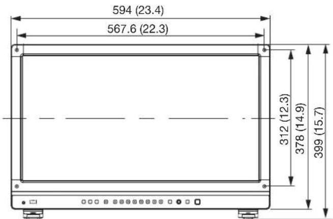
- Rear
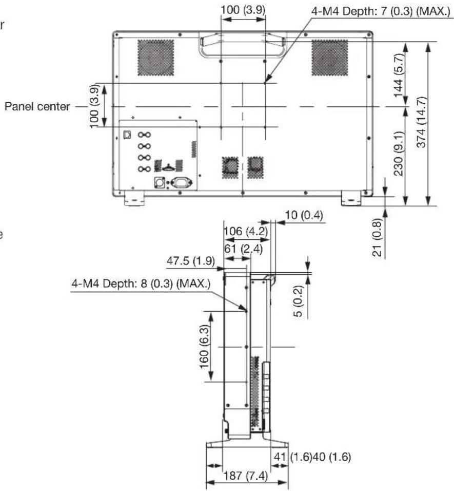
- Side
- Bottom
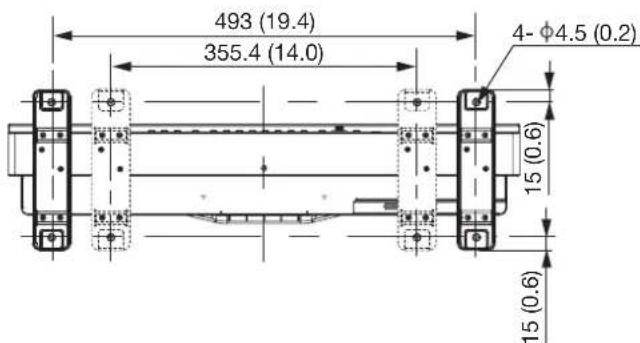
Unit: mm (inch)
Supported Signal Format
SDI
Formats with "*" support audio signals.
| Transmission method | Signal format Color format Color depth | Standards | ||
| SD-SDI 720x487i 59. | 94/60 Hz 4:2:2 YCbCr 10-bit SMPTE-259M | |||
| 720x576i 50.00 Hz | ||||
| HD-SDI 1280x720P 5 | 9.94/60.00 Hz* 4:2:2 YCbCr 10-bit SMPTE 292-1 | SMPTE 296 | ||
| 1280x720P 50.00 Hz* | ||||
| 1280x720P 29.97/30.00 Hz | ||||
| 1280x720P 25.00 Hz* | ||||
| 1280x720P 23.98/24.00 Hz* | ||||
| 1920x1080i 59.94/60.00 Hz* SMPTE 292-1 | SMPTE 274M | |||
| 1920x1080i 50.00 Hz* | ||||
| 1920x1080P 29.97/30.00 Hz* | ||||
| 1920x1080PsF 29.97/30.00 Hz* | ||||
| 1920x1080P 25.00 Hz* | ||||
| 1920x1080PsF 25.00 Hz* | ||||
| 1920x1080P 23.98/24.00 Hz* | ||||
| 1920x1080PsF 23.98/24.00 Hz* | ||||
| 2048x1080i 59.94/60.00 Hz | ||||
| 2048x1080i 50.00 Hz | ||||
| 2048x1080P 29.97/30.00 Hz SMPTE 292-1 | SMPTE 428-9 SMPTE 428-19 SMPTE 2048-2 | |||
| 2048x1080PsF 29.97/30.00 Hz | ||||
| 2048x1080P 25.00 Hz | ||||
| 2048x1080PsF 25.00 Hz | ||||
| 2048x1080P 23.98/24.00 Hz | ||||
| 2048x1080PsF 23.98/24.00 Hz | ||||
| 3G-SDI (Level A) | 1280x720P 59.94/60.00 Hz* 4:4:4 RGB 4:4:4 YCbCr | 10-bit SMPTE 425-1 SMPTE 296 | ||
| 1280x720P 50.00 Hz* 4:4:4 RGB 4:4:4 YCbCr | 10-bit | |||
| 1280x720P 29.97/30.00 Hz | 10-bit | |||
| 1280x720P 25.00 Hz* 4:4:4 RGB 4:4:4 YCbCr | 10-bit | |||
| 1280x720P 23.98/24.00 Hz* 4:4:4 RGB 4:4:4 YCbCr | 10-bit | |||
| 1920x1080P 59.94/60.00 Hz* | 4:2:2 YCbCr 10-bit SMPTE 425-1 | SMPTE 274M | ||
| 3G-SDI(Level A) | 1920x1080i 59.94/60.00 Hz 4:4:4 RGB*4:4:4 YCbCr* | 12-bit/10-bit SMPTE 425-1 | ||
| 4:2:2 YCbCr 12-bit | ||||
| 1920x1080P 50.00 Hz* 4:2:2 YCbCr | 10-bit | |||
| 1920x1080i 50.00 Hz 4:4:4 RGB* | 4:4:4 YCbCr* | 12-bit/10-bit | ||
| 4:2:2 YCbCr 12-bit | ||||
| 1920x1080P 29.97/30.00 Hz 4:4:4 RGB | 4:4:4 YCbCr | 12-bit/10-bit | ||
| 4:2:2 YCbCr 12-bit | ||||
| 1920x1080PsF 29.97/30.00 Hz 4:4:4 RGB* 10-bit | ||||
| 12-bit | ||||
| 4:4:4 YCbCr* 12-bit | ||||
| 4:4:4 YCbCr* 10-bit SMPTE 425-1 | SMPTE 274M | |||
| 4:2:2 YCbCr 12-bit | ||||
| 1920x1080P 25.00 Hz | 4:4:4 RGB4:4:4 YCbCr | 12-bit/10-bit | ||
| 4:2:2 YCbCr 12-bit | ||||
| 1920x1080PsF 25.00 Hz | 4:4:4 RGB* 10-bit | |||
| 12-bit | ||||
| 4:4:4 YCbCr* 12-bit | ||||
| 4:4:4 YCbCr* 10-bit SMPTE 425-1 | SMPTE 274M | |||
| 4:2:2 YCbCr 12-bit | ||||
| 1920x108O P 23.98/24.00 Hz 4:4:4 RGB*4:4:4 YCbCr* | 12-bit/10-bit | |||
| 4:2:2 YCbCr 12-bit | ||||
| 1920x1080PsF 23.98/24.00 Hz 4:4:4 RGB 10-bit | ||||
| 4:4:4 YCbCr 12-bit | ||||
| 4:4:4 YCbCr 10-bit SMPTE 425-1 | SMPTE 274M | |||
| 4:2:2 YCbCr 12-bit | ||||
| 2048x1080P 59.94/60.00 Hz 4:2:2 YCbCr 10-bit SMPTE 425-1 | SMPTE 428-9SMPTE 428-19SMPTE 2048-2 | |||
| 2048x1080i 59.94/60.00 Hz 4:4:4 RGB4:4:4 YCbCr | 12-bit/10-bit | |||
| 4:4:4 X'Y'Z' 12-bit | ||||
| 4:2:2 YCbCr | ||||
| 2048x1080P 50.00 Hz | 4:2:2 YCbCr 10-bit SMPTE 425-1 | SMPTE 2048-2 | ||
| 3G-SDI(Level A) | 2048x1080i 50.00 Hz 4:4:4 RGB | 4:4:4 YCbCr | 12-bit/10-bit | |
| 4:4:4 X'Y'Z' 12-bit | ||||
| 4:2:2 YCbCr | ||||
| 2048x1080P 47.95/48.00 Hz 4:2:2 YCbCr 10-bit SMPTE 425-1 | SMPTE 2048-2 | |||
| 2048x1080P 29.97/30.00 Hz 4:4:4 RGB 12-bit/10-bit SMPTE 425-1 | SMPTE 428-9SMPTE 428-19SMPTE 2048-2 | |||
| 3G-SDI(Level B) | 1920x1080P 59.94/60.00 Hz 4:2:2 | YCbCr 10-bit SMPTE 425-1 | SMPTE 372SMPTE 274M | |
| 1920x1080i 59.94/60.00 Hz 4:4:4 R | GB4:4:4 YCbCr | 12-bit/10-bit | ||
| 4:2:2 YCbCr* 12-bit | ||||
| 1920x1080P 50.00 Hz 4:2:2 YCbCr | 10-bit | |||
| 1920x1080i 50.00 Hz 4:4:4 RGB | 4:4:4 YCbCr | 12-bit/10-bit | ||
| 4:2:2 YCbCr* 12-bit | ||||
| 1920x1080P 29.97/30.00 Hz 4:4:4 R | RGB4:4:4 YCbCr | 12-bit/10-bit | ||
| 4:2:2 YCbCr 12-bit | ||||
| 1920x1080PsF 29.97/30.00 Hz 4:4:4 | RGB4:4:4 YCbCr | 12-bit/10-bit | ||
| 4:2:2 YCbCr 12-bit | ||||
| 1920x1080P 25.00 Hz 4:4:4 RGB | 4:4:4 YCbCr | 12-bit/10-bit | ||
| 4:2:2 YCbCr 12-bit | ||||
| 1920x1080PsF 25.00 Hz 4:4:4 RGB | 4:4:4 YCbCr | 12-bit/10-bit | ||
| 4:2:2 YCbCr 12-bit | ||||
| 1920x1080P 23.98/24.00 Hz 4:4:4 R | GB4:4:4 YCbCr | 12-bit/10-bit | ||
| 4:2:2 YCbCr 12-bit | ||||
| 1920x1080PsF 23.98/24.00 Hz 4:4:4 | RGB4:4:4 YCbCr | 12-bit/10-bit | ||
| 4:2:2 YCbCr 12-bit | ||||
| 2048x1080P 59.94/60.00 Hz 4:2:2 Y | CbCr 10-bit SMPTE 425-1 | SMPTE 372SMPTE 428-9SMPTE 428-19SMPTE 2048-2 | ||
| 2048x1080i 59.94/60.00 Hz 4:4:4 R | GB4:4:4 YCbCr | 12-bit/10-bit | ||
| 4:4:4 X'Y'Z'4:2:2 YCbCr | 12-bit | |||
| 2048x1080P 50.00 Hz 4:2:2 YCbCr | 10-bit SMPTE 425-1 | SMPTE 372SMPTE 2048-2 | ||
| 2048x1080i 50.00 Hz 4:4:4 RGB | 4:4:4 YCbCr | 12-bit/10-bit | ||
| 4:4:4 X'Y'Z'4:2:2 YCbCr | 12-bit | |||
| 3G-SDI(Level B) | 2048x1080P 47.95/48.00 Hz 4:2:2 Y | CbCr 10-bit SMPTE 425-1 | SMPTE 372SMPTE 2048-2 | |
| 2048x1080P 29.97/30.00 Hz 4:4:4 R | GB 12-bit/10-bit SMPTE 425-1 | SMPTE 372SMPTE 428-9SMPTE 428-19SMPTE 2048-2 | ||
| 4:4:4 X'Y'Z' 12-bit | ||||
| 4:4:4 YCbCr 12-bit/10-bit SMPTE 425-1 | SMPTE 372SMPTE 2048-2 | |||
| 4:2:2 YCbCr 12-bit | ||||
| 2048x1080PsF 29.97/30.00 Hz 4:4:4 | RGB 12-bit/10-bit SMPTE 425-1 | SMPTE 372SMPTE 428-9SMPTE 428-19SMPTE 2048-2 | ||
| 4:4:4 X'Y'Z' 12-bit | ||||
| 4:4:4 YCbCr 12-bit/10-bit SMPTE425-1 | SMPTE 372SMPTE 2048-2 | |||
| 4:2:2 YCbCr 12-bit | ||||
| 2048x1080P 25.00 Hz 4:4:4 RGB | 12-bit/10-bit SMPTE 425-1 | SMPTE 372SMPTE 428-9SMPTE 428-19SMPTE 2048-2 | ||
| 4:4:4 X'Y'Z' 12-bit | ||||
| 4:4:4 YCbCr 12-bit/10-bit SMPTE 12-bit SMPTE 425-1 | SMPTE 372SMPTE 2048-2 | |||
| 4:2:2 YCbCr 12-bit | ||||
| 2048x1080PsF 25.00 Hz 4:4:4 RGB | 12-bit/10-bit SMPTE 425-1 | SMPTE 372SMPTE 428-9SMPTE 428-19SMPTE 2048-2 | ||
| 4:4:4 X'Y'Z' 12-bit | ||||
| 4:4:1 YCbCr 12-bit/10-bit SMPTE 425-1 | SMPTE 372SMPTE 2048-2 | |||
| 4:2:2 YCbCr 12-bit | ||||
| 2048x1080P 23.98/24.00 Hz 4:4:4 | RGB 12-bit/10-bit SMPTE 425-1 | SMPTE 372SMPTE 428-9SMPTE 428-19SMPTE 2048-2 | ||
| 4:4:4 X'Y'Z' 12-bit | ||||
| 4:4:4 YCBCr 12-bit/10-bit SMPTE 425-1 | SMPTE 372SMPTE 2048-2 | |||
| 4:2:2 YCBCr 12-bit | ||||
| 3G-SDI(Level B) | 2048x1080PsF 23.98/24.00 Hz 4:4:4 | RGB 12-bit/10-bit SMPTE 425-1 | SMPTE 372SMPTE 428-9SMPTE 428-19SMPTE 2048-2 | |
| 4:4:4 X'Y'Z' 12-bit | ||||
| 4:4:4 YCbCr 12-bit/10-bit SMPTE 425-1 | SMPTE 372SMPTE 2048-2 | |||
| 4:2:2 YCbCr 12-bit | ||||
| Dual Link 3G-SDI(Level A) | 1920x1080P 59.94/60 Hz 4:4:4 RGB | 4:4:4 YCbCr | 12-bit/10-bit SMPTE 425-3SMPTE 274M | |
| 4:2:2 YCbCr 12-bit | ||||
| 1920x1080P 50 Hz 4:4:4 RGB | 4:4:4 YCbCr | 12-bit/10-bit | ||
| 4:2:2 YCbCr 12-bit | ||||
| 2048x1080P 59.94/60 Hz 4:4:4 RGB | 4:4:4 YCbCr | 12-bit/10-bit SMPTE 425-3SMPTE 428-9SMPTE 428-19SMPTE 2048-2 | ||
| 4:4:4 X'Y'Z'4:2:2 YCbCr | 12-bit | |||
| 2048x1080P 50 Hz 4:4:4 RGB | 4:4:4 YCbCr | 12-bit/10-bit | ||
| 4:4:4 X'Y'Z'4:2:2 YCbCr | 12-bit | |||
| 2048x1080P 47.95/48 Hz 4:4:4 RGB | 4:4:4 YCbCr | 12-bit/10-bit | ||
| 4:4:4 X'Y'Z'4:2:2 YCbCr | 12-bit | |||
| Dual Link 3G-SDI(Level B) | 1920x1080P 59.94/60 Hz 4:4:4 RGB | 4:4:4 YCbCr | 12-bit/10-bit SMPTE 425-3SMPTE 372SMPTE 274M | |
| 4:2:2 YCbCr 12-bit | ||||
| 1920x1080P 50 Hz 4:4:4 RGB | 4:4:4 YCbCr | 12-bit/10-bit | ||
| 4:2:2 YCbCr 12-bit | ||||
| 2048x 1080P 59.94/60 Hz 4:4:4 RGB | 4:4:4 YCbCr | 12-bit/10-bit SMPTE 425-3SMPTE 372SMPTE 428-9SMPTE 428-19SMPTE 2048-2 | ||
| 4:4:4 X'Y'Z'4:2:2 YCbCr | 12-bit | |||
| 2048x1080P 50 Hz 4:4:4 RGB | 4:4:4 YCbCr | 12-bit/1O-bit | ||
| 4:4:4 X'Y'Z'4:2:2 YCbCr | 12-bit | |||
| 2048x1080P 47.95/48 Hz 4:4:4 RGB | 4:4:4 YCbCr | 12-bit/10-bit | ||
| 4:4:4 X'Y'Z'4:2;2 YCbCr | 12-bit | |||
| Dual Link 3G-SDI Square Division (Level B) | 3840x2160P 29.97/30 Hz 4:2:2 YCbCr 10-bit SMPTE 425-3 | SMPTE 372 SMPTE 274M | ||
| 3840x2160PsF 29.97/30 Hz | ||||
| 3840x2160P 25 Hz | ||||
| 3840x2160PsF 25 Hz | ||||
| 3840x2160P 23.98/24 Hz | ||||
| 3840x2160PsF 23.98/24 Hz | ||||
| 4096x2160P 29.97/30 Hz SMPTE 425-3 | SMPTE 372 SMPTE 2048-2 | |||
| 4096x2160PsF 29.97/30 Hz | ||||
| 4096x2160P 25 Hz | ||||
| 4096x2160PsF 25 Hz | ||||
| 4096x2160P 23.98/24 Hz | ||||
| 4096x2160PsF 23.98/24 Hz | ||||
| Dual Link 3G-SDI 2 Sample Interleave (Level B) | 3840x2160P 29.97/30 Hz 4:2:2 YCbCr 10-bit SMPTE 425-3 | SMPTE 372 SMPTE 274M | ||
| 3840x2160P 25 Hz | ||||
| 3840x2160P 23.98/24 Hz | ||||
| 4096x2160P 29.97/30 Hz SMPTE 425-3 | SMPTE 372 SMPTE 2048-2 | |||
| 4096x2160P 25 Hz | ||||
| 4096x2160P 23.98/24 Hz | ||||
| Quad Link HD-SDI 38 | 40x2160i 59.94/60.00 Hz* 4:2:2 YCbCr 10-bit SMPTE 292-1 | SMPTE 274M | ||
| 3840x2160i 50.00 Hz* | ||||
| 3840x2160P 29.97/30.00 Hz* | ||||
| 3840x2160PsF 29.97/30.00 Hz* | ||||
| 3840x2160P 25.00 Hz* | ||||
| 3840x2160PsF 25.00 Hz* | ||||
| 3840x2160P 23.98/24.00 Hz* | ||||
| 3840x2160PsF 23.98/24.00 Hz* | ||||
| 4096x2160i 59.94/60.00 Hz | ||||
| 4096x2160i 50.00 Hz | ||||
| 4096x2160P 29.97/30.00 Hz SMPTE 292-1 | SMPTE 428-9 SMPTE 428-19 SMPTE 2048-2 | |||
| 4096x2160PsF 29.97/30.00 Hz | ||||
| 4096x2160P 25.00 Hz | ||||
| 4096x2160PsF 25.00 Hz | ||||
| 4096x2160P 23.98/24.00 Hz | ||||
| 4096x2160PsF 23.98/24.00 Hz | ||||
| Quad Link 3G-SDI(Level A) | 3840x2160P 59.94/60.00 Hz 4:2:2 | YCbCr^* 10-bit SMPTE 425-1 | SMPTE 274M | |
| 3840x2160i 59.94/60.00 Hz 4:4:4 R | GB^* 4:4:4 YCbCr^* | 12-bit/10-bit | ||
| 4:2:2 YCbCr 12-bit | ||||
| 3840x2160P 50.00 Hz 4:2:2 YCbCr^* | 12-bit | |||
| 3840x2160i 50.00 Hz 4:4:4 RGB^* | 4:4:4 YCbCr^* | 12-bit/10-bit | ||
| 4:2:2 YCbCr 12-bit | ||||
| 3840x2160P 29.97/30.00 Hz 4:4:4 R | RGB4:4:4 YCbCr | 12-bit/10-bit | ||
| 4:2:2 YCbCr 12-bit | ||||
| 3840x2160PsF 29.97/30.00 Hz 4:4:4 | RGB^* 10-bit | |||
| 12-bit | ||||
| 4:4:4 YCbCr^* 12-bit | ||||
| 4:4:4 YCbCr^* 10-bit SM | MPTE 425-1 | SMPTE 274M | ||
| 4:2:2 YCbCr 12-bit | ||||
| 3840x2160P 25.00 Hz 4:4:4 RGB | 4:4:4 YCbCr | 12-bit/10-bit | ||
| 4:2:2 YCbCr 12-bit | ||||
| 3840x2160PsF 25.00 Hz 4:4:4 RGB^* | 10-bit | |||
| 12-bit | ||||
| 4:4:4 YCbCr^* 12-bit | ||||
| 4:4:4 YCbCr^* 10-bit SM | MPTE 425-1 | SMPTE 274M | ||
| 4:2:2 YCbCr 12bit | ||||
| 3840x2160P 23.98/24.00 Hz 4:4:4 R | GB^* 4:4:4 YCbCr^* | 12-bit/10-bit | ||
| 4:2:2 YCbCr 12-bit | ||||
| 3840x2160PsF 23.98/24.00 Hz 4:4:4 | RGB 10-bit | |||
| 12-bit | ||||
| 4:4:4 YCbCr 12-bit | ||||
| 4:4:4 YCbCr 10-bit SM | MPTE 425-1 | SMPTE 274M | ||
| 4:2:2 YCbCr 12-bit | ||||
| 4096x2160P 59.94/60.00 Hz 4:2:2 Y | CbCr 10-bit SMPTE 425-1 | SMPTE 428-9SMPTE 428-19SMPTE 2048-2 | ||
| 4096x2160i 59.94/60.00 Hz 4:4:4 R | GB4:4:4 YCbCr | 12-bit/10-bit | ||
| 4:4:4 X'Y'Z' 4:2:2 YCbCr | 12-bit | |||
| Quad Link 3G-SDI (Level A) | 4096x2160P 50.00 Hz 4:2:2 YCbCr | 10-bit SMPTE 425-1 | SMPTE 2048-2 | |
| 4096x2160i 50.00 Hz 4:4:4 RGB | 4:4:4 YCbCr | 12-bit/10-bit | ||
| 4:4:4 X'Y'Z'4:2:2 YCbCr | 12-bit | |||
| 4096x2160P 47.95/48.00 Hz 4:2:2 YCbCr 10-bit SMPTE 425-1 | SMPTE 2048-2 | |||
| 4096x2160P 29.97/30.00 Hz 4:4:4 RGB 12-bit/10-bit SMPTE 425-1 | SMPTE 428-9SMPTE 428-19SMPTE 2048-2 | |||
| Quad Link 3G-SDI2 Sample Interleave(Level A) | 3840x2160P 59.94/60 Hz 4:2:2 YCb | Cr 10-bit SMPTE 425-5 | SMPTE 274M | |
| 3840x2160P 50 Hz 4:2:2 YCbCr 10 | bit | |||
| 3840x2160P 29.97/30 Hz 4:4:4 RGB | 4:4:4 YCbCr | 12-bit/10-bit | ||
| 4:2:2 YCbCr 12-bit | ||||
| 3840x2160P 25 Hz 4:4:4 RGB | 4:4:4 YCbCr | 12-bit/10-bit | ||
| 4:2:2 YCbCr 12-bit | ||||
| 3840x2160P 23.98/24 Hz 4:4:4 RGB | 4:4:4 YCbCr | 12-bit/10-bit | ||
| 4:2:2 YCbCr 12-bit | ||||
| 4096x2160P 59.94/60 Hz 4:2:2 YCb | Cr 10-bit SMPTE 425-5 | SMPTE 428-9SMPTE 428-19SMPTE 2048-2 | ||
| 4096x2160P 50 Hz 4:2:2 YCbCr 10 | -bit | |||
| 4096x2160P 47.95/48 Hz 4:2:2 YCb | Cr 10-bit | |||
| 4096x2160P 29.97/30 Hz 4:4:4 RGB | 12-bit/10-bit | |||
| 4:4:4 X'Y'Z' 12-bit | ||||
| 4:4:4 YCbCr 12-bit/10-bit | ||||
| 4:2:2 YCbCr 12-bit | ||||
| 4096x2160P 25 Hz 4:4:4 RGB 12-bit/10-bit | ||||
| 4096x2160P 23.98/24 Hz 4:4:4 RGB | 12-bit/10-bit | |||
| SMPTE 372SMPTE 274M | ||||
| 3840x2160P 59.94/60.00 Hz 4:2:2 YCbCr 10-bit SMPTE 425-1 | ||||
| 3840x2160i 59.94/60.00 Hz 4:4:4 RGB 4:4:4 YCbCr | GB 12-bit/10-bit | |||
| 4:2:2 YCbCr* 12-bit | ||||
| 4:2:2 YCbCr 10-bit | ||||
| 3840x2160P 50.00 Hz | 4:2:2 YCbCr 10-bit | |||
| Quad Link 3G-SDI (Level B) | 3840x2160i 50.00 Hz 4:4:4 RGB | 4:4:4 YCbCr | 12-bit/10-bit SMPTE 425-1 SMPTE 372 SMPTE 274M | |
| 4:2:2 YCbCr* 12-bit | ||||
| 3840x2160P 29.97/30.00 Hz 4:4:4 RGB | 4:4:4 YCbCr | 12-bit/10-bit | ||
| 4:2:2 YCbCr 12-bit | ||||
| 3840x2160PsF 29.97/30.00 Hz 4:4:4 RGB | 4:4:4 YCbCr | 12-bit/10-bit | ||
| 4:2:2 YCbCr 12-bit | ||||
| 3840x2160P 25.00 Hz 4:4:4 RGB | 4:4:4 YCbCr | 12-bit/10-bit | ||
| 4:2:2 YCbCr 12-bit | ||||
| 3840x2160PsF 25.00 Hz 4:4:4 RGB | 4:4:4 YCbCr | 12-bit/10-bit | ||
| 4:2:2 YCbCr 12-bit | ||||
| 3840x2160P 23.98/24.00 Hz 4:4:4 RGB | 4:4:4 YCbCr | 12-bit/10-bit | ||
| 4:2:2 YCbCr 12-bit | ||||
| 3840x2160PsF 23.98/24.00 Hz 4:4:4 RGB | 4:4:4 YCbCr | 12-bit/10-bit | ||
| 4:2:2 YCbCr 12-bit | ||||
| 4096x2160P 59.94/60.00 Hz 4:2:2 YCbCr 10-bit SMPTE 425-1 | SMPTE 372 SMPTE 428-9 SMPTE 428-19 SMPTE 2048-2 | |||
| 4096x2160i 59.94/60.00 Hz 4:4:4 RGB | 4:4:4 YCbCr | 12-bit/10-bit | ||
| 4:4:4 X'Y'Z' 4:2:2 YCbCr | 12-bit | |||
| 4096x2160P 50.00 Hz 4:2:2 YCbCr | 10-bit SMPTE 425-1 | SMPTE 372 SMPTE 2048-2 | ||
| 4096x2160i 50.00 Hz 4:4:4 RGB | 4:4:4 YCbCr | 12-bit/10-bit | ||
| 4:4:4 X'Y'Z' 4:2:2 YCbCr | 12-bit | |||
| 4096x2160P 47.95/48.00 Hz 4:2:2 YCbCr 10-bit SMPTE 425-1 | SMPTE 372 SMPTE 2048-2 | |||
| Quad Link 3G-SDI (Level B) | 4096x2160P 29.97/30.00 Hz 4:4:4 RGB 12-bit/10-bit SMPTE 425-1 | SMPTE 372SMPTE 428-9SMPTE 428-19SMPTE 2048-2 | ||
| Quad Link 3G-SDI2 Sample Interleave(Level B) | 3840x2160P 59.94/60 Hz 4:2:2 YCbCr 10-bit SMPTE 425-5 | SMPTE 372SMPTE 274M | ||
| 3840x2160P 50 Hz 4:2:2 YCbCr 10-bit | ||||
| 3840x2160P 29.97/30 Hz 4:4:4 RGB | 4:4:4 YCbCr | 12-bit/10-bit | ||
| 4:2:2 YCbCr 12-bit | ||||
| 3840x2160P 25 Hz 4:4:4 RGB | 4:4:4 YCbCr | 12-bit/10-bit | ||
| 4:2:2 YCbCr 12-bit | ||||
| 3840x2160P 23.98/24 Hz 4:4:4 RGB | 4:4:4 YCbCr | 12-bit/10-bit | ||
| 4:2:2 YCbCr 12-bit | ||||
| 4096x2160P 59.94/60 Hz 4:2:2 YCbCr 10-bit SMPTE 425-5 | SMPTE 372SMPTE 428-9SMPTE 428-19SMPTE 2048-2 | |||
| 4096x2160P 50 Hz 4:2:2 YCbCr 10-bit | ||||
| 4096x2160P 47.95/48 Hz 4:2:2 YCbCr 10-bit | ||||
| 4096x2160P 29.97/30 Hz 4:4:4 RGB | 12-bit/10-bit | |||
| 4:4:4 X'Y'Z' 12-bit | ||||
| 4:4:4 YCbCr 12-bit/10-bit | ||||
| 4:2:2 YCbCr 12-bit | ||||
| 4096x2160P 25 Hz 4:4:4 RGB 12-bit/10-bit | ||||
| 4:4:4 X'Y'Z' 12-bit | ||||
| 4:4:4 YCbCr 12-bit/10-bit | ||||
| 4:2:2 YCbCr 12-bit | ||||
| 4096x2160P 23.98/24 Hz 4:4:4 RGB | 12-bit/10-bit | |||
| 4:4:4 X'Y'Z' 12-bit | ||||
| 4:4:4 YCbCr 12-bit/10-bit | ||||
| 4:2:2 YCbCr 12-bit | ||||
| Signal format |
| 3840x2160P 59.94 Hz, 50.00 Hz, 29.97 Hz, 25.00 Hz, 24.00 Hz, 23.98 Hz |
| 4096x2160P 59.94 Hz, 50.00 Hz, 29.97 Hz, 25.00 Hz, 24.00 Hz, 23.98 Hz |
HDMI
| Signal format Color format/Color depth | ||||
| 640x480P 59.94/60.00 Hz 4:4:4 RGB 8-bit | ||||
| 800x600P 60.00 Hz | ||||
| 1024x768P 60.00 Hz | ||||
| 720x480P 59.94/60.00 Hz 4:4:4 RGB 12-bit/10-bit/8-bit | ||||
| 720x576P 50.00 Hz | 4:4:4 YCbCr 12-bit/10-bit/8-bit | |||
| 1280x720P 59.94/60.00 Hz | 4:2:2 YCbCr 12-bit | |||
| 1280x720P 50.00 Hz | ||||
| 1920x1080P 59.94/60.00 Hz | ||||
| 1920x1080i 59.94/60.00 Hz | ||||
| 1920x1080P 50.00 Hz | ||||
| 1920x1080i 50.00 Hz | ||||
| 1920x1080P 29.97/30.00 Hz | ||||
| 1920x1080P 25.00 Hz | ||||
| 1920x1080P 23.98/24.00 Hz | ||||
| 2048x1080P 59.94/60.00 Hz | ||||
| 2048x1080P 50.00 Hz | ||||
| 2048x1080P 29.97/30.00 Hz | ||||
| 2048x1080P 25.00 Hz | ||||
| 2048x1080P 23.98/24.00 Hz | ||||
| 3840x2160P 59.94/60.00 Hz 4:4:4 RGB | 8-bit | |||
| 3840x2160P 50.00 Hz | 4:4:4 YCbCr 8-bit | |||
| 4:2:2 YCbCr 12-bit | ||||
| 4:2:0 YCbCr 12-bit/10-bit/8-bit | ||||
| 3840x2160P 29.97/30.00 Hz 4:4:4 RGB | 12-bit/10-bit/8-bit | |||
| 3840x2160P 25.00 Hz | 4:4:4 YCbCr 12-bit/10-bit/8-bit | |||
| 3840x2160P 23.98/24.00 Hz | 4:2:2 YCbCr 12-bit | |||
| 4096x2160P 59.94/60.00 Hz 4:4:4 RGB | 8-bit | |||
| 4096x2160P 50.00 Hz | 4:4:4 YCbCr 8-bit | |||
| 4:2:2 YCbCr 12-bit | ||||
| 4:2:0 YCbCr 12-bit/10-bit/8-bit | ||||
| 4096x2160P 29.97/30.00 Hz 4:4:4 RGB | 12-bit/10-bit/8-bit | |||
| 4096x2160P 25.00 Hz | 4:4:4 YCbCr 12-bit/10-bit/8-bit | |||
| 4096x2160P 23.98/24.00 Hz | 4:2:2 YCbCr 12-bit | |||
| Signal system Display Method | ||||
| 720x487 59.94/60.00 | i 59.94/60.00 P | |||
| 720x576 50.00 i 50.00 | P | |||
| 1280x720 23.98/24.00 | P47.96/48.00 P* | |||
| 25.00 P50.00 P* | ||||
| 29.97/30.00 P59.94/60.00 P* | ||||
| 50.00 P50.00 P | ||||
| 59.94/60.00 P59.94/60.00 P | ||||
| 1920x1080 50.00 i 50.00 | P | |||
| 59.94/60.00 i 59.94/60.00 P | ||||
| 23.98/24.00 PsF 47.96/48.00 P* | ||||
| 25.00 PsF 50.00 P* | ||||
| 29.97/30.00 PsF 59.94/60.00 P* | ||||
| 23.98/24.00 P47.96/48.00 P* | ||||
| 25.00 P50.00 P* | ||||
| 29.97/30.00 P59.94/60.00 P* | ||||
| 50.00 P50.00 P | ||||
| 59.94/60,00 P59.94/60.00 P | ||||
| 2048x1080 50.00 i 50.00 | P | |||
| 59.94/60.00 i 59.94/60.00 P | ||||
| 23.98/24.00 PsF 47.96/48.00 P* | ||||
| 25.00 PsE 50.00 P* | ||||
| 29.97/30.00 PsF 59.94/60.00 P* | ||||
| 23.98/24.00 P47.96/48.00 P* | ||||
| 25.00 P50.00 P* | ||||
| 29.97/30.00 P59.94/60.00 P* | ||||
| 47.95/48.00 P47.95/48.00 P | ||||
| 50.00 P50.00 P | ||||
| 59.94/60.00 P59.94/60.00 P | ||||
| 3840x2160 50.00 i 50.00 | P | |||
| 59.94/60.00 i 59.94/60.00 P | ||||
| 23.98/24.00 PsF 47.96/48.00 P* | ||||
| 25.00 PsF 50,00 P* | ||||
| 29.97/30.00 PsF 59.94/60.00 P* | ||||
| 23.98/24.00 P47.96/48.00 P* | ||||
| 25.00 P50.00 P* | ||||
| 29,97/30.00 P59.94/60.00 P* | ||||
| 50.00 P50.00 P | ||||
| 59.94/60.00 P59.94/60.00 P | ||||
| 4096x2160 50.00 i 50.00 P | ||||
| 59.94/60.00 i 59.94/60.00 P | ||||
| 23.98/24.00 PsF 47.96/48.00 P* | ||||
| 25.00 PsF 50.00 P* | ||||
| 29.97/30.00 PsF 59.94/60.00 P* | ||||
| 23.98/24.00 P47.96/48.00 P* | ||||
| 25.00 P50.00 P* | ||||
| 29.97/30.00 P59.94/60.00 P* | ||||
| 47.95/48.00 P47.95/48.00 P | ||||
| 50.00 P50.00 P | ||||
| 59.94/60.00 P59.94/60.00 P | ||||
* : Displaying same frame
| Signal system Display Method | ||||
| 640x480 59.94/60.00 | P59.94/60.00 P | |||
| 800x600 60.00 P60.00 | P | |||
| 720x480P 59.94/60.00 | P59.94/60.00 P | |||
| 720x576 50.00 P50.00 | P | |||
| 1024x768 60.00 P60.00 | P | |||
| 1280x720 59.94/60.00 | P59.94/60.00 P | |||
| 1280x720 50.00 P50.00 | P | |||
| 1920x1080 59.94/60.00 | P59.94/60.00 P | |||
| 1920x1080 59.94/60.00 | i 59.94/60.00 P | |||
| 1920x1080 50.00 P50.00 | P | |||
| 1920x1080 50.00 i 50.00 | P | |||
| 1920x1080 59.94/60.00 | i 59.94/60.00 P | |||
| 1920x1080 29.97/30.00 | P59.94/60.00 P* | |||
| 1920x1080 25.00 P50.00 | P* | |||
| 1920x1080 23.98/24.00 | P47.96/48.00 P* | |||
| 2048x1080 59.94/60.00 | P59.94/60.00 P | |||
| 2048x1080 50.00 P50.00 | P | |||
| 2048x1080 29.97/30.00 | P59.94/60.00 P* | |||
| 2048x1080 25.00 P50.00 | P* | |||
| 2048x1080 23.98/24.00 | P47.96/48.00 P* | |||
| 3840x2160 59.94/60.00 | P59.94/60.00 P | |||
| 3840x2160 50.00 P50.00 | P | |||
| 3840x2160 29.97/30.00 | P59.94/60.00 P* | |||
| 3840x2160 25.00 P50.00 | P* | |||
| 3840x2160 23.98/24.00 | P47.96/48.00 P* | |||
| 4096x2160 59.94/60.00 | P59.94/60.00 P | |||
| 4096x2160 50.00 P50.00 | P | |||
| 4096x2160 29.97/30.00 | P59.94/60.00 P* | |||
| 4096x2160 25.00 P50.00 | P* | |||
| 4096x2160 23.98/24.00 | P47.96/48.00 P* | |||
* : Displaying same frame
| Message Description and Action | ||
| Calibration Failed to initialize the external sensor. See CA-310 and CA-210 instruction manual. | ||
| Network Communication error. IP address may be in conflict or there may be a network communication error. Check the network environment. | ||
| Various settings, CDL export | The USB memory is full. Use another USB memory or delete the content of the memory. | |
| Failed to write file. The USB memory may be defective or protected. Check the USB memory. | ||
| LUT, Various settings, CDL import | (LUT Import) "LUT Type" is different. (CDL Import) "File Type" is different. | Select the correct file format. |
| Failed to read file. | The USB memory may be defective or protected. Check the USB memory. | |
| Failed to import. | There is an error in the file to be imported. Check the file. | |
| No import file. | Check and ensure that the file has been saved to the USB memory or imported to "User 1-3". | |
| Message Description and Action | |||
| Screen Capture | Failed to capture. The USB memory may be defective or protected.Check the USB memory. | ||
| Invalid Signal. A screen displaying no video is being captured forexample there is no signal or an unsupported signal is being input. Check the signal, input it again, and capture it. | |||
| Copy protected signal. The signal you tried to capture may be protected by HDCP 2.2 which is a copy prevention standard for HDMI. In this case, the signal cannot be captured. Check the HDMI signal. | |||
| Failed to playback file. The USB memory or the file may be defective or protected. Check the USB memory or the file. | |||
| No capture file. Check and ensure that the file has been saved to the USB memory. | |||
| Hardware error Back | ight error. Disconnect the power cord, reconnect it, and then turn on the power. | ||
| Fan error. | |||
| Panel error. | |||
| I/F error. | |||
| System error. | |||
| Invalid operation due to high temperature. The temperature inside the main unit is high. Turn off the power and wait until the fan stops. | |||
| Input signal No Signal | Displayed when there is no video signal input. | ||
| Unsupported Unsupported video signal is input. Check the supported signal format (105). | |||
| Operation | Invalid operation. | Operation is disabled. Check the setting items. | |
| "Protect Settings" is on. | To use the OSD menu, move the selection frame to "Protect" and press the jog dial for approximately 3 seconds. | ||
| "CDL/User LUT Bypass" is on. | When "CDL/User LUT Bypass" is turned "On", you cannot adjust "Power", "Saturation", "Offset", or "Slope". | ||
| Invalid Password. | Enter the correct password. | ||
| USB memory | USB memory is not connected. | Correctly connect the USB memory to the USB port of this main unit. | |
| Unsupported USB memory. | Check the USB memory format and make sure it is not protected. | ||
| Wi-Fi adapter | Wi-Fi Adaptor is not connected. | Correctly connect the Wi-Fi adapter to the USB terminal of the video display. | |
| Failed to connect Wi-Fi Access Point. | The password may be wrong, or there may be a network communication error. Check the network environment. | ||
| Firmware Update No | update file. Firmware update files are not saved on USB memory or other media. | ||
| Failed to read update file. There is an error in the file. Check the file. | |||
| The firmware/license has been already updated. This is the file that is updated on the video display. | |||
| DC power supply Low Voltage. Indicates that the input voltage of the DC power supply has become below approx. 22.5 V. Check the voltage of the DC power supply. | |||
| Symptom Cause and Action | |||
| Power does not turn on.(Power indicator does not turn on.) | Press the button.Check that the AC power supply or DC power cord is connected correctly.Brightness of the power indicator may be turned off. Turn it on and check once more. | 91796 | |
| The screen is dark. When the power indicator does not turn on:Press the button.Check that the AC power supply or DC power cord is connected correctly. | 917 | ||
| When the power indicator is lit orange:Press the button. | 9 | ||
| When the power indicator is flashing orange:Flashing once every 3 seconds : Contact Canon Customer Center.Flashing twice every 3 seconds :- Turn on the power with the button.- The temperature of the display rises (or falls) depend on operation environment. Check the environmental conditions (102) and do not use in direct sunlight.- If the power still does not turn on, contact Canon Customer Center. | 9102 | ||
| The power suddenly goes off when a DC power supply is used. | Some DC power supply units turn off the voltage when a threshold value is reached. In this case, the message indicating low voltage is not displayed. Connect a charged DC power supply or AC power supply. | - | |
| The image does not display. | Set each item in "Channel Settings" according to input signal. | 60 | |
| The 3G-SDI RAW signal image does not display. | At times the 3G-SDI RAW signal image may not display, depending on the type of the Cinema EOS camera. Refer to the Canon website for a list of supported products. | - | |
| There is a blank area when set to Quad Input/Dual Input. | There may be no input signal. Look at the display area icon in the interface area and check that the input area and signal cables are properly connected.Signals with different resolution or frequency may be input from each terminal. Check the signal. | 15101 | |
| Video paused temporarily • The screen | may pause when running "Capture" via a web browser.When "Capture" is complete, or turning "Web" → "Control" to "Off" will return to normal screen. | 35 | |
| Screen is too bright/dark. • Adjust the "Contrast" on the OSD menu.There is a limit on the service life of LCD backlight. If the screen becomes dark or starts flickering, contact Canon Customer Center. | 45 | ||
| Burn-in image appears. • This is a characteristic of the LCD panel and you should avoid displaying stationary image for a long time. | — | ||
| There is an unlit or red, blue, green, or white dot on screen. | • LCD display is made of very high precision technology. It has effective pixels of 99.99% or more, but there may be black dots or red, blue, or green dots that may be always on. This is not a failure. | — | |
| There is an interference pattern or trace that remains when the LCD panel is pressed. | • The symptom may be resolved by displaying a white or black image on the entire screen. — | ||
| OSD menu cannot be used. • Check that "Protect Settings" is not set. 96 | |||
| "Aspect Marker", "Safety Zone Marker" or "Area Marker" does not appear. | • A channel with no signal, unsupported signal, or with "Input Configuration" not set may be selected. Check the signal. | 101 | |
| The fan starts to rotate even when "Fan" under "Camera Link" is set to "On" "Fan Stop" is set to "On". | • The fan stays off for approx. 1 minute when an AC power supply is used. To keep the fan off for a longer period, use a DC power supply. When "Fan" under "Camera Link" is set to "On", the down time may not match the camera. | 8797 | |
| The fan does not stop even when "Fan" under "Camera Link" is set to "On" "Fan Stop" is set to "On". | • The fan does not stop if the internal temperature of the video display is high. Configure settings after the internal temperature has lowered. The fan may not stop in some conditions, for example when used at a high temperature. Use the video display at the operating temperature (102) or lower. | 8797 | |
| You forgot the password for "Protect Settings". | • Press the jog dial and the button while the video display is in standby. The configuration will be reset to the state where no password is set. | 9 | |
| The video display does not start up in the condition that the power was turned off last time. | • Check the "Power on Setting" on the OSD menu. Set "Last memory" to start up the video display in the condition that the power is turned off last time. | 98 | |
| The image quality for the User mode in "Picture Mode" differs from the image quality of presets. | • Select the preset mode by "Copy Picture Mode" and copy the settings. | 56 | |
| Image quality on the left and right screens is different. | • Check the "Channel Settings" > "Picture Mode" settings. | 2262 | |
| Image quality is automatically changed. | |||
| The same image is displayed in two screens. | • Check the "Channel Settings" > "Single Input Dual View" settings. | 63 | |
Software installed with this product includes software modules from Canon or third parties.
Software Developed by Canon and Free Software
Software developed or created by Canon and accompanying document is protected by copyright law, terms of an international convention and any other governing laws.
This product uses software modules under copyright by third parties and distributed as free software. Some of these software modules are subject to the GNU General Public License v2 (GPL), GNU Lesser General Public License v2.1 (LGPL) or any other license.
Free software modules installed with this product
- linux kernel
- busybox
- glibc
- JFFS2
- SquashFS
- FUSE
- libfuse
- libupnp
- avahi-autoipd
- libxml
- zlib
- libpng
- Newlib(libc) - Newlib(libm) - wireless_tools - wpa_supplicant
- openssl
- libnl
- RealTek_WiFi_linux driver
- dhcp
- hostapd
Acquiring Source Code for Free Software
Some free software requires the acquirement of the source code of modules in order to distribute the executable form of those software modules. For information on how to acquire the source code for free software such as these and confirming terms of the GPL, LGPL and other license agreements, please check with the distributor from whom the product was purchased.
License Agreement for this Product
Obligation to Present License Agreement
The copyright holders of software modules installed with this product require its license agreement to be displayed. This license agreement is as follows:
libupnp License
Copyright (c) 2000-2003 Intel Corporation All rights reserved.
Redistribution and use in source and binary forms, with or without modification, are permitted provided that the following conditions are met:
* Redistributions of source code must retain the above copyright notice, this list of conditions and the following disclaimer.
* Redistributions in binary form must reproduce the above copyright notice, this list of conditions and the following disclaimer in the documentation and/or other materials provided with the distribution.
* Neither name of Intel Corporation nor the names of its contributors may be used to endorse or promote products derived from this software without specific prior written permission.
THIS SOFTWARE IS PROVIDED BY THE COPYRIGHT HOLDERS AND CONTRIBUTORS "AS IS" AND ANY EXPRESS OR IMPLIED WARRANTIES, INCLUDING, BUT NOT LIMITED TO, THE IMPLIED WARRANTIES OF MERCHANTABILITY AND FITNESS FOR A PARTICULAR PURPOSE ARE DISCLAIMED. IN NO EVENT SHALL INTEL OR CONTRIBUTORS BE LIABLE FOR ANY DIRECT, INDIRECT, INCIDENTAL, SPECIAL, EXEMPLARY, OR CONSEQUENTIAL DAMAGES (INCLUDING, BUT NOT LIMITED TO, PROCUREMENT OF SUBSTITUTE GOODS OR SERVICES; LOSS OF USE, DATA, OR PROFITS; OR BUSINESS INTERRUPTION) HOWEVER CAUSED AND ON ANY THEORY OF LIABILITY, WHETHER IN CONTRACT, STRICT LIABILITY, OR TORT (INCLUDING NEGLIGENCE OR OTHERWISE) ARISING IN ANY WAY OUT OF THE USE OF THIS SOFTWARE, EVEN IF ADVISED OF THE POSSIBILITY OF SUCH DAMAGE.
libxml License
Copyright (C) 1998-2003 Daniel Veillard. All Rights Reserved.
Permission is hereby granted, free of charge, to any person obtaining a copy of this software and associated documentation files (the "Software"), to deal in the Software without restriction, including without limitation the rights to use, copy, modify, merge, publish, distribute, sublicense, and/or sell copies of the Software, and to permit persons to whom the Software is furnished to do so, subject to the following conditions:
The above copyright notice and this permission notice shall be included in all copies or substantial portions of the Software.
THE SOFTWARE IS PROVIDED "AS IS", WITHOUT WARRANTY OF ANY KIND, EXPRESS OR IMPLIED, INCLUDING BUT NOT LIMITED TO THE WARRANTIES OF MERCHANTABILITY, FITNESS FOR A PARTICULAR PURPOSE AND NONINFRINGEMENT. IN NO EVENT SHALL THE DANIEL VEILLARD BE LIABLE FOR ANY CLAIM, DAMAGES OR OTHER LIABILITY, WHETHER IN AN ACTION OF CONTRACT, TORT OR OTHERWISE, ARISING FROM, OUT OF OR IN CONNECTION WITH THE SOFTWARE OR THE USE OR OTHER DEALINGS IN THE SOFTWARE.
Except as contained in this notice, the name of Daniel Veillard shall not be used in advertising or otherwise to promote the sale, use or other dealings in this Software without prior written authorization from him.
■Newlib(libc) License
Copyright (c) 1990 The Regents of the University of California. All rights reserved.
Redistribution and use in source and binary forms are permitted provided that the above copyright notice and this paragraph are duplicated in all such forms and that any documentation, and other materials related to such distribution and use acknowledge that the software was developed by the University of California, Berkeley. The name of the University may not be used to endorse or promote products derived from this software without specific prior written permission.
THIS SOFTWARE IS PROVIDED "AS IS" AND WITHOUT ANY EXPRESS OR IMPLIED WARRANTIES, INCLUDING, WITHOUT LIMITATION, THE IMPLIED WARRANTIES OF MERCHANTABILITY AND FITNESS FOR A PARTICULAR PURPOSE.
Copyright (c) 1991, 2000 The Regents of the University of California. All rights reserved.
Redistribution and use in source and binary forms, with or without modification, are permitted provided that the following conditions are met:
- Redistributions of source code must retain the above copyright notice, this list of conditions and the following disclaimer.
- Redistributions in binary form must reproduce the above copyright notice, this list of conditions and the following disclaimer in the documentation and/or other materials provided with the distribution.
- All advertising materials mentioning features or use of this software must display the following acknowledgement: This product includes software developed by the University of California, Berkeley and its contributors.
- Neither the name of the University nor the names of its contributors may be used to endorse or promote products derived from this software without specific prior written permission.
THIS SOFTWARE IS PROVIDED BY THE REGENTS AND CONTRIBUTORS "AS IS" AND ANY EXPRESS OR IMPLIED WARRANTIES, INCLUDING, BUT NOT LIMITED TO, THE IMPLIED WARRANTIES OF MERCHANTABILITY AND FITNESS FOR A PARTICULAR PURPOSE ARE DISCLAIMED. IN NO EVENT SHALL THE REGENTS OR CONTRIBUTORS BE LIABLE FOR ANY DIRECT, INDIRECT, INCIDENTAL, SPECIAL, EXEMPLARY, OR CONSEQUENTIAL DAMAGES (INCLUDING, BUT NOT LIMITED TO, PROCUREMENT OF SUBSTITUTE GOODS OR SERVICES; LOSS OF USE, DATA, OR PROFITS; OR BUSINESS INTERRUPTION) HOWEVER CAUSED AND ON ANY THEORY OF LIABILITY, WHETHER IN CONTRACT, STRICT LIABILITY, OR TORT (INCLUDING NEGLIGENCE OR OTHERWISE) ARISING IN ANY WAY OUT OF THE USE OF THIS SOFTWARE, EVEN IF ADVISED OF THE POSSIBILITY OF SUCH DAMAGE.
■Newlib(libm) License
Copyright (C) 1993 by Sun Microsystems, Inc. All rights reserved.
Developed at SunPro, a Sun Microsystems, Inc. business.
Permission to use, copy, modify, and distribute this software is freely granted, provided that this notice is preserved.
■openssl
Copyright (C) 1998-2017 The OpenSSL Project. All rights reserved.
Redistribution and use in source and binary forms, with or without modification, are permitted provided that the following conditions are met:
- Redistributions of source code must retain the above copyright notice, this list of conditions and the following disclaimer.
- Redistributions in binary form must reproduce the above copyright notice, this list of conditions and the following disclaimer in the documentation and/or other materials provided with the distribution.
- All advertising materials mentioning features or use of this software must display the following acknowledgment: "This product includes software developed by the OpenSSL Project for use in the OpenSSL Toolkit. (http://www.openssl.org/)"
- The names "OpenSSL Toolkit" and "OpenSSL Project" must not be used to endorse or promote products derived from this software without prior written permission. For written permission, please contact openssl-core@openssl.org.
- Products derived from this software may not be called "OpenSSL" nor may "OpenSSL" appear in their names without prior written permission of the OpenSSL Project.
- Redistributions of any form whatsoever must retain the following acknowledgment: "This product includes software developed by the OpenSSL Project for use in the OpenSSL Toolkit (http://www.openssl.org/)"
THIS SOFTWARE IS PROVIDED BY THE OpenSSL PROJECT "AS IS" AND ANY EXPRESSED OR IMPLIED WARRANTIES, INCLUDING, BUT NOT LIMITED TO, THE IMPLIED WARRANTIES OF MERCHANTABILITY AND FITNESS FOR A PARTICULAR PURPOSE ARE DISCLAIMED. IN NO EVENT SHALL THE OpenSSL PROJECT OR ITS CONTRIBUTORS BE LIABLE FOR ANY DIRECT, INDIRECT, INCIDENTAL, SPECIAL, EXEMPLARY, OR CONSEQUENTIAL DAMAGES (INCLUDING, BUT NOT LIMITED TO, PROCUREMENT OF SUBSTITUTE GOODS OR SERVICES; LOSS OF USE, DATA, OR PROFITS; OR BUSINESS INTERRUPTION) HOWEVER CAUSED AND ON ANY THEORY OF LIABILITY, WHETHER IN CONTRACT, STRICT LIABILITY, OR TORT (INCLUDING NEGLIGENCE OR OTHERWISE) ARISING IN ANY WAY OUT OF THE USE OF THIS SOFTWARE, EVEN IF ADVISED OF THE POSSIBILITY OF SUCH DAMAGE.
Copyright (C) 1995-1998 Eric Young (eay@cryptsoft.com)
All rights reserved.
This package is an SSL implementation written by Eric Young (eay@cryptsoft.com).
The implementation was written so as to conform with Netscapes SSL.
This library is free for commercial and non-commercial use as long as the following conditions are aheared to. The following conditions apply to all code found in this distribution, be it the RC4, RSA, lhash, DES, etc., code; not just the SSL code. The SSL documentation included with this distribution is covered by the same copyright terms except that the holder is Tim Hudson (tjh@cryptsoft.com).
Copyright remains Eric Young's, and as such any Copyright notices in the code are not to be removed. If this package is used in a product, Eric Young should be given attribution as the author of the parts of the library used. This can be in the form of a textual message at program startup or in documentation (online or textual) provided with the package.
Redistribution and use in source and binary forms, with or without modification, are permitted provided that the following conditions are met:
- Redistributions of source code must retain the copyright notice, this list of conditions and the following disclaimer.
- Redistributions in binary form must reproduce the above copyright notice, this list of conditions and the following disclaimer in the documentation and/or other materials provided with the distribution.
- All advertising materials mentioning features or use of this software must display the following acknowledgement:
"This product includes cryptographic software written by Eric Young (eay@cryptsoft.com)"
The word 'cryptographic' can be left out if the rouines from the library being used are not cryptographic related :-).
- If you include any Windows specific code (or a derivative thereof) from the apps directory (application code) you must include an acknowledgement:
"This product includes software written by Tim Hudson (tjh@cryptsoft.com)"
THIS SOFTWARE IS PROVIDED BY ERIC YOUNG "AS IS" AND ANY EXPRESS OR IMPLIED WARRANTIES, INCLUDING, BUT NOT LIMITED TO, THE IMPLIED WARRANTIES OF MERCHANTABILITY AND FITNESS FOR A PARTICULAR PURPOSE ARE DISCLAIMED. IN NO EVENT SHALL THE AUTHOR OR CONTRIBUTORS BE LIABLE FOR ANY DIRECT, INDIRECT, INCIDENTAL, SPECIAL, EXEMPLARY, OR CONSEQUENTIAL DAMAGES (INCLUDING, BUT NOT LIMITED TO, PROCUREMENT OF SUBSTITUTE GOODS OR SERVICES; LOSS OF USE, DATA, OR PROFITS; OR BUSINESS INTERRUPTION) HOWEVER CAUSED AND ON ANY THEORY OF LIABILITY, WHETHER IN CONTRACT, STRICT LIABILITY, OR TORT (INCLUDING NEGLIGENCE OR OTHERWISE) ARISING IN ANY WAY OUT OF THE USE OF THIS SOFTWARE, EVEN IF ADVISED OF THE POSSIBILITY OF SUCH DAMAGE.
The licence and distribution terms for any publicly available version or derivative of this code cannot be changed. i.e. this code cannot simply be copied and put under another distribution licence [including the GNU Public Licence.]
■wpa\_supplicant, hostapd
Copyright (C) 2002-2016, Jouni Malinen j@w1.fi and contributors All Rights Reserved.
This software may be distributed, used, and modified under the terms of BSD license:
Redistribution and use in source and binary forms, with or without modification, are permitted provided that the following conditions are met:
- Redistributions of source code must retain the above copyright notice, this list of conditions and the following disclaimer.
- Redistributions in binary form must reproduce the above copyright notice, this list of conditions and the following disclaimer in the documentation and/or other materials provided with the distribution.
- Neither the name(s) of the above-listed copyright holder(s) nor the names of its contributors may be used to endorse or promote products derived from this software without specific prior written permission.
THIS SOFTWARE IS PROVIDED BY THE COPYRIGHT HOLDERS AND CONTRIBUTORS "AS IS" AND ANY EXPRESS OR IMPLIED WARRANTIES, INCLUDING, BUT NOT LIMITED TO, THE IMPLIED WARRANTIES OF MERCHANTABILITY AND FITNESS FOR A PARTICULAR PURPOSE ARE DISCLAIMED. IN NO EVENT SHALL THE COPYRIGHT OWNER OR CONTRIBUTORS BE LIABLE FOR ANY DIRECT, INDIRECT, INCIDENTAL, SPECIAL, EXEMPLARY, OR CONSEQUENTIAL DAMAGES (INCLUDING, BUT NOT LIMITED TO, PROCUREMENT OF SUBSTITUTE GOODS OR SERVICES; LOSS OF USE, DATA, OR PROFITS; OR BUSINESS INTERRUPTION) HOWEVER CAUSED AND ON ANY THEORY OF LIABILITY, WHETHER IN CONTRACT, STRICT LIABILITY, OR TORT (INCLUDING NEGLIGENCE OR OTHERWISE) ARISING IN ANY WAY OUT OF THE USE OF THIS SOFTWARE, EVEN IF ADVISED OF THE POSSIBILITY OF SUCH DAMAGE.
Copyright (c) 2004-2014 by Internet Systems Consortium, Inc. ("ISC")
Copyright (c) 1995-2003 by Internet Software Consortium
Permission to use, copy, modify, and distribute this software for any purpose with or without fee is hereby granted, provided that the above
copyright notice and this permission notice appear in all copies.
THE SOFTWARE IS PROVIDED "AS IS" AND ISC DISCLAIMS ALL WARRANTIES WITH REGARD TO THIS SOFTWARE INCLUDING ALL IMPLIED WARRANTIES OF MERCHANTABILITY AND FITNESS. IN NO EVENT SHALL ISC BE LIABLE FOR ANY SPECIAL, DIRECT, INDIRECT, OR CONSEQUENTIAL DAMAGES OR ANY DAMAGES WHATSOEVER RESULTING FROM LOSS OF USE, DATA OR PROFITS, WHETHER IN AN ACTION OF CONTRACT, NEGLIGENCE OR OTHER TORTIOUS ACTION, ARISING OUT OF OR IN CONNECTION WITH THE USE OR PERFORMANCE OF THIS SOFTWARE.
Internet Systems Consortium, Inc.
950 Charter Street
Redwood City, CA 94063
https://www.isc.org/
Number
2 Sample Interleave 60
3G-SDI RAW 60
200% (Screen Scaling) 66
2020 Constant Luminance 54
2020 Gamut Mapping 54
2020 Outside of Gamut View 91
A
ACESproxy 45
Adjustment 45
Adobe RGB 45
Anamorphic 66,87
Anchor Adjustment 21,56
Area Marker 74
Area Marker (Camera Link) 87
Aspect Marker 71
Audio Input 61
Audio Level Meter 77
Audio Settings 70
Automatic Adjustment (ARRI) 86
Automatic Adjustment (CINEMA EOS) 85
Automatic Adjustment (VARICAM) 87
B
Background Color 69
Backlight Control 46
Backlight Scan 91
Banner 96
Bias R/G/B 46
Bicubic 67
Black (Test Pattern) 83
Blue Off 91
Blue Only 91
Boost Contrast 53
Brightness 45
Button Name Lighting Time 96
C
Calibration 23,55
Camera Information 87
Camera Link 85
Canon Log, CanonLog 2, Canon Log 3 47
CDL Export/CDL Import 27
CDL/User LUT 52
CDL/User LUT Bypass 52
Center Marker 75
Channel Name 61
Channel Settings 60
Chroma 45
CINEMA EOS SYSTEM (Picture Mode) 45
Cinema Gamut to 709 47
Cinema Gamut to 2020 47
Cinema Gamut to DCI 47
Color Bars (Test Pattern) 83
Color Gamut 47
Color Range 51,97
Color Temperature 46
Compare View 92
Compatible Settings 97
Contrast 45
Copy Picture Mode 56
Custom (xy) (Color Temperature) 46
D
Date/Time 27,95
DCI-P3 45
DCI-P3+ to 709 47
DCI-P3+ to DCI 47
Detail Settings
Adjustment 53
CDL/User LUT 52
Display Button LED 96
Display Channel 95
Display Function/Display Function (CDL) 95
Display Name 96
Display Setting Link 94
Display Settings 66
Dual Input 60
Dual Link 3G-SDI 60
E
EBU 45
Export/Import 26,98
F
False Color 89
Fan (Camera Link) 87
Fan Settings 97
Film Cadence 69
Firmware/License Update 97
Firmware/License Ver. 101
Format 61
Frame Hold 69
Frame Luminance Monitor 81
Function Button Guide 96
Function/Channel Button 95
Function Settings 76
G
Gain R/G/B 46
Gamma/EOTF 47
Gamma LUT 47
Gamut LUT 47
Global Dimming 46
Gray (Test Pattern) 83
Green Off 91
Grid Marker 75
H
HDMI 10, 16, 97
HDMI Link 56
HDR Range 49
HDR/SDR View 54
Hide OSD 95
Histogram 79
Hybrid Log-Gamma 47
Hybrid Log-Gamma System 54
|
Image Division 60
Image Priority 69
Input Configuration 60
Input Transform 50
Internal Sync 61
I/P Conversion 69
I/PsF 69
ITU-R BT.709 45
ITU-R BT.1886 47
ITU-R BT.2020 45
L
LAN 10
Language 95
LAN (Network/IMD Settings) 93
Link Order 60
Local Dimming 46
LTC 76
LUT Import 25,53
M
MAC Address 101
Marker Preset 71
Marker Settings 71
Marker/TC/Cameralinfo Input 61
Monochrome 91
Multi View (Dual) 60
Multi View (Quad) 60
N
Native Input Resolution (Screen Scaling) 66
Nearest Neighbor 67
Network/IMD Settings 93
0
Offset 52
OSD Menu 18,38
OSD Position 96
OSD Settings 96
OSD Size 96
Output Transform 50
Output Transform Surround 50
Over Range 90
P
Password 93, 96
Peaking 89
Picture Function Settings 89
Picture Mode 45,62
Pixel Value Check 83
PLUGE (Test Pattern) 83
Power 52
Power Indicator Brightness 96
Power Indicator/Button LED Settings.... 96
Power on Setting 98
Protect Settings 96
PsF 69
Q
Quad Input 60
R
Ramp (Test Pattern) 83
Red Off 91
Reset 56
Reset All Settings 98
S
Safety Zone Marker 1, 2 72
Saturation 52
Scaling Method 67
Screen Capture 84
Screen Scaling 66
SDI 10, 15
Select Channel 60
Select Input Signal 60
Separator 63
Serial No. 101
Shape Trace 67
Sharpness 45
Signal Information 101
Signal Monitoring 84
Single Input 60
Single Input Dual View 63
Slope 52
SMPTE-C 45
Speed Priority 69
Square Division 60
Subnet Mask 93
System Information 101
System Settings 95
T
Test Pattern 83
Time Code 76
U
Usage Time 101
USB 9
User 1-7 45
User LUT 52
V
Vector Scope 79
Video Position (Multi View) 67
VITC 76
W
Wave Form Monitor 77
Web 35,93
White (Test Pattern) 83
Wi-Fi 33,93
Y
YCbCr Color Matrix 53
Z
Zoom 68
CANON PROFESSIONAL DISPLAY LIMITED WARRANTY FOR PRODUCTS PURCHASED IN THE UNITED STATES
The limited warranty set forth below is given by Canon U.S.A., Inc. ('Canon USA') with respect to Canon Professional Display Equipment (the 'Equipment') accompanying this limited warranty in the Equipment's original container, when purchased in the United States. This limited warranty is only effective upon presentation of your Bill of Sale or other proof of purchase.
Canon USA warrants to the original end-user purchaser, when delivered in new condition in its original container, that the Equipment will be free from defects in materials and workmanship under normal use and service for a period of ONE-YEAR from the date of original purchase. When returning Equipment under this warranty, you must pre-pay the shipping charges, and you must enclose a copy of the Bill of Sale or other proof of purchase with a complete explanation of the problem. Equipment returned to a Canon USA factory service facility, and proven to be defective upon inspection, will be, without charge,:
(a) repaired utilizing new or comparable refurbished parts, or
(b) exchanged for refurbished or new Equipment
as determined in the Canon USA's repair facility's sole discretion. The repaired or exchanged Equipment will be shipped back free of charge. Warranty exchange or replacement does not extend the original warranty period of the Equipment.
For repairs after the warranty period has expired, an estimate of the cost of repair and an opportunity to approve or reject the repair expense before it is incurred will be provided. If you approve, repairs will be made and the Equipment will be returned at your risk and expense. If you reject, the Equipment will be returned to you at no charge to you to an address within the United States.
This limited warranty only applies if the Equipment is used in conjunction with compatible computer equipment, compatible peripheral equipment and compatible software, as to which items Canon USA will have no responsibility. Canon USA shall have no responsibility under this limited warranty for use of the Equipment in conjunction with incompatible peripheral equipment and/or incompatible software. Non-Canon brand peripheral equipment and software which may be distributed with, or be factory loaded on, the Equipment, are sold 'AS IS' without warranty of any kind by Canon USA, including any implied warranty regarding merchantability or fitness for a particular purpose. The sole warranty with respect to such non-Canon brand items is given by the manufacturer or producer thereof. If the Equipment contains a hard disk drive, Canon USA recommends that data stored on that drive be duplicated or backed up to prevent its loss in the event of failure or other malfunction of such drive.
In order to obtain warranty service, please contact the authorized Canon retail dealer from whom you purchased the Equipment or contact the CANON INFORMATION CENTER AT 855-4K-CANON (855-452-2666) or on the internet at pro.usa.canon.com/support. You will be directed to the nearest service facility for your Equipment.
Technical support program specifics subject to change without notice.
This Limited Warranty covers all defects encountered in normal use of the Equipment and does not apply in the following cases:
A. Loss or damage to the Equipment due to abuse, neglect, mishandling, electric current fluctuation, accident, improper maintenance, use of non-Canon accessories or failure to follow operating, maintenance or environmental instructions prescribed in Canon USA's user's manual;
B. If the Equipment is defective as a result of sand, dirt or water damage;
C. If defects or damages are caused by the use of parts or supplies (other than those sold by Canon USA) that cause damage to the Equipment or that cause abnormally frequent service calls or service problems;
D. If defects or damages are caused by service other than Canon USA's factory service centers or authorized service facilities;
E. Any internal modification to product hardware or firmware;
F. Any maintenance of the Equipment, including any fees for such Maintenance;
G. If the Equipment has had its serial number or dating altered or removed.
This Limited Warranty does not apply to Equipment purchased outside the United States. This Limited Warranty does not apply to accessories or consumables for the Equipment, which are sold "AS IS", without warranty of any kind by Canon USA. Please retain this warranty card and your Bill of Sale as a permanent record of your purchase. This card ensures that you are contacted promptly should there be a safety inspection, modification or product recall under applicable laws or regulations. This card ensures that you are contacted promptly should there be a safety inspection, modification or product recall under applicable laws or regulations.
NO IMPLIED WARRANTY, INCLUDING MERCHANTABILITY AND FITNESS FOR A PARTICULAR PURPOSE APPLIES TO THIS EQUIPMENT AFTER THE APPLICABLE PERIOD OF EXPRESS WARRANTY OR GUARANTY UNDER THIS WARRANTY (EXCEPT AS MENTIONED ABOVE). (SOME STATES DO NOT ALLOW LIMITATIONS ON HOW LONG AN IMPLIED WARRANTY LASTS, SO THE ABOVE LIMITATION OR EXCLUSION MAY NOT APPLY TO YOU). CANON USA SHALL NOT BE LIABLE FOR LOSS OF REVENUES OR PROFITS, EXPENSE FOR SUBSTITUTE EQUIPMENT OR SERVICE, STORAGE CHARGES, LOSS OR CORRUPTION OF DATA, INCLUDING WITHOUT LIMITATION, LOSS OR CORRUPTION OF DATA STORED ON THE EQUIPMENT'S HARD DRIVE, OR ANY OTHER SPECIAL, INCIDENTAL OR CONSEQUENTIAL DAMAGES CAUSED BY THE USE, MISUSE OR INABILITY TO USE THE EQUIPMENT, REGARDLESS OF THE LEGAL THEORY ON WHICH THE CLAIM IS BASED, AND EVEN IF CANON USA HAS BEEN ADVISED OF THE POSSIBILITY OF SUCH DAMAGES. NOR SHALL RECOVERY OF ANY KIND AGAINST CANON USA BE GREATER THAN THE PURCHASE PRICE OF THE EQUIPMENT SOLD BY CANON USA AND CAUSING THE ALLEGED DAMAGE. WITHOUT LIMITING THE FOREGOING, YOU ASSUME ALL RISK AND LIABILITY FOR LOSS, DAMAGE OR INJURY TO YOU AND YOUR PROPERTY AND TO OTHERS AND THEIR PROPERTY ARISING OUT OF USE, MISUSE OR INABILITY TO USE THE EQUIPMENT NOT CAUSED DIRECTLY BY THE NEGLIGENCE OF CANON USA (SOME STATES DO NOT ALLOW THE EXCLUSION OR LIMITATION OF INCIDENTAL OR CONSEQUENTIAL DAMAGES, SO THE ABOVE LIMITATION MAY NOT APPLY TO YOU). THIS WARRANTY SHALL NOT EXTEND TO ANYONE OTHER THAN THE ORIGINAL PURCHASER OF THIS EQUIPMENT OR THE PERSON FOR WHOM IT WAS PURCHASED AS A GIFT.
This warranty gives you specific legal rights, and you may also have other rights which vary from state to state.
CANON U.S.A., INC
CANON PROFESSIONAL DISPLAY LIMITED WARRANTY FOR PRODUCTS PURCHASED IN CANADA
The limited warranty set forth below is given by Canon Canada Inc. ('Canon Canada') with respect to Canon Professional Display Equipment (the 'Equipment') accompanying this limited warranty in the Equipment's original container, when purchased in Canada. This limited warranty is only effective upon presentation of your bill of sale or other proof of purchase.
Canon Canada warrants to the original end-user purchaser, when delivered in new condition in its original container, that the Equipment will be free from defects in materials and workmanship under normal use and service for a period of ONE YEAR from the date of original purchase. When returning Equipment under this limited warranty, you must pre-pay the shipping charges, and you must enclose a copy of the bill of sale or other proof of purchase with a complete explanation of the problem. Equipment returned to a Canon Canada factory service facility and proven to be defective upon inspection will be, without charge:
(a) repaired utilizing new or comparable refurbished parts, or
(b) exchanged for refurbished or new Equipment,
as determined by the Canon Canada factory service center, in its sole discretion. The repaired or exchanged Equipment will be shipped back free of charge. Warranty exchange or replacement does not extend the original warranty period of the Equipment. For repairs after the warranty period has expired, an estimate of the cost of repair and an opportunity to approve or reject the repair expense before it is incurred will be provided. If you approve the proposed repairs, repairs will be made and the Equipment will be returned at your risk and expense. If you reject the proposed repairs, the Equipment will be returned to you at no charge to you to an address within Canada.
This limited warranty only applies if the Equipment is used in conjunction with compatible computer equipment, compatible peripheral equipment and compatible software, as to which items Canon Canada will have no responsibility. Canon Canada shall have no responsibility under this limited warranty for use of the Equipment in conjunction with incompatible computer equipment, peripheral equipment and/or incompatible software. Non-Canon brand peripheral equipment and software which may be distributed with, or be factory loaded on, the Equipment, are sold 'AS IS' without warranty or condition of any kind by Canon Canada, including any implied warranty or condition regarding merchantability or fitness for a particular purpose. The sole warranty with respect to such non-Canon brand items is given by the manufacturer or producer thereof. If the Equipment contains a hard disk drive, Canon Canada recommends that data stored on that drive be duplicated or backed up to prevent its loss in the event of failure or other malfunction of such drive.
In order to obtain warranty service, please contact the authorized Canon retail dealer from whom you purchased the Equipment or contact the CANON INFORMATION CENTER at 800-667-2666 or on the internet at www.canon.ca/pro.
Technical support program specifics are subject to change without notice.
This limited warranty covers all defects encountered in normal use of the Equipment and does not apply in the following cases:
A. Loss or damage to the Equipment due to abuse, neglect, mishandling, electric current fluctuation, accident, improper maintenance, use of non-Canon accessories or failure to follow operating, maintenance or environmental instructions prescribed in Canon Canada's users manual;
B. If the Equipment is defective as a result of sand, dirt or water damage;
C. If defects or damages are caused by the use of parts or supplies (other than those sold by Canon Canada) that cause damage to the Equipment or that cause abnormally frequent service calls or service problems
D. If defects or damages are caused by service other than Canon Canada's factory service centers or authorized service facilities;
E. Any internal modification to product hardware or firmware;
F. Any maintenance of the Equipment, including any fees for such maintenance; or
G. If the Equipment has had its serial number or dating altered or removed.
This limited warranty does not apply to Equipment purchased outside Canada. This limited warranty does not apply to accessories or consumables for the Equipment, which are sold "AS IS", without warranty or condition of any kind by Canon Canada. Please retain this warranty card and your bill of sale or other proof of purchase as a permanent record of your purchase. This card ensures that you are contacted promptly should there be a safety inspection, modification or product recall under applicable laws or regulations.
NO IMPLIED WARRANTY OR CONDITION, INCLUDING IN RESPECT OF THE MERCHANTABILITY AND FITNESS FOR A PARTICULAR PURPOSE, APPLIES TO THIS EQUIPMENT AFTER THE EXPIRATION OF THE APPLICABLE PERIOD OF EXPRESS WARRANTY OR GUARANTEE UNDER THIS LIMITED WARRANTY (EXCEPT AS MENTIONED ABOVE). (SOME PROVINCES DO NOT ALLOW LIMITATIONS ON HOW LONG AN IMPLIED WARRANTY LASTS, SO THE ABOVE LIMITATION OR EXCLUSION MAY NOT APPLY TO YOU). CANON CANADA SHALL NOT BE LIABLE FOR LOSS OF REVENUES OR PROFITS, EXPENSE FOR SUBSTITUTE EQUIPMENT OR SERVICE, STORAGE CHARGES, LOSS OR CORRUPTION OF DATA, INCLUDING WITHOUT LIMITATION, LOSS OR CORRUPTION OF DATA STORED ON THE EQUIPMENT'S HARD DRIVE, OR ANY OTHER SPECIAL, INCIDENTAL OR CONSEQUENTIAL DAMAGES CAUSED BY THE USE, MISUSE OR INABILITY TO USE THE EQUIPMENT, REGARDLESS OF THE LEGAL THEORY ON WHICH THE CLAIM IS BASED, AND EVEN IF CANON CANADA HAS BEEN ADVISED OF THE POSSIBILITY OF SUCH DAMAGES. NOR SHALL RECOVERY OF ANY KIND AGAINST CANON CANADA BE GREATER THAN THE PURCHASE PRICE OF THE EQUIPMENT SOLD BY CANON CANADA AND CAUSING THE ALLEGED DAMAGE. WITHOUT LIMITING THE FOREGOING, YOU ASSUME ALL RISK AND LIABILITY FOR LOSS, DAMAGE OR INJURY TO YOU AND YOUR PROPERTY AND TO OTHERS AND THEIR PROPERTY ARISING OUT OF USE, MISUSE OR INABILITY TO USE THE EQUIPMENT NOT CAUSED DIRECTLY BY THE NEGLIGENCE OF CANON CANADA (SOME PROVINCES DO NOT ALLOW THE EXCLUSION OR LIMITATION OF INCIDENTAL OR CONSEQUENTIAL DAMAGES, SO THE ABOVE LIMITATION MAY NOT APPLY TO YOU). THIS LIMITED WARRANTY SHALL NOT EXTEND TO ANYONE OTHER THAN THE ORIGINAL PURCHASER OF THIS EQUIPMENT OR THE PERSON FOR WHOM IT WAS PURCHASED AS A GIFT.
This limited warranty gives you specific legal rights, and you may also have other rights which vary from province to province.
CANON CANADA INC.
Canon Inc. 30-2, Shimomaruko 3-chome, Ohta-ku, Tokyo 146-8501, Japan
AUSTRALIA www.canon.com.au
Canon Australia Pty Ltd
13-13-83 (within Australia only)
(61) 02-9805-2000
CANADA
CANON CANADA INC.
http://www.canon.ca
Canon New Zealand Ltd
0800-222-666 (within New Zealand only)
(64) 09-489-0300
UNITED KINGDOM www.canon.co.uk
Canon UK Ltd
CCI Service Centre, Unit 130, Centennial Park, Borehamwood, Hertfordshire, WD6 3SE
0844-369-0100
USA
CANON U.S.A., INC.
http://pro.usa.canon.com
http://pro.usa.canon.com/support
(855) 4K-CANON (855-452-2666)
(USA only)
캐논코리아컨슈머이미징(주)
http://www.canon-ci.co.kr
Canon Korea Consumer Imaging Inc.
http://www.canon-ci.co.kr
5F, Canon Bldg, 607, Teheran-ro, Gangnam-gu,
Seoul, Korea
+82(0)2-1588-8133
Visit your local Canon Web site to download the latest version of this instruction manual.

- Table of Content
- Introduction 4
- Safety Precautions 5
- Handling Precautions....6
- Features......8
- Nomenclature 9
- Installation/Connection 11
- Turning on the Power 17
- Operating the Video Display.... 18
- OSD Menu....38
- About this manual
- Conventions used in this manual
- Trademarks
- Supplied Accessories
- For the customers in the U.S.A.
- For the customers in Canada
- For the customers in Europe
- Places to avoid using the video display
- Screen Handling
- About Backlight
- About Temporary Screen burn-in
- About the LCD screen
- Condensation
- Cleaning
- Disposing
- Image quality and functions for shooting video
- Link with digital cinema cameras
- Portability
- ■ Back face of the main unit
- CAUTION
- Note
- How to Carry the Main Unit
- Procedures to attach the protection panel
- Procedures to attach/detach stands
- ■ Detaching
- ■ Attaching
- Preventing from Tipping
- Use screws that fit the screw holes.
- Mounting the Main Unit on a Stand or Wall
- Attach a commercially available stand or wall mount bracket using four screw holes on the back or side face of the main unit (104).
- Connecting the Main Unit to Input Devices
- ■ SDI input signals
- Reference
- ■ HDMI input signal
- Turning on the Power of the Main Unit
- ■ When using a DC power supply
- Press the power supply button at the front.
- Operating the Video Display
- Operating the jog dial
- Basic operations to use the OSD menu
- Adjusting Image Quality While Viewing the Entire Image
- ■ Adjusting "Gain R/G/B, Bias R/G/B" under "Color Temperature"
- ■ Adjusting "x, y" under "Color Temperature"
- Temporarily Saving Parameters (Anchor Point Setting)
- Enlarging the display (Zoom function) (68)
- Changing Image Quality Automatically According to Input Signal
- ■ Changing "Picture Mode" automatically (62)
- ■ Changing the image quality setting according to video metadata (HDMI) (56)
- Adjust image quality on left/right side of screen (image comparison mode)
- Target
- Calibration without a PC (55)
- Press the jog dial and select "Start".
- Initialize the sensor.
- Place the universal measuring probe pointing at the center of the video display.
- Finish calibration.
- Export/Import
- ■ LUT Import (53)
- ■ Export/Import Main Menu Settings (198)
- Exporting
- Importing
- ■ Exporting/Importing CDL Parameters (52)
- Set Date/Time (95)
- Inputting Characters
- Using the Function (F) Buttons
- Using the Channel (CH) Button
- Checking Signal Information and Status of the Main Unit
- Press the jog dial when the OSD menu is closed.
- Operating the video display using an external device [LAN terminal]
- Operating the video display using an external device [USB terminal: Wi-Fi connection]
- When using the "Infrastructure" method
- When using the "Access Point" method
- Use a web browser to remotely operate the video display
- Operation screen
- "Control" screen
- "Setting" screen
- Adjustment
- Channel Settings
- Display Settings
- Audio Settings
- Marker Settings
- Function Settings
- Picture Function Settings
- Network/IMD Settings
- System Settings
- Signal Information
- System Information
- Dimensions
- ■ Main Unit
- Supported Signal Format
- SDI
- HDMI
- Software Developed by Canon and Free Software
- Free software modules installed with this product
- Acquiring Source Code for Free Software
- License Agreement for this Product
- Obligation to Present License Agreement
- libupnp License
- libxml License
- ■Newlib(libc) License
- ■Newlib(libm) License
- ■openssl
- ■wpa\_supplicant, hostapd
- Number
- A
- B
- C
- D
- E
- F
- G
- H
- |
- L
- M
- N
- 0
- P
- Q
- R
- S
- T
- U
- V
- W
- Y
- Z
- CANON PROFESSIONAL DISPLAY LIMITED WARRANTY FOR PRODUCTS PURCHASED IN THE UNITED STATES
- CANON PROFESSIONAL DISPLAY LIMITED WARRANTY FOR PRODUCTS PURCHASED IN CANADA
- CANADA
- USA
- 캐논코리아컨슈머이미징(주)
- Canon Korea Consumer Imaging Inc.
Brand : CANON
Model : DP-V2410
Category : Projector