
Verado - Uncategorized FURUNO - Free user manual and instructions
Find the device manual for free Verado FURUNO in PDF.


| Product Type | Autopilot Reversing Pumpset |
| Brand | Furuno / Accu-Steer |
| Compatible System | Mercury Verado Hydraulic Steering |
| Category | Marine Steering Accessory |
| Primary Function | Integrate autopilot with Verado steering system |
| Hydraulic Connections | SAE-06 ports |
| Included Components | Hoses, tee fittings, adapters, hose clamps |
| Installation Requirements | Standard hydraulic practice; avoid sharp bends and chafing |
| Manual Pages | 6 |
| Language | English |
| Estimated Weight | 5–10 lbs (approx.) |
| Estimated Dimensions | 12 x 8 x 6 inches (approx.) |
| Power Source | Hydraulic (from Verado pump unit) |
| Pressure Relief Valve | Built-in |
| Helm Compatibility | Single or multiple helm pumps |
| Cylinder Compatibility | Single or dual steering cylinders |
| Maintenance | Check fluid levels; ensure hoses are secured and not kinked |
| Safety Precautions | Use tie straps; verify all connections are tight |
| Spare Parts Availability | Contact Furuno or Accu-Steer |
| Repair Information | Professional installation recommended |
| Fill Line Requirement | Gradual slope from pumpset to tee for air escape |
| Primary Circuit | Pressure and return lines between pump unit and helm |
Frequently Asked Questions - Verado FURUNO
User questions about Verado FURUNO
0 question about this device. Answer the ones you know or ask your own.
Ask a new question about this device
Download the instructions for your Uncategorized in PDF format for free! Find your manual Verado - FURUNO and take your electronic device back in hand. On this page are published all the documents necessary for the use of your device. Verado by FURUNO.
USER MANUAL Verado FURUNO
Email cs@accu-steer.com
Instruction Manual
This manual is intended as a reference guide for correctly installing a Furuno/Accu-Steer reversing pumpset with a Mercury Verado steering system.
Please take time to read this manual to get a thorough understanding of the pumpset and steering system and its relationship to how they work.
Table of Contents
1 General Information---- Page 4
2 Hydraulic Layouts Page 4
2.1 Single Helm / Single Cylinder
2.2 Single Helm / Two Cylinders
2.3 Two Helms / Single Cylinder
2.4 Two Helms / Two Cylinders
3 System Description Page 6
4 Notes----Page 6
1. GENERAL INFORMATION
1.1 The autopilot/Verado hydraulic hose kit provides the necessary parts to install Furuno/Accu-Steer reversing pump sets with Verado Hydraulic Steering systems.
1.2 Standard installation practices should be exercised. Hoses should be installed in such a manner to avoid sharp bends and chafing. All hoses should be tied down using tie straps or similar devices.
2. HYDRAULIC LAYOUTS
2.1
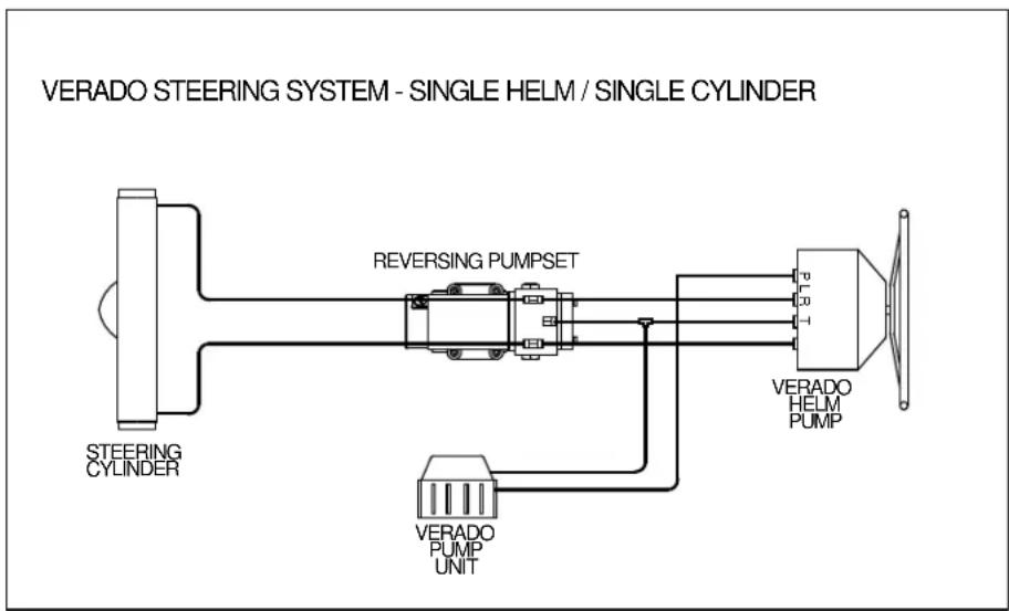
flowchart
graph TD
    A["STEERING CYLINDER"] --> B["REVERSING PUMPSET"]
    B --> C["VERADO HELM PUMP"]
    C --> D["VERADO PUMP UNIT"]
    D --> A
2.2
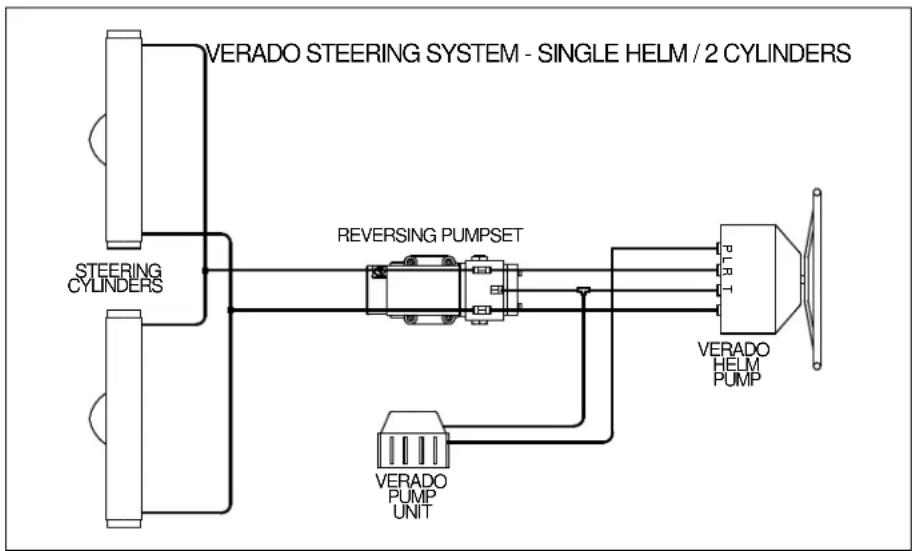
flowchart
graph TD
    A["VERADO STEERING SYSTEM - SINGLE HELM / 2 CYLINDERS"] --> B["STEERING CYLINDERS"]
    A --> C["REVERSING PUMPSET"]
    A --> D["VERADO HELM PUMP"]
    A --> E["VERADO PUMP UNIT"]
2.3
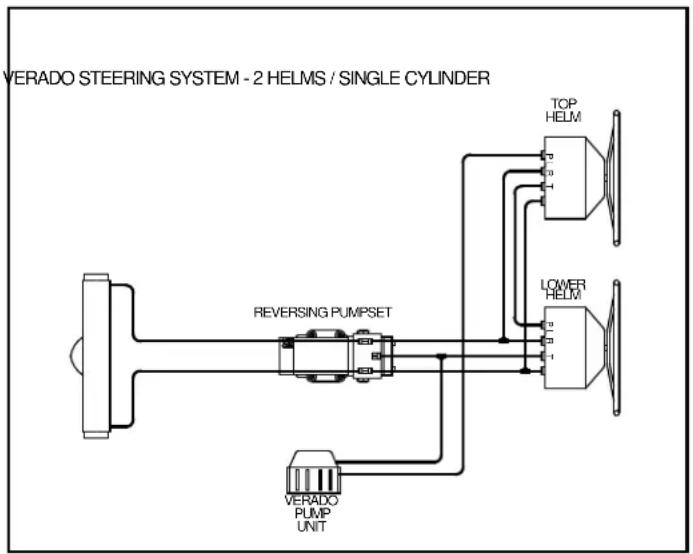
flowchart
graph TD
    A["VERADO STEERING SYSTEM - 2 HELMS / SINGLE CYLINDER"] --> B["REVERSING PUMPSET"]
    B --> C["TOP HELM"]
    B --> D["LOWER HELM"]
    B --> E["VERADO PUMP UNIT"]
2.4
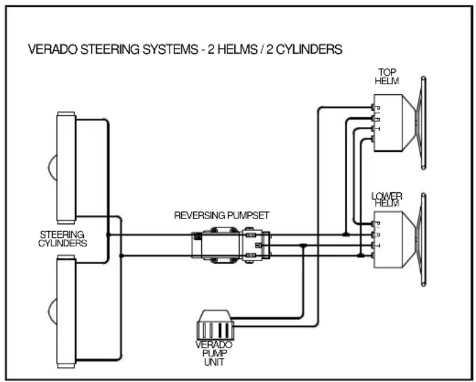
flowchart
graph LR
    A["STEERING CYLINDERS"] --> B["REVERSING PUMPSET"]
    C["VERADO PUMP UNIT"] --> B
    B --> D["TOP HELM"]
    B --> E["LOWER HELM"]
3. SYSTEM DESCRIPTION AND CONNECTIONS
3.1 Oil from the Pump Unit flows to the helm through port
and returns to the Pump Unit from port
3.2 When multiple helm pumps are used the primary circuit lines (P and T) are connected in series, as shown in Figures 2.3 and 2.4. The output ports of the multiple helm pumps (L and R) are connected in parallel.
3.3 The autopilot reversing pumpset is connected in parallel with the helm pump outlets, as shown in one line drawings
3.4 The Tee fittings and adapters (SAE -06 to SAE -04) supplied connect directly to the reversing pumpset using the SAE-06 ports in the pump block.
3.5 The hoses from the helm pump (L and R) are relocated to the outlet fittings in the reversing pumpset. The hosed supplied are connected between the helm pump (L and R) and the other side of the tees on the reversing pumpset.
3.6 The fill line between the lower helm and the Pump Unit is to be cut and a hose barbed tee inserted. Small gear clamps are provided to ensure the hose barb connections do not come apart. The third port from the Tee is connected to the fill port on the reversing pumpset. This fill line should have a gradual slope from the reversing pump to the Tee to allow air to escape from the pumpset.
4. NOTES
Brand : FURUNO
Model : Verado
Category : Uncategorized