
RB411AH - Uncategorized Mikrotik - Free user manual and instructions
Find the device manual for free RB411AH Mikrotik in PDF.


| Product Type | RouterBoard |
| CPU | Atheros AR7161 680MHz |
| RAM | 256 MB DDR2 |
| Storage | 64 MB NAND |
| Wireless | 2.4 GHz 802.11b/g/n (MiniPCI slot) |
| Ethernet Ports | 1x 10/100/1000 Mbps |
| Dimensions | 105 x 105 x 25 mm |
| Weight | 200 g |
| Power Input | 9-28 V DC (via barrel jack) |
| Power Consumption | 12 W max |
| Operating System | MikroTik RouterOS (level 4 license) |
| Main Functions | Router, firewall, VPN, bandwidth management, hotspot |
| Maintenance | Clean with a dry, soft cloth; avoid liquids |
| Safety | Keep away from water and heat sources; use only approved power adapter |
| Spare Parts & Repairability | No user-serviceable parts; contact authorized service center |
| Package Contents | RB411AH unit, power adapter, mounting screws, quick guide |
| Certifications | CE, FCC |
Frequently Asked Questions - RB411AH Mikrotik
User questions about RB411AH Mikrotik
0 question about this device. Answer the ones you know or ask your own.
Ask a new question about this device
Download the instructions for your Uncategorized in PDF format for free! Find your manual RB411AH - Mikrotik and take your electronic device back in hand. On this page are published all the documents necessary for the use of your device. RB411AH by Mikrotik.
USER MANUAL RB411AH Mikrotik
natural_image
Close-up of a green printed circuit board with various electronic components and connectors (no readable text or symbols)Copyright
Copyright © 2003-2008 MikroTikls SIA. This manual contains information protected by copyright law. No part of it may be reproduced or transmitted in any form without prior written permission from the copyright holder.
Trademarks
RouterBOARD, RouterOS, RouterBOOT and MikroTik are trademarks of MikroTikls SIA. All trademarks and registered trademarks appearing in this manual are the property of their respective holders.
Limited Warranty
Copyright and Trademarks. Copyright MikroTikls SIA. This manual contains information protected by copyright law. No part of it may be reproduced or transmitted in any form without prior written permission from the copyright holder. RouterBOARD, RouterOS, RouterBOOT and MikroTik are trademarks of MikroTikls SIA. All trademarks and registered trademarks appearing in this manual are the property of their respective holders.
Hardware. MikroTikls SIA warrants all RouterBOARD series equipment for the term of one year from the shipping date to be free of defects in materials and workmanship under normal use and service, except in case of damage caused by mechanical, electrical or other accidental or intended damages caused by improper use or due to wind, rain, fire or other acts of nature.
If you have purchased your product from a MikroTik Reseller, please contact the Reseller company regarding all warranty and repair issues, the following instructions apply ONLY if you purchased your equipment directly from MikroTik Latvia To return failed unit or units to MikroTikls you must perform the following RMA (Return Material Authorization) procedure. Follow the instructions below to save time, efforts, avoid costs, and improve the speed of the RMA process. Take into account that all goods have one year warranty. Instructions are located on our webpage here:
http://rma.mikrotik.com
Manual. This manual is provided "as is" without a warranty of any kind, expressed or implied, including, but not limited to, the implied warranty of merchantability and fitness for a particular purpose. The manufacturer has made every effort to ensure the accuracy of the contents of this manual, however, it is possible that it may contain technical inaccuracies, typographical or other errors. No liability is assumed for any inaccuracy found in this publication, nor for direct or indirect, incidental, consequential or other damages that may result from such an inaccuracy, including, but not limited to, loss of data or profits. Please report any inaccuracies found to support@mikrotik.com.
Table of Contents
Copyright....1
Trademarks....1
Limited Warranty....1
System Board View....3
System Board Layout....3
Specifications....4
Hardware Guide....4
Memory and Storage Devices....4
Onboard Memory 4
Onboard NAND Storage Device 4
Extension Slots....4
MiniPCI Slots 4
Input/Output Ports 4
LAN1 Port with PoE....4
DB9 Serial Port 5
LEDs....5
Power LED 5
User LED 5
Status LEDs....5
User's Guide....5
Assembling the Hardware....5
Powering....5
Booting options....5
Onboard NAND Storage Device....6
Booting from network....6
RouterBOOT....6
Boot Loader Configuration....6
Configurable Options....7
Boot Loader Upgrading....7
Appendix....7
Serial Null-modem (Console) Cable with Loopback....7
Connector Index....8
Button Index....8
Ethernet Cables....8
RouterBOARD 411 dimensions....11
System Board View
RB411:
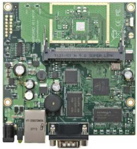
natural_image
Close-up of a green printed circuit board with various electronic components and connectors (no readable text or symbols)Top view Bottom view
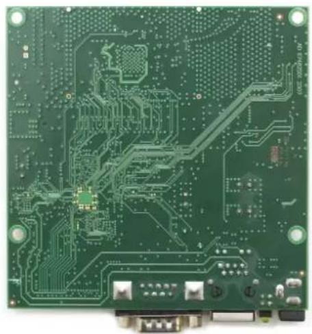
natural_image
Close-up of a green printed circuit board with visible traces, pads, and connectors (no text or symbols)System Board Layout
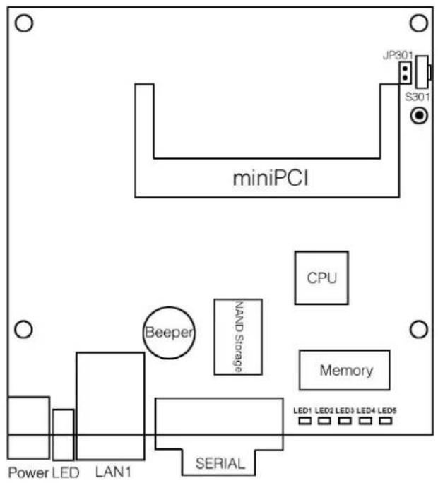
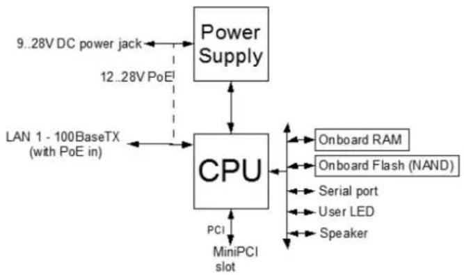
flowchart
graph TD
    A["9..28V DC power jack"] --> B["Power Supply"]
    C["12..28V PoE"] --> B
    D["LAN 1 - 100BaseTX (with PoE in)"] --> E["CPU"]
    E --> F["Onboard RAM"]
    E --> G["Onboard Flash (NAND)"]
    E --> H["Serial port"]
    E --> I["User LED"]
    E --> J["Speaker"]
    E --> K["PCI"]
    K --> L["MiniPCI slot"]
Specifications
| RouterBOARD 411 | |
| CPU MIPS24k based, A | theros AR7130 300MHz CPU |
| Memory 32MB SDRAM | onboard memory |
| Boot loader RouterBOOT | |
| Data storage 64MB onboard NAND memory chip | |
| Ethernet One 10/100 | Mbit/s Fast Ethernet ports supporting Auto-MDI/X |
| MiniPCI slot One MiniPCI Type IIIA/IIIB slot | |
| Serial port One DB9 RS232C asynchronous serial port | |
| LEDs Power and User LED, 5 status LEDs | |
| Speaker Mini PC-Speaker | |
| Power options | Power over Ethernet: 12..28V DC (except power over datalines)Power jack: 9..28V DC |
| Dimensions 105mm x | 105mm |
| Weight 115 g (4.06 oz) | |
| Temperature Operational: -20°C to +65°C (-4°F to 149°F) | |
| Humidity Operational: up to 70% relative humidity (non-condensing) | |
| Power consumption | 3-4W without extension cards, maximum - 14W |
Hardware Guide
Memory and Storage Devices
Onboard Memory
The board is equipped with 32 MB DDR onboard memory.
Onboard NAND Storage Device
The boards are equipped with one 64MB NAND nonvolatile memory chip.
Extension Slots
MiniPCI Slots
The board has one MiniPCI Type IIIA slot with 3.3V only power signaling. It also accepts MiniPCI Type IIIB standard cards. The board has been tested to operate with high power cards if ambient temperature and adequate cooling is ensured.
NOTE: that RB400 series currently does not support Senao 8602 cards, Atheros AR5211 or older chipset and Prism chipset based cards. Wireless compression is not supported on RB400 series devices.
Supplied power for the extension cards (excluding CPU and onboard Ethernet ports):
+3.3V: 3.3A max
Input/Output Ports
LAN1 Port with PoE
This Fast Ethernet port is recognized as the first LAN interface. It is compatible with passive (non-standard) Power over Ethernet. The board accepts voltage input from 12 to 28 V DC. It is suggested to use higher voltages for power over long cables because of better efficiency (less power is lost in the cable itself and power supply is more efficient).
See Connector Index for pinout of the standard cable required for PoE. All cables made to EIA/TIA 568A/B cable specifications will work correctly with PoE. Note that this port supports automatic cross/straight cable correction (Auto MDI/X), so you can use either straight or cross-over cable for connecting to other devices.
DB9 Serial Port
The RS232C standard male DB9 asynchronous serial port may be used for initial configuration, or for attaching a modem or any other RS232 serial device. TxD (pin 3) of this port has -5V DC power when idle. RTS and DTR signals are not connected. Note that the device does not fully implement the hardware (RTS/CTS) flow control, so it is suggested to try to disable hardware flow control in the terminal emulation program in case the serial console does not work as expected, and if it does not help, make a new cable using the pinout given in the User's manual.
LEDs
Power LED
Power LED is on when the board is powered.
User LED
User LED may be programmed at user's option. It is lit by default when the board starts up, then it is turned off when the bootloader runs kernel.
Status LEDs
Five LEDs (LD 501-505) may be used to show bootup activity, wireless signals, and user programmed values.
User's Guide
Assembling the Hardware
First to use the board:
- Insert MiniPCI cards and connect antenna wires, if needed;
•Install the board in a case; - Connect other peripherals and cables.
Powering
Power options:
•J801 power jack:
10..28V DC (supports overvoltage protection)
- Power over Ethernet (PoE) on the J602 LAN1 Ethernet port: 10..28V DC (18..28 V suggested) non-standard PoE powering support
The board has a direct-input power jack J801 (5.5mm outside and 2mm inside diameter, female, pin positive plug) and can as well be powered with PoE. All power inputs are always active, but only one should be used at the same time.
RouterBOARD 411 is equipped with a reliable 14W onboard power supply with overvoltage protection. 9..28 V DC input voltages are accepted, but when powered over long cables, it is suggested to use at least 18V. The system is tested with 24V solar/wind/RV systems with 27.6 charge voltage. Overvoltage protection starts from about 28V (up to 100V), so the board will not be damaged if connected to a 48V or 60V power line.
RouterBOARD 411 series boards are compatible with non-standard (passive) Power over Ethernet injectors (except power over datalines) and accept powering over up to 100m (330 ft) long Ethernet cable connected to the Ethernet port (J602). The board does not work with IEEE802.3af compliant 48V power injectors.
The maximum output of the power supply to the extension cards is normally at about 3.3A
Booting options
First, RouterBOOT loader is started. It displays some useful information on the onboard RS232C
asynchronous serial port, which is set to 115200bit/s, 8 data bits, 1 stop bit, no parity by default. The loader may be configured to boot the system from the onboard NAND module or from Ethernet network. See the respective section of this manual for how to configure booting sequence and other boot loader parameters.
Onboard NAND Storage Device
The RouterBOARD may be started from the onboard NAND storage chip. As there is no partition table on the device, the boot loader assumes the first 4MiB form a YAFFS filesystem, and executes the file called "kernel" stored in the root directory on that partition.
Booting from network
Network boot works similarly to PXE or EtherBoot protocol, and allows you to boot a RouterBOARD 411 series computer from an executable image stored on a TFTP server. It uses BOOTP or DHCP (configurable in boot loader) protocol to get a valid IP address, and TFTP protocol to download an executable (ELF) kernel image combined with the initial RAM disk (inserted as an ELF section) to boot from (the TFTP server's IP address and the image name must be sent by the BOOTP/DHCP server).
To boot the RouterBOARD computer from Ethernet network you need the following:
- An ELF kernel image for the loader to boot from (you can embed the kernel parameters and initrd image as ELF sections called kernparm and initrd respectively)
●A TFTP server which to download the image from - A BOOTP/DHCP server (may be installed on the same machine as the TFTP server) to give an IP address, TFTP server address and boot image name
See the RouterBOOT section on how to configure loader to boot from network.
Note that you must connect the RouterBOARD you want to boot, and the BOOTP/DHCP and TFTP servers to the same broadcast domain (i.e., there must not be any routers between them).
RouterBOOT
The RouterBOOT firmware (also referred as "boot loader" here) provides minimal functionality to boot an Operating System. It supports serial console via the onboard serial port at the boot time. The loader supports booting from the onboard NAND device and from a network server (see the respective section for details on this protocol).
Boot Loader Configuration
Loader parameters may be configured through the onboard RS232C DB9 asynchronous serial interface. To connect to it, use a standard null-modem cable. By default, the port is set to 115200bit/s, 8 data bits, 1 stop bit, no parity. Note that the device does not fully implement the hardware (RTS/CTS) flow control, so it is suggested to try to disable hardware flow control in the terminal emulation program in case the serial console does not work as expected, and if it does not help, make a new cable using the pinout given in the Appendix.
To enter the loader configuration screen, press any key (or only [Delete] key (or [Backspace] key – see the note for the respective configurable option), depending on the actual configuration) just after the loader is asking for it:
RouterBOOT footer 2.12
RouterBoard 411
CPU frequency: 300 MHz
Memory size: 32 MB
Press any key within 2 seconds to enter setup
RouterBOOT-2.12
What do you want to configure?
d-boot delay
k - boot key
s - serial console
o - boot device
u - cpu mode
r - reset configuration
e - format nand
g - upgrade firmware
i - board info
p - boot protocol
t - do memory testing
RouterBOARD 411 Series User's Manual
x - exit setup your choice:
To select a menu point, press the indicated key. Pressing [Enter] selects the option marked with '*'.
Configurable Options
boot delay – how much time to wait for a key stroke while booting (1..9 seconds; 2 second by default).
boot key - which key will cause the loader to enter configuration mode during boot delay (any key |
serial console - to configure initial serial console bitrate (1200 | 2400 | 4800 | 9600 | 19200 | 38400 | 57600 | 115200; 115200 bps by default).
boot device – initial boot device (boot over Ethernet | boot from NAND | boot Ethernet once, then NAND; boot from NAND by default). You can also select boot chosen device option to boot from the device selected immediately, without saving the setting.
cpu mode – whether to enter CPU suspend mode on WAIT instruction (power save | regular; power save by default). Most OSs use WAIT instruction during CPU idle cycle. When CPU is in suspend mode, it consumes less power, but in low-temperature conditions (below 0^ C) it is recommended to choose regular mode, so that overall system temperature would be higher.
reset configuration - whether to reset all the boot loader settings to their respective default values (yes | no; no by default).
format nand - perform a low-level NAND format. During this operation, all previously marked bad sectors are retested to find out if they are faulty indeed.
upgrade firmware – receive a new boot loader image using XModem protocol over serial line or using DHCP/BOOTP and TFTP protocols through the Ethernet network (upgrade firmware over ethernet | upgrade firmware over serial port).
board info - prints the serial number, boot loader version, CPU frequency, memory size and MAC addresses of the onboard Ethernet ports
boot protocol – network booting protocol (bootp protocol | dhcp protocol; bootp protocol by default).
do memory testing – performs a full memory test.
Boot Loader Upgrading
The boot loader is needed to initialize all the hardware and boot the system up. Newer loader versions might have support for more hardware, so it's generally a good idea to upgrade the loader once a newer version is available. You can upgrade the loader through the onboard serial port using XModem protocol (programs available for all major OSs). For example, you can use HyperTerminal for Windows or Minicom for Linux to upload the boot loader. Alternatively if you have a DHCP/BOOTP and TFTP servers available, you can specify the loader image as a boot image and choose the bios upgrade over ethernet option in the boot loader configuration menu. The loader will get the image from the TFTP server and upgrade itself. The most current loader image is available for download on www.routerboard.com.
The boot loader upgrading is supported also from MikroTik RouterOS. The procedure is described in the MikroTik RouterOS manual.Appendix
Serial Null-modem (Console) Cable with Loopback
| DB9f Function DB9f DB25f | ||
| 1 + 4 + 6N/C CD2 RxD | CD + DTR + DSR N+ DTR + DSR 1 +3 2 | N/C N/C4 + 6 6 + 8 + 20 |
| 3 TxD | 2 3 | |
| 5 | GND | 5 7 |
| 7 + 8 | RTS + CTS | N/C N/C |
| N/C | RTS + CTS | 7 + 8 4 + 5 |
Connector Index
| J401 Min | PCI Type type IIIA/B connector | |
| J301 RS2 | 32C male DB9 serial port | |
| 1 | Connected together | |
| 4 | ||
| 6 | ||
| 2 | RxD (Receive Data) | |
| 3 | TxD (Transmit Data) | |
| 5 | GND | |
| 7 | Connected together | |
| 8 | ||
| J602 RJ4 | 5 Fast Ethernet 100Base-TX port LAN1 with passive PoE extension | |
| 1 | Data TX+ | |
| 2 | Data TX- | |
| 3 | Data RX+ | |
| 4 | PoE power + | |
| 5 | PoE power + | |
| 6 | Data RX- | |
| 7 | PoE power - | |
| 8 | PoE power - | |
| J801 Power jack (9..28 V DC, positive contact is the central pin) | ||
Button Index
| S301 Software reset button |
Ethernet Cables
| RJ45 Pin | Color Function RJ45 | pin for Straight cable (MDI, EIA/TIA568A) | RJ45 pin for Crossover cable (MDI-X, EIA/TIA568B) |
| 1 Green TX+ Data 1 3 | |||
| 2 Green/White TX- Data 2 6 | |||
| 3 Orange RX+ Data 3 1 | |||
| 4 Blue - 4 4 | |||
| 5 | Blue/White - | 5 5 | |
| 6 | Orange/White RX- Data | 6 2 | |
| 7 | Brown - | 7 7 | |
| 8 | Brown/White - | 8 8 | |


- Copyright
- Trademarks
- Limited Warranty
- http://rma.mikrotik.com
- Table of Contents
- System Board View
- System Board Layout
- Hardware Guide
- Memory and Storage Devices
- Onboard Memory
- Onboard NAND Storage Device
- Extension Slots
- MiniPCI Slots
- Input/Output Ports
- LAN1 Port with PoE
- DB9 Serial Port
- LEDs
- Power LED
- User LED
- Status LEDs
- User's Guide
- Assembling the Hardware
- Powering
- Booting options
- Booting from network
- RouterBOOT
- Boot Loader Configuration
- RouterBOARD 411 Series User's Manual
- Configurable Options
- Boot Loader Upgrading
- Serial Null-modem (Console) Cable with Loopback
Brand : Mikrotik
Model : RB411AH
Category : Uncategorized