
B5100D - Uncategorized KUBOTA - Free user manual and instructions
Find the device manual for free B5100D KUBOTA in PDF.


| Product Type | Compact Utility Tractor |
| Brand | Kubota |
| Model | B5100D |
| Engine Type | 1-cylinder, 4-stroke diesel |
| Engine Displacement | 0.5 L (500 cc) |
| Power Output (Engine) | 13.5 hp (10.1 kW) |
| Power Output (PTO) | 11 hp (8.2 kW) |
| Fuel Type | Diesel |
| Cooling System | Liquid-cooled |
| Drive Type | 2WD (rear wheel drive) |
| Dimensions (L x W x H) | 2260 x 1060 x 1300 mm |
| Weight | 485 kg (1070 lbs) |
| Wheelbase | 1350 mm |
| Ground Clearance | 290 mm |
| Fuel Tank Capacity | 15 L (3.3 gal) |
| Transmission Type | Sliding gear, 4 forward / 1 reverse |
| Steering Type | Manual (recirculating ball) |
| Brake Type | Mechanical, wet disc |
| Hydraulic Capacity | 6.5 L |
| Safety Features | Seat switch, PTO shield, ROPS (optional) |
| Maintenance Interval | Engine oil every 50 hours; transmission fluid every 200 hours |
| Parts Availability | Widely available through Kubota dealers and online |
Frequently Asked Questions - B5100D KUBOTA
User questions about B5100D KUBOTA
0 question about this device. Answer the ones you know or ask your own.
Ask a new question about this device
Download the instructions for your Uncategorized in PDF format for free! Find your manual B5100D - KUBOTA and take your electronic device back in hand. On this page are published all the documents necessary for the use of your device. B5100D by KUBOTA.
USER MANUAL B5100D KUBOTA
B5100D·B6100D·B7100D
B5100E·B6100E
MANUEL DE L'UTILISATEUR
TRACTEUR KUBOTA
MODELE
B5100D·B6100D·B7100D
B5100E·B6100E

natural_image
Black-and-white photo of a HUBOTA 91R tractor with large tires and headlamps, displayed against a green background (no visible text or symbols on the vehicle itself)Kubota, Ltd. is...
Since its inception in 1890, Kubota, Ltd. has grown to rank as one of the major firms in Japan.
To achieve this status, the company has through the years diversified the range of its products and services to a remarkable extent, until today, 19 plants and 19,000 employees produce over 1,000 different items, large and small.
All these products and all the services which accompany them, however, are unified by one central commitment. Kubota makes products which, taken on a national scale, are basic necessities. Products which are indispensable, products intended to help individuals and nations fulfill the potential inherent in their environment. For Kubota is the Basic Necessities Giant.
This potential includes water supply, food from the soil and from the sea, industrial development, architecture and construction, transportation.
Thousands of people depend on Kubota's know-how, technology, experience and customer service. You too can depend on Kubota.
Kubota Makes all Kinds of Agricultural Machinery for Seeding to Harvesting.
●Radiator-Cooled Diesel Engines
●A r-Cooled Gasoline Engines
●Power Tillers ●Farm Tractors ●Power Sprayers
●Power Mist Blower & Dusters ●Brush Cutters ●Dairy Machines
●Sprinklers ●Rain Guns ●Pumps ●Others

CAUTION
-
Keep all shields in place.
-
Before leaving operator's position:
a. Shift transmission to neutral
b. Set parking brake
c. Disengage attachment clutch or shift PTO speed change lever to neutral.
d. Shut off engine
e. Remove main switch key
-
Wait for all movement to stop before servicing machine.
-
Keep people and pets a safe distance away from machine.

PRECAUTIONS
You are now the proud owner of a Kubota B5100D/B5100DT/B5100E/96100D/96100E/B7100D/B7100DT Tractor. This tractor is a product of Kubota quality engineering and manufacturing. It is made of the finest materials and under rigid quality control system. It will give you long, satisfactory service. To obtain the best use of your Kubota Tractor, please read this manual carefully. It will help you become familiar with the operation of the tractor, and contains many helpful hints about tractor maintenance. It is Kubota's policy to utilize as quickly as possible every advance in our research. The immediate use of new technique in the manufacture of products may cause some small parts of this manual to be outdated. Kubota distributors and dealers will have the most up-to-date information. Please do not hesitate to consult with them.
PREFACE
For safety operation, be sure to observe the following directions and precautions.
First of all, please read this Owner's Manual carefully and get familiar with your Kubota Tractor. Every time you drive it, ensure that everything is in order. The following are general safety precautions to prevent accidents and troubles. Later in this manual you will find other particular safety precautions related to individual operations.
1. FUEL SUPPLY AND ENGINE START
(1) Always stop the engine before refueling.
(2) To avoid the danger of exhaust fume poisoning, do not keep the engine running for a long time in a closed garage.
(3) Before starting the engine, mount the driver's seat, disengage the clutch and put the main and high-low gear shift levers and PTO speed change lever into neutral.
2. STARTING
When starting the tractor, check to see that there are no people around. To back the tractor, first check to see that there are no obstacles around it and slow down the engine.
3. OPERATION
(1) Unreasonable driving such as operation on a slope or under an extremely heavy workload may tip the tractor over.
12) Keep the safety cover on, otherwise a hand or finger may be caught by rotating parts.
(3) When working in cooperation with other tractors, let the other drivers know what you are doing at every job start and end.
(4) Keep people away from the tractor during operation.
(5) When using a heavy implement, be sure to fit the tractor with the prescribed front weight.
4. LOADING AND UNLOADING
(1) Securely fix a rugged ramp with non-skids and check to see that there are no people around before starting to load or unload.
(2) To prevent a truck to be loaded or unloaded from moving, be sure to apply the truck side brake securely.
5. TRAVELLING
(1) When travelling on the road, be sure to interlock the two brake pedals. Uneven braking may cause sudden swerves or the tractor to slip over.
(2) When descending a slope, never disengage the clutch or shift the main gear shift lever to neutral to avoid overspeeding.
(3) When driving into a field of greatly different ground level from the road, use a ramp to avoid tipping the tractor over.
(4) When travelling on the public road, observe the traffic regulations and proper conduct.
[5] At corners, always slow down the tractor before turning. Turning at a high speed may tip the tractor over.
(6) Do not drive with your foot on the clutch pedal all the time.
(7) Do not apply the differential lock while travelling.
(8) When travelling on a road or slope, widen the rear wheel tread outermost.
(9) To transport the rotary tiller or other heavy implement, be sure to lift it with the provided chain.
6. OPERATING WITH ROTARY TILLER
(1) To check and/or change tiller blades, do the following: - Stop the engine.
- Prevent: the sudden drop of the rotary tiller by hoisting it up with the chain.
- Apply the parking brake.
(2) When attaching and/or adjusting the rotary tiller on the tractor, observe the following:
- Do not stand between the tractor and the implement
- Check to see that the 3-point (2-point) hitch pins and the universal joint lock pin are securely fitted.
[3] When working with the rotary tiller, observe the following directions:
- Keep your hands away from rotating parts such as the blade shaft and universal joint.
- Do not climb the rotary tiller.
- Check to see that nothing is interfering when lifting, backing or turning the rotary tiller.
(4) When climbing a slope or going over a bank with an implement on the tractor, lower the implement to prevent the tractor from head up.
(5) If the tractor lunces while rotary-tilling a hard ground, immediately step on the clutch and brake pedals. Next, put the engine in low gear and start tilling again at a high PTO shaft speed.
7. OTHER PRECAUTIONS
(1) Do not drive the tractor in the following state:
- when you are drunk, - when you are sleepy
- when you feel sick or after taking medicine,
■ when you are pregnant,
[2] Avoid driving the tractor in loose, barley clothes.
(3) Check, service or clean the tractor after stopping the engine, follow the directions of the Owner's Manual.
(4) Avoid touching the muffler and the radiator during or immediately after running, or you may be scalded. Service or check the tractor after it has completely cooled off.
(5) When working in the fields or muddy areas, be sure to scrape off mud or soil from the bottom of your shoes before mounting the tractor. Otherwise your feet may slip on the brake or clutch pedals.
(6) When allowing other people to use your tractor, explain the handling well and lend this manual beforehand.
efore using implement not purchased with tractor, intact your nearest dealer for instructions in safety. se 2nd or 3rd PTO gear if such speed is recommended in bel, implement manual, or other instructions. Otherwise, se only 1st gear.
OUTSTANDING FEATURES CARACTERISTIQUES EXCEPTIONNELLE
des comprimés
■ 4-wheel drive with large-size tires
The 4-wheel drive with large-size tires B5100D-B6100D (rear 7-16)/B7100D (rear 8-16) significantly makes for powerful drive and traction—efforties even on wet fields and slopes.
* Front lug tires enable pudding without the need for a chain.
* Unrivalled climbing and traction power.
■ Comfortable ride
A combination of 3-cylinder diesel engine B6100D/B6100E/B7100D, large size muffler and bucket-type driver's seat cut vibrations and noises to a negligible extent.
- Wide step
- Horizontal-upright convertible muffler
■ Simple, effortless control
(1) Both hand and foot acceleration controls
(2) Light, sharp ball screw type steering system (3) Ample driver's seat and wide step
■ Safety design
* Well-balanced front and rear
* Engine entirely enclosed by safety cover
* Thermal insulation cover for muffler
* Large-size fenders, hand rails
■ Options
* Extension muffler
• Implement lock chain
* Hour meter (B5100E/B6100E)
* Hydraulic circuit changeover unit (B5100E)
| Model: | B5100D | B5100D | 35100E | B5100E T | B6100D | B6100E | B6100E T | B7100D | B7100D T | |
| Engine: | KUBOTA Z500-1A | KUBOTA D650-A | KUBOTA D750-A | |||||||
| Type: | Vertical, water-coated, 4-cycle engine | |||||||||
| Cylinders: | 2 | 3 | ||||||||
| Total displacement | 508 cm3 | 575 cm3 | 762 cm3 | |||||||
| Bare horse power and shed | 8.8 kW and 50 rA (112HP and 3300 rpm) | 10.3 kW and 46.7 r/y (14 HP and 2800 rpm) | 11.7 kW and 46.7 r/s(16HP and 2800 rpm) | |||||||
| Cylinder bore and stroke | 68 x 70mm | 64 x 70mm | 62 x 70mm | |||||||
| Fuel: | High speed diesel fuel or No. 2 diesel fuel | |||||||||
| Starter: | Electric starter with battery, glow plug and decromission device, 12V, 0.8kW | |||||||||
| Lubrication: | Forced transmission by tripholidal pump | |||||||||
| Cooling: | Water with pressurized radiator | |||||||||
| Battery: | 12V 35Ah | 12V 45Ah | ||||||||
| Fuel tank cap: | 8 ft (7.8 ft steel tank type) | 13 ft (10 ft steel tank type) | ||||||||
| Engine oil tank cap: | 2.3 ft | 3.4 ft | ||||||||
| Engine coolant cap: | 2 ft | 4.6 ft | ||||||||
| Transmission oil case cap: | 0.5 ft | 11.5 ft | ||||||||
| Dimensions: | ||||||||||
| Overall length: | 1820 mm | 1810 mm | 1980 mm | 1930 mm | 1890 mm | 1975 mm | ||||
| Overall width: | 320 mm(tire outer width) | 920 mm(tire outer width) | 940 mm(tire outer width) | 965 mm(tire outer width) | 940 mm(tire outer width) | 1120 mm(tire outer width) | ||||
| Overall height: | 1120 mm | 1125 mm | 1120 mm | 1130 mm | 1135 mm | 1120 mm | 1150 mm | 1135 mm | ||
| Wheel base: | 1200 mm | 1250 mm | 1240 mm | 1250 mm | ||||||
| Minimum ground clearance: | 260 mm(to transmission case bottom);220 mm(to front axle) | 230 mm(to transmissioncase bottom) | 250 mm(to transmissioncase bottom);240 mm(to front axle) | 250 mm(to transmissioncase bottom) | 220 mm(to transmissioncase bottom) | 280 mm(to transmissioncase bottom);240 mm(to front axle) | 265 mm(to transmissioncase bottom);220 mm(to front axle) | |||
| Treads | Front | 745 mm | 870 mm | 660 mm | 740 mm | 735 mm | 695 mm | 780 mm | 735 mm | 925 mm |
| Rear | 745 mm | 840 mm, 742 mm | 745 mm | 660 mm, 710 mm, 730 mm | 815 mm | |||||
| Tires | Front | 20 x 8.00-13 | 4.50 10 2PR | 4.30 9 2PR | 20 x 8.00-10 | 6.12 2PH | 4.00 9 2PH | 20 x 8.00-10 | 6.12 2PH | 20.5 x 8.00-10 |
| Rear | 212/800-15 | 7-16 4PR | 27 x 8.50-15 | 7-16 4PR | 27 x 8.50-15 | 8-16 4PR | 23 x 12 60 15 | |||
| Weight: | 405 kg | 405 kg | 375 kg | 470 kg | 440 kg | 450 kg | 490 kg | 520 kg | ||
| PTO shift: | ||||||||||
| Location: | Transmission case rear 1 (Engine front 1) | |||||||||
| Ground clearance: | 450 mm | 420 mm | 445 mm | 415 mm | 470 mm | |||||
| Revolution direction: | Right viewed from rear | |||||||||
The image contains no text. The horizontal line is a stylistic or background element and must be ignored according to the rules.
[Non-Text]
| Revolution | *1 | 2 steps-10.3 and 16.1 r/s at 50 engine r/s (603 and 963 rpm at 3000 engine rpm) | 3 steps-8.6, 14.6 and 29.0 r/s at 45.7 engine r/s (514, 878 and 1498 rpm at 2800 engine rom) | *2 | ||
| Clutch: | Dry single alate type | |||||
| Steering: | Ball screw type | |||||
| Transmission: | Gear shift | |||||
| Speed changes: | 6 forward, 2 reverse | |||||
| Minimum turning radius | 1.68 m | 1.65 m | 1.85 m | 1.75 m | 1.6 m | |
| Brake: | Internal-expanding type, right end left independent with interlocking device | |||||
| Differential devices: | Bevel gear type (both for front and near wheels) | Bevel gear type (only for rear wheels) | Bevel gear type (both for front and rear wheels) | Bevel gear type (only for rear wheels) | Bevel gear type (both for front and near wheels) | |
(1) 2.360s=8.0, 14.8 and 26.0 r/s at 45.7 engine r/s 1514, 878 and 1498 rom at 2800 engine rpm
■ Travelling Speed
| Gear shift | Travelling speed | Uses | |||||||||
| m/s | km/h | ||||||||||
| B5100D B5100E | B5100E-T | B6100D B6100E | B6100E-T | B7100D | B5100D B6100E | B5100E-T | B6100D B6100E | B6100E-T | B7100D | ||
| 1st | 0.26 | 0.23 | 0.29 | 0.26 | 0.27 | 0.94 | 0.85 | 1.04 | 0.95 | 0.98 | History stilling, lavelling, ridging |
| 2nd | 0.44 | 0.40 | 0.49 | 0.45 | 0.46 | 1.80 | 1.47 | 1.77 | 1.62 | 1.67 | History stilling, levelling |
| 3rd | 0.72 | 0.66 | 0.84 | 0.77 | 0.79 | 2.62 | 2.40 | 3.02 | 2.77 | 2.85 | Rotary, furrowing, pudding |
| 4th | 1.27 | 1.16 | 1.31 | 1.21 | 1.24 | 4.58 | 4.20 | 4.74 | 4.34 | 4.46 | Puddling, powing |
| 5th | 2.18 | 2.00 | 2.24 | 2.06 | 2.11 | 7.85 | 7.20 | 8.06 | 7.41 | 7.61 | Picking |
| 6th | 3.56 | 3.27 | 3.64 | 3.52 | 3.62 | 12.84 | 11.77 | 13.82 | 12.67 | 13.02 | Trailing work |
| R1 | 0.36 | 0.33 | 0.42 | 0.39 | 0.42 | 1.31 | 1.20 | 1.52 | 1.39 | 1.43 | |
| R2 | 1.78 | 1.63 | 1.93 | 1.77 | 1.82 | 6.43 | 5.89 | 6.95 | 6.37 | 6.55 | |
■ Travelling Speed [Sweden, Denmark, Finland, Norway]
| Gear shift | Trwelling speed | Uses | |||||||
| m/s | sm/h | ||||||||
| BS1000BS1000T | BS1000-TBS1000-T | B7100D | B71000-T | BS1000DSB100F | BS1000-TBS1000-T | B7100D | B71000-T | ||
| 1st | 0.26 | 0.25 | 0.27 | 0.26 | 0.94 | 0.91 | 0.98 | 0.93 | Rotary tilling, levelling, ceiling |
| 2nd | 0.44 | 3.43 | 3.46 | 0.44 | 1.60 | 1.56 | 1.67 | 1.56 | Rotary tilling, swelling |
| 3rd | 2.03 | 2.91 | 1.06 | 1.01 | 3.34 | 3.76 | 3.83 | 3.83 | Rotary turlowing, pudding |
| 4th | 1.71 | 1.24 | 1.24 | 1.39 | 4.58 | 4.27 | 4.46 | 4.27 | Padding, plowing |
| 5th | 2.18 | 2.13 | 2.11 | 2.02 | 7.85 | 7.67 | 7.81 | 7.28 | Plowing |
| 6th | 4.56 | 4.45 | 4.88 | 4.63 | 18.4 | 16.02 | 17.57 | 16.95 | Tracing work |
| R1 | 0.36 | 0.35 | 0.40 | 0.36 | 1.31 | 1.26 | 1.43 | 1.38 | |
| R2 | 1.78 | 1.74 | 1.82 | 1.73 | 8.43 | 6.77 | 6.95 | 6.21 | |
★ The Kubota B5100D/B6100D/B7100D is shipped with a choice of the following ★ The Kubota B5100E/B5100E-T/B6100C/B6100E-T is shipped with a choice of
the following accessory assortments:
Tractor
(3) B5100E-P/B5100E-PT
(4) B6100E-P/B6100E-PT Tractor and 3-point hitch
Tractor and 3-point hitch
10. EBITDA
The image is too blurry to recognize any text content.
[Unreadable]
©
⑥
②
The image is too blurry to recognize any text content.
-
[Non-Text]
[Non-Text]
[Non-Text]
•
-
-
-
-
[Non-Text]
[Non-Text]
[Non-Text]
[Non-Text]
[Non-Text]
[Non-Text]
[Non-Text]
[Non-Text]
[Non-Text]
[Non-Text]
[Non-Text]
[Non-Text]
[Non-Text]
[Non-Text]
[Non-Text]
[Non-Text]
[Non-Text]
[Non-Text]
[Non-Text]
-
[Non-Text]
[Non-Text]
[Non-Text]
[Non-Text]
[Non-Text]
-
The image is too blurry to recognize any text content.
[Non-Text]
-
[Non-Text]
[Non-Text]
©
广力云智慧零售收银系统
-
-
-
The Ground Truth image displays a single, solid horizontal line. According to Rule 2 (UNDERSCORE & LINE RULES), this is a stylistic or background line, not a placeholder underscore. Therefore, the OCR result must ignore it and output nothing or only meaningful text. The provided OCR content is "____", which consists of four underscores. This is an incorrect interpretation of the line as a placeholder, violating the rule that stylistic lines must be ignored. The OCR has hallucinated underscores where none should exist based on the GT's visual context. Hence, the OCR result is inconsistent with the Ground Truth.
-
-
[Non-Text]
[Non-Text]
[Non-Text]
[Non-Text]
[Non-Text]
[Non-Text]
[Non-Text]
[Non-Text]
[Non-Text]
[Non-Text]
[Non-Text]
[Non-Text]
[Non-Text]
[Non-Text]
[Non-Text]
[Non-Text]
[Non-Text]
[Non-Text]
[Non-Text]
-
[Non-Text]
[Non-Text]
[Non-Text]
The Ground Truth image displays a single, solid horizontal line. According to Rule 2 (UNDERSCORE & LINE RULES), this is a stylistic or background line, not a placeholder underscore. Therefore, the OCR result must ignore it and output nothing or only meaningful text. The provided OCR content is "____", which consists of four underscores. This is an incorrect interpretation of the line as a placeholder, violating the rule that stylistic lines must be ignored. The OCR has hallucinated underscores where none should exist based on the GT's visual context. Hence, the OCR result is inconsistent with the Ground Truth.
[Non-Text]
[Non-Text]
)
m = 311
-
-
广力云智慧零售收银系统
[Non-Text]
[Non-Text]
)
[Non-Text]
©
-
-
-
m = 311
-
广力云智慧零售收银系统
[Non-Text]
[Non-Text]
[Non-Text]
[Non-Text]
[Non-Text]
[Non-Text]
[Non-Text]
[Non-Text]
[Non-Text]
[Non-Text]
[Non-Text]
[Non-Text]
[Non-Text]
[Non-Text]
[Non-Text]
[Non-Text]
[Non-Text]
[Non-Text]
[Non-Text]
-
[Non-Text]
[Non-Text]
[Non-Text]
[Non-Text]
[Non-Text]
[Non-Text]
[Non-Text]
[Non-Text]
[Non-Text]
[Non-Text]
-
[Non-Text]
[Non-Text]
)
[Non-Text]
-
[Non-Text]
[Non-Text]
[Non-Text]
[Non-Text]
[Non-Text]
[Non-Text]
[Non-Text]
[Non-Text]
[Non-Text]
[Non-Text]
[Non-Text]
[Non-Text]
[Non-Text]
[Non-Text]
[Non-Text]
[Non-Text]
[Non-Text]
[Non-Text]
[Non-Text]
)
[Non-Text]
广力云智慧零售收银系统
[Non-Text]
[Non-Text]
[Non-Text]
[Non-Text]
[Non-Text]
[Non-Text]
[Non-Text]
[Non-Text]
-
[Non-Text]
[Non-Text]
[Non-Text]
[Non-Text]
[Non-Text]
[Non-Text]
[Non-Text]
[Non-Text]
[Non-Text]
[Non-Text]
[Non-Text]
[Non-Text]
[Non-Text]
-
-
-
The Ground Truth image displays a single, solid horizontal line. According to Rule 2 (UNDERSCORE & LINE RULES), this is a stylistic or background line, not a placeholder underscore. Therefore, the OCR result must ignore it and output nothing or only meaningful text. The provided OCR content is "____", which consists of four underscores. This is an incorrect interpretation of the line as a placeholder, violating the rule that stylistic lines must be ignored. The OCR has hallucinated underscores where none should exist based on the GT's visual context. Hence, the OCR result is inconsistent with the Ground Truth.
广力云智慧零售收银系统
[Non-Text]
[Non-Text]
[Non-Text]
[Non-Text]
[Non-Text]
[Non-Text]
[Non-Text]
)
[Non-Text]
-
[Non-Text]
[Non-Text]
[Non-Text]
[Non-Text]
[Non-Text]
[Non-Text]
[Non-Text]
[Non-Text]
[Non-Text]
[Non-Text]
[Non-Text]
[Non-Text]
[Non-Text]
-
-
-
-
广力云智慧零售收银系统
[Non-Text]
[Non-Text]
[Non-Text]
[Non-Text]
[Non-Text]
[Non-Text]
[Non-Text]
[Non-Text]
[Non-Text]
[Non-Text]
[Non-Text]
[Non-Text]
[Non-Text]
-
-
-
The Ground Truth image displays a single, solid horizontal line. According to Rule 2 (UNDERSCORE & LINE RULES), this is a stylistic or background line, not a placeholder underscore. Therefore, the OCR result must ignore it and output nothing or only meaningful text. The provided OCR content is "____", which consists of four underscores. This is an incorrect interpretation of the line as a placeholder, violating the rule that stylistic lines must be ignored. The OCR has hallucinated underscores where none should exist based on the GT's visual context. Hence, the OCR result is inconsistent with the Ground Truth.
1
-
[Non-Text]
[Non-Text]
[Non-Text]
[Non-Text]
[Non-Text]
[Non-Text]
[Non-Text]
[Non-Text]
[Non-Text]
[Non-Text]
[Non-Text]
[Non-Text]
-
-
-
广力云智慧零售收银系统
[Non-Text]
[Non-Text]
[Non-Text]
[Non-Text]
[Non-Text]
[Non-Text]
[Non-Text]
5.1 Daily check 21
5. 2 Breaking-in (The first 60 hours of operation) .... 22
5.3 Periodic check 22
- CHECK AND MAINTENANCE 24
6.1 Fuel 24
6.2 Engine oil 39
6.3 Transmission oil 30
6. 4. Changing front axle case oil
(05100D/68100D/B7100D) 31
6.5 Changing front wheel gear case oil
(Right and left) (BG1000/B61000/B71000) , . . . 32
6. 6 Oiling and grossing points before starting ..... 32
6.7 Radiator 35
6. B. Tre pressure 38
6.9 Air cleaner 39
6.10. Battery 39
- ADJUSTMENTS 41
7.1 Belt tension....41
7.2 Clutch 42
7.3 Brake 43
7.4 Steering wheel 44
7.5 Implement lowering speed 48
7. 6 Implement lifting and lowering limits ..... 48
7. 7 Rear wheel tried 48
7.8 Toe-in 46
7.9 Center pin....47
7.10 Exhaust pipe with muffler
- TROUBLESHOOTING 48
8.1 Battery troubleshooting....48
8.2 Engine troubleshooting 49
-
LONG-TERM STORAGE 52
-
3-POINT HITCH .... 63
10.1 Fitting 3-point hitch
10.2 3-point hitch adjustment ..... 58
- OPTIONS 57
-
WIRING DIAGRAM 59
-
OFFRES DE SERVICE DU VENDEUR 1
-
IDENTIFICATION DES PIECES IMPORTANTES .... 2
-
TABLEAU DE BORD ET CONTROLES.... 3
[85100D/B610CD/B7100D] 3
Your dealer is interested in your new tractor and has the desire to help you get the most value from it. After reading this manual thoroughly, you will find that you can do many of the regular service jobs quickly and easily.
However, when in need of parts or major service, be sure to see your KUBOTA dealer.
When in need of parts, be prepared to give your dealer both the tractor and engine serial numbers.
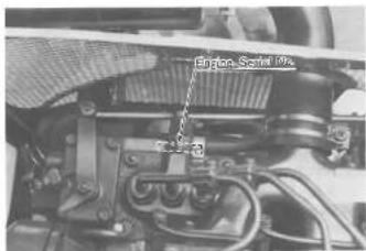
The tractor serial number is located on the clutch housing case, left side. The engine serial number is located on the engine crankcase, right side.
Locate the serial numbers now and record them in the space provided
KUBOTA B5100C/B5100E/B6100D/B6100E/B7100D TRACTOR
Tractor Serial No. ____ Engine Serial No. ____
Date of Purchaser
(To be filled in by purchaser)

TRACTEUR KUBOTA BS100D/BS100E/B6100D/
6100E/B7100D
natural_image
Close-up of a mechanical assembly with no visible text or symbols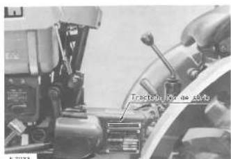
Inserting the key and turning it one click to the right closes the electrical circuit and lights up the engine oil pilot lamp (RED). Depress the clutch pedal and disengage the clutch. Next, turning the key left activates the glow plug (preheating coil), procured to preheat the combustion charger. After ascertaining that the glow lamp has turned red and that the engine has been preheated completely, turn the key switch right and the oil starter will start to rotate and the engine will then start. Release the key switch and it will return to the home position ⊙.
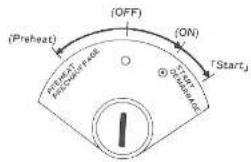
■ Glow Lamp
Turn the key switch left and the glow lamp will start turning red, indicating that the engine is preheating.
3.1 INTERRUPTEURS
Contact
■ Hour Meter (B5100E/B6100E: Option)
As the hour meter works electrically, it starts to work when the key switch is turned to ON or PREHEAT.
■ Front Lamp Switch
Turning the front lamp switch to the right illuminates the front lamps.
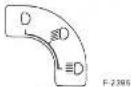
■ Position Lamp Switch (B6100D/B6100E/B7100D)
Turn on the position lamp switch and the position lamp lights up.
■ Horn Button
Turning the key switch one click to the right then pressing the horn button (BLACK) sounds the horn.
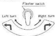
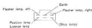
■ Flasher Lamp
(1) Throwing the flasher switch lever to the right or left turns on the flasher lamp. (2) After completing a right or left turn, throw the switch lever back to neutral.
■ Decomp Knob
In the event the cell starter is difficult to turn because of dull battery or cold weather, pull the decomp knob to decompress the engine, speed up the engine to the high speed by driving the cell starter, then push back the decomp knob. With this procedure the engine will start much more easily.
■ Engine Oil Pilot Lamp (RED)
The function of the engine oil pilot lamp is to indicate if engine oil pressure is normally distributed throughout the engine, if it goes on when the key switch is turned on, and goes off when the engine starts and the engine oil is ready to circulate normally.
■ Charge Lamp (B6100D/B6100E/B7100D)
The function of the charge lamp is to indicate if the dynamo is operating. The lamp glows red when the dynamo is not operating.
opening the bonnet reveals the 5-ampere and 15-ampere fuses on the rear of the instrument panel) which safeguards the electrical circuit. When the fuse (s) is blown, examine the cause of the overcurrent, eliminate the trouble and replace with a new fuse. After that, ensure normal amperage. (Spare fuses are provided with new tractor.)

Electrical Coupler
he electrical coupler is used when connecting a trailer or the ke.

natural_image
Close-up of a mechanical assembly with gears and levers (no visible text or symbols)s mating coupler is provided in the accessory bag.
■ Fusibles
natural_image
Close-up of a mechanical assembly with visible gears and shafts (no text or symbols)[Sweden, Denmark, Finland, Norway]

■ Temperature Gauge (B7100)
This indicates the engine temperature.
[CAUTION]
- If the indicator should go over RED zone, the engine must be stopped until the cause of the overheating is corrected.
(Such as quantity of cooling water, fan belt loosening) (1) After operating the engine, never touch radiator until it has had sufficient time to cool.
(2) Check this temperature gauge frequently as you operate.

This meter shows the number of hours the tractor has been operated at rated engine rpm.
The last digit (white background) indicates 1/10 of an hour. The time in minutes will be shown by multiplying by six to last digit on white background.
Example 1701... 170 hours 6 minutes used
Moving hand indicates the revolution per minute of the engine.

Fuel Gauge
When the key switch is on, the fuel gauge indicates the fuel level.

F-2069
![Clutch pedal Pâscale d'embrayage Main gear shift lever Levier principal de changement de vitesse PTO speed-large lever Levier de vitesse de vitesse High low gear shift lever Levier de vitesse fort et ramp [BS100D;AS100E] [BS100D;AS100E] Bode pedal (left) Bode de frein (gauche) Bode pedal (right) Bode de frein (droite) Accelerator pedal Pâscale d'acceleratur Parkit brake lever Fren à rain Diferetior lock pedal Pâscale de l'oucage du differentiel Front wheel de ve lever Lever lechtragement des rods annul. (BS100D;BS100D;B7100D) High flow gear shift lever Levier de vitesse fonte et rapide (BS100D;BS100C;B7100D)](/content/2026/05/1004758/images/a6ca1027f4112dc0c313da4ae0e3863a80b7ec166ee4431b5fdfa67f23b8abc5.jpg)
3.2 CONTROLS
■ Accelerator Lever and Pedal
Throwing the accelerator lever backward slows down the engine and throwing it forward speeds up the engine. In addition, the engine is speeded up by stopping on the accelerator pedal with the accelerator lever left in the backward position. To stop the engine, pull the engine stop lever (release arm).
The engine is stopped either by pulling the stop-lever back or by pulling back on the "Pull To Stop" knob.
To start the engine, the "Pull To Stop" knob is first lifted then pushed forward.

3.2 CONTROLES
Operating the hydraulic control lever activates the hydraulic lift arm, which controls the elevation of the tractor implement. Throwing the lever forward lowers the implement and throwing it backward raises the implement. When the implement reaches the upper or lower limit, the lever automatically returns to the neutral position. In addition, when the lever is brought to the neutral position while the implement is moving up or down, the implement stops and remains at that level.
(1)

■ Main Gear Shift Lever and High-Low Gear Shift Lever
The main gear shift lever positions are of H-configuration and the high-low gear shift lever positions of I-configuration. Combined operation of both speed control lever makes possible 6-forward speed changes and 2 reverse speed changes. Specifically, 3 forward speeds and one reverse speed are achieved with the high-low gear shift lever set at LOW while 4th to 8th forward speeds and 2nd reverse speed are achieved with the high-low gear shift lever set at HIGH.
B6100D/B6100E/B7100D B5100D/B5100E


O shaft speed is controlled in 3 steps (B6100D/B6100E/100D), 2 steps (B5100D/B5100E). To change PTO shaft led, be sure to stop on the clutch pedal to disengage the tch.
weden, Denmark, Finland, Norway)
O shaft speed is controlled in 2 steps (B6100D/B7100D).
AUTIONS:
When using a rotary tiller, use only 1st gear for rotating in extremely hard or rocky field. Otherwise, troubles may occur. Also this would ensure smooth operation and maximum possible depth.
I Never use PTO 2nd or 3rd gear except following the instruction of the implements.
When necessary PTO to use PTO 2nd or 3rd gear, adjust the restricting plate as follows. (B6100C/B6100E/B7100D). - When use 2nd gear, loogan the bolt and slide the plate forward.
- When use 3rd gear, take off the plate
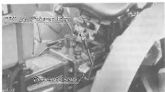
Front Wheel Drive Lever (B5100D/B6100D/B7100D)
he front wheel drive lever is used in the event that greater action power is required on a slope or a wet field or that the sector must be prevented from lunging during rotary-tilling and soil.
owering the lever drives the front wheels-4 wheel drive.

natural_image
Close-up of a tractor's wheel and suspension system (no visible text or symbols)(B5100D/B6100D/B7100D)
Fully stepping on the pedal disengages the clutch off the power transmission.

CAUTION:
(1) The clutch pedal must quickly be stepped on and slowly be released.
(2) Be sure to release the clutch pedal while the tractor in motion in the wake of speed change.
SAFETY PRECAUTIONS:
Whenever changing speed, be sure to step on the clutch pedal.
■ Brake Podals (Right and Left)
The right and left brake pedal function independently on the rear wheel axles.
When turning at a headland step on either the right or left pedal. In addition, when running on a road, be sure to interlock, the right and left pedals with the interlock bar. Do not forget this precaution or unforeseen accidents may occur.


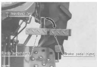
ATTENTION:
When running on the road, be sure to interlock the right and left pedals as illustrated above. Otherwise it will be very dangerous, with only one brake working.
■ Parking Brake Lever
Interlock: the right and left brake pedals, step on the pedals and pull the parking brake lever. This procedure locks the parking brake latch on the slots of the brake pedal, applying the parking brake. To release the parking brake, step on the brake pedals again.

■ Differential Lock Pedal
Differential lock is applied in cases where, the wheels are likely to slip, only one of the rear wheel slips, or the tractor climbs a slope or runs over the field rows.
Lightly stepping on the differential lock pedal with the heel makes the rear wheels run at equal speed. To unlock, just release the pedal.

PRECAUTIONS DE SECURITE:
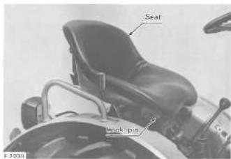
The seat can be adjusted to three preset positions to the operator's convenience. The adjustment is affected by lifting the front of the seat and resetting the lock pin from one to another hole.
八
□
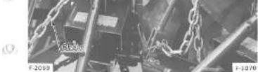
■ Implement Lock Chain (B5100D/B5100E: Option)
When transporting on the road or checking the implement in the raised position, be sure to hook one end of the implement lock chain on the chain bracket as shown in the picture so as to prevent the implement from dropping. When the chain is not being used, remove it from the bracket, and fasten it to the hook.
八
■ Siège
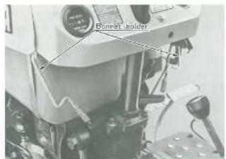
How to Open the Bonnet
open the bonnet, take off the bonnet holder on the right left sides. At this point, check the levels of fuel, cooling or and battery electrolyta.

natural_image
Open industrial machine with visible internal components and wiring (no text or symbols)FETY PRECAUTION:
er open the bonnet while the engine is running. It is very rigorous because the drive belts, dynamo and cooling for running at high speeds.
natural_image
Close-up of an open industrial machine with visible internal components and wiring (no text or symbols)PRECAUTIONS DE SECURITE:
■ Hydraulic Circuit Changeover Unit
(B5100D/B6100D/B6100E/B7100D)
When a hydraulically operated implement is connected to the tractor, oil flow can be switched to the control valve on the implement by means of the grip on the sub-control valve assembly.


- With the arrow on the grip in the position shown in the figure, all flows into the cylinder in the tractor.


[1] Remove the plug from the sub-control valve assembly and connect the hsa from the implement to the assembly (screw: PS%).
(2) Remove the plug from the case front cover, and connect the return hose from the increment to the cover (screw: PFN).
(3) Throw the control lever on the tractor backwards, and turn the grip on the sub-control valve assembly by 180°. Oil will then flow into the control valve on the implement.


NOTE:
- If an implement (e.g., rotary tiller) or a balance weight is connected to the rear of the tractor, lower the implement or weight a little so that the control lever can be operated with ease.
(B5100D/B6100D/B6100E/B7100D)
3.3 WATER OUTLET AND HEAT INDICATOR HOLE (B6100D/B6100E/B7100D)
How to Use Hot Water (B6100D/B6100E/B7100D)
n order to use this model's cabin heater, take the hot water from the outlet (thread size PS 3/8), and return it to the inlet thread size PS 3/8).
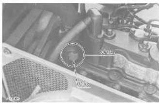

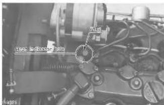
Heat Indicator Hole (B6100D/B6100E/B7100D)
n order to install the heat indicator on the cylinder head, use he hole (thread size M16 x 1.5).
3.3 SORTIE D'EAU ET TROU POUR
THERMOMETRE (B6100D/B6100E/B7100D)

4. Operating Instructions Instructions d'utilisation
4.1 PRE-START CHECKS
Prior to starting the engine, make pre-start checks according to the Service Schedule on page 21.
4.2 STARTING AND STOPPING
■ Starting
(1) Sit down on the operator's seat.
(2) Step on the parking brake
(3) Set the main gear shift lever and the PTO speed change lever to the neutral position.
(4) Throw the accelerator lever to the high position.
(5) Plug the key into the key switch and turn is on.
(6) Make sure that the engine oil pilot lamp has lit up.
(7) Fully step on the clutch pedal and turn the key switch left, waiting for the glow lamp to turn red.
For the necessary preheating time, refer to the table below:
| Temperature | Preheating time | |
| 86100D | above 0°C | about 15 sec. |
| 86100C | ||
| 87100D | below 0°C | about 30 sec. |
| 86100D | above 0°C | about 25 sec. |
| 86100E | below 0°C | about 40 sec. |
(8) Turn the key switch to the start position and the starter will run and the engine will then start.
(9) Make sure that the engine oil pilot lamp has gone off. If the lamp is still on, immediately stop the engine and check the lubrication system (See page 28 to 29)
(10) Perform warm-up operations by running the engine at the medium speed.
©
①
CAUTION:
(1) While the engine is running, do not turn the key switch.
(2) If the engine does not catch motion 10 seconds after the key switch is turned on, wait about 20 seconds more and repeat the procedure above. If the key switch is continuously set to the Start position for more than 30 seconds, it may lead to the trouble with the starter.
(3) Be sure to perform warm-up operations regardless of the ambient temperature. If the tractor is run before the engine warms up, the engine life is reduced, and the tractor life, in turn, will also be affected.
4.1 VERIFICATIONS AVANT LE DEPART
Do not attempt to start the engine in a closed room. Otherwise this will contaminate the air with exhaust, leading to the risk of poisoning.
Make it a habit to start the engine after throwing the main gear shift; lever and PTO speed change lever to the neutral positions then disengaging the clutch. If this procedure is not observed, the tractor may dangerously lunge forward the moment the engine starts.
Starting with Dull Battery or in Cold Weather
form the following procedure between the steps (6) and (9)
Starting:
Pull out the decomp knob
I Depress the clutch pedal all the way and turn the key switch to the start position.
After the flywheel starts to run at full pitch in 3 to 5 seconds, push the decomp knob back. If necessary, operate preheating before drawing the decomp knob.
AUTION:
then the ambient temperature is less than minus 15°C, nove the battery from the tractor and store it somewhere arm until next operation.
Stopping
Slow down the engine to less than 16.7 r/s (1000 rpm) by throwing the accelerator lever backward and releasing the accelerator pedal.
- Fully raise the stop lever and the engine will stop.
- Turn the key switch off and draw the key out.
(UTION:
though engine can be stopped by drawing the decomp knob, s should never be done except in such an emergency case it the engine cannot be stopped by pulling the engine stop or. Especially, if the decomp knob is drawn while the gine is running at high speed, there is the danger that the ve seat may bite dust or that the decompression device y develop troubles. For this reason, be absolutely sure not draw the decomp knob when the engine is running except emergency cases.
3 DRIVING
Starting
Depress the clutch pedal and disengage the clutch.
Shift the main and high-low gear shift levers to the desired speed positions.
Unlock the parking brake.
Speed up the engine by throwing the accelerator lever forward or by stopping on the accelerator pecal.
Slowly release the clutch pedal and the tractor will start to move.
PRECAUTIONS DE SECURITE:
(1) Do not start the tractor with the parking brake on. Trouble may occur.
(2) Do not drive with your foot on the clutch pedal.
SAFETY PRECAUTIONS
(1) Sudden release of the clutch pedal makes the tractor, dangerously lunge forward.
(2) Gear shift cannot be accomplished during driving. To do this, be sure to stop the tractor by fully stepping on the clutch pedal.
(3) Interlock the right and left brake pedals before starting. Uneven braking results in a sharp turn, which may even turn over the tractor.
(4) Do not allow any person other than the driver to ride on the tractor.
(5) Do not drive the tractor close to the edges of ditches or banks which may break under the weight of the tractor, especially when the ground is loose or wet.
(6) When turning the tractor, be sure to slow down the engine and, as necessary, throw the high-flow gear shift lever to LOW.
(7) Do not drive the tractor on the road with the implement in motion.
(8) After the differential lock has been used, be sure to see that it has been released.
[9] When going down a slope, apply the engine brake. Stepping only on the brake pedal is dangerous.
■ Stopping
(1) Slow down the engine
[2] Step on both the clutch pedal and brake pedal and the tractors will stop.
(3) Throw the main gear shift lever to the neutral position and release the clutch pedal.
(4) Inte-lock the right and left brake pedals then apply the parking brake.
SAFETY PRECAUTIONS:
(1) When parking, be sure to apply the parking bake.
(2) When parking on a stop, be sure to take the added precaution against rolling by placing stones or something behind the wheels.
[Non-Text]

ATTENTION:
(3) Before getting off the tractor, be sure to stop the engine and lower the implement to the ground to prevent sudden dashing or implement drop.
4.4 CHECK DURING DRIVING
While driving, make the following checks to see that all the parts are functioning normally.
Cooling Water
If the temperature of the cooling water rises above 100^ C and the vapor and water don't stop running out of the overflow pipe, immediately stop the engine and exercise the following checks and remedies, bearing in mind the safety precautions.
(1) Shortage or leakage of the cooling water.
(2) Foreign matter on the radiator net and dust; and dirt between the radiator fins and tube.
(3) Slackness of the fan drive bolt.
(4) For formation in the radiator tube.
(5) Unnecessary addition of anti-freeze to the cooling water not in cold weather.
SAFETY PRECAUTION:
To remove the radiator cap, wait for about 10 minutes after stopping the engine. Immediate removal of the radiator cap lets the hot water spray out, scalding the operator.
■ Engine Oil Pilot Lamp
The pilot lamp signals to the operator that the engine oil pressure falls under the prescribed level. If the lamp should go on during driving and off even at more than 18.7 v/s (1000 rpm), immediately stop the engine and check:
(1) The level of the engine oil (See page 28).
(2) The conditions of the lubrication system (See page 29)
■ Fuel
Be careful for the fuel tank not to run dry. Otherwise air may be sucked into the fuel system. Should this happen, the system must be oled. (See page 24 to 25).
Exhaust Fumes
(1) Exhaust fumes are colorless at normal output drive.
(2) Exhaust turns become a little colored when output power develops above the rating, but does not affect the traction. If the exhaust turns dark continuously during driving, this probably indicates an overburden on the engine. In such a case, corrective action should be applied to conditions of operation so that subsequent damage to the engine can be avoided.
Should the following abnormally take place, immediately stop the engine.
(1) The engine suddenly slows down or speeds up. (2) Unusual noises are suddenly heard.
(3) Exhaust fumes suddenly become very dark.
(4) The engine oil pilot lamp goes on during driving.
For checks and remedies in the above situations, consult your dealer for instruction.
4.5 DIRECTIONS FOR OPERATING DIFFERENTIAL LOCK PEDAL
The proper use of the differential lock enhances your tractor performance to a great extent while its wrong use may subject the operator to serious dangers or lead to tractor troubles. Thus be sure to observe the following precautions when applying the differential lock.
(1) Do not apply the differential lock immediately and instead limit its use to the below situations. Note, however, that the differential lock may sometimes be not engaged when the right and left rear wheels are running at the same speed.
- When the tractor enters or leaves the farm field, it cannot run straight because of excessive individual wheel-spin under difficult or siloery field conditions.
- One rear wheel is caught in a loose area of the field and the tractor cannot run due to wheel-spin.
- In the case of plowing, the rear wheel closer to the ridge is caught in the loose soil and is affected by wheel-spin.
(2) The use of the differential lock must be limited to a particular period of time and cannot be applied beyond that limit.
(3) When the rear wheel is subjected to excessive loads, even recessing the pedal sometimes may not unlock the differential although the pedal springs back. Should the differential not unlock when during the tractor, lightly posted on the brake pedal opposite to the turn side or else turn back, the steering wheel and run the tractor straight. By doing so, the differential can be unlocked. If the brake pedal of the turn side is depressed during turning, the differential lock system takes on an undue load. Be careful about such a improper operation.
The tractor cannot turn with the differential locked and attempting this is very dangerous. Take utmost care not to do this.
■ Arrêt Urgent
event trouble from occurring, it is important to know editions of the tractor well. Check it before starting.
TV PRECAUTION:
are to check and service the tractor in a flat ample block the engine shut off and the parking brake on.
neck the parts where there was trouble the day before
1) Check the tire pressure, and check for wear and
damage (See page 38) 2) Check for oil and water leaks. (See page 26 to 39) 3) Check the engine oil level and check for contamination (See page 28).
4) Check the amount of transmission oil and whether it is contaminated. (See page 30)
(6) Check if there is enough cooling water in the radiator (See page 35)
(7) Check for dust load on the air cleaner dust cup. (See page 38 to 39)
(8) Check the tractor body for damage and check that all bolts and nuts are tight.
(9) Check the pilot lamps for failure. (10) Check the license plate for stains and damage. (11) Check for enough chassis grasing or calling king pin, rod end, pedal shafts, center pin, front axle casing spheres, interlock rods, front wheel drive level. (See page 32 to 34)
) While sitting in the driver's seat,
(12) Check the brake and clutch sides. See page 43 to 44
(13) Check the steering wheel. (See page 44)
II. Turning the key switch on;
(15) Check the performance of the profit margin and
(16) Check the electric horn
5) Starting the engine, (17) Check the color of the exhaust fumes.
5.1 VERIFICATIONS JOURNALIERE
During the breaking-in period, observe the following:
(1) Change the engine oil and clean the oil filter after first 35 hours of use. (See page 28 to 29)
(2) Change transmission oil after first 50 hours of use (in transmission case, front axle case, front wheel gear case.)
13) Avoid reduction of the
131 Avoid sudden starting and braking
(4) Warm up the engine sufficiently in cold weather,
(5) Do not drive the tractor at excessively high speeds.
(6) Slow down on bumpy roads and slopes.

5.3 PERIODIC CHECKS
| Check Intervals | Check Points | Reference Pages |
| Every 50 service hours | Clean hydraulic oil filter. | 31 |
| Every 75 service hours | Change engine oil. | 28 to 29 |
| Every 100 service hours | Clean air cleaner element. | 36 to 39 |
| Clean fuel filter | 27 | |
| Check nozzle piece and change it when horsepower drops abnor- mally. | ||
| Check fuel pipe | 25 | |
| Check belt tension. | 41 to 42 | |
| Check clutch play. | 42 to 43 | |
| Check brake play. | 43 to 44 | |
| Check steering wheel play. | 44 | |
| Every 150 service hours | Charge engine oil filter cartridge. | 29 |
| Check radiator hose. | 37 | |
| Every 300 service hours | Change transmission oil in: Transmission case, front axle case, front wheel gear case (light and left), steering case | 30 to 32 |
| Every 500 service hours | Clean radiator interior. | 37 |
| Every one to two service months | Top up battery. | 39 to 40 |
| Every 3 service months | Change inhibitor and cooling water. | 35 to 38 |
| Every service year or every 6 times of cleaning | Change air cleaner element. | 38 to 39 |
| Every 2 service years | Change battery. | 39 to 40 |
| Change radiator hose and lightener band. | 37 | |
| Change fuel pipe and lightener band. | 26 |
5.2 RODAGE (LES 60 PREMIERES HEURES D'UTILISATION)
■ Checking and Refueling
[1] Check the fuel level.
Take care that the fuel level does not fall under the prescribed lower limit.
| B6100D/B6100E/B7100D | 13 (10 : steel tank type) |
| B5100D/B5100E | 8 (7.8 : steel tank type) |
(2) Use high-speed diesel fuel or No. 2 diesel fuel.
(3) Use No. 1 diesel fuel, if temperature is below -10°C.

SAFETY PRECAUTION:
Stop the engine before adding fuel. Keep away from sparks and flames.
CAUTION:
(1) Always use a strainer in refueling, or the mingled dust and sand may impair the fuel injection pump.
(2) Once the fuel tank becomes empty air is admitted to the fuel system, in such case, starting cannot be effected without bleeding.
■ Bleeding the fuel line
Air must be removed
(1) when the fuel filter and piping are removed.
(2) when fuel is used up, or
(3) after the tractor has not been used for a long period of time.
6.1 CARBURANT
Bleeding procedure is as follows:
(1) Fill the fuel tank with fuel, and open the fuel cock.
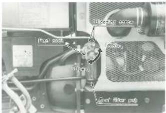
(2) Twist off the air went plug at the top of the filter with two turns.
(3) When bubbles disappear from fuel coming out of the plug, twist it back on.
natural_image
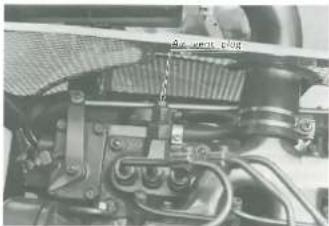
Close-up of an internal engine bay with visible hoses and components (no text or symbols)(4) Open the air vent plug on the fuel injection pump.
(5) Pull the engine stop lever to stop the engine, and start the cell starter for about 10 seconds.
CAUTION:
Always pull out the engine stop lever before starting the cell starter.
[6] Close the air vent plug when air bubbles disappear from the fuel flowing out.
natural_image
Close-up mechanical assembly showing internal components and no visible text or symbolsAlthough checking the fuel pipe connections is recommended every 100 service hours, it should be done every 6 months if operation does not exceed 100 hours in 6 months. (1) If the tighter band is loose, apply a slight coat of lubricant onto the threads and securely retighten it.
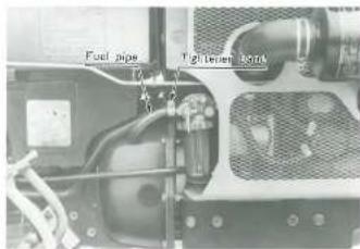
(2) The fuel pipe is made of rubber and ages regardless of period of service. Change the fuel pipe together with the tighterer band every two years and securely tighten.
(3) If the fuel pipe and tighter band are found damaged or degraded earlier than two years, then change or remedy.
(4) After the fuel pipes and tightener band have been changed, bleed the fuel system.
SAFETY PRECAUTIONS:
(1) Stop the engine when attempting the check and change prescribed above.
(2) Do not fail to check the fuel pipe periodically because the impairment of the fuel pipe may lead to dangerous firing.
CAUTION:
When the fuel pipe is disconnected for change, close both ends of the fuel pipe with a piece of clean cloth or paper to prevent dust and dirt from entering. Entrance of dust and dirt causes malfunction of the fuel injection pump. In addition, particular care must be taken not to admit dust and dirt into the fuel pump.
Cleaning the Fuel Filter Pot
then period of operation reaches approx. 100 hours, clean the level filter as follows:
) Close the fuel filter pot cock.

3) Urscrew and remove the top cup, and rinse the inside with light oil.
1) Take out the element and dip it in the light oil to rinse.

After cleaning, reassemble the fuel filter, keeping out dust and dirt.
To bleed the fuel filter, open the fuel cock and loosen the air vent screws (two) with two or three turns of a wrench. When air bubbles disappear from the fuel flowing out, retighten the air vent screws. Also bleed the injection on pump.
(UTION)
dust and dirt enter the fuel, the fuel pump and injection zile are subject to quick wear. To shut off this, be sure to an the fuel filter pot periodically.
■ Oil Level Check and Replenishment
(1) Check engine oil either before starting the engine or 5 minutes or more after the engine has stopped.
(2) To check the oil level, draw out the oil level gauge, wipe it clean, replace it, and draw it out again. Check to see that the oil level lies between the two notches.
[3] If the level is too low, add new oil to the prescribed level at the oil port.
Use Enging Oil SAF or equivalent.
Capacity
| 36100D/86100E/B7100D | 34 |
| 3510CD/B5100E | 23 |
B6100D/B6100E/B7100D

B5100D/B5100E


) When using an oil of different type, make or viscosity from the previous one, remove all of the old oil. Never mix two different types of oil.
- Use the proper Engine Oil SAE according to the ambient temperatures.
| Below 0°C | SAE10W or 10W-30 |
| 0-25°C | SAE20 or 10W-30 |
| Above 25°C | SAE30 or 10W-30 |
Engine Oil Change
) To charge the used oil, remove the drain plug at the bottom of the engine and drain the oil completely. All the used oil can be drained out easily when the engine is still warm.

1) Top up with the new oil up to the upper notch on the oil gauge.
AFETY PRECAUTION:
before changing the oil, be sure to stop the engine.
Oil Filter Cartridge Change
1) The oil filter cartridge must be changed every 150 service hours.
1) Apply a slight coat of oil onto the cartridge packing.
To install the new cartridge, screw it in by hand until the packing contacts the seat, and then securely tighten by hand.
After the new cartridge has been replaced, the engine oil normally decreases a little. Thus see that the engine oil does not leak through the seal and be sure to read the oil level on the gauge. Then, replenish the engine oil up to the prescribed level.

AFETY PRECAUTION:
e sure to stop the engine before changing the oil filter caridge.
natural_image
Close-up of a mechanical component with no visible text or symbolsPRECAUTION DE SECURITE:
■ Transmission Oil Check and Replenishment
Draw out the oil gauge atop the transmission case and wipe off oil. Then, replace it and remove it again to determine the oil level. The appropriate oil level is on the upper notch. If short, replenish through the oil port.
KUBOTA UDT oil is now used for the transmission of this tractor. Whenever replenish or replace, use only multi-purpose oil shown the below or equivalents.
| Maker | Brand |
| KUBOTA | UDT hydrostatic transmission oil |
| SHELL | DONAX-TD, DONAX-TM |
| Mobil | Mobil Fluid 350 |
| Exxon | Torque Fluid 56 |
Do not mix up the other nature of oil other than above. When it is necessary to use SAE No. 90 gear oil by some reasons, you must drain oil off completely.
Capacity
| B6100D/B6100E/B7100D | 11.5 |
| B5100D/B5100E | 8.5 |
Mobil. flod 425
B6100D/B6100E/B7100D B5100D/B5100E

■ Transmission Oil Change
The oil in the transmission case is also used for the hydraulic drive system.
To drain the transmission case, place a oil pan underneath the transmission case and remove the drain plugs at the bottom of the transmission case.
After draining, disassemble and clean the hydraulic oil filter. Then, after reassembling fill with new oil.
6.3 HUILE DE TRANSMISSION
| Marques | Type |
| KUBOTA | UDT hydrostatique transmission oil |
| SHELL | DONAX TD, DONAX TM |
| Mobil | Mobil Fluid 350 |
| Exxon | Torque Fluid 56 |
| Motul | TPH 97 |
| BP | Tractan 10 |
■ Cleaning Hydraulic Oil Filter (in changing transmission oil)
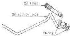
As the finest dust in the oil could impair the component parts of the hydraulic system precision-built to withstand high pressure, the suction pipe end is fitted with an oil filter. When changing the transmission oil, disassemble and rinse the oil filter with light oil to completely clean off dust. On reassembly, undertake utmost care not to damage the parts.
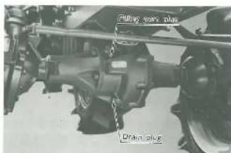
5.4 CHANGING FRONT AXLE CASE OIL (B5100D/B6100D/B7100D)
Remove the drain and filling port plugs. After draining, replace the drain plug and fill with new oil.
Type of oil: Gear Oil SAE 80 or equivalent Quantity of oil.
| B5100D/B6100D | 0.5 |
| B7100D | 0.7 |
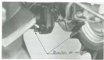
Remove the drain and filling port plugs to discharge the used oil. After draining, replace the drain plug and fill with new oil. Type of oil: Gear Oil SAE 80 or equivalent Quantity of oil
B51000/B61000/B71000 0.15
6.5 REMPLACEMENT DE L'HUILE DES CAR-TERS DE ROUES (DROITE ET GAUCHE) (B5100D/B6100D/B7100D)
O
6.6 OILING AND GREASING POINTS BEFORE STARTING
Oil or grease the following points before starting.
■ King Pins, Rod Ends and Center Pin
Gross the king pins, rod ends and center pin with the provided grease gun.
B5100D/B6100D/B7100D


6.6 POINTS DE HUILAGE ET DE GRAISSAGE AVANT LE DEMARRAGE
B5100D/B6100D/B7100D

\$100E/B6100E
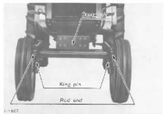
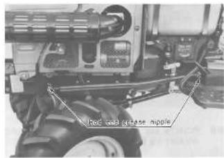
Interlock Rod
I or grease the interlock rod and sliding holder

B5100E/B6100E
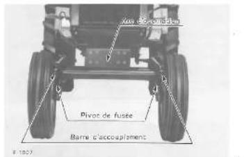
■ Pedal shafts
Grease the greaser nipples on both ends of the pedal shaft.

O
0

0
■ Front Wheel Drive Lever (B5100D/B6100D/B7100D)
Oil the ball race at the root of the front wheel drive lever
①

ough the radiator is of rugged construction, wrong hanging badly affects the performance of the engine. A full tank cooling water is enough for one day's work. Make it a rule check the level of the cooling water prior to operation.
Checking, Replenishing and Changing Cooling Water
Remove the radiator pressure cap and check to see that the water level is just below the port. If short, add fresh tap or well water.
| B6100D/B6100E/B7100C | 4.6Ω |
| B5100D/B5100F | 3Ω |

CAUTION:
(1) Never replenish with muddy water or salt water. (2) Securely tighten the pressure cap.
When draining the used cooling water, open the water drain cock and the pressure cap at the same time. With the pressure cap closed, complete drainage cannot be achieved.

6.7 RADIATEUR
(3) Be sure to close the pressure cap securely. If the cap is loose or improperly closed, water may spill out and water shortage will result.
(4) Additives to cooling water
Hot season: Kubota Fur Inhibitor No. 11
Cold season: Anti-freeze solution (at under 0°C)
SAFETY PRECAUTIONS:
(1) When changing the cooling water, be sure to stop the engine.
(2) Do not open the pressure cap while the engine is running under heavy loads or immediately after the engine has stopped. Otherwise, hot water may spray out, scalding the operator. So make it a habit to wait for about 10 minutes before opening the cap.
■ Checking and Cleaning Radiator for Flooding
(1) Adherence of insects and chaff to the radiator net decreases cooling performance. In such cases, detach the net and wash away the obstacles.

natural_image
Close-up of a Kudo agricultural machine with visible exhaust pipe and brand number 87100 (no readable text beyond branding)(2) Remove the dust from between the fins and the tube.
(3) Tighten the fan drive belt as necessary. For this, refer to page 39.
(4) If fur forms in the tube, clean with the Kubeta Fur Inhibitor.
ng radiator hose tightness is prescribed about every 150 hours, but every 6 months is all right so long as service in does not exceed 150 hours in 6 months.
the tighter band is loose, securely retighten and plv a slight coat of oil.
ie radiator hose is made from rubber and tends to ago. must be changed every two years. Together change e tightener band and securely tighten.
| Paris Name Noms des pôces | B61000/B6100C/B7100D | B5100C/B5100E | ||
| Code Nos.Nos de Code | UnitUnité | Code Nos.Nos de Code | UnitUnité | |
| Radiator nose 1 Fixation de radiateur 1 | 15554-7285-1 | 1 | 15261-7285-1 | 1 |
| Radiator nose 4 Fixation de radiateur 4 | 15554-7284-1 | 1 | 15261-7294-1 | 1 |
| Tightener band Bande de Fixation | 15261-7278-2 | 4 | 15261-7278-2 | 3 |
| 15108-7287-3 | 1 | |||
sota Fur Inhibitor No. 11
in Kubota Fur Inhibitor No. 11 prevents fur formation the cooling water. Fur, which builds up in either and or soft water, sharply reduces cooling efficiency.
So Fur Inhibitor is effective for 3 months so a complete range of cooling water must be done every 3 months.
nedying Water Leakage
ator leakage can easily be eliminated with the Kubota aviator Cement No. 40.
water leakage should become extremely excessive, insult: your local dealer.
aning Cooling System
the water cooling system should be cleaned on the following occasions:
Every 500 service hours
When add on an anti-freeze solution.
When changing from water containing anti-freeze to pure water
then cleaning the water cooling system, the Kubota or Inhibitor No. 20 is recommended to effectively wash way the built-up fur.
ti-Freeze
cooling water freezes, the engine cylinder and radiator rank. In cold weather when the temperature drops below drain out the water or add a proper amount of anti-freeze the tractor is shut down.
here are two types of anti-freeze solutions, permanent type (IPT) and semi-permanent type (ISPT). For the subota Engine, be sure to use the permanent type.
When anti-freeze is used for the first time, fill and drain lean water two or three times so as to completely clean be inside of the radiator.
(3) Preparations of anti-freeze solutions vary with temperatures under which the engine is operated and do also with suppliers. For this reason, prior to use, ask the store for the instructions as to the proper amount and method of use. Remember that the effective cooling water capacity of the radiator is shown on the table below.
| B5100D/B610CE/B7100D | 4.5 |
| B5100D/B510CE | 3 |
(4) Stir the anti-freeze well in the water and then pour the mixture into the radiator.
(5) When the cooling water mixed with anti-freeze decreases due to evaporation, replenish with water only. If loss has been due to leaking, water and anti-freeze mixture with the same mix ratio as the original preparation.
(6) Anti-freeze solutions absorb moisture, so be sure to securely close the container after use.
(7) Do not use an anti-freeze and a fur inhibitor at the same time. This may cause sludge to form, adversely affecting the engine parts.
6.8 TIRE PRESSURE
Though the tire pressure is factory-set to the prescribed level, it naturally drops slowly in the course of time. Thus, check it everyday and inflate as necessary. To inflate the wheel tires, use an air compressor or hand pump.
| Normal wheel tire pressure | ||
| Front | Rear | |
| B510CD B610CD B710CD | 0.1 MPa (1.0 kg/cm2) | 0.12 MPa (1.2 kg/cm2) |
| B510DF B610DF | 0.16 MPa (1.5 kg/cm2) | 0.12 MPa (1.2 kg/cm2) |
| B510CE T B810CE T | 0.18 MPa (1.3 kg/cm2) | 0.08 MPa (0.8 kg/cm2) |

6.9 AIR CLEANER
[1] As the air cleaner uses a dry element, never apply oil.
(2) Do not let dust build up to more than a half of the dust cup. Detach the dust cup and throw away the dust—normally once a week, but everyday if working conditions are especially dusty.
3) Do not touch the filter element except in cases where cleaning is required.
4) When cleaning the element, refer to the Instructions attached.
5) If the element is strained with carbon or oil, apply one of the following cleansers:
• TR-10000 (by Tokyo Filter Co.)
• ND-1500 (by Japan Donaldson)
6) Change the element once yearly or every time the air cleaner is rinsed with water (6 times a year).
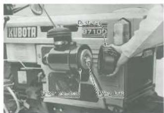
CAUTION:
Is sure to refit the dust cup with the arrow (on the rear) upright. If the dust cup is improperly refitted, dust passes by the dust cup and directly adheres to the element, badly affecting the service life.
i.10 BATTERY
fishing the battery shortens the service life and adds to maintenance costs. Be sure to handle it correctly so that it will develop its full potential performance.

natural_image
Interior view of a mechanical or electronic device with visible components and wiring (no readable text or symbols)ATTENTION:
natural_image
Close-up of a mechanical assembly with visible components and no readable text or symbols(1) If the battery is dull, the engine is difficult to start and the lamps become dim. It is important to check the battery daily and recharge before such trouble occurs.
(2) The water in the electrolyte evaporates during recharging. Liquid shortage damages the battery and excessive liquid spills over and damages the tractor body. If short, be sure to top up the battery with distilled water.
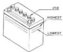


(3) To top up the battery connect the battery positive terminal to the charger positive terminal and the negative to the negative, then recharge in the standard fashion.
(4) A boost charge is only for emergencies. It charges partially the battery at a high rate and in a short time. When using a boost-charged battery, it is necessary to recharge the battery as early as possible after the operation has been finished. Failure to do this extremely affects the service life due to over discharge.
CAUTION:
(1) When connecting the battery, do not reverse the polarities. Connection with reverse polarities causes troubles to the battery and electrical system in the tractor.
(2) When disconnecting the cord from the battery, start with the negative terminal first. When connecting, start with the positive terminal first. Reversing the steps may cause short-circuiting, should a screwdriver touch the terminals.


SAFETY PRECAUTION:
Be careful not to allow the electrolyte to connect your clothes. The strong acid will eat holes in it.
■ Directions for Storage
(1) When shutting down the tractor for long periods of time, remove the battery from the tractor, top up it, adjust the electrolyte to the proper level and store in a dry place out of direct sunlight.
(2) The battery self-discharges even while it is stored. Re-charge it once a month in hot seasons and once every two months in cold seasons.
7. Adjustments Reglage
SAFETY PRECAUTION:
When making adjustments, park the tractor on flat ground and apply the parking brake.
7.1 BELT TENSION
B6100D/B6100E/B7100D
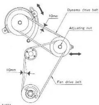
If the fan drive belt or the dynamo drive belt becomes loose, the engine may sometimes overheat, or the battery may not be charged. When the fan drive belt is deflected excessively, loosen the adjusting nut and tighten the tension bolt to stretch the belt. After the adjustment, be sure to tighten the adjusting nut. When the dynamo drive belt is loose, loosen the bolts and turn the dynamo to stretch the belt. Finally, tighten as the three bolts.
Moderate belt tension
The belt should deflect approx. 10mm when the center of the belt is depressed with a finger pressure of 10 kg.
PRECAUTION DE SECURITE:
If the fan drive belt becomes loose, the engine may sometimes overheat. When the belt is deflected excessively, loosen the adjusting nut and tighten the tension bolt to stretch the belt. After adjustment, securely tighten the adjusting nut.
Moderate belt tension:
The belt should deflect approx, 10mm when the center of the belt is depressed with a finger pressure of 10 kg.
6
G

7.2 CLUTCH
Moderate clutch pedal play ranges from 2 to 4 mm and moderate clutch pedal travel is 8 mm.
7
⑦


B5100D/B5100E
F2040
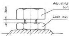
(1) If the clutch becomes difficult to disengage or pedal play decreases, adjust the length of the intermediate rod after removing the pin. When the clutch is difficult to disengage, extend the intermediate rod. When the clutch play is too little, shorten the intermediate rod.
(2) To adjust pedal travel, loosen the lock nut and turn the adjusting bolt to the point where the clutch is disengaged completely.
7.3 BRAKE
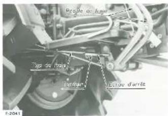
If brake pedal travel becomes too great or travel varies too greatly between the right and left pedals, loosen the turn-buckle lock out and turn the turnbuckle in the desired direction until the proper pedal travel is achieved. Moderate right and left pedal play ranges from 2 to 10 mm.
After adjustment, interlock the right and left brake pedals and finally tighten the lock nut securely.
B8100D/B6100E/B7100D

Moderate steering wheel play is zero to 30mm. To adjust this, loosen the lock nut and turn the adjusting bolt to the right. After adjustment, securely retichten the nut.
natural_image
Close-up mechanical assembly showing hoses and components (no visible text or symbols)0


7.5 IMPLEMENT LOWERING SPEED
Implement lowering speed can be adjusted in accordance with the type of the implement and operating conditions. To do this, after loosening the lock nut, tighten or loosen the adjusting bolt on the hydraulic control valve. Tightening the adjusting bolt slows down the lowering speed while lousing it accelerates the speed. After adjustment, securely tighten the lock nut.
Note that the proper lowering speed of a rotary tiller is such that it takes two or three seconds to descend from the top position to the ground.
![V6.00000 502 [18]](/content/2026/05/1004758/images/fb7f5a797902de396b0f3d1aa01b66f59219d58ce4c37b10aaa170420f7a930d.jpg)
7.6 IMPLEMENT LIFTING AND LOWERING LIMITS
The implement lifting and lowering limits can be changed by shifting the locker (A) or (B).

7.5 VITESSE DE DESCENTE DE L'OUTIL
The lower limit can be changed by shifting the fixing position of the locker (A). Shifting the locker (A) backward lowers the limit and shifting it forward raises the limit.
■ Upper Limit
The upper limit can be changed by shifting the fixing position of the locker (B). Shifting the locker (B) backward lowers the upper limit and shifting it forward raises the limit.
7.7 REAR WHEEL TREAD
The rear wheel is fixed to the hexagonal axle and hub by the use of a pin and set bolt. Rear wheel tread can be changed at 3 steps (B6100D/B6100E/B7100D). 2 steps (B5100D/B5100E) by selecting one of the pin holes on the exit. Adjust the rear wheel tread according to operating conditions. Tread (Between the center of the tins)
| B6100D/B6100E/B7100D | 650mm, 710mm, 760mm |
| B5100D/B5100E | 840mm, 740mm |


7.8 TOE-IN
The toe-in needs to be adjusted if the tractor runs unstably or if the steering wheel becomes heavy or difficult to handle. Measure the front wheel distances (AB and CD) and adjust to the following value:
CD minus AB should be approximately zero to 5mm, which is common to the B5100D/B5100E/B5100D/B5100E/B7100D. To perform this adjustment, losten the tierod lock nut and turn the tierod the desired number of turns.
■ Limits Inférieure
7.8 PARALLELISME
natural_image
Front view of a small wheeled vehicle with large tires and mounting feet (no visible text or symbols)7.9 CENTER PIN
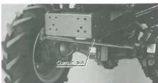
If cross-axle play occurs between the front wheel support and the front axle, it must be eliminated in the following fashion.
First remove the set spring, then reighten the slotted nut on the front axle while turning the steering wheel until the play is eliminated. Lastly replace the set spring.
7.10 EXHAUST PIPE WITH MUFFLER
The exhaust pipe can be rotated. Adjust this properly while the tractor operate between the crop rows.


natural_image
Front view of a heavy-duty off-road vehicle with visible tracks and suspension components (no text or symbols)7.9 AXE DE L'ESSIEU
| Trouble | Cause | Countermeasure | Preventive measure |
| The cell starter does not start. | *Lights have been overused until they become dim. | *Charge the battery for a long enough time by the standard method. | *Charge the battery properly, of avoid overdis-charging. |
| *Battery has not been recharged. | |||
| *Poor terminal connection. | *Clean the terminal and tighten securely. | *Keep the terminal clean and tight. Apply grease and treat with anti-corrosives. | |
| *Battery is dead. | *Renew battery. | ||
| The cell starter does not start ever after charging, and lights soon become dim. | *insufficient charging. | *Charge the battery for a long enough time by the usual method. | *Top up the battery before use. |
| When viewed from top, the top of plates looks whilst. | *Battery was used with an insufficient amount of electrolyte. | *Add distilled water and charge the battery. | *Regularly check the electrolyte level. |
| *Battery was used too much without recharging (overd discharged). | *Charge the battery for a long enough time by the usual method. | *Charge the battery properly, or avoid overdis-charging. | |
| Recharging is impossible. | *Battery is dead. | *Renew battery. | |
| Terminas are severely corroded and heat up. | *Poor terminal connection or stained terminal | *Clean the terminal and tighten securely. | *Keep the terminal clean and tight. Apply grease and treat with anti-corrosives. |
| Battery electrolyte level drops rapidly. | *There is a crack or pin holes in the electrolytic cells. | *Renew electrolytic cells. | *Install the electrolytic cells securely. |
If you have any questions, contact your Kubota dealer.
8.2 ENGINE TROUBLESHOOTING
If something is wrong with the engine, refer to the table below for the cause and its corrective measure.
| Trouble | Cause | Countormoasure |
| Engine is difficult to start. | 1) No fuel flows. | 1) Check the fuel tank and the fuel filter, and remove dirt bulldo.2) All fuel passes through the fuel filter and much dust is caught in it.Should there be deposits on the filter, replace it. |
| 2) Air and water is in the fuel system. | 1) Check to see if the fuel pipe coupler bolt and nut are tight.2) Blood the fuel system (See page 24 to 25) | |
| 3) In winter, oil viscosity increases, and engine revolution is heavy. | 1) Pour hot water over the radiator.2) Use oils of different viscosities, depending on ambient temperatures.3 | |
| 4) Battery becomes dull and the engine does not overcome compression | 1) Charge the battery.2) Use the decomp knob.3) In cold weather, always remove the battery from the engine, charge it and store it indoors. Install it in the engine only when the tractor is going to be used. | |
| Insufficient engine power | 1) Insufficient fuel.2) The air cleaner is clogged. | Check the fuel system:Clean the element. |
| Engine stops suddenly | Insufficient fuel. | 1) Refuel.2) Check to see if air mingles in the fuel system. |
| Exhaust fumes are storage color. | Fuel quality is poor. | Change to a quality fuel. |
If you have any questions, contact your Kubota dealer.
-Et
When the tractor is not going to operate for two or three months or longer, clean stains off well and perform the following treatment before storage.
(1) Repair the parts where needed.
(2) Check bolts and nuts for looseness and tighten as necessary.
(3) Apply grease or engine oil to the parts most likely to rust.
(4) Remove the weight.
(5) Pump up the wheel tires to a little above the standard pressure levels.
(6) Change the engine oil end run the engine for five minutes so that the oil circulates through the entire system.
(7) Stop the engine by fully pulling out the engine stop lever.
(8) Drain the radiator.


(9) Lock the clutch pedal with the provided winden block. If the tractor is stored for a long period with the clutch left engaged, the clutch disc may rust, rendering it inoperative.

(10) Lower the implement to the ground.

(11) Remove the battery from the tractor, recharge it, adjust the electrolyte to the proper level, and store in a dry place out of direct sunlight.
(12) The battery runs down over time even while in storage. Recharge it once a month in hot seasons and once every two months in cold seasons.
(13) Store the tractor where dry and sheltered from rain. Further cover the tractor with a sheet.
(14) When leaving the tractor outdoors, keep the muffler out of the rain.
CAUTION:
To clean the tractor stop the engine. If you must clean the tractor with the engine going, utmost care should be taken not to allow water to enter the air cleaner. Engine trouble may occur if water enter the engine.
SAFETY PRECAUTION:
When storing, remove the key from the key switch.
0. Three-point Hitch Attelage trois points
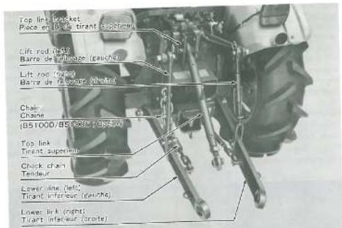
5.2021
1 FITTING 3-POINT HITCH
Using the bolts, install the hitch comp. at the rear of the differential gear case.


10.1. FIXATION DU RELEVAGE TROIS POINTS
(2) Insert the lower link pin into the hitch comp, holes and lock it with the set bolts. (3) To install the top link bracket, remove the chain bracket set bolts, mount the top link bracket on the chain bracket, and bolt them together.

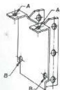
C
- Installation step 1. Temporarily fasten both brackets by placing two bolts (M12) into the holes (A). 2. Install the brackets by placing two bolts (M12) into the holes (B). 3. Securely tighten the bolts on the holes (A).
Fit the check chain brackets and then the right and left lower links onto the lower link pin. Finally attach the link stopper pins to both ends of the lower link pin.
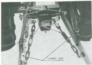
3) Using the pins, fit the right lift rod to the right lower link and to the right lift arm, and fit the left lift rod to the left lower link and to the left lift arm.

6) Fit the top link with the bracket pin.

10.2 3-POINT HITCH ADJUSTMENT
■ Top Link
Implement tilt can be adjusted by changing the length of the top link. Shortening the top link, for example, tilts the implement head down, thereby enhancing plowing efficiency.
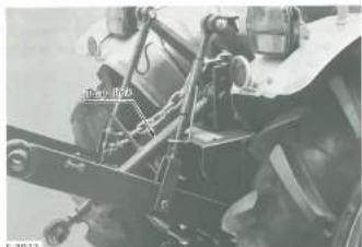
The lift rod (right) is provided with an adjustment handle for extending or shortening the lift rod. To level the implement, operate the handle.

■ Check Chain
The check chain serves to prevent the implement from contacting the 3-point links when the implement is rolling excessively. If the check chain is too taut, it takes on a full load from the implement and is likely to break. Check chain tension should be adjusted to the extent where the lower links do not contact the rear wheel tires.
10.2 REGLAGE DU RELEVAGE TROIS POINTS
■ Tirant Supérieur
An hour meter can be added to the instrument panel. To do this, remove the rubber plug from the hole provided and insert the hour meter. Lastly, lock the instrument with two bolts and connect the cable terminal's to the panel terminals.
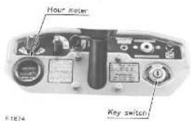
Because the hour reter operates on electricity, it is actuated by setting the key switch at the ⊙ position or at PREHEAT.

The horizontal muffler can be converted into an upright muffler with minor changes of parts.
To convert.
(1) Remove 4 bolts (MB) fastening the elbow and mutifier, then detach the stay.
(2) Turn the muffler inlet upright and lock with 4 nuts (MB)
(3) Replace the horizontal exhaust pipe with an upright exhaust pipe and clamp with the band.

natural_image
Industrial machine labeled 'KOSOTA' with visible components and no readable text or symbols beyond branding


- Wiring Diagram (B5100D/B5100E)

Wiring Diagram (B6100D/B6100E/B7100D)

61
- MANUEL DE L'UTILISATEUR
- TRACTEUR KUBOTA
- Kubota, Ltd. is...
- Kubota Makes all Kinds of Agricultural Machinery for Seeding to Harvesting.
- CAUTION
- PRECAUTIONS
- PREFACE
- FUEL SUPPLY AND ENGINE START
- STARTING
- OPERATION
- LOADING AND UNLOADING
- TRAVELLING
- OPERATING WITH ROTARY TILLER
- OTHER PRECAUTIONS
- OUTSTANDING FEATURES CARACTERISTIQUES EXCEPTIONNELLE
- ■ 4-wheel drive with large-size tires
- ■ Comfortable ride
- ■ Safety design
- ■ Options
- ■ Glow Lamp
- INTERRUPTEURS
- Contact
- ■ Hour Meter (B5100E/B6100E: Option)
- ■ Front Lamp Switch
- ■ Position Lamp Switch (B6100D/B6100E/B7100D)
- ■ Horn Button
- ■ Flasher Lamp
- ■ Decomp Knob
- ■ Engine Oil Pilot Lamp (RED)
- ■ Charge Lamp (B6100D/B6100E/B7100D)
- Electrical Coupler
- ■ Fusibles
- ■ Temperature Gauge (B7100)
- Fuel Gauge
- CONTROLS
- ■ Accelerator Lever and Pedal
- CONTROLES
- ■ Main Gear Shift Lever and High-Low Gear Shift Lever
- AUTIONS:
- Front Wheel Drive Lever (B5100D/B6100D/B7100D)
- (B5100D/B6100D/B7100D)
- CAUTION:
- SAFETY PRECAUTIONS:
- ■ Brake Podals (Right and Left)
- ATTENTION:
- ■ Parking Brake Lever
- ■ Differential Lock Pedal
- PRECAUTIONS DE SECURITE:
- ■ Implement Lock Chain (B5100D/B5100E: Option)
- ■ Siège
- How to Open the Bonnet
- FETY PRECAUTION:
- ■ Hydraulic Circuit Changeover Unit
- (B5100D/B6100D/B6100E/B7100D)
- NOTE:
- WATER OUTLET AND HEAT INDICATOR HOLE (B6100D/B6100E/B7100D)
- Operating Instructions Instructions d'utilisation
- PRE-START CHECKS
- STARTING AND STOPPING
- VERIFICATIONS AVANT LE DEPART
- Starting with Dull Battery or in Cold Weather
- AUTION:
- Stopping
- (UTION:
- DRIVING
- Starting
- SAFETY PRECAUTIONS
- ■ Stopping
- CHECK DURING DRIVING
- Cooling Water
- SAFETY PRECAUTION:
- ■ Engine Oil Pilot Lamp
- ■ Fuel
- Exhaust Fumes
- DIRECTIONS FOR OPERATING DIFFERENTIAL LOCK PEDAL
- ■ Arrêt Urgent
- TV PRECAUTION:
- VERIFICATIONS JOURNALIERE
- RODAGE (LES 60 PREMIERES HEURES D'UTILISATION)
- ■ Checking and Refueling
- ■ Bleeding the fuel line
- CARBURANT
- Bleeding procedure is as follows:
- Cleaning the Fuel Filter Pot
- (UTION)
- ■ Oil Level Check and Replenishment
- Engine Oil Change
- AFETY PRECAUTION:
- Oil Filter Cartridge Change
- PRECAUTION DE SECURITE:
- ■ Transmission Oil Check and Replenishment
- ■ Transmission Oil Change
- HUILE DE TRANSMISSION
- REMPLACEMENT DE L'HUILE DES CAR-TERS DE ROUES (DROITE ET GAUCHE) (B5100D/B6100D/B7100D)
- Checking, Replenishing and Changing Cooling Water
- RADIATEUR
- ■ Checking and Cleaning Radiator for Flooding
- sota Fur Inhibitor No. 11
- nedying Water Leakage
- aning Cooling System
- ti-Freeze
- TIRE PRESSURE
- AIR CLEANER
- i.10 BATTERY
- ■ Directions for Storage
- Adjustments Reglage
- BELT TENSION
- B6100D/B6100E/B7100D
- B5100D/B5100E
- BRAKE
- IMPLEMENT LOWERING SPEED
- IMPLEMENT LIFTING AND LOWERING LIMITS
- VITESSE DE DESCENTE DE L'OUTIL
- ■ Upper Limit
- REAR WHEEL TREAD
- TOE-IN
- ■ Limits Inférieure
- PARALLELISME
- CENTER PIN
- EXHAUST PIPE WITH MUFFLER
- AXE DE L'ESSIEU
- Three-point Hitch Attelage trois points
- FITTING 3-POINT HITCH
- FIXATION DU RELEVAGE TROIS POINTS
- 3-POINT HITCH ADJUSTMENT
- REGLAGE DU RELEVAGE TROIS POINTS
Brand : KUBOTA
Model : B5100D
Category : Uncategorized